1
lJ
1/
L/
another free manual from www.searstractormanuals.com
SE_ARS
MODEL NO.
917.254420
917.254421
Caution:
Read and Follow
All Safety RuBes
And instructions
Before Operating
This Equipment
GT2OHP
TWIN
6 SPEED - 44""
GARDEN TRACTOR
Assembly
Operation
Maintenance
Repair and Adjustment
Repair Parts
Sears,
Roebuck
and
Co.,
Chicago,
IL 60684
UoS.A.
3AFE' "Y
1
2
3
4
5
6
RUL5S
Know the controls
and how to stop quickly_ READ THIS
OPERA TOR'S MANUAL
and instructions
furnished
with
attachments
Do not allow children to operate the machine, Do not allow
adults to operate it without
proper instruction,
Do not carry passengers
Do not mew when children and
others
are around,
Always
wear substantial
footwear_
Do not wearloose
fitting clothing
that could get caught
in moving
parts.
Keep your eyes and mind on your ttactor,
cnower and the
area being cut, Do not let other interests
distract
you
Do not attempt
to operate your tractor or mower
when
not in the drivers seat,
2 3
Use care when pulling loads or using heavy equipment
a Use only approved
drawbar
hitch points.
b Limit loads to those you can safely control.
c, Do not turn sharply.
Use care when backing,
d Use counterweight
or whee! weights when suggested
in the owner's
manual,
24.
2 5
Watch out for traffic
when crossing
or neat roadways.
When using any attachments,
never direct discharge
of
material
toward
bystanders
not allow anyone
near the
vehicle°while
in operation
Handle gasoline
with care - it is highly flammable
a,. Use approved
gasoline
containers,
b. Never remove
the fuel cap of the fuel tank or add
gasoline to a running
or hot engine or an engine that
has not been allowed
to cool for several minutes after
running,. Never fill tank indoors,
always clean up spilled gasoline
c, Open doors if the engine is run in the garage - exhaust
fumes are dangerous.,
Do not run the engine indoors,
Keep the vehicle and attachments
in good operating
condfion,
and keep safety devices
in place and working
Keep all nuts, bolts and screws tight to be sure the equipment is in safe working
condition,.
Never store the equipment
with gasoline
in the tank inside a building
where fumes may reach an open flame or
spark, Allow
the engine
to cool before
storing
in any
enclosure,
To reduce fire hazard, keep the engine free of grass, leaves
or excessive
grease,, Do not clean product
while engine
is running
Except
for adjustments;
DO NOT operate
Engine if air
cleaner
or cover
directly
over carburetor
air intake is
removed,
Removal of such part could create a fire hazard.
Do not operate without
a muffler
or tamper with exhaust
system, Damaged
mufflers
or spark arrestors could create
a fire hazard,. Inspect periodically
and replace if necessary,
The vehicle and attachments
should be stopped
and inspected for damage after striking a foreign object and the
damage should be repaired before restarting
and operating
the equipment
Do not change the engine governor
settings
or ovetspeed
the engine; severe damage
or injury may result,,
When using the vehicle with mower,
proceed as foflows;
a Mow only in daylight
or in good artificial
light,,
b Shut the engine off when unclogging
chute.
c,. Check the blade mounting
bolts for proper tightness
at frequent
intervals,
Do not operate the mower
without
the deflector
shield in
place
Disengage
power
to mower
before backing
up Do not
mow in reverse unless absolutely
necessary
and then only after careful observation
of the entire area behind the
mower_
Under normal usage the grass catcher bag material is subject to deterioration
and wear. It should be checked
fre.
quently
for bag replacement,
Replacement
bags should
be checked
to ensure
compliance
with
the original
manufacturer's
recommendations
or specifications.
2 6,
another free manual from www.searstractormanuals.com
7,
Always
get on or off your tractor from the operator's
left
hand side
8 Clear the work area of objects
(wire, rocks, etc ) which
might be picked
up and thrown,.
9. Disengage
aft attachment
clutches
before attempting
to
start the engine,
10 Disengage
power
to attachments
and stop the engine
before leaving
the operator's
position
1 1 Disen_]age
power to mower,
stop the engine and discon.
nect spark plug wire(s) from spark plug(s)
before cleaning, making an adjustment
or repair
Be careful to avoid
touching
hot muffler
or engine components,
12 Disengage
power to attachments
when transporting
or not
in use,
13
Take all possible precautions
when leaving the vehicle unattended.
Disengage
the power-take-off,
lower the attachments,
shift into neutral,
set the parking brake, stop
the engine and remove
the key,
14 Do not stop or start suddenly
when going
f/ or
downhill
Mow
up and down
the face of slc
_ (not
greater than 15 o); never across the face, Refer t
age 5 t.
1 5 Reducespeedonsfopesandmaketurnsgraduaftytoprevent tipping or loss of control
Exercise extreme
caution
when changing
direction
on slopes,
1 6 While going up or down slopes, place Gear Shift Control
Lever in 1st gear position
to negotiate
the slope without
stopping
! 7 Never mow in wet or slippery grass, when traction
is unsure or at a speed which could cause a skid,
18
Stay alert for holes in the terrain and other hidden hazards_
Keep away from drop-offs,
19, Do not drive
too close to creeks,
ditches
and public
highways,
2 O, Exercise special care when mowing
around fixed objects
in order to prevent
the blades from striking
them Never
deliberately
run tractor or mower into or over any foreign
objects
2 1, Never shift gears until tractor
comes to a stop,
2 2, Never place hands or feet under the mower,
in discharge
chute or near any moving parts while tractor
or mower
are running,
Always
keep clear of discharge
chute
2 7o
2 8,
2 9
0
3 1
32
33,
34
3 5
36_
3 7
3 8,
LOOK FOR THIS SYMBOL TO POINT OUT IMPORTANT
SAFETY PRECAUTIONS. IT MEANS -- ATTENTION! BECOME
ALERT! YOUR SAFETY IS INVOLVED°
CAUTION:
LOOK FOR THIS WORD TO POINT
EQUIPMENT
PRECAUTIONS,,
OUT
IMPORTANT
WARNING;
This unit is equipped
with an internal combustion
engine and should not be used on of near any unimproved
forest-covered,
brush-covered
or grass covered land unless the engine's
exhaust system
is equipped
with a spark arrester meeting
applicable
local
or state laws fif any}. If a spark arrestor
is used, it should be maintained
in effective
working
order by the operator,.
In the State of California
the above is required
by law (Section
h@ve similar
laws
Federal
laws apply on federal
lands
See
to Repair Parts page 32 for part number
4442 of the California
your Sears Authorized
2
Public Resources
Code) Other states may
Service
Center
for spark arrestors
Refer
YOUR NEW GT 20 HP GARDEN
TOR FEATURES...
CONGRATULATIONS on your purchase of a Sears GT
20HP Garden Tractor. It has been designed, engineered
and manufactured to give you the best possible dependability and performance°
Should you experience any problem you cannot easily
remedy, please contact your nearest Sears Service DepartmenL We have competent, well-trained technicians and the
proper tools to service or repair this uniL
another free manual from www.searstractormanuals.com
Please read and retain this manual° The instructions
enable you to assemble and maintain your Tractor
pedy. Always
observe the "'SAFETY
RULES"
CRAFTSMAN
20 HP TWIN--CYLINDER
ENGINE--coolrunning performance
and long life with plenty of power
to take on a variety of yard, gardening
or snow removal
tasks°
ALL GEAR TRANSMISSION--six
speeds
forward,
two
reverse speeds--to
let you select the proper speed for
the terrain and the job. Automotive--type
differential
helps guard against
turf scuffing_
will
pro-
MODEL
NUMBER
SERIAL
NUMBER
DATE OF
PURCHASE
THE MODEL ANDSERIAL'NUMBERS
WILL BE
FOUND ON THE MODEL PLATE ATTACHED TO
THE FENDER°
YOU SHOULD RECORD BOTH SERIAL NUMBER
AND DATE OF PURCHASE AND KEEP IN A
SAFE PLACE FOR FUTURE REFERENCE.
MAINTENANCE
A Sears
product..
CONTROL
PANEL-=with
Throttle,
Choke, Light Switch,
Hour Meter, Ignition Switch, Indicator Lights, Parking Brake
Lever and Clutch Switch--conveniently
grouped
for ease
of use.
ATTACHMENT
VERSA TILITY_-handles
a large variety of
Sears Yard and Garden Tractor Attachment
including
•
44inch mower
with three "high-lift"
blades to stand
grass up for level cuts,
OTHER SOIL TILLAGE ATTACHMENTS including Plow, Disc
Harrow, Drag Harrow, Cultivator, and 8 HP Tiller.
46 INCH DOZER
or
removes
BLADE levels or moves
dirt and gravel
snow_
40 INCH SNOW BLOWER handle wet, heavy powdery
snow with ease.
REAR GRADER AND LEVELER BLADE levels new yards,
grading lanes driveways
and parking areas
AGREEMENT
Maintenance
Agreement
is available
on this
Contact
your nearest Sears store for details.
CUSTOMER
TRAC-
RESPONSIBILITIES
Read and observe
the safety rules, Always
use care when using your tractor.
Keep away from moving parts°
DO NOT work on your tractor
with engine running.
Always
keep your tractor
and mower
clean_
Follow a regular schedule in maintaining,
caring for and using your tractor. A well cared for tractor wifl run and last longer..
Follow the instructions
under "'Maintenance"
and "Storage"
sections
of this Owner's
Manual.
LIMITED THREE YEAR WARRANTY
ON ELECTRIC START RIDING EQUIPMENT
For three .years from date of purchase,
when this tiding equipment
is maintained,
lubricated,
according
to the operating
and maintenance
instruction
in the owner's manual, Sears will repair
any defect in material of workmanship
in this electric staff riding equipment
This warranty
excludes
blade(s),
blade
dable and become
worn during normal
adapter(s),
use.
spark
plug(s),
air cleaner
and belt(s),
which
This warranty
does not cover.'.
Tire replacement
or repair caused by punctures
from outside objects (such as nails,
or glass); and
repairs necessary
because of operator
abuse or negligence,
including
the failure
equipment
according
to instructions
contained
in the owner's
manual;
and
riding equipment
used for commercial
or rental purposes.
FULL 90-DAY
WARRANTY
and tuned up
free of charge
are expen-
thorns,
stumps,
to maintain
the
ON BATTERY
For 90 days from the date of purchase,
if any battery
in material or workmanship
and our testing determines
the battery
at no charge.
included
with this riding equipment
the battery will not hold a charge,
WARRANTY
SERVICE
MENT IN THE UNITED
THE NEAREST SEARS SERVICE CENTER/DEPARTonly while this product
is in use in the United States_
This warranty
to state..
gives
SEARS,
IS AVAILABLE
BY CONTACTING
STATES. This warranty
applies
you specific
ROEBUCK
legal rights,
and
CO.,
and you may also have other
D/698-731A,
3
Sears
Tower,
rights
which
Chicago,
proves defective
Sears will replace
may vary from
II 60684
state
INDEX
A
Adjustments:
Brake
Carburetor
Electric
Clutch
Gauge
Motion
Mower
Mower
Wheels
Drive Belt
Drive Belt
73
22
10
Fron t- To -Rear
Side-To-Side
24
23
Throttle
Air Filter
another free manual from www.searstractormanuals.com
16
20
21
Control
Cable
20
.
17
19
Cleaning
Paper Cartridge
Air Intake
Assembly
Screen,
Engine
Filter,
Fuel:
Air
17
Type
Storage
Fuse
12
25
23
Wheels
13
H
Hood
. 19
5-10
Removal
Lubrication:
Chart
Battery:
Charging
Cleaning
installation
Levels
7
t 8
8
17
Preparation
....
Starting
with Weak Battery
Storage.
Terminals
Belt:
Blade Drive (Blade-toBlade)
7
20
25
t8
Removal/Replacement
Motion
Drive Adjustment
Motion
Drive, Remove/Replace
24
22
21-
Mower
Drive
Adjustment.
Mower
Drive
10
10
Belt
installation
Brake
Maintenance
Air Filter
Air
Air
22
Cutting
!0
Level,
Mower
Cartridge
19
19
! 7
Sharpening
Adjustment
17
16
15
18
Spark Plugs
Tire Care
Mower:
C
20
21
11
.
Filter Paper
Screen
Engine oil
Lubrication
16
Carburetor
Adjustment
Clutch,
Electric,
Adjustment
Controls,
Tractor
15-19
17
Buttery
17
25
Adjustment
..............................
Safety Rules
Seat
Service
Record
2
7
19
Slope
5!
Guide
Sheet
Spark Plugs
Speed Selection
Starting
Steering
Stopping
Storage
Guide
the Engine
Wheel
the Tractor
19
14
12
8
12
25
T
Throttle
Control
Cable Adjustment
Tires
Transaxfe
Off Levei
20
17
23
Blade Replacement
Cutting
Level
Installation
25
t0
t0
Trouble
25-26
Operation
Removal
13
23
.
Mowing
Tips
Mu filer
Spark Arrestor
14
19
2
Weather
Conditions
Engine
Transaxle
I9
18
18
16
16"
12
25
23
2#
23
17
Cold
........................
22
21
24
23
23
20
Adjustment,
Front-to-Rear
Adjustment,
Side-to-Side
Blade Sharpening
0
Air Screen
........................
Oil Change
OilF#ter
.............................
Oil Levet ..........................
0[I Type ............................
Starting
Storage
Oil Level
19
17
off
Engine:
Drive Belt Adjustment
Drive Belt Replacement
Front-to-Rear
Side-to-Side
Removal.
Control
Cable
M
Blade:
Sharpening
Replacement
23
Removal
Transaxle
18
Points
Hood
lB
Tractor
20_ 25
24
25
20
21
23
Motion
Motion
Mower
Mower
Mower
Throttle
19
Blade
Brake
(Engine-to-Mower
5, 6
Blade
Carburetor
Electric
Clutch
Fuse
.
23
SteeringbrontW;eefs
Pivot
Bag
Repair and Adjustments
Blade Drive Belt
G
Gauge
Parts
!2
16
23
Storage
Operation
.
Operating/Tractor
and Mower
Speed
.
Starting
the Engine
Stopping
Your Tractor
.
Tractor Operation
on Hills
4
25
t 1-14
13
14
12
12
14
Shooting
Chart
W
Warranty
Wiring (Schematic)
3
27
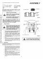
ASSEMBL
Know
Y
Your Tractor
READ THIS OWNER'S
MANUAL
BEFORE OPERA TING YOUR GARDEN
TRACTOR°
If you understand the machine
and its operation,
you will achieve
efficient
and peak performance.
While reading
the manual,
compare
the illustrations
with your Garden Tractor
to familiarize
yourself
with the location of various
controls
and adjustments.
Study
the operating
instructions
and safety
precautions
thoroughly
to insure proper
functioning
of your Garden
Tractor
and to prevent
injury
to yourself
and others° Be sure to pay strict attention
to all notes and cautions;
they are included
for your safety. Save this manual
for future
reference.
another free manual from www.searstractormanuals.com
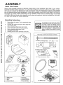
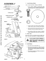
Unpacking
Instructions
1
Remove items from carton
shown below
2
Cut down four corners of the carton with a utility knife
and fold down sides.
Remove banding holding mower deck to skid.
Lower mower deck to floor and remove packing
Remove banding holding tractor to skid
Disengage Parking Brake
Carefully guide the tractor backwards off the skid
3
4
5.
6.
Z.
The box contains the items
The operation
of any tractor
can result in
foreign objects thrown into the eyes, which
can result in severe eye damage
Always
wear safety glasses
or eye shields
before
starting
your tractor and while mowing,
We
recommend
Wide Vision Safety Mask for
over the spectacles
or standard
safety
glasses, available at Sears Retail or Catalog
Stores.
Parts
Bag Contents
@
Not
Shown
Full
Size:
Illi{It_IJillflHHIt{III{fttI{IHIiltH_IIH IILL[I
(2) Battery
Carriage
Bolts
Terminal
15 o Slope
Instruction
- I/4
- 20
x 7 - I/2
Guard
Sheet
(2) Keys
G
Steering
H,
Eo
A. Battery Acid
Bo Battery
C, Seat
D, Owner's Manual
E.
F.
G.
H,
Parts Bag
Steering Wheel
SteeringAdapter
Steering Sleeve
V-Belt
(6) Battery Caps
Wheel
Cap
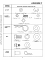
ASSEMBL Y
ASSEMBL Y
LOCA TION
PARTS
BAG
CONTENTS
SHOWN
FULL
SIZE
BA TTERY
another free manual from www.searstractormanuals.com
(2) Lockwasher,
1/4 Int/Ext
Tooth
(2) Wing Nut - 1/4 - 20
©
BA TTER Y
TERMINALS
12) Hex Nut,
©
1/4 - 20
12) Hex Bolt, 1/4 - 20 x 3/4
(2) Lockwasher
1/4
12) Washer 9/32 x 5/8 x !6 Gao
SUSPENSION
ARMS
14) Spring Retainer
(4) Washer
17/32 x 1 _ 1/!6 x !3 Ga.
SEAT
(I) Flex Bolt
1/2 _ 13 x 1 Grade 5
(I)
GAUGE
WHEELS
Shoulder Bolt
(t)
Lockwasher
1/2
(1) Washer 15/32 x 1 x 16 Ga..
(I) Washer t7/32 x 1-3/16
x 12 G&
To assembleandadjustyourtractoryou will need:
ti
_I
(2)
7/16"
wrenches
(2)
1/2'"
(1)
9/16"
wrench
Screwdriver
(1)
3/4"
wrenches
Utility
Knife
Tire Pressure
wrench
Gauge
NOTE: RIGHT HAND (R.H.) AND LEFT HAND (L.H.) ARE
DETERMINED
FROM OPERATOR'S
POSITION
WHILE
SEATED ON THE TRACTOR,
another free manual from www.searstractormanuals.com
WEAR
ASSEMBL Y
VENT
CUT
AWAY
EYE AND FACE SHIELD.
BATTERY
TUBE
MEDIATELY
IF ACCIDENTALLY
IN CONWASH
HANDS
OR CLOTHING
IMTACT WITH
ELECTROLYTE.
BATTERY
CELL
DO NOT SMOKE, FUMES FROM CHARGED ELECTROLYTE
ARE EXPLOSIVE.
FIGURE
NOTE: THIS TRACTOR
IS EQUIPPED WITH AN
OPERATOR PRESENCE SENSING SWITCH. ANY ATTEMPT BY THE OPERATOR TO LEAVE THE SEAT WITH
THE ENGINE RUNNING AND ATTACHMENT CLUTCH
ENGAGED WILL SHUT OFF THE ENGINE°
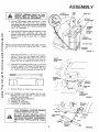
1.
Prepare
Battery
SEAT
SHOULD[
BOLT
b
c,
Fi!l and charge battery (before instalhng)
NOTE: S EE
DETAILED
INSTRUCTIONS
PACKAGED
WiTH
BATTERY VENT CAPS FOUND IN BAG OF PARTS.
Fill battery
with
battery
acid to bottoms
of tubes
in cells (Fig 1). NOTE: DO NOT OVERFILL
OVERFILLING WILL RESULT IN DAMAGE
TO TRACTOR
Check level of battery
acid after 30 minutes.
Add
additional
battery
acid if necessary
NOTE: TIGHTEN
VENT CAPS SECURELY
d _ Charge
hour
battery
at the
rate
of six amperes
for
ADJUSTMENT
'BOLT
2.
Instafl Seat
Seat position
should be adjusted
forward
or back ward so that
the operator
can comfortably
reach Clutch/Brake
Pedal and
safely operate
the tractor (Fig 2)
a
b
c
d
e
Place seat on seat pan. Screw
he_: head machine
screw. Iockwasher
and flat washer into seat (Fig 2)
Screw shoulder
bolt and flat washer into ,seat (Fig 2)
Machine
screw, shoulder
boll and washers
found in
bag of parts (shown full size on page 6)
Tighten
shoulder
bolt and flat washer
using a 1/2""
wrench
Tighten
he_ bolt (adjustment
boll), Iockwasher
and
flat washeJ using a 3/4 _" wrench
Place seat in operatingposition
Sit on the seat and
press clutch/brake
pedal aH the way down
if operating position
is not comfortable,
adjust seat
To adjust
Raise
seat to desired
securely
seat. Loosen adjustment
bolt
position
Tighten
adjustment
FUEL
TANK
\
CLUTCH
BRAKE
PEDAL
FIGURE
one
e o Neutralize
excess battery
acid for disposal
by adding it to four inches
of water in a five gallon plastic
container
Stir with a wooden or plastic paddle whde
adding baking soda until the addition
of more soda
causes no more foaming
Sfide
bolt
I
PAN
READ INSTRUCTIONS INCLUDED WITH
THE BA TTERY CAPS FOUND IN BAG OF
PARTS°
ALWAYS
WEAR GLOVES,
CLOTHING AND GOGGLES TO PROTECT
YOUR HANDS, SKIN AND EYES.
a,
CAP
VIEW
WASHER
ASSEMBL"t
MUS"i" BE TIGHTENED
THE
MACHfNE
SCREW,,LOCKWASHERFLAT
SECURELY TO PREVENT MOVEMENT
OF SEAT,_
2
ASSEMBL Y
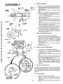
3,
Install
NOTE:
STEERING WHEEL CAP
a
HEX BOLT ---------LOCKWASHER
2 - 3t8"
Steering
POSITION
Wheel
FRONT
WHEELS
FORWARD,
Use a 9/16"
wrench
to remove
hex bolt,
lock washer and 2-3/8"
diameter washer (shown
full size below) from steering column
(Fig. 3),,
DIA,, WASHER
another free manual from www.searstractormanuals.com
STEERING WHEEL
©
STEERINGWHEEL ADAPTER
SLEEVE
STEERING
SHAF_
FIGURE 3
HOOD
BATTERY
COMPARTMENT
b.
Position
sleeve
Position steering
over
steering
shaft
assembly.
wheel over steering wheel adaptor.
c, Secure steering wheel to steering shaft using hex bolt,
/ockwashet and 2-3/8" diameter' washer (Fig. 3)
d. Snap steering
wheel cap in place on steering
wheel. Steering wheel cap found in bag of partsv
4o
Check Tires
Reduce tire pressure to 14 PSI in front and 10 PSI in rear
tires,, (Tires were overinflated
for shipping
purposes).
GRILL
DO NOT SHORT BATTERY TERMINALS.
FIGURE 4
BEFOREINSTALLING BATTERY, REMOVE
METAL BRACELETS,
WRISTWATCH
BANDS, RINGS, ETCo
NUT
5.
WASHER
Install
Battery
a.
hood
Lift
from
rear sides
(Fig.. 4).
b o Remove tape from plastic tray. Make sure drain
tube (Fig. 5) is fastened
to drain hole in battery
tray and battery tray is positioned
in hole of battery support.
c. Place battery in plastic tray (Battery terminals to
front of tractor)(Fig. 5).
HEX
BO LTS
BLACK
{NEGATIVE)
CABLE
FIGURE
5
DRAIN TUBE
8
ASSEMBL
INTJEXT,
WING
NUT
Y
WING NUT
NECTED
TO PREVENT
SPARKS
POSITIVE FIRST
TERMINAL
MUST BE
CONFROM ACCIDENTAL GROUNDING°
INTJEXTr
LOCKWASHER
d,,
another free manual from www.searstractormanuals.com
e,
Connect RED battery cable to positive (+) battery
terminal
with
hex
bolt,
flat
washer,
/ockwasher and hex nut(shown
full size on page 6}
found in bag of parts (Fig 5} Tighten securely with
two 7/16"
wrenches
_IINAL
ACCESS
DOOR
TERMtNAL
GUARD
Connect BLACK ground cable to negative I-) battery
terminal
with
remaining
hex bolt,
flat
washer, Iockwasher
and hex nut (shown full size
below)
found in bag of parts (Fig, 5) Tighten
securely.
TERMINAL
ACCESS DOOR
BATTERY BOLT
NOTE: IF YOU HAVE A WEAK BATTERY, SEE "STARTING YOUR TRACTOR WITH A WEAK BATTERY"
PAGE
21
SUPPORT
FIGURE
f,,
g_
6
Using the slotted hole on one side of the battery
support (Fig. 6) insert one battery bolt, head of
bolt down Fasten the battery bolt to the terminal
guard using int /ext
Iockwasher and wing nut
(.shown full size on page 6) as shown in Fig 6
Assemble the remaining battery bolt to other side
of battery support
and fasten terminal guard to
it with remaining
int /e×t, Iockwasher
and wing
nut Tighten wing nuts securely by hand (Fig 6)
MOWER
SUSI
ARM
.. MOWER
' BRACKET
/
RELEASE
y
h. Remove
Plastic
on tractor
hood
and close,
FRONT
SUSPENSION
BRACKET
NOTE: USE TERMINAL
ACCESS DOORS (FIG. 6) FOR:
1_ INSPECTION
FOR SECURE
CONNECTIONS
(TIGHTEN HARDWARE)
2, iNSPECTION
FOR CORROSION
3_ TESTING BATTERY
4, JUMPING
(IF REQUIRED)
5, CHARGING
(IF REQUIRED)
_GURE
o
0
©
KEEP TERMINAL
ACCESS
DOORS
CLOSED WHEN NOT IN USE.
7
RETAINER,
SPRING
o
BRACKET
DO NOT START
ENGINE
UNTIL
MOWER
SUSPENSION
BRACKET
HAS BEEN RELEASED. SEE MOWER
DRIVE BELT INSTALLATION,
PAGE
10.
SUSPENSION
ARM
WASHER
LIFT
LINK
STUD
RETAINER
SPRtNG
9
FIGURE
8
6_
ASSEMBL Y
MOWER DRIVE
BELT
another free manual from www.searstractormanuals.com
PRIMARY
MANDREL
FIGURE
FRONT
SUSPENSION
BRACKET
RETAINER
-_-
SPRING
GAUGE
WHEEL
\
Installation
a,
b
PARALLEL
LINK
ASSEMBLY
9
WHEEL
GAUGE /
BAR
Mower
BRACKET
,
Remove band from mower suspension
bracket.
Remove banding from suspension
arms (Fig. 7)
and gauge wheels, Set gauge wheels aside for
later assembly°
c, Slide mower under tractor,
deflector
to R,,H,,
side_
do Slide front suspension
brackets
into mower
brackets,
Retain with release pins (Fig, 7),
e o Turn height adjustment
knob counterclockwise
( _
) until it stops (Fig 7)
Push attachment
lift switch to lower mower suspension links (page 11).
g,
Slide studs through lift finks on both ,sides of
tractor (Fig 8J Retain with washers and retainer
springs (shown full size on page 6) found in bag
of parts
h, Place the suspension
arms on brackets on both
sides of frame (Fig 8) Retain with washers and
retainer springs found in bag of parts,
i,
Turn height adjustment
knob (Fig 7) clockwise
(,'_
) to remove slack from mower suspension
j.
Roll drive belt over primar y mandrel (Fig 9)
k
Insert gauge wheelbar into bracket, Retain with
clevis pin and retainer spring [shown full size on
page 6) found m the bag of parts (Fig 10) Repeat
for other gauge wheel
Mower
Drive Belt Installation
a,
b,
FIGURE
Remove hood and grill (See page 23L
Place mower drive belt over clutch pulley and
under idler pulley and tension pulley (Fig 11).
NOTE: PULL LEVER
FORWARD
TO SWING
TENSION
PULLEY
FOR BELT CLEARANCE
Make sure narrow "V" side of belt is engaged in
each pufley(Fig.
11)
c, Pull mower drive belt over front mower suspension
bracket (Fig 7),
d ,_ Replace hood and grill.
CLEVIS
PIN
10
CLUTCH
PULLEY
8.
Mower
Drive Belt Adjustment
a.
b.
Lower mower using attachment lift switch.
If dimension
"A"
on idler bracket
assembly
measures
1/4" or less, mower drive belt must
be adjusted
(Fig 1 1-tnset)_
c.. Turn ignition switch off and remove mower drive
belt,
do Using two 9/16"" wrenches,
remove bolt, (2)
washers, Iockwashet
and nut #om idler pufley
(Fig. 1 l-Inset)
(original position),
e
Place v-belt and idler pufley #_ "NEW"
pulley
position
(Fig.
114nset)..
Replace
bolt,
(2)
washers, Iockwasher
and nut. Tighten securely,
f . Check v-belt for proper installation
on all pulley
grooves,
TENSION
PULLEY
_GURE
ti
9.
Check
the Cutting
Level
The blade housing was set at the factory to cut level.
After mowing a short distance, look at the area that was
cut, If the blade housing cuts uneven; see the instructions on "Side-to-Side And Front-to-Rear Mower Adjustment"
(page 23)"
10. Final Assembly
IDLER BRACKET
ASSEMBLY
PULL FORWARD
TO LOOSEN BELT
FOR EASIER BELT
INSTALLATION
J
a.
b,
10
c_
Make sure all fasteners
are tight,
Read and follow
the operation
instructions
(page 1 1). Know the location
and purpose
of
all controls..
Check oil and.gasoline (page 12) before starting the
tractor
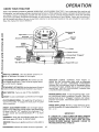
OPERA TION
KNOW
YOUR
TRACTOR
another free manual from www.searstractormanuals.com
READ THIS OWNER'S
MANUAL
BEFORE OPERATING
YOUR GARDEN TRACTOR
If you understand
the machine and
its operation,
you will achieve efficient
and peak performance,
Whfe reading the manual, compare the illustrations
with
you Garden Tractor to familiarize
yourself with the location
of various controls and adjustments.,
Study the operating
instructions
and safety precautions
thoroughly
to insure proper functioning
of your Garden Tractor and to prevent
injury to yourself and others. Be sure to pay strict attention
to all notes and cautions;
they are included
for your safety
Save this manual for future reference
Attachment
Switch
Attachment
Hourmeter
Clutch
Indicator
Lights
Ignition
Switch
Clutch/Brake Pedal
Height
Adjustmen_
Knob
Gear Shift
Lever,
THROTTLE
CONTROL:
Use the throttle
control
crease or decrease
the speed of the engine°
to in-
ATTACHMENT
CLUTCH SWITCH:
Pull switch out and
up to engage attachment.
There wi!l be an engine hesita_
tion as the clutch engages.
INDICATOR
LIGHTS:
"DEPRESS
FOOT
PEDAL"
indicates that the clutch/brake
pedal must be depressed
before
engine
will start, "DISENGAGE
ATTACHMENT"
indicates that the attachment
must be disengaged
before
the engine will start, "CHECK OIL" is a low oil pressure
warning fight "BATTERY DISCHARGING"
indicates there
is insufficient
battery charging
ATTACHMENT LIFT SWITCH: Use the attachment lift switch
to raise and lower the attachment mounted to your tractor.
LIGHT
Lift
SWITCH:
CHOKE:
Turns
on and off
To start a cold engine,
the headlights.
PARKING BRAKE LOCK: To set the parking brake, push
the clutch/brake
pedal completely
forward°
Place the
parking brake lever in "Engaged"
position
and release
pressure
from pedal. Clutch/brake
pedal will remain in
brake position
pull choke out to engage
CLUTCH/BRAKE
PEDAL: The pedal has 2 functions,:
a
clutch and a brake To engage the brake push the pedal
down completely
RANGE SHIFT LEVER: The Hi-Lo range shift lever gives
you the versatility of 6 speed selections: Lo 1, 2, 3, and
Hi 1,2,3,
HEIGHT ADJUSTMENT
KNOB: Use the height adjustment knob to adjust the mower height,, With attachment
rift lever in the full "UP" position,
turn clockwise
(F_)
to raise mower
and counterclockwise
(_)
to lower
mower.
GEARSHIFT:
Press the clutch/brake
pedal down
and move gear shift lever to desired speed.
IGNITION:
start.
Place key in ignition
HOURMETER:
Indicates
IMPORTANT
IF "CHECK
OIL" LIGHT COMES
ON WHILE ENGINE
iS RUNNING,
SHUTTRACTOR
OFF IMMEDIATELY.
RUNNING
ENGINE
WiTH
THIS
LIGHT
ON CAN
CAUSE
SEVERE
ENGINE
DAMAGE,
REFER
TO
TROUBLESHOOTING,
PAGE 25,
firmly
and turn to the right to
the number of hours of operation,
11
OPERA TION
d
Place attachment
clutch
ENGAGED
position
e . Move
throttle
contro!(page
f , Turn ignition
key (page
choke to stop engine
another free manual from www.searstractormanuals.com
ENGINE
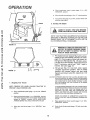
2o Starting
I
_
switch
11)to
(page
11) in
'DIS-
"'S"° (slow) position
11)to'OFF"position
Never
use
The Engine
YOUR
IN ASTOP
LARGE,
OPEN
AREA°
LEARNTRACTOR
TO START,
AND
REVERSE
NOTE: THIS TRACTOR IS EQUIPPED WITH INTERLOCK
SWITCHES TO PREVENT STARTING OF THE TRACTOR
ENGINE WHILE THE ATTACHMENT CLUTCH OR THE
CLUTCH/BRAKE PEDAL IS ENGAGED.
i
FIGURE
12
!
IMMEDIATELY REPLACE SWITCHES THAT
ARE NOT IN PROPER WORKING ORDER,
DO NOT ATTEMPT TO DEFEAT THE PURPOSE OF THESE SWITCHES.
,,,
a,
This engine has been shipped filled with summer
weight oil (for cold weather operation
see Chart
page 16), Check engine oil level with tractor on
level ground. Wipe dipstick (Fig, 12) clean, screw
it in tight for a few seconds, remove and read oil
level. If necessary,
add oil until "FULL'"
mark is
reached,,
See chart
page
16,
b o Fill fuel tank (Fig, 13). Use fresh, clean, regular
unleaded
automotive
gasoline°
(Use of leaded
gasoline
will increase
carbon
and lead oxide
deposits and reduce valve life). Capacity is 3 o1/2
gallons,
CA UTION EXPERIENCE IND1CA TEE THAT ALCOHOL BLENDED FUELS
(CALLED GASOHOL OR USING ETHANOL OR METHANOL)
CAN ATTRACT MOISTURE WHICH LEADS TO SEPARATION
AND FORMATION OF ACIDS DURING STORAGE ACIDIC
GAS CAN DAMAGE
THE FUEL SYSTEM OF AN ENGINE
WHILE IN STORAGE
1. Stopping Your Tractor
NOTE: REMOVE
KEY WHEN LEAVING
PREVENT UNAUTHORIZED
USE,
TRACTOR
TO
a,
Push clutch/brake
position
b
Place parking brake (page 11) in -ENGAGED""
position
and release pressure
from clutch/brake
Pedal should
remain
in "BRAKE"
position,
NOTE,
MAKE
SURE
PARKING BRAKE WILL HOLD TRACTOR IN PLACE
c_
Move
tion
gear
shift
TO A VOID ENGINE PROBLEMS, THE FUEL SYSTEM SHOULD
BE EMPTIED BEFORE STORAGE OF 30 DAYS OR LONGER.
DRAIN THE GAS TANK START THE ENGINE AND LET IT
RUN UNTIL THE FUEL LINES AND CARBURETOR ARE
EMPTY USE FRESH FUEL NEXT SEASON, SEE STORAGE
INSTRUCTIONS FOR ADDITIONAL INFORMATION
pedal (page 11) into full "BRAKE
lever
(page
t 1) to "NEUTRAL"
NEVER USE ENGINE OR CARBURETOR CLEANER PRO*
DUCTS IN THE FUEL TANK OR PERMANENT DAMAGE MAY
OCCUR
posi-
12
C,,
Place attachment
clutch
ENGAGED"
position
d,
Push clutch/brake
position
switch
(page
1 t) in "'DIS-
pedal (page 1 1) fully into brake
-
e.
Pluc¢
g,:ar
;hi't
lever
f.
Place
(page
range
1 1/
g.
Pull choke out (page t 1)
h,
Move throttle
shift
in "'N'
lever
control
in
neutral(page
11)
"N""
position
to middle
neutral
position
OPERA ON
(page 1 1)
another free manual from www.searstractormanuals.com
Turn
ignition
to "START"
position
until
engine
starts
(page
11). NOTE
DO NOT RUN STARTER
CONTINUOUSLY
FOR MORE
THAN FIFTEEN
SEC-
j.
ONDS
several
sition,
PER MINUTE
If engine
does not start after
attempts.,
move
throttle
control
to "'F'" powait a few minutes
and try again
After
engine
is warm,
push
choke
in
RETAINER
" SPRING
The first time you start the engine, it will take extra
cranking
time to move fuel from tank to engine,, NOTE:
ALLOW ENGINE TO WARM UP FOR A FEW MINUTES
BEFORE ENGAGING
CLUTCH/BRAKE
PEDAL OR ATTACHMENT
CLUTCH SWITCH
S
J
\..
CLEVIS PiN
GAUGE WHEEL _
k o When restarting
a warm engine, move throttle
control
midway
between
"S'" (stow) and "'F'"
(fast) position,
Choke may not have to be used,
3.
Your Tractor
15
and Mower
NOTE: THIS TRACTOR
IS EQUIPPED WITH AN
OPERATOR PRESENCE SENSING SWITCH ANY ATTEMPT BY THE OPERATOR TO LEAVE THE SEAT WITH
THE ENGINE RUNNING AND THE ATTACHMENT
CLUTCH ENGAGED WILL SHUT OFF THE ENGINE,
BEFORE
DRIVING
THE TRACTOR,
INSTALL
MOWER
OR REMOTE
FRONT
PARALLEL
LINK ASSEMBLY
AND RAISE MOWER
SUSPENSION
ARMS
TO HIGHEST
POSITION
(Fig° 9)_
_
Operating
FIGURE
READ THE
"SAFETY
BEFORE
OPERATING
WARIXIIlXIG
RULES"
CAREFULLY
YOUR MOWER°
1 o Keep all shields in place,,
2
b _
Co
d.
e,
3.
Depress clutch/brake
pedal and set parking
Disengage
attachment
clutch switch.
Shut off engine.
Remove ignition
key,
Wait
for
machine_
all
4., Keep people
machine,,
5,
Use the hetght
adjustment/<nob
(page 1 1) to adjust
mower
height
Move the attachment
lift switch
to the full "°UP"pos/tion,
turn height
adjustment
knob clockwise
(--_) to raise
cutting
height
and counterclockwise
(,_--) to lower
cutting
height
Fully lower
attachment
to check adjustment
Before leaving operator's
position:
a Shift transmission
to neutral,
movement
and pets
to stop
a safe
before
distance
brake
servicing
away
from
c.
Move gauge wheels to the adjustment
hole that
will provide the desired cut,
Replace retainer spring and clevis pin
With engine running and warm, place throttle control midway
between
"S" (slow) and "F" (fast)
position (page I 1)
Move attachment
to _ts full "'UP-position
t3
gauge
retainer
wheels
spring
(Fig
range
1 1)
shift
15) lower
and clevis
To engage mowerpullattachment
(page 1 1) out and up
h o Move
(page
ATTACH-
DO NOT ADD ADDITIONAL WEIGHT
TO THE TRACTOR OTHER THAN THE
OPTIONAL WHEEL WEIGHTS,
EXCESSIVE WEIGHT MAY OVERLOAD
AND DAMAGE THE TRANSMISSION.
Remove
wheels
g
DO NOT OPERATE THE MOWER WITHOUT
THE DEFLECTOR SHIELD IN PLACE.
CAUTION:
b
f
NEVER PLACE YOUR HANDS OR FEET IN
OR UNDER ANY POWERED ATTACHMENT
OR NEAR ANY
MOVING
PART WHILE
POWERED
To adjust
ment
d.
e
Always
wear substantial
footwear
and avoid loose
fitting clothing that could get caught in moving parts
TRACTOR
OR ANY
MENT IS RUNNING.
a.
lever
attach-
pin from gauge
clutch
to "'LO °" flow)
switch
position
i.
/
Move gear shift lever to deslred gear (page 1 1)
Use attachment
lift switch to lower mower into cutting position.
k.
Release clutch/brake
movement.
I.
Start mowing
by increasing
at slow
throttle
pedal
SLOWLY
to
start
and increase ground
speed
as conditions
will permit.
NOTE: BRING TRACTOR TO COMPLETE STOP BEFORE
SHIFTING GEARS.
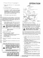
4o Mowing
OPERA TION
Normal
Mowing
NOTE: TiRE CHAINS
CANNOT
MOWER HOUSING ATTACHED
GEARSHIFT
FUNCTION
a
1H or 2L
m
another free manual from www.searstractormanuals.com
b.
IL
Tilling
1L
Dozing
1L
Grading
2L
Transport
3H
FAST
SLOW
• Indicates Range Shift Lever position:
"H" for High, "L" for low
Use the runner on the RH.. side as a guide; the
blade cuts approximately
an inch outside the runner (Fig. 17).
Drive so that clippings
are discharged onto the
area that has been cut. Have the cut area to the
5o Operating
a.
R Ho RUNNER
I
The Tractor
Choose the lowest
down hills.
d.
e.
......
- --,---,---
L____
---. -.______
_
ii ]
......
pli_ll1,1111t_
)it
......
up or
Avoid
stopping
or shifting
is necessary,
position.
move
on hills.
throttle
control
lever
TOR ROLL DOWNHILL AS CLUTCH/BRAKE
AND STARTING TO ALLOW SLIGHT TRACPEDAL MOVES
THROUGH
CLUTCH
POSITION.
_
.
starting
LEAVE ENOUGH ROOM WHEN STOPPING
GUARD
17
,._
gear BEFORE
i
c . If slowing
to middle
DISCHARGE
On Hills
DO NOT DRIVE UP OR DOWN HILLS WITH
SLOPES GREATER THAN
15 ° AND DO
NOT DRIVE ACROSS ANY SLOPE. REFER
TQ pAGE 51.
b.
FIGURE
THE
right of the machine.
This will result in a more
even distribution
of clippings
and more uniform
cutting.
c .. When mowing large areas (Fig. 78), start by turning to the right so that the clippings
will be
discharged away from shrubs, fences, driveways,
etc After two or three rounds, mow in the opposite
direction
making
left hand turns
until
finished.
d.. If grass is extremely
taft, it should be mowed
twice_ The first time cut relatively
high. The second t#ne to the desired height°
e. The left hand side of mower should be used for
trimming.
SLOW-FAST
FIGURE 16
WITH
BEFORE
OPERATING
YOUR
MOWER°
READ THE "SAFETY
RULES" CAREFULLY
REFER TO PAGE 2o
2H _ or 3L _
snow
Removal
BE USED
THROTTLE
1
Heavy
Mowing
'Tips
f,
.,
llllll
FIGURE 18
14
If stopping
is absolutely
necessary,
push
clutch/brake
pedal quickly to brake position and
engage parking brake_
To restart your tractor, make sure tractor is in 1st
gear and that you have allowed room to roll slightly downhill.
Disengage parking brake and release
clutch/brake
pedal SLOWLY to start tractor forward movement.
Make all turns slowly°
I
I
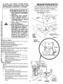
INTENANCE
another free manual from www.searstractormanuals.com
To keep your tractor running better,
longer, perform necessary service using
the foflowing maintenance
schedule:
g
h
BEFORE MAKING ANY INSPECTION,
ADJUSTMENT OR REPAIR: {FIGo 19):
1_ PUSH TRACTOR CLUTCH!BRAKE
PEDAL COMPLETELY INTO BRAKE
POSITION°
2. MOVE GEAR SHIFT CONTROL
LEVER TO NEUTRAL POSTION
3, PLACE
PARKING
BRAKE
IN
"ENGAGED POSITION° REMOVE
FOOT FROM PEDAL.
4. TURN
OFF
ATTACHMENT
CLUTCH SWITCH,,
5_ SHUT OFF THE ENGINE,,
6o MAKE ABSOLUTELY SURE THE
BLADES AND ALL MOVING PARTS
HAVE COMPLETELY STOPPED°
7_ DISCONNECT THE SPARK PLUG
WIRES FROM THE SPARK PLUGS
AND KEEP WIRES AWAY FROM
THE SPARK PLUGS TO PREVENT
INJURY
FROM
ACCIDENTAL
STARTING°
BE CAREFUL TO
AVOID TOUCHING HOT ENGINE
OR MUFFLER COMPONENTS.
With oil in crankcase, start engine and check for leaks
around the filter element Retighten only as much as
necessary to efiminate leaks Do not overtighten
Shut down engine and re-check oil level Add as
necessary to bring up to full mark,
ATTACHMENT CLUTCH SWITCH
"OFF"
POSITION
IGNITION
KEY
CLUTCH/
BRAKE
PEDAL
"BRAKE"
POS|TION
ARK1NG BRAKE
"ENGAGED"
POSITION
"_
/
FIGURE I9
ENGINE OIL
DIPSTICK
AND FILL TUBE
With Every Mowing
1, Make sure all nuts on bolts are tight and cotter pins and
retainer springs are secure
2., Observe all safety precautions
3, Keep Tractor well lubricated (refer to page 18_
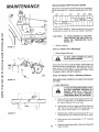
First Two Hours (Two Mowings)
1,, CHANGE ENGINE OIL
Changing off after the first two hours (or two mowings)
will help eliminate
break-in
residue which might be
damaging to your engine.
NOTE:' BE CAREFUL NOT TO ALLOW DIRT TO ENTER
THE ENGINE WHEN CHANGING OIL
a, Drain oil with engine warm
b, Remove hood and grill (see page 23)
c, Loosen oil drain wing nut (Fig 20) Catch oil in a
suitable container
and dtscard
d, Tighten oil drain wing nut after all oil has been
removed from engine
e, Refill engine oil, Refill capacity is 3 pints without filter
change
NOTE: DO NOT OVERFILL
f, Replace dipstick,
FIRST 25 HOURS
1,_ CHANGE ENGINE OIL AND OIL FILTER (INITIAL BREAK-IN
CHECK)
Refer to Service Record, Page 19 for oif filter change interval
If operating in extremely dusty conditions, change oil filter more
often,
a
Drain oil and discard.
b
Spin off oil filter element and discard
c
Thoroughly clean filter mounting surface and make sure
new gasket is inserted in the element
d
Apply a thin film of off to the gasket
e
Spin element down by hand until gasket just touches
mounting pad Then turn down an additional _-V2 turn
Do not overtighten
f
Refill engine oil, Refill capacity is 3V2 pints with oil filter
change
15
011 Filter
OIL DRAIN
WING NUT
FIGURE
20
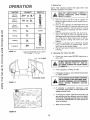
MAINTENANCE
Recommended
SAE
Viscosity
Grades
Determine temperature expected before next oil change,
All oil must meet A.P,L, service classification SD, SE or
SHIFT
COVER
SF_
_20 °
0°
32 °
,,,,,,
60 °
80 °
I l I IlL
30 or 10W-30
100 °
L,,
J
5'W-30
NOTE: DO NOT OVERFILL Dipstick assembly must be securely tightened into tube at all times when engine is operating.
another free manual from www.searstractormanuals.com
\
TO AVOID DAMAGE TO THE STARTING SYSTEM,
USE SAE 5W30
OIL
WHEN
THE TEMPERATURE
FALLS
BELOW32°o
CAUTION:
f
FIGURE 2 t
Replace dipstick.
Every
1
5 Hours
Check
(Five
Mowings)
Engine Oil Level
WITH
ENGINE
RUNNING.
DO NOT
CHECK
ENGINE
A_
OIL LEVEL
Several minutes after stopping engine, check engine oil
level with tractor' on level ground.. Wipe dipstick (Fig. 20)
clean, screw it down tight for a few seconds,
remove
and read oil level. If necessary,
add oil until "'FULL" mark
is reached,
NOTE: DO NOT OVERFILL
Every
Hours
(Twice
(Operating in dusty conditions
set vicing° }
FIGURE 22
I,
:
Brake
CENTER
/,HOLE
a,
0 ........
I\!:
'
BLADE
a Mowing
Season)
may require more frequent
Adjustment
IF TRACTOR
REQUIRES MORE THAN
SiX FEET STOPPING
DISTANCE
IN
HIGHEST
GEAR ON A LEVEL DRY
CONCRETE
OR PAVED
SURFACE
THEN BRAKE MUST BE ADJUSTED.
t
i
FIGURE
25
_
\
1
b_
23
c,,
d_
e
16
Remove (4) hex washer head tapping screws from
shift cover plate (Figr 21), located on top of tractor frame, Remove the cover plate,
Loosen jam nut (G) on brake rod (B) at clevis (c)
(Fig.. 22) If you find it difficult
to loosen jam nut
(G), remove cover plate in L.H.. frame rail.
Rotate brake rod (B) counterclockwise
(,#-'_) tur _
ning brake rod out of clevis (C) four to six turns.
Start tractor
position
with
Depress clutch/brake
stops moving.
tramsmission
in "'N'"
pedal to the point
(neutral)
where belt
f _
MAINTENANCE
Engage parking brake to hold clutch/brake
pedal
in position.
If belt begins to move after engaging
parking brake, depress clutch/brake
pedal to next
notch on parking brake.
VENT CAP
CUT
g.
AWAY
VIEW
Shut engine off., Rotate brake rod (B) clockwise
(f'-_",) by hand, turning brake rod into clevis (C),
until tight_ Tighten jam nut (G) on brake rod. (t9)
at clevis (C) [Fig. 22).
BATTERY
'TUBE
h o Reinstall
shift cover plate and four (4) mounting
screws
Replace cover plate/fremovedin
step (b)
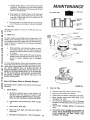
2.
BATTERY
CELL
Tire Care
another free manual from www.searstractormanuals.com
FIGURE
Maintain
tire pressure
at 10 PSI.
in front at
24
14 PSI and rear tires
_NUT
3,
Blade Care
INNER
SAFETY
For best results mower
blades must be kept sharp_ The
blades can be sharpened
with a few strokes of a file or
on a grinding wheel, We suggest they be sharpened after
every 25 hours of mowing°
Do not attempt
to sharpen
while on mower,
a.
b_
COVER
COVER
ELEMENT
COVER
POLYURETHANE
PRE-CLEANER
PAPER
ELEMENT
When grinding, care should be taken to maintain blade balance
and the blade should
be
checked for proper balance before reinstallation
on mower
Unbalanced
or bent blade will cause excessive
vibration when running and eventual damage to
mower
or engine,
Replace bent or damaged
blades.
BASE
FIGURE 25
To check blade balance, drive a nail into a beam or wall.
Leave about one inch of the straight nail exposed.. Place
center hole of clean blade over the head of the nail (Fig.
23). NOTE: CENTER HOLE OF BLADE ON NAIL IF
BLADE IS PROPERLY BALANCED, BLADE SHOULD REMAIN IN POSITION SHOWN IN FIG. 23. IF EITHER END
OF THE BLADE MOVES DOWNWARD, BLADE IS NOT
BALANCED, SHARPEN THE HEAVY END UNTIL THE
BLADE IS BALANCED°
Every
50 Hours
(Once
a Mowing
Season)
(Operating in dusty conditions may require more frequent
servicing)
1.
Check
a.
FIGURE 25A
2,
Battery
a, Unscrew knob (Fi# 25) to remove cover.
b. Remove polyurethane pre-cleaner
Electrolyte
solution
level in each battery
cell
should be even with bottoms
of tubes in cells
(Fig. 24). Add only distilled water if necessary°
NOTE: DO NOT OVERFILL, DO NOT ADD ACIDo
b o Keep battery
78.
battery
and terminals
co
Keep
bolts
d,
Keep vent caps
caps open.
e.
Recharge
c. Wash foam pre-cleaner in detergent and water,
d .. Rinse, squeeze (rather than twist) allow to dry
throughly° (Fig. 25A)..
e. Coat with three tablespoons of S.A.E. 30 engine
oil squeeze to distribute evenly and squeeze out
excess°
f o Check paper c_rtridg#. !_eplace ff excessively
dirty.
clean° Refer to page
tight.
tight
at 6 amperes
and small
vent
holes
for t hour if necessary,
Clean A# Filter
in
17
go Reassemble paper cqqri#ge and re-position on
tractor. NOTE: NEVI_R _!qN ENGINE WITH AIR
FILTER REMOVED AS-plRT
(DUS}T) WILL
DAMAGE THE ENGINE.
MAINTENANCE
4o
3.
The best time to drain engine oil is at the end of a day's
operation when all dirt and foreign materials are suspended in the hot oil,, Refer to page 15.
Clean Battery
and Terminals
Corrosion and dirt on thebattery
and terminals cause the
battery to "leak" power and hinders the operation of the
charger
a_ Remove terminal
guard.
€,
Clean terminals
until
d,
6.
and cable ends with a wire brush
with
plain
water,
dry
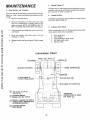
Lubrication
WHEEL
Lubricate
a.
b,
c.
d.
eo
and
e o Replace cables and terminal guard. Refer to page
8.
@
Change Oil Filter
where
Front Axle Pivot
Hood Hinges
Foot Pedal Shaft (both ends)
Lift Shaft (both ends)
Steering
Plate
Chart
SPINDL E
PINDL
@
-WHEEL
;_
BEAt
BEARINGS@
ENGINE(_
Q
BOTH
FOOT
" SECTOR
ENDS OF
PEDAL
SHAFT
--
BOTH
_(_ 'SAE 30 (SD, SE OR SF)
MOTOR OIL
--
CHASSIS GREASE
SEARS PART NO, 2557R
GEAR
ENDS
LIFT SHAFTQ
TRANSAXLE
(CHECK LEVEL AT REAR
FILL PLUG)
Q
REFER TO ENGINE OIL SPEC'S,
{UNDER INITAL PREPARATION
'IN OWNERS MANUAL)
Q
CHASSIS GREASE
WITH BRUSH
:
18
oil filter
Pivot Points
Place severa! drops of S_A,,E, 30 oil at points
move against each other, especially:
bright,
Rinse the battery
reinstall
on tractor,
Engine Off
If operating in extremely dusty conditions, change
more often. Refer to Page 15_
Remove the battery from the tractor and wash
with four tablespoons
of baking soda to one
gallon of water, NOTE: BE CAREFUL NOT TO
GET THE SODA SOLUTION
INTO THE CELLS,,
b,
another free manual from www.searstractormanuals.com
5o
Change
Q
parts
MAINTENANCE
7,
Clean Air Screen
Air screen (Figs 26) must allow free-flow
of air to prevent engine damage from overheating
Clean with a wire
brush or compressed
a# to remove
dirt, stubborn
dried
gum and fibers.
8,
Clean Fro_t Grill
MUFFLER
Brush debris from front grill to a/low free-flow
preventing
engine damage from overheating
another free manual from www.searstractormanuals.com
9.
of air,
Lubricate Steering and Front Wheels
There are four grease fittings on your tractor
(Fig, 27),
Using a grease gun, give each grease fitting two shots
of chassis grease (available
through your Sears Service
Center)_ Sears Part No 2557R
AIR
SCREEN
FIGURE
I
26
FRONT
10,_ Check Muffler
Inspect and replace
a fire hazard and/or
EVERY
100
corroded muffler
engine damage
HOURS
(Every
as it could
Two
_==_o
create
Years)
IN
DISCONNECT
SPARK
PLUG
_,vOT
]lI
WIRI_S
AREA
OF
GEAe
TO PRE-_
SECTOR
._
"_
FRONT
WHEEL
",OREA,EFl
,,N ,
HGH_
VENT
ACCIDENTAL
STARTING
BEFORE MAK-_
ING ANY
INSPECTION,
ADJUSTMENT
OR I
REPAIR
(EXCEPT
FIGURE 27
CARBURETOR).,
J
Replace
Spark
Plugs
Replace spark plugs at the beginning
of each season
every 100 hours, whichever
comes first, Gap should
set at
,025" inch (Fig, 28)
2o Replace A# Filter
Refer to page 17,
Paper
or
be
""
'
-
Cartridge
_,J'_l
-
.025
FEELER
,'91K. G,.aE
SPARK
_
,
FIGURE 28
SERVICE RECORD
SERVICE
RECORD
SCHEDULE
FIRST
2
HOURS
FilI in dotes a_, you complete regular service
FIRST
2,1_
HOURS
EVERY I EVERY
5
25
HOURS
HOURS
Ig_ades
X
Brake
x
Adjustmem
Check
Ballety
Change
Engine
Oil
,
X
,
I EVERY
EVERY
I
50
100
} HOUR S HOURS
1
X
1
X
F
Check
Clean
Engine Oil Level
Ai_ C_eanel
Check
X
Element
i
X
Mulfler
I
X
...........................
L
Clean Air S_roen
X
Clean
X
Ftont
Lubricale
G_I
Tracto{
X
Replace
Spark Plugs
Replace
Ai( CIeaner
Check
1ire inflation
E}ement
{
X
I
X
p_essure
Change Engine Oil Filter
X
X
19
X
Sears, Roebuck and Co reserves the right to make any
changes in design or improvements
without
imposing
any obligation
to install
the same
upon
its terms
heretofore
manufactured.
1_
Starting
Your Tractor
with
a Weak
Battery
if your battery is too low to start the engine, it should
be recharged
If "jumper cables"
arre used for emergency starting
follow this procedure:
NEGATIVE
(BLACK CABLE}
TERMINAL
NOTE: YOUR TRACTOR IS EQUIPPED WITH A 12 VOLT
NEGATIVE GROUNDED SYSTEM, THE OTHER VEHICLE
MUST ALSO BE A 12 VOLT NEGATIVE
GROUNDED
SYSTEM,
another free manual from www.searstractormanuals.com
BATTERY
LEAD-ACID
BATTERIES GENERATE ExPLOsivE_
A_
GASES. KEEP SPARKS, FLAME AND SMOKING
_._kMATERIALS
AWAY
FROM
BATTERIES°
l ems-m_ALWAYS
WEAR EYE PROTECTION
AROUND
I............ BATTERY_
a.
Connect
each end of the RED cable to the
POSITIVE ( + ) terminals of each battery (taking
care not to short against chassis).
(Fig. 29).
b o Connect
one end of the BLACK cable to the
NEGATIVE
(-) terminal of fully charged battery.
c . Connect
the other end of the cable to L.Ho side
panelbott
(Fig, 19). NOTE: KEEP AWAY FROM
GAS TANK AND BATTERY°
d. Disconnect
cables in reverse order:
1. L.Ho Side Panel Bolt (Fig. 19),
2_ Negative
Terminal
3, Postive Terminals
of fully chargee
f
POSITIVE
(RED CABLE)
TERMINAL
FIG URE 29
Hattery
DO NOT USE YOUR BATTERY
I IMPORTANT: START OTHER VEHICLES.
TO|
J
2. Carburetor
All carburetors
have a fixed main jet An optional main
jet is available for altitude
compensation
above 5,000
feet,
The carburetor
idle mixture
was set for maximum
efficiency
at the factory and should normally
not be
disturbed.
If adjustments
seem necessary, first be sure
the ignition
system is working
properly
and governor
sensitivity is properly adjusted.
The carburetor
has a limited adjustment
range between
stops of +-_ turn, The screw should only be adjusted
within these limits; in to lean the mixture, out to richen,
When replacing
idle mixture screw, turn in until lightly
seated, then turn screw back out 1¼ turns. Replace
limiter cap with the plastic stop approximately
centered,
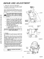
3.
Throttle Control Cable and Carburetor Adjustment
Never attempt to change maximum
engine speed= This
is preset at the factory and should only be changed by
a qualified
service
technician
who has the necessary
equipment.
FIG URE 30
THROTTLE
STOP
SCREW
i
REFER12.
PAGE
TO "STARTING
THE ENGINE",
THROTTLE
ARM "_
IDLE FUEL
LIMITER CAP
20
FIGURE31
ADJUSTMENT
ELECTRIC
another free manual from www.searstractormanuals.com
a
Start the engine and allow it to warm up thoroughly
(at least ! 0 minutes )
b, Loosen clamp screw so throttle cable is free to
move ((Fig. 30),
c,, Move throttle (on dashboard) to "slow" position
d Hold throttle arm against stop screw and adjust
throttle stop screw to t 000-11 O0 RPM (Fig,, 3 !).
e., Adjust the governor
low speed adjustment
screw
for 1400 RPM idle (Fig,. 30),
f, Tighten
clamp screw
to secure
throttle
cable
FIG URE 32
BELT
4,
ENGINE
PULLEY
......
_
\
"V-
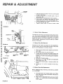
5 • Motion
33
l
IDLER
Clutch
Adjustment
The electric clutch (Fig, 32) should provide years of service. The clutch incorporates
a built-in brake that stops
the pulley almost immediately•
Eventually,
the internal
brake will wear so the mower
blades will not stop as
recommended.
Adjustment
must be made by a Sears
Service
Technician,
LOOSEN
FIGURE
Electric
I
ADJUSTP,BLE
IDLER
The belt on this tractor
is special for this
Always
replace with the Sears belt number
list. It is not necessary
to remove
mower,
,\ _7"77-,
CLU_'CH
Drive Belt Removal
application_
in the parts
a_ Raise hood and disconnect negative ground battery cable,
b. Set parking brake (to get belt slack),
c, Loosen (do not remove) two engine pulley belt
guide bolts and swivel R, H. side of belt guide up_
Tighten L.H bolt to hold belt guide in position
(Fig. 33),
d, Roll belt off engine pulley.
e Rofl belt off "V" idler, flat idler and adjustable
idler pulleys (Fig° 34).
f Pull belt off clutch pulley - between pulley and
frame.
g Loosen nut "'A "" on R_H, outside of frame (Fig.
35),
_
PULLEY
'_v TRANSAXL
_
E
PULLEY
FIG URE 34
SHIW
COVER
PLATE
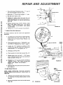
6o Motion
Drive Belt Replacement
NOTE: THERE IS A BELT INSTALLATION DECAL UNDER
L.H FOOTREST,
\
FIGURE35
a, Push bett down from engine pulley area, Place
back (flat) side of belt on flat idler., (Flat idler is
next to frame)°
b. Place belt on adjustable idler and over clutch
pulley_ "'V'" (narrow) part of belt should engage
clutch pufleyo
2t
AND
REPA
Place belt around transaxle
pulley
"V"
belt should engage transaxle
pulley,
C
d. Make
sure
"V'" part
of belt engages
part
of
ADJUSTMENT
©
ENGINE PULLEY
"'V'" idler
another free manual from www.searstractormanuals.com
BELl" GUIDE
e.
Roll belt
f.
Loosen Loll. engine pulley belt guide bolt and
swivel belt guide bolt and swivel belt guide onto R,H. bolt, Tighten L.H, and R, Ho bolts securely
(Fig, 36).
g,
Release parking brake. NOTE: WHEN A NEW
BELT HAS
BEEN INSTALLED,
YOU MUST
CHECK
V-BELT
ADJUSTMENT
AND BRAKE
ADJUSTMENT.
h
7.
over
engine
T/_htennut"A-onR
Motion
pulley
FIGURE
36
H outsideofframe(Fig35)
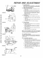
Drive Belt Adjustment
TOP OF
To assure maximum
seasonally
aN
b_
C_
To tighten belt, remove (4) hex washer head tapping screws
from shift cover plate (Fig
35)
located
on top of tractor
flame.
Remow
the
cover plate,
- 1f16"
TOP OF
PIN
Place parking brake lever in "'ENGAGED"
positiono Refer to "'Stopp#Tg Your Tractor"
page 12
Check
parking
t - 1f16'"
NUT "A"
brake.
position of clutch
idler bracket
(Figv 37]_
IDLER
Retighten nut "'A '" securely, NOTE: AFTER ADJUSTING V-BELT YOU MUST RE-ADJUST
BRAKE, SEE "BRAKE ADJUSTMENT",
PAGE 16.
h. Reinstall shift cover plate and (4) screws
ed in step (a),
8.
Idler Bracket
PULLEY
CLUTCH
IDLER
f _ Repeat steps (b) thru (e) until I - 1/16" dimension is obtained
between
top of pin and top of
frame as shown in Fig, 37,
g.
ENGINE
R,H. SIDE OF TRACTOR
Loosen nut "'A'" located
on outside
of RoHo
chassis frame (Fig. 35), slide take-up idler down
approximately
1/2" and tighten nut "A",
do Disengage
e.
belt life check belt adjustment
:_
TAKE-UP
IDLER
FIGURE
37
removIDLER
Removal
BRACKET
! LOCKWASHER
_OTE: WHEN OPERATING
TRACTOR
WITHOUT
VIOWER, REMOVE IDLER BRACKET FROM FRONT OF
FRACTOR,
a,
Puff belt up through idler bracket
tor_ Use lever to swing tension
removal.
NUT
and out of tracpulley for belt
LEVER
b. Remove Iockwashers and nuts from idler bracket
(Fig. 38),
22
FIGURE 38
NUT
LOCKWASHER
REPA
A
9,
I0.
another free manual from www.searstractormanuals.com
FIGURE
ADJUSTMENT
Fuse Replacement
Replace
with 30 amp automotive
- type, plug-in
fuse, Fuses can be purchased
at all Sears Service
Centers and most retail stores.
Cheek Transaxle Oil Level
a_ Block up rear axle (Fig 39) securely
or use a
tractor jack
b. Remove left rear wheel by removing
hub bolts,
c Remove filler ptug (Ftg 39) from transaxle
Oil
level must be even with plug threads
See your
Sears Service Center if additional
oil is required
Replace filler plug
d, Reposition
wheel
Secure with hub bolts
11. Hood Removal
a Lift hood, Disconnect
headlight
wiring connection (Fig 40),
b. Unscrew
one screw at rear of each side panel
(Fig, 40)
c Pivot hood and side panel forward
and lift off
tractor
(Fig 41)
d To replace, reverse the above procedure
39
SCREW
12.
FIG URE 40
)
Mower Removal
a_ Lower mower
b Pull the four (4) release pins out of suspension
brackets
(Fig, 42)
c Move the attachment
to the full "UP"position
The suspension
arms will lift out of the suspension brackets
d. Slide mower
forward
and remove
belt from
primary
mandrel
e. Slide mower
out from under tractor.
NOTE: IF AN ATTACHMENT
OTHER THAN THE MOWER
DECK tS TO BE MOUNTED ON THE TRACTOR, REMOVE
THE FRONT PARALLEL LINK ASSEMBLY (Fig 44)
FIGURE
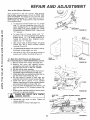
13, Level Mower Housing
Adjust the mower while tractor is parked on level ground
or driveway,
Make sqre tire pressures are 14 PS! in front;
t0 PS! in rear
41
Side
_;
O _
N_ "
FIGURE 43
23
to Side Mower Adjustment
a_ Move attachment
to full "UP" position
b Use a ruler to make sure bottom
of curl at rear of
mower deck are the same height from the ground
on each side (Fig 45),
c ffadjustment
is required, snap out access cover
on L H, side of tractor above footrest
(Fig 43),
d To raise left side of mower, loosen nut "'B'" and
screw nut "'A'" down on adjustment
rod
e. Adjust
until both rear mower
flanges
are the
same height
above the ground.
Tighten
nuts
"A'" and "B'" securely,
f
Snap access cover in place.
REPAIR AND ADJUSTMENT
Front to Rear Mower
Adjustment
Move attachment
to full "'UP" position
After leveling
side to side, measure
bottom
of curl at FRONT AND
REAR OF MOWER
The bottom of curl at the R H, front
flanges should measure
3/4"" lower than at the R H
REAR flange (Fig 45) If adjustment
is required
follow
the pr ocedure below
NUT
another free manual from www.searstractormanuals.com
a • To raise front of mower loosen nuts "D'.
Screw
nuts "C'" up onto suspension
arms (Fig, 44)_
NOTE: SCREW NUTS "C" ON BOTH SUSPENSION ARMS THE SAME NUMBER OF TURNS
SO MOWER WILL REMAIN
"D"
securely,
LEVEL
Tighten
NUT
c,
With mower
deck at desired
wheels
(Fig, 46) to lowest
touching
the ground,
d,
Useattachment
liftswitchto
proximate
cutting
height
e,
Use clevis pin (Fig, 46) to set gauge wheels
lowest
point without
touching
the gro_md,
44
BOTTOM
{FRONT FLANGESI
height, set gauge
position
without
set mower
you need,
to
FIGURE
_.
at the apat
14, Blade Drive Belt Removal and Replacement
BELT ROUTING DECAL UNDER MOWER DECK COVER°
a, Remove mower from tractor
(see page 23),
b. Remove
top
cover
self
tapping
screws,
lock washers
and nuts from idler atrn bolt.
c, Roll belt over the top of the R,.H. mandrel
d. Pull belt off all other mandrels,
e° Remove any dirt and grass which may have accumulated
around mandrels
and idler arm°
f o Check deck idler arm assembly and flat idler to
see that they rotate freely (Fig,. 47)_
go Be sure spring is hooked
in deck idler arm
assembly and on bolt in mower housing (Fig,,47),.
h. Install
new belt in groove
of L.H, mandrel
sheave, lower groove of center mandrel sheave
and around flat idler as shown (Fig_ 47).
i. From a position at discharge end of mower, roll
belt into groove of R H, mandrel sheave
(Fig,,
47).
j o Rotate center mandrel sheave by hand to make
sure belt is in grooves properly°
k,. Reassemble
top cover
screws
securely,,
Iv Install mower to tractor
FRONT
PARALLEL
LINK
ASSEMBLY
nuts
b_ To lower
f[ont
of mower
loosen
nuts "C"
Screw nuts "'D" down suspension arms NOTE:
SCREW NUTS "D"
THE SAME NUMBER
OF
TURNS
SO MOWER
WILL REMAIN
LEVEL
Tighten nuts "C"
securely,,
MANDREL
SHEAVES,
BLADES
WILL
ROTATE
o
D
WITH
deck,
(see page
FIGURE
RETAINER
SPRING
J
GAUGE _
CLEVIS
WHEEL
FLANGE
/
PiN
FIG URE 46
iDLER
NUT
CENTER
Tighten
45
ARM
CENTRAL MANDREL
SHEAVE
all
10),,
24
FIGURE47
AND
REPAIR
HEX HEAD HEAT --'-'_4 I
TREATED BOLT
_!_
GRADE 5
_
A.
Fuel System
NOTE: GASOLINE
STORAGE
STABILIZER
(SUCH AS
STA-BIL) MUST BE ADDED TO GASOLINE WHEN STORING UNiT
SUCH AN ADDITIVE
WILL MINIMIZE
FUEL
GUM
DEPOSITS
PREVENTING
A CLOGGED
FUEL
SYSTEM.
FOLLOW
DIRECTIONS
ON
STA-BIL
CONTAINER.
Run engine 10 minutes after adding STA-BIL to gasoline
to allow additive
to reach carburetor
FIGURE 49
another free manual from www.searstractormanuals.com
16. Blade Replacement
It is not necessary
to remove mower
from tractor
for
blade replacement.
Moving
adjustment
lift lever to up
(Rear) position
will permit access to blades
a•
b.
c
d
It is rmportant
to prevent
gum deposits from forming
in essential
fuel
system
parts such as the carburetor,
fuel filter,
fuel hose,
or tank
during
storage
Also. experience
indicates
that alcehel
blended
fuels
(called gasohel
or using ethanol
or methanol)
can attract
moisture
which
leads
to seraration
and formation
of acids during
storage
A_idi_ gas can damage
the fuet system
of an engine
while in storage
To avoid engine problems
the fuel system should
be emptied
before
Storage of 30 days or longer
Remove the hex head bolt, lockwasher
and flat
washer (Fig 49)
Remove and discard old blade
Clean top and bottom of mower
housing.
InstallnewbladewithSHARPEDGEDOWNand
secure with flat washer, Iockwasher
and hex
head bolt. TIGHTEN SECURELY,
ALWAYS
USE GRADE
5 HEAT
Be
Engine Oil
Drain (with engine warm) and replace with clean
engine oil, (See chart page 16)
C
Cylinders
1 Remove spark plugs
2
Pour one ounce of oil through spark plug holes
into cylinders
3.
Turn ignition key to "START"
position for a few
seconds
to distribute
oil,
4
Replace with new spark plugs
D,
Battery
1 Prior to storage,
clean terminals
and top of
battery,
2. After a period of time in storage,
battery may
require recharging
E o General Cleaning
Clean engine, battery,
seat, finish, etc. of all foreign
matter
F,
Store in a Clean Dry Area
TREATED
BOLTS IN BLADES OCCASIONALLY
TO
BOLTS
TO ATTACH
BLADES°
CHECK
MAKE SURE BOLTS ARE TIGHT. TORQUE
BOLTS 30 _ 35 FT° LBS.
G
A GRADE 5 HEAT TREATED BOLT
CAN BE IDENTIFIED BY THREE
LINES ON THE BOLT HEAD AS
SHOWN ON LEFT,
17_ Storage
Remove mower
from tractor for winter storage,
When
mower is to be stored 'for a period of time, clean it
thoroughly,
remove all dirt, grease, leaves, etco Store in
a clean dry area,
TROUBLESHOOTING
POSSIBLE CAUSE
WILL
NOT
TURN
ADJUSTMENT
CAUSE/REMEDY
(SEE INDEX)
Push
Clutch/Brake
Pedal
Move
Attachment
Clutch
into
Brake
Switch
to
Position
"Disengaged
Position
Charge
Battery
Replace
Ignition
Switch
Engage
Interlock
Switch
Replace
Interlock
Switch
Replace Solenoid
OVER
Replace Fuse
Check All Wire Connections
Fill
Tank
with
Gasoline
Check
Fuet Line and
(clean if necessary)
Replace Fuel
Check fuse for fault and replace
WILL
NOT
START
Recharge
or replace
Check Wiring
Carburetor
Filter
Battery
Replace Spark Plugs and adjust gap
Char qe or ReDface
ENGINE
HARD
CLICKS
BUT WON'T
START
Battery
Checkor Repfoce 5totter
Place Throttle
Control
in "FAST" position
and run starter several times to clear out gas
Remove and clean Fuel Tank and fines Replace Fuel
Remove Air Filter and clean
Replace
TO START
Spark
Plugs
and
adjust
gap
Replace Battery
Check
the wiring
and
Spark
Plugs
Drain Fuel Tank and Carburetor, use fresh fuel and
replace Spark Plugs
Make necessary
adjustments to Carburetor
Major Engine Overhaul Check Valve L_sh
25
Filter
"_
TROUBLESHOOTING
l
1
POSSIBLE CAUSE
ENGINE
MISSES
OR LACKS
CAUSE!REMEDY
(SEE INDEX)
Shift to a lower gear or reduce load
Remove and clean Tank_ replace Fuef Filter
Remove and clean Air Cleaner
Make necessary carburetor adjustments
Clean Air Screen
POWER
another free manual from www.searstractormanuals.com
Replace Spark Plugs
Add or change oil
Check Spark Plugs and check for any loose wires
Major Engine overhaul Check Valve L_sh
Drain Gas Tank and Carburetor and refill
Clean
ENGINE
Air
Screen
Add or change
oil
Clean Engine Cooling
Fins
Remove
and clean Muffler
or replace
Remove
and clean Air Filter
OVERHEATS
Use
fresh
fuel
and adjust
Carburetor
Check Fuse. Switch and Wire Connections
Replace Headlight Bulbs
NO LIGHTS
"Check Oil:
INDICATOR
LIGHTS
Check Oil Level
Check Oil Pump
Oil could be too light or diluted
'Battery Discharging":
Move throttle control to
fast positon.
"Depress Foot Pedal
Push clutch/brake
pedal
into brake position
"Disengage Attachment:
Move attachment clutch
switch to "Disengaged" position
LIT
Check air pressure in tires
Check front to real and side to side mower adjustment
Use a slower ground speed
Replace mower blades
Reinstall mower blades with top of blades up
Re-adjust
mower drive belt
Clean underside
of mower deck
UNSATISFACTORY
MOWER PERFORMANCE
UNEVEN DISTRIBUTION
OF CLIPPINGS
Sharpen
MOWER
BLADES
EXCESSIVE
Replace Bent or Unbalanced Blade
Replace Mandrel, Straighten Deck or replace
VIBRATION
WiND ROWING STRIPPING
OF GRASS CLIPPINGS
UNEVEN
Install new Mower Drive Belt
Reinstall Mower Drive Belt
Replace Attachment
Clutch Switch
Replace Frozen Mandrel
Replace Frozen Pulley
WILL NOT ROTATE
MOWER
blades
Let grass dry out
Clean underside of Mower
Level Mower
Replace Blades
OR DROPPING
Deck
Level Mower
Adjust Guage Wheels
Replace Blades
CUT OR SCALPING
Check for Fuse fault and replace
Replace Battery
Replace Regulator
Replace Alternator
WON'T CHARGE
OPERATOR PRESENCE SYSTEM WILL NOT SHUT
DOWN ENGINE WHEN OPERATOR LEAVES SEAT
Engage Attachment
Clutch
Check All Wire Connections
NOTE: THIS TRACTOR tS EQUIPPED WITH AN OPERATOR
PRESENCE SENSING SYSTEM.
ANY ATTEMPT
BY THE
OPERATOR TO LEAVE THE SEAT WITH THE ENGINE RUNNING AND THE ATTACHMENT CLUTCH ENGAGED WILL SHUT
DOWN THE ENGINE,
Check
Check
Check
26
Seat Switch
Operator
Presence
PTO Switch
Relay