1
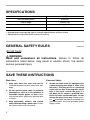
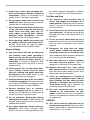
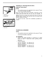
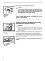
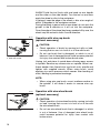
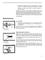
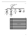
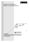
Angle Sander
MODEL 9060DBL
001015
DOUBLE
INSULATION
I N S T R U C T I O N
M A N U A L
WARNING:
For your personal safety, READ and UNDERSTAND before using.
SAVE THESE INSTRUCTIONS FOR FUTURE REFERENCE.
SPECIFICATIONS
Model
9060DBL
No load speed (RPM)
6,000/min
Overall length
458 mm (18”)
Net weight
4.2 kg (9.3 lbs)
Spindle thread
5/8”
• Manufacturer reserves the right to change specifications without notice.
• Specifications may differ from country to country.
GENERAL SAFETY RULES
USA002-2
(For All Tools)
WARNING:
Read and understand all instructions. Failure to follow all
instructions listed below, may result in electric shock, fire and/or
serious personal injury.
SAVE THESE INSTRUCTIONS
Work Area
Electrical Safety
1. Keep your work area clean and well lit.
Cluttered benches and dark areas invite accidents.
4. Double insulated tools are equipped with
a polarized plug (one blade is wider than
the other.) This plug will fit in a polarized
outlet only one way. If the plug does not fit
fully in the outlet, reverse the plug. If it
still does not fit, contact a qualified electrician to install a polarized outlet. Do not
change the plug in any way. Double insula-
2. Do not operate power tools in explosive
atmospheres, such as in the presence of
flammable liquids, gases, or dust. Power
tools create sparks which may ignite the dust
or fumes.
3. Keep bystanders, children, and visitors
away while operating a power tool. Distractions can cause you to lose control.
2
tion
eliminates the need for the three wire
grounded power cord and grounded power
supply system.
5. Avoid body contact with grounded surfaces such as pipes, radiators, ranges and
refrigerators. There is an increased risk of
electric shock if your body is grounded.
6. Do not expose power tools to rain or wet
conditions. Water entering a power tool will
increase the risk of electric shock.
7. Do not abuse the cord. Never use the cord
to carry the tools or pull the plug from an
outlet. Keep cord away from heat, oil,
sharp edges or moving parts. Replace
damaged cords immediately. Damaged
cords increase the risk of electric shock.
8. When operating a power tool outside, use
an outdoor extension cord marked “W-A”
or “W”. These cords are rated for outdoor
use and reduce the risk of electric shock.
Personal Safety
9. Stay alert, watch what you are doing and
use common sense when operating a
power tool. Do not use tool while tired or
under the influence of drugs, alcohol, or
medication. A moment of inattention while
operating power tools may result in serious
personal injury.
10. Dress properly. Do not wear loose clothing or jewelry. Contain long hair. Keep
your hair, clothing, and gloves away from
moving parts. Loose clothes, jewelry, or long
hair can be caught in moving parts.
11. Avoid accidental starting. Be sure switch
is off before plugging in. Carrying tools with
your finger on the switch or plugging in tools
that have the switch on invites accidents.
12. Remove adjusting keys or wrenches
before turning the tool on. A wrench or a
key that is left attached to a rotating part of
the tool may result in personal injury.
13. Do not overreach. Keep proper footing
and balance at all times. Proper footing and
balance enables better control of the tool in
unexpected situations.
14. Use safety equipment. Always wear eye
protection. Dust mask, non-skid safety
shoes, hard hat, or hearing protection must
be used for appropriate conditions. Ordinary
eye or sun glasses are NOT eye protection.
Tool Use and Care
15. Use clamps or other practical way to
secure and support the workpiece to a
stable platform. Holding the work by hand or
against your body is unstable and may lead
to loss of control.
16. Do not force tool. Use the correct tool for
your application. The correct tool will do the
job better and safer at the rate for which it is
designed.
17. Do not use tool if switch does not turn it
on or off. Any tool that cannot be controlled
with the switch is dangerous and must be
repaired.
18. Disconnect the plug from the power
source before making any adjustments,
changing accessories, or storing the tool.
Such preventive safety measures reduce the
risk of starting the tool accidentally.
19. Store idle tools out of reach of children
and other untrained persons. Tools are
dangerous in the hands of untrained users.
20. Maintain tools with care. Keep cutting
tools sharp and clean. Properly maintained
tools with sharp cutting edges are less likely
to bind and are easier to control.
21. Check for misalignment or binding of
moving parts, breakage of parts, and any
other condition that may affect the tools
operation. If damaged, have the tool serviced before using. Many accidents are
caused by poorly maintained tools.
22. Use only accessories that are recommended by the manufacturer for your
model. Accessories that may be suitable for
one tool, may become hazardous when used
on another tool.
SERVICE
23. Tool service must be performed only by
qualified repair personnel. Service or maintenance performed by unqualified personnel
could result in a risk of injury.
3
24. When servicing a tool, use only identical
replacement parts. Follow instructions in
the Maintenance section of this manual.
Use of unauthorized parts or failure to follow
Maintenance instructions may create a risk of
electric shock or injury.
USE PROPER EXTENSION CORD: Make sure your extension cord is in good condition.
When using an extension cord, be sure to use one heavy enough to carry the current your
product will draw. An undersized cord will cause a drop in line voltage resulting in loss of
power and overheating. Table 1 shows the correct size to use depending on cord length and
nameplate ampere rating. If in doubt, use the next heavier gage. The smaller the gage number, the heavier the cord.
Table 1: Minimum gage for cord
Volts
120 V
Ampere Rating
More Than
Not More Than
0
6
10
12
6
10
12
16
25 ft.
Total length of cord in feet
50 ft.
100 ft.
150 ft.
AWG
18
18
16
14
16
16
16
12
SPECIFIC SAFETY RULES
16
14
14
12
14
12
Not Recommended
USB038-5
DO NOT let comfort or familiarity with product (gained from
repeated use) replace strict adherence to sander safety rules. If
you use this tool unsafely or incorrectly, you can suffer serious
personal injury.
1. Accessories must be rated for at least the
speed recommended on the tool warning
label. Wheels and other accessories running
over rated speed can fly apart and cause
injury.
2. Hold tool by insulated gripping surfaces
when performing an operation where the
cutting tool may contact hidden wiring or
its own cord. Contact with a “live” wire will
make exposed metal parts of the tool “live”
and shock the operator.
3. Always use safety glasses or goggles.
Ordinary eye or sun glasses are NOT
safety glasses.
4
4. Use only flanges specified for this tool.
5. NEVER use tool with wood cutting blades
or other sawblades. Such blades when
used on a sander frequently kick and
cause loss of control leading to personal
injury.
6. Hold the tool firmly.
7. Keep hands away from rotating parts.
8. Be careful not to damage the spindle, the
flange (especially the installing surface)
or the lock nut. Damage to these parts
could result in wheel breakage.
9. Make sure the abrasive disc or the wheel
is not contacting the workpiece before the
switch is turned on.
10. Watch out for flying sparks. Hold the tool
so that sparks fly away from you and other
persons or flammable materials.
11. Do not leave the tool running. Operate the
tool only when hand-held.
12. Do not touch the workpiece immediately
after operation; it may be extremely hot
and could burn your skin.
13. Ventilate your work area adequately when
you perform sanding operations.
14. ALWAYS wear proper apparel including
long sleeve shirts, leather gloves and
shop aprons to protect skin from contact
with hot grindings.
15. Use of this tool to grind or sand some
products, paints and wood could expose
user to dust containing hazardous substances. Use appropriate respiratory protection.
IF USED AS A GRINDER
16. Always use proper guard with grinding
wheel. A guard protects operator from broken wheel fragments.
17. When using depressed center grinding
wheels, be sure to use only fiberglassreinforced wheels.
18. Check the wheel carefully for cracks or
damage
before
operation.
Replace
cracked or damaged wheel immediately.
Run the tool (with guard) at no load for
about a minute, holding tool away from
others. If wheel is flawed, it will likely separate during this test.
19. Before using the tool on an actual workpiece, let it run for a while. Watch for
vibration or wobbling that could indicate
poor installation or a poorly balanced
wheel.
20. Use the specified surface of the wheel to
perform the grinding.
SAVE THESE INSTRUCTIONS
WARNING:
MISUSE or failure to follow the safety rules stated in this
instruction manual may cause serious personal injury.
SYMBOLS
USD291-2
The followings show the symbols used for tool.
V ....................... volts
A ....................... amperes
.............. alternating or direct current
n ....................no load speed
˚
....................Class II Construction
.../min................revolutions or reciprocation per
minute
5
FUNCTIONAL
DESCRIPTION
•
001026
CAUTION:
Always be sure that the tool is switched off and
unplugged before adjusting or checking function on the
tool.
Shaft lock
1
•
CAUTION:
Never actuate the shaft lock when the spindle is moving.
The tool may be damaged.
Press the shaft lock to prevent spindle rotation when installing or removing accessories.
1. Shaft lock
001041
Switch action
•
1
•
2
1. Switch trigger
2. Lock lever
CAUTION:
Before plugging in the tool, always check to see that the
switch trigger actuates properly and returns to the “OFF”
position when released.
Switch can be locked in “ON” position for ease of
operator comfort during extended use. Apply caution
when locking tool in “ON” position and maintain firm
grasp on tool.
To start the tool, simply pull the switch trigger. Release the
switch trigger to stop. For continuous operation, pull the
switch trigger and then push in the lock lever. To stop the tool
from the locked position, pull the switch trigger fully, then
release it.
ASSEMBLY
•
001057
CAUTION:
Always be sure that the tool is switched off and
unplugged before carrying out any work on the tool.
Installing side grip (handle)
•
CAUTION:
Always be sure that the side grip is installed securely
before operation.
Screw the side grip securely on the position of the tool as
shown in the figure.
6
001112
1
Installing or removing abrasive disc
(optional accessory)
2
3
NOTE:
•
Mount the rubber pad onto the spindle. Fit the disc on the
rubber pad and screw the lock nut onto the spindle. To
tighten the lock nut, press the shaft lock firmly so that the
spindle cannot revolve, then use the lock nut wrench and
securely tighten clockwise.
1. Lock nut
2. Abrasive disc
3. Rubber pad
001089
1
Use sander accessories specified in this manual. These
must be purchased separately.
To remove the disc, follow the installation procedure in
reverse.
2
1. Lock nut wrench
2. Shaft lock
IF USED AS A GRINDER
NOTE:
•
•
•
Use grinder accessories specified in this manual. These
must be purchased by separate.
WARNING:
Always use guard assembly or accessory kit, noted
below, for type 27 depressed center grinding wheel/
Multi-disc.
Guard assembly
Part No. 192578-8 ... For 180 mm (7”)
Part No. 192588-5 ... For 230 mm (9”)
Guard accessory kit
Part No. 192606-9 ... For 180 mm (7”)
Part No. 192607-7 ... For 230 mm (9”)
7
001064
Installing or removing wheel guard
1
•
3
2
CAUTION:
When using a depressed center grinding wheel/Multidisc, flex wheel or wire wheel brush, the wheel guard
must be fitted on the tool so that the closed side of the
guard always points toward the operator.
Mount the wheel guard with the protrusion on the wheel
guard band aligned with the notch on the bearing box. Then
rotate the wheel guard around 180 degrees. Be sure to
tighten the screw securely.
1. Wheel guard
2. Bearing box
3. Screw
To remove wheel guard, follow the installation procedure in
reverse.
001076
1
Installing or removing depressed center grinding
wheel/Multi-disc (optional accessory)
2
3
•
1. Lock nut
2. Depressed center grinding wheel/
Multi-disc
3. Inner flange
001089
1
WARNING:
Always use optional guard when depressed center
grinding wheel/Multi-disc is on tool. Wheel can shatter
during use and guard helps to reduce chances of
personal injury.
Mount the inner flange onto the spindle. Fit the wheel/disc on
the inner flange and screw the lock nut onto the spindle.
To tighten the lock nut, press the shaft lock firmly so that the
spindle cannot revolve, then use the lock nut wrench and
securely tighten clockwise.
To remove the wheel, follow the installation procedure in
reverse.
2
1. Lock nut wrench
2. Shaft lock
8
001101
1
2
Installing or removing flex wheel
(optional accessory)
3
4
•
1.
2.
3.
4.
Lock nut
Flex wheel
Plastic pad
Inner flange
WARNING:
Always use specific guard when depressed center
grinding wheel/Multi-disc is on tool. Wheel can shatter
during use and guard helps to reduce chances of
personal injury.
Follow instructions for depressed center grinding wheel/
Multi-disc but also use plastic pad over wheel. See order of
assembly on accessories page in this manual.
001089
1
2
1. Lock nut wrench
2. Shaft lock
OPERATION
001130
•
15˚
WARNING:
It should never be necessary to force the tool. The
weight of the tool applies adequate pressure. Forcing
and excessive pressure could cause dangerous wheel
breakage.
•
ALWAYS replace wheel if tool is dropped while grinding.
•
NEVER bang or hit grinding disc or wheel onto work.
•
Avoid bouncing and snagging the wheel, especially
when working corners, sharp edges etc. This can cause
loss of control and kickback.
•
NEVER use tool with wood cutting blades and other
sawblades. Such blades when used on a grinder
frequently kick and cause loss of control leading to
personal injury.
•
CAUTION:
After operation, always switch off the tool and wait until
the wheel has come to a complete stop before putting
the tool down.
9
ALWAYS hold the tool firmly with one hand on rear handle
and the other on the side handle. Turn the tool on and then
apply the wheel or disc to the workpiece.
In general, keep the edge of the wheel or disc at an angle of
about 15 degrees to the workpiece surface.
During the break-in period with a new wheel, do not work the
grinder in the B direction or it will cut into the workpiece.
Once the edge of the wheel has been rounded off by use, the
wheel may be worked in both A and B direction.
001141
Operation with wire cup brush
(optional accessory)
1
2
•
•
1. Wire cup brush
2. Urethane washer
CAUTION:
Check operation of brush by running tool with no load,
insuring that no one is in front of or in line with brush.
Do not use brush that is damaged, or which is out of
balance. Use of damaged brush could increase potential
for injury from contact with broken brush wires.
Unplug tool and place it upside down allowing easy access
to spindle. Remove any accessories on spindle. Mount urethane washer then thread wire cup brush onto spindle and
tighten with supplied wrench. When using brush, avoid
applying too much pressure which causes over bending of
wires, leading to premature breakage.
NOTE:
•
001234
1
Operation with wire wheel brush
(optional accessory)
•
1. Wire wheel brush
10
When using wire cup brush, mount urethane washer to
the spindle. It will make it easier to remove wire cup
brush.
•
CAUTION:
Check operation of wire wheel brush by running tool with
no load, insuring that no one is in front of or in line with
the wire wheel brush.
Do not use wire wheel brush that is damaged, or which
is out of balance. Use of damaged wire wheel brush
could increase potential for injury from contact with
broken wires.
•
ALWAYS use guard with wire wheel brushes, assuring
diameter of wheel fits inside guard. Wheel can shatter
during use and guard helps to reduce chances of
personal injury.
Unplug tool and place it upside down allowing easy access
to spindle. Remove any accessories on spindle. Thread wire
wheel brush onto spindle and tighten with the wrenches.
When using wire wheel brush, avoid applying too much pressure which causes over bending of wires, leading to premature breakage.
MAINTENANCE
001170
CAUTION:
• Always be sure that the tool is switched off and
unplugged before attempting to perform inspection or
maintenance.
1
The tool and its air vents have to be kept clean. Regularly
clean the tool’s air vents or whenever the vents start to
become obstructed.
2
1. Exhaust vent
2. Inhalation vent
001146
Replacing carbon brushes
When the resin insulating tip inside the carbon brush is
exposed to contact the commutator, it will automatically shut
off the motor. When this occurs, both carbon brushes should
be replaced. Keep the carbon brushes clean and free to slip
in the holders.
2
1
3
Use a screwdriver to remove the brush holder caps. Take out
the worn carbon brushes, insert the new ones and secure
the brush holder caps.
1. Commutator
2. Insulating tip
3. Carbon brush
001154
To maintain product SAFETY and RELIABILITY, repairs, any
other maintenance or adjustment should be performed by
Makita Authorized or Factory Service Centers, always using
Makita replacement parts.
1
2
1. Brush holder cap
2. Screwdriver
11
ACCESSORIES
•
•
CAUTION:
These accessories or attachments are recommended for
use with your Makita tool specified in this manual. The
use of any other accessories or attachments might
present a risk of injury to persons. Only use accessory or
attachment for its stated purpose.
If you decide to use your Makita sander with approved
accessories which you purchase from your Makita
distributor or factory service center, be sure to obtain
and use all necessary fasteners and guards as
recommended in this manual. Your failure to do so could
result in personal injury to you and others.
If you need any assistance for more details regarding these
accessories, ask your local Makita service center.
12
001188
1
2
2
8
2
12
3
3
9
11
13
4
6
10
5
7
5
C00169
9060DBL
1
Grip 36
2
Wheel guard
3
Inner flange 89
4
Depressed center grinding wheel/Multi-disc
5
Lock nut 5/8-40
6
Plastic pad
7
Flex wheel
8
Rubber pad 170
9
Abrasive disc
10
Sanding lock nut 5/8-48
11
Wire wheel brush
12
Urethane washer 14
13
Wire cup brush
-
Lock nut wrench 28
-
Accessory kit 7” or 9”
13
Memo
14
Memo
15
MAKITA LIMITED ONE YEAR WARRANTY
Warranty Policy
Every Makita tool is thoroughly inspected and tested before leaving the factory. It is warranted to be free of defects from
workmanship and materials for the period of ONE YEAR from the date of original purchase. Should any trouble develop during
this one year period, return the COMPLETE tool, freight prepaid, to one of Makita’s Factory or Authorized Service Centres.
If inspection shows the trouble is caused by defective workmanship or material, Makita will repair (or at our option, replace)
without charge.
This Warranty does not apply:
• where normal maintenance is required,
• repairs have been made or attempted by others,
• the tool has been abused, misused or improperly maintained,
• alterations have been made to the tool.
IN NO EVENT SHALL MAKITA BE LIABLE FOR ANY INDIRECT, INCIDENTAL OR CONSEQUENTIAL DAMAGES FROM
THE SALE OR USE OF THE PRODUCT. THIS DISCLAIMER APPLIES BOTH DURING AND AFTER THE TERM OF THIS
WARRANTY.
“The Makita Warranty is the only and the entire written warranty given by Makita for the Makita tools. No dealer or his agent
or employee is authorized to extend or enlarge upon this warranty by any verbal or written statement or advertisement.”
MAKITA DISCLAIMS LIABILITY FOR ANY IMPLIED WARRANTIES INCLUDING IMPLIED WARRANTIES OF
“MERCHANTABILITY” AND FITNESS FOR A SPECIFIC PURPOSE,” AFTER THE ONE YEAR TERM OF THIS WARRANTY.
“This Warranty gives you specific rights. The provisions contained in this warranty are not intended to limit, modify, take away
from, disclaim or exclude any warranties set forth in any provincial legislation. To the extent required by law, the provisions in
any provincial or federal legislation with respect to warranties take precedence over the provisions in this warranty.”
Makita Canada Inc.
1950 Forbes Street, Whitby, Ontario L1N 7B7
884594-239