1
Operator's
Manual
Weedwacker
Gas Trimmer
20cc/1.2 cu.in. 2-Cycle
15 Inch Cutting Path / 0.080 In. Line
Model No.
358.791620
•
Safety
•
•
•
Assembly
Operation
Maintenance
•
Parts List
•
Eapar_ol, p. 19
WARNING:
Read and follow all Safety Rules and Operating
Instructions
before first use of this product.
For answers
Call
7 am-7
to your
questions or about
this pm,
product:
pm,
Mon.-Sat.,
10 am-7
Sun.
1-800-235-5878
Sears, Roebuck
545177386
_Hoo,o ,isted are Central
and Co., Hoffman
Rev. 2 3/26/08
BRW
Estates,
Time)
IL 60179 U.S.A.
Warranty
Statement
2
Identification of Safety Symbols
Safety Rules
Assembiy
Operation
Maintenance
Service & Adjustments
ONE YEAR FULL WARRANTY
2
4
6
7
tl
12
Storage
13
Troubteshooting
Chart
Emissions Statement
14
15
Parts List
Spanish
Parts and Ordering
17
19
Back
ON GAS WEEDWACKER
When used and maintained according to the operator's manual, ff this product fails due
to a defect in material or workmanship within one year from the date of purchase, return
it to any Sears store or Sears Service Center in the United States for free repair (or replacement if repair proves impossible).
This warranty excludes cutting line, spark plug and air fiiter, which are expendabie
parts that can wear out from normal use in less than one year.
This warranty applies for only 90 days from purchase date if this product is ever used
for commercial or rentat purposes.
This warranty gives you specific legal rights, and you may also have other rights
which vary from state to state.
Sears, Roebuck and Co., Hoffman Estates, IL 60179
@
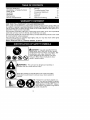
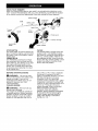
_DANGER:
Use only specified trimmer
head, spoot, and 0.080 inch (2 mm) recommended trimmer line. Never use blades, flailing devices, wire, rope, string, etc. This
unit is designed for line trimmer use only.
Failure to foIIow these instructions may
result in serious injury.
®®®
1
I_
I
improper use can cause serious injury.
I'_WARNING:
This unit can be dangerous!
CareIess or
Read the operator's
manual
before use. Failure to follow
instructions
coutd result in serious
injury. Save operator's
manual
_]
lently, You can be blinded or injured,
Always wear hearing protection and
safety glasses marked Z87. Always
Trimmer
line tong
can throw
viowear
heavy,
pants, objects
long sleeve
boots and gloves,
Hazard
zoneforthrown
objects.
• Trimmer
linethrows
objects
violently.
• Youandothers
canbeblinded/injured.
• Keep
children,
bystanders,
andanimals
50feet(t5meters)
away.
• _'_
| _
__. _
_W
0
I Do not wear jeweIry, loose clothing,
v,j I or clothing with loosing hanging
_
I straps,
Secure ties,
hair tassels,
above shoulder
etc. Theylength.
can
/ be caught in moving parts.
1
1
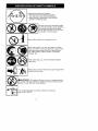
I Never allow children to operate this unit.
Store unit indoors in a high, dry place out of the
reach of children. Store unit and fuet in area where
fuel vapors cannot reach sparks or open flames
from water heaters, electric motors or switches,
furnaces, etc,
When servicing
ment parts.
unit, use onty identical replace-
Always stop unit and disconnect
cleaning or servicing.
spark plug before
1o--_ru
sweat
ReNulrNitGn:eFa
ire _aaZmar
dorNse;se_sm(iXciPOcU
r4gOrsStOrke4aSo°p
line
Jflames,
or work that can cause sparks).
ratio of 40:1 (2.5%),
Use unleaded gasoline and two-stroke
oil mixed at a
• Stay atert. Do not operate this unit
when you are tired, ill, upset or under
the influence of alcohot, drugs, or
medication. Watch what you are doing; use common sense.
Wear hearing protection.
• Never start or run inside a closed
room or building. Breathing exhaust
fumes can kill.
• Keep handles free of oil and fuel.
UNIT / MAINTENANCE
SAFETY
dI_IWARNING:
When
using
gardening
appliances,
basic
safety
precautions
must
always
befollowed
to
reduce
theriskoffireandserious
injury.
Read
andfollow
attinstructions.•
This power unit can be dangerous!
Operator is responsible for foIIowing
instructions and warnings on unit and in
manual. Read entire operator's manual
before using unit! Be thoroughly familiar
with the controls and the proper use of
the unit. Restrict the use of this unit to
persons who have read, understand,
and wilI follow the instructions and
warnings on the unit and in the manual.
Never allow children to operate this unit.
OPERATOR'S
MANUAL
_WARNING:
Stop unitand disconnect the spark plug before performing maintenance (except carburetor adjustments).
• Look for and replace damaged or
loose parts before each use. Look for
and repair fuel leaks before use, Keep
in good working condition.
• Replace trimmer head parts that are
chipped, cracked, broken, or damaged in any other way before using
the unit.
• Maintain unit according to recommended procedures. Keep cutting line
at proper length.
• Use only 0.080 inch (2 mm) diameter
line, Never use wire, rope, string, etc.
• Install required shield properly before
using the unit. Use onty specified trimmer head; make sure it is properly
installed and securely fastened.
• Make sure unit is assembled correctly
as shown in this manual.
• Make carburetor adjustments with
lower end supported to prevent line
from contacting any object.
• Keep others away when making carburetor adjustments.
• Use onty recommended accessories
and replacement parts.
• Have atl maintenance and service not
explained in this manual performed by
a Sears Service Center.
SAFETYINFORMATION
ONTHE UNET
A
DANGER:
Never use blades or
flailing devices. This unit is designed
for line trimmer use only. Use of any
other accessories or attachments will
increase the risk of injury.
If situations occur which are not covered in this manual, use care and
good judgment. If you need assistance, contact your Sears Service
Center or calt 1-800-235-5878.
OPERATOR SAFETY
• Dress properly. Always wear safety
giasses or simitar eye protection when
operating, or performing maintenance,
on your unit (safety glasses are available). Eye protection should be
marked Z87.
• Always wear face or dust mask if operation is dusty.
• Always wear heavy, long pants, tong
sleeves, boots, and gloves. Wearing
safety teg guards is recommended.
• Always wear foot protection, Do not
go barefoot or wear sandals. Stay
clear of spinning line.
• Secure hair above shoulder tength.
Secure or remove loose clothing or
clothing with toosely hanging ties,
straps, tassels, etc. They can be
caught in moving parts.
• Being fully covered also hetps protect
you from debris and pieces of toxic
piants thrown by spinning line.
FUEL SAFETY
• Mix and pour fuel outdoors.
• Keep away from sparks or flames.
• Do not smoke or allow smoking near
fueI or the unit.
• Avoid spilling fueI or oit. Wipe up alI
fuel spills.
• Move at least 10 feet (3 meters) away
from fueling site before starting engine. Stop engine and allow it to cool
before removing fuel cap.
• Empty the fuel tank before storing or
transporting the unit. Use up fuel left
4
inthecarburetor
bystarting
theengineandletting
itrununtil_tstops.
• Store
unitandfuelinarea
where
fuel
vapors
cannot
reach
sparks
oropen
flames
fromwater
heaters,
electric
motors
orswitches,
furnaces,
etc.
• Always
store
gasoIine
inacontainer
approved
forflammable
liquids.
CUTTING
SAFETY
,_
WARNING:
Inspect
the area
be-
fore each use. Remove objects
(rocks, broken glass, nails, wire, etc.)
which can be thrown by or become
entangled in tine. Hard objects can
damage the trimmer head and be
thrown causing serious injury.
• Use only for trimming, scalping, mowing and sweeping. Do not use for edging, pruning or hedge trimming.
• Keep firm footing and balance. Do not
overreach.
• Keep all parts of your body away from
muffler and spinning line. Keep engine
below waist level A hot muff{er can
cause serious bums.
• Cut from your right to your left. Cutting
on left side of the shield will throw debris away from the operator.
• Use only in daylight or good artificial
light.
• Use only for jobs expIained in this
manual,
TRANSPORTING
AND STORAGE
• Stop the unit before carrying.
• Allow engine to cool; secure unit before storing or transporting in vehicle.
• Empty the fuel tank before storing or
transporting the unit. Use up fuet left
in the carburetor by starting the engine and tetting it run until it stops.
• Store unit and fuel in area where fuel
vapors cannot reach sparks or open
flames from water heaters, electric
motors or switches, furnaces, etc.
• Store unit so line timiter blade cannot
accidentally cause injury. The unit
can be hung by the tube.
• Store unit out of reach of children.
This unit is not equipped with an antivibration system and is intended for
occasional use only.
SAFETY NOTICE: Exposure to vibrations through prolonged use of gasoline powered hand tools could cause
blood vessel or nerve damage in the
fingers, hands, and joints of peopIe
prone to circulation disorders or abnormat swellings. Prolonged use in
cotd weather has been Iinked to blood
vessel damage in otherwise heatthy
peopte, tf symptoms occur such as
numbness, pain, loss of strength,
change in skin cotor or texture, or toss
of feeling in the fingers, hands, or
ioints, discontinue the use of this tool
and seek medical attention.
An anti-vibration
system does not
guarantee the avoidance of these
problems. Users who operate power
tools on a continual and regular basis
must monitor closely their physical
condition and the condition of this tooL
SPECIAL NOTICE: This unit is
equipped with a temperature limiting
muffler and spark arresting screen
which meets the requirements of California Codes 4442 and 4443. All U.S.
forest land and the states of California,
Idaho, Maine, Minnesota, New Jersey,
Oregon, and Washington require by
Iaw that many internal combustion engines be equipped with a spark arresting screen. Ifyou operate in a locale
where such regulations exist, you are
tegally responsible for maintaining the
operating condition of these parts.
Failure to do so is a violation of the
Iaw. For normal homeowner use, the
muffler and spark arresting screen will
not require any service. After 50 hours
of use, we recommend that your muffler be serviced or replaced by your
Sears Service Center.
CARTON
CONTENTS
Check
carton
contents
against
thefolIowing
tist.
Model 358.791620
• Trimmer
• Shield
• Container of Oil
Examine parts for damage. Do not
use damaged parts.
NOTE: If you need assistance or find
parts missing or damaged, call
1-800-235-5878.
It is normal for the fuel filter to rattle in
the empty fuel tank.
Finding fuel or oil residue on muffler is
normat due to carburetor adjustments
and testing done by the manufacturer.
ASSEMBLY
,I_WARNING:
Always stop unit
and disconnect spark plug before performing any assembly procedures.
_WARNING:
If received
as-
sembled,
repeat all steps to ensure
your unit is properly assembled and aIt
fasteners are secure.
ADJUSTING
THE HANDLE
_WARNING:
When adjusting the
assist handle, be sure it remains above
the safety label and betow the mark or
arrow on the shaft.
1. Loosen wing nut on handle.
2. Rotate the handle on the shaft to an
upright position; retighten wing nut.
ATTACHING
SHIELD
_WARNING:
The shield must be
properly installed. The shield provides
partial protection from the risk of thrown
objects to the operator and others and
is equipped with a tine limiter blade
which cuts excess line to the proper
length. The line limiter btade (on underside of shield) is sharp and can cut you.
For proper orientation of shield, see
KNOW YOUR TRIMMER iIlustration in
OPERATION section.
1.
2.
3.
4.
Remove wing nut from shield.
Insert bracket into slot as shown.
Pivot shield until bo_t passes
through hole in bracket.
Securely tighten wing nut onto boIt.
Slot
Shield
Bracket
PIVOT
Line Umiter
Blade
Wing
Nut
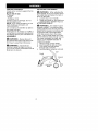
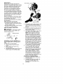
KNOW YOUR TRIMMER
READ THIS OPERATOR'S MANUAL AND SAFETY RULES BEFORE OPERATING YOUR
UNiT Compare the illustrations with your unit to famiIiarize yourself with the location
of the various controls and adjustments. Save this manual for future reference.
Muffler
Assist Handle
""_
Shaft
i
Shaft Mark
or Arrow
Safety Label
Spark
Trimmer
Head
Plug k_
Primer
Bulb
_%- Throttle
Trigger
STOP
ShieId
Fuel Mix FiII Cap
Line Umiter
Blade
Starter Handle
STOP SWITCH
The STOP switch is used to stop the engine. To stop the engine, push and hold
the switch in the STOP position until the
engine stops.
PRIMER BULB
The PRIMER BULB removes air from
the carburetor and fuel tines and fitls
them with fuel. This atiows you to start
the engine with fewer pulls on the
starter rope. Activate the primer bulb
by pressing it and aliowing it to return
to its original form.
CHOKE
The CHOKE helps to supply fuel to the
engine to aid in cold starting. Activate
the choke by moving the choke lever to
the FULL CHOKE position. After the engine attempts to start, move the choke
tever to the HALF CHOKE position. Once
engine has started, move the choke
tever to the RUN position.
BEFORE
ratio of 40:1. A 40:1 ratio is obtained
by mixing 3.2 ounces of oit with 1
galton of unleaded gasoline. Included
with this trimmer is a 3,2 ounce
container of oil. Pour the entire
contents of this container into 1 gallon
of gasoline to achieve the proper fuel
mixture. DO NOT USE automotive oii or
marine oil. These oils will cause
engine damage. When mixing fuel,
follow instructions printed on
container, Once oil is added to
gasoline, shake container momentarily
to assure that the fuel is thoroughly
mixed. Always read and follow the
safety rules relating to fuel before
fueling your unit.
STARTING
_IIWARNING:
ENGINE
Be sure to read
the fuel information in the safety rules
before you begin. If you do not
understand the safety rules, do not
attempt to fuet your unit. Call
1-800-235-5878.
FUELING ENGINE
_[k WARNING:
Remove fuel cap
slowly when refueling.
This engine is certified to operate on
unIeaded gasoline. Before operation,
gasotine must be mixed with a good
quaIity synthetic 2-cycte air-cooled
engine oil. Mix gasoline and oil at a
7
IMPORTANT
Primer Bulb
Experience
indicates
thatalcohol
blended
fuels(called
gasohol
orusing
ethanol
ormethanol)
canattract
moisturewhich
leads
toseparation
and
formation
ofacids
during
storage.
Acidic
gascandamage
thefuelsystemofanengine
whileinstorage.
\ Choke
Toavoid
engine
problems,
empty
the
Lever
fuelsystem
before
storage
for30days
orlonger.
Drain
thegastank,
startthe
engine
andletitrununtilthefuellines
andcarburetor
areempty.
Usefresh
fuetnextseason.
Never
useengine
orcarburetor
cleanerproducts
inthefueltankorpermanentdamage
mayoccur.
SeetheSTORAGE
section
foradditionalinformation,
HOW
TOSTOP
YOUR
UNIT
Starter Handle
• Tostoptheengine,
push
andhotd
theSTOP
switch
intheSTOP
position 5. Pult starter rope handle sharply until
untiltheengine
stops.
engine sounds as if it is trying to
• Ifengine
doesnotstop,
move
choke
start, but do not pull rope more than
totheFULL
CHOKE
position.
6 times.
HOW
TOSTART
YOUR
UNIT
6. As soon as engine sounds as if it is
trying to start, move choke lever to
_IJWARNING:
Avoid
anycontact
HALF CHOKE position,
withthemuffter.
Ahotmuffler
can
7. Pull starter rope sharply untit engine
cause
serious
burns,
runs, but no more than 6 pulls.
Starting
Position
STARTING A COLD ENGINE (or a
warm engine after running out of
fuel)
1. Set unit on a flat surface.
2. SlowIy press the primer bulb 6
times.
3, Move choke lever to the FULL
CHOKE position.
4. Squeeze the throttle tdgger futly and
hold through all remaining steps.
NOTE: If the engine doesn't start
after 6 pulls (at the HALF CHOKE
position), move the choke lever to
the FULL CHOKE position and press
the primer bulb 6 times. Squeeze
and hold the throttle trigger and pull
the starter rope 2 more times. Move
the choke lever to the HALF CHOKE
position and pull the starter rope until the engine runs, but no more than
6 pulls, tf the engine still doesn't
start, it is probably flooded, Proceed
to STARTING A FLOODED ENGINE.
8. Once the engine starts, allow it to
run 10 seconds, then move the
choke lever to the RUN position.
Allow the unit to run for 30 more seconds at RUN before releasing the
throttle trigger. NOTE: If engine
dies with the choke lever in the
RUN position, move the choke lever to the HALF CHOKE position
and pull the rope untit engine runs,
but no more than 6 pulls.
STARTING A WARM ENGINE
1. Move the choke lever to the HALF
CHOKE position.
2. Squeeze and hold the throttle trigger. Keep throttle trigger fully
squeezed until the engine runs
smoothly.
3, PulIstarter
rope
sharply
until
engine Do not run the engine at a higher
runs,
butnomore
than6pulls.
speed than necessary. The cutting
4, Allow
engine
torun15seconds, Iine wilt cut efficiently when the engine
thenmove
thechoke
lever
toRUN. is run at less than full throttle. At lower
speeds, there is tess engine noise and
NOTE:
tfengine
hasnotstar_ed,
pull
starter
rope5more
pulls,
tfengine
still vibration.
doesnotrun,itisprobably
flooded. The cutting line will last longer and will
less likely to "weld" onto the spool.
STARTING
AFLOODED
ENGINE be
Always release the throttle trigger and
Flooded
engines
canbestarted
by
allow the engine to return to idle
placing
thechoke
lever
intheRUN
speed when not cutting.
position;
then,pulltherope
toclear
theengine
ofexcess
fuel.Thiscould HOW TO STOP YOUR UNIT
require
pulling
thestarter
handle
many • Release the throttle trigger.
times
depending
onhowbadly
the
• Push and release the engine STOP
switch.
unitisflooded.
Iftheunitstilldoesn't
start,refertoTROUBLESHOOTING
TA- TRIMMER LINE ADVANCE
BLE
orcall1-800-235-5878.
The trimmer line wiIt advance approxiOPERATING
INSTRUCTIONS mately 2 inches (5 cm) each time the
bottom of the trimmer head is tapped
Tomaximize operating efficiency, do
not run the engine for longer than 1
minute at a time at full throttle.
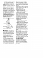
OPERATING POSITION
ALWAYS WEA_. I
_
Eye protection
Heavy shoes
Out from your right to your left
_IIWARNING:
Always wear eye
protection. Always use hearing protection. Never lean over the trimmer head.
Rocks or debris can ricochet or be
thrown into eyes and face and cause
blindness or other serious injury.
When operating unit, stand as shown
and check for the following:
• Wear eye protection and heavy
clothing.
• Hold trigger handle with right hand
and assist handle with left hand.
• Hold unit so that engine is below
waist level.
• Cut only from your right to your left to
ensure debris is thrown away from
you. Without bending over, keep line
near and parallel to the ground and
not crowded into material being cut.
on the ground with the engine running
at full throttle.
The most efficient line length is the
maximum length allowed by the line
timiter. Always keep the shield in place
when the tool is being operated.
To advance line:
• Operate the engine at full throttle.
• Hold the trimmer head parallel to
and above the grassy area.
• Tap the bottom of the trimmer head
lightly on the ground one time. Approximately 2 inches (5 cm) of line
will be advanced with each tap.
Always tap the trimmer head on a
grassy area. Tapping on surfaces such
as concrete or asphalt can cause excessive wear to the trimmer head.
If the line is worn down to 2 inches (5
cm) or less, more than one tap will be
required to obtain the most efficient line
length.
,_ WARNING:
Use only 0,080 inch
(2 mm) diameter round line. Other
sizes and shapes of line witt not advance properly and wilt result in improper cutting head function or can
cause serious injury. Do not use other
materials such as wire, string, rope,
etc. Wire can break off during cutting
and become a dangerous missile that
can cause serious injury.
CUTTING
METHODS
Use minimum speed and do not
crowd the line when cutting around
hard objects (rock, gravel, fence
posts, etc.), which can damage the
trimmer head, become entangled in
the line, or be thrown causing a serious hazard.
• Thetipofthelinedoes
thecutting.
Youwillachieve
thebestperformanceandminimum
_ine
wearbynot
crowding
thelineintothecutting
area,
Therightandwrong
waysare
shown
below.
TipoftheLine Line
Crowded
Into
Does
TheCutting
Work
Area
SCALPtNGThe sca_ping technique
removes unwanted vegetation down
to the ground. Hold the bottom of the
trimmer head about 3 inches (8 cm)
above the ground and at an angle. Atlow the tip of the line to strike the
ground around trees, posts, monuments, etc. This technique increases
line wear.
Scalping
" rN_
-'Right
Wrong _"
• Thelinewitleasily
remove
grass
andweeds
fromaround
waits,
fences,
treesandflower
beds,
butit
alsocancutthetender
barkoftrees
orshrubs
andscarfences.
Tohelp
avoid
damage
especially
todelicate
vegetation
ortreeswithtender
bark,
shorten
lineto4-5inches
(1O-t3
cm)anduseattess than full throttle.
• For trimming or scaIping, use less
than full throttle to increase line life
and decrease head wear, especially:
• During light duty cutting.
• Near objects around which the line
can wrap such as small posts,
trees or fence wire.
• For mowing or sweeping, use full
throttte for a good clean job.
TRIMMING -HoId the bottom of the
trimmer head about 3 inches (8 cm)
above the ground and at an angte. AItow onty the tip of the iine to make
contact with vegetation. Do not force
trimmer tine into work area.
Trimming
/
. •
_,
"
,
,
MOWING - Your trimmer is ideal for
mowing in places conventionaI lawn
mowers cannot reach, tn the mowing
position, keep the Iine parallel to the
ground. Avoid pressing the head into
the ground as this can scaIp the
ground and damage the tool.
SWEEPING - The fanning action of
the rotating Hne can be used for a
quick and easy ciean up. Keep the
Iine paraIlet to and above the surfaces
being swept and move the tool from
side to side.
.
Sweeping
above ground
_
_'Y_',
10
• ..iii
MAINTENANCE
SCHEDULE
WARNING:
Disconnect the spark plug before
except for carburetor adjustments.
performing
maintenance
CARE
& MAINTENANCE
TASK
WHEN TO PERFORM
Check for loose fasteners
Before each use
Check for damaged
and parts
Before each use
or worn parts
After each use
Inspect and clean unit and tabeIs
Clean air filter
Inspect muffler and spark arresting
Every 5 hours of operation
screen
Every 50 hours of operation
Reptace spark plug
Yearly
G EN ERAL RECOMMENDATIONS
The warranty on this unit does not
cover items that have been sub ected
to operator abuse or neg igence. To
receive full value from the warranty,
the operator must maintain unit as
instructed in this manual. Various adjustments wilt need to be made periodically to properly maintain your unit.
CHECK FOR LOOSE
FASTENERS AND PARTS
• Spark Ptug Boot
• Air Filter
• Housing Screws
• Assist Handle Screw
• Debris Shield
CHECK FOR DAMAGED
WORN PARTS
OR
Contact your Sears Service Center for
replacement of damaged or worn
parts.
• STOP Switch - Ensure STOP switch
functions propedy by pushing and
releasing the switch. Make sure engine stops. Wait 5 seconds before
attempting to restart unit to allow
switch to reset. Restart engine and
continue.
• Fuel Tank - Discontinue use of unit
if fuel tank shows signs of damage
or leaks.
• Debris Shield - Discontinue use of
unit if debris shield is damaged.
INSPECT AND CLEAN UNIT AND
LABELS
• After each use, inspect complete
unit for loose or damaged parts.
Clean the unit and labels using a
damp cloth with a mild detergent.
• Wipe off unit with a clean dry cloth.
CLEAN AIR FILTER
A dirty air filter decreases engine performance and increases fuel consumption and harmful emissions. Always
clean after every 5 hours of operation.
1. Clean the cover and the area
around it to keep dirt from falling into
the carburetor chamber when the
cover is removed.
2. Remove parts as illustrated.
NOTE: To avoid creating a fire hazard
or producing harmful evaporative
emissions, do not clean filter in gasoline or other flammable solvent.
3. Wash the filter in soap and water.
4. Allow filter to dry.
5. Replace parts.
Button
Air Filter
Air Filter Cover
INSPECT MUFFLER AND SPARK
ARRESTING
SCREEN
_WARNING:
The muffleron
this
product contains chemicals known to
the State of California to cause cancer.
As your unit is used, carbon deposits
build up on the muffler and spark arresting screen.
For normal homeowner use, however,
the muffler and spark arresting screen
wilt not require any service, After 50
hours of use, we recommend that your
muffler be serviced or replaced by your
Sears Service Center.
11
REPLACE SPARK PLUG
Reptace the spark plug each year to
ensure the engine starts easier and
runs better. Set spark plug gap at
0.025 inch. Ignition timing is fixed and
nonadjustable.
1. Twist, then putt off spark plug boot.
2. Remove spark plug fTom cylinder
and discard.
3. Replace with Champion RCJ-6Y
spark plug and tighten securely with
a 3/4 inch socket wrench.
4, Reinstall the spark plug boot,
LINE REPLACEMENT
1. Push and release the engine
STOP switch.
2. Disconnect the spark plug wire.
3. Remove spool by firmly pulling on
tap button.
4. Clean entire surface of hub and
spool.
5. Replace with a pre-wound spool
(#71-85930), or cut two lengths of
12-1/2 feet (3.8 meters) of 0<080" (2
mm) diameter line.
REPLACING THE CUTTING HEAD
1. Align hole in the dust cup with the
hote in the side of the gearbox by
rotating the dust cup<
2. Insert a small screwdriver into
aligned holes. This will keep the
shaft f_om turning while removing
and installing trimmer head.
_ilWARNING:
Never use wire,
rope, string, etc., which can break off
and become a dangerous missile.
6. Insert ends of line about t/2 inch
(1 cm) into the small holes on the
inside of the spool.
3.
4.
7.
Wind line evenly and tightly onto
spool. Wind in the direction of the
arrow on the spool.
8. Push the Iine into the notches, leaving 3 to 5 inches (7 - 12 cm) unwound.
g. Insert the line into the exit holes in
the hub as shown in the illustration.
Line exit holes
Line in Notch
\
Line in Notch
10. Align the notches with the line exit
hotes.
1t. Push spool into hub until it snaps
into place.
12. Pull the lines extending outside of
the hub to release them from the
notches.
5.
While holding the screwdriver in
position, remove trimmer head by
turning clockwise.
Thread reptacementtrimmer
head
onto the shaft by turning counterclockwise. Tighten until secure.
Remove the screwdriven
CARBURETOR
ADJUSTMENT
,_ WARNING:
Keep others away
when making idle speed adjustments.
The trimmer head wilt be spinning during this procedure. Wear your protective equipment and observe all safety
precautions.
The carburetor has been carefully set
at the factory. Ad ustments may be
necessary if you notice any of the foIowing conditions:
• Engine will not idle when the throttle is
released.
Make adjustments with the unit supported so the cutting attachment is off
the ground and will not make contact
with any object. Hold the unit by hand
while running and making adjustments. Keep aft parts of your body
away from the cutting attachment and
muffler.
12
Idle Speed Adjustment
Allow engine to idle. Adjust speed until
engine runs without stalIing (idle
speed too slow),
• Turn idte speed screw clockwise to
increase engine speed if engine
stalls or dies.
• Turn idle speed screw counterclockwise to decrease engine speed.
Air Filter Cover
If you require further assistance or are
unsure about performing this procedure, contact your Sears Service Center or call our customer assistance
help line at 1-800-235-5878,
4MiWARNING:
Perform the following steps after each use:
• Allow engine to cool, and secure the
unit before storing or transporting,
• Store unit and fuel in a wetI ventilated area where fuel vapors cannot
reach sparks or open flames from
water heaters, electric motors or
switches, furnaces, etc.
• Store unit with all guards in place.
Position unit so that any sharp object cannot accidentally cause injury.
• Store unit and fuel well out of the
reach of children.
SEASONAL
STORAGE
Prepare unit for storage at end of season or if it will not be used for 30 days
or more,
If your unit is to be stored for a period
of time:
• Clean the entire unit before lengthy
storage.
• Store in a clean dry area,
• Lightly oil external metaI surfaces.
FUEL SYSTEM
Empty the fuet system before storage
for 30 days or longer. Drain the gas
tank, start the engine and let it run until the fueI lines and carburetor are
empty, Use fresh fuel next season,
Under FUELING ENGINE in the OPERATION section of this manual, see message labeled IMPORTANT
regarding
the use of gasohot in your engine,
Fuel stabilizer is an acceptable alternative in minimizing the formation of
fuel gum deposits during storage. Add
stabilizer to the gasoline in the fuel
tank or fuel storage container. FoItow
the mix instructions found on stabilizer
container. Run engine at least 3 minutes after adding stabilizer,
INTERNAL ENGINE
• Remove spark plug and pour 1 teaspoon of 40:1,2-cycte
engine oil (air
cooled) through the spark ptug
opening, Stowly pull the starter rope
8 to 10 times to distribute oil,
• Replace spark ptug with new one of
recommended
type and heat range.
• Clean air filter.
• Check entire unit for loose screws,
nuts, and bolts, Replace any damaged, broken, or worn parts,
• At the beginning of the next season,
use onty fresh fuel having the proper
gasoline to oil ratio.
OTHER
• Do not store gasoline from one season to another.
• Replace your gasoline can if it starts
to rust,
13
TROUBLESHOOTING
TABLE
_WARNING:
Always stop unit and disconnect spark plug before performing att of the recommended
remedies below except remedies that require
unit
to be operating.
TROUBLE
CAUSE
Engine wiII not
start.
1. Engine flooded
2 Fuel tank empty.
3. Spark plug not firing.
4. Fuel not reaching
carburetor.
5 Carburetor requires
adjustment.
REMEDY
1. See "Starting a Flooded Engine" in
Operation Section.
2 Fill tank with correct fue} mixture
3. kqstall new spark plug.
4. Check for dirty fuel filter; replace
Check for kinked or split fuel Iine;
repair or replace.
5 Contact Sears Service (see back cover).
Engine will
not idle
propedy
t. Carburetor requires
adjustment
2. Crankshaff seats worn.
3. Compression
low
1. See "Carburetor Adjustment"
in
Service and Adjustments
Section.
2. Contact Sears Service (see back cover).
3. Contact Sears Service (see back cover).
Engine wiil not
acceterate,
lacks power,
or dies under
a load
1. Air fitter dirty.
2 Spark plug fouled.
3. Carburetor requires
adjustment.
4. Carbon buitd-up on
muffter outlet screen.
5 Compression
low.
1. Clean or replace air fiIter.
2 Clean or replace plug and regap.
3. Contact Sears Service (see back cover).
f. Choke partially on.
2. Fuel mixture incorrect.
1. Adjust choke.
2 Empty fuel tank and refillwith
correct fuel mixture.
3. Clean or replace air fiIter.
4. Contact Sears Service (see back cover).
Engine
smokes
excessively,
3. Air fiIter dirty.
4. Carburetor requires
adjustment.
Engine
hot.
runs
t. Fuel mixture incorrect.
2. Spark ptug incorrect.
3. Carburetor requires
adjustment.
4. Carbon build-up on
muffler outlet screen
4. Contact
Sears Service
(see back cover).
5 Contact
Sears Service
(see back cover).
1. See "Fueling Engine" in Operation
section.
2. Replace with correct spark plug.
3. Contact Sears Service (see back cover).
4. Contact
14
Sears Service
(see back cover).
YOUR WARRANTY RIGHTS AND OBLIGATIONS: The U.S. Environmental
Protection Agency/California Air Resources Board and Sears, Roebuck
and Co., U.S.A. are pteased to explain
the emissions control system warranty
on your year 2007 and later smatl offroad engine. In California, all small offroad engines must be designed, built,
and equipped to meet the State's stringent anti-smog standards. Sears must
warrant the emission controt system on
your small off-road engine for the periods of time listed below provided there
has been no abuse, negtect, or improper maintenance of your small off-road
engine. Your emission control system
inctudes parts such as the carburetor,
the ignition system and the fuel tank
(California only). Where a warrantabte
condition exists, Sears will repair your
small off-road engine at no cost to you.
Expenses covered under warranty include diagnosis, parts and labor.
MANUFACTURER'S
WARRANTY
COVERAGE: If any emissions related
part on your engine (as listed under
Emissions Controt Warranty Parts List)
is defective or a defect in the materials
or workmanship of the engine causes
the failure of such an emission related
part, the part will be repaired or replaced by Sears. OWNER'S WARRANTY RESPONSIBILITIES:
As the
small off-road engine owner, you are
responsible for the performance of the
required maintenance listed in your operatoPs manual Sears recommends
that you retain alI receipts covering
maintenance on your small off-road engine, but Sears cannot deny warranty
solely for the lack of receipts or for your
failure to ensure the performance of all
scheduled maintenance. As the sinai
off-road engine owner, you should be
aware that Sears may deny you warranty coverage if your smalt off-road
engine or a part of it has failed due to
abuse, neglect, improper maintenance,
unapproved modifications, or the use of
parts not made or approved by the original equipment manufacturer. You are
responsible for presenting your smalI
off-road engine to a Sears authorized
repair center as soon as a problem exists. Warranty repairs should be completed in a reasonable amount of time,
not to exceed 30 days. tf you have any
questions regarding your warranty rights
and responsibilities, you should contact
your nearest authorized service center
or catl Sears at t-800-469-4663.
WARRANTY COMMENCEMENT
DATE: The warranty period begins on
the date the small off-road engine is
purchased. LENGTH OF COVERAGE:
This warranty shaII be for a period of
two years from the initial date of purchase. WHAT IS COVERED: REPAIR
OR REPLACEMENT
OF PARTS. Repair or replacement of any warranted
part wilt be performed at no charge to
the owner at an approved Sears Service Center. if you have any questions
regarding your warranty rights and responsibilities, you should contact your
nearest authorized service center or calt
Sears at 1-800-469-4663.
WARRANTY PERIOD: Any warranted part which
is not scheduled for replacement as required maintenance, or which is scheduled only for regular inspection to the
effect of "repair or replace as necessary" shall be warranted for 2 years.
Any warranted part which is scheduled
for replacement as required maintenance shall be warranted for the period
of time up to the first scheduled replacement point for that part. DIAGNOSIS:
The owner shall not be charged for
diagnostic labor which leads to the determination that a warranted part is defective if the diagnostic work is performed at an approved Sears Service
Center. CONSEQUENTIAL
DAMAGES: Sears may be liable for damages to other engine components
caused by the failure of a warranted
part still under warranty. WHAT IS NOT
COVERED: All failures caused by
abuse, neglect, or improper maintenance are not covered. ADD-ON OR
MODIFIED PARTS: The use of add-on
or modified parts can be grounds for
disallowing a warranty claim. Sears is
not liable to cover failures of warranted
parts caused by the use of add-on or
modified parts. HOW TO FILE A
CLAIM: If you have any questions regarding your warranty rights and responsibilities, you should contact your
nearest authorized service center or calt
Sears at 1-800-489-4663.
15
WHERE TO GET WARRANTY SERVICE: Warranty services or repairs shalt
be provided at atl Sears Service Centers. CaII 1-800-469-4663.
MAINTENANCE, REPLACEMENT
AND REPAIR OF EMISSION RELATED
PARTS: Any Sears approved replacement part used in the performance of
any warranty maintenance or repair on
emission retated parts will be provided
without charge to the owner if the part is
under warranty,
EMISSION CONTROL WARRANTY
PARTS LIST: Carburetor, Ignition System: Spark Plug (covered up to maintenance schedule), ignition Module, Muffler including catalyst, Fuet Tank
(California only). MAINTENANCE
STATEMENT: The owner is responsible
for the performance of all required maintenance as defined in the operator's
manual
The information on the product label indicates which standard your engine is certified.
Example: (Year) EPA Phase t or Phase 2 and/or CALIFORNIA.
This engine is certified to be emissions
[]
Moderate
[]
Intermediate
[]
Extended
compliant
(50 hours)
(125 hours)
(300 hours)
16
for the following
use:
REPAIR PARTS
WEEDWACKER
TRIMMER
MODEL 358.791620
8
_1=
10
WARNING
Atl repairs,
maintenance
adjustments
and
not described in
the Operator's
Manual
performed by qualified
personnel
must be
service
1
\'
16
\
2c_
14
I
1_
I
15
Ref.
1
2
3
4
5
6
7
8
9
10
11
!2
13
14
Part No.
Description
Ref.
Part No.
530057991
530049107
Assy Throttle
Trigger
Cable
15
U30071795
530057582
530015880
530015821
Throttle Hsg (Right}
Screw
Throttb Hsg
Bolt Handle/Shield
16
17
530016152
530095846
530071874
530096275
Kit Assy Drive Shaft
Shaft
Flex
530057581
530058580
18
19
20
21
530095776
5300b3241
530401957
530095845
530016152
530052286
530016349
Throttle Hsg (Left)
Assy Assist Handle
(_ncl b,10)
Wingnut
Line L]miter
Screw
Line Limiter
530095563
530015820
Dus_ Clip
Bolt
Description
Kit Shield Assy
(Incl 11,12,14_16)
Wingnut
Assy TNG VI Cuttillg Head
(_ncl 18,19_20,21)
Assy Hub
Spring
Compression
Clip Retainer
Head
Assy
Spool w_Line
Not Shown
!7
545177386
530055350
530058569
530059297
Operator Manua_
Decal Shaft Warning
Choke Lever
Zama
Choke L_ver
Walbro
530058709
Bulb
Purge
_
REPAIR PARTS
WEEDWACKER
TRIMMER
MODEL 358.791620
48
53
54
26
27
55
/_
28
/
29
3O
56
31
57
58
38
I
37
59
I
/
36 (
Ref.
1
2
3
Part No.
530015880
530058982
530057863
4
5
6
7
8
9
10
530015953
C_ampion
530012541
530071750
530055120
530015162
530071357
11
12
530057829
530012582
13
14
15
16
17
530071750
530057547
530016441
530071750
530071822
5z_5081807
Description
Sclew
Bolt Muffler
Assy M_ffler/Shield
(Inc_ 2)
Screw Cylinder
SparR P_ug (RCJ 6Y
Cylinder
SeaF Cylinder{kit)
Piston Ring
Retail_er Piston Pin
Kit
Piston
Ref
18
19
20
21
22
23
24
25
26
27
28
(IncL 8, g)
Assy Crankshaft
Assy Crankcase
(IncL 44,45,46)
Seal Cy_arb(kit)
Ad_pte/
Calb
Screw
Gasket C_rb {kit)
Kit Carb
29
30
31
32
33
34
35
36
37
Zama (CIU W24}
Walbro (WT 670}
J {Note: fnr
Hepa_r
rto_ available
th_ _/_tsare
ca_nl Jr_t_r/
I
i
38
39
40_
Part No.
530059267
530016429
530057781
530057584
530039237
530038604
530016357
Description
kir Box
_crew
:oam Air Pi_ter
_over Air Box
nition Module
_oupJing Drive
_crew
530014663
530014662
530016392
545010614
545081869
530027569
530071767
530016386
530016124
530057588
530016430
530042085
530071786
_sy
Leadwire
_sy
Ground Wile
_crew
\ssy
Fan Hsg
_it Switch
_and_e Star_er
_it
Rope
_crew
'_ut
_li_ Spring
_crew
_prir_g Starte/
_it Pu_ey Sla_ter
(incl 27}
_etainer Pulley
_crew
_Vasher Hat
530027523
530015775
530015828
!8
Ref.
Part No.
41
42
530054115
530071768
43
4zt
45
530015941
530055728
530019264
46
47
48
530032125
530069945
530071785
'_g
50
51
52
53
53_71750
530057954
530016386
545011004
530016445
54
545104102
55
56
57
58
59
530014347
5300692_,7
530069216
530095646
530071750
Description
Assy Flywtreel
Assy C_caseiC'shafi
(ll_cl 11,12,43)
Relain Ring C'shaft
Outer Bearing
Sea_ C'case
Inner Bearing
Assy Connecting Ro/
Kil Pislon/Rod Assy
(Incl 10 & 47)
O Ring C'case (kit)
Assy P_ug (inc_ 49)
Screw
Sh_ud
Rear
Retainer Tank
Assy Fuel Tal_k (incl
filter lines & fue_ cap)
Assy Fuel Cap
Kit Fue_ Line (Small)
Kit Fuel Line (La/ge)
Assy Fuel Pickup
Ki_ Engine Gaskel
(_l_cl 7,13,16,49)