1
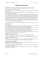
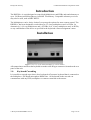
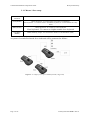
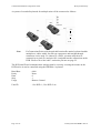
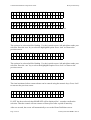
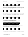
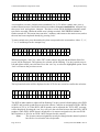
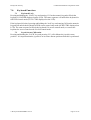
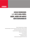
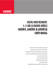
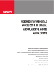
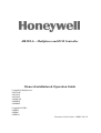
HKJX8A+ - Multiplexer and DVR Controller
Owners Installation & Operation Guide
Compatible Multiplexers:
AXCD16E
AXCD9E
AXCD4E
AXMD16E
AXMD9E
AXMD4E
Compatible DVRs:
AHDR4
AHDR9
AHDR16
Document Code Number: HMKC-001-01
Combined Installation & Operation Guide
Honeywell Security
Safety Instructions
WARNING! Read these notes before attempting to operate the unit
Refer all servicing to qualified personnel.
These products contain static electricity sensitive devices. Please take appropriate precautions
when handling.
Handle the unit with care, as improper handling may cause irreparable damage to the precision
or sensitive parts within this unit.
This information and our technical advice - whether verbal, in writing, or by way of trials - is
given in good faith but without warranty and this also applies where proprietary rights of third
parties are involved. Our advice does not release you from your obligation to check its’ validity
and to test our products’ suitability for the intended purpose(s) and use(s). The application, use
and installation of our products either in isolation or in conjunction with other products used,
provided and/or installed by you on the basis of our technical advice are beyond our control and
therefore remain entirely your own responsibility. Honeywell products are sold in accordance
with our General Conditions of Sale and Delivery.
ALL DESIGNS AND SPECIFICATIONS ARE SUBJECT TO CHANGE WITHOUT NOTICE
© Honeywell 2004
FCC Statement
NOTE: This equipment has been tested and found to comply with the limits for a Class A digital
device, pursuant to Part 15 of the FCC Rules. These limits are designed to
provide reasonable protection against harmful interference when the equipment is operated in a
commercial environment. This equipment generates, uses, and can radiate
radio frequency energy and, if not installed and used in accordance with the instruction manual,
may cause harmful interference to radio communications. Operation of this
equipment in a residential area is likely to cause harmful interference in which case the user will
be required to correct the interference at his own expense.
Compliance Information Canada
This Class A digital apparatus complies with Industry Canada Standard ICES-003.
Cet appareil numérique de la classe A est conforme à la norme NMB-003 d'Industrie Canada.
Compliance Information Europe
WARNING: This is a class A product. In a domestic environment this product may cause radio
interference in which case the user may be required to take adequate measures.
Connection to the mains supply
WARNING: The mains supply must be connected by a technically competant person and
according to the current IEE wiring regulations.
CAUTION: To avoid the risk of electric shock you must always totally isolate the mains supply
before making a connection to it.
The PSU must be wired to a double pole fuse spur with 3m separation. The 2A fuse spur must
be located close to the PSU.
Page 1 of 23
© Honeywell 2004 HMKC-001-01
Honeywell Security
Combined Installation & Operation Guide
Introduction
The HKJX8A+ is a unit designed to control both Multiplexers and DVRs and send telemetry to
up to 128 Honeywell Microspheres via RS485 TP telemetry. Compatible telemetry receivers
may also be used, such as BBV RX552.
The Multiplexers can be ‘daisy chained’ to open up the options for more camera control. The
HKJX8A+ has been designed to work with up to 32, 4 way multiplexers and / or DVRs. Or
alternatively, 14, 9 way multiplexers and / or DVRs. Or 8, 16 way multiplexers and / or DVRs,
or any combination of the above as specified in the keyboards ‘camera assignment’ menu.
Installation
Figure i Rear view of the DVR and multiplexer control handset
All connections to and from the keyboard are made to the RJ type connectors located on the rear
panel of the unit.
1.0
Keyboard Cascading
It is possible to cascade up to three slave keyboards off a master keyboard that is connected to
the multiplexer / DVR and microsphere RS485 line. All keyboards in the cascade can
communicate with any DVR, multiplexer or camera connected to the master.
© Honeywell 2004 HMKC-001-01
Page 2 of 23
Combined Installation & Operation Guide
Honeywell Security
2.1.1 Master / Slave setup
Rear Panel
Connector
Function
AUX (RS485)
Master keyboard - To connect either to a DVR or a multiplexer
Slave keyboard - To connect either to the Master keyboard, or a lower number slave keyboard
KBD (RS485)
Master keyboard - To connect to a slave keyboard
Slave keyboard - To connect to a higher number slave keyboard
CONTROL
(RS485)
RS485 telemetry output - for connection to domes or code distributor (8ITP)
A system of cascaded keyboards for a single unit will be connected as follows.
Figure ii A sample system of cascaded keyboards (single unit)
Page 3 of 23
© Honeywell 2004 HMKC-001-01
Combined Installation & Operation Guide
Honeywell Security
A system of cascaded keyboards for multiple units will be connected as follows:
DVR
Figure iii A sample system of cascaded keyboards (multiple units)
Note:
For connections between keyboards and between the master keyboard and the
multiplexer, cables with 8 way RJ type connectors and straight through
connectors can be used. To connect to a DVR, you must strip the wire
connectivity to pin 4 (D-) and pin 6 (D+) and push into the connections on the
DVR. Please refer to the cable / connector pin-outs on page 22.
The DVR unit ID and communication settings must be correctly set using the menus on the
DVR before it can be controlled using the HKJX8A+ keyboard.
Baud Rate
Parity
Data
Stop
Usage
- 9600
- None
-8
-1
- Remote Control
Unit ID
- 1 for DVR 1, 2 for DVR 2 etc.
Page 4 of 23
© Honeywell 2004 HMKC-001-01
Honeywell Security
Combined Installation & Operation Guide
RJ45 - RJ45 lead provided with
keyboard
TXNormally Blue
OUT
MUX#1
RS485
TX+
Normally Green
IN
DVR #1 Rear
RJ45 - RJ45 lead VCL part
number - 0700 0127
MUX#2
OUT
RX+ RX- TX+ TX-
RS485
IN
Figure iv Connection to Multiplexers and DVRs
The multiplexer address and communication settings must be correctly set using the menus on
the multiplexer before it can be controlled using the HKJX8A+ keyboard.
Network Type
Baud Rate
Unit Address
Protocol
- RS485
- 9600
- 001 for multiplexer 1, 002 for multiplexer 2 etc
-A
© Honeywell 2004 HMKC-001-01
Page 5 of 23
Combined Installation & Operation Guide
2.0
Honeywell Security
Dome Connection
2.1
Daisy Chain
Typical connection
from keyboard to
daisy chain
Figure v Daisy chain configuration
2.2
Star Configuration
Typical connection
from keyboard to
to ITP input
Figure vi Star configuration
Note:
Page 6 of 23
Details on termination and dome installation are covered in the dome manual.
© Honeywell 2004 HMKC-001-01
Honeywell Security
Combined Installation & Operation Guide
DVR Operation
1.0
DVR Control functions
1.1
DVR Mode
Press the ‘mode’ key, to toggle between Multiplexer and DVR mode.
1.2
DVR Selection
Pressing a number followed by the ‘Fn’ key selects a DVR to control. This also selects the last
camera controlled on that DVR (or the first camera input on that DVR if it has not been selected
previously).
1.3
Menus
Press the ‘F6’ (menu) key to enter the password screen.
Press and hold the ‘Fn’ key and press a number key to enter a number on the password screen.
Press the ‘F5’ (enter) key to enter the password and gain access to the DVR set up menus.
Navigation around these menus is achieved by using the function keys as indicated in the
following table;
Key
Function
F1
up
F2
down
F3
left
F4
right
F5
enter
enter
F6
menu
menu
Press the ‘F1’, ‘F2’, ‘F3’ or ‘F4’ keys to move around the menu pages.
Press the ‘F5’ enter key to select an option within the menus.
Press the ‘F6’ menu key to exit the current menu. If the user presses ‘F6’ when in the Set up
screen, then the DVR exits the menus and returns to normal operation.
1.4
Screen Control
The following table indicates the keys used for DVR Screen Mode control.
Key
Function
display
Display
sequence
Sequence
freeze
Freeze
© Honeywell 2004 HMKC-001-01
Page 7 of 23
Combined Installation & Operation Guide
Honeywell Security
Press the ‘display’ key to select the next display setting in the cycle of 4x4, 3x3, 2x2 and Picture
in Picture (P-I-P).
Press the ‘sequence’ key to put the DVR output into a sequence. The sequence depends on the
current display mode and set up. If the ‘sequence’ key is pressed again, the sequence stops,
displaying the current step in the sequence.
Press the ‘freeze’ key to freeze the current display. Press the key again to return to ‘live’
picture(s).
1.5
Camera Selection
Press one or two of the number keys (to enter a legal camera number), followed by the ‘camera’
key to select that number camera for full screen display on the DVR output. This also selects
the associated DVR.
Press the ‘camera’ key by itself to increment the camera selection by one.
Note:
Both of the above selection processes also make the selected camera the
telemetry camera as shown by the keyboard display. The telemetry camera
can be changed independently of the DVR display camera by putting the
keyboard in telemetry switching only mode. To enable / disable telemetry
switching only mode, press and hold the Fn key, then press the mode key.
(The PTZ LED will light when in telemetry switching only mode.)
1.6
Camera Assignment
See Chapter 6.0 - ”Using the menus” for instructions on using the LCD menu to assign cameras
to DVRs.
1.7
Recording and Playback
The following table indicates the keys used for recording and playback;
Key
Function
search
Search
play
Play / Pause
rw
Rewind
ff
Fast Forward
stop
Stop
rec
Record
counter
Counter
Fn
Function
Press the ‘search’ key to enter the search menu. Press the key again to exit the search menu.
Press the ‘counter’ key to toggle the DVR front panel display between displaying the time and
the remaining storage capacity.
If the DVR is in playback mode, press and hold the ‘Fn’ key and move the joystick right to play
the video forwards or to the left to play the video backwards. The level of force applied to the
joystick will determine the speed at which the video is played. If the joystick is returned to the
centre position, or the ‘Fn’ key is released, the shuttle is returned to the centre position and the
playback is paused.
Page 8 of 23
© Honeywell 2004 HMKC-001-01
Honeywell Security
Combined Installation & Operation Guide
If the DVR is paused in playback mode, press and hold the ‘Fn’ key and move the joystick up
to play the video forwards, image by image, or down to play the video backwards, image by
image. The video moves on to the next image every 0.5 second, whether playing forwards or
backwards.
1.8
Alarm Function
If an alarm is active, press the ‘alarm’ key to reset the DVRs outputs, including the internal
buzzer.
If the DVR is in the live monitoring mode (and no alarm is active), press the ‘alarm’ key to
display the event log. Once in the event log, it is navigated using the keys as detailed in 1.3, on
page 7.
© Honeywell 2004 HMKC-001-01
Page 9 of 23
Combined Installation & Operation Guide
Honeywell Security
Multiplexer Operation
2.0
Multiplexer Control Functions
2.1
Multiplexer Mode
Press the ‘mode’ key to toggle between Multiplexer and DVR mode.
2.2
Multiplexer Selection
Pressing a number followed by the ‘Fn’ key selects a multiplexer to control. This intelligently
selects the last camera controlled on that multiplexer (or the first camera input on that
multiplexer if it has not been selected previously).
2.3
Menus
Press the ‘F1’ key twice, then select ‘setup’ to enter the multiplexer set-up menus. Navigation
around these menus is achieved by using the function keys as indicated in the following table;
Key
Function
F1
Up
F2
Down
F3
Left
F4
Right
F5
set
Set
F6
esc
Esc
Press the ‘F1’, ‘F2’, ‘F3’ or ‘F4’ keys to move around the menu pages. Press the ‘F5’ set key to
select an option within the menus.
To exit the menus (except the main menus), select exit in the menu and then press the ‘F5’ set
key. To exit the main menus, select ‘cancel’ in the menu and then press the ‘F5’ set key. (This
will return the unit to normal operation.)
Press the ‘F6’ esc key whilst in the main menus only to exit (and return to normal operation).
Page 10 of 23
© Honeywell 2004 HMKC-001-01
Honeywell Security
Combined Installation & Operation Guide
2.4
Screen Control
The following table indicates the keys used for Multiplexer Screen control.
Key
Function
display
Display
sequence
Sequence
freeze
Freeze
play
Toggle VCR Input
search
Digital Zoom
Press the ‘display’ key to select the next display setting (in the cycle of 4x4, 3x3, 2x2 and PIP)
Press the ‘sequence’ key to put the Multiplexer output into a sequence (the sequence depends
on the current display mode and set up). If the key is pressed again, the sequence stops.
(Displaying the current step in the sequence.)
Press the ‘freeze’ key to freeze the current display. Press the key again to return to the ‘live’
pictures.
Press the ’play’ key to select the VCR input for display. Press the key again to return to the live
picture(s).
Press the ‘search’ key to select the ‘zoom’ mode (see below). Once in zoom mode, press the
‘search’ key again to exit ‘zoom’ mode.
To use the zoom feature (once in zoom mode), press the following keys to move the zoomed
area..
Key
Function
F1
Up
F2
Down
F3
Left
F4
Right
2.5
Spot Monitor Selection
Spot monitors 1 to 4 are selected by first pressing a number key, followed by the ‘monitor’ key.
This will select the spot monitor for control by the keyboard. The spot monitor number will be
displayed no the LCD.
Note:
Telemetry commands will be sent to the camera displayed on the MAIN
monitor until a camera is selected on the SPOT monitor.
Pressing ‘0’ followed by the ‘monitor’ key returns the keyboard control back to the main
monitor. (‘MAIN’ will be displayed on the LCD.)
Note:
Pressing ‘F6’ (Menu), ‘display’, ‘alarm’, and ‘play’ will also put the
multiplexer back to main monitor control.
© Honeywell 2004 HMKC-001-01
Page 11 of 23
Combined Installation & Operation Guide
Honeywell Security
2.6
Camera Selection
Pressing a number followed by the ‘camera’ key selects a camera to display. This intelligently
selects the associated multiplexer (e.g. if camera 18 is selected and camera 18 is assigned to
input 2 on multiplexer 2 then the second input on multiplexer 2 is selected).
Pressing the ‘camera’ key alone increments the camera selection.
Note:
Both of the above selection processes also make the selected camera the
telemetry camera as shown by the keyboard display. The telemetry camera
can be changed independently of the Multiplexer display camera by putting
the keyboard in telemetry switching only mode. To enable / disable telemetry
switching only mode, press and hold the ‘Fn’ key, then press the ‘mode’ key.
(The PTZ LED will light when in telemetry switching only mode.)
2.7
Camera Assignment
See for instructions on using the LCD menu to assign cameras to multiplexers.
Page 12 of 23
© Honeywell 2004 HMKC-001-01
Honeywell Security
3.0
Combined Installation & Operation Guide
Camera Control Functions
3.1
Pan and Tilt
Very precise control of pan and tilt can be achieved using the joystick. The speed of pan and tilt
is relative to the amount of movement applied to the joystick.
3.2
Turn 180°
This function allows the camera to view a person who is walking underneath the camera.
Press the auto 180°’ button to pan the camera 180°.
The camera will pan 180° at the maximum speed. (Up to 400° per second.)
3.3
Zoom
Rotate the top of the joystick clockwise to zoom in.
Rotate the top of the joystick anti-clockwise to zoom out.
3.4
Focus and Iris
Press the auto button above the focus control buttons to toggle the camera in and out of
‘auto-focus’ mode, if the feature is available on the selected camera / receiver.
Press the ‘+’ (FAR) or ‘-’ (NEAR) buttons to manually focus the camera. (The camera will
automatically change to ‘manual focus’ mode if one of these two buttons is pressed.)
Press the auto button above the iris control button to toggle the camera in and out of ‘auto-iris’
mode, if the feature is available on the selected camera / receiver. Press the ‘+’ (OPEN) or ‘-’
(CLOSE) buttons to manually alter the camera iris. (The camera will automatically change to
‘manual iris’ mode if one of these two buttons is pressed.)
3.5
Wash, Wipe and Auxiliary Functions
If the receiver being controlled has WASH and WIPE functions, they are controlled as follows:
FOR WIPE.
Press the ‘wipe’ button to activate the wiper.
Press the ‘wipe’ button again to turn off the wiper.
FOR WASH.
Press and hold the ‘wash’ button to activate the washer.
Release the ‘wash’ button to turn off the washer.
If the receiver has a separate momentary function (auxiliary), it is controlled as follows:
Press the ‘0’ button, then press and hold the ‘aux’ button to activate the auxiliary function.
Release the ‘aux’ button to turn off the auxiliary function.
Note:
The ‘aux’ button illumination is not altered by this operation as it is used to
monitor ‘Change Over’ Orbiter Microspheres.
3.6
Manual Change Over (Change Over Orbiter Microspheres only)
The operator can force the camera to change from MONO to COLOUR or COLOUR to MONO
by pressing the ‘aux’ button. The camera will automatically change back dependant on the level
of illumination.
If the camera is in the mode selected by the operator (and is different to the mode that the camera
would have automatically selected), the ‘aux’ button is illuminated.
If the camera is in the mode that the camera has automatically selected, the ‘aux’ button is
not illuminated.
© Honeywell 2004 HMKC-001-01
Page 13 of 23
Combined Installation & Operation Guide
4.0
Honeywell Security
Presets and Tours
4.1
To Define a Preset
For example, to define Preset 1.
Move the selected camera to view the desired preset position, using the joystick, zoom, focus
and iris buttons.
Press and hold the ‘preset’ button.
Press button ‘1’.
Release the ‘preset’ button.
The current position of the camera has now been defined as Preset 1.
Up to 128 presets can be defined, and these are numbered 0 - 127.
4.2
To Seek a Preset
For Example, to seek Preset 1.
Press button ‘1’.
Press the ‘preset’ button.
The camera will now move at the maximum speed to the previously defined Preset 1.
The user may also select presets 1 - 4 by single button presses, using the buttons labelled ‘preset’
‘1’ to ‘4’.
Note:
Page 14 of 23
A preset seek will only occur if the preset has previously been defined
© Honeywell 2004 HMKC-001-01
Honeywell Security
Combined Installation & Operation Guide
4.3
To Start a Tour of Presets
A Microsphere can store four different preset tours. After programming the tours, as detailed in
the next sections, they may be recalled in the following way.
Press the number button that corresponds to the tour number, either ‘1’,
‘2’, ‘3’, or ‘4’.
Press the ‘autopan’ button.
4.4
To Define a Simple Tour
For example, to define a tour for three preset positions in memory as ‘Tour 1’.
First, define the three preset positions, as detailed in section 4.1, above.
Press button ‘1’, then press and hold the ‘autopan’ button. (This will
define ‘Tour 1’.)
Press button ‘1’, then press the‘preset’ button. (This selects the first
preset in ‘Tour 1’.)
Press button ‘2’, then press the ‘preset’ button. (This selects the second
preset in ‘Tour 1’.)
Press button ‘3’, then press the ‘preset’ button. (This selects the third
preset in ‘Tour 1’.)
Release the ‘autopan’ button.
The tour is now set up. To operate ‘Tour 1’
Press button ‘1’, then press the ‘autopan’ button.
The tour will now be set with a standard speed of 30°/sec and the dwell time at each preset set
to a standard 60 seconds.
4.5
To Vary the Standard Speed of a Tour
For example, to define a tour (As set in 4.4, above.) in memory as ‘Tour 2’ with different speeds
between preset positions.
Press button ‘2’, then press and hold the ‘autopan’ button. (This will
define ‘Tour 2’.)
Press button ‘1’, then press the ‘preset’ button. (This selects the first
preset in ‘Tour 2’.)
Press button ‘5’, then press button ‘0’, then press the ‘180°’ button.
(This defines 50°/sec to this preset position.)
Press button ‘2’, then press the ‘preset’ button. (This selects the second
preset in ‘Tour 2’.)
Press button ‘1’, then press button ‘0’, then press button ‘0’, then press
the ‘180°’ button. (This defines 100°/ sec to this preset position.)
Press button ‘3’, then press the ‘preset’ button. (This selects the third
preset in ‘Tour 2’.)
Press button ‘2’, then press the ‘180°’ button. (This defines 2°/sec to
this preset position.)
Release the ‘autopan’ button.
The tour is now set up. To operate ‘Tour 2’
Press button ‘2’, then press the ‘autopan’ button.
© Honeywell 2004 HMKC-001-01
Page 15 of 23
Combined Installation & Operation Guide
Note:
Honeywell Security
The range of speeds that can be selected goes from ‘1’ = 1°/sec up to ‘100’ =
100°/sec. To select the maximum seek speed, press ‘0’.
4.6
To Vary the Standard Speeds and Dwell Times of a Tour
For example, to define a tour (As set in 4.5, above.) in memory as ‘Tour 3’ with different dwell
times between preset positions.
Press button ‘3’, then press and hold the ‘autopan’ button. (This will
define ‘Tour 3’.)
Press button ‘1’, then press the ‘preset’ button. (This selects the first
preset in ‘Tour 3’.)
Press button ‘5’, then press button ‘0’, then press the ‘180°’ button.
(This defines 50°/sec to this preset position.)
Press button ‘1’, then press button ‘0’, then press the ‘counter’ button.
(This defines a 10 second dwell time at this preset position.)
Press button ‘2’, then press the ‘preset’ button. (This selects the second
preset in ‘Tour 3’.)
Press button ‘1’, then press button ‘0’, then press button ‘0’, then press
the ‘180°’ button. (This defines 100°/sec to this preset position.)
Press button ‘1’, then press button ‘6’, then press the ‘counter’ button.
(This defines a 16 second dwell time at this preset position.)
Press button ‘3’, then press the ‘preset’ button. (This selects the third
preset in ‘Tour 3’.)
Press button ‘2’, then press the ‘180°’ button. (This defines 2°/ sec to
this preset position.)
Press button ‘1’, then press button ‘4’, then press the ‘counter’ button.
(This defines a 14 second dwell time at this preset position.)
Release the ‘autopan’ button.
The tour is now set up. To operate ‘Tour 3’
Press button ‘3’, then press the ‘autopan’ button.
Note:
The range of the dwell times that can be set varies from 1 to 254 seconds.
Entering a time of ‘0’ will select 1 second dwell time.
4.7
Alarm Activation during Tour Programming
If an alarm is activated on a camera whilst any keyboard is being used to program a tour for that
camera, the programming will be interrupted at the point of activation. (The tour will also
require re-programming.)
4.8
To Stop a Tour of Presets
Press the ‘autopan’ button. (This will turn off the tour.)
The tour will also stop if the telemetry buttons or the joystick are used to control the camera.
4.9
To Restart a Tour of Presets
Press the ‘autopan’ button. (This will start the last tour that the unit was carrying out.)
Page 16 of 23
© Honeywell 2004 HMKC-001-01
Honeywell Security
5.0
Combined Installation & Operation Guide
Enhanced functions
The keyboard can access the following enhanced functions:
Home Preset or Tour
Remote Reset
Privacy Zones
Mimic Tours
These functions are explained in greater detail in 6.1, below.
6.0
Using the menus
The following map shows the menu layout and the keypresses necessary to navigate through the
various keyboard menus
6.1
Menu Navigation
1
MAIN SCREEN
Define
Mimic
Lock 9090
Lock
Lock 5858
Lock 4747
Lock
Lock
Lock
2
MICROSPHERE
FUNCTIONS
11
MIMIC RECORDING
12
MASTER/SLAVE SET
14
CAMERA ASSIGNMENT
Lock
Home
Lock
Lock
Privacy
6
PRIVACY
3
HOME DEFINITION
Preset/
Tour Lock
1 SECOND
OFF
4
HOME TIME
5
HOME OFF
1 SECOND
Reset
SLVn/
MSTR
13
KEYBOARD
SELECTION
7
RESET
30 SECONDS
12 SECONDS
POWER
30 SECONDS
CAMERA
FACTORY
8
POWER
9
FACTORY
10
CAMERA
The arrows on the diagram above detail the keypresses required to move between the screens.
The main screen is shown below.
© Honeywell 2004 HMKC-001-01
Page 17 of 23
Combined Installation & Operation Guide
Honeywell Security
C A M E R A
n n n
M U X
n n
P R E S E T
n n n
S P O T
C A M E R A
n n n
D V R
n
n n
P R E S E T
n n n
S C R N
C T R L
1. Main Screen - Press ‘mode’ key to toggle between Mux and DVR control.
A U X
=
S E T
H O M E
P R I
2. Microsphere Functions
L O C K
V A C Y
=
E N D
R E S E T
The option to be selected will be flashing. Use the joystick to move left and right to make your
selection. Press the ‘aux’ key to select the highlighted option. Press ‘lock’ to return to the
previous screen
A U X
=
S E T
P R E S E T
3. Home Definition
L O C K
=
T O U R
E N D
O F F
The option to be selected will be flashing. Use the joystick to move left and right to make your
selection. Press the ‘aux’ key to select the highlighted option. Press ‘lock’ to return to the
previous screen.
H O M E
E N T E R
4. Home Time
L O C K
T I
M E O U T
=
E N D
n n n
The time in minutes before return to home can be entered using the numeric keys. Press ‘lock’
to return to the previous screen.
H O M E
O F F
5. Home Off
If ‘OFF’ has been selected, then HOME OFF will be displayed for 1 second to confirm the
selection. Then the camera will not return to a Home preset after a priod of inactivity.
After one second, the screen will automatically revert to the Home Definition screen.
Page 18 of 23
© Honeywell 2004 HMKC-001-01
Honeywell Security
A U X
=
P R E S E T
6. Privacy
Combined Installation & Operation Guide
S E T
L O C K
n n n
P R I
=
E N D
V A C Y
Selecting the Privacy option from the Microsphere Functions screen will display the screen
above. The preset can be selected by moving the joystick up and down. Using the ‘aux’ key will
toggle the status between privacy on and privacy off. Press ‘lock’ to return to the previous
screen.
A U X
= S E N D
P O W E R
7. Reset
L O C K
C A M E R A
=
E N D
F A C T O R Y
Selecting the Reset option from the Microsphere Functions screen will display the screen
above.The option to be selected will be flashing. Use the joystick to move left and right to make
your selection. Press the ‘aux’ key to select the highlighted option. Press ‘lock’ to return to the
previous screen.
P O W E R
U P
R E S E T
8. POWER
If ‘POWER’ has been selected, then ‘POWER UP RESET’ will be displayed, and the keyboard
will be locked for 30 seconds whilst the microsphere resets.
F A C T O R Y
R E S E T
9. FACTORY
If ‘FACTORY’ has been selected, then ‘FACTORY RESET’ will be displayed, and the
keyboard will be locked for 30 seconds whilst the microsphere resets.
C A M E R A
R E S E T
10. CAMERA
If ‘CAMERA’ has been selected, then ‘CAMERA RESET’ will be displayed, and the keyboard
will be locked for 12 seconds whilst the microsphere camera resets.
© Honeywell 2004 HMKC-001-01
Page 19 of 23
Combined Installation & Operation Guide
C A M E R A
n n n
R E C O R D I
11. Mimic Recording
N G
Honeywell Security
M U X n
M I
M I
P n n n
C
n
A microsphere can store 4 mimic tours (numbered 5 to 8). To define a mimic tour, press a
number button between 5 and 8 (the mimic tour number) than press and hold the ‘autopan’ key,
then press ‘lock’ and replease ‘autopan’. The above screen will be highlighted and the mimic
tour can be recorded. Whilst the mimic tour is being recorded, ‘RECORDING MIMIC n’
flashes on and off. This menu times out after 3 minutes, and returns to the main screen, unless
the tour has been completed already by pressing ‘lock’.
To start a mimic tour, press the number key that corresponds to the tour number, either ‘5’, ‘6’,
‘7’ or ‘8’ and then press the ‘autopan’ key.
A U X
=
S E T
L O C K
=
E N D
M S T R
S L V 1
12. Master/Slave Set
S L V 2
S L V 3
Whilst pressing the ‘lock’ key, enter 4747 on the numeric keypad and the Master/Slave Set
screen will be displayed. The option to be selected will be flashing. Use the joystick to move
left and right to make your selection. Press the ‘aux’ key to select the highlighted option. Press
‘lock’ to return to the previous screen.
S L A V E
n
K E Y B O A R D
13. Keyboard Selection
The keyboard selection will be displayed on the LCD for one second to confirm the selection.
A U X
=
S E T
L O C K
C A M n n n
D V R n n
14. Camera Assignment
=
E N D
M U X n n
The DVR or Mux number to adjust will be flashing. Use the joystick left and right to select DVR
or MUX, and joystick up and down to select the camera. Cameras are assigned to DVRs / MUXs
in blocks of 4, 9 or 16. If the DVR / MUX number can be adjusted, the ‘AUX=SET’ message
will be displayed. Pressing the ‘aux’ key will cycle the selection between the last DVR / MUX
number (if this DVR / MUX doesn’t already have 16 cameras assigned to it), the next DVR /
MUX number, or NO (for no DVR / MUX assigned to this camera).
Note:
The systems camera assignment can only be changed on the master keyboard,
but can be viewed on the slave keyboards.
Page 20 of 23
© Honeywell 2004 HMKC-001-01
Honeywell Security
7.0
Combined Installation & Operation Guide
Keyboard Functions
7.1
Keyboard Lock
Pressing and holding the ‘LOCK’ key and entering 1212 on the numeric keypad will lock the
keyboard. (LOCKED displayed on the LCD). The same sequence will unlock the keyboard in
full DVR control mode (FULL CTRL displayed on the LCD).
If the keyboard is locked, pressing and holding the ‘lock’ key and entering 3434 on the numeric
keypad will unlock the keyboard in DVR screen control only mode (SCRN CTRL displayed on
LCD). The same sequence will lock the keyboard if in screen control mode, or convert the
keyboard to screen control mode if in full control mode.
7.2
Joystick Auto Calibration
Pressing and holding the ‘LOCK’ key and pressing ‘F6’ will calibrate the joystick centre
position. It is important that the joystick is at its centre détente position when this is performed.
© Honeywell 2004 HMKC-001-01
Page 21 of 23
Combined Installation & Operation Guide
8.0
Honeywell Security
Connector Pin Assignments - for reference
Viewed on wiring input side of plug.
8.1
KBD
PIN
SIGNAL
1
Link TX D+
2
Link TX D-
4
Link RX D-
5
GND
6
Link RX D+
8.2
Usual Colour
1 2 3 4 5 6 7 8
AUX
PIN
SIGNAL
1
DVR RX+
2
DVR RX-
4
DVR TX D-
5
GND
6
DVR TX D+
8.3
Usual Colour
1 2 3 4 5 6 7 8
Blue
Green
CONTROL
PIN
SIGNAL
Usual Colour
1
DATA +
White / Orange
2
DATA -
Orange
3
GND
4
TXK OUT
5
TXK IN
8.4
Page 22 of 23
1 2 3 4 5 6 7 8
POWER
PIN
SIGNAL
1
GND
4
+12 VOLTS
1 2 3 4
© Honeywell 2004 HMKC-001-01
Honeywell Security
9.0
Combined Installation & Operation Guide
Techincal Specifications
Features
AKJX8A+
Max. dome control
128
Max. DVR/Multiplexer
control
Up to 32 x 4-way, 14 x 9-way or 8 x 16-way or any combination of the
above as specified in the keyboards “camera assignment” menu
Compatible DVRs and
Multiplexers
DVRs: AHDR4X, AHDR9X, AHDR16X
Multiplexers: AXCD4EX, AXCD9EX, AXCD16EX, AXMD4EX,
AXMD9EX, AXMD16EX
Max. linked keyboards
1 master and 3 slaves
RS485 connections
3
Connectors
3
LCD
2 rows of 20 characters
DVR/Multiplexer functions controllable via
HKJX8A+
DVRs
Full screen cameras 1 to 16,
Picture in picture, 2x2 picture,
3x3 picture, 4x4 picture,
Picture sequence, picture freeze,
Search, play, rewind, fast forward,
Stop, record, time/counter,
Shuttle forwards/backwards,
Alarm cancel, event log menu,
Search menu, main menu
Multiplexers
Full screen cameras 1 to 16,
Picture in picture, 2x2 picture,
3x3 picture, 4x4 picture,
picture sequence, picture freeze,
4 spot monitors, zoom mode,
Tape input selection, menus
Telemetry functions
controllable via HKJX8A+
Variable speed pan/tilt via joystick
Zoom via twist joystick
Focus near, focus far, auto focus
Iris open, iris close, auto iris
Colour/mono change-over
Auto 180° turn around
128 presets (programming and selection)
4 rapid preset selections (presets 1 to 4)
4 preset tours (programming and selection)
4 mimic tours (programming and slection)
Privacy zone programming (via LCD menus)
Home preset / tour programming (via LCD menus)
Power and factory reset (via LCD menus)
Wash
Wipe
Dimensions (mm) WxHxD
355 x 60 x 180
Weight (kg) approximate
3.0
Power supply provided
12V DC regulated to 300mA
Operating temperature
0°C to 40°C
© Honeywell 2004 HMKC-001-01
Page 23 of 23