1
Symbol MT2070/MT2090
User Guide
MT2070/MT2090
User Guide
72E-117859-02
Revision A
September 2009
iv
Symbol MT2070/MT2090 User Guide
© 2009 by Motorola, Inc. All rights reserved.
No part of this publication may be reproduced or used in any form, or by any electrical or mechanical means,
without permission in writing from Motorola. This includes electronic or mechanical means, such as
photocopying, recording, or information storage and retrieval systems. The material in this manual is subject to
change without notice.
The software is provided strictly on an “as is” basis. All software, including firmware, furnished to the user is on
a licensed basis. Motorola grants to the user a non-transferable and non-exclusive license to use each
software or firmware program delivered hereunder (licensed program). Except as noted below, such license
may not be assigned, sublicensed, or otherwise transferred by the user without prior written consent of
Motorola. No right to copy a licensed program in whole or in part is granted, except as permitted under
copyright law. The user shall not modify, merge, or incorporate any form or portion of a licensed program with
other program material, create a derivative work from a licensed program, or use a licensed program in a
network without written permission from Motorola. The user agrees to maintain Motorola’s copyright notice on
the licensed programs delivered hereunder, and to include the same on any authorized copies it makes, in
whole or in part. The user agrees not to decompile, disassemble, decode, or reverse engineer any licensed
program delivered to the user or any portion thereof.
Motorola reserves the right to make changes to any software or product to improve reliability, function, or
design.
Motorola does not assume any product liability arising out of, or in connection with, the application or use of
any product, circuit, or application described herein.
No license is granted, either expressly or by implication, estoppel, or otherwise under any Motorola, Inc.,
intellectual property rights. An implied license only exists for equipment, circuits, and subsystems contained in
Motorola products.
MOTOROLA and the Stylized M Logo and Symbol and the Symbol logo are registered in the US Patent &
Trademark Office. Bluetooth is a registered trademark of Bluetooth SIG. Microsoft, Windows and ActiveSync
are either registered trademarks or trademarks of Microsoft Corporation. All other product or service names
are the property of their respective owners.
Motorola, Inc.
One Motorola Plaza
Holtsville, New York 11742-1300
http://www.motorola.com/enterprisemobility.
Patents
This product is covered by one or more of the patents listed on the Web site:
http://www.motorola.com/enterprisemobility/patents.
Warranty
The MT2000 Series is warranted against defects in workmanship and materials for a period of 36 months from
date of shipment, provided that the product remains unmodified and is operated under normal and proper
conditions
For the complete Motorola hardware product warranty statement, go to:
http://www.motorola.com/enterprisemobility/warranty.
v
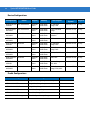
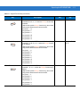
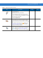
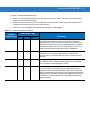
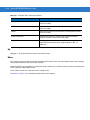
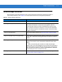
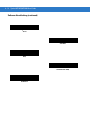
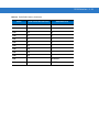
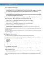
Revision History
Changes to the original manual are listed below:
Change
Date
Description
-01 Rev A
8/2009
Initial release.
-02 Rev A
9/2009
Keypad, battery information and accessory updates.
vi
Symbol MT2070/MT2090 User Guide
Table of Contents
Patents........................................................................................................................... iv
Warranty ........................................................................................................................ iv
Revision History ............................................................................................................. v
About This Guide
Introduction ....................................................................................................................
Documentation Set ..................................................................................................
Device Configurations..............................................................................................
Cradle Configurations ..............................................................................................
Chapter Descriptions .....................................................................................................
Notational Conventions..................................................................................................
Related Documents .......................................................................................................
Service Information........................................................................................................
xix
xix
xx
xx
xxi
xxii
xxiii
xxiii
Chapter 1: Getting Started
Introduction ...................................................................................................................
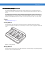
Unpacking .....................................................................................................................
MT20X0 ..................................................................................................................
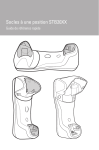
Cradles ....................................................................................................................
STB2000-C10007R Single Slot Charge Only with ActiveSync .........................
STB2000-F10007R Forklift Single Slot Charge Only ........................................
STB2078-C10007WR Single Slot Multi-interface Bluetooth .............................
STB2000-C40007R Four Slot Charge Only ......................................................
STB2000-C40017R Four Slot Ethernet ............................................................
SAC2000-4000CR Four Slot Spare Battery Charger ........................................
Accessories ..................................................................................................................
Features ........................................................................................................................
Cradle Features ............................................................................................................
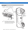
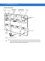
Single Slot - Front View and Connections ..............................................................
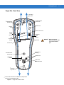
Single Slot - Back View ...........................................................................................
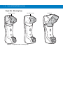
Single Slot - Mounting Cups ...................................................................................
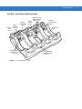
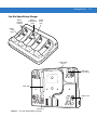
Four Slot - Front View and Connections .................................................................
Four Slot - Back View .............................................................................................
1-1
1-1
1-1
1-1
1-1
1-2
1-2
1-2
1-2
1-2
1-2
1-3
1-4
1-4
1-5
1-6
1-7
1-8
viii
Symbol MT2070/MT2090 User Guide
Four Slot Spare Battery Charger ............................................................................
Host Interfaces ..............................................................................................................
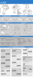
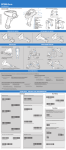
Out-of-Box Startup ........................................................................................................
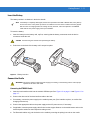
Insert the Battery .....................................................................................................
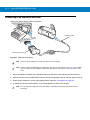
Connect the Cradle .................................................................................................
Connecting the STB20XX Cradle .....................................................................
Connecting STB2000-F Cradle .........................................................................
Changing the Host Interface .............................................................................
Supplying Power to the Cradle ...............................................................................
Using the USB Interface to Supply Power ........................................................
Insert the Device in the Cradle ................................................................................
Charge the Device Battery in the Cradle ................................................................
Charging Indicator/LED .....................................................................................
Configure the Device ..............................................................................................
Battery Charging ...........................................................................................................
Battery Safety ...............................................................................................................
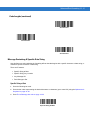
Security Implementation/Protection From Counterfeit Batteries .............................
Motorola Battery Safety Recommendations For Users ...........................................
Proper and Safe Battery Disposal & Recycling: ......................................................
Sending Data to the Host Computer .............................................................................
Cable Mode .............................................................................................................
Bluetooth Mode .......................................................................................................
Pairing ...............................................................................................................
Lost Connection to Host ....................................................................................
Radio Communications .................................................................................................
Startup ..........................................................................................................................
Suspending/Powering Off the Device ...........................................................................
Resetting the Device .....................................................................................................
Turning the WLAN Radio On and Off ...........................................................................
Waking the Device ........................................................................................................
Battery Removal ...........................................................................................................
Spare Battery Charging ................................................................................................
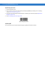
Lanyard .........................................................................................................................
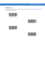
Screen Protector ...........................................................................................................
1-9
1-10
1-10
1-11
1-11
1-11
1-12
1-12
1-12
1-12
1-13
1-13
1-13
1-13
1-14
1-15
1-15
1-15
1-16
1-17
1-17
1-17
1-17
1-17
1-18
1-18
1-18
1-18
1-18
1-18
1-19
1-19
1-20
1-21
Chapter 2: Operating the MT2070/MT2090
Introduction ...................................................................................................................
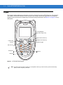
Keypad ..........................................................................................................................
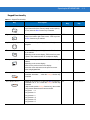
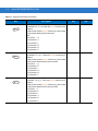
Keypad Functionality ...............................................................................................
Using the Keypad to Navigate Applications ..................................................................
Entering Information .....................................................................................................
Entering Information Using the Keypad ..................................................................
Screen Icons .................................................................................................................
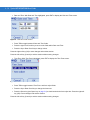
Home Screen ................................................................................................................
Menu .......................................................................................................................
User Settings ....................................................................................................
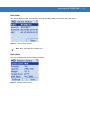
Device Status ....................................................................................................
Battery Status ...................................................................................................
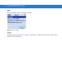
About .................................................................................................................
2-1
2-2
2-3
2-8
2-8
2-8
2-9
2-11
2-12
2-13
2-15
2-15
2-16
Table of Contents
Suspend ............................................................................................................
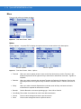
Scan Item ......................................................................................................................
Quantity ...................................................................................................................
Item .........................................................................................................................
Menu .......................................................................................................................
Options ..............................................................................................................
About... ..............................................................................................................
Close .................................................................................................................
Close .......................................................................................................................
Scan Inventory ..............................................................................................................
Location ..................................................................................................................
Quantity ...................................................................................................................
Item .........................................................................................................................
Menu .......................................................................................................................
View Inventory ..................................................................................................
MCL ..............................................................................................................................
Scan Transmit .........................................................................................................
Scan Inventory ........................................................................................................
View Data ..........................................................................................................
Send Data .........................................................................................................
Delete Last ........................................................................................................
Image Viewer (Devices Equipped with Imagers) ..........................................................
Menu .......................................................................................................................
Preview On .......................................................................................................
Open .................................................................................................................
Options ..............................................................................................................
About .................................................................................................................
Close .................................................................................................................
Config ...........................................................................................................................
Wireless Companion (MT2090 Only) ......................................................................
Find WLANs ......................................................................................................
Manage Profiles ................................................................................................
Creating a New Profile ......................................................................................
Profile ID ...........................................................................................................
Profile Name .....................................................................................................
ESSID ...............................................................................................................
Operating Mode ................................................................................................
Channel .............................................................................................................
Security Mode ...................................................................................................
Security Mode ...................................................................................................
Authentication Type ..........................................................................................
Tunneled Authentication ...................................................................................
User Certificate Selection .................................................................................
Advanced Identity .............................................................................................
Credential Cache Options .................................................................................
Encryption .........................................................................................................
IP Address Entry .....................................................................................................
Transmit Power .................................................................................................
Battery Usage ...................................................................................................
Manage Certificates ..........................................................................................
2-16
2-17
2-17
2-17
2-18
2-18
2-19
2-19
2-19
2-20
2-20
2-21
2-21
2-21
2-21
2-26
2-27
2-28
2-29
2-29
2-29
2-30
2-30
2-30
2-30
2-31
2-31
2-31
2-32
2-32
2-33
2-33
2-34
2-35
2-35
2-35
2-35
2-37
2-38
2-39
2-40
2-40
2-42
2-48
2-49
2-51
2-56
2-58
2-59
2-60
ix
x
Symbol MT2070/MT2090 User Guide
Manage PACs ...................................................................................................
Options ..............................................................................................................
Wireless Status .................................................................................................
Wireless Diagnostics .........................................................................................
Log On/Off ........................................................................................................
Enable/Disable Radio .......................................................................................
Settings ...................................................................................................................
General Parameters ..........................................................................................
Bar Code Settings .............................................................................................
Rapid Deployment ..................................................................................................
MSP Agent ..............................................................................................................
BTExplorer ..............................................................................................................
Establish a New Connection .............................................................................
Add a Bluetooth Service ...................................................................................
Turn Bluetooth On/Off .......................................................................................
Miscellaneous Bluetooth Settings .....................................................................
Configure USB ........................................................................................................
Up ...........................................................................................................................
Menu .......................................................................................................................
Utilities ..........................................................................................................................
File Explorer ............................................................................................................
File Explorer Functionality .................................................................................
File Explorer Keypad Usage .............................................................................
Task Manager .........................................................................................................
Resetting the MT20X0 ..................................................................................................
Performing a Warm Boot ........................................................................................
Performing a Cold Boot ...........................................................................................
Waking the MT20X0 .....................................................................................................
File System Directory Structure ....................................................................................
2-64
2-67
2-73
2-78
2-82
2-83
2-84
2-84
2-84
2-85
2-85
2-86
2-86
2-88
2-90
2-90
2-93
2-94
2-94
2-95
2-95
2-95
2-96
2-96
2-97
2-97
2-97
2-98
2-98
Chapter 3: Scanning
Introduction ...................................................................................................................
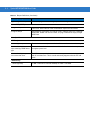
Beeper Definitions ........................................................................................................
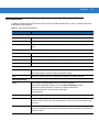
LED Definitions .............................................................................................................
Scanning in Hand-Held Mode .......................................................................................
Scanning with the MT20X0 .....................................................................................
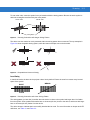
Aiming .....................................................................................................................
Imager Aiming ...................................................................................................
Laser Aiming .....................................................................................................
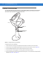
Scanning in Presentation Mode ....................................................................................
Scanning Considerations ........................................................................................
Decode Distances .........................................................................................................
3-1
3-1
3-3
3-4
3-4
3-4
3-4
3-5
3-6
3-7
3-8
Chapter 4: Radio Communications
Introduction ...................................................................................................................
Scanning Sequence Examples ...............................................................................
Errors While Scanning ............................................................................................
Radio Communications Parameter Defaults .................................................................
4-1
4-1
4-1
4-2
Table of Contents
Wireless Beeper Definitions ..........................................................................................
Radio Communications Host Types .............................................................................
Bluetooth Technology Profile Support ..........................................................................
Master/Slave Set Up ...............................................................................................
Master ...............................................................................................................
Slave .................................................................................................................
Bluetooth Friendly Name ........................................................................................
Discoverable Mode .................................................................................................
HID Host Parameters ....................................................................................................
HID Country Keyboard Types (Country Codes) ......................................................
HID Keyboard Keystroke Delay ..............................................................................
HID CAPS Lock Override ........................................................................................
HID Ignore Unknown Characters ............................................................................
Emulate Keypad ......................................................................................................
HID Keyboard FN1 Substitution ..............................................................................
HID Function Key Mapping .....................................................................................
Simulated Caps Lock ..............................................................................................
Convert Case ..........................................................................................................
Auto-reconnect Feature ................................................................................................
Reconnect Attempt Beep Feedback .......................................................................
Reconnect Attempt Interval .....................................................................................
Auto-reconnect in Bluetooth Keyboard Emulation (HID Slave) Mode .....................
Out of Range Indicator ..................................................................................................
MT20X0(s) To Cradle Support ......................................................................................
Modes of Operation ................................................................................................
Point-to-Point Communication ..........................................................................
Multipoint-to-Point Communication ...................................................................
Parameter Broadcast (Cradle Host Only) ...............................................................
Pairing .....................................................................................................................
Pairing Modes ...................................................................................................
Lock Override ....................................................................................................
Pairing Methods ................................................................................................
Unpairing ...........................................................................................................
Pairing Bar Code Format ........................................................................................
Pairing Bar Code Example ................................................................................
Connection Maintenance Interval ...........................................................................
Considerations ..................................................................................................
Bluetooth Security .........................................................................................................
Authentication .........................................................................................................
PIN Code ................................................................................................................
Variable PIN Code ............................................................................................
Encryption ...............................................................................................................
Chapter 5: User Preferences & Miscellaneous Scanner Options
Introduction ...................................................................................................................
Scanning Sequence Examples .....................................................................................
Errors While Scanning ..................................................................................................
User Preferences/Miscellaneous Options Parameter Defaults .....................................
User Preferences ..........................................................................................................
4-3
4-4
4-6
4-6
4-6
4-6
4-7
4-7
4-8
4-8
4-10
4-10
4-11
4-11
4-12
4-12
4-13
4-13
4-14
4-14
4-15
4-17
4-18
4-19
4-19
4-19
4-19
4-20
4-20
4-21
4-21
4-22
4-22
4-23
4-23
4-23
4-24
4-26
4-26
4-27
4-27
4-28
5-1
5-2
5-2
5-2
5-4
xi
xii
Symbol MT2070/MT2090 User Guide
Set Default Parameter ............................................................................................
Host Mode ...............................................................................................................
Decode Pager Motor Enable ...................................................................................
Parameter Bar Code Scanning ...............................................................................
Beep After Good Decode ........................................................................................
Beeper Tone ...........................................................................................................
Beeper Volume .......................................................................................................
Hand-Held Trigger Mode ........................................................................................
Decode Session Timeout ........................................................................................
Picklist Mode ...........................................................................................................
Timeout Between Decodes, Same Symbol ............................................................
Hand-Held Decode Aiming Pattern .........................................................................
Decoding Illumination (Hand-Held Mode only) .......................................................
Batch Mode .............................................................................................................
Modes of Operation ..........................................................................................
Miscellaneous Parameters ...........................................................................................
Transmit Code ID Character ...................................................................................
Prefix/Suffix Values .................................................................................................
Scan Data Transmission Format ............................................................................
FN1 Substitution Values .........................................................................................
Scan Data Transmission Format (continued) .........................................................
Transmit “No Read” Message .................................................................................
5-4
5-5
5-6
5-7
5-7
5-8
5-9
5-10
5-10
5-11
5-12
5-12
5-13
5-14
5-14
5-16
5-16
5-17
5-18
5-19
5-19
5-20
Chapter 6: Imaging Preferences
Introduction ...................................................................................................................
Scanning Sequence Examples .....................................................................................
Errors While Scanning ..................................................................................................
Imaging Preferences Parameter Defaults .....................................................................
Imaging Preferences .....................................................................................................
Operational Modes ..................................................................................................
Decode Mode ....................................................................................................
Snapshot Mode .................................................................................................
Image Capture Illumination .....................................................................................
Snapshot Mode Timeout .........................................................................................
Snapshot Aiming Pattern ........................................................................................
Image Cropping ......................................................................................................
Crop to Pixel Addresses .........................................................................................
Image Brightness (Target White) ............................................................................
JPEG Quality and Size Value .................................................................................
Image File Format Selector .....................................................................................
Signature Capture ...................................................................................................
Output File Format ............................................................................................
Signature Capture File Format Selector .................................................................
Signature Capture Width .........................................................................................
Signature Capture Height .......................................................................................
Signature Capture JPEG Quality ............................................................................
Video View Finder ...................................................................................................
6-1
6-2
6-2
6-2
6-4
6-4
6-4
6-4
6-5
6-6
6-6
6-7
6-8
6-9
6-9
6-10
6-11
6-11
6-12
6-13
6-13
6-13
6-14
Table of Contents
Chapter 7: Customizing the MT20X0
Introduction ...................................................................................................................
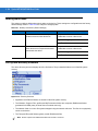
Customizing the Startup Program .................................................................................
Customizing the Home Screen View ............................................................................
Navigator.xml File Content ......................................................................................
Customizing the Scan Item or Scan Inventory Program ...............................................
Disabling MT2000 Scanner Services ............................................................................
7-1
7-2
7-3
7-4
7-5
7-6
Chapter 8: RS-232 Interface
Introduction ...................................................................................................................
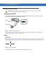
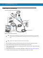
Connecting an RS-232 Interface ..................................................................................
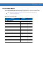
RS-232 Parameter Defaults ..........................................................................................
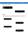
RS-232 Host Parameters ..............................................................................................
RS-232 Host Types .................................................................................................
Baud Rate ...............................................................................................................
Parity .......................................................................................................................
Stop Bit Select ........................................................................................................
Data Bits .................................................................................................................
Check Receive Errors .............................................................................................
Hardware Handshaking ..........................................................................................
Software Handshaking ............................................................................................
Host Serial Response Time-out ..............................................................................
RTS Line State ........................................................................................................
Beep on <BEL> .......................................................................................................
Intercharacter Delay ................................................................................................
Nixdorf Beep/LED Options ......................................................................................
Ignore Unknown Characters ...................................................................................
ASCII Character Set for RS-232 ...................................................................................
8-1
8-2
8-3
8-4
8-6
8-7
8-9
8-10
8-10
8-11
8-11
8-13
8-15
8-16
8-16
8-17
8-18
8-18
8-19
Chapter 9: USB Interface
Introduction ...................................................................................................................
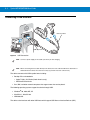
Connecting a USB Interface .........................................................................................
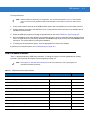
USB Parameter Defaults ..............................................................................................
USB Host Parameters ..................................................................................................
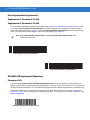
USB Device Type ....................................................................................................
CDC COM Port Emulation ......................................................................................
Symbol Native API (SNAPI) Status Handshaking ...................................................
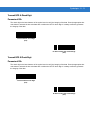
USB Country Keyboard Types - Country Codes .....................................................
USB Keystroke Delay .............................................................................................
USB CAPS Lock Override ......................................................................................
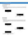
USB Ignore Unknown Characters ...........................................................................
Emulate Keypad ......................................................................................................
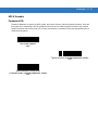
Emulate Keypad with Leading Zero ........................................................................
USB Keyboard FN 1 Substitution ............................................................................
Function Key Mapping ............................................................................................
Simulated Caps Lock ..............................................................................................
Convert Case ..........................................................................................................
ASCII Character Set for USB ........................................................................................
9-1
9-2
9-3
9-5
9-5
9-7
9-7
9-8
9-10
9-10
9-11
9-11
9-12
9-12
9-13
9-13
9-14
9-15
xiii
xiv
Symbol MT2070/MT2090 User Guide
Chapter 10: IBM 468X / 469X Interface
Introduction ...................................................................................................................
Connecting to an IBM 468X/469X Host ........................................................................
IBM Parameter Defaults ...............................................................................................
IBM 468X/469X Host Parameters .................................................................................
Port Address ...........................................................................................................
Convert Unknown to Code 39 .................................................................................
10-1
10-2
10-3
10-4
10-4
10-5
Chapter 11: Keyboard Wedge Interface
Introduction ...................................................................................................................
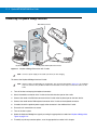
Connecting a Keyboard Wedge Interface .....................................................................
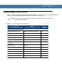
Keyboard Wedge Parameter Defaults ..........................................................................
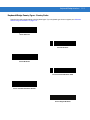
Keyboard Wedge Host Parameters ..............................................................................
Keyboard Wedge Host Types .................................................................................
Keyboard Wedge Country Types - Country Codes .................................................
Ignore Unknown Characters ...................................................................................
Keystroke Delay ......................................................................................................
Intra-Keystroke Delay .............................................................................................
Alternate Numeric Keypad Emulation .....................................................................
Caps Lock On .........................................................................................................
Caps Lock Override ................................................................................................
Convert Wedge Data ..............................................................................................
Function Key Mapping ............................................................................................
FN1 Substitution .....................................................................................................
Send Make and Break ............................................................................................
Keyboard Maps .......................................................................................................
ASCII Character Set for Keyboard Wedge ...................................................................
11-1
11-2
11-3
11-4
11-4
11-5
11-7
11-7
11-8
11-8
11-9
11-9
11-10
11-10
11-11
11-11
11-12
11-13
Chapter 12: Symbologies
Introduction ...................................................................................................................
Scanning Sequence Examples .....................................................................................
Errors While Scanning ..................................................................................................
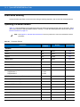
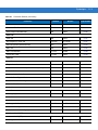
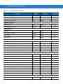
Symbology Parameter Defaults ....................................................................................
UPC/EAN ......................................................................................................................
Enable/Disable UPC-A ............................................................................................
Enable/Disable UPC-E ............................................................................................
Enable/Disable UPC-E1 ..........................................................................................
Enable/Disable EAN-8/JAN-8 .................................................................................
Enable/Disable EAN-13/JAN-13 .............................................................................
Enable/Disable Bookland EAN ...............................................................................
Decode UPC/EAN/JAN Supplementals ..................................................................
User-Programmable Supplementals .......................................................................
UPC/EAN/JAN Supplemental Redundancy ............................................................
Transmit UPC-A Check Digit ..................................................................................
Transmit UPC-E Check Digit ..................................................................................
Transmit UPC-E1 Check Digit ................................................................................
UPC-A Preamble ....................................................................................................
UPC-E Preamble ....................................................................................................
12-1
12-1
12-2
12-2
12-6
12-6
12-6
12-7
12-7
12-8
12-8
12-9
12-12
12-12
12-13
12-13
12-14
12-14
12-15
Table of Contents
UPC-E1 Preamble ..................................................................................................
Convert UPC-E to UPC-A .......................................................................................
Convert UPC-E1 to UPC-A .....................................................................................
EAN-8/JAN-8 Extend ..............................................................................................
Bookland ISBN Format ...........................................................................................
UCC Coupon Extended Code .................................................................................
Code 128 ......................................................................................................................
Enable/Disable Code 128 .......................................................................................
Set Lengths for Code 128 .......................................................................................
Enable/Disable GS1-128 (formerly UCC/EAN-128) ................................................
Enable/Disable ISBT 128 ........................................................................................
ISBT Concatenation ................................................................................................
Check ISBT Table ...................................................................................................
Code 39 ........................................................................................................................
Enable/Disable Code 39 .........................................................................................
Enable/Disable Trioptic Code 39 ............................................................................
Convert Code 39 to Code 32 ..................................................................................
Code 32 Prefix ........................................................................................................
Set Lengths for Code 39 .........................................................................................
Code 39 Check Digit Verification ............................................................................
Transmit Code 39 Check Digit ................................................................................
Code 39 Full ASCII Conversion ..............................................................................
Code 93 ........................................................................................................................
Enable/Disable Code 93 .........................................................................................
Set Lengths for Code 93 .........................................................................................
Code 11 ........................................................................................................................
Code 11 ..................................................................................................................
Set Lengths for Code 11 .........................................................................................
Code 11 Check Digit Verification ............................................................................
Transmit Code 11 Check Digits ..............................................................................
Interleaved 2 of 5 (ITF) .................................................................................................
Enable/Disable Interleaved 2 of 5 ...........................................................................
Set Lengths for Interleaved 2 of 5 ...........................................................................
I 2 of 5 Check Digit Verification ...............................................................................
Transmit I 2 of 5 Check Digit ...................................................................................
Convert I 2 of 5 to EAN-13 ......................................................................................
Discrete 2 of 5 (DTF) ....................................................................................................
Enable/Disable Discrete 2 of 5 ................................................................................
Set Lengths for Discrete 2 of 5 ...............................................................................
Codabar (NW - 7) .........................................................................................................
Enable/Disable Codabar .........................................................................................
Set Lengths for Codabar .........................................................................................
CLSI Editing ............................................................................................................
NOTIS Editing .........................................................................................................
MSI ...............................................................................................................................
Enable/Disable MSI ................................................................................................
Set Lengths for MSI ................................................................................................
MSI Check Digits ....................................................................................................
Transmit MSI Check Digit(s) ...................................................................................
MSI Check Digit Algorithm ......................................................................................
12-16
12-17
12-17
12-18
12-19
12-20
12-21
12-21
12-21
12-23
12-23
12-24
12-24
12-26
12-26
12-26
12-27
12-27
12-28
12-29
12-29
12-30
12-31
12-31
12-31
12-33
12-33
12-33
12-35
12-36
12-36
12-36
12-37
12-39
12-39
12-40
12-40
12-40
12-41
12-43
12-43
12-43
12-45
12-45
12-46
12-46
12-46
12-48
12-48
12-49
xv
xvi
Symbol MT2070/MT2090 User Guide
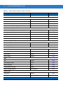
Postal Codes ................................................................................................................
US Postnet ..............................................................................................................
US Planet ................................................................................................................
Transmit US Postal Check Digit ..............................................................................
UK Postal ................................................................................................................
Transmit UK Postal Check Digit ..............................................................................
Japan Postal ...........................................................................................................
Australian Postal .....................................................................................................
Netherlands KIX Code ...........................................................................................
USPS 4CB/One Code/Intelligent Mail .....................................................................
UPU FICS Postal ....................................................................................................
GS1 DataBar ................................................................................................................
GS1 DataBar-14 .....................................................................................................
GS1 DataBar Limited ..............................................................................................
GS1 DataBar Expanded .........................................................................................
Convert GS1 DataBar to UPC/EAN ........................................................................
Composite .....................................................................................................................
Composite CC-C .....................................................................................................
Composite CC-A/B ..................................................................................................
Composite TLC-39 ..................................................................................................
UPC Composite Mode ............................................................................................
2D Symbologies ............................................................................................................
Enable/Disable PDF417 ..........................................................................................
Enable/Disable MicroPDF417 .................................................................................
Code 128 Emulation ...............................................................................................
Data Matrix ..............................................................................................................
Maxicode .................................................................................................................
QR Code .................................................................................................................
MicroQR ..................................................................................................................
Aztec .......................................................................................................................
Redundancy Level ........................................................................................................
Redundancy Level 1 ...............................................................................................
Redundancy Level 2 ...............................................................................................
Redundancy Level 3 ...............................................................................................
Redundancy Level 4 ...............................................................................................
Security Level ...............................................................................................................
Report Version ..............................................................................................................
Chapter 13: Accessories
Introduction ...................................................................................................................
Maintenance .................................................................................................................
Batteries ........................................................................................................................
Mounting .......................................................................................................................
Single Slot Cradles .......................................................................................................
Cradle Features ......................................................................................................
Battery Charging in the Cradle ................................................................................
Changing the Host Interface ...................................................................................
Communication .......................................................................................................
Sending Data to the Host Computer .................................................................
12-49
12-49
12-50
12-50
12-51
12-51
12-52
12-52
12-53
12-53
12-54
12-55
12-55
12-55
12-56
12-56
12-57
12-57
12-57
12-58
12-58
12-59
12-59
12-59
12-60
12-61
12-61
12-62
12-62
12-63
12-64
12-64
12-64
12-64
12-65
12-66
12-67
13-1
13-2
13-2
13-2
13-3
13-3
13-3
13-3
13-4
13-4
Table of Contents
LED Indicators ........................................................................................................
Miscellaneous LED Indicator Information .........................................................
Four Slot Cradles ..........................................................................................................
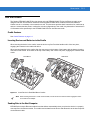
Cradle Features ......................................................................................................
Inserting Devices and Batteries in the Cradle .........................................................
Sending Data to the Host Computer .......................................................................
Charging .................................................................................................................
LED Indicators ........................................................................................................
Four Slot Battery Charger .............................................................................................
Features ..................................................................................................................
Inserting Batteries ...................................................................................................
Charging Batteries ..................................................................................................
LED Indicators ........................................................................................................
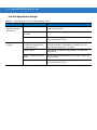
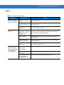
Troubleshooting ............................................................................................................
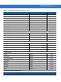
Chapter 14: Advanced Data Formatting
Introduction ...................................................................................................................
Rules: Criteria Linked to Actions ...................................................................................
Using ADF Bar Codes ..................................................................................................
ADF Bar Code Menu Example .....................................................................................
Rule 1: The Code 128 Scanning Rule ....................................................................
Rule 2: The UPC Scanning Rule ............................................................................
Alternate Rule Sets .................................................................................................
Rules Hierarchy (in Bar Codes) ..............................................................................
Default Rules ..........................................................................................................
ADF Bar Codes .............................................................................................................
Special Commands .......................................................................................................
Pause Duration .......................................................................................................
Begin New Rule ......................................................................................................
Save Rule ...............................................................................................................
Erase .......................................................................................................................
Quit Entering Rules .................................................................................................
Disable Rule Set .....................................................................................................
Criteria ..........................................................................................................................
Code Types .............................................................................................................
Code Lengths ..........................................................................................................
Message Containing A Specific Data String ...........................................................
Specific String at Start ......................................................................................
Specific String, Any Location ............................................................................
Any Message OK ..............................................................................................
Numeric Keypad ...............................................................................................
Rule Belongs To Set .........................................................................................
Actions ..........................................................................................................................
Send Data ...............................................................................................................
Setup Field(s) ..........................................................................................................
Move Cursor .....................................................................................................
Send Pause ......................................................................................................
Skip Ahead ........................................................................................................
Skip Back .........................................................................................................
13-4
13-4
13-5
13-5
13-5
13-5
13-6
13-6
13-7
13-7
13-7
13-7
13-8
13-9
14-1
14-1
14-2
14-2
14-3
14-3
14-3
14-4
14-5
14-5
14-7
14-7
14-7
14-7
14-8
14-8
14-9
14-10
14-10
14-17
14-21
14-21
14-22
14-22
14-23
14-25
14-26
14-26
14-29
14-30
14-30
14-31
14-32
xvii
xviii
Symbol MT2070/MT2090 User Guide
Send Preset Value ............................................................................................
Modify Data .............................................................................................................
Remove All Spaces ...........................................................................................
Crunch All Spaces ............................................................................................
Stop Space Removal ........................................................................................
Remove Leading Zeros .....................................................................................
Stop Zero Removal ...........................................................................................
Pad Data with Spaces .............................................................................................
Pad Data with Zeros ...............................................................................................
Beeps ......................................................................................................................
Send Keystroke (Control Characters and Keyboard Characters) ...........................
Control Characters ............................................................................................
Keyboard Characters ........................................................................................
Send ALT Characters .......................................................................................
Send Keypad Characters ..................................................................................
Send Function Key ............................................................................................
Send Right Control Key ..........................................................................................
Send Graphic User Interface (GUI) Characters ......................................................
Turn On/Off Rule Sets ............................................................................................
Alphanumeric Keyboard ...............................................................................................
14-34
14-35
14-35
14-35
14-35
14-35
14-35
14-36
14-40
14-45
14-45
14-45
14-50
14-64
14-69
14-74
14-81
14-82
14-87
14-89
Chapter 15: Maintenance and Troubleshooting
Introduction ...................................................................................................................
Maintenance .................................................................................................................
MT20X0 ..................................................................................................................
Battery .....................................................................................................................
Cradles ....................................................................................................................
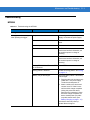
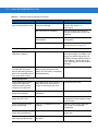
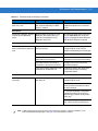
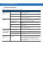
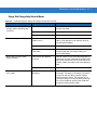
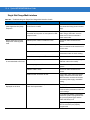
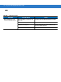
Troubleshooting ............................................................................................................
MT20X0 ..................................................................................................................
Single Slot Charge Only Cradle ..............................................................................
Single Slot Charge Only Vehicle Mount ..................................................................
Single Slot Charge Multi-interface ..........................................................................
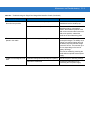
Four Slot Charge Only Ethernet ..............................................................................
Four Slot Charge Only Cradle .................................................................................
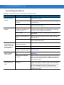
Four Slot Spare Battery Charger ............................................................................
Cables .....................................................................................................................
MCL ........................................................................................................................
15-1
15-1
15-1
15-2
15-2
15-3
15-3
15-6
15-7
15-8
15-10
15-11
15-12
15-13
15-14
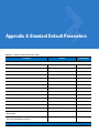
Appendix A: Standard Default Parameters
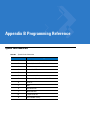
Appendix B: Programming Reference
Symbol Code Identifiers ................................................................................................ B-1
AIM Code Identifiers ..................................................................................................... B-2
Table of Contents
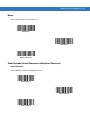
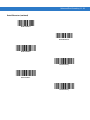
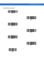
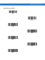
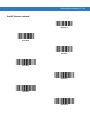
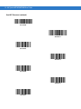
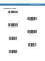
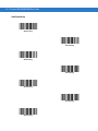
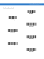
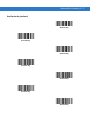
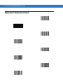
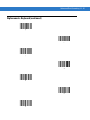
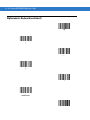
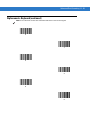
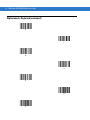
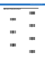
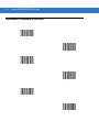
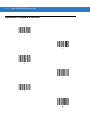
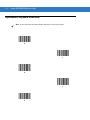
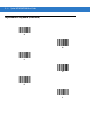
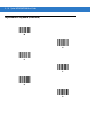
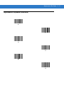
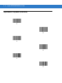
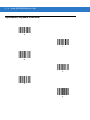
Appendix C: Sample Bar Codes
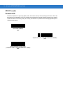
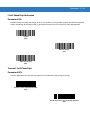
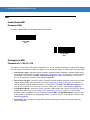
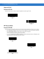
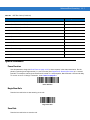
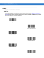
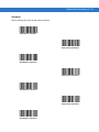
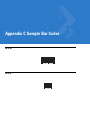
UPC-A ...........................................................................................................................
UPC-E ...........................................................................................................................
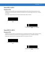
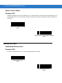
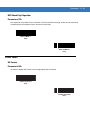
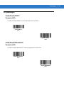
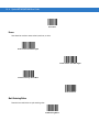
UPC-E1 .........................................................................................................................
EAN-13 .........................................................................................................................
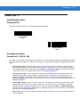
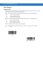
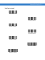
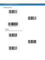
EAN-8 ...........................................................................................................................
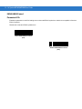
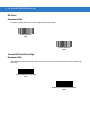
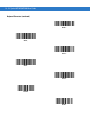
Code 39 ........................................................................................................................
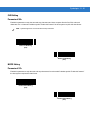
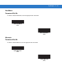
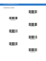
Trioptic Code 39 ...........................................................................................................
Code 93 ........................................................................................................................
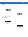
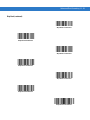
Code 11 ........................................................................................................................
Code 128 ......................................................................................................................
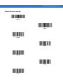
Codabar ........................................................................................................................
MSI ...............................................................................................................................
Interleaved 2 of 5 ..........................................................................................................
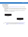
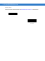
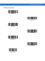
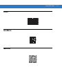
PDF417 .........................................................................................................................
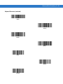
Data Matrix ...................................................................................................................
Maxicode ......................................................................................................................
QR Code .......................................................................................................................
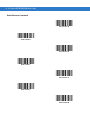
US Postnet ....................................................................................................................
UK Postal ......................................................................................................................
C-1
C-1
C-2
C-2
C-2
C-2
C-3
C-3
C-3
C-4
C-4
C-4
C-4
C-5
C-5
C-5
C-6
C-6
C-6
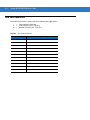
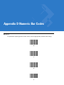
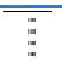
Appendix D: Numeric Bar Codes
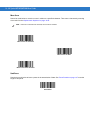
0, 1, 2, 3 ........................................................................................................................
4, 5, 6, 7 ........................................................................................................................
8, 9 ................................................................................................................................
Cancel ...........................................................................................................................
D-1
D-2
D-3
D-3
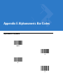
Appendix E: Alphanumeric Bar Codes
Alphanumeric Keyboard ............................................................................................... E-1
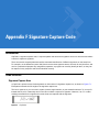
Appendix F: Signature Capture Code
Introduction ...................................................................................................................
Code Structure ..............................................................................................................
Signature Capture Area ..........................................................................................
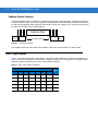
CapCode Pattern Structure .....................................................................................
Start / Stop Patterns .....................................................................................................
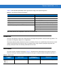
Dimensions ...................................................................................................................
Data Format ..................................................................................................................
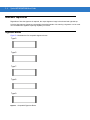
Additional Capabilities ..................................................................................................
Signature Boxes ...........................................................................................................
Index
Glossary
F-1
F-1
F-1
F-2
F-2
F-3
F-3
F-4
F-4
xix
xx
Symbol MT2070/MT2090 User Guide
About This Guide
Introduction
This guide provides information about using the Symbol MT2070/MT2090 devices.
NOTE
Screens and windows pictured in this guide are samples and can differ from actual screens.
Documentation Set
The documentation set for the Symbol MT2070/MT2090 devices provides information for specific user needs, and
includes:/
• MT2070/ MT2090 Quick Start Guide - describes how to get the device up and running (part number
72-117308-xx).
• MT2070/ MT2090 User Guide - describes how to use the device (part number 72E-117859-xx).
• MT2070/ MT2090 Integrator Guide - describes how to set up the device and accessories (72E-117858-xx).
• Enterprise Mobility Developer Kit (EMDK) Help File - provides API information for writing applications.
• MCL Technologies Start-up guide for the MT2000 - provides start up information for running MCL on an
MT20X0 device.
xx
Symbol MT2070/MT2090 User Guide
Device Configurations
Configuration
Radios
Display
Memory
Operating
System
Data Capture
Keypads
MT2090-SL0D6
2170WR
802.11/Bluetooth
320x240
Color
64 MB RAM
64 MB Flash
1D, Standard
Range, WW
Windows CE 5.0
21 key
MT2090-SD0D
62170WR
802.11/Bluetooth
320x240
Color
64 MB RAM
64 MB Flash
1D/2D, Standard
Range
Windows CE 5.0
21 key
MT2090-HD0D
62170WR
802.11/Bluetooth
320x240
Color
64 MB RAM
64 MB Flash
1D/2D, High
Definition
Windows CE 5.0
21 key
MT2090-DP0D
62170WR
802.11/Bluetooth
320x240
Color
64 MB RAM
64 MB Flash
DPM
Windows CE 5.0
21 key
MT2070-SL0D6
2370WR
Bluetooth
320x240
Color
64 MB RAM
64 MB Flash
1D, Standard
Range, MCL
Windows CE 5.0
21 key
MT2070-SD0D
62370WR
Bluetooth
320x240
Color
64 MB RAM
64 MB Flash
1D/2D,Standard
Range, MCL
Windows CE 5.0
21 key
MT2070-HD0D
62370WR
Bluetooth
320x240
Color
64 MB RAM
64 MB Flash
1D/2D, HD, MCL
Windows CE 5.0
21 key
MT2070-DP0D
62370WR
Bluetooth
320x240
Color
64 MB RAM
64 MB Flash
DPM, MCL
Windows CE 5.0
21 key
MT2070-SL1D6
2370WR
Bluetooth
320x240
Color
64 MB RAM
64 MB Flash
Standard Range,
EAS, MCL
Windows CE 5.0
21 key
MT2070-SD0D
62370WR
Bluetooth
320x240
Color
64 MB RAM
64 MB Flash
1D/2D, Standard
Range, EAS, MCL
Windows CE 5.0
21 key
Cradle Configurations
Cradle Configuration
Type
Radio
STB2000-C10007R
Single Slot, Charge Only with ActiveSync
N/A
STB2000-F10007R
Single Slot, Charge Only, Vehicle Mount
N/A
STB2078-C10007WR
Single Slot, Charge, Multi-interface
Bluetooth
STB2000-C40007R
Four Slot, Charge Only
N/A
STB2000-C40017R
Four Slot, Charge, Ethernet
N/A
SAC2000-4000CR Charger
Four Slot Spare Battery Charger
N/A
About This Guide
xxi
Chapter Descriptions
Topics covered in this guide are as follows:
• Chapter 1, Getting Started provides a product overview, unpacking instructions and start up information.
• Chapter 2, Operating the MT2070/MT2090 describes the device’s screens, and how to use the device.
• Chapter 3, Scanning describes parts of the device, beeper and LED definitions, and how to scan data.
• Chapter 4, Radio Communications provides information about the modes of operation and features available
for wireless communication between devices, cradles and hosts, and also includes the parameters
necessary to configure the device.
• Chapter 5, User Preferences & Miscellaneous Scanner Options describes each user preference feature and
provides the programming bar codes for selecting these features for the device. It also includes commonly
used bar codes to customize how data is transmitted to the host device.
• Chapter 6, Imaging Preferences describes each imager preference feature and provides the programming
bar codes for selecting these features for the device.
• Chapter 7, Customizing the MT20X0 provides information about customizing the MT20X0 device for the end
user.
• Chapter 8, RS-232 Interface provides information for setting up the device for RS-232 operation.
• Chapter 9, USB Interface provides information for setting up the device for USB operation.
• Chapter 10, IBM 468X / 469X Interface provides information for setting up the device with IBM 468X/469X
POS systems.
• Chapter 11, Keyboard Wedge Interface provides information for setting up the device for keyboard wedge
operation.
• Chapter 12, Symbologies describes all symbology features and provides the programming bar codes for
selecting these features.
• Chapter 13, Accessories describes all accessories for the device.
• Chapter 14, Advanced Data Formatting (ADF) describes how to customize scanned data before transmitting
to the host.
• Chapter 15, Maintenance and Troubleshooting provides information on how to care for the device and
troubleshooting the device and its cradles.
• Appendix A, Standard Default Parameters provides a table of all host devices and miscellaneous device
defaults.
• Appendix B, Programming Reference provides a table of AIM code identifiers, ASCII character conversions,
and keyboard maps.
• Appendix C, Sample Bar Codes includes sample bar codes.
• Appendix D, Numeric Bar Codes includes the numeric bar codes to scan for parameters requiring specific
numeric values.
• Appendix E, Alphanumeric Bar Codes includes the alphanumeric bar codes to scan for parameters requiring
alphanumeric values.
• Appendix F, Signature Capture Code provides information about using the device to capture a signature.
xxii
Symbol MT2070/MT2090 User Guide
Notational Conventions
The following conventions are used in this document:
• Italics are used to highlight the following:
• Chapters and sections in this and related documents
• Bold text is used to highlight the following:
• Key names on a keypad
• Button names on a screen or window.
• bullets (•) indicate:
• Action items
• Lists of alternatives
• Lists of required steps that are not necessarily sequential
• Sequential lists (e.g., those that describe step-by-step procedures) appear as numbered lists.
• Throughout the programming bar code menus, asterisks (*) are used to denote default parameter settings.
* Indicates Default
NOTE
*Baud Rate 9600
Feature/Option
This symbol indicates something of special interest or importance to the reader. Failure to read the note
will not result in physical harm to the reader, equipment or data.
CAUTION
WARNING!
This symbol indicates that if this information is ignored, the possibility of data or material damage may
occur.
This symbol indicates that if this information is ignored the possibility that serious personal
injury may occur.
About This Guide
xxiii
Related Documents
The following documents provide more information about the MT2070/MT2090 devices.
• MT2070/MT2090 Quick Start Guide (part number 72-117308-xx) - describes how to get the device up and
running.
• MT2070/MT2090 User Guide, part number 72E-117859-xx - describes how to use the device.
• MT2070/MT2090 Integrator Guide, part number 72E-117858-xx- describes how to set up the device and
accessories.
• Symbol STB2000/SAC2000 Cradles Quick Reference Guide (part number 72-117312-xx) - describes how to
install and operate the cradles.
For the latest version of this guide and all guides, go to: http://www.motorola.com/enterprisemobility/manuals.
Service Information
If you have a problem with your equipment, contact Motorola Enterprise Mobility Support for your region. Contact
information is available at: http:///www.motorola.com/enterprisemobility/contactsupport.
When contacting Enterprise Mobility Support, please have the following information available:
• Serial number of the device
• Device serial numbers are located on the label under the top of the device
• Cradles serial numbers are located on the label on the bottom of the cradle
• Model number or product name
• Device model numbers are located on the label under the top of the device
• Cradle model numbers are located on the label on the bottom of the cradle
• Software type and version number
• See Figure 2-10 on page 2-16.
Motorola responds to calls by E-mail, telephone or fax within the time limits set forth in support agreements.
If your problem cannot be solved by Motorola Enterprise Mobility Support, you may need to return your equipment
for servicing and will be given specific directions. Motorola is not responsible for any damages incurred during
shipment if the approved shipping container is not used. Shipping the units improperly can possibly void the
warranty.
If you purchased your Enterprise Mobility business product from a Motorola business partner, contact that business
partner for support.
xxiv
Symbol MT2070/MT2090 User Guide
Chapter 1 Getting Started
Introduction
This chapter lists the features of the device(s); accessories for the MT2000 Series devices; explains how to install
and charge the batteries; power the cradles; and, replace the lanyard (if purchased).
Unpacking
Carefully remove all protective material from around the equipment and inspect it for damage. If the equipment was
damaged in transit, contact Motorola Enterprise Mobility Support. See page xxiii for contact information. KEEP
THE PACKING. It is the approved shipping container and should be used if the equipment ever needs to be
returned for servicing.
MT20X0
Verify that the equipment listed below is included in the box:
• MT2070/MT2090
• Lithium-ion (Li-ion) battery
• Quick Start Guide.
Cradles
STB2000-C10007R Single Slot Charge Only with ActiveSync
Verify that the equipment listed below is included in the box:
• Cradle with desk mount cup installed
• Wall mount cup
• Regulatory Guide.
1-2
Symbol MT2070/MT2090 User Guide
STB2000-F10007R Forklift Single Slot Charge Only
Verify that the equipment listed below is included in the box:
• Cradle with forklift cup installed
• Metal mounting bracket with isolators
• Quick Reference Guide.
STB2078-C10007WR Single Slot Multi-interface Bluetooth
Verify that the equipment listed below is included in the box:
• Cradle with desk mount cup installed
• Wall mount cup
• Quick Reference Guide.
STB2000-C40007R Four Slot Charge Only
Verify that the equipment listed below is included in the box:
• Cradle with wall mount cups installed
• Quick Reference Guide.
STB2000-C40017R Four Slot Ethernet
Verify that the equipment listed below is included in the box:
• Cradle with wall mount cups installed
• Quick Reference Guide.
SAC2000-4000CR Four Slot Spare Battery Charger
Verify that the equipment listed below is included in the box:
• Charger
• Quick Reference Guide.
Accessories
See Chapter 13, Accessories for a list all accessories available for the MT2070/MT2090 devices.
Getting Started
Features
Scan LED
Display
Keypad
Scan LED
(MT2090 only)
Scan LED
(MT2090 only)
Scan
Window
* Accessory Port
Cover
Scan Trigger
Battery
Battery Latch
* Note: The accessory port is not available for use at this
time. The device is not water sealed if the accessory port
cover is removed.
Lanyard
Catch
Beeper
WARNING!
Hook Recesses for Wall Mount Cradle
Figure 1-1 MT2070/MT2090
Never connect an Ethernet or
phone cable to the host interface
port.
Charge/Communication Contacts
1-3
1-4
Symbol MT2070/MT2090 User Guide
Cradle Features
Single Slot - Front View and Connections
Horizontal
Desk
Mounting
Cup
Pairing Bar Code
(Bluetooth
cradles only)
Note: An
additional Pairing
Bar Code is
affixed under the
cup.
LED
Power
Connector
NOTE
USB/Host
Connector
The functionality of the USB connection to a host PC
varies by cradle type. For the single slot charge only
cradle, the USB connection can be used with a device in
the cradle for ActiveSync only. The charge only cradle
LED does not light when powered off USB only.
Latch
Charge/
Communication
Contacts
Figure 1-2 Single Slot Cradle - Connections/Pairing Bar Code
Getting Started
1-5
Single Slot - Back View
2
Mounting
Key-Hole
1
1
Forklift Bracket
Screw Hole
Rubber
Foot
Forklift Bracket
Screw Hole
Rubber Foot
Cable Ferrite Hook
Power
Cable
Groove
Cup
Release
Snaps
USB/Host
Cable
Groove
Host Port
Power Port
1Forklift
Bracket
Screw Hole
Desk Mount
Setting
Rubber Foot
Wall Mount
Setting
Wall Mount
Conversion Dial
2Mounting
Key-Hole
1
2
Used to fasten bracket to STB2000-F (forklift) cradle.
Used to mount STB20XX cradle.
Figure 1-3 Single Slot Cradle - Back
WARNING!
Never connect an
Ethernet or phone cable
to the host interface
port.
1-6
Symbol MT2070/MT2090 User Guide
Single Slot - Mounting Cups
Wall Mount Cup
Desk Mount Cup
Figure 1-4 Single Slot Cradle - Mounting Cups
Forklift Cup
Getting Started
Four Slot - Front View and Connections
Battery
Well
(four)
Battery
Charging
Contacts
Battery
Charging LED
(four)
Ethernet Activity
LEDs (Ethernet
Cradle cradles only)
Power
LED
Wall Mounting
Latches (two in
each well)
Figure 1-5 Four Slot Cradle - Front
Charging/
Communications
Contacts
Device Well
(four)
Interchangeable
Desk/Wall Mount
Cup (four)
1-7
1-8
Symbol MT2070/MT2090 User Guide
Four Slot - Back View
Mounting
Hole
Power Port
Primary Ethernet
Port (Ethernet
cradle only)
Secondary Ethernet
port for daisy chain
(Ethernet cradle only)
Mounting
Hole
Wall Mount Cup
Screws
Mounting Hole
Mounting
Hole
Wall Mount
Conversion
Dial
Cable Well
(2)
Figure 1-6 Four Slot Cradle - Back
NOTE
When daisy chaining Ethernet cradles: connect the first cradle in the daisy chain to the Ethernet hub via
the primary Ethernet port; connect the first cradle’s secondary port to the primary port of second cradle in
the chain; connect the second cradle’s secondary port to the primary port of third cradle in the chain; etc.
Each cradle in the daisy chain requires its own power supply.
Getting Started
1-9
Four Slot Spare Battery Charger
Battery
Charging
Contacts
Battery
Charging LED
(four)
Cradle
Power
LED
Battery
Well
(four)
Power Cable
Groove
Wall Mount
Key-Hole (4)
Cable Well
Rubber Feet
(4)
Power Port
Figure 1-7 Four Slot Spare Battery Charger
1 - 10 Symbol MT2070/MT2090 User Guide
Host Interfaces
This device supports the following host interfaces through communication with a single slot multi-interface cradle:
• Standard RS-232 connection to a host.
• Keyboard wedge connection to a host, where scanned data is interpreted as keystrokes. The following
international keyboards are supported (for Windows™ environment): North American, German, French,
French Belgian, French Canadian, Spanish, Italian, Swedish, UK English, Japanese, and Brazilian
Portuguese (see Keyboard Wedge Country Types - Country Codes on page 11-5 for a full list).
• IBM® 468X/469X hosts.
• USB connection to a host. The device autodetects a USB host and defaults to the HID keyboard interface
type. Select other USB interface types by scanning programming bar codes. The following international
keyboards are supported (for Windows™ environment): North America, German, French, French Belgian,
French Canadian, Spanish, Italian, Swedish, UK English, Japanese, and Brazilian Portuguese (see USB
Country Keyboard Types - Country Codes on page 9-8 for a full list).
NOTE
USB interface types can also be selected via the USB configuration menu on the device. To access the
USB configuration menu from the device’s Home screen, select Config... > Configure USB.
This device supports the following host interfaces without communication with a cradle:
• Standard RS-232 connection to a host.
• USB connection to a host via Bluetooth technology. The device autodetects a USB host and defaults to the
HID keyboard interface type. Select other USB interface types by scanning programming bar codes. The
following international keyboards are supported (for Windows™ environment): North America, German,
French, French Belgian, French Canadian, Spanish, Italian, Swedish, UK English, Japanese, and Brazilian
Portuguese.
NOTE
USB interface types can also be selected via the USB configuration menu on the device. To access the
USB configuration menu from the device’s Home screen, select Config... > Configure USB.
Out-of-Box Startup
To get the MT2070/MT2090 up and running:
• Insert the rechargeable Li-ion battery
• Connect power to the cradle.
• Insert the device in the cradle.
• Charge the device.
• Configure the device.
Getting Started 1 - 11
Insert the Battery
The battery resides in a chamber in the device handle.
NOTE
If the battery is completely discharged, and the unit is powered from a USB or RS232 cable, it may take up
to two hours for the unit to power up.There is no indication to the user of this condition and it may appear
that the unit is not charging and/or not working correctly. However, if the unit is placed in an STB2000
cradle with the 12V power supply power up is immediate.
To insert the battery:
1.
Insert the battery into the battery well, top first, ensuring that the battery connectors touch the device
connectors inside the well.
CAUTION
2.
Avoid touching the contacts when positioning the battery.
Push down on the back of the battery until it snaps into place.
Figure 1-8 Battery Insertion
Connect the Cradle
IMPORTANT Connect the interface cable and power supply (if necessary) in the following order to ensure proper
operation of the device and cradle.
Connecting the STB20XX Cradle
1.
Insert the host interface cable into the cradle's USB/host port. See Figure 1-2 on page 1-4 and Figure 1-5 on
page 1-7.
2.
Connect the other end of the host interface cable to the host.
3.
If necessary, connect the power supply to the cradle's power port (if the interface requires, or to allow fast
charging of the device).
4.
Connect the appropriate cable to the power supply and an AC power source, if necessary.
5.
If applicable, insert the power supply cable ferrite into the support features on the cradle bottom and run the
host and power cables into their respective cable grooves.
6.
For Bluetooth cradles only, pair the device to the cradle by scanning the pairing bar code on the cradle.
1 - 12 Symbol MT2070/MT2090 User Guide
7.
If necessary, scan the appropriate host bar code (for non-autodetected interfaces). See the specific host
chapter.
NOTE
Disconnect the power supply before changing host cables, or the device may not recognize the new host.
Different cables are required for different hosts. The connectors illustrated in each host chapter are
examples only. The connectors may be different from those illustrated, but the steps to connect the device
remain the same
Connecting STB2000-F Cradle
1.
Insert the host interface cable into the cradle's USB/host port. See Figure 1-2 on page 1-4.
2.
Connect the forklift power supply to the cradle's power port, if applicable.
3.
Optionally: Insert the power supply cable ferrite into the support features on the cradle bottom and run the host
and power cables into their respective cable grooves, or use cable ties to secure them to the mounting plate
after attaching it to the cradle. For more information about mounting options and procedures, refer to the
documentation included with the cradle.
4.
If necessary, scan the appropriate host bar code (for non-autodetected interfaces). See the specific host
chapter.
Changing the Host Interface
To connect to a different host, or to the same host using a different cable:
1.
Disconnect the power supply from the cradle, if used.
2.
Disconnect the interface cable from the host.
3.
Connect the interface cable to the new host, or the new interface cable to the existing host.
4.
Reconnect the power supply, if required.
5.
If necessary, scan the appropriate host bar code (for non-autodetected interfaces). See the specific host
chapter.
CAUTION
If the device does not recognize the host, disconnect the power supply, then reconnect after
connecting the host cable.
Supplying Power to the Cradle
The cradle receives power from one of two sources:
• An external power supply.
• When connected to the host through an interface cable that supplies power.
The cradle detects whether the host or the external supply is supplying power. It always draws power from the
external supply when available, regardless of the presence of power from a host.
Using the USB Interface to Supply Power
When the cradle is connected to the host via the USB interface, the USB port can power the cradle and an external
power supply is not necessary. Note that powering from a USB host charges the device at a slower rate than
charging from an external power supply. Additionally, depending on the level of activity, the device may not charge
at all.
Getting Started 1 - 13
Insert the Device in the Cradle
To insert the device in the cradle:
1.
Insert the device into the cradle top first.
2.
Push the handle until it clicks into place, engaging the contacts in the cradle and device.
1
1
2
1
2
2
Figure 1-9 Inserting the Device in the Single Slot Cradles
NOTE
When inserting the device in a wall mounted cradle, ensure the device’s hook recesses engage the hooks
on the wall mount adapter (when applicable).
Charge the Device Battery in the Cradle
For best performance, fully charge the device battery before using the device for the first time. To charge the
device battery, place the device in the cradle (see Insert the Device in the Cradle on page 1-13). The battery begins
charging when the device LED indicator starts flashing green. A complete charge of a fully discharged battery can
take up to four hours using external power and up to 10 hours using the interface cable.
Charge within the recommended temperature of 32° to 104° F (0° to 40° C) nominal, 41° to 95° F (5° to 35° C)
ideal.
For information on maximizing battery life, see Battery on page 15-2.
Charging Indicator/LED
The device has on screen charging indicators as well as an LED. The device’s flashing green LED indicates
charging activity (see Table 3-2 on page 3-3).
If the device displays ? or ? indicating a charging problem, remove the device from the cradle and replace
the battery. If one of these icons continues to display, contact Motorola Enterprise Mobility Support. See Screen
Icons on page 2-9 for descriptions of display icons.
Configure the Device
Use the bar codes in this manual to configure the device. See Chapter 5, User Preferences & Miscellaneous
Scanner Options, Chapter 6, Imaging Preferences and each host chapter for information about programming the
device using bar code menus.
1 - 14 Symbol MT2070/MT2090 User Guide
Battery Charging
IMPORTANT 1) If the host PC is powered off discharged, for example every night, the device continues to operate
from its battery until the battery is totally drained. Upon restart of the host PC, the device may not
boot. The battery has to charge at a reduced charge rate until the battery acquires sufficient charge
to boot the device. This can take up to 2 hours, depending on the level of discharge.
2) If the battery is completely discharged, and the unit is powered from a USB or RS232 cable, it
may take up to two hours for the unit to power up.There is no indication to the user of this condition
and it may appear that the unit is not charging and/or not working correctly. However, if the unit is
placed in an STB2000 or STB2078 cradle with the 12V power supply power up is immediate.
Charge the device using a cradle or host interface cable, or remove and charge the Li-ion battery using a spare
battery charger.
Before using the device for the first time, fully charge the Li-ion battery until the green LED on the device goes off
(seeTable 3-2 on page 3-3). The battery fully charges in less than four hours, when the device is placed in a cradle
with a 12V supply connected.
This device does not have a backup battery. Any data in RAM is lost when the battery is removed. However, the
real-time clock is maintained for a period of 20 minutes during a battery change.
Use the following accessories to charge the Li-ion battery:
• Cradles:
• Single Slot USB Charge Only Cradle - with power supply for fast charging
• Single Slot Multi-interface Bluetooth Cradle - with power supply; powered from host (slow charge)
• Four Slot Charge Only Cradle - with power supply
• Four Slot Ethernet Cradle - with power supply.
• Spare Battery Charger:
• Four Slot Battery Charger - with power supply.
• Cables (and a power supply):
• USB Client Charge Cable
• RS-232 Serial Cable - with power supply.
Use a cradle or a charge cable to charge the Li-ion battery in the device. Use either the four slot cradle or four slot
battery charger to charge up to four spare batteries. The charge cable requires a Symbol/Motorola approved power
supply.
• Cradles
Insert the device into a cradle. See Chapter 13, Accessories for accessory setup. The device starts to charge
automatically. The charge LED on the device flashes during charging and goes off when the battery is fully
charged. See Table 13-2 for charging indications.
• Cables
Connect a charge cable to the appropriate power source and connect the other end of the charge cable to
the device. See Chapter 13, Accessories for accessory setup. The device starts to charge automatically. The
charge LED on the device flashes during charging and goes off when the battery is fully charged. See Table
13-2 for charging indications.
See Table 3-2 on page 3-3 for detailed LED descriptions.
Getting Started 1 - 15
Battery Safety
IMPORTANT Battery safety depends on the proper selection and care of batteries.
Security Implementation/Protection From Counterfeit Batteries
Motorola devices are designed to work only with Motorola batteries. If you see a battery fault indication on the
device display, take the following steps:
• Remove the battery and inspect it to confirm that it bears the Motorola name and/or logo.
• If there is no Motorola name and/or logo, the battery is not a qualified battery.
• If there is a Motorola name and/or logo, replace the battery and retry charging it.
• If the message remains, contact a Motorola Enterprise Mobility service center.
Motorola Battery Safety Recommendations For Users
IMPORTANT Handle and store batteries properly to avoid injury or damage.
Most battery issues arise from improper handling of batteries and particularly from the continued use of damaged
batteries.
• Do not disassemble, crush, puncture, shred or otherwise attempt to change the form of the battery.
• Do not let the device or battery come in contact with water. Water can get into the circuits, leading to
corrosion. If the device and/or battery get wet, have them checked by your administrator or contact Motorola
even if they appear to be working properly.
• Do not allow the battery to touch metal objects. If metal objects stay in prolonged contact with the battery
contact points, the battery could become very hot.
• Do not place the battery near a heat source. Excessive heat can damage the device or the battery. High
temperatures can cause the battery to swell, leak or malfunction. Therefore:
• Do not dry a wet or damp battery with an appliance or heat source, such as a hair dryer or microwave
oven.
• Avoid leaving the device in areas of high temperatures.
• Do not drop the battery or device. Dropping these items, especially on a hard surface, can potentially cause
damage.
• Contact your service provider or Motorola if your device or battery was damaged from dropping or as a result
of exposure to high temperatures.
IMPORTANT Use only Motorola-branded batteries and chargers.
WARNING!
Use of a non-Motorola battery or charger may present a risk of fire, explosion, leakage or other
hazard.
1 - 16 Symbol MT2070/MT2090 User Guide
Proper and Safe Battery Disposal & Recycling:
Proper battery disposal is not only important for safety, it also benefits the environment. Promptly dispose of used
batteries in accordance with local regulations. Contact your local recycling center or national recycling
organizations for more information on how to dispose of batteries.
Additional information on proper disposal and recycling may be found on the Web at:
www.motorola.com/recycling and www.rbrc.org/call2recycle/.
Getting Started 1 - 17
Sending Data to the Host Computer
Out of the box, the device supports two modes to send data to a host computer: via cable (RS-232 or USB); and
via Bluetooth (open/paired with an STB2078 cradle).
Cable Mode
Via cable (RS-232 or USB) the user interface indicates the active mode for transmitting bar code data to the host.
• A
displays on the screen when bar code data transmits via USB.
• An
displays on the screen when bar code data transmits via RS-232.
Bluetooth Mode
In Bluetooth mode (open or cradle), a Bluetooth icon displays on the screen when bar code data transmits via
Bluetooth.
The cradle receives data from the device via a wireless radio connection and transmits it to the host computer via
the host cable. The device and cradle must be paired for successful wireless communication.
Pairing
Pairing registers a device to the cradle such that the device and cradle can exchange information. The cradles
operate in two modes: Point-to-Point and Multipoint-to-Point. In Point-to-Point mode, pair the device to the cradle
either by inserting it in the cradle (if pairing on insertion is enabled), or by scanning the pairing bar code. In
Multipoint-to-Point mode, you can pair up to seven devices to one cradle. To use this feature, scan the multipoint
bar code in Multipoint-to-Point Communication on page 4-19.
The cradle includes pairing bar codes on both its front and back. To pair the device with the cradle, scan a pairing
bar code. A high-low-high-low beep sequence followed by a low-high beep sequence indicates successful pairing
and connection to the remote device. A long low, long high beep sequence indicates unsuccessful pairing.
NOTE
The pairing bar code that connects the device to a cradle is unique to each cradle.
Do not scan data or parameters until pairing completes.
Lost Connection to Host
If scanned data does not transmit to the cradle's host, ensure that all cables are firmly inserted and the power
supply is connected to an appropriate AC outlet, if applicable. If scanned data still does not transmit to the host,
reestablish a connection with the host:
1.
Disconnect the power supply from the cradle.
2.
Disconnect the host interface cable from the cradle.
3.
Wait three seconds.
4.
Reconnect the host interface cable to the cradle.
5.
Reconnect the power supply to the cradle, if the host requires.
6.
Reestablish pairing with the cradle by scanning the pairing bar code.
1 - 18 Symbol MT2070/MT2090 User Guide
Radio Communications
The device can communicate with remote devices via Bluetooth Technology Profile Support, or by pairing with a
cradle. For radio communication parameters, detailed information about operational modes, Bluetooth Technology
Profile Support and pairing, see Chapter 4, Radio Communications.
Startup
When the device is powered on for the first time, it initializes. The splash screen appears for a short period of time.
If the device does not power on, see Resetting the Device on page 1-18.
MT2000
series
Figure 1-10 Splash Screen
Suspending/Powering Off the Device
A suspend menu item is accessible from Home screen. On the Home screen, press Menu > Suspend.
Resetting the Device
See Resetting the MT20X0 on page 2-97.
Turning the WLAN Radio On and Off
See Enable/Disable Radio on page 2-83.
Waking the Device
See Waking the MT20X0 on page 2-98.
Getting Started 1 - 19
Battery Removal
To remove the battery:
1.
Press Menu >Suspend to turn off the screen and place the device in suspend mode.
2.
With your thumb, press down on the indentation on the battery lock and drag it away from the battery.
3.
Lift up the back of the battery and pull it out of the battery well.
Battery lock
Figure 1-11 Li-ion Battery Removal
WARNING!
The device is not water sealed when the battery is removed.
Spare Battery Charging
Use the Spare Battery charger to charge spare Li-ion batteries. See to Chapter 13, Accessories for more
information on spare battery charging.
1 - 20 Symbol MT2070/MT2090 User Guide
Lanyard
To install the optional lanyard:
1.
Insert the loop on the lanyard into the slot at the bottom of the device.
Figure 1-12 Insert Lanyard Loop
2.
Thread the upper portion of the lanyard into the loop.
Figure 1-13 Thread the Loop
3.
Pull the clip through the loop over the tether point and tighten into place.
Figure 1-14 Insert Loop into Tether Point
Getting Started 1 - 21
Screen Protector
For added protection from scratches the device includes a protective film over the display window. It is
recommended you leave this on for added scratch resistance.
1 - 22 Symbol MT2070/MT2090 User Guide
Chapter 2 Operating the MT2070/MT2090
Introduction
This chapter provides instructions for using and navigating the device.
2-2
Symbol MT2070/MT2090 User Guide
Keypad
The keypad contains alphanumeric characters, scroll keys, function keys and an ENT (Enter) key. The keypad is
color-coded to indicate the alternate function keys (blue and orange). Note that an application can change the
keypad functions so the device's keypad may not function exactly as described. SeeTable 2-1 on page 2-3 for key
descriptions.
4-way Navigation
(Up, Down, Right, Left)
Right soft and CTRL key
ALT
CTRL
Backspace and ESC key
Left soft and
ALT key
Tab and * key
F
F
4 GHI
F
7 PQRS
Cold boot trigger
ESC
TAB
DEF
F
2
ABC
F
3
F
5
JKL
F
6 MNO
F
8
TUV
F
Orange key
0
9 WXVZ
ENT
Enter key
Blue key
Figure 2-1 MT2070/MT2090 Keypad
NOTE
The device does not have a Power key. To suspend the device go to Home screen; press the left soft key
(Menu); scroll to Suspend; press ENT.
Operating the MT2070/MT2090
2-3
Keypad Functionality
Table 2-1 Keypad Functionality
Key
Left Soft Key, ALT
Press Blue
Key
Description
Press Orange
Key
Defaults to the left soft key which initiates the action noted
on the bottom left of the screen (usually a menu option);
ALT key when the Blue function key is enabled.
ALT
N/A
Defaults to the right soft key which initiates the action
noted on the bottom right of the screen; CTRL key when
the Blue function key is enabled.
CTRL
N/A
Up, Down, Left, Right
Defaults to Scroll key allowing up, down, left, right
navigation.
N/A
N/A
Tab
Defaults to TAB key; asterisk (*) when the Blue function
key is enabled.
Depending on the screen display, TAB moves from pane
to pane in the contents section of a multipane display.
*
N/A
Defaults to backspace; ESC when the Blue function key is
enabled.
Depending on the screen display:
Returns to the previous level in the display.
Closes the menu and returns to the previous screen.
Clears a highlighted field.
ESC
N/A
Defaults to the number 1; F1 when the Blue function key
is enabled; characters . , - when the Orange function key
is enabled.
F1
.,-
Defaults to the number 2; F2 when the Blue function key
is enabled; A, B, C, a, b, c when the Orange function key
is enabled.
In alpha mode (enable Orange function key), the number
of key presses determines the letter and case.
1 key press = a
2 key presses = b
3 key presses = c
4 key presses = A
5 key presses = B
6 key presses = C
F2
a, b, c, A, B, C
ALT
Right Soft Key; CTRL
CTRL
TAB
Backspace, ESC
ESC
F1, 1, special characters
F
F2, 2, A, B, C, a, b, c
F
2
ABC
2-4
Symbol MT2070/MT2090 User Guide
Table 2-1 Keypad Functionality (Continued)
Key
F3, 3, D, E, F, d, e, f
F
3
DEF
F4, 4, G, H, I, g, h, i
F
4 GHI
F5, 5, J, K, L, j, k, l
F
5
JKL
Description
Press Blue
Key
Press Orange
Key
Defaults to the number 3; F3 when the Blue function key
is enabled; D, E, F, d, e, f when the Orange function key is
enabled.
In alpha mode (enable Orange function key), the number
of key presses determines the letter and
case.
1 key press = d
2 key presses = e
3 key presses = f
4 key presses = D
5 key presses = E
6 key presses = F
F3
d, e, f, D, E, F
Defaults to the number 4; F4 when the Blue function key
is enabled; G, H, I, g, h, i when the Orange function key is
enabled.
In alpha mode (enable Orange function key), the number
of key presses determines the letter and case.
1 key press = g
2 key presses = h
3 key presses = i
4 key presses = G
5 key presses = H
6 key presses = I
F4
g, h, i, G, H, I
Defaults to the number 5; F5 when the Blue function key
is enabled; J, K, L, j, k, l when the Orange function key is
enabled.
In alpha mode (enable Orange function key), the number
of key presses determines the letter and case.
1 key press = j
2 key presses = k
3 key presses = l
4 key presses = J
5 key presses = K
6 key presses = L
F5
j, k, l, J, K, L
Operating the MT2070/MT2090
2-5
Table 2-1 Keypad Functionality (Continued)
Key
F6, 6, M, N, 0, m, n, o
6 MNO
F
F7, 7, P, Q, R, S, p, q, r, s
F
7 PQRS
F8, 8, T, U, V, t, u, v
F
8
TUV
Description
Press Blue
Key
Press Orange
Key
Defaults to the number 6; F6 when the Blue function key
is enabled; M, N, 0, m, n, o when the Orange function key
is enabled.
In alpha mode (enable Orange function key), the number
of key presses determines the letter and case.
1 key press = m
2 key presses = n
3 key presses = o
4 key presses = M
5 key presses = N
6 key presses = O
F6
m, n, o, M, N, 0
Defaults to the number 7; F7 when the Blue function key
is enabled; P, Q, R, S, p, q, r, s when the Orange function
key is enabled.
In alpha mode (enable Orange function key), the number
of key presses determines the letter and case.
1 key press = p
2 key presses = q
3 key presses = r
3 key presses = s
4 key presses = P
5 key presses = Q
6 key presses = R
7 key presses = S
F7
p, q, r, s, P, Q,
R, S
Defaults to the number 8; F8 when the Blue function key
is enabled; T, U, V, t, u, v when the Orange function key is
enabled.
In alpha mode (enable Orange function key), the number
of key presses determines the letter and case.
1 key press = t
2 key presses = u
3 key presses = v
4 key presses = T
5 key presses = U
6 key presses = V
F8
t, u, v, T, U, V
2-6
Symbol MT2070/MT2090 User Guide
Table 2-1 Keypad Functionality (Continued)
Press Blue
Key
Press Orange
Key
Key
Description
F9, 9, W, X, Y, Z, w, x, y, z
Defaults to the number 9; F9 when the Blue function key
is enabled; W, X, Y, Z, w, x, y, z when the Orange function
key is enabled.
In alpha mode (enable Orange function key), the number
of key presses determines the letter and case.
1 key press = w
2 key presses = x
3 key presses = y
4 key presses = W
5 key presses = X
6 key presses = Y
F9
w, x, v, z, W, X,
V, Z
Defaults to the number 0; Displays the Home screen
when the Blue function key is enabled; space when the
Orange function key is enabled.
The Home key returns to the Home screen.
Home
Space
F
9 WXVZ
Home, 0, space
0
) can be used to:
]
The space (
• select/clear check boxes
• select an item.
Note: Under most
circumstances
pressing the
Home key brings
the Navigator
application to the
foreground.
However, Home
key functionality
depends upon the
current screen
display.
This key cannot
be programmed.
Operating the MT2070/MT2090
2-7
Table 2-1 Keypad Functionality (Continued)
Key
ENT
ENT
Description
Press ENT (Enter) to launch an application or select a
current/highlighted item.
Depending on the screen, press Enter to:
•
•
•
•
Orange
Press Blue
Key
Press Orange
Key
N/A
N/A
N/A
N/A
N/A
N/A
close a display and return to the previous screen.
lock in an entered quantity and highlight an item field.
store data from an item field.
to edit a highlighted item.
Press this key once to enable the orange alpha and
special character keys. Press the key again to disable
alpha and special character keys and return to default key
use.
When enabled, a filled orange circle
displays (see
Screen Icons on page 2-9). When no circle displays,
orange key functionality is disabled.
Blue
Press this key once to enable functionality of ALT, CTRL,
*, ESC or a function key. When enabled, an empty blue
circle
displays (see Screen Icons on page 2-9).
When no circle displays, blue key functionality is disabled.
2-8
Symbol MT2070/MT2090 User Guide
Using the Keypad to Navigate Applications
The screen is a non-touch screen. Navigation and control of an application is performed using the keypad.
Entering Information
To enter information:
• Use the keypad.
• Scan bar code data into data fields.
• Use Microsoft® ActiveSync® to synchronize or copy information from the host computer to the device. For
more information on ActiveSync, refer to the MT2070/MT2090 Integrator Guide (part number
72E-117858-xx).
Entering Information Using the Keypad
The alphanumeric keypads produce the 26-character alphabet (A-Z), numbers (0-9), function keys and assorted
characters. The keypads’ default characters/functions are printed white, the alpha character/functions are printed
orange and the function character/functions are printed blue. SeeKeypad on page 2-2 for keypad configurations.
Operating the MT2070/MT2090
Screen Icons
Table 2-2 Icons
Icon
Description
Battery
Critical low battery (< 5% full); recharge.
Battery fault.
Battery fault; AC power applied. Low battery; recharge.
Low battery; recharge.
Battery is 25% full.
Battery is 50% full.
Battery is 75% full.
Battery is fully charged.
Low battery; charging using AC power source.
Battery 25% full; charging using AC power source.
Battery 50% full; charging using AC power source.
Battery 75% full; charging using AC power source.
Battery is fully charged; AC power source connected.
2-9
2 - 10 Symbol MT2070/MT2090 User Guide
Table 2-2 Icons (Continued)
Icon
Description
Connections
Bluetooth is inactive (STB2078 cradle only).
Bluetooth is active (STB2078 cradle only).
RS-232 connection is active.
USB connection is active.
Keypad Functionality
One time blue key functionality (see Blue on page 2-7).
Unlimited orange key functionality (see Orange on page 2-7).
Wireless Signals (MT2090 Only)
No wireless signal or not associated.
Very low signal.
Low signal. Medium signal.
Medium signal.
Good signal.
Excellent signal.
Operating the MT2070/MT2090 2 - 11
Home Screen
When the device powers on, the first screen to display is the Home screen. This screen also launches when you
press the Home key (see Home, 0, space on page 2-6).
MT2070
MT2090
Figure 2-2 Home Screen
Table 2-3 lists the options available on the Home screen. Use the Up or Down Scroll key to highlight an option in
the list and press ENT to launch the screen.
Table 2-3 Home Screen Options
Option
Description
Scan Item
On this screen the user can, scan, display and transmit bar code data. See page 2-17.
Scan Inventory
On this screen the user can enter inventory information and send it to a local file in the Windows
CE file system. See page 2-20.
MCL (MT2070 Only)
The MCL application on the device is a simple scanning application which performs scanning
and sending bar codes to a host computer. See page 2-26.
Image Viewer
On this screen the user can preview, snap and save images. See page 2-30.
2 - 12 Symbol MT2070/MT2090 User Guide
Table 2-3 Home Screen Options (Continued)
Option
Config...
Description
On this screen the user has access to the following features:
• Wireless Companion - see page 2-32.
• Settings - see page 2-84.
• Rapid Deployment - see page 2-84.
• MSP Agent - see page 2-85.
• BTExplorer - see page 2-86.
• Configure USB - see page 2-93.
Utilities...
On this screen the user has access to the following features:
• File Explorer
• Task Manager.
See page 2-95.
Menu
This menu provides access to User Settings, Device Status, Battery Status and an About
screen. See page 2-13.
Menu
The Home screen Menu provides access to User Settings, Device Status, Battery Status and an About screen.
Press the Up or Down Scroll key to select an option. Press ENT to display the appropriate screen.
Figure 2-3 Home Screen Menu
Operating the MT2070/MT2090 2 - 13
User Settings
On this screen, make adjustments for the device’s beeper, backlight and time. Press the Up or Down Scroll key to
select an option.
Figure 2-4 User Settings Screen
• Beeper Volume: Scroll to Beeper Volume and press the right or left Scroll key to choose a Low, Medium or
High beeper volume. Press the right soft key (Done) to save changes and end the session.
• Beeper Frequency: Scroll to Beeper Frequency and press the right or left Scroll key to choose a Low,
Medium or High beeper frequency. Press the right soft key (Done) to save changes and end the session.
• Backlight: Scroll to Backlight and press ENT to display the Backlight screen.
Figure 2-5 Backlight Screen
Scroll to the appropriate line.
• Brightness: Use the right or left Scroll key to choose a brightness level for the display.
• Battery Timeout: Using the keypad, enter a numeric value to set the seconds in which the backlight turns off
when the device is exclusively using battery power.
• AC Timeout: Using the keypad, enter a numeric value to set the seconds in which the backlight turns off
when the device is not powered exclusively by battery power.
• Press the right soft key (Done) to save changes and end the session.
2 - 14 Symbol MT2070/MT2090 User Guide
• Date and Time: With Date and Time highlighted, press ENT to display the Date and Time screen.
Figure 2-6 Date and Time Screen
• Press TAB to toggle between Date: and Time: fields.
• Press the right or left Scroll key to move to sub-fields within Date: and Time:.
• Press the Up or Down Scroll key to change values.
Press the right soft key (OK) to save changes and end the session.
Press the left soft key (Cancel) to end the session without saving changes.
• Time Zone: With Time Zone highlighted, press ENT to display the Time Zone screen.
Figure 2-7 Time Zone Screen
• Press TAB to toggle between Time Zone: and Auto adjust fields.
• Press the Up or Down Scroll key to change the time zone.
• Press the Space key (see Space key on page 2-6) to check/uncheck the Auto adjust box. Press the right soft
key (OK) to save changes and end the session.
Press the left soft key (Cancel) to end the session without saving changes.
Operating the MT2070/MT2090 2 - 15
Device Status
This screen displays model, serial number, bluetooth and MAC address information about the device.
Figure 2-8 Device Status Screen
NOTE
MAC: field applies to the MT2090 only.
Battery Status
This screen displays the device’s battery information.
Figure 2-9 Battery Status Screen
2 - 16 Symbol MT2070/MT2090 User Guide
About
This screen displays version and copyright information.
Figure 2-10 About Screen
Suspend
On the Home screen (see Figure 2-2 on page 2-11) press Menu > Suspend to place the device in sleep mode. To
wake the device, press any key.
Operating the MT2070/MT2090 2 - 17
Scan Item
The Scan Item screen allows the user to transmit bar code data to the host PC. To access Scan Item, start at the
Home screen, scroll to Scan Item and press ENT.
Figure 2-11 Scan Item Screen
The following options are available:
• Scan a bar code. The data displays briefly in the Item: field and the bar code data transmits to the host PC
(Quantity defaults to a value of one and transmits one bar code.)
• Key an SKU or bar code data manually using the keyboard. Press ENT to transmit the data to the host PC.
(Quantity defaults to a value of one and transmits one SKU or bar code.)
• Press the up Scroll key to access the Quantity field; enter a quantity using the keyboard. Scan a bar code (or
enter an SKU/bar code manually and press ENT). The data transmits x times, where x = the quantity entered,
with a programmable delay between each transmit.
• Select Menu > Options... to set the transmit format (see Menu on page 2-18).
Quantity
Enter the quantity of SKUs or bar code data to transmit to the host PC (0 to 99999). Quantity defaults to a value of
one and transmits one bar code.
Item
The Item: field is highlighted by default. Scan a bar code or use the numeric keys to manually enter an SKU or bar
code. The default symbology type is Code 128.
2 - 18 Symbol MT2070/MT2090 User Guide
Menu
Press the left soft key to display the Menu.
Figure 2-12 Scan Item Screen - Menu
Options
Scroll to Options... and press ENT to display the options screen to set transmit bar code data options.
Transmit: Separate
Transmit: Together
Figure 2-13 Scan Item Screen - Menu - Options
• Transmit:
When you enter a quantity of two or more on the Scan Item screen, scroll to Transmit: in this
display and press the left or right scroll key to select how to transmit bar code data - Together or
Separate.
• Delimiter:
When you select to transmit bar code data Together, the Delimiter: field displays. Scroll to this
field and press the left or right scroll key to choose a delimiter method - comma, semi-colon or
tab.
• Delay:
When you select to transmit Separate bar code data, scroll to Delay: and enter the time in
milliseconds to separate the transmission of data.
• Barcode:
Scroll to Barcode: to choose a symbology type - Code 128 or Code 39.
• Clear Delay:The number of seconds a bar code clears after transmission.
• Cancel:
Press to cancel settings and return to previous screen.
• Done:
Press to save settings and return to previous screen.
Operating the MT2070/MT2090 2 - 19
About...
Displays information about the ScanItem application.
Close
Press the right soft key to close the screen and return Home.
Close
Scroll to Close and press ENT to exit and return Home.
2 - 20 Symbol MT2070/MT2090 User Guide
Scan Inventory
The Scan Inventory screen allows the user to enter inventory information and send it to a local file in the Windows
CE file system. Set the file type in which to save the inventory data in Menu > Options screen > Format: (see
Figure 2-16 on page 2-21).
To access Scan Inventory, start at the Home screen, scroll to Scan Inventory and press ENT.
Figure 2-14 Scan Inventory Screen - Default View
When the Scan Inventory screen displays for the first time, the cursor defaults to the Quantity field. If a quantity is
required, it must be enter prior to scanning or entering data in the Item field. Use the Up or Down Scroll key to
move from one field to another. Enter data as necessary.
Location
Use the keypad to enter a location. Location is an eight character alphanumeric field. Press the orange key to
enable the alpha keypad; press the orange key again to enable the numeric keypad. When the alpha keypad is
enabled and orange circle appears on the bottom of the screen.
Figure 2-15 Scan Inventory Screen - Location
The device remembers the location entered throughout the session, until it is changed and stores as the default
location in location.xml.
Operating the MT2070/MT2090 2 - 21
Quantity
Quantity defaults to a value of one to transmit one bar code to the host PC.
Scroll to Quantity and use the keypad to enter the quantity of SKUs or bar code data to transmit to the host PC (0
to 99999).
IMPORTANT Quantity must be entered prior to scanning or entering data in the Item field.
Item
Scroll to Item and scan a bar code or use the keypad to enter an SKU or bar code to transmit to the host PC. The
data displays on the screen for 3 seconds or less with a trigger or key press. The default symbology type is Code
128.
Menu
Press the left soft key to display the Menu.
Figure 2-16 Scan Inventory Screen - Menu
View Inventory
Scroll to View Inventory and press ENT to display a list of the saved inventory items stored in the device. Each row
in the list includes location, quantity and bar code/SKU.
The current inventory stores in a .txt or .xml file located in the Applications/Inventory folder. If no inventory items
were saved, the file does not exist and no contents display. If the file does exist, the items display in a list view with
column headers for location, item and quantity.
The View Inventory screen has several menu options for maintaining information saved in the inventory file.
2 - 22 Symbol MT2070/MT2090 User Guide
View Inventory Menu
The View Inventory menu includes several options to maintain and customize inventory data. On the View
Inventory screen press the left soft key to display the menu items. Press the Up or Down Scroll key to select an
option. Press ENT to display the appropriate screen.
Figure 2-17 View Inventory Menu
• Edit
Ensure the item to edit is highlighted on the View Inventory screen, then press Menu > Edit. On the Edit Item
screen (Figure 2-18) edit the inventory data as needed (scanning is disabled in this view and data must be
edited manually). Press TAB to move from field to field. Use the keypad to edit the information in each field.
NOTE
By default the orange key is not active in the Edit Item window. If necessary, press the orange key to
enable/disable the alpha key pad.
Press the left soft key (Cancel) to cancel the edits and return to the View Inventory screen. Press the right
soft key (OK) to save the edits.
Figure 2-18 Edit Item Screen
Operating the MT2070/MT2090 2 - 23
• Delete Item
Ensure the item to delete is highlighted on the View Inventory screen, then press Menu > Delete Item... . The
following confirmation dialog displays. Press the left soft key (No) to cancel the delete and return to the View
Inventory screen. Press the right soft key (Yes) to delete the selected inventory item.
Figure 2-19 Delete Item Dialog
• Delete All
On the View Inventory screen, press Menu > Delete All... . The following confirmation dialog displays. Press
the left soft key (No) to cancel the delete and return to the View Inventory screen. Press the right soft key
(Yes) to delete all inventory items listed.
Figure 2-20 Delete All Dialog
• Transmit
Selecting Transmit sends data to the host PC via the configured interface and protocol (such as USB HID
keyboard).
On the View Inventory screen, press Menu > Transmit to send data.
NOTE
Data is not deleted after transmission.
2 - 24 Symbol MT2070/MT2090 User Guide
• Export
Exporting formats data in a user friendly layout which can be downloaded from the device. On the View
Inventory screen, press Menu > Export. The dialog in Figure 2-21 displays indicating the path of the file to be
exported to the Application folder on the device. The default file name and type is export.txt. Press ENT to
export all data and return to the View Inventory screen.
Figure 2-21 Export Dialog
NOTE
The export format, text or XML, is specified in Options... on page 2-25.
• Save
Saving data ensures that data is not lost during a warm or cold boot. For example, when the user inserts a
new battery in the device, a save is recommended prior to switching batteries. On the View Inventory screen,
press Menu > Save. The following dialog displays indicating a successful save. Press ENT to accept the
save and return to the View Inventory screen.
Figure 2-22 Save Dialog
• Options
On the View Inventory screen, press Menu > Options.
Save Inventory
Scroll to Save and press ENT to save the data to the location specified in the Options dialog.
Operating the MT2070/MT2090 2 - 25
Options...
Scroll to Options and press ENT to configure the inventory application. On this screen, set the file format and the
file storage location to save data. The format is specified in an xml file located in the folder \application\inventory.
Press the Up or Down Scroll key to move from field to field. Use the keypad to enter a value in the File: field; Press
the right or left Scroll key to change the data within all other fields.
Figure 2-23 Options Screen
• File:
Specify a file type.
• Format:
Specify a Text of XML file format.
• Separator: Specify a delimiter (comma, semi-colon or tab).
• Grouped:
Select No if data is exported/transmitted in the order scanned; select Yes if data is
exported/transmitted by group.
• Clear Delay:The time in seconds data is automatically cleared from the display after scanning.
• Cancel:
Press to cancel settings and return to previous screen.
• Done:
Press to save settings and return to previous screen.
About...
Displays information about the ScanInventory application.
Close
Scroll to Close and press ENT to exit and return Home.
2 - 26 Symbol MT2070/MT2090 User Guide
MCL
When you select MCL from the Home screen, the MCL-Client loads and the MCL program which loaded on the
device runs.
Figure 2-24 MCL-CIient Load - Typical View
By default, the MCL application on the device is a simple scanning application which performs scanning and
sending bar codes to a host computer, and scanning inventory with a timestamp.
NOTE
The MCL client is pre-licensed on the MT2070 only. The MCL client on the MT2090 requires an activated
license to run.
MCL-Collection is an intuitive, high-productivity software tool used to create, integrate and deploy enterprise,
multimodal mobile worker applications quickly and easily. From bar code scanning and data capture on devices to
ODBC, WMS, or SAP R/3 connectivity on the host, MCL-Collection provides seamless integration from the
computer to host application.
For more information refer to the MCL Technologies Start Up Guide for the MT2000 at:
http://www.mcl-collection.com.
When the MCL-Client loads, the Main Menu screen of the default MCL program loads. On this screen, select the
mode (Scan Transmit on page 2-27 or Scan Inventory on page 2-28) of the MCL default scanning application.
Figure 2-25 MT2000 Default Application Home Screen - Typical View
Operating the MT2070/MT2090 2 - 27
Scan Transmit
When Scan Transmit is selected on the Main Menu, the Scan & Send screen displays. On this screen the user can
manually enter a quantity and scan data to a computer using a tethered cable or a Bluetooth connection via the
STB2078 cradle.
Figure 2-26 Scan & Send Screen
•
: Use the keypad to enter a quantity into this field. Scanning is disabled when this field is highlighted.
•
: Scan a bar code to enter data into this field. After scanning data, the quantity and data are sent to
MCL Link.
NOTE
On the first transmit; the application establishes communication with MCL link which may take several
seconds.
2 - 28 Symbol MT2070/MT2090 User Guide
Scan Inventory
When Scan Inventory is selected on the Main Menu, the Scan Inventory screen displays (Figure 2-27). On this
screen the user must enter the location in which the inventory is scanned. When a location is not entered, two short
beeps sound indicating an error.
1.
Use the keypad to enter a location and press ENT to continue.
Figure 2-27 Scan Inventory Screen
2.
Upon pressing ENT, the Scan screen displays.
Figure 2-28 Scan Inventory Scan Screen
3.
: Use the keypad to enter a quantity into this field. Scanning is disabled when this field is highlighted.
4.
: Scan a bar code to enter data into this field. Scanned data in this screen is stored on the FFS file
system and can be viewed, deleted, or transmitted to MCL Link.
Operating the MT2070/MT2090 2 - 29
5.
Use the right soft key to select MENU. The Inventory Menu displays.
Figure 2-29 Inventory Menu Screen
6.
Select the appropriate option and press the right soft key (OK) to perform the appropriate action (View Data,
Send Data, Delete Last).
View Data
The View Data screen provides a list of all scanned data including the location, item, quantity, date and time. On
this screen, press the right soft key to display menu options to edit a selected record, delete a selected record or
delete all records.
Figure 2-30 View Data Screen
Send Data
Select this option to transmit scanned data to the host PC MCL Link application.
Delete Last
Select this option to delete the last item scanned.
2 - 30 Symbol MT2070/MT2090 User Guide
Image Viewer (Devices Equipped with Imagers)
The Image Viewer screen allows the user to preview, snap and save images.
To access Imager Sample, start at the Home screen, scroll to Imager Sample and press ENT
Figure 2-31 Image Viewer Screen
Menu
Press the left soft key to display the Menu.
Figure 2-32 Image Viewer Screen - Menu
Preview On
Scroll to Preview On and press ENT to display a preview of an image. Point the scan window at the image and
press the scan trigger to take a picture.
Open
Scroll to Open and press ENT to display the File Explorer. Press the Up or Down Scroll key to find an image and
press ENT to display it.
Operating the MT2070/MT2090 2 - 31
Options
Scroll to Options and press ENT to display the Options screen. Press the up or down Scroll key to select an option
to edit and press ENT.
Figure 2-33 Options Screen
• JPEG Quality: Picture quality indicator. Higher numbers produce better quality pictures and larger file sizes).
• Illumination:
Press the right and left scroll keys to turn illumination On or Off. The default is Off. Depending
on the room lighting, an image captured by the device may appear too dark. The illumination
feature allows you to adjust the lighting on the snapshot target.
• Preview Aim: Laser emits when the trigger is pulled.
About
Displays information about the Imager demo application.
Close
Press the right soft key to close the screen and return Home.
2 - 32 Symbol MT2070/MT2090 User Guide
Config
To access Config, start at the Home screen, scroll to Config... and press ENT.
MT2070
MT2090
Figure 2-34 Config... Screens
Wireless Companion (MT2090 Only)
NOTE
Some screens and windows pictured in this section are samples and can differ from actual screens.
The Wireless Companion is used to configure and manage the device’s wireless network settings. On the Config...
screen press the up or down Scroll key to highlight Wireless Companion and press ENT to display the Wireless
Companion menu.
Figure 2-35 Config... Wireless Companion Menu
Operating the MT2070/MT2090 2 - 33
Find WLANs
On the Wireless Companion menu, press the up or down Scroll key to highlight Find WLANs and press ENT to
display the Find WLANs screen.
Figure 2-36 Find WLANs Screen
The Find WLANs list displays:
• WLAN Networks:Available wireless networks.
• Network Type:
Type of network. 802.11(a), 802.11(b) or 802.11(g).
• Channel:
Channel on which the AP is transmitting.
• Signal Strength: The signal strength of the signal from the AP.
Highlight a network in the list and press ENT to open a pop-up menu which provides two options:
Connect and Refresh. Select Refresh to refresh the WLAN list. Select Connect to create a WLAN profile from that
network (see Manage Profiles on page 2-33). This opens the Profile Entry screen which allows you to set the
values for the selected network. After editing the profile, the device automatically connects to this new profile.
Manage Profiles
The Manage Profiles screen provides a list of user-configured wireless profiles. Define up to 32 profiles at any one
time.
On the Wireless Companion menu, press the up or down Scroll key to highlight Manage Profiles and press ENT to
display the Manage Profiles screen.
Figure 2-37 Manage Profiles Screen
2 - 34 Symbol MT2070/MT2090 User Guide
Icons next to each profile identify the profiles current state.
Table 2-4 Profile Icons
Icon
No Icon
Description
Profile is not selected, but enabled.
Profile is disabled.
Profile is Cancelled. A Cancelled profile is disabled until a connect or login function is performed through
the configuration editor.
Profile is currently in use and describes an infrastructure profile not using encryption.
Profile is currently in use and describes an infrastructure profile using encryption.
Profile is currently in use and describes an ad-hoc profile not using encryption.
Profile is currently in use and describes an ad-hoc profile using encryption.
Profile is not valid in the device current operating regulatory domain.
The profiles are listed in priority order for use by the automatic roaming feature. Change the order by moving
profiles up or down. Edit existing profiles by selecting one in the list and then pressing ENT to display the menu.
The menu allows the selected profile to be connected, edited, disabled (enabled) or deleted. (Note: the Disable
menu item changes to Enable if the profile is already disabled.)
A dialog displays to confirm the users desire to delete a profile, if selected.
Changing Profiles
A completed profile is a set of configuration settings that can be used in different locations to connect to a wireless
network. Create different profiles to have pre-defined operating parameters available for use in various network
environments. When the Manage Profiles screen displays, existing profiles appear in the list.
To change an existing profile, highlight a profile on the Manage Profiles screen, press ENT to display the menu,
scroll to Edit and press ENT.
Creating a New Profile
Creating a new profile allows the user to configure profile name, ESSID, security, network address information and
the power consumption level.
Operating the MT2070/MT2090 2 - 35
Profile ID
Press the up or down Scroll key on the profile menu and select Add. The Profile Entry dialog displays.
Figure 2-38 Profile Entry Screen
Profile Name
The name and (WLAN) identifier of the network connection. Enter a user friendly name for the device profile used
to connect to either an AP or another networked device. Example: The Public LAN.
NOTE
Two profiles with the same user friendly name are acceptable but not recommended.
ESSID
The ESSID is the 802.11 extended service set identifier. The ESSID is 32-character (maximum) case sensitive
string identifying the WLAN and must match the AP ESSID for the device to communicate with the AP.
Tab to Next > and press ENT to move to the Operating Mode dialog.
Operating Mode
Figure 2-39 2-33
Operating Mode/Country Screen
2 - 36 Symbol MT2070/MT2090 User Guide
Operating Mode
Select the operating mode (Infrastructure or Ad-Hoc) from the Operating Mode: drop-down list. The operating
mode Infrastructure enables the device to transmit and receive data with an AP. Infrastructure is the default mode.
Table 2-5 Operating Mode Fields
Field
Description
Operating Mode
Infrastructure: Select Infrastructure to enable the device to transmit and receive data with an AP.
Infrastructure is the device default mode.
Ad Hoc: Select Ad Hoc to enable the device to form its own local network where devices
communicate peer-to-peer without APs using a shared ESSID. If Ad-Hoc mode was selected,
see Channel on page 2-37. If Infrastructure mode was selected, see Security Mode on page
2-38
Country
Country: is used to determine if the profile is valid for the country of operation. The profile country
must match the country in the options. page or it must match the acquired country if 802.11d is
enabled.
Single Country Use:
When the device is only to be used in a single country, set every profile country to Allow Any
Country. In the Options > Regulatory dialog box (see Figure 2-86 on page 2-68), set the country to
the specific country the device is to be used in, and deselect (uncheck) the Enable 802.11d
option. This is the most common and the efficient configuration. It eliminates the initialization
overhead associated with acquiring a country via 802.11d.
Multiple Country Use:
When the device may be used in more than one country, select (check) the Enable 802.11d
option in the Regulatory Options dialog box (see Figure 2-86 on page 2-68). This eliminates the
need for reprogramming the country (in Options > Regulatory) each time a new country is entered.
However, this only works if the infrastructure (i.e. APs) support 802.11d (some infrastructures do
not support 802.11d, including some Cisco APs). When the Enable 802.11d option is selected,
the Options > Regulatory > Country setting is not used. For a single profile that can be used in
multiple countries, with infrastructure that supports 802.11d (including Symbol infrastructure), set
the Profile Country to Allow Any Country. Under Options > Regulatory, select Enable 802.11d. The
Options > Regulatory > Country setting is not used.
For a single profile that can be used in multiple countries, but with infrastructure that does not
support 802.11d, set the profile country to Allow Any Country, and de-select (uncheck) Enable
802.11d. In this case, the Options > Regulatory > Country setting must always be set to the country
the device is currently in. This configuration option is the most efficient and may be chosen for
use with any infrastructure. However, the Options > Regulatory > Country setting must be manually
changed when a new country is entered.
(continued)
Tab to Next > and press ENT to move to the next dialog.
Operating the MT2070/MT2090 2 - 37
Channel
If Ad-Hoc mode was selected the Ad-Hoc Channel dialog displays.
Figure 2-40 Ad-Hoc - Channel Screen
Use the Ad-Hoc Channel dialog to configure the required information to create an Ad-Hoc profile. This dialog does
not appear if you selected Infrastructure mode. Select a channel number from the Channel drop-down list.
NOTE
In the case of a country where DFS is implemented in band 5150-5250 MHz, Ad-hoc is not allowed and
the user needs to move and select a channel in the 2.4 GHz band.
NOTE
Ad-hoc channels are specific to the country selected.
Table 2-6
Ad-Hoc Channels
Band
2.4 GHz
Channel
Frequency
1
2412 MHz
2
2417 MHz
3
2422 MHz
4
2427 MHz
5
2432 MHz
6
2437 MHz
7
2442 MHz
8
2447 MHz
9
2452 MHz
10
2457 MHz
11
2462 MHz
2 - 38 Symbol MT2070/MT2090 User Guide
Security Mode
If Infrastructure mode was selected the Security Mode dialog displays.
Figure 2-41 Infrastructure - Security Mode/Authentication Type
Operating the MT2070/MT2090 2 - 39
Security Mode
Use the Security Mode dialog to configure the Security and Authentication methods. If Ad-Hoc mode is selected,
this dialog is not available and authentication is set to None by default.
Select the security mode from the Security Mode drop-down list. The selection chosen affects the availability of
other choices for Authentication Type and Encryption methods.
• LEGACY (Pre-WPA): This mode allows the user to configure protocols not available in the other Security
Mode selections: Open authentication / encryption; Open authentication with WEP 40
or WEP 128; and 802.1X authentications that use WEP128 Encryption.
• WPA-Personal:
This mode allows the user to configure a WPA-TKIP-PSK protocol.
• WPA2-Personal
This mode allows the user to configure WPA2-PSK protocols with the Advanced
Encryption Standard (AES) encryption method.
• WPA-Enterprise:
This mode allows the user to configure profiles with 802.1X Authentication that uses
WPA and TKIP encryption method.
• WPA2-Enterprise:
This mode allows the user to configure profiles with 802.1X Authentication that uses
WPA2 with AES encryption method.
Table 2-7 Security Modes
Authentication
Types
Encryption Types
Legacy (Pre-WPA)
None,
EAP-TLS,
EAP-FAST,
PEAP,
LEAP,
TTLS
Open,
WEP-40 (40/24),
WEP-104 (104/24),
TKIP,
AES
Enabled. User input required with pass-phrase/hex key
configuration.
WPA - Personal
None
TKIP
Enabled. User input required with pass-phrase/hex key
configuration.
WPA2 - Personal
None
AES
Enabled. User input required with pass-phrase/hex key
configuration.
WPA - Enterprise
EAP-TLS,
EAP-FAST,
PEAP,
LEAP,
TTLS
TKIP
Disabled. No user input required for encryption key.
WPA2 - Enterprise
EAP-TLS,
EAP-FAST,
PEAP,
LEAP,
TTLS
AES
Disabled. No user input required for encryption key.
Security Mode
Pass-phrase/Hexkey Configuration
2 - 40 Symbol MT2070/MT2090 User Guide
Authentication Type
Select an available authentication type from the drop-down list. The options listed in the drop-down list are based
on the selected Security Mode as shown in Table 2-8.
The authentication types, other than None, all use IEEE 802.1x authentication to ensure that only valid users and
sometimes servers can connect to the network. Each authentication type uses a different scheme using various
combinations of tunnels, username/passwords, user certificates, server certificates and Protected Access
Credentials (PACs).
Table 2-8
Authentication Options
Authentication
Description
None
Use this setting when authentication is not required on the network.
EAP-TLS
Select this option to enable EAP-TLS authentication. A user certificate is required; validating the
server certificate is optional.
EAP-FAST
Select this option to enable EAP-FAST authentication. This type uses a PAC (Protected Access
Credential) to establish a tunnel and then uses the selected tunnel type to verify credentials.
PACs are handled behind the scenes, transparently to the user. Automatic PAC provisioning can,
depending on the tunnel type, require a user certificate and the validation of a server certificate.
Manual PAC provisioning is currently not supported.
PEAP
Select this option to enable PEAP authentication. This type establishes a tunnel and then based
on the tunnel type, uses a user certificate and/or a username/password. Validating the server
certificate is optional.
LEAP
Select this option to enable LEAP authentication. This type does not establish a tunnel. It
requires a username and password.
TTLS
Select this option to enable TTLS authentication. This type establishes a tunnel and then based
on the tunnel type, uses a user certificate and/or a username/password. Validating the server
certificate is optional.
Tab to Next > and press ENT. Selecting PEAP, TTLS or EAP-FAST displays the Tunneled Authentication Type
dialog. Selecting None displays the Encryption dialog. Selecting EAP-TLS displays the Installed User Certs dialog.
Selecting LEAP displays the User Name dialog.
Tunneled Authentication
Use the Tunneled Authentication Type dialog to select the tunneled authentication options. The content of the
dialog differs depending on the Authentication Type chosen.
Figure 2-42 Tunneled Authentication Dialog Box
Operating the MT2070/MT2090 2 - 41
To select a tunneled authentication type:
1.
Select a tunneled authentication type from the drop-down list. See Table 2-9 for the Tunnel Authentication
options for each authentication type.
2.
Select the User Certificate check box if a certificate is required. If the TLS tunnel type that requires a user
certificate is selected, the check box is already selected.
3.
Tab to Next > and press ENT. The Installed User Certificates dialog displays.
Table 2-9 Tunneled Authentication Options
Authentication Type
Tunneled
Authentication
PEAP
CHAP
EAP-GTC
TTLS
EAP-FAST
X
X
Description
Challenge Handshake Authentication Protocol (CHAP) is one of the two
main authentication protocols used to verify the user name and
password for PPP Internet connections. CHAP is more secure than
PAP because it performs a three way handshake during the initial link
establishment between the home and remote machines. It can also
repeat the authentication anytime after the link is established.
X
EAP-GTC is used during phase 2 of the authentication process. This
method uses a time-synchronized hardware or software token
generator, often in conjunction with a user PIN, to create a one-time
password.
MD5
X
Message Digest-5 (MD5) is an authentication algorithm developed by
RSA. MD5 generates a 128-bit message digest using a 128-bit key,
IPSec truncates the message digest to 96 bits.
MS CHAP
X
Microsoft Challenge Handshake Authentication Protocol (MS CHAP) is
an implementation of the CHAP protocol that Microsoft created to
authenticate remote Windows workstations. MS CHAP is identical to
CHAP, except that MS CHAP is based on the encryption and hashing
algorithms used by Windows networks and the MS CHAP response to
a challenge is in a format optimized for compatibility with Windows
operating systems.
2 - 42 Symbol MT2070/MT2090 User Guide
Table 2-9 Tunneled Authentication Options (Continued)
Authentication Type
Tunneled
Authentication
MS CHAP v2
PEAP
TTLS
EAP-FAST
Description
X
X
X
Microsoft Challenge Handshake Authentication Protocol version 2 (MS
CHAP v2) is a password-based, challenge-response, mutual
authentication protocol that uses the industry-standard Message Digest
4 (MD4) and Data Encryption Standard (DES) algorithms to encrypt
responses. The authenticating server challenges the access client and
the access client challenges the authenticating server. If either
challenge is not correctly answered, the connection is rejected. MS
CHAP v2 was originally designed by Microsoft as a PPP authentication
protocol to provide better protection for dial-up and virtual private
network (VPN) connections. With Windows XP SP1, Windows XP SP2,
Windows Server 2003 and Windows 2000 SP4, MS CHAP v2 is also an
EAP type.
PAP
TLS
X
X
Password Authentication Protocol (PAP) has two variations: PAP and
CHAP PAP. It verifies a user name and password for PPP Internet
connections, but it is not as secure as CHAP, since it works only to
establish the initial link. PAP is also more vulnerable to attack because
it sends authentication packets throughout the network. Nevertheless,
PAP is more commonly used than CHAP to log in to a remote host like
an Internet service provider.
X
EAP TLS is used during phase 2 of the authentication process. This
method uses a user certificate to authenticate.
User Certificate Selection
If the user checked the User Certificate check box on the Tunneled Authentication dialog or if TLS is the selected
authentication type, the Installed User Certificates dialog displays. Select a certificate from the drop-down list of
currently installed certificates before proceeding. The selected certificate’s name appears in the drop-down list. If
the required certificate is not in the list, install it.
Figure 2-43 Installed User Certificates Dialog Box
Operating the MT2070/MT2090 2 - 43
User Certificate Installation
There are two methods available to install a user certificate for authentication. The first is to obtain the user
certificate from the Certificate Authority (CA). This requires connectivity with that CA. The second method is to
install the user certificate from a file that was placed on the device.
To install a user certificate from the CA:
1.
Tab to Install Certificate and press ENT. The Import Certificate dialog displays.
Figure 2-44 Import Certificate Dialog Box
2.
Select Import User Cert from Server and select OK. The Install from Server dialog displays.
Figure 2-45 Install from Server Dialog Box
3.
Enter the User:, Password: and Server: information in their respective text boxes.
4.
Tab to Retrieve. A Progress dialog indicates the status of the certificate retrieval, or tab to Exit and press ENT.
After the installation completes, the Installed User Certs dialog displays and the certificate is available in the
drop-down for selection.
NOTE
To successfully install a user certificate, the device must already be connected to a network from which
the server is accessible.
2 - 44 Symbol MT2070/MT2090 User Guide
To install a user certificate from a file:
1.
Tab to Install Certificate and press ENT. The Import Certificate dialog displays.
Figure 2-46 Import Certificate Dialog Box
2.
Choose Import from File and select OK. The Open dialog displays.
Figure 2-47 Open Dialog Box
3.
In the Type drop-down list, select Personal Certs (*.pfx).
4.
Browse to the file and select OK. The Personal Certificate dialog displays.
Figure 2-48 Personal Certificate Screen
Operating the MT2070/MT2090 2 - 45
5.
Enter the password and select OK. The certificate(s) are imported.
NOTE
Installing a user certificate from a file requires that the file be of type “*.pfx”. Also this file type requires the
user to supply a password in order to be read by Fusion.
Server Certificate Selection
If the user selects the Validate Server Certificate check box, a server certificate is required.
Select a certificate from the drop-down list of currently installed certificates in the Installed Server Certificates
dialog. An hour glass may appear as the wizard populates the existing certificate list. If the required certificate is
not listed, install it.
Figure 2-49 Installed Server Certificates Dialog Box
Server Certificate Installation
To install a server certificate for authentication:
1.
Tab to Install Certificate and press ENT. The Import Certificate dialog displays. Choose Import from File (.cer,
.pfx) and select OK.
Figure 2-50 Import Certificates Dialog Box
2 - 46 Symbol MT2070/MT2090 User Guide
2.
A dialog displays that lists the certificate files found with the default extension.
Figure 2-51 Open Screen
3.
Browse to the file and select OK.
4.
A confirmation dialog verifies the installation. If the information in this dialog is correct, select Yes. If the
information in this dialog is not correct select No. The wizard returns to the Installed Server Certs dialog. Select
the newly-installed certificate from the drop-down list.
Figure 2-52 Confirmation Dialog Box
User Name
The user name and password can be entered (but is not required) when the profile is created. If the username and
password are not entered in the profile, then when attempting to connect, the user is be prompted to supply them.
The entered information (credentials) is saved (cached) for future reconnections.
Whether or not the username and password are entered into the profile affects how the profile is treated during a
Profile Roaming operation. Profiles are excluded from consideration if they require user entry of credential
information.
If the profile uses an authentication tunnel type of EAP-GTC and Token is selected (see Password on page 2-47),
then you can control certain behavior by whether you choose to enter a value in the Enter User Name field. If you
enter a value in the Enter User Name field, then whenever the Fusion software prompts you to enter credentials,
the username field in the interactive credential dialog is initialized with the value that you entered when you created
the profile. If you enter a different value in the username field of the interactive credential dialog, it is cached and
used to initialize the username field the next time the interactive credential dialog is shown for that profile. If you do
not enter a value in the Enter User Name field when you create an EAP-GTC token profile, then the username field
in the interactive credential dialog is initialized to blank. After you enter a username in the interactive credential
Operating the MT2070/MT2090 2 - 47
dialog, it is cached as usual, but it is not be used to initialize the username field the next time the interactive
credential dialog is shown for that profile; the username field is initialized to blank. In summary, the user can control
whether the username field in the interactive credential dialog is initialized, either with the last-interactively-entered
username for that profile or with the username entered into the profile, by whether any value is entered in the Enter
User Name field during profile entry.
Figure 2-53 Username Dialog Box
Password
Use the Password dialog to enter a password. If EAP/TLS is the selected authentication type, the password dialog
does not display. Note that if a username was entered and no password is entered, Fusion assumes that no
password is a valid password.
Figure 2-54 Password Dialog Box
1.
Enter a password in the Enter Password field. If an authentication tunnel type of EAP-GTC is used, a
Password dialog with additional radio buttons displays.
Figure 2-55 EAP-GTC Password Dialog Box
2 - 48 Symbol MT2070/MT2090 User Guide
Two radio buttons are added to allow the user to choose a token or static password.
Choose the Token radio button when using the profile in conjunction with a token generator (hardware or software).
The system administrator should supply the user with a token generator for use with EAP-GTC token profiles. A
token generator generates a numeric value that is entered into the password field at connect time, usually along
with a PIN. Tokens have a very limited lifetime and usually expire within 60 seconds. The token generator is
time-synchronized with a token server. When authenticating, the RADIUS server asks the token server to verify the
token entered. The token server knows what value the token generator generates given the time of day and the
username. Since tokens expire, EAP-GTC token profiles are treated differently. A prompt appears at the
appropriate time to enter a token, even if a token has previously been entered. Tokens are never cached in the
credential cache (though the username that is entered when the token is entered is cached).
Choose the Static radio button, the Enter Password field is enabled and a password can be entered if desired. A
profile that uses an EAP-GTC tunnel type with a static password is handled in the same manner as other profiles
that have credentials that don’t expire.
1.
Select the Advanced ID check box, if advanced identification is desired.
2.
Tab to Next > and press ENT. The prompt for Login at dialog displays. See Credential Cache Options on page
2-49.
Advanced Identity
Use the Advanced ID dialog to enter the 802.1X identity to supply to the authenticator. This value can be 63
characters long and is case sensitive. In TTLS and PEAP, it is recommended entering the identity anonymous
(rather than a true identity) plus any desired realm (e.g., anonymous@myrealm). A user ID is required before
proceeding.
NOTE
When authenticating with a Microsoft IAS server, do not use advanced identity.
Figure 2-56 Advanced Identity Dialog Box
Tab to Next > and press ENT. The Encryption dialog displays.
Operating the MT2070/MT2090 2 - 49
Credential Cache Options
If the user selected any of the password-based authentication types then different credential caching options are
available. These options specify when the network credential prompts appear: at connection, on each resume or at
a specified time.
Entering the credentials directly into the profile permanently caches the credentials. In this case, the device does
not require user login. If a profile does not contain credentials entered through the Profile Editor Wizard, credentials
must be entered when prompted, either when connecting to the profile in the Manage Profiles screen or when
logging onto the profile using the Log On/Off command.
Credential caching options only apply to a profile when credentials are entered through the login dialog. This
includes using the Log On/Off command to log on to a profile for which the credentials were directly entered into
the profile (the username / password fields left blank).
Figure 2-57 Prompt for Login at Dialog Box
If the device does not have the credentials, a username and password must be entered. If the device has the
credentials (previous entered via a login dialog), it uses these credentials unless the caching options require the
device to prompt for new credentials. If credentials were entered via the profile, the device does not prompt for new
credentials (except for profiles where the credentials expire, such as EAP-GTC token profiles). Table 2-10 lists the
caching options.
Table 2-10 Cache Options
Option
Description
At Connect
Select this option to have device prompt for credentials whenever it tries to connect to the profile.
Deselect this to use the cached credentials to authenticate. If the credentials are not cached, the user is
prompted to enter credentials. This option only applies when the user has previously logged in to the
profile.
On Resume
Selecting this re-authenticates an authenticated user when a suspend/resume occurs. Once
re-authenticated, the user is prompted for credentials. If the user does not enter the same credentials
that were entered prior to the suspend/resume within three attempts, the user is disconnected from the
network. This option only applies when the user has previously logged in to the profile.
At Time
Select this option to perform a local verification on an authenticated user at a specified time. The time
can be an absolute time or a relative time from the authentication and should be in at least five minute
intervals. Once the time has passed, the user is prompted for credentials. If the user does not enter the
same credentials that were entered prior to the At-Time event within three attempts, the user is
disconnected from the network. This option only applies when the user has previously logged in to the
profile.
2 - 50 Symbol MT2070/MT2090 User Guide
NOTE
Entering credentials applies the credentials to a particular profile. Logging out clears all cached
credentials. Editing a profile clears any cached credentials for that profile.
Users who configure their APs to use the Fast Session Resume capability available with some
Authentication Types (e.g., PEAP) should not check At Connect or On Resume if they wish to avoid being
prompted to re-enter credentials in circumstances in which Fast Session Resume would allow them not to
be.
The following authentication types have credential caching:
• EAP-TLS
• PEAP
• LEAP
• TTLS
• EAP-FAST.
Some exceptions to the credential caching rules apply for profiles where the credentials expire, such as EAP-GTC
token profiles. Since the token expires after a short period, the user is prompted for credentials even when
credentials have already been entered and cached for that profile. The At Connect caching option has a slightly
different function. If the user leaves the At Connect box unchecked, then the Fusion software tries to authenticate
without prompting the user for a new token. If Fast Session Reconnect is enabled on the RADIUS server and the
device was previously connected and authenticated using the same profile, then the device may be able to
reconnect without going through the entire authentication process. In this case, new credentials are not required
(even though the old ones have expired) and the Fusion software does not prompt the user for new credentials. If
Fast Session Reconnect is not enabled on the RADIUS server or if the user selected the At Connect check box,
then the user is prompted to enter new credentials. Note also that the On Resume caching option is always forced
to “checked” for profiles where the credentials expire. This is necessary because the Fusion software does not
support the use of Fast Session Reconnect across a suspend / resume cycle; therefore, new credentials are
always needed.
Selecting the At Time check box displays the Time Cache Options dialog.
Figure 2-58 Time Cache Options Dialog Box
1.
Tab to the Interval radio button and press ENT to check credentials at a set time interval.
2.
Enter the value in minutes in the text box.
3.
Select the At(hh:mm) radio button to check credentials at a set time.
Operating the MT2070/MT2090 2 - 51
4.
Tab to Next > and press ENT. The At Time dialog displays.
Figure 2-59 At Time Dialog Box
5.
Enter the time using the 24 hour clock format in the (hh:mm) text box.
6.
Select > to move the time to the right. Repeat for additional time periods.
7.
Tab to Next > and press ENT. The Encryption dialog displays.
Encryption
NOTE
The only available encryption methods in Ad-hoc are Open, WEP40 and WEP104. Use the Encryption
dialog to select an encryption method. This page contains the fields to configure the encryption method
and corresponding keys, if any. The drop-down list includes encryption methods available for the selected
security mode and authentication type.
Figure 2-60 Encryption Dialog Boxes
Based on the encryption method and the authentication type, the user may have to manually enter pre-shared
encryption keys (or a passkey phrase). When the user selects any authentication type other than None, 802.1x
authentication is used and the keys are automatically generated.
2 - 52 Symbol MT2070/MT2090 User Guide
Table 2-11
Encryption Options
Encryption
Description
Open
Select Open (the default) when no data packet encryption is needed over the network. Selecting this
option provides no security for data transmitted over the network.
WEP-40 (40/24)
Select WEP-40 (40/24) to use 64-bit key length WEP encryption (the other 24 bits are generated
automatically). If WEP-40 (40/24) is selected, other controls appear that allow you to enter keys. If the
Use Passkey check box is selected, the user is asked to enter a pass phrase between 4 and 32
characters long on the next page. Once the profile is saved, the pass phrase is converted into a key
and the pass phrase is lost. Also, if a passkey is used only one key can be set.
If the Use Passkey check box is not selected, then the user can enter up to four hexadecimal keys on
the next page. Which key is to be entered is determined by selecting a key in the Key Index drop-down
menu. The key index chosen also selects the key used for encryption. Note that Fusion sets default
values for these keys, so that entry is not absolutely required, but remember that the keys must match
the AP.
WEP-104 (104/24)
Select WEP-104 (104/24) to use a 128-bit key length WEP encryption. If WEP-104 (104/24) is
selected, other controls appear that allow you to enter keys. If the Use Passkey check box is selected,
the user is asked to enter a pass phrase between 4 and 32 characters long on the next page. Once the
profile is saved, the pass phrase is converted into a key and the pass phrase is lost. Also, if a passkey
is used only one key can be set.
If the Use Passkey check box is not selected, then the user can enter up to four hexadecimal keys on
the next page. Which key is to be entered is determined by selecting a key in the Key Index drop-down
menu. The key index chosen also selects the key used for encryption. Note that Fusion sets default
values for these keys, so that entry is not absolutely required, but remember that the keys must match
the AP.
TKIP
Select TKIP for the adapter to use the Temporal Key Integrity Protocol (TKIP) encryption method. This
encryption method is available whenever the Security Mode is not set to Legacy. If the Security Mode
is set to WPA personal, then the user is asked to enter a pass phrase between 8 and 63 characters
long on the next page.
AES
Select AES for the adapter to use the Advanced Encryption Standard (AES) encryption method. This
encryption method is available for many of the Security Modes. If the Security Mode selected is
“personal,” the user is asked to enter a pass phrase between 8 and 63 characters long on the next
page.
Table 2-12 Encryption / Authentication Matrix
Authentication
Encryption
Legacy (Pre-WPA)
None
WPA
Personal
WPA2
Personal
WPA Enterprise
WPA2 Enterprise
TKIP
AES
Open
WEP
TKIP
AES
Yes
WEP-40 or
WEP-104
Yes
Yes
EAP-TLS
WEP-104
Yes
Yes
EAP-FAST
WEP-104
Yes
Yes
Operating the MT2070/MT2090 2 - 53
Table 2-12 Encryption / Authentication Matrix (Continued)
Authentication
Encryption
Legacy (Pre-WPA)
Open
WEP
WPA
Personal
WPA2
Personal
WPA Enterprise
WPA2 Enterprise
TKIP
AES
TKIP
AES
PEAP
WEP-104
Yes
Yes
LEAP
WEP-104
Yes
Yes
TTLS
WEP-104
Yes
Yes
If either WEP-40 (40/24) or WEP-104 (104/24) is selected, the wizard displays the key entry dialog unless the Use
Passkey check box was selected in the Encryption dialog (see Figure 2-54 on page 2-47). The Key Entry dialog
shows only if the authentication is set to None.
Hexadecimal Keys
To enter the hexadecimal key information select the Hexadecimal Keys radio button. An option is provided to hide
the characters that are entered for added security. To hide the characters select the For added security - Mask
characters entered check box.
To enter a hexadecimal key with characters hidden:
1.
Select the For added security - Mask characters entered check box.
2.
Tab to Next > and press ENT.
Figure 2-61 WEP-40 and WEP-104 WEP Keys Dialog Boxes
3.
For WEP only, in the Edit Key drop-down list, select the key to enter.
4.
In the Key field, enter the key.
a.
For WEP-40 enter 10 hexadecimal characters.
b.
For WEP-104 enter 26 hexadecimal characters.
c.
For TKIP enter 64 hexadecimal characters.
d.
For AES enter 64 hexadecimal characters.
5.
In the Confirm Key field, re-enter the key. When the keys match a message appears indicating that the keys
match.
6.
Repeat for each WEP key.
2 - 54 Symbol MT2070/MT2090 User Guide
7.
For WEP only, in the Transmit Key drop-down list, select the key to transmit.
8.
Tab to Next > and press ENT. The IP Address Entry dialog displays.
To enter a hexadecimal key without characters hidden:
1.
Tab to Next > and press ENT.
Figure 2-62 Keys Dialog Box
2.
For WEP only, in each Key field, enter the key.
a.
For WEP-40 enter 10 hexadecimal characters.
b.
For WEP-104 enter 26 hexadecimal characters.
c.
For TKIP enter 64 hexadecimal characters.
d.
For AES enter 64 hexadecimal characters.
3.
For WEP only, in the Transmit Key drop-down list, select the key to transmit.
4.
Tab to Next > and press ENT. The IP Address Entry dialog displays.
Pass-phrase Dialog
When selecting None as an authentication and WEP as an encryption, choose to enter a pass-phrase by checking
the Pass-phrase radio button. The user is prompted to enter the pass-phrase. For WEP, the Pass-phrase radio
button is only available if the authentication is None.
When selecting None as an authentication and TKIP as an encryption, the user must enter a pass-phrase. The
user cannot enter a pass-phrase if the encryption is TKIP and the authentication is anything other than None.
When selecting None as an authentication and AES as an encryption, the user must enter a pass-phrase. The user
cannot enter a pass-phrase if the encryption is AES and the authentication is anything other than None.
Operating the MT2070/MT2090 2 - 55
To enter a pass-phrase with characters hidden:
1.
Select the For added security - Mask characters entered check box.
2.
Tab to Next > and press ENT.
Figure 2-63 WEP-40 and WEP-104 WEP Keys Dialog Boxes
3.
In the Key field, enter the key.
a.
For WEP-40 enter between 4 and 32 characters.
b.
For WEP-104 enter between 4 and 32 characters.
c.
For TKIP enter between 8 and 63 characters.
d.
For AES enter between 8 and 63 characters.
4.
In the Confirm Key field, re-enter the key. When the keys match a message appears indicating that the keys
match.
5.
Tab to Next > and press ENT. The IP Address Entry dialog displays.
To enter a pass-phrase key without characters hidden:
1.
Tab to Next > and press ENT.
Figure 2-64 Keys Dialog Box
2.
In the Key field, enter the key.
a.
For WEP-40 enter between 4 and 32 characters.
b.
For WEP-104 enter between 4 and 32 characters.
c.
For TKIP enter between 8 and 63 characters.
d.
For AES enter between 8 and 63 characters.Tab to Next > and press ENT. The IP Address Entry dialog
displays.
2 - 56 Symbol MT2070/MT2090 User Guide
IP Address Entry
Use the IPv4 Address Type dialog to configure network address parameters: IP address, subnet mask, gateway,
DNS and WINS.
Figure 2-65 IPv4 Address Type Dialog Box
Table 2-13
IP Address Entry
Encryption
Description
DHCP
Select Dynamic Host Configuration Protocol (DHCP) from the IP Address Entry drop-down list to obtain a
leased IP address and network configuration information from a remote server. DHCP is the default setting
for the device profile. Ad-hoc mode does not support DHCP. Use only Static IP address assignment.
Static
Select Static to manually assign the IP, subnet mask, default gateway, DNS and WINS addresses the device
profile uses.
Select either DHCP or Static from the drop-down list and tab to Next > and press ENT. Selecting Static IP displays
the IP Address Entry dialog. Selecting DHCP displays the Transmit Power dialog.
Use the IP Address Entry dialog to enter the IP address and subnet information.
Figure 2-66 Static IP Address Entry Dialog Box
Operating the MT2070/MT2090 2 - 57
Table 2-14
Static IP Address Entry Fields
Field
Description
IP Address
The Internet is a collection of networks with users that communicate with each other. Each
communication carries the address of the source and destination networks and the particular machine
within the network associated with the user or host computer at each end. This address is called the IP
address (Internet Protocol address). Each node on the IP network must be assigned a unique IP address
that is made up of a network identifier and a host identifier. Enter the IP address as a dotted-decimal
notation with the decimal value of each octet separated by a period, for example, 192.168.7.27.
Subnet Mask
Most TCP/IP networks use subnets to manage routed IP addresses. All IP addresses have a network
part and a host part. The network part specifies a physical network. The host part specifies a host on that
physical network. The subnet mask allows a network administrator to use some of the bits that are
normally used to specify the host to instead specify physical sub-networks within an organization. This
helps organize and simplify routing between physical networks.
Select the Advanced check box, then tab to Next > and press ENT to display the Advanced Address Entry dialog.
Enter the Gateway, DNS and WINS addresses. Tab to Next > and press ENT without selecting the Advanced
check box to display the Transmit Power dialog.
Figure 2-67 Advanced Address Entry Dialog Box
The IP information entered in the profile is only used if the Enable IP Mgmt check box in the Options > System
Options dialog was selected (System Options on page 2-69). If not selected, the IP information in the profile is
ignored and the IP information entered in the Microsoft interface applies.
Table 2-15
Field
IP Config Advanced Address Entry Fields
Description
G/W
The default gateway forwards IP packets to and from a remote destination.
DNS
The Domain Name System (DNS) is a distributed Internet directory service. DNS translates
domain names and IP addresses and controls Internet email delivery. Most Internet services
require DNS to operate properly. If DNS is not configured, Web sites cannot be located and/or
email delivery fails.
WINS
WINS is a Microsoft® Net BIOS name server. WINS eliminates the broadcasts needed to resolve
computer names to IP addresses by providing a cache or database of translations.
Tab to Next > and press ENT. The Transmit Power dialog displays.
2 - 58 Symbol MT2070/MT2090 User Guide
Transmit Power
The Transmit Power drop-down list contains different options for Ad-Hoc and Infrastructure mode. Automatic (i.e.,
use the current AP settings) and Power Plus (use higher than the current AP settings) are available for
Infrastructure mode.
Adjusting the radio transmission power level enables the user to expand or confine the transmission coverage
area. Reducing the radio transmission power level reduces potential interference to other wireless devices that
might be operating nearby. Increasing the radio transmission power level increases the range at which other
wireless devices can “hear” the radio’s signal.
Figure 2-68 Transmit Power Dialog Box (Infrastructure Mode)
Table 2-16 Transmit Power Dialog Box (Infrastructure Mode)
Field
Description
Automatic
Select Automatic (the default) to use the AP power level.
Power Plus
Select Power Plus to set the device transmission power one level higher than the level set for the
AP. The power level is set to conform to regulatory requirements.
Figure 2-69 Transmit Power Dialog Box (Ad-Hoc Mode)
Operating the MT2070/MT2090 2 - 59
Table 2-17 Power Transmit Options (Ad-Hoc Mode)
Field
Description
Full
Select Full power for the highest transmission power level. Select Full power when operating in
highly reflective environments and areas where other devices could be operating nearby or
when attempting to communicate with devices at the outer edge of a coverage area.
30 mW
Select 30 mW to set the maximum transmit power level to 30 mW. The radio transmits at the
minimum power required.
15 mW
Select 15 mW to set the maximum transmit power level to 15 mW. The radio transmits at the
minimum power required.
5 mW
Select 5 mW to set the maximum transmit power level to 5 mW. The radio transmits at the
minimum power required.
1 mW
Select 1 mW for the lowest transmission power level. Use this level when communicating with
other devices in very close proximity or in instances where little or no radio interference from
other devices is expected.
Tab to Next > and press ENT to display the Battery Usage dialog.
Battery Usage
Use the Battery Usage dialog to select power consumption of the wireless LAN. There are three settings available:
CAM, Fast Power Save and MAX Power Save. Battery usage cannot be configured in Ad-Hoc profiles.
Figure 2-70 Battery Usage Dialog Box
NOTE
Power consumption is also related to the transmit power settings.
2 - 60 Symbol MT2070/MT2090 User Guide
Table 2-18
Battery Usage Options
Field
Description
CAM
Continuous Aware Mode (CAM) provides the best network performance, but yields the shortest battery
life.
Fast Power Save
Fast Power Save (the default) performs in the middle of CAM and MAX Power Save with respect to
network performance and battery life.
MAX Power Save
Max Power Save yields the longest battery life while potentially reducing network performance. In
networks with minimal latency, Max Power Save performs as well as Fast Power Save, but with
increased battery conservation.
Deleting a Profile
To delete an existing profile, highlight a profile on the Manage Profiles screen, press ENT to display the menu,
scroll to Delete and press ENT.
Ordering Profiles
To change the order of existing profiles, highlight a profile on the Manage Profiles screen, press ENT to display the
menu, scroll to Move Up or Move Down and press ENT.
If the current profile association is lost, the device attempts to associate with the first profile in the list, then the next,
until it achieves a new association.
Exporting a Profile
To export a profile to a registry file, highlight a profile on the Manage Profiles screen, press ENT to display the
menu, scroll to Export and press ENT. The Save As dialog displays with the Application folder.
Manage Certificates
Users can view and manage security certificates in the various certificate stores. Tab to Manage Certs and press
ENT. The Certificate Manager screen displays.
Figure 2-71 Manage Certificates Screen
Operating the MT2070/MT2090 2 - 61
Various certificate types display at one time. Select the Certificate Type drop-down box to filter the certificate list to
display All, only Root/Server or only User/Client certificates.
Figure 2-72 Certificate Type Options Screen
The Certificate Manager screen contains command buttons at the bottom of the screen. A button might be disabled
(gray) if the operation cannot be performed based on any selected object.
Figure 2-73 Command Buttons and Context Menu
These buttons can be hidden to allow more space for displaying the list of certificates. To hide the buttons press
ENT. The menu displays.
Select Hide Buttons to hide the command buttons.
To display the buttons select View Buttons from the menu.
The menu also allows the user to select the Properties, Import and Delete commands.
2 - 62 Symbol MT2070/MT2090 User Guide
Certificate Properties
To display the detailed properties of a certificate, select a certificate in the list, press ENT to display the menu and
select Properties. The screen displays the properties of the certificate. Select a property in the upper list and the
detailed information displays in the Expanded Value section.
Figure 2-74 Certificate Properties Screen
Select ok, Escape or X to exit (depending on the device).
Import a Certificate
Import certificates from either files or from a server machine:
• .CER file: DER encrypted Root/Server certificates.
• .PFX file: Personal inFormation eXchange formatted file containing one or more Root/Server and/or
User/Client Certificates. These files are usually protected by a password and a password prompt
appears. If there is no password, enter nothing and select OK.
• Server:
User/Client certificates can be requested directly from a Certificate Authority (CA) on the network.
A User name, Password (optional) and the Server (an IP address) must be provided to obtain a
certificate for the User from the CA.
Select Import or select from the context menu. The Import Certificate dialog displays.
Figure 2-75 Import Certificate Dialog Box
Operating the MT2070/MT2090 2 - 63
Select the Import from File (.cer, .pfx) radio button to import a certificate file. The Open screen displays. Select the
file to import.
Figure 2-76 Certificate Manager Screen
Select the Import User Cert from Server radio button to import a certificate from a server. The Install From Server
screen displays.
Enter the user, password and server information in the respective text boxes.
Select Retrieve to import the certificate.
Figure 2-77 Install From Server Screen
Delete a Certificate
To delete a certificates:
Select the certificate to delete.
Figure 2-78 Import Certificate Dialog Box
Select Delete from the menu.
2 - 64 Symbol MT2070/MT2090 User Guide
Manage PACs
Users can view and manage Protected Access Credentials (PACs) used by Cisco’s EAP-FAST authentication
protocol. On the Wireless Companion menu scroll to Manage PACs and press ENT. The PAC Manager screen
displays.
Figure 2-79 PAC Manager Screen
PACs are uniquely identified by referencing a PAC Authority Identifier (A-ID) (the server that issued the PAC) and
by the individual user identifier (I-ID). The PACs display sorted by A-ID (default) or by I-ID in a tree display.
The PAC Manager screen contains buttons at the bottom of the screen. A button might be disabled (gray) if the
operation cannot be performed based on any selected object.
These buttons can be hidden to allow more space for displaying the list of certificates. To hide the buttons press
ENT to display the menu.
Select Hide Buttons to hide the buttons.
To display the buttons select View Buttons from the menu.
The menu also allows the user to select the Properties and Delete commands.
You can always sort by A-ID, sort by I-ID, view buttons and hide buttons in the menu.
Figure 2-80 Command Buttons and Context Menu
Operating the MT2070/MT2090 2 - 65
PAC Properties
Display the detailed properties of a PAC by selecting an item in a sub-tree and selecting Properties or pop-up
menu. The following screen displays with the list of properties in the upper portion of the screen. By selecting an
entry in the upper list, the expanded details of the entry property displays in the lower list of the screen.
Figure 2-81 PAC Properties Popup
To return to the main page, select Ok, Escape or X depending on the device.
Delete PAC
To delete a single PAC, select a leaf item (right most tree item) to select the PAC, then select Delete or pop-up
menu. A confirmation dialog displays.
To delete a group of PACs having the same A-ID or same I-ID, sort the PACs by desired ID type, then select the
parent item (left most tree item) to select the group. Select Delete or pop-up menu and a confirmation dialog
displays.
Import PAC
Usually PACs are automatically provisioned to the device over the air the first time EAP-FAST authentication
occurs. For increased security, an administrator may choose to manually provision the device with a PAC instead.
In this case, the administrator must generate an appropriate PAC file manually using commands on the PAC
Authority. Once the PAC file is generated, it must be manually transferred to the device’s file system before it can
be imported by the Manage PACs application.
To import a PAC, select the Import button. A dialog displays asking you to select the PAC file to be imported.
Figure 2-82 Open Screen
2 - 66 Symbol MT2070/MT2090 User Guide
Navigate to the file to be imported and choose it. The Import PAC dialog displays.
Figure 2-83 Import PAC Dialog Box
If the PAC file is password protected, enter the password in the Password field. If you clear the Hide Password
check box, the password is displayed in clear text as you type it. To hide the password as you type it, leave the
Hide Password check box selected. If you wish to overwrite any existing PAC in the Fusion PAC Store without
being prompted for verification, select the Overwrite PAC if Exists check box. Select the Ok button to import the
PAC. Select the Cancel button to abort the import operation.
If you selected ok and the PAC already exists in the PAC Store, a verification dialog box may appear. Select Yes to
continue the import operation or select No to abort the operation. If selected Yes, an informational dialog box
appears listing the attributes (A-ID and I-ID) of the imported PAC.
Figure 2-84 Import PAC File Dialog Box
Select Ok to close the dialog box and return to the main PAC Manager screen with the tree list of PACs. The
newly-imported PAC should appear in the list.
Operating the MT2070/MT2090 2 - 67
Options
Use the Wireless Options dialog to select one of the following operation options from the drop-down list:
• Operating Mode (Op Mode) Filtering
• Regulatory
• Band Selection
• System Options
• Auto PAC Settings
• Change Password
• Export.
Operating Mode Filtering
The Operating Mode Filtering options cause the Find WLANs application to filter the available networks found.
Figure 2-85 OP Mode Filtering Dialog Box
The AP Networks and Ad-Hoc Networks check boxes are selected by default.
Table 2-19 OP Mode Filtering Options
Field
Description
AP Networks
Select the AP Networks check box to display available AP networks and their signal strength
within the Available WLAN Networks (see Find WLANs on page 2-33). These are the APs in the
vicinity available to the device for association. If this option was previously disabled, refresh the
Available WLAN Networks screen to display the AP networks available to the device.
AD-Hoc
Networks
Select the Ad-Hoc Networks check box to display available peer (adapter) networks and their
signal strength within the Available WLAN Networks. These are peer networks in the vicinity that
are available to the device for association. If this option was previously disabled, refresh the
Available WLAN Networks screen to display the Ad Hoc networks available to the device.
Select Save to save the settings or select X to discard any changes.
2 - 68 Symbol MT2070/MT2090 User Guide
Regulatory Options
Use the Regulatory settings to configure the country the device is in. Due to regulatory requirements (within a
country) a device is only allowed to use certain channels.
Figure 2-86 Regulatory Options Dialog Box
Table 2-20 Regulatory Options
Field
Description
Settings
Select a country from the drop-down list. If the Enable 802.11d check box is not selected, a
profile’s country selection must match this setting in order to connect to that profile.
Enable 802.11d
If the Enable 802.11d check box is selected, the WLAN adapter follows the 802.11d standard. It
passively scans until valid country information is received from an AP. It limits transmit power
settings based on maximums received from the AP.
Profiles which use Infrastructure mode can only connect if the country selected in the profile
matches the AP country setting or if the profile country setting is Allow Any Country. Profiles
which use Ad-hoc mode are not 802.11d compliant.
Band Selection
The Band Selection settings identify the frequency bands to scan when finding WLANs. These values refer to the
802.11 standard networks.
Figure 2-87 Band Selection Dialog Box
NOTE
Select one band for faster access when scanning for WLANs.
Not all devices support both 2.4 GHz and 5 GHz bands.
Operating the MT2070/MT2090 2 - 69
Table 2-21 Band Selection Options
Field
Description
2.4GHz Band
The Find WLANs application list includes all networks found in the 2.4 GHz band (802.11b and
802.11g).
5GHz Band
The Find WLANs application list includes all networks found in the 5 GHz band (802.11a).
Select Save to save the settings or select X to discard any changes.
System Options
Use System Options to set miscellaneous system setting.
Figure 2-88 System Options Dialog Box
Auto PAC Settings
Table 2-22 System Options
Field
Description
Profile Roaming
Configures the device to roam to the next available WLAN profile when it moves out of range of the
current WLAN profile.
Enable IP Mgmt
Enables the Wireless Companion Services to handle IP address management. The Wireless
Companion Service configures the IP based on what is configured in the network profile. Deselect this
to manually configure the IP in the standard Windows IP screen. Enabled by default.
Auto Time Config
Enables automatic update of the system time. Network association updates the device time based on
the time set in the AP. This proprietary feature is only supported with Motorola infrastructure. Enabled
by default.
Use the Auto PAC Settings to configure whether to allow automatic PAC provisioning and automatic PAC
refreshing when using the EAP-FAST authentication protocol.
2 - 70 Symbol MT2070/MT2090 User Guide
Figure 2-89 Auto PAC Settings Dialog Box
Table 2-23 Auto PAC Settings
Field
Description
Allow Provisioning
Select Yes from the drop-down list to allow the terminal to be automatically provisioned with a PAC
when using the EAP-FAST authentication protocol. Select No to disallow automatic PAC provisioning.
Allow Refreshing
Select Yes from the drop-down list to allow an existing PAC on the terminal to be automatically
refreshed when using the EAP-FAST authentication protocol. Select No to disallow automatic PAC
refreshing.
If the master key expired, the PAC on the device that was generated with this expired key must be manually
deleted and a new PAC provisioned even when “Allow Refreshing” is turned ON.
Change Password
Use Change Password to require that a user enter a password before being allowed to create or edit a profile or
change the Options. This allows pre-configuring profiles and prevents users from changing the network settings.
The user can use this feature to protect settings from a guest user. By default, the password is not set.
Figure 2-90 Change Password Screen
Enter the current password in the Current text box. If there is no current password, the Current text box is not
displayed. Enter the new password in the New and Confirm text boxes. Select Save.
To change an existing password, enter the current password in the Current text box and enter the new password in
the New: and Confirm: text boxes. Select Save.
Operating the MT2070/MT2090 2 - 71
To delete the password, enter the current password in the Current: text box and leave the New: and Confirm: text
boxes empty. Select Save.
NOTE
Passwords are case sensitive and can not exceed 63 characters.
2 - 72 Symbol MT2070/MT2090 User Guide
Export
NOTE
For Windows CE 5.0 devices, exporting options enables settings to persist after a cold boot.
Use Export to export all profiles to a registry file and to export the options to a registry file.
Figure 2-91 Export Dialog Box
To export options:
1.
Select Export Options. The Save As dialog displays.
Figure 2-92 Export Options Save As Dialog Box
2.
Enter a filename in the Name: field. The default filename is WCS_OPTIONS.REG.
3.
Select the desired folder.
4.
Select Save.
Operating the MT2070/MT2090 2 - 73
To export all profiles:
1.
Select Export All Profiles. The Save As dialog displays.
Figure 2-93 Export All Profiles Save As Dialog Box
2.
Enter a filename in the Name: field. The default filename is WCS_PROFILES.REG.
3.
In the Folder: drop-down list, select the desired folder.
4.
Select Save.
Selecting Export All Profiles also saves an indication of the current profile. This information is used to determine
which profile to connect with after a warm boot or cold boot.
Wireless Status
To open the Wireless Status screen, select Wireless Status from the Wireless Companion menu. The Wireless
Status screen displays information about the wireless connection.
Figure 2-94 Wireless Status Screen
The Wireless Status screen contains the following options. Select the option to display the option screen.
• Signal Strength: Provides information about the connection status of the current wireless profile.
• Current Profile: Displays basic information about the current profile and connection settings.
• IPv4 Status:
DIsplays the current IP address, subnet and other IP related information assigned to the
device.
• Wireless Log:
Displays a log of important recent activity, such as authentication, association and DHCP
renewal completion, in time order.
2 - 74 Symbol MT2070/MT2090 User Guide
• Versions:
Displays software, firmware and hardware version numbers.
• Quit:
Exits the Wireless Status screen.
Each option screen contains a back button
to return to the main Wireless Status screen.
Signal Strength
The Signal Strength screen provides information about the connection status of the current wireless profile
including signal quality, missed beacons and other statistics described below. The BSSID address (shown as AP
MAC Address) displays the AP currently associated with the connection. In Ad-Hoc mode, the AP MAC Address
shows the BSSID of the Ad-Hoc network. Information in this screen updates every 2 seconds.
To open the Signal Status screen, select Signal Strength in the Wireless Status screen.
Figure 2-95 Signal Strength Screen
After viewing the Signal Strength screen, select the back button to return to the Wireless Status screen.
Current Profile
Table 2-24 Signal Strength Status
Field
Signal
Description
Displays the Relative Signal Strength Indicator (RSSI) of the signal transmitted between the AP
and device. As long as the Signal Quality icon is green the AP association is not jeopardized. If the
icon is red (poor signal), an association with a different AP could be warranted to improve the
signal. The signal strength icon changes depending on the signal strength.
Excellent Signal
Very Good Signal
Good Signal
Fair Signal
Poor Signal
Out of Range (no signal)
Status
Indicates if the device is associated with the AP.
Signal Quality
Displays a text format of the Signal icon.
Operating the MT2070/MT2090 2 - 75
Table 2-24 Signal Strength Status (Continued)
Field
Description
Tx Retries
Displays a percentage of the number of data packets the device retransmits. The fewer transmit
retries, the more efficient the wireless network is.
Missed Beacons
Displays a percentage of the amount of beacons the device missed. The fewer missed beacons,
the more efficient the wireless network is. Beacons are uniform system packets broadcast by the
AP to keep the network synchronized.
Signal Level
The AP signal level in decibels per milliwatt (dBm).
Noise Level
The background interference (noise) level in decibels per milliwatt (dBm).
SNR
The access point/device Signal to Noise Ratio (SNR) of signal strength to noise (interference) in
decibels per milliwatt (dBm).
Association Count
Displays the number of times the device has roamed from one AP to another.
AP MAC Address
Displays the MAC address of the AP to which the device is connected.
Transmit Rate
Displays the current rate of the data transmission.
The Current Profile screen displays basic information about the current profile and connection settings. This screen
updates every two seconds.
To open the Current Profile screen, select Current Profile in the Wireless Status screen.
Figure 2-96 Current Profile Screen
Table 2-25 Current Profile Screen
Field
Description
Profile Name
Displays the name of the profile that the device is currently using to communicate with the AP.
ESSID
Displays the current profile’s ESSID.
Mode
Displays the current profile’s mode, either Infrastructure or Ad-Hoc. See Operating Mode on page 2-35.
Security Mode
Displays the current profile’s security mode. See Table 2-7 on page 2-39.
Authentication
Displays the current profile’s authentication type. See Table 2-8 on page 2-40.
Encryption
Displays the current profile’s encryption type. See Table 2-11 on page 2-52.
2 - 76 Symbol MT2070/MT2090 User Guide
Table 2-25 Current Profile Screen (Continued)
Field
Description
Channel
Displays the channel currently being used to communicate with the AP.
Country
Displays the country setting currently being used.
Transmit Power
Displays the current radio transmission power level. See Table 2-17 on page 2-59.
IPv4 Status
The IPv4 Status screen displays the current IP address, subnet and other IP related information assigned to the
device. It also allows renewing the IP address if the profile is using DHCP to obtain the IP information. Select
Renew to initiate the IP address renewal process. The IPv4 Status screen updates automatically when the IP
address changes.
To open the lPv4 Status screen, select lPv4 Status in the Wireless Status screen.
Figure 2-97 lPv4 Status Screen
Table 2-26
lPv4 Status Fields
Field
Description
IP Type
Displays the IP address assignment method used for the current profile:
DHCP or Static. If the IP Type is DHCP, the IP Address and other information shown is obtained from the
DHCP server. In this case, the DHCP Server address and the Lease information is also shown. If the IP
Type is Static, the IP Address and other information shown are those that were entered in the profile.
IP Address
Displays the device’s IP address. The Internet is a collection of networks with users that communicate
with each other. Each communication carries the address of the source and destination networks and the
particular machine within the network associated with the user or host computer at each end. This
address is called the IP address. Each node on the IP network must be assigned a unique IP address
that is made up of a network identifier and a host identifier. The IP address is shown in dotted-decimal
notation with the decimal value of each octet separated by a period, for example, 192.168.7.27.
Subnet
Displays the device’s subnet mask. Most TCP/IP networks use subnets to manage routed IP addresses.
All IP addresses have a network part and a host part. The network part specifies a physical network. The
host part specifies a host on that physical network. The subnet mask allows a network administrator to
use some of the bits that are normally used to specify the host to instead specify physical sub-networks
within an organization. This helps organize and simplify routing between physical networks.
Gateway
Displays the gateway address. A gateway forwards IP packets to and from a remote destination.
DCHP Server
Displays the IP address of the DHCP server.
Operating the MT2070/MT2090 2 - 77
Table 2-26
lPv4 Status Fields (Continued)
Field
Description
Lease Obtained
Displays the date and time that the IP address was obtained.
Lease Expires
Displays the date and time that the IP address expires.
DNS
Displays the IP address of the DNS server.
WINS
WINS is a Microsoft Net BIOS name server. WINS eliminates the broadcasts needed to resolve computer
names to IP addresses by providing a cache or database of translations.
MAC
The IEEE 48-bit address is assigned to the device at the factory to uniquely identify the adapter at the
physical layer.
Host Name
Displays the name of the device.
Wireless Log
The Wireless Log screen displays a log of recent activity, such as authentication, association and DHCP renewal
completion, in time order. Save the log to a file or clear the log. The auto-scroll feature automatically scrolls down
when new items are added to the log.
To open the Wireless Log screen, select Wireless Log in the Wireless Status screen. The Wireless Log screen
displays.
Figure 2-98 Wireless Log Screen
Saving a Log
To save a Wireless Log:
1.
Select Save. The Save As dialog displays.
2.
Navigate to the desired folder.
3.
In the Name: field, enter a file name and then select OK. The Wireless Log is saved as a text file in the selected
folder.
2 - 78 Symbol MT2070/MT2090 User Guide
Clearing the Log
To clear the log, select Clear.
Versions
The Versions screen displays software, firmware and hardware version numbers. To open the Versions screen,
select Versions in the Wireless Status screen.
Figure 2-99 Versions Screen
The screen displays Fusion software version numbers as well as application and middleware version information.
Wireless Diagnostics
The Wireless Diagnostics screen provides links to perform ICMP Ping, Trace Routing and Known APs functions. To
open the Wireless Diagnostics screen, select Wireless Diagnostics from the Wireless Companion menu.
Figure 2-100 Wireless Diagnostics Screen
The Wireless Diagnostics option screen contains the following options. Select the option to display the option
screen.
• ICMP Ping:
Tests the wireless network connection.
• Trace Route: Tests a connection at the network layer between the device and any place on the network.
• Known APs: Displays the APs in range using the same ESSID as the device.
• Quit:
Exits the Wireless Diagnostics screen.
Each of the Wireless Diagnostics option screens includes a back button
screen.
to return to the Wireless Diagnostics
Operating the MT2070/MT2090 2 - 79
ICMP Ping
The ICMP Ping screen allows testing of a connection at the network layer (part of the IP protocol) between the
device and any other device on the network. Ping tests only stop when Stop Test is selected, the Wireless
Diagnostics application is closed or if the device switches between infrastructure and ad-hoc modes.
To open the ICMP Ping screen, select ICMP Ping in the Wireless Diagnostics screen.
Figure 2-101 ICMP Ping Screen
To perform an ICMP ping:
1.
In the IP field, enter an IP address or select an IP address from the drop-down list.
2.
From the Size drop-down list, select a size value.
3.
Select Start Test. The ICMP Ping test starts. Information of the ping test displays in the appropriate fields. The
following statistics appear on the page:
• Signal:
The current signal strength, measured in dBm, is provided both as a numerical value and as a
histogram.
• Noise:
The current noise level, measured in dBm, is provided both as a numerical value and as a
histogram.
• SNR:
The current signal to noise ratio, measured in dBm, is provided both as a numerical value and as
a histogram.
• Total Tx:
The total number of pings sent is displayed numerically.
• Total Rx:
The total number of valid ping responses received is displayed numerically.
• Lost:
The total number of pings that were lost is displayed numerically.
• RT Times: Four round trip times: Last, Average, Minimum and Maximum are displayed in milliseconds.
• % Rates:
For each of the 12 data rates, the number of times that rate was used to transmit the ping is
displayed as a percentage.
2 - 80 Symbol MT2070/MT2090 User Guide
Graphs
A real time graph of any of the above statistics can be displayed by pressing ENT on the statistic.
Figure 2-102 Graph Example
Trace Route
Trace Route traces a packet from a computer to a host, showing how many hops the packet requires to reach the
host and how long each hop takes. The Trace Route utility identifies where the longest delays occur.
The Trace Route screen allows testing a connection at the network layer (part of the IP protocol) between the
device and any other device on the network.
To open the Trace Route screen, select Trace Route in the Wireless Diagnostics screen.
Figure 2-103 Trace Route Screen
In the IP combo box, enter an IP address or choose one from the drop-down list or enter a DNS Name and select
Start Test. When starting a test, the trace route attempts to find all routers between the device and the destination.
The Round Trip Time (RTT) between the device and each router appears, along with the total test time. The total
test time may be longer than all RTTs added together because it does not only include time on the network.
Operating the MT2070/MT2090 2 - 81
Known APs
The Known APs screen displays the APs in range using the same ESSID as the device. This screen is only
available in Infrastructure mode. To open the Known APs screen, select Known APs in the Wireless Diagnostics
screen.
Figure 2-104 Known APs Screen
Table 2-27 includes the definitions of the icons next to the AP.
Table 2-27 Current Profile Screen
Icon
Description
The AP is the associated access point and is set to mandatory.
The AP is the associated access point, but is not set to mandatory.
The device is not associated to this AP, but the AP is set as mandatory.
The device is not associated to this AP and the AP is not set as mandatory.
Select an AP to display a pop-up menu with the following options: Set Mandatory and Set Roaming.
Select Set Mandatory to prohibit the device from associating with a different AP. The letter M displays on top of the
icon. The device connects to the selected AP and never roams until:
• Set Roaming is selected.
• Set Mandatory is selected on a different AP.
• Manually connecting to a profile from the Manage Profiles page.
• The device roams to a new profile.
• The device resets (warm or cold).
Select Set Roaming to allow the device to roam to any AP with a better signal. These settings are temporary and
never saved to the registry.
Select Refresh to update the list of the APs with the same ESSID.
2 - 82 Symbol MT2070/MT2090 User Guide
Log On/Off
When the user selects Log On/Off, the device may be in one of two states; the user may be logged onto the device
by already entering credentials through the login box or there is no user logged on. Each of these states has a
separate set of use cases and a different look to the dialog.
Figure 2-105 Log On/Off Screen
User Already Logged In
If already logged into the device, the user can launch the login dialog for the following reasons:
• Connect to a different profile.
• Connect to and re-enable a cancelled profile. To do this:
• Launch the Log On/Off dialog.
• Select the cancelled profile from the profile drop-down list.
• Login to the profile.
NOTE
A cancelled profile can also be re-enabled by using the Manage Profile screen to connect to the cancelled
profile.
• Log off the device to prevent another user from accessing the current users network privileges.
• Switch device users to quickly logoff the device and allow another user to log into the device.
No User Logged In
If no user is logged into the device, launch the login dialog and log in to access user profiles.
The Login dialog varies if it is:
• Launched by WCS, because the service is connecting to a new profile that needs credentials.
• Launched by WCS, because the service is trying to verify the credentials due to credential caching rules.
• Launched by a user, when a user is logged in.
• Launched by a user, when no user is logged in.
Operating the MT2070/MT2090 2 - 83
Table 2-28 Log On/Off Options
Field
Description
Wireless Profile Field
When launching the login application, the Wireless Profile field has available all the wireless
profiles that require credentials. This includes profiles that use EAP TLS, PEAP, LEAP,
EAP-TTLS or EAP-FAST.
Profile Status Icon
The profile status icon (next to the profile name) shows one of the following states:
• The selected profile is cancelled.
• The selected profile is enabled but is not the current profile.
• The profile is the current profile (always the case for WCS Launched).
Username, Password and
Domain Name Fields
The Username, Password and Domain Name fields are used as credentials for the profile
selected in the Wireless Profile field. The Password fields is limited to 63 characters. The
Username and Domain Name fields combined are limited to 63 characters. Note if any of
the above field labels are red, then entry is mandatory; if the field labels are black, then
entry is optional.
Mask Password
Check box
The Mask Password check box determines whether the password field is masked (i.e.,
displays only the 1*1 character) or unmasked (i.e., displays the entered text). Check the
box to unmask the password. Uncheck the box to mask the password (the default).
Status Field
The status field indicates the reason the dialog is open.
Selecting OK sends the credentials to the WCS. If there are no credentials entered, a dialog displays asking the
user to fill in all required fields.
Log Off only displays when a user is already logged on. When Log Off is selected, the user is prompted with three
options: Log Off, Switch Users and Cancel. Switching users logs off the current user and re-initialize the login
dialog to be displayed for when there is no user logged on.
Logging off logs off the current user and close the login dialog. Selecting Cancel closes the Log Off dialog and
returns to the Login dialog.
When the user is logged off, the device only roams to profiles that do not require credentials or to profiles that were
created with the credentials entered into the profile. Selecting Cancel closes the dialog without logging into the
network. If the login dialog was launched by the WCS and not by the user, selecting Cancel first causes a message
box to display a warning that the cancel disables the current profile. If the user still chooses to cancel the login at
this point, the profile is cancelled.
Once a profile is cancelled, the profile is suppressed until a user actively re-enables it or a new user logs onto the
device.
Enable/Disable Radio
On the Wireless Companion menu, press the up or down Scroll key to highlight Enable or Disable Radio and press
ENT. The radio is enabled or disabled, depending on its current state.
2 - 84 Symbol MT2070/MT2090 User Guide
Settings
The Settings screen allows the user to set bar code parameters on the device.
To access Settings from the Home screen, select Config... > Scanner Settings. Use the keypad to navigate through
General Parameters and Barcode Settings to set the appropriate environment for the device.
Figure 2-106 Settings Screen
General Parameters
Figure 2-107 General Parameters Screen
Bar Code Settings
Figure 2-108 Bar Code Settings Screen
Operating the MT2070/MT2090 2 - 85
Rapid Deployment
The Rapid Deployment (RD) Client facilitates software downloads to a device from a Mobility Services Platform
(MSP) Console’s FTP server. This task is generally performed by the system administrator, or integrator. For more
information, refer to the MT2070/MT2090 Integrator Guide.
To access Rapid Deployment from the Home screen, select Config... > Rapid Deployment.
Figure 2-109 Rapid Deployment Screen
MSP Agent
Motorola’s Mobility Services Platform 3 (MSP 3) is a scalable software solution that provides a single point of
control for managing large numbers of devices within an enterprise. MSP 3 consists of a server-based software
product and a set of device-resident software components collectively called the MSP 3 Client software which
enable the management of devices.
Used together, these software components allow you to perform the following tasks:
• Staging
• Provisioning
• Asset Management
• Data Collection and Analysis.
This task is generally performed by the system administrator, or integrator. For more information, refer to the
MT2070/MT2090 Integrator Guide.
To access MSP Agent from the Home screen, select Config... > MSP Agent.
Figure 2-110 MSP Agent Screen
2 - 86 Symbol MT2070/MT2090 User Guide
BTExplorer
BTExplorer is used to configure Bluetooth services and settings as well as to establish connections to other
Bluetooth devices.
NOTE
ADCServices must be disabled in order to use BTExplorer.
To launch BTExplorer:
1.
From the main menu, navigate to and select Config … .
2.
Select BTExplorer. If a previous connection was established, the Favorites window displays (see Figure 2-115
on page 2-88).
If no previous connections were established, the following window displays the New Connection Wizard.
Figure 2-111 BTExplorer - New Connection Wizard Screen
Establish a New Connection
The Wizard provides a simple step-by-step process to discover and connect to Bluetooth devices.
To discover services on a remote device and establish a serial port connection:
1.
On the New Connection Wizard window (Figure 2-111), use the keypad and select one of the following service
options from the drop-down list:
• Explore Service on Remote Device
• Pair with Remote Device
• Active Sync via Bluetooth
• Browse Files on Remote Device
• Connect to Printer
• Send or Exchange Objects
• Associate Serial Port.
NOTE
If you select Active Sync via Bluetooth, ensure that the Bluetooth software is set up properly on the host
device.
Operating the MT2070/MT2090 2 - 87
2.
Select Next. Depending on the service selected in Figure 2-111, BTExplorer discovers devices in range and
selects devices that provide the service selected.
Figure 2-112 New Connection Wizard, Select Remote Device Screen
3.
Select Next in Figure 2-112. Select COM7 as the desired service.
Figure 2-113 New Connection Wizard, Select Remote Service Screen
4.
Select Next in Figure 2-113. A Connection Summary window displays.
Figure 2-114 New Connection Wizard, Connection Summary Screen
2 - 88 Symbol MT2070/MT2090 User Guide
5.
When the wizard completes, a connection is automatically saved in favorites and the Favorites window
displays.
Figure 2-115 New Connection Wizard, Favorites Screen
Add a Bluetooth Service
The following Bluetooth services can be added:
• Serial Port
• File Transfer
• OBEX: Object Exchange.
To add a Bluetooth service:
1.
On the Favorites window (Figure 2-115), use the keypad and select Device > Settings > Services.
Figure 2-116 BTExplorer Settings Screen
Operating the MT2070/MT2090 2 - 89
2.
Select Add in Figure 2-116 and choose a service from the list.
Figure 2-117 Add Local Service Screen
3.
In this example, Serial Port Service is chosen. Click OK.
4.
Serial Port Service is added to the list.
Figure 2-118 Edit Local Service Screen
5.
Update the fields in the Edit window as needed. Click OK.
6.
Serial Port Service is added to the list.
Figure 2-119 BTExplorer Settings Screen
2 - 90 Symbol MT2070/MT2090 User Guide
Turn Bluetooth On/Off
To turn the Bluetooth radio off:
Open the BTExplorer application to display the Favorites window (Figure 2-115).
Home screen > Config... > BTExplorer > Device > Disable Bluetooth.
To turn the Bluetooth radio on:
Open the BTExplorer application to display the Favorites window (Figure 2-115).
Home screen > Config... > BTExplorer > Device > Enable Bluetooth.
Miscellaneous Bluetooth Settings
Device Info Tab
On the Favorites window (Figure 2-115), use the keypad and select Device > Settings > Device Info.
Figure 2-120 Bluetooth Settings - Device Info Screen
Use the Device Info tab to configure the following Bluetooth connection modes.
• Device Name:
Displays the name of the device.
• Discoverable Mode: Select whether or not the device is discoverable by other Bluetooth devices.
• Connectable Mode: Select whether or not the device is connectable by other Bluetooth devices.
Services Tab
See Add a Bluetooth Service on page 2-88.
Operating the MT2070/MT2090 2 - 91
Security Tab
On the Favorites window (Figure 2-115), use the keypad and select Device > Settings > Security.
Figure 2-121 Bluetooth Settings - Security Screen
To adjust the security settings for an individual service:
1.
Select the Services tab (see Figure 2-117 on page 2-89).
2.
Select a service.
3.
Select Properties.
4.
Select PIN Code (Incoming Connection) for automatic use of the PIN code entered in the PIN Code text box. It
is not recommended to use this automatic PIN code feature.
5.
Select Encrypt Link On All Outgoing Connections to enable or disable encryption. Use encryption whenever
possible.
Discovery Tab
On the Favorites window (Figure 2-115), use the keypad and select Device > Settings > Discovery.
Figure 2-122 Bluetooth Settings - Discovery Screen
To set and modify discovered devices:
1.
Tab to Inquiry Length to set the amount of time the device takes to discover Bluetooth devices in the area.
2.
Tab to Name Discovery Mode: and select either Automatic or Manual. (Discovers the friendly name of the
remote device as opposed to the address.)
2 - 92 Symbol MT2070/MT2090 User Guide
3.
Tab to and select Delete Devices and/or Delete Link Keys to delete all discovered devices and link keys.
NOTE
To force BTExplorer to re-discover devices in the area, select Delete Devices.
Virtual COM Port Tab
On the Favorites window (Figure 2-115), use the keypad and select Device > Settings > Virtual COM Port.
Figure 2-123 Bluetooth Settings - Virtual COM Port Screen
To select the COM ports for Bluetooth communication, select the appropriate Installed Port.
• COM4: Bluetooth enable or disable COM Port 4.
• COM5: Bluetooth enable or disable COM Port 5
• COM9: Bluetooth enable or disable COM Port 9
• COM21: Bluetooth enable or disable COM Port 21
• COM23: Bluetooth enable or disable COM Port 23.
Profiles Tab
On the Favorites window (Figure 2-115), use the keypad and select Device > Settings > Profiles.
Figure 2-124 Bluetooth Settings - Profiles Screen
The device is loaded with a number of Bluetooth services profiles. These profiles can be loaded or removed from
memory. If a profile is not used, it can be removed to save memory.
Operating the MT2070/MT2090 2 - 93
To load or remove profiles:
1.
Navigate to a check box next to the profile.
2.
Press the orange key on the keypad and press the Space key to select/clear the check box.
NOTE
3.
The Serial Port profile is always active and cannot be removed.
Use the Tab key to navigate to Select All (select all profiles) or Deselect All (deselect all profiles) and press
ENT.
Configure USB
This utility is used to configure the USB protocol which runs when a USB cable is attached to the MT20X0 or
STB2078 cradle. An asterisk (*) appears next to the selection indicates the current setting.
NOTE
ActiveSync, SNAPI, SNAPI with imaging apply only to the MT20X0. If selected and paired to the cradle,
HID keyboard is used.
Retail CDC only applies to the STB2078 cradle. If selected and a USB cable is directly connected to the
MT20X0, ActiveSync is installed.
When configured in ActiveSync, decode data is not transmitted after a scan and an error beep (four
beeps) sound.
To access USB Config, start at the Home screen, scroll to Config....
Figure 2-125 Configure USB Screen
Table 2-29 Configure USB - Option Descriptions
USB Configuration
Description
ActiveSync
Configures the device to use ActiveSync on device only.
Keyboard
Configures the device to use HID Keyboard Emulation on the
device and cradle.
SNAPI
Configures the device to use the SNAPI protocol on device only.
SNAPI w/Imaging
Configures the device to use the SNAPI protocol with imaging on
device only.
2 - 94 Symbol MT2070/MT2090 User Guide
Table 2-29 Configure USB - Option Descriptions
USB Configuration
Description
IBM Tabletop
Configures the device to use the IBM tabletop protocol on both
device and cradle.
IBM Handheld
Configures the device to use the IBM Handheld protocol on both
device and cradle.
OPOS
Configures the device to use the OPOS / JPOS protocol on both
device and cradle.
Simple COM Emul
Configures the device to use the Legacy Symbol COM port
emulation protocol on both device and cradle.
Retail CDC
Configures the device to use the new Communication Device
Class COM port emulation which supports Beep on BEL on
cradle only.
Up
Highlight 0 - Up and press ENT to return to the Home screen.
Menu
The Config screen menu has the same functionality as the Home screen menu providing access to User Settings,
Device Status, Battery Status and an About screen.
Press the left soft key to display the Config screen menu; press the up or down Scroll key to select an option; press
ENT to display the appropriate screen.
Press TAB to exit the menu and return to the Config screen.
See Menu on page 2-12 for detailed information about menu options.
Operating the MT2070/MT2090 2 - 95
Utilities
To access Utilities, start at the Home screen, scroll to Utilities... and press ENT. The Utilities screen displays.
Figure 2-126 Utilities Screen
Within the utilities submenu, the following programs are available for use by developers and integrators:
• File Explorer
• Task Manger.
File Explorer
Scroll to File Explorer on the Utilities screen and press ENT to display the File Explorer screen.
Figure 2-127 File Explorer Screen
File Explorer Functionality
File Explorer allows the user to perform basic file system operations. Within the application use the Menu to:
• Search for files
• Rename files
• Delete files
• Create folders
• Launch programs with an .exe extension.
NOTE
Files with .bat, .lnk, and .cab extensions are not supported. To launch these file types, use
\Windows\inkwiz.exe.
2 - 96 Symbol MT2070/MT2090 User Guide
File Explorer Keypad Usage
• Enter key: Drills down one level when a folder is selected; attempts to execute an .exe file.
• Up/Down keys: Scrolls up and/or down in a list.
• Right/Left keys: Pages up and/or down.
Task Manager
Scroll to Task Manager on the Utilities screen and press ENT to display the Task Manager screen.
Figure 2-128 Task Manager Screen
The Task Manager allows users to perform simple program management operations such as:
• Viewing/running programs/tasks
• Terminating running programs/tasks
• Switching to running programs/tasks.
Operating the MT2070/MT2090 2 - 97
Resetting the MT20X0
If the device stops responding to input, reset it. There are two types of resets, warm boot and cold boot. A warm
boot restarts the device by closing all running programs. All data that is not saved is lost.
A cold boot also restarts the device, but erases all stored records and entries from RAM. In addition it returns
formats, preferences and other settings to the factory default settings.
Perform a warm boot first. This restarts the device and saves all stored records and entries. If the device still does
not respond, perform a cold boot.
Performing a Warm Boot
To perform a warm boot press and hold the 2 key and the scan trigger simultaneously for 5 seconds.
During a warm boot the following three items display as text on the screen:
- IPL
- OS
- PM.
CAUTION
Files that remain open during a warm boot may not be retained.
Performing a Cold Boot
A cold boot restarts the device and erases all user stored records and entries from RAM. Never perform a cold boot
unless a warm boot does not solve the problem.
CAUTION
A cold boot resets the device to the default settings and removes all added applications, user
preferences and all stored data. Do not cold boot without support desk approval.
To perform a cold boot press and hold the 2 key and the scan trigger simultaneously for 10 seconds. During a cold
boot the following two items display as text on the screen:
- IPL
- OS.
2 - 98 Symbol MT2070/MT2090 User Guide
Waking the MT20X0
The wakeup conditions define what actions wake up the device. These settings are configurable and the factory
default settings shown in Table 2-30 are subject to change/update.
Table 2-30
Wakeup Conditions (Default Settings)
Status
Suspend
Description
When the device is set to the suspend
mode these actions wake the device.
Conditions for Wakeup
AC power is added or removed.
Cradle/cable connect or disconnect.
Key or scan trigger press.
Real Time Clock set to wake up.
Auto Off
When the automatic power-off function
places the device in suspend mode these
actions wake the device.
AC power added or removed.
Cradle/cable connect or disconnect.
Key or scan trigger press.
Real Time Clock set to wake up.
File System Directory Structure
The device directory structure displays all of the file folders. The pre-installed folders are in flash file system
memory.
Figure 2-129 Directory Structure
• Application and Platform folders are located in flash file system memory.
• The Windows, Program Files, profiles and My Documents folders are composite, RAM-based folders
generated from ROM (many of these files are marked read only).
• The Network folder is a link to file systems mapped using the network redirector. The files do not physically
reside on the device.
• The Temp and Recycled folders typically contain RAM based files.
NOTE
All files copied to the RAM-based folders are lost after a cold boot.
Chapter 3 Scanning
Introduction
This chapter provides beeper and LED definitions, techniques involved in scanning bar codes, general instructions
and tips about scanning, and decode zone diagrams.
Beeper Definitions
The device issues different beep sequences and patterns to indicate status. Table 3-1 defines beep sequences that
occur during both normal scanning and while programming the device.
Table 3-1 Beeper Definitions
Beeper Sequence
Indication
Standard Use
Low/medium/high beeps
Power up.
Short high beep
A bar code symbol was decoded (if decode beeper is enabled).
4 long low beeps
Transmission error.
5 low beeps
Conversion or format error.
Low/low/low/extra low beeps
RS-232 receive error.
High beep
The device detected a <BEL> character over RS-232.
Image Capture
Low beep
Snapshot mode started or completed.
High/low beeps
Snapshot mode timed out.
Parameter Menu Scanning
Low/high beeps
Input error; incorrect bar code, programming sequence, or Cancel scanned.
High/low beeps
Keyboard parameter selected. Enter value using numeric bar codes.
3-2
Symbol MT2070/MT2090 User Guide
Table 3-1 Beeper Definitions (Continued)
Beeper Sequence
High/low/high/low beeps
Indication
Successful program exit with change in parameter setting.
Macro PDF (MPDF)
2 long low beeps
File ID error. A bar code not in the current MPDF sequence was scanned.
4 long low beeps
Bad symbology. Scanned a 1D or 2D bar code in a MPDF sequence, a duplicate
MPDF label, a label in an incorrect order, or trying to transmit an empty or illegal
MPDF field.
Host Specific
USB only
4 short high beeps
The device has not completed initialization. Wait several seconds and scan again.
Low/medium/high beeps
upon scanning a USB device
type
Communication with the bus must be established before the device can operate at
the highest power level.
Low/medium/high beeps
occur more than once.
The USB bus can put the device in a state where power to the device is cycled on
and off more than once. This is normal and usually happens when the PC cold
boots.
RS-232 only
1 short high beep
A <BEL> character is received and Beep on <BEL> is enabled.
Scanning
3-3
LED Definitions
In addition to beep sequences, the device uses a two-color LED to indicate status. Table 3-2 defines LED colors
that display during scanning.
Table 3-2 Standard LED Definitions
LED
Indication
Hand-Held Scanning Standard Use
Off
No power is applied to the device, or the device is on and ready to scan.
Green
A bar code was successfully decoded.
Red
Transmission error, conversion or format error, device malfunction or RS-232 receive
error.
Hands-Free (Presentation) Scanning Standard Use
Off
No power is applied to the device.
Momentarily Off
A bar code was successfully decoded.
Green
The device is on and ready to scan.
Red
Transmission error, conversion or format error, or RS-232 receive error.
Parameter Programming
Green
Number expected. Enter value using numeric bar codes.
Successful program exit with change in parameter setting.
Red
Input error: incorrect bar code, programming sequence, or Cancel scanned.
ADF Programming
Green
Enter another digit. Add leading zeros to the front if necessary.
Enter another alphabetic character or scan the End of Message bar code.
All criteria or actions cleared for current rule, continue entering rule.
Delete last saved rule. The current rule is left intact.
All rules deleted.
Blinking Green
Enter another criterion or action, or scan the Save Rule bar code.
Green after Blinking
Rule saved. Rule entry mode exited.
Cancel rule entry. Rule entry mode exited because of an error or the user asked to exit
rule entry.
Red
Out of rule memory. Erase some existing rules, then try to save rule again.
Entry error, wrong bar code scanned, or criteria/action list is too long for a rule. Re-enter
criterion or action.
3-4
Symbol MT2070/MT2090 User Guide
Scanning in Hand-Held Mode
IMPORTANT A scan application, such as Scan Item (scanitem.exe), must be launched to allow scanning. See
Scan Item on page 2-17 for more information.
Scanning with the MT20X0
When out of the IntelliStand or removed from the wall mount bracket, the device operates in standard trigger mode.
Aim the device at a bar code and pull the trigger to decode.
Figure 3-1 Scanning in Hand-Held Mode
Hold the trigger until the device beeps, indicating the bar code is successfully decoded. For more information on
beeper and LED definitions, see Table 3-1 and Table 3-2.
Aiming
Imager Aiming
When scanning, the device projects a red laser aiming pattern which allows positioning the bar code within its field
of view. See Decode Distances on page 3-8 for the proper distance to achieve between the device and a bar code.
Figure 3-2 Imager Aiming Pattern
If necessary, the device turns on its red LEDs to illuminate the target bar code.
Scanning
3-5
To scan a bar code, center the symbol in any orientation within the aiming pattern. Be sure the entire symbol is
within the rectangular area formed by the cross pattern.
2D bar code
1D bar code
Symbol
Aiming Pattern
Figure 3-3 Scanning Orientation with Imager Aiming Pattern
The device can also read a bar code presented within the aiming pattern but not centered. The top examples in
Figure 3-4 show acceptable aiming options, while the bottom examples can not be decoded.
012345
012345
012345
012345
Figure 3-4 Acceptable and Incorrect Aiming
Laser Aiming
In hand-held mode, the laser device projects a laser line by default. Ensure the scan line crosses every bar and
space of the symbol.
RIGHT
WRONG
012345
012345
Figure 3-5 Scanning Orientation with Laser Aiming Pattern
The aiming pattern (or laser line) is smaller when the device is closer to the symbol and larger when it is farther
from the symbol. Scan symbols with smaller bars or elements (mil size) closer to the device, and those with larger
bars or elements (mil size) farther from the device.
The device beeps to indicate that it successfully decoded the bar code. For more information on beeper and LED
definitions, see Table 3-1 and Table 3-2.
3-6
Symbol MT2070/MT2090 User Guide
Scanning in Presentation Mode
The optional IntelliStand adds greater flexibility to scanning operation. When you insert the device into the stand’s
“cup,” the device’s built-in sensor places the device in presentation (hands-free) mode. When you remove the
device from the stand it operates in its normal hand-held mode.
“Cup”
Adjust “Cup”
Angle
Adjust Height of
IntelliStand
Figure 3-6 Inserting the Device in the IntelliStand
To operate the device in the IntelliStand:
1.
Connect the device to the host (see the appropriate host chapter for information on host connections).
2.
Insert the device in the IntelliStand by placing the front of the device into the stand’s “cup” (see Figure 3-6).
3.
Use the IntelliStand’s adjustment knobs to adjust the height and angle of the device.
4.
Center the symbol in the aiming pattern. The entire symbol must be within the brackets.
5.
Upon successful decode, the device beeps and the LED turns green. For more information on beeper and LED
definitions, see Table 3-1 and Table 3-2.
Scanning
3-7
Scanning Considerations
Scanning is a simple matter of aim, scan and decode. However, to optimize scanning performance consider the
range and the scanning angle:
• Range
Any scanning device decodes well over a particular working range — minimum and maximum distances from
the bar code. This range varies according to bar code density and scanning device optics.
Scanning within range brings quick and constant decodes; scanning too close or too far away prevents
decodes. Move the device closer and further away to find the right working range for the bar codes being
scanned. However, the situation is complicated by the availability of various integrated scanning modules.
The best way to specify the appropriate working range per bar code density is through a chart called a
decode zone for each scan module. A decode zone simply plots working range as a function of minimum
element widths of bar code symbols.
• Angle
Scanning angle is important for promoting quick decodes. When laser beams reflect directly back into the
device from the bar code, this specular reflection can “blind” the device.
To avoid this, scan the bar code so that the beam does not bounce directly back. But don’t scan at too sharp
an angle; the device needs to collect scattered reflections from the scan to make a successful decode.
Practice quickly shows what tolerances to work within.
NOTE
Contact the Motorola Enterprise mobility Support if persistent scanning difficulties develop. Decoding
properly printed bar codes should be quick and effortless.
NOTE
It is recommended that power is applied to the device while in Intellistand.
3-8
Symbol MT2070/MT2090 User Guide
Decode Distances
Table 3-3 MT2070/2090-SL Laser Decode Distances
Typical Working Ranges
Symbol Density
Bar Code Type
Near
Far
4.0 mil
Code 39
0.1 in / 0.25 cm
2.8 in / 7.11 cm
5.0 mil
Code 39
0.2 in / 0.51 cm
5.3 in / 13.46 cm
7.5 mil
Code 39
0.5 in / 1.27 cm
10.4 in / 26.42 cm
13 mil
UPC 100%
0.2 in / 0.51 cm
21.9 in / 55.63 cm
20 mil
Code 39
**
29.1 in / 73.91 cm
40 mil
Code 39
**
42.1 in / 106.93 cm
55 mil
Code 39
**
51.2 in / 130.05 cm
** Near decode distance is limited by the field of view.
Decode distances are measured under ambient light of 35+/-5 foot-candle in the
plane of the farthest bar code.
Table 3-4 MT2070/2090-SD Imager Standard Range Decode Distances
Typical Working Rang
Symbol Density
Bar Code Type
Near
Far
5.0 mil
Code 39
1.2 in / 3.2 cm
6.3 in / 16.0 cm
7.5 mil
Code 39
0.2 in / 0.51 cm
10.6 in / 26.92 cm
13 mil
UPC 100%
**
15.4 in / 39.12 cm
20 mil
Code 39
**
23.2 in / 58.9 cm
6.67 mil
PDF
2.5 in/ 6.35 cm
6.1 in / 15.49 cm
10 mil
PDF
0.7 in/1.9 cm
9.6 in / 24.38cm
15 mil
PDF
**
14.2 in / 36.07 cm
** Near decode distance is limited by the field of view.
Decode distances are measured under ambient light of 35+/-5 foot-candle in the
plane of the farthest bar code.
Scanning
Table 3-5 MT2070/2090-HD (Imager High Density Range Decode Distance
Typical Working Rang
Symbol Density
Bar Code Type
Near
Far
3.0 mil
Code 39
0.5 in / 1.27 cm
2.9 in / 7.37 cm
5.0 mil
Code 39
0 in / 0 cm
4.1 in / 10.4 cm
7.5 mil
Code 39
0.1 in / 0.25 cm
5.5 in / 13.97 cm
13 mil
UPC 100%
0.6 in / 1.52 cm
6.1 in / 15.49 cm
20 mil
Code 39
4.0 mil
PDF
0.8 in / 2.03 cm
2.6 in / 6.604 cm
5.0 mil
PDF
0.5 in / 1.27 cm
3.0 in / 7.62 cm
6.67 mil
PDF
0.2 in / 0.51 cm
3.6 in / 9.14 cm
10 mil
PDF
0.4 in / 1.01 cm
4.5 in / 11.43 cm
15 mil
PDF
**
**
10.3 in / 26.16 cm
5.9 in / 14.99 cm
** Near decode distance is limited by the field of view.
Decode distances are measured under ambient light of 35+/-5 foot-candle in the
plane of the farthest bar code.
3-9
3 - 10 Symbol MT2070/MT2090 User Guide
Chapter 4 Radio Communications
Introduction
This chapter provides information about the modes of operation and features available for wireless communication
between MT20X0s, cradles and hosts. The chapter also includes the parameters necessary to configure the
device.
The device ships with the settings shown in the Table 4-1 on page 4-2 (also see Appendix A, Standard Default
Parameters for all host device and miscellaneous device defaults). If the default values suit requirements,
programming is not necessary.
To set feature values, scan a single bar code or a short bar code sequence. The settings are stored in non-volatile
memory and are preserved even when the device is powered down.
If not using a USB cable with the cradle, select a host type (see each host chapter for specific host information)
after the power-up beeps sound. This is only necessary upon the first power-up when connected to a new host.
To return all features to default values, scan a bar code in Set Default Parameter on page 5-4. Throughout the
programming bar code menus, default values are indicated with asterisks (*).
* Indicates Default
*Disable Pair on Contacts
Feature/Option
Scanning Sequence Examples
In most cases, scan one bar code to set a specific parameter value.
Errors While Scanning
Unless otherwise specified, to correct an error during a scanning sequence, just re-scan the correct parameter.
4-2
Symbol MT2070/MT2090 User Guide
Radio Communications Parameter Defaults
Table 4-1 lists the defaults for radio communication parameters. If you wish to change any option, scan the
appropriate bar code(s) provided in this chapter.
NOTE
Table 4-1
See Appendix A, Standard Default Parameters for all user preferences, hosts, symbologies, and
miscellaneous default parameters.
Radio Communication Default Table
Parameter
Default
Page Number
Bluetooth Host (Host Type)
Cradle Host
4-5
Bluetooth Friendly Name
Device name and serial number
4-7
Discoverable Mode
General
4-7
Country Keyboard Types (Country Code)
North American
4-8
HID Keyboard Keystroke Delay
No Delay (0 msec)
4-10
CAPS Lock Override
Disable
4-10
Ignore Unknown Characters
Enable
4-11
Emulate Keypad
Disable
4-11
Keyboard FN1 Substitution
Disable
4-12
Function Key Mapping
Disable
4-12
Simulated Caps Lock
Disable
4-13
Convert Case
No Case Conversion
4-13
Beep on Reconnect Attempt
Disable
4-14
Reconnect Attempt Interval
30 sec
4-15
Auto-reconnect in Bluetooth Keyboard Emulation (HID Slave) Mode
On Bar Code Data
4-17
Modes of Operation
(Point-to-Point/Multipoint-to-Point)
Point-to-Point
4-19
Parameter Broadcast (Cradle Host Only)
Enable
4-20
Pairing Modes
Unlocked
4-21
Pairing on Contacts
Disable
4-22
Connection Maintenance Interval
15 min
4-23
Authentication
Disable
4-26
Variable Pin Code
Static
4-27
Encryption
Disable
4-28
Radio Communications
4-3
Wireless Beeper Definitions
When the device scans the pairing bar code it issues various beep sequences indicating successful or
unsuccessful operations. See Table 4-2 for beep sequences that occur during pairing operations.
Table 4-2 Wireless Beeper Definitions
Beeper Sequence
Indication
Short low-high beeps
Device has paired with the cradle.
Short high-low beeps
Device has unpaired with the cradle.
Note: When connected to a remote device using SPP or HID, if a
disconnect beep sequence sounds immediately after scanning a bar
code, check the host device to determine if it received the transmitted
data. The device may have transmitted the last bar code scanned after
losing the connection.
Long low-long high beeps
Unsuccessful pairing attempt. See Auto-reconnect Feature on page
4-14.
Long low-long high-long low-long high beeps
Remote device rejected connection attempt, possibly due to an attempt
to pair with a cradle that is already paired with the maximum number of
devices.
Four long low beeps
1. A transmission error was detected in a scanned symbol. The data is
ignored. This occurs if a unit is not properly configured. Check option
setting.
2. When communicating with a cradle, the cradle acknowledges
receipt of data. If the acknowledgment is not received, this transmission
error beep sequence sounds. Data may still have been received by the
host. Check the host system for receipt of transmitted data. If data was
not received by the host, re-scan the bar code.
Five high beeps
Emitted every 5 seconds while a reconnect attempt is in progress. See
Auto-reconnect Feature on page 4-14.
4-4
Symbol MT2070/MT2090 User Guide
Radio Communications Host Types
To set up the device for communication with a cradle, or to use standard Bluetooth profiles, scan the appropriate
host type bar code below.
• Cradle Host (default) - Select this host type for device(s) to cradle operation. The device must then be paired
to the cradle and the cradle communicates directly to the host via the host interface cable connection.
• Serial Port Profile (Master) - Select this host type for Bluetooth Technology Profile Support (see page 4-6).
The device connects to the PC/host via Bluetooth and behaves like there’s a serial connection. The device
initiates the connection to the remote device and is the Master. Scan Serial Port Profile (Master), then scan
the PAIR bar code for the remote device. See Pairing Bar Code Format on page 4-23 for information about
creating a pairing bar code for a remote device.
• Serial Port Profile (Slave) - Select this host type for Bluetooth Technology Profile Support (see page 4-6). The
device connects to the PC/host via Bluetooth and behaves like there’s a serial connection. The device
accepts incoming connection requested from a remote device and is the Slave. Scan Serial Port Profile
(Slave) and wait for the incoming connection.
• Bluetooth Keyboard Emulation (HID Slave) - Select this host type for Bluetooth Technology Profile Support.
(See page 4-6 for Bluetooth Technology Profile Support and Master/Slave definitions.) The device connects
to the PC/host via Bluetooth and behaves like a keyboard. The device accepts incoming connection
requested from a remote device and is the slave. Scan Bluetooth Keyboard Emulation (HID Slave) and
wait for the incoming connection.
NOTE
1.The device supports keyboard emulation over the Bluetooth HID profile. For detailed information, and
HID host parameters, see HID Host Parameters on page 4-8.
2. When the device is paired to the cradle in SPP Master or Cradle Host mode, the device automatically
tries to reconnect to a remote device when a disconnection occurs that is due to the radio losing
communication. For more information see Auto-reconnect Feature on page 4-14.
Radio Communications
Radio Communications Host Types (continued)
*Cradle Host
Serial Port Profile (Master)
Serial Port Profile (Slave)
Bluetooth Keyboard Emulation (HID Slave)
4-5
4-6
Symbol MT2070/MT2090 User Guide
Bluetooth Technology Profile Support
With Bluetooth Technology Profile Support, the cradle is not required for wireless communication. The device
communicates directly to the host using Bluetooth technology. The device supports the standard Bluetooth Serial
Port Profile (SPP) and HID Profiles which enable the device to communicate with other Bluetooth devices that
support these profiles.
• SPP - the device connects to the PC/host via Bluetooth and performs like there’s a serial connection.
• HID - the device connects to the PC/host via Bluetooth and performs like a keyboard.
Master/Slave Set Up
The device can be set up as a Master or Slave.
When the device is set up as a Slave, it is discoverable and connectable to other devices. When the device is set
up as a Master, the Bluetooth address of the remote device to which a connection is requested is required. A
pairing bar code with the remote device address must be created and scanned to attempt a connection to the
remote device. See the Pairing Bar Code Format on page 4-23 for information about creating a pairing bar code.
Master
When the device is set up as a Master (SPP), it initiates the radio connection to a slave device. Initiating the
connection is done by scanning a pairing bar code for the remote device (see Pairing Bar Code Format on page
4-23).
Slave
When the device is set up as a Slave device (SPP or HID), the device accepts an incoming connection request
from a remote device.
NOTE
The number of devices is dependent on the host’s capability.
Radio Communications
4-7
Bluetooth Friendly Name
You can set a meaningful name for the device that appears in the application during device discovery. The default
name is the device name followed by its serial number, e.g., MT2070/MT2090 123456789ABCDEF. Scanning Set
Defaults reverts the device to this name; use custom defaults to maintain the user-programmed name through a
Set Defaults operation.
To set a new Bluetooth Friendly Name, scan the following bar code, then scan up to 23 characters from Appendix
E, Alphanumeric Bar Codes. If the name contains less than 23 characters, scan End of Message on page E-7 after
entering the name.
NOTE
If your application allows you to set a device name, this takes precedence over the Bluetooth Friendly
Name.
Bluetooth Friendly Name
Discoverable Mode
Select a discoverable mode based on the device initiating discovery:
• Select General Discoverable Mode when initiating connection from a PC.
• Select Limited Discoverable Mode when initiating connection from a mobile device (e.g., Motorola Q), and
the device does not appear in General Discoverable Mode. Note that it can take longer to discover the device
in this mode.
The device remains in Limited Discoverable Mode for 30 seconds, and green LEDs flash while in this mode.
It is then non-discoverable. To re-active Limited Discoverable Mode, press the trigger.
*General Discoverable Mode
Limited Discoverable Mode
4-8
Symbol MT2070/MT2090 User Guide
HID Host Parameters
The device supports keyboard emulation over the Bluetooth HID profile. In this mode the device can interact with
Bluetooth enabled hosts supporting the HID profile as a Bluetooth keyboard. Scanned data is transmitted to the
host as keystrokes.
Following are the keyboard parameters supported by the HID host.
HID Country Keyboard Types (Country Codes)
Scan the bar code corresponding to the keyboard type.
*North American Standard Keyboards
French Windows
German Windows
French Canadian Windows 98
Spanish Windows
Radio Communications
HID Country Keyboard Types (Country Codes - continued)
Italian Windows
Swedish Windows
UK English Windows
Japanese Windows
French Canadian Windows 2000/XP
Portuguese/Brazilian Windows
4-9
4 - 10 Symbol MT2070/MT2090 User Guide
HID Keyboard Keystroke Delay
This parameter sets the delay, in milliseconds, between emulated keystrokes. Scan a bar code below to increase
the delay when the HID host requires a slower transmission of data.
*No Delay (0 msec)
Medium Delay (20 msec)
Long Delay (40 msec)
HID CAPS Lock Override
When enabled, the case of the data is preserved regardless of the state of the caps lock key. This setting is always
enabled for the “Japanese, Windows (ASCII)” keyboard type and can not be disabled.
*Do Not Override Caps Lock Key
(Disable)
Override Caps Lock Key
(Enable)
Radio Communications 4 - 11
HID Ignore Unknown Characters
Unknown characters are characters the host does not recognize. When Send Bar Codes With Unknown
Characters is scanned, all bar code data is sent except for unknown characters, and no error beeps sound. When
Do Not Send Bar Codes With Unknown Characters is scanned, bar codes containing at least one unknown
character are not sent to the host, and an error beep sounds.
*Send Bar Codes With Unknown Characters
(Enable)
Do Not Send Bar Codes With Unknown Characters
(Disable)
Emulate Keypad
When enabled, all characters are sent as ASCII sequences over the numeric keypad. For example, ASCII A is sent
as "ALT make" 0 6 5 "ALT Break."
*Disable Keypad Emulation
Enable Keypad Emulation
4 - 12 Symbol MT2070/MT2090 User Guide
HID Keyboard FN1 Substitution
When enabled, this parameter allows replacement of any FN1 character in an EAN128 bar code with a Key
Category and value chosen by the user. See FN1 Substitution Values on page 5-19 to set the Key Category and
Key Value.
*Disable Keyboard FN1 Substitution
Enable Keyboard FN1 Substitution
HID Function Key Mapping
ASCII values under 32 are normally sent as control-key sequences. When this parameter is enabled, the keys in
bold are sent in place of the standard key mapping (see Table 9-3 on page 9-20). Table entries that do not have a
bold entry remain the same whether or not this parameter is enabled.
*Disable Function Key Mapping
Enable Function Key Mapping
Radio Communications 4 - 13
Simulated Caps Lock
When enabled, the device inverts upper and lower case characters on the device bar code as if the Caps Lock
state is enabled on the keyboard. This inversion is done regardless of the current state of the keyboard Caps Lock
state.
*Disable Simulated Caps Lock
Enable Simulated Caps Lock
Convert Case
When enabled, the device converts all bar code data to the selected case.
*No Case Conversion
Convert All to Upper Case
Convert All to LowerCase
4 - 14 Symbol MT2070/MT2090 User Guide
Auto-reconnect Feature
When in SPP Master or Cradle Host mode, the device automatically tries to reconnect to a remote device when a
disconnection occurs that is due to the radio losing communication. This can happen if the device goes out of
range with the remote device, or if the remote device powers down. The device tries to reconnect for the period of
time specified by the Reconnect Attempt Interval setting. During that time the green LED continues to blink.
If the auto-reconnect process fails due to page timeouts, the device sounds a page timeout beep (long low/long
high) and enters low power mode. The auto-reconnect process can be re-started by pulling the device trigger.
If the auto-reconnect process fails because the remote device rejects the connection attempt, the device sounds a
connection reject beep sequence (see Wireless Beeper Definitions on page 4-3) and deletes the remote pairing
address. If this happens, a pairing bar code must be scanned to attempt a new connection to the remote device.
NOTE
If a bar code is scanned while the auto-reconnect sequence is in process, a transmission error beep
sequence sounds and the data is not transmitted to the host. After a connection is reestablished, normal
scanning operation returns. For error beep sequence definitions, see Beeper Definitions on page 3-1.
The device has memory available for storing a remote Bluetooth address for each Master mode (SPP, Cradle).
When switching between these modes, the device automatically tries to reconnect to the last device it was
connected to in that mode.
NOTE
Switching between Bluetooth host types by scanning a host type bar code (page 4-4) causes the radio to
be reset. Scanning is disabled during this time. It takes several seconds for the device to re-initialize the
radio at which time scanning is enabled.
Reconnect Attempt Beep Feedback
When a device disconnects as it goes out of range, it immediately attempts to reconnect. While the device attempts
to reconnect, the green LED continues to blink. If the auto-reconnect process fails, the device emits a page timeout
beep (long low/long high) and stops blinking the LED. The process can be restarted by pulling the trigger.
The Beep on Reconnect Attempt feature is disabled by default. When enabled, the device emits 5 short high beeps
every 5 seconds while the reconnect attempt is in progress.
Scan a bar code below to enable or disable Beep on Reconnect Attempt.
*Disable Beep on Reconnect Attempt
Enable Beep on Reconnect Attempt
Radio Communications 4 - 15
Reconnect Attempt Interval
When a device disconnects as it goes out of range, it immediately attempts to reconnect for the default time interval
of 30 seconds. This time interval can be changed to one of the following options:
• 30 seconds
• 1 minute
• 5 minutes
• 30 minutes
• 1 hour
• Indefinitely.
To set the Reconnect Attempt Interval, scan one of the bar codes below
*Attempt to Reconnect for 30 Seconds
Attempt to Reconnect for 1 Minute
Attempt to Reconnect for 5 Minutes
Attempt to Reconnect for 30 Minutes
4 - 16 Symbol MT2070/MT2090 User Guide
Reconnect Attempt Interval (continued)
Attempt to Reconnect for 1 Hour
Attempt to Reconnect Indefinitely
Radio Communications 4 - 17
Auto-reconnect in Bluetooth Keyboard Emulation (HID Slave) Mode
In Bluetooth Keyboard Emulation (HID Slave) mode, select a re-connect option for when the device loses its
connection with a remote device:
• Auto-reconnect on Bar Code Data: The device auto-reconnects when you scan a bar code. With this
option, a delay can occur when transmitting the first characters. The device sounds a decode beep upon bar
code scan, followed by a connection, a page timeout, a rejection beep, or a transmission error beep. Select
this option to optimize battery life on the device and mobile device. Note that auto-reconnect does not occur
on rejection and cable unplug commands.
• Auto-reconnect Immediately: When the device loses connection, it attempts to reconnect. If a page timeout
occurs, the device attempts reconnect on a trigger pull. Select this option if the device’s battery life is not an
issue and you do not want a delay to occur when the first bar code is transmitted. Note that auto-reconnect
does not occur on rejection and cable unplug commands.
• Disable Auto-reconnect in Bluetooth Keyboard Emulation (HID Slave) Mode: When the device loses
connection, you must re-establish it manually.
*Auto-reconnect on Bar Code Data
Auto-reconnect Immediately
Disable Auto-reconnect in
Bluetooth Keyboard Emulation (HID Slave) Mode
4 - 18 Symbol MT2070/MT2090 User Guide
Out of Range Indicator
An out of range indicator can be set by scanning Enable Beep on Reconnect Attempt on page 4-14 and extending
the time using the Reconnect Attempt Interval on page 4-15.
For example, with Beep on Reconnect Attempt disabled while the device loses radio connection when it is taken
out of range, the device attempts to reconnect silently during the time interval set by scanning a Reconnect Attempt
Interval.
When Beep on Reconnect Attempt is enabled, the device emits 5 high beeps every 5 seconds while the reconnect
attempt is in progress. If the Reconnect Attempt Interval is adjusted to a longer period of time, such as 30 minutes,
the device emits 5 high beeps every 5 seconds for 30 minutes providing an out of range indicator.
Radio Communications 4 - 19
MT20X0(s) To Cradle Support
Modes of Operation
The charging cradle with radio supports two radio communication modes of operation, allowing the device to
communicate wirelessly:
• Point-to-Point
• Multipoint-to-Point.
Point-to-Point Communication
In Point-to-Point communication mode, the cradle allows one device to connect to it at a time. In this mode, the
device is paired to the cradle either by insertion into the cradle (if pairing on contacts is enabled, page 4-22), or by
scanning the PAIR bar code on the cradle. Communication can be locked, unlocked (default), or in a lock override
state (see Pairing Modes on page 4-21). In locked mode, locking intervals must be set by scanning a connection
maintenance interval bar code beginning on page 4-23.
To activate this mode of operation, scan Point-to-Point.
Multipoint-to-Point Communication
In Multipoint-to-Point communication mode, up to seven devices can be paired to one cradle.
To activate this mode, the first device connected to the cradle must scan the Multipoint-to-Point bar code. This
mode allows a parameter broadcast (page 4-20) that clones all devices paired to the cradle so only one device
needs to be programmed.
To select Point-to-Point or Multipoint-to-Point mode, scan the appropriate bar code.
Multipoint-to-Point Mode
*Point-to-Point Mode
4 - 20 Symbol MT2070/MT2090 User Guide
Parameter Broadcast (Cradle Host Only)
When in multipoint-to-point mode, enable Parameter Broadcast to broadcast all parameter bar codes scanned to
all other devices in the piconet. If disabled, parameter bar codes are processed by the individual device only, and
the device ignores parameters broadcast from other devices or from the cradle.
*Enable Parameter Broadcast
Disable Parameter Broadcast
Pairing
Pairing is the process by which a device initiates communication with a cradle. Scanning Multipoint-to-Point
activates multi device-to-cradle operation and allows up to seven devices to pair to one cradle. The cradle includes
a pairing bar code.
To pair the device with the cradle, scan the pairing bar code on the cradle. A high/low/high/low beep sequence
indicates that the pairing bar code was decoded. When a connection between the cradle and device is established,
a low/high beep sounds.
NOTE
1. The pairing bar code that connects the device to a cradle is unique to each cradle.
2. Do not scan data or parameters until pairing completes.
3. When the device is paired to the cradle in SPP Master or Cradle Host mode, the device automatically
tries to reconnect to a remote device when a disconnection occurs that is due to the radio losing
communication. For more information see Auto-reconnect Feature on page 4-14.
Radio Communications 4 - 21
Pairing Modes
When operating with the cradle, two modes of pairing are supported:
• Locked Pairing Mode - When a cradle is paired (connected) to the device (or to seven devices in
Multipoint-to-Point mode), any attempt to connect a different device, by either scanning the PAIR bar code on
the cradle or by inserting it into the cradle with the pairing on contacts feature enabled (page 4-22), is
rejected. The currently connected device(s) maintain connection. In this mode, you must set a Connection
Maintenance Interval on page 4-23.
In Locked Pairing Mode/Multipoint-to-Point mode, lock override is required for an eighth device to connect.
• Unlocked Pairing Mode - Pair (connect) a new device to a cradle at any time by either scanning the PAIR bar
code on the cradle or by inserting it into the cradle with the pairing on contacts feature enabled. This unpairs
the previous device from the cradle.
In Unlocked Pairing Mode/Multipoint-to-Point mode, an eighth device connection succeeds by disconnecting
a device that is already connected.
To set the cradle pairing mode, scan the appropriate bar code below.
*Unlocked Pairing Mode
Locked Pairing Mode
Lock Override
Lock Override overrides a locked device base pairing and connects a new device. In Multipoint-to-Point mode,
this unpairs any disconnected (out of range) device first, in order to connect the new device.
To use Lock Override, scan the bar code below, followed by the pairing bar code on the cradle.
LockOverride
4 - 22 Symbol MT2070/MT2090 User Guide
Pairing Methods
There are two pairing methods. The default method allows the device and cradle to pair (connect) when the pairing
bar code on the cradle is scanned. A second method pairs the device and cradle when the device is inserted in the
cradle. To enable this feature, scan Enable Pair On Contacts below. With this feature enabled it is not necessary
to scan the pairing bar code on the cradle. If the pairing is successful, a low/high connection beep sequence
sounds a few seconds after the device is placed in the cradle. See Wireless Beeper Definitions on page 4-3 for
other beep sequences.
To enable or disable pairing on contacts, scan the appropriate bar code below.
Enable Pair On Contacts
*Disable Pair on Contacts
Unpairing
Unpair the device from the cradle or PC/host to make the cradle available for pairing with another device. Scan the
bar code below to disconnect the device from its cradle/PC host.
An unpairing bar code is also included in the Symbol MT2070/MT2090 Quick Start Guide.
Unpairing
Radio Communications 4 - 23
Pairing Bar Code Format
When the device is configured as an SPP Master, you must create a pairing bar code for the remote Bluetooth
device to which the device can connect. You must know the Bluetooth address of the remote device. Pairing bar
codes are Code 128 bar codes and are formatted as follows:
<Fnc 3>Bxxxxxxxxxxxx
where:
• B (or LNKB) is the prefix
• xxxxxxxxxxxx represents the 12-character Bluetooth address.
Pairing Bar Code Example
If the remote device to which the device can connect has a Bluetooth address of 11:22:33:44:55:66, then the
pairing bar code is:
Paring Bar Code Content:
‘B’ or ‘LNKB’ + Bluetooth Address
B112233445566
Connection Maintenance Interval
NOTE
The Connection Maintenance Interval only applies in locked pairing mode (see page 4-21).
When a device disconnects from a cradle due to a Link Supervision Timeout, the device immediately attempts to
reconnect to the cradle for 30 seconds. If the auto-reconnect process fails, it can be restarted by pulling the device
trigger.
To guarantee that a disconnected device can reconnect when it comes back in range, the cradle reserves the
connection for that device for a period of time defined by the Connection Maintenance Interval. If the cradle is
supporting the maximum three devices and one device disconnects, a fourth device cannot pair to the cradle
during this interval. To connect another device, either wait until the connection maintenance interval expires then
scan the PAIR bar code on the cradle with the new device; or scan Lock Override (page 4-21) with the new device
then scan the PAIR bar code on the cradle.
NOTE
When the cradle supports the maximum three devices, it stores the remote pairing address of each device
in memory regardless of the device condition (e.g., discharged battery). When you want to change the
devices paired to the cradle, unpair each device currently connected to the cradle by scanning the
Unpairing bar code prior and reconnect each appropriate device by scanning the PAIR bar code on the
cradle.
Connection Maintenance Interval options are:
• 15 minutes
• 30 minutes
• One hour
• Two hours
• Four hours
• Eight hours
• 24 hours
• Indefinitely.
4 - 24 Symbol MT2070/MT2090 User Guide
Considerations
The system administrator determines the Connection Maintenance Interval. A shorter interval allows new users to
gain access to abandoned connections more quickly, but causes problems if users leave the work area for
extended periods. A longer interval allows existing users to leave the work area for longer periods of time, but ties
up the system for new users.
To avoid this conflict, users who are going off-shift can scan the unpair bar code on page 4-22 to ignore the
Connection Maintenance Interval and make the connection immediately available.
To set the Connection Maintenance Interval, scan one of the bar codes below.
*Set Interval to 15 Minutes
Set Interval to 30 Minutes
Set Interval to 60 Minutes
Set Interval to 2 Hours
Radio Communications 4 - 25
Connection Maintenance Interval (continued)
Set Interval to 4 Hours
Set Interval to 8 Hours
Set Interval to 24 Hours
Set Interval to Forever
4 - 26 Symbol MT2070/MT2090 User Guide
Bluetooth Security
The device supports Bluetooth Authentication and Encryption. Authentication can be requested by either the
remote device or the device. When Authentication is requested, the device uses its programmed PIN code to
generate a link key. The device stores this link key upon pairing, so you do not have to re-enter the PIN code when
moving in and out of range, switching profiles, or switching between devices (e.g., between the cradle and the
application).
Once Authentication is complete, either device may then negotiate to enable Encryption.
NOTE
A remote device can still request Authentication.
Authentication
To force Authentication with a remote device (including the cradle), scan the Enable Authentication bar code
below. To prevent the device from forcing Authentication, scan the Disable Authentication bar code below.
Enable Authentication
*Disable Authentication
Radio Communications 4 - 27
PIN Code
To set the PIN code (e.g., password) on the device, scan the bar code below followed by five alphanumeric
programming bar codes from Appendix E, Alphanumeric Bar Codes. The default PIN code is 12345.
If the device communicates with a cradle with security enabled, synchronize the PIN codes on the device and
cradle. To achieve this, connect the device to the cradle when setting the PIN codes. If the device is not connected
to a cradle, the PIN code change only takes effect on the device. If security is required between the device and
cradle, and the PIN codes do not match, pairing fails. If the PIN codes are not synchronized, re-synchronize them
by disabling security, establishing a connection to the cradle, and then programming a new PIN code.
Set PIN Code
Variable PIN Code
The default PIN code is the user-programmed Static PIN Code. For connections requiring a variable PIN code
(commonly HID) scan the Variable PIN Code Mode. Attempt connection again, wait for the prompt to appear on
the display and enter the PIN code using the device keypad. When variable PIN code mode is selected the device
remains in this mode until you change the mode by device set defaults (see Set Default Parameter on page 5-4) or
Static PIN Code Mode.
*Static PIN Code Mode
Variable PIN Code Mode
4 - 28 Symbol MT2070/MT2090 User Guide
Encryption
NOTE
Authentication must be performed before Encryption can take effect.
To set up the device for enabling Encryption, scan Enable Encryption. To prevent the device from enabling
Encryption, scan Disable Encryption. When enabled, the radio encrypts data.
Enable Encryption
* Disable Encryption
Chapter 5 User Preferences & Miscellaneous
Scanner Options
Introduction
You can program the device to perform various functions, or activate different features. This chapter describes
each user preference feature and provides programming bar codes for selecting these features.
The device ships with the settings shown in Table 5-1 on page 5-2 (also see Appendix A, Standard Default
Parameters for all host device and miscellaneous defaults). If the default values suit requirements, programming is
not necessary.
To set feature values, scan a single bar code or a short bar code sequence. The settings are stored in non-volatile
memory and are preserved even when the device is powered down.
NOTE
Most computer monitors allow scanning the bar codes directly on the screen (when using the imaging
engine). When scanning from the screen, be sure to set the document magnification to a level where you
can see the bar code clearly, and bars and/or spaces are not merging.
If not using a USB cable, select a host type (see each host chapter for specific host information) after the power-up
beeps sound. This is only necessary upon the first power-up when connected to a new host.
To return all features to default values, scan the Set Default Parameter on page 5-4. Throughout the programming
bar code menus, asterisks indicate (*)default values.
* Indicates Default
*High Volume
Feature/Option
(00h)
Option Hex Value
5-2
Symbol MT2070/MT2090 User Guide
Scanning Sequence Examples
In most cases, scanning one bar code sets the parameter value. For example, to set the beeper tone to high, scan
the High Frequency (beeper tone) bar code listed under Beeper Tone on page 5-8. The device issues a fast
warble beep and the LED turns green, signifying a successful parameter entry.
Other parameters, such as Serial Response Time-Out or Data Transmission Formats, require scanning several
bar codes. See these parameter descriptions for this procedure.
Errors While Scanning
Unless otherwise specified, to correct an error during a scanning sequence, just re-scan the correct parameter.
User Preferences/Miscellaneous Options Parameter Defaults
Table 5-1 lists defaults for user preferences parameters. Scan the appropriate bar codes in this guide. These new
values replace the standard default values in memory. To recall the default parameter values, scan the Set Default
Parameter on page 5-4.
NOTE
Table 5-1
See Appendix A, Standard Default Parameters for all user preferences, hosts, symbologies, and
miscellaneous default parameters.
User Preferences Parameter Defaults
Parameter
Parameter
Number
Default
Page Number
User Preferences
Set Default Parameter
Set Defaults
5-4
Host Mode
F1h A4h
Cable Priority
5-5
Decode Pager Motor Enable
F1h 65h
Disable
5-6
Parameter Bar Code Scanning
ECh
Enable
5-7
Beep After Good Decode
38h
Enable
5-7
Beeper Tone
91h
Medium
5-8
Beeper Volume
8Ch
High
5-9
Hand-Held Trigger Mode
8Ah
Standard (Level)
5-10
Picklist Mode
F0h 92h
Disabled Always
5-11
Decode Session Timeout
88h
9.9 Sec
5-10
Timeout Between Decodes, Same Symbol
89h
0.5 Sec
5-12
Hand-Held Decode Aiming Pattern
F0h 32h
Enable
5-12
Decoding Illumination
F0h 2Ah
Enable
5-13
User Preferences & Miscellaneous Scanner Options
Table 5-1
5-3
User Preferences Parameter Defaults (Continued)
Parameter
Batch Mode
Parameter
Number
Default
Page Number
F1 20h
No Batch Mode
5-14
Transmit Code ID Character
2Dh
None
5-16
Prefix Value
63h 69h
7013 <CR><LF>
5-17
Suffix 1 Value
Suffix 2 Value
62h 68h
64h 6Ah
7013 <CR><LF>
5-17
Scan Data Transmission Format
EBh
Data as is
5-18
FN1 Substitution Values
67h 6Dh
Set
5-19
Transmit “No Read” Message
5Eh
Disable
5-20
Miscellaneous Options
5-4
Symbol MT2070/MT2090 User Guide
User Preferences
Set Default Parameter
You can reset the device to two types of defaults: factory defaults or custom defaults. Scan the appropriate bar
code below to reset the decoder to its default settings and/or set its current settings as custom defaults.
• Set Defaults - Scan this bar code to reset all default parameters as follows.
• If you previously set custom defaults by scanning Write to Custom Defaults, scan Set Defaults to
retrieve and restore the decoder’s custom default settings.
• If you did not set custom defaults, scan Restore Defaults to restore the factory default values listed in
Table A-1.
• Set Factory Defaults - Scan this bar code to restore the factory default values listed in Table A-1. This
deletes any custom defaults set.
• Write to Custom Defaults - Scan this bar code to set the current decoder settings as custom defaults. Once
set, you can recover custom default settings by scanning Restore Defaults.
*Set Defaults
Set Factory Defaults
Write to Custom Defaults
User Preferences & Miscellaneous Scanner Options
5-5
Host Mode
Parameter # F1h A4h
Attribute # 2A4h
The MT20X0 supports cable and Bluetooth data paths to send bar code data. Only one data path can be active.
Scanning a parameter below determines the type of host interface to use for bar code data transmission.
• In Cable Priority mode, the MT20X0 prioritizes a cable (USB or RS-232) as the default data path for
transmitting barcode data. When a cable is not present, the MT20X0 uses the programmed Bluetooth
protocol to transmit the bar code data.
• In Cable Only mode, the MT20X0 exclusively uses a cable (USB or RS-232) as the data path for transmitting
bar code data. When a cable is not present, a transmission error occurs when scanning a bar code. Cable
Only is not propagated to all connected devices.
NOTE
The Bluetooth radio is available for other applications such as BT Explorer.
• In Wireless Only mode, the MT20X0 exclusively uses the programmed Bluetooth protocol to transmit bar
code data. When the user inserts a cable the MT20X0 continues to use Bluetooth as the bar code data
transmission path.
*Cable Priority
(00h)
Cable Only
(01h)
Wireless Only
(02h)
5-6
Symbol MT2070/MT2090 User Guide
Decode Pager Motor Enable
Parameter # F1h 65h
Attribute # 265h
Type: Bit
The MT20X0 includes a pager motor which, when enabled, vibrates the device for a period of time when a
successful decode occurs.
NOTE
When the pager motor is enabled and the device is in InteliStand, the pager motor disables until the
device is removed from IntelliStand.
Scan a bar code below to enable or disable the pager motor.
*Pager Motor Disable
(00h)
Pager Motor Enable
(01h)
User Preferences & Miscellaneous Scanner Options
5-7
Parameter Bar Code Scanning
Parameter # ECh
To disable the decoding of parameter bar codes, including the Set Defaults parameter bar codes, scan the
Disable Parameter Scanning bar code below. To enable decoding of parameter bar codes, scan Enable
Parameter Scanning.
*Enable Parameter Bar Code Scanning
(01h)
Disable Parameter Bar Code Scanning
(00h)
Beep After Good Decode
Parameter # 38h
Scan a bar code below to select whether or not the device beeps after a good decode. If selecting Do Not Beep
After Good Decode, the beeper still operates during parameter menu scanning and to indicate error conditions.
*Beep After Good Decode
(Enable)
(01h)
Do Not Beep After Good Decode
(Disable)
(00h)
5-8
Symbol MT2070/MT2090 User Guide
Beeper Tone
Parameter # 91h
To select a decode beep frequency (tone), scan one of the following bar codes.
Low Tone
(02h)
*Medium Tone
(01h)
High Tone
(00h)
User Preferences & Miscellaneous Scanner Options
Beeper Volume
Parameter # 8Ch
To select a beeper volume, scan the Low Volume, Medium Volume, or High Volume bar code.
Low Volume
(02h)
Medium Volume
(01h)
*High Volume
(00h)
5-9
5 - 10 Symbol MT2070/MT2090 User Guide
Hand-Held Trigger Mode
Parameter # 8Ah
Select one of the following trigger modes for the device:
• Standard (Level) - A trigger pull activates decode processing. Decode processing continues until the bar
code decodes, you release the trigger, or the Decode Session Timeout occurs.
• Presentation (Blink) - The device activates decode processing when it detects a bar code in its field of view.
After a period of non-use, the device enters a low power mode, in which the LEDs turn off or blink at a low
duty cycle until the device senses motion.
NOTE
Laser scanning is not applicable in hand-held presentation mode.
*Standard (Level)
(00h)
Presentation (Blink)
(07h)
Decode Session Timeout
Parameter # 88h
This parameter sets the maximum time decode processing continues during a scan attempt. It is programmable in
0.1 second increments from 0.5 to 9.9 seconds. The default timeout is 9.9 seconds.
To set a Decode Session Timeout, scan the bar code below. Next, scan two numeric bar codes from Appendix D,
Numeric Bar Codes that correspond to the desired on time. Enter a leading zero for single digit numbers. For
example, to set a Decode Session Timeout of 0.5 seconds, scan the bar code below, then scan the 0 and 5 bar
codes. To correct an error or change the selection, scan Cancel on page D-3.
Decode Session Timeout
User Preferences & Miscellaneous Scanner Options 5 - 11
Picklist Mode
Parameter # F0h 92h
Picklist mode enables the device to decode only bar codes that are aligned under the laser crosshair. Select one of
the following picklist modes for the device:
• Disabled Always - Picklist mode is always disabled.
• Enabled in Hand-Held Mode - Picklist mode is enabled when the device is out of hands-free mode and
disabled when the device is in presentation mode.
• Enabled in Hands-Free Mode - Picklist mode is enabled when the device is in hands-free mode only.
• Enabled Always - Picklist mode is always enabled.
NOTE
For the DS9808-LR/LL, if you configure Trigger B for Imager Decoding and enable Picklist Mode,
activating Trigger B turns on the imager aiming pattern, and releasing the trigger activates decoding.
*Disabled Always
(00h)
Enabled in Hand-Held Mode
(01h)
Enabled in Hands-Free Mode
(03h)
Enabled Always
(02h)
5 - 12 Symbol MT2070/MT2090 User Guide
Timeout Between Decodes, Same Symbol
Parameter # 89h
Use this option in presentation mode to prevent the beeper from continuously beeping when a symbol is left in the
device’s field of view. It is programmable in 0.1 second increments from 0.0 to 9.9 seconds. The default interval is
0.5 seconds.
To select the timeout between decodes for the same symbol, scan the bar code below, then scan two numeric bar
codes from Appendix D, Numeric Bar Codes that correspond to the desired interval, in 0.1 second increments.
Timeout Between Decodes, Same Symbol
Hand-Held Decode Aiming Pattern
Parameter # F0h, 32h
This parameter only applies in Decode Mode. Select Enable Hand-Held Decode Aiming Pattern to project the
aiming pattern during 1D bar code capture; Disable Hand-Held Decode Aiming Pattern to turn the aiming pattern
off.
NOTE
With Picklist Mode on page 5-11 enabled, the decode aiming pattern flashes even when the Decode
Aiming Pattern is disabled.
*Enable Hand-Held Decode Aiming Pattern
(02h)
Disable Hand-Held Decode Aiming Pattern
(00h)
User Preferences & Miscellaneous Scanner Options 5 - 13
Decoding Illumination (Hand-Held Mode only)
Parameter # F0h, 2Ah
When in hand-held mode, selecting Enable Decoding Illumination causes the device to flash illumination to aid
decoding. Select Disable Decoding Illumination to prevent the device from using decoding illumination.
Enabling illumination usually results in superior images. The effectiveness of the illumination decreases as the
distance to the target increases.
*Enable Decoding Illumination
(01h)
Disable Decoding Illumination
(00h)
5 - 14 Symbol MT2070/MT2090 User Guide
Batch Mode
Parameter # F1 20h
Attribute # 544h
The device supports three versions of batch mode. When the device is configured for any of the batch modes, it
attempts to store bar code data (not parameter bar codes) until transmission is initialized, or the maximum number
of bar codes are stored. When a bar code is saved successfully, a good decode beep sounds and the LED flashes
green. If the device is unable to store a new bar code, a low/high/low/high out of memory beep sounds. (See pages
3-1 and 3-3 for all beeper and LED definitions.)
In all modes, calculate the amount of data (number of bar codes) the device can store as follows:
Number of storable bar codes = 2,000 bytes of memory / (number of characters in the bar code + 3).
Modes of Operation
• Normal (default) - Do not batch data. The device attempts to transmit every scanned bar code.
• Out of Range Batch Mode - The device starts storing bar code data when it loses its connection to a remote
device (for example, when a user holding the device walks out of range). Data transmission is triggered by
reestablishing the connection with the remote device (for example, when a user holding the device walks
back into range).
• Standard Batch Mode - The device starts storing bar code data after Enter Batch Mode is scanned. Data
transmission is triggered by scanning Send Batch Data.
NOTE
Transmission is halted if the connection to the remote device is lost.
• Cradle/Cable Contact Batch Mode - The device starts storing bar code data when Enter Batch Mode is
scanned. Data transmission is triggered by plugging the cable into the device and inserting the device into
the cradle.
NOTE
If the device is removed from the cradle during batch data transfer, transmission halts until the device is
re-inserted in the cradle.
In all modes, transmissions are halted if the device is moved out of range. The device resumes when it is back in
range. If a bar code is scanned while batch data is transmitted it is appended to the end of the batched data;
parameter bar codes are not stored.
User Preferences & Miscellaneous Scanner Options 5 - 15
Batch Mode (continued)
Parameter # 544
*Normal
(000h)
Out of Range Batch Mode
(001h)
Standard Batch Mode
(002h)
Cradle/Cable Contact Batch Mode
(003h)
Enter Batch Mode
Send Batch Data
5 - 16 Symbol MT2070/MT2090 User Guide
Miscellaneous Parameters
Transmit Code ID Character
Parameter # 2Dh
A Code ID character identifies the code type of a scanned bar code. This is useful when decoding more than one
code type. In addition to any single character prefix already selected, the Code ID character is inserted between
the prefix and the decoded symbol.
Select no Code ID character, a Symbol Code ID character, or an AIM Code ID character. For Code ID Characters,
see Symbol Code Identifiers on page B-1 and AIM Code Identifiers on page B-2.
NOTE
If you enable Symbol Code ID Character or AIM Code ID Character, and enable Transmit “No Read”
Message on page 5-20, the device appends the code ID for Code 39 to the NR message.
Symbol Code ID Character
(02h)
AIM Code ID Character
(01h)
*None
(00h)
User Preferences & Miscellaneous Scanner Options 5 - 17
Prefix/Suffix Values
Key Category Parameter # P = 63h, S1 = 62h, S2 = 64h
Decimal Value Parameter # P = 69h, S1 = 68h, S2 = 6Ah
You can append a prefix and/or one or two suffixes to scan data for use in data editing. To set a value for a prefix or
suffix, scan a four-digit number (i.e., four bar codes from Appendix D, Numeric Bar Codes) that corresponds to that
value. See the ASCII Character Set values in a host interface chapter (e.g., USB Prefix/Suffix Values on page 9-15,
Prefix/Suffix Values on page 8-19, etc.) for the four-digit codes.
When using host commands to set the prefix or suffix, set the key category parameter to 1, then set the 3-digit
decimal value. See ASCII Character Set values in a host interface chapter for the four-digit codes.
To correct an error or change a selection, scan Cancel on page D-3.
NOTE
To use Prefix/Suffix values, Scan Data Transmission Format on page 5-18 must be scanned as well.
Scan Prefix
(07h)
Scan Suffix 1
(06h)
Scan Suffix 2
(08h)
Data Format Cancel
5 - 18 Symbol MT2070/MT2090 User Guide
Scan Data Transmission Format
Parameter # EBh
To change the scan data format, scan one of the following eight bar codes corresponding to the desired format.
NOTE
If using this parameter do not use ADF rules to set the prefix/suffix.
To set values for the prefix and/or suffix, see Prefix/Suffix Values on page 5-17.
*Data As Is
(00h)
<DATA> <SUFFIX 1>
(01h)
<DATA> <SUFFIX 2>
(02h)
<DATA> <SUFFIX 1> <SUFFIX 2>
(03h)
<PREFIX> <DATA >
(04h)
User Preferences & Miscellaneous Scanner Options 5 - 19
Scan Data Transmission Format (continued)
<PREFIX> <DATA> <SUFFIX 1>
(05h)
<PREFIX> <DATA> <SUFFIX 2>
(06h)
<PREFIX> <DATA> <SUFFIX 1> <SUFFIX 2>
(07h)
FN1 Substitution Values
Key Category Parameter # 67h
Decimal Value Parameter # 6Dh
The Wedge and USB HID Keyboard hosts support a FN1 Substitution feature. Enabling this substitutes any FN1
character (0x1b) in an EAN128 bar code with a value. This value defaults to 7013 (Enter Key).
When using host commands to set the FN1 substitution value, set the key category parameter to 1, then set the
3-digit keystroke value. See the ASCII Character Set table for the current host interface for the desired value.
To select a FN1 substitution value via bar code menus:
1.
Scan the bar code below.
Set FN1 Substitution Value
2.
Locate the keystroke desired for FN1 Substitution in the ASCII Character Set table for the current host
interface. Enter the 4-digit ASCII Value by scanning each digit in Appendix D, Numeric Bar Codes.
To correct an error or change the selection, scan Cancel.
To enable FN1 substitution for USB HID keyboard, scan the Enable FN1 Substitution bar code on page 5-19.
5 - 20 Symbol MT2070/MT2090 User Guide
Transmit “No Read” Message
Parameter # 5Eh
Scan a bar code below to select whether or not to transmit a No Read message. Enable this to transmit the
characters NR when a bar code does not decoded. Disable this to send nothing to the host if a symbol does not
decode.
NOTE
If you enable Transmit No Read, and also enable Symbol Code ID Character or AIM Code ID Character
for Transmit Code ID Character on page 5-16, the device appends the code ID for Code 39 to the NR
message.
Enable No Read
(01h)
*Disable No Read
(00h)
Chapter 6 Imaging Preferences
Introduction
You can program the device to perform various functions, or activate different features. This chapter describes
imaging preference features and provides programming bar codes for selecting these features.
The device ships with the settings in Imaging Preferences Parameter Defaults on page 6-2 (also see Appendix A,
Standard Default Parameters for all host device and miscellaneous defaults). If the default values suit
requirements, programming is not necessary.
To set feature values, scan a single bar code or a short bar code sequence. The settings are stored in non-volatile
memory and are preserved even when you power down the device.
NOTE
Most computer monitors allow scanning the bar codes directly on the screen. When scanning from the
screen, be sure to set the document magnification to a level where you can see the bar code clearly, and
bars and/or spaces are not merging.
If not using a USB cable, select a host type after the power-up beeps sound. See Chapter 9, USB Interface and
Chapter 8, RS-232 Interface for specific host information. This is only necessary upon the first power-up when
connecting to a new host.
To return all features to default values, scan the Set Default Parameter on page 5-4. Throughout the programming
bar code menus, asterisks (*) indicate default values.
* Indicates Default
*Enable Decode Aiming Pattern
(02h)
Feature/Option
Option Hex Value
6-2
Symbol MT2070/MT2090 User Guide
Scanning Sequence Examples
In most cases scanning one bar code sets the parameter value. For example, to disable image capture
illumination, scan the Disable Image Capture Illumination bar code under Image Capture Illumination on page
6-5. The device issues a fast warble beep and the LED turns green, signifying a successful parameter entry.
Other parameters require scanning several bar codes. See these parameter descriptions for this procedure.
Errors While Scanning
Unless otherwise specified, to correct an error during a scanning sequence, just re-scan the correct parameter.
Imaging Preferences Parameter Defaults
Table 6-1 lists the defaults for imaging preferences parameters. Scan the appropriate bar codes in this guide.
These new values replace the standard default values in memory. To recall the default parameter values, scan the
Set Default Parameter on page 5-4.
NOTE
Table 6-1
See Appendix A, Standard Default Parameters for all user preferences, hosts, symbologies, and
miscellaneous default parameters.
Imaging Preferences Parameter Defaults
Parameter
Number
Parameter
Default
Page Number
Imaging Preferences
Operational Modes
N/A
N/A
6-4
Image Capture Illumination
F0h 69h
Enable
6-5
Snapshot Mode Timeout
F0h 43h
0 (30 seconds)
6-6
Snapshot Aiming Pattern
F0h 2Ch
Enable
6-6
Image Cropping
F0h 2Dh
Disable
6-7
Crop to Pixel Addresses
F4h F0h 3Bh;
F4h F0h 3Ch;
F4h F0h 3Dh;
F4h F0h 3Eh
0 top, 0 left, 1023 bottom, 1279
right
6-8
Image Brightness (Target White)
F0h 86h
180
6-9
JPEG Quality and Size Value
F0h 31h
65
6-9
Image File Format Selection
F0h 30h
JPEG
6-10
Signature Capture
5Dh
Disable
6-11
Signature Capture Image File Format
Selection
F0h 39h
JPEG
6-12
Imaging Preferences
Table 6-1
6-3
Imaging Preferences Parameter Defaults (Continued)
Parameter
Parameter
Number
Default
Page Number
Signature Capture Width
F4h F0h 6Eh
400
6-13
Signature Capture Height
F4h F0h 6Fh
100
6-13
Signature Capture JPEG Quality
F0h A5h
65
6-13
Video View Finder
F0h 44h
Disable
6-14
6-4
Symbol MT2070/MT2090 User Guide
Imaging Preferences
The parameters in this chapter control image capture characteristics. Image capture occurs in all modes of
operation, including decode and snapshot.
Operational Modes
The device has two modes of operation:
• Decode Mode
• Snapshot Mode.
Decode Mode
By default, when you pull the trigger the device attempts to locate and decode enabled bar codes within its field of
view. The device remains in this mode until it decodes a bar code or you release the trigger.
Snapshot Mode
IMPORTANT Before scanning Snapshot Mode, scan the Symbol Native API (SNAPI) with Imaging Interface on
page 9-6. The SNAPI with Imaging USB interface supports picture taking. Non-imaging USB
interfaces are invalid in snapshot mode.
Use Snapshot Mode to capture a high-quality image and transmit it to the host. While in this mode the device blinks
the green LED at 1-second intervals to indicate it is not in standard operating (decode) mode.
In Snapshot Mode, the device turns on its laser aiming pattern to highlight the area to capture in the image. The
next trigger pull instructs the device to capture a high quality image and transmit it to the host. A short time may
pass (less than 2 seconds) between when the trigger is pulled and the image is captured as the device adjusts to
the lighting conditions. Hold the device steady until the image is captured, denoted by a single beep.
If you do not press the trigger within the Snapshot Mode Timeout period, the device returns to Decode Mode. Use
Snapshot Mode Timeout on page 6-6 to adjust this timeout period. The default timeout period is 30 seconds.
To disable the laser aiming pattern during Snapshot Mode, see Snapshot Aiming Pattern on page 6-6.
NOTE
Refer to the Motorola EMDK for the Snapshot Mode API.
Imaging Preferences
6-5
Image Capture Illumination
Parameter # F0h 69h
Selecting Enable Image Capture Illumination causes illumination to turn on during every image capture. Disable
illumination to prevent the device from using illumination.
Enabling illumination usually results in superior images. The effectiveness of illumination decreases as the
distance to the target increases.
*Enable Image Capture Illumination
(01h)
Disable Image Capture Illumination
(00h)
6-6
Symbol MT2070/MT2090 User Guide
Snapshot Mode Timeout
Parameter # F0h, 43h
This parameter sets the amount of time the device remains in Snapshot Mode. The device exits Snapshot Mode
when you pull the trigger, or when the Snapshot Mode Timeout elapses. To set this timeout value, scan the bar
code below followed by a bar code from Appendix D, Numeric Bar Codes. The default value is 0 which represents
30 seconds; values increment by 30. For example, 1 = 60 seconds, 2 = 90 seconds, etc.
Snapshot Mode Timeout
Snapshot Aiming Pattern
Parameter # F0h, 2Ch
Select Enable Snapshot Aiming Pattern to project the aiming pattern when in Snapshot Mode, or Disable
Snapshot Aiming Pattern to turn the aiming pattern off.
*Enable Snapshot Aiming Pattern
(01h)
Disable Snapshot Aiming Pattern
(00h)
Imaging Preferences
6-7
Image Cropping
Parameter # F0h, 2Dh
This parameter crops a captured image. Select Disable Image Cropping to present the full 752 x 480 pixels.
Select Enable Image Cropping to crop the image to the pixel addresses set in Crop to Pixel Addresses on page
6-8.
NOTE
The device has a cropping resolution of 4 pixels. Setting a pixel address of 0 for Bottom and Right (with
Top and Left set to the default 0) transfers the entire image. Setting the cropping area to greater than 0, but
less than 4, sets the value to the minimum 4 pixels.
Enable Image Cropping
(01h)
*Disable Image Cropping
(Use Full 752 x 480 Pixels)
(00h)
6-8
Symbol MT2070/MT2090 User Guide
Crop to Pixel Addresses
Parameter # F4h, F0h, 3Bh (Top)
Parameter # F4h, F0h, 3Ch (Left)
Parameter # F4h, F0h, 3Dh (Bottom)
Parameter # F4h, F0h, 3Eh (Right)
If you selected Enable Image Cropping, set the pixel addresses from (0,0) to (751,479) to crop to.
Columns are numbered from 0 to 751, rows from 0 to 479. Specify four values for Top, Left, Bottom, and Right,
where Top and Bottom correspond to row pixel addresses, and Left and Right correspond to column pixel
addresses. For example, for a 4 row x 8 column image in the extreme bottom-right section of the image set the
following values:
Top = 476, Bottom = 479, Left = 744, Right = 751
To set the crop to pixel address, scan each pixel address bar code below followed by three numeric bar codes
representing the value. Leading zeros are required. For example, to crop the top pixel address to 3, scan 0, 0, 3.
See Appendix D, Numeric Bar Codes for numeric bar codes.
Top Pixel Address
(0 - 479 Decimal)
Left Pixel Address
(0 - 751 Decimal)
Bottom Pixel Address
(0 - 479 Decimal)
Right Pixel Address
(0 - 751 Decimal)
Imaging Preferences
6-9
Image Brightness (Target White)
Parameter # F0h 86h
Type: Byte
Range: 1 - 240
This parameter sets the Target White value used in Snapshot, Video and Video Viewfinder mode when using auto
exposure. White and black are defined as 255 decimal and 0, respectively. Setting the value to the factory default
of 180 sets the white level of the image to ~180.
To set the Image Brightness parameter, scan Image Brightness below followed by three numeric bar codes
representing the value. Leading zeros are required. For example, to set an Image Brightness value of 99, scan 0,
9, 9. See Appendix D, Numeric Bar Codes for numeric bar codes.
*180
Image Brightness
(3 digits)
JPEG Quality and Size Value
JPEG Quality = Parameter # F0h, 31h
If you selected JPEG Quality Selector, scan the JPEG Quality Value bar code followed by 3 bar codes from
Appendix D, Numeric Bar Codes corresponding to a value from 5 to 100, where 100 represents the highest quality
image.
JPEG Quality Value
(Default: 065)
(5 - 100 Decimal)
6 - 10 Symbol MT2070/MT2090 User Guide
Image File Format Selector
IMPORTANT Before entering snapshot mode to take pictures with the device, ensure the device is set up to
interface with a USB connection via the Symbol Native API (SNAPI) with Imaging Interface on page
9-6. The SNAPI with Imaging USB interface supports picture taking and BMP, JPEG and TIFF file
formats. Non-imaging USB interfaces are invalid in snapshot mode.
Parameter # F0h, 30h
Select an image format appropriate for the system (BMP, TIFF, or JPEG). The device stores captured images in the
selected format.
BMP File Format
(03h)
*JPEG File Format
(01h)
TIFF File Format
(04h)
Imaging Preferences 6 - 11
Signature Capture
Parameter # 5Dh
A signature capture bar code is a special-purpose symbology which delineates a signature capture area in a
document with a machine-readable format. The recognition pattern is variable so it can optionally provide an index
to various signatures. The region inside the bar code pattern is considered the signature capture area.
Output File Format
Decoding a signature capture bar code de-skews the signature image and converts the image to a BMP, JPEG, or
TIFF file format. The output data includes the file descriptor followed by the formatted signature image.
File Descriptor
Output Format
(1 byte)
Signature Type (1
byte)
Signature Image Size
(4 bytes)
(BIG Endian)
Signature Image
JPEG - 1
BMP - 3
TIFF - 4
1-8
0x00000400
0x00010203….
To enable or disable Signature Capture, scan the appropriate bar code below.
Enable Signature Capture
(01h)
*Disable Signature Capture
(00h)
6 - 12 Symbol MT2070/MT2090 User Guide
Signature Capture File Format Selector
Parameter # F0h, 39h
Select a signature file format appropriate for the system (BMP, TIFF, or JPEG). The device stores captured
signatures in the selected format.
BMP Signature Format
(03h)
*JPEG Signature Format
(01h)
TIFF Signature Format
(04h)
Imaging Preferences 6 - 13
Signature Capture Width
Parameter # F4h, F0h, 6Eh
The aspect ratio of the Signature Capture Width and Signature Capture Height parameters must match that of the
signature capture area. For example, a 4 x 1 inch signature capture area would require a 4 to 1 aspect ratio of
width to height.
To set the width of the signature capture box, scan the Signature Capture Width bar code, followed by 3 bar
codes from Appendix D, Numeric Bar Codes corresponding to a value in the range of 001 to 752 decimal.
Signature Capture Width
(Default: 400)
(001 - 752 Decimal)
Signature Capture Height
Parameter # F4h, F0h, 6Fh
To set the height of the signature capture box, scan the Signature Capture Height bar code, followed by 3 bar
codes from Appendix D, Numeric Bar Codes corresponding to a value in the range of 001 to 480 decimal.
Signature Capture Height (Default: 100)
(001 - 480 Decimal)
Signature Capture JPEG Quality
Parameter # F0h, A5h
Scan the JPEG Quality Value bar code followed by 3 bar codes from Appendix D, Numeric Bar Codes
corresponding to a value from 005 to 100, where 100 represents the highest quality image.
JPEG Quality Value (Default: 065)
(5 - 100 Decimal)
6 - 14 Symbol MT2070/MT2090 User Guide
Video View Finder
Parameter # F0h, 44h
Select Enable Video View Finder to project the video view finder while in Video Mode, or Disable Video View
Finder to turn the video view finder off.
*Disable Video View Finder
(00h)
Enable Video View Finder
(01h)
Chapter 7 Customizing the MT20X0
Introduction
This chapter includes information about customizing the MT20X0 for the end user. By default, the device launches
the shell program, Navigator.exe, which provides access to default demonstration applications. The out-of-the-box
view and startup was selected to demonstrate the capabilities of the device and is not intended to be used by end
users. It is highly recommended that the view of selected programs be altered to prevent tampering.
The following device programs and screens can be customized:
• default startup program
• Home screen/shell (Navigator.exe) view
• Scan Item or Scan Inventory program
• disable MT200X Scanner Services.
7-2
Symbol MT2070/MT2090 User Guide
Customizing the Startup Program
By default, Navigator.exe is selected as the startup program. This program provides the Home screen view and
accessibility to the demonstration/configuration applications such as:
• Scan Item
• Scan Inventory
• File Explorer
• Task Manager
• MCL Client
• Wireless Companion (MT2090 Only).
Although the demonstration/configuration applications are very useful for presentations, they may not be
appropriate for the end user (e.g., having access to all programs in addition to the customer designated program
requirements). For this purpose, simple customization of the \Application\Startup\Startup.run file can alter the
default startup application.
For example, to launch MCL as the default application instead of Navigator.exe, alter the contents of Startup.run by
changing:
\windows\Navigator.exe
to:
\Application\MCL\StartMCL.exe
The new startup application takes affect when the device restarts via a cold or warm boot.
Customizing the MT20X0
7-3
Customizing the Home Screen View
By default, the initial view on the MT20X0 is the Home screen.
MT2090
MT2070
Figure 7-1 Home Screen
The contents of the Home screen (Navigator.exe) are driven by an XML file named Navigator.xml which resides in
the \Platform folder on the device.
Table 7-1 lists the schema, or format, for the Navigator.xml file.
Table 7-1 Navigator.xml Schema
Tag
Description
<Navigator>
The root element of the Navigator schema.
<title>
Title of Navigator schema - not used by the application.
<show_images>
Used to show or hide icons.
<show_numbers>
Used to show or hide numbers.
<allow_exit>
Used to enable/disable the Close button.
<menu>
Used to child element collection of <item> in a menu or submenu.
<item>
Used to define a child element which contains a <name> and <command> or <name>
<menu> collection.
<name>
Displayed name of item element in Navigator.exe
<command>
Command line to execute when item is selected and Enter key or hot key number is
pressed.
7-4
Symbol MT2070/MT2090 User Guide
Navigator.xml File Content
<?xml version="1.0" encoding="utf-8"?>
<navigator>
<title>Navigator</title>
<show_images>true</show_images>
<show_numbers>true</show_numbers>
<allow_exit>false</allow_exit>
<menu>
<item>
<name>Scan Item</name>
<command>\Windows\ScanItem.exe</command>
</item>
<item>
<name>Scan Inventory</name>
<command>\Windows\ScanInventory.exe</command>
</item>
<item>
<name>MCL</name>
<command>\application\MCL\startmcl.exe</command>
</item>
<item>
<name>Image Viewer</name>
<command>\Windows\ImagerSampleMT.exe</command>
</item>
<item>
<name>Config...</name>
<menu>
<item>
<name>Scanner Settings</name>
<command>\Windows\Settings.exe</command>
</item>
<item>
<name>Rapid Deployment</name>
<command>\Windows\rdclient.exe</command>
</item>
<item>
<name>MSP Agent</name>
<command>\windows\30agent.exe -U</command>
</item>
<item>
<name>BT Explorer</name>
<command>\Platform\BTEXPLORER\BTExplorer.exe</command>
</item>
<item>
<name>Configure USB</name>
<command>\Windows\USBFunctionSwitch.exe</command>
</item>
</menu>
</item>
<item>
<name>Utilities...</name>
<menu>
<item>
<name>File Explorer</name>
<command>\Windows\FileExplorer.exe</command>
</item>
<item>
<name>Task Manager</name>
<command>\Windows\TaskManager.exe</command>
</item>
</menu>
</item>
</menu>
</navigator>
Customizing the MT20X0
7-5
Customizing the Scan Item or Scan Inventory Program
The demonstration applications, ScanItem.exe and ScanInventory.exe are available through the Motorola EMDK
for the MT2000 Series devices. These applications use the MT2000 Series device specific assemblies and are
available in both C# and VB.NET under Visual Studio 2005 and 2008.
The Motorola EMDK can be found at: http://www.motorola.com/enterprisemobility/support. Select Software
Downloads.
7-6
Symbol MT2070/MT2090 User Guide
Disabling MT2000 Scanner Services
In some cases, developers may choose to disable MT2000 Scanner Services which enables hand-held scan and
transmit operation on a Windows CE 5.0 device. When disabled, ScanItem.exe and ScanInventory.exe
applications do not operate. In addition, connection to the STB2078 cradle, the Bluetooth-to-computer bridge, can
not operate as it relies on MT2000 Scanner Services to implement the necessary communications.
IMPORTANT Disable MT2000 Scanner Services only when the MT20X0 is used as a mobile computing device.
To disable MT2000 Scanner Services:
1.
Access the /Platform folder on the device via File Explorer.
2.
Delete the ADCServices.reg file.
Alternately, you can also stop MT2000 Scanner Services from running programmatically by issuing the
ADCAPI_StopService() C API. For more information, refer to the Motorola EMDK for C version documentation.
Chapter 8 RS-232 Interface
Introduction
This chapter describes how to set up the device with an RS-232 host. Use the RS-232 interface to connect the
device to point-of-sale devices, host computers, or other devices with an available RS-232 port (e.g., com port).
If your host does not appear in Table 8-2, refer to the documentation for the host device to set communication
parameters to match the host.
NOTE
The device uses TTL RS-232 signal levels, which interface with most system architectures. For system
architectures requiring RS-232C signal levels, Motorola offers different cables providing TTL-to-RS-232C
conversion. Contact Motorola Enterprise Mobility Support for more information.
Throughout the programming bar code menus, asterisks (*) indicate default values.
* Indicates Default
NOTE
*Baud Rate 57,600
Feature/Option
Most computer monitors allow scanning the bar codes directly on the screen. When scanning from the
screen, be sure to set the document magnification to a level where you can see the bar code clearly, and
bars and/or spaces are not merging.
8-2
Symbol MT2070/MT2090 User Guide
Connecting an RS-232 Interface
Connect the device directly to the host computer.
OR
Interface Cable
Serial Port
Connector to Host
Power Supply Cable
Figure 8-1 RS-232 Direct Connection
NOTE
Interface cables vary depending on configuration. The connectors illustrated in Figure 8-1 are examples
only. The connectors may be different than those illustrated, but the steps to connect the device are the
same.
NOTE
Connect a power supply to the cradle (not shown) for fast charging.
1.
Attach the modular connector of the RS-232 interface cable to the cable interface port on the device.
2.
Connect the other end of the RS-232 interface cable to the serial port on the host.
3.
Connect the power supply to the serial connector end of the RS-232 interface cable. Plug the power supply
into an appropriate outlet.
4.
Select the RS-232 host type by scanning the appropriate bar code from RS-232 Host Types on page 8-6.
5.
To modify any other parameter options, scan the appropriate bar codes in this chapter.
RS-232 Interface
8-3
RS-232 Parameter Defaults
Table 8-1 lists the defaults for RS-232 host parameters. To change any option, scan the appropriate bar code(s)
provided in the RS-232 Host Parameters section beginning on page 8-4.
NOTE
See Appendix A, Standard Default Parameters for all user preferences, hosts, symbologies, and
miscellaneous default parameters.
Table 8-1 RS-232 Host Default Table
Parameter
Default
Page
Number
RS-232 Host Parameters
RS-232 Host Types
Standard
8-6
Baud Rate
9600
8-7
Parity Type
None
8-9
Stop Bit Select
1 Stop Bit
8-10
Data Bits
8-Bit
8-10
Check Receive Errors
Enable
8-11
Hardware Handshaking
None
8-11
Software Handshaking
None
8-13
Host Serial Response Time-out
2 Sec
8-15
RTS Line State
Low RTS
8-16
Beep on <BEL>
Disable
8-16
Intercharacter Delay
0 msec
8-17
Nixdorf Beep/LED Options
Normal Operation
8-18
Ignore Unknown Characters
Send Bar Code
8-18
8-4
Symbol MT2070/MT2090 User Guide
RS-232 Host Parameters
Various RS-232 hosts use their own parameter default settings. Selecting standard, ICL, Fujitsu, Wincor-Nixdorf
Mode A, Wincor-Nixdorf Mode B, OPOS/JPOS, Olivetti, or Omron sets the defaults listed in Table 8-2.
Table 8-2
Terminal Specific RS-232
Parameter
ICL
Fujitsu
WincorNixdorf
Mode A
WincorNixdorf Mode
B/OPOS/JPOS
Olivetti
Omron
Transmit Code ID
Yes
Yes
Yes
Yes
Yes
Yes
Data Transmission
Format
Data/Suffix
Data/Suffix
Data/Suffix
Data/Suffix
Prefix/Data/
Suffix
Data/Suffix
Suffix
CR (1013)
CR (1013)
CR (1013)
CR (1013)
ETX (1002)
CR (1013)
Baud Rate
9600
9600
9600
9600
9600
9600
Parity
Even
None
Odd
Odd
Even
None
Hardware
Handshaking
RTS/CTS
Option 3
None
RTS/CTS
Option 3
RTS/CTS
Option 3
None
None
Software
Handshaking
None
None
None
None
Ack/Nak
None
Serial Response
Time-out
9.9 Sec.
2 Sec.
9.9 Sec.
9.9 Sec.
9.9 Sec.
9.9 Sec.
Stop Bit Select
One
One
One
One
One
One
ASCII Format
8-Bit
8-Bit
8-Bit
8-Bit
7-Bit
8-Bit
Beep On <BEL>
Disable
Disable
Disable
Disable
Disable
Disable
RTS Line State
High
Low
Low
Low = No data
to send
Low
High
Prefix
None
None
None
None
STX (1003)
None
*In the Nixdorf Mode B, if CTS is low, scanning is disabled. When CTS is high, scanning is enabled.
** If you scan Nixdorf Mode B without connecting the device to the proper host, it may appear unable to
scan. If this happens, scan a different RS-232 host type within 5 seconds of cycling power to the device.
RS-232 Interface
8-5
RS-232 Host Parameters (continued)
Selecting ICL, Fujitsu, Wincor-Nixdorf Mode A, Wincor-Nixdorf Mode B, OPOS/JPOS, Olivetti, or Omron enables
the transmission of code ID characters listed in Table 8-3. These code ID characters are not programmable and
are separate from the Transmit Code ID feature. Do not enable the Transmit Code ID feature for these terminals.
Table 8-3
Terminal Specific Code ID Characters
Code Type
ICL
WincorNixdorf
Mode A
Fujitsu
Wincor-Nixdorf
Mode B/
OPOS/JPOS
Olivetti
Omron
UPC-A
A
A
A
A
A
A
UPC-E
E
E
C
C
C
E
EAN-8/JAN-8
FF
FF
B
B
B
FF
EAN-13/JAN-13
F
F
A
A
A
F
Code 39
C <len>
None
M
M
M <len>
C <len>
Codabar
N <len>
None
N
N
N <len>
N <len>
Code 128
L <len>
None
K
K
K <len>
L <len>
I 2 of 5
I <len>
None
I
I
I <len>
I <len>
Code 93
None
None
L
L
L <len>
None
D 2 of 5
H <len>
None
H
H
H <len>
H <len>
GS1-128
L <len>
None
P
P
P <len>
L <len>
MSI
None
None
O
O
O <len>
None
Bookland EAN
F
F
A
A
A
F
Trioptic
None
None
None
None
None
None
Code 11
None
None
None
None
None
None
IATA
H<len>
None
H
H
None
None
Code 32
None
None
None
None
None
None
8-6
Symbol MT2070/MT2090 User Guide
RS-232 Host Types
To select an RS-232 host interface, scan one of the following bar codes.
Standard RS-2321
ICL RS-232
Wincor-Nixdorf RS-232 Mode A
Wincor-Nixdorf RS-232 Mode B
Olivetti ORS4500
Omron
1Scanning
Standard RS-232 activates the RS-232 driver, but does not change port settings (e.g., parity, data bits,
handshaking). Selecting another RS-232 host type bar code changes these settings.
RS-232 Interface
8-7
RS-232 Host Types (continued)
OPOS/JPOS
Fujitsu RS-232
Baud Rate
Baud rate is the number of bits of data transmitted per second. Set the device's baud rate to match the baud rate
setting of the host device. Otherwise, data may not reach the host device or may reach it in distorted form.
Baud Rate 600
Baud Rate 1200
Baud Rate 2400
Baud Rate 4800
8-8
Symbol MT2070/MT2090 User Guide
Baud Rate (continued)
*Baud Rate 9600
Baud Rate 19,200
Baud Rate 38,400
Baud Rate 57,600
Baud Rate 115,200
RS-232 Interface
8-9
Parity
A parity check bit is the most significant bit of each ASCII coded character. Select the parity type according to host
device requirements.
• Select Odd parity to set the parity bit value to 0 or 1, based on data, to ensure that the coded character
contains an odd number of 1 bits.
• Select Even parity to set the parity bit value is set to 0 or 1, based on data, to ensure that the coded
character contains an even number of 1 bits.
• Select None when no parity bit is required.
Odd
Even
*None
8 - 10 Symbol MT2070/MT2090 User Guide
Stop Bit Select
The stop bit(s) at the end of each transmitted character marks the end of transmission of one character and
prepares the receiving device for the next character in the serial data stream. Select the number of stop bits (one or
two) based on the number the receiving terminal is programmed to accommodate. Set the number of stop bits to
match host device requirements.
*1 Stop Bit
2 Stop Bits
Data Bits
This parameter allows the device to interface with devices requiring a 7-bit or 8-bit ASCII protocol.
7-Bit
* -Bit
RS-232 Interface 8 - 11
Check Receive Errors
Select whether or not to check the parity, framing, and overrun of received characters. The parity value of received
characters is verified against the parity parameter selected above.
*Check For Received Errors
Do Not Check For Received Errors
Hardware Handshaking
The data interface consists of an RS-232 port designed to operate either with or without the hardware handshaking
lines, Request to Send (RTS), and Clear to Send (CTS).
Disable Standard RTS/CTS handshaking to transmit scan data as it becomes available. Select Standard RTS/CTS
handshaking to transmit scan data according to the following sequence:
• The device reads the CTS line for activity. If CTS is asserted, the device waits up to Host Serial Response
Time-out for the host to de-assert the CTS line. If, after Host Serial Response Time-out (default), the CTS line
is still asserted, the device sounds a transmit error, and discards any scanned data.
• When the CTS line is de-asserted, the device asserts the RTS line and waits up to Host Serial Response
Time-out for the host to assert CTS. When the host asserts CTS, the device transmits data. If, after Host
Serial Response Time-out (default), the CTS line is not asserted, the device sounds a transmit error, and
discards the data.
• When data transmission completes, the device de-asserts RTS 10 msec after sending the last character.
• The host should respond by negating CTS. The device checks for a de-asserted CTS upon the next
transmission of data.
During the transmission of data, the CTS line should be asserted. If CTS is deasserted for more than 50 ms
between characters, the device aborts transmission, sounds a transmission error, and discards the data.
If this communication sequence fails, the device issues an error indication. In this case, the data is lost and must be
rescanned.
If hardware handshaking and software handshaking are both enabled, hardware handshaking takes precedence.
NOTE
The DTR signal is jumpered to the active state.
8 - 12 Symbol MT2070/MT2090 User Guide
Hardware Handshaking (continued)
• None: Scan this bar code to disable hardware handshaking.
• Standard RTS/CTS: Scan this bar code to select Standard RTS/CTS Hardware Handshaking.
• RTS/CTS Option 1: If you select RTS/CTS Option 1, the device asserts RTS before transmitting and ignores
the state of CTS. The device de-asserts RTS when the transmission completes.
• RTS/CTS Option 2: If you select Option 2, RTS is always high or low (user-programmed logic level).
However, the device waits for CTS to be asserted before transmitting data. If CTS is not asserted within Host
Serial Response Time-out (default), the device issues an error indication and discards the data.
• RTS/CTS Option 3: If you select Option 3, the device asserts RTS prior to any data transmission, regardless
of the state of CTS. The device waits up to Host Serial Response Time-out (default) for CTS to be asserted.
If CTS is not asserted during this time, the device issues an error indication and discards the data. The
device de-asserts RTS when transmission is complete.
*None
Standard RTS/CTS
RTS/CTS Option 1
RTS/CTS Option 2
RTS/CTS Option 3
RS-232 Interface 8 - 13
Software Handshaking
This parameter offers control of the data transmission process in addition to, or instead of, that offered by hardware
handshaking. There are five options.
If software handshaking and hardware handshaking are both enabled, hardware handshaking takes precedence.
• None: Select this to transmit data immediately. The device expects no response from the host.
• ACK/NAK: If you select this option, after transmitting data, the device expects either an ACK or NAK
response from the host. When it receives a NAK, the device transmits the same data again and waits for
either an ACK or NAK. After three unsuccessful attempts to send data after receiving NAKs, the device
issues an error indication and discards the data.
The device waits up to the programmable Host Serial Response Time-out to receive an ACK or NAK. If the
device does not get a response in this time, it issues an error indication and discards the data. There are no
retries when a time-out occurs.
• ENQ: If you select this option, the device waits for an ENQ character from the host before transmitting data.
If it does not receive an ENQ within the Host Serial Response Time-out, the device issues an error indication
and discards the data. The host must transmit an ENQ character at least every Host Serial Response
Time-out to prevent transmission errors.
• ACK/NAK with ENQ: This combines the two previous options. For re-transmissions of data, due to a NAK
from the host, an additional ENQ is not required.
• XON/XOFF: An XOFF character turns the device transmission off until the device receives an XON
character. There are two situations for XON/XOFF:
• The device receives an XOFF before has data to send. When the device has data to send, it waits up to
Host Serial Response Time-out for an XON character before transmission. If it does not receive the XON
within this time, the device issues an error indication and discards the data.
• The device receives an XOFF during a transmission. Data transmission then stops after sending the
current byte. When the device receives an XON character, it sends the rest of the data message. The
device waits indefinitely for the XON.
8 - 14 Symbol MT2070/MT2090 User Guide
Software Handshaking (continued)
*None
ACK/NAK
ENQ
ACK/NAK with ENQ
XON/XOFF
RS-232 Interface 8 - 15
Host Serial Response Time-out
This parameter specifies how long the device waits for an ACK, NAK, or CTS before determining that a
transmission error occurred. This only applies when in one of the ACK/NAK software handshaking modes, or
RTS/CTS hardware handshaking mode.
*Minimum: 2 Sec
Low: 2.5 Sec
Medium: 5 Sec
High: 7.5 Sec
Maximum: 9.9 Sec
8 - 16 Symbol MT2070/MT2090 User Guide
RTS Line State
This parameter sets the idle state of the Serial Host RTS line. Scan a bar code below to select Low RTS or High
RTS line state.
*Host: Low RTS
Host: High RTS
Beep on <BEL>
If you enable this parameter, the device issues a beep when it detects a <BEL> character on the RS-232 serial line.
<BEL> indicates an illegal entry or other important event.
Beep On <BEL> Character
(Enable)
*Do Not Beep On <BEL> Character
(Disable)
RS-232 Interface 8 - 17
Intercharacter Delay
This parameter specifies the intercharacter delay inserted between character transmissions.
*Minimum: 0 msec
Low: 25 msec
Medium: 50 msec
High: 75 msec
Maximum: 99 msec
8 - 18 Symbol MT2070/MT2090 User Guide
Nixdorf Beep/LED Options
If you selected Nixdorf Mode B, this indicates when the device beeps and turns on its LED after a decode.
*Normal Operation
(Beep/LED immediately after decode)
Beep/LED After Transmission
Beep/LED After CTS Pulse
Ignore Unknown Characters
Unknown characters are characters the host does not recognize. Select Send Bar Codes with Unknown
Characters to send all bar code data except for unknown characters. The device issues no error beeps.
Select Do Not Send Bar Codes With Unknown Characters to send bar code data up to the first unknown
character. The device issues an error beep.
*Send Bar Code
(with unknown characters)
Do Not Send Bar Codes
(with unknown characters)
RS-232 Interface 8 - 19
ASCII Character Set for RS-232
You can assign the values in Table 8-4 as prefixes or suffixes for ASCII character data transmission.
Table 8-4 Prefix/Suffix Values
Prefix/Suffix
Value
Full ASCII
Code 39 Encode Character
ASCII Character
1000
%U
NUL
1001
$A
SOH
1002
$B
STX
1003
$C
ETX
1004
$D
EOT
1005
$E
ENQ
1006
$F
ACK
1007
$G
BELL
1008
$H
BCKSPC
1009
$I
HORIZ TAB
1010
$J
LF/NW LN
1011
$K
VT
1012
$L
FF
1013
$M
CR/ENTER
1014
$N
SO
1015
$O
SI
1016
$P
DLE
1017
$Q
DC1/XON
1018
$R
DC2
1019
$S
DC3/XOFF
1020
$T
DC4
1021
$U
NAK
1022
$V
SYN
1023
$W
ETB
1024
$X
CAN
1025
$Y
EM
1026
$Z
SUB
8 - 20 Symbol MT2070/MT2090 User Guide
Table 8-4 Prefix/Suffix Values (Continued)
Prefix/Suffix
Value
Full ASCII
Code 39 Encode Character
ASCII Character
1027
%A
ESC
1028
%B
FS
1029
%C
GS
1030
%D
RS
1031
%E
US
1032
Space
Space
1033
/A
!
1034
/B
"
1035
/C
#
1036
/D
$
1037
/E
%
1038
/F
&
1039
/G
‘
1040
/H
(
1041
/I
)
1042
/J
*
1043
/K
+
1044
/L
,
1045
-
-
1046
.
.
1047
/O
/
1048
0
0
1049
1
1
1050
2
2
1051
3
3
1052
4
4
1053
5
5
1054
6
6
1055
7
7
1056
8
8
RS-232 Interface 8 - 21
Table 8-4 Prefix/Suffix Values (Continued)
Prefix/Suffix
Value
Full ASCII
Code 39 Encode Character
ASCII Character
1057
9
9
1058
/Z
:
1059
%F
;
1060
%G
<
1061
%H
=
1062
%I
>
1063
%J
?
1064
%V
@
1065
A
A
1066
B
B
1067
C
C
1068
D
D
1069
E
E
1070
F
F
1071
G
G
1072
H
H
1073
I
I
1074
J
J
1075
K
K
1076
L
L
1077
M
M
1078
N
N
1079
O
O
1080
P
P
1081
Q
Q
1082
R
R
1083
S
S
1084
T
T
1085
U
U
1086
V
V
8 - 22 Symbol MT2070/MT2090 User Guide
Table 8-4 Prefix/Suffix Values (Continued)
Prefix/Suffix
Value
Full ASCII
Code 39 Encode Character
ASCII Character
1087
W
W
1088
X
X
1089
Y
Y
1090
Z
Z
1091
%K
[
1092
%L
\
1093
%M
]
1094
%N
^
1095
%O
_
1096
%W
`
1097
+A
a
1098
+B
b
1099
+C
c
1100
+D
d
1101
+E
e
1102
+F
f
1103
+G
g
1104
+H
h
1105
+I
i
1106
+J
j
1107
+K
k
1108
+L
l
1109
+M
m
1110
+N
n
1111
+O
o
1112
+P
p
1113
+Q
q
1114
+R
r
1115
+S
s
1116
+T
t
RS-232 Interface 8 - 23
Table 8-4 Prefix/Suffix Values (Continued)
Prefix/Suffix
Value
Full ASCII
Code 39 Encode Character
ASCII Character
1117
+U
u
1118
+V
v
1119
+W
w
1120
+X
x
1121
+Y
y
1122
+Z
z
1123
%P
{
1124
%Q
|
1125
%R
}
1126
%S
~
1127
Undefined
7013
ENTER
8 - 24 Symbol MT2070/MT2090 User Guide
Chapter 9 USB Interface
Introduction
This chapter describes how to set up the device with a USB host. The device connects directly to a USB host, or a
powered USB hub, which powers it. No additional power supply is required.
Throughout the programming bar code menus, asterisks (*) indicate default values.
*Indicates Default
NOTE
*North American Standard USB Keyboard
Feature/Option
Most computer monitors allow scanning the bar codes directly on the screen. When scanning from the
screen, be sure to set the document magnification to a level where you can see the bar code clearly, and
bars and/or spaces are not merging.
9-2
Symbol MT2070/MT2090 User Guide
Connecting a USB Interface
Interface Cable
or
USB Connector
Figure 9-1 USB Connection
NOTE
Connect a power supply to the cradle (not shown) for fast charging.
NOTE
When connecting the host cable directly to the device, the host cable should not be attached to or
detached from the device more than once a day (to prevent excessive contact wear).
The device connects with USB-capable hosts including:
• Desktop PCs and notebooks
• Apple™ iMac, G4, iBooks (North America only)
• IBM SurePOS terminals
• Sun, IBM, and other network computers that support more than one keyboard.
The following operating systems support the device through USB:
• Windows® 98, 2000, ME, XP
• MacOS 8.5 - MacOS 10.3
• IBM 4690 OS.
The device also interfaces with other USB hosts which support USB Human Interface Devices (HID).
USB Interface
9-3
To set up the device:
NOTE
Interface cables vary depending on configuration. The connectors illustrated in Figure 9-1 are examples
only. The connectors may be different than those illustrated, but the steps to connect the device are the
same.
1.
Connect the modular connector of the USB interface cable to the host interface port on the cradle or device.
2.
Plug the series A connector in the USB host or hub, or plug the Plus Power connector in an available port of
the IBM SurePOS terminal.
3.
Select the USB device type by scanning the appropriate bar code from USB Device Type on page 9-5.
4.
On first installation when using Windows, the software prompts to select or install the Human Interface Device
driver. To install this driver, provided by Windows, click Next through all the choices and click Finished on the
last choice. The device powers up during this installation.
5.
To modify any other parameter options, scan the appropriate bar codes in this chapter.
If problems occur with the system, see Troubleshooting on page 15-3.
USB Parameter Defaults
Table 9-1 lists the defaults for USB host parameters. To change any option, scan the appropriate bar code(s)
provided in the Parameter Descriptions section beginning on page 9-3.
NOTE
See Appendix A, Standard Default Parameters for all user preferences, hosts, symbologies, and
miscellaneous default parameters.
Table 9-1 USB Interface Parameter Defaults
Parameter
Default
Page Number
USB Host Parameters
USB Device Type
HID Keyboard Emulation
9-5
CDC COM Port Emulation
Disable
9-7
Symbol Native API (SNAPI) Status Handshaking
Enable
9-7
USB Country Keyboard Types (Country Codes)
North American
9-8
USB Keystroke Delay
No Delay
9-10
USB CAPS Lock Override
Disable
9-10
USB Ignore Unknown Characters
Enable
9-11
Emulate Keypad
Disable
9-11
Emulate Keypad with Leading Zero
Disable
9-12
USB FN1 Substitution
Disable
9-12
9-4
Symbol MT2070/MT2090 User Guide
Table 9-1 USB Interface Parameter Defaults (Continued)
Parameter
Default
Page Number
Function Key Mapping
Disable
9-13
Simulated Caps Lock
Disable
9-13
Convert Case
None
9-14
USB Interface
9-5
USB Host Parameters
USB Device Type
IMPORTANT The SNAPI interface connection is supported only by a cable connection between the device and
host.
Select the desired USB device type.
NOTE
When changing USB Device Types, the device automatically resets and issues the standard startup beep
sequences.
*HID Keyboard Emulation
IBM Table Top USB
IBM Hand-Held USB
USB CDC Host
USB OPOS Handheld
9-6
Symbol MT2070/MT2090 User Guide
USB Device Type (continued)
Simple COM Port Emulation
Symbol Native API (SNAPI) with Imaging Interface
Symbol Native API (SNAPI) without Imaging Interface
ActiveSync Host
USB Interface
9-7
CDC COM Port Emulation
When enabled, the device reports a generic (non-unique) GUID in place of its unique GUID. This allows a single
COM port to be allocated for multiple devices, although only a single such device should be connected at any given
time. When disabled, the unique GUID reports to the host machine and a COM port is allocated for that particular
device.
* Disable Static CDC
Enable Static CDC
Symbol Native API (SNAPI) Status Handshaking
After selecting a SNAPI interface as the USB device type, select whether to enable or disable status handshaking.
*Enable SNAPI Status Handshaking
Disable SNAPI Status Handshaking
9-8
Symbol MT2070/MT2090 User Guide
USB Country Keyboard Types - Country Codes
Scan the bar code corresponding to the keyboard type. This setting applies only to the USB HID Keyboard
Emulation device.
*North American Standard USB Keyboard
German Windows
French Windows
French Belgian Windows
French Canadian Windows 95/98
French Canadian Windows 2000/XP
USB Interface
USB Country Keyboard Types - Country Codes (continued)
Spanish Windows
Italian Windows
Swedish Windows
UK English Windows
Japanese Windows (ASCII)
Portuguese-Brazilian Windows
9-9
9 - 10 Symbol MT2070/MT2090 User Guide
USB Keystroke Delay
This parameter sets the delay, in milliseconds, between emulated keystrokes. Scan a bar code below to increase
the delay when hosts require a slower transmission of data.
*No Delay
Medium Delay (20 msec)
Long Delay (40 msec)
USB CAPS Lock Override
This option applies only to the HID Keyboard Emulation device. Enable this to preserve the case of the data
regardless of the state of the Caps Lock key. This setting is always enabled for the Japanese, Windows (ASCII)
keyboard type and can not be disabled.
Override Caps Lock Key
(Enable)
*Do Not Override Caps Lock Key
(Disable)
USB Interface 9 - 11
USB Ignore Unknown Characters
This option applies only to the HID Keyboard Emulation device and IBM device. Unknown characters are
characters the host does not recognize. Select Send Bar Codes With Unknown Characters to send all bar code
data except for unknown characters. The device issues no error beeps.
Select Do Not Send Bar Codes With Unknown Characters, for IBM devices, to prevent sending bar codes
containing at least one unknown character are to the host, or for HID Keyboard Emulation devices, this sends the
bar code characters up to the unknown character. The device issues an error beep.
*Send Bar Codes with Unknown Characters
(Transmit)
Do Not Send Bar Codes with Unknown Characters
(Disable)
Emulate Keypad
Enable this to send all characters as ASCII sequences over the numeric keypad. For example ASCII A transmits as
“ALT make” 0 6 5 “ALT Break”.
*Disable Keypad Emulation
Enable Keypad Emulation
9 - 12 Symbol MT2070/MT2090 User Guide
Emulate Keypad with Leading Zero
Enable this to send character sequences sent over the numeric keypad as ISO characters which have a leading
zero. For example ASCII A transmits as “ALT MAKE” 0 0 6 5 “ALT BREAK”.
*Disable Keypad Emulation with Leading Zero
Enable Keypad Emulation with Leading Zero
USB Keyboard FN 1 Substitution
This option applies only to the USB HID Keyboard Emulation device. Enable this to replace any FN 1 characters in
an EAN 128 bar code with a user-selected Key Category and value (see FN1 Substitution Values on page 5-19 to
set the Key Category and Key Value).
Enable
*Disable
USB Interface 9 - 13
Function Key Mapping
ASCII values under 32 are normally sent as a control-key sequences (see Table 9-2 on page 9-15). Enable this
parameter to send the keys in bold in place of the standard key mapping. Table entries that do not have a bold
entry remain the same whether or not you enable this parameter.
*Disable Function Key Mapping
Enable Function Key Mapping
Simulated Caps Lock
Enable this to invert upper and lower case characters on the bar code as if the Caps Lock state is enabled on the
keyboard. This inversion occurs regardless of the keyboard’s Caps Lock state.
*Disable Simulated Caps Lock
Enable Simulated Caps Lock
9 - 14 Symbol MT2070/MT2090 User Guide
Convert Case
Enable this to convert all bar code data to the selected case.
*No Case Conversion
Convert All to Upper Case
Convert All to Lower Case
USB Interface 9 - 15
ASCII Character Set for USB
Table 9-2 USB Prefix/Suffix Values
1
Prefix/ Suffix Value
Full ASCII Code 39
Encode Char.acter
Keystroke
1000
%U
CTRL 2
1001
$A
CTRL A
1002
$B
CTRL B
1003
$C
CTRL C
1004
$D
CTRL D
1005
$E
CTRL E
1006
$F
CTRL F
1007
$G
CTRL G
1008
$H
CTRL H/BACKSPACE1
1009
$I
CTRL I/HORIZONTAL TAB1
1010
$J
CTRL J
1011
$K
CTRL K
1012
$L
CTRL L
1013
$M
CTRL M/ENTER1
1014
$N
CTRL N
1015
$O
CTRL O
1016
$P
CTRL P
1017
$Q
CTRL Q
1018
$R
CTRL R
1019
$S
CTRL S
1020
$T
CTRL T
1021
$U
CTRL U
1022
$V
CTRL V
1023
$W
CTRL W
1024
$X
CTRL X
The keystroke in bold transmits only if you enable Function Key Mapping on page 9-13. Otherwise, the
unbolded keystroke transmits.
9 - 16 Symbol MT2070/MT2090 User Guide
Table 9-2 USB Prefix/Suffix Values (Continued)
1The
Prefix/ Suffix Value
Full ASCII Code 39
Encode Char.acter
Keystroke
1025
$Y
CTRL Y
1026
$Z
CTRL Z
1027
%A
CTRL [/ESC1
1028
%B
CTRL \
1029
%C
CTRL ]
1030
%D
CTRL 6
1031
%E
CTRL -
1032
Space
Space
1033
/A
!
1034
/B
“
1035
/C
#
1036
/D
$
1037
/E
%
1038
/F
&
1039
/G
‘
1040
/H
(
1041
/I
)
1042
/J
*
1043
/K
+
1044
/L
,
1045
-
-
1046
.
.
1047
/O
/
1048
0
0
1049
1
1
1050
2
2
1051
3
3
1052
4
4
keystroke in bold transmits only if you enable Function Key Mapping on page 9-13. Otherwise, the
unbolded keystroke transmits.
USB Interface 9 - 17
Table 9-2 USB Prefix/Suffix Values (Continued)
1
Prefix/ Suffix Value
Full ASCII Code 39
Encode Char.acter
Keystroke
1053
5
5
1054
6
6
1055
7
7
1056
8
8
1057
9
9
1058
/Z
:
1059
%F
;
1060
%G
<
1061
%H
=
1062
%I
>
1063
%J
?
1064
%V
@
1065
A
A
1066
B
B
1067
C
C
1068
D
D
1069
E
E
1070
F
F
1071
G
G
1072
H
H
1073
I
I
1074
J
J
1075
K
K
1076
L
L
1077
M
M
1078
N
N
1079
O
O
1080
P
P
The keystroke in bold transmits only if you enable Function Key Mapping on page 9-13. Otherwise, the
unbolded keystroke transmits.
9 - 18 Symbol MT2070/MT2090 User Guide
Table 9-2 USB Prefix/Suffix Values (Continued)
1
Prefix/ Suffix Value
Full ASCII Code 39
Encode Char.acter
Keystroke
1081
Q
Q
1082
R
R
1083
S
S
1084
T
T
1085
U
U
1086
V
V
1087
W
W
1088
X
X
1089
Y
Y
1090
Z
Z
1091
%K
[
1092
%L
\
1093
%M
]
1094
%N
^
1095
%O
_
1096
%W
`
1097
+A
a
1098
+B
b
1099
+C
c
1100
+D
d
1101
+E
e
1102
+F
f
1103
+G
g
1104
+H
h
1105
+I
i
1106
+J
j
1107
+K
k
1108
+L
l
The keystroke in bold transmits only if you enable Function Key Mapping on page 9-13. Otherwise, the
unbolded keystroke transmits.
USB Interface 9 - 19
Table 9-2 USB Prefix/Suffix Values (Continued)
1The
Prefix/ Suffix Value
Full ASCII Code 39
Encode Char.acter
Keystroke
1109
+M
m
1110
+N
n
1111
+O
o
1112
+P
p
1113
+Q
q
1114
+R
r
1115
+S
s
1116
+T
t
1117
+U
u
1118
+V
v
1119
+W
w
1120
+X
x
1121
+Y
y
1122
+Z
z
1123
%P
{
1124
%Q
|
1125
%R
}
1126
%S
~
keystroke in bold transmits only if you enable Function Key Mapping on page 9-13. Otherwise, the
unbolded keystroke transmits.
9 - 20 Symbol MT2070/MT2090 User Guide
Table 9-3 USB ALT Key Character Set
ALT Keys
Keystroke
2064
ALT 2
2065
ALT A
2066
ALT B
2067
ALT C
2068
ALT D
2069
ALT E
2070
ALT F
2071
ALT G
2072
ALT H
2073
ALT I
2074
ALT J
2075
ALT K
2076
ALT L
2077
ALT M
2078
ALT N
2079
ALT O
2080
ALT P
2081
ALT Q
2082
ALT R
2083
ALT S
2084
ALT T
2085
ALT U
2086
ALT V
2087
ALT W
2088
ALT X
2089
ALT Y
2090
ALT Z
USB Interface 9 - 21
Table 9-4 USB GUI Key Character Set
GUI Key
Keystroke
3000
Right Control Key
3048
GUI 0
3049
GUI 1
3050
GUI 2
3051
GUI 3
3052
GUI 4
3053
GUI 5
3054
GUI 6
3055
GUI 7
3056
GUI 8
3057
GUI 9
3065
GUI A
3066
GUI B
3067
GUI C
3068
GUI D
3069
GUI E
3070
GUI F
3071
GUI G
3072
GUI H
3073
GUI I
3074
GUI J
3075
GUI K
3076
GUI L
3077
GUI M
3078
GUI N
3079
GUI O
3080
GUI P
Note: GUI Shift Keys - The Apple™ iMac keyboard has an apple key on either side of the space bar.
Windows-based systems have a GUI key to the left of the left ALT key, and to the right of the right ALT
key.
9 - 22 Symbol MT2070/MT2090 User Guide
Table 9-4 USB GUI Key Character Set (Continued)
GUI Key
Keystroke
3081
GUI Q
3082
GUI R
3083
GUI S
3084
GUI T
3085
GUI U
3086
GUI V
3087
GUI W
3088
GUI X
3089
GUI Y
3090
GUI Z
Note: GUI Shift Keys - The Apple™ iMac keyboard has an apple key on either side of the space bar.
Windows-based systems have a GUI key to the left of the left ALT key, and to the right of the right ALT
key.
USB Interface 9 - 23
Table 9-5 USB F Key Character Set
F Keys
Keystroke
5001
F1
5002
F2
5003
F3
5004
F4
5005
F5
5006
F6
5007
F7
5008
F8
5009
F9
5010
F10
5011
F11
5012
F12
5013
F13
5014
F14
5015
F15
5016
F16
5017
F17
5018
F18
5019
F19
5020
F20
5021
F21
5022
F22
5023
F23
5024
F24
9 - 24 Symbol MT2070/MT2090 User Guide
Table 9-6 USB Numeric Keypad Character Set
Numeric Keypad
Keystroke
6042
*
6043
+
6044
undefined
6045
-
6046
.
6047
/
6048
0
6049
1
6050
2
6051
3
6052
4
6053
5
6054
6
6055
7
6056
8
6057
9
6058
Enter
6059
Num Lock
USB Interface 9 - 25
Table 9-7 USB Extended Keypad Character Set
Extended Keypad
Keystroke
7001
Break
7002
Delete
7003
PgUp
7004
End
7005
Pg Dn
7006
Pause
7007
Scroll Lock
7008
Backspace
7009
Tab
7010
Print Screen
7011
Insert
7012
Home
7013
Enter
7014
Escape
7015
Up Arrow
7016
Down Arrow
7017
Left Arrow
7018
Right Arrow
9 - 26 Symbol MT2070/MT2090 User Guide
Chapter 10 IBM 468X / 469X Interface
Introduction
This chapter describes how to set up the device with an IBM 468X/469X host.
Throughout the programming bar code menus, asterisks (*) indicate default values.
* Indicates Default
NOTE
*Disable Convert to Code 39
Feature/Option
Most computer monitors allow scanning the bar codes directly on the screen. When scanning from the
screen, be sure to set the document magnification to a level where you can see the bar code clearly, and
bars and/or spaces are not merging.
10 - 2 Symbol MT2070/MT2090 User Guide
Connecting to an IBM 468X/469X Host
Connect the device directly to the host interface.
Interface Cable
Host Port Connector
Figure 10-1 IBM Direct Connection
NOTE
Connect a power supply to the cradle (not shown) for fast charging.
NOTE
Interface cables vary depending on configuration. The connectors illustrated in Figure 10-1 are examples
only. The connectors may be different than those illustrated, but the steps to connect the device are the
same.
1.
Attach the modular connector of the IBM 46XX interface cable to the cable interface port on the device.
2.
Connect the other end of the IBM 46XX interface cable to the appropriate port on the host (typically Port 9).
3.
Select the port address by scanning the appropriate bar code from Port Address on page 10-4.
4.
To modify any other parameter options, scan the appropriate bar codes in this chapter.
NOTE
The only required configuration is the port address. The IBM system typically controls other device
parameters.
IBM 468X / 469X Interface 10 - 3
IBM Parameter Defaults
Table 10-1 lists the defaults for IBM host parameters. To change any option, scan the appropriate bar code(s)
provided in the Parameter Descriptions section beginning on page 10-4.
NOTE
See Appendix A, Standard Default Parameters for all user preferences, hosts, symbologies, and
miscellaneous default parameters.
Table 10-1 IBM Host Default Table
Parameter
Default
Page Number
IBM 468X/469X Host Parameters
Port Address
None Selected
10-4
Convert Unknown to Code 39
Disable
10-5
10 - 4 Symbol MT2070/MT2090 User Guide
IBM 468X/469X Host Parameters
Port Address
This parameter sets the IBM 468X/469X port used.
NOTE
Scanning one of these bar codes enables the RS-485 interface on the device.
None Selected
Hand-Held Scanner Emulation (Port 9B)
Non-IBM Scanner Emulation (Port 5B)
Table Top Scanner Emulation (Port 17)
IBM 468X / 469X Interface 10 - 5
Convert Unknown to Code 39
Scan a bar code below to enable or disable the conversion of unknown bar code type data to Code 39.
Enable Convert Unknown to Code 39
*Disable Convert Unknown to Code 39
10 - 6 Symbol MT2070/MT2090 User Guide
Chapter 11 Keyboard Wedge Interface
Introduction
This chapter describes how to set up a Keyboard Wedge interface with the device/cradle. With this interface, the
cradle is connected between the keyboard and host computer, and translates scanned bar code data into
keystrokes. The host computer accepts the keystrokes as if they originated from the keyboard. This mode adds bar
code reading functionality to a system designed for manual keyboard input. Keyboard keystrokes are simply
passed through.
Throughout the programming bar code menus, asterisks (*) indicate default values.
* Indicates Default
NOTE
*North American
Feature/Option
Most computer monitors allow scanning the bar codes directly on the screen. When scanning from the
screen, be sure to set the document magnification to a level where you can see the bar code clearly, and
bars and/or spaces do not merge.
11 - 2 Symbol MT2070/MT2090 User Guide
Connecting a Keyboard Wedge Interface
Male DIN Connector
Y-cable
Keyboard Connector
Female DIN Keyboard Connector
Figure 11-1 Keyboard Wedge Connection with Y-cable
NOTE
Connect a power supply to the cradle (not shown) for fast charging.
To connect the Keyboard Wedge interface Y-cable:
NOTE
Interface cables vary depending on configuration. The connectors illustrated in Figure 11-1 are examples
only. The connectors may be different than those illustrated, but the steps to connect the device are the
same.
1.
Turn off the host and unplug the keyboard connector.
2.
Attach the modular connector of the Y-cable to the cable interface port on the cradle.
3.
Connect the round male DIN host connector of the Y-cable to the keyboard port on the host device.
4.
Connect the round female DIN keyboard connector of the Y-cable to the keyboard connector.
5.
If needed, attach the optional power supply to the connector in the middle of the Y-cable.
6.
Ensure that all connections are secure.
7.
Turn on the host system.
8.
Select the Keyboard Wedge host type by scanning the appropriate bar code from Keyboard Wedge Host
Types on page 11-4.
9.
To modify any other parameter options, scan the appropriate bar codes in this chapter.
Keyboard Wedge Interface 11 - 3
Keyboard Wedge Parameter Defaults
Table 11-1 lists the defaults for Keyboard Wedge host parameters. To change any option, scan the appropriate bar
code(s) in the Keyboard Wedge Host Parameters section beginning on page 11-4.
NOTE
See Appendix A, Standard Default Parameters for all user preferences, hosts, symbologies, and
miscellaneous default parameters.
Table 11-1 Keyboard Wedge Host Default Table
Parameter
Default
Page
Number
Keyboard Wedge Host Parameters
Keyboard Wedge Host Type
IBM PC/AT& IBM PC Compatibles
11-4
Country Types (Country Codes)
North American
11-5
Ignore Unknown Characters
Transmit
11-7
Keystroke Delay
No Delay
11-7
Intra-Keystroke Delay
Disable
11-8
Alternate Numeric Keypad
Emulation
Disable
11-8
Caps Lock On
Disable
11-9
Caps Lock Override
Disable
11-9
Convert Wedge Data
No Convert
11-10
Function Key Mapping
Disable
11-10
FN1 Substitution
Disable
11-11
Send and Make Break
Send
11-11
11 - 4 Symbol MT2070/MT2090 User Guide
Keyboard Wedge Host Parameters
Keyboard Wedge Host Types
Select the Keyboard Wedge host by scanning one of the bar codes below.
IBM PC/AT & IBM PC Compatibles
IBM AT Notebook
Keyboard Wedge Interface 11 - 5
Keyboard Wedge Country Types - Country Codes
Scan the bar code corresponding to the keyboard type. If your keyboard type does not appear, see Alternate
Numeric Keypad Emulation on page 11-8.
*North American
German Windows
French Windows
French Canadian Windows 95/98
French Canadian Windows XP/2000
French Belgian Windows
11 - 6 Symbol MT2070/MT2090 User Guide
Keyboard Wedge Country Types - Country Codes (continued)
Spanish Windows
Italian Windows
Swedish Windows
UK English Windows
Japanese Windows
Portuguese-Brazilian Windows
Keyboard Wedge Interface 11 - 7
Ignore Unknown Characters
Unknown characters are characters the host does not recognize. Select Send Bar Codes With Unknown
Characters to send all bar code data except for unknown characters. The device issues no error beeps.
Select Do Not Send Bar Codes With Unknown Characters to send bar code data up to the first unknown
character. The device issues an error beep.
*Send Bar Codes with Unknown Characters
(Transmit)
Do Not Send Bar Codes with Unknown Characters
Keystroke Delay
This is the delay in milliseconds between emulated keystrokes. Scan a bar code below to increase the delay when
hosts require a slower transmission of data.
*No Delay
Medium Delay (20 msec)
Long Delay (40 msec)
11 - 8 Symbol MT2070/MT2090 User Guide
Intra-Keystroke Delay
Enable this to insert an additional delay between each emulated key depression and release. This sets the
Keystroke Delay parameter to a minimum of 5 msec as well.
Enable
*Disable
Alternate Numeric Keypad Emulation
This allows emulation of most other country keyboard types not listed in Keyboard Wedge Country Types - Country
Codes on page 11-5 in a Microsoft® operating system environment.
Enable Alternate Numeric Keypad
*Disable Alternate Numeric Keypad
Keyboard Wedge Interface 11 - 9
Caps Lock On
Enable this to emulate keystrokes as if the Caps Lock key is always pressed.
Enable Caps Lock On
*Disable Caps Lock On
Caps Lock Override
If you enable this, on AT or AT Notebook hosts, the device ignores the state of the Caps Lock key. Therefore, an
‘A’ in the bar code transmits as an ‘A’ regardless of the state of the keyboard’s Caps Lock key.
Enable Caps Lock Override
*Disable Caps Lock Override
NOTE
If both Caps Lock On and Caps Lock Override are enabled, Caps Lock Override takes precedence.
11 - 10 Symbol MT2070/MT2090 User Guide
Convert Wedge Data
Enable this to convert all bar code data to the selected case.
Convert to Upper Case
Convert to Lower Case
*No Convert
Function Key Mapping
ASCII values under 32 are normally sent as control key sequences (see Table 11-2 on page 11-13). Enable this
parameter to send the keys in bold in place of the standard key mapping. Table entries that do not have a bold
entry remain the same whether or not you enable this parameter.
Enable
*Disable
Keyboard Wedge Interface 11 - 11
FN1 Substitution
Enable this to replace FN1 characters in an EAN128 bar code with a user-selected keystroke (see FN1
Substitution on page 11-11).
Enable
*Disable
Send Make and Break
Enable this to prevent sending the scan codes for releasing a key.
*Send Make and Break Scan Codes
Send Make Scan Code Only
11 - 12 Symbol MT2070/MT2090 User Guide
Keyboard Maps
Refer to the following keyboard maps for prefix/suffix keystroke parameters. To program the prefix/suffix values,
see the bar codes on page 5-17.
7014
5001
5002
5003
5004
5005
5006
5007
5008
5009
5010
5011
5012
7008
7009
7010
7007
7006
7001
7011
7012
7003
7002
7004
7005
7013
7015
7017
Figure 11-2 IBM PS2 Type Keyboard
7016
7018
Keyboard Wedge Interface 11 - 13
ASCII Character Set for Keyboard Wedge
NOTE
Code 39 Full ASCII interprets the bar code special character ($ + % /) preceding a Code 39 character and
assigns an ASCII character value to the pair. For example, if you enable Code 39 Full ASCII and scan +B,
it transmits as b, %J as ?, and %V as @. Scanning ABC%I outputs the keystroke equivalent of ABC >.
Table 11-2 Keyboard Wedge ASCII Character Set
Full ASCII Code 39
Encode Char.acter
ASCII Value
Keystroke
1001
$A
CTRL A
1002
$B
CTRL B
1003
$C
CTRL C
1004
$D
CTRL D
1005
$E
CTRL E
1006
$F
CTRL F
1007
$G
CTRL G
1008
$H
CTRL H/BACKSPACE1
1009
$I
CTRL I/HORIZONTAL TAB1
1010
$J
CTRL J
1011
$K
CTRL K
1012
$L
CTRL L
1013
$M
CTRL M/ENTER1
1014
$N
CTRL N
1015
$O
CTRL O
1016
$P
CTRL P
1017
$Q
CTRL Q
1018
$R
CTRL R
1019
$S
CTRL S
1020
$T
CTRL T
1021
$U
CTRL U
1022
$V
CTRL V
1023
$W
CTRL W
1The
keystroke in bold transmits only if you enabled Function Key Mapping on
page 11-10. Otherwise, the unbolded keystroke transmits.
11 - 14 Symbol MT2070/MT2090 User Guide
Table 11-2 Keyboard Wedge ASCII Character Set (Continued)
Full ASCII Code 39
Encode Char.acter
ASCII Value
Keystroke
1024
$X
CTRL X
1025
$Y
CTRL Y
1026
$Z
CTRL Z
1027
%A
CTRL [ /ESC1
1028
%B
CTRL \
1029
%C
CTRL ]
1030
%D
CTRL 6
1031
%E
CTRL -
1032
Space
Space
1033
/A
!
1034
/B
“
1035
/C
#
1036
/D
$
1037
/E
%
1038
/F
&
1039
/G
‘
1040
/H
(
1041
/I
)
1042
/J
*
1043
/K
+
1044
/L
,
1045
-
-
1046
.
.
1047
/O
/
1048
0
0
1049
1
1
1050
2
2
1051
3
3
1The
keystroke in bold transmits only if you enabled Function Key Mapping on
page 11-10. Otherwise, the unbolded keystroke transmits.
Keyboard Wedge Interface 11 - 15
Table 11-2 Keyboard Wedge ASCII Character Set (Continued)
Full ASCII Code 39
Encode Char.acter
ASCII Value
Keystroke
1052
4
4
1053
5
5
1054
6
6
1055
7
7
1056
8
8
1057
9
9
1058
/Z
:
1059
%F
;
1060
%G
<
1061
%H
=
1062
%I
>
1063
%J
?
1064
%V
@
1065
A
A
1066
B
B
1067
C
C
1068
D
D
1069
E
E
1070
F
F
1071
G
G
1072
H
H
1073
I
I
1074
J
J
1075
K
K
1076
L
L
1077
M
M
1078
N
N
1079
O
O
1
The keystroke in bold transmits only if you enabled Function Key Mapping on
page 11-10. Otherwise, the unbolded keystroke transmits.
11 - 16 Symbol MT2070/MT2090 User Guide
Table 11-2 Keyboard Wedge ASCII Character Set (Continued)
Full ASCII Code 39
Encode Char.acter
ASCII Value
Keystroke
1080
P
P
1081
Q
Q
1082
R
R
1083
S
S
1084
T
T
1085
U
U
1086
V
V
1087
W
W
1088
X
X
1089
Y
Y
1090
Z
Z
1091
%K
[
1092
%L
\
1093
%M
]
1094
%N
^
1095
%O
_
1096
%W
‘
1097
+A
a
1098
+B
b
1099
+C
c
1100
+D
d
1101
+E
e
1102
+F
f
1103
+G
g
1104
+H
h
1105
+I
i
1106
+J
j
1107
+K
k
1
The keystroke in bold transmits only if you enabled Function Key Mapping on
page 11-10. Otherwise, the unbolded keystroke transmits.
Keyboard Wedge Interface 11 - 17
Table 11-2 Keyboard Wedge ASCII Character Set (Continued)
ASCII Value
Full ASCII Code 39
Encode Char.acter
Keystroke
1108
+L
l
1109
+M
m
1110
+N
n
1111
+O
o
1112
+P
p
1113
+Q
q
1114
+R
r
1115
+S
s
1116
+T
t
1117
+U
u
1118
+V
v
1119
+W
w
1120
+X
x
1121
+Y
y
1122
+Z
z
1123
%P
{
1124
%Q
|
1125
%R
}
1126
%S
~
1
The keystroke in bold transmits only if you enabled Function Key Mapping on
page 11-10. Otherwise, the unbolded keystroke transmits.
Table 11-3 Keyboard Wedge ALT Key Character Set
ALT Keys
Keystroke
2065
ALT A
2066
ALT B
2067
ALT C
2068
ALT D
2069
ALT E
2070
ALT F
2071
ALT G
11 - 18 Symbol MT2070/MT2090 User Guide
Table 11-3 Keyboard Wedge ALT Key Character Set (Continued)
ALT Keys
Keystroke
2072
ALT H
2073
ALT I
2074
ALT J
2075
ALT K
2076
ALT L
2077
ALT M
2078
ALT N
2079
ALT O
2080
ALT P
2081
ALT Q
2082
ALT R
2083
ALT S
2084
ALT T
2085
ALT U
2086
ALT V
2087
ALT W
2088
ALT X
2089
ALT Y
2090
ALT Z
Table 11-4 Keyboard Wedge GUI Key Character Set
GUI Keys
Keystrokes
3000
Right Control Key
3048
GUI 0
3049
GUI 1
3050
GUI 2
3051
GUI 3
3052
GUI 4
3053
GUI 5
3054
GUI 6
3055
GUI 7
Keyboard Wedge Interface 11 - 19
Table 11-4 Keyboard Wedge GUI Key Character Set (Continued)
GUI Keys
Keystrokes
3056
GUI 8
3057
GUI 9
3065
GUI A
3066
GUI B
3067
GUI C
3068
GUI D
3069
GUI E
3070
GUI F
3071
GUI G
3072
GUI H
3073
GUI I
3074
GUI J
3075
GUI K
3076
GUI L
3077
GUI M
3078
GUI N
3079
GUI O
3080
GUI P
3081
GUI Q
3082
GUI R
3083
GUI S
3084
GUI T
3085
GUI U
3086
GUI V
3087
GUI W
3088
GUI X
3089
GUI Y
3090
GUI Z
11 - 20 Symbol MT2070/MT2090 User Guide
Table 11-5 Keyboard Wedge F Key Character Set
F Keys
Keystroke
5001
F1
5002
F2
5003
F3
5004
F4
5005
F5
5006
F6
5007
F7
5008
F8
5009
F9
5010
F10
5011
F11
5012
F12
5013
F13
5014
F14
5015
F15
5016
F16
5017
F17
5018
F18
5019
F19
5020
F20
5021
F21
5022
F22
5023
F23
5024
F24
Table 11-6 Keyboard Wedge Numeric Keypad Character Set
Numeric Keypad
Keystroke
6042
*
6043
+
6044
undefined
6045
-
Keyboard Wedge Interface 11 - 21
Table 11-6 Keyboard Wedge Numeric Keypad Character Set (Continued)
Numeric Keypad
Keystroke
6046
.
6047
/
6048
0
6049
1
6050
2
6051
3
6052
4
6053
5
6054
6
6055
7
6056
8
6057
9
6058
Enter
6059
Num Lock
Table 11-7 Keyboard Wedge Extended Keypad Character Set
Extended Keypad
Keystroke
7001
Break
7002
Delete
7003
Pg Up
7004
End
7005
Pg Dn
7006
Pause
7007
Scroll Lock
7008
Backspace
7009
Tab
7010
Print Screen
7011
Insert
7012
Home
7013
Enter
7014
Escape
11 - 22 Symbol MT2070/MT2090 User Guide
Table 11-7 Keyboard Wedge Extended Keypad Character Set (Continued)
Extended Keypad
Keystroke
7015
Up Arrow
7016
Dn Arrow
7017
Left Arrow
7018
Right Arrow
Chapter 12 Symbologies
Introduction
This chapter describes symbology features and provides programming bar codes for selecting these features.
Before programming, follow the instructions in Chapter 1, Getting Started.
To set feature values, scan a single bar code or a short bar code sequence. The settings are stored in non-volatile
memory and are preserved even when the device powers down.
NOTE
Most computer monitors allow scanning the bar codes directly on the screen. When scanning from the
screen, be sure to set the document magnification to a level where you can see the bar code clearly, and
bars and/or spaces do not merge.
Select a host type (see each host chapter for specific host information) after the power-up beeps sound. This is
only necessary upon the first power-up when connected to a new host.
To return all features to default values, scan the Set Default Parameter on page 5-4. Throughout the programming
bar code menus, asterisks (*) indicate default values.
* Indicates Default
*Enable UPC-A
(01h)
Feature/Option
Option Hex Value
Scanning Sequence Examples
In most cases, scanning one bar code sets the parameter value. For example, to transmit bar code data without the
UPC-A check digit, simply scan the Do Not Transmit UPC-A Check Digit bar code under Transmit UPC-A Check
Digit on page 12-13. The device issues a fast warble beep and the LED turns green, signifying a successful
parameter entry.
Other parameters, such as Set Length(s) for D 2 of 5 require scanning several bar codes. See the individual
parameter, such as Set Length(s) for D 2 of 5, for this procedure.
12 - 2 Symbol MT2070/MT2090 User Guide
Errors While Scanning
Unless otherwise specified, to correct an error during a scanning sequence, just re-scan the correct parameter.
Symbology Parameter Defaults
Table 12-1 lists the defaults for all symbologies parameters.Scan the appropriate bar codes in this guide. These
new values replace the standard default values in memory. To recall the default parameter values, scan the Set
Default Parameter on page 5-4.
NOTE
See Appendix A, Standard Default Parameters for all user preferences, hosts, and miscellaneous default
parameters.
Table 12-1 Parameter Defaults
Parameter
Parameter
Number
Default
Page Number
UPC/EAN
UPC-A
01h
Enable
12-6
UPC-E
02h
Enable
12-6
UPC-E1
0Ch
Disable
12-7
EAN-8/JAN 8
04h
Enable
12-7
EAN-13/JAN 13
03h
Enable
12-8
Bookland EAN
53h
Disable
12-8
Decode UPC/EAN/JAN Supplementals (2 and 5 digits)
10h
Ignore
12-10
User-Programmable Supplementals
Supplemental 1:
Supplemental 2:
12-12
F1h 43h
F1h 44h
UPC/EAN/JAN Supplemental Redundancy
50h
10
12-12
Transmit UPC-A Check Digit
28h
Enable
12-13
Transmit UPC-E Check Digit
29h
Enable
12-13
Transmit UPC-E1 Check Digit
2Ah
Enable
12-14
UPC-A Preamble
22h
System Character
12-14
UPC-E Preamble
23h
System Character
12-14
UPC-E1 Preamble
24h
System Character
12-16
Convert UPC-E to A
25h
Disable
12-17
Convert UPC-E1 to A
26h
Disable
12-17
Symbologies 12 - 3
Table 12-1 Parameter Defaults (Continued)
Parameter
Parameter
Number
Default
Page Number
EAN-8/JAN-8 Extend
27h
Disable
12-18
Bookland ISBN Format
F1h 40h
ISBN-10
12-19
UCC Coupon Extended Code
55h
Enable
12-20
Code 128
08h
Enable
12-21
Set Length(s) for Code 128
D1h D2h
Any Length
12-21
GS1-128 (formerly UCC/EAN-128)
0Eh
Enable
12-23
ISBT 128
54h
Enable
12-23
ISBT Concatenation
F1h 41h
Disable
12-24
Check ISBT Table
F1h 42h
Enable
12-24
Code 39
00h
Enable
12-26
Trioptic Code 39
0Dh
Disable
12-26
Convert Code 39 to Code 32 (Italian Pharmacy Code)
56h
Disable
12-27
Code 32 Prefix
E7h
Disable
12-27
Set Length(s) for Code 39
12h 13h
2 to 55
12-28
Code 39 Check Digit Verification
30h
Disable
12-29
Transmit Code 39 Check Digit
2Bh
Disable
12-29
Code 39 Full ASCII Conversion
11h
Disable
12-30
Code 93
09h
Disable
12-31
Set Length(s) for Code 93
1Ah 1Bh
4 to 55
12-31
Code 11
0Ah
Disable
12-33
Set Lengths for Code 11
1Ch 1Dh
4 to 55
12-33
Code 11 Check Digit Verification
34h
Disable
12-35
Transmit Code 11 Check Digit(s)
2Fh
Disable
12-36
Interleaved 2 of 5 (ITF)
06h
Disable
12-36
Set Lengths for I 2 of 5
16h 17h
14
12-37
Code 128
Code 39
Code 93
Code 11
Interleaved 2 of 5 (ITF)
12 - 4 Symbol MT2070/MT2090 User Guide
Table 12-1 Parameter Defaults (Continued)
Parameter
Parameter
Number
Default
Page Number
I 2 of 5 Check Digit Verification
31h
Disable
12-39
Transmit I 2 of 5 Check Digit
2Ch
Disable
12-39
Convert I 2 of 5 to EAN 13
52h
Disable
12-40
Discrete 2 of 5
05h
Disable
12-40
Set Length(s) for D 2 of 5
14h 15h
12
12-41
Codabar
07h
Disable
12-43
Set Lengths for Codabar
18h 19h
5 to 55
12-43
CLSI Editing
36h
Disable
12-45
NOTIS Editing
37h
Disable
12-45
MSI
0Bh
Disable
12-46
Set Length(s) for MSI
1Eh 1Fh
4 to 55
12-46
MSI Check Digits
32h
One
12-48
Transmit MSI Check Digit
2Eh
Disable
12-48
MSI Check Digit Algorithm
33h
Mod 10/Mod 10
12-49
US Postnet
59h
Disable
12-49
US Planet
5Ah
Disable
12-50
Transmit US Postal Check Digit
5Fh
Enable
12-50
UK Postal
5Bh
Disable
12-51
Transmit UK Postal Check Digit
60h
Enable
12-51
Japan Postal
F0h 22h
Disable
12-52
Australian Postal
F0h 23h
Disable
12-52
Netherlands KIX Code
F0h 46h
Disable
12-53
USPS 4CB/One Code/Intelligent Mail
F1h 50h
Disable
12-53
UPU FICS Postal
F1h 63h
Disable
12-54
F0h 52h
Disable
12-55
Discrete 2 of 5 (DTF)
Codabar (NW - 7)
MSI
Postal Codes
GS1 DataBar
GS1 DataBar-14
Symbologies 12 - 5
Table 12-1 Parameter Defaults (Continued)
Parameter
Parameter
Number
Default
Page Number
GS1 DataBar Limited
F0h 53h
Disable
12-55
GS1 DataBar Expanded
F0h 54h
Disable
12-56
Convert GS1 DataBar to UPC/EAN
F0h 8Dh
Disable
12-56
Composite CC-C
F0h 55h
Disable
12-57
Composite CC-A/B
F0h 56h
Disable
12-57
Composite TLC-39
F0h 73h
Disable
12-58
UPC Composite Mode
F0h 58h
Never Linked
12-58
PDF417
0Fh
Enable
12-59
MicroPDF417
E3h
Disable
12-59
Code 128 Emulation
7Bh
Disable
12-60
Data Matrix
F0h 24h
Enable
12-61
Maxicode
F0h 26h
Disable
12-61
QR Code
F0h 25h
Enable
12-62
MicroQR
F1h 3Dh
Enable
12-62
Aztec
F1h 3Eh
Enable
12-63
Redundancy Level
4Eh
1
12-64
Security Level
4Dh
0
12-66
Composite
2D Symbologies
Symbology-Specific Security Levels
Report Version
12-67
12 - 6 Symbol MT2070/MT2090 User Guide
UPC/EAN
Enable/Disable UPC-A
Parameter # 01h
To enable or disable UPC-A, scan the appropriate bar code below.
*Enable UPC-A
(01h)
Disable UPC-A
(00h)
Enable/Disable UPC-E
Parameter # 02h
To enable or disable UPC-E, scan the appropriate bar code below.
*Enable UPC-E
(01h)
Disable UPC-E
(00h)
Symbologies 12 - 7
Enable/Disable UPC-E1
Parameter # 0Ch
UPC-E1 is disabled by default.
To enable or disable UPC-E1, scan the appropriate bar code below.
NOTE
UPC-E1 is not a UCC (Uniform Code Council) approved symbology.
Enable UPC-E1
(01h)
*Disable UPC-E1
(00h)
Enable/Disable EAN-8/JAN-8
Parameter # 04h
To enable or disable EAN-8/JAN-8, scan the appropriate bar code below.
*Enable EAN-8/JAN-8
(01h)
Disable EAN-8/JAN-8
(00h)
12 - 8 Symbol MT2070/MT2090 User Guide
Enable/Disable EAN-13/JAN-13
Parameter # 03h
To enable or disable EAN-13/JAN-13, scan the appropriate bar code below.
*Enable EAN-13/JAN-13
(01h)
Disable EAN-13/JAN-13
(00h)
Enable/Disable Bookland EAN
Parameter # 53h
To enable or disable Bookland EAN, scan the appropriate bar code below.
Enable Bookland EAN
(01h)
* Disable Bookland EAN
(00h)
NOTE
If you enable Bookland EAN, select a Bookland ISBN Format on page 12-19. Also select either Decode
UPC/EAN Supplementals, Autodiscriminate UPC/EAN Supplementals, or Enable 978/979 Supplemental
Mode in Decode UPC/EAN/JAN Supplementals on page 12-9.
Symbologies 12 - 9
Decode UPC/EAN/JAN Supplementals
Parameter # 10h
Supplementals are bar codes appended according to specific format conventions (e.g., UPC A+2, UPC E+2, EAN
13+2). The following options are available:
• If you select Ignore UPC/EAN with Supplementals, and the device is presented with a UPC/EAN plus
supplemental symbol, the device decodes UPC/EAN and ignores the supplemental characters.
• If you select Decode UPC/EAN with Supplementals, the device only decodes UPC/EAN symbols with
supplemental characters, and ignores symbols without supplementals.
• If you select Autodiscriminate UPC/EAN Supplementals, the device decodes UPC/EAN symbols with
supplemental characters immediately. If the symbol does not have a supplemental, the device must decode
the bar code the number of times set via UPC/EAN/JAN Supplemental Redundancy on page 12-12 before
transmitting its data to confirm that there is no supplemental.
• If you select one of the following Supplemental Mode options, the device immediately transmits EAN-13 bar
codes starting with that prefix that have supplemental characters. If the symbol does not have a
supplemental, the device must decode the bar code the number of times set via UPC/EAN/JAN
Supplemental Redundancy on page 12-12 before transmitting its data to confirm that there is no
supplemental. The device transmits UPC/EAN bar codes that do not have that prefix immediately.
• Enable 378/379 Supplemental Mode
• Enable 978/979 Supplemental Mode
NOTE
If you select 978/979 Supplemental Mode and are scanning Bookland EAN bar codes, see
Enable/Disable Bookland EAN on page 12-8 to enable Bookland EAN, and select a format using
Bookland ISBN Format on page 12-19.
• Enable 977 Supplemental Mode
• Enable 414/419/434/439 Supplemental Mode
• Enable 491 Supplemental Mode
• Enable Smart Supplemental Mode - applies to EAN-13 bar codes starting with any prefix listed
previously.
• Supplemental User-Programmable Type 1 - applies to EAN-13 bar codes starting with a 3-digit
user-defined prefix. Set this 3-digit prefix using User-Programmable Supplementals on page 12-12.
• Supplemental User-Programmable Type 1 and 2 - applies to EAN-13 bar codes starting with either of
two 3-digit user-defined prefixes. Set the 3-digit prefixes using User-Programmable Supplementals on
page 12-12.
• Smart Supplemental Plus User-Programmable 1 - applies to EAN-13 bar codes starting with any prefix
listed previously or the user-defined prefix set using User-Programmable Supplementals on page 12-12.
• Smart Supplemental Plus User-Programmable 1 and 2 - applies to EAN-13 bar codes starting with any
prefix listed previously or one of the two user-defined prefixes set using User-Programmable
Supplementals on page 12-12.
NOTE
To minimize the risk of invalid data transmission, select either to decode or ignore supplemental
characters.
12 - 10 Symbol MT2070/MT2090 User Guide
Decode UPC/EAN/JAN Supplementals (continued)
Decode UPC/EAN/JAN Only With Supplementals
(01h)
*Ignore Supplementals
(00h)
Autodiscriminate UPC/EAN/JAN Supplementals
(02h)
Enable 378/379 Supplemental Mode
(04h)
Enable 978/979 Supplemental Mode
(05h)
Enable 977 Supplemental Mode
(07h)
Symbologies 12 - 11
Decode UPC/EAN/JAN Supplementals (continued)
Enable 414/419/434/439 Supplemental Mode
(06h)
Enable 491 Supplemental Mode
(08h)
Enable Smart Supplemental Mode
(03h)
Supplemental User-Programmable Type 1
(09h)
Supplemental User-Programmable Type 1 and 2
(0Ah)
Smart Supplemental Plus User-Programmable 1
(0Bh)
Smart Supplemental Plus User-Programmable 1 and 2
(0Ch)
12 - 12 Symbol MT2070/MT2090 User Guide
User-Programmable Supplementals
Supplemental 1: Parameter # F1h 43h
Supplemental 2: Parameter # F1h 44h
If you selected a Supplemental User-Programmable option from Decode UPC/EAN/JAN Supplementals on page
12-9, select User-Programmable Supplemental 1 to set the 3-digit prefix. Then select the 3 digits using the
numeric bar codes beginning on page D-1. Select User-Programmable Supplemental 2 to set a second 3-digit
prefix. Then select the 3 digits using the numeric bar codes beginning on page D-1.
NOTE
User-Programmable Supplemental 1 and User-Programmable Supplemental 2 are
currently not supported.
User-Programmable Supplemental 1
User-Programmable Supplemental 2
UPC/EAN/JAN Supplemental Redundancy
Parameter # 50h
If you selected Autodiscriminate UPC/EAN/JAN Supplementals, this option adjusts the number of times to
decode a symbol without supplementals before transmission. The range is from two to thirty times. Five or above is
recommended when decoding a mix of UPC/EAN/JAN symbols with and without supplementals. The default is 10.
Scan the bar code below to set a decode redundancy value. Next, scan two numeric bar codes in Appendix D,
Numeric Bar Codes. Enter a leading zero for single digit numbers. To correct an error or change a selection, scan
Cancel on page D-3.
UPC/EAN/JAN Supplemental Redundancy
Symbologies 12 - 13
Transmit UPC-A Check Digit
Parameter # 28h
The check digit is the last character of the symbol used to verify the integrity of the data. Scan the appropriate bar
code below to transmit the bar code data with or without the UPC-A check digit. It is always verified to guarantee
the integrity of the data.
*Transmit UPC-A Check Digit
(01h)
Do Not Transmit UPC-A Check Digit
(00h)
Transmit UPC-E Check Digit
Parameter # 29h
The check digit is the last character of the symbol used to verify the integrity of the data. Scan the appropriate bar
code below to transmit the bar code data with or without the UPC-E check digit. It is always verified to guarantee
the integrity of the data.
*Transmit UPC-E Check Digit
(01h)
Do Not Transmit UPC-E Check Digit
(00h)
12 - 14 Symbol MT2070/MT2090 User Guide
Transmit UPC-E1 Check Digit
Parameter # 2Ah
The check digit is the last character of the symbol used to verify the integrity of the data. Scan the appropriate bar
code below to transmit the bar code data with or without the UPC-E1 check digit. It is always verified to guarantee
the integrity of the data.
*Transmit UPC-E1 Check Digit
(01h)
Do Not Transmit UPC-E1 Check Digit
(00h)
UPC-A Preamble
Parameter # 22h
Preamble characters are part of the UPC symbol, and include Country Code and System Character. There are
three options for transmitting a UPC-A preamble to the host device: transmit System Character only, transmit
System Character and Country Code (“0” for USA), and transmit no preamble. Select the appropriate option to
match the host system.
No Preamble (<DATA>)
(00h)
*System Character (<SYSTEM CHARACTER> <DATA>)
(01h)
System Character & Country Code
(< COUNTRY CODE> <SYSTEM CHARACTER> <DATA>)
(02h)
Symbologies 12 - 15
UPC-E Preamble
Parameter # 23h
Preamble characters are part of the UPC symbol, and include Country Code and System Character. There are
three options for transmitting a UPC-E preamble to the host device: transmit System Character only, transmit
System Character and Country Code (“0” for USA), and transmit no preamble. Select the appropriate option to
match the host system.
No Preamble (<DATA>)
(00h)
*System Character (<SYSTEM CHARACTER> <DATA>)
(01h)
System Character & Country Code
(< COUNTRY CODE> <SYSTEM CHARACTER> <DATA>)
(02h)
12 - 16 Symbol MT2070/MT2090 User Guide
UPC-E1 Preamble
Parameter # 24h
Preamble characters are part of the UPC symbol, and include Country Code and System Character. There are
three options for transmitting a UPC-E1 preamble to the host device: transmit System Character only, transmit
System Character and Country Code (“0” for USA), and transmit no preamble. Select the appropriate option to
match the host system.
No Preamble (<DATA>)
(00h)
*System Character (<SYSTEM CHARACTER> <DATA>)
(01h)
System Character & Country Code
(< COUNTRY CODE> <SYSTEM CHARACTER> <DATA>)
(02h)
Symbologies 12 - 17
Convert UPC-E to UPC-A
Parameter # 25h
Enable this to convert UPC-E (zero suppressed) decoded data to UPC-A format before transmission. After
conversion, the data follows UPC-A format and is affected by UPC-A programming selections (e.g., Preamble,
Check Digit).
Disable this to transmit UPC-E decoded data as UPC-E data, without conversion.
Convert UPC-E to UPC-A (Enable)
(01h)
*Do Not Convert UPC-E to UPC-A (Disable)
(00h)
Convert UPC-E1 to UPC-A
Parameter # 26h
Enable this to convert UPC-E1 decoded data to UPC-A format before transmission. After conversion, the data
follows UPC-A format and is affected by UPC-A programming selections (e.g., Preamble, Check Digit).
Disable this to transmit UPC-E1 decoded data as UPC-E1 data, without conversion.
Convert UPC-E1 to UPC-A (Enable)
(01h)
*Do Not Convert UPC-E1 to UPC-A (Disable)
(00h)
12 - 18 Symbol MT2070/MT2090 User Guide
EAN-8/JAN-8 Extend
Parameter # 27h
Enable this parameter to add five leading zeros to decoded EAN-8 symbols to make them compatible in format to
EAN-13 symbols.
Disable this to transmit EAN-8 symbols as is.
Enable EAN/JAN Zero Extend
(01h)
*Disable EAN/JAN Zero Extend
(00h)
Symbologies 12 - 19
Bookland ISBN Format
Parameter # F1h 40h
If you enabled Bookland EAN using Enable/Disable Bookland EAN on page 12-8, select one of the following
formats for Bookland data:
• Bookland ISBN-10 - The device reports Bookland data starting with 978 in traditional 10-digit format with the
special Bookland check digit for backward-compatibility. Data starting with 979 is not considered Bookland in
this mode.
• Bookland ISBN-13 - The device reports Bookland data (starting with either 978 or 979) as EAN-13 in
13-digit format to meet the 2007 ISBN-13 protocol.
*Bookland ISBN-10
(00h)
Bookland ISBN-13
(01h)
NOTE
For Bookland EAN to function properly, first enable Bookland EAN using Enable/Disable Bookland EAN
on page 12-8, then select either Decode UPC/EAN Supplementals, Autodiscriminate UPC/EAN
Supplementals, or Enable 978/979 Supplemental Mode in Decode UPC/EAN/JAN Supplementals on
page 12-9.
12 - 20 Symbol MT2070/MT2090 User Guide
UCC Coupon Extended Code
Parameter # 55h
Enable this parameter to decode UPC-A bar codes starting with digit ‘5’, EAN-13 bar codes starting with digit ‘99’,
and UPC-A/GS1-128 Coupon Codes. UPCA, EAN-13, and GS1-128 must be enabled to scan all types of
Coupon Codes.
*Enable UCC Coupon Extended Code
(01h)
Disable UCC Coupon Extended Code
(00h)
NOTE
See UPC/EAN/JAN Supplemental Redundancy on page 12-12 to control autodiscrimination of the
GS1-128 (right half) of a coupon code.
Symbologies 12 - 21
Code 128
Enable/Disable Code 128
Parameter # 08h
To enable or disable Code 128, scan the appropriate bar code below.
*Enable Code 128
(01h)
Disable Code 128
(00h)
Set Lengths for Code 128
Parameter # L1 = D1h, L2 = D2h
The length of a code refers to the number of characters (i.e., human readable characters), including check digit(s)
the code contains. Set lengths for Code 128 to any length, one or two discrete lengths, or lengths within a specific
range.
NOTE
When setting lengths for different bar code types, enter a leading zero for single digit numbers.
• One Discrete Length - Select this option to decode only Code 128 symbols containing a selected length.
Select the length using the numeric bar codes in Appendix D, Numeric Bar Codes. For example, to decode
only Code 128 symbols with 14 characters, scan Code 128 - One Discrete Length, then scan 1 followed by
4. To correct an error or change the selection, scan Cancel on page D-3.
• Two Discrete Lengths - Select this option to decode only Code 128 symbols containing either of two
selected lengths. Select lengths using the numeric bar codes in Appendix D, Numeric Bar Codes. For
example, to decode only Code 128 symbols containing either 2 or 14 characters, select Code 128 - Two
Discrete Lengths, then scan 0, 2, 1, and then 4. To correct an error or change the selection, scan
Cancel on page D-3.
• Length Within Range - Select this option to decode a Code 128 symbol with a specific length range.
Select lengths using numeric bar codes in Appendix D, Numeric Bar Codes. For example, to decode
Code 128 symbols containing between 4 and 12 characters, first scan Code 128 - Length Within Range.
Then scan 0, 4, 1, and 2 (enter a leading zero for single digit numbers). To correct an error or change the
selection, scan Cancel on page D-3.
• Any Length - Select this option to decode Code 128 symbols containing any number of characters within the
device’s capability.
12 - 22 Symbol MT2070/MT2090 User Guide
Set Lengths for Code 128 (continued)
Code 128 - One Discrete Length
Code 128 - Two Discrete Lengths
Code 128 - Length Within Range
*Code 128 - Any Length
Symbologies 12 - 23
Enable/Disable GS1-128 (formerly UCC/EAN-128)
Parameter # 0Eh
NOTE
Code128 must be enabled prior to using this symbology.
To enable or disable GS1-128, scan the appropriate bar code below.
*Enable GS1-128
(01h)
Disable GS1-128
(00h)
Enable/Disable ISBT 128
Parameter # 54h
NOTE
Code128 must be enabled prior to using this symbology.
ISBT 128 is a variant of Code 128 used in the blood bank industry. Scan a bar code below to enable or disable
ISBT 128. If necessary, the host must perform concatenation of the ISBT data.
*Enable ISBT 128
(01h)
Disable ISBT 128
(00h)
12 - 24 Symbol MT2070/MT2090 User Guide
ISBT Concatenation
Parameter # F1h 41h
Select an option for concatenating pairs of ISBT code types:
• If you select Disable ISBT Concatenation, the device does not concatenate pairs of ISBT codes it
encounters.
• If you select Enable ISBT Concatenation, there must be two ISBT codes in order for the device to decode
and perform concatenation. The device does not decode single ISBT symbols.
• If you select Autodiscriminate ISBT Concatenation, the device decodes and concatenates pairs of ISBT
codes immediately.
*Disable ISBT Concatenation
(00h)
Enable ISBT Concatenation
(01h)
Autodiscriminate ISBT Concatenation
(02h)
Check ISBT Table
Parameter # F1h 42h
The ISBT specification includes a table that lists several types of ISBT bar codes that are commonly used in pairs.
If you set ISBT Concatenation to Enable, enable Check ISBT Table to concatenate only those pairs found in this
table. Other types of ISBT codes are not concatenated.
Symbologies 12 - 25
*Enable Check ISBT Table
(01h)
Disable Check ISBT Table
(00h)
12 - 26 Symbol MT2070/MT2090 User Guide
Code 39
Enable/Disable Code 39
Parameter # 00h
To enable or disable Code 39, scan the appropriate bar code below.
*Enable Code 39
(01h)
Disable Code 39
(00h)
Enable/Disable Trioptic Code 39
Parameter # 0Dh
Trioptic Code 39 is a variant of Code 39 used in the marking of computer tape cartridges. Trioptic Code 39 symbols
always contain six characters. To enable or disable Trioptic Code 39, scan the appropriate bar code below.
Enable Trioptic Code 39
(01h)
*Disable Trioptic Code 39
(00h)
NOTE
You cannot enable Trioptic Code 39 and Code 39 Full ASCII simultaneously.
Symbologies 12 - 27
Convert Code 39 to Code 32
Parameter # 56h
Code 32 is a variant of Code 39 used by the Italian pharmaceutical industry. Scan the appropriate bar code below
to enable or disable converting Code 39 to Code 32.
NOTE
Code 39 must be enabled for this parameter to function.
Enable Convert Code 39 to Code 32
(01h)
*Disable Convert Code 39 to Code 32
(00h)
Code 32 Prefix
Parameter # E7h
Scan the appropriate bar code below to enable or disable adding the prefix character “A” to all Code 32 bar codes.
NOTE
Convert Code 39 to Code 32 must be enabled for this parameter to function.
Enable Code 32 Prefix
(01h)
*Disable Code 32 Prefix
(00h)
12 - 28 Symbol MT2070/MT2090 User Guide
Set Lengths for Code 39
Parameter # L1 = 12h, L2 = 13h
The length of a code refers to the number of characters (i.e., human readable characters), including check digit(s)
the code contains. Set lengths for Code 39 to any length, one or two discrete lengths, or lengths within a specific
range. If Code 39 Full ASCII is enabled, Length Within a Range or Any Length are the preferred options.
NOTE
When setting lengths for different bar code types, enter a leading zero for single digit numbers.
• One Discrete Length - Select this option to decode only Code 39 symbols containing a selected length.
Select the length using the numeric bar codes in Appendix D, Numeric Bar Codes. For example, to decode
only Code 39 symbols with 14 characters, scan Code 39 - One Discrete Length, then scan 1 followed by 4.
To correct an error or change the selection, scan Cancel on page D-3.
• Two Discrete Lengths - Select this option to decode only Code 39 symbols containing either of two
selected lengths. Select lengths using the numeric bar codes in Appendix D, Numeric Bar Codes. For
example, to decode only Code 39 symbols containing either 2 or 14 characters, select Code 39 - Two
Discrete Lengths, then scan 0, 2, 1, and then 4. To correct an error or change the selection, scan
Cancel on page D-3.
• Length Within Range - Select this option to decode a Code 39 symbol with a specific length range.
Select lengths using numeric bar codes in Appendix D, Numeric Bar Codes. For example, to decode
Code 39 symbols containing between 4 and 12 characters, first scan Code 39 - Length Within Range.
Then scan 0, 4, 1, and 2 (enter a leading zero for single digit numbers). To correct an error or change the
selection, scan Cancel on page D-3.
• Any Length - Select this option to decode Code 39 symbols containing any number of characters within the
device’s capability.
Code 39 - One Discrete Length
Code 39 - Two Discrete Lengths
Code 39 - Length Within Range
Code 39 - Any Length
Symbologies 12 - 29
Code 39 Check Digit Verification
Parameter # 30h
Enable this feature to check the integrity of all Code 39 symbols to verify that the data complies with specified
check digit algorithm. Only Code 39 symbols which include a modulo 43 check digit are decoded. Enable this
feature if the Code 39 symbols contain a Modulo 43 check digit.
Enable Code 39 Check Digit
(01h)
*Disable Code 39 Check Digit
(00h)
Transmit Code 39 Check Digit
Parameter # 2Bh
Scan a bar code below to transmit Code 39 data with or without the check digit.
Transmit Code 39 Check Digit (Enable)
(01h)
*Do Not Transmit Code 39 Check Digit (Disable)
(00h)
NOTE
Code 39 Check Digit Verification must be enabled for this parameter to function.
12 - 30 Symbol MT2070/MT2090 User Guide
Code 39 Full ASCII Conversion
Parameter # 11h
Code 39 Full ASCII is a variant of Code 39 which pairs characters to encode the full ASCII character set. To enable
or disable Code 39 Full ASCII, scan the appropriate bar code below.
Enable Code 39 Full ASCII
(01h)
*Disable Code 39 Full ASCII
(00h)
NOTE
You cannot enable Trioptic Code 39 and Code 39 Full ASCII simultaneously.
Code 39 Full ASCII to Full ASCII Correlation is host-dependent, and is therefore described in the ASCII
Character Set Table for the appropriate interface. See the ASCII Character Set for USB on page 9-15 or
the ASCII Character Set for RS-232 on page 8-19.
Symbologies 12 - 31
Code 93
Enable/Disable Code 93
Parameter # 09h
To enable or disable Code 93, scan the appropriate bar code below.
Enable Code 93
(01h)
*Disable Code 93
(00h)
Set Lengths for Code 93
Parameter # L1 = 1Ah, L2 = 1Bh
The length of a code refers to the number of characters (i.e., human readable characters), including check digit(s)
the code contains. Set lengths for Code 93 to any length, one or two discrete lengths, or lengths within a specific
range.
• One Discrete Length - Select this option to decode only Code 93 symbols containing a selected length.
Select the length using the numeric bar codes in Appendix D, Numeric Bar Codes. For example, to decode
only Code 93 symbols with 14 characters, scan Code 93 - One Discrete Length, then scan 1 followed by 4.
To correct an error or to change the selection, scan Cancel on page D-3.
• Two Discrete Lengths - Select this option to decode only Code 93 symbols containing either of two
selected lengths. Select lengths using the numeric bar codes in Appendix D, Numeric Bar Codes. For
example, to decode only Code 93 symbols containing either 2 or 14 characters, select Code 93 - Two
Discrete Lengths, then scan 0, 2, 1, and then 4. To correct an error or to change the selection, scan
Cancel on page D-3.
• Length Within Range - Select this option to decode a Code 93 symbol with a specific length range.
Select lengths using the numeric bar codes in Appendix D, Numeric Bar Codes. For example, to decode
Code 93 symbols containing between 4 and 12 characters, first scan Code 93 - Length Within Range.
Then scan 0, 4, 1, and 2 (enter a leading zero for single digit numbers). To correct an error or change the
selection, scan Cancel on page D-3.
• Any Length - Scan this option to decode Code 93 symbols containing any number of characters within the
device’s capability.
12 - 32 Symbol MT2070/MT2090 User Guide
Set Lengths for Code 93 (continued)
Code 93 - One Discrete Length
Code 93 - Two Discrete Lengths
Code 93 - Length Within Range
Code 93 - Any Length
Symbologies 12 - 33
Code 11
Code 11
Parameter # 0Ah
To enable or disable Code 11, scan the appropriate bar code below.
Enable Code 11
(01h)
*Disable Code 11
(00h)
Set Lengths for Code 11
Parameter # L1 = 1Ch, L2 = 1Dh
The length of a code refers to the number of characters (i.e., human readable characters), including check digit(s)
the code contains. Set lengths for Code 11 to any length, one or two discrete lengths, or lengths within a specific
range.
• One Discrete Length - Select this option to decode only Code 11 symbols containing a selected length.
Select the length using the numeric bar codes in Appendix D, Numeric Bar Codes. For example, to decode
only Code 11 symbols with 14 characters, scan Code 11 - One Discrete Length, then scan 1 followed by 4.
To correct an error or to change the selection, scan Cancel on page D-3.
• Two Discrete Lengths - Select this option to decode only Code 11 symbols containing either of two
selected lengths. Select lengths using the numeric bar codes in Appendix D, Numeric Bar Codes. For
example, to decode only Code 11 symbols containing either 2 or 14 characters, select Code 11 - Two
Discrete Lengths, then scan 0, 2, 1, and then 4. To correct an error or to change the selection, scan
Cancel on page D-3.
• Length Within Range - Select this option to decode a Code 11 symbol with a specific length range.
Select lengths using numeric bar codes in Appendix D, Numeric Bar Codes. For example, to decode
Code 11 symbols containing between 4 and 12 characters, first scan Code 11 - Length Within Range.
Then scan 0, 4, 1, and 2 (enter a leading zero for single digit numbers). To correct an error or change the
selection, scan Cancel on page D-3.
• Any Length - Scan this option to decode Code 11 symbols containing any number of characters within the
device’s capability.
12 - 34 Symbol MT2070/MT2090 User Guide
Set Lengths for Code 11 (continued)
Code 11 - One Discrete Length
Code 11 - Two Discrete Lengths
Code 11 - Length Within Range
Code 11 - Any Length
Symbologies 12 - 35
Code 11 Check Digit Verification
Parameter # 34h
This feature allows the device to check the integrity of all Code 11 symbols to verify that the data complies with the
specified check digit algorithm. This selects the check digit mechanism for the decoded Code 11 bar code. The
options are to check for one check digit, check for two check digits, or disable the feature.
To enable this feature, scan the bar code below corresponding to the number of check digits encoded in the Code
11 symbols.
*Disable
(00h)
One Check Digit
(01h)
Two Check Digits
(02h)
12 - 36 Symbol MT2070/MT2090 User Guide
Transmit Code 11 Check Digits
Parameter # 2Fh
This feature selects whether or not to transmit the Code 11 check digit(s).
Transmit Code 11 Check Digit(s) (Enable)
(01h)
*Do Not Transmit Code 11 Check Digit(s) (Disable)
(00h)
NOTE
Code 11 Check Digit Verification must be enabled for this parameter to function.
Interleaved 2 of 5 (ITF)
Enable/Disable Interleaved 2 of 5
Parameter # 06h
To enable or disable Interleaved 2 of 5, scan the appropriate bar code below, and select an Interleaved 2 of 5
length from the following pages.
Enable Interleaved 2 of 5
(01h)
*Disable Interleaved 2 of 5
(00h)
Symbologies 12 - 37
Set Lengths for Interleaved 2 of 5
Parameter # L1 = 16h, L2 = 17h
The length of a code refers to the number of characters (i.e., human readable characters), including check digit(s)
the code contains. Set lengths for I 2 of 5 to any length, one or two discrete lengths, or lengths within a specific
range. The range for Interleaved 2 of 5 lengths is 0 - 55.
• One Discrete Length - Select this option to decode only I 2 of 5 symbols containing a selected length. Select
the length using the numeric bar codes in Appendix D, Numeric Bar Codes. For example, to decode only I 2
of 5 symbols with 14 characters, scan I 2 of 5 - One Discrete Length, then scan 1 followed by 4. To correct
an error or to change the selection, scan Cancel on page D-3.
• Two Discrete Lengths - Select this option to decode only I 2 of 5 symbols containing either of two
selected lengths. Select lengths using the numeric bar codes in Appendix D, Numeric Bar Codes. For
example, to decode only I 2 of 5 symbols containing either 2 or 14 characters, select I 2 of 5 - Two Discrete
Lengths, then scan 0, 2, 1, and then 4. To correct an error or to change the selection, scan Cancel on
page D-3.
• Length Within Range - Select this option to decode an I 2 of 5 symbol with a specific length range.
Select lengths using numeric bar codes in Appendix D, Numeric Bar Codes. For example, to decode I 2 of
5 symbols containing between 4 and 12 characters, first scan I 2 of 5 - Length Within Range. Then scan 0,
4, 1, and 2 (enter a leading zero for single digit numbers). To correct an error or change the selection,
scan Cancel on page D-3.
• Any Length - Scan this option to decode I 2 of 5 symbols containing any number of characters within the
device’s capability.
NOTE
Due to the construction of the I 2 of 5 symbology, it is possible for a scan line covering only a portion of the
code to transmit as a complete scan, yielding less data than is encoded in the bar code. To prevent this,
select specific lengths (I 2 of 5 - One Discrete Length, Two Discrete Lengths) for I 2 of 5 applications.
12 - 38 Symbol MT2070/MT2090 User Guide
Set Lengths for Interleaved 2 of 5 (continued)
I 2 of 5 - One Discrete Length
I 2 of 5 - Two Discrete Lengths
I 2 of 5 - Length Within Range
I 2 of 5 - Any Length
Symbologies 12 - 39
I 2 of 5 Check Digit Verification
Parameter # 31h
Enable this feature to check the integrity of all I 2 of 5 symbols to verify the data complies with either the specified
Uniform Symbology Specification (USS), or the Optical Product Code Council (OPCC) check digit algorithm.
*Disable
(00h)
USS Check Digit
(01h)
OPCC Check Digit
(02h)
Transmit I 2 of 5 Check Digit
Parameter # 2Ch
Scan the appropriate bar code below to transmit I 2 of 5 data with or without the check digit.
Transmit I 2 of 5 Check Digit (Enable)
(01h)
*Do Not Transmit I 2 of 5 Check Digit (Disable)
(00h)
12 - 40 Symbol MT2070/MT2090 User Guide
Convert I 2 of 5 to EAN-13
Parameter # 52h
Enable this parameter to convert 14-character I 2 of 5 codes to EAN-13, and transmit to the host as EAN-13. To
accomplish this, the I 2 of 5 code must be enabled, and the code must have a leading zero and a valid EAN-13
check digit.
Convert I 2 of 5 to EAN-13 (Enable)
(01h)
*Do Not Convert I 2 of 5 to EAN-13 (Disable)
(00h)
Discrete 2 of 5 (DTF)
Enable/Disable Discrete 2 of 5
Parameter # 05h
To enable or disable Discrete 2 of 5, scan the appropriate bar code below.
Enable Discrete 2 of 5
(01h)
*Disable Discrete 2 of 5
(00h)
Symbologies 12 - 41
Set Lengths for Discrete 2 of 5
Parameter # L1 = 14h, L2 = 15h
The length of a code refers to the number of characters (i.e., human readable characters), including check digit(s)
the code contains. Set lengths for D 2 of 5 to any length, one or two discrete lengths, or lengths within a specific
range. The range for Discrete 2 of 5 lengths is 0 - 55.
• One Discrete Length - Select this option to decode only D 2 of 5 symbols containing a selected length.
Select the length using the numeric bar codes in Appendix D, Numeric Bar Codes. For example, to decode
only D 2 of 5 symbols with 14 characters, scan D 2 of 5 - One Discrete Length, then scan 1 followed by 4.
To correct an error or to change the selection, scan Cancel on page D-3.
• Two Discrete Lengths - Select this option to decode only D 2 of 5 symbols containing either of two
selected lengths. Select lengths using the numeric bar codes in Appendix D, Numeric Bar Codes. For
example, to decode only D 2 of 5 symbols containing either 2 or 14 characters, select D 2 of 5 - Two
Discrete Lengths, then scan 0, 2, 1, and then 4. To correct an error or to change the selection, scan
Cancel on page D-3.
• Length Within Range - Select this option to decode a D 2 of 5 symbol with a specific length range.
Select lengths using numeric bar codes in Appendix D, Numeric Bar Codes. For example, to decode D 2
of 5 symbols containing between 4 and 12 characters, first scan D 2 of 5 - Length Within Range. Then
scan 0, 4, 1, and 2 (enter a leading zero for single digit numbers). To correct an error or change the
selection, scan Cancel on page D-3.
• Any Length - Scan this option to decode D 2 of 5 symbols containing any number of characters within the
device’s capability.
NOTE
Due to the construction of the D 2 of 5 symbology, it is possible for a scan line covering only a portion of
the code to transmit as a complete scan, yielding less data than is encoded in the bar code. To prevent
this, select specific lengths (D 2 of 5 - One Discrete Length, Two Discrete Lengths) for D 2 of 5
applications.
12 - 42 Symbol MT2070/MT2090 User Guide
Set Lengths for Discrete 2 of 5 (continued)
D 2 of 5 - One Discrete Length
D 2 of 5 - Two Discrete Lengths
D 2 of 5 - Length Within Range
D 2 of 5 - Any Length
Symbologies 12 - 43
Codabar (NW - 7)
Enable/Disable Codabar
Parameter # 07h
To enable or disable Codabar, scan the appropriate bar code below.
Enable Codabar
(01h)
*Disable Codabar
(00h)
Set Lengths for Codabar
Parameter # L1 = 18h, L2 = 19h
The length of a code refers to the number of characters (i.e., human readable characters), including check digit(s)
the code contains. Set lengths for Codabar to any length, one or two discrete lengths, or lengths within a specific
range.
• One Discrete Length - Select this option to decode only Codabar symbols containing a selected length.
Select the length using the numeric bar codes in Appendix D, Numeric Bar Codes. For example, to decode
only Codabar symbols with 14 characters, scan Codabar - One Discrete Length, then scan 1 followed by 4.
To correct an error or to change the selection, scan Cancel on page D-3.
• Two Discrete Lengths - Select this option to decode only Codabar symbols containing either of two
selected lengths. Select lengths using the numeric bar codes in Appendix D, Numeric Bar Codes. For
example, to decode only Codabar symbols containing either 2 or 14 characters, select Codabar - Two
Discrete Lengths, then scan 0, 2, 1, and then 4. To correct an error or to change the selection, scan
Cancel on page D-3.
• Length Within Range - Select this option to decode a Codabar symbol with a specific length range.
Select lengths using numeric bar codes in Appendix D, Numeric Bar Codes. For example, to decode
Codabar symbols containing between 4 and 12 characters, first scan Codabar - Length Within Range.
Then scan 0, 4, 1, and 2 (enter a leading zero for single digit numbers). To correct an error or change the
selection, scan Cancel on page D-3.
• Any Length - Scan this option to decode Codabar symbols containing any number of characters within the
device’s capability.
12 - 44 Symbol MT2070/MT2090 User Guide
Set Lengths for Codabar (continued)
Codabar - One Discrete Length
Codabar - Two Discrete Lengths
Codabar - Length Within Range
Codabar - Any Length
Symbologies 12 - 45
CLSI Editing
Parameter # 36h
Enable this parameter to strip the start and stop characters and insert a space after the first, fifth, and tenth
characters of a 14-character Codabar symbol. Enable this feature if the host system requires this data format.
Symbol length does not include start and stop characters.
NOTE
Enable CLSI Editing
(01h)
*Disable CLSI Editing
(00h)
NOTIS Editing
Parameter # 37h
Enable this parameter to strip the start and stop characters from a decoded Codabar symbol. Enable this feature if
the host system requires this data format.
Enable NOTIS Editing
(01h)
*Disable NOTIS Editing
(00h)
12 - 46 Symbol MT2070/MT2090 User Guide
MSI
Enable/Disable MSI
Parameter # 0Bh
To enable or disable MSI, scan the appropriate bar code below.
Enable MSI
(01h)
*Disable MSI
(00h)
Set Lengths for MSI
Parameter # L1 = 1Eh, L2 = 1Fh
The length of a code refers to the number of characters (i.e., human readable characters), including check digit(s)
the code contains. Set lengths for MSI to any length, one or two discrete lengths, or lengths within a specific range.
• One Discrete Length - Select this option to decode only MSI symbols containing a selected length. Select
the length using the numeric bar codes in Appendix D, Numeric Bar Codes. For example, to decode only MSI
symbols with 14 characters, scan MSI - One Discrete Length, then scan 1 followed by 4. To correct an
error or to change the selection, scan Cancel on page D-3.
• Two Discrete Lengths - Select this option to decode only MSI symbols containing either of two selected
lengths. Select lengths using the numeric bar codes in Appendix D, Numeric Bar Codes. For example, to
decode only MSI symbols containing either 2 or 14 characters, select MSI - Two Discrete Lengths, then
scan 0, 2, 1, and then 4. To correct an error or to change the selection, scan Cancel on page D-3.
• Length Within Range - Select this option to decode a MSI symbol with a specific length range. Select
lengths using numeric bar codes in Appendix D, Numeric Bar Codes. For example, to decode MSI
symbols containing between 4 and 12 characters, first scan MSI - Length Within Range. Then scan 0, 4,
1, and 2 (enter a leading zero for single digit numbers). To correct an error or change the selection, scan
Cancel on page D-3.
• Any Length - Scan this option to decode MSI symbols containing any number of characters within the
device’s capability.
Symbologies 12 - 47
Set Lengths for MSI (continued)
NOTE
Due to the construction of the MSI symbology, it is possible for a scan line covering only a portion of the
code to transmit as a complete scan, yielding less data than is encoded in the bar code. To prevent this,
select specific lengths (MSI - One Discrete Length, Two Discrete Lengths) for MSI applications.
MSI - One Discrete Length
MSI - Two Discrete Lengths
MSI - Length Within Range
MSI - Any Length
12 - 48 Symbol MT2070/MT2090 User Guide
MSI Check Digits
Parameter # 32h
With MSI symbols, one check digit is mandatory and always verified by the reader. The second check digit is
optional. If the MSI codes include two check digits, scan the Two MSI Check Digits bar code to enable verification
of the second check digit.
See MSI Check Digit Algorithm on page 12-49 for the selection of second digit algorithms.
*One MSI Check Digit
(00h)
Two MSI Check Digits
(01h)
Transmit MSI Check Digit(s)
Parameter # 2Eh
Scan a bar code below to transmit MSI data with or without the check digit.
Transmit MSI Check Digit(s) (Enable)
(01h
*Do Not Transmit MSI Check Digit(s) (Disable)
(00h)
Symbologies 12 - 49
MSI Check Digit Algorithm
Parameter # 33h
Two algorithms are possible for the verification of the second MSI check digit. Select the bar code below
corresponding to the algorithm used to encode the check digit.
MOD 10/MOD 11
(00h)
*MOD 10/MOD 10
(01h)
Postal Codes
US Postnet
Parameter # 59h
To enable or disable US Postnet, scan the appropriate bar code below.
Enable US Postnet
(01h)
*Disable US Postnet
(00h)
12 - 50 Symbol MT2070/MT2090 User Guide
US Planet
Parameter # 5Ah
To enable or disable US Planet, scan the appropriate bar code below.
Enable US Planet
(01h)
*Disable US Planet
(00h)
Transmit US Postal Check Digit
Parameter # 5Fh
Select whether to transmit US Postal data, which includes both US Postnet and US Planet, with or without the
check digit.
*Transmit US Postal Check Digit
(01h)
Do Not Transmit US Postal Check Digit
(00h)
Symbologies 12 - 51
UK Postal
Parameter # 5Bh
To enable or disable UK Postal, scan the appropriate bar code below.
Enable UK Postal
(01h)
*Disable UK Postal
(00h)
Transmit UK Postal Check Digit
Parameter # 60h
Select whether to transmit UK Postal data with or without the check digit.
*Transmit UK Postal
Check Digit
(01h)
Do Not Transmit UK Postal Check Digit
(00h)
12 - 52 Symbol MT2070/MT2090 User Guide
Japan Postal
Parameter # F0h, 22h
To enable or disable Japan Postal, scan the appropriate bar code below.
Enable Japan Postal
(01h)
*Disable Japan Postal
(00h)
Australian Postal
Parameter # F0h, 23h
To enable or disable Australian Postal, scan the appropriate bar code below.
Enable Australian Postal
(01h)
*Disable Australian Postal
(00h)
Symbologies 12 - 53
Netherlands KIX Code
Parameter # F0h, 46h
To enable or disable Netherlands KIX Code, scan the appropriate bar code below.
Enable Netherlands KIX Code
(01h)
*Disable Netherlands KIX Code
(00h)
USPS 4CB/One Code/Intelligent Mail
Parameter # F1h 50h
To enable or disable USPS 4CB/One Code/Intelligent Mail, scan the appropriate bar code below.
Enable USPS 4CB/One Code/Intelligent Mail
(01h)
*Disable USPS 4CB/One Code/Intelligent Mail
(00h)
12 - 54 Symbol MT2070/MT2090 User Guide
UPU FICS Postal
Parameter # F1h 63h
To enable or disable UPU FICS Postal, scan the appropriate bar code below.
Enable UPU FICS Postal
(01h)
*Disable UPU FICS Postal
(00h)
Symbologies 12 - 55
GS1 DataBar
The variants of GS1 DataBar are DataBar-14, DataBar Expanded, and DataBar Limited. The limited and expanded
versions have stacked variants. Scan the appropriate bar codes to enable or disable each variant of GS1 DataBar.
GS1 DataBar-14
Parameter # F0h 52h.
Enable GS1 DataBar-14
(01h)
*Disable GS1 DataBar 14
(00h)
GS1 DataBar Limited
Parameter # F0h 53h.
Enable GS1 DataBar Limited
(01h)
*Disable GS1 DataBar Limited
(00h)
12 - 56 Symbol MT2070/MT2090 User Guide
GS1 DataBar Expanded
Parameter # F0h 54h.
Enable GS1 DataBar Expanded
(01h)
*Disable GS1 DataBar Expanded
(00h)
Convert GS1 DataBar to UPC/EAN
Parameter # F0h, 8Dh
This parameter only applies to GS1 DataBar-14 and GS1 DataBar Limited symbols not decoded as part of a
Composite symbol. Enable this to strip the leading '010' from DataBar-14 and DataBar Limited symbols encoding a
single zero as the first digit, and report the bar code as EAN-13.
For bar codes beginning with two or more zeros but not six zeros, this parameter strips the leading '0100' and
reports the bar code as UPC-A. The UPC-A Preamble parameter that transmits the system character and country
code applies to converted bar codes. Note that neither the system character nor the check digit can be stripped.
Enable Convert GS1 DataBar to UPC/EAN
(01h)
*Disable Convert GS1 DataBar to UPC/EAN
(00h)
Symbologies 12 - 57
Composite
Composite CC-C
Parameter # F0h 55h
Scan a bar code below to enable or disable Composite bar codes of type CC-C.
Enable CC-C
(01h)
*Disable CC-C
(00h)
Composite CC-A/B
Parameter # F0h 56h
Scan a bar code below to enable or disable Composite bar codes of type CC-A/B.
Enable CC-A/B
(01h)
*Disable CC-A/B
(00h)
12 - 58 Symbol MT2070/MT2090 User Guide
Composite TLC-39
Parameter # F0h 73h
Scan a bar code below to enable or disable Composite bar codes of type TLC-39.
Enable TLC39
(01h)
*Disable TLC39
(00h)
UPC Composite Mode
Parameter # F0h 58h
Select an option for linking UPC symbols with a 2D symbol during transmission as if they were one symbol:
• Select UPC Never Linked to transmit UPC bar codes regardless of whether a 2D symbol is detected.
• Select UPC Always Linked to transmit UPC bar codes and the 2D portion.
If 2D is not present, the UPC bar code does not transmit.
• If you select Autodiscriminate UPC Composites, the device determines if there is a 2D portion, then
transmits the UPC, as well as the 2D portion if present.
*UPC Never Linked
(00h)
UPC Always Linked
(01h)
Autodiscriminate UPC Composites
(02h)
Symbologies 12 - 59
2D Symbologies
Enable/Disable PDF417
Parameter # 0Fh
To enable or disable PDF417, scan the appropriate bar code below.
*Enable PDF417
(01h)
Disable PDF417
(00h)
Enable/Disable MicroPDF417
Parameter # E3h
To enable or disable MicroPDF417, scan the appropriate bar code below.
Enable MicroPDF417
(01h)
*Disable MicroPDF417
(00h)
12 - 60 Symbol MT2070/MT2090 User Guide
Code 128 Emulation
Parameter # 7Bh
Enable this parameter to transmit data from certain MicroPDF417 symbols as Code 128. AIM Code ID Character
(01h) on page 5-16 must be enabled for this parameter to work.
Enable Code 128 Emulation to transmit these MicroPDF417 symbols with one of the following prefixes:
]C1
if the first codeword is 903-905
]C2
if the first codeword is 908 or 909
]C0
if the first codeword is 910 or 911
Disable Code 128 Emulation to transmit these MicroPDF417 symbols with one of the following prefixes:
]L3
if the first codeword is 903-905
]L4
if the first codeword is 908 or 909
]L5
if the first codeword is 910 or 911
Scan a bar code below to enable or disable Code 128 Emulation.
NOTE
Linked MicroPDF codewords 906, 907, 912, 914, and 915 are not supported. Use GS1 Composites
instead.
Enable Code 128 Emulation
(01h)
*Disable Code 128 Emulation
(00h)
Symbologies 12 - 61
Data Matrix
Parameter # F0h, 24h
To enable or disable Data Matrix, scan the appropriate bar code below.
*Enable Data Matrix
(01h)
Disable Data Matrix
(00h)
Maxicode
Parameter # F0h, 26h
To enable or disable Maxicode, scan the appropriate bar code below.
Enable Maxicode
(01h)
*Disable Maxicode
(00h)
12 - 62 Symbol MT2070/MT2090 User Guide
QR Code
Parameter # F0h,25h
To enable or disable QR Code, scan the appropriate bar code below.
*Enable QR Code
(01h)
Disable QR Code
(00h)
MicroQR
Parameter # F1h 3Dh
To enable or disable MicroQR, scan the appropriate bar code below.
*Enable MicroQR
(01h)
Disable MicroQR
(00h)
Symbologies 12 - 63
Aztec
Parameter # F1h 3Eh
To enable or disable Aztec, scan the appropriate bar code below.
*Enable Aztec
(01h)
Disable Aztec
(00h)
12 - 64 Symbol MT2070/MT2090 User Guide
Redundancy Level
Parameter # 4Eh
The device offers four levels of decode redundancy. Select higher redundancy levels for decreasing levels of bar
code quality. As redundancy levels increase, the device’s aggressiveness decreases.
Select the redundancy level appropriate for the bar code quality.
Redundancy Level 1
The following code types must be successfully read twice before being decoded:
Table 12-2 Redundancy Level 1 Codes
Code Type
Code Length
Codabar
8 characters or less
MSI
4 characters or less
D 2 of 5
8 characters or less
I 2 of 5
8 characters or less
Redundancy Level 2
The following code types must be successfully read twice before being decoded:
Table 12-3 Redundancy Level 2 Codes
Code Type
All
Code Length
All
Redundancy Level 3
Code types other than the following must be successfully read twice before being decoded. The following codes
must be read three times:
Table 12-4 Redundancy Level 3 Codes
Code Type
Code Length
MSI
4 characters or less
D 2 of 5
8 characters or less
I 2 of 5
8 characters or less
Codabar
8 characters or less
Symbologies 12 - 65
Redundancy Level 4
The following code types must be successfully read three times before being decoded:
Table 12-5 Redundancy Level 4 Codes
Code Type
Code Length
All
All
*Redundancy Level 1
(01h)
Redundancy Level 2
(02h)
Redundancy Level 3
(03h)
Redundancy Level 4
(04h)
12 - 66 Symbol MT2070/MT2090 User Guide
Security Level
Parameter # 4Dh
The device offers four levels of decode security for delta bar codes, which include the Code 128 family, UPC/EAN,
and Code 93. Select increasing levels of security for decreasing levels of bar code quality. There is an inverse
relationship between security and device aggressiveness, so choose only that level of security necessary for any
given application.
• Security Level 0: This setting allows the device to operate in its most aggressive state, while providing
sufficient security in decoding most “in-spec” bar codes.
• Security Level 1: This default setting eliminates most misdecodes.
• Security Level 2: Select this option if Security level 1 fails to eliminate misdecodes.
• Security Level 3: If you selected Security Level 2 and misdecodes still occur, select this security level. Be
advised, selecting this option is an extreme measure against mis-decoding severely out of spec bar codes.
Selecting this level of security significantly impairs the decoding ability of the device. If you need this level of
security, try to improve the quality of the bar codes.
*Security Level 0
(00h)
Security Level 1
(01h)
Security Level 2
(02h)
Security Level 3
(03h)
Symbologies 12 - 67
Report Version
Scan the bar code below to report the version of software installed in the device.
Report Software Version
12 - 68 Symbol MT2070/MT2090 User Guide
Chapter 13 Accessories
Introduction
The MT2070/MT2090 accessories provide a variety of product support capabilities. This chapter provides
information about cables, single slot cradles, multi-slot cradles and the four slot battery charger.
Table 13-1 Accessories
Accessory
Description
Cradles
Single slot charge only cradle
STB2000-C10007R single slot charge only with ActiveSync cradle charges the
device’s Li-ion battery installed in the device. It also synchronizes the device with a
host computer using ActiveSync through a USB connection.
Single slot charge/multi-interface
Bluetooth cradle
STB2078-C10007WR single slot multi-interface Bluetooth cradle charges the
device’s Li-ion battery installed in the device and, when the pairing bar code on the
cradle is scanned, it pairs with the device allowing the device and cradle to
exchange information.
Note: ActiveSync is not supported on this cradle.
Single slot forklift cradle.
STB2000-F10007R forklift single slot charge only cradle charges the device’s Li-ion
battery installed in the device. The following accessories are not included but may
be required: 9 Vdc, minimum 2A power supply for forklift configuration (Motorola part
number 50-14000-122R); three 1.25" #8 Phillips head screws (for wall mounting, if
applicable, not available from Motorola).
Four slot charge only cradle
STB2000-C40007R four slot charge only cradle charges up to four spare batteries
and up to four devices with batteries installed.
Four slot charge/Ethernet cradle
STB2000-C40017R four slot Ethernet cradle charges up to four spare batteries and
up to four devices with batteries installed. It also synchronizes up to four devices
with a host computer through an Ethernet connection. An Ethernet cable is required
for communication (not available from Motorola).
Battery Charger
Four slot spare battery charger
SAC2000-4000CR four slot spare battery charger charges up to four single
batteries.
13 - 2 Symbol MT2070/MT2090 User Guide
Table 13-1 Accessories (Continued)
Accessory
Description
Cables
USB Client Charge Cable
Cable attaches from device/cradle to host PC.
RS-232 Serial Cable with Power
Supply.
Cable attaches from device/cradle to host PC.
Miscellaneous
IntelliStand
The IntelliStand provides a hands-free method of scanning.
Lanyard
Wrist strap.
Forklift mount bracket
The mounting bracket is used to install the STB2000-F cradle on a forklift.
Belt Holster
Device can be carried on a belt.
Maintenance
See Cradles on page 15-2.
Batteries
Use only Motorola-branded batteries and chargers.
See Battery Charging on page 1-14 and Battery Safety on page 1-15 for detailed battery information.
Mounting
The cradle can be mounted on a desktop or on a wall. Refer to the Integrator Guide for mounting instructions.
Replace the desk mount cup with the wall (vertical) mount cup:
Accessories 13 - 3
Single Slot Cradles
The Symbol STB2000-C10007R, STB2078-C10007WR and STB2000-F10007R cordless device cradles act as
chargers and host communication interfaces for the Symbol MT2000 Series cordless devices. Cradles can sit on a
desktop, mount on a wall or mount on a forklift (STB2000-F only). Any discussion of transmission of information
refers specifically to cradles with Bluetooth technology.
NOTE
Use only a Motorola/Symbol approved power supply (50-14000-148R) output rated at 12 Vdc and minimum
3.3 A or DC to DC converter 50-14000-122R output rated at 9 Vdc and minimum 1.0 A.
Cradle Features
See Cradle Features on page 1-4.
Battery Charging in the Cradle
Single slot cradles act as power pass throughs to the device allowing the device to charge the Li-ion battery in the
device. A complete charge of a fully discharged battery can take up to four hours using external power and up to 10
hours using the interface cable.
NOTE
To charge the battery for your device, battery and charger temperatures must be between +32° F and +104° F
(0° C to +40° C).
To charge the device:
1.
Connect the single slot USB cradle to a power source.
2.
Insert the battery into the battery slot in the device noting the battery polarity.
3.
Insert the top of the device into the cradle first, then firmly press the device into place. The device’s green
charge LED indicates the device battery charging status.
4.
When charging is completed, the green LED is off and the device can be lifted out of the cradle.
NOTE
If the battery is completely discharged, and the unit is powered from a USB or RS232 cable, it may take up
to two hours for the unit to power up.There is no indication to the user of this condition and it may appear
that the unit is not charging and/or not working correctly. However, if the unit is placed in an STB2000 or
STB2078 cradle with the 12V power supply power up is immediate.
Changing the Host Interface
To connect to a different host, or to the same host using a different cable:
1.
Disconnect the power supply from the cradle, if applicable.
2.
Disconnect the interface cable from the host.
3.
Connect the interface cable to the new host, or the new interface cable to the existing host.
4.
Reconnect the power supply, if required.
5.
If necessary, scan the appropriate host bar code (for non-autodetected interfaces).
CAUTION
If the device does not recognize the host, disconnect the power supply, then reconnect after
connecting the host cable.
13 - 4 Symbol MT2070/MT2090 User Guide
Communication
Sending Data to the Host Computer
The STB2078-C10007WR single slot multi-interface Bluetooth cradle receives data from the device via a wireless
radio connection and transmits it to the host computer via the host cable. The device and cradle must be paired for
successful wireless communication. For detailed information about pairing, radio communications, Bluetooth
technology and lost connections to the host computer, refer to the MT2070/MT2090 Integrator Guide (part number
72E-117858-xx).
NOTE
ActiveSync is not supported on this cradle.
LED Indicators
LED Charging Status Indicators - Single Slot Charge Only Cradles
Table 13-2
LED
Indication
LED on Device
Off
No power applied to device (battery discharged or removed); device is in low power and
ready to scan; or, battery is fully charged and device is ready to scan.
Green Flash
Device is charging (when cradle is powered from external power supply).
Red Flash
Charging problem or data transmission problem.
LED on Cradle
Off
Cradle is not powered or power fault on contacts.
Solid Blue
Cradle is powered.
LED Charging Status Indicators - Single Slot Multi-interface Cradles
Table 13-3
LED
Indication
LED on Device
Off
No power applied to device (battery discharged or removed); device is in low power and
ready to scan; or, battery is fully charged and device is ready to scan.
Green Flash
Device is charging (when cradle is powered from external power supply).
Red Flash
Charging problem or data transmission problem.
LED on Cradle
Off
Cradle is not powered.
Solid Blue
Cradle is powered.
Red/Blue/Purple
Power up sequence.
Rapid Red/Blue/Red/Blue
Power fault on all contacts.
Miscellaneous LED Indicator Information
• Single slot charge only cradle (STB2000)
• Blue LED is off when there is a USB connection but no external power supply is used.
• Single slot multi-interface Bluetooth cradle (STB2078)
• Blue LED lights when there is a USB or keyboard wedge connection but no external power supply is used.
Accessories 13 - 5
Four Slot Cradles
The Symbol STB2000-C40007R four slot charge only and STB2000-C40017R four slot Ethernet cradle act as
chargers and host communication interfaces for the Symbol MT2000 Series cordless devices and batteries.
Cradles can sit on a desktop or be mounted on a wall. This document provides basic instructions for cradle set up
and use. Unless otherwise noted, cradle refers to both configurations of the cradle. Any discussion of transmission
of information refers specifically to the STB2000-C40017R four slot Ethernet cradle.
Cradle Features
See Cradle Features on page 1-4.
Inserting Devices and Batteries in the Cradle
When inserting the device in the cradle, insert the device top first. Push the handle until it clicks into place,
engaging the contacts in the cradle and device.
When inserting batteries in the cradle, align the connectors on the bottom of the battery with the battery charging
connectors in the cradle. Push down on the top of the battery until it clicks into place, engaging the contacts in the
cradle.
Desk Mount
Wall Mount
2
1
1
2
1
2
Figure 13-1 Insert Device in Desk/Wall Mount Cradles
NOTE
When inserting the device in a wall mounted cradle, ensure the device’s hook recesses engage the hooks
on the wall mount adapter.
Sending Data to the Host Computer
MT2000 Series include Ethernet cradle drivers that initiate automatically when you place the device in a properly
connected four slot Ethernet cradle. The cradle receives data from the device and transmits it to the host computer
via the Ethernet cable.
13 - 6 Symbol MT2070/MT2090 User Guide
Prior to inserting the device in the cradle, it is recommended that you turn off the device’s wi-fi radio to avoid
interference. To turn off the radio, go to the Home screen on the device and select Config > Wireless Companion >
Disable Radio.
Charging
To charge the battery in the device and/or a spare battery, ensure the correct power supply is connected then place
the device/battery in the cradle (see Inserting Batteries on page 13-7). Charging begins when the LED indicators,
on the device and in the cradle’s spare battery section, start flashing green. A complete charge of a fully
discharged battery can take up to four hours.
LED Indicators
Table 13-4 Device LED Indicators
LED
Indication
Off
No power applied to device (battery discharged or removed); device is in low power and ready to
scan; or, battery is fully charged and device is ready to scan.
Green Flash
Device is charging.
Red Flash
Charging problem or data transmission problem.
Table 13-5 Cradle LED Indicators
LED
Indication
Solid Blue (Cradle Power LED)
Cradle is powered.
Ethernet Activity LEDs
(Ethernet cradles only)
Speed LED (100/10) - Primary Port Connection
The cradle’s green Speed LED lights to indicate that the transfer rate is 100 Mbps. When it
is not lit it indicates that the transfer rate is 10Mbps.
Link LED (
) - Primary Port Connection
The cradle’s amber Link LED blinks to indicate activity, or stays lit to indicate that a link is
established. When it is not lit it indicates there is no link.
Accessories 13 - 7
Four Slot Battery Charger
The Symbol SAC2000-4000CR four slot spare battery charger charges up to four single spare batteries. The
cradle can sit on a desktop or be mounted on a wall. This document provides basic instructions for cradle set up
and use.
For best performance, fully charge the device battery before using the device for the first time. To charge the
device battery, insert the battery in the cradle. The battery begins charging when the LED indicator on the battery
charger starts flashing green. A complete charge of a fully discharged battery can take up to four hours. Charge
within the recommended temperature of 32° to 104° F (0° C to 40° C) nominal, 41° to 95° F (5° to 35° C) ideal.
Features
See Cradle Features on page 1-4.
Inserting Batteries
To insert batteries in the cradle, align the connectors on the bottom of the battery with the battery charging
connectors in the cradle. Push down on the top of the battery until it clicks into place, engaging the contacts in the
cradle.
Figure 13-2 Inserting Batteries
Charging Batteries
The battery begins charging when the green LED indicator flashes. A complete charge of a fully discharged battery
can take up to four hours using external power.
13 - 8 Symbol MT2070/MT2090 User Guide
LED Indicators
Table 13-6
Four Slot Battery Charger LEDs
LED
Indication
Flashing Green Battery LED
Flashes when battery charges.
Solid Green Battery LED
Battery is fully charged.
Solid Blue Cradle LED
Lights when power is applied; off when there is no power applied.
Fast Green Flash
Error condition.
Accessories 13 - 9
Troubleshooting
For detailed cradle and battery charger information see Chapter 15, Maintenance and Troubleshooting.
13 - 10 Symbol MT2070/MT2090 User Guide
Chapter 14 Advanced Data Formatting
Introduction
Advanced Data Formatting (ADF) is a means of customizing data before transmission to the host device. Use ADF
to edit scan data to suit particular requirements.
To implement ADF, scan a related series of bar codes, which begin on page 14-7.
Avoid using ADF formatting with bar codes containing more than 60 characters. To add a prefix or suffix value for
such bar codes, use Prefix/Suffix Values on page 5-17. Using ADF with longer bar codes transmits the bar code in
segments of length 252 or less (depending on the host selected), and applies the rule to each segment
Rules: Criteria Linked to Actions
ADF uses rules to customize data. These rules perform detailed actions when the data meets certain criteria. One
rule may consist of single or multiple criteria applied to single or multiple actions.
For instance, a data formatting rule could be:
Criteria:
When scan data is Code 39, length 12, and data at the start position is the string “129”,
Actions:
pad all sends with zeros to length 8,
send all data up to X,
send a space.
Scanning a Code 39 bar code of 1299X1559828 transmits the following: 00001299<space>. If you scan a Code 39
bar code of 1299X15598, this rule is ignored because the bar code did not meet the length criteria.
The rule specifies the editing conditions and requirements before data transmission occurs.
14 - 2 Symbol MT2070/MT2090 User Guide
Using ADF Bar Codes
When programming a rule, make sure the rule is logically correct. Plan ahead before scanning.
To program each data formatting rule:
• Start the Rule. Scan the Begin New Rule bar code on page 14-7.
• Specify Criteria. Scan the bar codes for all pertinent criteria. Criteria can include code type (e.g., Code 128),
code length, or data that contains a specific character string (e.g., the digits “129”). See Criteria on page
14-10.
• Select Actions. Scan all actions related to, or affecting, these criteria. The actions of a rule specify how to
format the data for transmission. See Actions on page 14-26.
• Save the Rule. Scan the Save Rule bar code on page 14-8. This places the rule in the “top” position in the
rule buffer.
• To correct any errors, see Erase on page 14-8 to erase criteria, actions, and entire rules.
.Beeper Definitions on page 3-1 guide through the programming steps.
ADF Bar Code Menu Example
This section provides an example of how to enter and use ADF rules for scan data.
An auto parts distribution center wants to encode manufacturer ID, part number, and destination code into their
own Code 128 bar codes. The distribution center also has products that carry UPC bar codes, placed there by the
manufacturer. The Code 128 bar codes have the following format:
MMMMMPPPPPDD
Where:
M = Manufacturer ID
P = Part Number
D = Destination Code
The distribution center uses a PC with dedicated control characters for manufacturer ID <CTRL M>, part number
<CTRL P>, and destination code <CTRL D>. At this center the UPC data is treated as manufacturer ID code.
The following rules must be entered:
When scanning data of code type Code 128, send the next 5 characters, send the manufacturer ID key <CTRL
M>, send the next 5 characters, send the part number key <CTRL P>, send the next 2 characters, send the
destination code key <CTRL D>.
When scanning data of code type UPC/EAN, send all data, send the manufacturer ID key <CTRL M>.
To enter these rules, see the following steps.
Advanced Data Formatting 14 - 3
Rule 1: The Code 128 Scanning Rule
Step
Bar Code
On Page
Beep Indication
1
Begin New Rule
14-7
High High
2
Code 128
14-10
High High
3
Send next 5 characters
14-27
High High
4
Send <CTRL M>
14-47
High High
5
Send next 5 characters
14-27
High High
6
Send <CTRL P>
14-47
High High
7
Send next 2 characters
14-26
High High
8
Send <CTRL D>
14-46
High High
9
Save Rule
14-8
High Low High Low
Rule 2: The UPC Scanning Rule
Step
Bar Code
On Page
Beep Indication
1
Begin New Rule
14-7
High High
2
UPC/EAN
14-12
High High
3
Send all remaining data
14-26
High High
4
Send <CTRL M>
14-47
High High
5
Save Rule
14-8
High Low High Low
If you make an error while entering this rule, scan the Quit Entering Rules bar code on page 14-8. If you already
saved the rule, scan the Erase Previously Saved Rule bar code on page 14-8.
Alternate Rule Sets
You can group ADF rules into one of four alternate sets which you can turn on and off when needed. This is useful
to format the same message in different ways. For example, a Code 128 bar code contains the following
information:
Class (2 digits), Stock Number (8) digits, Price (5 digits)
The bar code might look like this:
245671243701500
where:
Class = 24
Stock Number = 56712437
Price = 01500
Ordinarily, data transmits as follows:
24 (class key)
56712437 (stock key)
01500 (enter key)
But, when there is a sale, send only the following:
24 (class key)
56712437 (stock key)
14 - 4 Symbol MT2070/MT2090 User Guide
and the cashier keys the price manually.
To implement this, first enter an ADF rule that applies to the normal situation, such as:
Scan Rule Belongs to Set 1. When scanning a bar code of length 15, send the next 2 characters, send the class
key, send the next 8 characters, send the stock key, send the data that remains, send the Enter key.
The “sale” rule may look like this:
Scan Rule Belongs to Set 2. When scanning a bar code of length 15, send the next 2 characters, send the class
key, send the next 8 characters, send the stock key.
To switch between the two sets of rules, program a “switching rule” that specifies the type of bar code to scan to
switch between the rule sets. For example, in the case of the “sale” rule above, the rule programmer wants the
cashier to scan the bar code “M” before a sale. To do this, enter the following rule:
When scanning a bar code of length 1 that begins with “M”, select rule set number 1.
Program another rule to switch back.
When scanning a bar code of length 1 that begins with “N”, turn off rule set number 1.
Or include the switching back to normal rules in the “sale” rule:
When scanning a bar code of length 15, send the next 2 characters, send the class key, send the next 8
characters, send the stock key, turn off rule set 1.
For optimal results, scan the Disable All Rule Sets bar code on page 14-9 after programming a rule belonging to an
alternate rule set.
In addition to enabling and disabling rule sets within the rules, enable or disable them by scanning the appropriate
bar codes on page 14-9.
Rules Hierarchy (in Bar Codes)
The order of programming individual rules is important. Program the most general rule first.
All programmed rules are stored in a buffer. As they are programmed, they are stored at the “top” of a rules list. If
you create three rules, the list is configured as follows:
Third Rule
Second Rule
First Rule
When you scan data, the rules list is checked from top to bottom to determine if the criteria matches (and therefore,
if the actions occur). Input is modified into the data format specified by the first matching set of criteria it finds. Be
sure to program the most general rule first.
For example, if the THIRD rule states:
When scanning a bar code of any length, send all data, then send the ENTER key.
and the SECOND rule states:
When scanning a Code 128 bar code of length 12, send the first four characters, then send the ENTER key,
then send all remaining data.
and you scan a Code 128 bar code of length 12, the THIRD rule applies, and the SECOND rule appears to not
function.
Advanced Data Formatting 14 - 5
Note that using the standard data editing functions also creates ADF rules. Scan options are entered as ADF rules,
and the hierarchy mentioned above also applies to them. For the device, this applies to prefix/suffix programming
in the parameter Scan Data Transmission Format on page 5-18.
These rules reside in the same “rule list” as ADF Rules, so the order you create them is also important.
Default Rules
Every unit has a default rule to send all scan data. Units with custom software may have one or more default rules
burned in. The rules hierarchy checks user programmable rules first, then the default rules. Disable default rules by
entering the following general rule in the user programmable buffer:
When receiving scan data, send all data.
Since this rule always applies, ADF never applies the default rules.
ADF Bar Codes
Table 14-1 lists the bar codes available through ADF.
Table 14-1 ADF Bar Codes
Parameter
Page Number
Special Commands
14-7
Pause Duration
14-7
Begin New Rule
14-7
Save Rule
14-7
Erase
14-8
Quit Entering Rules
14-8
Disable Rule Set
14-9
Criteria
14-10
Code Types
14-10
Code Lengths
14-17
1 Character - 6 Characters
14-17
7 Characters - 13 Characters
14-18
14 Characters - 20 Characters
14-19
21 Characters - 27 Characters
14-20
28 Characters - 30 Characters
14-21
Specific String at Start
14-21
Specific String, Any Location
14-22
Any Message OK
14-22
14 - 6 Symbol MT2070/MT2090 User Guide
Table 14-1 ADF Bar Codes (Continued)
Parameter
Page Number
Numeric Keypad
14-23
Rule Belongs To Set
14-25
Actions
Send Data
14-26
14-26
Send Data Up To Character
14-26
Send Next Character
14-26
Send All Data That Remains
14-26
Send Next 2 Characters - Send Next 20 Characters
14-26
Move Cursor
14-30
Send Pause
14-30
Skip Ahead
14-31
Skip Back
14-32
Send Preset Value
14-34
Remove All Spaces
14-35
Crunch All Spaces
14-35
Stop Space Removal
14-35
Remove Leading Zeros
14-35
Stop Zero Removal
14-35
Pad Data with Spaces
14-36
Pad Data with Zeros
14-40
Beeps
14-45
Send Keystroke (Control Characters and Keyboard Characters)
14-45
Keyboard Characters
14-50
Send ALT Characters
14-64
Send Keypad Characters
14-69
Send Function Key
14-74
Send F1 Key - Send F24 Key
14-74
Send PF1 Key - Send PF30 Key
14-77
Send Right Control Key
14-81
Advanced Data Formatting 14 - 7
Table 14-1 ADF Bar Codes (Continued)
Parameter
Page Number
Send Graphic User Interface (GUI) Characters
14-82
Send GUI 0 - Send GUI 9
14-82
Send GUI A - Send GUI Z
14-83
Turn On/Off Rule Sets
14-87
Alphanumeric Keyboard
14-89
Space - ‘
14-89
0-9
14-93
A-Z
14-94
Cancel
14-98
End of Message
14-98
a-z
14-98
{-~
14-102
Special Commands
Pause Duration
Use this parameter, along with Send Pause on page 14-30, to insert a pause in the data transmission. Set the
pause by scanning a two-digit number (i.e., two bar codes) from Appendix D, Numeric Bar Codes in 0.1 second
intervals. For example, scanning bar codes 0 and 1 inserts a 0.1 second pause; 0 and 5 inserts a 0.5 second delay.
To correct an error or change a selection, scan Cancel on page D-3.
Pause Duration
Begin New Rule
Scan the bar code below to start entering a new rule
.
Begin New Rule
Save Rule
Scan the bar code below to save the rule.
14 - 8 Symbol MT2070/MT2090 User Guide
Save Rule
Erase
Use these bar codes to erase criteria, actions, or rules.
Erase Criteria And Start Again
Erase Actions And Start Again
Erase Previously Saved Rule
Erase All Rules
Quit Entering Rules
Scan the bar code below to quit entering rules.
Quit Entering Rules
Advanced Data Formatting 14 - 9
Disable Rule Set
Use these bar codes to disable rule sets.
Disable Rule Set 1
Disable Rule Set 2
Disable Rule Set 3
Disable Rule Set 4
Disable All Rule Sets
14 - 10 Symbol MT2070/MT2090 User Guide
Criteria
Code Types
Scan the bar codes for all code to be affected by the rule. Scan the codes in succession, prior to selecting other
criteria. To select all code types, do not scan any code type.
Code 39
Codabar
GS1 DataBar-14
GS1 DataBar Limited
GS1 DataBar Expanded
Code 128
D 2 OF 5
Advanced Data Formatting 14 - 11
Code Types (continued)
IATA 2 OF 5
I 2 OF 5
Code 93
UPC-A
UPC-E
EAN-8
EAN-13
14 - 12 Symbol MT2070/MT2090 User Guide
Code Types (continued)
MSI
GS1-128
UPC-E1
Bookland EAN
Trioptic Code 39
Code 11
Code 32
Advanced Data Formatting 14 - 13
Code Types (continued)
ISBT 128
Coupon Code
US Postnet
US Planet
UK Postal
Japan Postal
Australian Postal
14 - 14 Symbol MT2070/MT2090 User Guide
Code Types (continued)
Dutch Postal
4State Postal
Post US4
PDF417
MicroPDF
Macro PDF
Macro MicroPDF
Advanced Data Formatting 14 - 15
Code Types (continued)
MaxiCode
Data Matrix
QR Code
MicroQR
TLC 39
UPC/EAN Composites
GS1 DataBar and EAN128 Composites
14 - 16 Symbol MT2070/MT2090 User Guide
Code Types (continued)
Aztec
Aztec Rune
NOTE
When selecting composite bar codes, enable AIM IDs if parsing UPC or EAN composite data, or data from
an application that uses symbol separators.
Advanced Data Formatting 14 - 17
Code Lengths
Scan these bar codes to define the number of characters the selected code type must contain. Select one length
per rule only. Do not select any code length to select code types of any length.
1 Character
2 Characters
3 Characters
4 Characters
5 Characters
6 Characters
14 - 18 Symbol MT2070/MT2090 User Guide
Code Lengths (continued)
7 Characters
8 Characters
9 Characters
10 Characters
11 Characters
12 Characters
13 Characters
Advanced Data Formatting 14 - 19
Code Lengths (continued)
14 Characters
15 Characters
16 Characters
17 Characters
18 Characters
19 Characters
20 Characters
14 - 20 Symbol MT2070/MT2090 User Guide
Code Lengths (continued)
21 Characters
22 Characters
23 Characters
24 Characters
25 Characters
26 Characters
27 Characters
Advanced Data Formatting 14 - 21
Code Lengths (continued)
28 Characters
29 Characters
30 Characters
Message Containing A Specific Data String
Use this feature to select whether the formatting affects data that begins with a specific character or data string, or
contains a specific character or data string.
There are 5 features:
• Specific String at Start
• Specific String, Any Location
• Any Message OK
• Rule Belongs to Set
Specific String at Start
1.
Scan the following bar code.
2.
Scan the bar codes representing the desired character or characters (up to a total of 8) using the Alphanumeric
Keyboard on page 14-89.
3.
Scan End of Message bar code on page 14-98.
Specific String At Start
14 - 22 Symbol MT2070/MT2090 User Guide
Specific String, Any Location
1.
Scan the following bar code.
2.
Enter a location by scanning a two-digit number representing the position (use a leading “zero” if necessary)
using the Numeric Keypad on page 14-23.
3.
Scan the bar codes representing the desired character or characters (up to a total of 8) using the Alphanumeric
Keyboard on page 14-89.
4.
Scan End of Message bar code on page 14-98.
Specific String Any Location
Any Message OK
Do not scan any bar code to format all selected code types, regardless of information contained.
Advanced Data Formatting 14 - 23
Numeric Keypad
Do not confuse bar codes on this page with those on the alphanumeric keyboard.
0
1
2
3
4
5
6
14 - 24 Symbol MT2070/MT2090 User Guide
Numeric Keypad (continued)
7
8
9
Cancel
Advanced Data Formatting 14 - 25
Rule Belongs To Set
Select the set to which a rule belongs. There are four possible rule sets. See Alternate Rule Sets on page 14-3 for
more information about rule sets.
Rule Belongs To Set 1
Rule Belongs To Set 2
Rule Belongs To Set 3
Rule Belongs To Set 4
14 - 26 Symbol MT2070/MT2090 User Guide
Actions
Select how to format the data for transmission.
Send Data
Send all data that follows, send all data up to a specific character selected from the Alphanumeric Keyboard on
page 14-89, or send the next X characters. Note that only bar codes for Send Next 1 to 20 appear here, and can
be scanned multiple times to send values greater then 20. For instance, to send the next 28 characters, scan Send
Next 20 Characters, then Send Next 8 Characters.
Send Data Up To Character
Send All Data That Remains
Send Next Character
Send Next 2 Characters
Send Next 3 Characters
Send Next 4 Characters
Advanced Data Formatting 14 - 27
Send Data (continued)
Send Next 5 Characters
Send Next 6 Characters
Send Next 7 Characters
Send Next 8 Characters
Send Next 9 Characters
Send Next 10 Characters
Send Next 11 Characters
14 - 28 Symbol MT2070/MT2090 User Guide
Send Data (continued)
Send Next 12 Characters
Send Next 13 Characters
Send Next 14 Characters
Send Next 15 Characters
Send Next 16 Characters
Send Next 17 Characters
Send Next 18 Characters
Advanced Data Formatting 14 - 29
Send Data (continued)
Send Next 19 Characters
Send Next 20 Characters
Setup Field(s)
Table 14-2 Setup Field(s) Definitions
Parameter
Description
Page Number
Move Cursor To a Character
Scan the Move Cursor To Character, then any printable ASCII
character from the Alphanumeric Keyboard on page 14-89. This
moves the cursor to the position after the matching character. If the
character is not there, the rule fails and ADF tries the next rule.
14-30
Move Cursor to Start of Data
Scan this bar code to move cursor to the beginning of the data.
14-30
Move Cursor Past a Character
This action moves the cursor past all sequential occurrences of a
selected character. For example, if the selected character is ‘A’,
then the cursor moves past ‘A’, ‘AA’, ‘AAA’, etc. Scan the Move
Cursor Past Character, then select a character from the
Alphanumeric Keyboard. If the character is not there, the cursor
does not move (i.e., has no effect).
14-30
Skip Ahead “N” Characters
Scan one of these bar codes to select the number of positions
ahead to move the cursor.
14-31
Skip Back “N” Characters
Scan one of these bar codes to select the number of positions back
to move the cursor.
14-32
Send Preset Value
Send Values 1 through 6 by scanning the appropriate bar code. Set
these values using the prefix/suffix values in Table 8-4 on page
8-19.
Value 1 = Scan Suffix
Value 2 = Scan Prefix
Values 3-6 are not applicable
14-32
Move Cursor
14 - 30 Symbol MT2070/MT2090 User Guide
Move Cursor
Scan a bar code below to move the cursor in relation to a specified character. Then enter a character by scanning
a bar code from the Alphanumeric Keyboard on page 14-89.
NOTE
If there is no match and the rule fails, the next rule is checked.
Move Cursor To Character
Move Cursor To Start
Move Cursor Past Character
Send Pause
Scan the bar code below to insert a pause in the transmission of data. See Pause Duration on page 14-7 to set the
length of this pause.
Send Pause
Advanced Data Formatting 14 - 31
Skip Ahead
Use the following bar codes to skip ahead characters.
Skip Ahead 1 Character
Skip Ahead 2 Characters
Skip Ahead 3 Characters
Skip Ahead 4 Characters
Skip Ahead 5 Characters
Skip Ahead 6 Characters
Skip Ahead 7 Characters
14 - 32 Symbol MT2070/MT2090 User Guide
Skip Ahead (continued)
Skip Ahead 8 Characters
Skip Ahead 9 Characters
Skip Ahead 10 Characters
Skip Back
Use the following bar codes to skip back characters.
Skip Back 1 Character
Skip Back 2 Characters
Skip Back 3 Characters
Advanced Data Formatting 14 - 33
Skip Back (continued)
Skip Back 4 Characters
Skip Back 5 Characters
Skip Back 6 Characters
Skip Back 7 Characters
Skip Back 8 Characters
Skip Back 9 Characters
Skip Back 10 Characters
14 - 34 Symbol MT2070/MT2090 User Guide
Send Preset Value
Use these bar codes to send preset values. See Prefix/Suffix Values on page 5-17 to set these values.
Send Prefix
Send Suffix
Advanced Data Formatting 14 - 35
Modify Data
Modify data as described below. The following actions work for all send commands that follow it within a rule.
Programming pad zeros to length 6, send next 3 characters, stop padding, send next 5 characters, adds three
zeros to the first send, and the next send is unaffected by the padding. These options do not apply to the Send
Keystroke or Send Preset Value options.
Remove All Spaces
To remove all spaces in the send commands that follow, scan the bar code below.
Remove All Spaces
Crunch All Spaces
To leave one space between words, scan the bar code below. This also removes all leading and trailing spaces.
Crunch All Spaces
Stop Space Removal
Scan the bar code below to disable space removal.
Stop Space Removal
Remove Leading Zeros
Scan the bar code below to remove all leading zeros.
Remove Leading Zeros
Stop Zero Removal
Scan the bar code below to disable the removal of zeros.
Stop Zero Removal
14 - 36 Symbol MT2070/MT2090 User Guide
Pad Data with Spaces
To pad data to the left, scan the bar code containing the desired number of spaces. Use Send commands to
activate this parameter.
Pad Spaces To Length 1
Pad Spaces To Length 2
Pad Spaces To Length 3
Pad Spaces To Length 4
Pad Spaces To Length 5
Pad Spaces To Length 6
Pad Spaces To Length 7
Advanced Data Formatting 14 - 37
Pad Data with Spaces (continued)
Pad Spaces To Length 8
Pad Spaces To Length 9
Pad Spaces To Length 10
Pad Spaces To Length 11
Pad Spaces To Length 12
Pad Spaces To Length 13
Pad Spaces To Length 14
14 - 38 Symbol MT2070/MT2090 User Guide
Pad Data with Spaces (continued)
Pad Spaces To Length 15
Pad Spaces To Length 16
Pad Spaces To Length 17
Pad Spaces To Length 18
Pad Spaces To Length 19
Pad Spaces To Length 20
Pad Spaces To Length 21
Advanced Data Formatting 14 - 39
Pad Data with Spaces (continued)
Pad Spaces To Length 22
Pad Spaces To Length 23
Pad Spaces To Length 24
Pad Spaces To Length 25
Pad Spaces To Length 26
Pad Spaces To Length 27
Pad Spaces To Length 28
14 - 40 Symbol MT2070/MT2090 User Guide
Pad Data with Spaces (continued)
Pad Spaces To Length 29
Pad Spaces To Length 30
Stop Pad Spaces
Pad Data with Zeros
To pad data to the left, scan the bar code containing the desired number of zeros. Use Send commands to activate
this parameter.
Pad Zeros To Length 1
Pad Zeros To Length 2
Pad Zeros To Length 3
Advanced Data Formatting 14 - 41
Pad Data with Zeros (continued)
Pad Zeros To Length 4
Pad Zeros To Length 5
Pad Zeros To Length 6
Pad Zeros To Length 7
Pad Zeros To Length 8
Pad Zeros To Length 9
Pad Zeros To Length 10
14 - 42 Symbol MT2070/MT2090 User Guide
Pad Data with Zeros (continued)
Pad Zeros To Length 11
Pad Zeros To Length 12
Pad Zeros To Length 13
Pad Zeros To Length 14
Pad Zeros To Length 15
Pad Zeros To Length 16
Pad Zeros To Length 17
Advanced Data Formatting 14 - 43
Pad Data with Zeros (continued)
Pad Zeros To Length 18
Pad Zeros To Length 19
Pad Zeros To Length 20
Pad Zeros To Length 21
Pad Zeros To Length 22
Pad Zeros To Length 23
Pad Zeros To Length 24
14 - 44 Symbol MT2070/MT2090 User Guide
Pad Data with Zeros (continued)
Pad Zeros To Length 25
Pad Zeros To Length 26
Pad Zeros To Length 27
Pad Zeros To Length 28
Pad Zeros To Length 29
Pad Zeros To Length 30
Stop Pad Zeros
Advanced Data Formatting 14 - 45
Beeps
Select a beep sequence for each ADF rule.
Beep Once
Beep Twice
Beep Three Times
Send Keystroke (Control Characters and Keyboard Characters)
Control Characters
Scan a Send bar code for the keystroke to send.
Send Control 2
Send Control A
Send Control B
14 - 46 Symbol MT2070/MT2090 User Guide
Control Characters (continued)
Send Control C
Send Control D
Send Control E
Send Control F
Send Control G
Send Control H
Send Control I
Advanced Data Formatting 14 - 47
Control Characters (continued)
Send Control J
Send Control K
Send Control L
Send Control M
Send Control N
Send Control O
Send Control P
14 - 48 Symbol MT2070/MT2090 User Guide
Control Characters (continued)
Send Control Q
Send Control R
Send Control S
Send Control T
Send Control U
Send Control V
Send Control W
Advanced Data Formatting 14 - 49
Control Characters (continued)
Send Control X
Send Control Y
Send Control Z
Send Control [
Send Control \
Send Control ]
14 - 50 Symbol MT2070/MT2090 User Guide
Control Characters (continued)
Send Control 6
Send Control -
Keyboard Characters
Scan a Send bar code for the keyboard characters to send.
Send Space
Send !
Send “
Send #
Advanced Data Formatting 14 - 51
Keyboard Characters (continued)
Send $
Send %
Send &
Send ‘
Send (
Send )
Send *
14 - 52 Symbol MT2070/MT2090 User Guide
Keyboard Characters (continued)
Send +
Send ,
Send -
Send .
Send /
Send 0
Send 1
Advanced Data Formatting 14 - 53
Keyboard Characters (continued)
Send 2
Send 3
Send 4
Send 5
Send 6
Send 7
Send 8
14 - 54 Symbol MT2070/MT2090 User Guide
Keyboard Characters (continued)
Send 9
Send :
Send ;
Send <
Send =
Send >
Send ?
Advanced Data Formatting 14 - 55
Keyboard Characters (continued)
Send @
Send A
Send B
Send C
Send D
Send E
Send F
14 - 56 Symbol MT2070/MT2090 User Guide
Keyboard Characters (continued)
Send G
Send H
Send I
Send J
Send K
Send L
Send M
Advanced Data Formatting 14 - 57
Keyboard Characters (continued)
Send N
Send O
Send P
Send Q
Send R
Send S
Send T
14 - 58 Symbol MT2070/MT2090 User Guide
Keyboard Characters (continued)
Send U
Send V
Send W
Send X
Send Y
Send Z
Send [
Advanced Data Formatting 14 - 59
Keyboard Characters (continued)
Send \
Send ]
Send ^
Send _
Send `
Send a
Send b
14 - 60 Symbol MT2070/MT2090 User Guide
Keyboard Characters (continued)
Send c
Send d
Send e
Send f
Send g
Send h
Send i
Advanced Data Formatting 14 - 61
Keyboard Characters (continued)
Send j
Send k
Send l
Send m
Send n
Send o
Send p
14 - 62 Symbol MT2070/MT2090 User Guide
Keyboard Characters (continued)
Send q
Send r
Send s
Send t
Send u
Send v
Send w
Advanced Data Formatting 14 - 63
Keyboard Characters (continued)
Send x
Send y
Send z
Send {
Send |
Send }
Send ~
14 - 64 Symbol MT2070/MT2090 User Guide
Send ALT Characters
Send Alt 2
Send Alt A
Send Alt B
Send Alt C
Send Alt D
Send Alt E
Send Alt F
Advanced Data Formatting 14 - 65
Send ALT Characters (continued)
Send Alt G
Send Alt H
Send Alt I
Send Alt J
Send Alt K
Send Alt L
Send Alt M
14 - 66 Symbol MT2070/MT2090 User Guide
Send ALT Characters (continued)
Send Alt N
Send Alt O
Send Alt P
Send Alt Q
Send Alt R
Send Alt S
Send Alt T
Advanced Data Formatting 14 - 67
Send ALT Characters (continued)
Send Alt U
Send Alt V
Send Alt W
Send Alt X
Send Alt Y
Send Alt Z
Send Alt [
14 - 68 Symbol MT2070/MT2090 User Guide
Send ALT Characters (continued)
Send Alt \
Send Alt ]
Advanced Data Formatting 14 - 69
Send Keypad Characters
Send Keypad *
Send Keypad +
Send Keypad -
Send Keypad .
Send Keypad /
Send Keypad 0
Send Keypad 1
14 - 70 Symbol MT2070/MT2090 User Guide
Send Keypad Characters (continued)
Send Keypad 2
Send Keypad 3
Send Keypad 4
Send Keypad 5
Send Keypad 6
Send Keypad 7
Send Keypad 8
Advanced Data Formatting 14 - 71
Send Keypad Characters (continued)
Send Keypad 9
Send Keypad Enter
Send Keypad Numlock
Send Break Key
Send Delete Key
Send Page Up Key
Send End Key
14 - 72 Symbol MT2070/MT2090 User Guide
Send Keypad Characters (continued)
Send Page Down Key
Send Pause Key
Send Scroll Lock Key
Send Backspace Key
Send Tab Key
Send Print Screen Key
Send Insert Key
Advanced Data Formatting 14 - 73
Send Keypad Characters (continued)
Send Home Key
Send Enter Key
Send Escape Key
Send Up Arrow Key
Send Down Arrow Key
Send Left Arrow Key
Send Right Arrow Key
14 - 74 Symbol MT2070/MT2090 User Guide
Send Function Key
Send F1 Key
Send F2 Key
Send F3 Key
Send F4 Key
Send F5 Key
Send F6 Key
Send F7 Key
Advanced Data Formatting 14 - 75
Send Function Key (continued)
Send F8 Key
Send F9 Key
Send F10 Key
Send F11 Key
Send F12 Key
Send F13 Key
Send F14 Key
14 - 76 Symbol MT2070/MT2090 User Guide
Send Function Key (continued)
Send F15 Key
Send F16 Key
Send F17 Key
Send F18 Key
Send F19 Key
Send F20 Key
Send F21 Key
Advanced Data Formatting 14 - 77
Send Function Key (continued)
Send F22 Key
Send F23 Key
Send F24 Key
Send PF1 Key
Send PF2 Key
Send PF3 Key
Send PF4 Key
14 - 78 Symbol MT2070/MT2090 User Guide
Send Function Key (continued)
Send PF5 Key
Send PF6 Key
Send PF7 Key
Send PF8 Key
Send PF9 Key
Send PF10 Key
Send PF11 Key
Advanced Data Formatting 14 - 79
Send Function Key (continued)
Send PF12 Key
Send PF13 Key
Send PF14 Key
Send PF15 Key
Send PF16 Key
Send PF17 Key
Send PF18 Key
14 - 80 Symbol MT2070/MT2090 User Guide
Send Function Key (continued)
Send PF19 Key
Send PF20 Key
Send PF21 Key
Send PF22 Key
Send PF23 Key
Send PF24 Key
Send PF25 Key
Advanced Data Formatting 14 - 81
Send Function Key (continued)
Send PF26 Key
Send PF27 Key
Send PF28 Key
Send PF29 Key
Send PF30 Key
Send Right Control Key
The Send Right Control Key action sends a tap (press and release) of the Right Control Key.
Send Right Control Key
14 - 82 Symbol MT2070/MT2090 User Guide
Send Graphic User Interface (GUI) Characters
The Send Graphic User Interface Character actions taps the specified key while holding the System Dependent
Graphic User Interface (GUI) Key. The definition of the Graphic User Interface key depends on the attached
system.
Send GUI 0
Send GUI 1
Send GUI 2
Send GUI 3
Send GUI 4
Send GUI 5
Advanced Data Formatting 14 - 83
Send Graphic User Interface (GUI) Characters (continued)
Send GUI 6
Send GUI 7
Send GUI 8
Send GUI 9
Send GUI A
Send GUI B
Send GUI C
14 - 84 Symbol MT2070/MT2090 User Guide
Send Graphic User Interface (GUI) Characters (continued)
Send GUI D
Send GUI E
Send GUI F
Send GUI G
Send GUI H
Send GUI I
Send GUI J
Advanced Data Formatting 14 - 85
Send Graphic User Interface (GUI) Characters (continued)
Send GUI K
Send GUI L
Send GUI M
Send GUI N
Send GUI O
Send GUI P
Send GUI Q
14 - 86 Symbol MT2070/MT2090 User Guide
Send Graphic User Interface (GUI) Characters (continued)
Send GUI R
Send GUI S
Send GUI T
Send GUI U
Send GUI V
Send GUI W
Send GUI X
Advanced Data Formatting 14 - 87
Send Graphic User Interface (GUI) Characters (continued)
Send GUI Y
Send GUI Z
Turn On/Off Rule Sets
Use these bar codes to turn rule sets on and off.
Turn On Rule Set 1
Turn On Rule Set 2
Turn On Rule Set 3
Turn On Rule Set 4
14 - 88 Symbol MT2070/MT2090 User Guide
Turn On/Off Rule Sets (continued)
Use these bar codes to turn rule sets on and off.
Turn Off Rule Set 1
Turn Off Rule Set 2
Turn Off Rule Set 3
Turn Off Rule Set 4
Advanced Data Formatting 14 - 89
Alphanumeric Keyboard
Space
#
$
%
*
+
(Dash)
14 - 90 Symbol MT2070/MT2090 User Guide
Alphanumeric Keyboard (continued)
.
,
/
!
“
&
‘
(
Advanced Data Formatting 14 - 91
Alphanumeric Keyboard (continued)
)
:
;
<
=
>
?
14 - 92 Symbol MT2070/MT2090 User Guide
Alphanumeric Keyboard (continued)
@
[
\
]
^
_
(Underscore)
`
Advanced Data Formatting 14 - 93
Alphanumeric Keyboard (continued)
NOTE Do not confuse the numeric bar codes below with those on the numeric keypad.
0
1
2
3
4
5
14 - 94 Symbol MT2070/MT2090 User Guide
Alphanumeric Keyboard (continued)
6
7
8
9
A
B
C
Advanced Data Formatting 14 - 95
Alphanumeric Keyboard (continued)
D
E
F
G
H
I
J
14 - 96 Symbol MT2070/MT2090 User Guide
Alphanumeric Keyboard (continued)
K
L
M
N
O
P
Q
Advanced Data Formatting 14 - 97
Alphanumeric Keyboard (continued)
R
S
T
U
V
W
X
14 - 98 Symbol MT2070/MT2090 User Guide
Alphanumeric Keyboard (continued)
Y
Z
Cancel
End of Message
a
b
c
Advanced Data Formatting 14 - 99
Alphanumeric Keyboard (continued)
d
e
f
g
h
i
j
14 - 100Symbol MT2070/MT2090 User Guide
Alphanumeric Keyboard (continued)
k
l
m
n
o
p
q
Advanced Data Formatting14 - 101
Alphanumeric Keyboard (continued)
r
s
t
u
v
w
x
14 - 102Symbol MT2070/MT2090 User Guide
Alphanumeric Keyboard (continued)
y
z
{
|
}
~
Chapter 15 Maintenance and
Troubleshooting
Introduction
This chapter provides suggested maintenance and troubleshooting for the device, batteries and accessories.
Maintenance
For trouble-free service, observe the tips that follow when using the device and its accessories.
MT20X0
• Do not scratch the screen of the device.
• Although the device is water and dust resistant, do not expose it to rain or moisture for an extended period of
time. In general, treat the device as a pocket calculator or other small electronic instrument.
• Do not clean the device or expose it to rain or moisture when the battery is removed. Without the battery,
the device is not water/dust sealed.
• Do not drop the device or subject it to strong impact.
• Protect the device from temperature extremes. Do not leave it on the dashboard of a car on a hot day, and
keep it away from heat sources.
• Do not store or use the device in any location that is extremely dusty, damp, or wet.
• Do not store or use the device with the auxiliary accessory cover off. Without the accessory cover, the device
is not water/dust sealed.
• Do not use window cleaning solution. Use a soft cloth dampened with a 50/50 solution of isopropyl alcohol
and water.
• Do not allow the solution to form a pool of liquid anywhere on the screen or device.
• Do not use a large amount of solution to cause the device to remain wet.
• The display screen and scan window can often be cleaned with common office (Scotch) tape. Apply the
tape to surfaces and then peel the tape away; in most cases the dirt can be removed along with the tape.
15 - 2 Symbol MT2070/MT2090 User Guide
Battery
When batteries are stored over a year, battery cell manufacturers advise that some irreversible deterioration in
overall battery quality may occur. To minimize this loss, they recommend storing batteries half charged in a dry,
cool place between 41° and 77°F (5° and 25°C), the cooler the better, and removed from the equipment to prevent
the loss of capacity. Batteries should be charged to half capacity at least once a year. In order to charge a battery
to half capacity, take a fully discharged battery and charge it for 2 hours. If an electrolyte leakage is observed, avoid
any contact with the affected area and properly dispose of the battery.
Cradles
• Although the cradles are water and dust resistant, do not expose them to rain or moisture for an extended
period of time. In general, treat the cradles as you would a pocket calculator or other electronic instrument.
• Do not drop the cradles or subject them to strong impact.
• Protect the cradles from temperature extremes. Do not leave them in a car on a hot day, and keep them
away from heat sources.
• Do not store or use the cradles in any location that is extremely dusty, damp, or wet.
• Use a soft cloth dampened with a 50/50 solution of isopropyl alcohol and water.
• Do not allow the solution to form a pool of liquid anywhere in the cradle.
• Do not use a large amount of solution to cause the cradles to remain wet.
Maintenance and Troubleshooting 15 - 3
Troubleshooting
MT20X0
Table 15-1 Troubleshooting the MT20X0
Problem
Possible Causes
Possible Solutions
Aiming Pattern
Aiming pattern does not appear
when pressing the trigger.
No power to the device.
If the configuration requires a power
supply, re-connect the power supply.
Incorrect host interface cable is used.
Connect the correct host interface
cable.
Interface/power cables are loose.
Re-connect cables.
Device is disabled.
For IBM 468x mode, enable the device
via the host interface. Otherwise, see
the technical person in charge of
scanning.
Device is disabled.
For IBM 468x mode, enable the device
via the host interface. Otherwise, see
the technical person in charge of
scanning.
If using RS-232 Nixdorf B mode, CTS
is not asserted.
Assert CTS line.
Aiming pattern is disabled.
Enable the aiming pattern. See Aiming
on page 3-4.
Battery may be discharged.
Check the battery status. If the battery
is discharged:
1. Place the device in the charge only
cradle with a 12V power supply.
The device should power on.
2. Attach a cable to the device and
connect it to a PC. Wait 2 hours
until the trickle charge completes
(during this period the device
appears to be inoperative). When
the trickle charge completes, the
device should power up but this
may take several hours. (See
Battery Charging on page 1-14.)
If the device does not power up,
contact Motorola support.
15 - 4 Symbol MT2070/MT2090 User Guide
Table 15-1 Troubleshooting the MT20X0 (Continued)
Problem
Device emits aiming pattern, but
does not decode the bar code.
Possible Causes
Possible Solutions
Device is not programmed for the
correct bar code type.
Program the device to read that type of
bar code. See Chapter 12,
Symbologies.
Bar code symbol is unreadable.
Scan test symbols of the same bar
code type to determine if the bar code
is defaced.
The symbol is not completely inside
aiming pattern.
Move the symbol completely within the
aiming pattern.
Scan window may be dirty.
Clean the scan window.
See Maintenance on page 15-1.
Device does not boot when a
USB cable is attached.
The device’s battery is discharged.
Normal behavior if the battery is
severely discharged. The battery must
charge at a reduced charge rate until
the battery acquires sufficient charge to
boot the device. This can take up to 2
hours, depending on the level of battery
discharge.
Device is attached to a host PC
via USB cable; PC register
boots up after being powered
down for an extended period of
time; device does not boot.
When the host is powered down, the
device remains powered from its
battery. This can result in a completely
discharged battery.
See above.
Device emits short low/short
medium/short high beep
sequence (power-up beep
sequence) more than once.
The USB bus may put the device in a
state where power to the device is
cycled on and off more than once.
Normal during host reset.
Device emits 4 short high beeps
during decode attempt.
Device has not completed USB
initialization.
Wait several seconds and scan again.
Device emits high/high/high/low
beeps when not in use.
RS-232 receive error.
Normal during host reset. Otherwise,
set the device's RS-232 parity to match
the host setting.
Device emits low/high beeps
during programming.
Input error or Cancel bar code was
scanned.
Scan the correct numeric bar codes
within range for the parameter
programmed.
Device emits low/high/low/high
beeps during programming.
Out of ADF parameter storage space.
Erase all rules and re-program with
shorter rules.
Device emits a power-up beep
after changing USB host type.
The USB bus re-established power to
the device.
Normal when changing USB host type.
Battery Charging
Beeping Sequences
Maintenance and Troubleshooting 15 - 5
Table 15-1 Troubleshooting the MT20X0 (Continued)
Problem
Device emits one high beep
when not in use.
Possible Causes
Possible Solutions
In RS-232 mode, a <BEL> character
was received and Beep on <BEL>
option is enabled.
Normal when Beep on <BEL> is
enabled and the device is in RS-232
mode.
MT2000 Scanner Services is using
Bluetooth; Stonestreet SDK only
supports one application using
Bluetooth at one time.
Shut down MT2000 Scanner Services,
or scan Cable Only host mode (see
page 5-5) which shuts down Bluetooth
and allows BT Explorer to operate.
Device is not programmed for the
correct host type.
Scan the appropriate host type
programming bar code. See the
chapter corresponding to the host type.
Interface cable is loose.
Re-connect the cable.
If the device emits 4 long low beeps, a
transmission error occurred.
Set the device's communication
parameters to match the host's setting.
If the device emits 5 low beeps, a
conversion or format error occurred.
Configure the device's conversion
parameters properly.
If the device emits low/high/low beeps,
it detected an invalid ADF rule.
Program the correct ADF rules. Refer
to the Advanced Data Formatting
Programmer Guide.
Device is not programmed to work
with the host.
Scan the appropriate host type
programming bar code.
BT Explorer
Message box displays, MT2000
Scanner Service Bluetooth
Active.
Decoding
Device decodes bar code, but
does not transmit the data to the
host.
Host
Host displays scanned data
incorrectly.
For RS-232, set the device's
communication parameters to match
the host's settings.
For a Keyboard Wedge configuration,
program the system for the correct
keyboard type, and turn off the CAPS
LOCK key.
Program the proper editing options
(e.g., UPC-E to UPC-A Conversion).
NOTE
If after performing these checks the device still experiences problems, contact the distributor or call
Motorola Enterprise Mobility Support. See page xxiii for the telephone numbers.
15 - 6 Symbol MT2070/MT2090 User Guide
Single Slot Charge Only Cradle
Table 15-2 Troubleshooting the Single Slot Charge Only Cradle
Symptom
Charge LEDs do not
light when device is
inserted.
Possible Cause
Action
Cradle is not receiving power.
Ensure the power cable is connected securely to both the
cradle and to AC power.
Device is not seated correctly in
the cradle.
Remove and re-insert the device into the cradle, ensuring it is
correctly seated.
Extreme battery temperature.
Battery does not charge if battery temperature is below 32°F
(0°C) or above 104°F (40°C).
Device was removed from cradle
or cradle was unplugged from
AC power too soon.
Ensure cradle is receiving power. Ensure device is seated
correctly. If a device battery is fully depleted, it can take up to
four hours to fully recharge the Li-ion battery.
Battery is faulty.
Verify that other batteries charge properly. If so, replace the
faulty battery.
Device is not fully seated in the
cradle.
Remove and re-insert the device into the cradle, ensuring it is
correctly seated.
Extreme battery temperature.
Battery does not charge if battery temperature is below 32°F
(0°C) or above 104°F (40°C).
During data
communications, no
data was transmitted,
or transmitted data
was incomplete.
Device removed from cradle
during communications.
Replace device in cradle and retransmit.
Incorrect cable configuration.
See the system administrator.
Communications software is not
installed or configured properly.
Perform setup as described in Chapter 4, Radio
Communications.
Device does not boot
when placed in the
cradle.
The device’s battery is
discharged.
Normal behavior if the battery is severely discharged. The
battery must charge at a reduced charge rate until the battery
acquires sufficient charge to boot the device. This can take up
to 2 hours, depending on the level of battery discharge.
This can be avoided by powering the cradle with the optional
external power supply.
Device battery is not
charging.
Maintenance and Troubleshooting 15 - 7
Single Slot Charge Only Vehicle Mount
Table 15-3 Troubleshooting the Single Slot Charge Vehicle Mount Cradle
Symptom
Device battery charging LED does
not light (when using the power
converter).
Device's battery is not recharging.
Device falls out of the cradle
during vibrations.
Device does not boot when placed
in the cradle.
Possible Cause
Action
Cradle is not receiving power.
Ensure cables to cradle and power converter are
securely connected.
Power converter fuse is blown.
Replace power converter fuse.
Power converter is faulty.
Replace power converter.
Device was removed from the
cradle too soon.
Replace the device in the cradle. If the device's
battery is fully depleted, it can take four hours to
fully recharge the battery.
Device battery is faulty.
Replace the battery.
Device was not placed correctly
in the cradle.
Remove the device from the cradle, and re-insert. If
the battery still does not charge, contact your
system administrator.
Cradle latches are adjusted
incorrectly.
Remove cradle from the shock absorbing plate by
unscrewing 3 screws; check that the position of the
wall mount conversion dial is set to the wall-mount
position; reattach the cradle to the shock absorbing
plate.
Incorrect adapter cup.
Ensure the forklift cup is mounted.
The device’s battery is
discharged.
Normal behavior if the battery is severely
discharged. The battery must charge at a reduced
charge rate until the battery acquires sufficient
charge to boot the device. This can take up to 2
hours, depending on the level of battery discharge.
This can be avoided by powering the cradle with
the optional external power supply.
15 - 8 Symbol MT2070/MT2090 User Guide
Single Slot Charge Multi-interface
Table 15-4 Troubleshooting the Single Slot Charge Multi-interface Cradle
Symptom
Device emits a disconnect
(short high-short low) beep
sequence.
Device emits four long low
beeps after scanning a bar
code.
Bar code is decoded, but data
is not transmitted to the host.
Scanned data is incorrectly
displayed on the host.
Possible Cause
Action
Device has disconnected from cradle because it is
too far from the cradle.
Move closer to the cradle and listen for
a reconnection beep (short low-short
high).
Device has disconnected from the cradle because
the cradle has lost power or been placed in USB
suspend mode.
Check power connections to cradle,
and if using a USB cable, check to
make sure PC has not entered a
power save mode.
Interface/power cables to cradle are loose.
Ensure all cable connections are
secure.
Device is not paired to a cradle.
Scan the PAIR bar code on the cradle
that is connected to the host that is to
receive data.
A transmission error was detected.
Ensure the cradle's communication
parameters match the host's setting.
Cradle has not completed USB initialization.
Wait several seconds and scan again.
Device not paired to host-connected cradle.
Pair the device to the cradle (using
PAIR bar code on the cradle).
Cradle not programmed for correct host interface.
Check device host parameters or edit
options.
Interface cable is loose.
Ensure all cable connections are
secure.
Cradle has lost connection to host.
In this exact order: disconnect power
supply; disconnect host cable; wait
three seconds; reconnect host cable;
reconnect power supply; reestablish
pairing.
Cradle host communication parameters do not
match host's parameters.
Ensure proper host is selected.
For RS-232, ensure the cradle's
communication parameters match the
host's settings.
For a Keyboard Wedge configuration,
ensure the system is programmed for
the correct keyboard type, and the
CAPS LOCK key is off.
Ensure editing options (e.g., UPC-E to
UPC-A conversion) are properly
programmed.
Maintenance and Troubleshooting 15 - 9
Table 15-4 Troubleshooting the Single Slot Charge Multi-interface Cradle (Continued)
Symptom
Device falls out of the cradle in
the wall mount position.
Possible Cause
Action
Cradle has an incorrect adapter cup.
Ensure the wall mount adapter cup is
installed and not the desktop cup.
Cradle latches are adjusted incorrectly.
Remove cradle from the shock
absorbing plate by unscrewing 3
screws; check that the position of the
wall mount conversion dial is set to the
wall-mount position; reattach the
cradle to the shock absorbing plate.
Device does not boot when
placed in the cradle.
The device’s battery is discharged.
Normal behavior if the battery is
severely discharged. The battery must
charge at a reduced charge rate until
the battery acquires sufficient charge
to boot the device. This can take up to
2 hours, depending on the level of
battery discharge.
This can be avoided by powering the
cradle with the optional external power
supply.
Cradle is not sending bar code
data.
Parameter settings were scanned prior to pairing.
Pair device prior to scanning settings.
USB cable not detected.
Connect the USB cable prior to
connecting the 12V power supply.
15 - 10 Symbol MT2070/MT2090 User Guide
Four Slot Charge Only Ethernet
Table 15-5 Troubleshooting the Four Slot Charge Only Ethernet Cradle
Symptom
Charge LEDs do not
light when device is
inserted.
Possible Cause
Action
Cradle is not receiving power.
Ensure the power cable is connected securely to both the
cradle and to AC power.
Device is not seated correctly in
the cradle.
Remove and re-insert the device into the cradle, ensuring it is
correctly seated.
Extreme battery temperature.
Battery does not charge if battery temperature is below 32°F
(0°C) or above 104°F (40°C).
Device was removed from cradle
or cradle was unplugged from
AC power too soon.
Ensure cradle is receiving power. Ensure device is seated
correctly. If a device battery is fully depleted, it can take up to
four hours to fully recharge the Li-ion battery.
Battery is faulty.
Verify that other batteries charge properly. If so, replace the
faulty battery.
Device is not fully seated in the
cradle.
Remove and re-insert the device into the cradle, ensuring it is
correctly seated.
Extreme battery temperature.
Battery does not charge if battery temperature is below 32°F
(0°C) or above 104°F (40°C).
During data
communications, no
data was transmitted,
or transmitted data
was incomplete.
Device removed from cradle
during communications.
Replace device in cradle and retransmit.
Incorrect cable configuration.
See the system administrator.
Communications software is not
installed or configured properly.
Perform setup as described in Chapter 4, Radio
Communications.
Device falls out of the
cradle in the wall
mount position.
Cradle has an incorrect adapter
cup.
Ensure the wall mount adapter cup is installed and not the
desktop cup.
Cradle latches are adjusted
incorrectly.
Remove cradle from the shock absorbing plate by unscrewing 3
screws; check that the position of the wall mount conversion
dial is set to the wall-mount position; reattach the cradle to the
shock absorbing plate.
The device’s battery is
discharged.
Normal behavior if the battery is severely discharged. The
battery must charge at a reduced charge rate until the battery
acquires sufficient charge to boot the device. This can take up
to 2 hours, depending on the level of battery discharge.
This can be avoided by powering the cradle with the optional
external power supply.
Device battery is not
charging.
Device does not boot
when placed in the
cradle.
Maintenance and Troubleshooting 15 - 11
Four Slot Charge Only Cradle
Table 15-6 Troubleshooting the Four Slot Charge Only Cradle
Symptom
Charge LEDs do not
light when device is
inserted.
Possible Cause
Action
Cradle is not receiving power.
Ensure the power cable is connected securely to both the
cradle and to AC power.
Device is not seated correctly in
the cradle.
Remove and re-insert the device into the cradle, ensuring it is
correctly seated.
Extreme battery temperature.
Battery does not charge if battery temperature is below 32°F
(0°C) or above 104°F (40°C).
Device was removed from cradle
or cradle was unplugged from
AC power too soon.
Ensure cradle is receiving power. Ensure device is seated
correctly. If a device battery is fully depleted, it can take up to
four hours to fully recharge the Li-ion battery.
Battery is faulty.
Verify that other batteries charge properly. If so, replace the
faulty battery.
Device is not fully seated in the
cradle.
Remove and re-insert the device into the cradle, ensuring it is
correctly seated.
Extreme battery temperature.
Battery does not charge if battery temperature is below 32°F
(0°C) or above 104°F (40°C).
During data
communications, no
data was transmitted,
or transmitted data
was incomplete.
Device removed from cradle
during communications.
Replace device in cradle and retransmit.
Incorrect cable configuration.
See the system administrator.
Communications software is not
installed or configured properly.
Perform setup as described in Chapter 4, Radio
Communications.
Device falls out of the
cradle in the wall
mount position.
Cradle has an incorrect adapter
cup.
Ensure the wall mount adapter cup is installed and not the
desktop cup.
Cradle latches are adjusted
incorrectly.
Remove cradle from the shock absorbing plate by unscrewing 3
screws; check that the position of the wall mount conversion
dial is set to the wall-mount position; reattach the cradle to the
shock absorbing plate.
The device’s battery is
discharged.
Normal behavior if the battery is severely discharged. The
battery must charge at a reduced charge rate until the battery
acquires sufficient charge to boot the device. This can take up
to 2 hours, depending on the level of battery discharge.
This can be avoided by powering the cradle with the optional
external power supply.
Device battery is not
charging.
Device does not boot
when placed in the
cradle.
15 - 12 Symbol MT2070/MT2090 User Guide
Four Slot Spare Battery Charger
Table 15-7 Troubleshooting the Four Slot Spare Battery Cradle
Symptom
Charge LEDs do not
light when batteries
are inserted.
Battery is not
charging.
Possible Cause
Action
Cradle is not receiving power.
Ensure the power cable is connected securely to both the
cradle and to AC power.
Battery is not seated correctly in
the cradle.
Remove and re-insert the battery, ensuring it is correctly seated.
Extreme battery temperature.
Battery does not charge if battery temperature is below 32°F
(0°C) or above 104°F (40°C).
Battery was removed from cradle
or cradle was unplugged from
AC power too soon.
Ensure cradle is receiving power. Ensure battery is seated
correctly. If a battery is fully depleted, it can take up to four
hours to fully recharge the Li-ion battery.
Battery is faulty.
Verify that other batteries charge properly. If so, replace the
faulty battery.
Battery is not fully seated in the
cradle.
Remove and re-insert the battery into the cradle, ensuring it is
correctly seated.
Extreme battery temperature.
Battery does not charge if battery temperature is below 32°F
(0°C) or above 104°F (40°C).
Maintenance and Troubleshooting 15 - 13
Cables
Table 15-8 Troubleshooting Cables
Symptom
Device charge LED
does not light when
device is connected.
Device battery is not
charging.
During data
communication, no
data was transmitted,
or transmitted data
was incomplete.
Possible Cause
Action
Cable is not receiving
power.
Ensure the power cable is connected securely to both the cable
and to AC power.
Cable is not seated
correctly in the device.
Remove and re-insert the cable into the device, ensuring it is
correctly seated.
Extreme battery
temperature.
Battery does not charge if battery temperature is below 32°F
(0°C) or above 104°F (40°C).
Device was removed
from cable or cable was
unplugged from AC
power too soon.
Ensure cable is receiving power. Ensure device is seated
correctly. If a device battery is fully depleted, it can take up to
four hours to fully recharge the battery.
Battery is faulty.
Verify that other batteries charge properly. If so, replace the
faulty battery.
Cable is not seated
correctly in the device.
Remove and re-insert the cable into the device, ensuring it is
correctly seated.
Extreme battery
temperature.
Battery will not charge if battery temperature is below 32°F
(0°C) or above 104°F (40°C).
Cable removed from
device during
communication.
Reattach cable to device and retransmit.
Incorrect cable
configuration.
See the system administrator.
Communication software
is not installed or
configured properly.
Refer to the MT2070/MT2090 Integrator Guide.
15 - 14 Symbol MT2070/MT2090 User Guide
MCL
Table 15-9 Troubleshooting MCL
Symptom
MCL Link/Designer is not
communicating with device.
Possible Cause
Action
MCL application is not setup to use
MCL Link.
Use MCL menu and launch MCL Wait command.
USB driver is not installed.
Install drivers from product Web site.
USB driver cannot open.
Previous application has virtual COM port open.
Close the virtual COM port.
Device not paired to STB2078 cradle.
Pair device to cradle.
Appendix A Standard Default Parameters
Table A-1
Standard Default Parameters Table
Parameter
Default
Page Number
Radio Communications
Bluetooth Host (Host Type)
Cradle Host
4-5
Bluetooth Friendly Name
Device name and serial number
4-7
Discoverable Mode
General
4-7
Country Keyboard Types (Country Code)
North American
4-8
HID Keyboard Keystroke Delay
No Delay (0 msec)
4-10
CAPS Lock Override
Disable
4-10
Ignore Unknown Characters
Enable
4-11
Emulate Keypad
Disable
4-11
Keyboard FN1 Substitution
Disable
4-12
Function Key Mapping
Disable
4-12
Simulated Caps Lock
Disable
4-13
Convert Case
No Case Conversion
4-13
Beep on Reconnect Attempt
Disable
4-14
Reconnect Attempt Interval
30 sec
4-15
Auto-reconnect in Bluetooth Keyboard Emulation (HID
Slave) Mode
On Bar Code Data
4-17
Modes of Operation
(Point-to-Point/Multipoint-to-Point)
Point-to-Point
4-19
1
User selection is required to configure this interface and this is the most common selection.
A-2
Symbol MT2070/MT2090 User Guide
Table A-1
Standard Default Parameters Table (Continued)
Parameter
Default
Page Number
Parameter Broadcast (Cradle Host Only)
Enable
4-20
Pairing Modes
Unlocked
4-20
Pairing on Contacts
Disable
4-20
Connection Maintenance Interval
15 min
4-23
Authentication
Disable
4-26
Variable Pin Code
Static
4-27
Encryption
Disable
4-28
Set Default Parameter
Set Defaults
5-4
Host Mode
Cable Priority
5-5
Decode Pager Motor Enable
Disable
5-6
Parameter Bar Code Scanning
Enable
5-7
Beep After Good Decode
Enable
5-7
Beeper Tone
Medium
5-8
Beeper Volume
High
5-9
Hand-Held Trigger Mode
Standard (Level)
5-10
Picklist Mode
Disabled Always
5-11
Decode Session Timeout
9.9 Sec
5-10
Timeout Between Decodes, Same Symbol
0.5 Sec
5-12
Hand-Held Decode Aiming Pattern
Enable
5-12
Decoding Illumination
Enable
5-13
Batch Mode
No Batch Mode
5-14
Transmit Code ID Character
None
5-16
Prefix Value
7013 <CR><LF>
5-17
Suffix 1 Value
Suffix 2 Value
7013 <CR><LF>
5-17
Scan Data Transmission Format
Data as is
5-18
FN1 Substitution Values
Set
5-19
User Preferences
Miscellaneous Options
1User
selection is required to configure this interface and this is the most common selection.
Standard Default Parameters
Table A-1
Standard Default Parameters Table (Continued)
Parameter
Transmit “No Read” Message
Default
Page Number
Disable
5-20
Keyboard Wedge Host Type
IBM PC/AT& IBM PC Compatibles
11-4
Country Types (Country Codes)
North American
11-5
Ignore Unknown Characters
Transmit
11-7
Keystroke Delay
No Delay
11-7
Intra-Keystroke Delay
Disable
11-8
Alternate Numeric Keypad Emulation
Disable
11-8
Caps Lock On
Disable
11-9
Caps Lock Override
Disable
11-9
Convert Wedge Data
No Convert
11-10
Function Key Mapping
Disable
11-10
FN1 Substitution
Disable
11-11
Send and Make Break
Send
11-11
Keyboard Wedge Host Parameters
RS-232 Host Parameters
RS-232 Host Types
Standard
8-6
Baud Rate
9600
8-7
Parity Type
None
8-9
Stop Bit Select
1 Stop Bit
8-10
Data Bits
8-Bit
8-10
Check Receive Errors
Enable
8-11
Hardware Handshaking
None
8-11
Software Handshaking
None
8-13
Host Serial Response Time-out
2 Sec
8-15
RTS Line State
Low RTS
8-16
Beep on <BEL>
Disable
8-16
Intercharacter Delay
0 msec
8-17
Nixdorf Beep/LED Options
Normal Operation
8-18
Ignore Unknown Characters
Send Bar Code
8-18
1User
selection is required to configure this interface and this is the most common selection.
A-3
A-4
Symbol MT2070/MT2090 User Guide
Table A-1
Standard Default Parameters Table (Continued)
Parameter
Default
Page Number
USB Host Parameters
USB Device Type
HID Keyboard Emulation
9-5
CDC COM Port Emulation
Disable
9-7
Symbol Native API (SNAPI) Status Handshaking
Enable
9-7
USB Country Keyboard Types (Country Codes)
North American
9-8
USB Keystroke Delay
No Delay
9-10
USB CAPS Lock Override
Disable
9-10
USB Ignore Unknown Characters
Enable
9-11
Emulate Keypad
Disable
9-11
Emulate Keypad with Leading Zero
Disable
9-12
USB FN1 Substitution
Disable
9-12
Function Key Mapping
Disable
9-13
Simulated Caps Lock
Disable
9-13
Convert Case
None
9-14
Port Address
None Selected
10-4
Convert Unknown to Code 39
Disable
10-5
UPC-A
Enable
12-6
UPC-E
Enable
12-6
UPC-E1
Disable
12-7
EAN-8/JAN 8
Enable
12-7
EAN-13/JAN 13
Enable
12-8
Bookland EAN
Disable
12-8
Decode UPC/EAN/JAN Supplementals (2 and 5 digits)
Ignore
12-9
IBM 468X/469X Host Parameters
UPC/EAN
User-Programmable Supplementals
Supplemental 1:
Supplemental 2:
UPC/EAN/JAN Supplemental Redundancy
1User
12-12
10
selection is required to configure this interface and this is the most common selection.
12-12
Standard Default Parameters
Table A-1
Standard Default Parameters Table (Continued)
Parameter
Default
Page Number
Transmit UPC-A Check Digit
Enable
12-13
Transmit UPC-E Check Digit
Enable
12-13
Transmit UPC-E1 Check Digit
Enable
12-14
UPC-A Preamble
System Character
12-14
UPC-E Preamble
System Character
12-15
UPC-E1 Preamble
System Character
12-16
Convert UPC-E to A
Disable
12-17
Convert UPC-E1 to A
Disable
12-17
EAN-8/JAN-8 Extend
Disable
12-18
Bookland ISBN Format
ISBN-10
12-19
UCC Coupon Extended Code
Enable
12-20
Code 128
Enable
12-21
Set Length(s) for Code 128
Any Length
12-21
GS1-128 (formerly UCC/EAN-128)
Enable
12-23
ISBT 128
Enable
12-23
ISBT Concatenation
Disable
12-24
Check ISBT Table
Enable
12-24
Code 39
Enable
12-26
Trioptic Code 39
Disable
12-26
Convert Code 39 to Code 32 (Italian Pharmacy Code)
Disable
12-27
Code 32 Prefix
Disable
12-27
Set Length(s) for Code 39
2 to 55
12-28
Code 39 Check Digit Verification
Disable
12-29
Transmit Code 39 Check Digit
Disable
12-29
Code 39 Full ASCII Conversion
Disable
12-30
Disable
12-31
Code 128
Code 39
Code 93
Code 93
1User
selection is required to configure this interface and this is the most common selection.
A-5
A-6
Symbol MT2070/MT2090 User Guide
Table A-1
Standard Default Parameters Table (Continued)
Parameter
Set Length(s) for Code 93
Default
Page Number
4 to 55
12-31
Code 11
Disable
12-33
Set Lengths for Code 11
4 to 55
12-33
Code 11 Check Digit Verification
Disable
12-35
Transmit Code 11 Check Digit(s)
Disable
12-36
Interleaved 2 of 5 (ITF)
Disable
12-36
Set Lengths for I 2 of 5
14
12-37
I 2 of 5 Check Digit Verification
Disable
12-39
Transmit I 2 of 5 Check Digit
Disable
12-39
Convert I 2 of 5 to EAN 13
Disable
12-40
Discrete 2 of 5
Disable
12-40
Set Length(s) for D 2 of 5
12
12-41
Codabar
Disable
12-43
Set Lengths for Codabar
5 to 55
12-43
CLSI Editing
Disable
12-45
NOTIS Editing
Disable
12-45
MSI
Disable
12-46
Set Length(s) for MSI
4 to 55
12-46
MSI Check Digits
One
12-48
Transmit MSI Check Digit
Disable
12-48
MSI Check Digit Algorithm
Mod 10/Mod 10
12-49
US Postnet
Disable
12-49
US Planet
Disable
12-50
Code 11
Interleaved 2 of 5 (I 2 of 5)
Discrete 2 of 5 (D 2 of 5)
Codabar (NW - 7)
MSI
Postal Codes
1User
selection is required to configure this interface and this is the most common selection.
Standard Default Parameters
Table A-1
Standard Default Parameters Table (Continued)
Parameter
Default
Page Number
Transmit US Postal Check Digit
Enable
12-50
UK Postal
Disable
12-51
Transmit UK Postal Check Digit
Enable
12-51
Japan Postal
Disable
12-52
Australian Postal
Disable
12-52
Netherlands KIX Code
Disable
12-53
USPS 4CB/One Code/Intelligent Mail
Disable
12-53
UPU FICS Postal
Disable
12-54
GS1 DataBar-14
Disable
12-55
GS1 DataBar Limited
Disable
12-55
GS1 DataBar Expanded
Disable
12-56
Convert GS1 DataBar to UPC/EAN
Disable
12-56
Composite CC-C
Disable
12-57
Composite CC-A/B
Disable
12-57
Composite TLC-39
Disable
12-58
UPC Composite Mode
Never Linked
12-58
PDF417
Enable
12-59
MicroPDF417
Disable
12-59
Code 128 Emulation
Disable
12-60
Data Matrix
Enable
12-61
Maxicode
Disable
12-61
QR Code
Enable
12-62
MicroQR
Enable
12-62
Aztec
Enable
12-63
GS1 DataBar
Composite
2D Symbologies
Symbology - Specific Security Levels
1User
selection is required to configure this interface and this is the most common selection.
A-7
A-8
Symbol MT2070/MT2090 User Guide
Table A-1
Standard Default Parameters Table (Continued)
Parameter
Default
Page Number
Redundancy Level
1
12-64
Security Level
0
12-66
Report Version
1
User selection is required to configure this interface and this is the most common selection.
12-67
Appendix B Programming Reference
Symbol Code Identifiers
Table B-1
Symbol Code Characters
Code Character
Code Type
A
UPC/EAN
B
Code 39, Code 39 Full ASCII, Code 32
C
Codabar
D
Code 128, ISBT 128
E
Code 93
F
Interleaved 2 of 5
G
Discrete 2 of 5, or Discrete 2 of 5 IATA
H
Code 11
J
MSI
K
UCC/EAN-128
L
Bookland EAN
M
Trioptic Code 39
R
GS1 DataBar Family
B-2
Symbol MT2070/MT2090 User Guide
AIM Code Identifiers
Each AIM Code Identifier contains the three-character string ]cm where:
]
c
m
Table B-2
=
=
=
Flag Character (ASCII 93)
Code Character (see Table B-2)
Modifier Character (see Table B-3)
Aim Code Characters
Code Character
Code Type
A
Code 39, Code 39 Full ASCII, Code 32
C
Code 128 (all variants)
E
UPC/EAN
e
GS1 DataBar Family
F
Codabar
G
Code 93
H
Code 11
I
Interleaved 2 of 5
M
MSI
S
Discrete 2 of 5, IATA 2 of 5
X
Code 39 Trioptic, Bookland EAN
Programming Reference
The modifier character is the sum of the applicable option values based on Table B-3.
Table B-3 Modifier Characters
Code Type
Code 39
Option Value
Option
0
No check character or Full ASCII processing.
1
Reader has checked one check character.
3
Reader has checked and stripped check character.
4
Reader has performed Full ASCII character conversion.
5
Reader has performed Full ASCII character conversion and checked
one check character.
7
Reader has performed Full ASCII character conversion and checked
and stripped check character.
Example: A Full ASCII bar code with check character W, A+I+MI+DW,
is transmitted as ]A7AIMID where 7 = (3+4).
Trioptic Code 39
0
No option specified at this time. Always transmit 0.
Example: A Trioptic bar code 412356 is transmitted as ]X0412356.
Code 128
0
Standard data packet, no Function code 1 in first symbol position.
1
Function code 1 in first symbol character position.
2
Function code 1 in second symbol character position.
Example: ACode (EAN) 128 bar code with Function 1 characterFNC1 in the first
position, AIMID is transmitted as ]C1AIMID.
I 2 of 5
0
No check digit processing.
1
Reader has validated check digit.
3
Reader has validated and stripped check digit.
Example: An I 2 of 5 bar code without check digit, 4123, is transmitted as ]I04123.
Codabar
0
Standard Codabar.
1
ABC Codabar.
3
Reader has stripped check digit before transmission.
Example: A Codabar bar code without check digit, 4123, is transmitted as ]F04123
Code 93
0
No options specified at this time. Always transmit 0.
Example: A Code 93 bar code 012345678905 is transmitted as ]G0012345678905.
B-3
B-4
Symbol MT2070/MT2090 User Guide
Table B-3 Modifier Characters (Continued)
Code Type
MSI
Option Value
Option
0
Check digits are sent.
1
No check digit is sent.
Example: An MSI bar code 4123, with a single check digit checked, is transmitted as
]M14123.
D 2 of 5
0
No options specified at this time. Always transmit 0.
Example: A D 2 of 5 bar code 4123, is transmitted as ]S04123
UPC/EAN
0
Standard packet in full EAN country code format, which is 13 digits
for UPC-A, UPC-E, and EAN-13 (not including supplemental data).
1
Two-digit supplement data only.
2
Five-digit supplement data only.
3
Combined data packet comprising 13 digits from a UPC-A, UPC-E,
or EAN-13 symbol and 2 or 5 digits from a supplemental symbol.
4
EAN-8 data packet.
Example: A UPC-A bar code 012345678905 is transmitted as ]E00012345678905.
Bookland EAN
0
No options specified at this time. Always transmit 0.
Example: A Bookland EAN bar code 123456789X is transmitted as ]X0123456789X.
Code 11
0
Single check digit
1
Two check digits
3
Check characters validated but not transmitted.
Example: A Code 11 bar code 12345678901, with one check digit enabled and
transmit check digit enabled, is transmitted as ]H012345678901.
Appendix C Sample Bar Codes
UPC-A
0
12345 67890
UPC-E
0
123456
5
5
C-2
Symbol MT2070/MT2090 User Guide
UPC-E1
1
123456
2
EAN-13
3 456789 012340
EAN-8
1234 5670
Code 39
123ABC
Sample Bar Codes
Trioptic Code 39
456123
Code 93
12345ABCDE
Code 11
Æ1234567890Æ
C-3
C-4
Symbol MT2070/MT2090 User Guide
Code 128
12345678901234567890123456789012345678901234
Codabar
A1234567890A
MSI
123456789
Interleaved 2 of 5
12345678912345
Sample Bar Codes
PDF417
Data Matrix
Maxicode
C-5
C-6
Symbol MT2070/MT2090 User Guide
QR Code
US Postnet
UK Postal
Appendix D Numeric Bar Codes
0, 1, 2, 3
For parameters requiring specific numeric values, scan the appropriately numbered bar code(s).
0
1
2
3
D-2
Symbol MT2070/MT2090 User Guide
4, 5, 6, 7
For parameters requiring specific numeric values, scan the appropriately numbered bar code(s).
4
5
6
7
Numeric Bar Codes
8, 9
For parameters requiring specific numeric values, scan the appropriately numbered bar code(s).
8
9
Cancel
In case of an error or to change the selection, scan the bar code below.
Cancel
D-3
D-4
Symbol MT2070/MT2090 User Guide
Appendix E Alphanumeric Bar Codes
Alphanumeric Keyboard
Space
#
$
%
E-2
Symbol MT2070/MT2090 User Guide
Alphanumeric Keyboard (continued)
*
+
-
.
/
!
Alphanumeric Bar Codes
Alphanumeric Keyboard (continued)
“
&
‘
(
)
:
E-3
E-4
Symbol MT2070/MT2090 User Guide
Alphanumeric Keyboard (continued)
;
<
=
>
?
@
Alphanumeric Bar Codes
Alphanumeric Keyboard (continued)
[
\
]
^
_
`
E-5
E-6
Symbol MT2070/MT2090 User Guide
Alphanumeric Keyboard (continued)
NOTE
Do not confuse the bar codes that follow with those on the numeric keypad.
0
1
2
3
4
Alphanumeric Bar Codes
Alphanumeric Keyboard (continued)
5
6
7
8
9
End of Message
Cancel
E-7
E-8
Symbol MT2070/MT2090 User Guide
Alphanumeric Keyboard (continued)
A
B
C
D
E
F
Alphanumeric Bar Codes
Alphanumeric Keyboard (continued)
G
H
I
J
K
L
E-9
E - 10 Symbol MT2070/MT2090 User Guide
Alphanumeric Keyboard (continued)
M
N
O
P
Q
R
Alphanumeric Bar Codes E - 11
Alphanumeric Keyboard (continued)
S
T
U
V
W
X
E - 12 Symbol MT2070/MT2090 User Guide
Alphanumeric Keyboard (continued)
Y
Z
a
b
c
d
Alphanumeric Bar Codes E - 13
Alphanumeric Keyboard (continued)
e
f
g
h
i
j
E - 14 Symbol MT2070/MT2090 User Guide
Alphanumeric Keyboard (continued)
k
l
m
n
o
p
Alphanumeric Bar Codes E - 15
Alphanumeric Keyboard (continued)
q
r
s
t
u
v
E - 16 Symbol MT2070/MT2090 User Guide
Alphanumeric Keyboard (continued)
w
x
y
z
{
|
Alphanumeric Bar Codes E - 17
Alphanumeric Keyboard (continued)
}
~
E - 18 Symbol MT2070/MT2090 User Guide
Appendix F Signature Capture Code
Introduction
CapCode, a signature capture code, is a special pattern that encloses a signature area on a document and allows
a device to capture a signature.
There are several accepted patterns that allow automatic identification of different signatures on the same form.
For example, on the federal tax return 1040 form there are three signature areas, one each for two joint filers, and
one for a professional preparer. By using different patterns, a program can correctly identify all three, so they can
be captured in any sequence and still be identified correctly.
Code Structure
Signature Capture Area
A CapCode is printed as two identical patterns on either side of a signature capture box, as shown in Figure F-1.
Each pattern extends the full height of the signature capture box.
The box is optional, so you can omit it, replace it with a single baseline, or print a baseline with an "X" on top of it
towards the left, as is customarily done in the US to indicate a request for signature. However, if an "X" or other
markings are added in the signature box area, these are captured with the signature.
] tÇx WÉ
x
Figure F-1 CapCode
F-2
Symbol MT2070/MT2090 User Guide
CapCode Pattern Structure
A CapCode pattern structure consists of a start pattern followed by a separator space, a signature capture box,
a second separator space, and then a stop pattern. Assuming that X is the dimension of the thinnest element,
the start and stop patterns each contains 9X total width in 4 bars and 3 spaces. A 7X quiet zone is required to
the left and to the right of the CapCode pattern.
Capture Box
Quiet
Zone
Start
Stop
Separator Spaces
Quiet
Zone
Figure F-2 CapCode Structure
The separator spaces on either side of the signature capture box can be between 1X and 3X wide.
Start / Stop Patterns
Table F-1 lists the accepted start / stop patterns. The bar and space widths are expressed as multiples of X.
You must use the same pattern on either side of a signature capture box. The type value is reported with the
captured signature to indicate the purpose of the signature captured.
Table F-1 Start / Stop Pattern Definitions
Bar/Space Patterns
Type
B
S
B
S
B
S
B
1
1
2
2
1
1
1
2
1
2
2
1
1
1
1
5
2
1
1
2
1
1
1
7
2
2
1
1
1
1
1
8
3
1
1
1
1
1
1
9
Signature Capture Code
F-3
Table F-2 lists selectable parameters used to generate the image of the captured signature.
Table F-2 User Defined CapCode Parameters
Parameter
Defined
Width
Number of pixels
Height
Number of pixels
Format
JPEG, BMP, TIFF
JPEG quality
1 (most compression) to 100 (best quality)
Bits Per Pixel (not applicable to JPEG format)
1 (2 levels)
4 (16 levels)
8 (256 levels)
BMP format does not use compression, JPEG and TIFF formats do.
Dimensions
The size of the signature capture box is determined by the height and separation of the start and stop patterns. The
line width of the signature capture box is insignificant.
The thinnest element width, referred to here as X, is nominally 10 mils (1 mil = 0.0254 mm). Select this as an exact
multiple of the pixel pitch of the printer used. For example, when using a 203 DPI (dots-per-inch) printer and
printing 2 dots per module, the resulting X dimension is 9.85 mils.
Data Format
The device output is formatted according to Table F-3. Symbol devices allow different user options to output or
inhibit bar code type. Selecting "Symbol ID" as the bar code type for output identifies the CapCode with letter "i".
Table F-3 Data Format
File Format
(1 byte)
JPEG - 1
BMP - 3
TIFF - 4
Type (1 byte)
See Table F-1, last column
Image Size
(4 bytes, BIG Endian)
Image Data
(Same bytes as in a data file)
F-4
Symbol MT2070/MT2090 User Guide
Additional Capabilities
Regardless of how the signature is captured, the output signature image is de-skewed and right-side up.
A device that captures signatures automatically determines whether it is scanning a signature or a bar code.
You can disable the signature capturing capability in a device.
Signature Boxes
Figure F-3 illustrates the five acceptable signature boxes:
Type 2:
Type 5:
Type 7:
Type 8:
Type 9:
Figure F-3 Acceptable Signature Boxes
Index
Numerics
2D bar codes
aztec . . . . . . . . . . . . . . . . . . . . . . . . . . . . . . . .
code 128 emulation . . . . . . . . . . . . . . . . . . . . .
data matrix . . . . . . . . . . . . . . . . . . . . . . . . . . .
maxicode . . . . . . . . . . . . . . . . . . . . . . . . . . . . .
microPDF417 . . . . . . . . . . . . . . . . . . . . . . . . .
microQR . . . . . . . . . . . . . . . . . . . . . . . . . . . . .
PDF417 . . . . . . . . . . . . . . . . . . . . . . . . . . . . . .
QR code . . . . . . . . . . . . . . . . . . . . . . . . . . . . .
12-63
12-60
12-61
12-61
12-59
12-62
12-59
12-62
A
accessories . . . . . . . . . . . . . . . . . . . . . . . . . . . . . . . . 1-2
four slot Ethernet cradle . . . . . . . . . . . . . . . . . . 13-1
four slot USB cradle . . . . . . . . . . . . . . . . .13-1, 13-7
single slot cradle
LED indicators . . . . . . . . . . . . . . . . . . . . . . 13-4
single slot multi-interface Bluetooth cradle . . . . 13-1
USB cradle . . . . . . . . . . . . . . . . . . . . . . . .13-1, 13-2
actions . . . . . . . . . . . . . . . . . . . . . . . . . . . . . . . . . . . 14-2
ADF . . . . . . . . . . . . . . . . . . . . . . . . . . . . . . . . . . . . . 14-1
actions . . . . . . . . . . . . . . . . . . . . . . . . . . .14-1, 14-26
move cursor . . . . . . . . . . . . . . . . . . . . . . . 14-30
send data . . . . . . . . . . . . . . . . . . . . . . . . . 14-26
setup fields . . . . . . . . . . . . . . . . . . . . . . . . 14-29
alphanumeric keyboard . . . . . . . . . . . . . . . . . . 14-89
alternate rule sets . . . . . . . . . . . . . . . . . . . . . . . 14-3
bar code list . . . . . . . . . . . . . . . . . . . . . . . . . . . . 14-5
bar code menu example . . . . . . . . . . . . . . . . . . 14-2
beep . . . . . . . . . . . . . . . . . . . . . . . . . . . . . . . . 14-45
code lengths . . . . . . . . . . . . . . . . . . . . . . . . . . 14-17
code types . . . . . . . . . . . . . . . . . . . . . . . . . . . . 14-10
criteria . . . . . . . . . . . . . . . . . . . . . . . . . . .14-1, 14-10
default rules . . . . . . . . . . . . . . . . . . . . . . . . . . . 14-5
move cursor past a character . . . . . . . . . . . . . 14-29
move cursor to a character . . . . . . . . . . . . . . . 14-29
move cursor to start of data . . . . . . . . . . . . . . 14-29
numeric keypad . . . . . . . . . . . . . . . . . . 14-23, 14-24
pad spaces . . . . . . . . . . . . . . . . . . . . . . . . . . . 14-36
pad zeros . . . . . . . . . . . . . . . . . . . . . . . . . . . . 14-40
rules . . . . . . . . . . . . . . . . . . . . . . . . . . . . . . . . . 14-1
rules hierarchy . . . . . . . . . . . . . . . . . . . . . . . . . 14-4
send alt characters . . . . . . . . . . . . . . . . . . . . . 14-64
send control characters . . . . . . . . . . . . . . . . . 14-45
send function key . . . . . . . . . . . . . . . . . . . . . . 14-74
send keyboard characters . . . . . . . . . . . . . . . 14-50
send keypad characters . . . . . . . . . . . . . . . . . 14-69
send preset value . . . . . . . . . . . . . . . . . . . . . . 14-29
send value . . . . . . . . . . . . . . . . . . . . . . . . . . . 14-34
skip ahead "n" characters . . . . . . . . . . . . . . . . 14-29
skip ahead characters . . . . . . . . . . . . . . . . . . 14-31
skip back "n" characters . . . . . . . . . . . . . . . . . 14-29
skip back characters . . . . . . . . . . . . . . . . . . . . 14-32
space removal . . . . . . . . . . . . . . . . . . . . . . . . 14-35
special commands . . . . . . . . . . . . . . . . . . . . . . 14-7
specific data string . . . . . . . . . . . . . . . . . . . . . 14-21
specific string
any location . . . . . . . . . . . . . . . . . . . . . . . 14-22
any message ok . . . . . . . . . . . . . . . . . . . . 14-22
at start . . . . . . . . . . . . . . . . . . . . . . . . . . . 14-21
rule belongs to set . . . . . . . . . . . . . . . . . . 14-25
turn off rule sets . . . . . . . . . . . . . . . . . . 14-87, 14-88
zero removal . . . . . . . . . . . . . . . . . . . . . . . . . . 14-35
ad-hoc . . . . . . . . . . . . . . . . . . . . . . . . . . . . . . . . . . . 2-36
Ad-Hoc Channels . . . . . . . . . . . . . . . . . . . . . . . . . . 2-37
advanced data formatting . . . . . . . . . . . . . . . . . . . . 14-1
actions . . . . . . . . . . . . . . . . . . . . . . . . . . 14-1, 14-26
alphanumeric keyboard . . . . . . . . . . . . . . . . . 14-89
alternate rule sets . . . . . . . . . . . . . . . . . . . . . . . 14-3
bar code menu example . . . . . . . . . . . . . . . . . . 14-2
beep . . . . . . . . . . . . . . . . . . . . . . . . . . . . . . . . 14-45
code lengths . . . . . . . . . . . . . . . . . . . . . . . . . . 14-17
Index - 2
Symbol MT2070/MT2090 Set Up Guide
code types . . . . . . . . . . . . . . . . . . . . . . . . . . . . 14-10
criteria . . . . . . . . . . . . . . . . . . . . . . . . . . .14-1, 14-10
default rules . . . . . . . . . . . . . . . . . . . . . . . . . . . 14-5
numeric keypad . . . . . . . . . . . . . . . . . . .14-23, 14-24
pad spaces . . . . . . . . . . . . . . . . . . . . . . . . . . . 14-36
pad zeros . . . . . . . . . . . . . . . . . . . . . . . . . . . . 14-40
rules . . . . . . . . . . . . . . . . . . . . . . . . . . . . . . . . . 14-1
rules hierarchy . . . . . . . . . . . . . . . . . . . . . . . . . 14-4
send alt characters . . . . . . . . . . . . . . . . . . . . . 14-64
send control characters . . . . . . . . . . . . . . . . . . 14-45
send function key . . . . . . . . . . . . . . . . . . . . . . 14-74
send keyboard characters . . . . . . . . . . . . . . . . 14-50
send keypad characters . . . . . . . . . . . . . . . . . 14-69
send preset value . . . . . . . . . . . . . . . . . . . . . . 14-34
setup fields . . . . . . . . . . . . . . . . . . . . . . . . . . . 14-29
skip ahead characters . . . . . . . . . . . . . . . . . . . 14-31
skip back characters . . . . . . . . . . . . . . . . . . . . 14-32
space removal . . . . . . . . . . . . . . . . . . . . . . . . . 14-35
special commands . . . . . . . . . . . . . . . . . . . . . . 14-7
specific data string . . . . . . . . . . . . . . . . . . . . . 14-21
turn off rule sets . . . . . . . . . . . . . . . . . .14-87, 14-88
zero removal . . . . . . . . . . . . . . . . . . . . . . . . . . 14-35
AIM code identifiers . . . . . . . . . . . . . . . . . . . . . . . . . . B-2
aiming options
hand-held decode aiming pattern . . . . . . . . . . . 5-12
snapshot aiming pattern . . . . . . . . . . . . . . . . . . . 6-6
snapshot mode timeout . . . . . . . . . . . . . . . . . . . . 6-6
video view finder . . . . . . . . . . . . . . . . . . . . . . . . 6-14
aiming pattern . . . . . . . . . . . . . . . . . . . . . . . . . . .3-4, 6-6
enabling . . . . . . . . . . . . . . . . . . . . . . . . . . . . . . 5-12
orientation . . . . . . . . . . . . . . . . . . . . . . . . . . . . . . 3-5
ASCII values
keyboard wedge . . . . . . . . . . . . . . . . . . . . . . . 11-13
RS-232 . . . . . . . . . . . . . . . . . . . . . . . . . . . . . . . 8-19
USB . . . . . . . . . . . . . . . . . . . . . . . . . . . . . . . . . . 9-15
authentication . . . . . . . . . . . . . . . . . . . . . . 4-2, 4-26, A-2
authentication options . . . . . . . . . . . . . . . . . . . . . . . 2-40
auto-reconnect . . . . . . . . . . . . . . . . 4-4, 4-14, 4-20, 4-23
B
bar code defaults
radio communication . . . . . . . . . . . . . . . . . . . . . . 4-2
bar codes
ADF list . . . . . . . . . . . . . . . . . . . . . . . . . . . . . . . 14-5
Australian postal . . . . . . . . . . . . . . . . . . . . . . . 12-52
authentication . . . . . . . . . . . . . . . . . . . . . . . . . . 4-26
auto-reconnect in Bluetooth
keyboard emulation (HID slave) mode . . . . 4-17
auto-reconnect interval . . . . . . . . . . . . . . . . . . . 4-14
aztec . . . . . . . . . . . . . . . . . . . . . . . . . . . . . . . . 12-63
batch mode . . . . . . . . . . . . . . . . . . . . . . . . . . . . 5-14
beep after good decode . . . . . . . . . . . . . . . . . . . 5-7
beeper tone . . . . . . . . . . . . . . . . . . . . . . . . . . . . . 5-8
beeper volume . . . . . . . . . . . . . . . . . . . . . . . . . . . 5-9
bluetooth friendly name . . . . . . . . . . . . . . . . . . . . 4-7
Bluetooth technology support . . . . . . . . . . . . . . . 4-8
bookland EAN . . . . . . . . . . . . . . . . . . . . . . . . . . 12-8
bookland ISBN . . . . . . . . . . . . . . . . . . . . . . . . 12-19
cancel . . . . . . . . . . . . . . . . . . . . . . . . . . . . . . . . . D-3
codabar . . . . . . . . . . . . . . . . . . . . . . . . . . . . . . 12-43
codabar CLSI editing . . . . . . . . . . . . . . . . . . . . 12-45
codabar lengths . . . . . . . . . . . . . . . . . . . . . . . . 12-43
codabar NOTIS editing . . . . . . . . . . . . . . . . . . 12-45
code 11 . . . . . . . . . . . . . . . . . . . . . . . . . . . . . . 12-33
code 11 lengths . . . . . . . . . . . . . . . . . . . . . . . . 12-33
code 128 . . . . . . . . . . . . . . . . . . . . . . . . . . . . . 12-21
code 128 emulation . . . . . . . . . . . . . . . . . . . . . 12-60
code 128 lengths . . . . . . . . . . . . . . . . . . . . . . . 12-21
code 39 . . . . . . . . . . . . . . . . . . . . . . . . . . . . . . 12-26
code 39 check digit verification . . . . . . . . . . . . 12-29
code 39 full ASCII . . . . . . . . . . . . . . . . . . . . . . 12-30
code 39 lengths . . . . . . . . . . . . . . . . . . . . . . . . 12-28
code 39 transmit check digit . . . . . . . . . . . . . . 12-29
code 93 . . . . . . . . . . . . . . . . . . . . . . . . . . . . . . 12-31
code 93 lengths . . . . . . . . . . . . . . . . . . . . . . . . 12-31
composite CC-A/B . . . . . . . . . . . . . . . . . . . . . . 12-57
composite CC-C . . . . . . . . . . . . . . . . . . . . . . . 12-57
composite TLC-39 . . . . . . . . . . . . . . . . . . . . . . 12-58
connection maintenance interval . . . . . . . . . . . . 4-23
convert case . . . . . . . . . . . . . . . . . . . . . . . . . . . 4-13
convert GS1 databar to UPC/EAN . . . . . . . . . 12-56
convert UPC-E to UPC-A . . . . . . . . . . . . . . . . 12-17
convert UPC-E1 to UPC-A . . . . . . . . . . . . . . . 12-17
crop to address . . . . . . . . . . . . . . . . . . . . . . . . . . 6-8
data matrix . . . . . . . . . . . . . . . . . . . . . . . . . . . . 12-61
data options
pause duration . . . . . . . . . . . . . . . . . . . . . . 14-7
decode pager motor enable . . . . . . . . . . . . . . . . 5-6
decode session timeout . . . . . . . . . . . . . . . . . . . 5-10
discoverable mode . . . . . . . . . . . . . . . . . . . . . . . 4-7
discrete 2 of 5 . . . . . . . . . . . . . . . . . . . . . . . . . 12-40
lengths . . . . . . . . . . . . . . . . . . . . . . . . . . . 12-42
EAN zero extend . . . . . . . . . . . . . . . . . . . . . . . 12-18
EAN-13/JAN-13 . . . . . . . . . . . . . . . . . . . . . . . . . 12-8
EAN-8/JAN-8 . . . . . . . . . . . . . . . . . . . . . . . . . . . 12-7
emulate keypad . . . . . . . . . . . . . . . . . . . . . . . . . 4-11
encryption . . . . . . . . . . . . . . . . . . . . . . . . . . . . . 4-28
FN1 substitution values . . . . . . . . . . . . . . . . . . . 5-19
GS1 DataBar . . . . . . . . . . . . . . . . . . . . . . . . . . 12-55
GS1 databar expanded . . . . . . . . . . . . . . . . . . 12-56
GS1 DataBar limited . . . . . . . . . . . . . . . . . . . . 12-55
GS1 databar-14 . . . . . . . . . . . . . . . . . . . . . . . . 12-55
GS1-128 . . . . . . . . . . . . . . . . . . . . . . . . . . . . . 12-23
hand-held decode aiming pattern . . . . . . . . . . . 5-12
HID CAPS lock override . . . . . . . . . . . . . . . . . . 4-10
HID country codes . . . . . . . . . . . . . . . . . . . . . . . . 4-8
HID function key mapping . . . . . . . . . . . . . . . . . 4-12
Index - 3
HID ignore unknown characters . . . . . . . . . . . . 4-11
HID keyboard FN1 substitution . . . . . . . . . . . . . 4-12
HID keyboard keystroke delay . . . . . . . . . . . . . 4-10
host mode . . . . . . . . . . . . . . . . . . . . . . . . . . . . . . 5-5
I 2 of 5 check digit verification . . . . . . . . . . . . . 12-39
I 2 of 5 convert to EAN-13 . . . . . . . . . . . . . . . . 12-40
I 2 of 5 transmit check digit . . . . . . . . . . . . . . . 12-39
IBM 468X/469X
convert unknown to code 39 . . . . . . . . . . . . 10-5
default parameters . . . . . . . . . . . . . . . . . . . 10-3
port address . . . . . . . . . . . . . . . . . . . . . . . . 10-4
illumination . . . . . . . . . . . . . . . . . . . . . . . . .5-13, 6-5
image brightness (target white) . . . . . . . . . . . . . . 6-9
image cropping . . . . . . . . . . . . . . . . . . . . . . . . . . 6-7
image file format . . . . . . . . . . . . . . . . . . . .6-10, 6-12
imager scanner
default table . . . . . . . . . . . . . . . . . . . . . . . . . 6-2
interleaved 2 of 5 . . . . . . . . . . . . . . . . . . . . . . 12-36
convert to EAN-13 . . . . . . . . . . . . . . . . . . 12-40
lengths . . . . . . . . . . . . . . . . . . . . . . . . . . . 12-37
ISBT 128 . . . . . . . . . . . . . . . . . . . . . . . . . . . . . 12-23
ISBT concatenation . . . . . . . . . . . . . . . . . . . . . 12-24
Japan postal . . . . . . . . . . . . . . . . . . . . . . . . . . 12-52
JPEG quality and size . . . . . . . . . . . . . . . . . . . . . 6-9
keyboard wedge
alternate numeric keypad emulation . . . . . . 11-8
caps lock on . . . . . . . . . . . . . . . . . . . . . . . . 11-9
caps lock override . . . . . . . . . . . . . . . . . . . . 11-9
country keyboard types (country codes) . . . 11-5
default table . . . . . . . . . . . . . . . . . . . . . . . . 11-3
host types . . . . . . . . . . . . . . . . . . . . . . . . . . 11-4
ignore unknown characters . . . . . . . . . . . . 11-7
intra-keystroke delay . . . . . . . . . . . . . . . . . 11-8
keystroke delay . . . . . . . . . . . . . . . . . . . . . . 11-7
lock override . . . . . . . . . . . . . . . . . . . . . . . . . . . 4-21
maxicode . . . . . . . . . . . . . . . . . . . . . . . . . . . . . 12-61
microPDF417 . . . . . . . . . . . . . . . . . . . . . . . . . 12-59
microQR . . . . . . . . . . . . . . . . . . . . . . . . . . . . . 12-62
MSI . . . . . . . . . . . . . . . . . . . . . . . . . . . . . . . . . 12-46
MSI check digit algorithm . . . . . . . . . . . . . . . . 12-49
MSI check digits . . . . . . . . . . . . . . . . . . . . . . . 12-48
MSI lengths . . . . . . . . . . . . . . . . . . . . . . . . . . . 12-46
MSI transmit check digit . . . . . . . . . . . . . . . . . 12-48
Netherlands KIX code . . . . . . . . . . . . . . . . . . . 12-53
numeric bar codes . . . . . . . . . . . . . . . . . . . . . . . D-1
pairing modes . . . . . . . . . . . . . . . . . . . . . . . . . . 4-21
parameter broadcast . . . . . . . . . . . . . . . . . . . . . 4-20
parameter scanning . . . . . . . . . . . . . . . . . . . . . . 5-7
PDF417 . . . . . . . . . . . . . . . . . . . . . . . . . . . . . . 12-59
picklist modes . . . . . . . . . . . . . . . . . . . . . . . . . . 5-11
PIN code . . . . . . . . . . . . . . . . . . . . . . . . . . . . . . 4-27
postal . . . . . . . . . . . . . . . . . . . . . . . . . . . . . . . 12-49
prefix/suffix values . . . . . . . . . . . . . . . . . . . . . . 5-17
QR code . . . . . . . . . . . . . . . . . . . . . . . . . . . . . 12-62
radio communication . . . . . . . . . . . . . . . . . . 4-4, 4-5
host types . . . . . . . . . . . . . . . . . . . . . . . 4-4, 4-5
pairing . . . . . . . . . . . . . . . . . . . . . . . . . . . . . 4-20
radio output power . . . . . . . . . . . . . . . . . . . . . . . 4-20
reconnect attempt beep . . . . . . . . . . . . . . . . . . . 4-14
reconnect attempt interval . . . . . . . . . . . . . . . . . 4-15
RS-232
baud rate . . . . . . . . . . . . . . . . . . . . . . . . . . . . 8-7
beep on bel . . . . . . . . . . . . . . . . . . . . . . . . . 8-16
check receive errors . . . . . . . . . . . . . . . . . . 8-11
data bits . . . . . . . . . . . . . . . . . . . . . . . . . . . 8-10
default table . . . . . . . . . . . . . . . . . . . . . . . . . 8-3
hardware handshaking . . . . . . . . . . . 8-11, 8-12
host serial response time-out . . . . . . . . . . . 8-15
host types . . . . . . . . . . . . . . . . . . . . . . . . . . . 8-6
intercharacter delay . . . . . . . . . . . . . . . . . . 8-17
parity . . . . . . . . . . . . . . . . . . . . . . . . . . . . . . . 8-9
RTS line state . . . . . . . . . . . . . . . . . . . . . . . 8-16
software handshaking . . . . . . . . . . . . 8-13, 8-14
stop bit select . . . . . . . . . . . . . . . . . . 8-10, 8-16
sample . . . . . . . . . . . . . . . . . . . . . . . . . . . . . . . . . C-1
scan data options . . . . . . . . . . . . . . . . . . . . . . . 5-18
scanner to cradle support . . . . . . . . . . . . . . . . . 4-19
set defaults . . . . . . . . . . . . . . . . . . . . . . . . . . . . . 5-4
signature capture . . . . . . . . . . . . . . . . . . . . . . . . 6-11
signature capture height . . . . . . . . . . . . . . . . . . 6-13
signature capture JPEG quality . . . . . . . . . . . . . 6-13
signature capture width . . . . . . . . . . . . . . . . . . . 6-13
simulated caps lock . . . . . . . . . . . . . . . . . . . . . . 4-13
snapshot aiming pattern . . . . . . . . . . . . . . . . . . . 6-6
snapshot mode timeout . . . . . . . . . . . . . . . . . . . . 6-6
supplementals . . . . . . . . . . . . . . . . . . . . . . . . . . 12-9
symbologies
default table . . . . . . . . . . . . . . . . . . . . . . . . 12-2
timeout between decodes, same symbol . . . . . 5-12
transmit code ID character . . . . . . . . . . . . . . . . 5-16
transmit no read message . . . . . . . . . . . . . . . . . 5-20
transmit UK postal check digit . . . . . . . . . . . . . 12-51
transmit US postal check digit . . . . . . . . . . . . . 12-50
trigger mode, hand held . . . . . . . . . . . . . . . . . . 5-10
UCC coupon extended code . . . . . . . . . . . . . . 12-20
UK postal . . . . . . . . . . . . . . . . . . . . . . . . . . . . . 12-51
unpair . . . . . . . . . . . . . . . . . . . . . . . . . . . . . . . . 4-22
UPC composite mode . . . . . . . . . . . . . . . . . . . 12-58
UPC/EAN
coupon code . . . . . . . . . . . . . . . . . . . . . . . 12-20
supp redundancy . . . . . . . . . . . . . . . . . . . 12-12
UPC/EAN/JAN
supplemental redundancy . . . . . . . . . . . . . 12-12
UPC-A . . . . . . . . . . . . . . . . . . . . . . . . . . . . . . . . 12-6
UPC-A preamble . . . . . . . . . . . . . . . . . . . . . . . 12-14
UPC-A/E/E1 check digit . . . . . . . . . . . 12-13, 12-14
UPC-E . . . . . . . . . . . . . . . . . . . . . . . . . . . . . . . . 12-6
UPC-E preamble . . . . . . . . . . . . . . . . . . . . . . . 12-15
Index - 4
Symbol MT2070/MT2090 Set Up Guide
UPC-E1 . . . . . . . . . . . . . . . . . . . . . . . . . . . . . . . 12-7
UPU FICS postal . . . . . . . . . . . . . . . . . . . . . . . 12-54
US planet . . . . . . . . . . . . . . . . . . . . . . . . . . . . 12-50
US postnet . . . . . . . . . . . . . . . . . . . . . . . . . . . 12-49
USB
caps lock override . . . . . . . . . . . . . . . . . . . . 9-10
country keyboard types . . . . . . . . . . . . . . . . 9-8
default table . . . . . . . . . . . . . . . . . . . . . . . . . 9-3
device type . . . . . . . . . . . . . . . . . . . . . . . . . . 9-5
keystroke delay . . . . . . . . . . . . . . . . . . . . . . 9-10
SNAPI handshaking . . . . . . . . . . . . . . . . . . . 9-7
unknown characters . . . . . . . . . . . . . . . . . . 9-11
USPS 4CB/One Code/Intelligent Mail . . . . . . . 12-53
variable PIN code . . . . . . . . . . . . . . . . . . . . . . . 4-27
video view finder . . . . . . . . . . . . . . . . . . . . . . . . 6-14
batch mode . . . . . . . . . . . . . . . . . . . . . . . . . . . . . . . 5-14
battery
charging . . . . . . . . . . . . . . . . . . . . . . . . . . . . . . 1-13
inserting . . . . . . . . . . . . . . . . . . . . . . . . . . . . . . 1-11
power . . . . . . . . . . . . . . . . . . . . . . . 1-11, 1-14, 13-3
spare . . . . . . . . . . . . . . . . . . . . . . . . . . . . . . . . . 1-19
battery removal . . . . . . . . . . . . . . . . . . . . . . . . . . . . 1-19
battery usage options . . . . . . . . . . . . . . . . . . . . . . . 2-60
beeper definitions . . . . . . . . . . . . . . . . . . . . . . . . . . . 3-1
pairing . . . . . . . . . . . . . . . . . . . . . . . . . . . . . . . . . 4-3
wireless . . . . . . . . . . . . . . . . . . . . . . . . . . . . . . . . 4-3
Bluetooth . . . . . . . . . . . . . . . . . . . . . . . . . . . . . . . . . 1-18
security . . . . . . . . . . . . . . . . . . . . . . . . . . . . . . . 4-26
bluetooth
ad-hoc mode . . . . . . . . . . . . . . . . . . . . . . . . . . . 2-36
Bluetooth cradle . . . . . . . . . . . . . . . . . . . . . . . . . . . . 13-1
bluetooth keyboard emulation . . . . . . . . . . . . . . . . . . 4-4
bullets . . . . . . . . . . . . . . . . . . . . . . . . . . . . . . . . . . . . xxii
C
cables
installing . . . . . . . . . . . . . . . . . . . . . . . . . . . . . . 1-11
cache options . . . . . . . . . . . . . . . . . . . . . . . . . . . . . 2-49
character sets
keyboard wedge . . . . . . . . . . . . . . . . . . . . . . . 11-13
RS-232 . . . . . . . . . . . . . . . . . . . . . . . . . . . . . . . 8-19
USB . . . . . . . . . . . . . . . . . . . . . . . . . . . . . . . . . . 9-15
charging . . . . . . . . . . . . . . . . . . . . . . . . . . . . . . . . . . 1-13
LEDs . . . . . . . . . . . . . . . . . . . . . . . . . . . . . . . . . 1-13
spare batteries . . . . . . . . . . . . . . . . . . . . . . . . . 1-19
via USB . . . . . . . . . . . . . . . . . . . . . . . . . . .1-12, 15-4
charging spare batteries . . . . . . . . . . . . . . . . . . . . . 1-19
cleaning . . . . . . . . . . . . . . . . . . . . . . . . . . . . . .15-1, 15-2
codabar bar codes
CLSI editing . . . . . . . . . . . . . . . . . . . . . . . . . . 12-45
codabar . . . . . . . . . . . . . . . . . . . . . . . . . . . . . . 12-43
lengths . . . . . . . . . . . . . . . . . . . . . . . . . . . . . . 12-43
NOTIS editing . . . . . . . . . . . . . . . . . . . . . . . . . 12-45
code 11 bar codes
code 11 . . . . . . . . . . . . . . . . . . . . . . . . . . . . . . 12-33
lengths . . . . . . . . . . . . . . . . . . . . . . . . . . . . . . . 12-33
code 128 bar codes
code 128 . . . . . . . . . . . . . . . . . . . . . . . . . . . . . 12-21
GS1-128 . . . . . . . . . . . . . . . . . . . . . . . . . . . . . 12-23
ISBT 128 . . . . . . . . . . . . . . . . . . . . . . . . . . . . . 12-23
ISBT concatenation . . . . . . . . . . . . . . . . . . . . . 12-24
lengths . . . . . . . . . . . . . . . . . . . . . . . . . . . . . . . 12-21
code 128 emulation bar codes . . . . . . . . . . . . . . . . 12-60
code 39 bar codes
check digit verification . . . . . . . . . . . . . . . . . . . 12-29
code 39 . . . . . . . . . . . . . . . . . . . . . . . . . . . . . . 12-26
full ASCII . . . . . . . . . . . . . . . . . . . . . . . . . . . . . 12-30
lengths . . . . . . . . . . . . . . . . . . . . . . . . . . . . . . . 12-28
transmit check digit . . . . . . . . . . . . . . . . . . . . . 12-29
code 93 bar codes
code 93 . . . . . . . . . . . . . . . . . . . . . . . . . . . . . . 12-31
lengths . . . . . . . . . . . . . . . . . . . . . . . . . . . . . . . 12-31
code ID character . . . . . . . . . . . . . . . . . . . . . . . . . . . 5-16
code identifiers
AIM code identifiers . . . . . . . . . . . . . . . . . . . . . . . B-2
Symbol code identifiers . . . . . . . . . . . . . . . . . . . . B-1
code types
ADF . . . . . . . . . . . . . . . . . . . . . . . . . . . . . . . . . 14-10
cold boot . . . . . . . . . . . . . . . . . . . . . . . . . . . . . . . . . 1-18
composite bar codes
composite CC-A/B . . . . . . . . . . . . . . . . . . . . . . 12-57
composite CC-C . . . . . . . . . . . . . . . . . . . . . . . 12-57
composite TLC-39 . . . . . . . . . . . . . . . . . . . . . . 12-58
UPC composite mode . . . . . . . . . . . . . . . . . . . 12-58
configuring scanner . . . . . . . . . . . . . . . . . . . . . . . . . 1-13
connecting
IBM 468X/469X interface . . . . . . . . . . . . . . . . . 10-2
keyboard wedge interface . . . . . . . . . . . . . . . . . 11-2
lost connection . . . . . . . . . . . . . . . . . . . . . . . . . 1-17
RS-232 interface . . . . . . . . . . . . . . . . . . . . . . . . . 8-2
USB interface . . . . . . . . . . . . . . . . . . . . . . . . . . . 9-2
contents . . . . . . . . . . . . . . . . . . . . . . . . . . . . . . . . . . . 1-1
conventions
notational . . . . . . . . . . . . . . . . . . . . . . . . . . . . . . . xxii
country code . . . . . . . . . . . . . . . . . . . . . . . . . . . . . . 2-36
cradle
connecting . . . . . . . . . . . . . . . . . . . . . . . . . . . . . 1-11
diagram . . . . . . . . . . . . . . 1-4, 1-5, 1-6, 1-7, 1-8, 1-9
inserting scanner . . . . . . . . . . . . . . . . . . . . . . . . 1-13
supply power . . . . . . . . . . . . . . . . . . . . . . . . . . . 1-12
cradles
Ethernet cradle . . . . . . . . . . . . . . . . . . . . . . . . . 13-1
four slot . . . . . . . . . . . . . . . . . . . . . . . . . . 13-1, 13-5
four slot battery charger . . . . . . . . . . . . . . . . . . 13-1
four slot USB . . . . . . . . . . . . . . . . . . . . . . . . . . . 13-7
single slot . . . . . . . . . . . . . . . . . . . . 13-1, 13-2, 13-3
LED indicators . . . . . . . . . . . . . . . . . . . . . . . 13-4
Index - 5
integrator guide . . . . . . . . . . . . . . . . . . . . . . . . . .xxiii
quick start guide . . . . . . . . . . . . . . . . . . . . . . . . .xxiii
user guide . . . . . . . . . . . . . . . . . . . . . . . . . . . . . .xxiii
single slot multi-interface Bluetooth cradle . . . . 13-1
USB cradle . . . . . . . . . . . . . . . . . . . . . . . .13-1, 13-2
cropping . . . . . . . . . . . . . . . . . . . . . . . . . . . . . . . .6-7, 6-8
D
H
data matrix bar codes . . . . . . . . . . . . . . . . . . . . . . 12-61
decode distances
imager high density focus . . . . . . . . . . . . . . . . . . 3-9
MT2070/2090-SD imager standard range . . . . . 3-8
MT2070/2090-SL laser . . . . . . . . . . . . . . . . . . . . 3-8
default parameters
IBM 468X/469X . . . . . . . . . . . . . . . . . . . . . . . . . 10-3
imaging preferences . . . . . . . . . . . . . . . . . . . . . . 6-2
keyboard wedge . . . . . . . . . . . . . . . . . . . . . . . . 11-3
radio communication . . . . . . . . . . . . . . . . . . . . . . 4-2
RS-232 . . . . . . . . . . . . . . . . . . . . . . . . . . . . . . . . 8-3
standard default table . . . . . . . . . . . . . . . . . . . . . A-1
symbologies . . . . . . . . . . . . . . . . . . . . . . . . . . . 12-2
USB . . . . . . . . . . . . . . . . . . . . . . . . . . . . . . . . . . . 9-3
user preferences . . . . . . . . . . . . . . . . . . . . . . . . . 5-2
discrete 2 of 5 bar codes
discrete 2 of 5 . . . . . . . . . . . . . . . . . . . . . . . . . 12-40
HID Profile . . . . . . . . . . . . . . . . . . . . . . . . . . . . . . . . . 4-6
HID slave . . . . . . . . . . . . . . . . . . . . . . . . . . . . . . . . . . 4-4
host types
keyboard wedge . . . . . . . . . . . . . . . . . . . . . . . . 11-4
RS-232 . . . . . . . . . . . . . . . . . . . . . . . . . . . . . . . . 8-6
E
encryption . . . . . . . . . . . . . . . . . . . . . . . . . 4-2, 4-28, A-2
encryption options . . . . . . . . . . . . . . . . . . . . . . . . . . 2-52
encryption/authentication matrix . . . . . . . . . . . . . . . 2-52
error indications
miscellaneous scanner options . . . . . . . . . . . . . . 4-1
Ethernet cradle . . . . . . . . . . . . . . . . . . . . . . . . . . . . 13-1
exposure options
illumination . . . . . . . . . . . . . . . . . . . . . . . . .5-13, 6-5
F
forklift cradle . . . . . . . . . . . . . . . . . . . . . . . . . . . . . .
four slot battery charger . . . . . . . . . . . . . . . . . . . . . .
four slot cradle . . . . . . . . . . . . . . . . . . . . . . . . . . . . .
four slot cradles . . . . . . . . . . . . . . . . . . . . . . . . . . . .
Ethernet charge only . . . . . . . . . . . . . . . . . . . . .
USB charge only . . . . . . . . . . . . . . . . . . . . . . . .
four slot Ethernet cradle . . . . . . . . . . . . . . . . . . . . .
four slot USB cradle . . . . . . . . . . . . . . . . . . . . . . . . .
13-1
13-1
13-1
13-5
13-1
13-1
13-1
13-7
G
GS1 DataBar . . . . . . . . . . . . . . . . . . . . . . . . . . . . . 12-55
GS1 databar
convert GS1 databar to UPC/EAN . . . . . . . . . 12-56
guides
cradle guide . . . . . . . . . . . . . . . . . . . . . . . . . . . . xxiii
developer guide . . . . . . . . . . . . . . . . . . . . . . . . . xxiii
I
IBM 468X/469X
connection . . . . . . . . . . . . . . . . . . . . . . . . . . . . . 10-2
default parameters . . . . . . . . . . . . . . . . . . . . . . 10-3
parameters . . . . . . . . . . . . . . . . . . . . . . . . . . . . 10-4
icons
battery . . . . . . . . . . . . . . . . . . . . . . . . . . . . . . . . . 2-9
connection . . . . . . . . . . . . . . . . . . . . . . . . . . . . . 2-10
keypad functionality . . . . . . . . . . . . . . . . . . . . . . 2-10
profile . . . . . . . . . . . . . . . . . . . . . . . . . . . . . . . . . 2-34
signal strength . . . . . . . . . . . . . . . . . . . . . . . . . . 2-74
wireless signal . . . . . . . . . . . . . . . . . . . . . . . . . . 2-10
ID . . . . . . . . . . . . . . . . . . . . . . . . . . . . . . . . . . . . . . . 4-10
illumination . . . . . . . . . . . . . . . . . . . . . . . . . . . . 5-13, 6-5
image brightness (target white) . . . . . . . . . . . . . . . . . 6-9
image cropping . . . . . . . . . . . . . . . . . . . . . . . . . 6-7, 6-8
image options
cropping . . . . . . . . . . . . . . . . . . . . . . . . . . . . 6-7, 6-8
file formats . . . . . . . . . . . . . . . . . . . . . . . . 6-10, 6-12
image brightness (target white) . . . . . . . . . . . . . . 6-9
JPEG size/quality . . . . . . . . . . . . . . . . . . . . . . . . 6-9
imager scanner
defaults . . . . . . . . . . . . . . . . . . . . . . . . . . . . . . . . 6-2
imaging preferences parameters . . . . . . . . . . . . . . . . 6-2
infrastructure . . . . . . . . . . . . . . . . . . . . . . . . . . . . . . 2-36
installation, battery . . . . . . . . . . . . . . . . . . . . . . . . . . 1-11
IntelliStand . . . . . . . . . . . . . . . . . . . . . . . . . . . . 3-6, 13-2
interfaces supported
via communication with a cradle . . . . . . . . . . . . 1-10
via communication without cradle . . . . . . . . . . . 1-10
interleaved 2 of 5 bar codes
check digit verification . . . . . . . . . . . . . . . . . . . 12-39
convert to EAN-13 . . . . . . . . . . . . . . . . . . . . . . 12-40
transmit check digit . . . . . . . . . . . . . . . . . . . . . 12-39
J
JPEG image options
size/quality . . . . . . . . . . . . . . . . . . . . . . . . . . . . . . 6-9
Index - 6
Symbol MT2070/MT2090 Set Up Guide
K
O
keyboard wedge
connection . . . . . . . . . . . . . . . . . . . . . . . . . . . . . 11-2
default parameters . . . . . . . . . . . . . . . . . . . . . . 11-3
parameters . . . . . . . . . . . . . . . . . . . . . . . . . . . . 11-4
keypad functionality . . . . . . . . . . . . . . . . . . . . . . . . . . 2-3
operating mode . . . . . . . . . . . . . . . . . . . . . . . . . . . . 2-36
out of range indicator . . . . . . . . . . . . . . . . . . . . . . . . 4-18
P
maintenance . . . . . . . . . . . . . . . . . . . . . . . . . . . . . . 15-1
master . . . . . . . . . . . . . . . . . . . . . . . 4-4, 4-6, 4-14, 4-20
maxicode bar codes . . . . . . . . . . . . . . . . . . . . . . . 12-61
MCL
delete last . . . . . . . . . . . . . . . . . . . . . . . . . . . . . 2-29
scan inventory . . . . . . . . . . . . . . . . . . . . . . . . . . 2-28
scan transmit . . . . . . . . . . . . . . . . . . . . . . . . . . . 2-27
send data . . . . . . . . . . . . . . . . . . . . . . . . . . . . . 2-29
start up guide . . . . . . . . . . . . . . . . . . . . . . . . . . 2-26
view data . . . . . . . . . . . . . . . . . . . . . . . . . . . . . . 2-29
microPDF417 bar codes . . . . . . . . . . . . . . . . . . . . 12-59
mode
ad-hoc . . . . . . . . . . . . . . . . . . . . . . . . . . . . . . . . 2-36
country . . . . . . . . . . . . . . . . . . . . . . . . . . . . . . . 2-36
infrastructure . . . . . . . . . . . . . . . . . . . . . . . . . . . 2-36
operating . . . . . . . . . . . . . . . . . . . . . . . . . . . . . . 2-36
Motorola enterprise mobility support . . . . . . . . . . . . . xxiii
mounting
intellistand . . . . . . . . . . . . . . . . . . . . . . . . . . . . . . 3-6
MSI bar codes
check digit algorithm . . . . . . . . . . . . . . . . . . . . 12-49
check digits . . . . . . . . . . . . . . . . . . . . . . . . . . . 12-48
lengths . . . . . . . . . . . . . . . . . . . . . . . . . . . . . . 12-46
MSI . . . . . . . . . . . . . . . . . . . . . . . . . . . . . . . . . 12-46
transmit check digit . . . . . . . . . . . . . . . . . . . . . 12-48
multipoint-to-point communication . . . . . . . . . . . . . . 4-19
pairing . . . . . . . . . . . . . . . . . . . . . . . . . . . . . . . . . . . 1-17
address . . . . . . . . . . . . . . . . . . . . . . . . . . . . . . . 4-14
bar code . . . . . . . . . . . . . . . . . . . . . . . . . . . . . . . 4-3
bar code format . . . . . . . . . . . . . . . . . . . . . . . . . 4-23
beeper definitions . . . . . . . . . . . . . . . . . . . . . . . . 4-3
connection maintenance interval . . . . . . . . . . . . 4-23
cradle host . . . . . . . . . . . . . . . . . . . . . . . . . . . . . . 4-4
lock override . . . . . . . . . . . . . . . . . . . . . . . . . . . 4-21
master/slave setup . . . . . . . . . . . . . . . . . . . . . . . 4-6
methods . . . . . . . . . . . . . . . . . . . . . . . . . . . . . . . 4-22
modes . . . . . . . . . . . . . . . . . . . . . . . . .4-2, 4-20, A-2
mulitpoint-to-point . . . . . . . . . . . . . . . . . . . . . . . 4-19
on contacts . . . . . . . . . . . . . . . . . . . . . . . . . 4-2, A-2
pin codes . . . . . . . . . . . . . . . . . . . . . . . . . . . . . . 4-27
point-to-point . . . . . . . . . . . . . . . . . . . . . . . . . . . 4-19
radio communication . . . . . . . . . . . . . . . . . . . . . 1-18
SPP . . . . . . . . . . . . . . . . . . . . . . . . . . . . . . . . . . . 4-4
unpair . . . . . . . . . . . . . . . . . . . . . . . . . . . . . . . . 4-22
parameter defaults
radio communication . . . . . . . . . . . . . . . . . . . . . . 4-2
parameters
decode pager motor enable . . . . . . . . . . . . . . . . 5-6
default . . . . . . . . . . . . . . . . . . . . . . . . . . . . . . . . . 5-4
host mode . . . . . . . . . . . . . . . . . . . . . . . . . . . . . . 5-5
PDF417 bar codes . . . . . . . . . . . . . . . . . . . . . . . . . 12-59
PIN code . . . . . . . . . . . . . . . . . . . . . . . . . . . . . . . . . 4-27
static . . . . . . . . . . . . . . . . . . . . . . . . . . . . . . . . . 4-27
variable . . . . . . . . . . . . . . . . . . . . . . . . . . . . . . . 4-27
point-to-point communication . . . . . . . . . . . . . . . . . . 4-19
postal codes . . . . . . . . . . . . . . . . . . . . . . . . . . . . . . 12-49
Australian postal . . . . . . . . . . . . . . . . . . . . . . . 12-52
Japan postal . . . . . . . . . . . . . . . . . . . . . . . . . . 12-52
Netherlands KIX code . . . . . . . . . . . . . . . . . . . 12-53
transmit UK postal check digit . . . . . . . . . . . . . 12-51
transmit US postal check digit . . . . . . . . . . . . . 12-50
UK postal . . . . . . . . . . . . . . . . . . . . . . . . . . . . . 12-51
UPU FICS postal . . . . . . . . . . . . . . . . . . . . . . . 12-54
US planet . . . . . . . . . . . . . . . . . . . . . . . . . . . . . 12-50
US postnet . . . . . . . . . . . . . . . . . . . . . . . . . . . . 12-49
USPS 4CB/One Code/Intelligent Mail . . . . . . . 12-53
power . . . . . . . . . . . . . . . . . . . . . . . . . . . . . . . . . . . . 1-12
via USB . . . . . . . . . . . . . . . . . . . . . . . . . . 1-12, 15-4
N
Q
notational conventions . . . . . . . . . . . . . . . . . . . . . . . . xxii
QR code bar codes . . . . . . . . . . . . . . . . . . . . . . . . 12-62
L
LED
charging . . . . . . . . . . . . . . . . . . . . . . . . . . . . . . 1-13
LED definitions . . . . . . . . . . . . . . . . . . . . . . . . . . . . . 3-3
LED indicators
miscellaneous information . . . . . . . . . . . . . . . . 13-4
single slot charge only . . . . . . . . . . . . . . . . . . . 13-4
single slot multi-interface . . . . . . . . . . . . . . . . . 13-4
lock override . . . . . . . . . . . . . . . . . . . . . . . . . . . . . . 4-21
locked pairing mode . . . . . . . . . . . . . . . . . . . .4-21, 4-23
low power mode . . . . . . . . . . . . . . . . . . . . . . . . . . . 4-14
M
Index - 7
R
radio communication
bar codes . . . . . . . . . . . . . . . . . . . . . . . . . . .4-4, 4-5
Bluetooth Technology Profile support . . . . . . . . 1-18
defaults . . . . . . . . . . . . . . . . . . . . . . . . . . . . . . . . 4-2
multipoint-to-point . . . . . . . . . . . . . . . . . . . . . . . 4-19
pairing . . . . . . . . . . . . . . . . . . . . . . . . . . . . . . . . 1-18
point-to-point . . . . . . . . . . . . . . . . . . . . . . . . . . . 4-19
reconnect attempt . . . . . . . . . . . . . . . . . . . . . . . 4-15
reconnect attempt beep . . . . . . . . . . . . . . . . . . 4-14
range indicator . . . . . . . . . . . . . . . . . . . . . . . . . . . . . 4-18
reconnect attempt . . . . . . . . . . . . . . . . . . . . . . . . . . 4-15
beep . . . . . . . . . . . . . . . . . . . . . . . . . . . . . . . . . 4-14
remove Li-ion battery . . . . . . . . . . . . . . . . . . . . . . . . 1-19
resetting the scanner . . . . . . . . . . . . . . . . . . . . . . . . 1-18
RS-232
connection . . . . . . . . . . . . . . . . . . . . . . . . . . . . . . 8-2
default parameters . . . . . . . . . . . . . . . . . . . . . . . 8-3
parameters . . . . . . . . . . . . . . . . . . . . . . . . . .8-4, 8-6
S
sample bar codes . . . . . . . . . . . . . . . . . . . . . . . . . . . C-1
scanner
cold boot . . . . . . . . . . . . . . . . . . . . . . . . . . . . . . 1-18
starting . . . . . . . . . . . . . . . . . . . . . . . . . . . . . . . 1-18
scanner to cradle support . . . . . . . . . . . . . . . . . . . . 4-19
scanning
aiming . . . . . . . . . . . . . . . . . . . . . . . . . . . . . . . . . 3-4
angle . . . . . . . . . . . . . . . . . . . . . . . . . . . . . . . . . . 3-7
errors . . . . . . . . . . . . . . . . . . . . . . . . . . 5-2, 6-2, 12-2
hand-held . . . . . . . . . . . . . . . . . . . . . . . . . . . . . . 3-4
presentation mode . . . . . . . . . . . . . . . . . . . . . . . 3-6
radio communications sequence example . . . . . 4-1
range . . . . . . . . . . . . . . . . . . . . . . . . . . . . . . . . . . 3-7
sequence example . . . . . . . . . . . . . . . 5-2, 6-2, 12-1
screens
home . . . . . . . . . . . . . . . . . . . . . . . . . . . . . . . . . 2-11
security modes . . . . . . . . . . . . . . . . . . . . . . . . . . . . 2-39
Serial Port Profile . . . . . . . . . . . . . . . . . . . . . . . . . . . . 4-6
master . . . . . . . . . . . . . . . . . . . . . . . . 4-4, 4-14, 4-20
slave . . . . . . . . . . . . . . . . . . . . . . . . . . . . . . . . . . 4-4
service information . . . . . . . . . . . . . . . . . . . . . . . . . . xxiii
setup
connecting a USB interface . . . . . . . . . . . . . . . . 9-2
connecting an RS-232 interface . . . . . . . . . . . . . 8-2
connecting keyboard wedge interface . . . . . . . 11-2
connecting to an IBM 468X/469X host . . . . . . . 10-2
inserting scanner in cradle . . . . . . . . . . . . . . . . 1-13
installing the cable . . . . . . . . . . . . . . . . . . . . . . 1-11
lost host connection . . . . . . . . . . . . . . . . . . . . . 1-17
supplying power . . . . . . . . . . . . . . . . . . . . . . . . 1-12
signature capture . . . . . . . . . . . . . . . . . . . . . . . . . . . 6-11
file format selector . . . . . . . . . . . . . . . . . . . . . . . 6-12
height . . . . . . . . . . . . . . . . . . . . . . . . . . . . . . . . . 6-13
JPEG quality . . . . . . . . . . . . . . . . . . . . . . . . . . . 6-13
width . . . . . . . . . . . . . . . . . . . . . . . . . . . . . . . . . 6-13
single slot cradle
LED indicators . . . . . . . . . . . . . . . . . . . . . . . . . . 13-4
single slot cradles . . . . . . . . . . . . . . . . . . . . . . . . . . 13-3
multi-interface/Bluetooth . . . . . . . . . . . . . . . . . . 13-1
USB charge only . . . . . . . . . . . . . . . . . . . . . . . . 13-1
single slot forklift cradle . . . . . . . . . . . . . . . . . . . . . . 13-1
single slot multi-interface cradle . . . . . . . . . . . . . . . . 13-1
single slot USB cradle . . . . . . . . . . . . . . . . . . . . . . . 13-2
slave . . . . . . . . . . . . . . . . . . . . . . . . . . . . . . . . . 4-4, 4-6
snapshot mode timeout . . . . . . . . . . . . . . . . . . . . . . . 6-6
spare batteries
charging . . . . . . . . . . . . . . . . . . . . . . . . . . . . . . . 1-19
spare battery
charging . . . . . . . . . . . . . . . . . . . . . . . . . . . . . . . 1-19
spare battery charger . . . . . . . . . . . . . . . . . . . . . . . . 13-1
SPP . . . . . . . . . . . . . . . . . . . . . . . . . . . . . . . . . . . . . . 4-6
master . . . . . . . . . . . . . . . . . . . . . . . . 4-4, 4-14, 4-20
slave . . . . . . . . . . . . . . . . . . . . . . . . . . . . . . . . . . 4-4
standard default parameters . . . . . . . . . . . . . . . . . . . A-1
starting the scanner . . . . . . . . . . . . . . . . . . . . . . . . . 1-18
support . . . . . . . . . . . . . . . . . . . . . . . . . . . . . . . . . . . .xxiii
suspend . . . . . . . . . . . . . . . . . . . . . . . . . . . . . 1-18, 1-19
Symbol code identifiers . . . . . . . . . . . . . . . . . . . . . . . B-1
symbology default parameters . . . . . . . . . . . . . . . . . 12-2
T
troubleshooting . . . . . . . . . . . . . . . . . . . . . . . . . . . . 15-3
tunneled authentication options . . . . . . . . . . . . . . . . 2-41
U
unlocked pairing mode . . . . . . . . . . . . . . . . . . . . . . . 4-21
unpacking
scanner . . . . . . . . . . . . . . . . . . . . . . . . . . . . . . . . 1-1
unpairing
bar codes . . . . . . . . . . . . . . . . . . . . . . . . . . . . . . 4-22
UPC/EAN bar codes
bookland EAN . . . . . . . . . . . . . . . . . . . . . . . . . . 12-8
bookland ISBN . . . . . . . . . . . . . . . . . . . . . . . . 12-19
check digit . . . . . . . . . . . . . . . . . . . . . . 12-13, 12-14
convert UPC-E to UPC-A . . . . . . . . . . . . . . . . 12-17
convert UPC-E1 to UPC-A . . . . . . . . . . . . . . . 12-17
EAN zero extend . . . . . . . . . . . . . . . . . . . . . . . 12-18
EAN-13/JAN-13 . . . . . . . . . . . . . . . . . . . . . . . . . 12-8
EAN-8/JAN-8 . . . . . . . . . . . . . . . . . . . . . . . . . . . 12-7
supplementals . . . . . . . . . . . . . . . . . . . . . . . . . . 12-9
UCC coupon extended code . . . . . . . . . . . . . . 12-20
UPC-A . . . . . . . . . . . . . . . . . . . . . . . . . . . . . . . . 12-6
UPC-A preamble . . . . . . . . . . . . . . . . . . . . . . . 12-14
Index - 8
Symbol MT2070/MT2090 Set Up Guide
UPC-E . . . . . . . . . . . . . . . . . . . . . . . . . . . . . . . . 12-6
UPC-E preamble . . . . . . . . . . . . . . . . . . . . . . . 12-15
UPC-E1 . . . . . . . . . . . . . . . . . . . . . . . . . . . . . . . 12-7
USB
connection . . . . . . . . . . . . . . . . . . . . . . . . . . . . . . 9-2
default parameters . . . . . . . . . . . . . . . . . . . . . . . 9-3
parameters . . . . . . . . . . . . . . . . . . . . . . . . . . . . . 9-5
USB cradle . . . . . . . . . . . . . . . . . . . . . . . . . . .13-1, 13-2
user preferences parameters . . . . . . . . . . . . . . . . . . 5-2
V
video view finder . . . . . . . . . . . . . . . . . . . . . . . . . . . 6-14
W
wireless companion . . . . . . . . . . . . . . . . . . . . . . . . . 2-32
Glossary
A
Aperture. The opening in an optical system defined by a lens or baffle that establishes the field of view.
ASCII. American Standard Code for Information Interchange. A 7 bit-plus-parity code representing 128 letters, numerals,
punctuation marks and control characters. It is a standard data transmission code in the U.S.
Autodiscrimination. The ability of an interface controller to determine the code type of a scanned bar code. After this
determination is made, the information content is decoded.
B
Bar. The dark element in a printed bar code symbol.
Bar Code. A pattern of variable-width bars and spaces which represents numeric or alphanumeric data in machine-readable
form. The general format of a bar code symbol consists of a leading margin, start character, data or message character,
check character (if any), stop character, and trailing margin. Within this framework, each recognizable symbology uses
its own unique format. See Symbology.
Bar Code Density. The number of characters represented per unit of measurement (e.g., characters per inch).
Bar Height. The dimension of a bar measured perpendicular to the bar width.
Bar Width. Thickness of a bar measured from the edge closest to the symbol start character to the trailing edge of the same
bar.
Bit. Binary digit. One bit is the basic unit of binary information. Generally, eight consecutive bits compose one byte of data.
The pattern of 0 and 1 values within the byte determines its meaning.
Bits per Second (bps). Bits transmitted or received.
Bluetooth. A technology that provides a way to connect and exchange information between devices such as scanners,
mobile phones, laptops, PCs, and printers over a secure, globally unlicensed short-range radio frequency.
Glossary - 2
Symbol MT2070/MT2090 User Guide
Boot or Boot-up. The process a computer goes through when it starts. During boot-up, the computer can run
self-diagnostic tests and configure hardware and software.
bps. See Bits Per Second.
Byte. On an addressable boundary, eight adjacent binary digits (0 and 1) combined in a pattern to represent a specific
character or numeric value. Bits are numbered from the right, 0 through 7, with bit 0 the low-order bit. One byte in
memory is used to store one ASCII character.
C
CDRH. Center for Devices and Radiological Health. A federal agency responsible for regulating laser product safety. This
agency specifies various laser operation classes based on power output during operation.
CDRH Class 1. This is the lowest power CDRH laser classification. This class is considered intrinsically safe, even if all laser
output were directed into the eye's pupil. There are no special operating procedures for this class.
CDRH Class 2. No additional software mechanisms are needed to conform to this limit. Laser operation in this class poses
no danger for unintentional direct human exposure.
Character. A pattern of bars and spaces which either directly represents data or indicates a control function, such as a
number, letter, punctuation mark, or communications control contained in a message.
Character Set. Those characters available for encoding in a particular bar code symbology.
Check Digit. A digit used to verify a correct symbol decode. The scanner inserts the decoded data into an arithmetic formula
and checks that the resulting number matches the encoded check digit. Check digits are required for UPC but are
optional for other symbologies. Using check digits decreases the chance of substitution errors when a symbol is
decoded.
Codabar. A discrete self-checking code with a character set consisting of digits 0 to 9 and six additional characters: ( - $ : /
, +).
Code 128. A high density symbology which allows the controller to encode all 128 ASCII characters without adding extra
symbol elements.
Code 3 of 9 (Code 39). A versatile and widely used alphanumeric bar code symbology with a set of 43 character types,
including all uppercase letters, numerals from 0 to 9 and 7 special characters (- . / + % $ and space). The code name is
derived from the fact that 3 of 9 elements representing a character are wide, while the remaining 6 are narrow.
Code 93. An industrial symbology compatible with Code 39 but offering a full character ASCII set and a higher coding
density than Code 39.
Code Length. Number of data characters in a bar code between the start and stop characters, not including those
characters.
Cold Boot. A cold boot restarts a computer and closes all running programs.
COM Port. Communication port; ports are identified by number, e.g., COM1, COM2.
Glossary - 3
Continuous Code. A bar code or symbol in which all spaces within the symbol are parts of characters. There are no
intercharacter gaps in a continuous code. The absence of gaps allows for greater information density.
Cradle. A cradle is used for charging the terminal battery and for communicating with a host computer, and provides a
storage place for the terminal when not in use.
D
Dead Zone. An area within a scanner's field of view, in which specular reflection may prevent a successful decode.
Decode. To recognize a bar code symbology (e.g., UPC/EAN) and then analyze the content of the specific bar code
scanned.
Decode Algorithm. A decoding scheme that converts pulse widths into data representation of the letters or numbers
encoded within a bar code symbol.
Decryption. Decryption is the decoding and unscrambling of received encrypted data. Also see, Encryption and Key.
Depth of Field. The range between minimum and maximum distances at which a scanner can read a symbol with a certain
minimum element width.
Discrete Code. A bar code or symbol in which the spaces between characters (intercharacter gaps) are not part of the code.
Discrete 2 of 5. A binary bar code symbology representing each character by a group of five bars, two of which are wide.
The location of wide bars in the group determines which character is encoded; spaces are insignificant. Only numeric
characters (0 to 9) and START/STOP characters may be encoded.
E
EAN. European Article Number. This European/International version of the UPC provides its own coding format and
symbology standards. Element dimensions are specified metrically. EAN is used primarily in retail.
Element. Generic term for a bar or space.
Encoded Area. Total linear dimension occupied by all characters of a code pattern, including start/stop characters and data.
ENQ (RS-232). ENQ software handshaking is also supported for the data sent to the host.
ESD. Electro-Static Discharge
H
HID. Human Interface Device. A Bluetooth host type.
Host Computer. A computer that serves other terminals in a network, providing such services as computation, database
access, supervisory programs and network control.
Glossary - 4
Symbol MT2070/MT2090 User Guide
Hz. Hertz; A unit of frequency equal to one cycle per second.
I
IEC. International Electrotechnical Commission. This international agency regulates laser safety by specifying various laser
operation classes based on power output during operation.
IEC (825) Class 1. This is the lowest power IEC laser classification. Conformity is ensured through a software restriction of
120 seconds of laser operation within any 1000 second window and an automatic laser shutdown if the scanner's
oscillating mirror fails.
Intercharacter Gap. The space between two adjacent bar code characters in a discrete code.
Interleaved 2 of 5. A binary bar code symbology representing character pairs in groups of five bars and five interleaved
spaces. Interleaving provides for greater information density. The location of wide elements (bar/spaces) within each
group determines which characters are encoded. This continuous code type uses no intercharacter spaces. Only
numeric (0 to 9) and START/STOP characters may be encoded.
Interleaved Bar Code. A bar code in which characters are paired together, using bars to represent the first character and
the intervening spaces to represent the second.
Input/Output Ports. I/O ports are primarily dedicated to passing information into or out of the terminal’s memory. Series
9000 mobile computers include Serial and USB ports.
I/O Ports. interface The connection between two devices, defined by common physical characteristics, signal
characteristics, and signal meanings. Types of interfaces include RS-232 and PCMCIA.
K
Key. A key is the specific code used by the algorithm to encrypt or decrypt the data. Also see, Encryption and Decrypting.
L
LASER. Light Amplification by Stimulated Emission of Radiation.The laser is an intense light source. Light from a laser is
all the same frequency, unlike the output of an incandescent bulb. Laser light is typically coherent and has a high energy
density.
Laser Diode. A gallium-arsenide semiconductor type of laser connected to a power source to generate a laser beam. This
laser type is a compact source of coherent light.
Laser Scanner. A type of bar code reader that uses a beam of laser light.
LED Indicator. A semiconductor diode (LED - Light Emitting Diode) used as an indicator, often in digital displays. The
semiconductor uses applied voltage to produce light of a certain frequency determined by the semiconductor's particular
chemical composition.
Glossary - 5
Light Emitting Diode. See LED.
M
MIL. 1 mil = 1 thousandth of an inch.
MIN. Mobile Identification Number. The unique account number associated with a cellular device. It is broadcast by the
cellular device when accessing the cellular system.
Misread (Misdecode). A condition which occurs when the data output of a reader or interface controller does not agree with
the data encoded within a bar code symbol.
MRD. Minimum reflective difference. A measurement of print contrast.
N
Nominal. The exact (or ideal) intended value for a specified parameter. Tolerances are specified as positive and negative
deviations from this value.
Nominal Size. Standard size for a bar code symbol. Most UPC/EAN codes are used over a range of magnifications (e.g.,
from 0.80 to 2.00 of nominal).
O
ODI. See Open Data-Link Interface.
Open Data-Link Interface (ODI). Novell’s driver specification for an interface between network hardware and higher-level
protocols. It supports multiple protocols on a single NIC (Network Interface Controller). It is capable of understanding
and translating any network information or request sent by any other ODI-compatible protocol into something a NetWare
client can understand and process.
Open System Authentication. Open System authentication is a null authentication algorithm.
P
PAN . Personal area network. Using Bluetooth wireless technology, PANs enable devices to communicate wirelessly.
Generally, a wireless PAN consists of a dynamic group of less than 255 devices that communicate within about a 33-foot
range. Only devices within this limited area typically participate in the network.
Parameter. A variable that can have different values assigned to it.
Percent Decode. The average probability that a single scan of a bar code would result in a successful decode. In a
well-designed bar code scanning system, that probability should approach near 100%.
Glossary - 6
Symbol MT2070/MT2090 User Guide
Print Contrast Signal (PCS). Measurement of the contrast (brightness difference) between the bars and spaces of a
symbol. A minimum PCS value is needed for a bar code symbol to be scannable. PCS = (RL - RD) / RL, where RL is
the reflectance factor of the background and RD the reflectance factor of the dark bars.
Programming Mode. The state in which a scanner is configured for parameter values. See Scanning Mode.
Q
Quiet Zone. A clear space, containing no dark marks, which precedes the start character of a bar code symbol and follows
the stop character.
QWERTY. A standard keyboard commonly used on North American and some European PC keyboards. “QWERTY” refers
to the arrangement of keys on the left side of the third row of keys.
R
Reflectance. Amount of light returned from an illuminated surface.
Resolution. The narrowest element dimension which is distinguished by a particular reading device or printed with a
particular device or method.
RF. Radio Frequency.
RS-232. An Electronic Industries Association (EIA) standard that defines the connector, connector pins, and signals used to
transfer data serially from one device to another.
S
Scan Area. Area intended to contain a symbol.
Scanner. An electronic device used to scan bar code symbols and produce a digitized pattern that corresponds to the bars
and spaces of the symbol. Its three main components are: 1) Light source (laser or photoelectric cell) - illuminates a bar
code,; 2) Photodetector - registers the difference in reflected light (more light reflected from spaces); 3) Signal
conditioning circuit - transforms optical detector output into a digitized bar pattern.
Scanning Mode. The scanner is energized, programmed and ready to read a bar code.
Scanning Sequence. A method of programming or configuring parameters for a bar code reading system by scanning bar
code menus.
Self-Checking Code. A symbology that uses a checking algorithm to detect encoding errors within the characters of a bar
code symbol.
Space. The lighter element of a bar code formed by the background between bars.
Specular Reflection. The mirror-like direct reflection of light from a surface, which can cause difficulty decoding a bar code.
Glossary - 7
SPP. Serial Port Profile.
Start/Stop Character. A pattern of bars and spaces that provides the scanner with start and stop reading instructions and
scanning direction. The start and stop characters are normally to the left and right margins of a horizontal code.
Substrate. A foundation material on which a substance or image is placed.
Symbol. A scannable unit that encodes data within the conventions of a certain symbology, usually including start/stop
characters, quiet zones, data characters and check characters.
Symbol Aspect Ratio. The ratio of symbol height to symbol width.
Symbol Height. The distance between the outside edges of the quiet zones of the first row and the last row.
Symbol Length. Length of symbol measured from the beginning of the quiet zone (margin) adjacent to the start character
to the end of the quiet zone (margin) adjacent to a stop character.
Symbology. The structural rules and conventions for representing data within a particular bar code type (e.g. UPC/EAN,
Code 39, PDF417, etc.).
T
Tolerance. Allowable deviation from the nominal bar or space width.
U
UPC. Universal Product Code. A relatively complex numeric symbology. Each character consists of two bars and two
spaces, each of which is any of four widths. The standard symbology for retail food packages in the United States.
V
Visible Laser Diode (VLD). A solid state device which produces visible laser light.
Glossary - 8
Symbol MT2070/MT2090 User Guide
Tell Us What You Think...
We’d like to know what you think about this Manual. Please take a moment to fill out this questionnaire and fax this form
to: (631) 738-4913, or mail to:
Motorola, Inc.
One Motorola Plaza M/S B-10
Holtsville, NY 11742-1300
Attention: Technical Publications Manager
Advanced Data Capture Division
IMPORTANT: If you need product support, please call the appropriate customer support number provided. Unfortunately,
we cannot provide customer support at the fax number above.
Manual Title:___________________________________________
(please include revision level)
How familiar were you with this product before using this manual?
Very familiar
Slightly familiar
Not at all familiar
Did this manual meet your needs? If not, please explain.
______________________________________________________________________________________
______________________________________________________________________________________
______________________________________________________________________________________
______________________________________________________________________________________
What topics need to be added to the index, if applicable?
______________________________________________________________________________________
______________________________________________________________________________________
______________________________________________________________________________________
______________________________________________________________________________________
What topics do you feel need to be better discussed? Please be specific.
______________________________________________________________________________________
______________________________________________________________________________________
______________________________________________________________________________________
______________________________________________________________________________________
What can we do to further improve our manuals?
______________________________________________________________________________________
______________________________________________________________________________________
______________________________________________________________________________________
______________________________________________________________________________________
Thank you for your input—We value your comments.
Motorola, Inc.
One Motorola Plaza
Holtsville, New York 11742, USA
1-800-927-9626
http://www.motorola.com/enterprisemobility
MOTOROLA and the Stylized M Logo and Symbol and the Symbol logo are registered in the U.S. Patent and Trademark Office.
All other product or service names are the property of their respective owners.
© Motorola, Inc. 2009
72E-117859-02 Revision A - September 2009