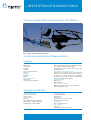
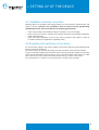
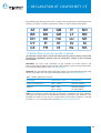
1
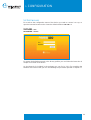
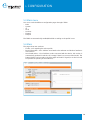
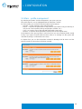
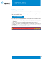
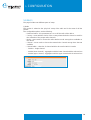
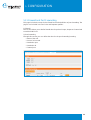
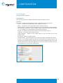
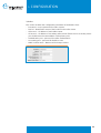
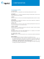
INSTALLATION AND MAINTENANCE
GUIDE - NAAWIGO MINI N
INDEX
1 VERIFICATION SECTION
4
1.1 Approval
1.2 Revision history
1.3 Definitions, acronyms and abbreviations
4
4
4
2 INTRODUCTION
5
2.1 Compliance with R&TTE directives
2.2 Restrictions of use: ministerial regulations
2.3 Warnings
5
5
5
3 DESCRIPTION OF NAAWIGO MINI N
7
3.1 Package content
3.2 The device
3.3 Power supply with Passive Poe switch (OPTIONAL)
3.4 Technical specification of Naawigo Mini N
7
7
8
8
4 SETTING UP OF THE DEVICE
9
4.1 Installation and inter-connection
4.2 Preparing and switching on the device
9
9
5 CONFIGURATION
10
5.1 N.A.A.W. control panel
5.2 First access
5.3 Main menu
5.4 Main
5.5 Main – profile management
5.6 Change of parameters
5.7 System
5.8 IP
5.9 Wi-Fi
5.10 Services
5.11 Firewall and Port Forwarding
5.12 Hotspot
5.13 Default profiles
5.14 Troubleshooting
5.14.1 The N.A.A.W. assigned IP address is not available
5.15 Reset of the device
5.15.1 Password reset
5.15.2 Reset of the device
10
11
12
12
13
14
15
16
19
23
24
27
31
31
32
32
32
2
INDEX
6 MATERIAL DISPOSAL
33
6.1 Toxic substances
33
7 DECLARATION OF CONFORMITY CE
34
7.1 Restrictions of use in some countries
7.2 Restrictions of use of the device
7.3 Power output
7.4 Naawigo Mini N
34
35
35
36
3
1.
VERIFICATION SECTION
1.1 Approval
APPROVED BY
POSITION
DATE
Nicola De Carne
Wireless Networking Director - Wi-Next S.r.l.
14th Oct 2011
REV.
AUTHOR
DESCRIPTION
DATE
00
Wi -Next S.r.l.
First draft
15th Jun 2008
01
Wi-Next S.r.l.
Revision
9th Mar 2010
02
Wi-Next S.r.l.
Revision
20th Jan 2011
03
Wi-Next S.r.l.
Revision
14th Oct 2011
Further updates and related revisions of the present manual are available on-line at the
following address: www.winext.eu/wiki.
1.3 Definitions, acronyms and abbreviations
Wireless devices router:
Naawigo
Mini
frequency:
2,412 GHz - 2,472 GHz
standard:
IEEE 802.11 b/g/n – IEEE 802.11 d – IEEE 802.11 e
– IEEE 802.11 i
power supply:
120/240 V autosensing - 5-24 V output
4
2.
INTRODUCTION
Thank you for purchasing this Naawigo product. This document contains full
documentation relating to the product, including the declaration of conformity. The
user’s guide gives all the information regarding installation and testing of the Naawigo
Mini N, and its subsequent periodic maintenance.
2.1 Compliance with R&TTE directives
Wi-Next S.r.l. declares that the Naawigo Mini N complies with the essential requirements
and relevant provisions of Directive 1999/5/EC.
2.2 Restrictions of use: ministerial regulations
Please note that the use of this device is regulated by:
1 Legislative Decree 08/01/2003 N.259, Articles 104 (activity subject to general
authorisation) and 105 (free use for personal use);
2 Ministerial Decree 28/05/2003 and subsequent amendments to the provision of
private and public access to networks and telecommunications services.
2.3 Warnings
This manual sets out information to anyone in charge of:
• installation.
• maintenance.
• network administration or anyone employed in a technical capacity - provided they
are informed about the risks and safety standards regarding the installation, operation
and maintenance of electric radio communications equipment.
When carrying out the installation you must check the functionality of the Naawigo Mini N.
Do not take any corrective action unless you are certain about the result.
Do not dismantle the device. Taking apart the device will invalidate the warranty.
In case of doubt, please contact our technical support section (e-mail: [email protected]).
5
2.
INTRODUCTION
The manufacturer will not be liable for any damage to property or injuries in case of:
•
•
•
•
•
•
•
improper use of the device,
use of the device by untrained staff,
improper installation,
faulty or inadequate materials used for the installation,
unauthorised modifications,
use of non genuine spare parts,
non-compliance with the recommendations contained in this document.
The manual covers only the use of the application provided by the manufacturer and
under existing legislation relating to data transmission by radio.
6
3.
DESCRIPTION OF NAAWIGO MINI N
3.1 Package Content
The package contains:
• Wi-Fi Mini Naawigo N device with double 2 dBi omni-directional antennas.
• Power supply 230V/24V.
• Jig for wall mounting.
• Passive PoE Switch (OPTIONAL).
• User manual on CD-ROM.
3.2 The device
LED:
- Power
- Diagnostic
-
Wireless
signal
strenght /
throughput
led
indicator*
*The use of leds is
related with the
active profile (see
chapter 5.13)
Power DC Jack
LAN port
WAN port
Reset button
7
3.
DESCRIPTION OF NAAWIGO MINI N
3.3 Power supply with Passive Poe switch (OPTIONAL)
Fig. 1 Detail: Power adapter with POE
3.4 Technical specification of Naawigo Mini N
Features
Operating Modes
NAAW Mesh
Access point
Repeater
Gateway
Access Controller Radius
WAN Type
Static IP
Dynamic IP
PPPoE
Device Management
Web Server
Telnet or Secure Shell (SSH)
Virtual Access Point (VAP) - Configurazione SSH
Up to 4 SSIDs with unique MAC Addresses (BSSID)
802.1q VLAN tag per VAP with Bridging
Configurable Security (WEP, TKIP, AES, MAC
Filtering) per VAP
SSID multipli - Configurazione SSH
Supports up to 4 virtual access points (VAP) per
radio, with unique BSSIDs. Traffic from each VAP can
be tagged to a unique VLAN and /or bridged if
required. Each VAP will be able to configure their
own security (WEP, TKIP, and AES).
Advanced Features
DHCP server
DNS forwarder
Other Prominent Features
IEEE 802.11h (DFS & TPC) DFS (On/Off) Ability
Antenna Alignment Graph
Technical specification
Dimension and Weight
100mm x 76mm x 26mm
Weight: 130 gr
Hardware features
Linux OS
CPU Atheros AR7240 - 400 MHz
32Mb SDRAM - 8 Mb FLASH RAM
LAN Interface: 2x10/100 Mbps
Integrated Antennas
2x2 dBi antenna 360°
802.11a/b/g/n
Environment
Temperature: from -20°C to +70°C
Humidity: from 5% to 95%
Consumption
Max Consumption 5,5 W
Power supply
5-24 V DC
Power with Passive PoE 24V DC
8
4.
SETTING UP OF THE DEVICE
4.1 Installation and inter-connection
Naawigo Mini N is equipped with safety features for the protection against direct and
indirect contact. However, the installation must be carried out by appropriately
qualified personnel who must observe the following precautions:
• check the package and promptly notify the supplier in case of damage,
• make sure access points, antennas and support structures are properly installed to
avoid health hazards,
• make sure that installation of the access point, antennas and cables is made in
accordance with local regulations regarding safety.
4.2 Preparing and switching on the device
To use the device plug in the power supply to the mains and insert the 220/230V plug
into the socket of the device.
The device starts up and after about 60 seconds it reaches a fully functional status.
If you are using the optional passive PoE switch: plug in the power supply to the mains
and insert the 220/230V plug into the DC jack of the PoE switch and connect a CAT5
UTP cable to the “OUT” port of the switch and to the RJ-45 port of the device.
To fix the device to a wall you can use the jig you can find in the package.
9
5.
CONFIGURATION
5.1 N.A.A.W. control panel
The N.A.A.W. control panel is a Web application that resides on the device and is easily
accessible by pointing the browser to one of the IP addresses of the device, either
wirelessly or by cable.
If you want to configure your PC manually, you must know the address of the N.A.A.W.
interface to which you are connected (the default is 192.168.1.1/24 on Ethernet ports
and wireless network in AP mode). If you do not know the address, you can follow the
discovery procedure outlined in 5.14.1 “Troubleshooting - The device can’t be reached
at the assigned IP adress”.
10
5.
CONFIGURATION
5.2 First access
To accede to the configuration menu of the device you need to connect it to a pc, to
open the Internet browser and to insert the default address 192.168.1.1.
Access data
USERNAME : root
PASSWORD : winext
To restore the default password or the factory profiles you can follow the instruction in
chapter 5.15 Reset of the device.
On the Manual CD included in the package you can find a “.bin” file containing the
firmware of the device that you can use following the procedure reported in chapter 5.7.
11
5.
CONFIGURATION
5.3 Main menu
You can accede the different configuration pages through 6 TABS:
- Main
- System
- IP
- Wi-Fi
- Services
- Firewall
- Hotspot
The TABS are automatically enabled/disabled according to the profile in use.
5.4 Main
The page shows two sections:
- Profile – Info regarding the active profile.
- Board information – Mac Address associated to the ethernet and wireless interfaces
of the device.
- Associated nodes – List of wireless nodes connected with the device; this section is
automatically updated in real time (it is empty if there isn’t an associated node). The
button GRAPH can be used to show the graph of the Wi-Fi signal (it can also be used
to optimize the pointing of the antennas).
12
5.
CONFIGURATION
5.5 Main – profile management
By selecting the button “Profile management” you open a pop-up.
The profile that is in use is highlighted with the indication “Active”.
For each profile you can find a short description and 4 buttons:
- Activate – for the activation of the selected profile.
- Export – it exports the parameters of the profile to save them locally (for backup, to
use pre-set custom profiles during configuration activities, etc.).
- Copy – to create a copy of the selected profile with a new name.
- Restore – it restores all the parameters of the profile to the original setup.
At the bottom of the pop-up there is a box that you can use to upload profiles stored
locally; if you import a profile with the same name of an existing one the system will
overwrite it (asking a confirmation to the user).
In chapter 5.13 you can find all profiles included in Naawigo Mini N device and the
typical scenario for whom they have been created.
13
5.
CONFIGURATION
5.6 Change of parameters
When you change parameters the system automatically checks the value inserted in
each field.
Until the value is not properly formatted it is not possible to save the change e the field
is showed in red. Pressing the “undo” button you can cancel the change made on the
value of the field (or the option).
When you change one or more parameters in the top of the page you can find the menu
for the management of changes with an alert and 4 options:
- Try – It makes a test of the changes.
- Apply and save – To save the changes made to the configuration and to apply them
immediately.
- Save – It saves the changes made without applying them until next reboot.
- Restore – All changes that have been made to the page and not yet saved are
canceled.
When you make more changes to a profile it is better to save them (without applying
them) and to reboot the device from section “System”.
14
5.
CONFIGURATION
5.7 System
The page shows 4 sections:
- System operations – from this section you can logout or reboot the device (operation
that is requie after making different changes to the configuration of the device).
- Change hostname – it allows you to define a new name for the device.
- Change password – it is used to change the password used to accede to the device.
- Firmware upgrade – this section is used to upgrade the firmware of the device;
through the box you can upload a new firmware version (it is a file in .bin format); the
option “Cancel configuration” is used to overwrite the customization made to the
profiles (restoring the device to a default configuration); if you don’t select this option
the device maintain the emended profiles.
15
5.
CONFIGURATION
5.8 IP
In this page you can find up to 4 different sections for the configuration of IP addresses
(the number and the typology of sections that are showed is related to the active profile):
1) Point of access
This network is used as an access point from the client connecting to the device.
The available options are the following:
- Assignment section
- Mode used to assign the IP address: static or dynamic (with assignment made by
the DHCP server to whom the device is connected) - Profiles Access Point,
Repeater and Captive portal.
- Address section
- IP address – profiles Access Point, Repeater, Mesh, Router and Captive portal.
- Network (subnet mask) – profiles Access Point, Repeater, Mesh, Router and
Captive portal.
- Gateway – IP address of the gateway to which the device is connected – Profiles
Access Point, Repeater and Captive portal.
- DNS – IP address of the DNS server used from the device – profiles Access Point,
Repeater and Captive portal.
- STP – option to activate the Spanning Tree Protocol – profiles Access Point and
Repeater.
- Export – option used to export the network (respectively from the ethernet port to
the mesh for the profile “Mesh” and from the wireless network to the Ethernet port
for the profile “Router”) – profiles Mesh and Router.
2) Mesh
This network is used by N.A.A.W. devices to connect among them and creating a mesh
network.
The assignment can be made in two ways:
- NAAW – the address is automatically assigned inside a 10.0.0.0/8 network.
- Static – the address is manually assigned from the user inserting IP address and
subnet mask.
The mesh network is used from all the mesh profiles (Mesh, Mesh GW, Mesh+AP and
Mesh+AP GW).
16
5.
CONFIGURATION
3) WAN
This network is used from the device that is directly connected to the gateway (so that
the device operates as a gateway for the other N.A.A.W. devices and for the clients that
are connected – directly or through other N.A.A.W. devices).
The available options are the following:
- Assignment section
- Mode used to assign the IP address: static or dynamic (with assignment made by
the DHCP server to whom the device is connected) – Profiles Mesh GW, Mesh+AP
GW and Router.
- Address section
- IP address – profiles Mesh GW, Mesh+AP GW and Router.
- Network (subnet mask) – profiles Mesh GW, Mesh+AP GW and Router.
- Gateway – IP address of the gateway to which the device is connected – profiles
Mesh GW, Mesh+AP GW and Router.
- DNS – IP address of the DNS server used from the device – profiles Mesh GW,
Mesh+AP GW and Router.
- Masquerade section (NAT)
- Masquerade (NAT) – option used to enable the masquerade (NAT) of the traffic
coming from the network and passing through the device – profiles Mesh GW,
Mesh+AP GW and Router.
4) Bridge (Access Point + Ethernet)
This network is used to put the Ethernet port and the wireless interface in a bridge:
- Address section
- IP address – profiles Mesh+AP and Mesh+AP GW.
- Network (subnet mask) – profiles Mesh+AP and Mesh+AP GW.
- STP – option to activate the Spanning Tree Protocol – profiles Mesh+AP and
Mesh+AP GW.
- Export – option used to export the network (respectively from the network in Access
Point mode and from the Ethernet port to the mesh network for the profile
“Mesh+AP” and from the wireless network to the Ethernet port for the profile
“Mesh+AP GW”) – profiles Mesh+AP and Mesh+AP GW.
17
5.
-
CONFIGURATION
List of the profiles and the IP configuration available for each:
- Access Point : Point of Access
- Repeater : Point of Access
- Mesh : Point of Access + Mesh
- Mesh GW : WAN + Mesh
- Mesh + AP : Bridge + Mesh
- Mesh + AP GW : WAN + Bridge + Mesh
- Router : WAN + Point of Access
- Captive portal : Point of access
18
5.
CONFIGURATION
5.9 Wi-Fi
The page includes two different parts of setup:
1) Radio
This section is related to the “physical” setup of the radio and is the same for all the
profiles.
The configurable options are the following:
- Radio activation – this parameter turn on or off the radio of the device.
- Country – menu with the choice of the country where the device has to be used for
the activation of the proper radio channels.
- Mode – menu used to choose the radio wireless mode among those available on
the device.
- Channel – menu used to choose the transmission channel among those that are
available.
- Channel width – selection of channel width to be used in 802.11 N mode
- 20 MHz – single channel
- 40 MHz (lower channel) – aggregation with the lower channel with the selected one
- 40 MHz (upper channel) – aggregation with the upper channel with the selected one
19
5.
CONFIGURATION
2) Virtual Interfaces of the radio
This section is related to the setup of the virtual interfaces which alolow to use the radio
for the different services; the interfaces that can be used are 3 (the number and typology
of the section showed in the page are related to the active profile):
- Point of access
- Station
- Mesh
For each interface you can find, near its name, a small icon which allows to do the site
survey, that is tha real time analysis of the radio frequencies to detect the presence of
other wireless networks with the main info regarding them.
20
5.
CONFIGURATION
- Point of access
This interface supply the “traditional” service of wireless access.
The options that can be configured are the following:
- SSID – name of the wireless network.
- Hide – option used to make the network invisible.
- WDS – option used to activate the WDS service (it has to be enabled when you use
configuration where the wireless signal is repeated).
- Encryption – menu where you can select the kind of encryption of the signal; when
you activate one kind of encryption the page shows a box where you have to insert
the security key.
- Station
This interface allows the device to connect as a client to a Wi-Fi network and it is used
when the profile “Repeater” is activated. The options that can be configured are the
same used for the “Point of Access” with an additional field:
- BSSID – this is the Mac Address of the Access Point on which you want to lock the
connection of the client interface. It is used when you have many Access Points
with the same SSID and you want to lock the client to a specific AP.
21
5.
CONFIGURATION
- Mesh
This interface creates the N.A.A.W. mesh network among the devices.
The options that can be configured are the following:
- Mesh mode – it allows you to choose between Ad-hoc mode (classic setup) and
Ad-hoc demo (the same as the previous one but without any check packet
exchanged among the network).
- SSID – name of the wireless network.
- Hide – option used to make the network invisible.
- WDS – option used to activate the WDS service (it has to be enabled when you use
configuration where the wireless signal is repeated).
- identifier used by the devices to connect with each other; if you set-up the same
BSSID and the same radio channel the device can be connected even if they have
different SSID (this feature can be used for example to give different SSID names
to the devices installed in differente sites) – the BSSIDshould have the format of a
mac address (six pairs of hexadecimal values separated with the symbol “:”).
- Encryption – menu where you can select the kind of encryption of the signal; when
you activate one kind of encryption the page shows a box where you have to insert
the security key.
-
List of the profiles and the virtual interfaces to be configured for each:
- Access Point : Point of Access
- Repeater : Station + Point of Access
- Mesh : Mesh
- Mesh GW : Mesh
- Mesh + AP : Mesh + Point of Access
- Mesh + AP GW : Mesh + Point of Access
- Router : Point of Access
- Captive Portal : Point of access
22
5.
CONFIGURATION
5.10 Services
This page can show up to 3 different configuration sections (first two are used by all the
profiles while the third is used only by part of them):
1) HTTP
Setup of the door through which the device can be reached via HTTP connection.
2) SSH
Setup of the door through which the device can be reached via SSH connection.
3) DHCP SERVER (profiles Mesh*, Mesh GW**, Mesh+AP, Mesh+AP GW, Router).
Configuration of the DHCP server.
The options that can be configured are the following:
- Enabling – this allows you to enable/disable DHCP service.
- Domain – this is the domain name inside which the DHCP server works.
- Authoritative – option to enable authoritative.
- Mask – netmask to be assigned to the clients.
- Start – Initial IP to be assigned from DHCP.
- Limit – maximum number of IP address that can be assigned by the DHCP.
- Lease – release time of the IP address due to inactivity of the client (it can be set at
15/30/60 minutes or without limit).
*for this profile it operates only through the Ethernet port.
**for this profile it is active only as a DNS server.
N.B.: for the profile Captive portal-client the parameters for DHCP are set up directly
in hot spot section
23
5.
CONFIGURATION
5.11 Firewall and Port Forwarding
This page includes the setup for the firewall and for the definition of port forwarding. The
page is not included in Access Point and Repeater profiles..
1) Firewall
This section allows you to define firewall rules for packet in Input, Output or Forward and
to enable SYN Flood.
2) Port forwarding
Through this section you can define the rules for the port forwarding inserting:
- Name of the rule.
- Protocol to be used.
- Destination port.
- Destination IP.
- Forward port.
24
5.
CONFIGURATION
5.12 Hotspot
The page include 3 sections:
1) Enabling area
Check box that allows to enable/disable the hotspot and radius service
2) Hotspot
This section contains the parameters for the configuration of hot spot service:
- DNS 1 – IP address of primary DNS server used by the device
- DNS 2 – IP address of secondary DNS server used by the device
- Subnet hotspot – subnet used for the hotspot service (it should be inserted following
the Unix/Linux parameters -> the IP address range is followed by the class after the
“/”; i.e. /24 refers to a netowrk with the subnet 255.255.255.0)
- IP UAM – IP address used from the device to offer the hotspot service
- UAM port – port used for the hotspot service
- UAM homepage – address of the captive page for the user which are not yet
authenticated
- URL portal – address of Radius portal
- Password UAM – password used for the connection with the authentication portal
- Free Url – list of web/Ip address that are not blocked from the captive portal; for all
teh sites not included in the list a redirect is forced to the perdefined page for all users
without authentication. Near each address you can find a “Remove” button. To insert
a new address you can use the “add” button.
25
5.
CONFIGURATION
3) Radius
This section includes the configuration parameters of the Radius client:
- Password – access password for radius system
- NAS Id – identification name of the location in the radius server
- IP Server 1 – IP address of main radius server
- IP Server 2 – IP address of secondary radius server (if there isn’t a secondary server
you should insert the same address of the primary one)
- Authentication port – port used for radius authentication
- Accounting port – port used for Radius access
- WISP location name – Name used for hotspot service
26
5.
CONFIGURATION
5.13 Default profiles
1) Access Point
The device works as a standard Access Point that provides the Wi-Fi service.
2) Repeater
The device works as a wireless repeater that, being connected with a main Access
Point, extends its Wi-Fi coverage.
3) Mesh
The device works as a node of a mesh network (single Radio Interface in ad hoc mode).
4) Mesh GW
The device works as a gateway to Internet in a mesh ad hoc network (for a network of
devices using “Mesh” Profile).
5) Mesh + AP
The device works as a node of a mesh ad hoc network providing Wi-Fi service as an
Access Point through a second virtual interface.
6) Mesh + AP GW
The device works as a gateway to Internet in a mesh ad hoc network + AP (for a network
of devices using ‘Mesh + AP’ Profile).
7) Router
The device works as an Access Point operating also as a gateway to the Internet
providing basic services (i.e.: DHCP, DNS, NAT).
8) Captive Portal – Client
The device works as a hot-spot for public access, connected to a Radius autentication
system.
LEDs indicators
The use of LEDs indicators changes according to the profile that is in use:
- For “Repeater”profiles the LEDs shows the strrenght of the wireless radio link
between the client interface of the devices and the access point it is connected to:
according to the strenght of the signal 1 to 4 leds turn on (1 led weak signal – 2 leds
average signal – 3 leds good signal – 4 leds excellent signal)
- For all of other profiles LEDs show the real time throughput of the device (increasing
according to the number of led turned on).
27
5.
CONFIGURATION
Access Point Profile
You can use the profile Access Point to provide wireless service on a local area.
Repeater Profile
You can use this kind of network when you need to create a point-to-point connection
with one devices operating as a repeater to extend wireless coverage.
A - Access Point Profile
B - Repeater Profile
28
5.
CONFIGURATION
Ad-Hoc Mesh Network
The ad-hoc mesh network allows you to create a level 3 infrastructure with automatic
management of routing among the nodes.
A - Mesh GW Profile
B - Mesh Profile
Ad-Hoc Mesh Network + Access Point
The ad-hoc mesh network allows you to create a level 3 infrastructure with automatic
management of routing among the nodes. All nodes also provide Wi-Fi service in Access
Point mode.
A - Mesh + AP GW Profile
B - Mesh + AP Profile
29
5.
CONFIGURATION
Access Point with routing service
In this configuration besides operating a san access point the device acts as a router.
You should use Router profile.
Captive Portal with Client Radius
With this profile the device works as an access point and a router operating also as an
access controller of a Radius authentication system.
30
5.
CONFIGURATION
5.14 Troubleshooting
5.14.1 The device can’t be reached at the assigned IP address
During the configuration of N.A.A.W. devices it is possible, for whatever reason, that you
are unable to identify the IP address of the interface through which you are connected
to the device.
This may occur because the interface is configured with N.A.A.W. protocol (which
calculates the IP address starting from a MAC address), or because there is a duplication
of the IP address or simply because of an oversight on the part of the administrator.
If this is the case, because every interface is configured with a link-local type IP address
(169.254.0.0/16), N.A.A.W. provides a very simple solution
The procedure is as follows:
• configure the interface on the PC connected to NAAW with an address of the linklocal type (e.g. 169.254.3.3/16))
• Open a terminal command
• ping address: 169,254,255,255:
o on Linux OS “ping-b 169 254 255 255”. All N.A.A.W. devices physically connected
to the interface, will answer. At this point it is sufficient to identify, by repeated
attempts if necessary, the unit in question by contacting it via the exposed linklocal address.
o on Windows OS command “ping 169254255255” does not show responses by
individual N.A.A.W. and to view addresses that have responded, use the command
“arp-a”.
31
5.
CONFIGURATION
5.15 Reset of the device
If necessary the device can be partially or totally restored .
To reset the device you have to unpowered it, to press the reset button and power again
the device.
Depending on the time of pressure of the reset button you choose the type of reset.
5.15.1 Password reset
To reset the password you should follow the restore procedure and keep the reset
button pressed for 0 to 3 seconds when turning on the device.
If the operation is made correctly the device maintains all the configurations e the
password is reset to the default “winext” (the username is always “root”).
5.15.2 Reset of the device
To totally reset the device you should follow the restore procedure and keep the reset
button pressed for 8 to seconds when turning on the device.
If the operation is made correctly the device is reset to factory configuration (restore of
all profiles and of the password).
32
6.
MATERIAL DISPOSAL
6.1 Toxic substances (RoHS Compatibility)
The components used in the manufacturing of the N.A.A.W. device comply with the
current regulations on protection of the environment. The assembly of components
made by the manufacturer does not introduce risk factors for the operator or the
environment. The device is not made with materials requiring sensitive handling such as
asbestos, PCB-PCT, phosphorus, cadmium, or halogens (fluorine, chlorine, bromine,
iodine).
33
7.
DECLARATION OF CONFORMITY CE
The Naawigo Mini N range of products complies with the legislation requirements of the
following countries, for which a request for release on their markets was granted:
AT
BE
CH
CY
CZ
DE
DK
EE
FI
FR
GB
GR
HU
IE
IS
IT
LT
LU
LV
NL
NO
RO
SE
SI
SK
7.1 Restrictions of use for specific countries
This product can be used in all EU countries (and any other country in which the
EU directive 1999/95/EC applies) with no restrictions, except for the countries
listed below:
BELGIUM: you must send notification to the Institute for Postal Services and
Telecommunications (BIPT) for each wireless device which covers more than 300 meters.
For more information please visit: http://www.bipt.be.
FRANCE: you must partially reduce the power output as per the table below when using
devices for outdoor use. For more information please visit: http://www.arcep.fr.
Table 1: Power applicable in France
ASSIGNED
FREQUENCY (MHz)
POWER EIRP
Indoor (no restrictions)
2400 - 2483.5
100 mW (20dBm)
Outdoor
2400 - 2454
2454 - 2483.5
100 mW (20dBm)
10 mW (10dBm)
ITALY: This product complies with the specifications of National and Radio Interface
and meets the requirements of the National Frequency Allocation Plan. However, if not
installed for private use, the use of 2.4 GHz Wireless LAN products requires a “General
Permission “. For more information see http http://www.comunicazioni.it.
34
7.
DECLARATION OF CONFORMITY CE
7.2 Restrictions of use of the device
This product has been designed to be used with integrated antenna and / or with
dedicated external antenna, if included in the package.
If external antennas, connected through a special cable guide, are used please note that
legislation stipulates the radiated power must not exceed 100 mW EIRP.
7.3 Power Output
In accordance with local regulations of the country where you install the NAAW, you
need to adjust the transmission power according to the approved limits.
35
7.
DECLARATION OF CONFORMITY CE
8.4 Naawigo Mini N
/,/Z/KE/KE&KZD/d͛
/,/Z/DK^KddKEK^dZ^>h^/sZ^WKE^/>/d͛,>͛WWZdKWZ
d>KDhE//KE/Yh/^KddK^Z/ddK͗
WZKhddKZ͗
/E/Z/K͗ WZKKddK͗
&D/'>/͗
DK>>K͗
DZ͗
&hE/KE͗
tŝͲEĞdžƚƐƌů
sŝĂ&ĞƌƌĞƌŽϭϬʹϭϬϬϵϴĂƐĐŝŶĞsŝĐĂZŝǀŽůŝdKͲ/ƚĂůŝĂ
dĞů͗Ϭϭϭͬϵϱ͘ϵϬ͘ϭϰϬ &Ădž͗Ϭϭϭͬϵϱ͘ϵϬ͘ϮϬϬ
EĂĂǁŝŐŽD/E/E
EĂĂǁŝŐŽ
Ϯ͕ϰE
tŝͲEĞdžƚ
ƉƉĂƌĂƚŽŝŶĚŽŽƌĚŝƌŝĐĞƚƌĂƐŵŝƐƐŝŽŶĞĚĂƚŝ/WŶĞůůĞďĂŶĚĞZ>EĞ,/WZ>E͕
Ϯ͕ϰ͕ĐŽŶƌŝĐĞƚƌĂƐŵĞƚƚŝƚŽƌĞĞƉƌŽĐĞƐƐŽƌĞĚŝĐŽŶƚƌŽůůŽ
͛KE&KZD
>>/Zdd/sϭϵϵϵͬϱͬ
>>^'hEd/EKZDZDKE/d͗
ŝƌĞƚƚŝǀĞZĂĚŝŽ͗
EϯϬϬϯϮϴsϭ͘ϳ͘ϭ;ƌƚ͘ϯƉĂƌĂŐƌĂĨŽϮͲ&ƵŶnjŝŽŶĂůĞZĂĚŝŽͿ
ŽŵƉĂƚŝďŝůŝƚăůĞƚƚƌŽŵĂŐŶĞƚŝĐĂ͗
EϯϬϭϰϴϵʹϭsϭ͘ϴ͘ϭĞEϯϬϭϰϴϵͲϭϳsϮ͘ϭ͘ϭ;ƌƚ͘ϯƉĂƌĂŐƌĂĨŽϭ͕ůĞƚƚĞƌĂďͿͲDͿ
^ŝĐƵƌĞnjnjĂĞůĞƚƚƌŝĐĂ͗
EϲϬϵϱϬͲϭ͗ϮϬϬϲ;ƌƚ͘ϯƉĂƌĂŐƌĂĨŽϭ͕ůĞƚƚĞƌĂĂͿͲ^ŝĐƵƌĞnjnjĂůĞƚƚƌŝĐĂͿ
>ƵŽŐŽ͗
ZŝǀŽůŝ
ĂƚĂ͗ KƚƚŽďƌĞϮϬϭϭ
&ŝƌŵĂĚĞůƌĞƐƉŽŶƐĂďŝůĞ͗
EŝĐŽůĂĞĂƌŶĞ
:L1H[W²9LD)HUUHUR²&DVFLQH9LFD5LYROL72
WHO8II²ID[
ZZZZLQH[WHXLQIR#ZLQH[WHX
36