1
SNE2020G-P and SNE2020G-S
2-Port Network Extenders Installation Instructions
Document Number SNE2-A2-GN11-10
July 2005
Contents
Software and Firmware License Agreement .................................................
2
Product Documentation Online .....................................................................
3
Introduction ...................................................................................................
4
Package Contents .........................................................................................
4
Connecting to Power .....................................................................................
5
Switchpack Configuration .............................................................................
6
Connecting the SHDSL Lines .......................................................................
8
Connecting the Ethernet Line ....................................................................... 10
Ferrite Chokes .............................................................................................. 10
LED Indicators .............................................................................................. 11
EMI Notices .................................................................................................. 13
ACTA Customer Information ......................................................................... 13
Supplier's Declaration of Conformity ............................................................. 14
Notice to Users of the Canadian Telephone Network ................................... 15
CE Marking ................................................................................................... 15
Japan Notice ................................................................................................. 15
Important Safety Instructions ........................................................................ 15
1
Software and Firmware License Agreement
ONCE YOU HAVE READ THIS LICENSE AGREEMENT AND AGREE TO ITS
TERMS, YOU MAY USE THE SOFTWARE AND/OR FIRMWARE INCORPORATED
INTO THE PARADYNE PRODUCT. BY USING THE PARADYNE PRODUCT YOU
SHOW YOUR ACCEPTANCE OF THE TERMS OF THIS LICENSE AGREEMENT.
IN THE EVENT THAT YOU DO NOT AGREE WITH ANY OF THE TERMS OF THIS
LICENSE AGREEMENT, PROMPTLY RETURN THE UNUSED PRODUCT IN ITS
ORIGINAL PACKAGING AND YOUR SALES RECEIPT OR INVOICE TO THE
LOCATION WHERE YOU OBTAINED THE PARADYNE PRODUCT OR THE
LOCATION FROM WHICH IT WAS SHIPPED TO YOU, AS APPLICABLE, AND YOU
WILL RECEIVE A REFUND OR CREDIT FOR THE PARADYNE PRODUCT
PURCHASED BY YOU.
The terms and conditions of this License Agreement (the “Agreement”) will apply to the
software and/or firmware (individually or collectively the “Software”) incorporated into
the Paradyne product (the “Product”) purchased by you and any derivatives obtained
from the Software, including any copy of either. If you have executed a separate written
agreement covering the Software supplied to you under this purchase, such separate
written agreement shall govern.
Paradyne Corporation (“Paradyne”) grants to you, and you (“Licensee”) agree to accept
a personal, non-transferable, non-exclusive, right (without the right to sublicense) to use
the Software, solely as it is intended and solely as incorporated in the Product
purchased from Paradyne or its authorized distributor or reseller under the following
terms and conditions:
1. Ownership: The Software is the sole property of Paradyne and/or its licensors. The
Licensee acquires no title, right or interest in the Software other than the license
granted under this Agreement.
2. Licensee shall not use the Software in any country other than the country in which
the Product was rightfully purchased except upon prior written notice to Paradyne
and an agreement in writing to additional terms.
3. The Licensee shall not reverse engineer, decompile or disassemble the Software in
whole or in part.
4. The Licensee shall not copy the Software except for a single archival copy.
5. Except for the Product warranty contained in the manual, the Software is provided
“AS IS” and in its present state and condition and Paradyne makes no other
warranty whatsoever with respect to the Product purchased by you. THIS
AGREEMENT EXPRESSLY EXCLUDES ALL OTHER WARRANTIES, WHETHER
EXPRESS OR IMPLIED, OR ORAL OR WRITTEN, INCLUDING WITHOUT
LIMITATION:
a.
Any warranty that the Software is error-free, will operate uninterrupted in your
operating environment, or is compatible with any equipment or software
configurations; and
2
b.
ANY AND ALL IMPLIED WARRANTIES, INCLUDING WITHOUT LIMITATION
IMPLIED WARRANTIES OF MERCHANTABILITY, FITNESS FOR A
PARTICULAR PURPOSE AND NON-INFRINGEMENT.
Some states or other jurisdictions do not allow the exclusion of implied warranties
on limitations on how long an implied warranty lasts, so the above limitations may
not apply to you. This warranty gives you specific legal rights, and you may also
have other rights which vary from one state or jurisdiction to another.
6. IN NO EVENT WILL PARADYNE BE LIABLE TO LICENSEE FOR ANY
CONSEQUENTIAL, INCIDENTAL, PUNITIVE OR SPECIAL DAMAGES,
INCLUDING ANY LOST PROFITS OR LOST SAVINGS, LOSS OF BUSINESS
INFORMATION OR BUSINESS INTERRUPTION OR OTHER PECUNIARY LOSS
ARISING OUT OF THE USE OR INABILITY TO USE THE SOFTWARE,
WHETHER BASED ON CONTRACT, TORT, WARRANTY OR OTHER LEGAL OR
EQUITABLE GROUNDS, EVEN IF PARADYNE HAS BEEN ADVISED OF THE
POSSIBILITY OF SUCH DAMAGES, OR FOR ANY CLAIM BY ANY THIRD
PARTY.
7. The rights granted under this Agreement may not be assigned, sublicensed or
otherwise transferred by the Licensee to any third party without the prior written
consent of Paradyne.
8. This Agreement and the license granted under this Agreement shall be terminated
in the event of breach by the Licensee of any provisions of this Agreement.
9. Upon such termination, the Licensee shall refrain from any further use of the
Software and destroy the original and all copies of the Software in the possession of
Licensee together with all documentation and related materials.
10. This Agreement shall be governed by the laws of the State of Florida, without
regard to its provisions concerning conflicts of laws.
Product Documentation Online
Complete documentation for Paradyne products is available at www.paradyne.com.
Select Support → Technical Manuals.
To order a paper copy of a Paradyne document, or to speak with a sales representative,
please call 1-727-530-2000.
3
Introduction
The family of EFM Based Network Extenders provide an extremely flexible and easy to
use solution for providing Ethernet based services to subscribers throughout the service
providers network.
The SNE2020 is fully DSL The Easy Way™ compliant, so that configuration
requirements are removed completely, allowing this device to be installed into the
customer premises quickly. The SNE2020 is also fully DSL The Easy Way packet based
utilizing 100 percent packet-based technology for optimum throughput and reliability.
The SNE2020 is a loop bonding endpoint for EFM-based 12000 and 4000 BLCs that
provides up to 4.6 Mbps of symmetrical bandwidth using two copper pairs.
The SNE2020 features two SHDSL ports, each capable of up to 2.3 Mbps symmetrical
bandwidth. When used with any loop bonding compatible product, two copper pairs may
be used to deliver double the bandwidth at any given distance. In addition, the SNE2020
can be used in a point to point deployment for high speed copper connections between
two locations.
Loop bonded SHDSL provides automatic load balancing and fail-over to provide
optimum redundancy and data throughput, all delivered with a plug and play ease of
use.
Package Contents
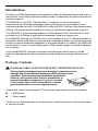
! HANDLING PRECAUTIONS FOR STATIC-SENSITIVE DEVICES
This product is designed to protect sensitive components from
damage due to electrostatic discharge (ESD) during normal
operation. When performing installation procedures,
however, take proper static control precautions to
prevent damage to equipment. If you are not sure
of the proper static control precautions, contact
your nearest sales or service representative.
Unpack and Inspect the Equipment. The following components should be included:
1 SNE2020G
1 Power supply
If there is any visible damage, do not attempt to connect the device. Contact your sales
or service provider.
4
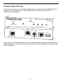
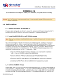
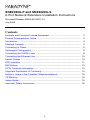
Connecting to Power
Plug the power supply into the Power Adapter port on the back of the SNE2020G and
connect it to your power source. Verify that the Power LED on the front of the
SNE2020G is illuminated.
SDSL Network Extender 2000
SDSL 2
SDSL 1
SDSL Connection
SNE2020
SDSL Connection
Power
Collision
Rx
Tx
Ethernet Connection
Lnk
SDSL 2
Power Adapter
Configuration
1 2 3 4
Ethernet Connection
5V DC
SDSL 1
04-17573
Upon start up, the Ethernet link will remain disabled (as indicated by solid illumination of
the Ethernet Rx, Tx, and Lnk LEDs) until at least one of the two SHDSL connections has
been established.
5
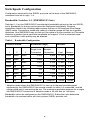
Switchpack Configuration
Configuration switches for the SHDSL ports are on the back of the SNE2020G,
numbered from left to right, 1–4.
Bandwidth: Switches 1–3 (SNE2020G-P Only)
Switches 1–3 on the SNE2020G-P provide eight bandwidth options for the two SHDSL
ports. Bandwidth for the two ports cannot be configured individually. Distance
capabilities listed in the following table assume the use of 26 American Wire Gauge
(AWG) cable. Connections made with cable of a heavier gauge will link up at greater
distances. Your SNE2020G may not link up if the cable is in poor condition or if the cable
distance is greater than a particular bandwidth will support. If link is acheived under
such conditions, traffic quality may be affected.
Table 1. Bandwidth Configuration
Switch Position
Bandwidth (kbps)
3
Single Line
Connection
Distance
Double Line
Bonded
Connection
1
2
down
down
down
2,320
4,640
11,300
3,444
down
down
up
2,064
4,128
12,200
3,719
down
up
down
1,552
3,104
12,800
3,901
down
up
up
1,040
2,080
16,000
4,877
up
down
down
784
1,568
16,800
5,121
up
down
up
528
1,056
18,400
5,608
up
up
down
400
800
19,400
5,913
up
up
up
Adaptive*
Adaptive*
Varies
Varies
Feet
Meters
* Adaptive mode allows the SNE2020G-P to train up to the best possible speed
supported by the SNE2020G-P, the remote modem to which it is connected, and the
copper cable pair(s) connecting the two. The maximum reachable distance for a single
line SNE2020G-P connection in Adaptive mode is 25,400 feet (at 144 kbps).
Bandwidth cannot be configured on the SNE2020G-S. Subscriber units determine
bandwidth via communication with their partner SHDSL provider unit.
6
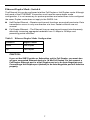
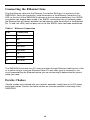
Ethernet Duplex Mode: Switch 4
The Ethernet link can be configured at either Full Duplex or Half Duplex mode. Although
both ends of the ETHERNET connection must have the same duplex mode
configuration, it is not necessary for partner providers and subscribers to be configured
the same. Duplex mode does not apply to the SHDSL link.
Half Duplex Ethernet – Receive and transmit functions are mutually exclusive. Data
transmission occurs in only one direction at a time. Packet collisions are not
unusual.
Full Duplex Ethernet – The Ethernet line can receive and transmit simultaneously,
effectively increasing aggregate bandwidth from 10 Mbps to 20 Mbps and
preventing packet collisions.
Table 2. Ethernet Duplex Mode Configuration
Switch 4
Duplex Mode
down
Half Duplex
up
Full Duplex
CAUTION:
If you set the SNE Provider or Subscriber unit to Full Duplex, you must also
set your connected Ethernet device to 10 Mb Full Duplex. Do not connect a
Full Duplex Ethernet port to a Half Duplex port or to an Auto-Negotiate port.
Connecting a Half Duplex port (default) to an Auto-Negotiate port will function
properly.
7
Connecting the SHDSL Lines
An SNE2020G-S must be connected via an SHDSL line to an SNE2020G-P, a Mini
DSLAM, a Micro DSLAM, or a Broadband Access Concentrator (BAC) interface module.
Neither a subscriber-to-subscriber nor a provider-to-provider connection will function.
Loop Bonded Connection
Using two SHDSL lines for one network connection (loop bonding) will yield twice the
speed of a single SHDSL connection. A second SHDSL line also provides a backup
should one of the lines become disabled.
The SHDSL equipment at both ends of a subscriber line must be loop bonding capable
in order for the SNE2020G to utilize the loop bonding feature. Refer to the SDSL Loop
Bonding Product to Product Feature Compatibility document on the Paradyne website
for a complete list of SDSL loop bonding capable products and required firmware
versions.
Procedure
To establish a loop bonding connection:
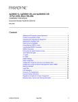
1. Plug your SHDSL cables into the SHDSL RJ45 ports (SDSL 1 and SDSL 2) on the
back of the SNE2020G. The order of connection is not important.
2. Verify both connections: the SDSL 1 and SDSL 2 LEDs on the front of the
SNE2020G will pulse green to indicate the connections are established and
operational.
Single Line Connection
Procedure
To establish a single line connection:
1. Plug your SHDSL cable into one of the two SHDSL RJ45 ports on the back of the
SNE2020G. Either port (SDSL 1 or SDSL 2) may be used.
2. Verify the connection: the SDSL LED on the front of the SNE2020G (SDSL 1 or
SDSL 2, depending upon which port was connected) will pulse green to indicate the
connection is established and operational.
Link up time between local and remote SHDSL network extenders can vary from one to
five minutes depending on the quality, gauge and distance of the copper cables. If cable
distance is greater than a particular bandwidth will support, the units may not link up or,
if they do achieve link, traffic quality may be affected.
8
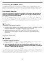
RJ45 Port
Cable and RJ45 Connector
Table 3. SDSL RJ45 Port
Pin
Connection
1
not used
2
not used
3
not used
4
Ring
5
Tip
6
not used
7
not used
8
not used
9
Connecting the Ethernet Line
Plug the Ethernet cable into the Ethernet Connection RJ45 port on the back of the
SNE2020G. Verify the connection: solid illumination of the Ethernet Connection Lnk
LED on the front of the SNE2020G indicates a link has been established, if an SHDSL
connection has already been made. If an SHDSL connection has not yet been made,
the Ethernet link will remain disabled (as indicated by solid illumination of the Ethernet
Rx, Tx and Lnk LEDs) until at least one of the two SHDSL links has been established.
Table 4. Ethernet Connection
Pin
Connection
1
Rx+
2
Rx-
3
Tx+
4
not used
5
not used
6
Tx-
7
not used
8
not used
The SNE2020G connects to a PC using a straight-through Ethernet cable and to a hub
or a switch using a crossover Ethernet cable. For any other type of connection, the
circuit presented by the Ethernet device you are connecting to determines the type of
cable you need.
Ferrite Chokes
If ferrite chokes are included with your network extender, install them on all DC power
and signal cables. Position the ferrite chokes as close as possible to the body of the
SNE2020G.
10
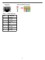
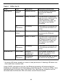
LED Indicators
Table 5. LEDs (1 of 2)
LED
State
Indication
Additional Information
Power
Solid Green
SNE2020G is
operational
If the Power LED is not
illuminated, it is unlikely the
SNE2020G is receiving power.
None of the LEDs will be
illuminated.
SDSL 1 & 2
Pulsing
Green*
SHDSL
connection is
established and
active
Traffic is flowing.
Solid Green
Problematic
SHDSL
connection
A connection exists but there is
indication of a problem with the
SHDSL line.
No
Illumination
No SHDSL
connection
If both SHDSL connections are
lost, the Ethernet LEDs will
have these states:
Collision: Off
Rx and Tx: Solid Amber
Lnk: Solid Green
Ethernet
Collision
No
Illumination
Standard
Either there is no traffic or
traffic is flowing without any
collisions. If there is no
Ethernet connection, the
Ethernet Collision LED will
remain unlit by default.
An SNE2020G in Full Duplex
mode does not have collisions;
the Ethernet Collision LED is
only applicable in Half Duplex
mode.
Flashing
Red*
Packet collision(s)
The Ethernet packet(s) will
automatically be retransmitted.
Solid Red
Warning
There is a potential traffic
problem over the Ethernet
segment.
11
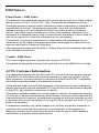
Table 5. LEDs (2 of 2)
LED
State
Indication
Additional Information
Ethernet Rx
Flashing
Amber*
Ethernet activity
The SNE2020G is receiving
data from the Ethernet
network.
Solid Amber
Heavy Rx traffic
The SNE2020G is receiving
large amounts of data from the
Ethernet network. A solid
amber Ethernet Rx LED can
also signify a lost SHDSL
connection.
No
Illumination
No activity
Either there is no Ethernet link
or a link exists but there is no
activity.
Flashing
Amber*
Ethernet activity
The SNE2020G is transmitting
data across the Ethernet
network.
Solid Amber
Heavy Tx traffic
The SNE2020G is transmitting
large amounts of data across
the Ethernet network. A solid
amber Ethernet Tx LED can
also signify a lost SHDSL
connection.
No
Illumination
No activity
Either there is no Ethernet link
or a link exists but there is no
activity.
Solid Green
Ethernet
connection is
established
A solid green Ethernet Lnk
LED can also signify a lost
SHDSL connection.
No
Illumination
No Ethernet
connection
The Ethernet Rx and Tx LEDs
will remain unlit by default.
Ethernet Tx
Ethernet Lnk
* A pulsing LED blinks steadily at a rate of once per second. A flashing LED blinks at a
more rapid, less constant rate.
If both SHDSL connections are lost, the Ethernet connection will automatically be
disabled (as indicated by solid illumination of the Ethernet Rx, Tx and Lnk LEDs). Upon
reestablishment of at least one of the SHDSL links, the Ethernet connection will be
reinstated and the Ethernet LEDs will reflect current Ethernet status.
12
EMI Notices
United States – EMI Notice
This equipment has been tested and found to comply with the limits for a Class A digital
device, pursuant to Part 15 of the FCC rules. These limits are designed to provide
reasonable protection against harmful interference when the equipment is operated in a
commercial environment. This equipment generates, uses, and can radiate radio
frequency energy and, if not installed and used in accordance with the instruction
manual, may cause harmful interference to radio communications. Operation of this
equipment in a residential area is likely to cause harmful interference in which case the
user will be required to correct the interference at his own expense.
The authority to operate this equipment is conditioned by the requirements that no
modifications will be made to the equipment unless the changes or modifications are
expressly approved by Paradyne Corporation.
If the equipment includes a ferrite choke or chokes, they must be installed as described
in the installation instructions.
Canada – EMI Notice
This Class A digital apparatus complies with Canadian ICES-003.
Cet appareil numérique de la classe A est conforme à la norme NMB-003 du Canada.
ACTA Customer Information
This equipment complies with Part 68 of the FCC rules and the requirements adopted
by the ACTA. On the bottom of the network extender is a label that contains, among
other information, a product identifier in the format US:AAAEQ##TXXXX. If requested,
this number must be provided to the telephone company.
A plug and jack used to connect this equipment to the premises wiring and telephone
network must comply with the applicable FCC Part 68 rules and requirements adopted
by the ACTA. See installation instructions for details.
If the network extender causes harm to the telephone network, the telephone company
will notify you in advance that temporary discontinuance of service may be required. But
if advance notice isn't practical, the telephone company will notify the customer as soon
as possible. Also, you will be advised of your right to file a complaint with the FCC if you
believe it is necessary.
The telephone company may make changes in its facilities, equipment, operations or
procedures that could affect the operation of the equipment. If this happens the
telephone company will provide advance notice in order for you to make necessary
modifications to maintain uninterrupted service.
13
If trouble is experienced with this equipment, please contact your local sales
representative, service representative, or distributor directly for any help needed. For
additional information concerning warranty, sales, service, repair, installation,
documentation, training, distributor locations, or Paradyne worldwide office locations,
use one of the following methods:
Internet: Visit the Paradyne World Wide Web site at www.paradyne.com. (Be sure
to register your warranty at www.paradyne.com/warranty.)
Telephone: Call our automated system to receive current information by fax or to
speak with a company representative.
—
Within the U.S.A., call 1-800-795-8004
— Outside the U.S.A., call 1-727-530-2340
If the equipment is causing harm to the telephone network, the telephone company may
request that you disconnect the equipment until the problem is resolved.
The customer may make no repairs to the equipment.
Connection to party line service is subject to state tariffs. Contact the state public utility
commission, public service commission or corporation commission for information.
Supplier's Declaration of Conformity
Place of Issue: Paradyne Corporation
8545 126th Avenue North
Largo, FL 33773-1502
USA
Date of Issue:
7/14/2005
Paradyne Corporation, located at the above address, hereby certifies that the Model
SNE2020G-P, Model SNE2020G-S, Model SNE2000G-P, and Model SNE2000G-S
bearing labeling identification number US:AW2DLNANSNE2020 complies with: the
Federal Communications Commission's ("FCC") Rules and Regulations 47 CFR Part
68, and the Administrative Council on Terminal Attachments ("ACTA")-adopted technical
criteria TIA-968-A, "Telecommunications - Telephone Terminal Equipment -Technical
Requirements for Connection of Terminal Equipment To the Telephone Network,
October 2002," as amended by ANSI/TIA-968-A-3 2004, "Telecommunications Telephone Terminal Equipment -Technical Requirements for Connection of Terminal
Equipment to the Telephone Network - Addendum 3."
Patrick Murphy
Senior Vice President, Chief Financial Officer
14
Notice to Users of the Canadian Telephone Network
NOTICE: This equipment meets the applicable Industry Canada Terminal Equipment
Technical Specifications. This is confirmed by the registration number. The abbreviation
IC before the registration number signifies that registration was performed based on a
Declaration of Conformity indicating that Industry Canada technical specifications were
met. It does not imply that Industry Canada approved the equipment.
NOTICE: The Ringer Equivalence Number (REN) for this terminal equipment is labeled
on the equipment. The REN assigned to each terminal equipment provides an indication
of the maximum number of terminals allowed to be connected to a telephone interface.
The termination on an interface may consist of any combination of devices subject only
to the requirement that the sum of the Ringer Equivalence Numbers of all the devices
does not exceed five.
If your equipment is in need of repair, contact your local sales representative, service
representative, or distributor directly.
CE Marking
When the product is marked with the CE mark on the equipment label, a supporting
Declaration of Conformity may be downloaded from the Paradyne World Wide Web site
at www.paradyne.com. Select Library → Technical Manuals → CE Declarations of
Conformity.
Japan Notice
Class A ITE
This is a Class A product based on the standard of the Voluntary Control Council for
interference by Information Technology Equipment (VCCI). If this equipment is used in a
domestic environment, radio disturbance may arise. When such trouble occurs, the user
may be required to take corrective actions.
!
Important Safety Instructions
1. Read and follow all warning notices and instructions marked on the product or
included in the manual.
2. Do not allow anything to rest on the power cord and do not locate the product where
persons will walk on the power cord.
15
3. Do not attempt to service this product yourself, as opening or removing covers may
expose you to hazardous voltage or to other risks. Refer all servicing to qualified
service personnel.
4. General purpose cables are used with this product for connection to the network.
Special cables, which may be required by the regulatory inspection authority for the
installation site, are the responsibility of the customer. Use a UL Listed, CSA
certified, minimum No. 26 AWG line cord for connection to the Digital Subscriber
Line (DSL) network.
5. When installed, the product must comply with the applicable Safety Standards and
regulatory requirements of the country in which it is installed. If necessary, consult
with the appropriate regulatory agencies and inspection authorities to ensure
compliance.
6. A rare phenomenon can create a voltage potential between the earth grounds of
two or more buildings. If products installed in separate buildings are interconnected,
the voltage potential may cause a hazardous condition. Consult a qualified
electrical consultant to determine whether or not this phenomenon exists and, if
necessary, implement corrective action prior to interconnecting the products.
7. Input power to this product must be provided by one of the following: (1) a UL
Listed/CSA certified power source with a Class 2 or Limited Power Source (LPS)
output for use in North America, or (2) a certified power source, with a Safety Extra
Low Voltage (SELV) output having a maximum of 240 VA available, for use in the
country of installation.
8. In addition, since the equipment is to be used with telecommunications circuits, take
the following precautions:
—
Never install telephone wiring during a lightning storm.
—
Never install telephone jacks in wet locations unless the jack is specifically
designed for wet locations.
—
Never touch uninsulated telephone wires or terminals unless the telephone line
has been disconnected at the network interface.
—
Use caution when installing or modifying telephone lines.
—
Avoid using a telephone (other than a cordless type) during an electrical storm.
There may be a remote risk of electric shock from lightning.
—
Do not use the telephone to report a gas leak in the vicinity of the leak.
*SNE2-A2-GN11-10*
*SNE2-A2-GN11-10*
Copyright 2005 Paradyne Corporation. Printed in U.S.A.
16