1
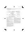
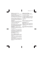
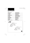
1923B (12lang)(cover) (’96. 4. 16)
Power Planer
Instruction Manual
F
Rabot
Manuel d’Instructions
D
Falzhobel
Betriebsanleitung
I
Pialla
Istruzioni d’Uso
Schaafmachine
Gebruiksaanwijzing
E
Cepillo
Manual de Instrucciones
P
Plaina
Manual de Instruço˜es
DK
Maskinhøvl
Brugsanvisning
S
Elhandhyvel
Bruksanvisning
N
Høvel
Bruksanvisning
SF
Höylä
Käyttöohje
GR
∏ÏÂÎÙÚÈ΋ ¶Ï¿ÓË
√‰ËÁ›Â˜ ÃÚ‹Ûˆ˜
GB
NL
1923B
N1923B
1923B (12lang)(illust)(’96. 4. 16)
1
2
3
4
5
6
7
8
2
1923B (12lang)(illust)(’96. 4. 16)
9
10
11
12
13
14
15
16
3
1923B (12lang)(illust)(’96. 4. 16)
17
18
19
20
21
22
23
24
4
1923B (12lang)(illust)(’96. 4. 16)
25
26
27
5
1923B/N1923B (Eng) (’97. 7. 8)
ENGLISH
1
2
3
4
5
6
7
8
9
0
q
w
e
r
t
y
u
Bolt
Drum
Planer blade
Drum cover
Adjust plate
Blade edge
Screws
Heel
Back side of gauge base
Inside edge of gauge plate
Gauge plate
Gauge base
Pan head screw
Planer blade locating lugs
Heel of adjust plate
Set plate
Inside flank of gauge plate
Explanation of general view
i
o
p
a
s
d
f
g
h
j
k
l
;
z
x
Mini planer blade
Hex. flange head bolt
Groove
Knob
Switch trigger
Lock button/
Lock-off button
Start
End
Blade edge
Cutting line
Screw
Edge fence
‘‘V’’ groove
Front base
Align the ‘‘V’’ groove with the
edge of the workpiece.
SPECIFICATIONS
Model
1923B/N1923B
Planing width ................................................. 82 mm
Planing depth ................................................... 1 mm
Shiplapping depth .......................................... 23 mm
No load speed (RPM) .................................... 16,000
Overall length ............................................... 293 mm
Net weight ....................................................... 2.9 kg
• Due to the continuing program of research and
development, the specifications herein are subject
to change without prior notice.
• Note: Specifications may differ from country to
country.
Power supply
The machine should be connected only to a power
supply of the same voltage as indicated on the
nameplate, and can only be operated on single-phase
AC supply. They are double-insulated in accordance
with European Standard and can, therefore, also be
used from sockets without earth wire.
Safety hints
For your own safety, please refer to enclosed Safety
instructions.
These symbols mean:
Read instruction manual.
DOUBLE INSULATION
c
v
b
n
m
,
.
/
¡
™
£
¢
∞
§
¶
Nozzle assembly
Chip cover screw
Chip cover
Fit pin on nozzle assembly
into this hole.
Sharpening holder
Wing nut
Blade (A)
Blade (B)
Side (C)
Side (D)
Chip cover
Makita vacuum cleaner
Limit mark
Screwdriver
Brush holder cap
ADDITIONAL SAFETY RULES
1. Rags, cloth, cord, string and the like should
never be left around the work area.
2. Avoid cutting nails. Inspect for and remove all
nails from the workpiece before operation.
3. Handle the blades very carefully.
4. Be sure the blade installation bolts are
securely tightened before operation.
5. Hold the machine firmly with both hands.
6. Keep hands away from rotating parts.
7. Before using the machine on an actual workpiece, let it run for a while. Watch for vibration
or wobbling that could indicate poor installation or a poorly balanced blade.
8. Make sure the blade is not contacting the
workpiece before the switch is turned on.
9. Wait until the blade attains full speed before
cutting.
10. Keep at least 200 mm away from the machine
at all times.
11. Always switch off and wait for the blades to
come to a complete stop before any adjusting.
12. Never stick your finger into the chip chute.
Chute may jam when cutting damp wood.
Clean out chips with a stick.
13. Do not leave the machine running. Operate the
machine only when hand-held.
14. When leaving the planer, switch off and set it
with the front base up on a wooden block, so
that the blades do not contact anything.
15. Always change both blades or covers on the
drum, otherwise the resulting imbalance will
cause vibration and shorten machine life.
16. Wait for complete run-down before putting the
machine aside.
17. Use only Makita blades specified in this
manual.
SAVE THESE INSTRUCTIONS.
6
1923B/N1923B (Eng) (’97. 7. 15)
OPERATING INSTRUCTIONS
Removing or installing planer blades
Important:
• Always be sure that machine is switched off and
unplugged before removing or installing the blade.
• Use the following planer blades.
Part Nos. 793004-6 793007-0 793322-2
*P-04226 *P04282 *P-04298
*820044-1 *820045-1 *820043-1
Blades with * mark are available in European countries only. Consult your dealer or the Makita Service
Center when purchasing blades.
For machine with standard planer blades
(Fig. 1, 3 & 4)
To remove the blades on the drum, unscrew the three
installation bolts with the socket wrench. The drum
cover comes off together with the blades.
To install the blades, first clean out all chips or foreign
matter adhering to the drum or blades. Use blades of
the same dimensions and weight, or drum
oscillation/vibration will result, causing poor planing
action and, eventually, machine breakdown.
Place the blade on the gauge base so that the blade
edge is perfectly flush with the inside edge of the
gauge plate. Place the adjust plate on the blade, then
simply press in the heel of the adjust plate flush with
the back side of the gauge base and tighten two
screws on the adjust plate. Now slip the heel of the
adjust plate into the drum groove, then fit the drum
cover on it. Tighten the three installation bolts evenly
and alternately with the socket wrench.
For machine with mini planer blades (Fig. 1, 5 & 6)
1. Remove the existing blade, if the machine has
been in use, carefully clean the drum surfaces and
the drum cover. To remove the blades on the
drum, unscrew the three installation bolts with the
socket wrench. The drum cover comes off
together with the blades.
2. To install the blades, loosely attach the adjust
plate to the set plate with the pan head screws
and set the mini planer blade on the gauge base
so that the cutting edge of the blade is perfectly
flush with the inside flank of the gauge plate.
3. Set the adjust plate/set plate on the gauge base
so that the planer blade locating lugs on the set
plate rest in the mini planer blade groove, then
press in the heel of the adjust plate flush with the
back side of the gauge base and tighten the pan
head screws.
4. It is important that the blade sits flush with the
inside flank of the gauge plate, the planer blade
locating lugs sit in the blade groove and the heel
of the adjust plate is flush with the back side of the
gauge base. Check this alignment carefully to
ensure uniform cutting.
5. Slip the heel of the adjust plate into the groove of
the drum.
6. Set the drum cover over the adjust plate/set plate
and screw in the three hex flange head bolts so
that a gap exists between the drum and the set
plate to slide the mini planer blade into position.
The blade will be positioned by the planer blade
locating lugs on the set plate.
7. The blade’s lengthwise adjustment will need to be
manually positioned so that the blade ends are
clear and equidistant from the housing on one
side and the metal bracket on the other.
8. Tighten the three hex flange head bolts (with the
socket wrench provided) and hand rotate the
drum to check clearances between the blade ends
and the machine body.
9. Check the three hex flange head bolts for final
tightness.
10. Repeat procedures 1 – 9 for other blade.
For shiplapping (Fig. 7)
The blade edge should be made to protrude outside
slightly (0.3 mm – 0.6 mm). Otherwise, nicks and
generally poor shiplapping results.
CAUTION:
Tighten the blade installation bolts carefully when
attaching the blades to the machine. A loose installation bolt can be dangerous. Always check to see they
are tightened securely.
7
1923B/N1923B (Eng) (’97. 7. 15)
For the correct planer blade setting
Your planing surface will end up rough and uneven, unless the blade is set properly and securely. The blade
must be mounted so that the cutting edge is absolutely level, that is, parallel to the surface of the rear base.
Below are some examples of proper and improper settings.
(A) Front base (Movable shoe)
(B) Rear base (Stationary shoe)
Correct setting
Although this side view cannot show
it, the edges of the blades run
perfectly parallel to the rear base
surface.
Nicks in surface
Cause: One or both blades fails to
have edge parallel to rear
base line.
Gouging at start
Gouging at end
Cause: One or both blade edges fails
to protrude enough in relation
to rear base line.
Cause: One or both blade edges
protrudes too far in relation to
rear base line.
Adjusting the depth of cut (Fig. 8)
Planing operation (Fig. 11)
Depth of cut may be adjusted by simply turning the
knob on the front of the machine.
First, rest the machine front base flat upon the
workpiece surface without the blades making any
contact. Switch on and wait until the blades attain full
speed. Then move the machine gently forward. Apply
pressure on the front of machine at the start of
planing, and at the back at the end of planing. Planing
will be easier if you incline the workpiece in stationary
fashion, so that you can plane somewhat downhill.
The speed and depth of cut determine the kind of
finish. The power planer keeps cutting at a speed that
will not result in jamming by chips. For rough cutting,
the depth of cut can be increased, while for a good
finish you should reduce the depth of cut and advance
the machine more slowly.
Switch action
CAUTION:
Before plugging in the machine, always check to see
that the switch trigger actuates properly and returns to
the ‘‘OFF’’ position when released.
For machine without lock button and lock-off
button (Fig. 9)
To start the machine, simply pull the trigger. Release
the trigger to stop.
For machine with lock button (Fig. 10)
To start the machine, simply pull the trigger. Release
the trigger to stop. For continuous operation, pull the
trigger and then push in the lock button. To stop the
machine from the locked position, pull the trigger fully,
then release it.
For machine with lock-off button (Fig. 10)
To prevent the trigger from being accidentally pulled,
a lock-off button is provided. To start the machine,
press the lock-off button and pull the trigger. Release
the trigger to stop.
8
1923B/N1923B (Eng) (’97. 7. 15)
Shiplapping (Fig. 12, 13, 14 & 15)
Connecting a vacuum cleaner
To make a stepped cut as shown in Fig. 12, use the
edge fence.
For European countries and areas (Fig. 24)
When you wish to perform clean planing operation,
connect a Makita vacuum cleaner to your machine as
shown in Fig. 24.
Draw a cutting line on the workpiece. Insert the edge
fence into the hole in the front of the machine. Align
the blade edge with the cutting line.
Adjust the edge fence until it comes in contact with the
side of the workpiece, then secure it by tightening the
screw.
You may wish to add to the length of the fence by
attaching an extra piece of wood. Convenient holes
are provided in the fence for this purpose, and also for
attaching an extension guide (optional accessory).
NOTE:
When planing, move the machine with the edge fence
flush with the side of the workpiece. Otherwise
uneven planing may result.
Max. shiplapping depth is 23 mm.
Chamfering (Fig. 16, 17 & 18)
To make a cut as shown in Fig. 16, align the ‘‘V’’
groove in the front base with the edge of the workpiece and plane it as shown in the Fig. 18.
Nozzle assembly (optional accessory)
(Fig. 19 & 20)
Use of the special nozzle assembly will minimize chip
scatter, making for a cleaner work area.
For other countries and areas
A nozzle and joint (optional accessories) are necessary to connect a Makita vacuum cleaner to your
machine. Consult a Makita catalogue or representative on the nozzle and joint.
MAINTENANCE
CAUTION:
Always be sure that the machine is switched off and
unplugged before carrying out any work on the
machine.
Replacement of carbon brushes
(Fig. 25, 26 & 27)
Replace carbon brushes when they are worn down to
the limit mark. First, remove the chip cover and then
replace the carbon brushes. Both identical carbon
brushes should be replaced at the same time.
To maintain product safety and reliability, repairs,
maintenance or adjustment should be carried out by
Makita Authorized Service Center.
The nozzle assembly may be attached after the chip
cover on the machine body is removed. When slipping on the assembly, fit the pin on it into the rear
cover hole. Use the chip cover screws to fasten it in
place.
Sharpening the planer blades
(Fig. 21, 22 & 23)
For standard blades only
Always keep your blades sharp for the best performance possible. Use the sharpening holder to
remove nicks and produce a fine edge.
First, loosen the two wing nuts on the holder and
insert the blades (A) and (B), so that they contact the
sides (C) and (D). Then tighten the wing nuts.
Immerse the dressing stone in water for 2 or 3
minutes before sharpening. Hold the holder so that
the blades both contact the dressing stone for simultaneous sharpening at the same angle.
9
1923B (Nl) (’100. 6. 26)
NEDERLANDS
1
2
3
4
5
6
7
8
9
0
q
w
e
r
t
y
u
Verklaring van algemene gegevens
Bout
Schaafblok
Schaafmes
Afdekplaat van schaafblok
Afstelplaat
Mesrand
Schroeven
Hiel
Zijkant van mal
Binnenrand kaliberplaat
Kaliberplaat
Kalibervoet
Kruiskopschroef
Vastzetnokjes schaafmes
Hiel van afstelplaat
Aanzetplaat
Binnenkant van kaliberplaat
i
o
p
a
s
d
f
g
h
j
k
l
;
z
x
Mini schaafmes
Zeskante bout
Groef
Knop
Trekkerschakelaar
Vergrendelknop/
Ontgrendelknop
Start
Einde
Mesrand
Snijlijn
Schroef
Breedtegeleider
‘‘V’’ groef
Voorste voetstuk
Zorg dat de ‘‘V’’ groef op de
rand van het werkstuk blijft.
TECHNISCHE GEGEVENS
Model
1923B/N1923B
Schaafbreedte ................................................ 82 mm
Max. schaafdiepte ............................................ 1 mm
Sponningdiepte .............................................. 23 mm
Toerental onbelast/min. .................................. 16 000
Totale lengte ................................................ 293 mm
Netto gewicht .................................................. 2,9 kg
• In verband met ononderbroken research en
ontwikkeling behouden wij ons het recht voor bovenstaande technische gegevens te wijzigen zonder
voorafgaande kennisgeving.
• Opmerking: De technische gegevens kunnen van
land tot land verschillen.
Stroomvoorziening
De machine mag alleen worden aangesloten op een
stroombron van hetzelfde voltage als aangegeven op de
naamplaat, en kan alleen op enkel-fase wisselstroom
worden gebruikt. De machine is dubbel-geı¨soleerd volgens de Europese standaard en kan derhalve ook op
een niet-geaard stopcontact worden aangesloten.
Veiligheidswenken
Voor uw veiligheid dient u de bijgevoegde Veiligheidsvoorschriften nauwkeurig op te volgen.
Deze symbolen betekenen:
Lees de gebruiksaanwijzing.
DUBBELE ISOLATIE
AANVULLENDE
VEILIGHEIDSVOORSCHRIFTEN
1. Lompen, doeken, touwen en soortgelijke prullen dienen nooit in het werkgebied achtergelaten te worden.
2. Zorg dat het gereedschap nooit in kontakt
komt met spijkers. Verwijder alvorens te
schaven eventuele spijkers van het werkstuk.
22
c
v
b
n
m
,
.
/
¡
™
£
¢
∞
§
¶
Spaanafvoer
Schroefvoor Spaanafvoer
Spaanafvoer
Steek de pen op de
Spaanafvoer
Aanscherphouder
Vleugelmoer
Mes (A)
Mes (B)
Zijkant (C)
Zijkant (D)
Spaanafvoer
Makita stofzuiger
Limiet markering
Schroevedraaier
Kap van de koolborstelhouder
3. Wees zeer voorzichtig met de messen.
4. Kontroleer alvorens te schaven of de bevestigingsbouten van de messen stevig vastgedraaid zijn.
5. Houd het gereedschap met beide handen
stevig vast.
6. Houd uw handen uit de buurt van de bewegende delen.
7. Alvorens het gereedschap op een werkstuk te
gebruiken, laat u het een tijdje draaien. Onderzoek het op vibraties of schommelende
bewegingen die op een onjuiste installatie of
onjuist gebalanceerde messen kunnen wijzen.
8. Zorg dat de messen niet in aanraking zijn met
het werkstuk als u het gereedschap in wilt
schakelen.
9. Wacht alvorens te schaven tot de messen op
volle snelheid draaien.
10. Zorg dat u het gereedschap ten alle tijde op
een afstand houdt van minstens 200 mm.
11. Alvorens iets bij te stellen dient u altijd het
gereedschap uit te schakelen en te wachten
totdat de messen volledig tot stilstand zijn
gekomen.
12. Steek uw vinger nooit in de spaanafvoer. De
spanen kunnen erin klem raken als u nat hout
schaaft. Verwijder in dit geval de spanen met
een stukje hout.
13. Schakel altijd uit als u het gereedschap niet
gebruikt. Schakel het gereedschap alleen in
als u het in handen houdt.
14. Wanneer u het gereedschap achterlaat,
schakel het uit en zet het op een plankje met
het voorstuk naar boven gericht zodat de messen niets aanraken.
1923B (Nl) (’100. 6. 26)
15. Vervang altijd gelijktijdig beide messen en
klemplaten, aangezien anders het resulterende verlies van evenwicht trillingen kunnen
veroorzaken, waardoor de gebruiksduur van
het gereedschap verkort kan worden.
16. Wacht totdat de messen volledig tot stilstand
zijn gekomen, alvorens de machine opzij te
zetten.
17. Gebruik alleen Makita messen die in deze
gebruiksaanwijzing zijn gespecificeerd.
BEWAAR DEZE VOORSCHRIFTEN.
BEDIENINGSVOORSCHRIFTEN
Verwijderen of installeren van de
schaafmessen
Belangrijk:
• Controleer altijd of de machine is uitgeschakeld en
het netsnoer uit het stopcontact is verwijderd, alvorens de messen te verwijderen of te installeren.
• Gebruik de volgende schaafmessen.
Onderdeelnr. 793004-6 793007-0 793322-2
*P-04226 *P-04282 *P-04298
*820044-1 *820045-1 *820043-1
De met * gemarkeerde messen zijn alleen in
Europese landen verkrijgbaar. Raadpleeg uw
dealer of het Makita Service-centrum wanneer u
messen wilt kopen.
Voor machines met standaard-schaafmessen
(Fig. 1, 3 en 4)
Om de messen van het schaafblok te verwijderen,
draait u met de soksleutel de drie bevestigingsbouten
los. De afdekplaat kunt u dan tegelijk met de messen
verwijderen.
Alvorens de nieuwe messen te installeren, verwijder
eerst alle schaafkrullen of verontreinigingen van het
schaafblok of de messen. Gebruik messen van
dezelfde afmetingen en hetzelfde gewicht, omdat het
schaafblok anders zal slingeren of trillen, zodat de
machine niet gelijk zal schaven en eventueel defect
kan raken.
Plaats het mes zodanig op de kalibervoet, dat de
scherpe kant van het mes volkomen vlak ligt met de
binnenrand van de kaliberplaat. Plaats de afstelplaat
op het mes, druk dan de hiel van de afstelplaat naar
beneden totdat deze vlak ligt met de kalibervoet, en
draai dan de twee schroeven op de afstelplaat vast.
Schuif nu de hiel van de afstelplaat in de groef van het
schaafblok, en plaats dan de afdekplaat van het
schaafblok erop. Draai de drie bevestigingsbouten
gelijkmatig en afwisselend vast met behulp van de
soksleutel.
Voor machines met mini-schaafmessen
(Fig. 1, 5 en 6)
1. Indien de machine pas is gebruikt, verwijdert u
eerst het gebruikte schaafmes. Maak vervolgens
de oppervlakken en de afdekplaat van het schaafblok grondig schoon. Om de messen van het
schaafblok te verwijderen, draait u met de soksleutel de drie bevestigingsbouten los. De afdekplaat kunt u dan tegelijk met de messen verwijderen.
2. Om de nieuwe messen te installeren, bevestig de
afstelplaat losjes op de klemplaat met behulp van
de kruiskopschroeven en plaats dan het minischaafmes zodanig op de kalibervoet, dat de
scherpe kant van het mes volkomen vlak ligt met
de binnenrand van de kaliberplaat.
3. Plaats de afstelplaat/aanzetplaat op de mal zodat
de vastzetnokjes op de aanzetplaat in de groef
van het mini schaafmes rusten. Druk vervolgens
de zool van afstelplaat totdat deze gelijk komt met
de zijkant van de mal en draai de schroeven vast.
4. Het is belangrijk dat het schaafmes gelijk en vlak
tegen de binnenkant van de malplaat aanligt, dat
de vastzetnokjes in de groef van het schaafmes
rusten en dat de zool van de afstelplaat volkommen gelijk is met de zijkant van de mal. Kontroleer
of dit zo is, aangezien het gereedschap anders
niet gelijk kan schaven.
5. Schuif de zool van de afstelplaat in de groef van
het schaafblok.
6. Plaats de afdekplaat van het schaafblok op de
afstelplaat/aanzetplaat en draai de drie zeskantbouten vast, echter zo dat er een spleet blijft
bestaan tussen het schaafblok en de aanzetplaat
om het mini schaafmes op z’n plaats te schuiven.
Door de vastzetnokjes zal het mes op de aanzetplaat vastgehouden worden.
7. De lengte van het mes dient met de hand zo te
worden bijgesteld dat de uiteinden van het mes op
gelijke afstand van de behuizing aan de ene kant
en de metalen beugel aan de andere kant uitsteken.
8. Draai de drie zeskantbouten met de bijgeleverde
soksleutel vast. Kontroleer of het mes even ver
van het schaafblok uitsteken.
9. Kontroleer of de drie zeskante bouten goed zijn
aangetrokken.
10. Herhaal de procedure, vanaf stap 1 tot en met 9
voor het monteren van een ander schaafblad.
Voor rabatten (Fig. 7)
Zorg ervoor dat de scherpe rand van het mes een
beetje (0,3 mm – 0,6 mm) uitsteekt. Indien dit wordt
verzuimd, zal het schaven resulteren in kerven en
slecht rabatten. (Sponning schaven)
LET OP:
Trek de bevestigingsbouten zorgvuldig aan wanneer
u de messen aan de machine bevestigt. Een losse
bevestigingsbout kan gevaar opleveren. Controleer
altijd of de bouten goed zijn vastgedraaid.
23
1923B (Nl) (’100. 6. 23)
Voor de juiste mesinstelling
Uw schaafvlak zal ruw en ongelijk worden, indien het mes niet correct is ingesteld. Het mes moet dusdanig
gemonteerd worden dat de zijkant absoluut gelijk ligt ofwel parallel met het vlak van de achterzool.
Onderstaand enkele voorbeelden van juiste en onjuiste instellingen.
(A) Voor zool (beweegbaar)
(B) Achterzool (vast)
Correcte instelling
Ofschoon dit zijaanzicht het niet
toont, draaien de snijkanten van het
mes perfect parallel met de
achterzool.
Happen in het oppervlak
Oorzaak: Eén van beide messen
staat niet parallel ingesteld
met achterzool.
Gutsen bij het
begin
Gutsen het eind
Oorzaak: Eén van beide messen
steekt niet voldoende uit in
relatie tot achterzool.
Oorzaak: Eén van beide messen
steekt te ver uit in relatie tot
achterzool.
Instellen van schaafdiepte (Fig. 8)
Schaven (Fig. 11)
De schaafdiepte is heel eenvoudig in te stellen door
de knop voor op het gereedschap te verdraaien.
Leg eerst het voorste zoolvlak plat op het oppervlak
van het werkstuk, zonder dat de messen nog iets
aanraken. Schakel het gereedschap in en wacht
totdat de messen op volle snelheid draaien. Hierna
beweegt u het gereedschap langzaam vooruit. Oefen
druk uit op het voorste gedeelte van het gereedschap
als u begint te schaven en op het achterste gedeelte
als het einde nadert.
Het schaven gaat gemakkelijker als u het werkstuk
een beetje schuin houdt, zodat u schaaft met het
gereedschap iets naar beneden gericht.
Werking van de trekkerschakelaar
LET OP:
Alvorens de machine op netstroom aan te sluiten,
dient u altijd te controleren of de trekkerschakelaar
behoorlijk werkt en bij het loslaten naar de ‘‘OFF’’
positie terugkeert.
Voor machines zonder vergrendelknop en
ontgrendelknop (Fig. 9)
Om de machine in te schakelen, drukt u gewoon de
trekkerschakelaar in. Laat de schakelaar los om de
machine uit te schakelen.
Voor machines met een vergrendelknop (Fig. 10)
Om de machine in te schakelen, drukt u gewoon de
trekkerschakelaar in. Laat de schakelaar los om de
machine uit te schakelen. Voor continu gebruik, eerst
de trekkerschakelaar en dan de vergrendelknop
indrukken. Om de machine vanuit de vergrendelde
stand te stoppen, de trekkerschakelaar helemaal
indrukken en deze dan loslaten.
Voor machines met een ontgrendelknop (Fig. 10)
Een ontgrendelknop is voorzien om te voorkomen dat
de trekkerschakelaar per toeval wordt ingedrukt. Om
de machine te starten, druk de ontgrendelknop in en
druk dan de trekkerschakelaar in. Om de machine te
stoppen, de trekkerschakelaar loslaten.
24
De snelheid waarmee u schaaft en de schaaftdiepte
bepalen het resultaat. De snelheid van het gereedschap zelf is zodanig dat de spanen nooit klemraken.
Voor ruw schaven kunt u de schaafdiepte vermeerderen, terwijl voor een goede afwerking de
schaafdiepte verminderd moet worden en het gereedschap langzamer vooruitbewogen dient te worden.
1923B (Nl) (’100. 6. 26)
Rabatten (Fig. 12, 13, 14 en 15)
Aansluiten van een stofzuiger
Gebruik de zijkantgeleider voor zijdelings schaven
zoals afgebeeld in Fig. 12.
Voor Europese landen en gebieden (Fig. 24)
Voor schoon schaven sluit u een Makita-stofzuiger
aan op uw machine (zie Fig. 24).
Breng op het werkstuk de snijlijn aan. Steek de
zijkantgeleider in het gaatje aan de voorkant van het
gereedschap. Zet het mes op de snijlijn.
Stel de zijkantgeleider zodanig in dat deze volledig
kontakt maakt met de zijkant van het werkstuk. Zet de
geleider vervolgens vast door middel van de schroef.
Soms is het wenselijk voor betere geleiding van het
gereedschap de geleider te verbreden. Dit kunt u
doen door een lat te bevestigen. De geleider is voor
dit doel voorzien van gaten, die ook kunnen dienen
voor het bevestigen van een verlengstuk (los verkrijgbaar toebehoren).
OPMERKING:
U dient tijdens het schaven de zijkantgeleider steeds
tegen de zijkant van het werkstuk te houden, aangezien anders de snede ongelijkmatig wordt.
De maximale sponningsdiepte is 23 mm.
Afschuinen (Fig. 16, 17 en 18)
Voor het maken van sneden zoals afgebeeld in
Fig. 16, zorg ervoor dat de ‘‘V’’ groef in het voorste
voetstuk van de machine op de rand van het werkstuk
rust, en schaaf dan zoals afgebeeld in Fig. 18.
Spaanafvoer (los verkrijgbaar toebehoren)
(Fig. 19 en 20)
Door gebruikmaking van de speciale spaanafvoer kan
het rondvliegen van schaafkrullen tot een minimum
worden beperkt. Hierdoor zal de werkruimte er
schoner gaan uitzien.
Voor andere landen en gebieden
Om een Makita-stofzuiger aan uw machine te bevestigen, hebt u een verbindingsstuk en scharnierstuk
(los verkrijgbare accessoires) nodig. Voor het
verbindingsstuk en scharnierstuk dient u een catalogus of vertegenwoordiger van Makita te raadplegen.
ONDERHOUD
LET OP:
Zorg er altijd voor dat de machine is uitgeschakeld en
de stekker uit het stopcontact is verwijderd alvorens
werken aan de machine uit te voeren.
Vervangen van koolborstels
(Fig. 25, 26 en 27)
Vervang de koolborstels wanneer deze tot aan de
limietmarkering zijn versleten. Verwijder eerst de
schaafkrulkap en vervang dan de koolborstels. Vervang altijd beide koolsborstels gelijktijdig door gelijksoortige koolborstels.
Opdat het gereedschap veilig en betrouwbaar blijft,
dienen alle reparaties, onderhoud of afstellingen te
worden uitgevoerd bij een erkend Makita service
centrum.
De spaanafvoer kan worden bevestigd nadat de
standaard spaanafvoer van de machine is verwijderd.
Bij het bevestigen van de spaanafvoer dient u de
daarop aanwezige pen in het achterste gat van het
machinehuis te steken. Gebruik dezelfde schroeven
om de spaanafvoer te bevestigen.
Aanscherpen van de schaafmessen
(Fig. 21, 22 en 23)
Alleen voor standaard-schaafmessen
Houd uw schaafmessen altijd scherp om de best
mogelijke resultaten te krijgen. Gebruik de aanscherphouder. Om bramen te verwijderen of de beitels aan
te scherpen.
Draai eerst de twee vleugelmoeren op de houder los
en steek messen (A) en (B) erin zodat deze met
zijkanten (C) en (D) in aanraking komen. Draai dan de
twee vleugelmoeren vast.
Dompel de wetsteen voor 2 of 3 minuten in water
alvorens aan te scherpen. Houd de aanscherphouder
zodanig, dat beide messen met de wetsteen in aanraking komen voor gelijktijdig aanscherpen onder
dezelfde hoek.
25