1
TMS320x280x, 2801x, 2804x High Resolution
Pulse Width Modulator (HRPWM)
Reference Guide
Literature Number: SPRU924F
April 2005 – Revised October 2011
2
SPRU924F – April 2005 – Revised October 2011
Submit Documentation Feedback
Copyright © 2005–2011, Texas Instruments Incorporated
Contents
Preface ....................................................................................................................................... 5
1
Introduction ........................................................................................................................ 7
2
Operational Description of HRPWM ....................................................................................... 9
................................................................................ 10
.............................................................................................. 11
2.3
Principle of Operation ................................................................................................. 12
2.4
Scale Factor Optimizing Software (SFO) ........................................................................... 18
2.5
HRPWM Examples Using Optimized Assembly Code ............................................................ 23
3
HRPWM Register Descriptions ............................................................................................ 29
3.1
Register Summary ..................................................................................................... 29
3.2
Registers and Field Descriptions .................................................................................... 30
Appendix A SFO Library Software - SFO_TI_Build_V5.lib ............................................................... 33
A.1
SFO Library Version Comparison .................................................................................. 33
A.2
Software Usage ....................................................................................................... 36
Appendix B Revision History ...................................................................................................... 41
2.1
Controlling the HRPWM Capabilities
2.2
Configuring the HRPWM
SPRU924F – April 2005 – Revised October 2011
Submit Documentation Feedback
Copyright © 2005–2011, Texas Instruments Incorporated
Table of Contents
3
www.ti.com
List of Figures
1
Resolution Calculations for Conventionally Generated PWM ......................................................... 7
2
Operating Logic Using MEP ............................................................................................... 9
3
HRPWM Extension Registers and Memory Configuration ........................................................... 10
4
HRPWM System Interface
5
Required PWM Waveform for a Requested Duty = 40.5% .......................................................... 13
6
Low % Duty Cycle Range Limitation Example When PWM Frequency = 1 MHz
16
7
High % Duty Cycle Range Limitation Example when PWM Frequency = 1 MHz
18
8
9
10
11
12
13
14
...............................................................................................
................................
................................
Simple Buck Controlled Converter Using a Single PWM ............................................................
PWM Waveform Generated for Simple Buck Controlled Converter ................................................
Simple Reconstruction Filter for a PWM Based DAC ................................................................
PWM Waveform Generated for the PWM DAC Function ............................................................
HRPWM Configuration Register (HRCNFG) ...........................................................................
Counter Compare A High Resolution Register (CMPAHR) ..........................................................
TB Phase High Resolution Register (TBPHSHR) .....................................................................
11
24
24
26
26
30
30
30
List of Tables
1
Resolution for PWM and HRPWM ........................................................................................ 7
2
HRPWM Registers ........................................................................................................ 10
3
Relationship Between MEP Steps, PWM Frequency and Resolution .............................................. 12
4
CMPA vs Duty (left), and [CMPA:CMPAHR] vs Duty (right) ......................................................... 14
5
Duty Cycle Range Limitation for 3 and 6 SYSCLK/TBCLK Cycles ................................................. 17
6
SFO Library Routines ..................................................................................................... 18
7
Factor Values .............................................................................................................. 21
8
Register Descriptions ..................................................................................................... 29
9
HRPWM Configuration Register (HRCNFG) Field Descriptions .................................................... 30
10
Counter Compare A High Resolution Register (CMPAHR) Field Descriptions
30
11
TB Phase High Resolution Register (TBPHSHR) Field Descriptions
31
12
13
14
15
4
...................................
..............................................
SFO Library Version Comparison .......................................................................................
SFO V5 Library Routines .................................................................................................
Software Functions ........................................................................................................
Technical Changes in the Current Revision ...........................................................................
List of Figures
33
34
36
41
SPRU924F – April 2005 – Revised October 2011
Submit Documentation Feedback
Copyright © 2005–2011, Texas Instruments Incorporated
Preface
SPRU924F – April 2005 – Revised October 2011
Read This First
About This Manual
This document describes the operation of the high-resolution extension to the pulse width modulator
(HRPWM) . The HRPWM module described in this reference guide is a Type 0 HRPWM. See the
TMS320x28xx, 28xxx DSP Peripheral Reference Guide (SPRU566) for a list of all devices with an
HRPWM module of the same type, to determine the differences between types, and for a list of
device-specific differences within a type.
Notational Conventions
This document uses the following conventions.
• Hexadecimal numbers are shown with the suffix h. For example, the following number is 40
hexadecimal (decimal 64): 40h.
• Registers in this document are shown in figures and described in tables.
– Each register figure shows a rectangle divided into fields that represent the fields of the register.
Each field is labeled with its bit name, its beginning and ending bit numbers above, and its
read/write properties below. A legend explains the notation used for the properties.
– Reserved bits in a register figure designate a bit that is used for future device expansion.
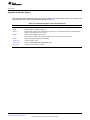
Related Documentation From Texas Instruments
The following documents describe the C2000™ devices and related support tools. Copies of these
documents are available on the Internet at www.ti.com. Tip: Enter the literature number in the search box
provided at www.ti.com.
The current documentation that describes the devices, related peripherals, and other technical collateral,
is available in the C2000 DSP product folder at: www.ti.com/c2000.
Data Manuals—
SPRS230 — TMS320F2809, F2808, F2806, F2802, F2801, C2802, C2801, and F2801x DSPs Data
Manual contains the pinout, signal descriptions, as well as electrical and timing specifications for
the F280x devices.
SPRZ171 — TMS320F280x, TMS320C280x, and TMS320F2801x DSC Silicon Errata
describes the advisories and usage notes for different versions of silicon.
SPRS357 — TMS320F28044 Digital Signal Processor Data Manual contains the pinout, signal
descriptions, as well as electrical and timing specifications for the F28044 device.
SPRZ255 — TMS320F28044 DSP Silicon Errata
describes the advisories and usage notes for different versions of silicon.
CPU User's Guides—
SPRU430 — TMS320C28x CPU and Instruction Set Reference Guide describes the central processing
unit (CPU) and the assembly language instructions of the TMS320C28x fixed-point digital signal
processors (DSPs). It also describes emulation features available on these DSPs.
SPRU712 — TMS320x280x, 2801x, 2804x DSP System Control and Interrupts Reference Guide
describes the various interrupts and system control features of the 280x digital signal processors
(DSPs).
Peripheral Guides —
SPRU924F – April 2005 – Revised October 2011
Submit Documentation Feedback
Copyright © 2005–2011, Texas Instruments Incorporated
Preface
5
Related Documentation From Texas Instruments
www.ti.com
SPRU566 — TMS320x28xx, 28xxx DSP Peripheral Reference Guide describes the peripheral
reference guides of the 28x digital signal processors (DSPs).
SPRU716 — TMS320x280x, 2801x, 2804x DSP Analog-to-Digital Converter (ADC) Reference Guide
describes how to configure and use the on-chip ADC module, which is a 12-bit pipelined ADC.
SPRU791 — TMS320x280x, 2801x, 2804x Enhanced Pulse Width Modulator (ePWM) Module
Reference Guide describes the main areas of the enhanced pulse width modulator that include
digital motor control, switch mode power supply control, UPS (uninterruptible power supplies), and
other forms of power conversion
SPRU790 — TMS320x280x, 2801x, 2804x Enhanced Quadrature Encoder Pulse (eQEP) Module
Reference Guide describes the eQEP module, which is used for interfacing with a linear or rotary
incremental encoder to get position, direction, and speed information from a rotating machine in
high performance motion and position control systems. It includes the module description and
registers
SPRU807 — TMS320x280x, 2801x, 2804x Enhanced Capture (eCAP) Module Reference Guide
describes the enhanced capture module. It includes the module description and registers.
SPRU924 — TMS320x280x, 2801x, 2804x High-Resolution Pulse Width Modulator Reference Guide
describes the operation of the high-resolution extension to the pulse width modulator (HRPWM).
SPRUEU0 — TMS320x280x/2801x Enhanced Controller Area Network (eCAN) Reference Guide
describes the enhanced controller area network (eCAN) on the x280x and x2801x devices.
SPRUFK7 — TMS320x280x, 2801x, 2804x Serial Communication Interface (SCI) Reference Guide
describes the features and operation of the serial communication interface (SCI) module that is
available on the TMS320x280x, 2801x, 2804x devices.
SPRUG72 — TMS320x280x, 2801x, 2804x Serial Peripheral Interface Reference Guide describes how
the serial peripheral interface works.
SPRU721 — TMS320x28xx, 28xxx Inter-Integrated Circuit (I2C) Module Reference Guide describes
the features and operation of the inter-integrated circuit (I2C) module.
SPRU722 — TMS320x280x, 2801x, 2804x Boot ROM Reference Guide describes the purpose and
features of the bootloader (factory-programmed boot-loading software). It also describes other
contents of the device on-chip boot ROM and identifies where all of the information is located within
that memory.
Tools Guides—
SPRU513 — TMS320C28x Assembly Language Tools v5.0.0 User's Guide describes the assembly
language tools (assembler and other tools used to develop assembly language code), assembler
directives, macros, common object file format, and symbolic debugging directives for the
TMS320C28x device.
SPRU514 — TMS320C28x Optimizing C/C++ Compiler v5.0.0 User's Guide describes the
TMS320C28x™ C/C++ compiler. This compiler accepts ANSI standard C/C++ source code and
produces TMS320 DSP assembly language source code for the TMS320C28x device.
SPRU608 — TMS320C28x Instruction Set Simulator Technical Overview describes the simulator,
available within the Code Composer Studio for TMS320C2000 IDE, that simulates the instruction
set of the C28x™ core.
SPRU625 — TMS320C28x DSP/BIOS 5.32 Application Programming Interface (API) Reference
Guide describes development using DSP/BIOS.
C2000, TMS320C28x, C28x are trademarks of Texas Instruments.
6
Read This First
SPRU924F – April 2005 – Revised October 2011
Submit Documentation Feedback
Copyright © 2005–2011, Texas Instruments Incorporated
Reference Guide
SPRU924F – April 2005 – Revised October 2011
High-Resolution Pulse Width Modulator (HRPWM)
This document is used in conjunction with the device-specific Enhanced Pulse Width Modulator (ePWM)
Module Reference Guide.
The HRPWM module extends the time resolution capabilities of the conventionally derived digital pulse
width modulator (PWM). HRPWM is typically used when PWM resolution falls below ~ 9-10 bits. This
occurs at PWM frequencies greater than ~200 kHz when using a CPU/system clock of 100 MHz. The key
features of HRPWM are:
• Extended time resolution capability
• Used in both duty cycle and phase-shift control methods
• Finer time granularity control or edge positioning using extensions to the Compare A and Phase
registers
• Implemented using the A signal path of PWM, i.e., on the EPWMxA output. EPWMxB output has
conventional PWM capabilities
• Self-check diagnostics software mode to check if the micro edge positioner (MEP) logic is running
optimally
1
Introduction
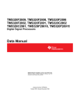
The ePWM peripheral is used to perform a function that is mathematically equivalent to a digital-to-analog
converter (DAC). As shown in Figure 1, where TSYSCLKOUT = 10 ns (i.e. 100 MHz clock), the effective
resolution for conventionally generated PWM is a function of PWM frequency (or period) and system clock
frequency.
Figure 1. Resolution Calculations for Conventionally Generated PWM
TPWM
PWM resolution (%) = FPWM/FSYSCLKOUT x 100%
PWM resolution (bits) = Log2 (TPWM/TSYSCLKOUT)
PWM
t
TSYSCLK
If the required PWM operating frequency does not offer sufficient resolution in PWM mode, you may want
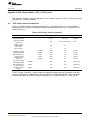
to consider HRPWM. As an example of improved performance offered by HRPWM, Table 1 shows
resolution in bits for various PWM frequencies. These values assume a 100 MHz SYSCLK frequency and
a MEP step size of 180 ps. See the device-specific datasheet for typical and maximum performance
specifications for the MEP.
Table 1. Resolution for PWM and HRPWM
PWM Freq
(kHz)
Regular Resolution (PWM)
High Resolution (HRPWM)
Bits
%
Bits
%
20
12.3
0.0
18.1
0.000
50
11.0
0.0
16.8
0.001
100
10.0
0.1
15.8
0.002
SPRU924F – April 2005 – Revised October 2011
Submit Documentation Feedback
High-Resolution Pulse Width Modulator (HRPWM)
Copyright © 2005–2011, Texas Instruments Incorporated
7
Introduction
www.ti.com
Table 1. Resolution for PWM and HRPWM (continued)
PWM Freq
(kHz)
Regular Resolution (PWM)
High Resolution (HRPWM)
Bits
%
Bits
%
150
9.4
0.2
15.2
0.003
200
9.0
0.2
14.8
0.004
250
8.6
0.3
14.4
0.005
500
7.6
0.5
13.8
0.007
1000
6.6
1.0
12.4
0.018
1500
6.1
1.5
11.9
0.027
2000
5.6
2.0
11.4
0.036
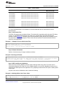
Although each application may differ, typical low frequency PWM operation (below 250 kHz) may not
require HRPWM. HRPWM capability is most useful for high frequency PWM requirements of power
conversion topologies such as:
• Single-phase buck, boost, and flyback
• Multi-phase buck, boost, and flyback
• Phase-shifted full bridge
• Direct modulation of D-Class power amplifiers
8
High-Resolution Pulse Width Modulator (HRPWM)
SPRU924F – April 2005 – Revised October 2011
Submit Documentation Feedback
Copyright © 2005–2011, Texas Instruments Incorporated
Operational Description of HRPWM
www.ti.com
2
Operational Description of HRPWM
The HRPWM is based on micro edge positioner (MEP) technology. MEP logic is capable of positioning an
edge very finely by sub-dividing one coarse system clock of a conventional PWM generator. The time step
accuracy is on the order of 150 ps. See the device-specific data sheet for the typical MEP step size on a
particular device. The HRPWM also has a self-check software diagnostics mode to check if the MEP logic
is running optimally, under all operating conditions. Details on software diagnostics and functions are in
Section 2.4.
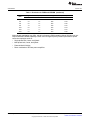
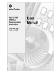
Figure 2 shows the relationship between one coarse system clock and edge position in terms of MEP
steps, which are controlled via an 8-bit field in the Compare A extension register (CMPAHR).
Figure 2. Operating Logic Using MEP
[
+1.5 ]
For MEP range and rounding adjustment (0x0180 in Q8 format)
To generate an HRPWM waveform, configure the TBM, CCM, and AQM registers as you would to
generate a conventional PWM of a given frequency and polarity. The HRPWM works together with the
TBM, CCM, and AQM registers to extend edge resolution, and should be configured accordingly. Although
many programming combinations are possible, only a few are needed and practical. These methods are
described in Section 2.5.
Registers discussed but not found in this document can be seen in the device-specific Enhanced Pulse
Width Modulator (ePWM) Module Reference Guide.
The HRPWM operation is controlled and monitored using the following registers:
SPRU924F – April 2005 – Revised October 2011
Submit Documentation Feedback
High-Resolution Pulse Width Modulator (HRPWM)
Copyright © 2005–2011, Texas Instruments Incorporated
9
Operational Description of HRPWM
www.ti.com
Table 2. HRPWM Registers
mnemonic
Address Offset
TBPHSHR
0x0002
No
Extension Register for HRPWM Phase (8 bits)
CMPAHR
0x0008
Yes
Extension Register for HRPWM Duty (8 bits)
HRCNFG (1)
0x0020
No
HRPWM Configuration Register
(1)
2.1
Shadowed
Description
This register is EALLOW protected.
Controlling the HRPWM Capabilities
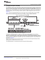
The MEP of the HRPWM is controlled by two extension registers, each 8-bits wide. These two HRPWM
registers are concatenated with the 16-bit TBPHS and CMPA registers used to control PWM operation.
• TBPHSHR - Time Base Phase High Resolution Register
• CMPAHR - Counter Compare A High Resolution Register
Figure 3. HRPWM Extension Registers and Memory Configuration
0x0002
TBPHSHR (8) Reserved (8)
0x0003
TBPHS (16)
31
16 15
TBPHS (16)
8 7
0
TBPHSHR (8) Reserved (8)
Single 32 bit write
0x0008
CMPAHR (8)
Reserved (8)
31
16 15
CMPA (16)
0x0009
8 7
CMPAHR (8)
0
Reserved (8)
CMPA (16)
Single 32 bit write
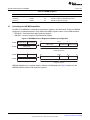
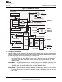
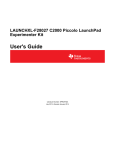
HRPWM capabilities are controlled using the Channel A PWM signal path. Figure 4 shows how the
HRPWM interfaces with the 8-bit extension registers.
10
High-Resolution Pulse Width Modulator (HRPWM)
SPRU924F – April 2005 – Revised October 2011
Submit Documentation Feedback
Copyright © 2005–2011, Texas Instruments Incorporated
Operational Description of HRPWM
www.ti.com
Figure 4. HRPWM System Interface
Time−base (TB)
Sync
in/out
select
Mux
CTR=ZERO
CTR=CMPB
Disabled
TBPRD shadow (16)
TBPRD active (16)
CTR=PRD
EPWMxSYNCO
TBCTL[SYNCOSEL]
TBCTL[PHSEN]
EPWMxSYNCI
Counter
up/down
(16 bit)
CTR=ZERO
CTR_Dir
TBCNT
active (16)
TBPHSHR (8)
16
8
TBPHS active (24)
Phase
control
Counter compare (CC)
CTR=CMPA
CMPAHR (8)
16
TBCTL[SWFSYNC]
(software forced sync)
Action
qualifier
(AQ)
CTR = PRD
CTR = ZERO
CTR = CMPA
CTR = CMPB
CTR_Dir
8
Event
trigger
and
interrupt
(ET)
EPWMxINT
EPWMxSOCA
EPWMxSOCB
HiRes PWM (HRPWM)
CMPA active (24)
EPWMA
EPWMxAO
CMPA shadow (24)
CTR=CMPB
Dead
band
(DB)
16
PWM
chopper
(PC)
EPWMB
EPWMxBO
CMPB active (16)
EPWMxTZINT
CMPB shadow (16)
2.2
Trip
zone
(TZ)
CTR = ZERO
TZ1 to TZ6
Configuring the HRPWM
Once the ePWM has been configured to provide conventional PWM of a given frequency and polarity, the
HRPWM is configured by programming the HRCNFG register located at offset address 20h. This register
provides configuration options for the following key operating modes :
Edge Mode — The MEP can be programmed to provide precise position control on the rising edge (RE),
falling edge (FE) or both edges (BE) at the same time. FE and RE are used for power topologies
requiring duty cycle control, while BE is used for topologies requiring phase shifting, e.g., phase
shifted full bridge.
Control Mode — The MEP is programmed to be controlled either from the CMPAHR register (duty cycle
control) or the TBPHSHR register (phase control). RE or FE control mode should be used with
CMPAHR register. BE control mode should be used with TBPHSHR register.
Shadow Mode — This mode provides the same shadowing (double buffering) option as in regular PWM
mode. This option is valid only when operating from the CMPAHR register and should be chosen to
be the same as the regular load option for the CMPA register. If TBPHSHR is used, then this option
has no effect.
SPRU924F – April 2005 – Revised October 2011
Submit Documentation Feedback
High-Resolution Pulse Width Modulator (HRPWM)
Copyright © 2005–2011, Texas Instruments Incorporated
11
Operational Description of HRPWM
2.3
www.ti.com
Principle of Operation
The MEP logic is capable of placing an edge in one of 255 (8 bits) discrete time steps (see device-specific
data sheet for typical MEP step size). The MEP works with the TBM and CCM registers to be certain that
time steps are optimally applied and that edge placement accuracy is maintained over a wide range of
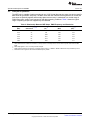
PWM frequencies, system clock frequencies and other operating conditions. Table 3 shows the typical
range of operating frequencies supported by the HRPWM.
Table 3. Relationship Between MEP Steps, PWM Frequency and Resolution
System
(MHz)
(1)
(2)
(3)
(4)
(5)
12
MEP Steps Per
SYSCLKOUT (1) (2)
(3)
PWM MIN
(Hz) (4)
PWM MAX
(MHz)
Res. @ MAX
(Bits) (5)
50.0
111
763
2.50
11.1
60.0
93
916
3.00
10.9
70.0
79
1068
3.50
10.6
80.0
69
1221
4.00
10.4
90.0
62
1373
4.50
10.3
100.0
56
1526
5.00
10.1
System frequency = SYSCLKOUT, i.e., CPU clock. TBCLK =SYSCLKOUT.
Table data based on a MEP time resolution of 180 ps (this is an example value, see the device-specific data sheet for MEP
limits.
MEP steps applied = TSYSCLKOUT/180 ps in this example.
PWM minimum frequency is based on a maximum period value, i.e., TBPRD = 65535. PWM mode is asymmetrical up-count.
Resolution in bits is given for the maximum PWM frequency stated.
High-Resolution Pulse Width Modulator (HRPWM)
SPRU924F – April 2005 – Revised October 2011
Submit Documentation Feedback
Copyright © 2005–2011, Texas Instruments Incorporated
Operational Description of HRPWM
www.ti.com
2.3.1
Edge Positioning
In a typical power control loop (e.g., switch modes, digital motor control [DMC], uninterruptible power
supply [UPS]), a digital controller (PID, 2pole/2zero, lag/lead, etc.) issues a duty command, usually
expressed in a per unit or percentage terms. Assume that for a particular operating point, the demanded
duty cycle is 0.405 or 40.5% on time and the required converter PWM frequency is 1.25 MHz. In
conventional PWM generation with a system clock of 100 MHz, the duty cycle choices are in the vicinity of
40.5%. In Figure 5, a compare value of 32 counts (i.e., duty = 40% ) is the closest to 40.5% that you can
attain. This is equivalent to an edge position of 320 ns instead of the desired 324 ns. This data is shown in
Table 4.
By utilizing the MEP, you can achieve an edge position much closer to the desired point of 324 ns.
Table 4 shows that in addition to the CMPA value, 22 steps of the MEP (CMPAHR register) will position
the edge at 323.96 ns, resulting in almost zero error. In this example, it is assumed that the MEP has a
step resolution of 180 ps.
Figure 5. Required PWM Waveform for a Requested Duty = 40.5%
Tpwm = 800 ns
324 ns
Demanded
duty (40.5%)
10 ns steps
30 31 32 33 34
0
79
EPWM1A
37.5%
40.0%
38.8%
SPRU924F – April 2005 – Revised October 2011
Submit Documentation Feedback
42.5%
41.3%
High-Resolution Pulse Width Modulator (HRPWM)
Copyright © 2005–2011, Texas Instruments Incorporated
13
Operational Description of HRPWM
www.ti.com
Table 4. CMPA vs Duty (left), and [CMPA:CMPAHR] vs Duty (right)
CMPA (count) (1)
(2) (3)
DUTY
%
High
Time
(ns)
CMPA
(count)
CMPAHR
(count)
Duty
(%)
High
Time
(ns)
28
35.0
280
32
18
40.405
323.24
29
36.3
290
32
19
40.428
323.42
30
37.5
300
32
20
40.450
323.60
31
38.8
310
32
21
40.473
323.78
32
40.0
320
32
22
40.495
323.96
33
41.3
330
32
23
40.518
324.14
34
42.5
340
32
24
40.540
324.32
32
25
40.563
324.50
32
26
40.585
324.68
32
27
40.608
324.86
Required
32.40
(1)
(2)
(3)
2.3.2
40.5
324
System clock, SYSCLKOUT and TBCLK = 100 MHz, 10 ns
For a PWM Period register value of 80 counts, PWM Period = 80 x 10 ns = 800 ns, PWM frequency = 1/800 ns = 1.25 MHz
Assumed MEP step size for the above example = 180 ps
See the device-specific data manual for typical and maximum MEP values.
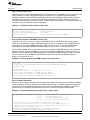
Scaling Considerations
The mechanics of how to position an edge precisely in time has been demonstrated using the resources
of the standard CMPA and MEP (CMPAHR) registers. In a practical application, however, it is necessary
to seamlessly provide the CPU a mapping function from a per-unit (fractional) duty cycle to a final integer
(non-fractional) representation that is written to the [CMPA:CMPAHR] register combination.
To do this, first examine the scaling or mapping steps involved. It is common in control software to
express duty cycle in a per-unit or percentage basis. This has the advantage of performing all needed
math calculations without concern for the final absolute duty cycle, expressed in clock counts or high time
in ns. Furthermore, it makes the code more transportable across multiple converter types running different
PWM frequencies.
To implement the mapping scheme, a two-step scaling procedure is required.
14
High-Resolution Pulse Width Modulator (HRPWM)
SPRU924F – April 2005 – Revised October 2011
Submit Documentation Feedback
Copyright © 2005–2011, Texas Instruments Incorporated
Operational Description of HRPWM
www.ti.com
Assumptions for this example:
System clock , SYSCLKOUT
PWM frequency
Required PWM duty cycle, PWMDuty
PWM period in terms of coarse steps,
PWMperiod (800 ns/10 ns)
Number of MEP steps per coarse step at
180 ps (10 ns /180 ps ), MEP_ScaleFactor
Value to keep CMPAHR within the range of
1-255 and fractional rounding constant
(default value)
=
=
=
=
10 ns (100 MHz)
1.25 MHz (1/800 ns)
0.405 (40.5%)
80
= 55
= 1.5 (0180h in Q8 format)
Step 1: Percentage Integer Duty value conversion for CMPA register
CMPA register value
=
=
=
=
CMPA register value
int(PWMDuty*PWMperiod); int means integer part
int(0.405*80 )
int(32.4 )
32 (20h)
Step 2: Fractional value conversion for CMPAHR register
CMPAHR register value
= (frac(PWMDuty*PWMperiod)*MEP_ScaleFactor
+1.5) << 8); frac means fractional part
= (frac(32.4) *55 + 1.5) <<8 Shift is to move the value as
CMPAHR high byte
= (0.4 * 55 + 1.5) <<8
= (22 + 1.5) <<8
= 23.5 * 256; Shifting left by 8 is the same as multiplying
by 256.
= 6016
= 1780h CMPAHR value = 1700h , lower 8 bits will be
ignored by hardware.
CMPAHR value
SPRU924F – April 2005 – Revised October 2011
Submit Documentation Feedback
High-Resolution Pulse Width Modulator (HRPWM)
Copyright © 2005–2011, Texas Instruments Incorporated
15
Operational Description of HRPWM
www.ti.com
NOTE: The MEP scale factor (MEP_ScaleFactor) varies with the system clock and DSP operating
conditions. TI provides an MEP scale factor optimizing (SFO) software C function, which
uses the built in diagnostics in each HRPWM and returns the best scale factor for a given
operating point.
The scale factor varies slowly over a limited range so the optimizing C function can be run
very slowly in a background loop.
The CMPA and CMPAHR registers are configured in memory so that the 32-bit data
capability of the 28x CPU can write this as a single concatenated value, i.e.,
[CMPA:CMPAHR].
The mapping scheme has been implemented in both C and assembly, as shown in
Section 2.5. The actual implementation takes advantage of the 32-bit CPU architecture of the
28xx, and is somewhat different from the steps shown in Section 2.3.2.
For time critical control loops where every cycle counts, the assembly version is
recommended. This is a cycle optimized function (11 SYSCLKOUT cycles ) that takes a Q15
duty value as input and writes a single [CMPA:CMPAHR] value.
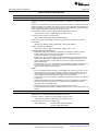
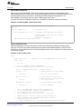
2.3.3
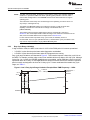
Duty Cycle Range Limitation
In high resolution mode, the MEP is not active for 100% of the PWM period. It becomes operational:
• 3 SYSCLK cycles after the period starts when diagnostics are disabled
• 6 SYSCLK cycles after the period starts when SFO diagnostics are running
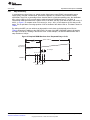
Duty cycle range limitations are illustrated in Figure 6 . This limitation imposes a lower duty cycle limit on
the MEP. For example, precision edge control is not available all the way down to 0% duty cycle. Although
for the first 3 or 6 cycles, the HRPWM capabilities are not available, regular PWM duty control is still fully
operational down to 0% duty. In most applications this should not be an issue as the controller regulation
point is usually not designed to be close to 0% duty cycle. To better understand the useable duty cycle
range, see Table 5 .
Figure 6. Low % Duty Cycle Range Limitation Example When PWM Frequency = 1 MHz
TPWM = 1000 ns
(FPWM = 1 MHz)
60 ns
30 ns
0
3
SYSCLKOUT =
TBCLK =
100 MHz
6
100
EPWM1A
16
High-Resolution Pulse Width Modulator (HRPWM)
SPRU924F – April 2005 – Revised October 2011
Submit Documentation Feedback
Copyright © 2005–2011, Texas Instruments Incorporated
Operational Description of HRPWM
www.ti.com
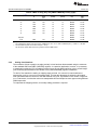
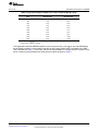
Table 5. Duty Cycle Range Limitation for 3 and 6 SYSCLK/TBCLK Cycles
(1)
PWM Frequency (1)
(kHz)
3 Cycles
Minimum Duty
6 Cycles SYSCLKOUT
Minimum Duty
200
0.6%
1.2%
400
1.2%
2.4%
600
1.8%
3.6%
800
2.4%
4.8%
1000
3.0%
6.0%
1200
3.6%
7.2%
1400
4.2%
8.4%
1600
4.8%
9.6%
1800
5.4%
10.8%
2000
6.0%
12.0%
System clock - TSYSCLKOUT = 10 ns
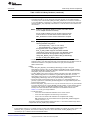
System clock = TBCLK = 100 MHz
If the application demands HRPWM operation in the low percent duty cycle region, then the HRPWM can
be configured to operate in count-down mode with the rising edge position (REP) controlled by the MEP.
This is illustrated in Figure 7. In this case, low percent duty limitation is no longer an issue. However, there
will be a maximum duty limitation with same percent numbers as given in Table 5 .
SPRU924F – April 2005 – Revised October 2011
Submit Documentation Feedback
High-Resolution Pulse Width Modulator (HRPWM)
Copyright © 2005–2011, Texas Instruments Incorporated
17
Operational Description of HRPWM
www.ti.com
Figure 7. High % Duty Cycle Range Limitation Example when PWM Frequency = 1 MHz
Tpwm = 1000 ns
(Fpwm = 1 MHz)
60 ns
30 ns
SYSCLKOUT = 100 MHz
0
3
100
6
EPWM1A
2.4
Scale Factor Optimizing Software (SFO)
The micro edge positioner (MEP) logic is capable of placing an edge in one of 255 discrete time steps. As
previously mentioned, the size of these steps is on the order of 150 ps (see device-specific data sheet for
typical MEP step size on your device). The MEP step size varies based on worst-case process
parameters, operating temperature, and voltage. MEP step size increases with decreasing voltage and
increasing temperature and decreases with increasing voltage and decreasing temperature. Applications
that use the HRPWM feature should use the TI-supplied MEP scale factor optimizer (SFO) software
function. The SFO function helps to dynamically determine the number of MEP steps per SYSCLKOUT
period while the HRPWM is in operation.
To utilize the MEP capabilities effectively during the Q15 duty to [CMPA:CMPAHR] mapping function (see
Section 2.3.2), the correct value for the MEP scaling factor (MEP_ScaleFactor) needs to be known by the
software. To accomplish this, each HRPWM module has built in self-check and diagnostics capabilities
that can be used to determine the optimum MEP_ScaleFactor value for any operating condition. TI
provides a C-callable library containing two SFO functions that utilize this hardware and determines the
optimum MEP_ScaleFactor. As such, MEP Control and Diagnostics registers are reserved for TI use.
Currently, there are two released versions of the SFO library - SFO_TI_Build.lib and SFO_TI_Build_V5.lib.
Versions 2, 3, and 4 were TI Internal only. A detailed description of the SFO_TI_Build.lib software
functions follows below.
NOTE: Information on the SFO_TI_Build_V5.lib software functions, which support up to 16 HRPWM
channels, can be found in Appendix A, along with a high-level comparison table between the two library
versions.
Table 6 provides functional descriptions of the two SFO library routines in SFO_TI_Build.lib.
Table 6. SFO Library Routines
Function
Description
SFO_MepDis(n) Scale Factor Optimizer with MEP Disabled
This routine runs faster, as the calibration logic works when HRPWM capabilities are disabled; therefore,
HRPWM capabilities cannot be run concurrently when the ePWMn is being used.
If SYSCLKOUT = TBCLK = 100 MHz and assuming MEP steps size is 150 ps
Typical value at 100 MHz = 66 MEP steps per unit TBCLK (10 ns)
The function returns a value in the variable array:
MEP_ScaleFactor[n] = Number of MEP steps/SYSCLKOUT
If TBCLK is not equal to SYSCLKOUT, then the returned value must be adjusted to reflect the correct TBCLK:
MEP steps per TBCLK = MEP_ScaleFactor[n] * (SYSCLKOUT/TBCLK) (1)
Example: If TBCLK =SYSCLKOUT/2,
(1)
18
n is the ePWM module number on which the SFO function operates.
e.g., n = 1, 2, 3, or 4 for the F2808. Check your device data manual for device configurations.
High-Resolution Pulse Width Modulator (HRPWM)
SPRU924F – April 2005 – Revised October 2011
Submit Documentation Feedback
Copyright © 2005–2011, Texas Instruments Incorporated
Operational Description of HRPWM
www.ti.com
Table 6. SFO Library Routines (continued)
Function
Description
MEP steps per TBCLK = MEP_ScaleFactor[n] * (100/50) =66 * 2 = 132
(1)
Constraints when using this function:
SFO_MepDis(n) can be used with SYSCLKOUT from 50 MHz to maximum SYSCLK frequency. MEP
diagnostics logic uses SYSCLKOUT not TBCLK and hence SYSCLKOUT restriction is an important constraint.
SFO_MepDis(n) function does not require a starting Scale Factor value. Additionally, TBCLK must equal
SYSCLKOUT.
When to use
If one of the ePWM modules is not used in HRPWM mode, then it can be dedicated to run the SFO diagnostics
for the modules that are running HRPWM mode. Here the single MEP_ScaleFactor value obtained can be
applied to other ePWM modules. This assumes that all HRPWM module’s MEP steps are similar but may not be
identical.
The ePWM module that is not active in HRPWM mode is still fully operational in conventional PWM mode and
can be used to drive PWM pins. The SFO function only makes use of the MEP diagnostics logic.
The other ePWM modules operating in HRPWM mode incur only a 3-cycle minimum duty limitation.
SFO_MepEn(n)
Scale Factor Optimizer with MEP Enabled
This routine runs slower as the calibration logic is used concurrently while HRPWM capabilities are being used
by the ePWM module.
If SYSCLKOUT = TBCLK = 100 MHz and assuming MEP steps size is 150 ps
Typical value at 100 MHz = 66 MEP steps per unit TBCLK (10 ns)
The function returns a value in the variable array:
MEP_ScaleFactor[n] (2)
= Number of MEP steps/SYSCLKOUT
= Number of MEP steps/TBCLK
Constraints when using this function:
SFO_MepEn(n) function is restricted to be used with SYSCLKOUT of 60 MHz maximum SYSCLK frequency.
MEP diagnostics logic uses SYSCLKOUT not TBCLK and hence SYSCLKOUT restriction is an important
constraint. SFO_MepEn(n) function does require a starting Scale Factor value.MEP_ScaleFactor[0] needs to be
initialized to a typical MEP step size value. Additionally, TBCLK must equal SYSCLKOUT.
NOTE:
SFO_MepEn(n) only supports the following HRPWM configuration:
• HRCNFG[HRLOAD] = 0 (load on CTR = ZERO)
• HRCNFG[EDGMODE] = 10 (falling edge MEP control)
SFO_MepEn(n)_V5B.lib includes an SFO_MepEn(n)_V5(n) function which
does not have this limitation.
When to use
If the application requires all ePWM modules to have HRPWM capability (i.e., MEP is operational), then the
SFO_MepEn(n) function can run for each of the active ePWM modules with HRPWM capability.
• In the above case, a 6-cycle MEP inactivity zone exists at the start of the PWM period. See Section 2.3.3
on duty cycle range limitation.
• It is also possible to run the SFO_MepEn(n) function for only one ePWM module and to use the SFO return
value for the other modules. In this case only one ePWM module incurs the 6-cycle limitation, and
remaining modules incur only a 3-cycle minimum duty limitation. See “Duty cycle limitation” section. This
assumes that all HRPWM module’s MEP steps are similar but may not be identical.
(2)
n is the ePWM module number on which the SFO function operates.
e.g., n = 1, 2, 3, or 4 for the F2808. Check your device data manual for device configurations.
Both routines can be run as background tasks in a slow loop requiring negligible CPU cycles. In most
applications only one of these routines will be needed. However, if the application has free HRPWM
resources then both the routines could be used. The repetition rate at which an SFO function needs to be
executed depends on the applications operating environment. As with all digital CMOS devices
temperature and supply voltage variations have an effect on MEP operation. However, in most
applications these parameters vary slowly and therefore it is often sufficient to execute the SFO function
once every 5 to 10 seconds or so. If more rapid variations are expected, then execution may have to be
performed more frequently to match the application. Note, there is no high limit restriction on the SFO
function repetition rate, hence it can execute as quickly as the background loop is capable.
SPRU924F – April 2005 – Revised October 2011
Submit Documentation Feedback
High-Resolution Pulse Width Modulator (HRPWM)
Copyright © 2005–2011, Texas Instruments Incorporated
19
Operational Description of HRPWM
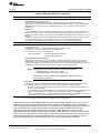
www.ti.com
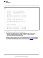
While using HRPWM feature with no SFO diagnostics, HRPWM logic will not be active for the first 3
TBCLK cycles of the PWM period. While running the application in this configuration, if CMPA register
value is less than 3 cycles, then its CMPAHR register must be cleared to zero. This would avoid any
unexpected transitions on PWM signal.
However, if SFO diagnostic function SFO_MepEn is used in the background, then HRPWM logic will not
be active for the first 6 TBCLK cycles of PWM period. While using SFO_MepEn function if CMPA register
value is less than 6 cycles, then its CMPAHR register must be cleared to zero. This would avoid any
unexpected transitions on PWM signal. Also note that the SFO_MepDis function cannot be used
concurrently with PWM signals with HRPWM enabled (see the previous section for details).
2.4.1
Software Usage
Software library functions SFO_MepEn(int n) and SFO_MepDis(int n) calculate the MEP scale factor for
ePWMn modules, where n = 1, 2, 3, or 4. The scale factor is an integer value in the range 1 – 255, and
represents the number of micro step edge positions available for a system clock period. The scale factor
value is returned in an array of integer variables of length 5 called MEP_ScaleFactor[5]. For example, see
Table 7.
20
High-Resolution Pulse Width Modulator (HRPWM)
SPRU924F – April 2005 – Revised October 2011
Submit Documentation Feedback
Copyright © 2005–2011, Texas Instruments Incorporated
Operational Description of HRPWM
www.ti.com
Table 7. Factor Values
Software function calls
Functional description
Updated Variable
MEP_ScaleFactor[5]
(1)
SFO_MepDis(n)
SFO_MepDis(1);
Returns the scale factor value to array index 1
MEP_ScaleFactor[1]
SFO_MepDis(2);
Returns the scale factor value to array index 2
MEP_ScaleFactor[2]
SFO_MepDis(3);
Returns the scale factor value to array index 3
MEP_ScaleFactor[3]
SFO_MepDis(4);
Returns the scale factor value to array index 4
MEP_ScaleFactor[4]
SFO_MepEn(1);
Returns the scale factor value to array index 1
MEP_ScaleFactor[1]
SFO_MepEn(2);
Returns the scale factor value to array index 2
MEP_ScaleFactor[2]
SFO_MepEn(3);
Returns the scale factor value to array index 3
MEP_ScaleFactor[3]
SFO_MepEn(4);
Returns the scale factor value to array index 4
MEP_ScaleFactor[4]
SFO_MepEn(n)
(1)
MEP_ScaleFactor[0] variable is a starting value and used by the SFO software functions internally
To use the HRPWM feature of the ePWMs it is recommended that the SFO functions be used as
described here.
Step 1. Add Include Files
The SFO.h file needs to be included as follows. This include file is mandatory while using the SFO library
function. For theTMS320F280x devices, the C280x C/C++ Header Files and Peripheral Examples
(literature number SPRC191). DSP280x_Device.h and DSP280x_PWM_defines.h are necessary as they
are used with all TI software examples. These include files are optional if customized header files are
used in the end applications.
Example 1. A Sample of How to Add Include Files
#include "DSP280x_Device.h" // DSP280x Headerfile
#include "DSP280x_EPWM_defines.h" // init defines
#include "SFO.h" // SFO lib functions (needed for HRPWM)
Step 2. Element Declaration
Declare a 5-element array of integer variables as follows:
Example 2. Declaring an Element
int MEP_ScaleFactor[5] = {0,0,0,0,0}; // Scale factor values for ePWM1-4
int MEP_ScaleFactor1, MEP_ScaleFactor2, MEP_ScaleFactor3, MEP_ScaleFactor4 // Not required by library
volatile struct EPWM_REGS *ePWM[] = {0, &EPwm1Regs, &EPwm2Regs, &EPwm3Regs, &EPwm4Regs};
Step 3. MEP_ScaleFactor Initialization
After power up, the SFO_MepEn(n) function needs a starting Scale Factor value. This value can be
conveniently determined by using one of the ePWM modules to run the SFO_MepDis(n) function prior to
configuring its PWM outputs for the application. SFO_MepDis(n) function does not require a starting Scale
Factor value.
As part of the one-time initialization code, include the following:
Example 3. Initializing With a Scale Factor Value
// MEP_ScaleFactor variables initialized using function SFO_MepDis
while (MEP_ScaleFactor[1] == 0) SFO_MepDis(1); //SFO for HRPWM1
while (MEP_ScaleFactor[2] == 0) SFO_MepDis(2); //SFO for HRPWM2
SPRU924F – April 2005 – Revised October 2011
Submit Documentation Feedback
High-Resolution Pulse Width Modulator (HRPWM)
Copyright © 2005–2011, Texas Instruments Incorporated
21
Operational Description of HRPWM
www.ti.com
Example 3. Initializing With a Scale Factor Value (continued)
while (MEP_ScaleFactor[3] == 0) SFO_MepDis(3); //SFO for HRPWM3
while (MEP_ScaleFactor[4] == 0) SFO_MepDis(4); //SFO for HRPWM4
// Initialize a common seed variable MEP_ScaleFactor[0] // required for all SFO functions
MEP_ScaleFactor[0] = MEP_ScaleFactor[1];
// Common variable for SFOMepEn(n) function
Step 4. Application Code
While the application is running, fluctuations in both device temperature and supply voltage may be
expected. To be sure that optimal Scale Factors are used for each ePWM module, the SFO function
should be re-run periodically as part of a slower back-ground loop. Some examples of this are shown
here.
NOTE: See the HRPWM_SFO example in the C280x C/C++ Header Files and Peripheral Examples
(SPRC191) available from the TI website.
22
High-Resolution Pulse Width Modulator (HRPWM)
SPRU924F – April 2005 – Revised October 2011
Submit Documentation Feedback
Copyright © 2005–2011, Texas Instruments Incorporated
Operational Description of HRPWM
www.ti.com
Example 4. SFO Function Calls
main()
{
//
//
User code
Case1: ePWM1,2,3,4 are running in HRPWM mode
SFO_MepEn(1); // Each of these of function enables
SFO_MepEn(2); // the respective MEP diagnostic logic
SFO_MepEn(3); // and returns MEP Scale factor value
SFO_MepEn(4);
MEP_ScaleFactor1
MEP_ScaleFactor2
MEP_ScaleFactor3
MEP_ScaleFactor4
//
//
//
//
//
//
=
=
=
=
MEP_ScaleFactor[1];
MEP_ScaleFactor[2];
MEP_ScaleFactor[3];
MEP_ScaleFactor[4];
//
//
//
//
for
for
for
for
ePWM1
ePWM2
ePWM3
ePWM4
Case2:ePWM1,2,3 only are running in HRPWM mode.
One of the ePWM channel(as an example ePWM4) is used as for
Scale factor calibration
Here minimum duty cycle limitation is 3 clock cycles.
HRPWM 4 MEP diagnostics circuit is used to estimate the MEP steps
with the assumption that all HRPWM channels behave similarly
though may not be identical.
SFO_MepDis(4); // MEP steps using ePWM4
MEP_ScaleFactor1 = MEP_ScaleFactor[4]; //
MEP_ScaleFactor2 = MEP_ScaleFactor1
//
MEP_ScaleFactor3 = MEP_ScaleFactor1
//
MEP_ScaleFactor4 = MEP_ScaleFactor1
//
2.5
used
used
used
used
used
used
used
used
for
for
for
for
ePWM1
ePWM2
ePWM3
ePWM4
HRPWM Examples Using Optimized Assembly Code
The best way to understand how to use the HRPWM capabilities is through two real examples:
1. Simple buck converter using asymmetrical PWM (i.e. count-up) with active high polarity.
2. DAC function using simple R+C reconstruction filter.
The following examples all have Initialization/configuration code written in C. To make these easier to
understand, the #defines shown below are used. Note, #defines introduced in TMS320x280x Enhanced
Pulse Width Modulator (ePWM) Module Reference Guide (literature number SPRU791) are also used.
Example 5 This example assumes MEP step size of 150 ps and does not use the SFO library.
SPRU924F – April 2005 – Revised October 2011
Submit Documentation Feedback
High-Resolution Pulse Width Modulator (HRPWM)
Copyright © 2005–2011, Texas Instruments Incorporated
23
Operational Description of HRPWM
www.ti.com
Example 5. #Defines for HRPWM Header Files
//-------------------------------// HRPWM (High Resolution PWM)
//================================
// HRCNFG
#define HR_Disable 0x0
#define HR_REP 0x1
// Rising Edge position
#define HR_FEP 0x2
// Falling Edge position
#define HR_BEP 0x3
// Both Edge position
#define HR_CMP 0x0
// CMPAHR controlled
#define HR_PHS 0x1
// TBPHSHR controlled
#define HR_CTR_ZERO 0x0
// CTR = Zero event
#define HR_CTR_PRD 0x1
// CTR = Period event
2.5.1
Implementing a Simple Buck Converter
In
•
•
•
this example, the PWM requirements are:
PWM frequency = 1 MHz (i.e., TBPRD = 100 )
PWM mode = asymmetrical, up-count
Resolution = 12.7 bits (with a MEP step size of 150 ps)
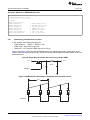
Figure 8 and Figure 9 show the required PWM waveform. As explained previously, configuration for the
ePWM1 module is almost identical to the normal case except that the appropriate MEP options need to be
enabled/selected.
Figure 8. Simple Buck Controlled Converter Using a Single PWM
Vin1
Vout1
Buck
EPWM1A
Figure 9. PWM Waveform Generated for Simple Buck Controlled Converter
Tpwrr
Z
CA
Z
CA
Z
EPWM1A
24
High-Resolution Pulse Width Modulator (HRPWM)
SPRU924F – April 2005 – Revised October 2011
Submit Documentation Feedback
Copyright © 2005–2011, Texas Instruments Incorporated
Operational Description of HRPWM
www.ti.com
The example code shown consists of two main parts:
• Initialization code (executed once)
• Run time code (typically executed within an ISR)
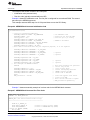
Example 6 shows the Initialization code. The first part is configured for conventional PWM. The second
part sets up the HRPWM resources.
This example assumes MEP step size of 150 ps and does not use the SFO library.
Example 6. HRPWM Buck Converter Initialization Code
void HrBuckDrvCnf(void)
{
// Config for conventional PWM first
EPwm1Regs.TBCTL.bit.PRDLD = TB_IMMEDIATE;
// set Immediate load
EPwm1Regs.TBPRD = 100;
// Period set for 1000 kHz PWM
hrbuck_period = 200;
// Used for Q15 to Q0 scaling
EPwm1Regs.TBCTL.bit.CTRMODE = TB_COUNT_UP;
EPwm1Regs.TBCTL.bit.PHSEN = TB_DISABLE;
// EPWM1 is the Master
EPwm1Regs.TBCTL.bit.SYNCOSEL = TB_SYNC_DISABLE;
EPwm1Regs.TBCTL.bit.HSPCLKDIV = TB_DIV1;
EPwm1Regs.TBCTL.bit.CLKDIV = TB_DIV1;
// Note: ChB is initialized here only for comparison purposes, it is not required
EPwm1Regs.CMPCTL.bit.LOADAMODE
EPwm1Regs.CMPCTL.bit.SHDWAMODE
EPwm1Regs.CMPCTL.bit.LOADBMODE
EPwm1Regs.CMPCTL.bit.SHDWBMODE
//
=
=
=
=
CC_CTR_ZERO;
CC_SHADOW;
CC_CTR_ZERO;
CC_SHADOW;
EPwm1Regs.AQCTLA.bit.ZRO = AQ_SET;
EPwm1Regs.AQCTLA.bit.CAU = AQ_CLEAR;
EPwm1Regs.AQCTLB.bit.ZRO = AQ_SET;
EPwm1Regs.AQCTLB.bit.CBU = AQ_CLEAR;
Now configure the HRPWM resources
EALLOW;
EPwm1Regs.HRCNFG.all = 0x0;
EPwm1Regs.HRCNFG.bit.EDGMODE = HR_FEP;
EPwm1Regs.HRCNFG.bit.CTLMODE = HR_CMP;
EPwm1Regs.HRCNFG.bit.HRLOAD = HR_CTR_ZERO;
EDIS;
MEP_ScaleFactor = 66*256;
// optional
// optional
//
//
optional
optional
//
//
//
//
//
//
Note these registers are protected
and act only on ChA
clear all bits first
Control Falling Edge Position
CMPAHR controls the MEP
Shadow load on CTR=Zero
//
//
//
//
Start with typical Scale Factor
value for 100 MHz
Note: Use SFO functions to update
MEP_ScaleFactor dynamically
}
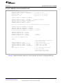
Example 7 shows an assembly example of run-time code for the HRPWM buck converter.
Example 7. HRPWM Buck Converter Run-Time Code
EPWM1_BASE .set 0x6800
CMPAHR1 .set EPWM1_BASE+0x8
;===============================================
HRBUCK_DRV; (can execute within an ISR or loop)
;===============================================
MOVW DP, #_HRBUCK_In
MOVL XAR2,@_HRBUCK_In
MOVL XAR3,#CMPAHR1
; Output for EPWM1A (HRPWM)
MOV T,*XAR2
; Pointer to Input Q15 Duty (XAR2)
; Pointer to HRPWM CMPA reg (XAR3)
; T <= Duty
SPRU924F – April 2005 – Revised October 2011
Submit Documentation Feedback
High-Resolution Pulse Width Modulator (HRPWM)
Copyright © 2005–2011, Texas Instruments Incorporated
25
Operational Description of HRPWM
www.ti.com
Example 7. HRPWM Buck Converter Run-Time Code (continued)
MPYU ACC,T,@_hrbuck_period
; Q15 to Q0 scaling based on Period
MOV T,@_MEP_ScaleFactor
; MEP scale factor (from optimizer s/w)
MPYU P,T,@AL
; P <= T * AL, Optimizer scaling
MOVH @AL,P
; AL <= P, move result back to ACC
ADD ACC, #0x180
; MEP range and rounding adjustment
MOVL *XAR3,ACC
; CMPA:CMPAHR(31:8) <= ACC
; Output for EPWM1B (Regular Res) Optional - for comparison purpose only
MOV *+XAR3[2],AH ; Store ACCH to regular CMPB
2.5.2
Implementing a DAC function Using an R+C Reconstruction Filter
In
•
•
•
this example, the PWM requirements are:
PWM frequency = 400 kHz (i.e., TBPRD = 250)
PWM mode = Asymmetrical, Up-count
Resolution = 14 bits ( MEP step size = 150 ps)
Figure 10 and Figure 11 show the DAC function and the required PWM waveform. As explained
previously, configuration for the ePWM1 module is almost identical to the normal case except that the
appropriate MEP options need to be enabled/selected.
Figure 10. Simple Reconstruction Filter for a PWM Based DAC
EPWM1A
VOUT1
LPF
Figure 11. PWM Waveform Generated for the PWM DAC Function
TPWM = 2.5 µs
CA
Z
Z
CA
Z
EPWM1A
The example code shown consists of two main parts:
• Initialization code (executed once)
• Run time code (typically executed within an ISR)
This example assumes a typical MEP_ScaleFactor and does not use the SFO library.
Example 8 shows the Initialization code. The first part is configured for conventional PWM. The second
part sets up the HRPWM resources.
26
High-Resolution Pulse Width Modulator (HRPWM)
SPRU924F – April 2005 – Revised October 2011
Submit Documentation Feedback
Copyright © 2005–2011, Texas Instruments Incorporated
Operational Description of HRPWM
www.ti.com
Example 8. PWM DAC Function Initialization Code
void HrPwmDacDrvCnf(void) {
// Config for conventional PWM first
EPwm1Regs.TBCTL.bit.PRDLD = TB_IMMEDIATE;
EPwm1Regs.TBPRD = 250;
hrDAC_period = 250;
// Set Immediate load
// Period set for 400 kHz PWM
// Used for Q15 to Q0 scaling
EPwm1Regs.TBCTL.bit.CTRMODE = TB_COUNT_UP;
EPwm1Regs.TBCTL.bit.PHSEN = TB_DISABLE;
// EPWM1 is the Master
EPwm1Regs.TBCTL.bit.SYNCOSEL = TB_SYNC_DISABLE;
EPwm1Regs.TBCTL.bit.HSPCLKDIV = TB_DIV1;
EPwm1Regs.TBCTL.bit.CLKDIV = TB_DIV1;
// Note: ChB is initialized here only for comparison purposes, it is not required
EPwm1Regs.CMPCTL.bit.LOADAMODE
EPwm1Regs.CMPCTL.bit.SHDWAMODE
EPwm1Regs.CMPCTL.bit.LOADBMODE
EPwm1Regs.CMPCTL.bit.SHDWBMODE
EPwm1Regs.AQCTLA.bit.ZRO
EPwm1Regs.AQCTLA.bit.CAU
EPwm1Regs.AQCTLB.bit.ZRO
EPwm1Regs.AQCTLB.bit.CBU
=
=
=
=
=
=
=
=
CC_CTR_ZERO;
CC_SHADOW;
CC_CTR_ZERO; // optional
CC_SHADOW;
// optional
AQ_SET;
AQ_CLEAR;
AQ_SET;
AQ_CLEAR;
// optional
// optional
// Now configure the HRPWM resources
EALLOW;
EPwm1Regs.HRCNFG.all = 0x0;
EPwm1Regs.HRCNFG.bit.EDGMODE = HR_FEP;
EPwm1Regs.HRCNFG.bit.CTLMODE = HR_CMP;
EPwm1Regs.HRCNFG.bit.HRLOAD = HR_CTR_ZERO;
EDIS;
MEP_ScaleFactor = 66*256;
//
//
//
//
//
//
Note these registers are protected
and act only on ChA.
Clear all bits first
Control falling edge position
CMPAHR controls the MEP.
Shadow load on CTR=Zero.
//
//
//
//
Start with typical Scale Factor
value for 100 MHz.
Use SFO functions to update
MEP_ScaleFactor dynamically
}
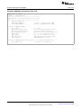
Example 9 shows an assembly example of run-time code that can execute in a high-speed ISR loop.
SPRU924F – April 2005 – Revised October 2011
Submit Documentation Feedback
High-Resolution Pulse Width Modulator (HRPWM)
Copyright © 2005–2011, Texas Instruments Incorporated
27
Operational Description of HRPWM
www.ti.com
Example 9. PWM DAC Function Run-Time Code
EPWM1_BASE .set 0x6800
CMPAHR1 .set EPWM1_BASE+0x8
;=================================================
HRPWM_DAC_DRV; (can execute within an ISR or loop)
;=================================================
MOVW DP, #_HRDAC_In
MOVL XAR2,@_HRDAC_In
; Pointer to input Q15 duty (XAR2)
MOVL XAR3,#CMPAHR1
; Pointer to HRPWM CMPA reg (XAR3)
; Output for EPWM1A (HRPWM)
MOV T,*XAR2
MPY ACC,T,@_hrDAC_period
ADD ACC,@_HrDAC_period<<15
MOV T,@_MEP_ScaleFactor
MPYU P,T,@AL
MOVH @AL,P
ADD ACC, #0x180
MOVL *XAR3,ACC
;
;
;
;
;
;
;
;
T <= duty
Q15 to Q0 scaling based on period
Offset for bipolar operation
MEP scale factor (from optimizer s/w)
P <= T * AL, optimizer scaling
AL <= P, move result back to ACC
MEP range and rounding adjustment
CMPA:CMPAHR(31:8) <= ACC
; Output for EPWM1B (Regular Res) Optional - for comparison purpose only
MOV *+XAR3[2],AH
; Store ACCH to regular CMPB
28
High-Resolution Pulse Width Modulator (HRPWM)
SPRU924F – April 2005 – Revised October 2011
Submit Documentation Feedback
Copyright © 2005–2011, Texas Instruments Incorporated
HRPWM Register Descriptions
www.ti.com
3
HRPWM Register Descriptions
This section describes the applicable HRPWM registers
3.1
Register Summary
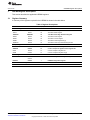
A summary of the registers required for the HRPWM is shown in the table below.
Table 8. Register Descriptions
Name
Offset
Size (x16)
Description
TBCTL
0x0000
1/0
Time Base Control Register
TBSTS
0x0001
1/0
Time Base Status Register
Time Base Registers
TBPHSHR
TBPHSHR
1/0
Time Base Phase High Resolution Register
TBPHS
0x0003
1/0
Time Base Phase Register
TBCNT
0x0004
1/0
Time Base Counter Register
TBPRD
0x0005
1/1
Time Base Period Register Set [3]
TBPRDHR
0x0006
1/0
Time Base Period High Resolution Register Set
CMPCTL
0x0007
1/0
Counter Compare Control Register
CMPAHR
0x0008
1/1
Counter Compare A High Resolution Register Set
CMPA
0x0009
1/1
Counter Compare A Register Set
CMPB
0x000A
1/1
Counter Compare B Register Set [4]
0x0000 to
0x001F
32
Other ePWM registers including the ones given above.
0x0020
1
HRPWM Configuration Register
Compare Registers
EPWM Registers
ePWM
HRCNFG
EPWM/HRPWM Test Registers
Reserved
0x0030 0x003F
SPRU924F – April 2005 – Revised October 2011
Submit Documentation Feedback
16
High-Resolution Pulse Width Modulator (HRPWM)
Copyright © 2005–2011, Texas Instruments Incorporated
29
HRPWM Register Descriptions
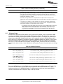
3.2
www.ti.com
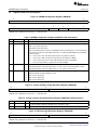
Registers and Field Descriptions
Figure 12. HRPWM Configuration Register (HRCNFG)
15
8
Reserved
R-0
7
3
2
Reserved
4
HRLOAD
CTLMODE
1
EDGMODE
0
R-0
R/W-0
R/W-0
R/W-0
LEGEND: R/W = Read/Write; R = Read only; -n = value after reset
Table 9. HRPWM Configuration Register (HRCNFG) Field Descriptions
Bit
Field
Value Description
(1)
15-4
Reserved
Reserved
3
HRLOAD
Shadow mode bit: Selects the time event that loads the CMPAHR shadow value into the active register:
0
CTR = zero (counter equal zero)
1
CTR=PRD (counter equal period)
Note: Load mode selection is valid only if CTLMODE=0 has been selected (bit 2). You should select this
event to match the selection of the CMPA load mode ( i.e., CMPCTL[LOADMODE] bits) in the EPWM
module as follows:
2
1-0
(1)
CTLMODE
00
Load on CTR = Zero: Time-base counter equal to zero (TBCTR = 0x0000)
01
Load on CTR = PRD: Time-base counter equal to period (TBCTR = TBPRD)
10
Load on either CTR = Zero or CTR = PRD (should not be used with HRPWM)
11
Freeze (no loads possible – should not be used with HRPWM)
Control Mode Bits: Selects the register (CMP or TBPHS) that controls the MEP:
0
CMPAHR(8) Register controls the edge position ( i.e., this is duty control mode). (default on reset)
1
TBPHSHR(8) Register controls the edge position ( i.e., this is phase control mode).
EDGMODE
Edge Mode Bits: Selects the edge of the PWM that is controlled by the micro-edge position (MEP) logic:
00
HRPWM capability is disabled (default on reset)
01
MEP control of rising edge
10
MEP control of falling edge
11
MEP control of both edges
This register is EALLOW protected.
Figure 13. Counter Compare A High Resolution Register (CMPAHR)
15
8
7
0
CMPAHR
Reserved
R/W-0
R-0
LEGEND: R/W = Read/Write; R = Read only; -n = value after reset
Table 10. Counter Compare A High Resolution Register (CMPAHR) Field Descriptions
Bit
Field
Value Description
15-8
CMPAHR
Compare A High Resolution register bits for MEP step control. A minimum value of 0x0001 is needed
to enable HRPWM capabilities. Valid MEP range of operation 1-255h.
7-0
Reserved
Any writes to these bit(s) must always have a value of 0.
Figure 14. TB Phase High Resolution Register (TBPHSHR)
15
8
7
0
TBPHSH
Reserved
R/W-0
R-0
LEGEND: R/W = Read/Write; R = Read only; -n = value after reset
30
High-Resolution Pulse Width Modulator (HRPWM)
SPRU924F – April 2005 – Revised October 2011
Submit Documentation Feedback
Copyright © 2005–2011, Texas Instruments Incorporated
HRPWM Register Descriptions
www.ti.com
Table 11. TB Phase High Resolution Register (TBPHSHR) Field Descriptions
Bit
Field
Value
Description
15-8
TBPHSH
Time base phase high resolution bits
7-0
Reserved
Any writes to these bit(s) must always have a value of 0.
SPRU924F – April 2005 – Revised October 2011
Submit Documentation Feedback
High-Resolution Pulse Width Modulator (HRPWM)
Copyright © 2005–2011, Texas Instruments Incorporated
31
32
High-Resolution Pulse Width Modulator (HRPWM)
SPRU924F – April 2005 – Revised October 2011
Submit Documentation Feedback
Copyright © 2005–2011, Texas Instruments Incorporated
Appendix A
www.ti.com
Appendix A SFO Library Software - SFO_TI_Build_V5.lib
This appendix includes a detailed description of the software routines in SFO_TI_Build_V5.lib which
supports up to 16 HRPWM channels.
A.1
SFO Library Version Comparison
Table 12 includes a high-level comparison between SFO_TI_Build.lib and SFO_TI_V5.lib. A detailed
description of SFO_TI_Build_V5.lib follows the table, and more information on SFO_TI_Build.lib can be
found in Section 2.4.
Table 12. SFO Library Version Comparison
SYSCLK Freq
ePWM Freq
SFO_TI_Build.lib
SFO_TI_Build_V5.lib
Max. HRPWM
channels supported
-
-
Up to 4
Up to 16
Total static variable
memory size
-
-
220
79(1 ch.) to 192 (16ch.)
MepEn runs on
multiple channels
concurrently?
-
-
yes
no
-
Error-checking?
-
-
no
yes
-
Typical time requires
for MepEn to update
-
3.33 MHz
0.396
0.18
seconds
-
400 kHz
3.26
1.5
seconds
MEP_ScaleFactor on
1 channel if called
repetitvely without
interrupts
-
1 MHz
1.308
0.6
seconds
-
2 MHz
0.66
0.3
seconds
-
20 MHz
0.066
0.03
seconds
100MHz
0.83
0.83
milliseconds
60MHz
1.38
1.38
milliseconds
50MHz
1.66
1.66
milliseconds
Typical time required
for MepDis to update
MEP_ScaleFactor on
1 channel if called
repetitively without
interrupts
Unit
channels
words
In SFO_TI_Build_V5.lib/SFO_TI_Build_V5B.lib, the diagnostic software has been optimized to use less
memory, to minimize the calibration time, and to support up to 16 HRPWM channels. Table 13 provides
functional description of the two SFO library routines in SFO_TI_Build_V5.lib/SFO_TI_Build_V5B.lib.
SPRU924F – April 2005 – Revised October 2011
Submit Documentation Feedback
SFO Library Software - SFO_TI_Build_V5.lib
Copyright © 2005–2011, Texas Instruments Incorporated
33
SFO Library Version Comparison
www.ti.com
Table 13. SFO V5 Library Routines
Function
int SFO_MepDis_V5(n)
Description
Scale Factor Optimizer V5 with MEP Disabled
This routine is very similar to the SFO_MepDis() routine in the original SFO library, but with one
change. It now returns a 1 when MEP-disabled calibration is complete, or a 0 while calibration is still
running.
This function runs faster than the SFO_V5() routine and cannot be used on an ePWM channel while
HRPWM capablities are enabled for that channel. If there is a spare ePWM channel available in the
system. SFO_MepDis_V5() can be run for that channel, and the resulting MEP_ScaleFactor[n] value
can be copied into the MEP_ScaleFactor[n] for all other channels.
If SYSCLKOUT = TBCLK =100 MHz and assuming the MEP step size is 150 ps:
Typical value at 100 MHz = 66 MEP steps per unit TBCLK (10 ns)
The funtion returns a value in the variable array:
MEP_ScaleFactor[n] Number of MEP steps/SYSCLKOUT
If TBCLK is not equal to SYSCLKOUT, then the returned value must be adjusted to reflect the
correct TBCLK:
MEP steps per TBCLKK =MEP_ScaleFactor[n] * (SYSCLKOUT/TBCLK)
Example: If TBCLK = SYSCLKOUT/2,
MEP steps per TBCLK = MEP_ScaleFactor[n] * (100/50) = 66 *2 = 132
Constraints when using this function:
• SFO_MepDis_V5(n) can be used with SYSCLKOUT from 50 MHz to maximum SYSCLK
frequency. MEP diagnostics logic uses SYSCLKOUT and not TBCLK. Hence, the
SYSCLKOUT restriction is an important constraint.
• If TBCLK does not equal SYSCLKOUT, the TBCLK frequency must be great enough so that
MEP steps per TBCLK do not exceed 255. This is due to the restriction that there can be no
more than 255 MEP steps in a coarse step. For this reason it is highly recommended that
TBCLK=SYSCLKOUT.
• This function cannot be run on an ePWM channel with HRPWM capabilities enabled. Running
the SFP_MepDis_V5 function continuously in an application will generate an inaccurate
waveform on the HRPWM channel output pin.
Usage:
• If one of the ePWM modules is running in normal ePWM mode, then it can be used to run the
SFO diagnostics function. Here, the single MEP_ScaleFactor value obtained for that channel
can be copied and used as the MEP_ScaleFactor for the other ePWM modules which are
running HRPWM modules' MEP steps are similar but may not be identical.
• This routine returns a 1 when calibration is finished on the specified channel or a 0 if calibration
is still running.
• The ePWM module that is not active in HRPWM mode is still fully operational in conventional
PWM mode and used to drive PWM pins. The SFO function only makes ise of the MEP
diagnostics logic in the HRPWM circuitry.
• SFO_MepDis_V5(n) function does not require a starting Scale Factor value.
• The other ePWM modules operating in HRPWM mode incur only a 3-cycle minimum duty cycle
limitation.
int SFO_MepEn_V5(n)
Scale Factor Optimizer V5 with MEP Enabled
This function runs slower that the SFO_MepDis_V5() routine and runs SFO diagnostics on an
ePWM channel with HRPWM capabilities enabled for that channel.
If SYSCLK = TBCLK = 100MHz, and assuming MEP step size is 150 ps:
Typical value at 100 MHz = 66 MEP steps per unit TBCLK (10 ns)
The function returns a value in the variable array:
MEP_ScaleFactor(n)
=Number of MEP steps/SYSCLKOUT
=Number of MEP steps/TBCLK
34
SFO Library Software - SFO_TI_Build_V5.lib
SPRU924F – April 2005 – Revised October 2011
Submit Documentation Feedback
Copyright © 2005–2011, Texas Instruments Incorporated
SFO Library Version Comparison
www.ti.com
Table 13. SFO V5 Library Routines (continued)
Function
Description
Constraints when using this function:
• This routine must be run on one channel at a time and cannot be run on multiple channels
concurrently. When it has finished updating the MEP_ScaleFactor for a channel, it will return a
1. If it is still calibrating, it will return a 0. A background loop should exist in the user code which
calls SFO_MepEn_V5(n) repeatedly until it returns a 1. Then the function can be called for the
next channel. (1)
NOTE: Unlike the original SFO_MepEn(n) routine, this routine cannot
run on multiple channels concurrently.
Do not call SFO_MepEn_V5(n) for another channel until the
function returns a 1 for the current channel. Otherwise, the
MEP_ScaleFactor for both channels will become corrupted.
NOTE: SFO_MepEn_V5(n) in SFO_TI_Build_V5.lib supports only the
following HRPWM configuration:
• HRCNFG[HRLOAD] = 0 (load on CTR = ZERO)
• HRCNFG[EDGMODE] = 10(falling edge MEP control)
An upgraded version of SFO_MepEn_V5(n) in
SFO_TI_Build_V5B.lib supports all available HRPWM
configurations. When using this version, the HRCNFG register
must be initialized with the appropriate configuration after
calling SFO_MepDis_V5(n) to seed the MEP_ScaleFactor[n]
and prior to calling SFO_MepEn_V5(n).
• The SFO_MepEn_V5(n) function requires a SYSCLKOUT between 60 MHz and maximum
SYSCLK frequency only. MEP diagnostics logic uses SYSCLKOUT and not TBCLK. Hence the
SYSCLKOUT restriction is an important constraint. It is highly recommended that
TBCLK=SYSCLKOUT.
Usage:
• After calling SFO_MepDis(n) to seed MEP_ScaleFactor[n], and prior to using the
SFO_MepEn(n) function in SPO_TI_Build_V5B.lib, the HRCNFG register must be initialized
with the desired HRPWM configuration. Otherwise, calibration will not be initiated, and calls to
SFO_MepEn_V5(n) will continuously return 0.
• The SFO_MepEn_V5(n) function requires a starting scale factor value, MEP_ScaleFactor[0].
MEP_ScaleFactor[0] needs to be initialized to a typical MEP step size value. To do this,
SFO_MepDis_V5(n) can be run on an ePWM channel while the HRPWM is disabled, and the
resulting MEP_ScaleFactor[n] value can be copied into MEP_ScaleFactor[0].
• If there are drastic environmental changes to your system (i.e., temperature/voltage), it is
generally a good idea to re-seed MEP_ScaleFactor[0] with a new typical MEP step size value
for the changed conditions.
• Because SFO_MepEn_V5(n) can be run on only one channel at a time, it is only recommended
for systems where there are no spare HRPWM channels available, so SFO calibration must be
performed on all channels with HRPWM capabilities enabled. In this case, a 6-cycle MEP
inactivity zone exists at the start of each PWM period on all HRPWM channels. See
Section 2.3.3 on duty cycle range limitations.
• The function returns:
–
A one when it has finished SFO calibration for the current channel
–
A zero when SFO diagnostics are still running for the channel
–
A two as an error indicator after calibration has completed if the resulting
MEP_ScaleFactor for the channel differs from the original MEP_ScaleFactor[0] seed
value by more than +/- 15
The function must be called repetitively before it will return a 1. This function takes a longer time to
complete than the SFO_MepDis_V5(n) calibration.
(1)
If SFO calibration must be run on multiple channels at a time while HRPWM capabilities are enabled, the previous version of the
SFO library, SFO_TI_Build.lib, which uses more memory resources, can be used instead, and SFO_MepEn(n) can run
concurrently for up to 4 ePWM channels with HRPWM enabled.
SPRU924F – April 2005 – Revised October 2011
Submit Documentation Feedback
SFO Library Software - SFO_TI_Build_V5.lib
Copyright © 2005–2011, Texas Instruments Incorporated
35
Software Usage
www.ti.com
Table 13. SFO V5 Library Routines (continued)
Function
Description
If it returns a 2, the MEP_ScaleFactor for the channel has finished updating and is outside the
typical drift range of MEP_ScaleFactor[0] +/- 15 even with large temperature and voltage variaitions.
If the reason for large difference between the seed and the channel scale factor is known and
acceptable, the user may choose to ignore the return value of 2, and treat it as a return value of 1,
indicating that calibration is complete.
Otherwise, if the large difference is unexpected, there are steps to take to remedy the error:
1. Check your code to ensure SFO_MepEn_V5(n) is not being called on more than one channel at a
time.
2. If the above is not effective, run SFO_MepDis_V5(n) again and re-seed Mep_ScaleFactor[0].
3. If neither of the above 2 steps work, there may be a system problem. The application firmware
should perform shutdown or an appropriate recovery procedure.
• It is possible to run the SFO_MepEn_V5(n) function for only one ePWM module and to use the
MEP_ScaleFactor value for that module for the other modules also. In this case only one
ePWM module incurs the 6-cycle duty limitation, and the remaining modules incur only a
3-cycle minimum duty limitation. This assumes that all HRPWM modules' MEP steps are
similar but may not be identical.
A.2
Software Usage
Software library functions int SFO_MepEn_V5(int n) and int SFO_MepDis_V5(int n) calculate the MEP
scale factor for ePWMn Modules, where n= the ePWM channel number. The scale factor value, which
represents the number of micro-steps available in a system clock period, is returned in a global array of
integer values called MEP_ScaleFactor[x], where x is he maximum numver of HRPWM channels for a
device plus one. For example, if the maximum number of HRPWM channels for a device is 16, the scale
factor array would be MEP_ScaleFactor[17]. Both SFO_MepEn_V5 and SFO_MepDis_V5 themselves
also return a 1 when calibration has completed, indicating the MEP_ScaleFactor has been successfully
updated for the channel, and a 0 when calibration is still on-going. A return of 2 represents an out-of-range
error.
Table 14. Software Functions
Software functional calls
int SFO_MepDis_V5(int n)
status = SFO_MepDis_V5(1)
The scale factor in MEP_ScaleFactor[1] updated when status = 1.
status = SFO_MepDis_V5(2)
The scale factor in MEP_ScaleFactor[2] updated when status = 1.
...
...
status = SFO_MepDis_V5(16)
The scale factor in MEP_ScaleFactor[16] updated when status = 1 or 2.
int SFO_MepEn_V5(int n)
(1)
Functional Description
(1)
(1)
status = SFO_MepEn_V5(1)
The scale factor in MEP_ScaleFactor[1] updated when status = 1 or 2.
status = SFO_MepEn_V5(2)
The scale factor in MEP_ScaleFactor[2] updated when status = 1 or 2.
...
...
status = SFO_MepEn_V5(16)
The scale factor in MEP_ScaleFactor[16] updated when status = 1 or 2.
MEP_ScaleFactor[0] is a starting seed value used by the SFO software functions internally.
To use the HRPWM feature of the ePWMs, it is recommended that the SFO functions in TI_Build_V5.lib
be used as described here. The examples below are specific to the TMS320F28044 device, which
includes a maximum of 16 HRPWM channels. For different devices which may have fewer HRPWM
channels, modifications will be required in Step 1 and Step 2 below.
36
SFO Library Software - SFO_TI_Build_V5.lib
SPRU924F – April 2005 – Revised October 2011
Submit Documentation Feedback
Copyright © 2005–2011, Texas Instruments Incorporated
Software Usage
www.ti.com
Step 1. Add "Include" Files
The SFO_V5.h file needs to be included as follows. This include file is mandatory when using the SFO V5
library functions. For the TMS320F28044 device, the C2804x C/C++ Header Files and Peripheral
Examples (literature number SPRC324) DSP2804x_Device.h and DSP2804x_PWM_defines.h files are
necessary as will, as they are used by all TI software examples for the device. These file names will
change in accordance with your specific device. These include files are optional if customized header files
are used in the end application. See example below.
Example 1. A Sample of How to Add "Include" Files
#include "DSP2804x_Device.h"
#include "DSP2804x_EPWM_defines.h"
#include "SFO_V5.h"
//DSP2804x Headerfile
//init defines
//SFO V5 lib functions (needed for HRPWM)
Step 2. Define Number of HRPWM Channels Used
In the SFO_V5.h file, the maximum number of HRPWM's used for a peticular device must be defines.
PWM_CH must equal the number of HRPWM channels plus one. For instance, for the TMS320F28044
where there are 16 possible HRPWM channels, PWM_CH can be set to 17. For the TMS320F2809,
where there are 6 possible HRPWM channnels, PWM_CH can be set to 7. See example below.
To save static variable memory, fewer than the maximum number of HRPWM channels may be defined
with some caution. To do this, PWM_CH can be set to the largest ePWM channel number plus one. For
instance, if only ePWM1A and ePWM2A channels are required as HRPWM channels, PWM_CH can be
set to 3. However, if only ePWM15A and ePWM16A channels are required as HRPWM channels,
PWM_CH must still be set to 17.
Example 2. Defining Number of HRPWM Channels Used (Plus One)
//SFO_V5.H
//NOTE: THIS IS A VERY IMPORTANT STEP> PWM_CH MUST BE DEFINED FIRST BEFORE
//BUILDING CODE
#define PWM_CH
//F28044 has a
//For a device
//For a device
//For a device
17
maximum of 16 HRPWM channels (17=16+1)
with maximum of 6 HRPWM channels, PWM_CH = 7
with maximum of 4 HRPWM channels, PWM_CH = 5
with maximum of 3 HRPWM channels, PWM_CH = 4
Step 3. Element Declaration
Declare an array of integer variables with a length equal to PWM_CH, and an array of pointers to EPWM
register structures. The array of pointers will include pointers for up to 16 EPWM register structures plus
one dummy pointer in location EPWM[0] for a device with 16 EPWM channels. Likewise, it will include
pointers for up to 3 EPWM register structures plus one for a device with three EPWM registers.
Example 3. Declaring Elements Required by SFO_TI_Build_V5.lib
int MEP_ScaleFactor[PWM_CH] = {0,0,0,0,0,
0,0,0,0,
0,0,0,0,
0,0,0,0};
//Scale factor values for ePWM 1-16
//and MEP_ScaleFactor[0]
//For Fewer HRPWM channels, these
//will be fewer zeros initialized
//Declare a volatile array of pointers to EPWM register structures.
//Only point to registers that exist. If a device has only 6 EPWMs (PWM_CH is 7),
//the array will include pointers for up to 6 EPWM register structures plus one
//dummy pointer in the ePWM[0] location.
volatile struct EPWM_REGS *ePWM[PWM_CH] {0, &EPwm1Regs, &EPwm2Regs,
&EPwm3Regs, &EPwm4Regs, &EPwm5Regs, &EPwm6Regs, &EPwm7Regs,
SPRU924F – April 2005 – Revised October 2011
Submit Documentation Feedback
SFO Library Software - SFO_TI_Build_V5.lib
Copyright © 2005–2011, Texas Instruments Incorporated
37
Software Usage
www.ti.com
&EPwm8Regs, &EPwm9Regs, &EPwm10Regs, &EPwm11Regs, &EPwm12Regs, &
EPwm13Regs, &EPwm14Regs, &EPwm15Regs, &EPwm16Regs};
38
SFO Library Software - SFO_TI_Build_V5.lib
SPRU924F – April 2005 – Revised October 2011
Submit Documentation Feedback
Copyright © 2005–2011, Texas Instruments Incorporated
Software Usage
www.ti.com
Step 4. MEP_ScaleFactor
After power up, the SFO_MepEn_V5(n) function needs a typical scale factor starting seed value in
MEP_ScaleFacter[0]. This value can be conveniently determined using one of the ePWM modules to run
the SFO_MepDis_V5(n) function prior to initializing the PWM settings for the application. The
SFO_MepDis_V5(n) function does not require a starting scale factor value.
As part of the one-time initialization code prior to using MEP_ScaleFactor, include the following:
Example 4. Initializing With a Scale Factor Value
//MEP_ScaleFactor varaibles initialized using function SFO_MepDis_V5
Uint16 i;
for(i=1; i<PWM_CH; i++)
// for channels 1-16
{
while (SFO_MepDis_V5(i) == 0); // Calls MepDis unitl MEP_ScaleFactor updated
}
// initialize MEP_ScaleFactor[0] with a typical
// MEP seed value
// required for SFO_MepEn_V5
MEP_ScaleFactor[0] = MEP_ScaleFactor[1];
}
Step 5. Application Code
While the application is running, fluctuations in both device temperature and supply voltage may be
expected. To be sure that optimal scalee factors are used for each ePWM modules, the SFO function
should be re-run periodically as part of a slower background loop. Some examples of this are shown here
in the below example.
Example 5. SFO Function Calls
main()
{
Uint16 current_ch = 1;
Uint16 status;
//keeps track of current HRPWM channel being calibrated
//
user code
//
//
Case 1: all ePWMs are running in HRPWM mode
here, the minimum duty cycle limitation is 6 clock cycles
status = SFO_MepEn_V5(current_ch);
if(status == 1)
{
current_ch++;
}
else if( status == 2)
{
error();
}
if(current_ch == PWM_CH)
{
current_ch=1;
}
// MepEn called here
// if MEP_ScaleFactor has been updated
// move on to the next channel
// if MEP_ScaleFactor differs from
// MEP_ScaleFactor[0] seed by more than
// +/-15, flag an error
// if last channel has been reached
// go back to channel 1
//
//
//
//
Case 2: All ePWMs except one are running in HRPWM mode.
One of the ePWM channels (ePWM16 in this example is used
for SFO_MepDis_V5 scale factor calibration.
Here, the minimum duty cycle limitation is 3 clock cycles.
//
//
//
HRPWM diagnostics circuitry is used to estimate the MEP steps
with the assumption that all HRPWM channels behave similarly
though they may not be identical
while( SFO_MepDis_V5(16) == 0); //wait until MEP_ScaleFactor[16] updates
SPRU924F – April 2005 – Revised October 2011
Submit Documentation Feedback
SFO Library Software - SFO_TI_Build_V5.lib
Copyright © 2005–2011, Texas Instruments Incorporated
39
Software Usage
www.ti.com
for(i=1; i<(PWM_CH-1); i++) //update scale factors for ePWM 1-15
{
MEP_ScaleFactor[i] = MEP_ScaleFactor[16];
}
NOTE: See the hrpwm_sfo_v5 example in your device-specific Header Files and Peripheral
Examples software package available on the TI website.
40
SFO Library Software - SFO_TI_Build_V5.lib
SPRU924F – April 2005 – Revised October 2011
Submit Documentation Feedback
Copyright © 2005–2011, Texas Instruments Incorporated
www.ti.com
Appendix B Revision History
This document was revised and lists only revisions made in this most recent version. The scope of the
revisions was limited to technical changes as shown in Table 15.
Table 15. Technical Changes in the Current Revision
Location
Additions, Deletions, Modifications
Global
Replaced Map with Mep
Global
Replaced MEP_SF to MEP_ScaleFactor
Section 1
Revised "Table values assume a MEP step size of 180 ps" to " These values assume a 100 MHz SYSCLK
frequency and a MEP step size of 180 ps."
Figure 2
Revised 16-bit CMPAHR register value = ...
Revised Note: For MEP range and rounding adjustment to include "(0x0180 in Q8 format)"
Figure 4
Changed TBCTL[CNTLDE] to TBCTL[PHSEN]
Section 2.3.1
Changed 180 ns to 180 ps
Section 2.3.2
Revised the Assumptions for this example section
Section 2.4
Changed several sections of this table.
SPRU924F – April 2005 – Revised October 2011
Submit Documentation Feedback
Copyright © 2005–2011, Texas Instruments Incorporated
Revision History
41
IMPORTANT NOTICE
Texas Instruments Incorporated and its subsidiaries (TI) reserve the right to make corrections, modifications, enhancements, improvements,
and other changes to its products and services at any time and to discontinue any product or service without notice. Customers should
obtain the latest relevant information before placing orders and should verify that such information is current and complete. All products are
sold subject to TI’s terms and conditions of sale supplied at the time of order acknowledgment.
TI warrants performance of its hardware products to the specifications applicable at the time of sale in accordance with TI’s standard
warranty. Testing and other quality control techniques are used to the extent TI deems necessary to support this warranty. Except where
mandated by government requirements, testing of all parameters of each product is not necessarily performed.
TI assumes no liability for applications assistance or customer product design. Customers are responsible for their products and
applications using TI components. To minimize the risks associated with customer products and applications, customers should provide
adequate design and operating safeguards.
TI does not warrant or represent that any license, either express or implied, is granted under any TI patent right, copyright, mask work right,
or other TI intellectual property right relating to any combination, machine, or process in which TI products or services are used. Information
published by TI regarding third-party products or services does not constitute a license from TI to use such products or services or a
warranty or endorsement thereof. Use of such information may require a license from a third party under the patents or other intellectual
property of the third party, or a license from TI under the patents or other intellectual property of TI.
Reproduction of TI information in TI data books or data sheets is permissible only if reproduction is without alteration and is accompanied
by all associated warranties, conditions, limitations, and notices. Reproduction of this information with alteration is an unfair and deceptive
business practice. TI is not responsible or liable for such altered documentation. Information of third parties may be subject to additional
restrictions.
Resale of TI products or services with statements different from or beyond the parameters stated by TI for that product or service voids all
express and any implied warranties for the associated TI product or service and is an unfair and deceptive business practice. TI is not
responsible or liable for any such statements.
TI products are not authorized for use in safety-critical applications (such as life support) where a failure of the TI product would reasonably
be expected to cause severe personal injury or death, unless officers of the parties have executed an agreement specifically governing
such use. Buyers represent that they have all necessary expertise in the safety and regulatory ramifications of their applications, and
acknowledge and agree that they are solely responsible for all legal, regulatory and safety-related requirements concerning their products
and any use of TI products in such safety-critical applications, notwithstanding any applications-related information or support that may be
provided by TI. Further, Buyers must fully indemnify TI and its representatives against any damages arising out of the use of TI products in
such safety-critical applications.
TI products are neither designed nor intended for use in military/aerospace applications or environments unless the TI products are
specifically designated by TI as military-grade or "enhanced plastic." Only products designated by TI as military-grade meet military
specifications. Buyers acknowledge and agree that any such use of TI products which TI has not designated as military-grade is solely at
the Buyer's risk, and that they are solely responsible for compliance with all legal and regulatory requirements in connection with such use.
TI products are neither designed nor intended for use in automotive applications or environments unless the specific TI products are
designated by TI as compliant with ISO/TS 16949 requirements. Buyers acknowledge and agree that, if they use any non-designated
products in automotive applications, TI will not be responsible for any failure to meet such requirements.
Following are URLs where you can obtain information on other Texas Instruments products and application solutions:
Products
Applications
Audio
www.ti.com/audio
Communications and Telecom www.ti.com/communications
Amplifiers
amplifier.ti.com
Computers and Peripherals
www.ti.com/computers
Data Converters
dataconverter.ti.com
Consumer Electronics
www.ti.com/consumer-apps
DLP® Products
www.dlp.com
Energy and Lighting
www.ti.com/energy
DSP
dsp.ti.com
Industrial
www.ti.com/industrial
Clocks and Timers
www.ti.com/clocks
Medical
www.ti.com/medical
Interface
interface.ti.com
Security
www.ti.com/security
Logic
logic.ti.com
Space, Avionics and Defense
www.ti.com/space-avionics-defense
Power Mgmt
power.ti.com
Transportation and Automotive www.ti.com/automotive
Microcontrollers
microcontroller.ti.com
Video and Imaging
RFID
www.ti-rfid.com
OMAP Mobile Processors
www.ti.com/omap
Wireless Connctivity
www.ti.com/wirelessconnectivity
TI E2E Community Home Page
www.ti.com/video
e2e.ti.com
Mailing Address: Texas Instruments, Post Office Box 655303, Dallas, Texas 75265
Copyright © 2011, Texas Instruments Incorporated