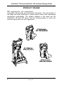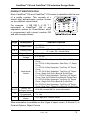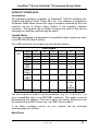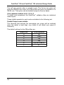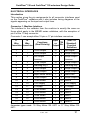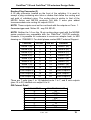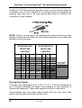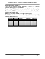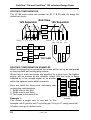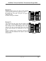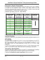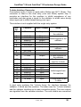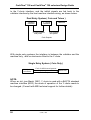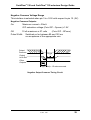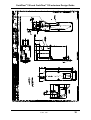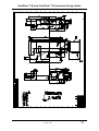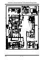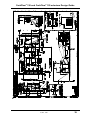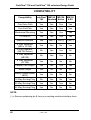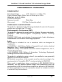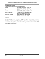
1
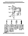
The
CASHFLOW® 126 AND 129
4-WAY AND 8-WAY SELECTORS
DESIGN GUIDE
26043 G3
709623001
CashFlow® 126 and CashFlow® 129 selectors Design Guide
Published by :
MEI
Internet: http://www.meigroup.com
For further information on issues in other languages please write to the
Technical Communications Manager at the above address.
CashFlow® 126 and CashFlow® 129 selectors Design Guide
© , MEI UK International Ltd., 1998. All rights reserved
Except as permitted under the relevant local legislation, no part of this
publication may be copied, transmitted, transcribed, or distributed in any
form or by any means, or stored in a database or retrieval system, or
translated in any language (natural or computer), without the prior written
permission of MEI.
MEI®, CashFlow® and the MEI device are registered trademarks.
©, MEI., 1998.
MEI reserves the right to change the product or the product specifications
at any time. While every effort has been made to ensure that the
information in this publication is accurate, MEI disclaims any liability for
any direct or indirect losses (howsoever caused) arising out of use or
reliance on this information.
This document does not necessarily imply product availability.
Part number: 709623001
This edition (February 1998 )
ii
Printed in the United Kingdom.
©, MEI., 1998
CashFlow® 126 and CashFlow® 129 selectors Design Guide
TABLE OF CONTENTS
SAFETY
1
Warning . . . . . . . . . . . . . . . . . . . . . . . . . . . . . . . . . . . . . . . . . . . . . . . . . . . . . . . . . . . . . . . . . . . . . . . . . . . . . . . . . . . . . 1
Caution . . . . . . . . . . . . . . . . . . . . . . . . . . . . . . . . . . . . . . . . . . . . . . . . . . . . . . . . . . . . . . . . . . . . . . . . . . . . . . . . . . . . . . 1
Maximum Operating Voltage . . . . . . . . . . . . . . . . . . . . . . . . . . . . . . . . . . . . . . . . . . . . . . . . . . . . . . . 1
Dangerous Environments . . . . . . . . . . . . . . . . . . . . . . . . . . . . . . . . . . . . . . . . . . . . . . . . . . . . . . . . . . . 1
Disposal of Product . . . . . . . . . . . . . . . . . . . . . . . . . . . . . . . . . . . . . . . . . . . . . . . . . . . . . . . . . . . . . . . . . . . . 1
Conformance to International Standards . . . . . . . . . . . . . . . . . . . . . . . . . . . . . . . . . . . . . . 1
Safety . . . . . . . . . . . . . . . . . . . . . . . . . . . . . . . . . . . . . . . . . . . . . . . . . . . . . . . . . . . . . . . . . . . . . . . . . . . . . . . . . . . . . . . . 1
PRODUCT RANGE . . . . . . . . . . . . . . . . . . . . . . . . . . . . . . . . . . . . . . . . . . . . . . . . . . . . . . . . . . . . . . . . . . . . . . . . 2
PRODUCT IDENTIFICATION . . . . . . . . . . . . . . . . . . . . . . . . . . . . . . . . . . . . . . . . . . . . . . . . . . . . . . . . . 3
PRODUCT OPTIONS; FRONT PLATES . . . . . . . . . . . . . . . . . . . . . . . . . . . . . . . . . . . . . . . . . 4
PRODUCT OPTIONS; REJECT COVERS . . . . . . . . . . . . . . . . . . . . . . . . . . . . . . . . . . . . . . 5
PRODUCT BUILD OPTIONS . . . . . . . . . . . . . . . . . . . . . . . . . . . . . . . . . . . . . . . . . . . . . . . . . . . . . . . . . . 6
PRODUCT FEATURES . . . . . . . . . . . . . . . . . . . . . . . . . . . . . . . . . . . . . . . . . . . . . . . . . . . . . . . . . . . . . . . . . . 7
DESCRIPTION & OPERATION . . . . . . . . . . . . . . . . . . . . . . . . . . . . . . . . . . . . . . . . . . . . . . . . . . . . . . . 8
Introduction . . . . . . . . . . . . . . . . . . . . . . . . . . . . . . . . . . . . . . . . . . . . . . . . . . . . . . . . . . . . . . . . . . . . . . . . . . . . . . . . 8
Description . . . . . . . . . . . . . . . . . . . . . . . . . . . . . . . . . . . . . . . . . . . . . . . . . . . . . . . . . . . . . . . . . . . . . . . . . . . . . . . . . 8
Operation . . . . . . . . . . . . . . . . . . . . . . . . . . . . . . . . . . . . . . . . . . . . . . . . . . . . . . . . . . . . . . . . . . . . . . . . . . . . . . . . . . . 8
PRODUCT OPERATION . . . . . . . . . . . . . . . . . . . . . . . . . . . . . . . . . . . . . . . . . . . . . . . . . . . . . . . . . . . . . . . . 9
Accepted Coins . . . . . . . . . . . . . . . . . . . . . . . . . . . . . . . . . . . . . . . . . . . . . . . . . . . . . . . . . . . . . . . . . . . . . . . . . . 9
Inhibited Coins . . . . . . . . . . . . . . . . . . . . . . . . . . . . . . . . . . . . . . . . . . . . . . . . . . . . . . . . . . . . . . . . . . . . . . . . . . . 9
Rejected Coins . . . . . . . . . . . . . . . . . . . . . . . . . . . . . . . . . . . . . . . . . . . . . . . . . . . . . . . . . . . . . . . . . . . . . . . . . . . 9
Signals to and from the machine . . . . . . . . . . . . . . . . . . . . . . . . . . . . . . . . . . . . . . . . . . . . . . . . . 9
Routing . . . . . . . . . . . . . . . . . . . . . . . . . . . . . . . . . . . . . . . . . . . . . . . . . . . . . . . . . . . . . . . . . . . . . . . . . . . . . . . . . . . . . . 9
Multi-Pulse . . . . . . . . . . . . . . . . . . . . . . . . . . . . . . . . . . . . . . . . . . . . . . . . . . . . . . . . . . . . . . . . . . . . . . . . . . . . . . . . . 9
PRODUCT OPERATION, ELECTRICAL. . . . . . . . . . . . . . . . . . . . . . . . . . . . . . . . . . . . . . . 10
Validator Connector 1, Machine Interface . . . . . . . . . . . . . . . . . . . . . . . . . . . . . . . . . . 10
Validator Connector 2, CF126 / 129 Separator . . . . . . . . . . . . . . . . . . . . . . . . . . . 10
Validator Connector 3, Routing Plug . . . . . . . . . . . . . . . . . . . . . . . . . . . . . . . . . . . . . . . . . . 10
Validator Connector 4, Dynamic Route Inhibit . . . . . . . . . . . . . . . . . . . . . . . . . . . 11
Validator Connector 5, Serial Port (Future use only) . . . . . . . . . . . . . . . . . . . 11
Validator Connector 6, (Future use only) . . . . . . . . . . . . . . . . . . . . . . . . . . . . . . . . . . . . 11
Rotary Data and 4 Way DIL Teach Switches . . . . . . . . . . . . . . . . . . . . . . . . . . . . . 11
Diagnostic LED . . . . . . . . . . . . . . . . . . . . . . . . . . . . . . . . . . . . . . . . . . . . . . . . . . . . . . . . . . . . . . . . . . . . . . . . 11
Pre-Gate Strobe . . . . . . . . . . . . . . . . . . . . . . . . . . . . . . . . . . . . . . . . . . . . . . . . . . . . . . . . . . . . . . . . . . . . . . . 11
Post-Gate Strobes . . . . . . . . . . . . . . . . . . . . . . . . . . . . . . . . . . . . . . . . . . . . . . . . . . . . . . . . . . . . . . . . . . . . 11
PRODUCT INTERFACES . . . . . . . . . . . . . . . . . . . . . . . . . . . . . . . . . . . . . . . . . . . . . . . . . . . . . . . . . . . . . 12
Introduction . . . . . . . . . . . . . . . . . . . . . . . . . . . . . . . . . . . . . . . . . . . . . . . . . . . . . . . . . . . . . . . . . . . . . . . . . . . . . . 12
Parallel Mode . . . . . . . . . . . . . . . . . . . . . . . . . . . . . . . . . . . . . . . . . . . . . . . . . . . . . . . . . . . . . . . . . . . . . . . . . . . 12
...........................................................................................
©, MEI., 1998
iii
CashFlow® 126 and CashFlow® 129 selectors Design Guide
Multi-Pulse . . . . . . . . . . . . . . . . . . . . . . . . . . . . . . . . . . . . . . . . . . . . . . . . . . . . . . . . . . . . . . . . . . . . . . . . . . . . . . . 13
Coin validation Inhibits A, B, C, D, E, F . . . . . . . . . . . . . . . . . . . . . . . . . . . . . . . . . . . . . . 13
Parallel Output mode inhibits . . . . . . . . . . . . . . . . . . . . . . . . . . . . . . . . . . . . . . . . . . . . . . . . . . . . 13
Coin Output Common Line . . . . . . . . . . . . . . . . . . . . . . . . . . . . . . . . . . . . . . . . . . . . . . . . . . . . . . . 13
Binary Coded Output ( BCO ) . . . . . . . . . . . . . . . . . . . . . . . . . . . . . . . . . . . . . . . . . . . . . . . . . . . . 14
Coin Validation Inhibits A, B, C, D, E, F . . . . . . . . . . . . . . . . . . . . . . . . . . . . . . . . . . . . . 14
Binary Coded Output Mode Inhibits . . . . . . . . . . . . . . . . . . . . . . . . . . . . . . . . . . . . . . . . . . . 15
Auto Mode Parallel or BCO Selection . . . . . . . . . . . . . . . . . . . . . . . . . . . . . . . . . . . . . . . . 15
ELECTRICAL INTERFACES . . . . . . . . . . . . . . . . . . . . . . . . . . . . . . . . . . . . . . . . . . . . . . . . . . . . . . . . 16
Introduction . . . . . . . . . . . . . . . . . . . . . . . . . . . . . . . . . . . . . . . . . . . . . . . . . . . . . . . . . . . . . . . . . . . . . . . . . . . . . . 16
Connector 1, Machine Interface. . . . . . . . . . . . . . . . . . . . . . . . . . . . . . . . . . . . . . . . . . . . . . . . . 16
Connector 2, Separator . . . . . . . . . . . . . . . . . . . . . . . . . . . . . . . . . . . . . . . . . . . . . . . . . . . . . . . . . . . . 17
Connector 3, Routing Plug. . . . . . . . . . . . . . . . . . . . . . . . . . . . . . . . . . . . . . . . . . . . . . . . . . . . . . . . 18
Connector 4, Dynamic Route Inhibit . . . . . . . . . . . . . . . . . . . . . . . . . . . . . . . . . . . . . . . . . 19
Coin Exit Priorities . . . . . . . . . . . . . . . . . . . . . . . . . . . . . . . . . . . . . . . . . . . . . . . . . . . . . . . . . . . . . . . . . . . . 19
Connector 5, Serial Interface . . . . . . . . . . . . . . . . . . . . . . . . . . . . . . . . . . . . . . . . . . . . . . . . . . . . . 19
Y-chute Interface Connector . . . . . . . . . . . . . . . . . . . . . . . . . . . . . . . . . . . . . . . . . . . . . . . . . . . . . 20
TYPICAL ELECTRICAL CIRCUITS . . . . . . . . . . . . . . . . . . . . . . . . . . . . . . . . . . . . . . . . . . . . . . . 22
Coin Output Electrical Specification . . . . . . . . . . . . . . . . . . . . . . . . . . . . . . . . . . . . . . . . . . . 22
Absolute Maximum Ratings . . . . . . . . . . . . . . . . . . . . . . . . . . . . . . . . . . . . . . . . . . . . . . . . . . . . . . 22
Electrical Characteristics . . . . . . . . . . . . . . . . . . . . . . . . . . . . . . . . . . . . . . . . . . . . . . . . . . . . . . . . . . 22
Output Common Specification . . . . . . . . . . . . . . . . . . . . . . . . . . . . . . . . . . . . . . . . . . . . . . . . . . 23
Negative Common Voltage Range . . . . . . . . . . . . . . . . . . . . . . . . . . . . . . . . . . . . . . . . . . . . 24
Positive Common Voltage Range . . . . . . . . . . . . . . . . . . . . . . . . . . . . . . . . . . . . . . . . . . . . . 25
Binary Coded Output (BCO) . . . . . . . . . . . . . . . . . . . . . . . . . . . . . . . . . . . . . . . . . . . . . . . . . . . . . . 26
Coin Inhibits . . . . . . . . . . . . . . . . . . . . . . . . . . . . . . . . . . . . . . . . . . . . . . . . . . . . . . . . . . . . . . . . . . . . . . . . . . . . . 26
MECHANICAL INTERFACE DRAWINGS . . . . . . . . . . . . . . . . . . . . . . . . . . . . . . . . 27
COIN ROUTING . . . . . . . . . . . . . . . . . . . . . . . . . . . . . . . . . . . . . . . . . . . . . . . . . . . . . . . . . . . . . . . . . . . . . . . . . . . 35
Coin Output Signals . . . . . . . . . . . . . . . . . . . . . . . . . . . . . . . . . . . . . . . . . . . . . . . . . . . . . . . . . . . . . . . . . 35
Route Input Lines . . . . . . . . . . . . . . . . . . . . . . . . . . . . . . . . . . . . . . . . . . . . . . . . . . . . . . . . . . . . . . . . . . . . . 35
ROUTING CONFIGURATION . . . . . . . . . . . . . . . . . . . . . . . . . . . . . . . . . . . . . . . . . . . . . . . . . . . . 36
CashFlow® 4-Way Separator . . . . . . . . . . . . . . . . . . . . . . . . . . . . . . . . . . . . . . . . . . . . . . . . . . . . . 36
CashFlow® 129 8-Way Separator . . . . . . . . . . . . . . . . . . . . . . . . . . . . . . . . . . . . . . . . . . . . . . 36
ROUTING CONFIGURATION EXAMPLES . . . . . . . . . . . . . . . . . . . . . . . . . . . . . . . . . . . . 37
COMPATIBILITY . . . . . . . . . . . . . . . . . . . . . . . . . . . . . . . . . . . . . . . . . . . . . . . . . . . . . . . . . . . . . . . . . . . . . . . . . . 38
PERFORMANCE STANDARDS . . . . . . . . . . . . . . . . . . . . . . . . . . . . . . . . . . . . . . . . . . . . . . . . . 39
ELECTRO MECHANICAL CONFORMANCE . . . . . . . . . . . . . . . . . . . . . . . . . . . . . . . . . 39
COMPLIANCE CLASSIFICATIONS . . . . . . . . . . . . . . . . . . . . . . . . . . . . . . . . . . . . . . . . . . . . . . 40
Electro-Mechanical Conformance . . . . . . . . . . . . . . . . . . . . . . . . . . . . . . . . . . . . . . . . . . . . . . 40
Safety . . . . . . . . . . . . . . . . . . . . . . . . . . . . . . . . . . . . . . . . . . . . . . . . . . . . . . . . . . . . . . . . . . . . . . . . . . . . . . . . . . . . . . 40
iv
©, MEI., 1998
CashFlow® 126 and CashFlow® 129 selectors Design Guide
Flammability . . . . . . . . . . . . . . . . . . . . . . . . . . . . . . . . . . . . . . . . . . . . . . . . . . . . . . . . . . . . . . . . . . . . . . . . . . . . . 40
Power Supply Input Protection . . . . . . . . . . . . . . . . . . . . . . . . . . . . . . . . . . . . . . . . . . . . . . . . . . 40
Mechanical Parts . . . . . . . . . . . . . . . . . . . . . . . . . . . . . . . . . . . . . . . . . . . . . . . . . . . . . . . . . . . . . . . . . . . . . 41
Mean coins between failures (MCBF) . . . . . . . . . . . . . . . . . . . . . . . . . . . . . . . . . . . . . . . . 41
First Year Failure Rate . . . . . . . . . . . . . . . . . . . . . . . . . . . . . . . . . . . . . . . . . . . . . . . . . . . . . . . . . . . . . . 41
Coin Acceptance . . . . . . . . . . . . . . . . . . . . . . . . . . . . . . . . . . . . . . . . . . . . . . . . . . . . . . . . . . . . . . . . . . . . . . 41
Coin Sizes . . . . . . . . . . . . . . . . . . . . . . . . . . . . . . . . . . . . . . . . . . . . . . . . . . . . . . . . . . . . . . . . . . . . . . . . . . . . . . . 41
Coin Acceptance Rate . . . . . . . . . . . . . . . . . . . . . . . . . . . . . . . . . . . . . . . . . . . . . . . . . . . . . . . . . . . . . . 41
Fraud Performance . . . . . . . . . . . . . . . . . . . . . . . . . . . . . . . . . . . . . . . . . . . . . . . . . . . . . . . . . . . . . . . . . . 41
ENVIRONMENTAL PERFORMANCE . . . . . . . . . . . . . . . . . . . . . . . . . . . . . . . . . . . . . . . . . . . 42
Temperature Range . . . . . . . . . . . . . . . . . . . . . . . . . . . . . . . . . . . . . . . . . . . . . . . . . . . . . . . . . . . . . . . . . 42
Humidity Range . . . . . . . . . . . . . . . . . . . . . . . . . . . . . . . . . . . . . . . . . . . . . . . . . . . . . . . . . . . . . . . . . . . . . . . . 42
Thermal shock . . . . . . . . . . . . . . . . . . . . . . . . . . . . . . . . . . . . . . . . . . . . . . . . . . . . . . . . . . . . . . . . . . . . . . . . . 42
TRANSPORTATION . . . . . . . . . . . . . . . . . . . . . . . . . . . . . . . . . . . . . . . . . . . . . . . . . . . . . . . . . . . . . . . . . . . . . 43
LIQUID . . . . . . . . . . . . . . . . . . . . . . . . . . . . . . . . . . . . . . . . . . . . . . . . . . . . . . . . . . . . . . . . . . . . . . . . . . . . . . . . . . . . . . . . . 43
MEI MAIN AND REGIONAL OFFICES . . . . . . . . . . . . . . . . . . . . . . . . . . . . . . . . . . . . . 49
©, MEI., 1998
v
CashFlow® 126 and CashFlow® 129 selectors Design Guide
vi
©, MEI., 1998
CashFlow® 126 and CashFlow® 129 selectors Design Guide
SAFETY
Warning
Before cleaning, servicing, removing or replacing CashFlow® units,
ALWAYS SWITCH OFF or ISOLATE the ELECTRICITY SUPPLY to the
machine.
Caution
This guide is for use only by personnel trained to carry out electrical
installation.
Dangerous Environments
Do not operate the unit in the presence of flammable gasses or fumes, or
after the entry of fluid into the machine.
Disposal of Product
If necessary, always dispose of defective units according to local
regulations.
Conformance to International Standards
When installed and operated according to the instructions provided for the
particular unit, CashFlow® products meet the applicable national and
international safety standards for any country in which they are used.
Safety
All electrical connections to the product must be rated according to the
requirements for “Accessible SELV” circuits as defined in EN60335-1.
The product is therefore suitable for use in a class 2 (non-earthed or
non-grounded ) appliance.
Over current protection is not included in the product and should be
provided as part of the machine. The recommended fuse value at the
rated supply of 12V is:
3A Slow blow (to EN60127)
Other protection methods may be used providing their over current
characteristics remain within the overall operating characteristics of the
above fuse.
©, MEI., 1998
1
CashFlow® 126 and CashFlow® 129 selectors Design Guide
PRODUCT RANGE
MEI manufactures coin mechanisms
compatible with gaming and amusement machines. The functionality of
the range has been enhanced to match market needs while maintaining
mechanical compatibility. The product detailed in this book are the
CashFlow® 126 and 129 series. Use the following pages to check you
have the right product for your application.
2
©, MEI, 1998
CashFlow® 126 and CashFlow® 129 selectors Design Guide
PRODUCT IDENTIFICATION
Each CashFlow® 126 and CashFlow® 129 variant is identified with the use
of a profile number. This consists of a
twelve digit alphanumeric number located
on the validator coinset label.
For example: J GB 002 L V 00 T 3
represents a CashFlow® 126 4 way
separation system for Great Britain, which
is programmed with coinset number 002
and also accepts tokens.
Digit
Description
1
Product Code
2&3
Country Code
4,5 & 6 Coinset Number
Operating
7
Voltage
8
9 & 10
11
12
Mechanical
Variant
Factory Set
Software options
Tokens
Programmed
MEI CashFlow®
Series
Available Options
J = CF126
S = CF129
For example; GB = Britain, DE = Germany,
IT = Italy, ZA = South Africa
001 to 999
L = 12v DC
L = CF126 4 Way Separator, Side Entry “A” Reject
Cover
N = CF126 4 Way Separator, Side Entry “C” Reject
Cover
V = CF126 4 Way Separator, Top Entry “B” Reject
Cover
G = CF126 4 Way Separator, Top Entry “B” Reject
Cover, Single Coin Entry Bezel & Guide Plate
H = CF126 4 Way Separator, Top Entry “B” Reject
Cover, Dual Coin/Token Entry Bezel & Guide Plate
P = CF129 8 Way Separator, Top Entry “B” Reject
Cover, Single Coin Entry Bezel & Guide Plate
R = CF129 8 Way Separator, Top Entry “B” Reject
Cover, Dual Coin / Token Entry Bezel & Guide Plate
00 to 99 (contact MEI for more information)
0 = No
T = Yes
3 = CashFlow® Product Series
More information is available on the 3 type of reject cover ( A, B and C ) in
Product Options; Reject Covers.
©, MEI., 1998
3
CashFlow® 126 and CashFlow® 129 selectors Design Guide
PRODUCT OPTIONS; FRONT PLATES
4
©, MEI., 1998
CashFlow® 126 and CashFlow® 129 selectors Design Guide
PRODUCT OPTIONS; REJECT COVERS
©, MEI., 1998
5
CashFlow® 126 and CashFlow® 129 selectors Design Guide
PRODUCT BUILD OPTIONS
6
©, MEI., 1998
CashFlow® 126 and CashFlow® 129 selectors Design Guide
DESCRIPTION & OPERATION
Introduction
This section describes the CashFlow® 126 with a 4 way separator and the
CashFlow® 129 with an 8 way separator system.
Description
The CashFlow® 126 and 129 system range of products are electronic coin
and token handling systems for use in gaming and amusement machines.
The CashFlow® 126 can validate up to 14 coins coins and 2 tokens. The
126 product can separate the accepted coins into 4 ways and the 129
product 8 ways.
Operation
Coin validation parameters are factory programmed for optimum
acceptance of up to 14 coins and 2 tokens When a coin or token is
inserted the validator senses a range of parameters to see if it recognises
the coin/token as part of its pre-programmed set.
If variations are required to the programmed coin set please refer to the
CashFlow® 126 and 129 Operators Handbook for details.
NOTE: In the table below the features of the CF126 Token product are
shown separartely from the CF126. In reality this is one CF126 product,
but are shown here to indicate the availability of profile options,
particularly regarding dual and single coin entry.
©, MEI., 1998
7
CashFlow® 126 and CashFlow® 129 selectors Design Guide
Product Features
STD = Available as Standard Feature
N/A = Not Applicable
OPT = Optional
Features
CF129 CF126Tkn CF126
Number of Active Coins
Up to 16 Up to 16
Up to 16
Number of Active Tokens
2
2
2
Number of Pre-programmed Tokens
Up to 16 Up to 16
0
Operating Voltage
12V D.C. 12V D.C. 12V D.C.
Number of Coin Outputs
6
6
6
(Parallel mode)
Individual Electronic Coin Inhibits
6
6
6
Parallel Interface (Industry standard)
STD
STD
STD
Binary Coded Output B.C.O (BACTA
STD
STD
STD
Standard)
Auto Mode (Parallel / B.C.O. Interface)
STD
STD
STD
4 Way Separator
N/A
STD
STD
8 Way Separator
STD
N/A
N/A
Token Teaching
STD
STD
STD
Token Group Select
STD
STD
N/A
LED Diagnostics
STD
STD
STD
Default Route (Programmable)
STD
STD
STD
Routing Plug
STD
STD
STD
Alarm Output Feature
STD
STD
STD
Side Entry
N/A
OPT
OPT
Top Entry
STD
STD
STD
Coin Only Entry Bezel
OPT
OPT
STD
Dual Coin/Token Entry Bezel
OPT
STD
OPT
Long Channel Mounted
STD
N/A
N/A
Manifold
STD
N/A
N/A
Tube Collar
STD
N/A
N/A
Coinless Programming
STD
STD
STD
Market Application
AWP AWP/SWP AWP/SWP
8
©, MEI., 1998
CashFlow® 126 and CashFlow® 129 selectors Design Guide
PRODUCT OPERATION
Accepted Coins
If a coin or token is recognised by the validator the accept gate will then
be activated and the coin/token routed along the accept path to enter the
separator which consists of a number of solenoid operated gates to route
the coin/token to a pre-programmed exit.
The CashFlow® validator has the capability to sense the direction of a
coin. An alarm output will be given if a coin does not follow the correct
validation sequence.
Inhibited Coins
Acceptance of one or more coin types can be inhibited, causing them to
be rejected. This can be done by using the coin inhibit lines of the
validator machine interface connector 1 or by programming the validator
to reject specific coin types.
Rejected Coins
The validator will reject any coin/token that does not match
pre-programmed limits, or, if no power is supplied to the validator, the
accept gate will remain closed and the coin will be routed via the reject
route.
If a coin or token jams at the entry point, it can be freed by opening the
validator reject flap which releases the coin to the reject path. Side entry
mechanisms fitted to the front plates have an in built reject button that
opens the validator reject flap when pressed.
The host machine is required to provide a suitable mounting facility for
top entry versions.
Signals to and from the machine
Communication between the validator and the machine is made through
the validator machine interface and the Y-chute interface connector (dual
coin/token entry version only).
Once through the validator, the value of the accepted coin is signalled
directly to the machine using the appropriate coin output line (or lines in
BCO mode).
Multi-Pulse
Factory set option designed for backward compatibility gives a GB 50p
coin output (on a GB profile) four times on validation of a GB £2 coin Only
in parallel output mode.
©, MEI., 1998
9
CashFlow® 126 and CashFlow® 129 selectors Design Guide
PRODUCT OPERATION, ELECTRICAL.
Validator Connector 1, Machine Interface
The interface to the machine is provided by Connector 1 of the validator.
The functions provided are: Coin outputs A, B, C, D, E, F. The unit will
operate in one of three Coin Output modes:
Fixed Parallel.
Fixed Binary Coded Output (BCO).
Automatic - Selects BCO or Parallel Interfaces.
More detail on these modes are given later.
Validator Connector (2), CF126 / 129 Separator
This connector is used to connect the validator to the separator. No
customer connections are available on this port. ME Series, Active 126
and high security separators are not compatible with this interface and
must not be connected, otherwise damage to the validator may result.
Validator Connector (3), Routing Plug
This connector is used by the customer to control the separator. Once it is
fitted to the product all factory set routing will be overridden and all routing
will be controlled by the routing plug. The extra two pins on this routing
plug allow for additional coin positions, G and H, to be accommodated.
Validator Connector (4), Dynamic Route Inhibit
This is a 9 pin connector which is an input from the machine to the
validator and its function is to divert coin routing. When a specific exit is
full with coins, the host machine sends a signal to the validator which will
direct future coins to an overflow route.
10
©, MEI., 1998
CashFlow® 126 and CashFlow® 129 selectors Design Guide
Validator Connector (5), Serial Port (Future use only)
This 10 pin connector, accessible from the bottom of the validator,
provides for a potential serial communication to a service tool. At present
this connector serves no function.
Customers should not connect anything to this connector.
Validator Connector (6), (Future use only)
A 6-way connector used for a MEI® Route Alpha hand held service tool.
At present this connector serves no function.
Customers should not connect anything to this connector.
Rotary Data and 4 Way DIL Teach Switches
In place of the option links used on an ME126 and ME129 a rotary data
switch and a 4-way DIL switch have been provided. These are accessible
through the opening in the reject cover.
The rotary data switch will enable data input to the teach functions i.e.
Token Selection.
The 4-way DIL switch can be used to enable or disable the alarm by using
switch 1 of the DIL switch or various teach functions which are accessed
via switches 2, 3 & 4.
Diagnostic LED
The LED displays a sequence of flash codes to indicate the current
operation of the validator, and can be used for fault diagnosis when
inserting coin or when teaching functions as shown below.
Flash Code Sequence:
Constantly ON Validator power on
1 Flash
Coin accepted / Reject lever pressed
2 Flashes
Coin not recognised and rejected
3 Flashes
Coin rejected by validator 4th sensor
4 Flashes
Coin recognised but not accepted due
to inhibit setting
Pre-Gate Strobes
This is an integral part of the validator which detects obstructions around
the accept gate. If an obstruction is detected then coin acceptance is
inhibited.
Post-Gate Strobes
The strobes are used for added security to the validator. These detect
coins which enter the validator using the wrong direction e.g. from the
bottom of the validator upwards. If this movement is detected the alarm
will sound.
©, MEI., 1998
11
CashFlow® 126 and CashFlow® 129 selectors Design Guide
PRODUCT CONFIGURATION
Using the Rotary Data Switch and the 4-Way DIL Switches the product
can be re-configured.
Further details regarding the settings shown below can be obtained from
the CashFlow® 126 and 129 Operators Handbook.
4-Way DIL Switches
1
2
3
4
OFF
ON
X
X
X
X
X
X
X
X
X
X
X
X
OFF
OFF
ON
OFF
ON
ON
OFF
OFF
OFF
OFF
ON
ON
X
X
X
X
X
X
ON
ON
ON
OFF
ON
OFF
ON
OFF
OFF
ON
ON
OFF
Configuration
Mode Selected
Alarm Dis-abled
Alarm Enabled
Default Overflow Route
Machine Interface Type
Inhibit Coin/Token Teach
Enable Coin/Token Teach
Token Group Select for
Channel 0
Self Teach a Token into
Channel 0
Token Group Select for
Channel 1
Self Teach a Token into
Channel 1
Discriminator Node ID Select
Fraud Defence Teach to
Channel 0
Normal Operation
Normal Operation
Rotary Switch
position/s
required
X
X
0-7
C-F
0-F
0-F
0-D
E-F
0-D
E-F
0-6
E-F
X
X
To commence any changes firstly the power should be removed, the
required settings made on the rotary switch, the DIL switch settings are
set and then the unit is powered up again. At this point the LED will start
flashing. Returning the DIL switches to either all OFF or all ON will commit
the changes to non-volatile memory.
Tests should then be conducted to confirm that the changes are
satisfactory, including the relevant flash sequences of the LED, as
described later.
If a teach mode is entered inadvertently then either switch off power or
just leave for 30 seconds (when the LED will stop flashing), otherwise a
teach function may be set that was not intended.
12
©, MEI., 1998
CashFlow® 126 and CashFlow® 129 selectors Design Guide
PRODUCT INTERFACES
Introduction
The standard interfaces available on CashFlow® 126/129 validators are
Parallel and Binary Coded Output (B.C.O.). The validator is supplied in
Automatic Mode which senses the type of interface selected by the host
machine via pin 8 (Output Mode Select) of the machine interface
connector. The product can be taught to ignore the state of this line by
changing the machine interface type as above.
Parallel Mode
This type of interface is a standard 6 coin parallel output interface as used
in the ME126/129 (Dual Polarity).
For a GB profile the coin outputs are activated as follows:
Alarm
O/P
Coins
5p
Token
10p
20p
50p
(Old)
50p
(New)
£1
(1983)
£2
Enabled Outputs
A
3
Coin Output
B
C
D
E
F
3
3
3
3
3
3
3
3
3
3
Multi
Pulse
(4
pulses)
3
3
The coin outputs for A and C can be combined ( e.g. A + C, B, D, E, F ) to
give compatibility with 5 coin ME126B1 validators. This option is set by
programming the validator. The coin outputs are factory defined but can
be modified via an MEI service tool, e.g. MEI® Service Alpha.
If an alarm condition occurs all coin outputs will be activated
simultaneously for >600ms.
Multi-Pulse
©, MEI., 1998
13
CashFlow® 126 and CashFlow® 129 selectors Design Guide
This will only operate when in parallel mode. This factory set option will
pulse the GB 50p coin output (of a GB profile) four times on validation of a
GB £2 coin. This option can be disabled using the Service Alpha.
Coin validation Inhibits A, B, C, D, E, F
To inhibit coin acceptance the CashFlow® validator offers six individual
inhibit inputs.
These inhibits operate for each mode as detailed in the following text.
Parallel Output mode inhibits
The channels that activate the associated coin output will be inhibited
when the inhibit is held High, (e.g. Inhibit A will inhibit coin output A
channels).
The default settings for the GB profiles are:
14
Inhibit Line
Coins Inhibited
A
5p
B
Token
C
10p
D
20p
E
50p old & new £2
F
£1
©, MEI., 1998
CashFlow® 126 and CashFlow® 129 selectors Design Guide
Coin Output Common Line
This line allows for operation with positive or negative common systems.
The interface self-configures by sensing the output common voltage
supplied by the machine on the coin output common line, (pin 2 for a 15
way machine interface connector, or pin 3 for a 17 way connector).
All potentials are relative to the 0 volt return line to the machine. pin 11 for
a 15 way connector and pin 12 for a 17 way machine interface connector.
Negative common operation is selected when pin 2 output common is 0
volts or negative with respect to pin 11.
Positive common is selected when pin 2 is more positive than +7 volts
with respect to pin 11.
Binary Coded Output ( BCO )
Defined by the validator coin output map. When in BCO mode coin output
A is permanently set active to indicate that the BCO feature is available.
Coin output A will have a high impedance (approx. 1M Ohm to 0v) if coin
output common is allowed to float. If an alarm condition occurs coin
outputs B, D, E and F will be activated.
Enabled
Outputs
Coins
5p
10p
20p
50p (Old)
50p (New)
A
1
1
1
1
1
£1 (1983)
£2
Token
Alarm Output
1
1
1
1
Coin Output
B
C
0
1
1
1
0
1
1
1
0
1
1
1
0
1
1
1
1
0
D
0
1
0
0
1
E
0
0
1
0
0
F
0
0
1
1
1
0
1
1
1
1
1
1
1
0
1
0
1
Coin Validation Inhibits A, B, C, D, E, F
To inhibit coin acceptance the CashFlow® validator offers six individual
inhibit inputs.
These inhibits operate for each mode as detailed in the following text.
©, MEI., 1998
15
CashFlow® 126 and CashFlow® 129 selectors Design Guide
Binary Coded Output Mode Inhibits
The channels inhibited, for a given inhibit line going high are factory set by
the validators coin inhibit map option. When inhibit (A to F) is active, then
coins for the channels specified in the map will be inhibited. The default
settings for the GB profile are:
Inhibit Line
Coins inhibited
A
£2
B
Token
C
Reserved
D
20p
E
5p, 10p, 50p old & new
F
£1
Automatic Mode - Parallel or BCO Selection
In this mode the status of the output mode input (on pin 8 of the 17 way
connector, or pin 7 for the 15 -way connector of the machine interface)
selects either the parallel or the binary coded output interface standards.
A logic high signal to this pin will select parallel mode, setting pin 8 to a
logic low will select BCO mode. If there is no connection made to pin 8 the
interface will default to parallel mode.
16
©, MEI., 1998
CashFlow® 126 and CashFlow® 129 selectors Design Guide
ELECTRICAL INTERFACES
Introduction
This section gives the pin assignments for all connector interfaces used
on the CashFlow® validators and it also includes timing diagrams of the
signals appearing on the input and output lines.
Connector 1, Machine Interface.
The interface to the validator from the machine is exactly the same as
those which apply to the MS/ME series validators, with the exception of
pin 8 of the 17-way connector.
Connector 1 can accept either 15 pin or 17 pin interface connectors.
17
15
Way
Way
Connector Connector
1
-
A Coin Output
O
(BACTA
Standard)
Function
Definition
1 Ident signal
2
1
B Coin Output
O
2 Accept Output 5
3
2
Coin Output
Common
I
3 Accept Output
Common
4
3
F Coin Output
O
4 Accept Output 1
5
4
Polarising Key 1
-
5 Polarising Key
6
5
E Coin Output
O
6 Accept Output 2
7
6
D Coin Output
O
7 Accept Output 3
8
7
Output Mode Select
I
8 Select Line
9
8
C Coin Output
O
9 Accept Output 4
10
9
C Coin Inhibit
I
10 Inhibit 4
11
10
+12V Supply
I
11 +12V Supply
12
11
0V Supply
I
12 0V Supply
13
12
D Coin Inhibit
I
13 Inhibit 3
14
13
E Coin Inhibit
I
14 Inhibit 2
15
14
F Coin Inhibit
I
15 Inhibit 1
16
15
B Coin Inhibit
I
16 Inhibit 5
17
-
A Coin Inhibit
I
17 Inhibit 6
Functions
(Dual Polarity)
Input
or PIN
Output No.
Connector types used:- 15 Way Molex SIL 6471 or 17 Way Molex SIL
6471.
©, MEI., 1998
17
CashFlow® 126 and CashFlow® 129 selectors Design Guide
Separator Connector (2)
This connector is used for connection to the CashFlow® 126 4 way or
CashFlow® 129 8 way separators only.
Function
Solenoid 3
Pin No. Pin No. Function
1
2
Solenoid 1
Unused
3
4
+12V
Unused
5
6
Solenoid 2
Unused
7
8
Unused
Data
9
10
Ground
Busy
11
12
Ground
Reset
13
14
Ground
Unused
15
16
Ground
V Reference
17
18
+ 5V
+ 12V
19
20
+ 12V
Connector type used:- 20 way Molex DIL 901-42-0020.
WARNING:
Do not connect ME129, ME126 Active or ME126 Security separators to
this product or damage may result.
18
©, MEI., 1998
CashFlow® 126 and CashFlow® 129 selectors Design Guide
Routing Plug Connector (3)
A 22 way connector located on the front of the validator. It is used to
accept a plug containing wire links or diodes that define the routing and
exit path of validated coins. The routing plug is similar to that of the
ME126 Active and ME129 products, but with 2 extra pins added
toaccommodate coin routing for outputs G & H.
NOTE: These outputs must not be confused with the outputs on Conn. 1.
Connector type used: Molex 22 - way DIL 90142.
NOTE: Neither the 14 nor the 18 pin routing plugs used with the MS/ME
series products are compatible with the CashFlow® 126/129 products.
However, it is possible for customers to source an adaptor loom, to MEI
drawing no. 709856001. For detail please contact MEI Technical Support.
Function
Pin No.
Pin No.
Function
Route 7 (B)
1
2
Route 7 (B)
Route 6 (D)
3
4
Route 6 (D)
Route 5 (C)
5
6
Route 5 (C)
Route 4 (b)
7
8
Route 4 (b)
Route 3 (a)
9
10
Route 3 (a)
Route 2 (c)
11
12
Route 2 (c)
Route 1 (d)
13
14
Route 1 (d)
Coin Output A
15
16
Coin Output B
Coin Output C
17
18
Coin Output D
Coin Output E
19
20
Coin Output F
Coin Output G
21
22
Coin Output H
There are 7 exits (pins 1 to 14) labelled route 1 to 7, and 8 coin outputs
(pins 15 to 22) labelled coin output A to H.
GB Coinset Detail
COIN OUTPUT
COIN/TOKEN VALUE
A
B
C
D
E
F
G
H
5P
TOKEN
10P
20P
50P old
1P
50p new
2P
©, MEI., 1998
19
CashFlow® 126 and CashFlow® 129 selectors Design Guide
CashFlow® 126/129 separators provide control over the exit path taken by
a validated coin. This is referred to as routing and is accomplished by
inserting wire links into a 22 way routing plug which is inserted into
connector 3 of the validator.
NOTE: Fitting a routing plug to the validator will overide all factory routing
settings as long as more than one link is fitted between a coin output and
data pin on this connector.
126 ROUTING PLUG
129 ROUTING PLUG
PINOUTS AND
FUNCTIONS
PINOUTS AND
FUNCTIONS
Function Pin
No.
Coin H 22
Coin F 20
Coin D 18
Coin B 16
(Exit ‘d’) 14
(Exit ‘c’) 12
(Exit ‘a’) 10
(Exit ‘b’) 8
Exit C
6
Exit D
4
Exit B
2
Pin Function Functio Pin
No.
n
No.
21 Coin G Coin H 22
19
Coin E Coin F 20
17 Coin C Coin D 18
15
Coin A Coin B 16
13 (Exit ‘d’) Route 1 14
11 (Exit ‘c’) Route 2 12
9 (Exit ‘a’) Route 3 10
7 (Exit ‘b’) Route 4 8
5
Exit C Route 5 6
3
Exit D Route 6 4
1
Exit B Route 7 2
Pin Function
No.
21 Coin G
19
Coin E
17 Coin C
15
Coin A
13 Route 1
11 Route 2
9 Route 3
7 Route 4
5 Route 5
3 Route 6
1 Route 7
Coin Exit Route
Priority Order
Highest
Lowest
Routing Plug Signals
The eight coin output signal lines, A, B, C, D, E, F, G and H correspond to
up to fourteen possible coin types. The mapping of coin channels is
channel set dependent. These lines signal the arrival of valid coins.
Links between the coin output signal inputs and the coin route lines
specify the exit paths to be taken by the coins.
20
©, MEI., 1998
CashFlow® 126 and CashFlow® 129 selectors Design Guide
Route Input Lines - Routes 1-7
The CF129 exit routes are marked as Route (1, 2, 3, 4, 5, 6 & 7) with (8)
being the default exit route, as standard.
Routes 1-7 on CF129 refer to the coin routes 1 to 7, with 1 having high
priority and 7 low priority.
Routes 1-7 on CF126 refer to the 4 coin route outputs A, B, C and D as
shown in the following table.
Note: (d) is the same route as D but has a higher priority.
The CF129 exit routes are marked as Route (1, 2, 3, 4, 5, 6 & 7) with (8)
being the default exit route.
Solenoid 3 Solenoid 2 Solenoid 1
1
1
1
1
0
0
0
0
1
1
0
0
1
1
0
0
0
1
0
1
1
0
1
0
©, MEI., 1998
129 Route
126 Route
1
2
3
4
5
6
7
8
(d)
(c)
(a)
(b)
C
D
B
A
21
CashFlow® 126 and CashFlow® 129 selectors Design Guide
ROUTING CONFIGURATION
The CF126 exits routes are marked as (B, C & D) with (A) being the
default exit route.
129 Separator
End View
126 Separator
Sol 1
Sol 2
Sol 3
EXITS 1 2 3 4 8 7 6 5
EXITS
D
A
(d)
B
C
(a) (b)
(c)
5
8
7
Reject
2
1
6
7
8
4
6
3
2
3
5
D
C
(d)
(c)
4
TOP VIEW
A
(a)
B
(b)
1
ROUTING CONFIGURATION EXAMPLES
When a routing plug is connected the routes will be set up as designated
by the plug links and routing plug outputs.
Where two or more exit routes are specified for a given coin, the highest
priority will be chosen by the validator unless that exit route is being
inhibited by a low voltage signal on its position
within the dynamic route inhibit connector.
P i n
P i n
Here are listed the three most commonly used
routing plug configurations.
1. Single coin to one Exit.
2. Single coin to two Exits.
3. Two coins to the same Exit.
22
Coin H
Coin G
21
20
Coin F
Coin E
19
18
Coin D
Coin C
17
16
Coin B
Coin A
15
14
Route 1 (d)
Route 1 (d)
13
12
Route 2 (c)
Route 2 (c)
11
10
Route 3 (a)
Route 3 (a)
9
8
Route 4 (b)
Route 4 (b)
7
6
Route 5 (C)
Route 5 (C)
5
4
Route 6 (D)
Route 6 (D)
3
2
Route 7 (B)
Route 7 (B)
1
Routing Plug Viewed From Wire Links End
Example 1:Example 1
This shows a single coin to one exit. In this
example coin E goes to exit C by linking pin 19 to pin 11 using a wire link.
All other coins go to default route.
22
©, MEI., 1998
CashFlow® 126 and CashFlow® 129 selectors Design Guide
Example 2:Shows a single coin to two exits. In this example
coin E goes to exit D then overflows to exit C.
By linking pin 19 to pin 13 & pin 14 to pin 12
using wire links.
All other coins go to default.
P i n
P i n
22
Coin H
Coin G
21
20
Coin F
Coin E
19
18
Coin D
Coin C
17
16
Coin B
Coin A
15
14
Route 1 (d)
Route 1 (d)
13
12
Route 2 (c)
Route 2 (c)
11
10
Route 3 (a)
Route 3 (a)
9
8
Route 4 (b)
Route 4 (b)
7
6
Route 5 (C)
Route 5 (C)
5
4
Route 6 (D)
Route 6 (D)
3
2
Route 7 (B)
Route 7 (B)
1
Routing Plug Viewed From Wire Links End
Example 3:This shows how two coins can be routed to the
same exit. In this example coins F and D both
are routed to exit C. By linking pin 20 to pin 5
and pin 18 to pin 6 using diode links (the anode
of the diode should be connected to the coin
pin).
Where a default route is required, teaching the
default route will alleviate the need to use too
many diodes.
©, MEI., 1998
Example 2
P i n
P i n
22
Coin H
Coin G
21
20
Coin F
Coin E
19
18
Coin D
Coin C
17
16
Coin B
Coin A
15
14
Route 1 (d)
Route 1 (d)
13
12
Route 2 (c)
Route 2 (c)
11
10
Route 3 (a)
Route 3 (a)
9
8
Route 4 (b)
Route 4 (b)
7
6
Route 5 (C)
Route 5 (C)
5
4
Route 6 (D)
Route 6 (D)
3
2
Route 7 (B)
Route 7 (B)
1
Routing Plug Viewed From Wire Links End
Example 3
23
CashFlow® 126 and CashFlow® 129 selectors Design Guide
Connector 4, Dynamic Route Inhibit
This direct input from the machine to the front reject cover of the validator
is knows as the Dynamic Route Inhibit. The inhibit placed via this
connector indicates that a specific route is full. To Inhibit a route this has
to be grounded (i.e. active low to inhibit a route).
Connector type used:- 9 pin SIL - AMP 925366.
Route Inhibit
Connector
Pin No.
CF129
CF126
8 Way Separator 4 Way Separator
Exit Route
Exits
Coin Exit
Priorities
1
Divert to Route 1 Exit (d) = Priority 1
HIGHEST
2
Divert to Route 2 Exit (c )= Priority 2
3
Divert to Route 3 Exit (a) = Priority 3
4
Divert to Route 4 Exit (b) = Priority 4
5
Divert to Route 5 Exit C = Priority 5
6
Divert to Route 6 Exit D = Priority 6
7
Divert to Route 7 Exit B = Priority 7
8
Route 8 is the
Default
Exit A is the
Default
9
Ground
Ground
LOWEST
Coin Exit Priorities
If an exit is required to be inhibited, the alternative route/exit must be of a
lower priority.
For example:If a route inhibit is applied to route 5 ( for the 8 way separator or exit C for
the 4 way separator )then routing can only be diverted to routes 6, 7 or 8
the default route on 8 way separators or exits D,B or A for the 4 way
separator.
If route D is required to be diverted to route C on the 126 product then
route 1 (d) should be used, which can then be diverted to any output.
Connector 5, Serial Interface
Provision has been made for future access to a comprehensive interface
facility, but at the present time this connector serves no function.
Customers should not connect anything to this connector.
24
©, MEI., 1998
CashFlow® 126 and CashFlow® 129 selectors Design Guide
Y-chute Interface Connector
Connections to the Y-chute is made with a Molex type 6471 19-way. This
connector is fitted to the dual entry (coin and token) system only. It
provides an interface for the machine to inhibit acceptance of any
coin/token and also gives a signal to the validator to inhibit coins during
token input and to inhibit tokens during coin input.
This interface is not supplied with the single entry system.
Pin
No.
1
Function
Input / Output
Notes
12 Volts
Output
12 volts supply to
the validator
2
3
4
5
6
7
Inhibit F
Inhibit E
Inhibit D
Inhibit C
Polarisation
Inhibit B
Output
Output
Output
Output
Output
8
9
10
Not Used
Not Used
0 Volts
Output
11
0 Volts
Input
12
13
14
15
16
17
18
19
Polarisation
Not Used
Inhibit B
Inhibit C
Inhibit D
Inhibit E
Inhibit F
12 Volts
Input
Input
Input
Input
Input
Input
Inhibit signals to the
validator
Inhibit signals to the
validator
0 volts common to
the validator
0 volts common
input to Y-chute
Inhibit signal from
the machine
12 volts input to the
Y-chute
In dual entry systems the Y-chute forms the interface between the
validator, Y-chute and the machine. The latter uses the Y-chute interface
and the validator interface as its main connection points. The coin outputs
are signalled from the validator interface. The coin inhibits are connected
©, MEI., 1998
25
CashFlow® 126 and CashFlow® 129 selectors Design Guide
to the Y-chute interface, and the inhibit signals are fed back to the
validator interface by the host machine interface wiring, as shown below.
Dual Entry System ( Coin and Token )
Validator
Interface
Y - Chute
Interface
Y-Chute Inhibits
and power
Machine
Coin Inhibits
and power
Coin Outputs
With single entry systems the interface is between the validator and the
machine only, with no electronics fitted to the Y-chute.
Single Entry System ( Coin Only )
Validator
Interface
Coin Inhibits and power
Machine
Coin Outputs
NOTE:
When an old, (pre-March 1997), Y chute is used with a BACTA standard
machine interface (BCO) the mode of operation of the Y chute needs to
be changed. (Consult with MEI technical support for further details).
26
©, MEI., 1998
CashFlow® 126 and CashFlow® 129 selectors Design Guide
ELECTRICAL SPECIFICATION
Voltage Range
Current Consumption;
12V (+ 3V maximum, -2V minimum)
Quiesent (Idle) - 35mA
Coin Flight - 65 mA
Accept Gate only - 800 mA
2 Routing Solenoids - 2,300 mA for 320mS
3 Routing Solenoids - 3000 mA for 320 mS
Coin Output Electrical Specification
A
B
Logical Outputs C
D
E
F
o/p A
o/p B
o/p C
o/p D
o/p E
o/p F
6X
i/p
o
o/p
XOR
Polarity Sense
Output Driver Block
Vcc
4k7
o/p common
1K
10n
56R
Output Circuit Block Diagram
Absolute Maximum Ratings
Output Current
(O/PA) - F)
Maximum Voltage
(O/PA) - F)
©, MEI., 1998
± 30 mA
± 32 V w.r.t. 0V
27
CashFlow® 126 and CashFlow® 129 selectors Design Guide
Output Common Specification
Vcc
R ohms
(470)
Cashflow
126
Outputs
A
B
C Multiplexed
D
Bus
E
F
A
B
C
D
E
F
OutputCom
Rx10
(4k7)
I= 6xVcc/R
(150mA)
Option
Switches
etc.
Strobe 1
Strobe 2
Sample multiplexed implementation - Negative Common Strobe
If output common (OPcom) is left floating then it is possible that the output
configuration could change.
When the OPcom is redefined, then, if the output configuration has to
change, then there is a maximum delay of 15us before the coin outputs
will be valid. Before this time the outputs will be indeterminate.
To prevent this happening a resistor should be added to OPcom to define
the level during the multiplexing off period. The value should be large
enough so as not to interfere with the normal interplexing operation. In this
case the maximum delay between Opcom and coin outputs is 1us.
NOTE: Should an alarm situation be detected, all outputs in parallel mode
will go true. Any multiplexing device must be capable of sinking or
sourcing sufficient current (i.e. 6 x single output current) to keep the
output common voltage within the maximum or minimum specification for
that configuration.
28
©, MEI., 1998
CashFlow® 126 and CashFlow® 129 selectors Design Guide
Negative Common Voltage Range
This interface is selected when pin 3 is <2.5V with respect to pin 12. (0V)
Negative Common Outputs:
On:
Maximum current = 30mA
O/P saturation voltage (Coin O/P - Opcom) <1.5V
Off:
10 uA maximum at 27 volts
Pulse Width:
(Coin O/P - OPcom)
Switched on for between 80 and 120 ms
on acceptance of the appropriate coin.
Output
Common
Output
to be Set
100 ms 10%
+
o/p on
Other
Outputs
o/p off
T(o/p valid) = 15 micro seconds
Negative Output Common Timing Circuit
©, MEI., 1998
29
CashFlow® 126 and CashFlow® 129 selectors Design Guide
Positive Common Voltage Range
Positive Common Operation (O/P Common)
This interface is selected when pin 3 is greater than +4.5 volts with
respect to pin 12. (0V)
Output Common Voltage:
+7 volts to +26 volts with respect to pin 12.
Positive Common Outputs:
On:
Maximum current = 40mA
Saturation voltage (Opcom - Coin O/P) <1.5V
Off:
10uA maximum at +27 volts (Opcom - Coin O/P)
Pulse Width:
Switched on for between 80 and 120ms on
acceptance of appropriate coin.
100ms max
Vsupply
Output
Mode Select
Output
Common
Output A
T (o/p valid)
Coin O/P valid
BCO Output Indication from "Power ON"
30
©, MEI., 1998
CashFlow® 126 and CashFlow® 129 selectors Design Guide
Binary Coded Output (BCO)
BCO mode is indicated by the A output being permanently active. This
indicator can take up to 100 milliseconds to be established from power
up.
In order to ensure reliable operation of the machine the state of this output
should be regularly polled (as the coin validator could be reconfigured
without the power being removed).
As there are often long machine interface leads involved in coin
mechanism interfaces, it is recommended that the coin outputs should be
de-bounced in software to reduce the effect of glitches.
Coin Inhibits
Input voltage to enable channels (logic 0) ) <1.0V
Input voltage to inhibit channels (logic 1) >4.0V
Input impedance
12 Kohms to +5v.
©, MEI., 1998
31
CashFlow® 126 and CashFlow® 129 selectors Design Guide
MECHANICAL INTERFACE DRAWINGS
The following drawings are included in this section:
CF126 Front Plate Dimensions
Drawing Number 32780 Front plate mounting detail.
Drawing Number 32799 Standard front plate dimensions.
Drawing Number 35811 Side entry space envelope.
CF126 Top Entry Mounting Space Envelope
Drawing Number 35812.
CF129 Long Channel Mounting Space Envelope
Drawing Number 35824 Long channel dimensions.
Drawing Number 35954 CF129 system installation dimensions.
(Fitted with Long manifold)
Drawing Number 35961 CF129 system installation dimensions.
(Fitted with Short manifold)
32
©, MEI., 1998
CashFlow® 126 and CashFlow® 129 selectors Design Guide
©, MEI., 1998
33
CashFlow® 126 and CashFlow® 129 selectors Design Guide
34
©, MEI., 1998
CashFlow® 126 and CashFlow® 129 selectors Design Guide
©, MEI., 1998
35
CashFlow® 126 and CashFlow® 129 selectors Design Guide
36
©, MEI., 1998
CashFlow® 126 and CashFlow® 129 selectors Design Guide
©, MEI., 1998
37
CashFlow® 126 and CashFlow® 129 selectors Design Guide
38
©, MEI., 1998
CashFlow® 126 and CashFlow® 129 selectors Design Guide
©, MEI., 1998
39
CashFlow® 126 and CashFlow® 129 selectors Design Guide
COMPATIBILITY
Compatibility
CashFlow® ME126 ME126
Standard Active
126
MS126
& B1
Coin Entry Path
Yes
Yes
Yes
Yes
Coin Exit Path
Yes
Yes
Yes
Yes
Mechanical Mounting
Yes
Yes
Yes
Yes
12 Volts DC
Yes
Yes
Yes
Yes
Machine Interface
Yes
Yes (*)
Yes (*)
Yes (*)
4 Way Separator
(ME or CF126)
Yes
Yes
No
Yes
4 Way Separator
(ME 126 Active)
No
Yes
Yes
No
8 Way Separator
(ME129)
No
Yes
Yes
No
8 Way Separator
(CF129)
Yes
No
No
No
Parallel Coin Output
Yes
Yes
Yes
Yes
Serial Output
Yes
No
No
No
Binary Coded Output
(BCO)
Yes
No
No
No
18 Way Routing Plug
No
Yes
No
Yes
20 Way Routing Plug
Yes
No
Yes
No
22 Way Routing Plug
Yes
No
No
No
NOTE:
(*) = Remove polarising pin 8 from your existing machine interface loom
40
©, MEI., 1998
CashFlow® 126 and CashFlow® 129 selectors Design Guide
PERFORMANCE STANDARDS
POWER SUPPLY
Operating Voltage:
+12V tolerance = (+ 3V) (- 2V)
Supply Voltage Ripple Within Vmin to Vmax up to 100Hz
250mV pk - pk for F>100Hz
Current consumption:
Quiescent current:
35mA Max
Max current:
2.5A Max (4 solenoids active)
COMPLIANCE CLASSIFICATIONS
The product is designed to the following standards for sale into European
markets and will carry the “CE”mark.
Electromagnetic Conformance (EMC)
The product is designed to comply with the following European standards:
EN50082-1 1992 Electromagnetic Compatibility Generic Immunity
Standard
EN55022 1995 Limits and methods of measurement of radio disturbance
characteristics of information technology equipment.
Safety
The product is intended for use in machines which are designed to
comply with;
a) EN60335-1, 3rd Edition, Safety of household and similar electrical
appliances, Part 1, General Requirements.”
b) BS3456, Safety of household and similar electrical appliances, Part 1,
General Requirements.
c) BS EN60950 1992, Safety of Information Technology Equipment,
including electrical business equipment.
The product is suitable for use in a class 2 (non-earthed or non-grounded)
appliance as defined in EN60335.
All electrical connections to the acceptor must be rated according to the
requirements for “Accessible SELV”circuits as defined in EN60335.
When used in applications where compliance to BS EN60950:1992 is
necessary, the host machine power supply must additionally meet the
requirements for SELV limited power supplies as defined in BS EN60950.
For these applications, the coin mechanism should be installed so that it
is external to any fire enclosure.
©, MEI., 1998
41
CashFlow® 126 and CashFlow® 129 selectors Design Guide
Flammability
All major plastic parts will be moulded in materials with a flammability
rating of 94 V-2 / IEC 707 FV2 or better. Some small parts are moulded in
materials with a flammability rating of 94 HB / IEC 707 FH2.
Power Supply Input Protection
Overcurrent protection is not included in the product and must be
provided as part of the machine.
Recommended fuse rating at the rated supply of 12V is:
3A Slow blow EN60127
Other protection methods may be used providing their over current
characteristics remain within the overall operating characteristics of the
above fuse.
Mechanical Parts
The product will not contain mechanically moving parts, or sharp edges,
which can prevent a hazard in normal use.
Coin Sizes
CashFlow® 126 and CashFlow® 129 will be able to validate and route
coins within the following range:
Circular coins, in the range 15mm to 31.5 mm in diameter.
Circular coins, in the range 1.1mm to 3.2mm in thickness.
Faceted coins within the relevant coinsets will also be handled.
Damaged, bent or very distorted coins may not be validated.
Coin Acceptance Rate
The acceptor will validate coins at up to 3 coins per second, when linearly
separated i.e. >330 ms apart. After a coin has been rejected, no further
coins will be accepted for a period of 0.5 seconds. Should a further coin
be entered during this period, the reject period will be reinitiated.
Fraud Performance
Dual post gate strobes are fitted to give protection against COAS and
Strimmer type frauds. A pre-gate strobe is fitted for protection against
“Spoon”fraud.
Provision has been made on the PCB for a COAS detector. If the input is
seen to go active, the alarm will be sounded.
Where machines do not recognise an all outputs ON as an alarm
indication the alarm should be disabled by switching option switch 1 to
OFF, otherwise false credit may be given in the event of a fraud attack.
42
©, MEI., 1998
CashFlow® 126 and CashFlow® 129 selectors Design Guide
ENVIRONMENTAL PERFORMANCE
Temperature Range
Normal operational range
10°C to 40°C
Full operational range 0°C to 60°C
Storage range -10°C to 75°C
Max. rate of change
10°C/hr, non condensing
Humidity Range
Operational10%RH - 90%RH, non condensing
Storage
5%RH to 95%RH, non condensing
% Relative Humidity
100
- 10,95
35, 95
35, 90
75
S
50
F
N
25
F
60, 10
- 10, 10
-20
S
0
20
40
60
75, 10
80
Temperature / Humidity specification
Temperature oC
N = Normal operating range
F = Full operating range
S = Storage range
Thermal shock
Sudden changes of temperature may cause temporary degradation of
performance. For continuous operation and specified performance within
the full operational temperature range, the rate of change of temperature
should not be greater than 10°C per hour, non condensing
Vibration (through machine mounting)
Vibration 0.25g at 5Hz to 500Hz - pseudo random, flat bandwidth
Coin validation will not be affected.
©, MEI., 1998
43
CashFlow® 126 and CashFlow® 129 selectors Design Guide
TRANSPORTATION
The following apply to fully packaged units:
Shock
Half sine, 30g shock, 18ms dur
BS 2011 Part 2.1 EA : 1977
Bump
1000 bumps 6ms duration at 25g
BS 2011 Part 2.1 b : 1977
Drop - Free Fall
2 drops from 1m onto each face
BS 2011 Part 2.1 ED : 1977
Drop and Topple
50mm drop onto each corner
BS2011 Part 2.1 EC : 1977
LIQUID
CashFlow® 100 series validators PCB’s are fitted with splash protection
shields to protect against fluid intrusion. However, prolonged exposure to
a salt laden atmosphere, or liquids which dry onto the surface of the PCB
could cause malfunction.
44
©, MEI., 1998
CashFlow® 126 and CashFlow® 129 selectors Design Guide
MEI MAIN AND REGIONAL OFFICES
WWW.MEIGROUP.COM
©, MEI., 1998
CashFlow® 126 and CashFlow® 129 selectors Design Guide
INDEX
4-Way DIL Switches, 12
4 Way DIL Teach Switch, 11
4 way Separation, 8, 23
Diagnostic LED, 11
Disposal of Product, 1
Dual Entry System, 25
Dual Entry Systems, 24
Dynamic Route Inhibit, 10, 23
8
E
8-Way Separation, 21
8 way Separation, 8, 23
Electrical Interfaces, 17
Electro-mechanical Conformance,
40
Electromagnetic Conformance, 41
Environmental Performance, 44
4
A
Accept Gate, 9
Automatic Mode, 10, 13
F
B
Binary Coded Output, 10, 13, 15,
30
Binary Coded Output Mode Inhibits,
16
Build Options, 6
C
Coin Acceptance Rate, 43
Coin Inhibits, 14, 15, 30
Coin Output, 26
Coin Output Common Line, 14
Coin Output Signals, 20
Coin Routing, 22
Coin Set, 8
Coin Sizes, 43
Coin Validation, 8
Coinset Label, 3
Communications Signals, 9
Compatibility, 39
Conformance to International
Standards, 1
D
Dangerous Environments, 1
Factory Programming, 8
Flammability, 41
Flash Code Sequence, 11
Fraud Performance, 43
Front Plates, 4
H
Humidity Range, 44
I
Inhibit Signals, 25
Inhibited Coins, 9
L
Liquid Protection, 45
M
Machine Interface, 9, 17
MEI® Service Alpha, 13
Maximum Operating Voltage, 1
Maximum Voltage Ratings, 26
Mechanical Interface Drawings, 31
MEI Offices, 51
Multi-Pulse, 9, 14
©, MEI., 1998
CashFlow® 126 and CashFlow® 129 selectors Design Guide
INDEX
N
Negative Common Outputs, 28
Negative Common Voltage Range,
28
Safety, 1, 41
Separator Connection, 10
Separator Connector, 18
Single Entry System, 24, 25
T
O
Temperature Range, 44
Transportation, 45
Operators Handbook, 8, 12
Output Common, 27
Output Common Voltage, 29
V
P
Parallel Mode, 10, 13, 16, 27
Parallel Output Mode, 13
Parallel Output mode inhibits, 14
Parallel Output Mode., 9
Performance Standards, 40
Positive Common Outputs, 29
Positive Common Voltage Range,
29
Post-Gate Strobes, 11
Power Supply, 41
Power Supply Input Protection, 43
Pre-Gate Strobe, 11
Product Features, 7
Product Identification, 3
Product Interfaces, 13
Product Operation, Electrical, 10
Product Range, 2
Validator, 9
Validator Connector, 10
Validator Connectors, 10, 17, 18,
19, 23
Validator Reject Flap, 9
Y
Y-chute, 24, 25
Y-chute Interface Connector, 24
R
Reject Covers, 3, 5
Reject Route, 9
Rejected Coins, 9
Rotary Data Switch, 11, 12
Route Input Lines, 21
Routing Plug, 10, 19, 20, 21, 22
Routing Plug Connector, 19
S
©, MEI., 1998
CashFlow® 126 and CashFlow® 129 selectors Design Guide
©, MEI., 1998
CashFlow® 126 and CashFlow® 129 selectors Design Guide
©, MEI., 1998
Representative