1
SEARS
operator's
manual
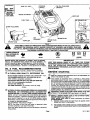
MODEL NO. 143.99670E
6.75 RESERVE POWER
12.56 CUBIC INCH (207cc)
DISPLACEMENT
SOLID STATE IGNITION
ENGIN
CAUTION:
• Operating
Read RULES for
Safe OPERATION
and INSTRUCTIONS
• Maintenance
• Repair Parts
Carefully
A
WARNING:
Califomia Proposition 65
known to the State of California
to cause cancer,
The engine exhaust from this product contains
birth defects or other reproductive
harm.
chemicals
Sold by SEARS, ROEBUCK AND CO., CHICAGO, IL 60684 U.S.A.
and SEARS CANADA, INC., TORONTO, ONTARIO, CANADA
Printedin U.S.A.
2-1-99
181-1183.11
I
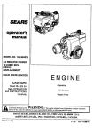
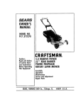
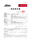
STARTER
HANDLE
OIL FILL PLUG AND
DIPSTICK
MODELAND
D.O.M. DECAL
MUFFLER
OIL DRAIN PLUG
SPARK PLUG WIRE
PRIMER_
OIL DRAIN PLUG
SPARK PLUG
IFFLER
SPARK PLUG
SPARK PLUG
WIRE
/
BOTTOM OF ENGINE
Figure 1
THIS SYMBOL POINTS OUT IMPORTANT SAFETY INSTRUCTIONS WHICH IF NOT FOLLOWED COULD
ENDANGER THE PERSONAL SAFETY AND/OR PROPERTY OF YOURSELF AND OTHERS. READ AND
FOLLOW ALL INSTRUCTIONS IN THIS MANUAL AND ANY PROVIDED WITH THE EQUIPMENT ON WHICH
THIS ENGINE IS USED BEFORE A'I-rEMPTING TO OPERATING.
THESE
SYMBOLS
MAYAPPEARON
THE ENGINE:
(_
4_
FAST
SLOW
STOP
ENGINES WHICH ARE CERTIFIED TO COMPLY WITH CALIFORNIA
.....
AND U.S. EPA EMISSION REGULATIONS FOR ULGE ENGINES: Ar_
certifiedto operate on regularunleaded gasoline. Include the following ':_
emissioncontrolsystem(s): EM, TWC (it so equipped); Do not include
any user adjustablefeatures -'therefore no other adjustmentsare needed:
_'"
OIL & FUEL RECOMMENDATIONS
TO OPERATE
HIGH
QUALITY,
DETERGENT
OIL.
CHOKE
IMPORTANT
:
1=dDF..I;'rJrtl=
li_ =__'_
STARTING
'
(,JJ REA_ALL INSTRUCTIONS PROVIDED WiTH THE EQUIPMENT ON
-; _
OIL SUMP CAPACITY: 27 ounces (1-3/4 U.S. pint,S)
.80 liter
_J
B
FULL
KEEP THiS_,,MANUAL HANDY AT ALL TIMES FOR FUTURE
REFERENCI=_ READrFCAREFULLYAND FAMILIARIZEYOURSELF
Be sure original container is marked: A.P.I. service "SF" - "SJ':,
FOR SUMMER (ABOVE 32°F; (PC) USE SAE 30 OIL.
(SAE 10W30 is acceptable substitute.)
FOR WINTER (BELOW 320F; (PC) USE SAE 5W30 OIL.
(SAE 10W is an acceptable substitute.)
DO NOT USE 10W40 OIL.
I'_
WITH .THE' OPERATING,
MAINTENANCE
AND SAFETY
JNSTRUCTIONS. THIS MANUAL ALSO CONTAINS A COMPLETE
:_ PARTS LISTING:
ENGINE, YOU WILL NEED THE FOLLOWING:
(_) A CLEAN,
J'_
OFF
a4k
A FRESH, CLEAN, UNLEADED
REGULAR,
UNLEADED
PREMIUM,
OR REFORMULATED
AUTOMOTIVE
,_k
GASOLINE
ONLY. DO NOT USE LEADED GASOLINE.
NOTE: DO NOT USE GASOLINE CONTAINING METHANOL
(WOOD ALCOHOL). Gasoline containing up to 10% ethanol or
grain alcohol ('Gasohol'), or up to 15% MTBE (Methyl Tertiary
Butyl Ether), may be used but requires special care when engine
is unused for extended pedods.
See "STORAGE" instructions of Page 4.
NOTE: Use clean oil and fuel and store in approved, clean
covered containers. Use clean fill funnels.
Never use "stale" gasoline left over from last season or stored for
long pedods.
Page 1
WHICH THIS ENGINE IS USED.
THIS ENGINE IS EQUIPPED WITH A FEDERALLY MAN DATED
MECHANISM WHICH STOPS THE ENGINE. DO NOT INTERFERE
WITH OR BYPASS THIS MECHANISM. PARTS OF THE MECHANISM
MAYBE SUBJECTTO WEARANDMUST BECHECKED ONCE A YEAR
BY AN AUTHORIZED SEARS ROEBUCK AND CO. (OR SEARS
CANADA.INC.) SERVICE CENTER. INTHE EVENT THE MECHANISM
FAILS FOR ANY REASON,YOU MUST NOT USETHE ENGINE UNTIL
CORRECTED BY AN AUTHORIZED SEARS ROEBUCKAND CO. (OR
SEARS CANADA, INC.) SERVICE CENTER.
DISCONNECT SPARK PLUG WIRE FROM SPARK PLUG AND
ATrACH IT TO RETAINING POST (see Figure 6 on Page 3).
INSTALL ENGINE BRAKE CABLE AND STARTER ROPE:
BRAKE CABLE (see Figure 2):
Attach engine brake cable to brake mechanism as shown.
STARTER ROPE:
A. Depress mower control bar (see Figure 3) against mower
handle and hold it in this position.
B.
Pullat least2 feet of starterropeout of starter and tie a slip
knotat startertopreventstarterropefrom rewindingback into
starter.
181-1183-11
BEFORE
STARTING
STARTING
(Continued)
C.
Feed starter rope through starter handle (see Figure 5) and
tie a left hand knot, leaving 1/2 inch to 1 inch of starter repeRI
extending beyond left hand knot. DO NOT PULL LEFT HAND
KNOT INTO STARTER HANDLE YET.
O.
With starter handle resting on rope guide (see Figure 4),
check starter rope for slack, If there is any slack, pull more
starter rope through starter handle and relocate left hand
knot to eliminate slack.
NEVER RUN ENGINE INDOORS OR IN ENCLOSED, POORLY
VENTILATED
AREAS.
ENGINE
EXHAUST
CONTAINS
CARBON MONOXIDE, AN ODORLESS AND DEADLY GAS
(CARBON
MONOXIDE
IS ALSO PRESENT
IN ENGINE
EXHAUST FROM LIQUID PETROLEUM (LPG) AND NATURAL
GAS FUEL SYSTEMS).
u
E.
Untie slip knot at starter.
F.
Pull left hand knot into starter handle.
A
_k
KEEP HANDS, FEET, HAIR AND LOOSE CLOTHING AWAY
FROM ANY MOVING PARTS ON ENGINE AND EQUIPMENT.
I
WARNING - TEMPERATURE
OF MUFFLER AND NEARBY
AREAS MAY EXCEED 150°F (65°C). AVOID THESE AREAS.
I
NOTE:
(_
CHECK
OIL LEVEL:
IMPORTANT:
NEVER RUN ENGINE UNLESS OIL LEVEL IS
BETWEEN "FULL" AND "ADD" MARKS ON
DIPSTICK.
,_
I
_
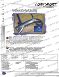
See equipment manufacturer's instructions for control
positions which correspond to engine control positions
in Figure 2.
BRAKE CONTROL
CHECK OIL LEVEL OFTEN DURING ENGINE BREAt(-IN.
NEVER RUN ENGINE UNLESS OIL FILL PLUG IS TIGHTENED
SECURELY INTO OIL FILL HOLE.
A. POSITION EQUIPMENT SO ENGINE IS LEVEL.
B. Clean area around oil fill plug (see Figure 1).
C. Remove oil fill plug and dipstick. /
D. Wipe dipstick clean, insert it into oil fill hole and tighten
securely.
E. Remove oil fill plug and check oil level. If level is not up to
=FULL" mark on dipstick, add recommended oil, until it is.
POUR SLOWLY,
Wipe dipstick clean each time oil level"is checked.
DO NOT FILL ABOVE =FULL" MARK ON DIPSTICK.
F, Replace oil fill plug and tighten securely.
See =MAINTENANCE" section for any future oil level and oil
change instructions (see Page 3).
(_
I
-_ CABLE
_PRIMER
__CAR
BOWL DRAIN
SCREw
BURETOR
CONTROL KNOB IN
'FAST" OR START
POSITION
C)
ENGINE
WITH
Figure2
PRIMER
1) Move control lever (figure 2) to =FAST" or =START" (see
equipmentmanufacturer'sinstructions).
2) The carburetoron yourengine hasbeen completely edjusteq
at the factory. When startinga cold engine,pushred primer
bulbfirmly with your thumb 3 tlmee, allowingprimerbulbto
returncompletely to originalpositionbetween pushes. Repeat the above for each starter operationas necessary.
NOTE: DO NOT USE PRIMER TO RESTART A WARM
ENGINE AFTER A SHORT SHUTDOWN.
3) Operate mower controlto release engine brake.
FILL FU EL TAN K with gasoline as specified in the preceding
"OIL & FUEL RECOMMENDATIONS,"
item 2,
NEVER MIX OIL WITH GASOLINE
Never use =stale" gasolin_ left over from last season or stored for
long periods.
NEVER FILL FUEL TANK INDOORS. NEVER FILL FUEL TANK
WHEN ENGINE IS RUNNING OR HOT. DO NOT SMOKE WHEN
I:ILLINP. RII=LTANK
4)
a) RECOIL STARTERS: Grasp starter handle (figure 3) and
pull rope out slowly until you feel drag. Let rope rewind
slowly. Pull rope with rapid, full arm stroke. Return robe
slowly to original position.
NOTE: If engine fails to start after three pulls, repeat steps
2-3 above.
b) ELECTRIC STARTERS: Crank engine.
NOTE:
If engine does not start after five seconds of
cranking, stop and repeat steps 2-3 above.
NOTE:
If equipped with a snap-in control as shown, no
adjustment is required.
NEVER FILL FUEL TANK COMPLETELY. FILL TANK TO 1/2"
BELOW BOTFOM OF FILLER NECK TO PROVIDE SPACE FOR
FUEL EXPANSION.WIPE ANY FUEL SPILLAGE FROM ENGINE
AND EQUIPMENT BEFORE STARTING ENGINE.
_bANY
LIQUEFIED PETROLEUM (LPG) OR NATURAL GAS FUEL
SYSTEM MUST BE LEAKPROOF AND M EETALLAPPLICABLE
I CODES AND REGULATIONS.
CHECK THE FOLLOWING:
A.
,_
B.
BE SURE
EQUIPMENT
IS IN NEUTRAL
STOPPING
GEAR WITH
CLUTCHES, BELTS, CHAINS AND SAFETY SWITCHES
DISENGAGED.
(FOLLOW
EQUIPMENT
MANUFACTURER'S INSTRUCTIONS.) THIS SHOULD PLACE
ANY SAFETY SWITCHES IN SAFE STARTING PosmoN.
Be sure spark plug wire is attached to spark plug (see Figure
1).
(_See
mower manufacturer's
(_) AFTER
ENGINE
instructions.
IS STOPPED:
_ILA.
DISCONNECT
AND
A'n'ACH
,_B.
NEVER STORE ENGINE WITH FUEL IN TANK IN DOORS I
OR IN ENCLOSED,
POORLY VENTILATED
AREAS, J
WHERE FUEL FUMES MAY REACH AN OPEN FLAME, I
SPARK OR PILOT LIGHT AS ON A FURNACE, WATER
HEATER, CLOTHES DRYER OR OTHER GAS APPUANCE.
Page 2
SPARK
PLUG
FROM
SPARK
IT TO RETA
N WIRE
NG POST
(see
Raure PLUG
61.
181-1183-11
MAINTENANCE
STARTER
HANDLE
CONTROL
SAR
ROPEGUIDE
FOAM FILTER:
_
MOWER
HANDLE
MOWER
(Continued)
Clean and re-oileverythree (3) monthsor every25 operating
hours. Clean and re-oil daily if used in extremely dusty
conditions.
ulOWER _
A. Wash in water and detergent solution and squeeze (don't
twist until all did is removed.)
STARTER ROPE
NO SL_
_RMI,_SI_._E
B. Rinse thoroughly in clear water.
Figure 4
Figure 3
C. Wrap in a clean cloth and squeeze (don't twist) to distribute
oil and remove excess oil.
B. TO REMOVE AND INSTALL FILTER:
1. Remove cover from body by loosening wing nut.
Swing cover down to remove from hinge.
1/2 TO 1 INCH
SPARK PLUG WIRE
RETAINING
Figure 5
2. Inspect filter for discoloration or dirt accumulation. If either
is present, service per preceding "TO SERVICE FILTER"
instructions.
SPAF_K_LUG
POST
Figure 6
!
3. Clean inside of cover and body thoroughly.
4. Re-install filter in body.
MAINTENANCE
(_
CHECK
5. Install cover on body by aligning hinges between body and
cover. Swing cover upward against body. Tighten wing nut
securely.
t
_RARNING
- TEMPERATURE
OF MUFFLER AND NEARBY
EAS MAY EXCEED 150aF (650C)./).VOID THESE AREAS.
J
OIL LEVEL:
JT
Checkoillevel everyfive(5) operatinghoursor eachtimeengine
is used.See "3CHECK OIL LEVEL"in=BEFORESTARTING"on
Page 2.
FILTER
(_ CHANGE
OIL:
Change oil after first two (2) operating hours and every 25
operating hours thereafter, more often if operated in extremely
OVER
dusty or dirty conditions. Change oil while engine is still warm
from recent runnino.
_kA.
B
C.
DISCONNECT
PLUG WIRE
FROM
SPARK
AND
ATTACH SPARK
IT "_ORETAINING
POST
(sea
Figure PLUG
6).
Position equipment so engine oil drain plug is lowest point
on engine.
Remove oil drain plug and oil fillplug to drain oil (see Figure
BODY
Figure7
(_
1).
D.
E.
Replace oil drain plug and tighten securely.
Fill oil sump with recommended oil. See =OIL & FUEL
RECOMMENDATIONS _and "CHECK OIL LEVEL" on Page
1.
F. Replace oil fill plug and tighten securely.
G. Connect spark plug wire to spark plug.
H. Wipe up any spilled oil and/or gasoline.
NOTE: If it is difficult to reach the oil drain plug, drain fuel.
Remove oil fill plug and tip mower on its side. Drain oil
into a suitable container.
(_) AIR CLEANER
(see Figure 7):
_,NEVER
RUN ENGINE WITHOUT COMPLETE
STALLED ON ENGINE.
A. TO SERVICE FILTER:
AIR CLEANER
SPARK
PLUG (see Figure8):
Thissparkignitionsystemmeatsall requirementsoftheCanadian
Interference-Causing Equipment Regulations. This engine
complieswithall currentAustralianand New Zealand limitations
regardingelectromagneticinterference.Checksparkplugyearly
or every 100 operatinghours.
A.
Clean area aroundspark plug.
B.
Remove and inspectspark plug.
C.
Replace spark plug if electrodes are pitted, burned or
porcelain is cracked. For replacement use Champion RJ19LM or equivalent.
NOTE: A resistor spark plug must be used for replacement.
O.
Check electrodes gap with wire feeler gauge and set gap at
.030 if necessary.
E.
Install spark plug, tighten securely.
PAPER FILTER:
DO NOT ATI'EMPT TO CLEAN OR OIL FILTER.
Replacefilter once a year or every 100 operatinghours,more
often if used in extremelydusty or dirtyconditions.
Replacementfiltersare availableat any Sears Roebuckand
Co. (or Sears Canada, Inc.) Service Center,
Page 3
Figure 8
181-1183-11
MAINTENANCE
(_) COOLING
SYSTEM
MAINTENANCE
(Continued)
NOTE:
Fuel stabilizer (such as STA-BIL) is an acceptable
alternative in minimizing the formation of fuel gum deposits
during storage. Add stabilizer to gasoline in fuel tank or
storage container. Always follow mix ratiofound on stabilizer
container. Run engine at least 10 minutes after adding
stabilizer to allow it to reach carburetor.
(see Figure 9):
IMPORTANT: Frequently remove any gross clippings, dirt and
debris from cooling fins, air intake screen and levers and linkage
(see Figure 1), This will help ensure adequate cooling and
correct engine speed.
(_) DRAIN
I
COOLING FINS
CARBURETOR:
Drain carburetor by removing bowl drain screw (sea Figure
1N'l whiP.h i_ Inr.,_t_d h_lnw r_rhHrAtnr
DRAIN FUEL INTO APPROVED CONTAINER OUTDOORS,
AWAY FROM OPEN FLAME. BE SURE ENGINE IS COOL.
DO NOT SMOKE.
_k
AIR INTAKE
SCREEN
(Continued)
LEVERS AND
LINKAGE
Figure 9
,SCREW
_kBOLTS
AND ATTACHMENTS, AND KEEP THESE n"EMS I
(_
CHECKENGINEANDEQUIPMENTOFTENFORLOOSENUTS,
'_IGHTENED.
BOWL DRAIN
CARBURETOR
CARSU RETOR-_-
ADJUSTMENTS
DO NOT MAKE UNNECESSARY
ADJUSTMENTS.
FACTORY
S ETTINGS ARE SATISFACTORY FOR MOST APPLICATIONS AND
CONDITIONS.
IF ADJUSTMENTS ARE NEEDED, PROCEED AS
FOLLOWS:
Figure 10
_)CHANGE
Change oil if it has not been changed in the last three (3) months.
See "CHANGE OIL" instructions in =MAINTENANCE" section on
(_CARBURETOR
If you think your carburetor needs adjusting, sea your nearest
SEARS, ROEBUCK AND CO. (OR SEARS CANADA, INC.)
SERVICE CENTER. Engine performance should not be affected
at altitudes up to 7,000 feet. For operation at higher elevations,
contact your nearest SEARS, ROEBUCK AND CO. (OR SEARS
CANADA, INC.) SERVICE CENTER.
(_
ENGINE
Page 3.
(_OIL
SPEED
_INEVER
TAMPER WlTM ENGINE GOVERNOR
WHICH IS
ACTORY
SET
FOR
PROPER
ENGINE
SPEED.
OVERSPEEDING ENGINE ABOVE FACTORY HIGH SPEED
SETTING CAN BE DANGEROUS.
CHANGING OF ENGINE-GOVERNED
SPEED WILL VOID
ENGINE WARRANTY.
A.
B.
BORE:
Removesparkplugand pourone (1) ounce(30 ml)ofengine
oil into spark plug hole.
B.
Cover spark plug hole with a rag.
C.
Crank engine over, slowly,several times.
CRANKING
ENGINE
OVER
SLOWLY.
AVOID SPRAY
FROM
SPARK
PLUG HOLE WHEN
D.
Replace spark plug.
(_) CLEAN
ENGINE:
Remove any clippings,dirt,or chafffrom extedorof engine.
INDOORS
SEVERNCLOSED,
STORE
ENGINE
WITH
FUEL
IN
TANK
IN
POORLY VENTILATED AREAS, WHERE OR
FUEL
FUMES MAY REACH AN OPEN FLAME, SPARK OR PILOT
LIGHT AS ON A FURNACE, WATER HEATER, CLOTHES
DRYER OR OTHER GAS APPLIANCE.
(_) DRAIN
CYLINDER
A.
_k
STORAGE
IF ENGINE IS TO BE UNUSED
PREPARE AS FOLLOWS:
OIL:
FOR 30 DAYS OR MORE,
FUEL SYSTEM:
Remove all gasoline from carburetor and fuel tank to prevent
gum deposits from forming on these pads and causing
possible malfunction of engine.
AWAY FROM OPEN FLAME. BE SURE ENGINE IS COOL
DRAIN
INTO APPROVED CONTAINER OUTDOORS,
DO NOTFUEL
SMOKE.
Run engine until fuel tank is empty and engine stops due to
lack of fuel.
NOTE:
If "Gosohol" has been used, complete above
instructions and then put 1/2 pint of gasoline into fuel tank
and repeat above instructions.
(_
BATTERY
(if so equipped):
See equipment manufacturer's
battery.
instructions for proper storage of
GENERAL
Just as your automobile needs professional mechanical maintenance
from time to time, so does your Craftsman engine. Replacement of the
spark plug and air cleaner is made necessary by NORMAL use.
Professional Air-Cooled Engine Service is as close as your nearest
Sears Roebuck and Co. (or Sears Canada, Inc.) Service Center.
A yeady check-up or tune-up by Sears is a good idea to avoid
breakdowns or delay.., do itat the end ofthe season, then you're ready
for the next. We even prepare it for storage for you.
Page 4
181-1183-11
I
TROUBLESHOOTING
THE FOLLOWING
MAY HELP AVOID A DELAY IN YOUR
SAVE THE EXPENSE OF A SERVICE CALL.
WORK OR
;NGINE FAILS TO START OR STARTS WITH DIFFICULTY
CAUSE
REMEDY
Controlsnot in start position.
Move ENGINE CONTROL or equipmentcontrolto 'HI" or
START postion. See "STARTING" instructionsin this
manual.
Spark plug wire disconnectedfromspark plug,
Connect SPARKPLUG
Spark plugfouled.
Remove SPARK PLUG and clean it. See "SPARK
PLUG" instructions in "MAINTENANCE" section in this
manual.
Spark plugporcelaincracked.
Installnew spark plug.
Insufficientfuel.
Fill FUELTANK per 'BEFORE STARTING' instructions.
Water or dirt in fuel.
Drain FUEL TANK and re-fillwith clean,fresh gasoline.
See "BEFORE STARTING"instructionsin this manual.
Impropercarburetoradjustment
Adjustcarburetor(if applicable). See "ADJUSTMENTS"
sectionin this manual.
WlREtoSPARKPLUG.
ENGINE LACKS POWER
REMEDY
CAUSE
Dirtyair cleaner.
Replace or clean air cleaner per "AIR CLEANER"
instructions in 'MAINTENANCE" section in this manual.
Impropercarburetoradjustment.
Adjustcarburetor (if applicable). See "ADJUSTMENTS"
sectionin thismanual.
Lackof lubricaiton.
Filloil sumpto proper level. See "BEFORE STARTING"
instructionssectionin this manual.
ENGINE MISSES UNDER LOAD
REMEDY
CAUSE
Spark plug fouled.
Remove SPARK PLUG and clean it. See "SPARK
PLUG" instructions in "MAINTENANCE" section in this
manual.
Spark plug porcelain cracked.
In_allnew SPARK PLUG.
Improperspark pluggap.
Regap SPARK PLUG electrodes. See 'SPARK PLUG"
instructions in "MAINTENANCE" section in this manual.
Impropercarburetor adjustment
Adjustcarburetor(if applicable). See "ADJUSTMENTS"
sectionin this manual.
Page 5
181-1183-11
SEARS,
ROEBUCK
AND CO.
Federal and California Emission Control Systems Limited Warranty
Utility and Lawn and Garden Engines
CALIFORNIA
& US EPA EMISSION CONTROL
WARRANTY STATEMENT
The U. S. Environmental Protection Agency ('EPA*), the California Air
Resources Board ('CARB") and Sears, Roebuck and Co. are pleased to explain
the Federal and California Emission Control Systems Warranty on your new
utility or lawn and garden equipment engine. In California, new 1995 and later
utility and lawn and garden equipment engines must be designed, built and
equipped to meet the State's stringent anti-smo_ standards. In other states, new
1997 and later model year engines must be designed, built and equipped, at the
time of sale, to meet the U.S. EPA regulations for small non-read engines.
Sears, Roebuck and Co. will warrant the emission control system on your utility
or lawn and garden equipment engine for the periods of time listed below,
provided there has been no abuse, neglect, unappreved modification, or
improper maintenance of your utility or lawn and garden equipment engine.
B. GENERAL EMISSIONS WARRANTY COVERAGE:
Sears, Roebuck and Co.
warrants to the original, end-use purchaser of the new engline or equipment and
to each subsequent purchaser that each of its utility and |awn and garden
equipment engines is:
1. Designed, built and equipped so as to conform with all applicable
regulations adopted by the Air Resources Board pursuant to its authority
in Chapters 1 and 2, Part 5, Division 26 of the Health and Safety Code,
and
2.
C.
Your emission control system may include parts such as the carburetor, ignition
system and exhaust system. Also included may be the compression release
system and other emission-related assemblies.
°
MANUFACTURER'S EMISSION CONTROL SYSTEM
WARRANTYCOVERAGE
RESPONSIBILITIES
Any warranted, emisslans-rblated part which is scheduled for replacement
as required maintenance in the Owner's Manual, shall be warranted for the
period of time prior to the first scheduled replacement point for that pert.
If the part fails prior to the first scheduled replacement the pert shall be
repaired or replaced by Sears, Roebuck and Co. according to Subsection
4 below. Any such emissions-related part repaired or replaced under tbe
ECS Warranty, shall be warranted for the remainder of the ECS Warranty
Period prior to the first scheduled replacement point for such emissionsrelated part.
AS the utility or lawn and garden equipment engine owner you are responsible
for the performance of the required maintenance listed in your Owner's Manual,
but Sears, Roebuck and Co. will not deny warranty solely due to the lack of
receipts or for your failure 1o provide written evidence of the performance of all
scheduled maintenance.
As the utility or lawn and garden equipment engine owner, you should however
be aware that Sears, Roebuck and Co. may deny you warran nty coverage ff your
utility or lawn and garden equipment or a part thereof has lailad due to abuse,
neglect, improper maintenance or unapproved
modifications.
4. Repair or replacement of any warranted, emissions-related part under this
ECS Warranty shall be performed at no charge to the owner at a Sears
Roebuck and Co. Authorized Service Outlet.
You are responsible for presenting your utility or lawn and garden equipment
engine to a Sears, Roebuck and Co. Authorized Service Outlet as soon as a
problem exists. The warranty repairs should be completed in a reasonable
amount of time, not to exceed 30 days.
5. The owner shall not be charged for diagnostic labor which leads to the
determination that a part covered by the ECS Warranty is in fact
detective, provided that such diagnostic work is performed at a Sears,
Roebuck and CO. Authorized Service Outlet.
Warranty service can be arranged by contacting either a Sears Roebuck and
Co. Authorized
Service Outlet, or 'by contacting Sears, Roebuck and Co. at 1800-473-7247.
6. Sears, Roebuckand Co. shall be liable for damages to other original
engine componentsor approvedmodificationsproximatelycaused boy a
failure under warranty of an emission-relateqpart covered by the ECS
Warranty.
IMPORTANTNOTE
This warranty statement explains your rights and obligations under the Emission
Control System Warranty ('ECS Warranty") which is provided to you by Sears,
Roebuck and Co. pursuant to California law..See
also the Sears, Roebuck and
Co. Limited Warranties for Sears, Roebuck and Co. which is enclosed therewith
on a separate sheet and also is provided to you by Sears Roebuck and Co.
The ECS Warranty applies only to the emission control system of your new
engine. To the extent that there is an conflict in terms between the ECS
Warranty and the Seam, Roebuck and/Co. Warranty the ECS Warranty shall
app y except n any circumstances in which the Sears, Roebuck and Co.
Warranty may provide a longer warranty period. Both the ECS Warran_ and
the Sears, Roebuck and Co. Warranty describe important rights and obhgations
with respect to your new engine.
7. Throughout the ECS Warranty Period Sears Roebuck and Co. shall
manta n a supp y of warranted emission-rblated parts sufficient to meet
the expected demand for such emission-related parts.
Any Seam, Roebuck and Co. authorized and approved emission-related
replacement part may be used in the performance of any ECS Warranty
maintenance or repair and will be provided without charge to the owner.
Such use shall not reduce Sears, Roebuck and Co. ECS Warranty
obligations.
Unapproved odd-on or modified parts may not be used to modify or
repair a Sears, Roebuck and Co. engine. Such use voids this ECS
Warranty and shall be sufficient grounds for disallowing an ECS Warranty
claim. Sears, Roebuck and Co. shall not be liable hereunder for failures
of any warranted parts of a Sears, Roebuck and Co. engine caused by
the use of such an unapproved add-on or modified part.
Warranty service can only be performed by a Sears, Roebuck and Co.
Authorized Service Outlet. At the time of requesting warranty service, evidence
must be presented of the date of sale to the original purchaser. The purchaser
shall pay any charges for making service calls and/or for transporting the
products to and from the place where the inspection and/or warranty work is
performed. The purchaser shall be responsible for any damage or loss incurred
in connection with the trans
rtation of any engine or any pert(s) thereof
submitted for inspection an_)°or warranty work.
EMISSION-RELATED
If you have any questions regarding your warran
rights and responsibilities
you should contact Sears, Roebuck and Co. at 1=-h_-473-7247.
EMISSION
CONTROL SYSTEM
parts on your engine,
Any warranted, emissions-related
part which is scheduled only for regular
inspection as specified in the Owner's Manual shall be warranted for the
ECS Warranty Period. A statement in such written instructions to the
effect of "repair or replace as necessary _, shall not reduce the ECS
Warranty Period. Any such part repaired or replaced under the ECS
Warranty shall be warranted for the remainder of the ECS Warranty
Pedod.
Emission control systems on 1995 and later model year California utility and
lawn and garden equipment engines are warranted for two years as hereinafter
noted. In other states, 1997 and later model year engines are also warranted for
two years. If, during such warranty period, any emissLon-related part on your
engine is defective in materials or workmanship, the part will be repaired or
replaced by Sears, Roebuck and CO.
WARRANTY
The ECS Warranty only pertains to emissions-relafod
as follows:
Any warranted, emissions-related parts which are not scheduled for
replacement as req_uired maintenance in the Owner's Manual shall be
warranted for the ECS Warranty Period. If any such part fails dedng the
ECS Warranty Period, it shall be repaired or replaced by Sears, Roebuck
and Co. according to Subsection 4 below. Any such bert repaired or
replaced under the ECS Warranty shall be warranted for any remainder of
the ECS Warranty Period.
Where a warrantable condition exists, Sears, Roebuck and Co. will repair your
utility or lawn and garden equipment engine at no cost to you for diagnosis, parts
and labor,
f
OWNER'S
Free from defects in materials and workmanship which, at any time
during the ECS Warranty Period, will cause a warranted emissmns-relatad
part to fail to be identical in all material respects 1o the part as described
in the engine manufacturer's
application for certification.
WARRANTY
Emission Control System Warranty
"ECS Warranty') for 1995 and later model
year California utility and lawn andgarden equipment engines (for other states,
1997 and later model year engines):
A. APPLICABILITY:
This warranty shall apply to 1995 and lat6r model year
California utility and lawn and garden equipment engines (for other states, 1997
and later model year engines). The ECS Warranty Period shall begin on the date
the new engine or equipment is delivered to its original end-use pomhaser
and
shall con inue for 24 consecutive months thereafter.
PARTS INCLUDE
THE FOLLOWING:
1. Carburetor Assembly and its Internal Components
a) Fuel filter
b) Carburetor gaskets
c) Intake pipe
2. Air Cleaner Assembly
a) Air filter element
3. ignition System, including:
a) Spark plug
b) Ignition module
c) Flywheel assembly
4. Catalytic Muffler (if so equipped)
a) Muffler gasket (g so equipped)
b) Exhaust manifold (it so equipped)
5. Crankcase Breather Assembly and its Ccmponents
a) Breat her connection tube
7.22.9"/I_A/_ARB
Sears, Roebuck
and Co., Hoffman
Page 6
Estates, IL 60179
U.S.A.
18:1-1183-11
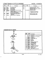
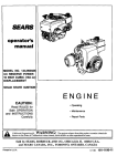
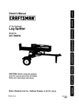
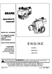
CRAFTSMAN
301
4-CYCLE ENGINE
MODEL:143.996706
3OO
110
370A
292 _'e
371R
/
292
262
204:
256 •
41
416
lg_.
12
45
187A
24O
45
4O
_77
350
239
380
83_
,243B
\
42
251
75
Page 7
181-1183-11
CRAFTSMAN
Ref.
No.
Part
No.
1
2
6
9
10
11
12
12C
14
15
16
17
18
19
20
25
36177
27652
36059
590568
36002
36003A
32447
"36005A
28277
36006
36008
31335
651018
36103
36010
36186
26
30
40
40
41
41
650802
36185
40004
40005
36070
36071
42
42
43
45
46
48
5O
52
69
70
72
72A
73
75
8O
81
82
83
85
86
89
90
91
92
93
100
101
103
110
119
120
125
125
126
126
130
135
15O
151
151A
40006
40007
20381
36023A
32610A
36030
36031A
29914
"36032A
37271
30572
28483
28833
36010
30574A
30590A
30591
36057
36034
650924
611154
611155
611156
650815
650816
34443B
610118
651007
36054
*36061
36187
36471
36472
29314C
29315C
6021A
35395
31672
31673
40016A
4-CYCLE ENGINE
MODEL:143.996706
Ref.
No.
Part Name
Cylinder (Incl. 2,10,12, 20 & 125)
Dowel Pin
Breather Element
Screw, 10-24 x 3/4"
Breather Valve Body
Check Valve
Breather Tube
Breather Cover & Gasket
Flat Washer
Governor Rod (Machined)
Govemor Lever
,,
Governor Lever Clamp
Screw, Torx T-15, 8-32 x 19/64"
Govemor Spring
Oil Seal
P
Blower Housing Baffle Ass'y. (Incl.
195)
Screw, 1/4-20 x 5/8"
Crankshaft
Piston,Pin,Rihg Set (Std.)
Piston,Pin,Ring Set (.010 OS)
Piston & Pin Ass'y.(Std.) (Incl. 43)
Piston & Pin Ass'y.(.010 OS)
(Inc1.43)
Ring Set (Std.)
Ring Set (.010 OS)
Piston Pin Retaining Ring
Connecting Rod Ass'y. (Incl. 46)
Connecting Rod Bolt
Valve Lifter
Camshaft (MCR)
Oil Pump Ass'y.
Mounting Flange Gasket
,
Mounting Flange (Incl. 72 thru 85)
Oil Drain Plug (Incl. 73)
Oil Drain Plug
Drain Plug Gasket
Oil Seal
Governor Shaft
Washer
Governor Gear Ass'y. (Incl.81)
Governor Spool
Idler Gear
169
172
174
177
184
186
187A
190
191A
192
193
194
195
198
199
202
203
204
205
215
239
240
243B
245
250
251
251A
255
256
260
262
263A
275
276
277
285
287
290
292
300
301
305
307
Screw, 1/4-20 x 1-9/16"
Flywheel Key
Flywheel
Flywheel Fan
Belleville Washer
Flywheel Nut
Solid State Ignition
Spark Plug Cover
Screw, Torx T-15, 10-24 x 15/16"
Ground Wire
Cylinder Head Gasket
Cylinder Head
Exhaust Valve (Std.) (Incl. 151)
Exhaust Valve (1/32" OS)
Intake Valve (Std.) (Incl. 151)
Intake Valve (1/32" OS)
Screw, 5/16-18 x 1-1/2"
Resistor Spark Plug .(RJ19LM)
Valve Spring
Lower Valve Spring Cap
Intake Valve Seal
308
310
346A
347
350
Part
No,
"27234A
32755
30200
650925A
36183
36OO9
36195
36013
36012
36016
36015
36014
610973
36017
36018
36482
31342
651029
651030
36051
*36048
36190
651041
36046
36191
650928
650933
36193
650983
36188
650737
36192
36107A
36043
650927
34449A
650926
29774
26460
36189
36246
I 36063
35499
36040
36064
28763
650898A
36045A
Part Name
Valve SpringBox Gasket
Valve SpringBox Cover
Screw, 10-24 x 9/16"
CarburetorMountingStud
CarburetorGasket
GovernorLink
Air Baffle
Brake LeverAss'y.
Brake ControlLever
Brake ControlLever Link
Brake Spring
RetainingRing
TerminalAss'y.
Brake ControlLever Spring
Brake Lever Bushing
CompressionSpring
CompressionSpring
Screw,Torx1-10, 5-40 x 7116"
Screw,TorxT-IO, 6-32 x 17/32"
ControlKnob
CarburetorTo Air Cleaner Gasket
Air Cleaner Body(Incl. 239 & 350)
Air Cleaner Stud
Air Cleaner Filter
Air Cleaner Cover
Lock Nut, 1/4-20
Wing Nut, 1/4-20
ControlPlate
Screw, 8-32 x 21/64"
Blower Housing
Screw, 1/4-20 x 1/2"
Starter Grill
Muffler
LookingPlate
Screw, 5/16-18 x 2-11/32"
Starter Cup
Screw, 8-32 x 21/64'
Fuel Line
Fuel LineClamp
Fuel Tank (Incl.301)
Fuel Cap
Oil Fill Tube
"O" Ring
Fill Tube Clip
Dipstick
Screw, 10-32x 35/64"
Scraw, 10-32x 27/32"
Primer
*IndicatesParts Included in
Gasket Set, Rel. No. 400.
I
Page 8
181-1183-11
CRAFTSMAN
Ref.
No.
370A
370B
370C
370R
380
390
4-CYCLE ENGINE
Part
No.
36261
36155
37318
37317
640020A
590739
400
416
36062D
36085
417
650821
CARBURETOR
MODEL:143.996706
Ref.
No.
Part Name
Lubdcation Decal
Control Decal
Primer Decal
Warning Decal
Carburetor (Incl. 184,187A & 239)
Rewind Starter
(NOTE: This engine could have been
built with 590702 starter).
Gasket Set (Incl. Items Marked *)
Spark Arrestor Kit (Incl. 417)
(Optional)
Screw, 10-32 x 1/2" (Optional)'
Part
No.
Part Name
181-1183-11
Replacement Engine 760819C,
order from 71-999
Replacement Short Block 750797C,
order from 71-999
Operators Manual
900
900
*Indicates Parts Included in
Gasket Set, Ref. No. 400.
RPM High 2900 to 3200
RPM Low 2450 to 2750
NO. 640020A
Ref.
No.
Part
No.
640020A
I
1
5
6
7
14A
25
27
28
632539
632593
632541
650506
632773
632675A
632544
632543
_(9
632548
632709
632672
632673
640O22
632547
632547
632545
632545
632549
640021
632554
32
33
36
37
37A
38
38A
39
40
47
Page 9
Part Name
Carburetor (Incl. 187B & 239 of Engine
Parts List)
Throttle Shaft & Lever Assembly
Dust Seal
Throttle Shutter
Throttle Shutter Screw
Venturi
Float Bowl
Float Shaft
Float
Float Bowl to Body Gasket
Inlet Needle & Seat
Bowl Drain Screw
Bowl Drain Washer
Main Nozzle Tube
=O" Ring
"O" Ring, Main Nozzle Tube
Spring, Main Nozzle Tube
Spring
Float Bowl Retainer
Main Fuel Jet
Welch Plug, Idle Mix!ng Well
181-1183-11
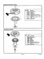
REWIND STARTER NO. 590739
--14
Rid'.
No.
12
13
STARTER
Part
No.
3
6
7
8
11
590739
590740
590616
590617
i590618A
590638
12
590535
13
14
590701
590760
Ref.
No.
Part
NO.
Part Name
Rewind Starter
Retainer
Starter Dog
Dog Spring
Pulley & Rewind Spdng Ass'y
Starter Housing Ass'y (40 degree
grommet)
Starter Rope (Length 98" x 9/64"
dia.)
Starter Handle
Spring Clip
NO. 590702
1
Part Name
13
1
2
3
4
5
6
7
8
11
12
13
B
590702
Recoil Starter
56O599A Spdng Pin (Incl. 4)
59O6O0
Washer
590696
Retainer
590601
Washer
590697
Brake Spdng
590698
Starter Dog
590699
i Dog Spring
590700
Pulley & Rewind Spdng Ass'y,
590703
Starter Housing Ass'y. (40 degree
grommet)
590535
Starter Rope ( 98" x 9/64" dia,)
590701
Starter Handle
5
Page 10
181-1183-11
How to ORDER
SEARS
operator's
manual
Repair Parts
The Model Number can be found on a decal on the blower housing
(See Figure 1). Always mention the Model Number when
requesting service or repair parts for your Craftsman Engine.
All parts listed herein may be ordered from any SEARS,
ROEBUCK AND CO. or SEARS CANADA, INC. retail or catalog
store. If the parts you need are not stocked locally, your order will
be electronically transmitted to a Sears Repair Parts Distribution
Center for expedited handling.
WHEN ORDERING REPAIR PARTS, ALWAYS GIVE THE
FOLLOWING INFORMATION AS SHOWN IN THIS LIST.
1.
The PART NUMBER
2.
The PART DESCRIPTION
3.
The MODELNUMBER
4.
The NAME OF ITEM - ENGINE
MODEL NO. 143.99670q
6.75 RESERVE POWER
12.56 CUBIC INCH (207cc]
DISPLACEMENT
SOLID
STATE IGNITION
CAUTION:
Read RULES for
Safe OPERATION
and INSTRUCTIONS
"YourSears merchandisehas added value when you considerthat Sears has
service units nationwidestaffed with Sears trained technicians..,professional
techniciansspecificallytrained on Sears products,havingthe parts,tools and
equipmentto insurethatwe meet our pledgeto you ... we servicewhatwe sell."
Carefully
Sold by SEARS, ROEBUCK AND CO., CHICAGO,
IL 60684 U.S.A.
and SEARS CANADA, INC., TORONTO, ONTARIO, CANADA
181-1183-11