1
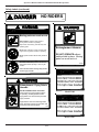
OPERATOR'S MANUAL
MILLCREEK MODELS:
3100/3200 TURF TIGER® SPREADERS
I-86219
PUBLICATION DATE: 1/13/09, Rev. 3
MILLCREEK PART # 43827
Millcreek Manufacturing Company
34 Zimmerman Road
Leola, PA 17540
Phone: 1-800-311-1323 / Fax: 717-656-0952
www.millcreekmfg.com
WARNING: DO NOT assemble, operate, or maintain this equipment without first
reading and understanding the information provided in this manual and the
ADMA Safety Manual for Agricultural Implement Drivelines. Failure to follow
all safety precautions as stated in these manuals may result in serious personal injury
or death.
WARRANTY INFORMATION
Millcreek Manufacturing Company (hereinafter called the Company) warrants to the original Purchaser, the
Equipment, manufactured by the Company, to be free from defects in material and workmanship under normal
use and service. The Company warrants the construction of the equipment sold herein and will replace at the
Company's expense for a period of two years from the date of delivery to the original Purchaser, any parts which
prove defective as determined under the terms of this Limited Warranty. The Company obligation under this
Warranty shall be limited to replacement or repair of any parts thereof, free of charge, to the original Purchaser,
provided, however, that the part(s) to be replaced or repaired, shall, within two years after delivery to the original
Purchaser, be demonstrated to be defective; which determination shall be made by the Company. The said
components or parts must be returned through the Selling Dealer or Distributor directly to the Company with all
transportation charges prepaid. Notice of defect shall be furnished in writing to the Seller and to the agent through
whom the machinery was purchased, disclosing in full all known defects and failure in operation and use.
Reasonable time shall be given to the Seller to remedy any such defects and failures.
Likewise, a ten (10) year, pro-rated warranty is provided on the spray-on polyurethane lining (applied to internal
sides of unit, excluding exterior non-lined surfaces). The high density, polyethelene floorboards are warranted for the
lifetime of the machine from cracking, rotting, splitting, or peeling.
This Warranty does not cover, under any circumstances, any parts, components, or materials which, in the opinion
of the Seller and the Company, have been subjected to neglect, misuse, alteration, accident, or repaired with parts
other than those manufactured by and obtained from Millcreek Manufacturing Company.
This Warranty does not cover components which are already covered by a separate warranty provided by the
supplier of said parts or components.
This Warranty is made in lieu of all other warranties, expressed or implied, including any warranty of
merchantability and fitness for use and purpose and of all other obligations or liabilities on the Company
part and any implied warranty. The Company neither assumes nor authorizes any other person to assume
for it, any other liability in connection with the sale of this equipment. This Warranty shall not apply to
this equipment or to any part thereof which has been subjected to accident, negligence, alteration, abuse,
or misuse.
The Company makes no warranty whatsoever in respect to accessories or parts not supplied by the Company.
The term "original Purchaser," as used in this Warranty, shall be deemed to mean that person for whom the
equipment is originally supplied. This Warranty shall apply only within the boundaries of the continental United
States.
Under this Warranty, the Company cannot guarantee that conditions existing beyond its control will not affect the
Company's ability to obtain materials or manufacture necessary replacement parts.
The Company reserves the right to make design changes, or changes in specifications at any time, without any
contingent obligation on the part of the Company to purchasers of machines and parts previously sold.
TRADEMARKS
The Millcreek logo is a trademark of the Millcreek Manufacturing Company. All other brand or product names
mentioned are the registered trademarks or trademarks of their respective owners.
COPYRIGHT
Copyright © 2009 Millcreek Manufacturing Company. All rights reserved. No part of this publication may be
reproduced, or distributed without the prior written permission of Millcreek Manufacturing Company, 34 Zimmerman
Road, Leola, PA 17540. Subject to change without notice.
TABLE OF CONTENTS
SECTION 1: INTRODUCTION ................................................................................... 1-1
Guide to this Manual .......................................................................................................... 1-1
For Your Safety... .............................................................................................................. 1-1
Safety Labels .............................................................................................................. 1-2
Inspection and Warranty Registration .................................................................................. 1-5
Warranty Registration .................................................................................................. 1-5
SECTION 2: ATTACHING THE SPREADER TO THE TRACTOR ............................ 2-1
Connecting the Spreader Hitch to the Tractor Drawbar ...................................................... 2-1
Attaching the Spreader to the Tractor PTO ......................................................................... 2-2
SECTION 3: OPERATION & ADJUSTMENT ............................................................ 3-1
Understanding TURF TIGER® Spreader Operation ............................................................ 3-1
TURF TIGER Spreader Operating Components .......................................................... 3-1
Guidelines for Loading the TURF TIGER Spreader ...................................................... 3-1
Operating the TURF TIGER Spreader ............................................................................... 3-1
Adjusting the TURF TIGER Spreader ................................................................................ 3-2
Adjusting Tractor Ground Speed ................................................................................. 3-2
Adjusting the Metering Endgate ................................................................................... 3-2
Recommended Settings for TURF TIGER Spreader Operation ........................................... 3-3
Material Weights (Range Per Cubic Yard) ................................................................... 3-3
Material Volume Estimation ......................................................................................... 3-3
Initial Adjustments (Sample Settings) ............................................................................ 3-4
SECTION 4: MAINTENANCE & ADJUSTMENT ....................................................... 4-1
Guidelines for Regular Maintenance .................................................................................... 4-1
General Maintenance ................................................................................................... 4-1
Wheel/Tire Maintenance .............................................................................................. 4-1
Wheel Bearing Maintenance ........................................................................................ 4-2
Procedures for Spreader Adjustment .................................................................................. 4-2
Checking and Adjusting the Floor Apron Chain ............................................................ 4-2
Checking and Adjusting the Apron Drive Chains .......................................................... 4-3
TABLE OF CONTENTS
APPENDIX A: PARTS REFERENCE .........................................................................A-1
General TURF TIGER® Spreader Specifications ................................................................ A-1
Component Parts Ordering Information ............................................................................. A-2
TURF TIGER Spreader Box and Hitch Assembly ............................................................. A-2
TURF TIGER Spreader Wheel/Hub Assembly .................................................................. A-4
TURF TIGER Rear Drive Assembly .................................................................................. A-6
TURF TIGER Front Drive Assembly ................................................................................. A-8
TURF TIGER Apron Chain and Sprocket Assembly ....................................................... A-10
TURF TIGER Safety Shields and Guards ........................................................................ A-12
TURF TIGER PTO Shaft Assembly ................................................................................ A-14
TURF TIGER Metering Endgate Assembly ..................................................................... A-16
APPENDIX B: OPTIONAL PARTS REFERENCE .....................................................B-1
Safety Chain Assembly ...................................................................................................... B-1
Pathmaker Assembly ......................................................................................................... B-2
Pathmaker Mounting Instructions ................................................................................ B-2
Slow Moving Vehicle Sign ................................................................................................. B-4
APPENDIX C: ENGINE DRIVE ...................................................................................C-1
Operator's Manual: Millcreek 3100/3200 TURF TIGER® Spreaders
SECTION 1: INTRODUCTION
Guide to this Manual
This manual contains all the information necessary to safely operate and maintain the Millcreek Model 3100 and
3200 TURF TIGER® Spreaders. Consult the Table of Contents for a detailed list of topics covered. You'll
find this manual's step-by-step procedures easy to follow and understand. Should questions arise, please
contact your Millcreek dealer before starting any of the procedures in this manual.
NOTE: Procedures provided in this manual apply to both spreader models (Model 3100 and Model
3200) unless specifically noted otherwise.
Regarding the information presented in this manual:
• All safety, operating, and servicing information reflects current production models at the time
of publication of this manual.
• References made to left, right, front, and rear are those directions viewed when facing the
unit from the rear.
Please read all sections in the manual carefully--including the important safety information found in
this section--before beginning any assembly/operation procedures; doing so allows you to use your
Millcreek Spreader safely with optimal performance.
For Your Safety...
For your safety, Millcreek documentation contains the following types of safety statements (listed here
in order of increasing intensity):
•
NOTE: A clarification of previous information or additional pertinent information.
•
ATTENTION: A safety statement indicating that potential equipment damage may occur if
instructions are not followed.
CAUTION: A safety statement that reminds of safety practices or directs attention to unsafe
practices which could result in personal injury if proper precautions are not taken.
WARNING: A strong safety statement indicating that a hazard exists which can result in
injury or death if proper precautions are not taken.
DANGER! The utmost levels of safety must be observed; an extreme hazard exists which
would result in high probability of death or irreparable serious personal injury if proper
precautions are not taken.
The best operator is a careful operator. By using common sense, observing general safety rules, and
adhering to the precautions specific to the spreader, you, the operator, can promote safe equipment
operation.
1-1
Operator's Manual: Millcreek 3100/3200 TURF TIGER® Spreaders
For Your Safety... (continued)
In addition to observing the specific precautions listed throughout the manual, the following general
precautions apply and must be heeded for proper, safe operation.
WARNING: Keep hands and feet from under the spreader at all times. Ensure that you are
safely distanced from any other persons before operating the spreader.
WARNING: DO NOT attempt to operate the spreader in areas with steep inclines, ditches,
large rocks, stumps, or holes which may endanger the operator by upsetting the tractor or cause
damage to the spreader.
WARNING: To prevent serious personal injury and to promote safe spreader operation, keep all
shields in place during operation. Ensure that all mounting hardware is properly tightened.
WARNING: Never clean, adjust, or repair the spreader while the tractor is running.
WARNING: Never get off the tractor while it is in motion, while the spreader is in operation,
and/or while the PTO is engaged.
WARNING: Never wear loose clothing when operating the spreader as it may become caught
in the moving parts of the machine.
WARNING: Never allow children or anyone else to ride on the spreader.
ATTENTION: For proper and safe operation of the spreader, periodically inspect all parts for
excessive wear. Replace worn components with factory-authorized parts.
Safety Labels
Following are the locations and descriptions of all labels on your TURF TIGER spreader. Figure 1A shows
the location of ALL labels on your spreader. Please note that some labels denote model number, model
description, etc. while others contain important safety messages.
Each Safety Label contains an important safety message starting with a key word as discussed earlier in this
section (e.g. ATTENTION, CAUTION, WARNING, DANGER). For your safety and the safe operation of
your spreader, review all labels and heed all safety messages as printed on the labels.
Be sure to keep the safety labels clean and readable. If the labels ever become damaged or illegible,
contact your Millcreek dealer for replacements.
1-2
Operator's Manual: Millcreek 3100/3200 TURF TIGER® Spreaders
Safety Labels (continued)
TURF TIGER Spreader Safety Labels
Label Part #
42792
Description
DANGER - NO riders
42710
42756
42772
WARNING - Flying Debris
WARNING - Entanglement, Do NOT operate without shields
WARNING - Spreader combination safety label - moving parts, read manual
42778
42781
42782
42788
42789
42790
42810
42811
Millcreek Logo Label
Model 3100 Serial Number Label
Model 3200 Serial Number Label
Model 3100 Label
Model 3200 Label
TURF TIGER Spreader Logo Label
Model 3100 Load Limit Label
Model 3200 Load Limit Label
For your safety, be sure to locate all safety labels and review their content before proceeding with
operating the spreader!
3100-42781
3200-42782
42710
42792
3100-42810
3200-42811
42790
42790
42772
42792
42756
Under Shield
42788-3100
42789-3200
42810-3100
42811-3200
42778
I-86220
Figure 1A - Safety Label Locations
1-3
Operator's Manual: Millcreek 3100/3200 TURF TIGER® Spreaders
Safety Labels (continued)
NO RIDERS
42792
Moving parts can crush or cut.
STAY CLEAR of machine while engine is
running and/or machine is operating.
Keep hands, feet, clothing, and hair away from
operating parts.
Entanglement Hazard.
Never adjust, lubricate, or clean machine while
engine is running and/or machine is operating.
Never operate machine without safety shields in
place.
DO NOT OPERATE without
safety shield in place. Moving
parts can crush and cut.
Read and understand operator's manual and
safety labels before operating or servicing the
machine.
42756
Failure to follow these warnings may result in
serious injury or death.
Entanglement / Flying Debris
Hazards.
DO NOT STAND in back of machine
while engine is running and/or machine
is operating. Rotating beaters and/or
flying debris can cause serious personal
injury or death.
Approach the rear of the maching ONLY
when all power sources are shut OFF and
all moving parts have stopped.
42710
DO NOT EXCEED
3000 lbs PAYLOAD
10 mph max loaded
Model 3100
DO NOT EXCEED
3750 lbs PAYLOAD
10 mph max loaded
Model 3200
1-4
Operator's Manual: Millcreek 3100/3200 TURF TIGER® Spreaders
Inspection and Warranty Registration
Most spreader models are shipped from your Millcreek Dealer completely assembled and ready for operation.
Inspect your new spreader thoroughly upon receipt to ensure that it has been shipped to you in a satisfactory
manner. Immediately notify the freight company and your Millcreek dealer in case of shipping damage,
shortage(s), and/or errors.
The TURF TIGER Spreader is supplied with the following operating features/components (standard):
• Adjustable Metering Gate
• Loading Flares
• PTO Shaft
• Jack
• 26.5 x 14 x 12 (4-ply) Turf Tires
NOTE: If the spreader has not been pre-assembled, please refer to the Supplemental Assembly
Instructions. Please contact your local Millcreek Dealer for assistance as needed.
Your spreader shipment may also include the following options:
• Safety Chain
• Slow Moving Vehicle Sign
• Pathmaker
• Engine Drive*
Instructions for assembling these items are provided in Appendix B and C at the back of this manual. Please
contact your local Millcreek Dealer for assistance as needed.
*NOTE: If you ordered a Model 3100 Engine Drive, please also refer to the Supplemental Instructions,
Millcreek Part #43837, for additional important information about the operation of that unit.
Following inspection of your new spreader, locate the Millcreek Warranty Card in the literature packet
shipped with your spreader. For proper warranty registration, Millcreek requires that you fill out the warranty
registration card and return it within 30 days to:
MILLCREEK WARRANTY REGISTRATION
Millcreek Manufacturing Company
34 Zimmerman Road
Leola, PA 17540
For your safety, be sure to locate all safety decals and review their content before proceeding with
operating the spreader.
1-5
Operator's Manual: Millcreek 3100/3200 TURF TIGER® Spreaders
1-6
Operator's Manual: Millcreek 3100/3200 TURF TIGER® Spreaders
SECTION 2: ATTACHING THE SPREADER
TO THE TRACTOR
Connecting the Spreader to the Tractor
The spreader hitch is designed to work with a standardized tractor hitch. To connect the spreader hitch to the
tractor hitch, refer to Figure 2A and adhere to the following guidelines:
• Adjust the drawbar so that it is 13 to 20 inches above the ground as shown in Figure 2A.
• For PTO units only: Extend or shorten the tractor hitch to obtain the horizontal distance from the
end of the tractor power take-off (PTO) shaft to the center of the hitch pin hole (Figure 2A).
• Adjust the height of the spreader hitch with the jack so the tractor drawbar matches the height
of the spreader hitch.
• Back the tractor into the hitch until the holes line up.
• Fasten the spreader hitch to the drawbar with a hitch pin that fits securely (i.e. so that it will
not come out during spreader operation) and lock in place with the clip as shown.
• Remove the weight from the jack by lowering the spreader hitch on the drawbar.
• Swing the jack to its horizontal position and lock it in position to provide maximum ground
clearance.
• ATTENTION: Be sure the 3-point hitch brackets on the tractor are adjusted to clear the
spreader hitch while turning, or equipment damage may occur.
WARNING: Damage to the spreader or other vehicle, as well as injury to the operator, may occur if
a properly-sized hitch pin is not installed as recommended. Note that the installation of the safety clip,
as noted in Figure 2A, is also required for safe spreader operation.
ATTENTION: An improperly located hitch point may cause damage to the universal joints of the PTO. The
recommended length of the PTO shaft should range from 36 to 51 inches center to center of the "U" joints.
Figure 2A - Specifications for Connecting the Spreader/Tractor Hitch
2-1
Operator's Manual: Millcreek 3100/3200 TURF TIGER® Spreaders
Attaching the Spreader PTO to the Tractor PTO
NOTE: If you have a Model 3100 Engine Drive, these instructions do NOT apply.
1.
2.
3.
4.
Release the ball bungee that secures the PTO to the PTO Holder.
Fold down the PTO Holder so it lays against the hitch.
CAUTION: Failure to fold down the PTO Holder before the PTO is connected to the tractor will
result in equipment damage.
Align the PTO splines on the spreader with the PTO splines on the tractor.
Pull back the slide collar on the PTO yoke, and slide the spreader PTO assembly onto the
tractor PTO shaft. Be sure the slide collar snaps forward to indicate that the spreader PTO
assembly is properly secured to the tractor PTO shaft.
WARNING: Make sure that the PTO safety chain is attached to one of the hitch brackets on the front
of the spreader (fasten to upper unused hole in bracket). Failure to secure the PTO safety chain
will allow the safety shield to rotate. Operating the spreader without the safety shield in proper position
may result in serious personal injury or death.
2-2
Operator's Manual: Millcreek 3100/3200 TURF TIGER® Spreaders
SECTION 3: OPERATION & ADJUSTMENT
Understanding TURF TIGER® Spreader Operation
Proper and safe operation of the Millcreek 3100/3200 TURF TIGER spreaders requires: (1) being familiar
with the spreader operating components and (2) heeding all safety precautions as stated in this manual.
NOTE: If you have a Model 3100 Engine Drive, be sure to also review the important information on operation
(specific to that unit) provided in the separate addendum, Millcreek Part #43837. Please disregard any
discussion in the following pages with regard to PTO shafts or PTO operation.
TURF TIGER Spreader Operating Components
The TURF TIGER spreaders are supplied standard with a PTO shaft, which is powered through the tractor
drive train. The PTO powers the apron chain and the beater. For further information on engaging the PTO
drive line, please refer to the following section, Operating the TURF TIGER Spreader.
The standard adjustable metering endgate is easy to open/close and adjust as needed for the desired
spreading application.
Guidelines for Loading the Spreader for Operation
•
•
Maximum TURF TIGER payload is 3,000 pounds for Model 3100 and 3,750 pounds for
Model 3200.
ATTENTION: NEVER store material in the spreader between unloading times during critical cold
weather months when a frozen load could result in severe equipment damage (i.e. torn floor apron
chain). DO NOT store wet material in the spreader (or keep the spreader oudoors with material in
it)--doing so will accelerate rusting of the steel. Be aware that storing material in the spreader also
makes the material difficult to unload (i.e. it may solidify/harden).
Operating the TURF TIGER Spreader
WARNING! Before proceeding with operation of the spreader, review all safety
statements as provided in Section 1 of this manual.
WARNING: To prevent serious personal injury, ensure that ALL safety shields are in place on the
spreader before starting operation. NEVER operate the spreader without ALL safety shields in place.
WARNING: To prevent serious personal injury and/or equpiment damage, DO NOT exceed 10 mph
when transporting a loaded spreader.
1.
2.
Load the spreader according to the guidelines provided in this section.
Determine the desired opening of the adjustable metering endgate (up to 7 inches), according to
the desired spreading application. Please refer to the Recommended Settings charts provided at
the end of this section.
(Procedure continued on the following page.)
3-1
Operator's Manual: Millcreek 3100/3200 TURF TIGER® Spreaders
Operating the TURF TIGER Spreader
3.
4.
5.
6.
7.
Activate the PTO (this action may vary by tractor):
For newer tractors: with the tractor at idle, simply activate the switch to engage the PTO.
ATTENTION: DO NOT engage the PTO while running at full throttle; doing so may tear
the front drive belt or cause it to jump off the pulley.
For older tractors: With the tractor at idle, decompress the clutch and activate the tractor PTO lever.
Release the clutch slowly so the PTO shaft will start the spreader paddles and apron chain.
NOTE: To prevent "piling up" of material (or premature discharge) at initial startup, put the tractor in
gear and begin forward motion immediately.
For best results, run the tractor throttle at the 540 rpm PTO shaft speed and regulate the ground
speed to no more than 6 mph.
Observe the spreading application and determine if adjustments are required. If adjustments are
desired, please refer to the following information for Adjusting the TURF TIGER. The variables
affecting the application rate are (a) tractor ground speed and (b) metering gate opening.
When the spreader box is empty, stop the PTO by disengaging the lever/switch on the tractor and lower
the endgate.
Refer to Section 4 in this manual for maintenance to be performed following operation of the
spreader.
IMPORTANT! Be aware that it may be necessary to re-tighten bolts after a few hours of initial
operation -- watch and listen for any loose components. Be sure to check the wheel bolts for proper
torque (75-80 ft. lbs.)
CAUTION: When spreading sand, be sure to make a "dry run" every third load to
allow accumulated sand to dislodge from the apron chain. Failure to do so will result
in extreme tension in the chain, which may cause serious damage to the unit.
Adjusting the TURF TIGER Spreader for Optimal Operation
Adjusting Tractor Ground Speed
Using the tachometer on the tractor, select the tractor gear that will give you the desired ground speed (mph)
with the engine speed delivering 540 RPM (PTO speed), which is required for all TURF TIGER spreader
models. Ground speed can range from 2 to 8 mph, depending on the desired application rate.
Adjusting the Metering Endgate
The maximum opening for the metering endgate is 7 inches. The recommended endgate setting for
normal operation is 3 to 6 inches.
To adjust the opening of the metering endgate:
• Push down on the spring-loaded lever and HOLD.
• Use the handle on the metering gate to rotate the gate to the desired opening.
• Release the spring-loaded lever to lock the metering gate in the desired position.
3-2
Operator's Manual: Millcreek 3100/3200 TURF TIGER® Spreaders
Recommended Settings for TURF TIGER Spreader Operation
CAUTION: For safe operation of the Turf Tiger spreader, DO NOT exceed the load capacities for
the materials listed in the following charts/specifications. The maximum payload is 3,000 pounds for
Model 3100 and 3,750 pounds for Model 3200.
Material Weights (Range Per Cubic Yard)
Spreader
Model
Model 3100 or
3200 with
Loading Flares
(hauling 2-3 cubic
yards)
Material
Material Consistency
Dry
Sand
Topdress Mix
Max. Weight
Wet
Max. Yds. (Wet)
2000 lbs./cu. yd.
1600 lbs./cu. yd.
2700 lbs./cu. yd.
2200 lbs./cu. yd.
Model
3100
1.1 cu. yd.
1.3 cu. yd.
900 lbs./cu. yd.
600 lbs./cu. yd.
1800 lbs./cu. yd.
1400 lbs./cu. yd.
1.6 cu. yd.
2.1 cu. yd.
Model
3200
1.3 cu. yd.
1.7 cu. yd.
2.0 cu. yd.
2.6 cu. yd.
(80% sand + 20% peat)
Compost
Mulch
Material Volume Estimation
Conversion Factors:
One cubic yard = 27 cubic feet
One square yard = 9 square feet
Estimation Formula: Cubic yards of material required to cover a specified area
Area to cover
(square feet)
X
Material
X
(depth in inches)
Depth of Material
0.0031
= Cubic Yards of Material
Needed
Quantity Needed to Cover
1,000 Square Feet
One Acre
0.375 cubic yds.
0.75 cubic yds.
1.5 cubic yds.
3.0 cubic yds.
6.0 cubic yds.
9.0 cubic yds.
17 cubic yds.
34 cubic yds.
67 cubic yds.
134 cubic yds.
269 cubic yds.
402 cubic yds.
1/8”
1/4"
1/2"
1”
2”
3”
Example: Determine the amount of material needed to cover 5,000 square feet with a 1/2" depth.
(5,000)
X
(0.5 inches)
X
0.0031
3-3
=
7.75 cubic yards
Operator's Manual: Millcreek 3100/3200 TURF TIGER® Spreaders
Recommended Settings for TURF TIGER Spreader Operation (continued)
Initial Adjustments for the TURF TIGER Spreader (Sample Settings)
Sample Application: Sand with Saber Tooth™ Beater (approx. 10 ft. wide, variable depth)
Saber Tooth Beater
Turf Tiger
Adjustment
Ground Speed
(Approx. mph)
(Approx. tractor gear)
Metering Gate
Opening
Tractor PTO
1/8” depth
6 mph
(high range)
(low gear)
3”
(10 ft. wide)
1/4" depth
4 mph
(low range)
(med. gear)
5”
1/2" depth
3 mph
(low range)
(low gear)
7”
540 rpm
540 rpm
540 rpm
(Engine approx. 20002200 rpm)
NOTE: The settings provided in this chart will change with different materials. Fine tuning operation is best
accomplished by varying the ground speed and selection of gears. Maintaining a PTO speed of 500-540 rpm
will provide optimal spreading. Be aware that the gear selection may vary with different tractors.
3-4
Operator's Manual: Millcreek 3100/3200 TURF TIGER® Spreaders
SECTION 4: MAINTENANCE & ADJUSTMENT
Guidelines for Regular Maintenance
WARNING: All shields must be replaced after maintenance or adjustment procedures are
performed. Failure to do so could result in serious personal injury or death.
Performing regular maintenance on the TURF TIGER Spreader will help ensure optimal performance. Please
follow these guidelines for maintaining your spreader.
General TURF TIGER Maintenance
•
Clean the spreader once a week and before storing the unit for an extended period of time.
ATTENTION: NEVER store material in the spreader between unloading times during critical cold
weather months when a frozen load could result in severe equipment damage (i.e. torn floor apron
chain). DO NOT store wet material in the spreader (or keep the spreader outdoors with material in
it)--doing so will accelerate rusting of the steel. Be aware that storing material in the spreader also
makes the material difficult to unload (i.e. it may solidify/harden).
•
Check the spreader each time it is used for loose, bent, broken or missing parts.
ATTENTION: During operation, listen for abnormal sounds which might indicate loose
parts or other equipment damage. Correct any parts problems immediately; expanded parts
views of all spreader assemblies are provided in the Appendixes at the back of this manual.
ATTENTION: For safe and proper operation of the spreader, adhere to the following
specifications for tightening the hitch hardware; failure to tighten all hitch hardware securely may
result in equipment damage.
Hardware
Torque Specification
1/2"
60 ft. lbs.
3/8"
25 ft. lbs.
5/16"
15 ft. lbs.
•
Check and grease the lube fitting at the PTO (at the front of the spreader) once a year. Remove the
telescoping shaft, clean, and add a light coating of grease.
Inspect the safety chain regularly to check the condition of the links and locking/hooking
mechanisms; replace the chain as soon as weakness/breakage is noted.
•
CAUTION: When spreading sand, be sure to make a "dry run" every third load to
allow accumulated sand to dislodge from the apron chain. Failure to do so will result
in extreme tension in the chain, which may cause serious damage to the unit.
Wheel/Tire Maintenance
•
•
Once a month, check the wheel lug bolt torque. The recommended torque is 75-80 ft. lbs.
Check the tires and maintain proper tire pressure:
• 18 PSI for Turf Tires
ATTENTION: When storing the spreader for a period of time, block up the spreader to remove
weight from the tires. Doing so helps to prevent any possible damage to the tires.
4-1
Operator's Manual: Millcreek 3100/3200 TURF TIGER® Spreaders
Guidelines for Regular Maintenance (continued)
Wheel Bearing Maintenance
•
Adjust the wheel hub bearings after 100 loads and once each season thereafter.
• Use a jack to raise the spreader to remove weight from the wheel.
CAUTION: Be sure to block up the spreader to prevent personal injury while
working on the wheels.
• Rotate the wheel and torque the wheel hub bearings to 25 ft. lbs.
• Back off the nut one flat, plus enough to install the cotter pin (1/6 turn min.,
1/3 turn max.)
Procedures for Spreader Adjustment
For optimal spreader functioning, Millcreek recommends that you periodically check the tension of the floor
apron chain and the drive chains. Procedures for checking and adjusting these crucial operating components
are provided in this section.
Checking and Adjusting the Floor Apron Chain
The recommended floor apron chain tension is achieved when the apron's lowest point is 4 to 4-1/2 inches
below the frame (behind the tire).
• Check the distance between the apron chain and the bottom of the side sheet at the apron's lowest
point (just behind the wheels).
• If the distance is more than six (6) inches, the chain must be adjusted (tightened).
Adjusting the floor apron chain is accomplished by tightening the apron chain adjustment nuts on the
spreader box (lower front left and right).
• Use a 9/16" wrench to tighten the adjustment nut on the lower left/right front of the spreader box as
shown in Figure 4A.
• Observe the chain positioning with respect to the floor/apron.
• Make sure that the chains on each side of the apron are equally taut.
Nut
Figure 4A - Adjusting the Floor Apron Chain for Proper Tension
4-2
Operator's Manual: Millcreek 3100/3200 TURF TIGER® Spreaders
Checking and Adjusting the Apron Drive Chains
NOTE: The apron drive chains are factory-set for the proper operating tension and should not require
adjustment. The following instructions are provided for reference only, in rare cases where re-adjustment or
replacement may become necessary.
Refer to Figure 4B for an illustration of the drive chains and related components. The chains should be
snug, but not too tight. If the chains are too tight, they may cause excessive wear on the gearbox (resulting in
premature failure). If the chains are too loose, they can slip and jump sprocket teeth when the spreader is
operating with a full load.
Check the drive chains in two positions, at either the top or bottom span.
• When pushing on the middle of the span with one finger (about 20 lbs. pressure), the chain should
deflect about 3/8 to 1/2 inch. A straight-edge ruler may be helpful in verifying the proper setting.
• If the chains do not show the proper deflection, they may need to be adjusted.
Adjust the drive chains according to the following guidelines. Millcreek recommends that two people
perform this procedure (one to loosen/tighten the bolts, one to move and hold the bracket in position).
• Refer to Figure 4B. Adjust the bracket position by loosening the three 1/2" bracket bolts and
sliding the bracket forward and/or backward as shown. Note that moving the bracket up and back
increases the tension on both chains. HINT: Using two pry bars to leverage the adjustment
bracket (and two chains) for adjustment is helpful.
• When you have achieved the desired tension on the drive chains, re-tighten the bolts on the
adjustment bracket.
Bracket
Tighten
Loosen
Loosen
Bolts
I-86223
Figure 4B - Adjusting the Drive Chains for Proper Tension
4-3
Operator's Manual: Millcreek 3100/3200 TURF TIGER® Spreaders
4-4
Operator's Manual: Millcreek 3100/3200 TURF TIGER® Spreaders
APPENDIX A: PARTS REFERENCE
The following information is provided for your reference in understanding how the TURF TIGER spreader is
assembled and how spare parts can be identified and ordered properly.
General TURF TIGER Spreader Specifications
Model 3100
Model 3200
Capacity, struck*
25 cubic feet
34 cubic feet
Capacity, heaped
50 cubic feet
62 cubic feet
Capacity, weight
(payload)
3000 lbs.
3750 lbs.
Body Length
89.5 inches
114 inches
Body Width
37 inches
37 inches
Body Height
17.5 inches
17.5 inches
Overall Length
11 feet
13 feet
Overall Width
70 inches
70 inches
Overall Height
51 inches
51 inches
Loading Height
43 inches
43 inches
Construction
All steel, poly floor
All steel, poly floor
Apron Chain
#67 steel detachable
#67 steel detachable
Tires (18 psi)
Turf tires (26.5x14x12, 4-ply)
Turf tires (26.5x14x12, 4-ply)
Beater Bearings
Sealed ball bearings
Sealed ball bearings
Beater Drive
Gear box
Gear box
Apron Drive
Gear box / Chain reduction
Gear box / Chain reduction
Body Finish
Powder coating
Powder coating
Weight (with tires)
1140 lbs.
1300 lbs.
Tractor Weight and
HP required**
2000 lbs. and
25 HP & greater
2250 lbs. and
30 HP & greater
*NOTE 1: Struck capacity is level to the top of the side sheets (does NOT include the loading flares).
**NOTE 2: Tractor weight specifications for LEVEL terrain. For SLOPING terrain, increase tractor
weight to 100% of load weight.
A-1
Operator's Manual: Millcreek 3100/3200 TURF TIGER® Spreaders
Component Parts Ordering Information
When ordering replacement parts, please provide the following information to your local Millcreek
dealer:
• Model and Serial Number of the unit (located on the front left corner of the spreader)
• Part Number and Description as it appears on the following drawings/parts lists
TURF TIGER Spreader Box and Hitch Assembly
17
2
3
1
5
1
7
1
4
2
15
2
15
13
10
11
14
9
16
8
11
21
6
12
13
13
13
24
20
22
23
19
18
Figure A1 - Spreader Box and Hitch Assembly Parts Detail
A-2
I-86216-A
Operator's Manual: Millcreek 3100/3200 TURF TIGER® Spreaders
Spreader Box/Hitch Assembly (continued)
Item #
MC Part # Qty.
Component Description
1
2
3
4
5
6
7
8
9
10
11
12
13
14
15
16
17
34191
34009
261204
215323
215331
261409
215320
34112
261408
261404
34384
34085
34099
261334
34274
261207
261432
261341
34311
34227
261690
34198
34057
34257
220197
3/8 x 3/4 Carriage Bolt
3/8 Flange Nut
Left Hitch Bracket
Jack Pin & Chain
Jack Crank
Right Front Hitch Bracket
Complete Jack (includes items 25 & 26)
1/2 x 1 Carriage Bolt
Left Front Hitch Bracket
Hitch
1/2 Flange Nut
1/2 x 1 Flange Bolt
5/16 Flange Nut
Axle
5/16 x 3/4 Carriage Bolt
Right Hitch Bracket
Box 3100 TD
Box 3200 TD
1/2 x 1-1/4 Bolt
1/2 Washer
PTO Shaft Holder
1/2 Nylon Lock Nut
5/16 Washer
5/16 x 1-1/2 Bolt
Ball Bungee
18**
19
20
21**
22
23
24
14
14
1
1
1
1
1
2
1
1
4
2
4
1
4
1
1
1
1
1
1
1
1
1
1
**NOTE: The PTO SHAFT HOLDER must be able to FOLD DOWN; DO NOT overtighten the specified hardware
(item #'s 18, 21). Millcreek recommends that you just tighten these hardware components, then loosen 1/4 turn to
allow for proper movement.
A-3
Operator's Manual: Millcreek 3100/3200 TURF TIGER® Spreaders
TURF TIGER Spreader Wheel/Hub Assembly
Figure A2 - Wheel/Hub Assembly Parts Detail
A-4
Operator's Manual: Millcreek 3100/3200 TURF TIGER® Spreaders
Wheel/Hub Assembly (continued)
Item # MC Part #
Qty.
Component Description
1
2
3
4
5
6
7
8
2
2
2
2
2
2
2
2
2
2
10
2
2
2
2
Grease Seal
Outer Bearing Cone
Hub (includes items 12, 13)
1" Washer
Dust Cap
Spindle Nut
Cotter Pin
Wheel and Tire
Rim
Tire
Wheel Lug Nut
Inner Bearing Cone
Complete Hub (includes items 1-7, 9, 10)
Inner Bearing Cup
Outer Bearing Cup
9
10
11
12
13
215248
215251
215250
215256
215253
215252
34347
215138
215259
215260
215255
215249
215221
215280
215281
A-5
Operator's Manual: Millcreek 3100/3200 TURF TIGER® Spreaders
17
14
23
1
22
15
31
27
19
32
13
24
21
24
2
25
28
6
12
9
16
20
26
33
10
3
17
3
9
18
5
4
29
11
3
7
3
8
30
I-86215
TURF TIGER Rear Drive Assembly
Figure A3 - Rear Drive Assembly Parts Detail
A-6
Operator's Manual: Millcreek 3100/3200 TURF TIGER® Spreaders
Rear Drive Assembly (continued)
Item #
MC Part # Qty.
Component Description
1
2*
3
4
5
6
7
8
9
10
11
12
13
14
15
16
17
18
19
20
21
22
23**
24
25
26
27**
28
29
30
31
32
33
261330
210174
210130
220161
210407
261336
261340
210385
210227
210380
210379
210389
210144
210205
261582
34241
34009
34112
34384
34191
34099
34274
34006
34384
34094
34271
34391
210414
210415
210413
220138
34018
220176
Beater
Gearbox
1/4 x 1 Key
Coupler (includes 2 setscrews #34325)
Double Sprocket 32 tooth & 12 tooth (includes 2 setscrews #34325)
Jack Shaft Bracket
Jack Shaft
84 Tooth Sprocket (includes 2 setscrews #34325)
1.125" Flanged Bearing (includes 2 setscrews #34325)
13 Tooth Sprocket (includes 2 setscrews #34325)
54 Tooth Sprocket (includes 2 setscrews #34325)
22 Tooth Sprocket (includes 2 setscrews #34325)
1" Flanged Bearing (includes 2 setscrews #34325)
13 Tooth Idler Sprocket
Idler Bracket
3/8 x 4-1/2 Bolt
3/8 Flange Nut
1/2 x 1 Carriage Bolt
1/2 Flange Nut
3/8 x 3/4 Carriage Bolt
5/16 Flange Nut
5/16 x 3/4 Carriage Bolt
3/8 x 1 Carriage Bolt
1/2 Flange Nut
1/2 Washer
1/2 x 2-1/2 Bolt
3/8 Center Lock Nut
Chain #50RC x 98 Links (includes connector link #210284)
Chain #60RC x 62 Links (includes connector link #210303)
Chain #50RC x 94 Links (includes connector link #210284)
Spring
3/8 Washer
5/16 x 1-1/2 Key
1
1
4
1
1
1
1
1
2
1
1
1
2
1
1
4
8
3
3
4
4
4
1
2
4
1
1
1
1
1
1
1
1
*NOTE: This GEARBOX part number is for the PTO drive system, refer to SECTION C for ENGINE DRIVE GEARBOX part number.
**NOTE: The IDLER BRACKET must be able to ROTATE to tension the chain; DO NOT overtighten the specified
hardware (item #'s 23, 27). Millcreek recommends that you just tighten these hardware components, then loosen
1/4 turn to allow for proper movement.
A-7
Operator's Manual: Millcreek 3100/3200 TURF TIGER® Spreaders
23
16
24
11
8
15
11
15
6
20
10
1
8
7
2
5
22
17
4
3
21
9
Figure A4 - Front Drive Assembly Parts Detail
A-8
11
24
19
13
8
24
14
24
8
11
15
15
11
11
11
12
18
I-86212
TURF TIGER Front Drive Assembly
Operator's Manual: Millcreek 3100/3200 TURF TIGER® Spreaders
Front Drive Assembly (continued)
Item #
MC Part # Qty.
Component Description
1
2
3
4
5
6
7
8
9
10
11
12
13
14
15
16
17
18
19
20
34384
261594
210200
34254
34227
34095
34275
34274
34199
261223
34099
210202
261289
261222
210144
34336
34136
210419
261224
261234
261387
210410
34034
220138
210131
1/2 Flange Nut
Belt Idler Bracket
Belt Tensioner
1/2 x 2 Bolt
1/2 Washer
3/8 Stover Nut
5/16 x 1 Carriage Bolt
5/16 x 3/4 Carriage Bolt
3/8 x 1 Bolt
Rear PTO Shaft Bracket
5/16 Flange Nut
10" Belt Sheave (includes setscrew 34325)
PTO Stub Shaft
Front PTO Shaft Bracket
1" 2-Flange Bearing
5/16 x 1 Flange Bolt
5/16 x 1/2 Flange Bolt
Belt
Front Drive Shaft Bracket
Side Drive Shaft (3200)
Side Drive Shaft (3100)
8.5" Belt Sheave (includes setscrew 34325)
1/2 Nut
Spring
1/4 x 1-1/4 Key
21
22
23
24
1
1
1
1
1
1
2
8
1
1
15
1
1
1
4
2
3
1
1
1
1
1
1
1
4
A-9
Operator's Manual: Millcreek 3100/3200 TURF TIGER® Spreaders
14
21
10
11
12
24
13
15
23
25
17
12
16
22
11
1
10
3
2
17
9
21
4
16
5
7
20
17
8
6
18
19
7
I-86218-A
TURF TIGER Apron Chain and Sprocket Assembly
Figure A5 - Apron Chain and Sprocket Assembly Parts Detail
A-10
Operator's Manual: Millcreek 3100/3200 TURF TIGER® Spreaders
Apron Chain Assembly (continued)
Item #
MC Part # Qty.**
Component Description
1
2
3
210437
210300
210417
210416
261481
261483
260482
261587
220167
261465
261447
261490
210360
220189
261219
261325
261405
34320
34099
34220
34018
34324
34009
34006
34191
261663
34274
Apron Slat (w/links welded)
Apron Chain Link
3100 Apron
3200 Apron
3100 Floor Board
3200 Floor Board
Poly Board Bracket
Apron Tightener Bracket
Plastic Idler
Apron Idler Shaft
Right Side Apron Shaft Bracket
Spacer
Apron Sprocket
5/16 x 2 Key
Apron Shaft
Left Side Apron Shaft Bracket
Apron Shaft Shield
5/16 x 1-1/4 Carriage Bolt
5/16 Flange Nut
3/8 Nylon Stop Nut
3/8 Washer
3/8 x 5 Carriage Bolt
3/8 Flange Nut
3/8 x 1 Carriage Bolt
3/8 x 3/4 Carriage Bolt
Rear Guard Bar
5/16 x 3/4 Carriage Bolt
4
5
6
7
8
9
10
11
12
13
14
15
16
17
18
19
20
21
22
23
24
25
33/44
70/90
1
1
6
6
1/2
2
2
1
1
2
2
2
1
1
1
18/24
18/24
2
2
2
6
3
3
1
4
**NOTE: If two quantities are listed (e.g. 4/6), the first quantity applies for Model 3100, and the
second applies for Model 3200.
A-11
Operator's Manual: Millcreek 3100/3200 TURF TIGER® Spreaders
10
12
18
7
8
12
15
12
12
12
15
6
15
12
12
4
15
5
11
15
15
12
9
17
16
12
15
12
15
14
2
3
11
12
12
11
1
I-86213
13
13
TURF TIGER Safety Shields and Guards
Figure A6 - Safety Shields and Guards Parts Detail
A-12
Operator's Manual: Millcreek 3100/3200 TURF TIGER® Spreaders
Safety Shields and Guards (continued)
Item #
MC Part # Qty.
Component Description
1
2
261586
261388
261236
261429
261368
261441
261370
270810
261454
220113
261581
34136
34099
34118
34328
34337
34222
34057
34346
Front Shield
Side Shield (3100)
Side Shield (3200)
Load Baffle
Gearbox Shield
Deflector Shield
Back Shield
Hinge
Rear Shield Door
Rubber Latch
Shield Brace
5/16 x 1/2 Bolt
5/16 Flange Nut
5/16 x 3/4 Self Tapping Bolt
5/16 x 3/4 Bolt
5/16 x 1/2 Carriage Bolt
5/16 x 1-1/4 Bolt
5/16 Washer
3/16 x 1/4 Pop Rivet
3
4
5
6
7
8
9
10
11
12
13
14
15
16
17
18
1
1
2
1/2
1
1
1
1
1
1
1
5
28/34
3
0/2
21/25
1
1
5
**NOTE: If two quantities are listed (e.g. 4/6), the first quantity applies for Model 3100, and the
second applies for Model 3200.
A-13
Operator's Manual: Millcreek 3100/3200 TURF TIGER® Spreaders
TURF TIGER PTO Shaft Assembly
Figure A7 -PTO Shaft Assembly Parts Detail
A-14
Operator's Manual: Millcreek 3100/3200 TURF TIGER® Spreaders
PTO Shaft Assembly (continued)
Item #
MC Part #
Qty.
Component Description
1
2
3
4*
5
6
7
8
9
10
11
12
13
14
15
16
17
18
210164
210285
210286
210291
210290
210335
210292
210293
210298
210325
210295
210296
210297
210310
210294
34312
210311
210312
1
1
1
1
1
1
2
1
2
1
1
1
1
2
1
2
1
1
Complete PTO Shaft
5 Rib Shield Cone
Outer Shield Tube
Safety Chain*
Inner Shield Tube
6 Rib Shield Cone
Cross and Bearings
Snap Yoke
8 x 50mm Roll Pin
Inboard Yoke
Outer Profile
Inner Profile
Keyed Yoke
Bearing Ring
Inboard Yoke
3/8 x 3/8 Set Screw
Front Half PTO Shaft
Rear Half PTO Shaft
*WARNING: Make sure that the PTO safety chain is attached to one of the hitch brackets on the
front of the spreader (fasten to upper unused hole in bracket). Failure to secure the PTO safety
chain will allow the safety shield to rotate. Operating the spreader without the safety shield in proper
position may result in serious personal injury or death.
A-15
Operator's Manual: Millcreek 3100/3200 TURF TIGER® Spreaders
TURF TIGER Metering Endgate Assembly
9
10
2
9
3
9
1
10
10
11
17
12
14
5
16
13
14
4
8
18
14
12
16
12
15
11
7
6
12
Figure A8 -Endgate Assembly Parts Detail
A-16
I-86217
Operator's Manual: Millcreek 3100/3200 TURF TIGER® Spreaders
Endgate Assembly (continued)
Item #
MC Part # Qty.
Component Description
1
2
3
4
5
6
7
8
9
10
11
12
13
14
15
16
17
18
261412
261413
261411
261327
261425
261426
220171
261484
34337
34099
34211
34227
34311
34009
34254
34252
34199
34095
Flare Support FR, RL
Flare Support RR, FL
End Flare
Metering Gate
Metering Gate Handle
Metering Gate Adjustment Lever
Spring
Spacer
5/16 x 1/2 Carriage Bolt
5/16 Flange Nut
1/2 Nylon Lock Nut
1/2 Washer
1/2 x 1-1/4 Bolt
3/8 Flange Nut
1/2 x 2 Bolt
3/8 x 1-3/4 Bolt
3/8 x 1 Bolt
3/8 Stover Lock Nut
2
2
2
1
1
1
1
1
24
24
2
7
1
3
1
2
1
1
A-17
Operator's Manual: Millcreek 3100/3200 TURF TIGER® Spreaders
A-18
Operator's Manual: Millcreek 3100/3200 TURF TIGER® Spreaders
APPENDIX B: OPTIONAL PARTS REFERENCE
The following options are available for Model 3100 and 3200 TURF TIGER Spreaders. Please refer to the
appropriate parts/assembly drawings provided in this Appendix. Some options come pre-assembled on
the spreader from the factory; others may require assembly/installation. Please contact Millcreek for
additional instructions as needed if the appropriate instructions have not been included with your
shipment.
Model 3100/3200 Spreader Options
• Safety Chain
• Pathmaker
• Slow Moving Vehicle Sign
Safety Chain Assembly
NOTE: The safety chain may be ordered as an optional component for the Model 3100/3200
Spreaders and is strongly recommended if the spreader is to be moved any time on a public roadway.
WARNING: To prevent serious personal injury and/or equipment damage, DO NOT exceed 10 mph
when transporting a loaded spreader.
1.
2.
3.
Refer to Figure B1 for an illustration of the hook-up of the safety chain.
Attach the chain to the spreader hitch as shown, using the hardware provided (1/2-inch bolt, flat
washer, lock nut).
Wrap the hook end of the chain around the tractor drawbar support or other structural member of
the tractor frame and connect it as shown.
WARNING: For the safety chain to be effective, the installation of the chain should not allow more
slack than is necessary for movement during spreader operation. Inspect the safety chain regularly to
check the condition of the links and locking/hooking mechanisms; replace the chain as soon as weakness/
breakage is noted.
Safety Chain Kit
Millcreek Part# 261494
Item# Part#
Qty
1
215299
1
2
34254
1
3
34227
2
4
34384
2
Description
Chain
1/2 x 2 Bolt
1/2 Washer
1/2 Flange Nut
3
3
2
4
4
1
I-86123
Figure B1 - Attaching the Safety Chain
B-1
Operator's Manual: Millcreek 3100/3200 TURF TIGER® Spreaders
Pathmaker Assembly
6
10
17
18
4
10
11
15
12
3
13
2
16
5
10
7
14
8
14
1
14
10
10
2
9
10
I-86248
Figure B2 - Pathmaker Attachment Parts Detail
Mounting the PathMaker
1.
2.
3.
4.
5.
6.
7.
8.
Refer to Figure B2 and the detailed parts list.
Bolt the Top Support Tube (#4) to the topdresser.
Loosely attach the U-bolt (#1) and Bottom Support (#2) around the topdresser's beater guard bar.
Bolt the Mounting Brackets and Sides (#'s 5,6,8, and 9) to the Top Deflector (#7) as shown.
Lift with handles (welded to part #7) to hook the Mounting Brackets (#5 and #6) over the Top
Support Tube.
Slide the Bottom Supports (#2) to the proper location to get the pin through the hole in the Top
Deflector (#7).
Insert the Clip Pin (#3) and tighten the hardware on the U-bolts.
Wrap the Ball Bungee (#17) around the top bar.
B-2
Operator's Manual: Millcreek 3100/3200 TURF TIGER® Spreaders
Pathmaker Assembly (continued)
Item #
1
2
3
4
5
6
7
8
9
10
11
12
13
14
15
16
17
18
Part #
220119
261810
220143
261707
261709
261708
261811
261807
261808
34099
34003
34235
34052
34328
34274
34257
220197
34057
Qty
2
2
2
1
1
1
1
1
1
17
4
4
4
9
4
2
2
2
Description
U-Bolt
Bottom Support
Clip Hitch Pin #11
Top Support Tube
Left Side Mounting Bracket
Right Side Mounting Bracket
Top Deflector
Right Side Pathmaker
Left Side Pathmaker
5/16 Flange Nut
1/4 Nut
1/4 Lock Washer
1/4 Washer
5/16 x 3/4 Flange Bolt
5/16 x 3/4 Carriage Bolt
5/16 x 1-1/2 Bolt
Ball Bungee
5/16 Washer
B-3
Operator's Manual: Millcreek 3100/3200 TURF TIGER® Spreaders
Slow Moving Vehicle (SMV) Sign Assembly
5
2
7
4
6
1
3
I-86224-A
Figure B3 - SMV Sign Parts Detail
Item #
MC Part # Qty.
Component Description
1
2
3
4
5
6
7
220185
220186
220187
34314
34003
34282
34020
SMV Mounting Socket
SMV Spade Mount
Reflective SMV with Metal Backing
1/4 x 1/2 Carriage Bolt
1/4 Nut
5/16 x 1-1/2 Carriage Bolt
5/16 Nut
1
1
1
2
2
2
2
B-4
APPENDIX C: Engine Drive Information
For Your Safety...
In addition to reviewing and following ALL safety statements as provided in the Model 3100/3200 Operator's
Manual, also adhere to the following precautions for the safe operation of the Model 3100 Engine Drive
topdresser.
WARNING: Keep hands and feet from under the spreader
at all times. Ensure that you are safely distanced from any
other persons before operating the spreader.
WARNING: To prevent serious personal injury and to
promote safe spreader operation, keep all shields in place during
operation. Ensure that all mounting hardware is properly tightened.
WARNING: Ensure that the vehicle used to pull the Engine
Drive Spreader is not only capable of safely towing the unit,
but it can also provide sufficient braking power to stop the unit in a
safe distance, even when going down a hill.
CAUTION: Engine can reach high temperatures during
normal operation.
Burn Hazard.
Hot Surface
Do Not Touch
42813
ATTENTION: Be sure to review and follow the start-up and maintenance information in the Operator's
Manual included with the engine.
C-1
Operating the Model 3100 Engine Drive Topdresser
The operation of the Model 3100 Engine Drive topdresser is very similar to the operation of the Model 3100/
3200 PTO-driven units. Refer to Section 3, Operation & Adjustment, in the Millcreek Operator's
Manual (MC Part# 43827) for pertinent instructions, as well as the following procedure, which pertains
specifically to the Engine Drive unit.
WARNING! Before proceeding with operation of the topdresser, review all safety
statements as provided in Section 1 of the Millcreek Operator's Manual, as well as
in this bulletin and in the Engine Owner's Manual supplied with the unit.
WARNING: To prevent serious personal injury, ensure that ALL safety shields are in place on the
spreader before starting operation. NEVER operate the spreader without ALL safety shields in place.
WARNING: To prevent serious personal injury and/or equpiment damage, DO NOT exceed 10 mph
when transporting a loaded spreader.
1.
2.
3.
4.
5.
Load the spreader according to the guidelines provided in the Millcreek Operator's Manual.
Determine the desired opening of the adjustable metering endgate (up to 7 inches), according to
the desired spreading application. Please refer to the Recommended Settings charts provided in the
Millcreek Operator's Manual.
Refer to the Owner's Manual provided with the engine for important detailed instructions.
Check the engine oil and fuel levels, and fill according to the instructions in the Engine Owner's Manual.
Start the engine according to the following sequence (summarized from the Engine Owner's Manual):
• Move the fuel valve lever to the ON position.
• To start a cold engine, move the choke lever to the CLOSED position.
• Move the throttle lever away from the MIN. position to about 1/3 of the distance toward the
MAX. position.
• Turn the engine switch (key start) to the ON position.
• Turn the engine switch (key start) to the START position, and hold it there until the engine
starts. When the engine starts, release the key (allowing it to return to the ON position).
If the engine fails to start within five (5) seconds, wait at least ten (10) seconds before
turning the key start again.
NOTE: This engine model has also been supplied with a recoil starter, which may be used to
start the engine instead of the key start.
• If the choke lever has been moved to the CLOSED position (for a cold start), gradually move
the lever to the OPEN position as the engine warms up.
C-2
Operating the Model 3100 Engine Drive Topdresser (continued)
6.
The Operating Switchbox (toggle switch) controls the action of the apron; this switch may be located
with the operator at the towing vehicle for ease of use. After the engine has started, flip the operating
switch to start the action of the apron in the topdresser (which moves the material towards the beater at
the rear of the unit).
7.
Observe the spreading application and determine if adjustments are required. If adjustments are
desired, please refer to the information for Adjusting the TURF TIGER provided in the Millcreek
Operator's Manual. The variables affecting the application rate are (a) towing vehicle ground
speed and (b) metering gate opening.
8.
When the topdresser box is empty, stop the apron by flipping the switch in the opposite direction.
9.
Turn the engine off by moving the throttle lever to the MIN. position and turning the engine switch to the
OFF position. Turn the fuel valve lever to the OFF position.
10.
Refer to Section 4 in the Millcreek Operator's Manual for maintenance to be performed following
operation of the topdresser. Likewise, refer also to the Engine Owner's Manual for instructions
pertaining to the periodic maintenance of the engine. allow accumulated sand to dislodge
from the apron chain. Failure to do so will result
in extreme tension in the chain, which may cause serious damage to the unit.
C-3
27
14
15
1
27
20
19
17
15
7
21
16
18
21
15
22
8
24
C-4
16
15
10
6
4
2
17
23
5
6
6
11
9
17
17
17
12
I-86246
17
3
13
16
15
24
17
25
26
Engine Mount and Drive System Assembly
Figure 1 - Engine Mount and Drive System
Engine Mount and Drive System Assembly (continued)
Item #
1
2
3
4
5
6
7
8
9
10
11
12
13
14*
15
16**
17
18
19**
20
21
22
23
24
25
26
27
Part #
220138
261782
261699
210442
261289
210131
261594
210200
210202
210443
31226
261698
261700
210162
34009
34336
34099
34317
34072
34222
34034
34094
34254
34275
34141
34328
34224
Qty
1
1
1
1
1
3
1
1
1
1
1
1
1
1
6
3
11
2
1
2
2
1
1
4
2
1
2
Component Description
Spring
Jack Shaft Brace
Left Support Bracket
3-1/2" Double Pulley (includes 2 setscrews 34325)
Jack Shaft
1/4 x 1-1/4 Key
Belt Idler Bracket
Belt Tensioner
10" Belt Sheave (includes setscrew 34325)
10" Double Pulley
Sheave Bushing
Engine Mount Platform
Center Support Bracket
Gearbox
3/8 Flange Nut
5/16 x 1 Flange Bolt
5/16 Flange Nut
5/16 x 1-1/4 Carriage Bolt
5/16 Stover Locking Nut
5/16 x 1-1/4 Bolt
1/2 Nut
1/2 Washer
1/2 x 2 Bolt
5/16 x 1 Carriage Bolt
3/8 x 3/4 Carriage Bolt
5/16 x 3/4 Flange Bolt
3/8 x 1-1/4 Bolt
*NOTE: This GEARBOX part number is for the ENGINE DRIVE system only; a different gearbox part number is
specified for the PTO Drive units (please refer to Section A in the Operator's Manual).
**NOTE: The IDLER BRACKET must be able to ROTATE to tension the belt; DO NOT overtighten the specified
hardware (item #'s 16, 19). Millcreek recommends that you just tighten these hardware components, then loosen
1/4 turn to allow for proper movement.
C-5
Engine and Safety Shields Assembly
27
26
5
28
4
3
2
6
25
20
1
23
22
24
7
21
20
15
8
15
18
19
8
9
10
25
11
12
16
10
14
13
30
29
I-86247
17
Figure 2 - Engine and Safety Shields
C-6
Engine and Safety Shields Assembly (continued)
Item #
1
2
3
4
5
6
7
8
9
10
11
12
13
14
15
16
17
18
19
20
21
22
23
24
25
26
27
28
29
30
Part #
210446
210450
210448
261813
261726
210447
261715
261716
210449
220141
261719
270811
261718
261717
34099
34337
34274
34346
34118
34009
260271
34330
34422
34218
34220
34373
34408
34343
34236
34092
Qty
2
1
1
1
1
1
1
2
1
2
1
1
1
1
4
2
2
3
1
6
2
2
4
2
4
1
1
2
3
3
Description
Belt AX64
Belt BX47
Electric Clutch
Spacer
Belt Shield
Engine
Belt Tightener Bracket
Battery Bracket
Battery
Latch (includes mounting hardware)
Hinged Shield (includes item #’s 12 and 18)
Hinge
Side Shield
Belt Shield
5/16 Flange Nut
5/16 x 1/2 Carriage Bolt
5/16 x 3/4 Carriage Bolt
1/4 x 3/16 Pop Rivet
5/16 x 3/4 Self Tapping Bolt
3/8 Flange Nut
J-Bolt
3/8 x 3/4 Flange Bolt
3/8 x 1-3/4 Carriage Bolt
3/8 x 1-1/2 Carriage Bolt
3/8 Nylon Lock Nut
Large 3/8 Washer
3/8 x 1-1/4 Fine Thread Bolt
5/16 x 1/2 Bolt
1/4 x 3/4 Carriage Bolt
1/4 Flange Nut
How To Tighten the V-Belt (Item #2 as shown)
1. Using a 9/16" wrench, loosen the four 3/8" nuts that hold down the engine (#20).
2. Tighten the two 3/8" nuts (#25) on the right side of the engine until the desired belt tightness is
obtained.
3. Re-tighten the four 3/8" nuts to fasten the engine.
20
Engine
25
20
I-86250
Figure 3 - V-Belt Tension Adjustment
C-7
Engine Drive Wire Sequence
1
2
3
4
9
5
6
5
10
9
-
-
7
5
-
+
+
8
8
+
-
-
11
+
-
8
+
13
+
15 14
17
+
19
15
18
16
20
5
Figure 4 - Engine Drive Wire Sequence
C-8
12
Engine Drive Wire Sequence (continued)
Ite m #
1
2
3
4
5
6
7
8
9
10
11
12
13
14
15
16
17
18
19
20
Pa rt #
33406
261075
33237
33380
34124
33401
220184
34234
33403
210452
210451
54134
34242
34343
33408
33015
54019
34284
Qty
1
1
1
2
5
1
1
3
2
1
1
216"
1
1
2
2
12"
2
1
1
De scription
Switch Boot
Receptacle Box Cover
Switch
Spade Terminal Connector
1/4 Nylon Lock Nut
Receptacle Box
Magnet
1/4 x 3/4 Bolt
Box Connector
Battery W ire Black 24"
Battery W ire Red 38"
16/2 W ire
3/8 x 2-1/2 Bolt
5/16 x 1/2 Bolt
3/8 Ring Terminal
Female Spade Terminal
Black 16 ga W ire
1/4 x 1-1/4 Bolt
Rectifier W ire (included with engine)
Rectifier (included with engine)
C-9
C-10