1
RV1 REVERB EFFECTS/
SURROUND SOUND KIT
Ramsey Electronics Model No.
RV1
Tired of listening to the same old tired sound from your TV or
VCR? Want something to impress your friends on the radio? Do
you like awesome effects on your voice when you speak or
sing? This kit is for you! With this fully configurable kit, you can
do these things and more, with impressive results!
• Variable delay times, from ½ second to no delay.
• Cool special effects for radio station, CPA, singers, stereo,
surround sound, or any audio source.
• Clean low noise sound, excellent audio quality.
• Configurable for microphone or line level inputs, as well as
speaker, mic, or line level outputs.
• Adjustments for decay time, volume, delay rate, and reverb
duration.
• Runs on 9 volt battery (not included)
• Add matching case and knob set for a "PRO-LOOK"
RV-1 • 1
RAMSEY TRANSMITTER KITS
· FM100 Professional FM Stereo
Transmitter
· FM25 Synthesized Stereo Transmitter
·AM1, AM25 AM Transmitters
· TV6 Television Transmitter
RAMSEY RECEIVER KITS
· FR1 FM Broadcast Receiver
· AR1 Aircraft Band Receiver
· SR2 Shortwave Receiver
· AA7 Active Antenna
· SC1 Shortwave Converter
RAMSEY HOBBY KITS
· SG7 Personal Speed Radar
· SS70A Speech Scrambler
· ECG1 Heart Monitor
· WCT20 Wizard Cable Tracer
· PG13 Plasma Generator
· LABC1 Lead Acid Battery Charger
RAMSEY AMATEUR RADIO KITS
· FX146 VHF Transceivers
· HR Series HF All Mode Receivers
· QRP Series HF CW Transmitters
· CW700 Micro Memory CW Keyer
· CPO3 Code Practice Oscillator
· Packet Computer Interfaces
· QRP Power Amplifiers
RAMSEY MINI-KITS
Many other kits are available for hobby, school, Scouts and just plain FUN. New
kits are always under development. Write or call for our free Ramsey catalog.
RV1 REVERB KIT INSTRUCTION MANUAL
Ramsey Electronics publication No. MRV1 Revision 1.4
First printing: August 1993
COPYRIGHT 1993 by Ramsey Electronics, Inc. 793 Canning Parkway, Victor, New York
14564. All rights reserved. No portion of this publication may be copied or duplicated without the
written permission of Ramsey Electronics, Inc. Printed in the United States of America.
RV-1 • 2
Ramsey Publication No. MRV1
Price $5.00
KIT ASSEMBLY
AND INSTRUCTION MANUAL FOR
RV1 REVERB EFFECTS &
SURROUND SOUND KIT
TABLE OF CONTENTS
Introduction to the RV1 ................. 4
Circuit description ......................... 5
Parts list ........................................ 7
RV1 Assembly instructions ........... 9
Jumper installation ....................... 15
Initial testing ................................ 16
Troubleshooting ........................... 17
Using the RV1 .............................. 18
Parts Layout diagram .................. 20
Schematic diagram ..................... 22
Ramsey kit warranty ................... 23
RAMSEY ELECTRONICS, INC.
793 Canning Parkway
Victor, New York 14564
Phone (716) 924-4560
Fax (716) 924-4555
www.ramseykits.com
RV-1 • 3
RV1 REVERB EFFECTS AND SURROUND FEATURES:
• Fully configurable for several different modes of use
• Several adjustments for a wide range of effects from a "chorus" sound,
down to an "outer space" sound
• Configurable as a stand alone unit with speaker audio output and
microphone input
• Configurable for audio line level processing
• Very impressive surround sound effect; makes speakers seem as if they
are all around you.
• 9 volt battery operation
• Good clean distortion free sound
• Ideal for car radios, AV surround sound systems, CB or ham radio,
stereo simulator, voice reverb on PA systems, or any other audio source
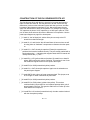
INTRODUCTION TO THE RAMSEY RV1 REVERB EFFECTS:
We're sure at one time or another you wished that your TV had surround
sound during your favorite action move or game, or that you had some reverb
effect on your ham radio or CB, or even that your voice had more depth and
reality. These are not the only effects you can do with this kit, there are many
more. We leave more ideas up to your imagination, as it is rewarding to come
up with your own uses for a neat kit like this.
This kit is designed around an IC that uses a set of switched capacitors
called a bucket brigade device. The IC works just like it sounds, with
successive capacitors ("bucket holders") passing their charges from one to
the next on every clock cycle. When the device is running, it causes a time
delay from input to output determined by the clock rate, and the number of
"bucket holders" that the device has inside. When this delayed sound is fed
back into the input, with some decrease in level, it has a reverb effect such
as echoing in a room. This has the same effect as the old reverb spring units
that were inside of electric guitar amps and other equipment, but is immune
to mechanical shock unlike the spring units.
Not only will you find this kit very useful, you'll also find it enjoyable to build,
whether you are a beginner or an experienced kit builder.
NOTE TO NEWCOMERS: If you are a first time kit builder you may find this
manual easier to understand than you may have expected. Each part in the
kit is checked off as you go, while a detailed description of each part is given.
If you follow each step in the manual in order, and practice good soldering
and kit building skills, the kit is next to fail-safe. If a problem does occur, the
manual will lead you step by step through the troubleshooting guide until you
RV-1 • 4
find the problem and are able to correct it.
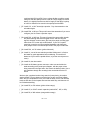
CIRCUIT DESCRIPTION:
Referring to the schematic diagram, you will see the basic layout to the
circuit. You will notice that there are many jumpers in the circuit as well.
These jumpers allow the kit to be configured for various applications. For now
we will talk about using the kit as a surround sound processor, which requires
only JMP 5, and JMP 7 to be in place, and all others left out.
In the surround sound configuration, the inputs are set for line level which is
the level that normally comes out of your tape deck and CD outputs of your
Hi-Fi or radio. Left and right inputs are sent directly to the outputs through R1
and R4, this allows the initial sound to be heard at the same instant it begins.
Both left and right inputs are also added together in U1:A, and amplified or
attenuated depending on the setting of R25. The output of U1:A is then fed
directly to the input of U3, the bucket brigade device (BBD). U2 controls the
BBD, and its clock rate is adjusted by R16. When the clock rate is varied, so
is the delay time of the BBD. The delayed output of U3 is then sent to a
lowpass filter consisting of the U1:C and the surrounding parts. This filter
serves the purpose of removing the clock's tone from the output of the BBD.
Presently it is set up to remove the tone from the lowest clock frequency of
around 3 KHz, but can be altered if a shorter delay is required. The output of
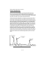
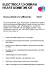
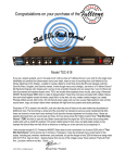
the filter is then sent to the left channel, and some of the output is sent back
to the input to send the same sounds through another cycle for the reverb
effect.
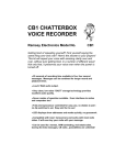
O rig in a l
s ig na l
D e la y e d
s ig na l
S e co nd
r e c y c le
T im
RV-1 • 5
For the surround effect, the output of U1:C, the lowpass filter is sent into an
inverting amplifier to give a signal which is 180 degrees out of phase with the
output of the lowpass filter. When sent into the right channel, this audio will
cancel some of the audio from the left channel at your ears when played
though your speakers. Since the audio that is canceled is from the delayed
sound, not the original sound, it produces an interesting effect of "widening"
the placement of you speakers. Sometimes it seems as if the audio is coming
right out of the walls! S1 switches from the surround effect to the normal
effect. With normal effect, the output of the lowpass filter is sent directly to
both left and right channels.
Other features on this kit provide for many other interesting effects. If JMP2
is placed in along with JMP5 and JMP7, a mono source can be sent into
either left or right inputs, and a stereo simulation will be heard on the left and
right outputs. For a mike input, JMP3, JMP4, JMP6, JMP8, JMP9, and
JMP10 are inserted, and then the Right output is speaker level output from
U4, and Left output is mike level out. If JMP3, JMP4, JMP5, and JMP7 are
inserted, then the unit has a mike in, and a surround effect output at line
level. If JMP5, and JMP7 are inserted, and R1, and R4 removed, then the
outputs are left and right rear channels for a surround system for a television.
This produces an effect like sounds bouncing off of the back of a theatre or
auditorium. Removing R1, and R4 prevents the original audio signal from
arriving at the output, just the delayed signal.
RV-1 • 6
RAMSEY RV-1 REVERB EFFECTS PARTS LIST:
SEMICONDUCTORS
[
[
[
[
]1
]1
]1
]1
LM324 Quad opamp [U1], 14 pin
MN3101 Clock generator driver for BBD [U2], 8 pin
MN3007 1024 Step Bucket Brigade Device [U3], 8 pin
LM386 audio amplifier [U4], 8 pin
CAPACITORS
[
[
[
[
[
[
[
]2
]2
]1
]1
]1
] 10
]2
.01uF disc ceramic (marked .01 or 103 or 10 nF) [C7,17]
.005uF disc ceramic (marked .005 or 502 or 5 nF) [C5,6]
.1uF disc ceramic (marked .1 or 104) [C18]
470pF disc ceramic (marked 470 or 471) [C1]
680pF disc ceramic (marked 680 or 681) [C9]
10uF Electrolytic [C2,3,4,8,10,11,12,13,16,19]
220uF Electrolytic [C14,15]
RESISTORS
[
[
[
[
[
[
[
[
[
[
[
[
]1
]1
]1
]6
]2
]1
]1
]2
]2
] 11
]2
]1
2 ohm resistor (red-black-gold) [R32]
1K ohm resistor (brown-black-red) [R24]
2.2K ohm resistor (red-red-red) [R15]
4.7K ohm resistor (yellow-violet-red) [R1,4,11,13,14,35]
5.6K ohm resistor (green-blue-red) [R26,27]
10K ohm resistor (brown-black-orange) [R20]
33K ohm resistor(orange-orange-orange) [R8]
39K ohm resistor(orange-white-orange) [R6,7]
47K ohm resistor(yellow-violet-orange) [R5,12]
100K ohm resistor (brown-black-yellow) [R2,3,9,10,18,19,21,22,29,31,34]
470K ohm resistor(yellow-violet-yellow) [R17,23]
1M ohm resistor(brown-black-green) [R28]
MISCELLANEOUS
[
[
[
[
[
[
[
[
[
]1
]1
]1
]2
]4
]2
]1
]1
]2
9 Volt battery connector
9 Volt battery clip
Power Jack [J5]
Push Button Switches [S1,2]
RCA Jacks [J1,2,3,4]
200K Small Potentiometers [R25,36]
100K Potentiometer [R16]
10K Potentiometer [R30]
4” pieces of insulated connecting wire
REQUIRED, NOT SUPPLIED
[ ]
[ ]
[ ]
Power source, 9 volt battery or power supply
Audio source such as microphone or stereo
Audio destination such as 4-16 ohm speaker or stereo
OPTIONAL
RV-1 • 7
RAMSEY "LEARN-AS-YOU-BUILD RECORDER ASSEMBLY
STRATEGY"
The RV1 has a fairly compact assembly compared to some of our kits, and for
this reason it is advisable to follow our step by step instructions closely. The
reason being that if you were to install some of the larger components first, there
would be no room to get your fingers in to install some of the smaller components
later. Also while we go along, this manual will describe the purpose of most of the
parts, so you will know exactly what your kit is doing, or meant to do when you
are finished.
We'll start our building in one corner and work our way across, installing the
lower components up to the taller sized components. This will make our placing
and soldering of components easy. As we go along we'll attempt to describe the
circuit operation and the function of many of the parts.
Be sure to read through all of the steps, and check the boxes as you go to be
sure you didn't miss any important steps. Before you switch on the power in a
hurry to see results, check your ICs and capacitors for proper orientation. Also
check the board for any possible solder shorts, or and cold solder joints. All of
these mistakes could have detrimental effects on your kit - not to mention your
ego!
Kit building tips:
Use a good soldering technique - let your soldering iron tip gently heat the traces
to which you are soldering, heat both wires and pads simultaneously. Apply the
solder on the iron and the pad when the pad is hot enough to melt the solder.
The finished joint should look like a drop of water on paper, somewhat soaked in.
Parts are mounted on the top side of the board, that is the side that has no
traces or pads on it.
IC sockets - A good practice, but not necessary in digital or low frequency circuits
such as this. This prevents the horror of desoldering a bad or incorrectly placed
IC.
Part orientation - All parts in the kit are mounted at 90 degree angles to each
other, meaning that all parts are either parallel or perpendicular to the board.
Part installation - when parts are installed, the part is placed flat to the board, and
the leads are bent on the backside of the board to prevent the part from falling
out before soldering. The part is then soldered securely to the board, and the
remaining lead length is then clipped off.
RV-1 • 8
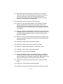
CONSTRUCTION OF THE RV1 REVERB EFFECTS KIT:
The first thing we will do with this kit is check all of our parts and pieces to
make sure we have them all. Use the parts list to do this. If there are any
differences, make sure the schematic agrees with what you have, and also
be aware of the tolerances parts have in a kit. Non-critical parts can vary
quite a bit with almost no effect on kit operation. For example you may get
1uF capacitors in place of 10uF capacitors, or a 100K pot in place of a 10K
pot. No harm done as these will make no difference in kit operation. Use the
parts layout diagram on page 20 to locate parts.
[ ] 1. Install J1, the left input jack, solder all the pins securely to the PC
board for mechanical strength.
[ ] 2. Install J2, J3, and J4 also. We will install them all at once since we will
be using them as "landmark" components to reference the other parts
to.
[ ] 3. Install C2, a 10uF electrolytic capacitor. Electrolytic capacitors are
polarized and must be installed correctly. They are usually marked with a
black stripe and a ( - ) indicating their negative lead, while PC boards will
usually indicate the ( + ) hole.
[ ] 4. Install R4, a 4.7K (yellow-violet-red) resistor. Be careful not to install it
where JMP2 goes as this can be confusing. This resistor is one of two
that sends the original audio from the input to the output.
[ ] 5. Install R19, a 100K (brown-black-yellow) resistor.
[ ] 6. Install C4, a 10uF electrolytic capacitor. Again note its orientation on
the parts layout diagram.
[ ] 7. Install JMP12 with a piece of scrap component lead. This jumper, acts
as a "bridge" for other connections to pass under.
[ ] 8. Install R18, a 100K (brown-black-yellow) resistor.
[ ] 9. Install R23, a 470K resistor (yellow-violet-yellow). This resistor
combined with U1:B provides for a microphone preamp with a gain of
approximately 470 times. This gets the audio level of a mike up to line
level that the circuit requires.
[ ] 10. Install R24 a 1K resistor (brown-black-red), the other resistor involved
with the microphone preamp.
RV-1 • 9
[ ] 11. Install C19, a 10uF electrolytic capacitor. Be sure and check the
orientation before you solder it into place.
[ ] 12. Install R1 a 4.7K resistor (yellow-violet-red).
[ ] 13. Install R2, a 100K resistor (brown-black-yellow).
[ ] 14, install R35, a 4.7K resistor (yellow-violet-red).
[ ] 15. Install R36, one of your 200K ohm trimmer pots. This part combined
with R35, and C19 controls how much feedback is allowed back into
the inputs. This in effect determines how long a delayed signal can
recycle through the circuit.
[ ] 16. Install JMP13 with a piece of scrap component lead.
[ ] 17. Install JMP15 with another piece of scrap.
[ ] 18. Install R10, a 100K resistor (brown-black-yellow).
[ ] 19. Install R11, a 4.7K resistor (yellow-violet-red).
[ ] 20. Install C11, a 10uF electrolytic capacitor, again pay close attention to
orientation.
[ ] 21. Install R25, the other 200K potentiometer.
[ ] 22. Install U1, the larger 14 pin IC marked 324 or LM324. Look at the
parts layout diagram and note where the notch is located. This notch
represents the end where pin 1 of the IC is, so make sure and install
your part with the same orientation as in the circuit diagram. This is the
quad opamp which performs most of the signal conditioning in the
circuit. Be sure and solder all of the pins on the IC, and make sure you
don't have any solder bridges. We sure wouldn't want any solder
bridges to destroy our hard work before we even enjoy a finished kit!
Up to this point we have completed the input mixer, and the microphone
preamp, along with the reverb feedback control. Now is a good time to check
all of your soldering up to this point. Check closely for cold solder joints and
bridges. If desired use a magnifier for this to help you get in close.
We have come a long way, so give your eyes a break and relax a minute.
When we come back we will begin the construction of the part that does the
audio delay, centered around U2 and U3.
RV-1 • 10
[ ] 23. Welcome back! Now we are ready to install R27, a 5.6K resistor
(green-blue-red). Some resistors have a 2% tolerance, so the band
colors are green-blue-red-red, the last band denoting the 2%
tolerance. Be careful as sometimes you may confuse it for another
resistor value by reading the lines backwards.
[ ] 24. Install R26, another 5.6K resistor (green-blue-red).
[ ] 25. Install C8, a 10uF electrolytic capacitor. This capacitor serves the
function of getting rid of some noise on the power source for U2
provided from U3 by "smoothing" out the noise from the operation of
U2, the timer circuit. Pay close attention to the orientation since this is
an electrolytic.
[ ] 26. Install U3, the BBD (marked MN3007). Check all of your solder joints
for bridges and or cold solder joints. This chip is the heart of your kit so
be careful installing it. Make sure that it is oriented according to the
parts layout diagram.
[ ] 27. Install C3, a 10uF electrolytic capacitor, again check orientation. This
capacitor smooths out the noise in the main power supply created by
the running circuits.
[ ] 28. Install R21, a 100K resistor (brown-black-yellow).
[ ] 29. Install R22, another 100K resistor (brown-black-yellow).
[ ] 30. Install C9, a 680pF ceramic capacitor (marked 680 or 681).
[ ] 31. Install R12, a 47K resistor (yellow-violet-orange).
[ ] 32. Install R15, a 2.2K resistor (red-red-red).
[ ] 33. Install U2, the BBD controller chip (marked MN3101). This chip not
only provides the proper duty cycles for clean operation of the BBD,
but also supplies some necessary voltages for the BBD. Make sure all
eight pins are soldered correctly and its orientation is correct.
[ ] 34. Install R28, a 1M resistor (brown-black-green). Caution 1,000,000
ohms!
[ ] 35. Install R31, a 100K resistor (brown-black-yellow).
[ ] 36. Install R29, another 100K resistor (brown-black-yellow). This resistor
RV-1 • 11
combined with R28, and R31 form a voltage divider to split the supply
voltage so that the opamps can be used on a single supply such as a
battery. It is slightly less than one half of supply so that there is plenty
of room for distortion free sound in the opamps and the BBD.
[ ] 37. Install C13, a 10uF electrolytic capacitor. Pay close attention to the
orientation again.
[ ] 38. Install R30, a 10K pot. This pot will control the attenuation if you are to
configure your kit to have a speaker output.
[ ] 39. Install R16, a 100K pot. This pot will control the rate at which signals
are passed through the bucket brigade device, and how long the
signal is delayed. In some cases, R16 may be a panel mounting type
rather than a PC mount style as R30 above. If your R16 is panel
mounting, mount the pot using supplied hardware and simply use
short jumper wires to connect the pot leads to the proper PCB holes.
[ ] 40. Install R14, a 4.7K resistor (yellow-violet-red).
[ ] 41. Install S1, one of the two switches provided. Make sure it is flush to
the board for good appearance before soldering. This switch will
determine if you have the spatial effects, or just the reverb (stereo or
mono).
[ ] 42. Install S2, the other switch.
[ ] 43. Install the 9V battery power connector. make sure and solder the
leads according to the parts layout diagram, with the proper colors
being mounted in the right holes. Also mount the battery holder. Use a
wire lead bent through the mounting holes and soldered to the PC
board.
We have just completed another long stretch of parts placing, how about
another break! This one deserves a soda since we are more than halfway
done. We just completed the timer circuit and the delay circuit, and after this
break we will take on the lowpass filter and the audio amp, and then we will
be finished assembling.
[ ] 44. Install R5, a 47K resistor (yellow-violet-orange).
[ ] 45. Install C5, a .005uF ceramic capacitor (marked 5nF, .005, or 502).
[ ] 46. Install R6, a 39K resistor (orange-white-orange).
RV-1 • 12
[ ] 47. Install C6, another .005uF ceramic capacitor (marked 5nF, .005, or
502).
[ ] 48. Install R7, another 39K resistor (orange-white-orange).
[ ] 49. Install C7, a .01uF ceramic capacitor (marked 103 or .01)
[ ] 50. Install R34, a 100K resistor (brown-black-yellow).
[ ] 51. Install R13, a 4.7K resistor (yellow-violet-red).
[ ] 52. Install R8, a 33K resistor (orange-orange-orange).
[ ] 53. Install C1, a 470pF ceramic capacitor (marked 470 or 471).
You have just completed the lowpass circuit which filters out most of the
frequencies above 3KHz.
[ ] 54. Install R9, a 100K resistor (brown-black-yellow).
[ ] 55. Install R3 a 100K resistor (brown-black-yellow).
[ ] 56. Install R17, a 470K resistor (yellow-violet-yellow). Be careful not to
install it where JMP5 goes.
[ ] 57. Install R20, 10K resistor (brown-black-orange).
[ ] 58. Install R32, a 2 ohm resistor (red-black-gold).
[ ] 59. Install C18, a .1uF ceramic capacitor (marked .1 or 104). This
capacitor combined with R32 prevents the power amp from becoming
a very loud oscillator, which would be good if we were building a siren
kit! Not so good in a reverb kit.
[ ] 60. Install C16, a 10uF electrolytic capacitor. Pay close attention to it's
orientation again.
[ ] 61. Install C10, another 10uF electrolytic capacitor.
[ ] 62. Install C15, a 220uF electrolytic. This capacitor is used to prevent DC
from being applied to a speaker from your audio amp, but allows the
AC audio signal to pass right through. This is the same purpose as
that for C2, C4, C13, C10, and the next part, C12.
[ ] 63. Install C12, a 10uF electrolytic capacitor.
RV-1 • 13
RV-1 • 14
[ ] 64. Install U4, the chip marked 386 (8 pin dip). Pay close attention to it's
orientation and where pin 1 is. This is the audio amplifier chip, and is
used in many of the Ramsey kits.
[ ] 65. Install C17, a .01uF ceramic capacitor (marked .01, 10nF, or 103).
[ ] 66. Install C14, a 220uF to 470uF electrolytic capacitor. This value isn't
entirely critical, but it prevents the power amp from causing the circuit
to oscillate from its current draw on the battery. If you use a power
supply with this kit, the value doesn't need to be so large.
[ ] 67. Install J5, the power jack. Be sure and solder the connections
securely so that it is mechanically secure to the board.
[ ] 68. Install a 4” piece of insulated connecting wire between the holes
marked +Bat.
[ ] 69. Install a 4” piece of insulated connecting wire between the holes
marked -Bat.
Congratulations! you have just finished the assembly of your RV1 kit. All that
needs to be done is to install jumpers to choose what mode of operation you
desire. First choose what you want your inputs to be, you have a choice of a
microphone, or line levels from a stereo or mono source (such as tape or
VCR outputs). Next you choose what sort of output you want. You have two
choices on the right channel, the first being a speaker, and the other is for
line level output. The left channel has a choice between line level and
microphone outputs. Don't worry about what configuration you want,
because it's easy to go back later and change it.
RV-1 • 15
JUMPER INSTALLATION:
This is a point in your kit where you will make a decision in how you wish to
configure your kit. There are several different configurations, and we will chart
them for you.
[ ] CONFIGURING INPUTS:
(concerning JMP2, JMP3, JMP4)
Surround sound for Hi-Fi:
• Install none or...
• Install none and remove R4 and R1 to add to the "rear channel"
effect.
Stereo sound from mono source (such as VCR):
• Install JMP2, all others out.
Mono microphone source:
• Install JMP3, JMP4, all others out. Remove R1, R4, R10, and R2.
[ ] CONFIGURING OUTPUTS:
(concerning JMP5, JMP6, JMP7, JMP8, JMP9, JMP10)
Both outputs line level:
• Install JMP5 and JMP7, all others out.
Microphone level on left output, line on right:
• Install JMP6, all others out.
Speaker output on Right, line on left:
• Install JMP8, JMP9, JMP10, all others out.
Speaker output on right, microphone on left:
• Install JMP6, JMP8, JMP9, JMP10. Only JMP7 is out.
Finally! You've just completed the setup and assembly of your RV1 and now
you're almost ready for a test run. First go over all connections and wiring to
check for any mistakes, you sure wouldn't want to try out your kit in a hurry and
damage something that may not be easy to repair.
RV-1 • 16
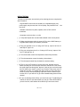
INITIAL TESTING:
To begin our initial tests, we need only a few missing pieces to complete the
whole reverb kit.
• A good 9VDC source such as a battery or a regulated supply. Any
power supply may be used, but if of low quality, may introduce hum
the circuit.
into
• Suitable connectors for power, speaker, mike or RCA to RCA
connectors.
• A speaker, stereo receiver, or mike.
[ ] 1. Verify that all parts are mounted and soldered in the correct places.
[ ] 2. Make sure the power switch is turned off. Plug in the 9VDC battery or
regulated 9VDC supply to the battery connector.
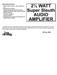
[ ] 3. Plug your speaker in J4, or if using a Hi-Fi set up, “tape in” left into J3
and “tape in” right in J4.
[ ] 4. Plug your microphone into J2, or if using a Hi-Fi set up, “tape out” left
into J1, and right into J2.
[ ] 5. Turn the duration control and amplitude controls fully clockwise.
[ ] 6. Turn the attenuation control clockwise (volume down).
[ ] 7. Turn the speed control fully clockwise for maximum delay.
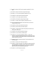
[ ] 8. Turn on your Hi-Fi receiver if you are using one, and then your kit.
Make sure that your receiver's tape selector is switched on. This routes
the audio signal out through the “tape out” jacks of your receiver through
the RV1 back to the “tape in” jacks of your receiver. Play some music or
speak into the mike, you should hear some audio out, along with some
reverb. If you do not hear anything, adjust the volume controls on your
receiver or kit. If you still do not, go to the troubleshooting section of the
manual.
[ ] 9. If you are hearing reverb effects, you are all set to go! Try adjusting the
controls on the kit to see what effects you can get. Some will sound like
you are in a tube, while others will sound like you are on the moon!
RV-1 • 17
If any of these steps did not work as described, go to the trouble-shooting
section of the manual to determine how to resolve the problem.
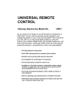
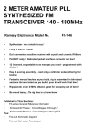
Tape out
left
Lef
t
Tape out
right
Rig
ht
Hi-Fi
Stereo
Listene
r
Back
left
Stereo
Amp
RV1
RV-1 • 18
Back
right
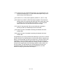
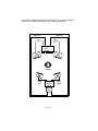
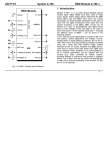
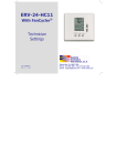
For vocal effects:
M ic ro p h o
ne
R V 1
L
R
T o m ic
i
t
S peak
For stereo simulation:
Mono source
Microphone or VCR
VCR
RV-1
L
R
Amplifier
L
R
RV-1 • 19
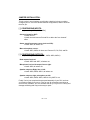
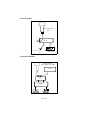
RV-1 PARTS LAYOUT DIAGRAM
RV-1 • 20
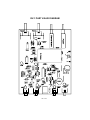
RV-1 PART VALUE DIAGRAM
RV-1 • 21
The Ramsey Kit Warranty
Please read carefully BEFORE calling or writing in about your kit. Most problems can be
solved without contacting the factory.
Notice that this is not a "fine print" warranty. We want you to understand your rights and ours too! All Ramsey
kits will work if assembled properly. The very fact that your kit includes this new manual is your assurance that
a team of knowledgeable people have field-tested several "copies" of this kit straight from the Ramsey
Inventory. If you need help, please read through your manual carefully, all information required to properly
build and test your kit is contained within the pages!
1. DEFECTIVE PARTS: It's always easy to blame a part for a problem in your kit, Before you conclude that a
part may be bad, thoroughly check your work. Today's semiconductors and passive components have reached
incredibly high reliability levels, and it’s sad to say that our human construction skills have not! But on rare
occasions a sour component can slip through. All our kit parts carry the Ramsey Electronics Warranty that they
are free from defects for a full ninety (90) days from the date of purchase. Defective parts will be replaced
promptly at our expense. If you suspect any part to be defective, please mail it to our factory for testing and
replacement. Please send only the defective part(s), not the entire kit. The part(s) MUST be returned to us in
suitable condition for testing. Please be aware that testing can usually determine if the part was truly defective
or damaged by assembly or usage. Don't be afraid of telling us that you 'blew-it', we're all human and in most
cases, replacement parts are very reasonably priced.
2. MISSING PARTS: Before assuming a part value is incorrect, check the parts listing carefully to see if it is a
critical value such as a specific coil or IC, or whether a RANGE of values is suitable (such as "100 to 500 uF").
Often times, common sense will solve a mysterious missing part problem. If you're missing five 10K ohm
resistors and received five extra 1K resistors, you can pretty much be assured that the '1K ohm' resistors are
actually the 'missing' 10 K parts ("Hum-m-m, I guess the 'red' band really does look orange!") Ramsey
Electronics project kits are packed with pride in the USA. If you believe we packed an incorrect part or omitted
a part clearly indicated in your assembly manual as supplied with the basic kit by Ramsey, please write or call
us with information on the part you need and proof of kit purchase
3. FACTORY REPAIR OF ASSEMBLED KITS:
To qualify for Ramsey Electronics factory repair, kits MUST:
1. NOT be assembled with acid core solder or flux.
2. NOT be modified in any manner.
3. BE returned in fully-assembled form, not partially assembled.
4. BE accompanied by the proper repair fee. No repair will be undertaken until we have received the MINIMUM
repair fee (1/2 hour labor) of $18.00, or authorization to charge it to your credit card account.
5. INCLUDE a description of the problem and legible return address. DO NOT send a separate letter; include
all correspondence with the unit. Please do not include your own hardware such as non-Ramsey
cabinets, knobs, cables, external battery packs and the like. Ramsey Electronics, Inc., reserves the
right to refuse repair on ANY item in which we find excessive problems or damage due to
construction methods. To assist customers in such situations, Ramsey Electronics, Inc., reserves the
right to solve their needs on a case-by-case basis.
The repair is $36.00 per hour, regardless of the cost of the kit. Please understand that our technicians are not
volunteers and that set-up, testing, diagnosis, repair and repacking and paperwork can take nearly an hour of
paid employee time on even a simple kit. Of course, if we find that a part was defective in manufacture, there
will be no charge to repair your kit (But please realize that our technicians know the difference between a
defective part and parts burned out or damaged through improper use or assembly).
4. REFUNDS: You are given ten (10) days to examine our products. If you are not satisfied, you may return
your unassembled kit with all the parts and instructions and proof of purchase to the factory for a full refund.
The return package should be packed securely. Insurance is recommended. Please do not cause needless
delays, read all information carefully.
RV-1 • 22
RV-1 REVERB AND SURROUND EFFECTS
Quick Reference Page Guide
Introduction to the RV-1 ...................
Circuit description .............................
Parts list ............................................
RV-1 Assembly instructions..............
Initial testing......................................
Troubleshooting ................................
Using the RV-1 .................................
Parts Layout diagram .......................
Parts value diagram..........................
Schematic diagram ...........................
Warranty information ........................
REQUIRED TOOLS
• Soldering Iron (Radio Shack #RS64-2072)
• Thin Rosin Core Solder (RS64-025)
• Needle Nose Pliers (RS64-1844)
• Small Diagonal Cutters (RS64-1845)
• <OR> Complete Soldering Tool Set
(RS64-2801)
ADDITIONAL SUGGESTED ITEMS
Soldering Iron Holder/Cleaner
•
(RS-64-
Price: $5.00
Ramsey Publication No. MRV-1
Assembly and Instruction manual for:
RAMSEY MODEL NO.
RAMSEY ELECTRONICS, INC.
793 Canning Parkway
Victor, New York 14564
Phone (716) 924-4560
Fax (716) 924-4555
RV-1 • 23
4
5
7
9
16
17
18
20
21
22
23
TOTAL SOLDER POINTS
219
ESTIMATED ASSEMBLY
TIME
Beginner .............. 4.7 hrs
Intermediate ......... 2.7 hrs
Advanced ............. 2.0 hrs