1
8
273 Branchport Avenue
Long Branch, N.J. 07740
(732) 222-6880
Thank you for using our products.
INSTALLATION INSTRUCTIONS
SPEAKER AMPLIFIER
Use this product according to this instruction manual. Please keep this instruction manual for future reference.
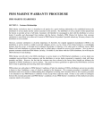
MODEL NUMBERS:
SA-70
SA-90
SA-C8-A
SA-B4
4"
4"
8"
4"
SPEAKER WITH SQUARE, FLUSH GRILLE
SPEAKER WITH ROUND, FLUSH GRILLE
SPEAKER WITH ROUND, FLUSH, PLASTIC GRILLE
SPEAKER IN A SURFACE MOUNT HOUSING
FCC REGULATIONS:
This equipment complies with Part 68 of the FCC Rules. On the back of this equipment is a label that contains, among other
information, the FCC Registration Number and the Ringer Equivalence Number (REN) for this equipment. You must, upon request
provide this information to your telephone company.
The REN is also useful to determine the quantity of devices that you may connect to your telephone line and still have all of those
devices ring when your telephone number is called. In most, but not all areas, the sum of the REN's of all devices connected to one
line should not exceed five (5.0). To be certain of the number of devices that you may connect to your line, you may want to contact
your local telephone company.
Should the equipment cause harm to the telephone network, the telephone company shall, if possible, notify the customer that
temporary discontinuance of service may be required; however, where prior written notice is not possible, the telephone company
may temporarily discontinue service without notice, if such action is necessary under the circumstances. The telephone company may
make changes in its communication facilities, equipment and operations procedures, where such action is reasonably required in the
operation of its business and is not inconsistent with the rules and regulations of the Federal Communications Commission.
Do not attempt to repair or modify this equipment. Repairs to this product will be performed by Wheelock Inc. 273 Branchport Ave,
Long Branch, NJ 07740 in accordance with Wheelock Inc.'s published Terms and Conditions of Sale. This equipment should not be
used on coin telephone lines. Connection to party line service is subject to state tariffs.
If trouble is experienced, disconnect this equipment from the telephone line to determine if it is causing the malfunction. If the
equipment is determined to be malfunctioning, its use shall be discontinued until the problem has been corrected.
NOTE: All CAUTIONS and WARNINGS are identified by the symbol
. All warnings are printed in bold capital letters.
WARNING: READ THESE INSTRUCTIONS CAREFULLY. FAILURE TO COMPLY WITH ANY OF THE
FOLLOWING INSTRUCTIONS, CAUTIONS AND WARNINGS COULD RESULT IN IMPROPER APPLICATION,
INSTALLATION AND/OR OPERATION OF THESE PRODUCTS IN AN EMERGENCY SITUATION, WHICH COULD
RESULT IN PROPERTY DAMAGE AND SERIOUS INJURY OR DEATH TO YOU AND/OR OTHERS.
Copyright 1987-1994, 1997 Wheelock, Inc. All rights reserved.
APPLICATION INFORMATION:
P81416 T
Sheet 1 of 10
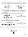
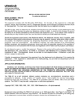
The Speaker Amplifiers are used in the following manner. Figure 1 shows a zone paging application used with Wheelock's Zone
Page Control Module. The Speaker Amplifier can also be used to provide single-zone paging when connected directly to an unused
C.O. line port, which can be programmed to function as a 600 OHM Audio Page Port. (i.e,. does not require Talk Battery). See
Figure 2.
Figure 1.
Figure 2.
(See Note 2 below)
NOTES
1.
Some telephone systems require that the C.O. trunk port (loop start) or C.O. line port be equipped with a trunk card, page
card or other equipment. Consult the telephone manufactures system manual for equipment or programming required.
2.
If unused C.O. port requires talk battery to pass audio (most do), then a Wheelock Zone Control is required as an interface
for Zoned Paging Systems. For Single-Zone Paging a Wheelock PRM-150 Preamplifier with an RPS-2406 Power Supply is
required as an interface.
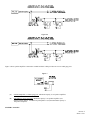
Figure 3 shows a speaker amplifier connected to a tone generator for telephone alerting or night ringing, with paging.
Figure 3.
NOTE
If unused C.O. port requires talk battery, to pass
audio (most do), then a Wheelock Zone Control is
required as an interface.
Figure 4 shows the same tone generator and speaker amplifier activated by a common audible.
Figure 4.
NOTE
If unused C.O. port requires talk battery, to pass
audio (most do), then a Wheelock Zone Control is
required as an interface.
The speaker amplifier can be used to amplify the tone of a telephone as shown in Figure 5. It can also be used to expand the
capability of 25 or 70 volt paging systems. Up to 125 speaker amplifiers may be connected to each transformer using the 1/4W tap.
See Figures 6 & 6A.
Figure 5.
Figure 6.
P81416 T
Sheet 2 of 10
Figure 6A.
Figure 7 shows speaker amplifiers connected to a PABX or EKSU which provides one or more audio page ports.
Figure 7.
(A)
8 OHM, Amplified (1-3 Watts) page port: Maximum capacity is 125 speaker amplifiers.
(B)
600 OHM, low power page port: Maximum capacity is 10 speaker amplifiers (See
System Capacity below). If a PRM-150 preamplifier is used, then maximum capacity is
150 speaker amplifiers.
SYSTEM CAPACITY:
P81416 T
Sheet 3 of 10
In each application (except Figures 6, 6A and 7), a maximum of 10 speaker amplifiers may be used, based upon a minimum audio
input signal of -15dBM (0.1VRMS) at each speaker amplifier to obtain rated power output. Depending upon the paging system's
configuration, and the available audio output signal from the host telephone system, the audio input signal may be less. If additional
volume is required, use the Wheelock PRM-150 Preamplifier. Applications with up to 150 speaker amplifiers also require the PRM150 Preamplifier.
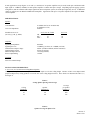
SPECIFICATIONS:
SpeakerCone Diameter:
4" (Models SA-70, SA-90 & SA-B4)
8" (Model SA-C8-A)
45 Ohms
Voice Coil Impedance:
Sound Pressure Level
(On Axis, @ 1W, @ 1KHz):
SA-70, SA-90, SA-B4
1M. 95
4FT. 93
10FT. 85
SA-C8-A
98
96
88
AmplifierSignal Input Impedance:
Signal Input Level:
Nominal Power Input Voltage:
Nominal Input Current:
Maximum Input Current:
Power Output Rating:
600 Ohms
-15 dBM (@ 0.1Vrms) to +10 dBM (2.4Vrms)
24VDC (18VDC minimum; 28VDC maximum)
45 mA (@ 24VDC)
170 mA (@24VDC)
1.0 Watt
Terminals4 Screw Terminal Clamps
INSTALLATION INFORMATION:
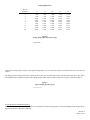
A. SA-C8-A, SA-70, and SA-90 Ceiling Mount Speakers
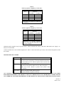
Ceiling mounted speakers should be spaced at a distance equal to twice the ceiling height. Because of their cone shaped sound
projection (dispersion), ceiling speakers cover more area as the ceiling height increases. These factors are illustrated in Tables 1, 2,
and Figure 8.
Table 1:
Ceiling Speaker Spacing And Coverage
Ceiling
Height (ft.)
8
10
12
Speaker
Spacing (ft.)
16
20
24
Coverage
per speaker
(square ft.)
250
400
575
Table 2:
Speaker Coverage In Square Feet
P81416 T
Sheet 4 of 10
Ceiling Height (Feet)
No. Of
Speakers
1
2
3
4
5
6
7
8
9
10
8
250
500
750
1,000
1,250
1,500
1,750
2,000
2,250
2,500
9
325
650
975
1,300
1,625
1,950
2,275
2,600
2,925
3,250
10
400
800
1,200
1,600
2,000
2,400
2,800
3,200
3,600
4,000
11
485
970
1,450
1,930
2,410
2,890
3,370
3,850
4,330
4,810
12
575
1,150
2,300
2,875
3,450
4,025
4,600
5,175
5,750
6,325
Figure 8.
Ceiling Speaker Spacing And Coverage
Note that increasing volume results in the speaker being louder in its covered area, but does not increase the area covered by the
speaker.
The design goal of speaker placement is to allow people to hear just about the same volume from anywhere in the room. The goal is
accomplished with a symmetrical layout of the ceiling speakers which achieves edge-to-edge area coverage, as shown in Figure 9.
Figure 9.
Typical Ceiling Speaker Layout
B. SA-B4 Surface Wall Mount Speakers:
Surface wall mounted speakers are used where it is not practical to mount ceiling speakers. Forward sound projection and spacing are
important, and Table 3 provides a guide line.
P81416 T
Sheet 5 of 10
Table 3:
Wall Speaker Forward Projection And Spacing
Mounting Height (Ft.)
8
12
Forward Projection (Ft.)
30
35
Spacing (Ft.)
20
25
Wall speakers should be mounted on the same wall, as long as they are not required to project sound more than shown in Table 3
above. Figure 10 is typical for a required 30 foot sound projection (speaker mounted 8 feet high).
Figure 10.
Wall Speaker Layout
Speakers Mounted On One Wall
Whenever possible, wall mounted speakers should be aimed in the same direction, when required to project further than 30 or 35 feet.
Pillars or posts are often available to facilitate this type of installation. Although the pillar locations will vary, Figure 11 provides a
useful guide. Note that a stagger pattern should be maintained.
Figure 11.
Wall Speaker Layout
Speakers Mounted On One Wall And Pillars
If pillars or posts are not available, then wall speakers can be mounted on opposing walls, and a stagger pattern must be maintained as
shown in Figure 12.
Figure 12.
Wall Speaker Layout
Speakers Mounted On Opposing Walls
P81416 T
Sheet 6 of 10
Insert volume control shaft and set the volume approximately mid-way. (see Figure 13 and 14). As the system is put into service
readjust as necessary. If you want to prevent tampering of the control, simply pull out the volume control shaft. With the shaft
removed, volume can still be adjusted using a 5/64" hex drive. Shaft can be reinstalled later if necessary.
MOUNTING INFORMATION:
The SA-B4 is designed to mount on the surface of a wall. Remove the top cover by pushing the latch at the bottom of the housing
base with a small screwdriver, see Figure 14. Disconnect the speaker wires by unplugging them from the P.C. Board pins P1 (red)
and P2 (black). Figure 15 is the mounting template. Simply locate the template at the desired location and mount the base to the wall
with the screws provided. Connect wires as specified in "WIRING INFORMATION" on page 9, and then snap cover back onto base.
Be sure that the base sides line up between the cover sides and the 4 fingers on the cover sides, see Figure 16.
Figure 13.
SA-C8-A, SA-70, SA-90
Figure 14: SA-B4
Figure 15.
P81416 T
Sheet 7 of 10
Figure 16.
The SA-70 and SA-90 are designed to mount flush in a wall or in the ceiling. For ceiling mounting, a speaker support bracket is
available (Wheelock's Model Number SSB-4), see Figure 17. For wall or ceiling mounting, use a 4" square by 1-1/2" deep backbox
with a 4" square 1-1/2" deep extension ring, see Figure 19.
The SA-C8-A is designed to mount flush in the ceiling. A speaker support bracket, (Wheelock's Model Number SSB-8) and a
backbox (Wheelock's model number CBB-8) are available. See Figure 18.
Figure 17.
Figure 18.
Figure 19.
WIRING INFORMATION:
Use "D" type station wire (24 AWG) or other suitable wire. Table 4 is a guide for the number of speaker amplifiers per audio pair
run, and Table 5 is a guide for the number of speaker amplifiers per power pair run.
P81416 T
Sheet 8 of 10
Table 4:
Number of Speaker Amplifiers per Audio Pair*
Wire Run
(Ft.)
Number of Speaker
Amplifiers
22 AWG
24 AWG
100
150
120
200
150
120
400
100
60
800
50
30
1600
25
15
* Based upon using Wheelock's PRM-150
Preamplifier
Table 5:
Number of Speaker Amplifiers per Power Pair
Wire Run
(Ft.)
Number of Speaker
Amplifiers
22 AWG
24 AWG
100
*33
*20
200
*20
*13
400
10
6
800
5
3
1600
2
1
* Maximum of 12 Speaker Amplifiers
when using Wheelock RPS-2406 600
mA Power Supply.
Although speaker amplifiers may be powered form a 24VDC unfiltered "B" battery, Wheelock's RPS-2406 Power Supply ("A"
battery) is recommended.
Connect the audio lines to the terminals designated as T and R. Connect the 24VDC power lines to the terminals designated as GND
and -24VDC.
TROUBLESHOOTING CHART:
Problem
No sound
Possible Cause and Correction
1) Is the volume control turned up (clockwise).
2) Check presence and polarity of -24VDC and GND at the speaker.
3) Check audio level on T and R at speaker, and if necessary also at
the audio source.
Low volume
1) Check that volume control is turned up.
2) Check for the sufficient audio level on T & R at the speaker.
3) Be sure at least -18VDC is present at the speaker during
operation.
Loud squeal
1) Lower volume setting of speaker.
(Feed back)
2) Move the phone farther from the speaker.
3) Install confidencer in phone if necessary.
ANY MATERIAL EXTRAPOLATED FROM THIS DOCUMENT OR FROM WHEELOCK MANUALS OR OTHER
DOCUMENTS DESCRIBING THE PRODUCT FOR USE IN PROMOTIONAL OR ADVERTISING CLAIMS, OR FOR
ANY OTHER USE, INCLUDING DESCRIPTION OF THE PRODUCT'S APPLICATION, OPERATION, INSTALLATION
P81416 T
Sheet 9 of 10
AND TESTING IS USED AT THE SOLE RISK OF THE USER AND WHEELOCK WILL NOT HAVE ANY LIABILITY
FOR SUCH USE.
CAUTION: These devices are not intended for use in hazardous locations as defined by the National Electrical Code (NEC) and
by the National Fire Protection Association (NFPA).
Limited Warranty
Wheelock products must be used within their published specifications and must be PROPERLY specified, applied, installed, operated,
maintained and operationally tested in accordance with these instructions at the time of installation and at least twice a year or more
often and in accordance with local, state and federal codes, regulations and laws. Specification, application, installation, operation,
maintenance and testing must be performed by qualified personnel for proper operation in accordance with all of the latest National
Fire Protection Association (NFPA), Underwriters' Laboratories (UL), Underwriters’ Laboratories of Canada (ULC), National
Electrical Code (NEC), Occupational Safety and Health Administration (OSHA), local, state, county, province, district, federal and
other applicable building and fire standards, guidelines, regulations, laws and codes including, but not limited to, all appendices and
amendments and the requirements of the local authority having jurisdiction (AHJ). Wheelock products when properly specified,
applied, installed, operated, maintained and operationally tested as provided above are warranted against mechanical and electrical
defects for a period of three years from date of manufacture (as determined by date code). Correction of defects by repair or
replacement shall be at Wheelock's sole discretion and shall constitute fulfillment of all obligations under this warranty. THE
FOREGOING LIMITED WARRANTY SHALL IMMEDIATELY TERMINATE IN THE EVENT ANY PART NOT FURNISHED BY
WHEELOCK IS INSTALLED IN THE PRODUCT. THE FOREGOING LIMITED WARRANTY SPECIFICALLY EXCLUDES ANY
SOFTWARE REQUIRED FOR THE OPERATION OF OR INCLUDED IN A PRODUCT. WHEELOCK MAKES NO REPRESENTATION OR
WARRANTY OF ANY OTHER KIND, EXPRESS, IMPLIED OR STATUTORY WHETHER AS TO MERCHANTABILITY, FITNESS FOR A
PARTICULAR PURPOSE OR ANY OTHER MATTER.
USERS ARE SOLELY RESPONSIBLE FOR DETERMINING WHETHER A PRODUCT IS SUITABLE FOR THE USER'S PURPOSES, OR
WHETHER IT WILL ACHIEVE THE USER'S INTENDED RESULTS. THERE IS NO WARRANTY AGAINST DAMAGE RESULTING
FROM MISAPPLICATION, IMPROPER SPECIFICATION, ABUSE, ACCIDENT OR OTHER OPERATING CONDITIONS BEYOND
WHEELOCK'S CONTROL.
SOME WHEELOCK PRODUCTS CONTAIN SOFTWARE. WITH RESPECT TO THOSE PRODUCTS, WHEELOCK DOES NOT
WARRANTY THAT THE OPERATION OF THE SOFTWARE WILL BE UNINTERRUPTED OR ERROR-FREE OR THAT THE SOFTWARE
WILL MEET ANY OTHER STANDARD OF PERFORMANCE, OR THAT THE FUNCTIONS OR PERFORMANCE OF THE SOFTWARE
WILL MEET THE USER'S REQUIREMENTS. WHEELOCK SHALL NOT BE LIABLE FOR ANY DELAYS, BREAKDOWNS,
INTERRUPTIONS, LOSS, DESTRUCTION, ALTERATION, OR OTHER PROBLEMS IN THE USE OF A PRODUCT ARISING OUT OF OR
CAUSED BY THE SOFTWARE.
THE LIABILITY OF WHEELOCK ARISING OUT OF THE SUPPLYING OF A PRODUCT, OR ITS USE, WHETHER ON WARRANTIES,
NEGLIGENCE, OR OTHERWISE, SHALL NOT IN ANY CASE EXCEED THE COST OF CORRECTING DEFECTS AS STATED IN THE
LIMITED WARRANTY AND UPON EXPIRATION OF THE WARRANTY PERIOD ALL SUCH LIABILITY SHALL TERMINATE.
WHEELOCK IS NOT LIABLE FOR LABOR COSTS INCURRED IN REMOVAL, REINSTALLATION OR REPAIR OF THE PRODUCT BY
ANYONE OTHER THAN WHEELOCK OR FOR DAMAGE OF ANY TYPE WHATSOEVER, INCLUDING BUT NOT LIMITED TO, LOSS
OF PROFIT OR INCIDENTAL OR CONSEQUENTIAL DAMAGES. THE FOREGOING SHALL CONSTITUTE THE SOLE REMEDY OF
THE PURCHASER AND THE EXCLUSIVE LIABILITY OF WHEELOCK.
IN NO CASE WILL WHEELOCK'S LIABILITY EXCEED THE PURCHASE PRICE PAID FOR A PRODUCT.
Limitation of Liability
WHEELOCK'S LIABILITY ON ANY CLAIM OF ANY KIND, INCLUDING NEGLIGENCE AND BREACH OF WARRANTY, FOR ANY
LOSS OR DAMAGE RESULTING FROM, ARISING OUT OF, OR CONNECTED WITH THIS CONTRACT, OR FROM THE
MANUFACTURE, SALE, DELIVERY, RESALE, REPAIR OR USE OF ANY PRODUCT COVERED BY THIS ORDER SHALL BE LIMITED
TO THE PRICE APPLICABLE TO THE PRODUCT OR PART THEREOF WHICH GIVES RISE TO THE CLAIM. WHEELOCK'S LIABILITY
ON ANY CLAIM OF ANY KIND SHALL CEASE IMMEDIATELY UPON THE INSTALLATION IN THE PRODUCT OF ANY PART NOT
FURNISHED BY WHEELOCK. IN NO EVENT SHALL WHEELOCK BE LIABLE FOR ANY CLAIM OF ANY KIND UNLESS IT IS
PROVEN THAT OUR PRODUCT WAS A DIRECT CAUSE OF SUCH CLAIM. FURTHER, IN NO EVENT, INCLUDING IN THE CASE OF A
CLAIM OF NEGLIGENCE, SHALL WHEELOCK BE LIABLE FOR INCIDENTAL OR CONSEQUENTIAL DAMAGES. SOME STATES DO
NOT ALLOW THE EXCLUSION OR LIMITATION OF INCIDENTAL OR CONSEQUENTIAL DAMAGES, SO THE PRECEDING
LIMITATION MAY NOT APPLY TO ALL PURCHASERS.
6/97
P81416 T
Sheet 10 of 10