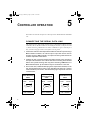
1
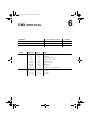
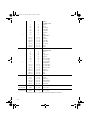
User.fm Page 1 Monday, April 17, 2000 11:22 AM
RoboColor Pro 400
users guide
User.fm Page 2 Monday, April 17, 2000 11:22 AM
INTRODUCTION . . . . . . . . . . . . . . . . . . . . . . . . . . . . . . 3
SAFETY . . . . . . . . . . . . . . . . . . . . . . . . . . . . . . . . . . . 4
INSTALLATION . . . . . . . . . . . . . . . . . . . . . . . . . . . . . . . 6
STAND-ALONE OPERATION . . . . . . . . . . . . . . . . . . . . . 7
CONTROLLER OPERATION . . . . . . . . . . . . . . . . . . . . . . 8
DMX PROTOCOL . . . . . . . . . . . . . . . . . . . . . . . . . . . 11
SERVICE . . . . . . . . . . . . . . . . . . . . . . . . . . . . . . . . . 13
SPECIFICATIONS . . . . . . . . . . . . . . . . . . . . . . . . . . . . 15
© 1998, 2000 Martin Professional A/S, Denmark.
All rights reserved. No part of this manual may be
reproduced, in any form or by any means, without
permission in writing from Martin Professional A/S,
Denmark.
Printed in Denmark.
P/N 35000062, Rev. B
User.fm Page 3 Monday, April 17, 2000 11:22 AM
I NTRODUCTION
1
Congratulations on your choice of the RoboColor Pro 400, a professional high
performance, intelligent lighting projector that features:
• 200 Watt MSD lamp
• 32 different colors + white (including 'cold' and 'hot' filter)
• 0 to 100% smooth dimming
• High speed shutter for 'instant' blackout and very fast strobe
• 3 field angle gobos plus wash-effect
• Lamp can be remotely switched on and off in order to prolong lamp life
• Multi-coated precision optics with adjustable focus
• Can be controlled via DMX 512 Desk or Martin Controller
• Stand alone chase with or without music trig
• Power Factor Correction to allow low current consumption
• Efficient fan cooling and over-heat protection
This user's guide describes the features in firmware version 6.5. The latest
information about the RoboColor Pro 400 is available from the Martin web site at
http://www.martin.dk.
3
User.fm Page 4 Monday, April 17, 2000 11:22 AM
SAFETY
Warning!
2
This product is for professional use only. It is not for household
use.
This product presents risks of lethal or severe injury due to fire and heat, electric
shock, ultraviolet radiation, lamp explosion, and falls. Read this manual before
powering or installing the fixture, follow the safety precautions listed below and
observe all warnings in this manual and printed on the fixture. If you have questions
about how to operate the fixture safely, please contact your Martin dealer or call the
Martin 24-hour service hotline at +45 70 200 201.
To prot ect yoursel f and ot hers fr om elect ric shock
• Disconnect the fixture from AC power before removing or installing the lamp,
fuses, or any part, and when not in use.
• Always ground (earth) the fixture electrically.
• Use only a source of AC power that complies with local building and electrical
codes and has both overload and ground-fault protection.
• Do not expose the fixture to rain or moisture.
• Refer any service operation not described in this manual to a qualified technician.
To prot ect yoursel f and ot hers fr om UV radiat ion and lamp
explosion
• Never operate the fixture with missing or damaged lenses and/or covers.
• When replacing the lamp, allow the fixture to cool for at least 5 minutes before
opening the fixture or removing the lamp. Protect your hands and eyes with gloves
and safety glasses.
• Do not stare directly into the light. Never look at an exposed lamp while it is lit.
• Replace the lamp if it becomes defective or worn out, or before usage exceeds the
maximum service life.
4
User.fm Page 5 Monday, April 17, 2000 11:22 AM
To protect yourself and other s f rom burns and f ire
• Never attempt to bypass the thermostatic switch or fuses. Always replace defective
fuses with ones of the specified type and rating.
• Keep all combustible materials (for example fabric, wood, paper) at least 0.1 meters
(4 inches) away from the fixture. Keep flammable materials well away from the
fixture.
• Do not illuminate surfaces within 0.3 meters (12 inches) of the fixture.
• Provide a minimum clearance of 0.1 meters (4 inches) around fans and air vents.
• Never place filters or other materials over the lens.
• The exterior of the fixture can reach temperatures up to 65° C (150° F). Allow the
fixture to cool for at least 5 minutes before handling.
• Do not modify the fixture or install other than genuine Martin parts.
• Do not operate the fixture if the ambient temperature (Ta) exceeds 40° C (104° F).
To protect yourself and other s f rom injury due to f all s
• When suspending the fixture above ground level, verify that the structure can hold
at least 10 times the weight of all installed devices.
• Verify that all external covers and rigging hardware are securely fastened and use an
approved means of secondary attachment such as a safety cable.
• Block access below the work area whenever installing or removing the fixture.
5
User.fm Page 6 Monday, April 17, 2000 11:22 AM
INSTALLATION
3
The RoboColor Pro 400 package includes mounting bracket and fittings, 3-pin XLR
data cable, mains cable, and this users guide. The fixture is adjusted at the factory so
that only a few basic procedures are necessary before the fixture is ready for use.
Warning!
Disconnect the unit from AC power before proceeding.
Important! Verify that the voltage and frequency settings match your power
supply before connecting to power.
INSTALL LAMP
The Philips MSD 200 is the only lamp approved for use in the RoboColor Pro 400.
1 Remove the 3 thumbscrews that secure the access plate of the lamp socket
assembly at the rear of the RoboColor and withdraw the lamp socket assembly.
2 Hold the Philips MSD 200 lamp (not included) in a clean cloth to avoid
contaminating the glass bulb and carefully insert it into the socket. Clean the
lamp with the alcohol wipe packaged with the lamp.
3 Replace the lamp socket assembly and tighten the thumbscrews.
See also the lamp alignment procedure on page 13.
INSTALL MOUNTING BRACKET
The bracket allows you to turn or tilt the RoboColor to the desired position.
1 On each side of the RoboColor is a stud for the mounting bracket. Fit a plastic
washer, a star washer, and then the mounting bracket onto these studs.
2 Lock the mounting bracket using the two lever handles.
CONNECT TO POWER
If there is no plug on the mains cable, you must install one that fits your mains
outlet before connecting the fixture to power.
•
Connect the brown wire to the LIVE pin, connect the blue wire to the NEUTRAL
pin and connect the yellow/green wire to the EARTH pin (ground).
6
User.fm Page 7 Monday, April 17, 2000 11:22 AM
STAND- ALONE OPERATION
4
The RoboColor Pro 400 may be operated in stand-alone mode without a controller.
Music-trigger uses a built in microphone for sound-activated control and autotrigger runs at a preset speed using an internal trig source.
1 Use the DIP-switch on the rear panel to select a trigger type. To select musictrigger, set DIP-switch pins 1, 2, and 10 to ON. To select auto-trigger, set DIPswitch pins 2 and 10 to ON. Set all other pins to OFF.
2 Switch on the unit to perform the chosen program.
Note: Some programs shown below are for service use only. Do not use them for
light shows.
Program
Pin(s) switched ON
Protocol auto-detect (DMX 512 / Martin RS-485)
Stand Alone Auto-trig
Stand Alone Music-trig
Lamp ON (for lamp adjustment)
Mechanical stop (for service use only)
Adjustment (for service use only)
L.E.D. Chase Auto-trig (for service use only)
L.E.D. Chase Music-Trig (for service use only)
All pins switched ON
2, 10
1, 2, 10
8, 10
5, 10
1, 5, 10
4, 10
1, 4, 10
Table 1: Stand-alone program settings
7
User.fm Page 8 Monday, April 17, 2000 11:22 AM
5
CONTROLLER OPERATION
The RoboColor Pro 400 accepts two control protocols: Martin RS-485 and DMX
512.
CONNECTING THE SERIAL DATA LINK
The RoboColor Pro 400’s XLR connections are configured for Martin protocol
controllers, that is, the data sockets are wired with pin 2 to hot (+) and pin 3 to cold
(-). When connecting a RoboColor Pro 400 to a DMX device (pin 2 cold and pin 3
hot), you must swap pins 2 and 3 with a phase-reversing cable.
1 Connect the controller’s data output to the RoboColor Pro 400’s input. If using a
Martin-standard controller, use a direct 3-pin to 3-pin cable such as the one
provided. If using a DMX controller, use a phase-reversing cable that fits the
controller output. See cables below.
2 Continue the link: connect the output of the fixture closest to the controller to
the input of the next fixture. Use a direct cable when connecting same-standard
fixtures. Use a phase-reversing cable only when connecting a DMX device to a
Martin-standard device. Up to 32 fixtures may be connected on a serial link.
3 Insert a male 120 Ω XLR termination plug in the output of the last fixture on the
link. The termination plug is simply a 3-pin male XLR plug with a 120 Ω resistor
soldered between pins 2 and 3. The termination plug is required for error-free
communication.
3-pin to 3-pin
Phase Reversing
Cable
5-pin to 3-pin
Phase Reversing
Cable
3-pin to 5-pin
Phase Reversing
Cable
Connections
Connections
Connections
Male
Female
Male
Female
Male
Female
1
2
3
1
2
3
1
2
3
4
5
1
2
3
1
2
3
1
2
3
4
5
P/N 11820006
8
P/N 11820003
P/N 11820002
User.fm Page 9 Monday, April 17, 2000 11:22 AM
ADDRESS SETTING
The DIP-switch on the rear panel is used to select the control address on which the
RoboColor Pro 400 responds to the controller. The control address, also known as
the start channel, is the first channel used to receive instructions from the controller.
For independent control, each fixture must have a unique control address and nonoverlapping control channels.
The total number of channels required depends on the operation mode. The
RoboColor Pro 400 requires 1 channel (from 1 to 32) when operated via a Martin
lighting controller. It requires 7 channels when using DMX mode 2 (DMX vector
control) and 5 channels in DMX modes 1 and 3.
The control address is selected by switching ON one or more DIP-switch pins. Each
pin that you switch ON adds the value listed in the following table. Pins that you
switch OFF add no value. The control address is determined by adding the values of
pins 1 to 9. Pin 10 is always switched OFF.
Example 1: Pin 1, 2 and 5 ON = 1 + 2 + 0 + 0 + 16 + 0 + 0 + 0 + 0 = ch. 19.
Example 2: Pin 2, 3, 7 and 8 ON = 0 + 2 + 4 + 0 + 0 + 0 + 64 + 128 + 0 = ch. 198.
Pin No
Value
Pin No
Value
1
1
6
32
2
2
7
64
3
4
8
128
4
8
9
256
5
16
10
Always OFF for
address setting
Table 2: DIP-switch values
OPERATION
The fixture detects whether the data is from a DMX or a Martin controller and
responds accordingly. It is possible to re-activate the auto detect function by
switching on all ten DIP-switches and then re-selecting the address.
1 Use the DIP-switch to select the desired control address for each fixture.
Ensure that none of the RoboColors are set to stand-alone mode.
2 Switch on and configure the controller.
3 Apply power to the RoboColors. After a short start-up routine, the RoboColors
are ready to respond to commands from the controller.
9
User.fm Page 10 Monday, April 17, 2000 11:22 AM
ABOUT FAN CONTROL
Beginning with CPU firmware version 6.5, fan control is completely automatic. The
fan operates as follows:
• Fan speed is automatically reduced to 50% after protocol detection and the fan stops
1 minute later if the lamp is still off.
• When the lamp is on, the fan runs at the full speed.
• Fan speed reduces to 50% when the lamp is turned off and the fan stops completely
1 minute later.
10
User.fm Page 11 Monday, April 17, 2000 11:22 AM
6
DMX PROTOCOL
DMX Mode
PL11 Jumper Location
Channels
Mode 1: Tracking (DEFAULT)
No jumper
5
Mode 2: Vector
Pin 4 and 5
7
Mode 3: Tracking + Lamp Off via DMX
Pin 5 and 6
5
Channel
1
2
DMX Value
Percent
Effect
0-3
4-7
8-199
200-218
219-238
239-248
249-252
253-255
0-1
2-3
3-78
78-85
86-93
94-97
98-99
99-100
Strobe /Stand-Alone/Reset fixture/Lamp On
Strobe Off
Strobe Off / Fan Low*
Strobe on (Fast -> Slow)
Remote music trig
Remote auto trig
Reset fixture
Lamp ON
Lamp OFF (only in DMX mode 3)
0 - 10
11 - 237
238 - 255
0-4
4 - 93
93 - 100
Intensity
Light Off
0 -> 100%
Light On
11
User.fm Page 12 Monday, April 17, 2000 11:22 AM
3
0
26
52
78
104
130
156
0
10
20
31
41
51
61
157-171
172-185
186-199
200-214
215-227
228-241
242-255
62 - 67
67 - 73
73 - 78
78 - 84
84 - 89
89 - 95
95 - 100
Color 1
Scrolling Colors
White
Yellow
Fern Green
Flame Red
Cyan Blue
Turquoise
Purple
Fixed Colors
Purple
Turquoise
Cyan Blue
Flame Red
Fern Green
Yellow
White
0
26
52
78
104
130
156
0
10
20
31
41
51
61
157-171
172-185
186-199
200-214
215-227
228-241
242-255
62 - 67
67 - 73
73 - 78
78 - 84
84 - 89
89 - 95
95 - 100
Color 2
Scrolling Colors
White
Pink
Light Green
Magenta
Dark Lavender
CC 5500-3400
CC 3500-5600
Fixed Colors
CC 3500-5600
CC 5500-3400
Dark Lavender
Magenta
Light Green
Pink
White
0-50
51-101
102-152
153-203
204-255
0 - 20
20 - 40
40 - 60
60 - 80
80 - 100
Gobo
Wash
Wide beam
Medium beam
Narrow beam
Black Out
6
(vector mode)
0-255
0 - 100
Color Speed
Fast -> Slow
7
(vector mode)
0-255
0 - 100
Dimmer Speed
Fast -> Slow
4
5
*DMX fan control is not available with CPU firmware version 6.5.
12
User.fm Page 13 Monday, April 17, 2000 11:22 AM
SERVICE
7
This section describes how to adjust the lamp for best performance and how to
change the default DMX mode setting. Refer all other service to a Martin
technician.
Warning!
Disconnect the fixture from power before removing any cover.
LAMP ADJUSTMENT
Fine adjustment of the lamp position may improve performance. The lamp access
plate is held in place with 3 thumbscrews. The 3 Phillips screws on the access plate
are used to adjust the lamp. Turning these clockwise pulls the lamp towards the rear
of the lamp and vice versa.
1 Disconnect the fixture from power and allow it to cool.
2 Make a rough adjustment by positioning the lamp holder so that there is a
distance of 35 mm between the outside of the lamp socket plate and the inside
of the lamp access plate.
3 Set DIP-switch pins 8 and 10 on, set all others off, and turn on the fixture for
white light and open gobo. Allow the lamp to reach full brightness.
4 Center the hot-spot by turning one or more of the adjustment screws.
5 Make the distribution of light as even as possible by turning all of the screws
1/4 turn clockwise, making sure that the hot-spot remains centered. If the result
is better then repeat the procedure until there is no more improvement. If the
result is worse, then turn the screws 1/4 turn counter-clockwise a few times and
observe the result.
Note: It is important that the lamp is firmly in place in the lamp-holder at all times.
Make sure that this is the case, especially after you have made an adjustment
because the inner-rim of the parabolic reflector can dislodge the lamp, especially if
you use an excessive numbers of turns of the adjusting screws.
Note: The lamp is not a hot-restrike type, so you must wait approximately 10
minutes after having turned off the lamp before you can turn it back on again.
13
User.fm Page 14 Monday, April 17, 2000 11:22 AM
DMX MODE SETUP
The DMX mode is selected with a jumper on the main circuit board inside the
fixture. The factory default is DMX mode 1.
1 Disconnect the fixture from power.
2 Release the 4 bolts that secure the top cover to the fixture and remove the
cover.
3 Locate the PCB at the left side of the fixture. Locate 6-pin connector PL11 please see the label inside the top cover. Place the jumper according to the
table on page 11 to enable the desired mode.
4 Reassemble the unit before connecting to the mains.
14
User.fm Page 15 Monday, April 17, 2000 11:22 AM
SPECIFICATIONS
8
Length incl./excl. bracket ..................................... 306 mm (12.0") / 306 mm (12.0")
Width incl./excl. bracket......................................... 337 mm (13.3") / 225 mm (8.9")
Height incl./excl. bracket........................................ 282 mm (11.1") / 198 mm (7.8")
Weight incl. bracket .............................................................................11.0 kg (24 lb)
Power and current consumption ............................... 250 W, 290 VA, 1.3 A at 230 V
AC voltage and frequency (EU model) ...........230V/50Hz, 240V/50Hz, 250V/50Hz
AC voltage and frequency (US model)............210V/60Hz, 225V/60Hz, 225V/50Hz
Mains fuse .................................................................................................... T 3.15 A
Lamp type ........................................................................................Philips MSD 200
Beam angle with standard lens .............................................................................. 21°
Beam angle with optional wide angle lens ............................................................ 33°
Beam angle with optional narrow angle lens......................................................... 15°
15