1
Catalyst 2950 and Catalyst 2955 Switch
Software Configuration Guide
Cisco IOS Release 12.1(13)EA1
March 2003
Corporate Headquarters
Cisco Systems, Inc.
170 West Tasman Drive
San Jose, CA 95134-1706
USA
http://www.cisco.com
Tel: 408 526-4000
800 553-NETS (6387)
Fax: 408 526-4100
Customer Order Number: DOC-7811380=
Text Part Number: 78-11380-07
THE SPECIFICATIONS AND INFORMATION REGARDING THE PRODUCTS IN THIS MANUAL ARE SUBJECT TO CHANGE WITHOUT NOTICE. ALL
STATEMENTS, INFORMATION, AND RECOMMENDATIONS IN THIS MANUAL ARE BELIEVED TO BE ACCURATE BUT ARE PRESENTED WITHOUT
WARRANTY OF ANY KIND, EXPRESS OR IMPLIED. USERS MUST TAKE FULL RESPONSIBILITY FOR THEIR APPLICATION OF ANY PRODUCTS.
THE SOFTWARE LICENSE AND LIMITED WARRANTY FOR THE ACCOMPANYING PRODUCT ARE SET FORTH IN THE INFORMATION PACKET THAT
SHIPPED WITH THE PRODUCT AND ARE INCORPORATED HEREIN BY THIS REFERENCE. IF YOU ARE UNABLE TO LOCATE THE SOFTWARE LICENSE
OR LIMITED WARRANTY, CONTACT YOUR CISCO REPRESENTATIVE FOR A COPY.
The Cisco implementation of TCP header compression is an adaptation of a program developed by the University of California, Berkeley (UCB) as part of UCB’s public
domain version of the UNIX operating system. All rights reserved. Copyright © 1981, Regents of the University of California.
NOTWITHSTANDING ANY OTHER WARRANTY HEREIN, ALL DOCUMENT FILES AND SOFTWARE OF THESE SUPPLIERS ARE PROVIDED “AS IS” WITH
ALL FAULTS. CISCO AND THE ABOVE-NAMED SUPPLIERS DISCLAIM ALL WARRANTIES, EXPRESSED OR IMPLIED, INCLUDING, WITHOUT
LIMITATION, THOSE OF MERCHANTABILITY, FITNESS FOR A PARTICULAR PURPOSE AND NONINFRINGEMENT OR ARISING FROM A COURSE OF
DEALING, USAGE, OR TRADE PRACTICE.
IN NO EVENT SHALL CISCO OR ITS SUPPLIERS BE LIABLE FOR ANY INDIRECT, SPECIAL, CONSEQUENTIAL, OR INCIDENTAL DAMAGES, INCLUDING,
WITHOUT LIMITATION, LOST PROFITS OR LOSS OR DAMAGE TO DATA ARISING OUT OF THE USE OR INABILITY TO USE THIS MANUAL, EVEN IF CISCO
OR ITS SUPPLIERS HAVE BEEN ADVISED OF THE POSSIBILITY OF SUCH DAMAGES.
CCIP, CCSP, the Cisco Arrow logo, the Cisco Powered Network mark, the Cisco Systems Verified logo, Cisco Unity, Follow Me Browsing, FormShare, iQ Breakthrough, iQ
FastTrack, the iQ Logo, iQ Net Readiness Scorecard, Networking Academy, ScriptShare, SMARTnet, TransPath, and Voice LAN are trademarks of Cisco Systems, Inc.; Changing
the Way We Work, Live, Play, and Learn, The Fastest Way to Increase Your Internet Quotient, and iQuick Study are service marks of Cisco Systems, Inc.; and Aironet, ASIST,
BPX, Catalyst, CCDA, CCDP, CCIE, CCNA, CCNP, Cisco, the Cisco Certified Internetwork Expert logo, Cisco IOS, the Cisco IOS logo, Cisco Press, Cisco Systems, Cisco
Systems Capital, the Cisco Systems logo, Empowering the Internet Generation, Enterprise/Solver, EtherChannel, EtherSwitch, Fast Step, GigaStack, Internet Quotient, IOS,
IP/TV, iQ Expertise, LightStream, MGX, MICA, the Networkers logo, Network Registrar, Packet, PIX, Post-Routing, Pre-Routing, RateMUX, Registrar, SlideCast, StrataView
Plus, Stratm, SwitchProbe, TeleRouter, and VCO are registered trademarks of Cisco Systems, Inc. and/or its affiliates in the U.S. and certain other countries.
All other trademarks mentioned in this document or Web site are the property of their respective owners. The use of the word partner does not imply a partnership relationship
between Cisco and any other company. (0301R)
Catalyst 2950 and Catalyst 2955 Switch Software Configuration Guide
Copyright © 2001-2003, Cisco Systems, Inc.
All rights reserved.
C O N T E N T S
Preface
xxiii
Audience
Purpose
xxiii
xxiii
Conventions
xxiv
Related Publications
xxv
Obtaining Documentation xxvi
World Wide Web xxvi
Documentation CD-ROM xxvi
Ordering Documentation xxvii
Documentation Feedback xxvii
Obtaining Technical Assistance xxvii
Cisco.com xxviii
Technical Assistance Center xxviii
Cisco TAC Website xxviii
Cisco TAC Escalation Center xxix
Obtaining Additional Publications and Information
CHAPTER
1
Overview
Features
xxix
1-1
1-1
Management Options 1-7
Management Interface Options 1-7
Advantages of Using CMS and Clustering Switches
1-8
Network Configuration Examples 1-8
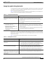
Design Concepts for Using the Switch 1-9
Small to Medium-Sized Network Configuration 1-11
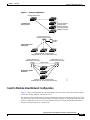
Collapsed Backbone and Switch Cluster Configuration 1-13
Large Campus Configuration 1-14
Multidwelling Network Using Catalyst 2950 Switches 1-15
Long-Distance, High-Bandwidth Transport Configuration 1-17
Where to Go Next
1-18
Catalyst 2950 and Catalyst 2955 Switch Software Configuration Guide
78-11380-07
iii
Contents
CHAPTER
2
Using the Command-Line Interface
IOS Command Modes
Getting Help
2-1
2-1
2-3
Abbreviating Commands
2-4
Using no and default Forms of Commands
Understanding CLI Messages
2-4
2-5
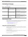
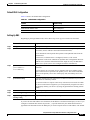
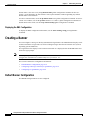
Using Command History 2-5
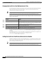
Changing the Command History Buffer Size 2-5
Recalling Commands 2-6
Disabling the Command History Feature 2-6
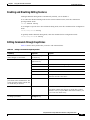
Using Editing Features 2-6
Enabling and Disabling Editing Features 2-7
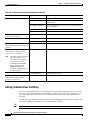
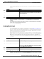
Editing Commands through Keystrokes 2-7
Editing Command Lines that Wrap 2-8
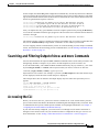
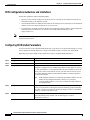
Searching and Filtering Output of show and more Commands
Accessing the CLI
2-9
Accessing the CLI from a Browser
CHAPTER
3
2-9
2-10
Configuring Catalyst 2955 Switch Alarms
3-1
Understanding Catalyst 2955 Switch Alarms
Global Status Monitoring Alarms 3-2
FCS Error Hysteresis Threshold 3-2
Port Status Monitoring Alarms 3-3
Triggering Alarm Options 3-4
3-1
Configuring Catalyst 2955 Switch Alarms 3-4
Default Catalyst 2955 Switch Alarm Configuration 3-5
Configuring the Power Supply Alarm 3-5
Setting the Power Mode 3-5
Setting the Power Supply Alarm Options 3-6
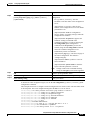
Configuring the Switch Temperature Alarms 3-6
Setting a Secondary Temperature Threshold for the Switch
Associating the Temperature Alarms to a Relay 3-7
Configuring the FCS Bit Error Rate Alarm 3-8
Setting the FCS Error Threshold 3-8
Setting the FCS Error Hysteresis Threshold 3-9
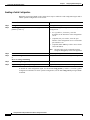
Configuring Alarm Profiles 3-10
Creating or Modifying an Alarm Profile 3-10
Attaching an Alarm Profile to a Specific Port 3-11
3-7
Catalyst 2950 and Catalyst 2955 Switch Software Configuration Guide
iv
78-11380-07
Contents
Enabling SNMP Traps
3-12
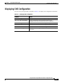
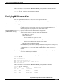
Displaying Catalyst 2955 Switch Alarms Status
CHAPTER
4
Getting Started with CMS
Features
3-12
4-1
4-2
Front Panel View 4-3
Cluster Tree 4-5
Front-Panel Images 4-5
Alarm Relay and Power LEDs on Catalyst 2955 Switches
Redundant Power System LED 4-7
Port Modes and LEDs 4-8
VLAN Membership Modes 4-9
4-7
Topology View 4-10
Topology Icons and Labels 4-12
Device and Link Labels 4-12
Colors in the Topology View 4-13
Topology Display Options 4-14
Menus and Toolbar 4-14
Menu Bar 4-14
Toolbar 4-19
Front Panel View Popup Menus 4-20
Device Popup Menu 4-20
Port Popup Menu 4-21
Topology View Popup Menus 4-21
Link Popup Menu 4-21
Device Popup Menus 4-22
Interaction Modes 4-24
Guide Mode 4-24
Expert Mode 4-25
Wizards 4-25
Tool Tips 4-25
Online Help 4-25
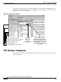
CMS Window Components 4-26
Host Name List 4-27
Tabs, Lists, and Tables 4-28
Filter Editor 4-28
Buttons 4-28
Green Border Around a Field or Cell
Red Border Around a Field 4-29
4-28
Catalyst 2950 and Catalyst 2955 Switch Software Configuration Guide
78-11380-07
v
Contents
Accessing CMS 4-29
Access Modes in CMS 4-30
HTTP Access to CMS 4-31
Saving Your Configuration
4-31
Restoring Your Configuration
CMS Preferences
4-32
4-32
Using Different Versions of CMS
Where to Go Next
CHAPTER
5
4-32
4-33
Assigning the Switch IP Address and Default Gateway
Understanding the Boot Process
5-1
Assigning Switch Information 5-2
Default Switch Information 5-3
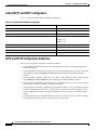
Understanding DHCP-Based Autoconfiguration
DHCP Client Request Process 5-4
Configuring the DHCP Server 5-5
Configuring the TFTP Server 5-5
Configuring the DNS 5-6
Configuring the Relay Device 5-6
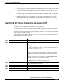
Obtaining Configuration Files 5-7
Example Configuration 5-8
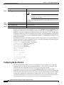
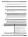
Manually Assigning IP Information 5-10
Checking and Saving the Running Configuration
CHAPTER
6
Configuring IE2100 CNS Agents
5-1
5-3
5-10
6-1
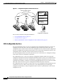
Understanding IE2100 Series Configuration Registrar Software 6-1
CNS Configuration Service 6-2
CNS Event Service 6-3
NameSpace Mapper 6-3
What You Should Know About ConfigID, DeviceID, and Host Name
ConfigID 6-3
DeviceID 6-4
Host Name and DeviceID 6-4
Using Host Name, DeviceID, and ConfigID 6-4
6-3
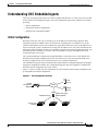
Understanding CNS Embedded Agents 6-5
Initial Configuration 6-5
Incremental (Partial) Configuration 6-6
Synchronized Configuration 6-6
Catalyst 2950 and Catalyst 2955 Switch Software Configuration Guide
vi
78-11380-07
Contents
Configuring CNS Embedded Agents 6-6
Enabling Automated CNS Configuration 6-6
Enabling the CNS Event Agent 6-8
Enabling the CNS Configuration Agent 6-9
Enabling an Initial Configuration 6-9
Enabling a Partial Configuration 6-12
Displaying CNS Configuration
CHAPTER
7
Clustering Switches
6-13
7-1
Understanding Switch Clusters 7-2
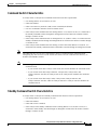
Command Switch Characteristics 7-3
Standby Command Switch Characteristics 7-3
Candidate Switch and Member Switch Characteristics
7-5
Planning a Switch Cluster 7-5
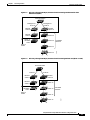
Automatic Discovery of Cluster Candidates and Members 7-6
Discovery through CDP Hops 7-6
Discovery through Non-CDP-Capable and Noncluster-Capable Devices
Discovery through the Same Management VLAN 7-9
Discovery through Different Management VLANs 7-10
Discovery of Newly Installed Switches 7-11
HSRP and Standby Command Switches 7-12
Virtual IP Addresses 7-13
Other Considerations for Cluster Standby Groups 7-14
Automatic Recovery of Cluster Configuration 7-15
IP Addresses 7-16
Host Names 7-17
Passwords 7-17
SNMP Community Strings 7-17
TACACS+ and RADIUS 7-18
Access Modes in CMS 7-18
Management VLAN 7-19
LRE Profiles
7-19
Availability of Switch-Specific Features in Switch Clusters 7-20
7-8
Creating a Switch Cluster 7-20
Enabling a Command Switch 7-20
Adding Member Switches 7-21
Creating a Cluster Standby Group 7-23
Verifying a Switch Cluster 7-26
Catalyst 2950 and Catalyst 2955 Switch Software Configuration Guide
78-11380-07
vii
Contents
Using the CLI to Manage Switch Clusters 7-27
Catalyst 1900 and Catalyst 2820 CLI Considerations
Using SNMP to Manage Switch Clusters
CHAPTER
8
Administering the Switch
7-27
7-28
8-1
Managing the System Time and Date 8-1
Understanding the System Clock 8-1
Understanding Network Time Protocol 8-2
Configuring NTP 8-3
Default NTP Configuration 8-4
Configuring NTP Authentication 8-4
Configuring NTP Associations 8-5
Configuring NTP Broadcast Service 8-6
Configuring NTP Access Restrictions 8-7
Configuring the Source IP Address for NTP Packets 8-9
Displaying the NTP Configuration 8-10
Configuring Time and Date Manually 8-10
Setting the System Clock 8-11
Displaying the Time and Date Configuration 8-11
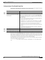
Configuring the Time Zone 8-12
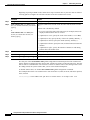
Configuring Summer Time (Daylight Saving Time) 8-13
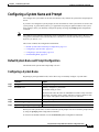
Configuring a System Name and Prompt 8-15
Default System Name and Prompt Configuration
Configuring a System Name 8-15
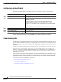
Configuring a System Prompt 8-16
Understanding DNS 8-16
Default DNS Configuration 8-17
Setting Up DNS 8-17
Displaying the DNS Configuration 8-18
Creating a Banner 8-18
Default Banner Configuration 8-18
Configuring a Message-of-the-Day Login Banner
Configuring a Login Banner 8-20
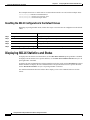
Managing the MAC Address Table 8-20
Building the Address Table 8-21
MAC Addresses and VLANs 8-21
Default MAC Address Table Configuration
Changing the Address Aging Time 8-22
Removing Dynamic Address Entries 8-23
8-15
8-19
8-22
Catalyst 2950 and Catalyst 2955 Switch Software Configuration Guide
viii
78-11380-07
Contents
Configuring MAC Address Notification Traps 8-23
Adding and Removing Static Address Entries 8-25
Adding and Removing Secure Addresses 8-26
Displaying Address Table Entries 8-26
Managing the ARP Table
CHAPTER
9
8-27
Configuring Switch-Based Authentication
9-1
Preventing Unauthorized Access to Your Switch
9-1
Protecting Access to Privileged EXEC Commands 9-2
Default Password and Privilege Level Configuration 9-2
Setting or Changing a Static Enable Password 9-3
Protecting Enable and Enable Secret Passwords with Encryption
Setting a Telnet Password for a Terminal Line 9-5
Configuring Username and Password Pairs 9-6
Configuring Multiple Privilege Levels 9-7
Setting the Privilege Level for a Command 9-7
Changing the Default Privilege Level for Lines 9-8
Logging into and Exiting a Privilege Level 9-9
9-4
Controlling Switch Access with TACACS+ 9-9
Understanding TACACS+ 9-9
TACACS+ Operation 9-11
Configuring TACACS+ 9-11
Default TACACS+ Configuration 9-12
Identifying the TACACS+ Server Host and Setting the Authentication Key 9-12
Configuring TACACS+ Login Authentication 9-13
Configuring TACACS+ Authorization for Privileged EXEC Access and Network Services
Starting TACACS+ Accounting 9-16
Displaying the TACACS+ Configuration 9-16
Controlling Switch Access with RADIUS 9-17
Understanding RADIUS 9-17
RADIUS Operation 9-18
Configuring RADIUS 9-19
Default RADIUS Configuration 9-19
Identifying the RADIUS Server Host 9-19
Configuring RADIUS Login Authentication 9-22
Defining AAA Server Groups 9-24
Configuring RADIUS Authorization for User Privileged Access and Network Services
Starting RADIUS Accounting 9-27
Configuring Settings for All RADIUS Servers 9-28
9-15
9-26
Catalyst 2950 and Catalyst 2955 Switch Software Configuration Guide
78-11380-07
ix
Contents
Configuring the Switch to Use Vendor-Specific RADIUS Attributes 9-28
Configuring the Switch for Vendor-Proprietary RADIUS Server Communication
Displaying the RADIUS Configuration 9-30
Configuring the Switch for Local Authentication and Authorization
Configuring the Switch for Secure Shell 9-31
Understanding SSH 9-32
Cryptographic Software Image Guidelines
Configuring SSH 9-32
CHAPTER
10
Configuring 802.1X Port-Based Authentication
9-29
9-30
9-32
10-1
Understanding 802.1X Port-Based Authentication 10-1
Device Roles 10-2
Authentication Initiation and Message Exchange 10-3
Ports in Authorized and Unauthorized States 10-4
Voice VLAN Ports 10-5
Using 802.1X with Port Security 10-5
Using 802.1X with VLAN Assignment 10-6
Supported Topologies 10-7
Configuring 802.1X Authentication 10-7
Default 802.1X Configuration 10-8
802.1X Configuration Guidelines 10-9
Enabling 802.1X Authentication 10-9
Configuring the Switch-to-RADIUS-Server Communication 10-11
Enabling Periodic Re-Authentication 10-12
Manually Re-Authenticating a Client Connected to a Port 10-13
Changing the Quiet Period 10-13
Changing the Switch-to-Client Retransmission Time 10-14
Setting the Switch-to-Client Frame-Retransmission Number 10-14
Enabling Multiple Hosts 10-15
Resetting the 802.1X Configuration to the Default Values 10-16
Displaying 802.1X Statistics and Status
CHAPTER
11
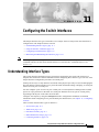
Configuring the Switch Interfaces
10-16
11-1
Understanding Interface Types 11-1
Access Ports 11-2
Trunk Ports 11-2
Port-Based VLANs 11-3
EtherChannel Port Groups 11-3
Connecting Interfaces 11-4
Catalyst 2950 and Catalyst 2955 Switch Software Configuration Guide
x
78-11380-07
Contents
Using the Interface Command 11-4
Procedures for Configuring Interfaces 11-5
Configuring a Range of Interfaces 11-6
Configuring and Using Interface-Range Macros
11-8
Configuring Switch Interfaces 11-9
Default Ethernet Interface Configuration 11-10
Configuring Interface Speed and Duplex Mode 11-11
Configuration Guidelines 11-11
Setting the Interface Speed and Duplex Parameters 11-12
Configuring IEEE 802.3X Flow Control on Gigabit Ethernet Ports 11-13
Adding a Description for an Interface 11-15
Monitoring and Maintaining the Interfaces 11-15
Monitoring Interface and Controller Status 11-15
Clearing and Resetting Interfaces and Counters 11-17
Shutting Down and Restarting the Interface 11-18
CHAPTER
12
Configuring STP
12-1
Understanding Spanning-Tree Features 12-1
STP Overview 12-2
Supported Spanning-Tree Instances 12-2
Bridge Protocol Data Units 12-2
Election of the Root Switch 12-3
Bridge ID, Switch Priority, and Extended System ID
Spanning-Tree Timers 12-5
Creating the Spanning-Tree Topology 12-5
Spanning-Tree Interface States 12-6
Blocking State 12-7
Listening State 12-7
Learning State 12-7
Forwarding State 12-8
Disabled State 12-8
Spanning-Tree Address Management 12-8
STP and IEEE 802.1Q Trunks 12-8
Spanning Tree and Redundant Connectivity 12-9
Accelerated Aging to Retain Connectivity 12-9
12-4
Configuring Spanning-Tree Features 12-10
Default STP Configuration 12-10
STP Configuration Guidelines 12-11
Disabling STP 12-11
Catalyst 2950 and Catalyst 2955 Switch Software Configuration Guide
78-11380-07
xi
Contents
Configuring the Root Switch 12-12
Configuring a Secondary Root Switch 12-14
Configuring the Port Priority 12-15
Configuring the Path Cost 12-16
Configuring the Switch Priority of a VLAN 12-18
Configuring the Hello Time 12-18
Configuring the Forwarding-Delay Time for a VLAN 12-19
Configuring the Maximum-Aging Time for a VLAN 12-20
Configuring STP for Use in a Cascaded Stack 12-20
Displaying the Spanning-Tree Status
CHAPTER
13
Configuring RSTP and MSTP
12-21
13-1
Understanding RSTP 13-2
Spanning-Tree Instances Using RSTP 13-2
Port Roles and the Active Topology 13-2
Rapid Convergence 13-3
Synchronization of Port Roles 13-4
Bridge Protocol Data Unit Format and Processing 13-5
Processing Superior BPDU Information 13-6
Processing Inferior BPDU Information 13-6
Topology Changes 13-6
Understanding MSTP 13-7
Multiple Spanning-Tree Regions 13-7
IST, CIST, and CST 13-8
Operations Within an MST Region
Operations Between MST Regions
Hop Count 13-10
Boundary Ports 13-10
Interoperability with 802.1D STP
13-8
13-9
13-11
Configuring RSTP and MSTP Features 13-11
Default RSTP and MSTP Configuration 13-12
RSTP and MSTP Configuration Guidelines 13-12
Specifying the MST Region Configuration and Enabling MSTP
Configuring the Root Switch 13-14
Configuring a Secondary Root Switch 13-16
Configuring the Port Priority 13-17
Configuring the Path Cost 13-18
Configuring the Switch Priority 13-19
Configuring the Hello Time 13-19
13-13
Catalyst 2950 and Catalyst 2955 Switch Software Configuration Guide
xii
78-11380-07
Contents
Configuring the Forwarding-Delay Time 13-20
Configuring the Maximum-Aging Time 13-21
Configuring the Maximum-Hop Count 13-21
Specifying the Link Type to Ensure Rapid Transitions
Restarting the Protocol Migration Process 13-22
Displaying the MST Configuration and Status
CHAPTER
14
Configuring Optional Spanning-Tree Features
13-22
13-23
14-1
Understanding Optional Spanning-Tree Features 14-1
Understanding Port Fast 14-2
Understanding BPDU Guard 14-3
Understanding BPDU Filtering 14-3
Understanding UplinkFast 14-4
Understanding Cross-Stack UplinkFast 14-5
How CSUF Works 14-6
Events that Cause Fast Convergence 14-7
Limitations 14-8
Connecting the Stack Ports 14-8
Understanding BackboneFast 14-10
Understanding EtherChannel Guard 14-12
Understanding Root Guard 14-12
Understanding Loop Guard 14-13
Configuring Optional Spanning-Tree Features 14-14
Default Optional Spanning-Tree Configuration 14-14
Enabling Port Fast 14-14
Enabling BPDU Guard 14-15
Enabling BPDU Filtering 14-16
Enabling UplinkFast for Use with Redundant Links 14-17
Enabling Cross-Stack UplinkFast 14-18
Enabling BackboneFast 14-19
Enabling EtherChannel Guard 14-19
Enabling Root Guard 14-20
Enabling Loop Guard 14-20
Displaying the Spanning-Tree Status
CHAPTER
15
Configuring VLANs
14-21
15-1
Understanding VLANs 15-1
Supported VLANs 15-2
VLAN Port Membership Modes
15-3
Catalyst 2950 and Catalyst 2955 Switch Software Configuration Guide
78-11380-07
xiii
Contents
Configuring Normal-Range VLANs 15-4
Token Ring VLANs 15-5
Normal-Range VLAN Configuration Guidelines 15-5
VLAN Configuration Mode Options 15-6
VLAN Configuration in config-vlan Mode 15-6
VLAN Configuration in VLAN Configuration Mode
Saving VLAN Configuration 15-7
Default Ethernet VLAN Configuration 15-7
Creating or Modifying an Ethernet VLAN 15-8
Deleting a VLAN 15-10
Assigning Static-Access Ports to a VLAN 15-11
Configuring Extended-Range VLANs 15-12
Default VLAN Configuration 15-12
Extended-Range VLAN Configuration Guidelines
Creating an Extended-Range VLAN 15-13
Displaying VLANs
15-6
15-12
15-14
Configuring VLAN Trunks 15-15
Trunking Overview 15-15
802.1Q Configuration Considerations 15-16
Default Layer 2 Ethernet Interface VLAN Configuration 15-17
Configuring an Ethernet Interface as a Trunk Port 15-17
Interaction with Other Features 15-18
Configuring a Trunk Port 15-18
Defining the Allowed VLANs on a Trunk 15-19
Changing the Pruning-Eligible List 15-20
Configuring the Native VLAN for Untagged Traffic 15-21
Load Sharing Using STP 15-21
Load Sharing Using STP Port Priorities 15-22
Load Sharing Using STP Path Cost 15-23
Configuring VMPS 15-25
Understanding VMPS 15-25
Dynamic Port VLAN Membership 15-26
VMPS Database Configuration File 15-26
Default VMPS Configuration 15-28
VMPS Configuration Guidelines 15-28
Configuring the VMPS Client 15-29
Entering the IP Address of the VMPS 15-29
Configuring Dynamic Access Ports on VMPS Clients
Reconfirming VLAN Memberships 15-30
15-29
Catalyst 2950 and Catalyst 2955 Switch Software Configuration Guide
xiv
78-11380-07
Contents
Changing the Reconfirmation Interval 15-30
Changing the Retry Count 15-31
Monitoring the VMPS 15-31
Troubleshooting Dynamic Port VLAN Membership
VMPS Configuration Example 15-32
CHAPTER
16
Configuring VTP
15-32
16-1
Understanding VTP 16-1
The VTP Domain 16-2
VTP Modes 16-3
VTP Advertisements 16-3
VTP Version 2 16-4
VTP Pruning 16-4
Configuring VTP 16-6
Default VTP Configuration 16-6
VTP Configuration Options 16-7
VTP Configuration in Global Configuration Mode 16-7
VTP Configuration in VLAN Configuration Mode 16-7
VTP Configuration Guidelines 16-8
Domain Names 16-8
Passwords 16-8
Upgrading from Previous Software Releases 16-8
VTP Version 16-9
Configuration Requirements 16-9
Configuring a VTP Server 16-9
Configuring a VTP Client 16-11
Disabling VTP (VTP Transparent Mode) 16-12
Enabling VTP Version 2 16-13
Enabling VTP Pruning 16-14
Adding a VTP Client Switch to a VTP Domain 16-14
Monitoring VTP
CHAPTER
17
16-15
Configuring Voice VLAN
17-1
Understanding Voice VLAN
17-1
Configuring Voice VLAN 17-2
Default Voice VLAN Configuration 17-2
Voice VLAN Configuration Guidelines 17-3
Catalyst 2950 and Catalyst 2955 Switch Software Configuration Guide
78-11380-07
xv
Contents
Configuring a Port to Connect to a Cisco 7960 IP Phone 17-3
Configuring Ports to Carry Voice Traffic in 802.1Q Frames 17-4
Configuring Ports to Carry Voice Traffic in 802.1P Priority-Tagged Frames 17-4
Overriding the CoS Priority of Incoming Data Frames 17-5
Configuring the IP Phone to Trust the CoS Priority of Incoming Data Frames 17-6
Displaying Voice VLAN
CHAPTER
18
17-6
Configuring IGMP Snooping and MVR
18-1
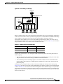
Understanding IGMP Snooping 18-1
Joining a Multicast Group 18-2
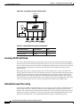
Leaving a Multicast Group 18-4
Immediate-Leave Processing 18-4
Configuring IGMP Snooping 18-5
Default IGMP Snooping Configuration 18-5
Enabling or Disabling IGMP Snooping 18-5
Setting the Snooping Method 18-6
Configuring a Multicast Router Port 18-7
Configuring a Host Statically to Join a Group 18-8
Enabling IGMP Immediate-Leave Processing 18-9
Disabling IP Multicast-Source-Only Learning 18-9
Displaying IGMP Snooping Information
18-10
Understanding Multicast VLAN Registration 18-13
Using MVR in a Multicast Television Application
Configuring MVR 18-15
Default MVR Configuration 18-15
MVR Configuration Guidelines and Limitations
Configuring MVR Global Parameters 18-16
Configuring MVR Interfaces 18-17
Displaying MVR Information
18-13
18-16
18-19
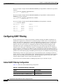
Configuring IGMP Filtering 18-20
Default IGMP Filtering Configuration 18-20
Configuring IGMP Profiles 18-21
Applying IGMP Profiles 18-22
Setting the Maximum Number of IGMP Groups
Displaying IGMP Filtering Configuration
18-23
18-24
Catalyst 2950 and Catalyst 2955 Switch Software Configuration Guide
xvi
78-11380-07
Contents
CHAPTER
19
Configuring Port-Based Traffic Control
Configuring Storm Control 19-1
Understanding Storm Control 19-1
Default Storm Control Configuration
Enabling Storm Control 19-2
Disabling Storm Control 19-3
Configuring Protected Ports
19-1
19-2
19-3
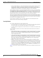
Configuring Port Security 19-4
Understanding Port Security 19-4
Secure MAC Addresses 19-4
Security Violations 19-5
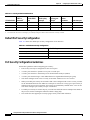
Default Port Security Configuration 19-6
Port Security Configuration Guidelines 19-6
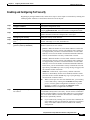
Enabling and Configuring Port Security 19-7
Enabling and Configuring Port Security Aging 19-9
Displaying Port-Based Traffic Control Settings
CHAPTER
20
Configuring UDLD
20-1
Understanding UDLD
20-1
Configuring UDLD 20-3
Default UDLD Configuration 20-3
Enabling UDLD Globally 20-4
Enabling UDLD on an Interface 20-4
Resetting an Interface Shut Down by UDLD
Displaying UDLD Status
CHAPTER
21
Configuring CDP
19-11
20-5
20-6
21-1
Understanding CDP
21-1
Configuring CDP 21-2
Default CDP Configuration 21-2
Configuring the CDP Characteristics 21-2
Disabling and Enabling CDP 21-3
Disabling and Enabling CDP on an Interface
Monitoring and Maintaining CDP
21-4
21-5
Catalyst 2950 and Catalyst 2955 Switch Software Configuration Guide
78-11380-07
xvii
Contents
CHAPTER
22
Configuring SPAN and RSPAN
22-1
Understanding SPAN and RSPAN 22-1
SPAN and RSPAN Concepts and Terminology 22-3
SPAN Session 22-3
Traffic Types 22-3
Source Port 22-4
Destination Port 22-4
Reflector Port 22-4
SPAN Traffic 22-5
SPAN and RSPAN Interaction with Other Features 22-6
SPAN and RSPAN Session Limits 22-6
Default SPAN and RSPAN Configuration 22-7
Configuring SPAN 22-7
SPAN Configuration Guidelines 22-7
Creating a SPAN Session and Specifying Ports to Monitor 22-8
Creating a SPAN Session and Enabling Ingress Traffic 22-9
Removing Ports from a SPAN Session 22-11
Configuring RSPAN 22-12
RSPAN Configuration Guidelines 22-12
Creating an RSPAN Session 22-13
Creating an RSPAN Destination Session 22-14
Removing Ports from an RSPAN Session 22-15
Displaying SPAN and RSPAN Status
CHAPTER
23
Configuring RMON
22-16
23-1
Understanding RMON
23-1
Configuring RMON 23-2
Default RMON Configuration 23-3
Configuring RMON Alarms and Events 23-3
Configuring RMON Collection on an Interface
Displaying RMON Status
CHAPTER
24
23-5
23-6
Configuring System Message Logging
24-1
Understanding System Message Logging
24-1
Configuring System Message Logging 24-2
System Log Message Format 24-2
Default System Message Logging Configuration
Disabling and Enabling Message Logging 24-4
24-3
Catalyst 2950 and Catalyst 2955 Switch Software Configuration Guide
xviii
78-11380-07
Contents
Setting the Message Display Destination Device 24-4
Synchronizing Log Messages 24-6
Enabling and Disabling Timestamps on Log Messages 24-7
Enabling and Disabling Sequence Numbers in Log Messages 24-8
Defining the Message Severity Level 24-8
Limiting Syslog Messages Sent to the History Table and to SNMP 24-10
Configuring UNIX Syslog Servers 24-10
Logging Messages to a UNIX Syslog Daemon 24-11
Configuring the UNIX System Logging Facility 24-11
Displaying the Logging Configuration
CHAPTER
25
Configuring SNMP
24-12
25-1
Understanding SNMP 25-1
SNMP Versions 25-2
SNMP Manager Functions 25-3
SNMP Agent Functions 25-4
SNMP Community Strings 25-4
Using SNMP to Access MIB Variables
SNMP Notifications 25-5
25-4
Configuring SNMP 25-5
Default SNMP Configuration 25-6
SNMP Configuration Guidelines 25-6
Disabling the SNMP Agent 25-7
Configuring Community Strings 25-7
Configuring SNMP Groups and Users 25-9
Configuring SNMP Notifications 25-11
Setting the Agent Contact and Location Information
Limiting TFTP Servers Used Through SNMP 25-14
SNMP Examples 25-15
Displaying SNMP Status
CHAPTER
26
25-14
25-16
Configuring Network Security with ACLs
26-1
Understanding ACLs 26-2
Handling Fragmented and Unfragmented Traffic 26-3
Understanding Access Control Parameters 26-4
Guidelines for Applying ACLs to Physical Interfaces 26-6
Configuring ACLs 26-6
Unsupported Features 26-7
Creating Standard and Extended IP ACLs
26-7
Catalyst 2950 and Catalyst 2955 Switch Software Configuration Guide
78-11380-07
xix
Contents
ACL Numbers 26-8
Creating a Numbered Standard ACL 26-9
Creating a Numbered Extended ACL 26-10
Creating Named Standard and Extended ACLs 26-13
Applying Time Ranges to ACLs 26-15
Including Comments About Entries in ACLs 26-17
Creating Named MAC Extended ACLs 26-18
Creating MAC Access Groups 26-19
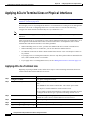
Applying ACLs to Terminal Lines or Physical Interfaces
Applying ACLs to a Terminal Line 26-20
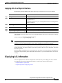
Applying ACLs to a Physical Interface 26-21
26-20
Displaying ACL Information 26-21
Displaying ACLs 26-22
Displaying Access Groups 26-23
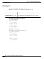
Examples for Compiling ACLs 26-23
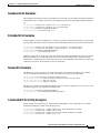
Numbered ACL Examples 26-25
Extended ACL Examples 26-25
Named ACL Example 26-25
Commented IP ACL Entry Examples
CHAPTER
27
Configuring QoS
26-25
27-1
Understanding QoS 27-2
Basic QoS Model 27-4
Classification 27-5
Classification Based on QoS ACLs 27-5
Classification Based on Class Maps and Policy Maps
Policing and Marking 27-7
Mapping Tables 27-8
Queueing and Scheduling 27-8
How Class of Service Works 27-8
Port Priority 27-8
Port Scheduling 27-8
Egress CoS Queues 27-9
27-6
Configuring Auto-QoS 27-9
Generated Auto-QoS Configuration 27-10
Effects of Auto-QoS on the Configuration 27-12
Configuration Guidelines 27-12
Enabling Auto-QoS for VoIP 27-12
Displaying Auto-QoS Information
27-13
Catalyst 2950 and Catalyst 2955 Switch Software Configuration Guide
xx
78-11380-07
Contents
Auto-QoS Configuration Example
27-14
Configuring Standard QoS 27-15
Default Standard QoS Configuration 27-16
Configuration Guidelines 27-17
Configuring Classification Using Port Trust States 27-17
Configuring the Trust State on Ports within the QoS Domain 27-18
Configuring the CoS Value for an Interface 27-20
Configuring Trusted Boundary 27-20
Enabling Pass-Through Mode 27-22
Configuring a QoS Policy 27-23
Classifying Traffic by Using ACLs 27-24
Classifying Traffic by Using Class Maps 27-27
Classifying, Policing, and Marking Traffic by Using Policy Maps 27-28
Configuring CoS Maps 27-31
Configuring the CoS-to-DSCP Map 27-32
Configuring the DSCP-to-CoS Map 27-33
Configuring the Egress Queues 27-34
Configuring CoS Priority Queues 27-34
Configuring WRR Priority 27-35
Enabling the Expedite Queue and Configuring WRR Priority 27-35
Displaying Standard QoS Information
27-36
Standard QoS Configuration Examples 27-36
QoS Configuration for the Existing Wiring Closet 27-37
QoS Configuration for the Intelligent Wiring Closet 27-38
CHAPTER
28
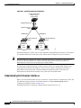
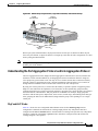
Configuring EtherChannels
28-1
Understanding EtherChannels 28-1
Understanding Port-Channel Interfaces 28-2
Understanding the Port Aggregation Protocol and Link Aggregation Protocol
PAgP and LACP Modes 28-3
Physical Learners and Aggregate-Port Learners 28-5
PAgP and LACP Interaction with Other Features 28-5
Understanding Load Balancing and Forwarding Methods 28-6
28-3
Configuring EtherChannels 28-7
Default EtherChannel Configuration 28-8
EtherChannel Configuration Guidelines 28-8
Configuring Layer 2 EtherChannels 28-9
Configuring EtherChannel Load Balancing 28-11
Configuring the PAgP Learn Method and Priority 28-12
Catalyst 2950 and Catalyst 2955 Switch Software Configuration Guide
78-11380-07
xxi
Contents
Configuring the LACP Port Priority 28-12
Configuring Hot Standby Ports 28-13
Configuring the LACP System Priority 28-13
Displaying EtherChannel, PAgP, and LACP Status
CHAPTER
29
Troubleshooting
28-15
29-1
Using Recovery Procedures 29-1
Recovering from Corrupted Software 29-2
Recovering from a Lost or Forgotten Password 29-2
Recovering from a Lost or Forgotten Password on the Catalyst 2955 Switch
Recovering from a Command Switch Failure 29-6
Replacing a Failed Command Switch with a Cluster Member 29-7
Replacing a Failed Command Switch with Another Switch 29-8
Recovering from Lost Member Connectivity 29-10
Preventing Autonegotiation Mismatches
29-10
GBIC Module Security and Identification
29-10
29-4
Diagnosing Connectivity Problems 29-11
Using Ping 29-11
Understanding Ping 29-11
Executing Ping 29-11
Using Layer 2 Traceroute 29-12
Understanding Layer 2 Traceroute 29-12
Switches Supporting Layer 2 Traceroute 29-13
Usage Guidelines 29-13
Displaying the Physical Path 29-14
Using Debug Commands 29-14
Enabling Debugging on a Specific Feature 29-15
Enabling All-System Diagnostics 29-15
Redirecting Debug and Error Message Output 29-15
Using the debug autoqos Command 29-16
Using the crashinfo File
APPENDIX
A
Supported MIBs
MIB List
29-17
A-1
A-1
Using FTP to Access the MIB Files
A-3
INDEX
Catalyst 2950 and Catalyst 2955 Switch Software Configuration Guide
xxii
78-11380-07
Preface
Audience
The Catalyst 2950 and Catalyst 2955 Switch Software Configuration Guide is for the network manager
responsible for configuring the Catalyst 2950 and the Catalyst 2955 switches, hereafter referred to as the
switches. Before using this guide, you should be familiar with the concepts and terminology of Ethernet
and local area networking.
Purpose
This guide provides information about configuring and troubleshooting a switch or switch clusters. It
includes descriptions of the management interface options and the features supported by the switch
software. The Catalyst 2950 switch is supported by either the standard software image (SI) or the enhanced
software image (EI). The Catalyst 2955 switch is supported only by the EI.
The EI provides a richer set of features, including access control lists (ACLs), enhanced quality of service
(QoS) features, extended-range VLANs, the IEEE 802.1W Rapid Spanning Tree Protocol (RSTP), and the
IEEE 802.1S Multiple STP (MSTP), and Remote Switched Port Analyzer (RSPAN). For a list of switches
that support the SI and the EI, see Table 1-1 in Chapter 1, “Overview.”
Use this guide with other documents for information about these topics:
•
Requirements—This guide assumes that you have met the hardware and software requirements and
cluster compatibility requirements described in the release notes.
•
Start-up information—This guide assumes that you have assigned switch IP information and
passwords by using the setup program described in the release notes.
•
Cluster Management Suite (CMS) information—This guide provides an overview of the CMS
web-based, switch management interface. For information about CMS requirements and the
procedures for browser and plug-in configuration and accessing CMS, refer to the release notes. For
CMS field-level window descriptions and procedures, refer to the CMS online help.
•
Cluster configuration—This guide provides information about planning for, creating, and
maintaining switch clusters. Because configuring switch clusters is most easily performed through
CMS, this guide does not provide the command-line interface (CLI) procedures. For the cluster
commands, refer to the command reference for this release.
•
CLI command information—This guide provides an overview for using the CLI. For complete
syntax and usage information about the commands that have been specifically created or changed
for the switches, refer to the command reference for this release.
Catalyst 2950 and Catalyst 2955 Switch Software Configuration Guide
78-11380-07
xxiii
Preface
Conventions
This guide does not describe system messages you might encounter or how to install your switch. For
more information, refer to the Catalyst 2950 and Catalyst 2955 Desktop Switch System Message Guide
for this release, to the Catalyst 2950 Desktop Switch Hardware Installation Guide, and to the
Catalyst 2955 Switch Hardware Installation Guide.
Note
This guide does not repeat the concepts and CLI procedures provided in the standard Cisco IOS
Release 12.1 documentation. For information about the standard IOS Release 12.1 commands, refer to
the IOS documentation set available from the Cisco.com home page at Service and Support >
Technical Documents. On the Cisco Product Documentation home page, select Release 12.1 from the Cisco
IOS Software drop-down list.
Note
This software release does not support the Catalyst 2950 LRE switches. For information about these
switches, refer to the Catalyst 2950 LRE switch release notes.
Conventions
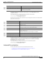
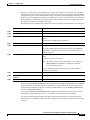
This guide uses these conventions to convey instructions and information:
Command descriptions use these conventions:
•
Commands and keywords are in boldface text.
•
Arguments for which you supply values are in italic.
•
Square brackets ([ ]) indicate optional elements.
•
Braces ({ }) group required choices, and vertical bars ( | ) separate the alternative elements.
•
Braces and vertical bars within square brackets ([{ | }]) indicate a required choice within an optional
element.
Interactive examples use these conventions:
•
Terminal sessions and system displays are in screen font.
•
Information you enter is in boldface
•
Nonprinting characters, such as passwords or tabs, are in angle brackets (< >).
screen
font.
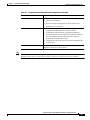
Notes, cautions, and tips use these conventions and symbols:
Note
Caution
Tip
Means reader take note. Notes contain helpful suggestions or references to materials not contained in
this manual.
Means reader be careful. In this situation, you might do something that could result in equipment
damage or loss of data.
Means the following will help you solve a problem. The tips information might not be troubleshooting
or even an action, but could be useful information.
Catalyst 2950 and Catalyst 2955 Switch Software Configuration Guide
xxiv
78-11380-07
Preface
Related Publications
Related Publications
These documents provide complete information about the switch and are available from this URL:
http://www.cisco.com/univercd/cc/td/doc/product/lan/cat2950/index.htm
You can order printed copies of documents with a DOC-xxxxxx= number from the Cisco.com sites and
from the telephone numbers listed in the “Obtaining Documentation” section on page xxvi.
•
Note
Release Notes for the Catalyst 2950 and Catalyst 2955 Switch (not orderable but available on
Cisco.com)
Switch requirements and procedures for initial configurations and software upgrades tend to change and
therefore appear only in the release notes. Before installing, configuring, or upgrading the switch, refer
to the release notes on Cisco.com for the latest information.
For hardware information for the Catalyst 2950 and Catalyst 2955 switches, refer to these documents:
•
Catalyst 2950 Desktop Switch Hardware Installation Guide (order number DOC-7811157=)
•
Catalyst 2955 Hardware Installation Guide (order number DOC-7814944=)
For software information about Release 12.1(13)EA1 or later for the Catalyst 2950 and Catalyst 2955
switches, refer to these documents:
•
Catalyst 2950 and Catalyst 2955 Desktop Switch Software Configuration Guide (order number
DOC-7811380=)
•
Catalyst 2950 and Catalyst 2955 Desktop Switch Command Reference (order number
DOC-7811381=)
•
Catalyst 2950 and Catalyst 2955 Desktop Switch System Message Guide (order number
DOC-7814233=)
For software information about Release 12.1(12c)EA1 for the Catalyst 2950 and Catalyst 2955
switches, refer to these documents:
•
Catalyst 2950 and Catalyst 2955 Switch Software Configuration Guide (order number
DOC-7815303=)
•
Catalyst 2950 and Catalyst 2955 Switch Command Reference (order number DOC-7815304=)
•
Catalyst 2950 and Catalyst 2955 Switch System Message Guide (order number DOC-7815306=)
Note
The Catalyst 2955 switches are not supported by software releases earlier than
Release 12.1(12c)EA1.
For information about the Catalyst 2950 LRE switches, refer to these documents:
•
Catalyst 2950 Desktop Switch Software Configuration Guide (order number DOC-7814982=)
•
Catalyst 2950 Desktop Switch Command Reference (order number DOC-7814984=)
•
Catalyst 2950 Desktop Switch System Message Guide (order number DOC-7814981=)
•
Release Notes for the Catalyst 2950 LRE Switch (not orderable but available on Cisco.com)
Catalyst 2950 and Catalyst 2955 Switch Software Configuration Guide
78-11380-07
xxv
Preface
Obtaining Documentation
For other information about related products, refer to these documents:
•
Catalyst GigaStack Gigabit Interface Converter Hardware Installation Guide
(order number DOC-786460=)
•
Cluster Management Suite (CMS) online help (available only from the switch CMS software)
•
CWDM Passive Optical System Installation Note (not orderable but is available on Cisco.com)
•
1000BASE-T Gigabit Interface Converter Installation Notes (not orderable but is available on
Cisco.com)
Obtaining Documentation
Cisco provides several ways to obtain documentation, technical assistance, and other technical
resources. These sections explain how to obtain technical information from Cisco Systems.
World Wide Web
You can access the most current Cisco documentation on the World Wide Web at this URL:
http://www.cisco.com/univercd/home/home.htm
You can access the Cisco website at this URL:
http://www.cisco.com
International Cisco web sites can be accessed from this URL:
http://www.cisco.com/public/countries_languages.shtml
Documentation CD-ROM
Cisco documentation and additional literature are available in a Cisco Documentation CD-ROM
package, which may have shipped with your product. The Documentation CD-ROM is updated monthly
and may be more current than printed documentation. The CD-ROM package is available as a single unit
or through an annual subscription.
Registered Cisco.com users can order the Documentation CD-ROM (product number
DOC-CONDOCCD=) through the online Subscription Store:
http://www.cisco.com/go/subscription
Catalyst 2950 and Catalyst 2955 Switch Software Configuration Guide
xxvi
78-11380-07
Preface
Obtaining Technical Assistance
Ordering Documentation
You can find instructions for ordering documentation at this URL:
http://www.cisco.com/univercd/cc/td/doc/es_inpck/pdi.htm
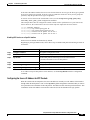
You can order Cisco documentation in these ways:
•
Registered Cisco.com users (Cisco direct customers) can order Cisco product documentation from
the Networking Products MarketPlace:
http://www.cisco.com/en/US/partner/ordering/index.shtml
•
Registered Cisco.com users can order the Documentation CD-ROM (Customer Order Number
DOC-CONDOCCD=) through the online Subscription Store:
http://www.cisco.com/go/subscription
•
Nonregistered Cisco.com users can order documentation through a local account representative by
calling Cisco Systems Corporate Headquarters (California, U.S.A.) at 408 526-7208 or, elsewhere
in North America, by calling 800 553-NETS (6387).
Documentation Feedback
You can submit comments electronically on Cisco.com. On the Cisco Documentation home page, click
Feedback at the top of the page.
You can e-mail your comments to [email protected].
You can submit your comments by mail by using the response card behind the front cover of your
document or by writing to the following address:
Cisco Systems
Attn: Customer Document Ordering
170 West Tasman Drive
San Jose, CA 95134-9883
We appreciate your comments.
Obtaining Technical Assistance
Cisco provides Cisco.com, which includes the Cisco Technical Assistance Center (TAC) Website, as a
starting point for all technical assistance. Customers and partners can obtain online documentation,
troubleshooting tips, and sample configurations from the Cisco TAC website. Cisco.com registered users
have complete access to the technical support resources on the Cisco TAC website, including TAC tools
and utilities.
Catalyst 2950 and Catalyst 2955 Switch Software Configuration Guide
78-11380-07
xxvii
Preface
Obtaining Technical Assistance
Cisco.com
Cisco.com offers a suite of interactive, networked services that let you access Cisco information,
networking solutions, services, programs, and resources at any time, from anywhere in the world.
Cisco.com provides a broad range of features and services to help you with these tasks:
•
Streamline business processes and improve productivity
•
Resolve technical issues with online support
•
Download and test software packages
•
Order Cisco learning materials and merchandise
•
Register for online skill assessment, training, and certification programs
To obtain customized information and service, you can self-register on Cisco.com at this URL:
http://www.cisco.com
Technical Assistance Center
The Cisco TAC is available to all customers who need technical assistance with a Cisco product,
technology, or solution. Two levels of support are available: the Cisco TAC website and the Cisco TAC
Escalation Center. The avenue of support that you choose depends on the priority of the problem and the
conditions stated in service contracts, when applicable.
We categorize Cisco TAC inquiries according to urgency:
•
Priority level 4 (P4)—You need information or assistance concerning Cisco product capabilities,
product installation, or basic product configuration.
•
Priority level 3 (P3)—Your network performance is degraded. Network functionality is noticeably
impaired, but most business operations continue.
•
Priority level 2 (P2)—Your production network is severely degraded, affecting significant aspects
of business operations. No workaround is available.
•
Priority level 1 (P1)—Your production network is down, and a critical impact to business operations
will occur if service is not restored quickly. No workaround is available.
Cisco TAC Website
You can use the Cisco TAC website to resolve P3 and P4 issues yourself, saving both cost and time. The
site provides around-the-clock access to online tools, knowledge bases, and software. To access the
Cisco TAC website, go to this URL:
http://www.cisco.com/tac
All customers, partners, and resellers who have a valid Cisco service contract have complete access to
the technical support resources on the Cisco TAC website. Some services on the Cisco TAC website
require a Cisco.com login ID and password. If you have a valid service contract but do not have a login
ID or password, go to this URL to register:
http://tools.cisco.com/RPF/register/register.do
Catalyst 2950 and Catalyst 2955 Switch Software Configuration Guide
xxviii
78-11380-07
Preface
Obtaining Additional Publications and Information
If you are a Cisco.com registered user, and you cannot resolve your technical issues by using the Cisco
TAC website, you can open a case online at this URL:
http://www.cisco.com/en/US/support/index.html
If you have Internet access, we recommend that you open P3 and P4 cases through the Cisco TAC
website so that you can describe the situation in your own words and attach any necessary files.
Cisco TAC Escalation Center
The Cisco TAC Escalation Center addresses priority level 1 or priority level 2 issues. These
classifications are assigned when severe network degradation significantly impacts business operations.
When you contact the TAC Escalation Center with a P1 or P2 problem, a Cisco TAC engineer
automatically opens a case.
To obtain a directory of toll-free Cisco TAC telephone numbers for your country, go to this URL:
http://www.cisco.com/warp/public/687/Directory/DirTAC.shtml
Before calling, please check with your network operations center to determine the level of Cisco support
services to which your company is entitled: for example, SMARTnet, SMARTnet Onsite, or Network
Supported Accounts (NSA). When you call the center, please have available your service agreement
number and your product serial number.
Obtaining Additional Publications and Information
Information about Cisco products, technologies, and network solutions is available from various online
and printed sources.
•
The Cisco Product Catalog describes the networking products offered by Cisco Systems as well as
ordering and customer support services. Access the Cisco Product Catalog at this URL:
http://www.cisco.com/en/US/products/products_catalog_links_launch.html
•
Cisco Press publishes a wide range of networking publications. Cisco suggests these titles for new
and experienced users: Internetworking Terms and Acronyms Dictionary, Internetworking
Technology Handbook, Internetworking Troubleshooting Guide, and the Internetworking Design
Guide. For current Cisco Press titles and other information, go to Cisco Press online at this URL:
http://www.ciscopress.com
•
Packet magazine is the Cisco monthly periodical that provides industry professionals with the latest
information about the field of networking. You can access Packet magazine at this URL:
http://www.cisco.com/en/US/about/ac123/ac114/about_cisco_packet_magazine.html
•
iQ Magazine is the Cisco monthly periodical that provides business leaders and decision makers
with the latest information about the networking industry. You can access iQ Magazine at this URL:
http://business.cisco.com/prod/tree.taf%3fasset_id=44699&public_view=true&kbns=1.html
•
Internet Protocol Journal is a quarterly journal published by Cisco Systems for engineering
professionals involved in the design, development, and operation of public and private internets and
intranets. You can access the Internet Protocol Journal at this URL:
http://www.cisco.com/en/US/about/ac123/ac147/about_cisco_the_internet_protocol_journal.html
•
Training—Cisco offers world-class networking training, with current offerings in network training
listed at this URL:
http://www.cisco.com/en/US/learning/le31/learning_recommended_training_list.html
Catalyst 2950 and Catalyst 2955 Switch Software Configuration Guide
78-11380-07
xxix
Preface
Obtaining Additional Publications and Information
Catalyst 2950 and Catalyst 2955 Switch Software Configuration Guide
xxx
78-11380-07
C H A P T E R
1
Overview
This guide provides information about configuring and troubleshooting Catalyst 2950 and Catalyst 2955
switches.
The Catalyst 2955 switch supports all the features in the enhanced software image (EI) for the
Catalyst 2950 switch (refer to the switch command reference for more details). The Catalyst 2955 switch
also supports an additional set of features that are described in Chapter 3, “Configuring Catalyst 2955
Switch Alarms.” The Catalyst 2955 switch has facilities to process alarms related to the temperature,
power supply conditions, and status of the Ethernet ports.
This chapter provides these topics about the Catalyst 2950 and Catalyst 2955 switch software:
•
Features, page 1-1
•
Management Options, page 1-7
•
Network Configuration Examples, page 1-8
•
Where to Go Next, page 1-18
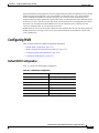
Features
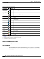
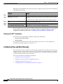
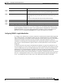
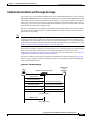
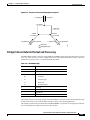
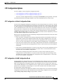
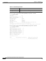
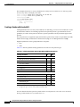
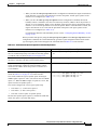
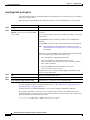
The Catalyst 2950 and Catalyst 2955 software supports the switches listed in Table 1-1 and in the release
notes.
Table 1-1
Switches Supported
Switch
Software
Image
Catalyst 2950-12
SI1
Catalyst 2950-24
SI
Catalyst 2950C-24
EI
Catalyst 2950G-12-EI
EI
Catalyst 2950G-24-EI
EI
Catalyst 2950G-24-EI-DC
EI
Catalyst 2950G-48-EI
EI
Catalyst 2950SX-24
SI
Catalyst 2950T-24
EI
Catalyst 2955C-12
EI
Catalyst 2950 and Catalyst 2955 Switch Software Configuration Guide
78-11380-07
1-1
Chapter 1
Overview
Features
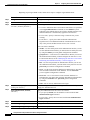
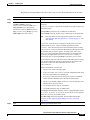
Table 1-1
Switches Supported (continued)
Switch
Software
Image
Catalyst 2955S-12
EI
Catalyst 2955T-12
EI
1. SI = standard software image
Note
This software release does not support the Catalyst 2950 LRE switches. For information about these
switches, refer to documentation for the Catalyst 2950 LRE switches.
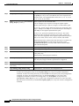
This section describes the features supported in this release:
Note
Some features require that you have the EI installed on your switch. For a list of the switches that support
the EI, see Table 1-1, or refer to the release notes for this release.
Ease of Use and Ease of Deployment
•
Cluster Management Suite (CMS) software for simplifying switch and switch cluster management
through a web browser, such as Netscape Communicator or Microsoft Internet Explorer, from
anywhere in your intranet
•
Switch clustering technology used with CMS for
– Unified configuration, monitoring, authentication, and software upgrade of multiple switches
(refer to the release notes for a list of eligible cluster members).
– Automatic discovery of candidate switches and creation of clusters of up to 16 switches that can
be managed through a single IP address.
– Extended discovery of cluster candidates that are not directly connected to the command switch.
•
Note
Hot Standby Router Protocol (HSRP) for command-switch redundancy. The redundant command
switches used for HSRP must have compatible software releases.
See the “Advantages of Using CMS and Clustering Switches” section on page 1-8. Refer to the
release notes for the CMS, cluster hardware, software, and browser requirements.
Performance
•
Autosensing of speed on the 10/100 and 10/100/1000 ports and autonegotiation of duplex mode on
the 10/100 ports for optimizing bandwidth
•
IEEE 802.3X flow control on Gigabit Ethernet ports operating in full-duplex mode
•
Fast EtherChannel and Gigabit EtherChannel for enhanced fault tolerance and for providing up
to 2 Gbps of bandwidth between switches, routers, and servers
•
Support for frames larger than 1500 bytes. The Catalyst 2950G-12-EI, 2950G-24-EI, 2950G-24-EI-DC,
and 2950G-48-EI switches running Cisco IOS Release 12.1(6)EA2 or later support frame sizes from
1500 to 1530 bytes. The Catalyst 2955C-12, 2955S-12, and 2955T-12 switches running
Release 12.1(12c)EA1 or later also support frame sizes from 1500 to 1530 bytes.
Catalyst 2950 and Catalyst 2955 Switch Software Configuration Guide
1-2
78-11380-07
Chapter 1
Overview
Features
•
Per-port broadcast storm control for preventing faulty end stations from degrading overall system
performance with broadcast storms
•
Port Aggregation Protocol (PAgP) and Link Aggregation Control Protocol (LACP) for automatic
creation of EtherChannel links
•
Internet Group Management Protocol (IGMP) snooping support to limit flooding of IP multicast
traffic
•
Multicast VLAN registration (MVR) to continuously send multicast streams in a multicast VLAN
while isolating the streams from subscriber VLANs for bandwidth and security reasons
•
IGMP filtering for controlling the set of multicast groups to which hosts on a switch port can belong
•
Protected port (private VLAN edge port) option for restricting the forwarding of traffic to designated
ports on the same switch
•
Dynamic address learning for enhanced security
Manageability
•
Cisco Intelligence Engine 2100 (IE2100) Series Cisco Networking Services (CNS) embedded
agents for automating switch management, configuration storage and delivery (available only with
the EI)
•
Dynamic Host Configuration Protocol (DHCP)-based autoconfiguration for automatically
configuring the switch during startup with IP address information and a configuration file that it
receives during DHCP-based autoconfiguration
Note
DHCP replaces the Bootstrap Protocol (BOOTP) feature autoconfiguration to ensure retrieval of
configuration files by unicast TFTP messages. BOOTP is available in earlier software releases
for this switch.
•
Address Resolution Protocol (ARP) for identifying a switch through its IP address and its
corresponding MAC address
•
Cisco Discovery Protocol (CDP) versions 1 and 2 for network topology discovery and mapping
between the switch and other Cisco devices on the network
•
Network Time Protocol (NTP) for providing a consistent timestamp to all switches from an external
source
•
Directed unicast requests to a Trivial File Transfer Protocol (TFTP) server for obtaining software
upgrades from a TFTP server
•
Default configuration storage in Flash memory to ensure that the switch can be connected to a
network and can forward traffic with minimal user intervention
•
In-band management access through a CMS web-based session
•
In-band management access through up to 16 simultaneous Telnet connections for multiple
command-line interface (CLI)-based sessions over the network
•
In-band management access through up to 5 simultaneous, encrypted Secure Shell (SSH)
connections for multiple CLI-based sessions over the network (only available in the enhanced
cryptographic software image)
•
In-band management access through Simple Network Management Protocol (SNMP) versions 1, 2c,
and 3 get and set requests
•
Out-of-band management access through the switch console port to a directly-attached terminal or
to a remote terminal through a serial connection and a modem
Catalyst 2950 and Catalyst 2955 Switch Software Configuration Guide
78-11380-07
1-3
Chapter 1
Overview
Features
Note
For additional descriptions of the management interfaces, see the “Management Options”
section on page 1-7.
Redundancy
•
HSRP for command-switch redundancy
•
UniDirectional link detection (UDLD) on all Ethernet ports for detecting and disabling
unidirectional links on fiber-optic interfaces caused by incorrect fiber-optic wiring or port faults
•
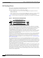
IEEE 802.1D Spanning Tree Protocol (STP) for redundant backbone connections and loop-free
networks. STP has these features:
– Per-VLAN Spanning Tree (PVST) for balancing load across VLANs
– Per-VLAN Rapid Spanning Tree (PVRST) for balancing load across VLANs (available only
with the EI)
– UplinkFast, cross-stack UplinkFast, and BackboneFast for fast convergence after a
spanning-tree topology change and for achieving load balancing between redundant uplinks,
including Gigabit uplinks and cross-stack Gigabit uplinks
•
IEEE 802.1S Multiple STP (MSTP) for grouping VLANs into a spanning-tree instance, and
providing for multiple forwarding paths for data traffic and load balancing (available only with
the EI)
•
IEEE 802.1W Rapid STP (RSTP) for rapid convergence of the spanning tree by immediately
transitioning root and designated ports to the forwarding state (available only with the EI)
•
Optional spanning-tree features available in the PVST, PVRST, and MSTP modes:
– Port Fast for eliminating the forwarding delay by enabling a port to immediately transition from
the blocking state to the forwarding state
– BPDU guard for shutting down Port Fast-enabled ports that receive BPDUs
– BPDU filtering for preventing a Port Fast-enabled port from sending or receiving BPDUs
– Root guard for preventing switches outside the network core from becoming the spanning-tree
root
– Loop guard for preventing alternate or root ports from becoming designated ports because of a
failure that leads to a unidirectional link
Note
The switch supports up to 64 spanning-tree instances.
VLAN Support
•
The switches support 250 port-based VLANs for assigning users to VLANs associated with
appropriate network resources, traffic patterns, and bandwidth
Note
The Catalyst 2950-12, Catalyst 2950-24, and Catalyst 2950SX-24 switches support only 64
port-based VLANs.
•
The switch supports up to 4094 VLAN IDs to allow service provider networks to support the number of
VLANs allowed by the IEEE 802.1Q standard (available only with the EI)
Catalyst 2950 and Catalyst 2955 Switch Software Configuration Guide
1-4
78-11380-07
Chapter 1
Overview
Features
•
IEEE 802.1Q trunking protocol on all ports for network moves, adds, and changes; management and
control of broadcast and multicast traffic; and network security by establishing VLAN groups for
high-security users and network resources
•
VLAN Membership Policy Server (VMPS) for dynamic VLAN membership
•
VLAN Trunking Protocol (VTP) pruning for reducing network traffic by restricting flooded traffic
to links destined for stations receiving the traffic
•
Dynamic Trunking Protocol (DTP) for negotiating trunking on a link between two devices and for
negotiating the type of trunking encapsulation (802.1Q) to be used
•
Voice VLAN for creating subnets for voice traffic from Cisco IP Phones
Security
•
Bridge protocol data unit (BPDU) guard for shutting down a Port Fast-configured port when an
invalid configuration occurs
•
Protected port option for restricting the forwarding of traffic to designated ports on the same switch
•
Password-protected access (read-only and read-write access) to management interfaces (CMS and
CLI) for protection against unauthorized configuration changes
•
Port security option for limiting and identifying MAC addresses of the stations allowed to access
the port
•
Port security aging to set the aging time for secure addresses on a port
•
Multilevel security for a choice of security level, notification, and resulting actions
•
MAC-based port-level security for restricting the use of a switch port to a specific group of source
addresses and preventing switch access from unauthorized stations (available only with the EI)
•
Terminal Access Controller Access Control System Plus (TACACS+), a proprietary feature for
managing network security through a TACACS server
•
IEEE 802.1X port-based authentication to prevent unauthorized devices from gaining access to the
network
•
IEEE 802.1X port-based authentication with VLAN assignment for restricting
802.1X-authenticated users to a specified VLAN (available only with the EI)
•
IEEE 802.1X port-based authentication with port security for authenticating the port and managing
network access for all MAC addresses, including that of the client (available only with the EI)
•
IEEE 802.1X port-based authentication with port security for controlling access to 802.1X
multiple-host ports
•
IEEE 802.1X port-based authentication with voice VLAN to permit an IP phone access to the voice
VLAN irrespective of the authorized or unauthorized state of the port
•
Standard and extended IP access control lists (ACLs) for defining security policies (available only
with the EI)
Catalyst 2950 and Catalyst 2955 Switch Software Configuration Guide
78-11380-07
1-5
Chapter 1
Overview
Features
Quality of Service and Class of Service
•
Automatic QoS (auto-QoS) to simplify the deployment of existing QoS features by classifying
traffic and configuring egress queues (voice over IP only) (only available in the EI)
•
Classification
– IP Differentiated Services Code Point (IP DSCP) and class of service (CoS) marking priorities
on a per-port basis for protecting the performance of mission-critical applications (only
available with the EI)
– Flow-based packet classification (classification based on information in the MAC, IP, and
TCP/UDP headers) for high-performance quality of service at the network edge, allowing for
differentiated service levels for different types of network traffic and for prioritizing
mission-critical traffic in the network (only available in the EI)
– Support for IEEE 802.1P CoS scheduling for classification and preferential treatment of
high-priority voice traffic
– Trusted boundary (detect the presence of a Cisco IP Phone, trust the CoS value received, and
ensure port security. If the IP phone is not detected, disable the trusted setting on the port and
prevent misuse of a high-priority queue.)
•
Policing
– Traffic-policing policies on the switch port for allocating the amount of the port bandwidth to
a specific traffic flow
– Policing traffic flows to restrict specific applications or traffic flows to metered, predefined
rates
– Up to 60 policers on ingress Gigabit-capable Ethernet ports
Up to six policers on ingress 10/100 ports
Granularity of 1 Mbps on 10/100 ports and 8 Mbps on 10/100/1000 ports
– Out-of-profile markdown for packets that exceed bandwidth utilization limits
Note
•
Policing is available only in the EI.
Egress Policing and Scheduling of Egress Queues—Four egress queues on all switch ports. Support
for strict priority and weighted round-robin (WRR) CoS policies
Monitoring
•
Switch LEDs that provide visual port and switch status
•
Switched Port Analyzer (SPAN) and Remote SPAN (RSPAN) for traffic monitoring on any port or
VLAN
Note
RSPAN is available only in the EI.
•
SPAN support of Intrusion Detection Systems (IDSs) to monitor, repel, and report network security
violations
•
Four groups (history, statistics, alarms, and events) of embedded remote monitoring (RMON) agents
for network monitoring and traffic analysis
•
MAC address notification for tracking the MAC addresses that the switch has learned or removed
Catalyst 2950 and Catalyst 2955 Switch Software Configuration Guide
1-6
78-11380-07
Chapter 1
Overview
Management Options
•
Syslog facility for logging system messages about authentication or authorization errors, resource
issues, and time-out events
•
Layer 2 traceroute to identify the physical path that a packet takes from a source device to a
destination device
•
Facilities for processing alarms related to temperature, power-supply conditions, and the status of
the Ethernet ports (available only on the Catalyst 2955 switch)
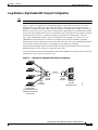
Management Options
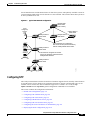
The switches are designed for plug-and-play operation: you only need to assign basic IP information to
the switch and connect it to the other devices in your network. If you have specific network needs, you
can configure and monitor the switch—on an individual basis or as part of a switch cluster—through its
various management interfaces.
This section discusses these topics:
•
Management Interface Options, page 1-7
•
Advantages of Using CMS and Clustering Switches, page 1-8
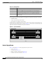
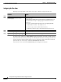
Management Interface Options
You can configure and monitor individual switches and switch clusters by using these interfaces:
•
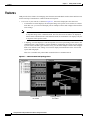
CMS—CMS is a graphical user interface that can be launched from anywhere in your network
through a web browser such as Netscape Communicator or Microsoft Internet Explorer. CMS is
already installed on the switch. Using CMS, you can configure and monitor a standalone switch, a
specific cluster member, or an entire switch cluster. You can also display network topologies to
gather link information and display switch images to modify switch and port level settings.
For more information about CMS, see Chapter 4, “Getting Started with CMS.”
•
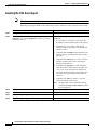
CLI—The switch IOS CLI software is enhanced to support desktop-switching features. You can
configure and monitor the switch and switch cluster members from the CLI. You can access the CLI
either by connecting your management station directly to the switch console port or by using Telnet
or SSH from a remote management station.
For more information about the CLI, see Chapter 2, “Using the Command-Line Interface.”
•
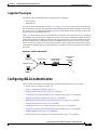
IE2100—Cisco Intelligence Engine 2100 Series Configuration Registrar is a network management
device that works with embedded CNS Agents in the switch software. You can automate initial
configurations and configuration updates by generating switch-specific configuration changes,
sending them to the switch, executing the configuration change, and logging the results.
For more information about IE2100, see Chapter 6, “Configuring IE2100 CNS Agents.”
•
SNMP—SNMP provides a means to monitor and control the switch and switch cluster members.
You can manage switch configuration settings, performance, and security and collect statistics by
using SNMP management applications such as CiscoWorks2000 LAN Management Suite (LMS)
and HP OpenView.
You can manage the switch from an SNMP-compatible management station that is running
platforms such as HP OpenView or SunNet Manager. The switch supports a comprehensive set of
MIB extensions and four RMON groups.
For more information about using SNMP, see the Chapter 25, “Configuring SNMP.”
Catalyst 2950 and Catalyst 2955 Switch Software Configuration Guide
78-11380-07
1-7
Chapter 1
Overview
Network Configuration Examples
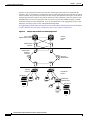
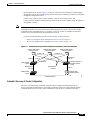
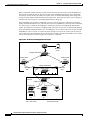
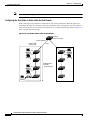
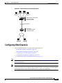
Advantages of Using CMS and Clustering Switches
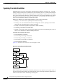
Using CMS and switch clusters can simplify and minimize your configuration and monitoring tasks. You
can use Cisco switch clustering technology to manage up to 16 interconnected and supported Catalyst
switches through one IP address as if they were a single entity. This can conserve IP addresses if you
have a limited number of them. CMS is the easiest interface to use and makes switch and switch cluster
management accessible to authorized users from any PC on your network.
By using switch clusters and CMS, you can:
•
Manage and monitor interconnected Catalyst switches (refer to the release notes for a list of
supported switches), regardless of their geographic proximity and interconnection media, including
Ethernet, Fast Ethernet, Fast EtherChannel, Cisco GigaStack Gigabit Interface Converter (GBIC),
Gigabit Ethernet, and Gigabit EtherChannel connections.
•
Accomplish multiple configuration tasks from a single CMS window without needing to remember
CLI commands to accomplish specific tasks.
•
Apply actions from CMS to multiple ports and multiple switches at the same time to avoid
re-entering the same commands for each individual port or switch. Here are some examples of
globally setting and managing multiple ports and switches:
– Port configuration such as speed and duplex settings
– Port and console port security settings
– NTP, STP, VLAN, and quality of service (QoS) configurations
– Inventory and statistic reporting and link and switch-level monitoring and troubleshooting
– Group software upgrades
•
View a topology of interconnected devices to identify existing switch clusters and eligible switches
that can join a cluster. You can also use the topology to quickly identify link information between
switches.
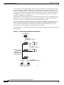
•
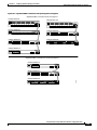
Monitor real-time status of a switch or multiple switches from the LEDs on the front-panel images.
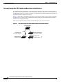
The system, redundant power system (RPS), and port LED colors on the images are similar to those
on the physical LEDs.
•
Use an interactive mode that takes you step-by-step through configuring complex features such as
VLANs, ACLs, and QoS.
•
Use a wizard that prompts you to provide the minimum required information to configure complex
features such as QoS priorities for video traffic, priority levels for data applications, and security.
For more information about CMS, see Chapter 4, “Getting Started with CMS.” For more information
about switch clusters, see Chapter 7, “Clustering Switches.”
Network Configuration Examples
This section provides network configuration concepts and includes examples of using the switch to
create dedicated network segments and interconnecting the segments through Fast Ethernet and Gigabit
Ethernet connections.
Note
The examples in this section show the Catalyst 2950 switch but also apply to the Catalyst 2955 switch.
Catalyst 2950 and Catalyst 2955 Switch Software Configuration Guide
1-8
78-11380-07
Chapter 1
Overview
Network Configuration Examples
Design Concepts for Using the Switch
As your network users compete for network bandwidth, it takes longer to send and receive data. When
you configure your network, consider the bandwidth required by your network users and the relative
priority of the network applications they use.
Table 1-2 describes what can cause network performance to degrade and how you can configure your
network to increase the bandwidth available to your network users.
Table 1-2
Increasing Network Performance
Network Demands
Suggested Design Methods
Too many users on a single network segment
and a growing number of users accessing the
Internet
•
Increased power of new PCs,
workstations, and servers
•
High demand from networked
applications (such as e-mail with large
attached files) and from
bandwidth-intensive applications (such
as multimedia)
•
Create smaller network segments so that fewer users share the
bandwidth, and use VLANs and IP subnets to place the network
resources in the same logical network as the users who access those
resources most.
•
Use full-duplex operation between the switch and its connected
workstations.
•
Connect global resources—such as servers and routers to which network
users require equal access—directly to the Fast Ethernet or Gigabit
Ethernet switch ports so that they have their own Fast Ethernet or Gigabit
Ethernet segment.
•
Use the Fast EtherChannel or Gigabit EtherChannel feature between the
switch and its connected servers and routers.
Bandwidth alone is not the only consideration when designing your network. As your network traffic
profiles evolve, consider providing network services that can support applications such as voice and data
integration and security.
Table 1-3 describes some network demands and how you can meet those demands.
Table 1-3
Providing Network Services
Network Demands
Suggested Design Methods
High demand for multimedia support
•
Use IGMP and MVR to efficiently forward multicast traffic.
High demand for protecting mission-critical
applications
•
Use VLANs and protected ports to provide security and port isolation.
•
Use VLAN trunks, cross-stack UplinkFast, and BackboneFast for
traffic-load balancing on the uplink ports so that the uplink port with a
lower relative port cost is selected to carry the VLAN traffic.
An evolving demand for IP telephony
•
Use QoS to prioritize applications such as IP telephony during
congestion and to help control both delay and jitter within the network.
•
Use switches that support at least two queues per port to prioritize voice
and data traffic as either high- or low-priority, based on 802.1P/Q.
•
Use the Catalyst 2900 LRE XL switches to provide up to 15 Mb of IP
connectivity over existing infrastructure (existing telephone lines).
A growing demand for using existing
infrastructure to transport data and voice from
a home or office to the Internet or an intranet at
higher speeds
Catalyst 2950 and Catalyst 2955 Switch Software Configuration Guide
78-11380-07
1-9
Chapter 1
Overview
Network Configuration Examples
Figure 1-1 shows configuration examples of using the Catalyst switches to create these networks:
•
Cost-effective wiring closet—A cost-effective way to connect many users to the wiring closet is to
connect up to nine Catalyst 2900 XL, Catalyst 2950, Catalyst 3500 XL, and Catalyst 3550 switches
through GigaStack GBIC connections. When you use a stack of Catalyst 2950G-48 switches, you
can connect up to 432 users. To preserve switch connectivity if one switch in the stack fails, connect
the bottom switch to the top switch to create a GigaStack loopback, and enable cross-stack
UplinkFast on the cross-stack Gigabit uplinks.
You can create backup paths by using Fast Ethernet, Gigabit, Fast EtherChannel, or Gigabit
EtherChannel links. Using Gigabit modules on two of the switches, you can have redundant uplink
connections to a Gigabit backbone switch such as the Catalyst 3550-12G switch. If one of the
redundant connections fails, the other can serve as a backup path. You can configure the stack
members and the Catalyst 3550-12G switch as a switch cluster to manage them through a single IP
address.
•
High-performance workgroup—For users who require high-speed access to network resources, use
Gigabit modules to connect the switches directly to a backbone switch in a star configuration. Each
switch in this configuration provides users with a dedicated 1-Gbps connection to network resources
in the backbone. Compare this with the switches in a GigaStack configuration, where the 1-Gbps
connection is shared among the switches. With the high speed uplink to the distribution server, the
user can efficiently obtain and store data from servers. Using these Gigabit modules also provides
flexibility in media and distance options:
– 1000BASE-T GBIC: copper connections of up to 328 feet (100 meters)
– 1000BASE-SX GBIC: fiber connections of up to 1804 feet (550 meters)
– 1000BASE-LX/LH GBIC: fiber connections of up to 32,808 feet (10 kilometers)
– 1000BASE-ZX GBIC: fiber connections of up to 328,084 feet (100 kilometers)
– GigaStack GBIC module for creating a 1-Gbps stack configuration of up to nine supported
switches. The GigaStack GBIC supports one full-duplex link (in a point-to-point configuration)
or up to nine half-duplex links (in a stack configuration) to other Gigabit Ethernet devices.
Using the required Cisco proprietary signaling and cabling, the GigaStack GBIC-to-GigaStack
GBIC connection cannot exceed 3 feet (1 meter).
•
Redundant Gigabit backbone—Using HSRP, you can create backup paths between
Catalyst 3550-12T-L3 switches. To enhance network reliability and load balancing for different
VLANs and subnets, you can connect the Catalyst 2950 switches, again in a star configuration, to
two backbone switches. If one of the backbone switches fails, the second backbone switch preserves
connectivity between the switches and network resources.
Catalyst 2950 and Catalyst 2955 Switch Software Configuration Guide
1-10
78-11380-07
Chapter 1
Overview
Network Configuration Examples
Figure 1-1
Example Configurations
Catalyst 2950 switch
Cost-Effective
Wiring Closet
Catalyst 2900 XL,
Catalyst 2950,
Catalyst 3500 XL,
and Catalyst 3550
GigaStack cluster
Catalyst 3550-12T or
Catalyst 3550-12G switch
Si
Gigabit
server
High-Performance
Workgroup
Catalyst 2900 XL, Catalyst 2950,
Catalyst 3500 XL, and Catalyst 3550 cluster
Catalyst 3550-12T or
Catalyst 3550-12T or
Catalyst 3550-12G switch
Catalyst 3550-12G switch
1-Gbps HSRP
Si
Si
Catalyst 2900 XL, Catalyst 2950,
Catalyst 3500 XL, and Catalyst 3550 cluster
60992
Redundant Gigabit
Backbone
Small to Medium-Sized Network Configuration
Figure 1-2 shows a configuration for a network that has up to 250 users. Users in this network require
e-mail, file-sharing, database, and Internet access.
You optimize network performance by placing workstations on the same logical segment as the servers
they access most often. This divides the network into smaller segments (or workgroups) and reduces the
amount of traffic that travels over a network backbone, thereby increasing the bandwidth available to
each user and improving server response time.
Catalyst 2950 and Catalyst 2955 Switch Software Configuration Guide
78-11380-07
1-11
Chapter 1
Overview
Network Configuration Examples
A network backbone is a high-bandwidth connection (such as Fast Ethernet or Gigabit Ethernet) that
interconnects segments and network resources. It is required if numerous segments require access to the
servers. The Catalyst 2900 XL, Catalyst 2950, Catalyst 3500 XL, and Catalyst 3550 switches in this
network are connected through a GigaStack GBIC on each switch to form a 1-Gbps network backbone.
This GigaStack can also be configured as a switch cluster, with primary and secondary command
switches for redundant cluster management.
Workstations are connected directly to the 10/100 switch ports for their own 10- or 100-Mbps access to
network resources (such as web and mail servers). When a workstation is configured for full-duplex
operation, it receives up to 200 Mbps of dedicated bandwidth from the switch.
Servers are connected to the GBIC module ports on the switches, allowing 1-Gbps throughput to users
when needed. When the switch and server ports are configured for full-duplex operation, the links
provide 2 Gbps of bandwidth. For networks that do not require Gigabit performance from a server,
connect the server to a Fast Ethernet or Fast EtherChannel switch port.
Connecting a router to a Fast Ethernet switch port provides multiple, simultaneous access to the Internet
through one line.
Figure 1-2
Small to Medium-Sized Network Configuration
Cisco 2600 router
100 Mbps
(200 Mbps full duplex)
Gigabit
server
1 Gbps
(2 Gbps full duplex)
Catalyst 2900 XL,
Catalyst 2950,
Catalyst 3550, and
Catalyst 3500 XL
GigaStack cluster
Gigabit
server
Single workstations
60993
10/100 Mbps
(20/200 Mbps full duplex)
Catalyst 2950 and Catalyst 2955 Switch Software Configuration Guide
1-12
78-11380-07
Chapter 1
Overview
Network Configuration Examples
Collapsed Backbone and Switch Cluster Configuration
Figure 1-3 shows a configuration for a network of approximately 500 employees. This network uses a
collapsed backbone and switch clusters. A collapsed backbone has high-bandwidth uplinks from all
segments and subnetworks to a single device, such as a Gigabit switch, that serves as a single point for
monitoring and controlling the network. You can use a Catalyst 3550-12T-L3 switch, as shown, or a
Catalyst 3508G XL switch to create a Gigabit backbone. A Catalyst 3550-12T-L3 backbone switch
provides the benefits of inter-VLAN routing and allows the router to focus on WAN access.
The workgroups are created by clustering all the Catalyst switches except the Catalyst 4908G-L3 switch.
Using CMS and Cisco switch clustering technology, you can group the switches into multiple clusters,
as shown, or into a single cluster. You can manage a cluster through the IP address of its active and
standby command switches, regardless of the geographic location of the cluster members.
This network uses VLANs to segment the network logically into well-defined broadcast groups and for
security management. Data and multimedia traffic are configured on the same VLAN. Voice traffic from
the Cisco IP Phones are configured on separate voice VLAN IDs (VVIDs). You can have up to
four VVIDs per wiring closet. If data, multimedia, and voice traffic are assigned to the same VLAN, only
one VLAN can be configured per wiring closet. For any switch port connected to Cisco IP Phones,
802.1P/Q QoS gives forwarding priority to voice traffic over data traffic.
Grouping servers in a centralized location provides benefits such as security and easier maintenance. The
Gigabit connections to a server farm provide the workgroups full access to the network resources (such
as a call-processing server running Cisco CallManager software, a DHCP server, or an IP/TV multicast
server).
Cisco IP Phones are connected—using standard straight-through, twisted-pair cable with RJ-45
connectors—to the 10/100 inline-power ports on the Catalyst 3524-PWR XL switches and to the
10/100 ports on the Catalyst 2950 switches. These multiservice switch ports automatically detect any IP
phones that are connected. Cisco CallManager controls call processing, routing, and IP phone features
and configuration. Users with workstations running Cisco SoftPhone software can place, receive, and
control calls from their PCs. Using Cisco IP Phones, Cisco CallManager software, and Cisco SoftPhone
software integrates telephony and IP networks, and the IP network supports both voice and data.
Each 10/100 inline-power port on the Catalyst 3524-PWR XL switches provides –48 VDC power to the
Cisco IP Phone. The IP phone can receive redundant power when it is also connected to an AC power
source. IP phones not connected to the Catalyst 3524-PWR XL switches receive power from an AC
power source.
Catalyst 2950 and Catalyst 2955 Switch Software Configuration Guide
78-11380-07
1-13
Chapter 1
Overview
Network Configuration Examples
Figure 1-3
Collapsed Backbone and Switch Cluster Configuration
Gigabit
servers
Cisco
CallManager
Catalyst 3550-12T or
Catalyst 3550-12G switch
Cisco 2600 router
Si
200 Mbps
Fast EtherChannel
(400-Mbps full-duplex
Fast EtherChannel)
1 Gbps
(2 Gbps full duplex)
Catalyst
2950,
2900 XL,
3550, and
3500 XL
GigaStack cluster
Catalyst 2950, 2900 XL,
3550, and 3500 XL
GigaStack cluster
Catalyst
3524-PWR XL
GigaStack cluster
IP
IP
IP
Workstations running
Cisco SoftPhone software
IP
IP
Cisco IP Phones
60994
Cisco
IP Phones
Large Campus Configuration
Figure 1-4 shows a configuration for a network of more than 1000 users. Because it can aggregate up to
130 Gigabit connections, a Catalyst 6500 multilayer switch is used as the backbone switch.
You can use the workgroup configurations shown in previous examples to create workgroups with
Gigabit uplinks to the Catalyst 6500 switch. For example, you can use switch clusters that have a mix of
Catalyst 2950 switches.
The Catalyst 6500 switch provides the workgroups with Gigabit access to core resources:
•
Cisco 7000 series router for access to the WAN and the Internet.
•
Server farm that includes a call-processing server running Cisco CallManager software. Cisco
CallManager controls call processing, routing, and IP phone features and configuration.
•
Cisco Access gateway (such as Cisco Access Digital Trunk Gateway or Cisco Access Analog Trunk
Gateway) that connects the IP network to the Public Switched Telephone Network (PSTN) or to
users in an IP telephony network.
Catalyst 2950 and Catalyst 2955 Switch Software Configuration Guide
1-14
78-11380-07
Chapter 1
Overview
Network Configuration Examples
Figure 1-4
Large Campus Configuration
IP telephony
network or
PSTN
WAN
Cisco
CallManager
Cisco 7200 Cisco access
or 7500 router gateway
Servers
Catalyst
6500 switch
Catalyst 2950, 2900 XL,
3500 XL, and 3550
GigaStack cluster
1 Gbps
(2 Gbps
full duplex)
Catalyst
3524-PWR XL
GigaStack cluster
IP
IP
Cisco IP Phones
IP
IP
Cisco IP Phones
60995
Workstations running
Cisco SoftPhone software
IP
Multidwelling Network Using Catalyst 2950 Switches
A growing segment of residential and commercial customers are requiring high-speed access to Ethernet
metropolitan-area networks (MANs). Figure 1-5 shows a configuration for a Gigabit Ethernet MAN ring
using Catalyst 3550 multilayer switches as aggregation switches in the mini-point-of-presence (POP)
location. These switches are connected through 1000BASE-X GBIC ports.
The resident switches can be Catalyst 2950 switches, providing customers with high-speed connections
to the MAN. Catalyst 2912-LRE or 2924-LRE XL Layer 2-only switches also can be used as residential
switches for customers requiring connectivity through existing telephone lines. The Catalyst 2912-LRE
or 2924-LRE XL switches can then connect to another residential switch or to an aggregation switch.
For more information about the LRE switches, refer to the Catalyst 2900 Series XL Hardware
Installation Guide.
Catalyst 2950 and Catalyst 2955 Switch Software Configuration Guide
78-11380-07
1-15
Chapter 1
Overview
Network Configuration Examples
All ports on the residential Catalyst 2950 switches (and Catalyst 2912-LRE XL or 2924-LRE XL
switches if they are included) are configured as 802.1Q trunks with protected port and STP root guard
features enabled. The protected port feature provides security and isolation between ports on the switch,
ensuring that subscribers cannot view packets destined for other subscribers. STP root guard prevents
unauthorized devices from becoming the STP root switch. All ports have IGMP snooping or CGMP
enabled for multicast traffic management. ACLs on the uplink ports to the aggregating Catalyst 3550
multilayer switches provide security and bandwidth management.
The aggregating switches and routers provide services such as those described in the previous examples,
“Small to Medium-Sized Network Configuration” and “Large Campus Configuration.”
Figure 1-5
Catalyst 2950 Switches in a MAN Configuration
Cisco 12000
Gigabit switch routers
Catalyst 6500
switches
Catalyst 3550
multilayer
switches
Service
Provider
POP
Si
Si
Si
Si
Si
Si
Si
Mini-POP
Gigabit MAN
Si
Catalyst
switches
Residential
location
Set-top box
Residential
gateway (hub)
Set-top box
50833
TV
PC
TV
Catalyst 2950 and Catalyst 2955 Switch Software Configuration Guide
1-16
78-11380-07
Chapter 1
Overview
Network Configuration Examples
Long-Distance, High-Bandwidth Transport Configuration
Note
To use the feature described in this section, you must have the EI installed on your switch.
Figure 1-6 shows a configuration for transporting Gigabits of data from one location to an off-site
backup facility over a single fiber-optic cable. The Catalyst switches have Coarse Wave Division
Multiplexer (CWDM) fiber-optic GBIC modules installed. The CWDM GBIC modules can connect to
distances of up to 393,701 feet (74.5 miles or 120 kilometers). Depending on the CWDM GBIC module,
data is sent at wavelengths from 1470 to 1610 nanometers (nm). The higher the wavelength, the farther
the transmission can travel. A common wavelength for long-distance transmissions is 1550 nm.
Up to eight CWDM GBIC modules, with any combination of wavelengths, can connect to a Cisco
CWDM Passive Optical System. It combines (or multiplexes) the different CWDM wavelengths,
allowing them to travel simultaneously on the same fiber-optic cable. The Cisco CWDM Passive Optical
System on the receiving end separates (or demultiplexes) the different wavelengths.
Using CWDM technology with the switches translates to farther data transmission and an increased
bandwidth capacity (up to 8 Gbps) on a single fiber-optic cable.
For more information about the CWDM GBIC modules and CWDM Passive Optical System, refer to the
CWDM Passive Optical System Installation Note.
Figure 1-6
Long-Distance, High-Bandwidth Transport Configuration
CWDM
OADM
modules
Eight
1-Gbps
connections
CWDM
OADM
modules
Catalyst 4000
multilayer
switches
Aggregation layer
74089
8 Gbps
Catalyst 2900 XL,
Catalyst 2950,
Catalyst 3500 XL, and
Catalyst 3550 switches
Access layer
Catalyst 2950 and Catalyst 2955 Switch Software Configuration Guide
78-11380-07
1-17
Chapter 1
Overview
Where to Go Next
Where to Go Next
Before configuring the switch, review these sections for start up information:
•
Chapter 2, “Using the Command-Line Interface”
•
Chapter 4, “Getting Started with CMS”
•
Chapter 5, “Assigning the Switch IP Address and Default Gateway”
•
Chapter 6, “Configuring IE2100 CNS Agents”
Catalyst 2950 and Catalyst 2955 Switch Software Configuration Guide
1-18
78-11380-07
C H A P T E R
2
Using the Command-Line Interface
This chapter describes the IOS command-line interface (CLI) that you can use to configure your
Catalyst 2950 and Catalyst 2955 switches. It contains these sections:
•
IOS Command Modes, page 2-1
•
Getting Help, page 2-3
•
Abbreviating Commands, page 2-4
•
Using no and default Forms of Commands, page 2-4
•
Understanding CLI Messages, page 2-5
•
Using Command History, page 2-5
•
Using Editing Features, page 2-6
•
Searching and Filtering Output of show and more Commands, page 2-9
•
Accessing the CLI, page 2-9
IOS Command Modes
The Cisco IOS user interface is divided into many different modes. The commands available to you
depend on which mode you are currently in. Enter a question mark (?) at the system prompt to obtain a
list of commands available for each command mode.
When you start a session on the switch, you begin in user mode, often called user EXEC mode. Only a
limited subset of the commands are available in user EXEC mode. For example, most of the user EXEC
commands are one-time commands, such as show commands, which show the current configuration
status, and clear commands, which clear counters or interfaces. The user EXEC commands are not saved
when the switch reboots.
To have access to all commands, you must enter privileged EXEC mode. Normally, you must enter a
password to enter privileged EXEC mode. From this mode, you can enter any privileged EXEC
command or enter global configuration mode.
Using the configuration modes (global, interface, and line), you can make changes to the running
configuration. If you save the configuration, these commands are stored and used when the switch
reboots. To access the various configuration modes, you must start at global configuration mode. From
global configuration mode, you can enter interface configuration mode and line configuration mode.
Catalyst 2950 and Catalyst 2955 Switch Software Configuration Guide
78-11380-07
2-1
Chapter 2
Using the Command-Line Interface
IOS Command Modes
Table 2-1 describes the main command modes, how to access each one, the prompt you see in that mode, and
how to exit the mode. The examples in the table use the host name Switch.
Table 2-1
Command Mode Summary
Mode
Access Method
Prompt
Exit Method
About This Mode
User EXEC
Begin a session with
your switch.
Switch>
Enter logout or quit.
Use this mode to
•
Change terminal
settings.
•
Perform basic tests.
•
Display system
information.
Privileged EXEC
While in user EXEC
mode, enter the
enable command.
Switch#
Enter disable to exit.
Use this mode to verify
commands that you have
entered. Use a password to
protect access to this mode.
Global configuration
While in privileged
EXEC mode, enter
the configure
command.
Switch(config)#
To exit to privileged
EXEC mode, enter
exit or end, or press
Ctrl-Z.
Use this mode to configure
parameters that apply to the
entire switch.
Config-vlan
While in global
configuration mode,
enter the
vlan vlan-id
command.
Switch(config-vlan)#
To exit to global
configuration mode,
enter the exit
command.
VLAN configuration
While in privileged
EXEC mode, enter
the vlan database
command.
Switch(vlan)#
To exit to privileged
EXEC mode, enter
exit.
Use this mode to configure
VLAN parameters. When
VTP mode is transparent,
you can create
extended-range VLANs
To return to
(VLAN IDs greater than
privileged EXEC
1005) and save
mode, press Ctrl-Z or
configurations in the switch
enter end.
startup configuration file.
Use this mode to configure
VLAN parameters for
VLANs 1 to 1005 in the
VLAN database.
Catalyst 2950 and Catalyst 2955 Switch Software Configuration Guide
2-2
78-11380-07
Chapter 2
Using the Command-Line Interface
Getting Help
Table 2-1
Command Mode Summary (continued)
Mode
Access Method
Prompt
Exit Method
About This Mode
Interface
configuration
While in global
configuration mode,
enter the interface
command (with a
specific interface).
Switch(config-if)#
To exit to global
configuration mode,
enter exit.
Use this mode to configure
parameters for the Ethernet
interfaces.
To return to
privileged EXEC
mode, press Ctrl-Z or
enter end.
To configure multiple
interfaces with the same
parameters, see the
“Configuring a Range of
Interfaces” section on
page 11-6.
While in global
configuration mode,
specify a line with
the line vty or line
console command.
Switch(config-line)#
To exit to global
configuration mode,
enter exit.
Use this mode to configure
parameters for the terminal
line.
Line configuration
To return to
privileged EXEC
mode, press Ctrl-Z or
enter end.
Getting Help
You can enter a question mark (?) at the system prompt to display a list of commands available for each
command mode. You can also obtain a list of associated keywords and arguments for any command, as
shown in Table 2-2.
Table 2-2
Help Summary
Command
Purpose
help
Obtain a brief description of the help system in any command mode.
abbreviated-command-entry?
Obtain a list of commands that begin with a particular character string.
For example:
Switch# di?
dir disable
abbreviated-command-entry<Tab>
disconnect
Complete a partial command name.
For example:
Switch# sh conf<tab>
Switch# show configuration
?
List all commands available for a particular command mode.
For example:
Switch> ?
Catalyst 2950 and Catalyst 2955 Switch Software Configuration Guide
78-11380-07
2-3
Chapter 2
Using the Command-Line Interface
Abbreviating Commands
Table 2-2
Help Summary (continued)
Command
Purpose
command ?
List the associated keywords for a command.
For example:
Switch> show ?
command keyword ?
List the associated arguments for a keyword.
For example:
Switch(config)# cdp holdtime ?
<10-255> Length of time (in sec) that receiver must keep this packet
Abbreviating Commands
You have to enter only enough characters for the switch to recognize the command as unique. This
example shows how to enter the show configuration privileged EXEC command:
Switch# show conf
Using no and default Forms of Commands
Almost every configuration command also has a no form. In general, use the no form to disable a feature
or function or reverse the action of a command. For example, the no shutdown interface configuration
command reverses the shutdown of an interface. Use the command without the keyword no to re-enable
a disabled feature or to enable a feature that is disabled by default.
Configuration commands can also have a default form. The default form of a command returns the
command setting to its default. Most commands are disabled by default, so the default form is the same
as the no form. However, some commands are enabled by default and have variables set to certain default
values. In these cases, the default command enables the command and sets variables to their default
values.
Catalyst 2950 and Catalyst 2955 Switch Software Configuration Guide
2-4
78-11380-07
Chapter 2
Using the Command-Line Interface
Understanding CLI Messages
Understanding CLI Messages
Table 2-3 lists some error messages that you might encounter while using the CLI to configure your
switch.
Table 2-3
Common CLI Error Messages
Error Message
Meaning
How to Get Help
% Ambiguous command:
"show con"
You did not enter enough characters
for your switch to recognize the
command.
Re-enter the command followed by a question mark (?)
with a space between the command and the question
mark.
The possible keywords that you can enter with the
command are displayed.
You did not enter all the keywords or Re-enter the command followed by a question mark (?)
values required by this command.
with a space between the command and the question
mark.
% Incomplete command.
The possible keywords that you can enter with the
command are displayed.
% Invalid input detected
at ‘^’ marker.
You entered the command
incorrectly. The caret (^) marks the
point of the error.
Enter a question mark (?) to display all the commands
that are available in this command mode.
The possible keywords that you can enter with the
command are displayed.
Using Command History
The IOS provides a history or record of commands that you have entered. This feature is particularly
useful for recalling long or complex commands or entries, including access lists. You can customize the
command history feature to suit your needs as described in these sections:
•
Changing the Command History Buffer Size, page 2-5
•
Recalling Commands, page 2-6
•
Disabling the Command History Feature, page 2-6
Changing the Command History Buffer Size
By default, the switch records ten command lines in its history buffer. Beginning in privileged EXEC
mode, enter this command to change the number of command lines that the switch records during the
current terminal session:
Switch# terminal history [size number-of-lines]
The range is from 0 to 256.
Beginning in line configuration mode, enter this command to configure the number of command lines
the switch records for all sessions on a particular line:
Switch(config-line)# history
[size
number-of-lines]
The range is from 0 to 256.
Catalyst 2950 and Catalyst 2955 Switch Software Configuration Guide
78-11380-07
2-5
Chapter 2
Using the Command-Line Interface
Using Editing Features
Recalling Commands
To recall commands from the history buffer, perform one of the actions listed in Table 2-4:
Table 2-4
Recalling Commands
Action1
Result
Press Ctrl-P or the up arrow key.
Recall commands in the history buffer, beginning with the most recent command.
Repeat the key sequence to recall successively older commands.
Press Ctrl-N or the down arrow key.
Return to more recent commands in the history buffer after recalling commands
with Ctrl-P or the up arrow key. Repeat the key sequence to recall successively
more recent commands.
show history
While in privileged EXEC mode, list the last several commands that you just
entered. The number of commands that are displayed is determined by the setting
of the terminal history global configuration command and history line
configuration command.
1. The arrow keys function only on ANSI-compatible terminals such as VT100s.
Disabling the Command History Feature
The command history feature is automatically enabled.
To disable the feature during the current terminal session, enter the terminal no history privileged
EXEC command.
To disable command history for the line, enter the no history line configuration command.
Using Editing Features
This section describes the editing features that can help you manipulate the command line. It contains
these sections:
•
Enabling and Disabling Editing Features, page 2-7
•
Editing Commands through Keystrokes, page 2-7
•
Editing Command Lines that Wrap, page 2-8
Catalyst 2950 and Catalyst 2955 Switch Software Configuration Guide
2-6
78-11380-07
Chapter 2
Using the Command-Line Interface
Using Editing Features
Enabling and Disabling Editing Features
Although enhanced editing mode is automatically enabled, you can disable it.
To re-enable the enhanced editing mode for the current terminal session, enter this command in
privileged EXEC mode:
Switch# terminal editing
To reconfigure a specific line to have enhanced editing mode, enter this command in line configuration
mode:
Switch(config-line)# editing
To globally disable enhanced editing mode, enter this command in line configuration mode:
Switch(config-line)# no editing
Editing Commands through Keystrokes
Table 2-5 shows the keystrokes that you need to edit command lines.
Table 2-5
Editing Commands through Keystrokes
Capability
Keystroke1
Move around the command line to
make changes or corrections.
Press Ctrl-B, or press the Move the cursor back one character.
left arrow key.
Purpose
Press Ctrl-F, or press the
right arrow key.
Move the cursor forward one character.
Press Ctrl-A.
Move the cursor to the beginning of the command line.
Press Ctrl-E.
Move the cursor to the end of the command line.
Press Esc B.
Move the cursor back one word.
Press Esc F.
Move the cursor forward one word.
Press Ctrl-T.
Transpose the character to the left of the cursor with the
character located at the cursor.
Recall commands from the buffer and Press Ctrl-Y.
paste them in the command line. The
switch provides a buffer with the last
ten items that you deleted.
Press Esc Y.
Recall the most recent entry in the buffer.
Recall the next buffer entry.
The buffer contains only the last 10 items that you have
deleted or cut. If you press Esc Y more than ten times, you
cycle to the first buffer entry.
Delete entries if you make a mistake Press the Delete or
or change your mind.
Backspace key.
Erase the character to the left of the cursor.
Catalyst 2950 and Catalyst 2955 Switch Software Configuration Guide
78-11380-07
2-7
Chapter 2
Using the Command-Line Interface
Using Editing Features
Table 2-5
Editing Commands through Keystrokes (continued)
Capability
Capitalize or lowercase words or
capitalize a set of letters.
Keystroke1
Purpose
Press Ctrl-D.
Delete the character at the cursor.
Press Ctrl-K.
Delete all characters from the cursor to the end of the
command line.
Press Ctrl-U or Ctrl-X.
Delete all characters from the cursor to the beginning of
the command line.
Press Ctrl-W.
Delete the word to the left of the cursor.
Press Esc D.
Delete from the cursor to the end of the word.
Press Esc C.
Capitalize at the cursor.
Press Esc L.
Change the word at the cursor to lowercase.
Press Esc U.
Capitalize letters from the cursor to the end of the word.
Designate a particular keystroke as
Press Ctrl-V or Esc Q.
an executable command, perhaps as a
shortcut.
Scroll down a line or screen on
displays that are longer than the
terminal screen can display.
Note
Press the Return key.
Scroll down one line.
Press the Space bar.
Scroll down one screen.
Press Ctrl-L or Ctrl-R.
Redisplay the current command line.
The More prompt is used for
any output that has more
lines than can be displayed
on the terminal screen,
including show command
output. You can use the
Return and Space bar
keystrokes whenever you see
the More prompt.
Redisplay the current command line
if the switch suddenly sends a
message to your screen.
1. The arrow keys function only on ANSI-compatible terminals such as VT100s.
Editing Command Lines that Wrap
You can use a wraparound feature for commands that extend beyond a single line on the screen. When
the cursor reaches the right margin, the command line shifts ten spaces to the left. You cannot see the
first ten characters of the line, but you can scroll back and check the syntax at the beginning of the
command.
To scroll back to the beginning of the command entry, press Ctrl-B or the left arrow key repeatedly. You
can also press Ctrl-A to immediately move to the beginning of the line.
Note
The arrow keys function only on ANSI-compatible terminals such as VT100s.
Catalyst 2950 and Catalyst 2955 Switch Software Configuration Guide
2-8
78-11380-07
Chapter 2
Using the Command-Line Interface
Searching and Filtering Output of show and more Commands
In this example, the access-list global configuration command entry extends beyond one line. When the
cursor first reaches the end of the line, the line is shifted ten spaces to the left and redisplayed. The dollar
sign ($) shows that the line has been scrolled to the left. Each time the cursor reaches the end of the line,
the line is again shifted ten spaces to the left.
Switch(config)#
Switch(config)#
Switch(config)#
Switch(config)#
access-list 101 permit tcp 131.108.2.5 255.255.255.0 131.108.1
$ 101 permit tcp 131.108.2.5 255.255.255.0 131.108.1.20 255.25
$t tcp 131.108.2.5 255.255.255.0 131.108.1.20 255.255.255.0 eq
$108.2.5 255.255.255.0 131.108.1.20 255.255.255.0 eq 45
After you complete the entry, press Ctrl-A to check the complete syntax before pressing the Return key
to execute the command. The dollar sign ($) appears at the end of the line to show that the line has been
scrolled to the right:
Switch(config)# access-list 101 permit tcp 131.108.2.5 255.255.255.0 131.108.1$
The software assumes you have a terminal screen that is 80 columns wide. If you have a width other than
that, use the terminal width privileged EXEC command to set the width of your terminal.
Use line wrapping with the command history feature to recall and modify previous complex command
entries. For information about recalling previous command entries, see the “Editing Commands through
Keystrokes” section on page 2-7.
Searching and Filtering Output of show and more Commands
You can search and filter the output for show and more commands. This is useful when you need to sort
through large amounts of output or if you want to exclude output that you do not need to see.
To use this functionality, enter a show or more command followed by the pipe character (|), one of the
keywords begin, include, or exclude, and an expression that you want to search for or filter out:
command | {begin | include | exclude} regular-expression
Expressions are case sensitive. For example, if you enter | exclude output, the lines that contain output
are not displayed, but the lines that contain Output are displayed.
This example shows how to include in the output display only lines where the expression protocol
appears:
Switch# show interfaces | include protocol
Vlan1 is up, line protocol is up
Vlan10 is up, line protocol is down
GigabitEthernet0/1 is up, line protocol is down
GigabitEthernet0/2 is up, line protocol is up
Accessing the CLI
Before you can access the CLI, you need to connect a terminal or PC to the switch console port and
power on the switch as described in the hardware installation guide that shipped with your switch. Then,
to understand the boot process and the options available for assigning IP information, see Chapter 5,
“Assigning the Switch IP Address and Default Gateway.”
If your switch is already configured, you can access the CLI through a local console connection or
through a remote Telnet session, but your switch must first be configured for this type of access. For
more information, see the “Setting a Telnet Password for a Terminal Line” section on page 9-5.
Catalyst 2950 and Catalyst 2955 Switch Software Configuration Guide
78-11380-07
2-9
Chapter 2
Using the Command-Line Interface
Accessing the CLI from a Browser
You can establish a connection with the switch by either
•
Connecting the switch console port to a management station or dial-up modem. For information
about connecting to the console port, refer to the switch hardware installation guide.
•
Using any Telnet TCP/IPor encrypted Secure Shell (SSH) package from a remote management
station. The switch must have network connectivity with the Telnet or SSH client, and the switch
must have an enable secret password configured.
For information about configuring the switch for Telnet access, see the “Setting a Telnet Password
for a Terminal Line” section on page 9-5. The switch supports up to 16 simultaneous Telnet sessions.
Changes made by one Telnet user are reflected in all other Telnet sessions.
For information about configuring the switch for SSH, see the “Configuring the Switch for Secure
Shell” section on page 9-31. The switch supports up to five simultaneous secure SSH sessions.
After you connect through the console port, through a Telnet session, or through an SSH session, the
user EXEC prompt appears on the management station.
Accessing the CLI from a Browser
This procedure assumes you have met the software requirements (including browser and Java plug-in
configurations) and have assigned IP information and a Telnet password to the switch or command
switch, as described in the release notes.
To access the CLI from a web browser, follow these steps:
Step 1
Start one of the supported browsers.
Step 2
In the URL field, enter the IP address of the command switch.
Step 3
When the Cisco Systems Access page appears, click Telnet to start a Telnet session.
You can also access the CLI by clicking Monitor the router- HTML access to the command line
interface from the Cisco Systems Access page. For information about the Cisco Systems Access page,
see the “Accessing CMS” section in the release notes.
Step 4
Enter the switch password.
The user EXEC prompt appears on the management station.
Note
Copies of the CMS pages that you display are saved in your browser memory cache until you exit the
browser session. A password is not required to redisplay these pages, including the Cisco Systems
Access page. You can access the CLI by clicking Web Console - HTML access to the command line
interface from a cached copy of the Cisco Systems Access page. To prevent unauthorized access to CMS
and the CLI, exit your browser to end the browser session.
Catalyst 2950 and Catalyst 2955 Switch Software Configuration Guide
2-10
78-11380-07
C H A P T E R
3
Configuring Catalyst 2955 Switch Alarms
This section describes how to configure the different alarms for the Catalyst 2955 switch.
Note
The alarms described in this chapter are not available on the Catalyst 2950 switch.
For complete syntax and usage information for the commands used in this chapter, refer to the switch
command reference for this release.
This chapter consists of these sections:
•
Understanding Catalyst 2955 Switch Alarms, page 3-1
•
Configuring Catalyst 2955 Switch Alarms, page 3-4
•
Displaying Catalyst 2955 Switch Alarms Status, page 3-12
Understanding Catalyst 2955 Switch Alarms
The Catalyst 2955 switch software monitors switch conditions on a per port or a switch basis. If the
conditions present on the switch or port do not match the parameters set by the user, the switch software
triggers an alarm or a system message. By default, the switch software sends the system messages to a
system message logging facility, or a syslog facility. You can also configure the switch to send Simple
Network Management Protocol (SNMP) traps to an SNMP server. You can configure the switch to
trigger an external alarm device by using the two independent alarm relays (major or minor). For more
information on how to configure the alarms, see the “Configuring Catalyst 2955 Switch Alarms” section
on page 3-4.
This section includes information about these topics:
•
Global Status Monitoring Alarms, page 3-2
•
FCS Error Hysteresis Threshold, page 3-2
•
Port Status Monitoring Alarms, page 3-3
•
Triggering Alarm Options, page 3-4
Catalyst 2950 and Catalyst 2955 Switch Software Configuration Guide
78-11380-07
3-1
Chapter 3
Configuring Catalyst 2955 Switch Alarms
Understanding Catalyst 2955 Switch Alarms
Global Status Monitoring Alarms
The Catalyst 2955 switch contains facilities for processing alarms related to temperature and power
supply conditions. These are referred to as global or facility alarms. Table 3-1 lists the three global
alarms and their descriptions and functions.
Table 3-1
Catalyst 2955 Global Status Monitoring Alarms
Alarm
Description
Power Supply Alarm
The Catalyst 2955 switch monitors dual DC power supply levels. If the system is
configured to operate in a dual power mode, an alarm triggers if a power supply fails or
is missing. The alarm is automatically cleared when both power supplies are present or
working. You can configure the power supply alarm to be connected to the hardware
relays. For more information, see the “Configuring the Power Supply Alarm” section on
page 3-5.
Temperature Alarms
The Catalyst 2955 switch contains a temperature sensor that monitors the environmental
conditions inside the switch. The switch contains two alarms that are associated with
temperature.
•
The primary alarm is enabled automatically to trigger both at a low temperature
(-20oC) and a high temperature (95oC) for the safe operation of the switch. It cannot
be changed or disabled. By default, the primary temperature alarm is associated with
the major relay.
•
You can use the secondary temperature alarm to trigger an alarm when the system
temperature is greater than the configured temperature threshold. The lower threshold
is configurable within the range of 40oC to the maximum threshold, 95oC. The
secondary alarm is disabled by default.
For more information, see the “Configuring the Switch Temperature Alarms” section on
page 3-6.
FCS Error Hysteresis Threshold
The Ethernet standard calls for a maximum bit error rate of 10-8. In the Catalyst 2955 switch, the bit
error rate configurable range is from 10-6 to 10 -11. The bit error rate input to the switch is a positive
exponent. If you want to configure the bit error rate of 10-9, then you enter the value 9 for the exponent.
By default, the FCS bit error rate is 10-8.
You can set the FCS error hysteresis threshold to prevent the toggle of the alarm when the actual bit error
rate fluctuates near the configured bit error rate. The hysteresis threshold is defined as the ratio between
the alarm clear threshold to the alarm set threshold, expressed as a percentage value.
Catalyst 2950 and Catalyst 2955 Switch Software Configuration Guide
3-2
78-11380-07
Chapter 3
Configuring Catalyst 2955 Switch Alarms
Understanding Catalyst 2955 Switch Alarms
For example, if the FCS bit error rate alarm value is configured to 10–8, that value is the alarm set
threshold. To set the alarm clear threshold at 5*10 -10, the hysteresis, value h, is determined as follows:
h = alarm clear threshold / alarm set threshold
h = 5*10 -10 / 10-8 = 5*10-2 = 0.05 = 5 percent
The FCS hysteresis threshold is applied to all ports on the Catalyst 2955 switch. The allowable range is
from 1 to 10 percent. The default value is 10 percent. See the “Configuring the FCS Bit Error Rate
Alarm” section on page 3-8 for more information.
Port Status Monitoring Alarms
The Catalyst 2955 switch can also monitor the status of the Ethernet ports and generate alarm messages
based on the alarms listed in Table 3-2. To save user time and effort, the switch supports changing alarm
configurations by using alarm profiles. You can create a number of profiles and assign one of these
profiles to each Ethernet port.
Alarm profiles provide a mechanism for you to enable or disable alarm conditions for a port and
associate the alarm conditions with one or both alarm relays. You can also use alarm profiles to set alarm
conditions to send alarm traps to an SNMP server and system messages to a syslog server. The alarm
profile defaultPort is applied to all interfaces in the factory configuration (by default).
Note
You can associate multiple alarms to one relay or one alarm to both relays.
Table 3-2 lists the port status monitoring alarms and their descriptions and functions. Each fault
condition is assigned a severity level based on the Cisco IOS System Error Message Severity Level.
Table 3-2
Catalyst 2955 Port Status Monitoring Alarms
Alarm
Description
Link Fault alarm
The Catalyst 2955 switch generates a link fault alarm when there are problems with a port
physical layer that cause unreliable data transmission. A typical link fault condition is loss
of signal or clock. The link fault alarm is cleared automatically when the link fault
condition is cleared. The severity for this alarm is error condition, level 3.
Port not Forwarding
alarm
The switch generates a port not forwarding alarm when a port is not forwarding packets.
This alarm is cleared automatically when the port begins to forward packets. The severity
for this alarm is warning, level 4.
Port is not Operating
alarm
The switch generates a port is not operating alarm when it finds that a port is in a failed
state during the startup self-test. When triggered, the port is not operating alarm is only
cleared when the switch is restarted and the port is found to be operational. The severity
for this alarm is error condition, level 3.
FCS Bit Error Rate alarm The switch generates an FCS Bit Error Rate alarm when the actual FCS Bit Error Rate is
close to the configured FCS Bit Error Rate. You can set the FCS bit error rate by using the
interface configuration CLI for each of the ports. See the “Configuring the FCS Bit Error
Rate Alarm” section on page 3-8 for more information. The severity for this alarm is error
condition, level 3.
Catalyst 2950 and Catalyst 2955 Switch Software Configuration Guide
78-11380-07
3-3
Chapter 3
Configuring Catalyst 2955 Switch Alarms
Configuring Catalyst 2955 Switch Alarms
Triggering Alarm Options
The Catalyst 2955 supports three methods for triggering alarms:
•
Configurable Relays
The Catalyst 2955 switch is equipped with two independent alarm relays that can be triggered by
alarms for global and port status conditions. The relays can be configured to send a fault signal to
an external alarm device, such as a bell, light, or other signaling device. You can associate any alarm
condition with either alarm relay or both relays. Each fault condition is assigned a severity level
based on the Cisco IOS System Error Message Severity Level.
See the “Configuring Catalyst 2955 Switch Alarms” section on page 3-4 for more information on
configuring the relays.
•
SNMP Traps
SNMP is an application-layer protocol that provides a message format for communication between
managers and agents. The SNMP system consists of an SNMP manager, an SNMP agent, and a
management information base (MIB).
The snmp-server enable traps command can be modified in the Catalyst 2955 switch software to
allow the user to send alarm traps to an SNMP server. You can use alarm profiles to set
environmental or port status alarm conditions to send SNMP alarm traps. See the “Enabling SNMP
Traps” section on page 3-12 for more information.
•
Syslog Messages
You can use alarm profiles to send system messages to a syslog server. See the “Configuring
Catalyst 2955 Switch Alarms” section on page 3-4 for more information.
Configuring Catalyst 2955 Switch Alarms
This section describes how to configure the Catalyst 2955 switch alarms:
•
Default Catalyst 2955 Switch Alarm Configuration, page 3-5
•
Configuring the Power Supply Alarm, page 3-5
•
Configuring the Switch Temperature Alarms, page 3-6
•
Configuring the FCS Bit Error Rate Alarm, page 3-8
•
Configuring Alarm Profiles, page 3-10
•
Enabling SNMP Traps, page 3-12
Catalyst 2950 and Catalyst 2955 Switch Software Configuration Guide
3-4
78-11380-07
Chapter 3
Configuring Catalyst 2955 Switch Alarms
Configuring Catalyst 2955 Switch Alarms
Default Catalyst 2955 Switch Alarm Configuration
Table 3-3 shows the default Catalyst 2955 switch alarms configuration.
Table 3-3
Default Catalyst 2955 Switch Alarm Configuration
Global
Alarm
Default Setting
Power Supply Alarm
Enabled in switch single power mode. No alarm.
In dual power supply mode, the default alarm notification is a
system message to the console.
Primary Temperature Alarm
Enabled for switch temperature range 950C maximum to
-20oC minimum.
The primary switch temperature alarm is associated with the
major relay.
Port
Secondary Temperature Alarm
Disabled.
Link Fault Alarm
Disabled on all interfaces.
Port not Forwarding Alarm
Disabled on all interfaces.
Port is not Operating Alarm
Enabled on all interfaces.
FCS Bit Error Rate Alarm
Disabled on all interfaces.
Configuring the Power Supply Alarm
This section describes how to configure the power supply alarm on your switch. It contains this
configuration information:
•
Setting the Power Mode, page 3-5
•
Setting the Power Supply Alarm Options, page 3-6
Setting the Power Mode
The Catalyst 2955 switch has two DC power inputs. By default, the system operates in the single power
mode. You can use the power-supply dual global configuration command to set the dual mode
operation. In dual-power mode, a second power supply gives power to the switch if the primary power
supply fails.
Beginning in privileged EXEC mode, follow these steps to set the switch to dual power mode operation:
Command
Purpose
Step 1
configure terminal
Enter global configuration mode.
Step 2
power-supply dual
Set the system to dual mode operation.
Step 3
end
Return to privileged EXEC mode.
Step 4
show alarm settings
Verify the configuration.
Step 5
copy running-config startup-config
(Optional) Save your entries in the configuration file.
Catalyst 2950 and Catalyst 2955 Switch Software Configuration Guide
78-11380-07
3-5
Chapter 3
Configuring Catalyst 2955 Switch Alarms
Configuring Catalyst 2955 Switch Alarms
Use the no power-supply dual command to disable this alarm by setting the switch back to single power
mode operation.
Setting the Power Supply Alarm Options
Use the alarm facility power-supply global configuration command to associate the power supply
alarm to a relay. You can also configure all alarms and traps associated with the power supply alarm to
be sent to syslog and the SNMP server.
Beginning in privileged EXEC mode, follow these steps to associate the power supply alarm to a relay:
Command
Purpose
Step 1
configure terminal
Enter global configuration mode.
Step 2
alarm facility power-supply relay
{major | minor}
Associate the power supply alarm to the major or minor relay.
Step 3
alarm facility power-supply notifies Configure sending power supply alarm traps to an SNMP server.
Step 4
alarm facility power-supply syslog
Configure sending power supply alarm traps to a syslog server.
Step 5
end
Return to privileged EXEC mode.
Step 6
show alarm settings
Verify the configuration.
Step 7
copy running-config startup-config
(Optional) Save your entries in the configuration file.
To disable sending the alarm to a relay, to syslog, or to an SNMP server, use the no alarm facility
power-supply relay, no alarm facility power-supply notifies, or no alarm facility power-supply
syslog global configuration commands.
Note
Before you can use the notifies command to send alarm traps to an SNMP server, you must first set up
the SNMP server by using the snmp-server enable traps alarms global configuration command. See
the “Enabling SNMP Traps” section on page 3-12.
This example sets the power-supply monitoring alarm to the minor relay.
Switch(config) # alarm facility power-supply relay minor
Configuring the Switch Temperature Alarms
The temperature thresholds for the primary temperature alarm cannot be changed, but you can change
the association of the primary temperature alarm from the major relay to the minor relay. You can also
set a lower maximum temperature threshold for the secondary temperature alarm and associate the alarm
with either the major or minor relay.
Catalyst 2950 and Catalyst 2955 Switch Software Configuration Guide
3-6
78-11380-07
Chapter 3
Configuring Catalyst 2955 Switch Alarms
Configuring Catalyst 2955 Switch Alarms
This section describes how to configure the temperature alarms on your switch. It contains this
configuration information:
•
Setting a Secondary Temperature Threshold for the Switch, page 3-7
•
Associating the Temperature Alarms to a Relay, page 3-7
Setting a Secondary Temperature Threshold for the Switch
In global configuration mode, you can use the alarm facility temperature secondary command to set
a lower temperature threshold for the secondary temperature monitoring alarm. You can also use the
alarm facility temperature secondary command to associate the secondary temperature alarm to either
the major or minor alarm relay.
Beginning in privileged EXEC mode, follow these steps to set a lower temperature threshold:
Command
Purpose
Step 1
configure terminal
Enter global configuration mode.
Step 2
alarm facility temperature
secondary threshold
Set the secondary temperature threshold value. Enter values from 40 to 95 to
set threshold from 40 oC to 95 oC.
Step 3
end
Return to privileged EXEC mode.
Step 4
show alarm settings
Verify the configuration.
Step 5
copy running-config startup-config
(Optional) Save your entries in the configuration file.
Use the no alarm facility temperature secondary threshold global configuration command to disable
the secondary temperature threshold alarm.
This example disables the secondary temperature alarm.
Switch(config) # no alarm facility temperature secondary 45
Associating the Temperature Alarms to a Relay
By default, the primary temperature alarm is associated to the major relay. You can use the alarm facility
temperature command to associate the primary temperature alarm to the minor relay, to an SNMP trap,
to a syslog message, or to associate the secondary temperature alarm to the major or minor relay, an
SNMP trap, or a syslog message.
Beginning in privileged EXEC mode, follow these steps to associate the secondary temperature alarm to
a relay:
Command
Purpose
Step 1
configure terminal
Enter global configuration mode.
Step 2
alarm facility temperature
Associate the primary or secondary temperature alarm to a relay
{primary | secondary} relay {major
| minor}
Step 3
alarm facility temperature
{primary | secondary} notifies
Configure sending primary or secondary temperature alarm traps to an
SNMP server.
Step 4
alarm facility temperature
{primary | secondary} syslog
Configure sending primary or secondary temperature alarm traps to a syslog
server.
Catalyst 2950 and Catalyst 2955 Switch Software Configuration Guide
78-11380-07
3-7
Chapter 3
Configuring Catalyst 2955 Switch Alarms
Configuring Catalyst 2955 Switch Alarms
Command
Purpose
Step 5
end
Return to privileged EXEC mode.
Step 6
show alarm settings
Verify the configuration.
Step 7
copy running-config startup-config
(Optional) Save your entries in the configuration file.
Note
Before you can use the notifies command to send alarm traps to an SNMP server, you must first set up
the SNMP server by using the snmp-server enable traps alarms global configuration command. See
the “Enabling SNMP Traps” section on page 3-12.
Use the no alarm facility temperature secondary to disable the secondary temperature alarm.
This example sets the secondary temperature alarm to the minor relay, with a lower high temperature
threshold value of 45oC. All alarm and traps associated with this alarm will be sent to a syslog server
and an SNMP server.
Switch(config)
Switch(config)
Switch(config)
Switch(config)
#
#
#
#
alarm
alarm
alarm
alarm
facility
facility
facility
facility
temperature
temperature
temperature
temperature
secondary
secondary
secondary
secondary
45
relay minor
syslog
notifies
This example sets the first (primary) temperature alarm to the major relay. All alarms and traps
associated with this alarm will be sent to a syslog server.
Switch(config) # alarm facility temperature primary syslog
Switch(config) # alarm facility temperature primary relay major
Configuring the FCS Bit Error Rate Alarm
This section describes how to configure the FCS bit error rate alarm on your switch:
•
Setting the FCS Error Threshold, page 3-8
•
Setting the FCS Error Hysteresis Threshold, page 3-9
Setting the FCS Error Threshold
The switch generates an FCS bit error rate alarm when the actual FCS bit error rate is close to the
configured FCS bit error rate. Use the fcs-threshold interface configuration command to set the FCS
error threshold.
Beginning in privileged EXEC mode, follow these steps to set the bit error rate value for a port:
Command
Purpose
Step 1
configure terminal
Enter global configuration mode.
Step 2
interface interface-id
Enter the number of the switch port to be configured, and the switch enters
interface configuration mode.
Step 3
fcs-threshold value
Set the FCS error rate.
For value, the range is 6 to 11 to set a maximum bit error rate of 10-6to 10 -11.
By default, the FCS bit error rate is 10-8.
Catalyst 2950 and Catalyst 2955 Switch Software Configuration Guide
3-8
78-11380-07
Chapter 3
Configuring Catalyst 2955 Switch Alarms
Configuring Catalyst 2955 Switch Alarms
Command
Purpose
Step 4
end
Return to privileged EXEC mode.
Step 5
show fcs-threshold
Verify the setting.
Step 6
copy running-config startup-config
(Optional) Save your entries in the configuration file.
Use the no fcs-threshold interface configuration command to go back to default FCS threshold value.
This example sets the FCS bit error rate for the Fast Ethernet port 0/1 to 10-10
Switch# configure terminal
Switch(config)# interface fastethernet0/1
Switch(config-if) # fcs-threshold 10
Setting the FCS Error Hysteresis Threshold
The hysteresis setting prevents the toggle of an alarm when the actual bit error rate fluctuates near the
configured bit error rate. Use the alarm facility fcs-hysteresis global configuration command to set the
FCS error hysteresis threshold.
Note
The FCS hysteresis threshold is applied to all ports of a Catalyst 2955 switch.
Beginning in privileged EXEC mode, follow these steps to set the FCS error hysteresis threshold for a
switch:
Command
Purpose
Step 1
configure terminal
Enter global configuration mode.
Step 2
alarm facility fcs-hysteresis
percentage
Set the hysteresis percentage for the switch.
Step 3
end
Return to privileged EXEC mode.
Step 4
show running config
Verify the configuration.
Step 5
copy running-config startup-config
(Optional) Save your entries in the configuration file.
Note
For percentage, the range is 1 to 10. The default value is 10 percent.
The show running config command displays any FCS error hysteresis that is not the default value.
This example sets FCS error hysteresis at 5 percent.
Switch(config) # alarm facility fcs-hysteresis 5
Catalyst 2950 and Catalyst 2955 Switch Software Configuration Guide
78-11380-07
3-9
Chapter 3
Configuring Catalyst 2955 Switch Alarms
Configuring Catalyst 2955 Switch Alarms
Configuring Alarm Profiles
This section describes how to configure alarm profiles on your switch. It contains this configuration
information:
•
Creating or Modifying an Alarm Profile, page 3-10
•
Attaching an Alarm Profile to a Specific Port, page 3-11
Creating or Modifying an Alarm Profile
You can use the alarm profile global configuration command to create an alarm profile or to modify an
existing profile. When you create a new alarm profile, none of the alarms are enabled.
Note
The only alarm enabled in the defaultPort profile is the Port is not Operating alarm.
Beginning in privileged EXEC mode, follow these steps to create an alarm profile:
Command
Purpose
Step 1
configure terminal
Enter global configuration mode.
Step 2
alarm profile name
Create the new profile or identify an existing profile, and then enter alarm
profile configuration mode.
Step 3
alarm alarm-id
Add or modify alarm parameters for a specific alarm (see Table 3-4). The
values are 1 to 4. You an enter more than one alarm ID separated by a space.
Step 4
notifies alarm-id
(Optional) Configure the alarm to send an SNMP trap to an SNMP server.
Step 5
relay-major alarm-id
relay-minor alarm-id
(Optional) Configure the alarm to send an alarm trap to the major relay.
Step 6
syslog alarm-id
(Optional) Configure the alarm to send an alarm trap to a syslog server.
Step 7
end
Return to privileged EXEC mode.
Step 8
show alarm profile name
Verify the configuration.
Step 9
copy running-config startup-config
(Optional) Save your entries in the configuration file.
(Optional) Configure the alarm to send an alarm trap to the minor relay.
To delete an alarm profile, use the no alarm profile name global configuration command.
This example creates or modifies the alarm profile fastE for the fastEthernetPort with link-down
(alarmList ID 3) and an FCS error rate of 30 percent (alarmList ID 4) alarms enabled. The link-down
alarm is connected to the minor relay, and the FCS error rate alarm is connected to the major relay. These
alarms also send notifications to an SNMP server and send system messages to a syslog server.
Switch(config)# alarm profile fastE
Switch(config-alarm- prof)# alarm 3 4
Switch(config-alarm- prof)# relay major 4
Switch(config-alarm- prof)# relay minor 3
Switch(config-alarm- prof)# notifies 3 4
Switch(config-alarm- prof)# syslog 3 4
Catalyst 2950 and Catalyst 2955 Switch Software Configuration Guide
3-10
78-11380-07
Chapter 3
Configuring Catalyst 2955 Switch Alarms
Configuring Catalyst 2955 Switch Alarms
Note
Before you can use the notifies command to send alarm traps to an SNMP server, you must first set up
the SNMP server by using the snmp-server enable traps alarms global configuration command. See
the “Enabling SNMP Traps” section on page 3-12.
Table 3-4 lists the alarmList IDs and their corresponding alarm definitions. For a description of these
alarms, see the “Port Status Monitoring Alarms” section on page 3-3.
Table 3-4
AlarmList ID Number Alarm Descriptions
AlarmList ID Alarm Description
1
Link fault
2
Port not forwarding
3
Port not operating
4
FCS error rate exceeds threshold
Attaching an Alarm Profile to a Specific Port
In interface configuration mode, you can use the alarm-profile command to attach an alarm profile to a
specific port.
Beginning in privileged EXEC mode, follow these steps to attach an alarm profile to a port:
Command
Purpose
Step 1
configure terminal
Enter global configuration mode.
Step 2
interface port interface
Enter the number of the switch port to be configured, and the switch enters
interface configuration mode.
Step 3
alarm-profile name
Attach the specified profile to the interface.
Step 4
end
Return to privileged EXEC mode.
Step 5
show alarm profile
Verify the configuration.
Step 6
copy running-config startup-config
(Optional) Save your entries in the configuration file.
To detach an alarm profile from a specific port, use the no alarm-profile name interface configuration
command.
This example attaches an alarm profile named fastE to the port FastEthernet 0/2.
Switch(config)# interface FastEthernet 0/2
Switch(config-if)# alarm profile fastE
This example detaches an alarm profile named fastE from the port FastEthernet 0/2.
Switch(config)# interface FastEthernet 0/2
Switch(config-if)# no alarm profile fastE
Catalyst 2950 and Catalyst 2955 Switch Software Configuration Guide
78-11380-07
3-11
Chapter 3
Configuring Catalyst 2955 Switch Alarms
Displaying Catalyst 2955 Switch Alarms Status
Enabling SNMP Traps
Use the snmp-server enable traps alarms global configuration command to enable the switch to send
alarm traps.
Note
Before using alarm profiles to set the switch to send SNMP alarm trap notifications to an SNMP server,
you must first enable SNMP by using the snmp-server enable traps alarms global configuration
command.
Beginning in privileged EXEC mode, follow these steps to enable the switch to send alarm traps:
Command
Purpose
Step 1
configure terminal
Enter global configuration mode.
Step 2
snmp-server enable traps alarms
Enable the switch to send SNMP traps.
Step 3
end
Return to privileged EXEC mode.
Step 4
show alarm settings
Verify the configuration.
Step 5
copy running-config startup-config
(Optional) Save your entries in the configuration file.
Displaying Catalyst 2955 Switch Alarms Status
To display the global and port alarm status, use one or more of the privileged EXEC commands in
Table 3-5:
Table 3-5
Commands for Displaying Global and Port Alarm Status
Command
Purpose
show alarm description port
Displays an alarm number and its text description.
show alarm profile [name]
Displays all alarm profiles in the system or a specified profile.
show alarm settings
Displays all global alarm settings in the switch.
show env {all | power | temperature}
Displays the status of environmental facilities on the Catalyst 2955 switch.
show alarm status [critical | info | major |
minor]
Displays generated alarms in the switch.
Catalyst 2950 and Catalyst 2955 Switch Software Configuration Guide
3-12
78-11380-07
C H A P T E R
4
Getting Started with CMS
This chapter provides these topics about the Cluster Management Suite (CMS) software:
•
Features, page 4-2
•
Front Panel View, page 4-3
•
Topology View, page 4-10
•
Menus and Toolbar, page 4-14
•
Interaction Modes, page 4-24
•
CMS Window Components, page 4-26
•
Accessing CMS, page 4-29
•
Saving Your Configuration, page 4-31
•
Restoring Your Configuration, page 4-32
•
CMS Preferences, page 4-32
•
Using Different Versions of CMS, page 4-32
•
Where to Go Next, page 4-33
This chapter describes CMS on the Catalyst 2950 and Catalyst 2955 switches. Refer to the appropriate
switch documentation for descriptions of the web-based management software used on other Catalyst
switches.
Note
For system requirements and for browser and Java plug-in configuration procedures, refer to the release
notes.
Note
For a list of CMS features new to this release, select Help > What’s New from the CMS menu bar.
Catalyst 2950 and Catalyst 2955 Switch Software Configuration Guide
78-11380-07
4-1
Chapter 4
Getting Started with CMS
Features
Features
CMS provides these features for managing switch clusters and individual switches from Web browsers
such as Netscape Communicator or Microsoft Internet Explorer:
•
Two views of your network, as shown in Figure 4-1, that can be displayed at the same time:
– A Front Panel view that displays the front-panel image of a specific set of switches in a cluster.
From this view, you can select multiple ports or multiple switches and configure them with the
same settings.
When CMS is launched from a command switch, the Front Panel view displays the
front-panel image of the command switch. You can select more switches to be displayed.
When CMS is launched from a noncommand switch, the Front Panel view displays only the
front panel of the specific switch.
Note
– A Topology view that displays a network map that uses icons representing switch clusters, the
command switch, cluster members, cluster candidates, neighboring devices that are not eligible
to join a cluster, and link types. From this view, you can select multiple switches and configure
them to run with the same settings. You can also display link information in the form of link
reports and link graphs.
This view is available only when CMS is launched from a command switch.
Figure 4-1
CMS Front Panel and Topology Views
Front Panel view of
the cluster.
Topology view of
the cluster.
81669
Cluster1
Catalyst 2950 and Catalyst 2955 Switch Software Configuration Guide
4-2
78-11380-07
Chapter 4
Getting Started with CMS
Front Panel View
•
Menus and a toolbar, as shown in Figure 4-2, to access configuration and management options:
– The menu bar provides the complete list of options for managing a single switch and switch
clusters.
– The toolbar provides buttons for commonly used switch and cluster configuration options and
information windows such as legends and online help.
– The port popup menu, in the Front Panel view, provides options specific for configuring and
monitoring switch ports.
– The device popup menu, in either the Front Panel or the Topology view, provides switch and
cluster configuration and monitoring options.
– The candidate, member, and link popup menus provide options for configuring and monitoring
devices and links in the Topology view.
CMS Menus and Toolbar
Toolbar
Move the cursor over
the icon to display the
tool tip. For example,
the
button displays
the legend of icons
and color codes.
Menu bar
•
Click Guide or
Expert interaction
mode to change how
some configuration
options will be
presented to you.
86314
Figure 4-2
Tools to simplify configuration tasks:
– Interactive modes—guide mode and expert mode—that control the presentation of some
complex configuration options.
– Wizards that require minimal information from you to configure some complex features.
– Comprehensive online help that gives high-level concepts and procedures for performing CMS
tasks.
•
Two levels of access to the configuration options: read-write access for users allowed to change
switch settings and read-only access for users allowed to only view switch settings.
•
Consistent set of GUI components (such as tabs, buttons, drop-down lists, and tables) for a uniform
approach to viewing and setting configuration parameters.
Front Panel View
When CMS is launched from a command switch, the Front Panel view displays the front-panel image of
the command switch, as shown in Figure 4-3. You can select switches to be displayed by checking the
boxes in the cluster tree view (left panel of CMS). The switches that are displayed in the tree view can
be re-arranged by dragging and dropping them.
Catalyst 2950 and Catalyst 2955 Switch Software Configuration Guide
78-11380-07
4-3
Chapter 4
Getting Started with CMS
Front Panel View
Figure 4-3
Front Panel View from a Command Switch
Select the switches that you want
displayed in the Front Panel view.
Cluster tree.
Note
Right-click a member
switch image to display
the device pop-up menu
and to select an option
to view or change
system-related settings.
Right-click the
command switch
image to display the
cluster pop-up menu
and to select a
cluster-related option.
81670
Cluster1
CMS from a standalone switch or from a noncommand switch is referred to as Device Manager (also
referred to as Switch Manager). Device Manager is for configuring an individual switch. When you
select Device Manager for a specific switch in the cluster, you launch a separate CMS session. The
Device Manager interface can vary between the Catalyst switch platforms.
When CMS is launched from a standalone or noncommand member switch, the Front Panel view
displays only the front panel of the specific switch, as shown in Figure 4-4.
Figure 4-4
Front Panel View from a Standalone Switch
2950-24
Left-click the Mode LEDs display the
Right-click a port to
button to change
current port mode display the port pop-up
the meaning of the and the status of the menu, and select an
port LEDs.
switch and
option to view or change
connected RPS.
port-related settings.
Press Ctrl, and then
left-click ports to select
multiple ports. The color
of the port LED reflects
port or link status.
81671
2950-24
Catalyst 2950 and Catalyst 2955 Switch Software Configuration Guide
4-4
78-11380-07
Chapter 4
Getting Started with CMS
Front Panel View
Cluster Tree
Figure 4-3 shows the cluster tree that appears in the left frame of the Front Panel view and shows the
name of the cluster and a list of its members. Figure 4-5 shows the device icons that you can drag and
drop to rearrange them in the cluster tree. The colors of the devices in the cluster tree show the status of
the devices, as listed in Table 4-1.
If you want to configure switch or cluster settings on one or more switches, select the appropriate
front-panel images.
•
To select a front-panel image, click either the cluster-tree icon or the corresponding front-panel
image. The front-panel image is then highlighted with a yellow outline.
•
To select multiple front-panel images, press the Ctrl key, and left-click the cluster-tree icons or the
front-panel images. To deselect an icon or image, press the Ctrl key, and left-click the icon or image.
If the cluster has many switches, you might need to scroll down the window to display the rest of the
front-panel images. Instead of scrolling, you can click an icon in the cluster tree, and CMS then scrolls
and displays the corresponding front-panel image.
Figure 4-5
Table 4-1
Cluster-Tree Icons
Cluster Tree Icon Colors
Color
Device Status
Green
Switch is operating normally.
Yellow
The internal fan of the switch is not operating, or the switch is receiving power from an RPS.
Red
Switch is not powered on or has lost power, or the command switch is unable to
communicate with the member switch.
Front-Panel Images
You can manage the switch from a remote station by using the front-panel images. The front-panel
images are updated based on the network polling interval that you set from CMS > Preferences.
This section includes descriptions of the LED images. Similar descriptions of the switch LEDs are
provided in the switch hardware installation guide.
Note
The Preferences window is available if your switch access level is read-only. For more information about
the read-only access mode, see the “Access Modes in CMS” section on page 4-30.
Catalyst 2950 and Catalyst 2955 Switch Software Configuration Guide
78-11380-07
4-5
Chapter 4
Getting Started with CMS
Front Panel View
Figure 4-6 shows the port icons as they appear in the front-panel images. To select a port, click the port
on the Front Panel view. The port is then highlighted with a yellow outline. To select multiple ports, you
can:
•
Press the left mouse button, drag the pointer over the group of ports that you want to select, and then
release the mouse button.
•
Press the Ctrl key, and click the ports that you want to select.
•
Right-click a port, and select Select All Ports from the port popup menu.
Figure 4-6
Port Icons
Table 4-2 lists the colors representing the wavelengths on the Coarse Wave Division Multiplexer (CWDM)
Gigabit Interface Converter (GBIC) modules. For port status LED information, see the “Port Modes and
LEDs” section on page 4-8.
Table 4-2
Port Icon Colors for the CWDM GBIC Module Ports
Wavelength
Color
1470 nanometers (nm)
Gray
1490 nm
Violet
1510 nm
Blue
1530 nm
Green
1550 nm
Yellow
1570 nm
Orange
1590 nm
Red
1610 nm
Brown
Catalyst 2950 and Catalyst 2955 Switch Software Configuration Guide
4-6
78-11380-07
Chapter 4
Getting Started with CMS
Front Panel View
Alarm Relay and Power LEDs on Catalyst 2955 Switches
The alarm relay LED images are labeled Alarm MAJ and MIN on the CMS Front Panel view and show
when a major or minor alarm has occurred on the switch. You can configure alarm relays for traffic signal
failure or degradation, equipment malfunction, and SNMP messages. Red means that an alarm has
occurred. No LED, or black, means the absence of alarms on the switch.
Power A and Power B LED images on the CMS Front Panel view for the Catalyst 2955 switch show the
status of the primary (A) and secondary (B) power supplies. Green means that the power supply is
connected and operating; red means that the power supply is off or not installed. Power B is green only
if a secondary power supply is installed and is operating; otherwise, it is red.
Note
Refer to the online help for more information about configuring alarm relay settings.
Redundant Power System LED
The Redundant Power System (RPS) LED shows the RPS status, as listed in Table 4-3 and Table 4-4.
Certain switches in the switch cluster use a specific RPS model:
•
Cisco RPS 300 (model PWR300-AC-RPS-N1)—Catalyst 2900 LRE XL, Catalyst 2950,
Catalyst 2950 LRE, Catalyst 3524-PWR XL, and Catalyst 3550 switches
•
Cisco RPS 600 (model PWR600-AC-RPS)—Catalyst 2900 XL and Catalyst 3500 XL switches,
except the Catalyst 2900 LRE XL and Catalyst 3524-PWR XL switches
•
Cisco RPS 675 (model PWR675-AC-RPS-N1=)—Catalyst 2950, Catalyst 2950 LRE, and
Catalyst 3550 switches.
Note
The Cisco RPS 675 does not support the Catalyst 3550-24-DC switch.
Note
The Cisco RPS 300 does not support the Catalyst 2955 switch.
Refer to the appropriate switch hardware documentation for RPS descriptions specific for the switch.
.
Table 4-3
Cisco RPS 300 and Cisco RPS 675 LED
Color
RPS Status
Black (off)
RPS is off or is not installed.
Green
RPS is connected and operational.
Blinking green
RPS is providing power to another switch in the stack.
Catalyst 2950 and Catalyst 2955 Switch Software Configuration Guide
78-11380-07
4-7
Chapter 4
Getting Started with CMS
Front Panel View
Table 4-3
Cisco RPS 300 and Cisco RPS 675 LED (continued)
Color
RPS Status
Amber
The RPS could be in standby mode.
To put the RPS in Active mode, press the Standby/Active button on the RPS, and the
LED should turn green. If it does not, one of these conditions could exist:
Blinking amber
Table 4-4
•
One of the RPS power supplies could be down. Contact Cisco Systems.
•
The RPS fan could have failed. Contact Cisco Systems.
Internal power supply of the switch is down, and redundancy is lost. The switch is
operating on the RPS.
Cisco RPS 600 LED
Color
RPS Status
Black (off)
RPS is off or is not installed.
Green
RPS is operational.
Blinking green
RPS and the switch AC power supply are both powered up. If the switch power
supply fails, the switch powers down and after 15 seconds restarts, using power
from the RPS. The switch goes through its normal boot sequence when it restarts.
Note
Amber
This is not a recommended configuration.
RPS is connected but not functioning properly. One of the power supplies in the
RPS could be powered down, or a fan on the RPS could have failed.
Port Modes and LEDs
Table 4-5 and Table 4-6 list the port modes that determine the type of information displayed through the
port LEDs. When you change port modes, the meanings of the port LED colors also change.
Note
The bandwidth utilization mode (UTIL LED) does not appear on the front-panel images. Select
Reports > Bandwidth Graphs to display the total bandwidth in use by the switch. Refer to the switch
hardware installation guide for information about using the UTIL LED.
To select or change a mode, click the Mode button until the desired mode LED is green.
Note
The Catalyst 2955 switch does not have a Mode button. Port status is shown by the LED color that
surrounds the port image.
Catalyst 2950 and Catalyst 2955 Switch Software Configuration Guide
4-8
78-11380-07
Chapter 4
Getting Started with CMS
Front Panel View
Table 4-5
Port Modes
Mode LED
Description
STAT
Link status of the ports. Default mode.
DUPLX
Duplex setting on the ports. The default setting on the 10/100 ports is auto. The default setting on the
10/100/1000 ports is full.
SPEED
Speed setting on the ports. The default setting on the 10/100 and 10/100/1000 ports is auto.
Table 4-6
Port LEDs
Port Mode
Port LED Color
Description
STAT
Cyan (off)
No link.
Green
Link present.
Amber
Link fault. Error frames can affect connectivity, and errors such as excessive
collisions, CRC errors, and alignment and jabber errors are monitored for a
link-fault indication.
Port is not forwarding. Port was disabled by management, by an address
violation, or by Spanning Tree Protocol (STP).
Note
DUPLX
SPEED
After a port is reconfigured, the port LED can remain amber for up to 30
seconds as STP checks the switch for possible loops.
Brown
No link. Port is administratively shut down.
Cyan (off)
Port is operating in half-duplex mode.
Green
Port is operating in full-duplex mode.
Cyan (off)
Port is operating at 10 Mbps (10/100 ports) or no link (10/100/1000 ports and
GBIC module ports).
Green
Port is operating at 100 Mbps (10/100 ports) or 1000 Mbps (GBIC module ports).
Blinking green
Port is operating at 1000 Mbps (10/100/1000 ports).
VLAN Membership Modes
Table 4-7 lists the colors that outline the ports (Front Panel view) when you click Highlight VLAN Port
Membership Modes on the Configure VLANs tab on the VLAN window. The colors show the VLAN
membership mode of each port. The VLAN membership mode determines the kind of traffic the port
carries and the number of VLANs to which it can belong. For more information about these modes, see
the “VLAN Port Membership Modes” section on page 15-3.
Note
This feature is not supported on the Catalyst 1900 and Catalyst 2820 switches.
Catalyst 2950 and Catalyst 2955 Switch Software Configuration Guide
78-11380-07
4-9
Chapter 4
Getting Started with CMS
Topology View
Table 4-7
VLAN Membership Modes
Mode
Color
Static access
Light green
Dynamic access
Pink
802.1Q trunk
Peach
Negotiate trunk
White
Topology View
The Topology view displays how the devices within a switch cluster are connected and how the switch
cluster is connected to other clusters and devices. From this view, you can add and remove cluster
members. This view provides two levels of detail of the network topology:
Note
•
Expand Cluster: When you right-click a cluster icon and select Expand Cluster, the Topology view
displays the switch cluster in detail, as shown in Figure 4-7. This view shows the command switch
and member switches in a cluster. It also shows candidate switches that can join the cluster. This
view does not display the details of any neighboring switch clusters
•
Collapse Cluster: When you right-click a command-switch icon and select Collapse Cluster, the
cluster is collapsed and represented by a single icon, as shown in Figure 4-8. The view shows how
the cluster is connected to other clusters, candidate switches, and devices that are not eligible to join
the cluster (such as routers, access points, IP phones, and so on).
The Topology view displays only the switch cluster and network neighborhood of the specific command
or member switch that you access. To display a different switch cluster, you need to access the command
switch or member switch of that cluster.
You can arrange the device icons in either view. To move a device icon, click and drag the icon. To select
multiple device icons, you can either:
•
Press the left mouse button, drag the pointer over the group of device icons that you want to select,
and then release the mouse button.
•
Press the Ctrl key, and click the device icons that you want to select.
After selecting the icons, drag the icons to any area in the view.
Catalyst 2950 and Catalyst 2955 Switch Software Configuration Guide
4-10
78-11380-07
Chapter 4
Getting Started with CMS
Topology View
Figure 4-7
Expand Cluster View
Right-click a
device icon to display
a device popup menu.
Figure 4-8
81674
Cluster members of
cluster1 and other
devices connected
to cluster1.
Collapse Cluster View
Neighboring cluster
connected to
cluster1.
cluster1
65723
Devices connected
to cluster1 that are
not eligible to join
the cluster.
Catalyst 2950 and Catalyst 2955 Switch Software Configuration Guide
78-11380-07
4-11
Chapter 4
Getting Started with CMS
Topology View
Topology Icons and Labels
The Topology view and the cluster tree use the same set of device icons to represent clusters, command
and standby command switches, and member switches. They also use the same labels to identify the
command switch (CMD) and the standby command switch (STBY).
The Topology view uses additional icons to represent these types of neighboring devices:
•
Customer premises equipment (CPE) devices that are connected to Long-Reach Ethernet (LRE)
switches
•
Devices that are not eligible to join the cluster, such as Cisco IP Phones, Cisco access points, and
Cisco Discovery Protocol (CDP)-capable hubs and routers
Note
•
The System Switch Processor (SSP) card in the Cisco Integrated Communications System
(ICS) 7750 appears as a Layer 2 switch. SSP cards are not eligible to join switch clusters.
Devices that are identified as unknown devices, such as some Cisco devices and third-party devices
Tip
Neighboring devices are only displayed if they are connected to cluster members. To display neighboring
devices in the Topology view, either add the switch to which they are connected to a cluster, or enable
that switch as a command switch.
Note
Candidate switches are distinguished by the color of their device label. Device labels and their colors are
described in the “Colors in the Topology View” section on page 4-13.
To select a device, click the icon. The icon is then highlighted. To select multiple devices, you can either:
•
Press the left mouse button, drag the pointer over the group of icons that you want to select, and then
release the mouse button.
•
Press the Ctrl key, and click the icons that you want to select.
The Topology view also uses a set of link icons to show the link type and status between two devices.
To select a link, click the link that you want to select. To select multiple links, press the Ctrl key, and
click the links that you want to select.
Device and Link Labels
The Topology view displays device and link information by using these labels:
•
Cluster and switch names
•
Switch MAC and IP addresses
•
Link type between the devices
•
Link speed and IDs of the interfaces on both ends of the link
Catalyst 2950 and Catalyst 2955 Switch Software Configuration Guide
4-12
78-11380-07
Chapter 4
Getting Started with CMS
Topology View
When using these labels, keep these considerations in mind:
•
The IP address displays only in the labels for the command switch and member switches.
•
The label of a neighboring cluster icon only displays the IP address of the command-switch IP
address.
•
The link speeds displayed are the actual link speeds except on the LRE links, which display the
administratively assigned speed settings.
You can change the label settings from the Topology Options window by selecting View > Topology
Options.
Colors in the Topology View
The colors of the Topology view icons show the status of the devices and links, as listed in Table 4-8,
Table 4-9, and Table 4-10.
Table 4-8
Device Icon Colors
Icon Color
Color Meaning
Green
The device is operating.
Yellow
1
Red1
The internal fan of the switch is not operating, or the switch is receiving power from
an RPS.
The device is not operating.
1. Available only on the cluster members.
Table 4-9
Single Link Icon Colors
Link Color
Color Meaning
Green
Active link
Red
Down or blocked link
Table 4-10 Multiple Link Icon Colors
Link Color
Color Meaning
Both green
All links are active.
One green; one red
At least one link is active, and at least one other
link is down or blocked.
Both red
All links are down or blocked.
The color of a device label shows the cluster membership of the device, as listed in Table 4-11.
Catalyst 2950 and Catalyst 2955 Switch Software Configuration Guide
78-11380-07
4-13
Chapter 4
Getting Started with CMS
Menus and Toolbar
Table 4-11 Device Label Colors
Label Color
Color Meaning
Green
A cluster member, either a member switch or the command switch
Cyan
A candidate switch that is eligible to join the cluster
Yellow
An unknown device or a device that is not eligible to join the cluster
Topology Display Options
You can set the type of information displayed in the Topology view by changing the settings in the
Topology Options window. To display this window, select View > Topology Options. From this window,
you can select:
•
Device icons (including IP Phones, CPEs, Neighbors, Access Points, and Candidates) that you want
displayed in or filtered from the Topology View window
•
Interface IDs and Actual Speed values that you want displayed in the Link window
•
Host Names, IP addresses, and MAC address labels that you want displayed in the Node window
Menus and Toolbar
The configuration and monitoring options for configuring switches and switch clusters are available
from menus and a toolbar.
Menu Bar
The menu bar, as shown in Figure 4-2, provides the complete list of options for managing a single switch
and switch cluster.
The menu-bar options on a Catalyst 2950 or Catalyst 2955 switch change depending on whether the
switch is running the standard software image (SI) or the enhanced software image (EI). The footnotes
in Table 3-11 list the options available if the switch is running the EI.
Note
The Catalyst 2955 switch runs only the EI.
Options displayed from the menu bar can vary:
•
The option for enabling a command switch is only available from a CMS session launched from a
command-capable switch.
•
Cluster management tasks, such as upgrading the software of groups of switches, are available only
from a CMS session launched from a command switch.
•
If you launch CMS from a specific switch, the menu bar displays the features supported only by that
switch.
Catalyst 2950 and Catalyst 2955 Switch Software Configuration Guide
4-14
78-11380-07
Chapter 4
Getting Started with CMS
Menus and Toolbar
•
If you launch CMS from a command switch, the menu bar displays the features supported on the
switches in the cluster, with these exceptions:
– If the command switch is a Layer 3 switch, such as a Catalyst 3550 switch, the menu bar
displays the features of all Layer 3 and Layer 2 switches in the cluster.
– If the command switch is a Layer 2 switch, such as a Catalyst 2950 or Catalyst 3500 XL switch,
the menu bar displays the features of all Layer 2 switches in the cluster. The menu bar does not
display Layer 3 features even if the cluster has Catalyst 3550 Layer 3 member switches.
•
We strongly recommend that the highest-end, command-capable switch in the cluster be the
command switch:
– If your switch cluster has a Catalyst 3550 switch, that switch should be the command switch.
– If your switch cluster has Catalyst 2900 XL, Catalyst 2950, Catalyst 2955, and
Catalyst 3500 XL switches, the Catalyst 2950 or Catalyst 2955 switch should be the command
switch.
– If your switch cluster has Catalyst 1900, Catalyst 2820, Catalyst 2900 XL, and
Catalyst 3500 XL switches, either the Catalyst 2900 XL or Catalyst 3500 XL switch should be
the command switch.
•
Standby command switches must meet these requirements:
– When the command switch is a Catalyst 3550 switch, all standby command switches must be
Catalyst 3550 switches.
– When the command switch is a Catalyst 2955 switch running Release 12.1(12c)EA1 or later, all
standby command switches must be Catalyst 2950 switches running Release 12.1(12c)EA1 or
later.
– When the command switch is a Catalyst 2950 switch running Release 12.1(9)EA1 or later, all
standby command switches must be Catalyst 2950 switches running Release 12.1(9)EA1 or
later.
•
When the command switch is a Catalyst 2950 switch running Release 12.1(6)EA2 or later, all
standby command switches must be Catalyst 2950 switches running Release 12.1(6)EA2 or later.
– When the command switch is running Release 12.0(5)WC2 or earlier, the standby command
switches can be these switches: Catalyst 2900 XL, Catalyst 2950, and Catalyst 3500 XL
switches.
We strongly recommend that the command switch and standby command switches are of the same switch
platform and that both are running the same level of software (SI or EI). In the event of a failover, the
standby command switch must support the same configuration and services that are running on the
command switch.
Refer to the release notes for the Catalyst switches that can be part of a switch cluster.
Unless noted otherwise, the menu-bar options in the list that follows are available from a Catalyst 2950
or Catalyst 2955 command switch when the cluster contains only Catalyst 2950 or Catalyst 2955
member switches. The menu bar of the command switch displays all menu-bar options available from
the cluster, including options from member switches from other cluster-capable switch platforms.
Note
Access modes affect the availability of features from CMS. Some CMS features are not available in
read-only mode. For more information about how access modes affect CMS, see the “Access Modes in
CMS” section on page 4-30.
Catalyst 2950 and Catalyst 2955 Switch Software Configuration Guide
78-11380-07
4-15
Chapter 4
Getting Started with CMS
Menus and Toolbar
These are the menu bar options:
•
CMS
– Page Setup—Set default document printer properties to be used when printing from CMS.
– Print Preview—View the way the CMS window or help file will appear when printed.
– Print—Print a CMS window or help file.
– Guide Mode/Expert Mode—Select which interaction mode to use when you select a
configuration option (not available in read-only mode).
– Preferences—Set CMS display properties, such as polling intervals, the default views to open
at startup, and the color of administratively shutdown ports. Some options from this menu are
not available in read-only mode.
•
Administration
– IP Addresses—Configure IP information for a switch. Some options from this menu are not
available in read-only mode.
– SNMP—Enable and disable Simple Network Management Protocol (SNMP), enter community
strings, and configure end stations as trap managers. Some options from this menu are not
available in read-only mode.
– System Time—Configure the system time or configure the Network Time Protocol (NTP).
Some options from this menu are not available in read-only mode.
– HTTP Port—Configure the Hypertext Transfer Protocol (HTTP) port number. Some options
from this menu are not available in read-only mode.
– Users and Passwords—Configure usernames and passwords for privilege levels 0 to 15.
– Console Baud Rate—Change the baud rate for the switch console port. Some options from this
menu are not available in read-only mode.
– MAC Addresses—Enter dynamic, secure, and static addresses in a switch address table. You
can also define the forwarding behavior of static addresses. Some options from this menu are
not available in read-only mode.
– ARP—Display the device Address Resolution Protocol (ARP) table, and configure the ARP
cache timeout setting. Some options from this menu are not available in read-only mode.
– Save Configuration—Save the configuration for the cluster or switch to Flash memory (not
available in read-only mode).
– Restore Configuration—Restore the configuration file to one or more switches in the cluster.
– Software Upgrade—Upgrade the software for the cluster or a switch (not available in read-only
mode).
– System Reload—Reboot the switch with the latest installed software (not available in read-only
mode).
– Event Notification—Create notification IDs that generate e-mail notifications when system
events occur.
•
Cluster
– Cluster Manager—Launch a CMS session from the member switch (available only from a
Device Manager session on a cluster member).
– Create Cluster—Designate a command switch, and name a cluster (not available in read-only
mode). This option is available only from a Device Manager session on a command-capable
switch that is not a cluster member.
Catalyst 2950 and Catalyst 2955 Switch Software Configuration Guide
4-16
78-11380-07
Chapter 4
Getting Started with CMS
Menus and Toolbar
– Delete Cluster—Delete a cluster (not available in read-only mode). This option is available
only from a cluster management session.
– Add to Cluster—Add a candidate to a cluster (not available in read-only mode). This option is
available only from a cluster management session.
– Remove from Cluster—Remove a member from the cluster (not available in read-only mode)
This option is available only from a cluster management session.
– Standby Command Switches—Create a Hot Standby Router Protocol (HSRP) standby group
to provide command-switch redundancy. Some options from this menu are not available in
read-only mode. This option is available only from a cluster management session.
– Hop Count—Enter the number of hops away that a command switch looks for members and for
candidate switches. Some options from this menu are not available in read-only mode. This
option is available only from a cluster management session.
•
Device
– Device Manager—Launch Device Manager for a specific switch. This option is available only
from a cluster management session (Catalyst 1900 and Catalyst 2820 member switches only).
– Host Name—Change the host name of a switch (not available in read-only mode).
– Alarms (Catalyst 2955 only)—Configure alarm settings for an interface or for the entire device,
and view the status of any unresolved alarms.
– STP—Display and configure STP parameters for a switch. Some options from this menu are not
available in read-only mode.
– IGMP Snooping—Enable and disable Internet Group Management Protocol (IGMP) snooping
and IGMP Immediate-Leave processing on the switch. Join or leave multicast groups, and
configure multicast routers. Some options from this menu are not available in read-only mode.
– 802.1X—Configure 802.1X authentication of devices as they are attached to LAN ports in a
point-to-point infrastructure (not available in read-only mode).
– ACL (guide mode available in read-write mode)—Create and maintain access control lists
(ACLs), and attach ACLs to specific ports. Some options from this menu are not available in
read-only mode.
– This option is available only from a switch running the EI.
– Security Wizard—Filter certain traffic, such as HTTP traffic, to certain networks or devices.
Restrict access to servers, networks, or application data from certain networks or devices (not
available in read-only mode).
– This option is available only from a switch running the EI.
– QoS—Display submenu options to configure, enable, and disable quality of service (QoS)
parameters for Trust settings, Queues, Maps, Classes (guide mode available), and Policies (guide
mode available. Some options from this menu are not available in read-only mode.
– AVVID Wizards—Configure a port to send or receive voice traffic by using the Voice Wizard.
Optimize multiple video servers for sending video traffic by using the Video Wizard. Provide a
higher priority to specific applications by using the Data Wizard.
Note
AVVID Wizards are not available in read-only mode.
Catalyst 2950 and Catalyst 2955 Switch Software Configuration Guide
78-11380-07
4-17
Chapter 4
Getting Started with CMS
Menus and Toolbar
•
Port
– Port Settings—Display and configure port parameters on a switch. Some options from this
menu are not available in read-only mode.
– Port Search—Search for a port through its description.
– Port Security—Enable port security on a port (not available in read-only mode).
– EtherChannels—Group ports into logical units for high-speed links between switches. Some
options from this menu are not available in read-only mode.
– SPAN—Enable Switched Port Analyzer (SPAN) port monitoring. Some options from this menu
are not available in read-only mode.
– Protected Port—Configure a port to prevent it from receiving bridged traffic from another port
on the same switch. Some options from this menu are not available in read-only mode.
– Flooding Control—Block the normal flooding of unicast and multicast packets and enable the
switch to block packet storms. Some options from this menu are not available in read-only
mode.
•
VLAN
– VLAN (guide mode available in read-write mode)—Display VLAN membership, assign ports
to VLANs, and configure 802.1Q trunks. Display and configure the VLAN Trunking Protocol
(VTP) for interswitch VLAN membership. Some options from this menu are not available in
read-only mode.
– Management VLAN—Change the management VLAN on the switch. Some options from this
menu are not available in read-only mode.
– VMPS—Configure the VLAN Membership Policy Server (VMPS). Some options from this
menu are not available in read-only mode.
– Voice VLAN—Configure a port to use a voice VLAN for voice traffic, separating it from the
VLANs for data traffic. Some options from this menu are not available in read-only mode.
•
Reports
– Inventory—Display the device type, software version, IP address, and other information about
a switch.
– Port Statistics—Display port statistics.
– Bandwidth Graphs—Display graphs that plot the total bandwidth in use by the switch.
– Link Graphs—Display a graph showing the bandwidth being used for the selected link.
– Link Reports—Display the link report for two connected devices. If one device is an unknown
device or a candidate, only the cluster-member side of the link appears.
– ACL Reports—Display a report about ACL statistics.
– Multicast—Display a submenu to run an IGMP report.
– Resource Monitor—Display masks for ACL and QoS policy maps. This option is available
only from a switch running the EI.
– System Messages—Display the most recent system messages (IOS messages and
switch-specific messages) sent by the switch software.
This option is available on the Catalyst 2950, Catalyst 2955, and Catalyst 3550 switches. It is
not available from the Catalyst 2900 XL and Catalyst 3500 XL switches. You can display the
system messages of the Catalyst 2900 XL and Catalyst 3500 XL switches when they are in a
Catalyst 2950 and Catalyst 2955 Switch Software Configuration Guide
4-18
78-11380-07
Chapter 4
Getting Started with CMS
Menus and Toolbar
cluster where the command switch is a Catalyst 2950 switch running Release 12.1(6)EA2 or
later, Catalyst 2955 switch running Release 12.1(12c)EA1 or later, or a Catalyst 3550 switch
running Release 12.1(8)EA1 or later.
For more information about system messages, refer to the switch system message guide for that
release.
•
Tools
– Ping and Trace—Perform a ping or Layer 2 traceroute operation on or to a specific address.
•
View
– Refresh—Update the views with the latest status.
– Front Panel—Display the Front Panel view.
– Topology—Display the Topology view. This option is available only from a cluster
management session.
– Topology Options—Select the information to be displayed in the Topology view.
– Automatic Topology Layout—Request CMS to rearrange the topology layout. This option is
available only from a cluster management session.
– Save Topology Layout—Save the presentation of the cluster icons that you arranged in the
Topology view to Flash memory (not available in read-only mode). This option is available only
from a cluster-management session.
•
Window—List the open windows in your CMS session.
•
Help
– Overview—Obtain an overview of the CMS interface.
– What’s New—Obtain a description of the new CMS features.
– Help For Active Window—Display the help for the active open window. You can also click
Help from the active window.
– Contents—List all of the available online help topics.
– Legend—Display the legend that describes the icons, labels, and links.
– About—Display the CMS version number.
Toolbar
The toolbar buttons display commonly-used switch and cluster configuration options and information
windows such as legends and online help. Hover the cursor over an icon to display the feature. Table 4-12
lists the toolbar options from left to right on the toolbar.
Table 4-12 Toolbar Buttons
Toolbar Option
Icon
Keyboard
Shortcut Task
Print
Ctrl-P
Print a CMS window or help file.
Preferences1
Ctrl-R
Set CMS display properties, such as polling intervals, the views to open at CMS
startup, and the color of administratively shut down ports.
Catalyst 2950 and Catalyst 2955 Switch Software Configuration Guide
78-11380-07
4-19
Chapter 4
Getting Started with CMS
Menus and Toolbar
Table 4-12 Toolbar Buttons (continued)
Toolbar Option
Icon
Keyboard
Shortcut Task
Save
Configuration2
Ctrl-S
Save the configuration of the cluster of a switch to Flash memory.
Software
Upgrade2
Ctrl-U
Upgrade the software for the cluster or a switch.
Port Settings1
—
Display and configure port parameters on a switch.
VLAN1
Ctrl-V
Display VLAN membership, assign ports to VLANs, and change the administration
mode.
Inventory
Ctrl-T
Display the device type, the software version, the IP address, and other information
about a switch.
Refresh
—
Update the views with the latest status.
Front Panel
—
Display the Front Panel view.
Topology3
—
Display the Topology view.
Topology
Options3
—
Select the information to be displayed in the Topology view.
Save Topology2
3
Layout
—
Save the presentation of the cluster icons that you arranged in the Topology view to
Flash memory.
Legend
—
Display the legend that describes the icons, labels, and links.
Help for Active
Window
F1 key
Display the help for the active open window. You can also click Help from the active
window.
1. Not available in read-only mode. For more information about the read-only and read-write access modes, see the “Access Modes in CMS” section on
page 4-30.
2. Some options from this menu option are not available in read-only mode.
3. Available only from a cluster-management session.
Front Panel View Popup Menus
These popup menus are available in the Front Panel view:
Device Popup Menu
You can display all switch and cluster configuration windows from the menu bar, or you can display
commonly-used configuration windows from the device popup menu, as listed in Table 4-13. To display
the device popup menu, click the switch icon from the cluster tree or the front-panel image itself, and
right-click.
Catalyst 2950 and Catalyst 2955 Switch Software Configuration Guide
4-20
78-11380-07
Chapter 4
Getting Started with CMS
Menus and Toolbar
Table 4-13 Device Popup Menu
Popup Menu Option
Device Manager
Host Name
Task
1
Launch Device Manager for the switch.
2
Change the name of the switch.
Delete Cluster
23 4
Remove from Cluster
Delete a cluster.
24
Remove a member from the cluster.
Bandwidth Graphs
Display graphs that plot the total bandwidth in use.
Properties
Display information about the device and port on either end of the link
and the state of the link.
1. Available from a cluster member switch but not from the command switch.
2. Not available in read-only mode. For more information about the read-only mode, see the “Access Modes in CMS” section
on page 4-30.
3. Available only from the command switch.
4. Available only from a cluster-management session.
Port Popup Menu
You can display all port configuration windows from the Port menu on the menu bar, or you can display
commonly-used port configuration windows from the port popup menu, as listed in Table 4-14. To
display the port popup menu, click a specific port image, and right-click.
Table 4-14 Port Popup Menu
Popup Menu Option
Port Settings
VLAN
1
1
Display and configure port settings.
Define the VLAN mode for a port or ports and add ports to VLANs. Not
available for the Catalyst 1900 and Catalyst 2820 switches.
Port Security1 2 3
Link Graphs
Task
4
Select All Ports
Enable port security on a port.
Display a graph showing the bandwidth used by the selected link.
Select all ports on the switch for global configuration.
1. Some options from this menu are not available in read-only mode.
2. Available on switches that support the Port Security feature.
3. This feature is not available in read-only mode.
4. Available only when there is an active link on the port (that is, the port LED is green when in port status mode).
Topology View Popup Menus
These popup menus are available in the Topology view.
Link Popup Menu
Table 4-15 lists the reports and graphs that you can display for a specific link in the Topology view. To
display the link popup menu, click the link icon, and right-click.
Catalyst 2950 and Catalyst 2955 Switch Software Configuration Guide
78-11380-07
4-21
Chapter 4
Getting Started with CMS
Menus and Toolbar
.
Table 4-15 Link Popup Menu
Link Popup Menu
Task
Link Report
Display the link report for two connected devices. If one device is an unknown
device or a candidate, only the cluster member side of the link displays.
Link Graph
Display a graph showing the current bandwidth used by the selected link. You
can change the graph polling interval by selecting CMS > Preferences.
Properties
Display information about the device and port on either end of the link and the
state of the link.
The Link Report and Link Graph options are not available if at both ends of the link are one of these:
•
Candidate switches
•
Catalyst 1900 and Catalyst 2820 switches
•
Devices that are not eligible to join the cluster
If multiple links are configured between two devices, when you click the link icon and right-click, the
Logical Link Content window appears, as shown in Figure 4-9. Click the link icon in this window, and
right-click to display the link popup menu specific for that link.
Figure 4-9
Logical Link Window
Device Popup Menus
Table 4-16 through Table 4-21 list the popup menus for specific devices:
•
Cluster (Table 4-16)
•
Command switch (Table 4-17)
•
Member or standby command switch (Table 4-18)
•
Candidate switch with an IP address (Table 4-19)
Catalyst 2950 and Catalyst 2955 Switch Software Configuration Guide
4-22
78-11380-07
Chapter 4
Getting Started with CMS
Menus and Toolbar
Note
•
Candidate switch without an IP address (Table 4-20)
•
Neighboring devices (Table 4-21)
The Device Manager option in these popup menus is available in read-only mode on Catalyst 2900 XL
and Catalyst 3500 XL switches running Release 12.0(5)WC2 and later. It is also available on
Catalyst 2950 switches running Release 12.1(6)EA2 or later, Catalyst 2955 switches running
Release 12.1(12c)EA1 or later, and on Catalyst 3550 switch running Release 12.1(8)EA1 or later. It is
not available on the Catalyst 1900 and Catalyst 2820 switches.
To display a device popup menu, click an icon, and right-click.
Table 4-16 Cluster Icon Popup Menu
Popup Menu Option
Task
Expand cluster
View a cluster-specific topology view.
Properties
Display information about the device.
Table 4-17 Command-Switch Icon Popup Menu
Popup Menu Option
Task
Collapse cluster
View the neighborhood outside a specific cluster.
Host Name
Change the host name of a switch.
Bandwidth Graphs
Display graphs that plot the total bandwidth in use by the switch.
Properties
Display information about the device.
Table 4-18 Member or Standby Command-Switch Icon Popup Menu
Popup Menu Option
Task
Remove from Cluster
Remove a member from the cluster.
Host Name1
Change the host name of a switch.
Device Manager
Launch Device Manager for a switch.
Bandwidth Graphs
Display graphs that plot the total bandwidth in use by the switch.
Properties
Display information about the device.
Table 4-19 Candidate-Switch Icon Popup Menu (When the Candidate Switch Has an IP Address)
Popup Menu Option
Task
Add to Cluster
Add a candidate to a cluster.
Device Manager
Launch Device Manager for a switch.
Properties
Display information about the device.
Catalyst 2950 and Catalyst 2955 Switch Software Configuration Guide
78-11380-07
4-23
Chapter 4
Getting Started with CMS
Interaction Modes
Table 4-20 Candidate-Switch Icon Popup Menu (When the Candidate Switch Does Not Have an IP
Address)
Popup Menu Option
Task
Add to Cluster
Add a candidate to a cluster.
Properties
Display information about the device.
Table 4-21 Neighboring-Device Icon Popup Menu
Popup Menu
Option
Task
Device Manager
Access the web management interface of the device.
Note
This option is available on Cisco access points, but not on Cisco IP
Phones, hubs, routers and on unknown devices such as some Cisco devices
and third-party devices.
Disqualification
Code
Display the reason why the device could not join the cluster.
Properties
Display information about the device.
Interaction Modes
You can change the interaction mode of CMS to either guide or expert mode. Guide mode steps you
through each feature option and provides information about the parameter. Expert mode displays a
configuration window in which you configure the feature options.
Note
You cannot switch modes for an open CMS window (for example, from Guide Mode to Expert Mode).
For the mode change to take effect on any other open CMS window, you need to close that window and
then re-open it after you select the new mode.
Guide Mode
Guide mode is for users who want a step-by-step approach for completing a specific configuration task.
This mode is not available for all features. A menu-bar option that has a person icon means that guide
mode is available for that option.
When you click Guide Mode and then select a menu-bar option that supports it , CMS displays a specific
parameter of the feature with information about the parameter field. To configure the feature, you
provide the information that CMS requests in each step until you click Finish in the last step. Clicking
Cancel at any time closes and ends the configuration task without applying any changes.
If Expert Mode is selected and you want to use Guide Mode instead, you must click Guide Mode before
selecting an option from the menu bar, tool bar, or popup menu. If you change the interaction mode after
selecting a configuration option, the mode change does not take effect until you select another
configuration option.
Catalyst 2950 and Catalyst 2955 Switch Software Configuration Guide
4-24
78-11380-07
Chapter 4
Getting Started with CMS
Interaction Modes
Note
Guide mode is not available if your switch access level is read-only. For more information about the
read-only access mode, see the “Access Modes in CMS” section on page 4-30.
Expert Mode
Expert mode is for users who prefer to display all the parameter fields of a feature in a single CMS
window. Information about the parameter fields is available by clicking the Help button.
Wizards
Wizards simplify some configuration tasks on the switch. Similar to the guide mode, wizards provide a
step-by-step approach for completing a specific configuration task. Unlike guide mode, a wizard does
not prompt you to provide information for all of the feature options. Instead, it prompts you to provide
minimal information and then uses the default settings of the remaining options to set up default
configurations.
Wizards are not available for all features. A menu-bar option that has wizard means that selecting that
option launches the wizard for that feature.
Note
Wizards are not available if your switch access level is read-only. For more information about the
read-only access mode, see the “Access Modes in CMS” section on page 4-30.
Tool Tips
CMS displays a popup message when you move your mouse over these devices:
•
A yellow device icon in the cluster tree or in Topology view—A popup displays a fault message,
such as that the RPS is faulty or that the switch is unavailable because you are in read-only mode.
•
A red device icon in the cluster tree or in Topology view—A popup displays a message that the
switch is down.
If you move your mouse over a table column heading, a popup displays the full heading.
Online Help
CMS provides comprehensive online help to assist you in understanding and performing configuration
and monitoring tasks from the CMS windows, as shown in Figure 4-10. Online help includes these
features:
•
Feature help, available from the menu bar by selecting Help > Contents, provides background
information and concepts on the features.
•
Dialog-specific help, available from Help on the CMS windows, provides procedures for performing
tasks.
•
Index of help topics.
•
Glossary of terms used in the online help.
Catalyst 2950 and Catalyst 2955 Switch Software Configuration Guide
78-11380-07
4-25
Chapter 4
Getting Started with CMS
CMS Window Components
You can send us feedback about the information provided in the online help. Click Feedback to display
an online form. After completing the form, click Submit to send your comments to Cisco Systems Inc.
We appreciate and value your comments.
Enter the first
letters of the
Glossary of terms used in the online help.
topic, and
Legend of icons and color codes.
click Find to
Help for all CMS windows.
search the index.
Help for CMS tasks.
Information about the CMS interface.
Supplemental help information.
Click Back and Forward to
redisplay previously displayed
pages. Click Glossary to access
the glossary from the button bar.
Click Feedback (not shown) to
send us your comments about
the online help.
86517
Figure 4-10 Help Contents and Index
CMS Window Components
CMS windows consistently present configuration information. Figure 4-11 shows the components of a
typical CMS window.
Catalyst 2950 and Catalyst 2955 Switch Software Configuration Guide
4-26
78-11380-07
Chapter 4
Getting Started with CMS
CMS Window Components
86865
Figure 4-11 CMS Window Components
OK saves your changes and
closes the window.
Apply saves your changes and leaves
the window open.
Modify displays a secondary
window from which you can
change settings.
Refresh refreshes the window to display
the latest information.
Click a row to select it. Press Shift,
and left-click another row to select
contiguous multiple rows. Press Ctrl,
and left-click rows to select noncontiguous rows.
Click a tab to display more
information.
Cancel closes the window without saving
the changes.
Help displays help for the window and the
menu of Help topics.
Select a cluster member from the
Host Name list to display its settings.
Host Name List
To display or change the configuration of a cluster member, you need to select the specific switch from
the Host Name drop-down list. The list appears in the configuration window of each feature and lists
only the cluster members that support that feature. For example, the Host Name list on the VLAN
window does not include Catalyst 1900 and Catalyst 2820 switches even though they are part of the
cluster. Similarly, the Host Name list on the LRE Profiles window only lists the LRE switches in the
cluster.
Catalyst 2950 and Catalyst 2955 Switch Software Configuration Guide
78-11380-07
4-27
Chapter 4
Getting Started with CMS
CMS Window Components
Tabs, Lists, and Tables
Some CMS windows have tabs that present different sets of information. Tabs are arranged like folder
headings across the top of the window. Click the tab to display its information.
Listed information can often be changed by selecting an item from a list. To change the information,
select one or more items, and click Modify. Changing multiple items is limited to those items that apply
to at least one of the selections.
Some CMS windows present information in a table format. You can edit the information in these tables.
Note
You can resize the width of the columns to display the column headings, or you can hold your cursor
over the heading to display a popup description of the column.
Filter Editor
When you click Filter in a CMS window that contains a table, the Filter Editor window appears. The
column names in the table become the field names in this window. You can enter selection criteria in
these field names to filter out table rows that you do not want displayed. For procedures on using the
Filter Editor, refer to the online help.
Buttons
These are the most common buttons that you use to change the information in a CMS window:
•
OK—Save any changes and close the window. If you made no changes, the window closes. If CMS
detects errors in your entry, the window remains open. For more information about error detection,
see the “Red Border Around a Field” section on page 4-29.
•
Apply—Save any changes made in the window and leave the window open. If you made no changes,
the Apply button is disabled.
•
Refresh—Update the CMS window with the latest status of the device. Unsaved changes are lost.
•
Cancel—Do not save any changes made in the window and close the window.
•
Help—Display procedures on performing tasks from the window.
•
Modify—Display the secondary window for changing information on the selected item or items.
You usually select an item from a list or table and click Modify.
Green Border Around a Field or Cell
A green border around a field or table cell means that you made an unsaved change to the field or table
cell. Previous information in that field or table cell is displayed in the window status bar. When you save
the changes or if you cancel the change, the green border disappears.
Catalyst 2950 and Catalyst 2955 Switch Software Configuration Guide
4-28
78-11380-07
Chapter 4
Getting Started with CMS
Accessing CMS
Red Border Around a Field
A red border around a field means that you entered invalid data in the field. An error message also
displays in the window status bar. When you enter valid data in the field, a green border replaces the red
border until you either save or cancel the change.
If there is an error in communicating with the switch or if you make an error while performing an action,
a message notifies you about the error.
Accessing CMS
This section assumes the following:
•
You know the IP address and password of the command switch or a specific switch. This information
is either:
– Assigned to the switch by following the setup program, as described in the release notes.
– Changed on the switch by following the information in the “Assigning Switch Information”
section on page 5-2 and “Preventing Unauthorized Access to Your Switch” section on page 9-1.
Considerations for assigning IP addresses and passwords to a command switch and cluster
members are described in the “IP Addresses” section on page 7-16 and the “Passwords” section
on page 7-17.
Caution
Note
•
You know your access privilege level to the switch.
•
You have referred to the release notes for system requirements and have followed the procedures for
installing the required Java plug-ins and configuring your browser.
Copies of the CMS pages you display are saved in your browser memory cache until you exit the browser
session. A password is not required to redisplay these pages, including the Cisco Systems Access page.
You can access the command-line interface (CLI) by clicking Monitor the router - HTML access to
the command line interface from a cached copy of the Cisco Systems Access page. To prevent
unauthorized access to CMS and the CLI, exit your browser to end the browser session.
If you have configured the Terminal Access Controller Access Control System Plus (TACACS+) or
Remote Authentication Dial-In User Service (RADIUS) feature on the switch, you can still access the
switch through CMS. For information about how inconsistent authentication configurations in switch
clusters can affect access through CMS, see the “TACACS+ and RADIUS” section on page 7-18.
Catalyst 2950 and Catalyst 2955 Switch Software Configuration Guide
78-11380-07
4-29
Chapter 4
Getting Started with CMS
Accessing CMS
To access CMS, follow these steps:
Step 1
Enter the switch IP address and your privilege level in the browser Location field (Netscape
Communicator) or Address field (Microsoft Internet Explorer). For example:
http://10.1.126.45:184/level/14/
where 10.1.126.45 is the switch IP address, 184 is the HTTP port, and level/14 is the privilege level. You
do not need to enter the HTTP port if the switch is using HTTP port 80 (the default) or enter the privilege
level if you have read-write access to the switch (privilege level is 15). For information about the HTTP
port, see the “HTTP Access to CMS” section on page 4-31. For information about privilege levels, see
the “Access Modes in CMS” section on page 4-30.
Step 2
When prompted for a username and password, enter only the switch enable password. CMS prompts you
a second time for a username and password. Enter only the enable password again.
If you configure a local username and password, make sure you enable it by using the ip http
authentication global configuration command. Enter your username and password when prompted.
Step 3
Click Web Console.
If you access CMS from a standalone or member switch, Device Manager appears. If you access CMS
from a command switch, you can display the Front Panel and Topology views.
Access Modes in CMS
CMS provides two levels of access to the configuration options: read-write access and read-only access.
Privilege levels 0 to 15 are supported.
•
Privilege level 15 provides you with read-write access to CMS.
•
Privilege levels 1 to 14 provide you with read-only access to CMS. Any options in the CMS
windows, menu bar, toolbar, and popup menus that change the switch or cluster configuration are
not shown in read-only mode.
•
Privilege level 0 denies access to CMS.
If you do not include a privilege level when you access CMS, the switch verifies if you have
privilege-level 15. If you do not, you are denied access to CMS. If you do have privilege-level 15, you
are granted read-write access. Therefore, you do not need to include the privilege level if it is 15.
Entering zero denies access to CMS. For more information about privilege levels, see the “Preventing
Unauthorized Access to Your Switch” section on page 9-1.
If your cluster has these member switches running earlier software releases and if you have read-only
access to these member switches, some configuration windows for those switches display incomplete
information:
•
Catalyst 2900 XL or Catalyst 3500 XL member switches running Release 12.0(5)WC2 or earlier
•
Catalyst 2950 member switches running Release 12.0(5)WC2 or earlier
•
Catalyst 3550 member switches running Release 12.1(6)EA1 or earlier
For more information about this limitation, refer to the release notes.
Catalyst 2950 and Catalyst 2955 Switch Software Configuration Guide
4-30
78-11380-07
Chapter 4
Getting Started with CMS
Saving Your Configuration
These switches do not support read-only mode on CMS:
•
Catalyst 1900 and Catalyst 2820
•
Catalyst 2900 XL switches with 4-MB CPU DRAM
In read-only mode, these switches appear as unavailable devices and cannot be configured from CMS.
HTTP Access to CMS
CMS uses Hypertext Transfer Protocol (HTTP), which is an in-band form of communication with the
switch through any one of its Ethernet ports and that allows switch management from a standard web
browser. The default HTTP port is 80.
If you change the HTTP port, you must include the new port number when you enter the IP address in
the browser Location or Address field (for example, http://10.1.126.45:184 where 184 is the new HTTP
port number).
Do not disable or otherwise misconfigure the port through which your management station is
communicating with the switch. You might want to write down the port number to which you are
connected. Changes to the switch IP information should be done with care.
For information about connecting to a switch port, refer to the switch hardware installation guide.
Saving Your Configuration
Note
The Save Configuration option is not available if your switch access level is read-only. For more
information about the read-only access mode, see the “Access Modes in CMS” section on page 4-30.
Tip
As you make cluster configuration changes (except for changes to the Topology view and in the
Preferences window), make sure that you periodically save the configuration from the command switch.
The configuration is saved on the command and member switches.
The front-panel images and CMS windows always display the running configuration of the switch. When
you make a configuration change to a switch or switch cluster, the change becomes part of the running
configuration. The change does not automatically become part of the configuration file, which is the
startup configuration used each time the switch restarts. If you do not save your changes, they are lost
when the switch restarts.
Note
Catalyst 1900 and Catalyst 2820 switches automatically save configuration changes to Flash memory as
they occur.
Catalyst 2950 and Catalyst 2955 Switch Software Configuration Guide
78-11380-07
4-31
Chapter 4
Getting Started with CMS
Restoring Your Configuration
Restoring Your Configuration
After you save a switch configuration, you can restore the configuration to one or more switches for these
reasons:
•
You made an incorrect change to the current running configuration and want to reload a saved
configuration.
•
You need to reload a switch after a switch failure or power failure.
•
You want to copy the configuration of a switch to other switches.
For CMS procedures for restoring a switch configuration, refer to the online help.
CMS Preferences
When you exit from CMS, your CMS preferences are saved to your PC in a file called .cms_properties.
You can copy this file to other PCs. The file is stored in a default configuration directory, such as
C:\Documents and Settings\username. If you cannot locate the CMS preferences file, select
Start > Search > For Files or Folders..., and search for .cms_properties.
Note
In previous CMS versions, the preferences were saved in Flash memory when you exited from CMS.
Using Different Versions of CMS
When managing switch clusters through CMS, remember that clusters can have a mix of switch models
using different IOS releases and that CMS in earlier IOS releases and on different switch platforms might
look and function differently from CMS in this IOS release.
When you select Device > Device Manager for a cluster member, a new browser session is launched,
and the CMS version for that switch is displayed.
Here are examples of how CMS can differ between IOS releases and switch platforms:
•
On Catalyst switches running Release 12.0(5)WC2 or earlier or Release 12.1(6)EA1 or earlier, the
CMS versions in those software releases might appear similar but are not the same as this release.
For example, the Topology view in this release is not the same as the Topology view or Cluster View
in those earlier software releases.
•
CMS on the Catalyst 1900 and Catalyst 2820 switches is referred to as Switch Manager. Cluster
management options are not available on these switches. This is the earliest version of CMS.
Refer to the documentation specific to the switch and its IOS release for descriptions of the CMS version
you are using.
Catalyst 2950 and Catalyst 2955 Switch Software Configuration Guide
4-32
78-11380-07
Chapter 4
Getting Started with CMS
Where to Go Next
Where to Go Next
Before configuring the switch, refer to these places for start-up information:
•
Switch release notes on Cisco.com:
– CMS software requirements
– Procedures for running the setup program
– Procedures for browser configuration
– Procedures for accessing CMS
•
Chapter 5, “Assigning the Switch IP Address and Default Gateway”
•
Chapter 8, “Administering the Switch”
The rest of this guide provides information about and CLI procedures for the software features supported
in this release. For CMS procedures and window descriptions, refer to the online help.
Catalyst 2950 and Catalyst 2955 Switch Software Configuration Guide
78-11380-07
4-33
Chapter 4
Getting Started with CMS
Where to Go Next
Catalyst 2950 and Catalyst 2955 Switch Software Configuration Guide
4-34
78-11380-07
C H A P T E R
5
Assigning the Switch IP Address and Default
Gateway
This chapter describes how to create the initial switch configuration (for example, assign the switch IP
address and default gateway information) by using a variety of automatic and manual methods.
Note
For complete syntax and usage information for the commands used in this chapter, refer to the command
reference for this release.
This chapter consists of these sections:
•
Understanding the Boot Process, page 5-1
•
Assigning Switch Information, page 5-2
•
Checking and Saving the Running Configuration, page 5-10
Understanding the Boot Process
Before you can assign switch information (IP address, subnet mask, default gateway, secret and Telnet
passwords, and so forth), you need to install and power on the switch as described in the hardware
installation guide that shipped with your Catalyst 2950 or Catalyst 2955 switch.
The normal boot process involves the operation of the boot loader software, which performs these
activities:
•
Performs low-level CPU initialization. It initializes the CPU registers, which control where physical
memory is mapped, its quantity, its speed, and so forth.
•
Performs power-on self-test (POST) for the CPU subsystem. It tests the CPU DRAM and the portion
of the Flash device that makes up the Flash file system.
•
Initializes the Flash file system on the system board.
•
Loads a default operating system software image into memory and boots the switch.
The boot loader provides access to the Flash file system before the operating system is loaded. Normally,
the boot loader is used only to load, uncompress, and launch the operating system. After the boot loader
gives the operating system control of the CPU, the boot loader is not active until the next system reset
or power-on.
Catalyst 2950 and Catalyst 2955 Switch Software Configuration Guide
78-11380-07
5-1
Chapter 5
Assigning the Switch IP Address and Default Gateway
Assigning Switch Information
The boot loader also provides trap-door access into the system if the operating system has problems
serious enough that it cannot be used. The trap-door mechanism provides enough access to the system
so that if it is necessary, you can format the Flash file system, reinstall the operating system software
image by using the XMODEM Protocol, recover from a lost or forgotten password, and finally restart
the operating system. For more information, see the “Recovering from Corrupted Software” section on
page 29-2 and the “Recovering from a Lost or Forgotten Password” section on page 29-2.
Before you can assign switch information, make sure you have connected a PC or terminal to the console
port, and configured the PC or terminal-emulation software baud rate and character format to match
those of the switch console port. For more information, refer to the hardware installation guide that
shipped with your switch.
Assigning Switch Information
You can assign IP information through the switch setup program, through a Dynamic Host Configuration
Protocol (DHCP) server, or manually.
Use the switch setup program if you are a new user and want to be prompted for specific IP information.
With this program, you can also configure a host name and an enable secret password. It gives you the
option of assigning a Telnet password (to provide security during remote management) and configuring
your switch as a command or member switch of a cluster or as a standalone switch. For more information
about the setup program, refer to the release notes on Cisco.com.
Use a DHCP server for centralized control and automatic assignment of IP information once the server
is configured.
Note
If you are using DHCP, do not respond to any of the questions in the setup program until the switch
receives the dynamically-assigned IP address and reads the configuration file.
Use the manual method of configuration if you are an experienced user familiar with the switch
configuration steps; otherwise, use the setup program described earlier.
This section contains this configuration information:
•
Default Switch Information, page 5-3
•
Understanding DHCP-Based Autoconfiguration, page 5-3
•
Manually Assigning IP Information, page 5-10
Catalyst 2950 and Catalyst 2955 Switch Software Configuration Guide
5-2
78-11380-07
Chapter 5
Assigning the Switch IP Address and Default Gateway
Assigning Switch Information
Default Switch Information
Table 5-1 shows the default switch information.
Table 5-1
Default Switch Information
Feature
Default Setting
IP address and subnet mask
No IP address or subnet mask are defined.
Default gateway
No default gateway is defined.
Enable secret password
No password is defined.
Host name
The factory-assigned default host name is Switch.
Telnet password
No password is defined.
Cluster command switch functionality
Disabled.
Cluster name
No cluster name is defined.
Understanding DHCP-Based Autoconfiguration
The DHCP provides configuration information to Internet hosts and internetworking devices. This
protocol consists of two components: one for delivering configuration parameters from a DHCP server
to a device and a mechanism for allocating network addresses to devices. DHCP is built on a
client-server model, in which designated DHCP servers allocate network addresses and deliver
configuration parameters to dynamically configured devices.
During DHCP-based autoconfiguration, your switch (DHCP client) is automatically configured at
startup with IP address information and a configuration file.
With DHCP-based autoconfiguration, no DHCP client-side configuration is needed on your switch.
However, you need to configure the DHCP server for various lease options associated with IP addresses.
If you are using DHCP to relay the configuration file location on the network, you might also need to
configure a Trivial File Transfer Protocol (TFTP) server and a Domain Name System (DNS) server.
The DHCP server can be on the same LAN or on a different LAN than the switch. If the DHCP server
is running on a different LAN, you should configure a DHCP relay. A relay device forwards broadcast
traffic between two directly connected LANs. A router does not forward broadcast packets, but it
forwards packets based on the destination IP address in the received packet.
DHCP-based autoconfiguration replaces the BOOTP client functionality on your switch.
Catalyst 2950 and Catalyst 2955 Switch Software Configuration Guide
78-11380-07
5-3
Chapter 5
Assigning the Switch IP Address and Default Gateway
Assigning Switch Information
DHCP Client Request Process
When you boot your switch, the switch automatically requests configuration information from a DHCP
server only if a configuration file is not present on the switch.
DHCP autoconfiguration does not occur under these conditions:
•
When a configuration file is present and the service config global configuration command is
disabled on the switch.
•
When a configuration file is present and the service config global configuration command is enabled
on the switch. In this case, the switch broadcasts TFTP requests for the configuration file.
Figure 5-1 shows the sequence of messages that are exchanged between the DHCP client and the DHCP
server.
Figure 5-1
DHCP Client and Server Message Exchange
DHCPDISCOVER (broadcast)
Switch A
DHCPOFFER (unicast)
DHCP server
DHCPACK (unicast)
51807
DHCPREQUEST (broadcast)
The client, Switch A, broadcasts a DHCPDISCOVER message to locate a DHCP server. The DHCP
server offers configuration parameters (such as an IP address, subnet mask, gateway IP address, DNS IP
address, a lease for the IP address, and so forth) to the client in a DHCPOFFER unicast message.
In a DHCPREQUEST broadcast message, the client returns a formal request for the offered
configuration information to the DHCP server. The formal request is broadcast so that all other DHCP
servers that received the DHCPDISCOVER broadcast message from the client can reclaim the IP
addresses that they offered to the client.
The DHCP server confirms that the IP address has been allocated to the client by returning a DHCPACK
unicast message to the client. With this message, the client and server are bound, and the client uses
configuration information received from the server. The amount of information the switch receives
depends on how you configure the DHCP server. For more information, see the “Configuring the DHCP
Server” section on page 5-5.
If the configuration parameters sent to the client in the DHCPOFFER unicast message are invalid (a
configuration error exists), the client returns a DHCPDECLINE broadcast message to the DHCP server.
The DHCP server sends the client a DHCPNAK denial broadcast message, which means that the offered
configuration parameters have not been assigned, that an error has occurred during the negotiation of the
parameters, or that the client has been slow in responding to the DHCPOFFER message (the DHCP
server assigned the parameters to another client).
A DHCP client might receive offers from multiple DHCP or BOOTP servers and can accept any of the
offers; however, the client usually accepts the first offer it receives. The offer from the DHCP server is
not a guarantee that the IP address is allocated to the client; however, the server usually reserves the
address until the client has had a chance to formally request the address. If the switch accepts replies
from a BOOTP server and configures itself, the switch broadcasts, instead of unicasts, TFTP requests to
obtain the switch configuration file.
Catalyst 2950 and Catalyst 2955 Switch Software Configuration Guide
5-4
78-11380-07
Chapter 5
Assigning the Switch IP Address and Default Gateway
Assigning Switch Information
Configuring the DHCP Server
You should configure the DHCP server with reserved leases that are bound to each switch by the switch
hardware address.
If you want the switch to receive IP address information, you must configure the DHCP server with these
lease options:
•
IP address of the client (required)
•
Subnet mask of the client (required)
•
DNS server IP address (optional)
•
Router IP address (default gateway address to be used by the switch) (required)
If you want the switch to receive the configuration file from a TFTP server, you must configure the
DHCP server with these lease options:
•
TFTP server name (required)
•
Boot filename (the name of the configuration file that the client needs) (recommended)
•
Host name (optional)
Depending on the settings of the DHCP server, the switch can receive IP address information, the
configuration file, or both.
If you do not configure the DHCP server with the lease options described earlier, it replies to client
requests with only those parameters that are configured. If the IP address and subnet mask are not in the
reply, the switch is not configured. If the router IP address or TFTP server name are not found, the switch
might send broadcast, instead of unicast, TFTP requests. Unavailability of other lease options does not
affect autoconfiguration.
The DHCP server can be on the same LAN or on a different LAN than the switch. If the DHCP server
is running on a different LAN, you should configure a DHCP relay. For more information, see the
“Configuring the Relay Device” section on page 5-6. If your DHCP server is a Cisco device, refer to the
“IP Addressing and Services” section in the Cisco IOS IP and IP Routing Configuration Guide for
Release 12.1.
Configuring the TFTP Server
Based on the DHCP server configuration, the switch attempts to download one or more configuration
files from the TFTP server. If you configured the DHCP server to respond to the switch with all the
options required for IP connectivity to the TFTP server, and if you configured the DHCP server with a
TFTP server name, address, and configuration filename, the switch attempts to download the specified
configuration file from the specified TFTP server.
If you did not specify the configuration filename, the TFTP server, or if the configuration file could not
be downloaded, the switch attempts to download a configuration file by using various combinations of
filenames and TFTP server addresses. The files include the specified configuration filename (if any) and
these files: network-config, cisconet.cfg, hostname.config, or hostname.cfg, where hostname is the
switch’s current hostname. The TFTP server addresses used include the specified TFTP server address
(if any) and the broadcast address (255.255.255.255).
Catalyst 2950 and Catalyst 2955 Switch Software Configuration Guide
78-11380-07
5-5
Chapter 5
Assigning the Switch IP Address and Default Gateway
Assigning Switch Information
For the switch to successfully download a configuration file, the TFTP server must contain one or more
configuration files in its base directory. The files can include these files:
•
The configuration file named in the DHCP reply (the actual switch configuration file).
•
The network-confg or the cisconet.cfg file (known as the default configuration files).
•
The router-confg or the ciscortr.cfg file (These files contain commands common to all switches.
Normally, if the DHCP and TFTP servers are properly configured, these files are not accessed.)
If you specify the TFTP server name in the DHCP server-lease database, you must also configure the
TFTP server name-to-IP-address mapping in the DNS-server database.
If the TFTP server to be used is on a different LAN from the switch, or if it is to be accessed by the switch
through the broadcast address (which occurs if the DHCP server response does not contain all the
required information described earlier), a relay must be configured to forward the TFTP packets to the
TFTP server. For more information, see the “Configuring the Relay Device” section on page 5-6. The
preferred solution is to configure the DHCP server with all the required information.
Configuring the DNS
The DHCP server uses the DNS server to resolve the TFTP server name to an IP address. You must
configure the TFTP server name-to-IP address map on the DNS server. The TFTP server contains the
configuration files for the switch.
You can configure the IP addresses of the DNS servers in the lease database of the DHCP server from
where the DHCP replies will retrieve them. You can enter up to two DNS server IP addresses in the lease
database.
The DNS server can be on the same or on a different LAN as the switch. If it is on a different LAN, the
switch must be able to access it through a router.
Configuring the Relay Device
You must configure a relay device when a switch sends broadcast packets that need to be responded to
by a host on a different LAN. Examples of broadcast packets that the switch might send are DHCP, DNS,
and in some cases, TFTP packets. You must configure this relay device to forward received broadcast
packets on an interface to the destination host.
If the relay device is a Cisco router, enable IP routing (ip routing global configuration command), and
configure helper addresses by using the ip helper-address interface configuration command.
For example, in Figure 5-2, configure the router interfaces as follows:
On interface 10.0.0.2:
router(config-if)# ip helper-address 20.0.0.2
router(config-if)# ip helper-address 20.0.0.3
router(config-if)# ip helper-address 20.0.0.4
On interface 20.0.0.1
router(config-if)# ip helper-address 10.0.0.1
Catalyst 2950 and Catalyst 2955 Switch Software Configuration Guide
5-6
78-11380-07
Chapter 5
Assigning the Switch IP Address and Default Gateway
Assigning Switch Information
Figure 5-2
Relay Device Used in Autoconfiguration
Switch
(DHCP client)
Cisco router
(Relay)
10.0.0.2
10.0.0.1
DHCP server
20.0.0.3
TFTP server
20.0.0.4
DNS server
49068
20.0.0.2
20.0.0.1
Obtaining Configuration Files
Depending on the availability of the IP address and the configuration filename in the DHCP reserved
lease, the switch obtains its configuration information in these ways:
•
The IP address and the configuration filename is reserved for the switch and provided in the DHCP
reply (one-file read method).
The switch receives its IP address, subnet mask, TFTP server address, and the configuration
filename from the DHCP server. The switch sends a unicast message to the TFTP server to retrieve
the named configuration file from the base directory of the server, and upon receipt, completes its
boot-up process.
•
The IP address and the configuration filename is reserved for the switch, but the TFTP server
address is not provided in the DHCP reply (one-file read method).
The switch receives its IP address, subnet mask, and the configuration filename from the DHCP
server. The switch sends a broadcast message to a TFTP server to retrieve the named configuration
file from the base directory of the server, and upon receipt, completes its boot-up process.
•
Only the IP address is reserved for the switch and provided in the DHCP reply. The configuration
filename is not provided (two-file read method).
The switch receives its IP address, subnet mask, and the TFTP server address from the DHCP server.
The switch sends a unicast message to the TFTP server to retrieve the network-confg or cisconet.cfg
default configuration file. (If the network-confg file cannot be read, the switch reads the cisconet.cfg
file.)
The default configuration file contains the host names-to-IP-address mapping for the switch. The
switch fills its host table with the information in the file and obtains its host name. If the host name
is not found in the file, the switch uses the host name in the DHCP reply. If the host name is not
specified in the DHCP reply, the switch uses the default Switch as its host name.
After obtaining its host name from the default configuration file or the DHCP reply, the switch reads
the configuration file that has the same name as its host name (hostname-confg or hostname.cfg,
depending on whether network-confg or cisconet.cfg was read earlier) from the TFTP server. If the
cisconet.cfg file is read, the filename of the host is truncated to eight characters.
If the switch cannot read the network-confg, cisconet.cfg, or the hostname file, it reads the
router-confg file. If the switch cannot read the router-confg file, it reads the ciscortr.cfg file.
Catalyst 2950 and Catalyst 2955 Switch Software Configuration Guide
78-11380-07
5-7
Chapter 5
Assigning the Switch IP Address and Default Gateway
Assigning Switch Information
Note
The switch broadcasts TFTP server requests if the TFTP server is not obtained from the DHCP replies,
if all attempts to read the configuration file through unicast transmissions fail, or if the TFTP server
name cannot be resolved to an IP address.
Example Configuration
Figure 5-3 shows a sample network for retrieving IP information by using DHCP-based autoconfiguration.
Figure 5-3
DHCP-Based Autoconfiguration Network Example
Switch 1
Switch 2
Switch 3
Switch 4
00e0.9f1e.2001 00e0.9f1e.2002 00e0.9f1e.2003 00e0.9f1e.2004
Cisco router
10.0.0.10
DHCP server
10.0.0.2
DNS server
10.0.0.3
TFTP server
(maritsu)
49066
10.0.0.1
Table 5-2 shows the configuration of the reserved leases on the DHCP server.
Table 5-2
DHCP Server Configuration
Switch-1
Switch-2
Switch-3
Switch-4
Binding key
(hardware address)
00e0.9f1e.2001
00e0.9f1e.2002
00e0.9f1e.2003
00e0.9f1e.2004
IP address
10.0.0.21
10.0.0.22
10.0.0.23
10.0.0.24
Subnet mask
255.255.255.0
255.255.255.0
255.255.255.0
255.255.255.0
Router address
10.0.0.10
10.0.0.10
10.0.0.10
10.0.0.10
DNS server address
10.0.0.2
10.0.0.2
10.0.0.2
10.0.0.2
TFTP server name
maritsu or 10.0.0.3
maritsu or 10.0.0.3
maritsu or 10.0.0.3
maritsu or 10.0.0.3
Boot filename
(configuration file)
(optional)
switch1-confg
switch2-confg
switch3-confg
switch4-confg
Host name (optional)
switch1
switch2
switch3
switch4
Catalyst 2950 and Catalyst 2955 Switch Software Configuration Guide
5-8
78-11380-07
Chapter 5
Assigning the Switch IP Address and Default Gateway
Assigning Switch Information
DNS Server Configuration
The DNS server maps the TFTP server name maritsu to IP address 10.0.0.3.
TFTP Server Configuration (on UNIX)
The TFTP server base directory is set to /tftpserver/work/. This directory contains the network-confg file
used in the two-file read method. This file contains the host name to be assigned to the switch based on
its IP address. The base directory also contains a configuration file for each switch (switch1-confg,
switch2-confg, and so forth) as shown in this display:
prompt> cd /tftpserver/work/
prompt> ls
network-confg
switch1-confg
switch2-confg
switch3-confg
switch4-confg
prompt> cat network-confg
ip host switch1 10.0.0.21
ip host switch2 10.0.0.22
ip host switch3 10.0.0.23
ip host switch4 10.0.0.24
DHCP Client Configuration
No configuration file is present on Switch 1 through Switch 4.
Configuration Explanation
In Figure 5-3, Switch 1 reads its configuration file as follows:
•
It obtains its IP address 10.0.0.21 from the DHCP server.
•
If no configuration filename is given in the DHCP server reply, Switch 1 reads the network-confg
file from the base directory of the TFTP server.
•
It adds the contents of the network-confg file to its host table.
•
It reads its host table by indexing its IP address 10.0.0.21 to its host name (switch1).
•
It reads the configuration file that corresponds to its host name; for example, it reads switch1-confg
from the TFTP server.
Switches 2 through 4 retrieve their configuration files and IP addresses in the same way.
Catalyst 2950 and Catalyst 2955 Switch Software Configuration Guide
78-11380-07
5-9
Chapter 5
Assigning the Switch IP Address and Default Gateway
Checking and Saving the Running Configuration
Manually Assigning IP Information
Beginning in privileged EXEC mode, follow these steps to manually assign IP information to multiple
switched virtual interfaces (SVIs) or ports:
Command
Purpose
Step 1
configure terminal
Enter global configuration mode.
Step 2
interface vlan vlan-id
Enter interface configuration mode, and enter the VLAN to which the IP
information is assigned. The range is 1 to 4094 when the enhanced
software image is installed and 1 to 1001 when the standard software
image is installed.
Step 3
ip address ip-address subnet-mask
Enter the IP address and subnet mask.
Step 4
exit
Return to global configuration mode.
Step 5
ip default-gateway ip-address
Enter the IP address of the next-hop router interface that is directly
connected to the switch where a default gateway is being configured. The
default gateway receives IP packets with unresolved destination IP
addresses from the switch.
Once the default gateway is configured, the switch has connectivity to the
remote networks with which a host needs to communicate.
Note
When your switch is configured to route with IP, it does not need
to have a default gateway set.
Step 6
end
Return to privileged EXEC mode.
Step 7
show running-config
Verify your entries.
Step 8
copy running-config startup-config
(Optional) Save your entries in the configuration file.
To remove the switch IP address, use the no ip address interface configuration command. If you are
removing the address through a Telnet session, your connection to the switch will be lost. To remove the
default gateway address, use the no ip default-gateway global configuration command.
For information on setting the switch system name, protecting access to privileged EXEC commands,
and setting time and calendar services, see Chapter 8, “Administering the Switch.”
Checking and Saving the Running Configuration
You can check the configuration settings you entered or changes you made by entering this privileged
EXEC command:
Switch# show running-config
Building configuration...
Current configuration : 2081 bytes
!
version 12.1
no service pad
service timestamps debug uptime
service timestamps log datetime
no service password-encryption
service sequence-numbers
Catalyst 2950 and Catalyst 2955 Switch Software Configuration Guide
5-10
78-11380-07
Chapter 5
Assigning the Switch IP Address and Default Gateway
Checking and Saving the Running Configuration
!
hostname Switch
!
enable secret 5 $1$ej9.$DMUvAUnZOAmvmgqBEzIxE0
!
ip subnet-zero
!
vlan 3020
cluster enable Test 0
cluster member 1 mac-address 0030.9439.0900
cluster member 2 mac-address 0001.425b.4d80
!
spanning-tree extend system-id
!
!
interface Port-channel1
no ip address
!
interface FastEthernet0/1
switchport mode access
switchport voice vlan 400
switchport priority extend cos 5
no ip address
spanning-tree portfast trunk
!
interface FastEthernet0/2
switchport mode access
no ip address
!
...
interface FastEthernet0/8
switchport mode access
switchport voice vlan 350
no ip address
spanning-tree portfast trunk
!
interface FastEthernet0/9
switchport mode access
no ip address
shutdown
!
interface FastEthernet0/10
switchport trunk native vlan 2
no ip address
speed 100
!
interface FastEthernet0/11
switchport voice vlan 4046
no ip address
shutdown
spanning-tree portfast trunk
!
interface FastEthernet0/12
switchport mode access
switchport voice vlan 4011
no ip address
shutdown
spanning-tree portfast trunk
!
interface GigabitEthernet0/1
no ip address
shutdown
!
Catalyst 2950 and Catalyst 2955 Switch Software Configuration Guide
78-11380-07
5-11
Chapter 5
Assigning the Switch IP Address and Default Gateway
Checking and Saving the Running Configuration
interface GigabitEthernet0/2
no ip address
shutdown
!
interface Vlan1
ip address 172.20.139.133 255.255.255.224
no ip route-cache
!
ip default-gateway 172.20.139.129
ip http server
!
ip access-list extended CMP-NAT-ACL
!
snmp-server engineID local 8000000903000005742809C1
snmp-server community public RO
snmp-server community public@es0 RO
snmp-server enable traps MAC-Notification
!
line con 0
password letmein
line vty 0 4
password letmein
login
line vty 5 15
password letmein
login
!
end
To store the configuration or changes you have made to your startup configuration in Flash memory,
enter this privileged EXEC command:
Switch# copy running-config startup-config
Destination filename [startup-config]?
Building configuration...
This command saves the configuration settings that you made. If you fail to do this, your configuration
will be lost the next time you reload the system. To display information stored in the NVRAM section
of Flash memory, use the show startup-config or more startup-config privileged EXEC command.
Catalyst 2950 and Catalyst 2955 Switch Software Configuration Guide
5-12
78-11380-07
C H A P T E R
6
Configuring IE2100 CNS Agents
This chapter describes how to configure the Intelligence Engine 2100 (IE2100) Series Cisco Networking
Services (CNS) embedded agents on your Catalyst 2950 or Catalyst 2955 switch. To use the feature
described in this chapter, you must have the enhanced software image (EI) installed on your switch.
Note
For complete syntax and usage information for the commands used in this section, refer to the Cisco
Intelligence Engine 2100 Series Configuration Registrar Manual, and select Cisco IOS Software
Release 12.2 > New Feature Documentation > 12.2(2)T on Cisco.com.
This chapter consists of these sections:
•
Understanding IE2100 Series Configuration Registrar Software, page 6-1
•
Understanding CNS Embedded Agents, page 6-5
•
Configuring CNS Embedded Agents, page 6-6
•
Displaying CNS Configuration, page 6-13
Understanding IE2100 Series Configuration Registrar Software
The IE2100 Series Configuration Registrar is a network management device that acts as a configuration
service for automating the deployment and management of network devices and services
(see Figure 6-1). Each Configuration Registrar manages a group of Cisco IOS devices (switches and
routers) and the services that they deliver, storing their configurations and delivering them as needed.
The Configuration Registrar automates initial configurations and configuration updates by generating
device-specific configuration changes, sending them to the device, executing the configuration change,
and logging the results.
The Configuration Registrar supports standalone and server modes and has these CNS components:
•
Configuration service (web server, file manager, and namespace mapping server)
•
Event service (event gateway)
•
Data service directory (data models and schema)
In standalone mode, the Configuration Registrar supports an embedded CNS Directory Service. In this
mode, no external directory or other data store is required. In server mode, the Configuration Registrar
supports the use of a user-defined external directory.
Catalyst 2950 and Catalyst 2955 Switch Software Configuration Guide
78-11380-07
6-1
Chapter 6
Configuring IE2100 CNS Agents
Understanding IE2100 Series Configuration Registrar Software
Figure 6-1
Configuration Registrar Architectural Overview
Service provider network
Configuration
registrar
Data service
directory
Configuration server
Event service
71444
Web-based
user interface
Order entry
configuration management
These sections contain this conceptual information:
•
CNS Configuration Service, page 6-2
•
CNS Event Service, page 6-3
•
What You Should Know About ConfigID, DeviceID, and Host Name, page 6-3
CNS Configuration Service
The CNS Configuration Service is the core component of the Configuration Registrar. It consists of a
configuration server that works with CNS configuration agents located on the switch. The CNS
Configuration Service delivers device and service configurations to the switch for initial configuration
and mass reconfiguration by logical groups. Switches receive their initial configuration from the CNS
Configuration Service when they start up on the network for the first time.
The CNS Configuration Service uses the CNS Event Service to send and receive configuration change
events and to send success and failure notifications.
The configuration server is a web server that uses configuration templates and the device-specific
configuration information stored in the embedded (standalone mode) or remote (server mode) directory.
Configuration templates are text files containing static configuration information in the form of CLI
commands. In the templates, variables are specified using lightweight directory access protocol (LDAP)
URLs that reference the device-specific configuration information stored in a directory.
The configuration agent can perform a syntax check on received configuration files and publish events
to indicate the success or failure of the syntax check. The configuration agent can either apply
configurations immediately or delay the application until receipt of a synchronization event from the
configuration server.
Catalyst 2950 and Catalyst 2955 Switch Software Configuration Guide
6-2
78-11380-07
Chapter 6
Configuring IE2100 CNS Agents
Understanding IE2100 Series Configuration Registrar Software
CNS Event Service
The Configuration Registrar uses the CNS Event Service for receipt and generation of configuration
events. The CNS event agent resides on the switch and facilitates the communication between the switch
and the event gateway on the Configuration Registrar.
The CNS Event Service is a highly-scalable publish-and-subscribe communication method. The CNS
Event Service uses subject-based addressing to send messages to their destinations. Subject-based
addressing conventions define a simple, uniform namespace for messages and their destinations.
NameSpace Mapper
The Configuration Registrar includes the NameSpace Mapper (NSM) that provides a lookup service for
managing logical groups of devices based on application, device ID or group ID, and event.
Cisco IOS devices recognize only event subject-names that match those configured in Cisco IOS
software; for example, cisco.cns.config.load. You can use the namespace mapping service to designate
events by using any desired naming convention. When you have populated your data store with your
subject names, NSM resolves your event subject-name strings to those known by IOS.
For a subscriber, when given a unique device ID and event, the namespace mapping service returns a set
of events to which to subscribe. Similarly, for a publisher, when given a unique group ID, device ID, and
event, the mapping service returns a set of events on which to publish.
What You Should Know About ConfigID, DeviceID, and Host Name
The Configuration Registrar assumes that a unique identifier is associated with each configured switch.
This unique identifier can take on multiple synonyms, where each synonym is unique within a particular
namespace. The event service uses namespace content for subject-based addressing of messages.
The Configuration Registrar intersects two namespaces, one for the event bus and the other for the
configuration server. Within the scope of the configuration server namespace, the term configID is the
unique identifier for a device. Within the scope of the event bus namespace, the term deviceID is the
CNS unique identifier for a device.
Because the Configuration Registrar uses both the event bus and the configuration server to provide
configurations to devices, you must define both configID and deviceID for each configured switch.
Within the scope of a single instance of the configuration server, no two configured switches can share
the same value for configID. Within the scope of a single instance of the event bus, no two configured
switches can share the same value for deviceID.
ConfigID
Each configured switch has a unique configID, which serves as the key into the Configuration Registrar
directory for the corresponding set of switch CLI attributes. The configID defined on the switch must
match the configID for the corresponding switch definition on the Configuration Registrar.
The configID is fixed at boot time and cannot be changed until reboot, even when the switch host name
is reconfigured.
Catalyst 2950 and Catalyst 2955 Switch Software Configuration Guide
78-11380-07
6-3
Chapter 6
Configuring IE2100 CNS Agents
Understanding IE2100 Series Configuration Registrar Software
DeviceID
Each configured switch participating on the event bus has a unique deviceID, which is analogous to the
switch source address so that the switch can be targeted as a specific destination on the bus. All switches
configured with the cns config partial global configuration command must access the event bus.
Therefore, the deviceID, as originated on the switch, must match the deviceID of the corresponding
switch definition in the Configuration Registrar.
The origin of the deviceID is defined by the Cisco IOS host name of the switch. However, the deviceID
variable and its usage reside within the event gateway, which is adjacent to the switch.
The logical Cisco IOS termination point on the event bus is embedded in the event gateway, which in
turn functions as a proxy on behalf of the switch. The event gateway represents the switch and its
corresponding deviceID to the event bus.
The switch declares its host name to the event gateway immediately after the successful connection to
the event gateway. The event gateway couples the deviceID value to the Cisco IOS host name each time
this connection is established. The event gateway caches this deviceID value for the duration of its
connection to the switch.
Host Name and DeviceID
The deviceID is fixed at the time of the connection to the event gateway and does not change even when
the switch host name is reconfigured.
When changing the switch host name on the switch, the only way to refresh the deviceID is to break the
connection between the switch and the event gateway. Enter the no cns event global configuration
command followed by the cns event global configuration command.
When the connection is re-established, the switch sends its modified host name to the event gateway. The
event gateway redefines the deviceID to the new value.
Caution
When using the Configuration Registrar user interface, you must first set the deviceID field to the host
name value that the switch acquires after–not before–you use the cns config initial global configuration
command at the switch. Otherwise, subsequent cns config partial global configuration command
operations malfunction.
Using Host Name, DeviceID, and ConfigID
In standalone mode, when a host name value is set for a switch, the configuration server uses the host
name as the deviceID when an event is sent on host name. If the host name has not been set, the event is
sent on the cn=<value> of the device.
In server mode, the host name is not used. In this mode, the unique deviceID attribute is always used for
sending an event on the bus. If this attribute is not set, you cannot update the switch.
These and other associated attributes (tag value pairs) are set when you run Setup on the Configuration
Registrar.
Note
For more information about running the setup program on the Configuration Registrar, refer to the Cisco
Intelligence Engine 2100 Series Configuration Registrar Manual.
Catalyst 2950 and Catalyst 2955 Switch Software Configuration Guide
6-4
78-11380-07
Chapter 6
Configuring IE2100 CNS Agents
Understanding CNS Embedded Agents
Understanding CNS Embedded Agents
The CNS event agent feature allows the switch to publish and subscribe to events on the event bus and
works with the CNS configuration agent. The CNS configuration agent feature supports the switch by
providing:
•
Initial configurations
•
Incremental (partial) configurations
•
Synchronized configuration updates
Initial Configuration
When the switch first comes up, it attempts to get an IP address by broadcasting a Dynamic Host
Configuration Protocol (DHCP) request on the network. Assuming there is no DHCP server on the
subnet, the distribution switch acts as a DHCP relay agent and forwards the request to the DHCP server.
Upon receiving the request, the DHCP server assigns an IP address to the new switch and includes the
Trivial File Transfer Protocol (TFTP) server IP address, the path to the bootstrap configuration file, and
the default gateway IP address in a unicast reply to the DHCP relay agent. The DHCP relay agent
forwards the reply to the switch.
The switch automatically configures the assigned IP address on interface VLAN 1 (the default) and
downloads the bootstrap configuration file from the TFTP server. Upon successful download of the
bootstrap configuration file, the switch loads the file in its running configuration.
The embedded CNS agents initiate communication with the IE2100 Configuration Registrar by using the
appropriate configID and eventID. The Configuration Registrar maps the configID to a template and
downloads the full configuration file to the switch.
Figure 6-2 shows a sample network configuration for retrieving the initial bootstrap configuration file
by using DHCP-based autoconfiguration.
Figure 6-2
Initial Configuration Overview
IE2100
Configuration
Registrar
TFTP
server
WAN
V
DHCP
server
Access layer
switches
DHCP relay agent
default gateway
71445
Distribution layer
Catalyst 2950 and Catalyst 2955 Switch Software Configuration Guide
78-11380-07
6-5
Chapter 6
Configuring IE2100 CNS Agents
Configuring CNS Embedded Agents
Incremental (Partial) Configuration
After the network is running, new services can be added by using the CNS configuration agent.
Incremental (partial) configurations can be sent to the switch. The actual configuration can be sent as an
event payload by way of the event gateway (push operation) or as a signal event that triggers the switch
to initiate a pull operation.
The switch can check the syntax of the configuration before applying it. If the syntax is correct, the
switch applies the incremental configuration and publishes an event that signals success to the
configuration server. If the switch does not apply the incremental configuration, it publishes an event
showing an error status. When the switch has applied the incremental configuration, it can write it to
nonvolatile RAM (NVRAM) or wait until signaled to do so.
Synchronized Configuration
When the switch receives a configuration, it can defer application of the configuration upon receipt of a
write-signal event. The write-signal event tells the switch not to save the updated configuration into its
NVRAM. The switch uses the updated configuration as its running configuration. This ensures that the
switch configuration is synchronized with other network activities before saving the configuration in
NVRAM for use at the next reboot.
Configuring CNS Embedded Agents
The CNS agents embedded in the switch IOS software allow the switch to be connected and
automatically configured as described in the “Enabling Automated CNS Configuration” section on
page 6-6. If you want to change the configuration or install a custom configuration, see these sections
for instructions:
•
Enabling the CNS Event Agent, page 6-8
•
Enabling the CNS Configuration Agent, page 6-9
Enabling Automated CNS Configuration
To enable automated CNS configuration of the switch, you must first complete the prerequisites in
Table 6-1. When you complet them, power on the switch. At the setup prompt, do nothing: The switch
begins the initial configuration as described in the “Initial Configuration” section on page 6-5. When the
full configuration file is loaded on your switch, you need to do nothing else.
Table 6-1
Prerequisites for Enabling Automatic Configuration
Device
Required Configuration
Access switch
Factory default (no configuration file)
Distribution switch
•
IP helper address
•
Enable DHCP relay agent
•
IP routing (if used as default gateway)
Catalyst 2950 and Catalyst 2955 Switch Software Configuration Guide
6-6
78-11380-07
Chapter 6
Configuring IE2100 CNS Agents
Configuring CNS Embedded Agents
Table 6-1
Prerequisites for Enabling Automatic Configuration (continued)
Device
DHCP server
TFTP server
IE2100 Configuration Registrar
Note
Required Configuration
•
IP address assignment
•
TFTP server IP address
•
Path to bootstrap configuration file on the TFTP server
•
Default gateway IP address
•
Create a bootstrap configuration file that includes the CNS
configuration commands that enable the switch to
communicate with the IE2100 Configuration Registrar.
•
Configure the switch to use either the switch MAC address or
the serial number (instead of the default host name) to
generate the configID and eventID.
•
Configure the CNS event agent to push the configuration file
to the switch.
Create one or more templates for each type of device, and map the
configID of the device to the template.
For more information about running the setup program and creating templates on the Configuration
Registrar, refer to the Cisco Intelligence Engine 2100 Series Configuration Registrar Manual.
Catalyst 2950 and Catalyst 2955 Switch Software Configuration Guide
78-11380-07
6-7
Chapter 6
Configuring IE2100 CNS Agents
Configuring CNS Embedded Agents
Enabling the CNS Event Agent
Note
You must enable the CNS event agent on the switch before you enable the CNS configuration agent.
Beginning in privileged EXEC mode, follow these steps to enable the CNS event agent on the switch:
Command
Purpose
Step 1
configure terminal
Enter global configuration mode.
Step 2
cns event {ip-address | hostname} [port-number] [backup] Enable the event agent, and enter the gateway
[init-retry retry-count] [keepalive seconds retry-count]
parameters.
[source ip-address]
• For {ip-address | hostname}, enter either the
IP address or the host name of the event gateway.
•
(Optional) For port number, enter the port
number for the event gateway. The default port
number is 11011.
•
(Optional) Enter backup to show that this is the
backup gateway. (If omitted, this is the primary
gateway.)
•
(Optional) For init-retry retry-count, enter the
number of initial retries before switching to
backup. The default is 3.
•
(Optional) For keepalive seconds, enter how
often the switch sends keepalive messages. For
retry-count, enter the number of unanswered
keepalive messages that the switch sends before
the connection is terminated. The default for
each is 0.
•
(Optional) For source ip-address, enter the
source IP address of this device.
Note
Though visible in the command-line help
string, the encrypt and force-fmt1 keywords
are not supported.
Step 3
end
Return to privileged EXEC mode.
Step 4
show cns event connections
Verify information about the event agent.
Step 5
show running-config
Verify your entries.
Step 6
copy running-config startup-config
(Optional) Save your entries in the configuration file.
Catalyst 2950 and Catalyst 2955 Switch Software Configuration Guide
6-8
78-11380-07
Chapter 6
Configuring IE2100 CNS Agents
Configuring CNS Embedded Agents
To disable the CNS event agent, use the no cns event {ip-address | hostname} global configuration
command.
This example shows how to enable the CNS event agent, set the IP address gateway to 10.180.1.27, set
120 seconds as the keepalive interval, and set 10 as the retry count.
Switch(config)# cns event 10.180.1.27 keepalive 120 10
Enabling the CNS Configuration Agent
After enabling the CNS event agent, start the CNS configuration agent on the switch. You can enable the
configuration agent with these commands:
•
the cns config initial global configuration command enables the configuration agent and initiates
an initial configuration on the switch.
•
the cns config partial global configuration command enables the configuration agent and initiates
a partial configuration on the switch. You can then remotely send incremental configurations to the
switch from the Configuration Registrar.
Enabling an Initial Configuration
Beginning in privileged EXEC mode, follow these steps to enable the CNS configuration agent and
initiate an initial configuration on the switch:
Command
Purpose
Step 1
configure terminal
Enter global configuration mode.
Step 2
cns config connect-intf interface-prefix [ping-interval
seconds] [retries num]
Enter the connect-interface-config submode, and
specify the interface for connecting to the
Configuration Registrar.
•
Enter the interface-prefix for the connecting
interface. You must specify the interface type
but need not specify the interface number.
•
(Optional) For ping-interval seconds, enter the
interval between successive ping attempts. The
range is 1 to 30 seconds. The default is 10
seconds.
•
(Optional) For retries num, enter the number of
ping retries. The range is 1 to 30. The default
is 5.
Catalyst 2950 and Catalyst 2955 Switch Software Configuration Guide
78-11380-07
6-9
Chapter 6
Configuring IE2100 CNS Agents
Configuring CNS Embedded Agents
Step 3
Command
Purpose
config-cli
or
line-cli
Enter config-cli to connect to the Configuration
Registrar through the interface defined in cns config
connect-intf. Enter line-cli to connect to the
Registrar through modem dialup lines.
Note
The config-cli interface configuration
command accepts the special directive
character & that acts as a placeholder for the
interface name. When the configuration is
applied, the & is replaced with the interface
name. For example, to connect through
FastEthernet0/0, the command config-cli
ip route 0.0.0.0 0.0.0.0 & generates the
command ip route 0.0.0.0 0.0.0.0
FastEthernet0/0.
Step 4
exit
Return to global configuration mode.
Step 5
hostname name
Enter the host name for the switch.
Step 6
ip route network-number
Establish a static route to the Configuration Registrar
whose IP address is network-number.
Step 7
Set the unique eventID or configID used by the
cns id interface num {dns-reverse | ipaddress |
Configuration Registrar.
mac-address} [event]
or
• For interface num, enter the type of interface–for
cns id {hardware-serial | hostname | string string} [event]
example, Ethernet, Group-Async, Loopback, or
Virtual-Template. This setting specifies from
which interface the IP or MAC address should be
retrieved to define the unique ID.
•
For {dns-reverse | ipaddress | mac-address}
enter dns-reverse to retrieve the host name and
assign it as the unique ID, enter ipaddress to use
the IP address, or enter mac-address to use the
MAC address as the unique ID.
•
(Optional) Enter event to set the ID to be the
event-id value used to identify the switch.
•
For {hardware-serial | hostname|
string string}, enter hardware-serial to set the
switch serial number as the unique ID, enter
hostname (the default) to select the switch host
name as the unique ID, or enter an arbitrary text
string for string string as the unique ID.
Catalyst 2950 and Catalyst 2955 Switch Software Configuration Guide
6-10
78-11380-07
Chapter 6
Configuring IE2100 CNS Agents
Configuring CNS Embedded Agents
Step 8
Command
Purpose
cns config initial {ip-address | hostname} [port-number]
[event] [no-persist] [page page] [source ip-address]
[syntax-check]
Enable the configuration agent, and initiate an initial
configuration.
•
For {ip-address | hostname}, enter the
IP address or the host name of the configuration
server.
•
(Optional) For port-number, enter the port
number of the configuration server. The default
port number is 80.
•
(Optional) Enable event for configuration
success, failure, or warning messages when the
configuration is finished.
•
(Optional) Enable no-persist to suppress the
automatic writing to NVRAM of the
configuration pulled as a result of entering the
cns config initial global configuration
command. If the no-persist keyword is not
entered, using the cns config initial command
causes the resultant configuration to be
automatically written to NVRAM.
•
(Optional) For page page, enter the web page of
the initial configuration. The default is
/Config/config/asp.
•
(Optional) Enter source ip-address to use for
source IP address.
•
(Optional) Enable syntax-check to check the
syntax when this parameter is entered.
Note
Though visible in the command-line help
string, the encrypt keyword is not supported.
Step 9
end
Return to privileged EXEC mode.
Step 10
show cns config connections
Verify information about the configuration agent.
Step 11
show running-config
Verify your entries.
To disable the CNS configuration agent, use the no cns config initial {ip-address | hostname} global
configuration command.
This example shows how to configure an initial configuration on a remote switch. The switch host name
is the unique ID. The CNS Configuration Registrar IP address is 172.28.129.22.
Switch(config)# cns config connect-intf serial ping-interval 1 retries 1
Switch(config-cns-conn-if)# config-cli ip address negotiated
Switch(config-cns-conn-if)# config-cli encapsulation ppp
Switch(config-cns-conn-if)# config-cli ip directed-broadcast
Switch(config-cns-conn-if)# config-cli no keepalive
Switch(config-cns-conn-if)# config-cli no shutdown
Switch(config-cns-conn-if)# exit
Switch(config)# hostname RemoteSwitch
RemoteSwitch(config)# ip route 10.1.1.1 255.255.255.255 11.11.11.1
RemoteSwitch(config)# cns id Ethernet 0 ipaddress
RemoteSwitch(config)# cns config initial 10.1.1.1 no-persist
Catalyst 2950 and Catalyst 2955 Switch Software Configuration Guide
78-11380-07
6-11
Chapter 6
Configuring IE2100 CNS Agents
Configuring CNS Embedded Agents
Enabling a Partial Configuration
Beginning in privileged EXEC mode, follow these steps to enable the CNS configuration agent and to
initiate a partial configuration on the switch:
Command
Purpose
Step 1
configure terminal
Enter global configuration mode.
Step 2
cns config partial {ip-address | hostname} [port-number]
[source ip-address]
Enable the configuration agent, and initiate a partial
configuration.
•
For {ip-address | hostname}, enter the
IP address or the host name of the configuration
server.
•
(Optional) For port-number, enter the port
number of the configuration server. The default
port number is 80.
•
(Optional) Enter source ip-address to use for the
source IP address.
Note
Though visible in the command-line help
string, the encrypt keyword is not supported.
Step 3
end
Return to privileged EXEC mode.
Step 4
show cns config stats
or
show cns config outstanding
Verify information about the configuration agent.
Step 5
show running-config
Verify your entries.
Step 6
copy running-config startup-config
(Optional) Save your entries in the configuration file.
To disable the CNS configuration agent, use the no cns config partial {ip-address | hostname} global
configuration command. To cancel a partial configuration, use the cns config cancel privileged EXEC
command.
Catalyst 2950 and Catalyst 2955 Switch Software Configuration Guide
6-12
78-11380-07
Chapter 6
Configuring IE2100 CNS Agents
Displaying CNS Configuration
Displaying CNS Configuration
You can use the privileged EXEC commands in Table 6-2 to display CNS Configuration information.
Table 6-2
Displaying CNS Configuration
Command
Purpose
show cns config connections
Displays the status of the CNS configuration agent connections.
show cns config outstanding
Displays information about incremental (partial) CNS
configurations that have started but are not yet completed.
show cns config stats
Displays statistics about the CNS configuration agent.
show cns event connections
Displays the status of the CNS event agent connections.
show cns event stats
Displays statistics about the CNS event agent.
show cns event subject
Displays a list of event agent subjects that are subscribed to by
applications.
Catalyst 2950 and Catalyst 2955 Switch Software Configuration Guide
78-11380-07
6-13
Chapter 6
Configuring IE2100 CNS Agents
Displaying CNS Configuration
Catalyst 2950 and Catalyst 2955 Switch Software Configuration Guide
6-14
78-11380-07
C H A P T E R
7
Clustering Switches
This chapter provides these topics to help you get started with switch clustering:
•
Understanding Switch Clusters, page 7-2
•
Planning a Switch Cluster, page 7-5
•
Creating a Switch Cluster, page 7-20
•
Using the CLI to Manage Switch Clusters, page 7-27
•
Using SNMP to Manage Switch Clusters, page 7-28
Configuring switch clusters is more easily done from the Cluster Management Suite (CMS) web-based
interface than through the command-line interface (CLI). Therefore, information in this chapter focuses
on using CMS to create a cluster. See Chapter 4, “Getting Started with CMS,” for additional information
about switch clusters and the clustering options. For complete procedures about using CMS to configure
switch clusters, refer to the online help.
For the CLI cluster commands, refer to the switch command reference.
Refer to the release notes for the list of Catalyst switches eligible for switch clustering, including which
ones can be command switches and which ones can only be member switches, and for the required
software versions and browser and Java plug-in configurations.
Note
This chapter focuses on Catalyst 2950 or Catalyst 2955 switch clusters. It also includes guidelines and
limitations for clusters mixed with other cluster-capable Catalyst switches, but it does not provide
complete descriptions of the cluster features for these other switches. For complete cluster information
for a specific Catalyst platform, refer to the software configuration guide for that switch.
Catalyst 2950 and Catalyst 2955 Switch Software Configuration Guide
78-11380-07
7-1
Chapter 7
Clustering Switches
Understanding Switch Clusters
Understanding Switch Clusters
A switch cluster is a group of connected Catalyst switches that are managed as a single entity. In a switch
cluster, 1 switch must be the command switch and up to 15 switches can be member switches. The total
number of switches in a cluster cannot exceed 16 switches. The command switch is the single point of
access used to configure, manage, and monitor the member switches. Cluster members can belong to
only one cluster at a time.
The benefits of clustering switches include:
•
Management of Catalyst switches regardless of their interconnection media and their physical
locations. The switches can be in the same location, or they can be distributed across a Layer 2 or
Layer 3 (if your cluster is using a Catalyst 3550 multilayer switch as a Layer 3 router between the
Layer 2 switches in the cluster) network.
Cluster members are connected to the command switch according to the connectivity guidelines
described in the “Automatic Discovery of Cluster Candidates and Members” section on page 7-6.
•
Command-switch redundancy if a command switch fails. One or more switches can be designated
as standby command switches to avoid loss of contact with cluster members. A cluster standby group
is a group of standby command switches.
•
Management of a variety of Catalyst switches through a single IP address. This conserves on IP
addresses, especially if you have a limited number of them. All communication with the switch
cluster is through the command switch IP address.
For other clustering benefits, see the “Advantages of Using CMS and Clustering Switches” section on
page 1-8.
Refer to the release notes for the list of Catalyst switches eligible for switch clustering, including which
ones can be command switches and which ones can only be member switches, and the required software
versions.
These sections describe:
•
Command Switch Characteristics, page 7-3
•
Standby Command Switch Characteristics, page 7-3
•
Candidate Switch and Member Switch Characteristics, page 7-5
Catalyst 2950 and Catalyst 2955 Switch Software Configuration Guide
7-2
78-11380-07
Chapter 7
Clustering Switches
Understanding Switch Clusters
Command Switch Characteristics
A Catalyst 2950 or Catalyst 2955 command switch must meet these requirements:
Note
Note
•
It is running Release 12.0(5.2)WC(1) or later.
•
It has an IP address.
•
It has Cisco Discovery Protocol (CDP) version 2 enabled (the default).
•
It is not a command or member switch of another cluster.
•
If the Catalyst 2955 command switch is running Release 12.1(12c)EA1 or later, it is connected to
the standby command switches through the managmement VLAN and to the member switches
through a common VLAN.
•
If the Catalyst 2950 command switch is running Release 12.1(9)EA1 or later, it is connected to the
standby command switches through the managmement VLAN and to the member switches through
a common VLAN.
•
If the Catalyst 2950 command switch is running a release earlier than Release 12.1(9)EA1, it is
connected to the standby command switches and member switches through its management VLAN.
The CMP-NAT-ACL access list is created when a device is configured as the command switch.
Configuring any other access list on the switch can restrict access to it and affect the discovery of
member and candidate switches.
•
We strongly recommend that the highest-end, command-capable switch in the cluster be the
command switch:
– If your switch cluster has a Catalyst 3550 switch, that switch should be the command switch.
– If your switch cluster has Catalyst 2900 XL, Catalyst 2950, Catalyst 2955, and
Catalyst 3500 XL switches, the Catalyst 2950 or the Catalyst 2955 should be the command
switch.
– If your switch cluster has Catalyst 1900, Catalyst 2820, Catalyst 2900 XL, and
Catalyst 3500 XL switches, either the Catalyst 2900 XL or Catalyst 3500 XL should be the
command switch.
Standby Command Switch Characteristics
A Catalyst 2950 or Catalyst 2955 standby command switch must meet these requirements:
•
It is running Release 12.0(5.2)WC(1) or later.
•
It has an IP address.
•
It has CDP version 2 enabled.
•
If the Catalyst 2955 standby command switch is running Release 12.1(12c)EA1 or later, it is
connected to other standby switches through its managment VLAN and to all member switches
through a common VLAN.
Catalyst 2950 and Catalyst 2955 Switch Software Configuration Guide
78-11380-07
7-3
Chapter 7
Clustering Switches
Understanding Switch Clusters
Note
Note
•
If the Catalyst 2950 standby command switch is running Release 12.1(9)EA1 or later, it is connected
to other standby switches through its managment VLAN and to all member switches through a
common VLAN.
•
If the Catalyst 2950 standby command switch is running a release earlier than Release 12.1(9)EA1,
it is connected to the command switch and to other standby command switches and member switches
through its management VLAN.
Catalyst 2950 command switches running Release 12.1(9)EA1 or later can connect to standby command
switches in the management VLAN. Catalyst 2955 command switches running Release 12.1(12c)EA1
or later can connect to standby command switches in the management VLAN.
•
It is redundantly connected to the cluster so that connectivity to member switches is maintained.
•
It is not a command or member switch of another cluster.
•
Standby command switches must meet these requirements:
– When the command switch is a Catalyst 3550 switch, all standby command switches must be
Catalyst 3550 switches.
– When the command switch is a Catalyst 2955 switch running Release 12.1(12c)EA1 or later, all
standby command switches must be Catalyst 2955 switches running Release 12.1(12c)EA1 or
later.
– When the command switch is a Catalyst 2950 switch running Release 12.1(9)EA1 or later, all
standby command switches must be Catalyst 2950 switches running Release 12.1(9)EA1 or
later.
– When the command switch is a Catalyst 2950 switch running Release 12.1(6)EA2 or later, all
standby command switches must be Catalyst 2950 switches running Release 12.1(6)EA2 or
later.
– When the command switch is running Release 12.0(5)WC2 or earlier, the standby command
switches can be these switches: Catalyst 2900 XL, Catalyst 2950, and Catalyst 3500 XL
switches.
•
We strongly recommend that the command switch and standby command switches are of the same
switch platform.
– If you have a Catalyst 3550 command switch, the standby command switches should be
Catalyst 3550 switches.
– If you have a Catalyst 2955 command switch, the standby command switches should be
Catalyst 2955 switches.
– If you have a Catalyst 2950 command switch, the standby command switches should be
Catalyst 2950 switches.
– If you have a Catalyst 2900 XL or Catalyst 3500 XL command switch, the standby command
switches should be Catalyst 2900 XL and Catalyst 3500 XL switches.
Catalyst 2950 and Catalyst 2955 Switch Software Configuration Guide
7-4
78-11380-07
Chapter 7
Clustering Switches
Planning a Switch Cluster
Candidate Switch and Member Switch Characteristics
Candidate switches are cluster-capable switches that have not yet been added to a cluster. Member
switches are switches that have actually been added to a switch cluster. Although not required, a
candidate or member switch can have its own IP address and password (for related considerations, see
the “IP Addresses” section on page 7-16 and “Passwords” section on page 7-17).
To join a cluster, a candidate switch must meet these requirements:
Note
•
It is running cluster-capable software.
•
It has CDP version 2 enabled.
•
It is not a command or member switch of another cluster.
•
If the Catalyst 2955 member or candidate switch is running Release 12.1(12c)EA1 or later, it is
connected to the command switch through at least one common VLAN.
•
If the Catalyst 2950 member or candidate switch is running Release 12.1(9)EA1 or later, it is
connected to the command switch through at least one common VLAN.
•
If the Catalyst 2950 member or candidate switch is running a release earlier than
Release 12.1(9)EA1, it is connected to the command switch through the command-switch
management VLAN.
Catalyst 2950 standby command switches running Release 12.1(9)EA1 or later can connect to candidate
and member switches in VLANs different from their management VLANs. Catalyst 2955 standby
command switches running Release 12.1(12c)EA1 or later can connect to candidate and member
switches in VLANs different from their management VLANs.
Planning a Switch Cluster
Anticipating conflicts and compatibility issues is a high priority when you manage several switches
through a cluster. This section describes these guidelines, requirements, and caveats that you should
understand before you create the cluster:
•
Automatic Discovery of Cluster Candidates and Members, page 7-6
•
HSRP and Standby Command Switches, page 7-12
•
IP Addresses, page 7-16
•
Host Names, page 7-17
•
Passwords, page 7-17
•
SNMP Community Strings, page 7-17
•
TACACS+ and RADIUS, page 7-18
•
Access Modes in CMS, page 7-18
•
Management VLAN, page 7-19
•
LRE Profiles, page 7-19
•
Availability of Switch-Specific Features in Switch Clusters, page 7-20
Refer to the release notes for the list of Catalyst switches eligible for switch clustering, including which
ones can be command switches and which ones can only be member switches, and for the required
software versions and browser and Java plug-in configurations.
Catalyst 2950 and Catalyst 2955 Switch Software Configuration Guide
78-11380-07
7-5
Chapter 7
Clustering Switches
Planning a Switch Cluster
Automatic Discovery of Cluster Candidates and Members
The command switch uses Cisco Discovery Protocol (CDP) to discover member switches, candidate
switches, neighboring switch clusters, and edge devices in star or cascaded topologies.
Note
Do not disable CDP on the command switch, on cluster members, or on any cluster-capable switches that
you might want a command switch to discover. For more information about CDP, see Chapter 21,
“Configuring CDP.”
Following these connectivity guidelines ensures automatic discovery of the switch cluster, cluster
candidates, connected switch clusters, and neighboring edge devices:
•
Discovery through CDP Hops, page 7-6
•
Discovery through Non-CDP-Capable and Noncluster-Capable Devices, page 7-8
•
Discovery through the Same Management VLAN, page 7-9
•
Discovery through Different Management VLANs, page 7-10
•
Discovery of Newly Installed Switches, page 7-11
Discovery through CDP Hops
By using CDP, a command switch can discover switches up to seven CDP hops away (the default is
three hops) from the edge of the cluster. The edge of the cluster is where the last member switches are
connected to the cluster and to candidate switches. For example, member switches 9 and 10 in Figure 7-1
are at the edge of the cluster.
You can set the number of hops the command switch searches for candidate and member switches by
selecting Cluster > Hop Count. When new candidate switches are added to the network, the command
switch discovers them and adds them to the list of candidate switches.
In Figure 7-1, the command switch is running a release earlier than Release 12.1(9)EA1 and has ports
assigned to management VLAN 16. In Figure 7-2, the command switch is running Release 12.1(9)EA1
or later and has ports assigned to VLANs 16 and 62. The CDP hop count is three. Each command switch
discovers switches 11, 12, 13, and 14 because they are within three hops from the edge of the cluster. It
does not discover switch 15 because it is four hops from the edge of the cluster.
Catalyst 2950 and Catalyst 2955 Switch Software Configuration Guide
7-6
78-11380-07
Chapter 7
Clustering Switches
Planning a Switch Cluster
Figure 7-1
Discovery through CDP Hops (Command Switch Running a Release Earlier than
Release 12.1(9)EA1)
Command switch
Management
VLAN 16
Management
VLAN 16
Member
switch 8
Member
switch 10
Member
switch 9
Switch 12
Switch 11
candidate
switch
Switch 13
Edge of
cluster
65281
Switch 14
Switch 15
Figure 7-2
Candidate
switches
Discovery through CDP Hops (Command Switch Running Release 12.1(9)EA1 or Later)
Command switch
VLAN 62
Member
switch 8
Member
switch 10
Member
switch 9
Switch 12
Switch 11
candidate
switch
Switch 13
Edge of
cluster
Candidate
switches
Switch 14
Switch 15
74047
VLAN 16
Catalyst 2950 and Catalyst 2955 Switch Software Configuration Guide
78-11380-07
7-7
Chapter 7
Clustering Switches
Planning a Switch Cluster
Discovery through Non-CDP-Capable and Noncluster-Capable Devices
If a command switch is connected to a non-CDP-capable third-party hub (such as a non-Cisco hub), it
can discover cluster-enabled devices connected to that third-party hub. However, if the command switch
is connected to a noncluster-capable Cisco device, it cannot discover a cluster-enabled device connected
beyond the noncluster-capable Cisco device.
Figure 7-3 shows that the command switch discovers the Catalyst 3500 XL switch, which is connected
to a third-party hub. However, the command switch does not discover the Catalyst 2950 switch that is
connected to a Catalyst 5000 switch.
Refer to the release notes for the Catalyst switches that can be part of a switch cluster.
Figure 7-3
Discovery through Non-CDP-Capable and Noncluster-Capable Devices
Command switch
Catalyst 3500 XL
candidate switch
Catalyst 5000 switch
(noncluster-capable)
Catalyst 2950
candidate switch
65290
Third-party hub
(non-CDP-capable)
Catalyst 2950 and Catalyst 2955 Switch Software Configuration Guide
7-8
78-11380-07
Chapter 7
Clustering Switches
Planning a Switch Cluster
Discovery through the Same Management VLAN
A Catalyst 2900 XL command switch, a Catalyst 2950 command switch running a release earlier than
Release 12.1(9)EA1, or a Catalyst 3500 XL command switch must connect to all cluster members
through its management VLAN. The default management VLAN is VLAN 1. For more information
about management VLANs, see the “Management VLAN” section on page 7-19.
Note
You can avoid this limitation by using, whenever possible, a Catalyst 3550 command switch, a
Catalyst 2955 switch running Release 12.1(12c)EA1 or later, or a Catalyst 2950 command switch
running Release 12.1(9)EA1 or later. These command switches can manage cluster members even if they
belong to different management VLANs. See the “Discovery through Different Management VLANs”
section on page 7-10.
The command switch in Figure 7-4 has ports assigned to management VLAN 9. It discovers all but these
switches:
•
Switches 7 and 10 because their management VLAN (VLAN 4) is different from the
command-switch management VLAN (VLAN 9)
•
Switch 9 because automatic discovery does not extend beyond a noncandidate device, which is
switch 7
Discovery through the Same Management VLAN
Catalyst 2900 XL,
Catalyst 2950, Catalyst 2955,
or Catalyst 3500 XL command
and standby command switches
Switch 3
(management
VLAN 9)
Catalyst 1900,
Catalyst 2820,
Catalyst 2900 XL,
Catalyst 2950,
Catalyst 2955, and
Catalyst 3500 XL
switches
Switch 4
(management
VLAN 9)
Command switch
VLAN 9
VLAN 9
Standby command switch
VLAN 9
VLAN 9
Switch 5
(management
VLAN 9)
VLAN trunk 4, 9
Switch 7
(management
VLAN 4)
VLAN 9
Switch 9
(management
VLAN 9)
VLAN 9
Switch 6
(management
VLAN 9)
VLAN 9
Switch 8
(management
VLAN 9)
VLAN 4
Switch 10
(management
VLAN 4)
87331
Figure 7-4
Catalyst 2950 and Catalyst 2955 Switch Software Configuration Guide
78-11380-07
7-9
Chapter 7
Clustering Switches
Planning a Switch Cluster
Discovery through Different Management VLANs
We recommend using a Catalyst 3550 command switch, a Catalyst 2955 command switch running
Release 12.1(12c)EA1 or later, or a Catalyst 2950 command switch running Release 12.1(9)EA1 or later.
These command switches can discover and manage member switches in different VLANs and different
management VLANs. Catalyst 3550 member switches, Catalyst 2955 member switches running
Release 12.1(12c)EA1 or later, and Catalyst 2950 member switches running Release 12.1(9)EA1 or later
must be connected through at least one VLAN in common with the command switch. All other member
switches must be connected to the command switch through their management VLAN.
In contrast, a Catalyst 2900 XL command switch, a Catalyst 2950 command switch running a release
earlier than Release 12.1(9)EA1, or a Catalyst 3500 XL command switch must connect to all cluster
members through its management VLAN. The default management VLAN is VLAN 1. For information
about discovery through the same management VLAN on these switches, see the “Discovery through the
Same Management VLAN” section on page 7-9.
The Catalyst 2950 command switch (running Release 12.1(9)EA1 or later) in Figure 7-5 and the
Catalyst 3550 command switch in Figure 7-6 have ports assigned to VLANs 9, 16, and 62. The
management VLAN on the Catalyst 2950 command switch is VLAN 9. Each command switch discovers
the switches in the different management VLANs except these:
•
Switches 7 and 10 (switches in management VLAN 4) because they are not connected through a
common VLAN (meaning VLANs 62 and 9) with the command switch
•
Switch 9 because automatic discovery does not extend beyond a noncandidate device, which is
switch 7
Discovery through Different Management VLANs with a Layer 2 Command Switch
Catalyst 2950
command switch
Switch 3
(management
VLAN 16)
VLAN 16
VLAN 16
Catalyst 1900,
Catalyst 2820,
Catalyst 2900 XL,
Catalyst 2950,
Catalyst 2955, and
Catalyst 3500 XL
switches
Switch 4
(management
VLAN 16)
Catalyst 2950
standby command switch
(management
VLAN 9)
VLAN 62
Switch 5
(management
VLAN 62)
VLAN trunk 4, 62
Switch 7
(management
VLAN 4)
VLAN 62
Switch 9
(management
VLAN 62)
VLAN 9
Switch 6
(management
VLAN 9)
VLAN 9
Switch 8
(management
VLAN 9)
VLAN 4
Switch 10
(management
VLAN 4)
87332
Figure 7-5
Catalyst 2950 and Catalyst 2955 Switch Software Configuration Guide
7-10
78-11380-07
Chapter 7
Clustering Switches
Planning a Switch Cluster
Discovery through Different Management VLANs with a Layer 3 Command Switch
Catalyst 3550
command switch
VLAN 9
Si
Switch 3
(management
VLAN 16)
VLAN 16
VLAN 62
Switch 5
(management
VLAN 62)
VLAN 16
Catalyst 1900,
Catalyst 2820,
Catalyst 2900 XL,
Catalyst 2950,
Catalyst 2955, and
Catalyst 3500 XL
switches
Catalyst 3550
standby command switch
VLAN trunk 4, 62
Switch 4
(management
VLAN 16)
Switch 7
(management
VLAN 4)
VLAN 62
Switch 9
(management
VLAN 62)
Si
VLAN 9
Switch 6
(management
VLAN 9)
VLAN 9
Switch 8
(management
VLAN 9)
VLAN 4
Switch 10
(management
VLAN 4)
87330
Figure 7-6
Discovery of Newly Installed Switches
To join a cluster, the new, out-of-the-box switch must be connected to the cluster through one of its
access ports. An access port (AP) carries the traffic of and belongs to the management VLAN. By
default, the new switch and its access ports are assigned to management VLAN 1.
When the new switch joins a cluster, its default management VLAN changes to the VLAN of the
immediately upstream neighbor. The new switch also configures its access port to belong to the VLAN
of the immediately upstream neighbor.
The command switch (running a release earlier than Release 12.1(9)EA1) in Figure 7-7 belongs to
management VLAN 16. When the new Catalyst 2900 LRE XL and Catalyst 2950 switches join the
cluster, their management VLAN and access ports change from VLAN 1 to VLAN 16.
The command switch (running Release 12.1(9)EA1 or later) in Figure 7-8 belongs to VLANs 9 and 16.
When the new Catalyst 3550 and Catalyst 2950 switches join the cluster:
•
The Catalyst 3550 switch and its access port are assigned to VLAN 9.
•
The Catalyst 2950 switch and its access port are assigned to management VLAN 16.
Catalyst 2950 and Catalyst 2955 Switch Software Configuration Guide
78-11380-07
7-11
Chapter 7
Clustering Switches
Planning a Switch Cluster
Figure 7-7
Discovery of Newly Installed Switches in the Same Management VLAN
Command switch
VLAN 16
AP
Catalyst 3500 XL
switch
(Management
VLAN 16)
AP
VLAN 16
VLAN 16
New (out-of-box)
Catalyst 2900 LRE XL
switch
Figure 7-8
New (out-of-box)
Catalyst 2950
switch
65581
Catalyst 2950
switch
(Management
VLAN 16)
VLAN 16
Discovery of Newly Installed Switches in Different Management VLANs
Command switch
Catalyst 2950
switch
(Management
VLAN 9)
VLAN 9
AP
VLAN 16
AP
Catalyst 3500 XL
switch
(Management
VLAN 16)
VLAN 16
New (out-of-box)
Catalyst 3550
switch
New (out-of-box)
Catalyst 2950
switch
74050
VLAN 9
HSRP and Standby Command Switches
The switch supports Hot Standby Router Protocol (HSRP) so that you can configure a group of standby
command switches. Because a command switch manages the forwarding of all communication and
configuration information to all the member switches, we strongly recommend that you configure a
cluster standby command switch to take over if the primary command switch fails.
A cluster standby group is a group of command-capable switches that meet the requirements described
in the “Standby Command Switch Characteristics” section on page 7-3. Only one cluster standby group
can be assigned per cluster.
Catalyst 2950 and Catalyst 2955 Switch Software Configuration Guide
7-12
78-11380-07
Chapter 7
Clustering Switches
Planning a Switch Cluster
Note
Note
•
When the command switch is a Catalyst 3550 switch, all standby command switches must be
Catalyst 3550 switches.
•
When the command switch is a Catalyst 2955 switch running Release 12.1(12c)EA1 or later, all
standby command switches must be Catalyst 2955 switches running Release 12.1(12c)EA1 or later.
•
When the command switch is a Catalyst 2950 switch running Release 12.1(9)EA1 or later, all
standby command switches must be Catalyst 2950 switches running Release 12.1(9)EA1 or later.
•
When the command switch is a Catalyst 2950 switch running Release 12.1(6)EA2 or later, all
standby command switches must be Catalyst 2950 switches running Release 12.1(6)EA2 or later.
•
When the command switch is running Release 12.0(5)WC2 or earlier, the standby command
switches can be these switches: Catalyst 2900 XL, Catalyst 2950, and Catalyst 3500 XL switches.
The cluster standby group is an HSRP group. Disabling HSRP disables the cluster standby group.
The switches in the cluster standby group are ranked according to HSRP priorities. The switch with the
highest priority in the group is the active command switch (AC). The switch with the next highest priority
is the standby command switch (SC). The other switches in the cluster standby group are the passive
command switches (PC). If the active command switch and the standby command switch become
disabled at the same time, the passive command switch with the highest priority becomes the active
command switch. For the limitations to automatic discovery, see the “Automatic Recovery of Cluster
Configuration” section on page 7-15. For information about changing HSRP priority values, refer to the
standby priority interface configuration mode command in the IOS Release 12.1 documentation set.
The HSRP commands are the same for changing the priority of cluster standby group members and
router-redundancy group members.
Note
The HSRP standby hold time interval should be greater than or equal to 3 times the hello time interval.
The default HSRP standby hold time interval is 10 seconds. The default HSRP standby hello time
interval is 3 seconds. For more information about the standby hold time and hello time intervals, refer
to the Release 12.1 documentation set on Cisco.com.
These connectivity guidelines ensure automatic discovery of the switch cluster, cluster candidates,
connected switch clusters, and neighboring edge devices. These topics also provide more detail about
standby command switches:
•
Virtual IP Addresses, page 7-13
•
Other Considerations for Cluster Standby Groups, page 7-14
•
Automatic Recovery of Cluster Configuration, page 7-15
Virtual IP Addresses
You need to assign a unique virtual IP address and group number and name to the cluster standby group.
This information must be configured on the management VLAN on the active command switch. The
active command switch receives traffic destined for the virtual IP address. To manage the cluster, you
must access the active command switch through the virtual IP address, not through the command-switch
IP address. This is in case the IP address of the active command switch is different from the virtual IP
address of the cluster standby group.
Catalyst 2950 and Catalyst 2955 Switch Software Configuration Guide
78-11380-07
7-13
Chapter 7
Clustering Switches
Planning a Switch Cluster
If the active command switch fails, the standby command switch assumes ownership of the virtual IP
address and becomes the active command switch. The passive switches in the cluster standby group
compare their assigned priorities to determine the new standby command switch. The passive standby
switch with the highest priority then becomes the standby command switch. When the previously active
command switch becomes active again, it resumes its role as the active command switch, and the current
active command switch becomes the standby command switch again. For more information about IP
address in switch clusters, see the “IP Addresses” section on page 7-16.
Other Considerations for Cluster Standby Groups
These requirements also apply:
•
Standby command switches must meet these requirements:
– When the command switch is a Catalyst 3550 switch, all standby command switches must be
Catalyst 3550 switches.
– When the command switch is a Catalyst 2955 switch running Release 12.1(12c)EA1 or later, all
standby command switches must be Catalyst 2955 switches running Release 12.1(12c)EA1 or
later.
– When the command switch is a Catalyst 2950 switch running Release 12.1(9)EA1 or later, all
standby command switches must be Catalyst 2950 switches running Release 12.1(9)EA1 or
later.
– When the command switch is a Catalyst 2950 switch running Release 12.1(6)EA2 or later, all
standby command switches must be Catalyst 2950 switches running Release 12.1(6)EA2 or
later.
– When the command switch is running Release 12.0(5)WC2 or earlier, the standby command
switches can be these switches: Catalyst 2900 XL, Catalyst 2950, and Catalyst 3500 XL
switches.
We strongly recommend that the command switch and standby command switches are of the same
switch platform.
– If you have a Catalyst 3550 command switch, the standby command switches should be
Catalyst 3550 switches.
– If you have a Catalyst 2955 command switch, the standby command switches should be
Catalyst 2955 switches.
– If you have a Catalyst 2950 command switch, the standby command switches should be
Catalyst 2950 switches.
– If you have a Catalyst 2900 XL or Catalyst 3500 XL command switch, the standby command
switches should be Catalyst 2900 XL and Catalyst 3500 XL switches.
•
Only one cluster standby group can be assigned to a cluster.
•
All standby-group members must be members of the cluster.
Note
There is no limit to the number of switches that you can assign as standby command
switches. However, the total number of switches in the cluster—which would include the
active command switch, standby-group members, and member switches—cannot be more
than 16.
Catalyst 2950 and Catalyst 2955 Switch Software Configuration Guide
7-14
78-11380-07
Chapter 7
Clustering Switches
Planning a Switch Cluster
•
Each standby-group member (Figure 7-9) must be connected to the command switch through its
management VLAN. Each standby-group member must also be redundantly connected to each other
through the management VLAN.
Catalyst 1900, Catalyst 2820, Catalyst 2900 XL, Catalyst 2950, Catalyst 2955, and
Catalyst 3500 XL member switches must be connected to the cluster standby group through their
management VLANs.
Note
Catalyst 2950 standby command switches running Release 12.1(9)EA1 or later can connect to candidate
and member switches in VLANs different from their management VLANs. Catalyst 2955 standby
command switches running Release 12.1(12c)EA1 or later can connect to candidate and member
switches in VLANs different from their management VLANs.
For more information about VLANs in switch clusters, see these sections:
– “Discovery through the Same Management VLAN” section on page 7-9
– “Discovery through Different Management VLANs” section on page 7-10
VLAN Connectivity between Standby-Group Members and Cluster Members
Catalyst 3550 active
command switch
Si
VLAN 9
Catalyst 3550
switch
Catalyst 3550 passive
command switch
VLANs 9,16
Si
Catalyst 3550 standby
command switch
VLANs 9,16
Si
Management
VLAN 16
VLAN 9
Catalyst 2900 XL or
Catalyst 3500 XL
switch
VLAN 9
Management
VLAN 9
Management
VLAN 16
Catalyst 2950
switch
VLAN 16
Si
Catalyst 3550
multilayer switch
65280
Figure 7-9
Member switches
Automatic Recovery of Cluster Configuration
The active command switch continually forwards cluster-configuration information (but not
device-configuration information) to the standby command switch. This ensures that the standby
command switch can take over the cluster immediately after the active command switch fails.
Catalyst 2950 and Catalyst 2955 Switch Software Configuration Guide
78-11380-07
7-15
Chapter 7
Clustering Switches
Planning a Switch Cluster
Automatic discovery has these limitations:
•
This limitation applies only to clusters that have Catalyst 2950, Catalyst 2955, and Catalyst 3550
command and standby command switches: If the active command switch and standby command
switch become disabled at the same time, the passive command switch with the highest priority
becomes the active command switch. However, because it was a passive standby command switch,
the previous command switch did not forward cluster-configuration information to it. The active
command switch only forwards cluster-configuration information to the standby command switch.
You must therefore rebuild the cluster.
•
This limitation applies to all clusters: If the active command switch fails and there are more than
two switches in the cluster standby group, the new command switch does not discover any
Catalyst 1900, Catalyst 2820, and Catalyst 2916M XL member switches. You must re-add these
member switches to the cluster.
•
This limitation applies to all clusters: If the active command switch fails and becomes active again,
it does not discover any Catalyst 1900, Catalyst 2820, and Catalyst 2916M XL member switches.
You must again add these member switches to the cluster.
When the previously active command switch resumes its active role, it receives a copy of the latest
cluster configuration from the active command switch, including members that were added while it was
down. The active command switch sends a copy of the cluster configuration to the cluster standby group.
IP Addresses
You must assign IP information to a command switch. You can access the cluster through the
command-switch IP address. If you configure a cluster standby group, you must use the standby-group
virtual IP address to manage the cluster from the active command switch. Using the virtual IP address
ensures that you retain connectivity to the cluster if the active command switch fails and that a standby
command switch becomes the active command switch.
If the active command switch fails and the standby command switch takes over, you must either use the
standby-group virtual IP address or the IP address available on the new active command switch to access
the cluster.
You can assign an IP address to a cluster-capable switch, but it is not necessary. A member switch is
managed and communicates with other member switches through the command-switch IP address. If the
member switch leaves the cluster and it does not have its own IP address, you then must assign IP
information to it to manage it as a standalone switch.
Note
Changing the command switch IP address ends your CMS session on the switch. Restart your CMS
session by entering the new IP address in the browser Location field (Netscape Communicator) or
Address field (Internet Explorer), as described in the release notes.
For more information about IP addresses, see Chapter 5, “Assigning the Switch IP Address and Default
Gateway.”
Catalyst 2950 and Catalyst 2955 Switch Software Configuration Guide
7-16
78-11380-07
Chapter 7
Clustering Switches
Planning a Switch Cluster
Host Names
You do not need to assign a host name to either a command switch or an eligible cluster member.
However, a host name assigned to the command switch can help to identify the switch cluster. The
default host name for the switch is Switch.
If a switch joins a cluster and it does not have a host name, the command switch appends a unique
member number to its own host name and assigns it sequentially as each switch joins the cluster. The
number means the order in which the switch was added to the cluster. For example, a command switch
named eng-cluster could name the fifth cluster member eng-cluster-5.
If a switch has a host name, it retains that name when it joins a cluster. It retains that host name even
after it leaves the cluster.
If a switch received its host name from the command switch, was removed from a cluster, was then added
to a new cluster, and kept the same member number (such as 5), the old host name (such as eng-cluster-5)
is overwritten with the host name of the command switch in the new cluster (such as mkg-cluster-5). If
the switch member number changes in the new cluster (such as 3), the switch retains the previous name
(eng-cluster-5).
Passwords
You do not need to assign passwords to an individual switch if it will be a cluster member. When a switch
joins a cluster, it inherits the command-switch password and retains it when it leaves the cluster. If no
command-switch password is configured, the member switch inherits a null password. Member switches
only inherit the command-switch password.
If you change the member-switch password to be different from the command-switch password and save
the change, the switch is not manageable by the command switch until you change the member-switch
password to match the command-switch password. Rebooting the member switch does not revert the
password back to the command-switch password. We recommend that you do not change the
member-switch password after it joins a cluster.
For more information about passwords, see the “Preventing Unauthorized Access to Your Switch”
section on page 9-1.
For password considerations specific to the Catalyst 1900 and Catalyst 2820 switches, refer to the
installation and configuration guides for those switches.
SNMP Community Strings
A member switch inherits the command-switch first read-only (RO) and read-write (RW) community
strings with @esN appended to the community strings:
•
command-switch-readonly-community-string@esN, where N is the member-switch number.
•
command-switch-readwrite-community-string@esN, where N is the member-switch number.
If the command switch has multiple read-only or read-write community strings, only the first read-only
and read-write strings are propagated to the member switch.
The switches support an unlimited number of community strings and string lengths. For more
information about SNMP and community strings, see Chapter 25, “Configuring SNMP.”
For SNMP considerations specific to the Catalyst 1900 and Catalyst 2820 switches, refer to the
installation and configuration guides specific to those switches.
Catalyst 2950 and Catalyst 2955 Switch Software Configuration Guide
78-11380-07
7-17
Chapter 7
Clustering Switches
Planning a Switch Cluster
TACACS+ and RADIUS
Inconsistent authentication configurations in switch clusters cause CMS to continually prompt for a user
name and password. If Terminal Access Controller Access Control System Plus (TACACS+) is
configured on a cluster member, it must be configured on all cluster members. Similarly, if Remote
Authentication Dial-In User Service (RADIUS) is configured on a cluster member, it must be configured
on all cluster members. Further, the same switch cluster cannot have some members configured with
TACACS+ and other members configured with RADIUS.
For more information about TACACS+, see the “Controlling Switch Access with TACACS+” section on
page 9-9. For more information about RADIUS, see the “Controlling Switch Access with RADIUS”
section on page 9-17.
Access Modes in CMS
CMS provides two levels of access to the configuration options: read-write access and read-only access.
Privilege levels 0 to 15 are supported.
•
Privilege level 15 provides you with read-write access to CMS.
•
Privilege levels 1 to 14 provide you with read-only access to CMS. Any options in the CMS
windows, menu bar, toolbar, and popup menus that change the switch or cluster configuration are
not shown in read-only mode.
•
Privilege level 0 denies access to CMS.
For more information about CMS access modes, see the “Access Modes in CMS” section on page 4-30.
Note
•
If your cluster has these member switches running earlier software releases and if you have
read-only access to these member switches, some configuration windows for those switches display
incomplete information:
– Catalyst 2900 XL or Catalyst 3500 XL member switches running Release 12.0(5)WC2 or
earlier
– Catalyst 2950 member switches running Release 12.0(5)WC2 or earlier
– Catalyst 3550 member switches running Release 12.1(6)EA1 or earlier
For more information about this limitation, refer to the release notes.
•
These switches do not support read-only mode on CMS:
– Catalyst 1900 and Catalyst 2820
– Catalyst 2900 XL switches with 4-MB CPU DRAM
In read-only mode, these switches appear as unavailable devices and cannot be configured from
CMS.
Catalyst 2950 and Catalyst 2955 Switch Software Configuration Guide
7-18
78-11380-07
Chapter 7
Clustering Switches
Planning a Switch Cluster
Management VLAN
Communication with the switch management interfaces is through the command-switch IP address. The
IP address is associated with the management VLAN, which by default is VLAN 1. To manage switches
in a cluster, the command switch, member switches, and candidate switches must be connected through
ports assigned to the command-switch management VLAN.
Note
•
If the command switch is a Catalyst 2950 running Release 12.1(9)EA1 or later or a Catalyst 2955
running Release 12 1(12c)EA1 or later, candidate and member switches can belong to different
management VLANs. However, they must connect to the command switch through their
management VLAN.
•
Catalyst 2950 standby command switches running Release 12.1(9)EA1 or later and Catalyst 2955
standby command switches running Release 121.(12c)EA1 can connect to candidate and member
switches in VLANs different from their management VLANs.
If you add a new, out-of-box switch to a cluster and the cluster is using a management VLAN other than
the default VLAN 1, the command switch automatically senses that the new switch has a different
management VLAN and has not been configured. The command switch issues commands to change the
management VLAN of the new switch to the one the cluster is using. This automatic VLAN change only
occurs for new, out-of-box switches that do not have a config.text file and that have no changes to the
running configuration. For more information, see the “Discovery of Newly Installed Switches” section
on page 7-11.
You can change the management VLAN of a member switch (not the command switch). However, the
command switch will not be able to communicate with it. In this case, you will need to manage the switch
as a standalone switch.
You can globally change the management VLAN for the cluster as long as each member switch has either
a trunk connection or a connection to the new command-switch management VLAN. From the command
switch, use the cluster management vlan global configuration command to change the cluster
management VLAN to a different management VLAN.
Caution
You can change the management VLAN through a console connection without interrupting the console
connection. However, changing the management VLAN ends your CMS session. Restart your CMS
session by entering the new IP address in the browser Location field (Netscape Communicator) or
Address field (Microsoft Internet Explorer), as described in the release notes.
For more information about changing the management VLAN, see the “Management VLAN” section on
page 7-19.
LRE Profiles
A configuration conflict occurs if a switch cluster has Long-Reach Ethernet (LRE) switches that use both
private and public profiles. If one LRE switch in a cluster is assigned a public profile, all LRE switches
in that cluster must have that same public profile. Before you add an LRE switch to a cluster, make sure
that you assign it the same public profile used by other LRE switches in the cluster.
A cluster can have a mix of LRE switches that use different private profiles.
Catalyst 2950 and Catalyst 2955 Switch Software Configuration Guide
78-11380-07
7-19
Chapter 7
Clustering Switches
Creating a Switch Cluster
Availability of Switch-Specific Features in Switch Clusters
The menu bar on the command switch displays all options available from the switch cluster. Therefore,
features specific to a member switch are available from the command-switch menu bar. For example,
Device > LRE Profile appears in the command-switch menu bar when at least one
Catalyst 2900 LRE XL switch is in the cluster.
Creating a Switch Cluster
Using CMS to create a cluster is easier than using the CLI commands. This section provides this
information:
•
Enabling a Command Switch, page 7-20
•
Adding Member Switches, page 7-21
•
Creating a Cluster Standby Group, page 7-23
•
Verifying a Switch Cluster, page 7-26
This section assumes you have already cabled the switches, as described in the switch hardware
installation guide, and followed the guidelines described in the “Planning a Switch Cluster” section on
page 7-5.
Note
Refer to the release notes for the list of Catalyst switches eligible for switch clustering, including which
ones can be command switches and which ones can only be member switches, and for the required
software versions and browser and Java plug-in configurations.
Enabling a Command Switch
The switch you designate as the command switch must meet the requirements described in the
“Command Switch Characteristics” section on page 7-3, the “Planning a Switch Cluster” section on
page 7-5, and the release notes.
Note
•
We strongly recommend that the highest-end, command-capable switch in the cluster be the
command switch:
– If your switch cluster has a Catalyst 3550 switch, that switch should be the command switch.
– If your switch cluster has Catalyst 2900 XL, Catalyst 2950, Catalyst 2955, and
Catalyst 3500 XL switches, the Catalyst 2950 or Catalyst 2955 switch should be the command
switch.
– If your switch cluster has Catalyst 1900, Catalyst 2820, Catalyst 2900 XL, and
Catalyst 3500 XL switches, either the Catalyst 2900 XL or Catalyst 3500 XL switch should be
the command switch.
You can enable a command switch, name the cluster, and assign an IP address and a password to the
command switch when you run the setup program during initial switch setup. For information about
using the setup program, refer to the release notes.
Catalyst 2950 and Catalyst 2955 Switch Software Configuration Guide
7-20
78-11380-07
Chapter 7
Clustering Switches
Creating a Switch Cluster
If you did not enable a command switch during initial switch setup, launch Device Manager from a
command-capable switch, and select Cluster > Create Cluster. Enter a cluster number (the default is 0),
and use up to 31 characters to name the cluster (Figure 7-10). Instead of using CMS to enable a
command switch, you can use the cluster enable global configuration command.
Figure 7-10 Create Cluster Window
C3550-12T
56520
Enter up to 31 characters
to name the cluster.
Adding Member Switches
As explained in the “Automatic Discovery of Cluster Candidates and Members” section on page 7-6, the
command switch automatically discovers candidate switches. When you add new cluster-capable
switches to the network, the command switch discovers them and adds them to a list of candidate
switches. To display an updated cluster candidates list from the Add to Cluster window (Figure 7-11),
either relaunch CMS and redisplay this window, or follow these steps:
1.
Close the Add to Cluster window.
2.
Select View > Refresh.
3.
Select Cluster > Add to Cluster to redisplay the Add to Cluster window.
From CMS, there are two ways to add switches to a cluster:
•
Select Cluster > Add to Cluster, select a candidate switch from the list, click Add, and click OK.
To add more than one candidate switch, press Ctrl, and make your choices, or press Shift, and
choose the first and last switch in a range.
•
Display the Topology view, right-click a candidate-switch icon, and select Add to Cluster
(Figure 7-12). In the Topology view, candidate switches are cyan, and member switches are green.
To add more than one candidate switch, press Ctrl, and left-click the candidates that you want to
add.
Instead of using CMS to add members to the cluster, you can use the cluster member global
configuration command from the command switch. Use the password option in this command if the
candidate switch has a password.
You can select 1 or more switches as long as the total number of switches in the cluster does not
exceed 16 (this includes the command switch). When a cluster has 16 members, the Add to Cluster
option is not available for that cluster. In this case, you must remove a member switch before adding a
new one.
If a password has been configured on a candidate switch, you are prompted to enter it before it can be
added it to the cluster. If the candidate switch does not have a password, any entry is ignored.
If multiple candidates switches have the same password, you can select them as a group, and add them
at the same time.
Catalyst 2950 and Catalyst 2955 Switch Software Configuration Guide
78-11380-07
7-21
Chapter 7
Clustering Switches
Creating a Switch Cluster
If a candidate switch in the group has a password different from the group, only that specific candidate
switch is not added to the cluster.
When a candidate switch joins a cluster, it inherits the command-switch password. For more information
about setting passwords, see the “Passwords” section on page 7-17.
For additional authentication considerations in switch clusters, see the “TACACS+ and RADIUS”
section on page 7-18.
Figure 7-11 Add to Cluster Window
Select a switch, and click
Add. Press Ctrl and leftclick to select more than
one switch.
65724
2900-LRE-24-1
Enter the password of
the candidate switch. If
no password exists for
the switch, leave this
field blank.
Catalyst 2950 and Catalyst 2955 Switch Software Configuration Guide
7-22
78-11380-07
Chapter 7
Clustering Switches
Creating a Switch Cluster
Thin line means a
connection to a
candidate switch.
Right-click a candidate
switch to display the
pop-up menu, and select
Add to Cluster to add
the switch to the cluster.
65725
Figure 7-12 Using the Topology View to Add Member Switches
Creating a Cluster Standby Group
The cluster standby group members must meet the requirements described in the “Standby Command
Switch Characteristics” section on page 7-3 and “HSRP and Standby Command Switches” section on
page 7-12. To create a cluster standby group, select Cluster > Standby Command Switches
(Figure 7-13).
Instead of using CMS to add switches to a standby group and to bind the standby group to a cluster, you
can use the standby ip, the standby name, and the standby priority interface configuration commands
and the cluster standby group global configuration command.
Catalyst 2950 and Catalyst 2955 Switch Software Configuration Guide
78-11380-07
7-23
Chapter 7
Clustering Switches
Creating a Switch Cluster
Note
•
When the command switch is a Catalyst 3550 switch, all standby command switches must be
Catalyst 3550 switches.
•
When the command switch is a Catalyst 2955 switch running Release 12.1(12c)EA1 or later, all
standby command switches must be Catalyst 2955 switches running Release 12.1(12c)EA1 or later.
•
When the command switch is a Catalyst 2950 switch running Release 12.1(9)EA1 or later, all
standby command switches must be Catalyst 2950 switches running Release 12.1(9)EA1 or later.
•
When the command switch is a Catalyst 2950 switch running Release 12.1(6)EA2 or later, all
standby command switches must be Catalyst 2950 switches running Release 12.1(6)EA2 or later.
•
When the command switch is running Release 12.0(5)WC2 or earlier, the standby command
switches can be these switches: Catalyst 2900 XL, Catalyst 2950, and Catalyst 3500 XL switches.
These abbreviations are appended to the switch host names in the Standby Command Group list to show
their eligibility or status in the cluster standby group:
•
AC—Active command switch
•
SC—Standby command switch
•
PC—Member of the cluster standby group but not the standby command switch
•
HC—Candidate switch that can be added to the cluster standby group
•
CC—Command switch when HSRP is disabled
You must enter a virtual IP address for the cluster standby group. This address must be in the same subnet
as the IP addresses of the switch. The group number must be unique within the IP subnet. It can be
from 0 to 255, and the default is 0. The group name can have up to 31 characters.
The Standby Command Configuration window uses the default values for the preempt and name
commands that you have set by using the CLI. If you use this window to create the HSRP group, all
switches in the group have the preempt command enabled. You must also provide a name for the group.
Note
The HSRP standby hold time interval should be greater than or equal to 3 times the hello time interval.
The default HSRP standby hold time interval is 10 seconds. The default HSRP standby hello time
interval is 3 seconds. For more information about the standby hold time and hello time intervals, refer
to the Cisco IOS Release 12.1 documentation set on Cisco.com.
Catalyst 2950 and Catalyst 2955 Switch Software Configuration Guide
7-24
78-11380-07
Chapter 7
Clustering Switches
Creating a Switch Cluster
Figure 7-13 Standby Command Configuration Window
3550C (cisco WS-C3550-C-24, HC, ...
NMS-3550-12T-149 (cisco WS-C3550-1
3550-150 (cisco WS-C3550-12T, SC, ...
Active command switch.
Standby command
switch.
Must be a valid IP
address in the same
subnet as the active
command switch.
65726
Once entered, this
information cannot be
changed.
Catalyst 2950 and Catalyst 2955 Switch Software Configuration Guide
78-11380-07
7-25
Chapter 7
Clustering Switches
Creating a Switch Cluster
Verifying a Switch Cluster
When you finish adding cluster members, follow these steps to verify the cluster:
Step 1
Enter the command switch IP address in the browser Location field (Netscape Communicator) or
Address field (Microsoft Internet Explorer) to access all switches in the cluster.
Step 2
Enter the command-switch password.
Step 3
Select View > Topology to display the cluster topology and to view link information. For complete
information about the Topology view, including descriptions of the icons, links, and colors, see the
“Topology View” section on page 4-10.
Step 4
Select Reports > Inventory to display an inventory of the switches in the cluster (Figure 7-14).
The summary includes information such as switch model numbers, serial numbers, software versions, IP
information, and location.
You can also display port and switch statistics from Reports > Port Statistics and Port > Port Settings
> Runtime Status.
Instead of using CMS to verify the cluster, you can use the show cluster members user EXEC command
from the command switch or use the show cluster user EXEC command from the command switch or
from a member switch.
Figure 7-14 Inventory Window
12.1(4)EA1
10.10.10.6
10.10.10.7
12.0(5)WC2
10.1.1.2, 10.10.10.1, 10. 12.1(4)EA1
10.10.10.2
12.1(6)EA2
10.10.10.9
13.0(5)XU
65727
10.10.10.3
If you lose connectivity with a member switch or if a command switch fails, see the “Using Recovery
Procedures” section on page 29-1.
For more information about creating and managing clusters, refer to the online help. For information
about the cluster commands, refer to the switch command reference.
Catalyst 2950 and Catalyst 2955 Switch Software Configuration Guide
7-26
78-11380-07
Chapter 7
Clustering Switches
Using the CLI to Manage Switch Clusters
Using the CLI to Manage Switch Clusters
You can configure member switches from the CLI by first logging into the command switch. Enter the
rcommand user EXEC command and the member switch number to start a Telnet session (through a
console or Telnet connection) and to access the member switch CLI. The command mode changes, and
the IOS commands operate as usual. Enter the exit privileged EXEC command on the member switch to
return to the command-switch CLI.
This example shows how to log into member-switch 3 from the command-switch CLI:
switch# rcommand 3
If you do not know the member-switch number, enter the show cluster members privileged EXEC
command on the command switch. For more information about the rcommand command and all other
cluster commands, refer to the switch command reference.
The Telnet session accesses the member-switch CLI at the same privilege level as on the command
switch. The IOS commands then operate as usual. For instructions on configuring the switch for a Telnet
session, see the “Setting a Telnet Password for a Terminal Line” section on page 9-5.
Catalyst 1900 and Catalyst 2820 CLI Considerations
If your switch cluster has Catalyst 1900 and Catalyst 2820 switches running standard edition software,
the Telnet session accesses the management console (a menu-driven interface) if the command switch is
at privilege level 15. If the command switch is at privilege level 1 to 14, you are prompted for the
password to access the menu console.
Command-switch privilege levels map to the Catalyst 1900 and Catalyst 2820 member switches running
standard and Enterprise Edition Software as follows:
Note
•
If the command-switch privilege level is 1 to 14, the member switch is accessed at privilege level 1.
•
If the command-switch privilege level is 15, the member switch is accessed at privilege level 15.
The Catalyst 1900 and Catalyst 2820 CLI is available only on switches running Enterprise Edition
Software.
For more information about the Catalyst 1900 and Catalyst 2820 switches, refer to the installation and
configuration guides for those switches.
Catalyst 2950 and Catalyst 2955 Switch Software Configuration Guide
78-11380-07
7-27
Chapter 7
Clustering Switches
Using SNMP to Manage Switch Clusters
Using SNMP to Manage Switch Clusters
When you first power on the switch, SNMP is enabled if you enter the IP information by using the setup
program and accept its proposed configuration. If you did not use the setup program to enter the IP
information and SNMP was not enabled, you can enable it as described in the “Configuring SNMP”
section on page 25-5. On Catalyst 1900 and Catalyst 2820 switches, SNMP is enabled by default.
When you create a cluster, the command switch manages the exchange of messages between member
switches and an SNMP application. The cluster software on the command switch appends the member
switch number (@esN, where N is the switch number) to the first configured read-write and read-only
community strings on the command switch and propagates them to the member switch. The command
switch uses this community string to control the forwarding of gets, sets, and get-next messages between
the SNMP management station and the member switches.
Note
When a cluster standby group is configured, the command switch can change without your knowledge.
Use the first read-write and read-only community strings to communicate with the command switch if
there is a cluster standby group configured for the cluster.
If the member switch does not have an IP address, the command switch redirects traps from the member
switch to the management station, as shown in Figure 7-15. If a member switch has its own IP address
and community strings, the member switch can send traps directly to the management station, without
going through the command switch.
If a member switch has its own IP address and community strings, they can be used in addition to the
access provided by the command switch. For more information about SNMP and community strings, see
Chapter 25, “Configuring SNMP.”
Figure 7-15 SNMP Management for a Cluster
SNMP Manager
Command switch
Trap 1, Trap 2, Trap 3
33020
Trap
Tr
ap
ap
Tr
Member 1
Member 2
Member 3
Catalyst 2950 and Catalyst 2955 Switch Software Configuration Guide
7-28
78-11380-07
C H A P T E R
8
Administering the Switch
This chapter describes how to perform one-time operations to administer your Catalyst 2950 or
Catalyst 2955 switch. This chapter consists of these sections:
•
Managing the System Time and Date, page 8-1
•
Configuring a System Name and Prompt, page 8-15
•
Creating a Banner, page 8-18
•
Managing the MAC Address Table, page 8-20
•
Managing the ARP Table, page 8-27
Managing the System Time and Date
You can manage the system time and date on your switch using automatic configuration, such as the
Network Time Protocol (NTP), or manual configuration methods.
Note
For complete syntax and usage information for the commands used in this section, refer to the Cisco IOS
Configuration Fundamentals Command Reference for Release 12.1.
This section contains this configuration information:
•
Understanding the System Clock, page 8-1
•
Understanding Network Time Protocol, page 8-2
•
Configuring NTP, page 8-3
•
Configuring Time and Date Manually, page 8-10
Understanding the System Clock
The heart of the time service is the system clock. This clock runs from the moment the system starts up
and keeps track of the date and time.
The system clock can then be set from these sources:
•
Network Time Protocol
•
Manual configuration
Catalyst 2950 and Catalyst 2955 Switch Software Configuration Guide
78-11380-07
8-1
Chapter 8
Administering the Switch
Managing the System Time and Date
The system clock can provide time to these services:
•
User show commands
•
Logging and debugging messages
The system clock keeps track of time internally based on Universal Time Coordinated (UTC), also
known as Greenwich Mean Time (GMT). You can configure information about the local time zone and
summer time (daylight saving time) so that the time is correctly displayed for the local time zone.
The system clock keeps track of whether the time is authoritative or not (that is, whether it has been set
by a time source considered to be authoritative). If it is not authoritative, the time is available only for
display purposes and is not redistributed. For configuration information, see the “Configuring Time and
Date Manually” section on page 8-10.
Understanding Network Time Protocol
The NTP is designed to time-synchronize a network of devices. NTP runs over User Datagram Protocol
(UDP), which runs over IP. NTP is documented in RFC 1305.
An NTP network usually gets its time from an authoritative time source, such as a radio clock or an
atomic clock attached to a time server. NTP then distributes this time across the network. NTP is
extremely efficient; no more than one packet per minute is necessary to synchronize two devices to
within a millisecond of one another.
NTP uses the concept of a stratum to describe how many NTP hops away a device is from an
authoritative time source. A stratum 1 time server has a radio or atomic clock directly attached, a
stratum 2 time server receives its time through NTP from a stratum 1 time server, and so on. A device
running NTP automatically chooses as its time source the device with the lowest stratum number with
which it communicates through NTP. This strategy effectively builds a self-organizing tree of NTP
speakers.
NTP avoids synchronizing to a device whose time might not be accurate by never synchronizing to a
device that is not synchronized. NTP also compares the time reported by several devices and does not
synchronize to a device whose time is significantly different than the others, even if its stratum is lower.
The communications between devices running NTP (known as associations) are usually statically
configured; each device is given the IP address of all devices with which it should form associations.
Accurate timekeeping is possible by exchanging NTP messages between each pair of devices with an
association. However, in a LAN environment, NTP can be configured to use IP broadcast messages
instead. This alternative reduces configuration complexity because each device can simply be configured
to send or receive broadcast messages. However, in that case, information flow is one-way only.
The time kept on a device is a critical resource; you should use the security features of NTP to avoid the
accidental or malicious setting of an incorrect time. Two mechanisms are available: an access list-based
restriction scheme and an encrypted authentication mechanism.
Cisco’s implementation of NTP does not support stratum 1 service; it is not possible to connect to a radio
or atomic clock. We recommend that the time service for your network be derived from the public NTP
servers available on the IP Internet. Figure 8-1 show a typical network example using NTP.
If the network is isolated from the Internet, Cisco’s implementation of NTP allows a device to act as
though it is synchronized through NTP, when in fact it has determined the time by using other means.
Other devices then synchronize to that device through NTP.
When multiple sources of time are available, NTP is always considered to be more authoritative. NTP
time overrides the time set by any other method.
Catalyst 2950 and Catalyst 2955 Switch Software Configuration Guide
8-2
78-11380-07
Chapter 8
Administering the Switch
Managing the System Time and Date
Several manufacturers include NTP software for their host systems, and a publicly available version for
systems running UNIX and its various derivatives is also available. This software allows host systems to
be time-synchronized as well.
Figure 8-1
Typical NTP Network Configuration
Catalyst 6500
series switch
(NTP master)
Local
workgroup
servers
Catalyst 2950 or
3550 switch
Catalyst 2950 or
3550 switch
Catalyst 2950 or
3550 switch
These switches are configured in
NTP server mode (server association)
with the Catalyst 6500 series switch.
Catalyst 2950 or
3550 switch
This switch is configured as an NTP
peer to the upstream and downstream
Catalyst 3550 switches.
Workstations
74722
Catalyst 2950 or
3550 switch
Workstations
Configuring NTP
The Catalyst 2950 and 2955 switches do not have a hardware-supported clock, and they cannot function
as an NTP master clock to which peers synchronize themselves when an external NTP source is not
available. These switches also have no hardware support for a calendar. As a result, the ntp
update-calendar and the ntp master global configuration commands are not available.
This section contains this configuration information:
•
Default NTP Configuration, page 8-4
•
Configuring NTP Authentication, page 8-4
•
Configuring NTP Associations, page 8-5
•
Configuring NTP Broadcast Service, page 8-6
•
Configuring NTP Access Restrictions, page 8-7
•
Configuring the Source IP Address for NTP Packets, page 8-9
•
Displaying the NTP Configuration, page 8-10
Catalyst 2950 and Catalyst 2955 Switch Software Configuration Guide
78-11380-07
8-3
Chapter 8
Administering the Switch
Managing the System Time and Date
Default NTP Configuration
Table 8-1 shows the default NTP configuration.
Table 8-1
Default NTP Configuration
Feature
Default Setting
NTP authentication
Disabled. No authentication key is specified.
NTP peer or server associations
None configured.
NTP broadcast service
Disabled; no interface sends or receives NTP broadcast packets.
NTP access restrictions
No access control is specified.
NTP packet source IP address
The source address is determined by the outgoing interface.
NTP is enabled on all interfaces by default. All interfaces receive NTP packets.
Configuring NTP Authentication
This procedure must be coordinated with the administrator of the NTP server; the information you configure
in this procedure must be matched by the servers used by the switch to synchronize its time to the NTP server.
Beginning in privileged EXEC mode, follow these steps to authenticate the associations (communications
between devices running NTP that provide for accurate timekeeping) with other devices for security
purposes:
Command
Purpose
Step 1
configure terminal
Enter global configuration mode.
Step 2
ntp authenticate
Enable the NTP authentication feature, which is disabled by
default.
Step 3
ntp authentication-key number md5 value
Define the authentication keys. By default, none are defined.
•
For number, specify a key number. The range is 1 to
4294967295.
•
md5 specifies that message authentication support is provided
by using the message digest algorithm 5 (MD5).
•
For value, enter an arbitrary string of up to eight characters for
the key.
The switch does not synchronize to a device unless both have one
of these authentication keys, and the key number is specified by the
ntp trusted-key key-number command.
Step 4
ntp trusted-key key-number
Specify one or more key numbers (defined in Step 3) that a peer
NTP device must provide in its NTP packets for this switch to
synchronize to it.
By default, no trusted keys are defined.
For key-number, specify the key defined in Step 3.
This command provides protection against accidentally
synchronizing the switch to a device that is not trusted.
Catalyst 2950 and Catalyst 2955 Switch Software Configuration Guide
8-4
78-11380-07
Chapter 8
Administering the Switch
Managing the System Time and Date
Command
Purpose
Step 5
end
Return to privileged EXEC mode.
Step 6
show running-config
Verify your entries.
Step 7
copy running-config startup-config
(Optional) Save your entries in the configuration file.
To disable NTP authentication, use the no ntp authenticate global configuration command. To remove
an authentication key, use the no ntp authentication-key number global configuration command. To
disable authentication of the identity of a device, use the no ntp trusted-key key-number global
configuration command.
This example shows how to configure the switch to synchronize only to devices providing authentication
key 42 in the device’s NTP packets:
Switch(config)# ntp authenticate
Switch(config)# ntp authentication-key 42 md5 aNiceKey
Switch(config)# ntp trusted-key 42
Configuring NTP Associations
An NTP association can be a peer association (this switch can either synchronize to the other device or
allow the other device to synchronize to it), or it can be a server association (meaning that only this
switch synchronizes to the other device, and not the other way around).
Beginning in privileged EXEC mode, follow these steps to form an NTP association with another device:
Command
Purpose
Step 1
configure terminal
Enter global configuration mode.
Step 2
ntp peer ip-address [version number]
[key keyid] [source interface] [prefer]
Configure the switch system clock to synchronize a peer or to be
synchronized by a peer (peer association).
or
or
ntp server ip-address [version number] Configure the switch system clock to be synchronized by a time server
[key keyid] [source interface] [prefer] (server association).
No peer or server associations are defined by default.
•
For ip-address in a peer association, specify either the IP address of
the peer providing, or being provided, the clock synchronization. For
a server association, specify the IP address of the time server
providing the clock synchronization.
•
(Optional) For number, specify the NTP version number. The range is
1 to 3. By default, version 3 is selected.
•
(Optional) For keyid, enter the authentication key defined with the
ntp authentication-key global configuration command.
•
(Optional) For interface, specify the interface from which to pick the
IP source address. By default, the source IP address is taken from the
outgoing interface.
•
(Optional) Enter the prefer keyword to make this peer or server the
preferred one that provides synchronization. This keyword reduces
switching back and forth between peers and servers.
Catalyst 2950 and Catalyst 2955 Switch Software Configuration Guide
78-11380-07
8-5
Chapter 8
Administering the Switch
Managing the System Time and Date
Command
Purpose
Step 3
end
Return to privileged EXEC mode.
Step 4
show running-config
Verify your entries.
Step 5
copy running-config startup-config
(Optional) Save your entries in the configuration file.
You need to configure only one end of an association; the other device can automatically establish the
association. If you are using the default NTP version (version 3) and NTP synchronization does not
occur, try using NTP version 2. Many NTP servers on the Internet run version 2.
To remove a peer or server association, use the no ntp peer ip-address or the no ntp server ip-address
global configuration command.
This example shows how to configure the switch to synchronize its system clock with the clock of the
peer at IP address 172.16.22.44 using NTP version 2:
Switch(config)# ntp server 172.16.22.44 version 2
Configuring NTP Broadcast Service
The communications between devices running NTP (known as associations) are usually statically
configured; each device is given the IP addresses of all devices with which it should form associations.
Accurate timekeeping is possible by exchanging NTP messages between each pair of devices with an
association. However, in a LAN environment, NTP can be configured to use IP broadcast messages
instead. This alternative reduces configuration complexity because each device can simply be configured
to send or receive broadcast messages. However, the information flow is one-way only.
The switch can send or receive NTP broadcast packets on an interface-by-interface basis if there is an NTP
broadcast server, such as a router, broadcasting time information on the network. The switch can send NTP
broadcast packets to a peer so that the peer can synchronize to it. The switch can also receive NTP broadcast
packets to synchronize its own clock. This section has procedures for both sending and receiving NTP
broadcast packets.
Beginning in privileged EXEC mode, follow these steps to configure the switch to send NTP broadcast
packets to peers so that they can synchronize their clock to the switch:
Command
Purpose
Step 1
configure terminal
Enter global configuration mode.
Step 2
interface interface-id
Specify the interface to send NTP broadcast packets, and enter
interface configuration mode.
Step 3
ntp broadcast [version number] [key keyid] Enable the interface to send NTP broadcast packets to a peer.
[destination-address]
By default, this feature is disabled on all interfaces.
•
(Optional) For number, specify the NTP version number. The
range is 1 to 3. If you do not specify a version, version 3 is used.
•
(Optional) For keyid, specify the authentication key to use when
sending packets to the peer.
•
(Optional) For destination-address, specify the IP address of the
peer that is synchronizing its clock to this switch.
Step 4
end
Return to privileged EXEC mode.
Step 5
show running-config
Verify your entries.
Catalyst 2950 and Catalyst 2955 Switch Software Configuration Guide
8-6
78-11380-07
Chapter 8
Administering the Switch
Managing the System Time and Date
Step 6
Command
Purpose
copy running-config startup-config
(Optional) Save your entries in the configuration file.
Step 7
Configure the connected peers to receive NTP broadcast packets as
described in the next procedure.
To disable the interface from sending NTP broadcast packets, use the no ntp broadcast interface
configuration command.
This example shows how to configure an interface to send NTP version 2 packets:
Switch(config)# interface gigabitethernet0/1
Switch(config-if)# ntp broadcast version 2
Beginning in privileged EXEC mode, follow these steps to configure the switch to receive NTP broadcast
packets from connected peers:
Command
Purpose
Step 1
configure terminal
Enter global configuration mode.
Step 2
interface interface-id
Specify the interface to receive NTP broadcast packets, and enter interface
configuration mode.
Step 3
ntp broadcast client
Enable the interface to receive NTP broadcast packets.
By default, no interfaces receive NTP broadcast packets.
Step 4
exit
Return to global configuration mode.
Step 5
ntp broadcastdelay microseconds
(Optional) Change the estimated round-trip delay between the switch and
the NTP broadcast server.
The default is 3000 microseconds; the range is 1 to 999999.
Step 6
end
Return to privileged EXEC mode.
Step 7
show running-config
Verify your entries.
Step 8
copy running-config startup-config
(Optional) Save your entries in the configuration file.
To disable an interface from receiving NTP broadcast packets, use the no ntp broadcast client interface
configuration command. To change the estimated round-trip delay to the default, use the no ntp
broadcastdelay global configuration command.
This example shows how to configure an interface to receive NTP broadcast packets:
Switch(config)# interface gigabitethernet0/1
Switch(config-if)# ntp broadcast client
Configuring NTP Access Restrictions
You can control NTP access on two levels as described in these sections:
•
Creating an Access Group and Assigning a Basic IP Access List, page 8-8
•
Disabling NTP Services on a Specific Interface, page 8-9
Catalyst 2950 and Catalyst 2955 Switch Software Configuration Guide
78-11380-07
8-7
Chapter 8
Administering the Switch
Managing the System Time and Date
Creating an Access Group and Assigning a Basic IP Access List
Beginning in privileged EXEC mode, follow these steps to control access to NTP services by using
access lists:
Command
Purpose
Step 1
configure terminal
Enter global configuration mode.
Step 2
ntp access-group {query-only |
serve-only | serve | peer}
access-list-number
Create an access group, and apply a basic IP access list.
The keywords have these meanings:
•
query-only—Allows only NTP control queries.
•
serve-only—Allows only time requests.
•
serve—Allows time requests and NTP control queries, but does not
allow the switch to synchronize to the remote device.
•
peer—Allows time requests and NTP control queries and allows the
switch to synchronize to the remote device.
For access-list-number, enter a standard IP access list number from 1
to 99.
Step 3
access-list access-list-number permit
source [source-wildcard]
Create the access list.
•
For access-list-number, enter the number specified in Step 2.
•
Enter the permit keyword to permit access if the conditions are
matched.
•
For source, enter the IP address of the device that is permitted access
to the switch.
•
(Optional) For source-wildcard, enter the wildcard bits to be applied
to the source.
Note
When creating an access list, remember that, by default, the end
of the access list contains an implicit deny statement for
everything if it did not find a match before reaching the end.
Step 4
end
Return to privileged EXEC mode.
Step 5
show running-config
Verify your entries.
Step 6
copy running-config startup-config
(Optional) Save your entries in the configuration file.
The access group keywords are scanned in this order, from least restrictive to most restrictive:
1.
peer—Allows time requests and NTP control queries and allows the switch to synchronize itself to
a device whose address passes the access list criteria.
2.
serve—Allows time requests and NTP control queries, but does not allow the switch to synchronize
itself to a device whose address passes the access list criteria.
3.
serve-only—Allows only time requests from a device whose address passes the access list criteria.
4.
query-only—Allows only NTP control queries from a device whose address passes the access list
criteria.
Catalyst 2950 and Catalyst 2955 Switch Software Configuration Guide
8-8
78-11380-07
Chapter 8
Administering the Switch
Managing the System Time and Date
If the source IP address matches the access lists for more than one access type, the first type is granted.
If no access groups are specified, all access types are granted to all devices. If any access groups are
specified, only the specified access types are granted.
To remove access control to the switch NTP services, use the no ntp access-group {query-only |
serve-only | serve | peer} global configuration command.
This example shows how to configure the switch to allow itself to synchronize to a peer from access
list 99. However, the switch restricts access to allow only time requests from access list 42:
Switch# configure terminal
Switch(config)# ntp access-group peer 99
Switch(config)# ntp access-group serve-only 42
Switch(config)# access-list 99 permit 172.20.130.5
Switch(config)# access list 42 permit 172.20.130.6
Disabling NTP Services on a Specific Interface
NTP services are enabled on all interfaces by default.
Beginning in privileged EXEC mode, follow these steps to disable NTP packets from being received on
an interface:
Command
Purpose
Step 1
configure terminal
Enter global configuration mode.
Step 2
interface interface-id
Enter interface configuration mode, and specify the interface to disable.
Step 3
ntp disable
Disable NTP packets from being received on the interface.
By default, all interfaces receive NTP packets.
Step 4
end
Return to privileged EXEC mode.
Step 5
show running-config
Verify your entries.
Step 6
copy running-config startup-config
(Optional) Save your entries in the configuration file.
To re-enable receipt of NTP packets on an interface, use the no ntp disable interface configuration
command.
Configuring the Source IP Address for NTP Packets
When the switch sends an NTP packet, the source IP address is normally set to the address of the interface
through which the NTP packet is sent. Use the ntp source global configuration command when you want to
use a particular source IP address for all NTP packets. The address is taken from the specified interface. This
command is useful if the address on an interface cannot be used as the destination for reply packets.
Catalyst 2950 and Catalyst 2955 Switch Software Configuration Guide
78-11380-07
8-9
Chapter 8
Administering the Switch
Managing the System Time and Date
Beginning in privileged EXEC mode, follow these steps to configure a specific interface from which the IP
source address is to be taken:
Command
Purpose
Step 1
configure terminal
Enter global configuration mode.
Step 2
ntp source type number
Specify the interface type and number from which the IP source address
is taken.
By default, the source address is determined by the outgoing interface.
Step 3
end
Return to privileged EXEC mode.
Step 4
show running-config
Verify your entries.
Step 5
copy running-config startup-config
(Optional) Save your entries in the configuration file.
The specified interface is used for the source address for all packets sent to all destinations. If a source address
is to be used for a specific association, use the source keyword in the ntp peer or ntp server global
configuration command as described in the “Configuring NTP Associations” section on page 8-5.
Displaying the NTP Configuration
You can use two privileged EXEC commands to display NTP information:
•
show ntp associations [detail]
•
show ntp status
For detailed information about the fields in these displays, refer to the Cisco IOS Configuration
Fundamentals Command Reference for Release 12.1.
Configuring Time and Date Manually
If no other source of time is available, you can manually configure the time and date after the system is
restarted. The time remains accurate until the next system restart. We recommend that you use manual
configuration only as a last resort. If you have an outside source to which the switch can synchronize,
you do not need to manually set the system clock.
This section contains this configuration information:
•
Setting the System Clock, page 8-11
•
Displaying the Time and Date Configuration, page 8-11
•
Configuring the Time Zone, page 8-12
•
Configuring Summer Time (Daylight Saving Time), page 8-13
Catalyst 2950 and Catalyst 2955 Switch Software Configuration Guide
8-10
78-11380-07
Chapter 8
Administering the Switch
Managing the System Time and Date
Setting the System Clock
If you have an outside source on the network that provides time services, such as an NTP server, you do
not need to manually set the system clock.
Beginning in privileged EXEC mode, follow these steps to set the system clock:
Step 1
Command
Purpose
clock set hh:mm:ss day month year
Manually set the system clock using one of these formats.
or
•
For hh:mm:ss, specify the time in hours (24-hour format), minutes,
and seconds. The time specified is relative to the configured time
zone.
•
For day, specify the day by date in the month.
•
For month, specify the month by name.
•
For year, specify the year (no abbreviation).
clock set hh:mm:ss month day year
Step 2
show running-config
Verify your entries.
Step 3
copy running-config startup-config
(Optional) Save your entries in the configuration file.
This example shows how to manually set the system clock to 1:32 p.m. on July 23, 2001:
Switch# clock set 13:32:00 23 July 2001
Displaying the Time and Date Configuration
To display the time and date configuration, use the show clock [detail] privileged EXEC command.
The system clock keeps an authoritative flag that shows whether the time is authoritative (believed to be
accurate). If the system clock has been set by a timing source such as NTP, the flag is set. If the time is
not authoritative, it is used only for display purposes. Until the clock is authoritative and the
authoritative flag is set, the flag prevents peers from synchronizing to the clock when the peers’ time is
invalid.
The symbol that precedes the show clock display has this meaning:
•
*—Time is not authoritative.
•
(blank)—Time is authoritative.
•
.—Time is authoritative, but NTP is not synchronized.
Catalyst 2950 and Catalyst 2955 Switch Software Configuration Guide
78-11380-07
8-11
Chapter 8
Administering the Switch
Managing the System Time and Date
Configuring the Time Zone
Beginning in privileged EXEC mode, follow these steps to manually configure the time zone:
Command
Purpose
Step 1
configure terminal
Enter global configuration mode.
Step 2
clock timezone zone hours-offset
[minutes-offset]
Set the time zone.
The switch keeps internal time in universal time coordinated (UTC), so
this command is used only for display purposes and when the time is
manually set.
•
For zone, enter the name of the time zone to be displayed when
standard time is in effect. The default is UTC.
•
For hours-offset, enter the hours offset from UTC.
•
(Optional) For minutes-offset, enter the minutes offset from UTC.
Step 3
end
Return to privileged EXEC mode.
Step 4
show running-config
Verify your entries.
Step 5
copy running-config startup-config
(Optional) Save your entries in the configuration file.
The minutes-offset variable in the clock timezone global configuration command is available for those
cases where a local time zone is a percentage of an hour different from UTC. For example, the time zone
for some sections of Atlantic Canada (AST) is UTC-3.5, where the 3 means 3 hours and .5 means 50
percent. In this case, the necessary command is clock timezone AST -3 30.
To set the time to UTC, use the no clock timezone global configuration command.
Catalyst 2950 and Catalyst 2955 Switch Software Configuration Guide
8-12
78-11380-07
Chapter 8
Administering the Switch
Managing the System Time and Date
Configuring Summer Time (Daylight Saving Time)
Beginning in privileged EXEC mode, follow these steps to configure summer time (daylight saving time)
in areas where it starts and ends on a particular day of the week each year:
Command
Purpose
Step 1
configure terminal
Enter global configuration mode.
Step 2
clock summer-time zone recurring
Configure summer time to start and end on the specified days every year.
[week day month hh:mm week day month Summer time is disabled by default. If you specify clock summer-time
hh:mm [offset]]
zone recurring without parameters, the summer time rules default to the
United States rules.
•
For zone, specify the name of the time zone (for example, PDT) to be
displayed when summer time is in effect.
•
(Optional) For week, specify the week of the month (1 to 5 or last).
•
(Optional) For day, specify the day of the week (Sunday, Monday...).
•
(Optional) For month, specify the month (January, February...).
•
(Optional) For hh:mm, specify the time (24-hour format) in hours and
minutes.
•
(Optional) For offset, specify the number of minutes to add during
summer time. The default is 60.
Step 3
end
Return to privileged EXEC mode.
Step 4
show running-config
Verify your entries.
Step 5
copy running-config startup-config
(Optional) Save your entries in the configuration file.
The first part of the clock summer-time global configuration command specifies when summer time
begins, and the second part specifies when it ends. All times are relative to the local time zone. The start
time is relative to standard time. The end time is relative to summer time. If the starting month is after
the ending month, the system assumes that you are in the southern hemisphere.
This example shows how to specify that summer time starts on the first Sunday in April at 02:00 and
ends on the last Sunday in October at 02:00:
Switch(config)# clock summer-time PDT recurring 1 Sunday April 2:00 last Sunday October
2:00
Catalyst 2950 and Catalyst 2955 Switch Software Configuration Guide
78-11380-07
8-13
Chapter 8
Administering the Switch
Managing the System Time and Date
Beginning in privileged EXEC mode, follow these steps if summer time in your area does not follow a
recurring pattern (configure the exact date and time of the next summer time events):
Command
Purpose
Step 1
configure terminal
Enter global configuration mode.
Step 2
Configure summer time to start on the first date and end on the second
clock summer-time zone date [month
date year hh:mm month date year hh:mm date.
[offset]]
Summer time is disabled by default.
or
• For zone, specify the name of the time zone (for example, PDT) to be
clock summer-time zone date [date
displayed when summer time is in effect.
month year hh:mm date month year
• (Optional) For week, specify the week of the month (1 to 5 or last).
hh:mm [offset]]
• (Optional) For day, specify the day of the week (Sunday, Monday...).
•
(Optional) For month, specify the month (January, February...).
•
(Optional) For hh:mm, specify the time (24-hour format) in hours and
minutes.
•
(Optional) For offset, specify the number of minutes to add during
summer time. The default is 60.
Step 3
end
Return to privileged EXEC mode.
Step 4
show running-config
Verify your entries.
Step 5
copy running-config startup-config
(Optional) Save your entries in the configuration file.
The first part of the clock summer-time global configuration command specifies when summer time
begins, and the second part specifies when it ends. All times are relative to the local time zone. The start
time is relative to standard time. The end time is relative to summer time. If the starting month is after
the ending month, the system assumes that you are in the southern hemisphere.
To disable summer time, use the no clock summer-time global configuration command.
This example shows how to set summer time to start on October 12, 2000, at 02:00, and end on April 26,
2001, at 02:00:
Switch(config)# clock summer-time pdt date 12 October 2000 2:00 26 April 2001 2:00
Catalyst 2950 and Catalyst 2955 Switch Software Configuration Guide
8-14
78-11380-07
Chapter 8
Administering the Switch
Configuring a System Name and Prompt
Configuring a System Name and Prompt
You configure the system name on the switch to identify it. By default, the system name and prompt are
Switch.
If you have not configured a system prompt, the first 20 characters of the system name are used as the
system prompt. A greater-than symbol [>] is appended. The prompt is updated whenever the system
name changes, unless you manually configure the prompt by using the prompt global configuration
command.
Note
For complete syntax and usage information for the commands used in this section, refer to the Cisco IOS
Configuration Fundamentals Command Reference and the Cisco IOS IP and IP Routing Command
Reference for Release 12.1.
This section contains this configuration information:
•
Default System Name and Prompt Configuration, page 8-15
•
Configuring a System Name, page 8-15
•
Configuring a System Prompt, page 8-16
•
Understanding DNS, page 8-16
Default System Name and Prompt Configuration
The default switch system name and prompt is Switch.
Configuring a System Name
Beginning in privileged EXEC mode, follow these steps to manually configure a system name:
Command
Purpose
Step 1
configure terminal
Enter global configuration mode.
Step 2
hostname name
Manually configure a system name.
The default setting is switch.
The name must follow the rules for ARPANET host names. They must start
with a letter, end with a letter or digit, and have as interior characters only
letters, digits, and hyphens. Names can be up to 63 characters.
Step 3
end
Return to privileged EXEC mode.
Step 4
show running-config
Verify your entries.
Step 5
copy running-config startup-config
(Optional) Save your entries in the configuration file.
When you set the system name, it is also used as the system prompt. You can override the prompt setting
by using the prompt global configuration command.
To return to the default hostname, use the no hostname global configuration command.
Catalyst 2950 and Catalyst 2955 Switch Software Configuration Guide
78-11380-07
8-15
Chapter 8
Administering the Switch
Configuring a System Name and Prompt
Configuring a System Prompt
Beginning in privileged EXEC mode, follow these steps to manually configure a system prompt:
Command
Purpose
Step 1
configure terminal
Enter global configuration mode.
Step 2
prompt string
Configure the command-line prompt to override the setting from the
hostname command.
The default prompt is either switch or the name defined with the
hostname global configuration command, followed by an angle
bracket (>) for user EXEC mode or a pound sign (#) for privileged EXEC
mode.
The prompt can consist of all printing characters and escape sequences.
Step 3
end
Return to privileged EXEC mode.
Step 4
show running-config
Verify your entries.
Step 5
copy running-config startup-config
(Optional) Save your entries in the configuration file.
To return to the default prompt, use the no prompt [string] global configuration command.
Understanding DNS
The DNS protocol controls the Domain Name System (DNS), a distributed database with which you can
map host names to IP addresses. When you configure DNS on your switch, you can substitute the host
name for the IP address with all IP commands, such as ping, telnet, connect, and related Telnet support
operations.
IP defines a hierarchical naming scheme that allows a device to be identified by its location or domain.
Domain names are pieced together with periods (.) as the delimiting characters. For example, Cisco
Systems is a commercial organization that IP identifies by a com domain name, so its domain name is
cisco.com. A specific device in this domain, for example, the File Transfer Protocol (FTP) system is
identified as ftp.cisco.com.
To keep track of domain names, IP has defined the concept of a domain name server, which holds a cache
(or database) of names mapped to IP addresses. To map domain names to IP addresses, you must first
identify the host names, specify the name server that is present on your network, and enable the DNS.
This section contains this configuration information:
•
Default DNS Configuration, page 8-17
•
Setting Up DNS, page 8-17
•
Displaying the DNS Configuration, page 8-18
Catalyst 2950 and Catalyst 2955 Switch Software Configuration Guide
8-16
78-11380-07
Chapter 8
Administering the Switch
Configuring a System Name and Prompt
Default DNS Configuration
Table 8-2 shows the default DNS configuration.
Table 8-2
Default DNS Configuration
Feature
Default Setting
DNS enable state
Enabled.
DNS default domain name
None configured.
DNS servers
No name server addresses are configured.
Setting Up DNS
Beginning in privileged EXEC mode, follow these steps to set up your switch to use the DNS:
Command
Purpose
Step 1
configure terminal
Enter global configuration mode.
Step 2
ip domain-name name
Define a default domain name that the software uses to complete unqualified
host names (names without a dotted-decimal domain name).
Do not include the initial period that separates an unqualified name from the
domain name.
At boot time, no domain name is configured; however, if the switch
configuration comes from a BOOTP or Dynamic Host Configuration Protocol
(DHCP) server, then the default domain name might be set by the BOOTP or
DHCP server (if the servers were configured with this information).
Step 3
Step 4
ip name-server server-address1
[server-address2 ...
server-address6]
Specify the address of one or more name servers to use for name and address
resolution.
ip domain-lookup
(Optional) Enable DNS-based host name-to-address translation on your switch.
This feature is enabled by default.
You can specify up to six name servers. Separate each server address with a
space. The first server specified is the primary server. The switch sends DNS
queries to the primary server first. If that query fails, the backup servers are
queried.
If your network devices require connectivity with devices in networks for which
you do not control name assignment, you can dynamically assign device names
that uniquely identify your devices by using the global Internet naming scheme
(DNS).
Step 5
end
Return to privileged EXEC mode.
Step 6
show running-config
Verify your entries.
Step 7
copy running-config
startup-config
(Optional) Save your entries in the configuration file.
If you use the switch IP address as its hostname, the IP address is used and no DNS query occurs. If you
configure a hostname that contains no periods (.), a period followed by the default domain name is
appended to the hostname before the DNS query is made to map the name to an IP address. The default
Catalyst 2950 and Catalyst 2955 Switch Software Configuration Guide
78-11380-07
8-17
Chapter 8
Administering the Switch
Creating a Banner
domain name is the value set by the ip domain-name global configuration command. If there is a
period (.) in the hostname, the IOS software looks up the IP address without appending any default
domain name to the hostname.
To remove a domain name, use the no ip domain-name name global configuration command. To remove
a name server address, use the no ip name-server server-address global configuration command. To
disable DNS on the switch, use the no ip domain-lookup global configuration command.
Displaying the DNS Configuration
To display the DNS configuration information, use the show running-config privileged EXEC
command.
Creating a Banner
You can configure a message-of-the-day (MOTD) and a login banner. The MOTD banner displays on all
connected terminals at login and is useful for sending messages that affect all network users (such as
impending system shutdowns).
The login banner also displays on all connected terminals. It is displayed after the MOTD banner and
before the login prompts.
Note
For complete syntax and usage information for the commands used in this section, refer to the Cisco IOS
Configuration Fundamentals Command Reference for Release 12.1.
This section contains this configuration information:
•
Default Banner Configuration, page 8-18
•
Configuring a Message-of-the-Day Login Banner, page 8-19
•
Configuring a Login Banner, page 8-20
Default Banner Configuration
The MOTD and login banners are not configured.
Catalyst 2950 and Catalyst 2955 Switch Software Configuration Guide
8-18
78-11380-07
Chapter 8
Administering the Switch
Creating a Banner
Configuring a Message-of-the-Day Login Banner
You can create a single or multiline message banner that appears on the screen when someone logs in to
the switch.
Beginning in privileged EXEC mode, follow these steps to configure a MOTD login banner:
Command
Purpose
Step 1
configure terminal
Enter global configuration mode.
Step 2
banner motd c message c
Specify the message of the day.
For c, enter the delimiting character of your choice, for example, a
pound sign (#), and press the Return key. The delimiting character
signifies the beginning and end of the banner text. Characters after the
ending delimiter are discarded.
For message, enter a banner message up to 255 characters. You cannot
use the delimiting character in the message.
Step 3
end
Return to privileged EXEC mode.
Step 4
show running-config
Verify your entries.
Step 5
copy running-config startup-config
(Optional) Save your entries in the configuration file.
To delete the MOTD banner, use the no banner motd global configuration command.
This example shows how to configure a MOTD banner for the switch by using the pound sign (#) symbol
as the beginning and ending delimiter:
Switch(config)# banner motd #
This is a secure site. Only authorized users are allowed.
For access, contact technical support.
#
Switch(config)#
This example shows the banner displayed from the previous configuration:
Unix> telnet 172.2.5.4
Trying 172.2.5.4...
Connected to 172.2.5.4.
Escape character is '^]'.
This is a secure site. Only authorized users are allowed.
For access, contact technical support.
User Access Verification
Password:
Catalyst 2950 and Catalyst 2955 Switch Software Configuration Guide
78-11380-07
8-19
Chapter 8
Administering the Switch
Managing the MAC Address Table
Configuring a Login Banner
You can configure a login banner to be displayed on all connected terminals. This banner appears after
the MOTD banner and before the login prompt.
Beginning in privileged EXEC mode, follow these steps to configure a login banner:
Command
Purpose
Step 1
configure terminal
Enter global configuration mode.
Step 2
banner login c message c
Specify the login message.
For c, enter the delimiting character of your choice, for example, a pound
sign (#), and press the Return key. The delimiting character signifies the
beginning and end of the banner text. Characters after the ending delimiter
are discarded.
For message, enter a login message up to 255 characters. You cannot use the
delimiting character in the message.
Step 3
end
Return to privileged EXEC mode.
Step 4
show running-config
Verify your entries.
Step 5
copy running-config startup-config
(Optional) Save your entries in the configuration file.
To delete the login banner, use the no banner login global configuration command.
This example shows how to configure a login banner for the switch by using the dollar sign ($) symbol
as the beginning and ending delimiter:
Switch(config)# banner login $
Access for authorized users only. Please enter your username and password.
$
Switch(config)#
Managing the MAC Address Table
The MAC address table contains address information that the switch uses to forward traffic between
ports. All MAC addresses in the address table are associated with one or more ports. The address table
includes these types of addresses:
•
Dynamic address: a source MAC address that the switch learns and then ages when it is not in use.
•
Static address: a manually entered unicast or multicast address that does not age and that is not lost
when the switch resets.
The address table lists the destination MAC address, the associated VLAN ID, and port number
associated with the address.
Note
For complete syntax and usage information for the commands used in this section, refer to the command
reference for this release.
Catalyst 2950 and Catalyst 2955 Switch Software Configuration Guide
8-20
78-11380-07
Chapter 8
Administering the Switch
Managing the MAC Address Table
This section contains this configuration information:
•
Building the Address Table, page 8-21
•
MAC Addresses and VLANs, page 8-21
•
Default MAC Address Table Configuration, page 8-22
•
Changing the Address Aging Time, page 8-22
•
Removing Dynamic Address Entries, page 8-23
•
Configuring MAC Address Notification Traps, page 8-23
•
Adding and Removing Static Address Entries, page 8-25
•
Adding and Removing Secure Addresses, page 8-26
•
Displaying Address Table Entries, page 8-26
Building the Address Table
With multiple MAC addresses supported on all ports, you can connect any port on the switch to
individual workstations, repeaters, switches, routers, or other network devices. The switch provides
dynamic addressing by learning the source address of packets it receives on each port and adding the
address and its associated port number to the address table. As stations are added or removed from the
network, the switch updates the address table, adding new dynamic addresses and aging out those that
are not in use.
The aging interval is configured on a per-switch basis. However, the switch maintains an address table
for each VLAN, and STP can accelerate the aging interval on a per-VLAN basis.
The switch sends packets between any combination of ports, based on the destination address of the
received packet. Using the MAC address table, the switch forwards the packet only to the port or ports
associated with the destination address. If the destination address is on the port that sent the packet, the
packet is filtered and not forwarded. The switch always uses the store-and-forward method: complete
packets are stored and checked for errors before transmission.
MAC Addresses and VLANs
All addresses are associated with a VLAN. An address can exist in more than one VLAN and have
different destinations in each. Multicast addresses, for example, could be forwarded to port 1 in VLAN 1
and ports 9, 10, and 11 in VLAN 5.
Each VLAN maintains its own logical address table. A known address in one VLAN is unknown in
another until it is learned or statically associated with a port in the other VLAN. Addresses that are
statically entered in one VLAN must be configured as static addresses in all other VLANs or remain
unlearned in the other VLANs.
Catalyst 2950 and Catalyst 2955 Switch Software Configuration Guide
78-11380-07
8-21
Chapter 8
Administering the Switch
Managing the MAC Address Table
Default MAC Address Table Configuration
Table 8-3 shows the default MAC address table configuration.
Table 8-3
Default MAC Address Table Configuration
Feature
Default Setting
Aging time
300 seconds
Dynamic addresses
Automatically learned
Static addresses
None configured
Changing the Address Aging Time
Dynamic addresses are source MAC addresses that the switch learns and then ages when they are not in
use. You can change the aging time setting for all VLANs or for a specified VLAN.
Setting too short an aging time can cause addresses to be prematurely removed from the table. Then
when the switch receives a packet for an unknown destination, it floods the packet to all ports in the same
VLAN as the receiving port. This unnecessary flooding can impact performance. Setting too long an
aging time can cause the address table to be filled with unused addresses, which prevents new addresses
from being learned. Flooding results, which can impact switch performance.
Beginning in privileged EXEC mode, follow these steps to configure the dynamic address table aging
time:
Command
Purpose
Step 1
configure terminal
Enter global configuration mode.
Step 2
mac address-table aging-time [0 |
10-1000000] [vlan vlan-id]
Set the length of time that a dynamic entry remains in the MAC
address table after the entry is used or updated.
The range is 10 to 1000000 seconds. The default is 300. You can also
enter 0, which disables aging. Static address entries are never aged
or removed from the table.
For vlan-id, valid IDs are 1 to 4094 when the enhanced software
image (EI) is installed and 1 to 1005 when the standard software
image (SI) is installed.
Step 3
end
Return to privileged EXEC mode.
Step 4
show mac address-table aging-time
Verify your entries.
Step 5
copy running-config startup-config
(Optional) Save your entries in the configuration file.
To return to the default value, use the no mac address-table aging-time global configuration command.
Catalyst 2950 and Catalyst 2955 Switch Software Configuration Guide
8-22
78-11380-07
Chapter 8
Administering the Switch
Managing the MAC Address Table
Removing Dynamic Address Entries
To remove all dynamic entries, use the clear mac address-table dynamic command in privileged EXEC
mode. You can also remove a specific MAC address (clear mac address-table dynamic address
mac-address), remove all addresses on the specified physical port or port channel (clear mac
address-table dynamic interface interface-id), or remove all addresses on a specified VLAN (clear
mac address-table dynamic vlan vlan-id).
To verify that dynamic entries have been removed, use the show mac address-table dynamic privileged
EXEC command.
Configuring MAC Address Notification Traps
MAC address notification enables you to track users on a network by storing the MAC address activity
on the switch. Whenever the switch learns or removes a MAC address, an SNMP notification can be
generated and sent to the NMS. If you have many users coming and going from the network, you can set
a trap interval time to bundle the notification traps and reduce network traffic. The MAC notification
history table stores the MAC address activity for each hardware port for which the trap is enabled. MAC
address notifications are generated for dynamic and secure MAC addresses; events are not generated for
self addresses, multicast addresses, or other static addresses.
Beginning in privileged EXEC mode, follow these steps to configure the switch to send MAC address
notification traps to an NMS host:
Command
Purpose
Step 1
configure terminal
Enter global configuration mode.
Step 2
snmp-server host host-addr {traps | informs} {version {1 Specify the recipient of the trap message.
| 2c | 3}} community-string notification-type
• For host-addr, specify the name or address of the
NMS.
•
Specify traps (the default) to send SNMP traps
to the host. Specify informs to send SNMP
informs to the host.
•
Specify the SNMP version to support. Version 1,
the default, is not available with informs.
•
For community-string, specify the string to send
with the notification operation. Though you can
set this string by using the snmp-server host
command, we recommend that you define this
string by using the snmp-server community
command before using the snmp-server host
command.
•
For notification-type, use the mac-notification
keyword.
Step 3
snmp-server enable traps mac-notification
Enable the switch to send MAC address traps to the
NMS.
Step 4
mac address-table notification
Enable the MAC address notification feature.
Catalyst 2950 and Catalyst 2955 Switch Software Configuration Guide
78-11380-07
8-23
Chapter 8
Administering the Switch
Managing the MAC Address Table
Step 5
Command
Purpose
mac address-table notification [interval value] |
[history-size value]
Enter the trap interval time and the history table size.
•
(Optional) For interval value, specify the
notification trap interval in seconds between
each set of traps that are generated to the NMS.
The range is 0 to 2147483647 seconds; the
default is 1 second.
•
(Optional) For history-size value, specify the
maximum number of entries in the MAC
notification history table. The range is 0 to 500;
the default is 1.
Step 6
interface interface-id
Enter interface configuration mode, and specify the
interface on which to enable the SNMP MAC
address notification trap.
Step 7
snmp trap mac-notification {added | removed}
Enable the MAC address notification trap.
•
Enable the MAC notification trap whenever a
MAC address is added on this interface.
•
Enable the MAC notification trap whenever a
MAC address is removed from this interface.
Step 8
end
Return to privileged EXEC mode.
Step 9
show mac address-table notification interface
Verify your entries.
show running-config
Step 10
copy running-config startup-config
(Optional) Save your entries in the configuration file.
To disable the switch from sending MAC address notification traps, use the no snmp-server enable
traps mac-notification global configuration command. To disable the MAC address notification traps
on a specific interface, use the no snmp trap mac-notification {added | removed} interface
configuration command. To disable the MAC address notification feature, use the no mac address-table
notification global configuration command.
This example shows how to specify 172.20.10.10 as the NMS, enable the switch to send MAC address
notification traps to the NMS, enable the MAC address notification feature, set the interval time to 60
seconds, set the history-size to 100 entries, and enable traps whenever a MAC address is added on Fast
Ethernet interface 0/4.
Switch(config)# snmp-server host 172.20.10.10 traps private
Switch(config)# snmp-server enable traps mac-notification
Switch(config)# mac address-table notification
Switch(config)# mac address-table notification interval 60
Switch(config)# mac address-table notification history-size 100
Switch(config)# interface fastethernet0/4
Switch(config-if)# snmp trap mac-notification added
You can verify the previous commands by entering the show mac address-table notification interface
and the show mac address-table notification privileged EXEC commands.
Catalyst 2950 and Catalyst 2955 Switch Software Configuration Guide
8-24
78-11380-07
Chapter 8
Administering the Switch
Managing the MAC Address Table
Adding and Removing Static Address Entries
A static address has these characteristics:
•
It is manually entered in the address table and must be manually removed.
•
It can be a unicast or multicast address.
•
It does not age and is retained when the switch restarts.
You can add and remove static addresses and define the forwarding behavior for them. The forwarding
behavior determines how a port that receives a packet forwards it to another port for transmission.
Because all ports are associated with at least one VLAN, the switch acquires the VLAN ID for the
address from the ports that you specify. You can specify a different list of destination ports for each
source port.
A static address in one VLAN must be a static address in other VLANs. A packet with a static address
that arrives on a VLAN where it has not been statically entered is flooded to all ports and not learned.
You add a static address to the address table by specifying the destination MAC address (unicast or
multicast) and the VLAN from which it is received. Packets received with this destination address are
forwarded to the interface specified with the interface-id option.
Beginning in privileged EXEC mode, follow these steps to add a static address:
Command
Purpose
Step 1
configure terminal
Enter global configuration mode.
Step 2
mac address-table static mac-addr
vlan vlan-id interface interface-id
Add a static address to the MAC address table.
•
For mac-addr, specify the destination MAC address (unicast or
multicast) to add to the address table. Packets with this destination
address received in the specified VLAN are forwarded to the
specified interface.
•
For vlan-id, specify the VLAN for which the packet with the
specified MAC address is received. Valid VLAN IDs are 1 to 4094
when the EI is installed and 1 to 1005 when the SI is installed.
•
For interface-id..., specify the interface to which the received packet
is forwarded. Valid interfaces include physical ports.
Step 3
end
Return to privileged EXEC mode.
Step 4
show mac address-table static
Verify your entries.
Step 5
copy running-config startup-config
(Optional) Save your entries in the configuration file.
To remove static entries from the address table, use the no mac address-table static mac-addr vlan
vlan-id interface interface-id global configuration command.
This example shows how to add the static address c2f3.220a.12f4 to the MAC address table. When a
packet is received in VLAN 4 with this MAC address as its destination address, the packets is forwarded
to the specified interface:
Switch(config)# mac address-table static c2f3.220a.12f4 vlan 4 interface
gigabitethernet0/1
Catalyst 2950 and Catalyst 2955 Switch Software Configuration Guide
78-11380-07
8-25
Chapter 8
Administering the Switch
Managing the MAC Address Table
Adding and Removing Secure Addresses
A secure address is a manually entered unicast address or dynamically learned address that is forwarded
to only one port per VLAN. If you enter a static address that is already assigned to another port, the
request will be rejected.
Secure addresses can be learned dynamically if the configured secure addresses do not reach the
maximum limit of the port.
You can configure an interface to convert the dynamic MAC addresses to sticky secure MAC addresses
and to add them to the running configuration by enabling sticky learning. When sticky learning is
enabled, the interface converts all the dynamic secure MAC addresses, including those that were learned
dynamically before sticky learning is enabled, to sticky secure MAC addresses. It adds all the sticky
secure MAC addresses to the running configuration. For more information, see the “Secure MAC
Addresses” section on page 19-4.
Beginning in privileged EXEC mode, follow these steps to add a secure address:
Command
Purpose
Step 1
configure terminal
Enter global configuration mode.
Step 2
interface interface-id
Specify an interface, and enter interface configuration mode.
Step 3
switchport port-security
mac-address mac-address
Add a secure address.
Step 4
end
Return to privileged EXEC mode.
Step 5
show port-security
Verify your entry.
Step 6
copy running-config
startup-config
(Optional) Save your entries in the configuration file.
To remove a secure address, use the no switchport port-security mac-address mac-address global
configuration command.
Displaying Address Table Entries
You can display the MAC address table by using one or more of the privileged EXEC commands
described in Table 8-4:
Table 8-4
Commands for Displaying the MAC Address Table
Command
Description
show mac address-table address
Displays MAC address table information for the specified MAC address.
show mac address-table aging-time
Displays the aging time in all VLANs or the specified VLAN.
show mac address-table count
Displays the number of addresses present in all VLANs or the specified VLAN.
show mac address-table dynamic
Displays dynamic MAC address table entries only.
show mac address-table interface
Displays the MAC address table information for the specified interface.
show mac address-table multicast
Displays the Layer 2 multicast entries for all VLANs or the specified VLAN.
show mac address-table static
Displays static MAC address table entries only.
show mac address-table vlan
Displays the MAC address table information for the specified VLAN.
Catalyst 2950 and Catalyst 2955 Switch Software Configuration Guide
8-26
78-11380-07
Chapter 8
Administering the Switch
Managing the ARP Table
Managing the ARP Table
To communicate with a device (over Ethernet, for example), the software first must determine the 48-bit
MAC or the local data link address of that device. The process of determining the local data link address
from an IP address is called address resolution.
The Address Resolution Protocol (ARP) associates a host IP address with the corresponding media or
MAC addresses and the VLAN ID. Taking an IP address as input, ARP determines the associated MAC
address. Once a MAC address is determined, the IP-MAC address association is stored in an ARP cache
for rapid retrieval. Then the IP datagram is encapsulated in a link-layer frame and sent over the network.
Encapsulation of IP datagrams and ARP requests and replies on IEEE 802 networks other than Ethernet
is specified by the Subnetwork Access Protocol (SNAP). By default, standard Ethernet-style ARP
encapsulation (represented by the arpa keyword) is enabled on the IP interface.
ARP entries added manually to the table do not age and must be manually removed.
For CLI procedures, refer to the Cisco IOS Release 12.1 documentation on Cisco.com.
Catalyst 2950 and Catalyst 2955 Switch Software Configuration Guide
78-11380-07
8-27
Chapter 8
Administering the Switch
Managing the ARP Table
Catalyst 2950 and Catalyst 2955 Switch Software Configuration Guide
8-28
78-11380-07
C H A P T E R
9
Configuring Switch-Based Authentication
This chapter describes how to configure switch-based authentication on the Catalyst 2950 or
Catalyst 2955 switch. This chapter consists of these sections:
•
Preventing Unauthorized Access to Your Switch, page 9-1
•
Protecting Access to Privileged EXEC Commands, page 9-2
•
Controlling Switch Access with TACACS+, page 9-9
•
Controlling Switch Access with RADIUS, page 9-17
•
Configuring the Switch for Local Authentication and Authorization, page 9-30
•
Configuring the Switch for Secure Shell, page 9-31
Preventing Unauthorized Access to Your Switch
You can prevent unauthorized users from reconfiguring your switch and viewing configuration
information. Typically, you want network administrators to have access to your switch while you restrict
access to users who dial from outside the network through an asynchronous port, connect from outside
the network through a serial port, or connect through a terminal or workstation from within the local
network.
To prevent unauthorized access into your switch, you should configure one or more of these security
features:
•
At a minimum, you should configure passwords and privileges at each switch port. These passwords
are locally stored on the switch. When users attempt to access the switch through a port or line, they
must enter the password specified for the port or line before they can access the switch. For more
information, see the “Protecting Access to Privileged EXEC Commands” section on page 9-2.
•
For an additional layer of security, you can also configure username and password pairs, which are
locally stored on the switch. These pairs are assigned to lines or interfaces and authenticate each
user before that user can access the switch. If you have defined privilege levels, you can also assign
a specific privilege level (with associated rights and privileges) to each username and password pair.
For more information, see the “Configuring Username and Password Pairs” section on page 9-6.
•
If you want to use username and password pairs, but you want to store them centrally on a server
instead of locally, you can store them in a database on a security server. Multiple networking devices
can then use the same database to obtain user authentication (and, if necessary, authorization)
information. For more information, see the “Controlling Switch Access with TACACS+” section on
page 9-9.
Catalyst 2950 and Catalyst 2955 Switch Software Configuration Guide
78-11380-07
9-1
Chapter 9
Configuring Switch-Based Authentication
Protecting Access to Privileged EXEC Commands
Protecting Access to Privileged EXEC Commands
A simple way of providing terminal access control in your network is to use passwords and assign
privilege levels. Password protection restricts access to a network or network device. Privilege levels
define what commands users can enter after they have logged into a network device.
Note
For complete syntax and usage information for the commands used in this section, refer to the Cisco IOS
Security Command Reference for Release 12.1.
This section describes how to control access to the configuration file and privileged EXEC commands.
It contains this configuration information:
•
Default Password and Privilege Level Configuration, page 9-2
•
Setting or Changing a Static Enable Password, page 9-3
•
Protecting Enable and Enable Secret Passwords with Encryption, page 9-4
•
Setting a Telnet Password for a Terminal Line, page 9-5
•
Configuring Username and Password Pairs, page 9-6
•
Configuring Multiple Privilege Levels, page 9-7
Default Password and Privilege Level Configuration
Table 9-1 shows the default password and privilege level configuration.
Table 9-1
Default Password and Privilege Levels
Feature
Default Setting
Enable password and privilege level
No password is defined. The default is level 15 (privileged EXEC level).
The password is not encrypted in the configuration file.
Enable secret password and privilege level
No password is defined. The default is level 15 (privileged EXEC level).
The password is encrypted before it is written to the configuration file.
Line password
No password is defined.
Catalyst 2950 and Catalyst 2955 Switch Software Configuration Guide
9-2
78-11380-07
Chapter 9
Configuring Switch-Based Authentication
Protecting Access to Privileged EXEC Commands
Setting or Changing a Static Enable Password
The enable password controls access to the privileged EXEC mode. Beginning in privileged EXEC
mode, follow these steps to set or change a static enable password:
Command
Purpose
Step 1
configure terminal
Enter global configuration mode.
Step 2
enable password password
Define a new password or change an existing password for access to
privileged EXEC mode.
By default, no password is defined.
For password, specify a string from 1 to 25 alphanumeric characters. The
string cannot start with a number, is case sensitive, and allows spaces but
ignores leading spaces. It can contain the question mark (?) character if
you precede the question mark with the key combination Crtl-v when you
create the password; for example, to create the password abc?123, do this:
Enter abc.
Enter Crtl-v.
Enter ?123.
When the system prompts you to enter the enable password, you need not
precede the question mark with the Ctrl-v; you can simply enter abc?123
at the password prompt.
Step 3
end
Return to privileged EXEC mode.
Step 4
show running-config
Verify your entries.
Step 5
copy running-config startup-config
(Optional) Save your entries in the configuration file.
The enable password is not encrypted and can be read in the switch
configuration file.
To remove the password, use the no enable password global configuration command.
This example shows how to change the enable password to l1u2c3k4y5. The password is not encrypted
and provides access to level 15 (traditional privileged EXEC mode access):
Switch(config)# enable password l1u2c3k4y5
Catalyst 2950 and Catalyst 2955 Switch Software Configuration Guide
78-11380-07
9-3
Chapter 9
Configuring Switch-Based Authentication
Protecting Access to Privileged EXEC Commands
Protecting Enable and Enable Secret Passwords with Encryption
To provide an additional layer of security, particularly for passwords that cross the network or that are
stored on a Trivial File Transfer Protocol (TFTP) server, you can use either the enable password or
enable secret global configuration commands. Both commands accomplish the same thing; that is, you
can establish an encrypted password that users must enter to access privileged EXEC mode (the default)
or any privilege level you specify.
We recommend that you use the enable secret command because it uses an improved encryption
algorithm.
If you configure the enable secret command, it takes precedence over the enable password command;
the two commands cannot be in effect simultaneously.
Beginning in privileged EXEC mode, follow these steps to configure encryption for enable and enable
secret passwords:
Command
Purpose
Step 1
configure terminal
Enter global configuration mode.
Step 2
enable password [level level] {password |
encryption-type encrypted-password}
Define a new password or change an existing password for
access to privileged EXEC mode.
or
or
enable secret [level level] {password |
encryption-type encrypted-password}
Define a secret password, which is saved using a
nonreversible encryption method.
•
(Optional) For level, the range is from 0 to 15. Level 1 is
normal user EXEC mode privileges. The default level is
15 (privileged EXEC mode privileges).
•
For password, specify a string from 1 to 25
alphanumeric characters. The string cannot start with a
number, is case sensitive, and allows spaces but ignores
leading spaces. By default, no password is defined.
•
(Optional) For encryption-type, only type 5, a Cisco
proprietary encryption algorithm, is available. If you
specify an encryption type, you must provide an
encrypted password—an encrypted password you copy
from another Catalyst2950 switch configuration.
Note
Step 3
service password-encryption
If you specify an encryption type and then enter a
clear text password, you can not re-enter privileged
EXEC mode. You cannot recover a lost encrypted
password by any method.
(Optional) Encrypt the password when the password is
defined or when the configuration is written.
Encryption prevents the password from being readable in the
configuration file.
Step 4
end
Return to privileged EXEC mode.
Step 5
copy running-config startup-config
(Optional) Save your entries in the configuration file.
Catalyst 2950 and Catalyst 2955 Switch Software Configuration Guide
9-4
78-11380-07
Chapter 9
Configuring Switch-Based Authentication
Protecting Access to Privileged EXEC Commands
If both the enable and enable secret passwords are defined, users must enter the enable secret password.
Use the level keyword to define a password for a specific privilege level. After you specify the level and
set a password, give the password only to users who need to have access at this level. Use the privilege
level global configuration command to specify commands accessible at various levels. For more
information, see the “Configuring Multiple Privilege Levels” section on page 9-7.
If you enable password encryption, it applies to all passwords including username passwords,
authentication key passwords, the privileged command password, and console and virtual terminal line
passwords.
To remove a password and level, use the no enable password [level level] or no enable secret [level
level] global configuration command. To disable password encryption, use the no service
password-encryption global configuration command.
This example shows how to configure the encrypted password $1$FaD0$Xyti5Rkls3LoyxzS8 for
privilege level 2:
Switch(config)# enable secret level 2 5 $1$FaD0$Xyti5Rkls3LoyxzS8
Setting a Telnet Password for a Terminal Line
When you power-up your switch for the first time, an automatic setup program runs to assign IP
information and to create a default configuration for continued use. The setup program also prompts you
to configure your switch for Telnet access through a password. If you neglected to configure this
password during the setup program, you can configure it now through the command-line interface (CLI).
Beginning in privileged EXEC mode, follow these steps to configure your switch for Telnet access:
Command
Step 1
Purpose
Attach a PC or workstation with emulation software to the switch console
port.
The default data characteristics of the console port are 9600, 8, 1, no
parity. You might need to press the Return key several times to see the
command-line prompt.
Step 2
enable password password
Enter privileged EXEC mode.
Step 3
configure terminal
Enter global configuration mode.
Step 4
line vty 0 15
Configure the number of Telnet sessions (lines), and enter line
configuration mode.
There are 16 possible sessions on a command-capable switch. The 0
and 15 mean that you are configuring all 16 possible Telnet sessions.
Step 5
password password
Enter a Telnet password for the line or lines.
For password, specify a string from 1 to 25 alphanumeric characters. The
string cannot start with a number, is case sensitive, and allows spaces but
ignores leading spaces. By default, no password is defined.
Step 6
end
Return to privileged EXEC mode.
Step 7
show running-config
Verify your entries.
The password is listed under the command line vty 0 15.
Step 8
copy running-config startup-config
(Optional) Save your entries in the configuration file.
Catalyst 2950 and Catalyst 2955 Switch Software Configuration Guide
78-11380-07
9-5
Chapter 9
Configuring Switch-Based Authentication
Protecting Access to Privileged EXEC Commands
To remove the password, use the no password global configuration command.
This example shows how to set the Telnet password to let45me67in89:
Switch(config)# line vty 10
Switch(config-line)# password let45me67in89
Configuring Username and Password Pairs
You can configure username and password pairs, which are locally stored on the switch. These pairs are
assigned to lines or interfaces and authenticate each user before that user can access the switch. If you
have defined privilege levels, you can also assign a specific privilege level (with associated rights and
privileges) to each username and password pair.
Beginning in privileged EXEC mode, follow these steps to establish a username-based authentication
system that requests a login username and a password:
Command
Purpose
Step 1
configure terminal
Enter global configuration mode.
Step 2
username name [privilege level]
{password encryption-type password}
Enter the username, privilege level, and password for each user.
Step 3
line console 0
or
•
For name, specify the user ID as one word. Spaces and quotation
marks are not allowed.
•
(Optional) For level, specify the privilege level the user has after
gaining access. The range is 0 to 15. Level 15 gives privileged EXEC
mode access. Level 1 gives user EXEC mode access.
•
For encryption-type, enter 0 to specify that an unencrypted password
will follow. Enter 7 to specify that a hidden password will follow.
•
For password, specify the password the user must enter to gain access
to the switch. The password must be from 1 to 25 characters, can
contain embedded spaces, and must be the last option specified in the
username command.
Enter line configuration mode, and configure the console port (line 0) or
the VTY lines (line 0 to 15).
line vty 0 15
Step 4
login local
Enable local password checking at login time. Authentication is based on
the username specified in Step 2.
Step 5
end
Return to privileged EXEC mode.
Step 6
show running-config
Verify your entries.
Step 7
copy running-config startup-config
(Optional) Save your entries in the configuration file.
To disable username authentication for a specific user, use the no username name global configuration
command. To disable password checking and allow connections without a password, use the no login
line configuration command.
Catalyst 2950 and Catalyst 2955 Switch Software Configuration Guide
9-6
78-11380-07
Chapter 9
Configuring Switch-Based Authentication
Protecting Access to Privileged EXEC Commands
Configuring Multiple Privilege Levels
By default, the IOS software has two modes of password security: user EXEC and privileged EXEC. You
can configure up to 16 hierarchical levels of commands for each mode. By configuring multiple
passwords, you can allow different sets of users to have access to specified commands.
For example, if you want many users to have access to the clear line command, you can assign it
level 2 security and distribute the level 2 password fairly widely. But if you want more restricted access
to the configure command, you can assign it level 3 security and distribute that password to a more
restricted group of users.
This section includes this configuration information:
•
Setting the Privilege Level for a Command, page 9-7
•
Changing the Default Privilege Level for Lines, page 9-8
•
Logging into and Exiting a Privilege Level, page 9-9
Setting the Privilege Level for a Command
Beginning in privileged EXEC mode, follow these steps to set the privilege level for a command mode:
Command
Purpose
Step 1
configure terminal
Enter global configuration mode.
Step 2
privilege mode level level command
Set the privilege level for a command.
Step 3
enable password level level password
•
For mode, enter configure for global configuration mode, exec for
EXEC mode, interface for interface configuration mode, or line for
line configuration mode.
•
For level, the range is from 0 to 15. Level 1 is for normal user EXEC
mode privileges. Level 15 is the level of access permitted by the
enable password.
•
For command, specify the command to which you want to restrict
access.
Specify the enable password for the privilege level.
•
For level, the range is from 0 to 15. Level 1 is for normal user EXEC
mode privileges.
•
For password, specify a string from 1 to 25 alphanumeric characters.
The string cannot start with a number, is case sensitive, and allows
spaces but ignores leading spaces. By default, no password is
defined.
Step 4
end
Return to privileged EXEC mode.
Step 5
show running-config
Verify your entries.
or
The first command displays the password and access level configuration.
The second command displays the privilege level configuration.
show privilege
Step 6
copy running-config startup-config
(Optional) Save your entries in the configuration file.
Catalyst 2950 and Catalyst 2955 Switch Software Configuration Guide
78-11380-07
9-7
Chapter 9
Configuring Switch-Based Authentication
Protecting Access to Privileged EXEC Commands
When you set a command to a privilege level, all commands whose syntax is a subset of that command
are also set to that level. For example, if you set the show ip traffic command to level 15, the show
commands and show ip commands are automatically set to privilege level 15 unless you set them
individually to different levels.
To return to the default privilege for a given command, use the no privilege mode level level command
global configuration command.
This example shows how to set the configure command to privilege level 14 and define SecretPswd14
as the password users must enter to use level 14 commands:
Switch(config)# privilege exec level 14 configure
Switch(config)# enable password level 14 SecretPswd14
Changing the Default Privilege Level for Lines
Beginning in privileged EXEC mode, follow these steps to change the default privilege level for a line:
Command
Purpose
Step 1
configure terminal
Enter global configuration mode.
Step 2
line vty line
Select the virtual terminal line on which to restrict access.
Step 3
privilege level level
Change the default privilege level for the line.
For level, the range is from 0 to 15. Level 1 is for normal user EXEC mode
privileges. Level 15 is the level of access permitted by the enable
password.
Step 4
end
Return to privileged EXEC mode.
Step 5
show running-config
Verify your entries.
or
The first command displays the password and access level configuration.
The second command displays the privilege level configuration.
show privilege
Step 6
copy running-config startup-config
(Optional) Save your entries in the configuration file.
Users can override the privilege level you set using the privilege level line configuration command by
logging in to the line and enabling a different privilege level. They can lower the privilege level by using
the disable command. If users know the password to a higher privilege level, they can use that password
to enable the higher privilege level. You might specify a high level or privilege level for your console
line to restrict line usage.
To return to the default line privilege level, use the no privilege level line configuration command.
Catalyst 2950 and Catalyst 2955 Switch Software Configuration Guide
9-8
78-11380-07
Chapter 9
Configuring Switch-Based Authentication
Controlling Switch Access with TACACS+
Logging into and Exiting a Privilege Level
Beginning in privileged EXEC mode, follow these steps to log in to a specified privilege level and to exit
to a specified privilege level:
Step 1
Command
Purpose
enable level
Log in to a specified privilege level.
For level, the range is 0 to 15.
Step 2
disable level
Exit to a specified privilege level.
For level, the range is 0 to 15.
Controlling Switch Access with TACACS+
This section describes how to enable and configure Terminal Access Controller Access Control System
Plus (TACACS+), which provides detailed accounting information and flexible administrative control
over authentication and authorization processes. TACACS+ is facilitated through authentication,
authorization, accounting (AAA) and can be enabled only through AAA commands.
Note
For complete syntax and usage information for the commands used in this section, refer to the Cisco IOS
Security Command Reference for Release 12.1.
This section contains this configuration information:
•
Understanding TACACS+, page 9-9
•
TACACS+ Operation, page 9-11
•
Configuring TACACS+, page 9-11
•
Displaying the TACACS+ Configuration, page 9-16
Understanding TACACS+
TACACS+ is a security application that provides centralized validation of users attempting to gain access
to your switch. TACACS+ services are maintained in a database on a TACACS+ daemon typically
running on a UNIX or Windows NT workstation. You should have access to and should configure a
TACACS+ server before the configuring TACACS+ features on your switch.
TACACS+ provides for separate and modular authentication, authorization, and accounting facilities.
TACACS+ allows for a single access control server (the TACACS+ daemon) to provide each
service—authentication, authorization, and accounting—independently. Each service can be tied into its
own database to take advantage of other services available on that server or on the network, depending
on the capabilities of the daemon.
The goal of TACACS+ is to provide a method for managing multiple network access points from a single
management service. Your switch can be a network access server along with other Cisco routers and
access servers. A network access server provides connections to a single user, to a network or
subnetwork, and to interconnected networks as shown in Figure 9-1.
Catalyst 2950 and Catalyst 2955 Switch Software Configuration Guide
78-11380-07
9-9
Chapter 9
Configuring Switch-Based Authentication
Controlling Switch Access with TACACS+
Figure 9-1
Typical TACACS+ Network Configuration
UNIX workstation
(TACACS+
server 1)
Catalyst 6500
series switch
171.20.10.7
UNIX workstation
(TACACS+
server 2)
Catalyst 2950 or
3550 switches
171.20.10.8
74720
Configure the switches with the
TACACS+ server addresses.
Set an authentication key
(also configure the same key on
the TACACS+ servers).
Enable AAA.
Create a login authentication method list.
Apply the list to the terminal lines.
Create an authorization and accounting
Workstations
method list as required.
Workstations
TACACS+, administered through the AAA security services, can provide these services:
•
Authentication—Provides complete control of authentication through login and password dialog,
challenge and response, and messaging support.
The authentication facility can conduct a dialog with the user (for example, after a username and
password are provided, to challenge a user with several questions, such as home address, mother’s
maiden name, service type, and social security number). The TACACS+ authentication service can
also send messages to user screens. For example, a message could notify users that their passwords
must be changed because of the company’s password aging policy.
•
Authorization—Provides fine-grained control over user capabilities for the duration of the user’s
session, including but not limited to setting autocommands, access control, session duration, or
protocol support. You can also enforce restrictions on what commands a user can execute with the
TACACS+ authorization feature.
•
Accounting—Collects and sends information used for billing, auditing, and reporting to the
TACACS+ daemon. Network managers can use the accounting facility to track user activity for a
security audit or to provide information for user billing. Accounting records include user identities,
start and stop times, executed commands (such as PPP), number of packets, and number of bytes.
The TACACS+ protocol provides authentication between the switch and the TACACS+ daemon, and it
ensures confidentiality because all protocol exchanges between the switch and the TACACS+ daemon
are encrypted.
You need a system running the TACACS+ daemon software to use TACACS+ on your switch.
Catalyst 2950 and Catalyst 2955 Switch Software Configuration Guide
9-10
78-11380-07
Chapter 9
Configuring Switch-Based Authentication
Controlling Switch Access with TACACS+
TACACS+ Operation
When a user attempts a simple ASCII login by authenticating to a switch using TACACS+, this process
occurs:
1.
When the connection is established, the switch contacts the TACACS+ daemon to obtain a username
prompt, which is then displayed to the user. The user enters a username, and the switch then contacts
the TACACS+ daemon to obtain a password prompt. The switch displays the password prompt to
the user, the user enters a password, and the password is then sent to the TACACS+ daemon.
TACACS+ allows a conversation to be held between the daemon and the user until the daemon
receives enough information to authenticate the user. The daemon prompts for a username and
password combination, but can include other items, such as the user’s mother’s maiden name.
2.
The switch eventually receives one of these responses from the TACACS+ daemon:
– ACCEPT—The user is authenticated and service can begin. If the switch is configured to
require authorization, authorization begins at this time.
– REJECT—The user is not authenticated. The user can be denied access or is prompted to retry
the login sequence, depending on the TACACS+ daemon.
– ERROR—An error occurred at some time during authentication with the daemon or in the
network connection between the daemon and the switch. If an ERROR response is received, the
switch typically tries to use an alternative method for authenticating the user.
– CONTINUE—The user is prompted for additional authentication information.
After authentication, the user undergoes an additional authorization phase if authorization has been
enabled on the switch. Users must first successfully complete TACACS+ authentication before
proceeding to TACACS+ authorization.
3.
If TACACS+ authorization is required, the TACACS+ daemon is again contacted, and it returns an
ACCEPT or REJECT authorization response. If an ACCEPT response is returned, the response
contains data in the form of attributes that direct the EXEC or NETWORK session for that user,
determining the services that the user can access:
– Telnet, Secure Shell (SSH), rlogin, or privileged EXEC services
– Connection parameters, including the host or client IP address, access list, and user timeouts
Configuring TACACS+
This section describes how to configure your switch to support TACACS+. At a minimum, you must
identify the host or hosts maintaining the TACACS+ daemon and define the method lists for TACACS+
authentication. You can optionally define method lists for TACACS+ authorization and accounting. A
method list defines the sequence and methods to be used to authenticate, to authorize, or to keep accounts
on a user. You can use method lists to designate one or more security protocols to be used, thus ensuring
a backup system if the initial method fails. The software uses the first method listed to authenticate, to
authorize, or to keep accounts on users; if that method does not respond, the software selects the next
method in the list. This process continues until there is successful communication with a listed method
or the method list is exhausted.
Catalyst 2950 and Catalyst 2955 Switch Software Configuration Guide
78-11380-07
9-11
Chapter 9
Configuring Switch-Based Authentication
Controlling Switch Access with TACACS+
This section contains this configuration information:
•
Default TACACS+ Configuration, page 9-12
•
Identifying the TACACS+ Server Host and Setting the Authentication Key, page 9-12
•
Configuring TACACS+ Login Authentication, page 9-13
•
Configuring TACACS+ Authorization for Privileged EXEC Access and Network Services, page
9-15
•
Starting TACACS+ Accounting, page 9-16
Default TACACS+ Configuration
TACACS+ and AAA are disabled by default.
To prevent a lapse in security, you cannot configure TACACS+ through a network management
application.When enabled, TACACS+ can authenticate users accessing the switch through the CLI.
Note
Although TACACS+ configuration is performed through the CLI, the TACACS+ server authenticates
HTTP connections that have been configured with a privilege level of 15.
Identifying the TACACS+ Server Host and Setting the Authentication Key
You can configure the switch to use a single server or AAA server groups to group existing server hosts
for authentication. You can group servers to select a subset of the configured server hosts and use them
for a particular service. The server group is used with a global server-host list and contains the list of IP
addresses of the selected server hosts.
Beginning in privileged EXEC mode, follow these steps to identify the IP host or host maintaining
TACACS+ server and optionally set the encryption key:
Command
Purpose
Step 1
configure terminal
Enter global configuration mode.
Step 2
tacacs-server host hostname [port
integer] [timeout integer] [key string]
Identify the IP host or hosts maintaining a TACACS+ server. Enter this
command multiple times to create a list of preferred hosts. The software
searches for hosts in the order in which you specify them.
Step 3
aaa new-model
•
For hostname, specify the name or IP address of the host.
•
(Optional) For port integer, specify a server port number. The default
is port 49. The range is 1 to 65535.
•
(Optional) For timeout integer, specify a time in seconds the switch
waits for a response from the daemon before it times out and declares
an error. The default is 5 seconds. The range is 1 to 1000 seconds.
•
(Optional) For key string, specify the encryption key for encrypting
and decrypting all traffic between the switch and the TACACS+
daemon. You must configure the same key on the TACACS+ daemon
for encryption to be successful.
Enable AAA.
Catalyst 2950 and Catalyst 2955 Switch Software Configuration Guide
9-12
78-11380-07
Chapter 9
Configuring Switch-Based Authentication
Controlling Switch Access with TACACS+
Step 4
Command
Purpose
aaa group server tacacs+ group-name
(Optional) Define the AAA server-group with a group name.
This command puts the switch in a server group subconfiguration mode.
Step 5
server ip-address
(Optional) Associate a particular TACACS+ server with the defined server
group. Repeat this step for each TACACS+ server in the AAA server
group.
Each server in the group must be previously defined in Step 2.
Step 6
end
Return to privileged EXEC mode.
Step 7
show tacacs
Verify your entries.
Step 8
copy running-config startup-config
(Optional) Save your entries in the configuration file.
To remove the specified TACACS+ server name or address, use the no tacacs-server host hostname
global configuration command. To remove a server group from the configuration list, use the no aaa
group server tacacs+ group-name global configuration command. To remove the IP address of a
TACACS+ server, use the no server ip-address server group subconfiguration command.
Configuring TACACS+ Login Authentication
To configure AAA authentication, you define a named list of authentication methods and then apply that
list to various interfaces. The method list defines the types of authentication to be performed and the
sequence in which they are performed; it must be applied to a specific interface before any of the defined
authentication methods are performed. The only exception is the default method list (which, by
coincidence, is named default). The default method list is automatically applied to all interfaces except
those that have a named method list explicitly defined. A defined method list overrides the default
method list.
A method list describes the sequence and authentication methods to be queried to authenticate a user.
You can designate one or more security protocols to be used for authentication, thus ensuring a backup
system for authentication in case the initial method fails. The software uses the first method listed to
authenticate users; if that method fails to respond, the software selects the next authentication method in
the method list. This process continues until there is successful communication with a listed
authentication method or until all defined methods are exhausted. If authentication fails at any point in
this cycle—meaning that the security server or local username database responds by denying the user
access—the authentication process stops, and no other authentication methods are attempted.
Catalyst 2950 and Catalyst 2955 Switch Software Configuration Guide
78-11380-07
9-13
Chapter 9
Configuring Switch-Based Authentication
Controlling Switch Access with TACACS+
Beginning in privileged EXEC mode, follow these steps to configure login authentication:
Command
Purpose
Step 1
configure terminal
Enter global configuration mode.
Step 2
aaa new-model
Enable AAA.
Step 3
aaa authentication login {default |
list-name} method1 [method2...]
Create a login authentication method list.
•
To create a default list that is used when a named list is not specified
in the login authentication command, use the default keyword
followed by the methods that are to be used in default situations. The
default method list is automatically applied to all interfaces.
•
For list-name, specify a character string to name the list you are
creating.
•
For method1..., specify the actual method the authentication
algorithm tries. The additional methods of authentication are used
only if the previous method returns an error, not if it fails.
Select one of these methods:
•
enable—Use the enable password for authentication. Before you can
use this authentication method, you must define an enable password
by using the enable password global configuration command.
•
group tacacs+—Uses TACACS+ authentication. Before you can use
this authentication method, you must configure the TACACS+ server.
For more information, see the “Identifying the TACACS+ Server Host
and Setting the Authentication Key” section on page 9-12.
•
line—Use the line password for authentication. Before you can use
this authentication method, you must define a line password. Use the
password password line configuration command.
•
local—Use the local username database for authentication. You must
enter username information in the database. Use the username
password global configuration command.
•
local-case—Use a case-sensitive local username database for
authentication. You must enter username information in the database
by using the username name password global configuration
command.
•
none—Do not use any authentication for login.
Step 4
line [console | tty | vty] line-number
[ending-line-number]
Enter line configuration mode, and configure the lines to which you want
to apply the authentication list.
Step 5
login authentication {default |
list-name}
Apply the authentication list to a line or set of lines.
•
If you specify default, use the default list created with the aaa
authentication login command.
•
For list-name, specify the list created with the aaa authentication
login command.
Step 6
end
Return to privileged EXEC mode.
Step 7
show running-config
Verify your entries.
Step 8
copy running-config startup-config
(Optional) Save your entries in the configuration file.
Catalyst 2950 and Catalyst 2955 Switch Software Configuration Guide
9-14
78-11380-07
Chapter 9
Configuring Switch-Based Authentication
Controlling Switch Access with TACACS+
To disable AAA, use the no aaa new-model global configuration command. To disable AAA
authentication, use the no aaa authentication login {default | list-name} method1 [method2...] global
configuration command. To either disable TACACS+ authentication for logins or to return to the default
value, use the no login authentication {default | list-name} line configuration command.
Configuring TACACS+ Authorization for Privileged EXEC Access and Network Services
AAA authorization limits the services available to a user. When AAA authorization is enabled, the
switch uses information retrieved from the user’s profile, which is located either in the local user
database or on the security server, to configure the user’s session. The user is granted access to a
requested service only if the information in the user profile allows it.
You can use the aaa authorization global configuration command with the tacacs+ keyword to set
parameters that restrict a user’s network access to privileged EXEC mode.
The aaa authorization exec tacacs+ local command sets these authorization parameters:
Note
•
Use TACACS+ for privileged EXEC access authorization if authentication was performed by using
TACACS+.
•
Use the local database if authentication was not performed by using TACACS+.
Authorization is bypassed for authenticated users who log in through the CLI even if authorization has
been configured.
Beginning in privileged EXEC mode, follow these steps to specify TACACS+ authorization for
privileged EXEC access and network services:
Command
Purpose
Step 1
configure terminal
Enter global configuration mode.
Step 2
aaa authorization network tacacs+
Configure the switch for user TACACS+ authorization for all
network-related service requests.
Step 3
aaa authorization exec tacacs+
Configure the switch for user TACACS+ authorization to determine if the
user has privileged EXEC access.
The exec keyword might return user profile information (such as
autocommand information).
Step 4
end
Return to privileged EXEC mode.
Step 5
show running-config
Verify your entries.
Step 6
copy running-config startup-config
(Optional) Save your entries in the configuration file.
To disable authorization, use the no aaa authorization {network | exec} method1 global configuration
command.
Catalyst 2950 and Catalyst 2955 Switch Software Configuration Guide
78-11380-07
9-15
Chapter 9
Configuring Switch-Based Authentication
Controlling Switch Access with TACACS+
Starting TACACS+ Accounting
The AAA accounting feature tracks the services that users are accessing and the amount of network
resources that they are consuming. When AAA accounting is enabled, the switch reports user activity to
the TACACS+ security server in the form of accounting records. Each accounting record contains
accounting attribute-value (AV) pairs and is stored on the security server. This data can then be analyzed
for network management, client billing, or auditing.
Beginning in privileged EXEC mode, follow these steps to enable TACACS+ accounting for each Cisco
IOS privilege level and for network services:
Command
Purpose
Step 1
configure terminal
Enter global configuration mode.
Step 2
aaa accounting network start-stop
tacacs+
Enable TACACS+ accounting for all network-related service requests.
Step 3
aaa accounting exec start-stop tacacs+
Enable TACACS+ accounting to send a start-record accounting notice at
the beginning of a privileged EXEC process and a stop-record at the end.
Step 4
end
Return to privileged EXEC mode.
Step 5
show running-config
Verify your entries.
Step 6
copy running-config startup-config
(Optional) Save your entries in the configuration file.
To disable accounting, use the no aaa accounting {network | exec} {start-stop} method1... global
configuration command.
Displaying the TACACS+ Configuration
To display TACACS+ server statistics, use the show tacacs privileged EXEC command.
Catalyst 2950 and Catalyst 2955 Switch Software Configuration Guide
9-16
78-11380-07
Chapter 9
Configuring Switch-Based Authentication
Controlling Switch Access with RADIUS
Controlling Switch Access with RADIUS
This section describes how to enable and configure the Remote Authentication Dial-In User Service
(RADIUS), which provides detailed accounting information and flexible administrative control over
authentication and authorization processes. RADIUS is facilitated through AAA and can be enabled only
through AAA commands.
Note
For complete syntax and usage information for the commands used in this section, refer to the Cisco IOS
Security Command Reference for Release 12.1.
This section contains this configuration information:
•
Understanding RADIUS, page 9-17
•
RADIUS Operation, page 9-18
•
Configuring RADIUS, page 9-19
•
Displaying the RADIUS Configuration, page 9-30
Understanding RADIUS
RADIUS is a distributed client/server system that secures networks against unauthorized access.
RADIUS clients run on supported Cisco routers and switches, including Catalyst 3550 multilayer
switches, Catalyst 2955 switches, and Catalyst 2950 switches. Clients send authentication requests to a
central RADIUS server, which contains all user authentication and network service access information.
The RADIUS host is normally a multiuser system running RADIUS server software from Cisco (Cisco
Secure Access Control Server version 3.0), Livingston, Merit, Microsoft, or another software provider.
For more information, refer to the RADIUS server documentation.
Use RADIUS in these network environments that require access security:
•
Networks with multiple-vendor access servers, each supporting RADIUS. For example, access
servers from several vendors use a single RADIUS server-based security database. In an IP-based
network with multiple vendors’ access servers, dial-in users are authenticated through a RADIUS
server that has been customized to work with the Kerberos security system.
•
Turnkey network security environments in which applications support the RADIUS protocol, such
as in an access environment that uses a smart card access control system. In one case, RADIUS has
been used with Enigma’s security cards to validates users and to grant access to network resources.
•
Networks already using RADIUS. You can add a Cisco switch containing a RADIUS client to the
network. This might be the first step when you make a transition to a TACACS+ server. See
Figure 9-2 on page 9-18.
•
Network in which the user must only access a single service. Using RADIUS, you can control user
access to a single host, to a single utility such as Telnet, or to the network through a protocol such
as IEEE 802.1X. For more information about this protocol, see Chapter 10, “Configuring 802.1X
Port-Based Authentication.”
•
Networks that require resource accounting. You can use RADIUS accounting independently of
RADIUS authentication or authorization. The RADIUS accounting functions allow data to be sent
at the start and end of services, showing the amount of resources (such as time, packets, bytes, and
so forth) used during the session. An Internet service provider might use a freeware-based version
of RADIUS access control and accounting software to meet special security and billing needs.
Catalyst 2950 and Catalyst 2955 Switch Software Configuration Guide
78-11380-07
9-17
Chapter 9
Configuring Switch-Based Authentication
Controlling Switch Access with RADIUS
RADIUS is not suitable in these network security situations:
•
Multiprotocol access environments. RADIUS does not support AppleTalk Remote Access (ARA),
NetBIOS Frame Control Protocol (NBFCP), NetWare Asynchronous Services Interface (NASI), or
X.25 PAD connections.
•
Switch-to-switch or router-to-router situations. RADIUS does not provide two-way authentication.
RADIUS can be used to authenticate from one device to a non-Cisco device if the non-Cisco device
requires authentication.
•
Networks using a variety of services. RADIUS generally binds a user to one service model.
Remote
PC
Transitioning from RADIUS to TACACS+ Services
Catalyst 2950 or
3550 switch
R1
RADIUS
server
R2
RADIUS
server
T1
TACACS+
server
T2
TACACS+
server
Workstation
74721
Figure 9-2
RADIUS Operation
When a user attempts to log in and authenticate to a switch that is access controlled by a RADIUS server,
these events occur:
1.
The user is prompted to enter a username and password.
2.
The username and encrypted password are sent over the network to the RADIUS server.
3.
The user receives one of these responses from the RADIUS server:
a. ACCEPT—The user is authenticated.
b. REJECT—The user is either not authenticated and is prompted to re-enter the username and
password, or access is denied.
c. CHALLENGE—A challenge requires additional data from the user.
d. CHALLENGE PASSWORD—A response requests the user to select a new password.
The ACCEPT or REJECT response is bundled with additional data that is used for privileged EXEC or
network authorization. Users must first successfully complete RADIUS authentication before
proceeding to RADIUS authorization, if it is enabled. The additional data included with the ACCEPT or
REJECT packets includes these items:
•
Telnet, SSH, rlogin, or privileged EXEC services
•
Connection parameters, including the host or client IP address, access list, and user timeouts
Catalyst 2950 and Catalyst 2955 Switch Software Configuration Guide
9-18
78-11380-07
Chapter 9
Configuring Switch-Based Authentication
Controlling Switch Access with RADIUS
Configuring RADIUS
This section describes how to configure your switch to support RADIUS. At a minimum, you must
identify the host or hosts that run the RADIUS server software and define the method lists for RADIUS
authentication. You can optionally define method lists for RADIUS authorization and accounting.
A method list defines the sequence and methods to be used to authenticate, to authorize, or to keep
accounts on a user. You can use method lists to designate one or more security protocols to be used (such
as TACACS+ or local username lookup), thus ensuring a backup system if the initial method fails. The
software uses the first method listed to authenticate, to authorize, or to keep accounts on users; if that
method does not respond, the software selects the next method in the list. This process continues until
there is successful communication with a listed method or the method list is exhausted.
You should have access to and should configure a RADIUS server before configuring RADIUS features
on your switch.
This section contains this configuration information:
•
Default RADIUS Configuration, page 9-19
•
Identifying the RADIUS Server Host, page 9-19 (required)
•
Configuring RADIUS Login Authentication, page 9-22 (required)
•
Defining AAA Server Groups, page 9-24 (optional)
•
Configuring RADIUS Authorization for User Privileged Access and Network Services, page 9-26
(optional)
•
Starting RADIUS Accounting, page 9-27 (optional)
•
Configuring Settings for All RADIUS Servers, page 9-28 (optional)
•
Configuring the Switch to Use Vendor-Specific RADIUS Attributes, page 9-28 (optional)
•
Configuring the Switch for Vendor-Proprietary RADIUS Server Communication, page 9-29
(optional)
Default RADIUS Configuration
RADIUS and AAA are disabled by default.
To prevent a lapse in security, you cannot configure RADIUS through a network management
application. When enabled, RADIUS can authenticate users accessing the switch through the CLI.
Identifying the RADIUS Server Host
Switch-to-RADIUS-server communication involves several components:
•
Host name or IP address
•
Authentication destination port
•
Accounting destination port
•
Key string
•
Timeout period
•
Retransmission value
Catalyst 2950 and Catalyst 2955 Switch Software Configuration Guide
78-11380-07
9-19
Chapter 9
Configuring Switch-Based Authentication
Controlling Switch Access with RADIUS
You identify RADIUS security servers by their host name or IP address, host name and specific UDP
port numbers, or their IP address and specific UDP port numbers. The combination of the IP address and
the UDP port number creates a unique identifier, allowing different ports to be individually defined as
RADIUS hosts providing a specific AAA service. This unique identifier enables RADIUS requests to be
sent to multiple UDP ports on a server at the same IP address.
If two different host entries on the same RADIUS server are configured for the same service—for
example, accounting—the second host entry configured acts as a fail-over backup to the first one. Using
this example, if the first host entry fails to provide accounting services, the switch tries the second host
entry configured on the same device for accounting services. (The RADIUS host entries are tried in the
order that they are configured.)
A RADIUS server and the switch use a shared secret text string to encrypt passwords and exchange
responses. To configure RADIUS to use the AAA security commands, you must specify the host running
the RADIUS server daemon and a secret text (key) string that it shares with the switch.
The timeout, retransmission, and encryption key values can be configured globally for all RADIUS
servers, on a per-server basis, or in some combination of global and per-server settings. To apply these
settings globally to all RADIUS servers communicating with the switch, use the three unique global
configuration commands: radius-server timeout, radius-server retransmit, and radius-server key. To
apply these values on a specific RADIUS server, use the radius-server host global configuration
command.
Note
If you configure both global and per-server functions (timeout, retransmission, and key
commands) on the switch, the per-server timer, retransmission, and key value commands
override global timer, retransmission, and key value commands. For information on
configuring these setting on all RADIUS servers, see the “Configuring Settings for All
RADIUS Servers” section on page 9-28.
You can configure the switch to use AAA server groups to group existing server hosts for authentication.
For more information, see the “Defining AAA Server Groups” section on page 9-24.
Catalyst 2950 and Catalyst 2955 Switch Software Configuration Guide
9-20
78-11380-07
Chapter 9
Configuring Switch-Based Authentication
Controlling Switch Access with RADIUS
Beginning in privileged EXEC mode, follow these steps to configure per-server RADIUS server
communication. This procedure is required.
Command
Purpose
Step 1
configure terminal
Enter global configuration mode.
Step 2
radius-server host {hostname |
ip-address} [auth-port port-number]
[acct-port port-number] [timeout
seconds] [retransmit retries] [key
string]
Specify the IP address or host name of the remote RADIUS server host.
•
(Optional) For auth-port port-number, specify the UDP destination
port for authentication requests.
•
(Optional) For acct-port port-number, specify the UDP destination
port for accounting requests.
•
(Optional) For timeout seconds, specify the time interval that the
switch waits for the RADIUS server to reply before resending. The
range is 1 to 1000. This setting overrides the radius-server timeout
global configuration command setting. If no timeout is set with the
radius-server host command, the setting of the radius-server
timeout command is used.
•
(Optional) For retransmit retries, specify the number of times a
RADIUS request is resent to a server if that server is not responding
or responding slowly. The range is 1 to 1000. If no retransmit value is
set with the radius-server host command, the setting of the
radius-server retransmit global configuration command is used.
•
(Optional) For key string, specify the authentication and encryption
key used between the switch and the RADIUS daemon running on the
RADIUS server.
Note
The key is a text string that must match the encryption key used
on the RADIUS server. Always configure the key as the last item
in the radius-server host command. Leading spaces are ignored,
but spaces within and at the end of the key are used. If you use
spaces in your key, do not enclose the key in quotation marks
unless the quotation marks are part of the key.
To configure the switch to recognize more than one host entry associated
with a single IP address, enter this command as many times as necessary,
making sure that each UDP port number is different. The switch software
searches for hosts in the order in which you specify them. Set the timeout,
retransmit, and encryption key values to use with the specific RADIUS
host.
Step 3
end
Return to privileged EXEC mode.
Step 4
show running-config
Verify your entries.
Step 5
copy running-config startup-config
(Optional) Save your entries in the configuration file.
To remove the specified RADIUS server, use the no radius-server host hostname | ip-address global
configuration command.
Catalyst 2950 and Catalyst 2955 Switch Software Configuration Guide
78-11380-07
9-21
Chapter 9
Configuring Switch-Based Authentication
Controlling Switch Access with RADIUS
This example shows how to configure one RADIUS server to be used for authentication and another to
be used for accounting:
Switch(config)# radius-server host 172.29.36.49 auth-port 1612 key rad1
Switch(config)# radius-server host 172.20.36.50 acct-port 1618 key rad2
This example shows how to configure host1 as the RADIUS server and to use the default ports for both
authentication and accounting:
Switch(config)# radius-server host host1
Note
You also need to configure some settings on the RADIUS server. These settings include the IP address
of the switch and the key string to be shared by both the server and the switch. For more information,
refer to the RADIUS server documentation.
Configuring RADIUS Login Authentication
To configure AAA authentication, you define a named list of authentication methods and then apply that
list to various interfaces. The method list defines the types of authentication to be performed and the
sequence in which they are performed; it must be applied to a specific interface before any of the defined
authentication methods are performed. The only exception is the default method list (which, by
coincidence, is named default). The default method list is automatically applied to all interfaces except
those that have a named method list explicitly defined.
A method list describes the sequence and authentication methods to be queried to authenticate a user.
You can designate one or more security protocols to be used for authentication, thus ensuring a backup
system for authentication in case the initial method fails. The software uses the first method listed to
authenticate users; if that method fails to respond, the software selects the next authentication method in
the method list. This process continues until there is successful communication with a listed
authentication method or until all defined methods are exhausted. If authentication fails at any point in
this cycle—meaning that the security server or local username database responds by denying the user
access—the authentication process stops, and no other authentication methods are attempted.
Beginning in privileged EXEC mode, follow these steps to configure login authentication. This
procedure is required.
Command
Purpose
Step 1
configure terminal
Enter global configuration mode.
Step 2
aaa new-model
Enable AAA.
Catalyst 2950 and Catalyst 2955 Switch Software Configuration Guide
9-22
78-11380-07
Chapter 9
Configuring Switch-Based Authentication
Controlling Switch Access with RADIUS
Step 3
Command
Purpose
aaa authentication login {default |
list-name} method1 [method2...]
Create a login authentication method list.
•
To create a default list that is used when a named list is not specified
in the login authentication command, use the default keyword
followed by the methods that are to be used in default situations. The
default method list is automatically applied to all interfaces.
•
For list-name, specify a character string to name the list you are
creating.
•
For method1..., specify the actual method the authentication
algorithm tries. The additional methods of authentication are used
only if the previous method returns an error, not if it fails.
Select one of these methods:
– enable—Use the enable password for authentication. Before you
can use this authentication method, you must define an enable
password by using the enable password global configuration
command.
– group radius—Use RADIUS authentication. Before you can use
this authentication method, you must configure the RADIUS
server. For more information, see the “Identifying the RADIUS
Server Host” section on page 9-19.
– line—Use the line password for authentication. Before you can
use this authentication method, you must define a line password.
Use the password password line configuration command.
– local—Use the local username database for authentication. You
must enter username information in the database. Use the
username name password global configuration command.
– local-case—Use a case-sensitive local username database for
authentication. You must enter username information in the
database by using the username password global configuration
command.
– none—Do not use any authentication for login.
Step 4
line [console | tty | vty] line-number
[ending-line-number]
Enter line configuration mode, and configure the lines to which you want
to apply the authentication list.
Step 5
login authentication {default |
list-name}
Apply the authentication list to a line or set of lines.
•
If you specify default, use the default list created with the aaa
authentication login command.
•
For list-name, specify the list created with the aaa authentication
login command.
Step 6
end
Return to privileged EXEC mode.
Step 7
show running-config
Verify your entries.
Step 8
copy running-config startup-config
(Optional) Save your entries in the configuration file.
Catalyst 2950 and Catalyst 2955 Switch Software Configuration Guide
78-11380-07
9-23
Chapter 9
Configuring Switch-Based Authentication
Controlling Switch Access with RADIUS
To disable AAA, use the no aaa new-model global configuration command. To disable AAA
authentication, use the no aaa authentication login {default | list-name} method1 [method2...] global
configuration command. To either disable RADIUS authentication for logins or to return to the default
value, use the no login authentication {default | list-name} line configuration command.
Defining AAA Server Groups
You can configure the switch to use AAA server groups to group existing server hosts for authentication.
You select a subset of the configured server hosts and use them for a particular service. The server group
is used with a global server-host list, which lists the IP addresses of the selected server hosts.
Server groups also can include multiple host entries for the same server if each entry has a unique
identifier (the combination of the IP address and UDP port number), allowing different ports to be
individually defined as RADIUS hosts providing a specific AAA service. If you configure two different
host entries on the same RADIUS server for the same service, (for example, accounting), the second
configured host entry acts as a fail-over backup to the first one.
You use the server group server configuration command to associate a particular server with a defined
group server. You can either identify the server by its IP address or identify multiple host instances or
entries by using the optional auth-port and acct-port keywords.
Catalyst 2950 and Catalyst 2955 Switch Software Configuration Guide
9-24
78-11380-07
Chapter 9
Configuring Switch-Based Authentication
Controlling Switch Access with RADIUS
Beginning in privileged EXEC mode, follow these steps to define the AAA server group and associate a
particular RADIUS server with it:
Command
Purpose
Step 1
configure terminal
Enter global configuration mode.
Step 2
radius-server host {hostname |
ip-address} [auth-port port-number]
[acct-port port-number] [timeout
seconds] [retransmit retries] [key
string]
Specify the IP address or host name of the remote RADIUS server host.
•
(Optional) For auth-port port-number, specify the UDP destination
port for authentication requests.
•
(Optional) For acct-port port-number, specify the UDP destination
port for accounting requests.
•
(Optional) For timeout seconds, specify the time interval that the
switch waits for the RADIUS server to reply before resending. The
range is 1 to 1000. This setting overrides the radius-server timeout
global configuration command setting. If no timeout is set with the
radius-server host command, the setting of the radius-server
timeout command is used.
•
(Optional) For retransmit retries, specify the number of times a
RADIUS request is resent to a server if that server is not responding
or responding slowly. The range is 1 to 1000. If no retransmit value is
set with the radius-server host command, the setting of the
radius-server retransmit global configuration command is used.
•
(Optional) For key string, specify the authentication and encryption
key used between the switch and the RADIUS daemon running on the
RADIUS server.
Note
The key is a text string that must match the encryption key used
on the RADIUS server. Always configure the key as the last item
in the radius-server host command. Leading spaces are ignored,
but spaces within and at the end of the key are used. If you use
spaces in your key, do not enclose the key in quotation marks
unless the quotation marks are part of the key.
To configure the switch to recognize more than one host entry associated
with a single IP address, enter this command as many times as necessary,
making sure that each UDP port number is different. The switch software
searches for hosts in the order in which you specify them. Set the timeout,
retransmit, and encryption key values to use with the specific RADIUS
host.
Step 3
aaa new-model
Enable AAA.
Step 4
aaa group server radius group-name
Define the AAA server-group with a group name.
This command puts the switch in a server group configuration mode.
Step 5
server ip-address
Associate a particular RADIUS server with the defined server group.
Repeat this step for each RADIUS server in the AAA server group.
Each server in the group must be previously defined in Step 2.
Step 6
end
Return to privileged EXEC mode.
Step 7
show running-config
Verify your entries.
Catalyst 2950 and Catalyst 2955 Switch Software Configuration Guide
78-11380-07
9-25
Chapter 9
Configuring Switch-Based Authentication
Controlling Switch Access with RADIUS
Step 8
Command
Purpose
copy running-config startup-config
(Optional) Save your entries in the configuration file.
Step 9
Enable RADIUS login authentication. See the “Configuring RADIUS
Login Authentication” section on page 9-22.
To remove the specified RADIUS server, use the no radius-server host hostname | ip-address global
configuration command. To remove a server group from the configuration list, use the no aaa group
server radius group-name global configuration command. To remove the IP address of a RADIUS
server, use the no server ip-address server group configuration command.
In this example, the switch is configured to recognize two different RADIUS group servers (group1 and
group2). Group1 has two different host entries on the same RADIUS server configured for the same
services. The second host entry acts as a fail-over backup to the first entry.
Switch(config)# radius-server host 172.20.0.1 auth-port 1000 acct-port 1001
Switch(config)# radius-server host 172.10.0.1 auth-port 1645 acct-port 1646
Switch(config)# aaa new-model
Switch(config)# aaa group server radius group1
Switch(config-sg-radius)# server 172.20.0.1 auth-port 1000 acct-port 1001
Switch(config-sg-radius)# exit
Switch(config)# aaa group server radius group2
Switch(config-sg-radius)# server 172.20.0.1 auth-port 2000 acct-port 2001
Switch(config-sg-radius)# exit
Configuring RADIUS Authorization for User Privileged Access and Network Services
AAA authorization limits the services available to a user. When AAA authorization is enabled, the
switch uses information retrieved from the user’s profile, which is in the local user database or on the
security server, to configure the user’s session. The user is granted access to a requested service only if
the information in the user profile allows it.
You can use the aaa authorization global configuration command with the radius keyword to set
parameters that restrict a user’s network access to privileged EXEC mode.
The aaa authorization exec radius local command sets these authorization parameters:
Note
•
Use RADIUS for privileged EXEC access authorization if authentication was performed by using
RADIUS.
•
Use the local database if authentication was not performed by using RADIUS.
Authorization is bypassed for authenticated users who log in through the CLI even if authorization has
been configured.
Catalyst 2950 and Catalyst 2955 Switch Software Configuration Guide
9-26
78-11380-07
Chapter 9
Configuring Switch-Based Authentication
Controlling Switch Access with RADIUS
Beginning in privileged EXEC mode, follow these steps to specify RADIUS authorization for privileged
EXEC access and network services:
Command
Purpose
Step 1
configure terminal
Enter global configuration mode.
Step 2
aaa authorization network radius
Configure the switch for user RADIUS authorization for all
network-related service requests.
Step 3
aaa authorization exec radius
Configure the switch for user RADIUS authorization to determine if the
user has privileged EXEC access.
The exec keyword might return user profile information (such as
autocommand information).
Step 4
end
Return to privileged EXEC mode.
Step 5
show running-config
Verify your entries.
Step 6
copy running-config startup-config
(Optional) Save your entries in the configuration file.
To disable authorization, use the no aaa authorization {network | exec} method1 global configuration
command.
Starting RADIUS Accounting
The AAA accounting feature tracks the services that users are accessing and the amount of network
resources that they are consuming. When AAA accounting is enabled, the switch reports user activity to
the RADIUS security server in the form of accounting records. Each accounting record contains
accounting attribute-value (AV) pairs and is stored on the security server. This data can then be analyzed
for network management, client billing, or auditing.
Beginning in privileged EXEC mode, follow these steps to enable RADIUS accounting for each Cisco
IOS privilege level and for network services:
Command
Purpose
Step 1
configure terminal
Enter global configuration mode.
Step 2
aaa accounting network start-stop
radius
Enable RADIUS accounting for all network-related service requests.
Step 3
aaa accounting exec start-stop radius
Enable RADIUS accounting to send a start-record accounting notice at
the beginning of a privileged EXEC process and a stop-record at the end.
Step 4
end
Return to privileged EXEC mode.
Step 5
show running-config
Verify your entries.
Step 6
copy running-config startup-config
(Optional) Save your entries in the configuration file.
To disable accounting, use the no aaa accounting {network | exec} {start-stop} method1... global
configuration command.
Catalyst 2950 and Catalyst 2955 Switch Software Configuration Guide
78-11380-07
9-27
Chapter 9
Configuring Switch-Based Authentication
Controlling Switch Access with RADIUS
Configuring Settings for All RADIUS Servers
Beginning in privileged EXEC mode, follow these steps to configure global communication settings
between the switch and all RADIUS servers:
Command
Purpose
Step 1
configure terminal
Enter global configuration mode.
Step 2
radius-server key string
Specify the shared secret text string used between the switch and all
RADIUS servers.
Note
The key is a text string that must match the encryption key used on
the RADIUS server. Leading spaces are ignored, but spaces within
and at the end of the key are used. If you use spaces in your key, do
not enclose the key in quotation marks unless the quotation marks
are part of the key.
Step 3
radius-server retransmit retries
Specify the number of times the switch sends each RADIUS request to the
server before giving up. The default is 3; the range 1 to 1000.
Step 4
radius-server timeout seconds
Specify the number of seconds a switch waits for a reply to a RADIUS
request before resending the request. The default is 5 seconds; the range is
1 to 1000.
Step 5
radius-server deadtime minutes
Specify the number of minutes a RADIUS server, which is not responding
to authentication requests, to be skipped, thus avoiding the wait for the
request to timeout before trying the next configured server. The default is
0; the range is 1 to 1440 minutes.
Step 6
end
Return to privileged EXEC mode.
Step 7
show running-config
Verify your settings.
Step 8
copy running-config startup-config
(Optional) Save your entries in the configuration file.
To return to the default setting for the retransmit, timeout, and deadtime, use the no forms of these
commands.
Configuring the Switch to Use Vendor-Specific RADIUS Attributes
The Internet Engineering Task Force (IETF) draft standard specifies a method for communicating
vendor-specific information between the switch and the RADIUS server by using the vendor-specific
attribute (attribute 26). Vendor-specific attributes (VSAs) allow vendors to support their own extended
attributes not suitable for general use. The Cisco RADIUS implementation supports one vendor-specific
option by using the format recommended in the specification. Cisco’s vendor-ID is 9, and the supported
option has vendor-type 1, which is named cisco-avpair. The value is a string with this format:
protocol : attribute sep value *
Protocol is a value of the Cisco protocol attribute for a particular type of authorization. Attribute and
value are an appropriate attribute-value (AV) pair defined in the Cisco TACACS+ specification, and sep
is = for mandatory attributes and is * for optional attributes. The full set of features available for
TACACS+ authorization can then be used for RADIUS.
Catalyst 2950 and Catalyst 2955 Switch Software Configuration Guide
9-28
78-11380-07
Chapter 9
Configuring Switch-Based Authentication
Controlling Switch Access with RADIUS
For example, this AV pair activates Cisco’s multiple named ip address pools feature during IP
authorization (during PPP’s IPCP address assignment):
cisco-avpair= ”ip:addr-pool=first“
This example shows how to provide a user logging in from a switch with immediate access to privileged
EXEC commands:
cisco-avpair= ”shell:priv-lvl=15“
This example shows how to specify an authorized VLAN in the RADIUS server database:
cisco-avpair= ”tunnel-type(#64)=VLAN(13)”
cisco-avpair= ”tunnel-medium-type(#65)=802 media(6)”
cisco-avpair= ”tunnel-private-group-ID(#81)=vlanid”
Other vendors have their own unique vendor-IDs, options, and associated VSAs. For more information
about vendor-IDs and VSAs, refer to RFC 2138, “Remote Authentication Dial-In User Service
(RADIUS).”
Beginning in privileged EXEC mode, follow these steps to configure the switch to recognize and use
VSAs:
Command
Purpose
Step 1
configure terminal
Enter global configuration mode.
Step 2
radius-server vsa send [accounting |
authentication]
Enable the switch to recognize and use VSAs as defined by RADIUS IETF
attribute 26.
•
(Optional) Use the accounting keyword to limit the set of recognized
vendor-specific attributes to only accounting attributes.
•
(Optional) Use the authentication keyword to limit the set of
recognized vendor-specific attributes to only authentication attributes.
If you enter this command without keywords, both accounting and
authentication vendor-specific attributes are used.
Step 3
end
Return to privileged EXEC mode.
Step 4
show running-config
Verify your settings.
Step 5
copy running-config startup-config
(Optional) Save your entries in the configuration file.
For a complete list of RADIUS attributes or more information about vendor-specific attribute 26, refer
to the “RADIUS Attributes” appendix in the Cisco IOS Security Configuration Guide for Release 12.1.
Configuring the Switch for Vendor-Proprietary RADIUS Server Communication
Although an IETF draft standard for RADIUS specifies a method for communicating vendor-proprietary
information between the switch and the RADIUS server, some vendors have extended the RADIUS
attribute set in a unique way. Cisco IOS software supports a subset of vendor-proprietary RADIUS
attributes.
As mentioned earlier, to configure RADIUS (whether vendor-proprietary or IETF draft-compliant), you
must specify the host running the RADIUS server daemon and the secret text string it shares with the
switch. You specify the RADIUS host and secret text string by using the radius-server global
configuration commands.
Catalyst 2950 and Catalyst 2955 Switch Software Configuration Guide
78-11380-07
9-29
Chapter 9
Configuring Switch-Based Authentication
Configuring the Switch for Local Authentication and Authorization
Beginning in privileged EXEC mode, follow these steps to specify a vendor-proprietary RADIUS server
host and a shared secret text string:
Command
Purpose
Step 1
configure terminal
Enter global configuration mode.
Step 2
radius-server host {hostname | ip-address} non-standard
Specify the IP address or host name of the remote
RADIUS server host and identify that it is using a
vendor-proprietary implementation of RADIUS.
Step 3
radius-server key string
Specify the shared secret text string used between the
switch and the vendor-proprietary RADIUS server.
The switch and the RADIUS server use this text
string to encrypt passwords and exchange responses.
Note
The key is a text string that must match the
encryption key used on the RADIUS server.
Leading spaces are ignored, but spaces within
and at the end of the key are used. If you use
spaces in your key, do not enclose the key in
quotation marks unless the quotation marks
are part of the key.
Step 4
end
Return to privileged EXEC mode.
Step 5
show running-config
Verify your settings.
Step 6
copy running-config startup-config
(Optional) Save your entries in the configuration file.
To delete the vendor-proprietary RADIUS host, use the no radius-server host {hostname | ip-address}
non-standard global configuration command. To disable the key, use the no radius-server key global
configuration command.
This example shows how to specify a vendor-proprietary RADIUS host and to use a secret key of rad124
between the switch and the server:
Switch(config)# radius-server host 172.20.30.15 nonstandard
Switch(config)# radius-server key rad124
Displaying the RADIUS Configuration
To display the RADIUS configuration, use the show running-config privileged EXEC command.
Configuring the Switch for Local Authentication and
Authorization
You can configure AAA to operate without a server by setting the switch to implement AAA in local
mode. The switch then handles authentication and authorization. No accounting is available in this
configuration.
Catalyst 2950 and Catalyst 2955 Switch Software Configuration Guide
9-30
78-11380-07
Chapter 9
Configuring Switch-Based Authentication
Configuring the Switch for Secure Shell
Beginning in privileged EXEC mode, follow these steps to configure the switch for local AAA:
Command
Purpose
Step 1
configure terminal
Enter global configuration mode.
Step 2
aaa new-model
Enable AAA.
Step 3
aaa authentication login default local
Set the login authentication to use the local username database. The
default keyword applies the local user database authentication to all
interfaces.
Step 4
aaa authorization exec local
Configure user AAA authorization to determine if the user is allowed to
run an EXEC shell by checking the local database.
Step 5
aaa authorization network local
Configure user AAA authorization for all network-related service
requests.
Step 6
username name [privilege level]
{password encryption-type password}
Enter the local database, and establish a username-based authentication
system.
Repeat this command for each user.
•
For name, specify the user ID as one word. Spaces and quotation
marks are not allowed.
•
(Optional) For level, specify the privilege level the user has after
gaining access. The range is 0 to 15. Level 15 gives privileged EXEC
mode access. Level 0 gives user EXEC mode access.
•
For encryption-type, enter 0 to specify that an unencrypted password
follows. Enter 7 to specify that a hidden password follows.
•
For password, specify the password the user must enter to gain access
to the switch. The password must be from 1 to 25 characters, can
contain embedded spaces, and must be the last option specified in the
username command.
Step 7
end
Return to privileged EXEC mode.
Step 8
show running-config
Verify your entries.
Step 9
copy running-config startup-config
(Optional) Save your entries in the configuration file.
To disable AAA, use the no aaa new-model global configuration command. To disable authorization,
use the no aaa authorization {network | exec} method1 global configuration command.
Configuring the Switch for Secure Shell
This section describes how to configure the Secure Shell (SSH) feature. SSH is a cryptographic security
feature that is subject to export restrictions. To use this feature, the cryptographic (encrypted) enhanced
software image (EI) must be installed on your switch. You must obtain authorization to use this feature
and to download the cryptographic software files. For more information, see the “Cryptographic
Software Image Guidelines” section.This section contains this configuration information:
•
Understanding SSH, page 9-32
•
Cryptographic Software Image Guidelines, page 9-32
•
Configuring SSH, page 9-32
Catalyst 2950 and Catalyst 2955 Switch Software Configuration Guide
78-11380-07
9-31
Chapter 9
Configuring Switch-Based Authentication
Configuring the Switch for Secure Shell
Note
For complete syntax and usage information for the commands used in this section, refer to the “Secure
Shell Commands” section in the Cisco IOS Security Command Reference for Release 12.2.
Understanding SSH
SSH is a protocol that provides a secure, remote connection to a device. There are two versions of SSH:
SSH version 1 and SSH version 2. This software release only supports SSH version 1.
SSH provides more security for remote connections than Telnet by providing strong encryption when a
device is authenticated. The SSH feature has an SSH server and an SSH integrated client. SSH supports
these user authentication methods:
•
TACACS+ (for more information, see the “Controlling Switch Access with TACACS+” section on
page 9-9)
•
RADIUS (for more information, see the “Controlling Switch Access with RADIUS” section on
page 9-17)
•
Local authentication and authorization (for more information, see the “Configuring the Switch for
Local Authentication and Authorization” section on page 9-30)
For more information about SSH, refer to the “Configuring Secure Shell” section in the Cisco IOS
Security Configuration Guide for Release 12.2.
Note
The SSH feature in this software release does not support IP Security (IPSec).
Cryptographic Software Image Guidelines
The SSH feature uses a large amount of switch memory, which limits the number of VLANs, trunk ports,
and cluster members that you can configure on the switch. Before you download the cryptographic
software image, your switch configuration must meet these conditions:
•
The number of trunk ports multiplied by the number of VLANs on the switch must be less than or
equal to 128. These are examples of switch configurations that meet this condition:
– If the switch has 2 trunk ports, it can have up to 64 VLANs.
– If the switch has 32 VLANs, it can have up to 4 trunk ports.
•
If your switch is a cluster command switch, it can only support up to eight cluster members.
To obtain authorization to use this feature and to download the cryptographic software files, select
Catalyst 2950 Strong Cryptographic (3DES) Software in the Software Download Web Site on
Cisco.com. For more information about downloading this software, refer to the release notes for this
release.
Configuring SSH
Before configuring SSH, download the cryptographic software image from Cisco.com. For more
information, refer to the release notes for this release.
For information about configuring SSH and displaying SSH settings, refer to the “Configuring Secure
Shell” section in the Cisco IOS Security Configuration Guide for Release 12.2.
Catalyst 2950 and Catalyst 2955 Switch Software Configuration Guide
9-32
78-11380-07
C H A P T E R
10
Configuring 802.1X Port-Based Authentication
This chapter describes how to configure IEEE 802.1X port-based authentication on your Catalyst 2950
or Catalyst 2955 switch to prevent unauthorized devices (clients) from gaining access to the network.
Note
For complete syntax and usage information for the commands used in this chapter, refer to the command
reference for this release.
This chapter consists of these sections:
•
Understanding 802.1X Port-Based Authentication, page 10-1
•
Configuring 802.1X Authentication, page 10-7
•
Displaying 802.1X Statistics and Status, page 10-16
Understanding 802.1X Port-Based Authentication
The IEEE 802.1X standard defines a client-server-based access control and authentication protocol that
restricts unauthorized clients from connecting to a LAN through publicly accessible ports. The
authentication server authenticates each client connected to a switch port before making available any
services offered by the switch or the LAN.
Until the client is authenticated, 802.1X access control allows only Extensible Authentication Protocol
over LAN (EAPOL) traffic through the port to which the client is connected. After authentication is
successful, normal traffic can pass through the port.
These sections describe 802.1X port-based authentication:
•
Device Roles, page 10-2
•
Authentication Initiation and Message Exchange, page 10-3
•
Ports in Authorized and Unauthorized States, page 10-4
•
Voice VLAN Ports, page 10-5
•
Using 802.1X with Port Security, page 10-5
•
Using 802.1X with VLAN Assignment, page 10-6
•
Supported Topologies, page 10-7
Catalyst 2950 and Catalyst 2955 Switch Software Configuration Guide
78-11380-07
10-1
Chapter 10
Configuring 802.1X Port-Based Authentication
Understanding 802.1X Port-Based Authentication
Device Roles
With 802.1X port-based authentication, the devices in the network have specific roles as shown in
Figure 10-1.
Figure 10-1 802.1X Device Roles
Catalyst 2950
or 3550
(switch)
Authentication
server
(RADIUS)
74615
Workstations
(clients)
•
Client—the device (workstation) that requests access to the LAN and switch services and responds
to requests from the switch.The workstation must be running 802.1X-compliant client software such
as that offered in the Microsoft Windows XP operating system. (The client is the supplicant in the
IEEE 802.1X specification.)
Note
To resolve Windows XP network connectivity and 802.1X authentication issues, read the
Microsoft Knowledge Base article at this URL:
http://support.microsoft.com/support/kb/articles/Q303/5/97.ASP
•
Authentication server—performs the actual authentication of the client. The authentication server
validates the identity of the client and notifies the switch whether or not the client is authorized to
access the LAN and switch services. Because the switch acts as the proxy, the authentication service
is transparent to the client. In this release, the Remote Authentication Dial-In User Service
(RADIUS) security system with Extensible Authentication Protocol (EAP) extensions is the only
supported authentication server; it is available in Cisco Secure Access Control Server version 3.0.
RADIUS operates in a client/server model in which secure authentication information is exchanged
between the RADIUS server and one or more RADIUS clients.
•
Switch (edge switch or wireless access point)—controls the physical access to the network based on
the authentication status of the client. The switch acts as an intermediary (proxy) between the client
and the authentication server, requesting identity information from the client, verifying that
information with the authentication server, and relaying a response to the client. The switch includes
the RADIUS client, which is responsible for encapsulating and decapsulating the EAP frames and
interacting with the authentication server.
When the switch receives EAPOL frames and relays them to the authentication server, the Ethernet
header is stripped and the remaining EAP frame is re-encapsulated in the RADIUS format. The EAP
frames are not modified or examined during encapsulation, and the authentication server must
support EAP within the native frame format. When the switch receives frames from the
authentication server, the server’s frame header is removed, leaving the EAP frame, which is then
encapsulated for Ethernet and sent to the client.
The devices that can act as intermediaries include the Catalyst 3550 multilayer switch, the
Catalyst 2950 switch, the Catalyst 2955 switch, or a wireless access point. These devices must be
running software that supports the RADIUS client and 802.1X.
Catalyst 2950 and Catalyst 2955 Switch Software Configuration Guide
10-2
78-11380-07
Chapter 10
Configuring 802.1X Port-Based Authentication
Understanding 802.1X Port-Based Authentication
Authentication Initiation and Message Exchange
The switch or the client can initiate authentication. If you enable authentication on a port by using the
dot1x port-control auto interface configuration command, the switch must initiate authentication when
it determines that the port link state transitions from down to up. It then sends an EAP-request/identity
frame to the client to request its identity (typically, the switch sends an initial identity/request frame
followed by one or more requests for authentication information). Upon receipt of the frame, the client
responds with an EAP-response/identity frame.
However, if during bootup, the client does not receive an EAP-request/identity frame from the switch,
the client can initiate authentication by sending an EAPOL-start frame, which prompts the switch to
request the client’s identity.
Note
If 802.1X is not enabled or supported on the network access device, any EAPOL frames from the client
are dropped. If the client does not receive an EAP-request/identity frame after three attempts to start
authentication, the client sends frames as if the port is in the authorized state. A port in the authorized
state effectively means that the client has been successfully authenticated. For more information, see the
“Ports in Authorized and Unauthorized States” section on page 10-4.
When the client supplies its identity, the switch begins its role as the intermediary, passing EAP frames
between the client and the authentication server until authentication succeeds or fails. If the
authentication succeeds, the switch port becomes authorized. For more information, see the “Ports in
Authorized and Unauthorized States” section on page 10-4.
The specific exchange of EAP frames depends on the authentication method being used. Figure 10-2
shows a message exchange initiated by the client using the One-Time-Password (OTP) authentication
method with a RADIUS server.
Figure 10-2 Message Exchange
Client
Catalyst 2950 or 3550 switch
Authentication
server
(RADIUS)
EAPOL-Start
EAP-Request/Identity
EAP-Response/Identity
RADIUS Access-Request
EAP-Request/OTP
RADIUS Access-Challenge
EAP-Response/OTP
RADIUS Access-Request
EAP-Success
RADIUS Access-Accept
Port Authorized
Port Unauthorized
74616
EAPOL-Logoff
Catalyst 2950 and Catalyst 2955 Switch Software Configuration Guide
78-11380-07
10-3
Chapter 10
Configuring 802.1X Port-Based Authentication
Understanding 802.1X Port-Based Authentication
Ports in Authorized and Unauthorized States
The switch port state determines whether or not the client is granted access to the network. The port
starts in the unauthorized state. While in this state, the port disallows all ingress and egress traffic except
for 802.1X protocol packets. When a client is successfully authenticated, the port transitions to the
authorized state, allowing all traffic for the client to flow normally.
If a client that does not support 802.1X is connected to an unauthorized 802.1X port, the switch requests
the client’s identity. In this situation, the client does not respond to the request, the port remains in the
unauthorized state, and the client is not granted access to the network.
In contrast, when an 802.1X-enabled client connects to a port that is not running the 802.1X protocol,
the client initiates the authentication process by sending the EAPOL-start frame. When no response is
received, the client sends the request for a fixed number of times. Because no response is received, the
client begins sending frames as if the port is in the authorized state.
You control the port authorization state by using the dot1x port-control interface configuration
command and these keywords:
•
force-authorized—disables 802.1X authentication and causes the port to transition to the
authorized state without any authentication exchange required. The port sends and receives normal
traffic without 802.1X-based authentication of the client. This is the default setting.
•
force-unauthorized—causes the port to remain in the unauthorized state, ignoring all attempts by
the client to authenticate. The switch cannot provide authentication services to the client through the
interface.
•
auto—enables 802.1X authentication and causes the port to begin in the unauthorized state,
allowing only EAPOL frames to be sent and received through the port. The authentication process
begins when the link state of the port transitions from down to up or when an EAPOL-start frame is
received. The switch requests the identity of the client and begins relaying authentication messages
between the client and the authentication server. Each client attempting to access the network is
uniquely identified by the switch by using the client’s MAC address.
If the client is successfully authenticated (receives an Accept frame from the authentication server), the
port state changes to authorized, and all frames from the authenticated client are allowed through the
port. If the authentication fails, the port remains in the unauthorized state, but authentication can be
retried. If the authentication server cannot be reached, the switch can resend the request. If no response
is received from the server after the specified number of attempts, authentication fails, and network
access is not granted.
When a client logs off, it sends an EAPOL-logoff message, causing the switch port to transition to the
unauthorized state.
If the link state of a port transitions from up to down, or if an EAPOL-logoff frame is received, the port
returns to the unauthorized state.
Catalyst 2950 and Catalyst 2955 Switch Software Configuration Guide
10-4
78-11380-07
Chapter 10
Configuring 802.1X Port-Based Authentication
Understanding 802.1X Port-Based Authentication
Voice VLAN Ports
Multiple VLAN access ports (MVAPs) are ports that belong to two VLANs. This configuration allows
the separating of voice traffic and the data traffic onto different VLANs. A switch port configured with
a voice VLAN has separate VLANs configured for carrying:
•
The voice traffic to and from the IP phone.
•
The data traffic to and from the workstation connected to the switch through the IP phone.
Thus, each port configured for voice VLAN is associated with a port VLAN identifier (PVID) which is
the native VLAN of the port, and a voice VLAN identifier (VVID) that is used to configure the IP phone
connected to the port.
When 802.1X is enabled on a port that has a voice VLAN, the VLAN remains down on the port
(equivalent to an unauthenticated state) until a CDP message is received from an IP phone. The VLAN
then becomes active, allowing the phone to work independently of 802.1X authentication. The VLAN
becomes inactive on the port if the CDP entry times out or if it is cleared by using the cdp clear table
privileged EXEC command.
A workstation connected to the port uses the PVID and is authenticated through 802.1X as usual. The
IP phone has access to the VVID for its voice traffic irrespective of the authorized or unauthorized state
of the port.
Only one client is allowed on the voice VLAN other workstations or IP phones are blocked. When you
enable the multiple-hosts mode, when an 802.1X user is authenticated on the primary VLAN, additional
clients on the voice VLAN are unrestricted after 802.1X authentication succeeds on the primary VLAN.
When 802.1X is enabled on a port, you cannot configure a port VLAN that is equal to a voice VLAN.
Using 802.1X with Port Security
For switches running the enhanced software image (EI), you can enable an 802.1X port for port security
by using the dot1x multiple-hosts interface configuration command. You must also configure port
security on the port by using the switchport port-security interface configuration command. With the
multiple-hosts mode enabled, 802.1X authenticates the port, and port security manages network access
for all MAC addresses, including that of the client. You can then limit the number or group of clients
that can access the network through an 802.1X multiple-host port.
These are some examples of the interaction between 802.1X and port security on the switch:
•
When a client is authenticated, and the port security table is not full, the client’s MAC address is
added to the port security list of secure hosts. The port then proceeds to come up normally.
When a client is authenticated and manually configured for port security, it is guaranteed an entry
in the secure host table (unless port security static aging has been enabled).
A security violation occurs if the client is authenticated, but port security table is full. This can
happen if the maximum number of secure hosts have been statically configured, or if the client ages
out of the secure host table. If the client’s address is aged out, its place in the secure host table can
be taken by another host. In this case, you should enable periodic reauthentication with a shorter
time period than the port security aging time.
The port security violation modes determine the action for security violations. See the “Security
Violations” section on page 19-5 for more information.
Catalyst 2950 and Catalyst 2955 Switch Software Configuration Guide
78-11380-07
10-5
Chapter 10
Configuring 802.1X Port-Based Authentication
Understanding 802.1X Port-Based Authentication
•
When the client logs off, the port transitions back to an unauthenticated state and all dynamic entries
in the secure host table are cleared, including the entry for the client. Normal authentication then
takes place.
•
If the port is administratively shut down the port becomes unauthenticated and all dynamic entries
are removed from the secure host table.
See the“Enabling Multiple Hosts” section on page 10-15, and the “Configuring Port Security” section
on page 19-4 for more information about enabling 802.1X and port security on your switch.
Using 802.1X with VLAN Assignment
For switches running the EI, you can use VLAN assignment to limit network access for certain users.
With VLAN assignment, 802.1X-authenticated ports are assigned to a VLAN based on the username of
the client connected to that port. The RADIUS server database maintains the username-to-VLAN
mappings. After successful 802.1X authentication of the port, the RADIUS server sends the VLAN
assignment to the user.
When configured on the switch and the RADIUS server, 802.1X with VLAN assignment has these
characteristics:
•
If no VLAN is supplied by the RADIUS server or AAA authorization is disabled, the port is
configured in its access VLAN after successful authentication.
•
If authorization is enabled but the VLAN information from the server is not valid, the port remains
down in the unauthenticated state. This prevents ports from appearing unexpectedly in an
inappropriate VLAN because of a configuration error.
Configuration errors could include specifying a VLAN for a routed port, a malformed VLAN ID, a
non-existent or internal (routed port) VLAN id, or attempting assignment to a voice VLAN ID.
•
If authorization is enabled and all information from the server is valid, the port is placed in the
specified VLAN after successful authentication.
•
If the multiple-hosts mode is enabled, all hosts are in the same VLAN as the first authenticated user.
•
If 802.1X is disabled on the port, it is returned to the configured access VLAN.
To configure VLAN assignment you need to:
•
Enable AAA
•
Enable 802.1X
•
Assign vendor-specific tunnel attributes in the RADIUS server. The RADIUS server must return
these attributes to the switch:
– [64] Tunnel-Type = VLAN
– [65] Tunnel-Medium-Type = 802
– [81] Tunnel-Private-Group-ID = VLAN NAME
Attribute [64] must contain the value VLAN (type 13). Attribute [65] must contain the value 802
(type 6). Attribute [81] specifies the VLAN name assigned to the 802.1X-authenticated user.
See the “Configuring the Switch to Use Vendor-Specific RADIUS Attributes” section on page 9-28 for
examples of vendor-specific attributes.
Catalyst 2950 and Catalyst 2955 Switch Software Configuration Guide
10-6
78-11380-07
Chapter 10
Configuring 802.1X Port-Based Authentication
Configuring 802.1X Authentication
Supported Topologies
The 802.1X port-based authentication is supported in two topologies:
•
Point-to-point
•
Wireless LAN
In a point-to-point configuration (see Figure 10-1 on page 10-2), only one client can be connected to the
802.1X-enabled switch port. The switch detects the client when the port link state changes to the up state.
If a client leaves or is replaced with another client, the switch changes the port link state to down, and
the port returns to the unauthorized state.
Figure 10-3 shows 802.1X port-based authentication in a wireless LAN. The 802.1X port is configured
as a multiple-host port that becomes authorized as soon as one client is authenticated. When the port is
authorized, all other hosts indirectly attached to the port are granted access to the network. If the port
becomes unauthorized (re-authentication fails or an EAPOL-logoff message is received), the switch
denies access to the network to all of the attached clients. In this topology, the wireless access point is
responsible for authenticating the clients attached to it, and the wireless access point acts as a client to
the switch.
Figure 10-3 Wireless LAN Example
Access point
Catalyst 2950 or
3550 switch
Authentication
server
(RADIUS)
74617
Wireless clients
Configuring 802.1X Authentication
These sections describe how to configure 802.1X port-based authentication on your switch:
•
Default 802.1X Configuration, page 10-8
•
802.1X Configuration Guidelines, page 10-9
•
Enabling 802.1X Authentication, page 10-9 (required)
•
Configuring the Switch-to-RADIUS-Server Communication, page 10-11 (required)
•
Enabling Periodic Re-Authentication, page 10-12 (optional)
•
Manually Re-Authenticating a Client Connected to a Port, page 10-13 (optional)
•
Changing the Quiet Period, page 10-13 (optional)
•
Changing the Switch-to-Client Retransmission Time, page 10-14 (optional)
•
Setting the Switch-to-Client Frame-Retransmission Number, page 10-14 (optional)
•
Enabling Multiple Hosts, page 10-15 (optional)
•
Resetting the 802.1X Configuration to the Default Values, page 10-16 (optional)
Catalyst 2950 and Catalyst 2955 Switch Software Configuration Guide
78-11380-07
10-7
Chapter 10
Configuring 802.1X Port-Based Authentication
Configuring 802.1X Authentication
Default 802.1X Configuration
Table 10-1 shows the default 802.1X configuration.
Table 10-1 Default 802.1X Configuration
Feature
Default Setting
Authentication, authorization, and
accounting (AAA)
Disabled.
RADIUS server
•
IP address
•
None specified.
•
UDP authentication port
•
1812.
•
Key
•
None specified.
Per-interface 802.1X enable state
Disabled (force-authorized).
The port sends and receives normal traffic without
802.1X-based authentication of the client.
Periodic re-authentication
Disabled.
Number of seconds between
re-authentication attempts
3600 seconds.
Quiet period
60 seconds (number of seconds that the switch remains in
the quiet state following a failed authentication exchange
with the client).
Retransmission time
30 seconds (number of seconds that the switch should
wait for a response to an EAP request/identity frame
from the client before resending the request).
Maximum retransmission number
2 times (number of times that the switch will send an
EAP-request/identity frame before restarting the
authentication process).
Multiple host support
Disabled.
Client timeout period
30 seconds (when relaying a request from the
authentication server to the client, the amount of time the
switch waits for a response before resending the request
to the client.
Authentication server timeout period
30 seconds (when relaying a response from the client to
the authentication server, the amount of time the switch
waits for a reply before resending the response to the
server. This setting is not configurable.)
Catalyst 2950 and Catalyst 2955 Switch Software Configuration Guide
10-8
78-11380-07
Chapter 10
Configuring 802.1X Port-Based Authentication
Configuring 802.1X Authentication
802.1X Configuration Guidelines
These are some configuration guidelines and operating characteristics of 802.1X authentication:
•
When 802.1X is enabled, ports are authenticated before any other Layer 2 features are enabled.
•
The 802.1X protocol is supported on Layer 2 static-access ports, but it is not supported on these port
types:
– Trunk port—If you try to enable 802.1X on a trunk port, an error message appears, and 802.1X
is not enabled. If you try to change the mode of an 802.1X-enabled port to trunk, the port mode
is not changed.
– Dynamic ports—A port in dynamic mode can negotiate with its neighbor to become a trunk
port. If you try to enable 802.1X on a dynamic port, an error message appears, and 802.1X is
not enabled. If you try to change the mode of an 802.1X-enabled port to dynamic, the port mode
is not changed.
– Dynamic-access ports—If you try to enable 802.1X on a dynamic-access (VLAN Query
Protocol [VQP]) port, an error message appears, and 802.1X is not enabled. If you try to change
an 802.1X-enabled port to dynamic VLAN assignment, an error message appears, and the
VLAN configuration is not changed.
– EtherChannel port—Before enabling 802.1X on the port, you must first remove it from the
EtherChannel. If you try to enable 802.1X on an EtherChannel or on an active port in an
EtherChannel, an error message appears, and 802.1X is not enabled. If you enable 802.1X on a
not-yet active port of an EtherChannel, the port does not join the EtherChannel.
– Switched Port Analyzer (SPAN) and Remote SPAN (RSPAN) destination ports—You can
enable 802.1X on a port that is a SPAN or RSPAN destination or reflector port. However,
802.1X is disabled until the port is removed as a SPAN or RSPAN destination or reflector port.
You can enable 802.1X on a SPAN or RSPAN source port.
•
For switches running the EI, if you try to enable 802.1X on a secure port without enabling the
multiple-hosts mode, the switch returns an error message, and 802.1X is not enabled. If you try to
change an 802.1X-enabled port to a secure port without enabling the multiple-hosts mode, the
switch returns an error message, and the security settings are not changed.
•
When 802.1X is enabled on a port, you cannot configure a port VLAN that is equal to a
voice VLAN.
Enabling 802.1X Authentication
To enable 802.1X port-based authentication, you must enable AAA and specify the authentication
method list. A method list describes the sequence and authentication methods to be queried to
authenticate a user.
The software uses the first method listed to authenticate users; if that method fails to respond, the
software selects the next authentication method in the method list. This process continues until there is
successful communication with a listed authentication method or until all defined methods are
exhausted. If authentication fails at any point in this cycle, the authentication process stops, and no other
authentication methods are attempted.
To allow VLAN assignment (for switches running the EI), you need to enable AAA authorization to
configure the switch for all network-related service requests.
Catalyst 2950 and Catalyst 2955 Switch Software Configuration Guide
78-11380-07
10-9
Chapter 10
Configuring 802.1X Port-Based Authentication
Configuring 802.1X Authentication
Beginning in privileged EXEC mode, follow these steps to configure 802.1X port-based authentication.
This procedure is required.
Command
Purpose
Step 1
configure terminal
Enter global configuration mode.
Step 2
aaa new-model
Enable AAA.
Step 3
aaa authentication dot1x {default}
method1 [method2...]
Create an 802.1X authentication method list.
To create a default list that is used when a named list is not specified in
the authentication command, use the default keyword followed by the
methods that are to be used in default situations. The default method list
is automatically applied to all interfaces.
Enter at least one of these keywords:
Step 4
aaa authorization network {default}
group radius
•
group radius—Use the list of all RADIUS servers for authentication.
•
none—Use no authentication. The client is automatically
authenticated by the switch without using the information supplied by
the client.
(Optional) Configure the switch for user RADIUS authorization for all
network-related service requests, such as VLAN assignment.
Note
Step 5
interface interface-id
Enter interface configuration mode, and specify the interface connected to
the client that is to be enabled for 802.1X authentication.
Step 6
dot1x port-control auto
Enable 802.1X authentication on the interface.
For feature interaction information with trunk, dynamic, dynamic-access,
EtherChannel, secure, and SPAN ports, see the “802.1X Configuration
Guidelines” section on page 10-9.
Step 7
end
Return to privileged EXEC mode.
Step 8
show dot1x
Verify your entries.
Check the Status column in the 802.1X Port Summary section of the
display. An enabled status means the port-control value is set either to
auto or to force-unauthorized.
Step 9
copy running-config startup-config
(Optional) Save your entries in the configuration file.
To disable AAA, use the no aaa new-model global configuration command. To disable 802.1X AAA
authentication, use the no aaa authentication dot1x {default | list-name} method1 [method2...] global
configuration command. To disable 802.1X AAA authorization, use the no aaa authorization global
configuration command. To disable 802.1X authentication, use the dot1x port-control
force-authorized or the no dot1x port-control interface configuration command.
Catalyst 2950 and Catalyst 2955 Switch Software Configuration Guide
10-10
78-11380-07
Chapter 10
Configuring 802.1X Port-Based Authentication
Configuring 802.1X Authentication
This example shows how to enable AAA and 802.1X on Fast Ethernet port 0/1:
Switch# configure terminal
Switch(config)# aaa new-model
Switch(config)# aaa authentication dot1x default group radius
Switch(config)# interface fastethernet0/1
Switch(config-if)# switchport mode access
Switch(config-if)# dot1x port-control auto
Switch(config-if)# end
Configuring the Switch-to-RADIUS-Server Communication
RADIUS security servers are identified by their host name or IP address, host name and specific UDP
port numbers, or IP address and specific UDP port numbers. The combination of the IP address and UDP
port number creates a unique identifier, which enables RADIUS requests to be sent to multiple UDP
ports on a server at the same IP address. If two different host entries on the same RADIUS server are
configured for the same service—for example, authentication—the second host entry configured acts as
the fail-over backup to the first one. The RADIUS host entries are tried in the order that they were
configured.
Beginning in privileged EXEC mode, follow these steps to configure the RADIUS server parameters on
the switch. This procedure is required.
Command
Purpose
Step 1
configure terminal
Enter global configuration mode.
Step 2
radius-server host {hostname |
Configure the RADIUS server parameters on the switch.
ip-address} auth-port port-number key
For hostname | ip-address, specify the host name or IP address of the
string
remote RADIUS server.
For auth-port port-number, specify the UDP destination port for
authentication requests. The default is 1812.
For key string, specify the authentication and encryption key used
between the switch and the RADIUS daemon running on the RADIUS
server. The key is a text string that must match the encryption key used on
the RADIUS server.
Note
Always configure the key as the last item in the radius-server
host command syntax because leading spaces are ignored, but
spaces within and at the end of the key are used. If you use spaces
in the key, do not enclose the key in quotation marks unless the
quotation marks are part of the key. This key must match the
encryption used on the RADIUS daemon.
If you want to use multiple RADIUS servers, re-enter this command.
Step 3
end
Return to privileged EXEC mode.
Step 4
show running-config
Verify your entries.
Step 5
copy running-config startup-config
(Optional) Save your entries in the configuration file.
To delete the specified RADIUS server, use the no radius-server host {hostname | ip-address} global
configuration command.
Catalyst 2950 and Catalyst 2955 Switch Software Configuration Guide
78-11380-07
10-11
Chapter 10
Configuring 802.1X Port-Based Authentication
Configuring 802.1X Authentication
This example shows how to specify the server with IP address 172.20.39.46 as the RADIUS server, to
use port 1612 as the authorization port, and to set the encryption key to rad123, matching the key on the
RADIUS server:
Switch(config)# radius-server host 172.l20.39.46 auth-port 1612 key rad123
You can globally configure the timeout, retransmission, and encryption key values for all RADIUS
servers by using the radius-server host global configuration command. If you want to configure these
options on a per-server basis, use the radius-server timeout, radius-server retransmit, and the
radius-server key global configuration commands. For more information, see the “Configuring Settings
for All RADIUS Servers” section on page 9-28.
You also need to configure some settings on the RADIUS server. These settings include the IP address
of the switch and the key string to be shared by both the server and the switch. For more information,
refer to the RADIUS server documentation.
Enabling Periodic Re-Authentication
You can enable periodic 802.1X client re-authentication and specify how often it occurs. If you do not
specify a time period before enabling re-authentication, the number of seconds between
re-authentication attempts is 3600.
Automatic 802.1X client re-authentication is a global setting and cannot be set for clients connected to
individual ports. To manually re-authenticate the client connected to a specific port, see the “Manually
Re-Authenticating a Client Connected to a Port” section on page 10-13.
Beginning in privileged EXEC mode, follow these steps to enable periodic re-authentication of the client
and to configure the number of seconds between re-authentication attempts:
Command
Purpose
Step 1
configure terminal
Enter global configuration mode.
Step 2
dot1x re-authentication
Enable periodic re-authentication of the client, which is disabled by
default.
Step 3
dot1x timeout re-authperiod seconds
Set the number of seconds between re-authentication attempts.
The range is 1 to 4294967295; the default is 3600 seconds.
This command affects the behavior of the switch only if periodic
re-authentication is enabled.
Step 4
end
Return to privileged EXEC mode.
Step 5
show dot1x
Verify your entries.
Step 6
copy running-config startup-config
(Optional) Save your entries in the configuration file.
To disable periodic re-authentication, use the no dot1x re-authentication global configuration
command.To return to the default number of seconds between re-authentication attempts, use the no
dot1x timeout re-authperiod global configuration command.
This example shows how to enable periodic re-authentication and set the number of seconds between
re-authentication attempts to 4000:
Switch(config)# dot1x re-authentication
Switch(config)# dot1x timeout re-authperiod 4000
Catalyst 2950 and Catalyst 2955 Switch Software Configuration Guide
10-12
78-11380-07
Chapter 10
Configuring 802.1X Port-Based Authentication
Configuring 802.1X Authentication
Manually Re-Authenticating a Client Connected to a Port
You can manually re-authenticate the client connected to a specific port at any time by entering the dot1x
re-authenticate interface interface-id privileged EXEC command. If you want to enable or disable
periodic re-authentication, see the “Enabling Periodic Re-Authentication” section on page 10-12.
This example shows how to manually re-authenticate the client connected to Fast Ethernet port 0/1:
Switch# dot1x re-authenticate interface fastethernet0/1
Starting reauthentication on FastEthernet0/1
Changing the Quiet Period
When the switch cannot authenticate the client, the switch remains idle for a set period of time, and then
tries again. The idle time is determined by the quiet-period value. A failed authentication of the client
might occur because the client provided an invalid password. You can provide a faster response time to
the user by entering a smaller number than the default.
Beginning in privileged EXEC mode, follow these steps to change the quiet period:
Command
Purpose
Step 1
configure terminal
Enter global configuration mode.
Step 2
dot1x timeout quiet-period seconds
Set the number of seconds that the switch remains in the quiet state
following a failed authentication exchange with the client.
The range is 0 to 65535 seconds; the default is 60.
Step 3
end
Return to privileged EXEC mode.
Step 4
show dot1x
Verify your entries.
Step 5
copy running-config startup-config
(Optional) Save your entries in the configuration file.
To return to the default quiet time, use the no dot1x timeout quiet-period global configuration
command.
This example shows how to set the quiet time on the switch to 30 seconds:
Switch(config)# dot1x timeout quiet-period 30
Catalyst 2950 and Catalyst 2955 Switch Software Configuration Guide
78-11380-07
10-13
Chapter 10
Configuring 802.1X Port-Based Authentication
Configuring 802.1X Authentication
Changing the Switch-to-Client Retransmission Time
The client responds to the EAP-request/identity frame from the switch with an EAP-response/identity
frame. If the switch does not receive this response, it waits a set period of time (known as the
retransmission time) and then resends the frame.
Note
You should change the default value of this command only to adjust for unusual circumstances such as
unreliable links or specific behavioral problems with certain clients and authentication servers.
Beginning in privileged EXEC mode, follow these steps to change the amount of time that the switch
waits for client notification:
Command
Purpose
Step 1
configure terminal
Enter global configuration mode.
Step 2
dot1x timeout tx-period seconds
Set the number of seconds that the switch waits for a response to an
EAP-request/identity frame from the client before resending the request.
The range is 1 to 65535 seconds; the default is 30.
Step 3
end
Return to privileged EXEC mode.
Step 4
show dot1x
Verify your entries.
Step 5
copy running-config startup-config
(Optional) Save your entries in the configuration file.
To return to the default retransmission time, use the no dot1x timeout tx-period global configuration
command.
This example shows how to set 60 as the number of seconds that the switch waits for a response to an
EAP-request/identity frame from the client before resending the request:
Switch(config)# dot1x timeout tx-period 60
Setting the Switch-to-Client Frame-Retransmission Number
In addition to changing the switch-to-client retransmission time, you can change the number of times
that the switch sends an EAP-request/identity frame (assuming no response is received) to the client
before restarting the authentication process.
Note
You should change the default value of this command only to adjust for unusual circumstances such as
unreliable links or specific behavioral problems with certain clients and authentication servers.
Catalyst 2950 and Catalyst 2955 Switch Software Configuration Guide
10-14
78-11380-07
Chapter 10
Configuring 802.1X Port-Based Authentication
Configuring 802.1X Authentication
Beginning in privileged EXEC mode, follow these steps to set the switch-to-client frame-retransmission
number:
Command
Purpose
Step 1
configure terminal
Enter global configuration mode.
Step 2
dot1x max-req count
Set the number of times that the switch sends an EAP-request/identity
frame to the client before restarting the authentication process. The range
is 1 to 10; the default is 2.
Step 3
end
Return to privileged EXEC mode.
Step 4
show dot1x
Verify your entries.
Step 5
copy running-config startup-config
(Optional) Save your entries in the configuration file.
To return to the default retransmission number, use the no dot1x max-req global configuration
command.
This example shows how to set 5 as the number of times that the switch sends an EAP-request/identity
request before restarting the authentication process:
Switch(config)# dot1x max-req 5
Enabling Multiple Hosts
You can attach multiple hosts to a single 802.1X-enabled port as shown in Figure 10-3 on page 10-7. In
this mode, only one of the attached hosts must be authorized for all hosts to be granted network access.
If the port becomes unauthorized (re-authentication fails or an EAPOL-logoff message is received), all
attached clients are denied access to the network.
With the multiple-hosts mode enabled, you can use 802.1X to authenticate the port and port security to
manage network access for all MAC addresses, including that of the client (for switches running the EI).
Beginning in privileged EXEC mode, follow these steps to allow multiple hosts (clients) and port
security on an 802.1X-authorized port that has the dot1x port-control interface configuration command
set to auto.
Command
Purpose
Step 1
configure terminal
Enter global configuration mode.
Step 2
interface interface-id
Enter interface configuration mode, and specify the interface to which
multiple hosts are indirectly attached.
Step 3
dot1x multiple-hosts
Allow multiple hosts (clients) and port security on an 802.1X-authorized
port.
Make sure that the dot1x port-control interface configuration command
set is set to auto for the specified interface.
Step 4
end
Return to privileged EXEC mode.
Step 5
show dot1x interface interface-id
Verify your entries.
Step 6
copy running-config startup-config
(Optional) Save your entries in the configuration file.
To disable multiple hosts on the port, use the no dot1x multiple-hosts interface configuration command.
Catalyst 2950 and Catalyst 2955 Switch Software Configuration Guide
78-11380-07
10-15
Chapter 10
Configuring 802.1X Port-Based Authentication
Displaying 802.1X Statistics and Status
This example shows how to enable 802.1X on Fast Ethernet interface 0/1 and to allow multiple hosts:
Switch(config)# interface fastethernet0/1
Switch(config-if)# dot1x port-control auto
Switch(config-if)# dot1x multiple-hosts
Resetting the 802.1X Configuration to the Default Values
Beginning in privileged EXEC mode, follow these steps to reset the 802.1X configuration to the default
values:
Command
Purpose
Step 1
configure terminal
Enter global configuration mode.
Step 2
dot1x default
Reset the configurable 802.1X parameters to the default values.
Step 3
end
Return to privileged EXEC mode.
Step 4
show dot1x
Verify your entries.
Step 5
copy running-config startup-config
(Optional) Save your entries in the configuration file.
Displaying 802.1X Statistics and Status
To display 802.1X statistics for all interfaces, use the show dot1x statistics privileged EXEC command.
To display 802.1X statistics for a specific interface, use the show dot1x statistics interface interface-id
privileged EXEC command.
To display the 802.1X administrative and operational status for the switch, use the show dot1x privileged
EXEC command. To display the 802.1X administrative and operational status for a specific interface,
use the show dot1x interface interface-id privileged EXEC command.
For detailed information about the fields in these displays, refer to the command reference for this
release.
Catalyst 2950 and Catalyst 2955 Switch Software Configuration Guide
10-16
78-11380-07
C H A P T E R
11
Configuring the Switch Interfaces
This chapter describes the types of interfaces on a Catalyst 2950 or Catalyst 2955 switch and how to
configure them. The chapter has these sections:
Note
•
Understanding Interface Types, page 11-1
•
Using the Interface Command, page 11-4
•
Configuring Switch Interfaces, page 11-9
•
Monitoring and Maintaining the Interfaces, page 11-15
For complete syntax and usage information for the commands used in this chapter, refer to the switch
command reference for this release and the online Cisco IOS Interface Command Reference for
Release 12.1.
Understanding Interface Types
This section describes the different types of interfaces supported by the switch with references to
chapters that contain more detailed information about configuring these interface types. The rest of the
chapter describes configuration procedures for switch ports.
Switch ports are Layer 2-only interfaces associated with a physical port. They are used for managing the
physical interface and associated Layer 2 protocols and do not handle routing or bridging. A switch port
can be an access port or a trunk port.
You can configure a port as an access port or trunk port or let the Dynamic Trunking Protocol (DTP)
operate on a per-port basis to determine if a switch port should be an access port or a trunk port by
negotiating with the port on the other end of the link.
Configure switch ports by using the switchport interface configuration commands. For detailed
information about configuring access port and trunk port characteristics, see Chapter 15, “Configuring
VLANs.”
These sections describes these types of interfaces :
•
Access Ports, page 11-2
•
Trunk Ports, page 11-2
•
Port-Based VLANs, page 11-3
•
EtherChannel Port Groups, page 11-3
•
Connecting Interfaces, page 11-4
Catalyst 2950 and Catalyst 2955 Switch Software Configuration Guide
78-11380-07
11-1
Chapter 11
Configuring the Switch Interfaces
Understanding Interface Types
Access Ports
An access port belongs to and carries the traffic of only one VLAN (unless it is configured as a voice
VLAN port). Traffic is received and sent in native formats with no VLAN tagging. Traffic arriving on
an access port is assumed to belong to the VLAN assigned to the port. If an access port receives
an 802.1P- or 802.1Q-tagged packet for the VLAN assigned to the port, the packet is forwarded. If the
port receives an 802.1P- or 802.1Q-tagged packet for another VLAN, the packet is dropped, the source
address is not learned, and the frame is counted in the No destination statistic.
The Catalyst 2950 switch does not support ISL-tagged packets. If the switch receives an ISL-tagged
packet, the packet is flooded in the native VLAN of the port on which it was received because the MAC
destination address in the ISL-tagged packet is a multicast address.
Two types of access ports are supported:
•
Static access ports are manually assigned to a VLAN.
•
VLAN membership of dynamic access ports is learned through incoming packets. By default, a
dynamic access port is a member of no VLAN, and forwarding to and from the port is enabled only
when the VLAN membership of the port is discovered. Dynamic access ports on the switch are
assigned to a VLAN by a VLAN Membership Policy Server (VMPS). The VMPS can be a
Catalyst 6000 series switch; the Catalyst 2950 or Catalyst 2955 switch does not support the function
of a VMPS.
You can also configure an access port with an attached Cisco IP Phone to use one VLAN for voice traffic
and another VLAN for data traffic from a device attached to the phone. From more information about
voice VLAN ports, see Chapter 15, “Configuring VLANs.”
Trunk Ports
A trunk port carries the traffic of multiple VLANs and by default is a member of all VLANs in the VLAN
database. Only IEEE 802.1Q trunk ports are supported. An IEEE 802.1Q trunk port supports
simultaneous tagged and untagged traffic. An 802.1Q trunk port is assigned a default Port VLAN ID
(PVID), and all untagged traffic travels on the port default PVID. All untagged traffic and tagged traffic
with a NULL VLAN ID are assumed to belong to the port default PVID. A packet with a VLAN ID equal
to the outgoing port default PVID is sent untagged. All other traffic is sent with a VLAN tag.
Although by default, a trunk port is a member of every VLAN known to the VTP, you can limit VLAN
membership by configuring an allowed list of VLANs for each trunk port. The list of allowed VLANs
does not affect any other port but the associated trunk port. By default, all possible VLANs (VLAN ID 1
to 1005 when the standard software image [SI] is installed or VLAN ID 1 to 4094 when the enhanced
software image [EI] is installed) are in the allowed list. A trunk port can only become a member of a
VLAN if VTP knows of the VLAN and the VLAN is in the enabled state. If VTP learns of a new, enabled
VLAN and the VLAN is in the allowed list for a trunk port, the trunk port automatically becomes a
member of that VLAN and traffic is forwarded to and from the trunk port for that VLAN. If VTP learns
of a new, enabled VLAN that is not in the allowed list for a trunk port, the port does not become a
member of the VLAN, and no traffic for the VLAN is forwarded to or from the port.
Note
VLAN 1 cannot be excluded from the allowed list.
For more information about trunk ports, see Chapter 15, “Configuring VLANs.”
Catalyst 2950 and Catalyst 2955 Switch Software Configuration Guide
11-2
78-11380-07
Chapter 11
Configuring the Switch Interfaces
Understanding Interface Types
Port-Based VLANs
A VLAN is a switched network that is logically segmented by function, team, or application, without
regard to the physical location of the users. For more information about VLANs, see Chapter 15,
“Configuring VLANs.” Packets received on a port are forwarded only to ports that belong to the same
VLAN as the receiving port. Network devices in different VLANs cannot communicate with one another
without a Layer 3 device to route traffic between the VLANs.
VLAN partitions provide hard firewalls for traffic in the VLAN, and each VLAN has its own MAC
address table. A VLAN comes into existence when a local port is configured to be associated with the
VLAN, when the VLAN Trunking Protocol (VTP) learns of its existence from a neighbor on a trunk, or
when a user creates a VLAN.
To configure normal-range VLANs (VLAN IDs 1 to 1005), use the vlan vlan-id global configuration
command to enter config-vlan mode or the vlan database privileged EXEC command to enter VLAN
configuration mode. The VLAN configurations for VLAN IDs 1 to 1005 are saved in the VLAN
database. To configure extended-range VLANs (VLAN IDs 1006 to 4094) when the EI is installed, you
must use config-vlan mode with VTP mode set to transparent. Extended-range VLANs are not added to
the VLAN database. When VTP mode is transparent, the VTP and VLAN configuration is saved in the
switch running configuration, and you can save it in the switch startup configuration file by entering the
copy running-config startup-config privileged EXEC command.
Add ports to a VLAN by using the switchport interface configuration commands:
•
Identify the interface.
•
For a trunk port, set trunk characteristics, and if desired, define the VLANs to which it can belong.
•
For an access port, set and define the VLAN to which it belongs.
EtherChannel Port Groups
EtherChannel port groups provide the ability to treat multiple switch ports as one switch port. These port
groups act as a single logical port for high-bandwidth connections between switches or between switches
and servers. An EtherChannel balances the traffic load across the links in the channel. If a link within
the EtherChannel fails, traffic previously carried over the failed link changes to the remaining links. You
can group multiple trunk ports into one logical trunk port or group multiple access ports into one logical
access port. Most protocols operate over either single ports or aggregated switch ports and do not
recognize the physical ports within the port group. Exceptions are the DTP, the Cisco Discovery Protocol
(CDP), the Port Aggregation Protocol (PAgP), and Link Aggregation Control Protocol (LACP) which
operate only on physical ports.
When you configure an EtherChannel, you create a port-channel logical interface and assign an interface
to the EtherChannel. For Layer 2 interfaces, the logical interface is dynamically created. You manually
assign an interface to the EtherChannel by using the channel-group interface configuration command.
This command binds the physical and logical ports together. For more information, see Chapter 28,
“Configuring EtherChannels.”
Catalyst 2950 and Catalyst 2955 Switch Software Configuration Guide
78-11380-07
11-3
Chapter 11
Configuring the Switch Interfaces
Using the Interface Command
Connecting Interfaces
Devices within a single VLAN can communicate directly through any switch. Ports in different VLANs
cannot exchange data without going through a routing device or routed interface.
With a standard Layer 2 switch, ports in different VLANs have to exchange information through a router.
In the configuration shown in Figure 11-1, when Host A in VLAN 20 sends data to Host B in VLAN 30,
it must go from Host A to the switch, to the router, back to the switch, and then to Host B.
Figure 11-1 Connecting VLANs with Layer 2 Switches
Cisco router
Switch
Host B
VLAN 20
VLAN 30
46647
Host A
Using the Interface Command
To configure a physical interface (port), use the interface global configuration command to enter interface
configuration mode and to specify the interface type, slot, and number.
•
Type—Fast Ethernet (fastethernet or fa) for 10/100 Ethernet or Gigabit Ethernet (gigabitethernet or
gi)
•
Slot—The slot number on the switch (always 0 on this switch).
•
Port number—The interface number on the switch. The port numbers always begin at 1, starting at
the left when facing the front of the switch, for example, fastethernet 0/1, fastethernet 0/2. If there
is more than one media type (for example, 10/100 ports and Gigabit Ethernet ports), the port number
starts again with the second media: gigabitethernet 0/1, gigabitethernet 0/2.
You can identify physical interfaces by physically checking the interface location on the switch. You can
also use the IOS show privileged EXEC commands to display information about a specific interface or
all the interfaces on the switch. The remainder of this chapter primarily provides physical interface
configuration procedures.
This section describes how to configure all types of interfaces and how to configure a range of interfaces:
•
Procedures for Configuring Interfaces, page 11-5
•
Configuring a Range of Interfaces, page 11-6
•
Configuring and Using Interface-Range Macros, page 11-8
Catalyst 2950 and Catalyst 2955 Switch Software Configuration Guide
11-4
78-11380-07
Chapter 11
Configuring the Switch Interfaces
Using the Interface Command
Procedures for Configuring Interfaces
These general instructions apply to all interface configuration processes.
Step 1
Enter the configure terminal command at the privileged EXEC prompt:
Switch# configure terminal
Enter configuration commands, one per line. End with CNTL/Z.
Switch(config)#
Step 2
Enter the interface global configuration command. Identify the interface type and the number of the
connector. In this example, Gigabit Ethernet interface 0/1 is selected:
Switch(config)# interface gigabitethernet0/1
Switch(config-if)#
Note
Step 3
You do not need to add a space between the interface type and interface number. For example,
in the preceding line, you can specify either gigabitethernet 0/1, gigabitethernet0/1, gi 0/1, or
gi0/1.
Follow each interface command with the interface configuration commands your particular interface
requires. The commands you enter define the protocols and applications that will run on the interface.
The commands are collected and applied to the interface when you enter another interface command or
enter end to return to privileged EXEC mode.
You can also configure a range of interfaces by using the interface range or interface range macro
global configuration commands. Interfaces configured in a range must be the same type and must be
configured with the same feature options.
Step 4
After you configure an interface, verify its status by using the show privileged EXEC commands listed
in the “Monitoring and Maintaining the Interfaces” section on page 11-15.
Enter the show interfaces privileged EXEC command to see a list of all interfaces on or configured for
the switch. A report is provided for each interface that the device supports or for the specified interface:
Switch# show interfaces
Vlan1 is up, line protocol is up
Hardware is EtherSVI, address is 0000.0000.0000 (bia 0000.0000.00
Internet address is 10.1.1.64/24
MTU 1500 bytes, BW 1000000 Kbit, DLY 10 usec,
reliability 255/255, txload 1/255, rxload 1/255
Encapsulation ARPA, loopback not set
ARP type: ARPA, ARP Timeout 04:00:00
Last input 00:00:35, output 2d14h, output hang never
Last clearing of "show interface" counters never
Queueing strategy: fifo
Output queue 0/40, 1 drops; input queue 0/75, 0 drops
5 minute input rate 0 bits/sec, 0 packets/sec
5 minute output rate 0 bits/sec, 0 packets/sec
264251 packets input, 163850228 bytes, 0 no buffer
Received 0 broadcasts, 0 runts, 0 giants, 0 throttles
0 input errors, 0 CRC, 0 frame, 0 overrun, 0 ignored
380 packets output, 26796 bytes, 0 underruns
0 output errors, 0 interface resets
0 output buffer failures, 0 output buffers swapped out
Catalyst 2950 and Catalyst 2955 Switch Software Configuration Guide
78-11380-07
11-5
Chapter 11
Configuring the Switch Interfaces
Using the Interface Command
FastEthernet0/1 is up, line protocol is down
Hardware is Fast Ethernet, address is 0000.0000.0001 (bia 0000.00
MTU 1500 bytes, BW 100000 Kbit, DLY 100 usec,
reliability 255/255, txload 1/255, rxload 1/255
Encapsulation ARPA, loopback not set
Keepalive set (10 sec)
Auto-duplex, Auto-speed
input flow-control is off, output flow-control is off
ARP type: ARPA, ARP Timeout 04:00:00
Last input never, output never, output hang never
Last clearing of "show interface" counters never
Queueing strategy: fifo
Output queue 0/40, 0 drops; input queue 0/75, 0 drops
5 minute input rate 0 bits/sec, 0 packets/sec
5 minute output rate 0 bits/sec, 0 packets/sec
0 packets input, 0 bytes, 0 no buffer
Received 0 broadcasts, 0 runts, 0 giants, 0 throttles
0 input errors, 0 CRC, 0 frame, 0 overrun, 0 ignored
0 input packets with dribble condition detected
0 packets output, 0 bytes, 0 underruns
0 output errors, 0 collisions, 2 interface resets
0 babbles, 0 late collision, 0 deferred
0 lost carrier, 0 no carrier
0 output buffer failures, 0 output buffers swapped out
<output truncated>
Configuring a Range of Interfaces
You can use the interface range global configuration command to configure multiple interfaces with the
same configuration parameters. When you enter the interface-range configuration mode, all command
parameters that you enter are attributed to all interfaces within that range until you exit this mode.
Beginning in privileged EXEC mode, follow these steps to configure a range of interfaces with the
same parameters:
Command
Purpose
Step 1
configure terminal
Enter global configuration mode.
Step 2
interface range {port-range | macro
macro_name}
Enter interface-range configuration mode by entering the range of
interfaces (VLANs or physical ports) to be configured.
Step 3
Step 4
•
You can use the interface range command to configure up to five
port ranges or a previously defined macro.
•
The macro variable is explained in the “Configuring and Using
Interface-Range Macros” section on page 11-8.
•
Each comma-separated port-range must consist of the same port
type. You do not need to enter spaces before or after the comma.
•
When you define a range, the space between the first port and the
hyphen is required.
You can now use the normal configuration commands to apply the
configuration parameters to all interfaces in the range.
end
Return to privileged EXEC mode.
Catalyst 2950 and Catalyst 2955 Switch Software Configuration Guide
11-6
78-11380-07
Chapter 11
Configuring the Switch Interfaces
Using the Interface Command
Command
Purpose
Step 5
show interfaces [interface-id]
Verify the configuration of the interfaces in the range.
Step 6
copy running-config startup-config
(Optional) Save your entries in the configuration file.
When using the interface range global configuration command, note these guidelines:
•
Valid entries for port-range:
– vlan vlan-ID - vlan-ID, where VLAN ID is from 1 to 1005 with the SI installed or 1 to 4094
with the EI installed
– fastethernet slot/{first port} - {last port}, where slot is 0
– gigabitethernet slot/{first port} - {last port}, where slot is 0
– port-channel port-channel-number - port-channel-number, where port-channel-number is
from 1 to 6
•
You must add a space between the interface numbers and the hyphen when using the
interface range command. For example, the command interface range fastethernet 0/1 - 5 is a
valid range; the command interface range fastethernet 0/1-5 is not a valid range.
•
The interface range command works only with VLAN interfaces that have been configured with
the interface vlan command (the show running-config privileged EXEC command output shows
the configured VLAN interfaces). VLAN interfaces that do not appear by using the show
running-config command cannot be used with the interface range command.
•
All interfaces in a range must be the same type; that is, all Fast Ethernet ports, all Gigabit Ethernet
ports, all EtherChannel ports, or VLAN interfaces.
This example shows how to use the interface range global configuration command to enable Fast
Ethernet interfaces 0/1 to 0/5:
Switch# configure terminal
Switch(config)# interface range fastethernet0/1 - 5
Switch(config-if-range)# no shutdown
Switch(config-if-range)#
*Oct 6 08:24:35: %LINK-3-UPDOWN: Interface FastEthernet0/1, changed state to up
*Oct 6 08:24:35: %LINK-3-UPDOWN: Interface FastEthernet0/2, changed state to up
*Oct 6 08:24:35: %LINK-3-UPDOWN: Interface FastEthernet0/3, changed state to up
*Oct 6 08:24:35: %LINK-3-UPDOWN: Interface FastEthernet0/4, changed state to up
*Oct 6 08:24:35: %LINK-3-UPDOWN: Interface FastEthernet0/5, changed state to up
*Oct 6 08:24:36: %LINEPROTO-5-UPDOWN: Line protocol on Interface FastEthernet0/05,
changed state to up
*Oct 6 08:24:36: %LINEPROTO-5-UPDOWN: Line protocol on Interface FastEthernet0/3, changed
state to up
*Oct 6 08:24:36: %LINEPROTO-5-UPDOWN: Line protocol on Interface FastEthernet0/4, changed
state to up
This example shows how to use a comma to add different interface type strings to the range to enable all
Fast Ethernet interfaces in the range 0/1 to 0/3 and Gigabit Ethernet interfaces 0/1 and 0/2:
Switch# configure terminal
Switch(config)# interface range fastethernet0/1 - 3, gigabitethernet0/1 - 2
Switch(config-if-range)# no shutdown
Switch(config-if-range)#
*Oct 6 08:29:28: %LINK-3-UPDOWN: Interface FastEthernet0/1, changed state to
*Oct 6 08:29:28: %LINK-3-UPDOWN: Interface FastEthernet0/2, changed state to
*Oct 6 08:29:28: %LINK-3-UPDOWN: Interface FastEthernet0/3, changed state to
*Oct 6 08:29:28: %LINK-3-UPDOWN: Interface GigabitEthernet0/1, changed state
*Oct 6 08:29:28: %LINK-3-UPDOWN: Interface GigabitEthernet0/2, changed state
up
up
up
to up
to up
Catalyst 2950 and Catalyst 2955 Switch Software Configuration Guide
78-11380-07
11-7
Chapter 11
Configuring the Switch Interfaces
Using the Interface Command
*Oct 6
changed
*Oct 6
changed
*Oct 6
changed
08:29:29: %LINEPROTO-5-UPDOWN: Line protocol on Interface GigabitEthernet0/ 1,
state to up
08:29:29: %LINEPROTO-5-UPDOWN: Line protocol on Interface FastEthernet0/ 2,
state to up
08:29:29: %LINEPROTO-5-UPDOWN: Line protocol on Interface FastEthernet0/ 3,
state to up
If you enter multiple configuration commands while you are in interface-range mode, each command is
executed as it is entered. The commands are not batched together and executed after you exit
interface-range mode. If you exit interface-range configuration mode while the commands are being
executed, some commands might not be executed on all interfaces in the range. Wait until the command
prompt reappears before exiting interface-range configuration mode.
Configuring and Using Interface-Range Macros
You can create an interface-range macro to automatically select a range of interfaces for configuration.
Before you can use the macro keyword in the interface range macro global configuration command
string, you must use the define interface-range global configuration command to define the macro.
Beginning in privileged EXEC mode, follow these steps to define an interface-range macro:
Command
Purpose
Step 1
configure terminal
Enter global configuration mode.
Step 2
define interface-range macro_name
interface-range
Define the interface-range macro, and save it in NVRAM.
Step 3
interface range macro macro_name
•
The macro_name is a 32-character maximum character string.
•
A macro can contain up to five comma-separated interface ranges.
You do not need to enter spaces before or after the comma.
•
Each interface-range must consist of the same port type.
Select the interface range to be configured by using the values saved
in the interface-range macro called macro_name.
You can now use the normal configuration commands to apply the
configuration to all interfaces in the defined macro.
Step 4
end
Return to privileged EXEC mode.
Step 5
show running-config | include define
Show the defined interface-range macro configuration.
Step 6
copy running-config startup-config
(Optional) Save your entries in the configuration file.
Use the no define interface-range macro_name global configuration command to delete a macro.
When using the define interface-range global configuration command, note these guidelines:
•
Valid entries for interface-range:
– vlan vlan-ID - vlan-ID, where VLAN ID is from 1 to 1005 with the SI installed or 1 to 4094
with the EI installed
– fastethernet slot/{first port} - {last port}, where slot is 0
– gigabitethernet slot/{first port} - {last port}, where slot is 0
– port-channel port-channel-number - port-channel-number, where port-channel-number is
from 1 to 6.
Catalyst 2950 and Catalyst 2955 Switch Software Configuration Guide
11-8
78-11380-07
Chapter 11
Configuring the Switch Interfaces
Configuring Switch Interfaces
•
You must add a space between the interface numbers and the hyphen when entering an
interface-range. For example, fastethernet 0/1 - 5 is a valid range; fastethernet 0/1-5 is not a valid
range.
•
The VLAN interfaces must have been configured with the interface vlan command. The show
running-config privileged EXEC command output shows the configured VLAN interfaces. VLAN
interfaces that do not appear by using the show running-config command cannot be used as
interface-ranges.
•
All interfaces in a range must be the same type; that is, all Fast Ethernet ports, all Gigabit Ethernet
ports, all EtherChannel ports, or all VLANs, but you can combine multiple interface types in a
macro.
This example shows how to define an interface-range macro named enet_list to select Fast Ethernet
ports 1 to 4 and to verify the macro configuration:
Switch# configure terminal
Switch(config)# define interface-range enet_list fastethernet0/1 - 4
Switch(config)# end
Switch# show running-config | include define
define interface-range enet_list FastEthernet0/1 - 4
This example shows how to create a multiple-interface macro named macro1:
Switch# configure terminal
Switch(config)# define interface-range macro1 gigabitethernet0/1 - 2, fastethernet0/5 - 7
Switch(config)# end
Switch#
This example shows how to enter interface range configuration mode for the interface-range macro
enet_list:
Switch# configure terminal
Switch(config)# interface range macro enet_list
Switch(config-if-range)#
This example shows how to delete the interface-range macro enet_list and to verify that it has been
deleted.
Switch# configure terminal
Switch(config)# no define interface-range enet_list
Switch# show run | include define
Configuring Switch Interfaces
The switch supports these interface types:
•
Physical ports—Switch ports, including access and trunk ports
•
VLANs—Switch virtual interfaces (SVIs)
•
Port-channels—EtherChannel of interfaces
Catalyst 2950 and Catalyst 2955 Switch Software Configuration Guide
78-11380-07
11-9
Chapter 11
Configuring the Switch Interfaces
Configuring Switch Interfaces
These sections describe the default interface configuration and the optional features that you can
configure on most physical interfaces:
•
Default Ethernet Interface Configuration, page 11-10
•
Configuring Interface Speed and Duplex Mode, page 11-11
•
Configuring IEEE 802.3X Flow Control on Gigabit Ethernet Ports, page 11-13
•
Adding a Description for an Interface, page 11-15
Default Ethernet Interface Configuration
Table 11-1 shows the Ethernet interface default configuration. For more details on the VLAN parameters
listed in the table, see Chapter 15, “Configuring VLANs.” For details on controlling traffic to the port,
see Chapter 19, “Configuring Port-Based Traffic Control.”
Table 11-1
Default Ethernet Interface Configuration
Feature
Default Setting
Operating mode
Layer 2.
Allowed VLAN range
VLANs 1 to 1005 with the SI installed or 1 to 4094 with the EI
installed.
Default VLAN (for access ports)
VLAN 1.
Native VLAN (for 802.1Q trunks) VLAN 1.
VLAN trunking
Switchport mode dynamic desirable (supports DTP).
Port enable state
All ports are enabled.
Port description
None defined.
Speed
Autonegotiate.
Duplex mode
Autonegotiate.
Flow control
Flow control is set to off for receive and desired for send for
Gigabit Ethernet ports.
EtherChannel (PAgP) and Link
Aggregation Control Protocol
(LACP)
Disabled on all Ethernet ports. See Chapter 28, “Configuring
EtherChannels.”
Broadcast, multicast, and unicast
storm control
Disabled. See the “Default Storm Control Configuration” section
on page 19-2.
Protected port
Disabled. See the “Configuring Protected Ports” section on
page 19-3.
Port security
Disabled. See the “Default Port Security Configuration” section
on page 19-6.
Port Fast
Disabled.
Catalyst 2950 and Catalyst 2955 Switch Software Configuration Guide
11-10
78-11380-07
Chapter 11
Configuring the Switch Interfaces
Configuring Switch Interfaces
Configuring Interface Speed and Duplex Mode
The 10/100 Ethernet interfaces on the switch operate in 10 or 100 Mbps and in either full- or half- duplex
mode. The 10/100/1000 Ethernet interfaces on the Catalyst 2950T-24 switch operate at 10, 100, or
1000 Mbps only in full-duplex mode. The 10/100/1000 Ethernet interfaces on the Catalyst 2955T-24
switch operate at 10 or 100 Mbps in either half- or full-duplex mode or at 1000 Mbps only in full-duplex
mode.
In full-duplex mode, two stations can send and receive at the same time. When packets can flow in both
directions simultaneously, effective Ethernet bandwidth doubles to 20 Mbps for 10-Mbps interfaces,
to 200 Mbps for Fast Ethernet interfaces, and to 2 Gbps for Gigabit interfaces. Full-duplex
communication is often an effective solution to collisions, which are major constrictions in Ethernet
networks. Normally, 10-Mbps ports operate in half-duplex mode, which means that stations can either
receive or send.
You can configure interface speed on Fast Ethernet (10/100-Mbps) and Gigabit Ethernet
(10/100/1000-Mbps) interfaces. You cannot configure speed on 100BASE-FX, 1000BASE-SX, and
Gigabit Interface Converter (GBIC) interfaces.
You can configure duplex mode on any Fast Ethernet interfaces that are not set to autonegotiate. You can
configure duplex mode on the 10/100/1000 ports on the Catalyst 2955T-24 switch but cannot configure
duplex mode on these interfaces:
Note
•
100BASE-FX ports on the Catalyst 2950C-24 switch
•
1000BASE-SX ports on the Catalyst 2950SX-24 switch
•
GBIC ports
•
10/100/1000 ports on the Catalyst 2950T-24 switch
You cannot configure speed or duplex mode on Gigabit Interface Converter (GBIC) ports, but for certain
types of GBICs, you can configure speed to not negotiate (nonegotiate) if connected to a device that
does not support autonegotiation.
These sections describe how to configure the interface speed and duplex mode:
•
Configuration Guidelines, page 11-11
•
Setting the Interface Speed and Duplex Parameters, page 11-12
Configuration Guidelines
When configuring an interface speed and duplex mode, note these guidelines:
•
Ethernet ports set to 1000 Mbps should always be set to full duplex.
•
Gigabit Ethernet ports that do not match the settings of an attached device can lose connectivity and
do not generate statistics.
•
If both ends of the line support autonegotiation, we highly recommend the default setting of
autonegotiation.
•
When connecting an interface to a 100BASE-T device that does not autonegotiate, set the speed to
a non-auto value (for example, nonegotiate) and set the duplex mode to full or half to match the
device. The speed value and duplex mode must be explicitly set.
Catalyst 2950 and Catalyst 2955 Switch Software Configuration Guide
78-11380-07
11-11
Chapter 11
Configuring the Switch Interfaces
Configuring Switch Interfaces
Caution
•
When connecting an interface to a Gigabit Ethernet device that does not autonegotiate, disable
autonegotiation on the switch and set the duplex and flow control parameters to be compatible with
the remote device.
•
100BASE-FX ports operate only at 100 Mbps and in full-duplex mode.
•
1000BASE-SX ports operate only at 1000 Mbps and in full-duplex mode.
•
1000BASE-T GBICs operate only at 1000Mbps and in full-duplex mode.
•
10/100/1000 ports on the Catalyst 2950T-24 switch operate only in full-duplex mode.
•
10/100/1000 ports on the Catalyst 2955T-12 switch can operate at 10 or 100 Mbps in either half- or
full-duplex mode. The ports can operate at 1000 Mbps only in full-duplex mode.
•
GigaStack-to-GigaStack cascade connections operate in half-duplex mode, and
GigaStack-to-GigaStack point-to-point connections operate in full-duplex mode.
•
When Spanning Tree Protocol (STP) is enabled and a port is reconfigured, the switch can take up to
30 seconds to check for loops. The port LED is amber while STP reconfigures.
Changing the interface speed and duplex mode configuration might shut down and re-enable the
interface during the reconfiguration.
Setting the Interface Speed and Duplex Parameters
Beginning in privileged EXEC mode, follow these steps to set the speed and duplex mode for a physical
interface:
Command
Purpose
Step 1
configure terminal
Enter global configuration mode.
Step 2
interface interface-id
Enter interface configuration mode and the physical interface
identification.
Step 3
speed {10 | 100 | 1000 | auto| nonegotiate} Enter the appropriate speed parameter for the interface, or enter auto
or nonegotiate.
Note
Step 4
Step 5
Step 6
Step 7
duplex {auto | full | half}
The 1000 keyword is available only for 10/100/1000 Mbps
ports. 100BASE-FX ports operate only at 100 Mbps.
1000BASE-SX ports and GBIC module ports operate only at
1000 Mbps. The nonegotiate keyword is available only for
1000BASE-SX, -LX, and -ZX GBIC ports.
Enter the duplex parameter for the interface.
Note
The 100BASE-FX, 1000BASE-SX, and the 10/100/1000
ports operate only in full-duplex mode.
Note
The duplex keyword is not available on GBIC ports.
Note
The duplex keyword is not available on the 10/100/1000 ports
on the Catalyst 2950T-24 switch.
end
Return to privileged EXEC mode.
show interfaces interface-id
Display the interface speed and duplex mode configuration.
copy running-config startup-config
(Optional) Save your entries in the configuration file.
Catalyst 2950 and Catalyst 2955 Switch Software Configuration Guide
11-12
78-11380-07
Chapter 11
Configuring the Switch Interfaces
Configuring Switch Interfaces
Use the no speed and no duplex interface configuration commands to return the interface to the default
speed and duplex settings (autonegotiate). To return all interface settings to the defaults, use the default
interface interface-id interface configuration command.
This example shows how to set the interface speed to 10 Mbps and the duplex mode to half on Fast
Ethernet interface 0/3 and to verify the configuration:
Switch# configure terminal
Switch(config)# interface fastethernet0/3
Switch(config-if)# speed 10
Switch(config-if)# duplex half
Switch(config)# end
Switch# show running-config
Building configuration...
Current configuration : 1954 bytes
!
version 12.1
no service pad
service timestamps debug uptime
service timestamps log uptime
no service password-encryption
!
hostname Switch
!
<output truncated>
!
interface FastEthernet0/3
switchport mode trunk
no ip address
duplex half
speed 10
!
<output truncated>
Configuring IEEE 802.3X Flow Control on Gigabit Ethernet Ports
Flow control is supported only on the 10/100/1000, 1000BASE-SX, and GBIC ports. Flow control
enables connected Gigabit Ethernet ports to control traffic rates during congestion by allowing congested
nodes to pause link operation at the other end. If one port experiences congestion and cannot receive any
more traffic, it notifies the other port to stop sending until the condition clears. When the local device
detects any congestion at its end, it can notify the link partner or the remote device of the congestion by
sending a pause frame. Upon receipt of a pause frame, the remote device stops sending any data packets,
which prevents any loss of data packets during the congestion period.
Note
We strongly recommend that you do not configure IEEE 802.3X flowcontrol when quality of service
(QoS) is configured on the switch. Before configuring flowcontrol on an interface, make sure to return to
the default QoS settings listed in the “Default Standard QoS Configuration” section on page 27-16.
Flow control can be implemented in two forms, symmetric and asymmetric. The symmetric
implementation is suitable for point-to-point links, and asymmetric is suitable for hub-to-end node
connections, where it is desirable for the hub to pause the end system, but not vice-versa. You use the
flowcontrol interface configuration command to set the interface’s ability to receive and send pause
frames to on, off, or desired. The default state for Gigabit Ethernet ports is receive off and send desired.
The default state for Fast Ethernet ports is receive off and send off.
Catalyst 2950 and Catalyst 2955 Switch Software Configuration Guide
78-11380-07
11-13
Chapter 11
Configuring the Switch Interfaces
Configuring Switch Interfaces
These rules apply to flow control settings on the device:
Note
•
receive on (or desired) and send on: Flow control operates in both directions; both the local and the
remote devices can send pause frames to show link congestion.
•
receive on (or desired) and send desired: The port can receive pause frames and can send pause
frames if the attached device supports flow control.
•
receive on (or desired) and send off: The port cannot send pause frames but can operate with an
attached device that is required to or can send pause frames; the port can receive pause frames.
•
receive off and send on: The port sends pause frames if the remote device supports flow control but
cannot receive pause frames from the remote device.
•
receive off and send desired: The port cannot receive pause frames but can send pause frames if the
attached device supports flow control.
•
receive off and send off: Flow control does not operate in either direction. In case of congestion, no
indication is given to the link partner, and no pause frames are sent or received by either device.
For details about the command settings and the resulting flow control resolution on local and remote
ports, refer to the flowcontrol interface configuration command in the command reference for this
release.
Beginning in privileged EXEC mode, follow these steps to configure flow control on an interface:
Command
Purpose
Step 1
configure terminal
Enter global configuration mode
Step 2
interface interface-id
Enter interface configuration mode and the physical interface to
be configured.
Step 3
flowcontrol {receive | send} {on | off | desired} Configure the flow control mode for the port.
Step 4
end
Return to privileged EXEC mode.
Step 5
show interfaces interface-id
Verify the interface flow control settings.
Step 6
copy running-config startup-config
(Optional) Save your entries in the configuration file.
To disable flow control, use the flowcontrol receive off and flowcontrol send off interface configuration
commands.
This example shows how to turn off all flow control on Gigabit Ethernet interface 0/1 and to display the
results:
Switch# configure terminal
Switch(config)# interface gigabitethernet0/1
Switch(config-if)# flowcontrol receive off
Switch(config-if)# flowcontrol send off
Switch(config-if)# end
Switch# show running-config
Catalyst 2950 and Catalyst 2955 Switch Software Configuration Guide
11-14
78-11380-07
Chapter 11
Configuring the Switch Interfaces
Monitoring and Maintaining the Interfaces
Adding a Description for an Interface
You can add a description about an interface to help you remember its function. The description appears
in the output of these commands: show configuration , show running-config, and show interfaces.
Beginning in privileged EXEC mode, follow these steps to add a description for an interface:
Command
Purpose
Step 1
configure terminal
Enter global configuration mode
Step 2
interface interface-id
Enter interface configuration mode, and enter the interface for which
you are adding a description.
Step 3
description string
Add a description (up to 240 characters) for an interface.
Step 4
end
Return to privileged EXEC mode.
Step 5
show interfaces interface-id description Verify your entry.
or
show running-config
Step 6
copy running-config startup-config
(Optional) Save your entries in the configuration file.
Use the no description interface configuration command to delete the description.
This example shows how to add a description on Fast Ethernet interface 0/4 and to verify the description:
Switch# configure terminal
Enter configuration commands, one per line. End with CNTL/Z.
Switch(config)# interface fastethernet0/4
Switch(config-if)# description Connects to Marketing
Switch(config-if)# end
Switch# show interfaces fastethernet0/4 description
Interface Status
Protocol Description
Fa0/4
up
down
Connects to Marketing
Monitoring and Maintaining the Interfaces
You can perform the tasks in these sections to monitor and maintain interfaces:
•
Monitoring Interface and Controller Status, page 11-15
•
Clearing and Resetting Interfaces and Counters, page 11-17
•
Shutting Down and Restarting the Interface, page 11-18
Monitoring Interface and Controller Status
Commands entered at the privileged EXEC prompt display information about the interface, including
the version of the software and the hardware, the controller status, and statistics about the interfaces.
Table 11-2 lists some of these interface monitoring commands. (You can display the full list of show
commands by using the show ? command at the privileged EXEC prompt.) These commands are fully
described in the Cisco IOS Interface Command Reference for Release 12.1.
Catalyst 2950 and Catalyst 2955 Switch Software Configuration Guide
78-11380-07
11-15
Chapter 11
Configuring the Switch Interfaces
Monitoring and Maintaining the Interfaces
Table 11-2
show Commands for Interfaces
Command
Purpose
show interfaces [interface-id]
Display the status and configuration of all interfaces or a specific
interface.
show interfaces [interface-id] capabilities [module Display the capabililities of an interface. If you do not specify a
{module-number}]
module, the capabilities for all ports on the switch are displayed.
show interfaces interface-id status [err-disabled]
Display interface status or a list of interfaces in error-disabled state.
show interfaces [interface-id] switchport
Display administrative and operational status of switching
(nonrouting) ports.
show interfaces [interface-id] description
Display the description configured on an interface or all interfaces and
the interface status.
show ip interface [interface-id]
Display the usability status of all interfaces configured for IP or the
specified interface.
show running-config interface [interface-id]
Display the running configuration in RAM for the interface.
show version
Display the hardware configuration, software version, the names and
sources of configuration files, and the boot images.
This example shows how to display the status of all interfaces:
Switch# show interfaces status
Port
Fa0/1
Fa0/2
Fa0/3
Name
Status
connected
notconnect
notconnect
Vlan
1
1
1
notconnect
notconnect
notconnect
notconnect
1
1
1
1
Duplex
a-full
auto
auto
Speed
a-100
auto
auto
Type
10/100BaseTX
10/100BaseTX
10/100BaseTX
auto
auto
auto
auto
auto
auto
auto
auto
10/100BaseTX
10/100BaseTX
unknown
unknown
<output truncated>
Fa0/23
Fa0/24
Gi0/1
Gi0/2
This example shows how to display the status of switching ports:
Switch# show interfaces switchport
Name: Fa0/1
Switchport:Enabled
Administrative Mode:dynamic desirable
Operational Mode:static access
Administrative Trunking Encapsulation:negotiate
Negotiation of Trunking:On
Access Mode VLAN:1 (default)
Trunking Native Mode VLAN:1 (default)
Voice VLAN:none
Administrative private-vlan host-association:none
Administrative private-vlan mapping:none
Operational private-vlan:none
Trunking VLANs Enabled:ALL
Pruning VLANs Enabled:2-1001
Capture Mode: Disabled
Capture VLANs Allowed:ALL
Protected:true
Unknown unicast blocked:disabled
Catalyst 2950 and Catalyst 2955 Switch Software Configuration Guide
11-16
78-11380-07
Chapter 11
Configuring the Switch Interfaces
Monitoring and Maintaining the Interfaces
Unknown multicast blocked:disabled
Voice VLAN:none (Inactive)
Appliance trust:none
Name: Fa0/2
Switchport: Enabled
Administrative Mode: static access
Operational Mode: down
<output truncated>
This example shows how to display the running configuration of Fast Ethernet interface 0/2:
Switch# show running-config interface fastethernet0/2
Building configuration...
Current configuration : 131 bytes
!
interface FastEthernet0/2
switchport mode access
switchport protected
no ip address
mls qos cos 7
mls qos cos override
end
For additional examples of the show interfaces privileged EXEC command, refer to the command
reference for this release.
Clearing and Resetting Interfaces and Counters
Table 11-3 lists the privileged EXEC mode clear commands that you can use to clear counters and reset
interfaces.
Table 11-3
Clear Commands for Interfaces
Command
Purpose
clear counters [interface-id]
Clear interface counters.
clear interface interface-id
Reset the hardware logic on an interface.
clear line [number | console 0 | vty number]
Reset the hardware logic on an asynchronous serial line.
To clear the interface counters shown by the show interfaces privileged EXEC command, use the clear
counters privileged EXEC command. The clear counters command clears all current interface counters
from the interface unless optional arguments are specified to clear only a specific interface type from a
specific interface number.
Note
The clear counters privileged EXEC command does not clear counters retrieved by using Simple
Network Management Protocol (SNMP), but only those seen with the show interfaces privileged EXEC
command output.
Catalyst 2950 and Catalyst 2955 Switch Software Configuration Guide
78-11380-07
11-17
Chapter 11
Configuring the Switch Interfaces
Monitoring and Maintaining the Interfaces
This example shows how to clear and reset the counters on Fast Ethernet interface 0/5:
Switch# clear counters fastethernet0/5
Clear "show interface" counters on this interface [confirm] y
Switch#
*Sep 30 08:42:55: %CLEAR-5-COUNTERS: Clear counter on interface FastEthernet0/5
by vty1 (171.69.115.10)
Use the clear interface or clear line privileged EXEC command to clear and reset an interface or serial
line. Under most circumstances, you do not need to clear the hardware logic on interfaces or serial lines.
This example shows how to clear and reset Fast Ethernet interface 0/5:
Switch# clear interface fastethernet0/5
Shutting Down and Restarting the Interface
Shutting down an interface disables all functions on the specified interface and marks the interface as
unavailable on all monitoring command displays. This information is communicated to other network
servers through all dynamic routing protocols. The interface is not mentioned in any routing updates.
Beginning in privileged EXEC mode, follow these steps to shut down an interface:
Command
Purpose
Step 1
configure terminal
Enter global configuration mode.
Step 2
interface {vlan vlan-id} | {{fastethernet | gigabitethernet} Select the interface to be configured.
interface-id} | {port-channel port-channel-number}
Step 3
shutdown
Shut down an interface.
Step 4
end
Return to privileged EXEC mode.
Step 5
show running-config
Verify your entry.
Use the no shutdown interface configuration command to restart the interface.
This example shows how to shut down Fast Ethernet interface 0/5:
Switch# configure terminal
Switch(config)# interface fastethernet0/5
Switch(config-if)# shutdown
Switch(config-if)#
*Sep 30 08:33:47: %LINK-5-CHANGED: Interface FastEthernet0/5, changed state to a
administratively down
This example shows how to re-enable Fast Ethernet interface 0/5:
Switch# configure terminal
Switch(config)# interface fastethernet0/5
Switch(config-if)# no shutdown
Switch(config-if)#
*Sep 30 08:36:00: %LINK-3-UPDOWN: Interface FastEthernet0/5, changed state to up
To verify that an interface is disabled, enter the show interfaces privileged EXEC command. A disabled
interface is shown as administratively down in the show interfaces command output.
Catalyst 2950 and Catalyst 2955 Switch Software Configuration Guide
11-18
78-11380-07
C H A P T E R
12
Configuring STP
This chapter describes how to configure the Spanning Tree Protocol (STP) on your Catalyst 2950 or
Catalyst 2955 switch.
For information about the Rapid Spanning Tree Protocol (RSTP), the Multiple Spanning Tree Protocol
(MSTP), and the per-VLAN rapid spanning tree (PVRST), see Chapter 13, “Configuring RSTP and
MSTP.” For information about optional spanning-tree features, see Chapter 14, “Configuring Optional
Spanning-Tree Features.”
Note
For complete syntax and usage information for the commands used in this chapter, refer to the command
reference for this release.
This chapter consists of these sections:
•
Understanding Spanning-Tree Features, page 12-1
•
Configuring Spanning-Tree Features, page 12-10
•
Displaying the Spanning-Tree Status, page 12-21
Understanding Spanning-Tree Features
These sections describe how spanning-tree features work:
•
STP Overview, page 12-2
•
Supported Spanning-Tree Instances, page 12-2
•
Bridge Protocol Data Units, page 12-2
•
Election of the Root Switch, page 12-3
•
Bridge ID, Switch Priority, and Extended System ID, page 12-4
•
Spanning-Tree Timers, page 12-5
•
Creating the Spanning-Tree Topology, page 12-5
•
Spanning-Tree Interface States, page 12-6
•
Spanning-Tree Address Management, page 12-8
•
STP and IEEE 802.1Q Trunks, page 12-8
Catalyst 2950 and Catalyst 2955 Switch Software Configuration Guide
78-11380-07
12-1
Chapter 12
Configuring STP
Understanding Spanning-Tree Features
•
Spanning Tree and Redundant Connectivity, page 12-9
•
Accelerated Aging to Retain Connectivity, page 12-9
STP Overview
STP is a Layer 2 link management protocol that provides path redundancy while preventing loops in the
network. For a Layer 2 Ethernet network to function properly, only one active path can exist between
any two stations. Spanning-tree operation is transparent to end stations, which cannot detect whether
they are connected to a single LAN segment or a switched LAN of multiple segments.
When you create fault-tolerant internetworks, you must have a loop-free path between all nodes in a
network. The spanning-tree algorithm calculates the best loop-free path throughout a switched Layer 2
network. Switches send and receive spanning-tree frames, called bridge protocol data units (BPDUs), at
regular intervals. The switches do not forward these frames, but use the frames to construct a loop-free
path.
Multiple active paths among end stations cause loops in the network. If a loop exists in the network, end
stations might receive duplicate messages. Switches might also learn end-station MAC addresses on
multiple Layer 2 interfaces. These conditions result in an unstable network.
Spanning tree defines a tree with a root switch and a loop-free path from the root to all switches in the
Layer 2 network. Spanning tree forces redundant data paths into a standby (blocked) state. If a network
segment in the spanning tree fails and a redundant path exists, the spanning-tree algorithm recalculates
the spanning-tree topology and activates the standby path.
When two interfaces on a switch are part of a loop, the spanning-tree port priority and path cost settings
determine which interface is put in the forwarding state and which is put in the blocking state. The port
priority value represents the location of an interface in the network topology and how well it is located
to pass traffic. The path cost value represents media speed.
Supported Spanning-Tree Instances
The switch supports the per-VLAN spanning tree (PVST) and a maximum of 64 spanning-tree instances.
The switch also supports the PVRST, which uses RSTP to provide rapid convergence of the PVST, only
if your switch in running the enhanced software image (EI). For information about the PVRST, see the
“Spanning-Tree Instances Using RSTP” section on page 13-2. For information about how spanning tree
interoperates with the VLAN Trunking Protocol (VTP), see the “STP Configuration Guidelines” section
on page 12-11.
Bridge Protocol Data Units
The stable, active spanning-tree topology of a switched network is determined by these elements:
•
The unique bridge ID (switch priority and MAC address) associated with each VLAN on each switch
•
The spanning-tree path cost to the root switch
•
The port identifier (port priority and MAC address) associated with each Layer 2 interface
Catalyst 2950 and Catalyst 2955 Switch Software Configuration Guide
12-2
78-11380-07
Chapter 12
Configuring STP
Understanding Spanning-Tree Features
When the switches in a network are powered up, each functions as the root switch. Each switch sends a
configuration BPDU through all of its ports. The BPDUs communicate and compute the spanning-tree
topology. Each configuration BPDU contains this information:
•
The unique bridge ID of the switch that the sending switch identifies as the root switch
•
The spanning-tree path cost to the root
•
The bridge ID of the sending switch
•
Message age
•
The identifier of the sending interface
•
Values for the hello, forward-delay, and max-age protocol timers
When a switch receives a configuration BPDU that contains superior information (lower bridge ID,
lower path cost, and so forth), it stores the information for that port. If this BPDU is received on the root
port of the switch, the switch also forwards it with an updated message to all attached LANs for which
it is the designated switch.
If a switch receives a configuration BPDU that contains inferior information to that currently stored for
that port, it discards the BPDU. If the switch is a designated switch for the LAN from which the inferior
BPDU was received, it sends that LAN a BPDU containing the up-to-date information stored for that
port. In this way, inferior information is discarded, and superior information is propagated on the
network.
A BPDU exchange results in these actions:
•
One switch in the network is elected as the root switch.
•
A root port is selected for each switch (except the root switch). This port provides the best path
(lowest cost) when the switch forwards packets to the root switch.
•
The shortest distance to the root switch is calculated for each switch based on the path cost.
•
A designated switch for each LAN segment is selected. The designated switch incurs the lowest path
cost when forwarding packets from that LAN to the root switch. The port through which the
designated switch is attached to the LAN is called the designated port.
•
Interfaces included in the spanning-tree instance are selected. Root ports and designated ports are
put in the forwarding state.
•
All interfaces not included in the spanning tree are blocked.
Election of the Root Switch
All switches in the Layer 2 network participating in spanning tree gather information about other
switches in the network through an exchange of BPDU data messages. This exchange of messages results
in these actions:
•
The election of a unique root switch for each spanning-tree instance
•
The election of a designated switch for every switched LAN segment
•
The removal of loops in the switched network by blocking Layer 2 interfaces connected to redundant
links
For each VLAN, the switch with the highest switch priority (the lowest numerical priority value) is
elected as the root switch. If all switches are configured with the default priority (32768), the switch with
the lowest MAC address in the VLAN becomes the root switch. The switch priority value occupies the
most significant bits of the bridge ID.
Catalyst 2950 and Catalyst 2955 Switch Software Configuration Guide
78-11380-07
12-3
Chapter 12
Configuring STP
Understanding Spanning-Tree Features
When you change the switch priority value, you change the probability that the switch will be elected as
the root switch. Configuring a higher value decreases the probability; a lower value increases the
probability.
The root switch is the logical center of the spanning-tree topology in a switched network. All paths that
are not needed to reach the root switch from anywhere in the switched network are placed in the
spanning-tree blocking mode.
BPDUs contain information about the sending switch and its ports, including switch and MAC
addresses, switch priority, port priority, and path cost. Spanning tree uses this information to elect the
root switch and root port for the switched network and the root port and designated port for each
switched segment.
Bridge ID, Switch Priority, and Extended System ID
The IEEE 802.1D standard requires that each switch has an unique bridge identifier (bridge ID), which
determines the selection of the root switch. Because each VLAN is considered as a different logical
bridge with PVST and PVRST, the same switch must have as many different bridge IDs as VLANs
configured on it. Each VLAN on the switch has a unique 8-byte bridge ID; the two most-significant bytes
are used for the switch priority, and the remaining six bytes are derived from the switch MAC address.
In Release 12.1(9)EA1 and later, Catalyst 2950 and Catalyst 2955 switches support the 802.1T
spanning-tree extensions. Some of the bits previously used for the switch priority are now used as the
VLAN identifier. The result is that fewer MAC addresses are reserved for the switch, and a larger range
of VLAN IDs can be supported, all while maintaining the uniqueness of the bridge ID. As shown in
Table 12-1, the two bytes previously used for the switch priority are reallocated into a 4-bit priority value
and a 12-bit extended system ID value equal to the VLAN ID. In earlier releases, the switch priority is
a 16-bit value.
Table 12-1 Switch Priority Value and Extended System ID
Switch Priority Value
Extended System ID (Set Equal to the VLAN ID)
Bit 16
Bit 15
Bit 14
Bit 13
Bit 12
Bit 11
Bit 10
Bit 9
Bit 8
Bit 7
Bit 6
Bit 5
Bit 4
Bit 3
Bit 2
Bit 1
32768
16384
8192
4096
2048
1024
512
256
128
64
32
16
8
4
2
1
Spanning tree uses the extended system ID, the switch priority, and the allocated spanning-tree MAC
address to make the bridge ID unique for each VLAN. With earlier releases, spanning tree used one MAC
address per VLAN to make the bridge ID unique for each VLAN.
Support for the extended system ID affects how you manually configure the root switch, the secondary
root switch, and the switch priority of a VLAN. For more information, see the “Configuring the Root
Switch” section on page 12-12, “Configuring a Secondary Root Switch” section on page 12-14, and
“Configuring the Switch Priority of a VLAN” section on page 12-18.
Catalyst 2950 and Catalyst 2955 Switch Software Configuration Guide
12-4
78-11380-07
Chapter 12
Configuring STP
Understanding Spanning-Tree Features
Spanning-Tree Timers
Table 12-2 describes the timers that affect the entire spanning-tree performance.
Table 12-2 Spanning-Tree Timers
Variable
Description
Hello timer
Determines how often the switch broadcasts hello messages to other switches.
Forward-delay timer
Determines how long each of the listening and learning states last before the interface begins
forwarding.
Maximum-age timer
Determines the amount of time the switch stores protocol information received on an interface.
Creating the Spanning-Tree Topology
In Figure 12-1, Switch A is elected as the root switch because the switch priority of all the switches is
set to the default (32768) and Switch A has the lowest MAC address. However, because of traffic
patterns, number of forwarding interfaces, or link types, Switch A might not be the ideal root switch. By
increasing the priority (lowering the numerical value) of the ideal switch so that it becomes the root
switch, you force a spanning-tree recalculation to form a new topology with the ideal switch as the root.
Figure 12-1 Spanning-Tree Topology
DP
A
DP
D
RP DP DP
DP
RP
B
DP
RP
C
43568
DP
RP = Root Port
DP = Designated Port
When the spanning-tree topology is calculated based on default parameters, the path between source and
destination end stations in a switched network might not be ideal. For instance, connecting higher-speed
links to an interface that has a higher number than the root port can cause a root-port change. The goal
is to make the fastest link the root port.
For example, assume that one port on Switch B is a Gigabit Ethernet link and that another port on
Switch B (a 10/100 link) is the root port. Network traffic might be more efficient over the Gigabit
Ethernet link. By changing the spanning-tree port priority on the Gigabit Ethernet interface to a higher
priority (lower numerical value) than the root port, the Gigabit Ethernet interface becomes the new root
port.
Catalyst 2950 and Catalyst 2955 Switch Software Configuration Guide
78-11380-07
12-5
Chapter 12
Configuring STP
Understanding Spanning-Tree Features
Spanning-Tree Interface States
Propagation delays can occur when protocol information passes through a switched LAN. As a result,
topology changes can take place at different times and at different places in a switched network. When
an interface transitions directly from nonparticipation in the spanning-tree topology to the forwarding
state, it can create temporary data loops. Interfaces must wait for new topology information to propagate
through the switched LAN before starting to forward frames. They must allow the frame lifetime to
expire for forwarded frames that have used the old topology.
Each Layer 2 interface on a switch using spanning tree exists in one of these states:
•
Blocking—The interface does not participate in frame forwarding.
•
Listening—The first transitional state after the blocking state when the spanning tree determines
that the interface should participate in frame forwarding.
•
Learning—The interface prepares to participate in frame forwarding.
•
Forwarding—The interface forwards frames.
•
Disabled—The interface is not participating in spanning tree because of a shutdown port, no link on
the port, or no spanning-tree instance running on the port.
An interface moves through these states:
•
From initialization to blocking
•
From blocking to listening or to disabled
•
From listening to learning or to disabled
•
From learning to forwarding or to disabled
•
From forwarding to disabled
Figure 12-2 illustrates how an interface moves through the states.
Figure 12-2 Spanning-Tree Interface States
Power-on
initialization
Blocking
state
Listening
state
Disabled
state
Forwarding
state
43569
Learning
state
When you power up the switch, STP is enabled by default, and every interface in the switch, VLAN, or
network goes through the blocking state and the transitory states of listening and learning. Spanning tree
stabilizes each interface at the forwarding or blocking state.
Catalyst 2950 and Catalyst 2955 Switch Software Configuration Guide
12-6
78-11380-07
Chapter 12
Configuring STP
Understanding Spanning-Tree Features
When the spanning-tree algorithm places a Layer 2 interface in the forwarding state, this process occurs:
1.
The interface is in the listening state while spanning tree waits for protocol information to transition
the interface to the blocking state.
2.
While spanning tree waits the forward-delay timer to expire, it moves the interface to the learning
state and resets the forward-delay timer.
3.
In the learning state, the interface continues to block frame forwarding as the switch learns
end-station location information for the forwarding database.
4.
When the forward-delay timer expires, spanning tree moves the interface to the forwarding state,
where both learning and frame forwarding are enabled.
Blocking State
A Layer 2 interface in the blocking state does not participate in frame forwarding. After initialization, a
BPDU is sent to each interface in the switch. A switch initially functions as the root until it exchanges
BPDUs with other switches. This exchange establishes which switch in the network is the root or root
switch. If there is only one switch in the network, no exchange occurs, the forward-delay timer expires,
and the interfaces move to the listening state. An interface always enters the blocking state after switch
initialization.
An interface in the blocking state performs as follows:
•
Discards frames received on the port
•
Discards frames switched from another interface for forwarding
•
Does not learn addresses
•
Receives BPDUs
Listening State
The listening state is the first state a Layer 2 interface enters after the blocking state. The interface enters
this state when the spanning tree determines that the interface should participate in frame forwarding.
An interface in the listening state performs as follows:
•
Discards frames received on the port
•
Discards frames switched from another interface for forwarding
•
Does not learn addresses
•
Receives BPDUs
Learning State
A Layer 2 interface in the learning state prepares to participate in frame forwarding. The interface enters
the learning state from the listening state.
An interface in the learning state performs as follows:
•
Discards frames received on the port
•
Discards frames switched from another interface for forwarding
•
Learns addresses
•
Receives BPDUs
Catalyst 2950 and Catalyst 2955 Switch Software Configuration Guide
78-11380-07
12-7
Chapter 12
Configuring STP
Understanding Spanning-Tree Features
Forwarding State
A Layer 2 interface in the forwarding state forwards frames. The interface enters the forwarding state
from the learning state.
An interface in the forwarding state performs as follows:
•
Receives and forwards frames received on the port
•
Forwards frames switched from another port
•
Learns addresses
•
Receives BPDUs
Disabled State
A Layer 2 interface in the disabled state does not participate in frame forwarding or in the spanning tree.
An interface in the disabled state is nonoperational.
A disabled interface performs as follows:
•
Discards frames received on the port
•
Discards frames switched from another interface for forwarding
•
Does not learn addresses
•
Does not receive BPDUs
Spanning-Tree Address Management
IEEE 802.1D specifies 17 multicast addresses, ranging from 0x00180C2000000 to 0x0180C2000010, to
be used by different bridge protocols. These addresses are static addresses that cannot be removed.
Regardless of the spanning-tree state, the switch receives but does not forward packets destined for
addresses between 0x0180C2000000 and 0x0180C200000F.
If STP is enabled, the switch CPU receives packets destined for 0x0180C2000000 and
0x0180C2000010. If STP is disabled, the switch forwards those packets as unknown multicast addresses.
STP and IEEE 802.1Q Trunks
The IEEE 802.1Q standard for VLAN trunks imposes some limitations on the spanning-tree strategy for
a network. The standard requires only one spanning-tree instance for all VLANs allowed on the trunks.
However, in a network of Cisco switches connected through 802.1Q trunks, the switches maintain one
spanning-tree instance for each VLAN allowed on the trunks.
When you connect a Cisco switch to a non-Cisco device through an 802.1Q trunk, the Cisco switch uses
per-VLAN spanning tree (PVST) to provide spanning-tree interoperability. If per-VLAN rapid spanning
tree (PVRST ) is enabled, the switch uses PVRST instead of PVST to provide spanning-tree
interoperability. The switch combines the spanning-tree instance of the 802.1Q VLAN of the trunk with
the spanning-tree instance of the non-Cisco 802.1Q switch.
However, all PVST or PVRST information is maintained by Cisco switches separated by a cloud of
non-Cisco 802.1Q switches. The non-Cisco 802.1Q cloud separating the Cisco switches is treated as a
single trunk link between the switches.
Catalyst 2950 and Catalyst 2955 Switch Software Configuration Guide
12-8
78-11380-07
Chapter 12
Configuring STP
Understanding Spanning-Tree Features
The external spanning-tree behavior on access ports and trunk ports is not affected by PVST+ or
PVRST+.
For more information on 802.1Q trunks, see Chapter 15, “Configuring VLANs.”
Spanning Tree and Redundant Connectivity
You can create a redundant backbone with spanning tree by connecting two switch interfaces to another
device or to two different devices. Spanning tree automatically disables one interface but enables it if
the other one fails, as shown in Figure 12-3. If one link is high-speed and the other is low-speed, the
low-speed link is always disabled. If the speeds are the same, the port priority and port ID are added
together, and spanning tree disables the link with the lowest value.
Figure 12-3 Spanning Tree and Redundant Connectivity
Switch A
Catalyst 2950 or 3550
switch
Switch C
Catalyst 2950 or 3550
switch
Catalyst 2950 or 3550
switch
Active link
Blocked link
Workstations
74620
Switch B
You can also create redundant links between switches by using EtherChannel groups. For more
information, see Chapter 28, “Configuring EtherChannels.”
Accelerated Aging to Retain Connectivity
The default for aging dynamic addresses is 5 minutes, the default setting of the mac-address-table
aging-time global configuration command. However, a spanning-tree reconfiguration can cause many
station locations to change. Because these stations could be unreachable for 5 minutes or more during a
reconfiguration, the address-aging time is accelerated so that station addresses can be dropped from the
address table and then relearned. The accelerated aging is the same as the forward-delay parameter value
(spanning-tree vlan vlan-id forward-time seconds global configuration command) when the spanning
tree reconfigures.
Because each VLAN is a separate spanning-tree instance, the switch accelerates aging on a per-VLAN
basis. A spanning-tree reconfiguration on one VLAN can cause the dynamic addresses learned on that
VLAN to be subject to accelerated aging. Dynamic addresses on other VLANs can be unaffected and
remain subject to the aging interval entered for the switch.
Catalyst 2950 and Catalyst 2955 Switch Software Configuration Guide
78-11380-07
12-9
Chapter 12
Configuring STP
Configuring Spanning-Tree Features
Configuring Spanning-Tree Features
These sections describe how to configure spanning-tree features:
•
Default STP Configuration, page 12-10
•
STP Configuration Guidelines, page 12-11
•
Disabling STP, page 12-11
•
Configuring the Root Switch, page 12-12
•
Configuring a Secondary Root Switch, page 12-14
•
Configuring the Port Priority, page 12-15
•
Configuring the Path Cost, page 12-16
•
Configuring the Switch Priority of a VLAN, page 12-18
•
Configuring the Hello Time, page 12-18
•
Configuring the Forwarding-Delay Time for a VLAN, page 12-19
•
Configuring the Maximum-Aging Time for a VLAN, page 12-20
•
Configuring STP for Use in a Cascaded Stack, page 12-20
Default STP Configuration
Table 12-3 shows the default STP configuration.
Table 12-3 Default STP Configuration
Feature
Default Setting
Enable state
Enabled on VLAN 1.
Up to 64 spanning-tree instances can be
enabled.
Spanning-tree mode
PVST (PVRST and MSTP are disabled).
Switch priority
32768.
Spanning-tree port priority (configurable on a per-interface basis)
128.
Spanning-tree port cost (configurable on a per-interface basis)
1000 Mbps: 4.
100 Mbps: 19.
10 Mbps: 100.
Spanning-tree VLAN port priority (configurable on a per-VLAN basis)
128.
Spanning-tree VLAN port cost (configurable on a per-VLAN basis)
1000 Mbps: 4.
100 Mbps: 19.
10 Mbps: 100.
Hello time
2 seconds.
Forward-delay time
15 seconds.
Maximum-aging time
20 seconds.
Catalyst 2950 and Catalyst 2955 Switch Software Configuration Guide
12-10
78-11380-07
Chapter 12
Configuring STP
Configuring Spanning-Tree Features
STP Configuration Guidelines
If more VLANs are defined in the VTP than there are spanning-tree instances, you can enable STP on
only 64 VLANs. If the number of VLANs exceeds 64, we recommend that you enable the MSTP to map
multiple VLANs to a single spanning-tree instance. For more information, see the Chapter 13,
“Configuring RSTP and MSTP.”
If 64 instances of spanning tree are already in use, you can disable STP on one of the VLANs and then
enable it on the VLAN where you want it to run. Use the no spanning-tree vlan vlan-id global
configuration command to disable STP on a specific VLAN, and use the spanning-tree vlan vlan-id
global configuration command to enable STP on the desired VLAN.
Caution
Switches that are not running spanning tree still forward BPDUs that they receive so that the other
switches on the VLAN that have a running spanning-tree instance can break loops. Therefore, spanning
tree must be running on enough switches to break all the loops in the network; for example, at least one
switch on each loop in the VLAN must be running spanning tree. It is not absolutely necessary to run
spanning tree on all switches in the VLAN; however, if you are running spanning tree only on a minimal
set of switches, an incautious change to the network that introduces another loop into the VLAN can
result in a broadcast storm.
Note
If you have already used all available spanning-tree instances on your switch, adding another VLAN
anywhere in the VTP domain creates a VLAN that is not running spanning tree on that switch. If you
have the default allowed list on the trunk ports of that switch, the new VLAN is carried on all trunk ports.
Depending on the topology of the network, this could create a loop in the new VLAN that will not be
broken, particularly if there are several adjacent switches that have all run out of spanning-tree instances.
You can prevent this possibility by setting up allowed lists on the trunk ports of switches that have used
up their allocation of spanning-tree instances. Setting up allowed lists is not necessary in many cases and
can make it more labor-intensive to add another VLAN to the network.
Spanning-tree commands determine the configuration of VLAN spanning-tree instances. You create a
spanning-tree instance when you assign an interface to a VLAN. The spanning-tree instance is removed
when the last interface is moved to another VLAN. You can configure switch and port parameters before
a spanning-tree instance is created; these parameters are applied when the spanning-tree instance is
created.
Disabling STP
STP is enabled by default on VLAN 1 and on all newly created VLANs up to the spanning-tree limit
specified in Table 12-3. Disable STP only if you are sure there are no loops in the network topology.
Caution
When STP is disabled and loops are present in the topology, excessive traffic and indefinite packet
duplication can drastically reduce network performance.
Catalyst 2950 and Catalyst 2955 Switch Software Configuration Guide
78-11380-07
12-11
Chapter 12
Configuring STP
Configuring Spanning-Tree Features
Beginning in privileged EXEC mode, follow these steps to disable STP on a per-VLAN basis:
Command
Purpose
Step 1
configure terminal
Enter global configuration mode.
Step 2
no spanning-tree vlan vlan-id
Disable STP on a per-VLAN basis.
For vlan-id, you can specify a single VLAN identified by VLAN ID
number, a range of VLANs separated by a hyphen, or a series of VLANs
separated by a comma. The range is 1 to 4094 when the enhanced
software image (EI) is installed and 1 to 1005 when the standard software
image (SI) is installed.
Step 3
end
Return to privileged EXEC mode.
Step 4
show spanning-tree vlan vlan-id
Verify your entries.
Step 5
copy running-config startup-config
(Optional) Save your entries in the configuration file.
To re-enable STP, use the spanning-tree vlan vlan-id global configuration command.
Configuring the Root Switch
The switch maintains a separate spanning-tree instance for each active VLAN configured on it. A bridge
ID, consisting of the switch priority and the switch MAC address, is associated with each instance. For
each VLAN, the switch with the lowest bridge ID becomes the root switch for that VLAN.
To configure a switch to become the root for the specified VLAN, use the spanning-tree vlan vlan-id
root global configuration command to modify the switch priority from the default value (32768) to a
significantly lower value. When you enter this command, the switch checks the switch priority of the
root switches for each VLAN. Because of the extended system ID support, the switch sets its own
priority for the specified VLAN to 24576 if this value will cause this switch to become the root for the
specified VLAN.
If any root switch for the specified VLAN has a switch priority lower than 24576, the switch sets its own
priority for the specified VLAN to 4096 less than the lowest switch priority. (4096 is the value of the
least-significant bit of a 4-bit switch priority value as shown in Table 12-1 on page 12-4.)
Note
The spanning-tree vlan vlan-id root global configuration command fails if the value necessary to be the
root switch is less than 1.
Before Release 12.1(9)EA1, entering the spanning-tree vlan vlan-id root global configuration
command on a Catalyst 2950 switch (no extended system ID) caused it to set its own switch priority for
the specified VLAN to 8192 if this value caused this switch to become the root for the specified VLAN.
If any root switch for the specified VLAN has a switch priority lower than 8192, the switch sets its own
priority for the specified VLAN to 1 less than the lowest switch priority.
Catalyst 2950 and Catalyst 2955 Switch Software Configuration Guide
12-12
78-11380-07
Chapter 12
Configuring STP
Configuring Spanning-Tree Features
These examples show the effect of the spanning-tree vlan vlan-id root command with and without the
extended system ID support:
•
For Catalyst 2950 and Catalyst 2955 switches with the extended system ID (Release 12.1(9)EA1 and
later), if all network devices in VLAN 20 have the default priority of 32768, entering the
spanning-tree vlan 20 root primary command on the switch sets the switch priority to 24576,
which causes this switch to become the root switch for VLAN 20.
•
For Catalyst 2950 switches without the extended system ID (software earlier than
Release 12.1(9)EA1), if all network devices in VLAN 100 have the default priority of 32768,
entering the spanning-tree vlan 100 root primary command on the switch sets the switch priority
for VLAN 100 to 8192, which causes this switch to become the root switch for VLAN 100.
Note
If your network consists of switches that both do and do not support the extended system ID, it is unlikely
that the switch with the extended system ID support will become the root switch. The extended system
ID increases the switch priority value every time the VLAN number is greater than the priority of the
connected switches running older software.
Note
The root switch for each spanning-tree instance should be a backbone or distribution switch. Do not
configure an access switch as the spanning-tree primary root.
Use the diameter keyword to specify the Layer 2 network diameter (that is, the maximum number of
switch hops between any two end stations in the Layer 2 network). When you specify the network
diameter, the switch automatically sets an optimal hello time, forward-delay time, and maximum-age
time for a network of that diameter, which can significantly reduce the convergence time. You can use
the hello keyword to override the automatically calculated hello time.
Note
After configuring the switch as the root switch, we recommend that you avoid manually configuring the
hello time, forward-delay time, and maximum-age time by using the spanning-tree vlan vlan-id
hello-time, spanning-tree vlan vlan-id forward-time, and the spanning-tree vlan vlan-id max-age
global configuration commands.
Catalyst 2950 and Catalyst 2955 Switch Software Configuration Guide
78-11380-07
12-13
Chapter 12
Configuring STP
Configuring Spanning-Tree Features
Beginning in privileged EXEC mode, follow these steps to configure a switch to become the root for the
specified VLAN:
Command
Purpose
Step 1
configure terminal
Enter global configuration mode.
Step 2
spanning-tree vlan vlan-id root primary
[diameter net-diameter [hello-time seconds]]
Configure a switch to become the root for the specified VLAN.
•
For vlan-id, you can specify a single VLAN identified by
VLAN ID number, a range of VLANs separated by a
hyphen, or a series of VLANs separated by a comma. The
range is 1 to 4094 when the EI is installed and 1 to 1005
when the SI is installed.
•
(Optional) For diameter net-diameter, specify the
maximum number of switches between any two end
stations. The range is 2 to 7.
•
(Optional) For hello-time seconds, specify the interval in
seconds between the generation of configuration messages
by the root switch. The range is 1 to 10 seconds; the
default is 2 seconds.
Note
When you enter this command without the optional
keywords, the switch recalculates the forward-time,
hello-time, max-age, and priority settings. If you had
previously configured these parameters, the switch
overrides and recalculates them.
Step 3
end
Return to privileged EXEC mode.
Step 4
show spanning-tree detail
Verify your entries.
Step 5
copy running-config startup-config
(Optional) Save your entries in the configuration file.
To return the switch to its default setting, use the no spanning-tree vlan vlan-id root global
configuration command.
Configuring a Secondary Root Switch
When you configure a Catalyst 2950 or Catalyst 2955 switch that supports the extended system ID as
the secondary root, the switch priority is modified from the default value (32768) to 28672. The switch
is then likely to become the root switch for the specified VLAN if the primary root switch fails. This is
assuming that the other network switches use the default switch priority of 32768 and therefore are
unlikely to become the root switch. For Catalyst 2950 switches without the extended system ID support
(software earlier than Release 12.1(9)EA1), the switch priority is changed to 16384.
You can execute this command on more than one switch to configure multiple backup root switches. Use
the same network diameter and hello-time values as you used when you configured the primary root
switch with the spanning-tree vlan vlan-id root primary global configuration command.
Catalyst 2950 and Catalyst 2955 Switch Software Configuration Guide
12-14
78-11380-07
Chapter 12
Configuring STP
Configuring Spanning-Tree Features
Beginning in privileged EXEC mode, follow these steps to configure a switch to become the secondary
root for the specified VLAN:
Command
Purpose
Step 1
configure terminal
Enter global configuration mode.
Step 2
spanning-tree vlan vlan-id root secondary
[diameter net-diameter [hello-time
seconds]]
Configure a switch to become the secondary root for the specified
VLAN.
•
For vlan-id, you can specify a single VLAN identified by VLAN
ID number, a range of VLANs separated by a hyphen, or a series
of VLANs separated by a comma. The range is 1 to 4094 when
the EI is installed and 1 to 1005 when the SI is installed.
•
(Optional) For diameter net-diameter, specify the maximum
number of switches between any two end stations. The range is
2 to 7.
•
(Optional) For hello-time seconds, specify the interval in
seconds between the generation of configuration messages by
the root switch. The range is 1 to 10 seconds; the default is 2
seconds.
Use the same network diameter and hello-time values that you used
when configuring the primary root switch. See the “Configuring the
Root Switch” section on page 12-12.
Step 3
end
Return to privileged EXEC mode.
Step 4
show spanning-tree detail
Verify your entries.
Step 5
copy running-config startup-config
(Optional) Save your entries in the configuration file.
To return the switch to its default setting, use the no spanning-tree vlan vlan-id root global
configuration command.
Configuring the Port Priority
If a loop occurs, spanning tree uses the port priority when selecting an interface to put into the
forwarding state. You can assign higher priority values (lower numerical values) to interfaces that you
want selected first and lower priority values (higher numerical values) that you want selected last. If all
interfaces have the same priority value, spanning tree puts the interface with the lowest interface number
in the forwarding state and blocks the other interfaces.
Beginning in privileged EXEC mode, follow these steps to configure the port priority of an interface:
Command
Purpose
Step 1
configure terminal
Enter global configuration mode.
Step 2
interface interface-id
Enter interface configuration mode, and specify an
interface to configure.
Valid interfaces include physical interfaces and
port-channel logical interfaces (port-channel
port-channel-number).
Catalyst 2950 and Catalyst 2955 Switch Software Configuration Guide
78-11380-07
12-15
Chapter 12
Configuring STP
Configuring Spanning-Tree Features
Step 3
Command
Purpose
spanning-tree port-priority priority
Configure the port priority for an interface.
For priority, the range is 0 to 240 in increments of 16. The
default is 128. The lower the number, the higher the
priority.
Valid priority values are 0, 16, 32, 48, 64, 80, 96, 112, 128,
144, 160, 176, 192, 208, 224, and 240. All other values are
rejected.
Step 4
spanning-tree vlan vlan-id port-priority priority
Configure the VLAN port priority for an interface.
•
For vlan-id, you can specify a single VLAN identified
by VLAN ID number, a range of VLANs separated by
a hyphen, or a series of VLANs separated by a comma.
The range is 1 to 4094 when the EI is installed and 1 to
1005 when the SI is installed.
For priority,the range is 0 to 240 in increments of 16.
The default is 128. The lower the number, the higher
the priority.
Valid priority values are 0, 16, 32, 48, 64, 80, 96, 112,
128, 144, 160, 176, 192, 208, 224, and 240. All other
values are rejected.
Step 5
end
Return to privileged EXEC mode.
Step 6
show spanning-tree interface interface-id
Verify your entries.
or
show spanning-tree vlan vlan-id
Step 7
copy running-config startup-config
Note
(Optional) Save your entries in the configuration file.
The show spanning-tree interface interface-id privileged EXEC command displays information only
if the port is in a link-up operative state. Otherwise, you can use the show running-config interface
privileged EXEC command to confirm the configuration.
To return the interface to its default setting, use the no spanning-tree [vlan vlan-id] port-priority
interface configuration command. For information on how to configure load sharing on trunk ports by
using spanning-tree port priorities, see the “Load Sharing Using STP” section on page 15-21.
Configuring the Path Cost
The spanning-tree path cost default value is derived from the media speed of an interface. If a loop
occurs, spanning tree uses cost when selecting an interface to put in the forwarding state. You can assign
lower cost values to interfaces that you want selected first and higher cost values that you want selected
last. If all interfaces have the same cost value, spanning tree puts the interface with the lowest interface
number in the forwarding state and blocks the other interfaces.
Catalyst 2950 and Catalyst 2955 Switch Software Configuration Guide
12-16
78-11380-07
Chapter 12
Configuring STP
Configuring Spanning-Tree Features
Beginning in privileged EXEC mode, follow these steps to configure the cost of an interface:
Command
Purpose
Step 1
configure terminal
Enter global configuration mode.
Step 2
interface interface-id
Enter interface configuration mode, and specify an interface to
configure. Valid interfaces include physical interfaces and
port-channel logical interfaces (port-channel
port-channel-number).
Step 3
spanning-tree cost cost
Configure the cost for an interface.
If a loop occurs, spanning tree uses the path cost when selecting
an interface to place into the forwarding state. A lower path cost
represents higher-speed transmission.
For cost, the range is 1 to 200000000; the default value is derived
from the media speed of the interface.
Step 4
spanning-tree vlan vlan-id cost cost
Configure the cost for a VLAN.
If a loop occurs, spanning tree uses the path cost when selecting
an interface to place into the forwarding state. A lower path cost
represents higher-speed transmission.
•
For vlan-id, you can specify a single VLAN identified by
VLAN ID number, a range of VLANs separated by a hyphen,
or a series of VLANs separated by a comma. The range is 1
to 4094 when the EI is installed and 1 to 1005 when the SI is
installed.
•
For cost, the range is 1 to 200000000; the default value is
derived from the media speed of the interface.
Step 5
end
Return to privileged EXEC mode.
Step 6
show spanning-tree interface interface-id
Verify your entries.
or
show spanning-tree vlan vlan-id
Step 7
copy running-config startup-config
Note
(Optional) Save your entries in the configuration file.
The show spanning-tree interface interface-id privileged EXEC command displays information only
for ports that are in a link-up operative state. Otherwise, you can use the show running-config privileged
EXEC command to confirm the configuration.
To return the interface to its default setting, use the no spanning-tree [vlan vlan-id] cost interface
configuration command. For information on how to configure load sharing on trunk ports by using
spanning-tree path costs, see the “Load Sharing Using STP” section on page 15-21.
Catalyst 2950 and Catalyst 2955 Switch Software Configuration Guide
78-11380-07
12-17
Chapter 12
Configuring STP
Configuring Spanning-Tree Features
Configuring the Switch Priority of a VLAN
You can configure the switch priority and make it more likely that the switch will be chosen as the root
switch.
Note
Exercise care when using this command. For most situations, we recommend that you use the
spanning-tree vlan vlan-id root primary and the spanning-tree vlan vlan-id root secondary global
configuration commands to modify the switch priority.
Beginning in privileged EXEC mode, follow these steps to configure the switch priority of a VLAN:
Command
Purpose
Step 1
configure terminal
Enter global configuration mode.
Step 2
spanning-tree vlan vlan-id priority priority
Configure the switch priority of a VLAN.
•
For vlan-id, you can specify a single VLAN identified by
VLAN ID number, a range of VLANs separated by a
hyphen, or a series of VLANs separated by a comma. The
range is 1 to 4094 when the EI is installed and 1 to 1005
when the SI is installed.
•
For priority, the range is 0 to 61440 in increments of
4096; the default is 32768. The lower the number, the
more likely the switch will be chosen as the root switch.
Valid priority values are 4096, 8192, 12288, 16384,
20480, 24576, 28672, 32768, 36864, 40960, 45056,
49152, 53248, 57344, and 61440. All other values are
rejected.
Step 3
end
Return to privileged EXEC mode.
Step 4
show spanning-tree vlan vlan-id
Verify your entries.
Step 5
copy running-config startup-config
(Optional) Save your entries in the configuration file.
To return the switch to its default setting, use the no spanning-tree vlan vlan-id priority global
configuration command.
Configuring the Hello Time
You can configure the interval between the generation of configuration messages by the root switch by
changing the hello time.
Note
Exercise care when using this command. For most situations, we recommend that you use the
spanning-tree vlan vlan-id root primary and the spanning-tree vlan vlan-id root secondary global
configuration commands to modify the hello time.
Catalyst 2950 and Catalyst 2955 Switch Software Configuration Guide
12-18
78-11380-07
Chapter 12
Configuring STP
Configuring Spanning-Tree Features
Beginning in privileged EXEC mode, follow these steps to configure the hello time of a VLAN:
Command
Purpose
Step 1
configure terminal
Enter global configuration mode.
Step 2
spanning-tree vlan vlan-id hello-time seconds
Configure the hello time of a VLAN. The hello time is the
interval between the generation of configuration messages by
the root switch. These messages mean that the switch is alive.
•
For vlan-id, you can specify a single VLAN identified by
VLAN ID number, a range of VLANs separated by a
hyphen, or a series of VLANs separated by a comma. The
range is 1 to 4094 when the EI is installed and 1 to 1005
when the SI is installed.
•
For seconds, the range is 1 to 10; the default is 2.
Step 3
end
Return to privileged EXEC mode.
Step 4
show spanning-tree vlan vlan-id
Verify your entries.
Step 5
copy running-config startup-config
(Optional) Save your entries in the configuration file.
To return the switch to its default setting, use the no spanning-tree vlan vlan-id hello-time global
configuration command.
Configuring the Forwarding-Delay Time for a VLAN
Beginning in privileged EXEC mode, follow these steps to configure the forwarding-delay time for a
VLAN:
Command
Purpose
Step 1
configure terminal
Enter global configuration mode.
Step 2
spanning-tree vlan vlan-id forward-time
seconds
Configure the forward time of a VLAN. The forward delay is the
number of seconds a port waits before changing from its
spanning-tree learning and listening states to the forwarding state.
•
For vlan-id, you can specify a single VLAN identified by
VLAN ID number, a range of VLANs separated by a hyphen,
or a series of VLANs separated by a comma. The range is 1 to
4094 when the EI is installed and 1 to 1005 when the SI is
installed.
•
For seconds, the range is 4 to 30; the default is 15.
Step 3
end
Return to privileged EXEC mode.
Step 4
show spanning-tree vlan vlan-id
Verify your entries.
Step 5
copy running-config startup-config
(Optional) Save your entries in the configuration file.
To return the switch to its default setting, use the no spanning-tree vlan vlan-id forward-time global
configuration command.
Catalyst 2950 and Catalyst 2955 Switch Software Configuration Guide
78-11380-07
12-19
Chapter 12
Configuring STP
Configuring Spanning-Tree Features
Configuring the Maximum-Aging Time for a VLAN
Beginning in privileged EXEC mode, follow these steps to configure the maximum-aging time for a
VLAN:
Command
Purpose
Step 1
configure terminal
Enter global configuration mode.
Step 2
spanning-tree vlan vlan-id max-age seconds
Configure the maximum-aging time of a VLAN. The
maximum-aging time is the number of seconds a switch waits
without receiving spanning-tree configuration messages before
attempting a reconfiguration.
•
For vlan-id, you can specify a single VLAN identified by
VLAN ID number, a range of VLANs separated by a
hyphen, or a series of VLANs separated by a comma. The
range is 1 to 4094 when the EI is installed and 1 to 1005
when the SI is installed.
•
For seconds, the range is 6 to 40; the default is 20.
Step 3
end
Return to privileged EXEC mode.
Step 4
show spanning-tree vlan vlan-id
Verify your entries.
Step 5
copy running-config startup-config
(Optional) Save your entries in the configuration file.
To return the switch to its default setting, use the no spanning-tree vlan vlan-id max-age global
configuration command.
Configuring STP for Use in a Cascaded Stack
STP uses default values that can be reduced when configuring your switch in cascaded configurations.
If a root switch is part of a cluster that is one switch from a cascaded stack, you can customize spanning
tree to reconverge more quickly after a switch failure. Figure 12-4 shows switches in three cascaded
stacks that use the GigaStack GBIC. Table 12-4 shows the default STP settings and those that are
acceptable for these configurations.
Table 12-4 Default and Acceptable STP Parameter Settings (in seconds)
STP Parameter
STP Default
Acceptable for Option 1 Acceptable for Option 2
Acceptable for Option 3
Hello Time
2
1
1
1
Max Age
20
6
10
6
Forwarding Delay
15
4
7
4
Catalyst 2950 and Catalyst 2955 Switch Software Configuration Guide
12-20
78-11380-07
Chapter 12
Configuring STP
Displaying the Spanning-Tree Status
Figure 12-4 Gigabit Ethernet Stack
Catalyst 3550
series switch
Catalyst 2950 or 3550
switches
Catalyst
3550 or
6000 series
backbone
Catalyst
2950
or 3550
switches
Layer 3
backbone
Cisco 7000
router
74621
Catalyst 6000
switch
Catalyst 2950 Cisco 7000
or 3550
router
switches
Option 1:
standalone
cascaded
cluster
Option 2:
cascaded
cluster connected to
a Layer 2 backbone
Option 3:
cascaded
cluster connected to
a Layer 3 backbone
Displaying the Spanning-Tree Status
To display the spanning-tree status, use one or more of the privileged EXEC commands in Table 12-5:
Table 12-5 Commands for Displaying Spanning-Tree Status
Command
Purpose
show spanning-tree active
Displays spanning-tree information on active interfaces only.
show spanning-tree detail
Displays a detailed summary of interface information.
show spanning-tree interface interface-id
Displays spanning-tree information for the specified interface.
show spanning-tree summary [totals]
Displays a summary of port states or displays the total lines of the STP state
section.
For information about other keywords for the show spanning-tree privileged EXEC command, refer to
the command reference for this release.
Catalyst 2950 and Catalyst 2955 Switch Software Configuration Guide
78-11380-07
12-21
Chapter 12
Configuring STP
Displaying the Spanning-Tree Status
Catalyst 2950 and Catalyst 2955 Switch Software Configuration Guide
12-22
78-11380-07
C H A P T E R
13
Configuring RSTP and MSTP
This chapter describes how to configure the Cisco implementation of the IEEE 802.1W Rapid Spanning
Tree Protocol (RSTP) and the IEEE 802.1S Multiple STP (MSTP) on your Catalyst 2950 or
Catalyst 2955 switch. It also describes how to configure per-VLAN rapid spanning tree (PVRST). To
use the features described in this chapter, you must have the enhanced software image (EI) installed on
your switch.
RSTP provides rapid convergence of the spanning tree. MSTP, which uses RSTP to provide rapid
convergence, enables VLANs to be grouped into a spanning-tree instance, provides for multiple
forwarding paths for data traffic, and enables load balancing. It improves the fault tolerance of the
network because a failure in one instance (forwarding path) does not affect other instances (forwarding
paths). The most common initial deployment of MSTP and RSTP is in the backbone and distribution
layers of a Layer 2 switched network; this deployment provides the highly-available network required
in a service-provider environment.
Both RSTP and MSTP improve the operation of the spanning tree while maintaining backward
compatibility with equipment that is based on the (original) 802.1D spanning tree, with existing Cisco
per-VLAN spanning tree (PVST), and with the existing Cisco-proprietary Multiple Instance STP
(MISTP). For information about STP, see Chapter 12, “Configuring STP.” For information about
optional spanning-tree features, see Chapter 14, “Configuring Optional Spanning-Tree Features.”
PVRST uses RSTP to provide rapid convergence of spanning-tree instances. PVRST also maintains
backward compatibility with equipment that is based on the 802.1D spanning tree, with PVST and
MISTP. You can use this feature on a switch running MSTP. For information about PVRST, see the
“Spanning-Tree Instances Using RSTP” section on page 13-2.
Note
For complete syntax and usage information for the commands used in this chapter, refer to the
command reference for this release.
This chapter consists of these sections:
•
Understanding RSTP, page 13-2
•
Understanding MSTP, page 13-7
•
Interoperability with 802.1D STP, page 13-11
•
Configuring RSTP and MSTP Features, page 13-11
•
Displaying the MST Configuration and Status, page 13-23
Catalyst 2950 and Catalyst 2955 Switch Software Configuration Guide
78-11380-07
13-1
Chapter 13
Configuring RSTP and MSTP
Understanding RSTP
Understanding RSTP
The RSTP takes advantage of point-to-point wiring and provides rapid convergence of the spanning tree.
Reconfiguration of the spanning tree can occur in less than 1 second (in contrast to 50 seconds with the
default settings in the 802.1D spanning tree), which is critical for networks carrying delay-sensitive
traffic such as voice and video.
These section describes how the RSTP works:
•
Spanning-Tree Instances Using RSTP, page 13-2
•
Port Roles and the Active Topology, page 13-2
•
Rapid Convergence, page 13-3
•
Synchronization of Port Roles, page 13-4
•
Bridge Protocol Data Unit Format and Processing, page 13-5
For configuration information, see the “Configuring RSTP and MSTP Features” section on page 13-11.
Spanning-Tree Instances Using RSTP
The switch supports the PVRST and a maximum of 64 spanning-tree instances. When PVRST is
enabled, the switch uses RSTP instead of STP to provide faster convergence. For information about the
PVST, see the “Supported Spanning-Tree Instances” section on page 12-2. For information about how
spanning tree interoperates with the VLAN Trunking Protocol (VTP), see the “STP Configuration
Guidelines” section on page 12-11.
When a network contains switches running PVRST and switches running PVST, we recommend that the
PVRST switches and PVST switches be in different spanning-tree instances. In the PVRST
spanning-tree instances, the root switch must be a PVRST switch. In the PVST instances, the root switch
must be a PVST switch. The PVST switches should be at the edge of the network.
Port Roles and the Active Topology
The RSTP provides rapid convergence of the spanning tree by assigning port roles and by determining
the active topology. The RSTP builds upon the IEEE 802.1D STP to select the switch with the highest
switch priority (lowest numerical priority value) as the root switch as described in “Election of the Root
Switch” section on page 12-3. Then the RSTP assigns one of these port roles to individual ports:
•
Root port—Provides the best path (lowest cost) when the switch forwards packets to the root switch.
•
Designated port—Connects to the designated switch, which incurs the lowest path cost when
forwarding packets from that LAN to the root switch. The port through which the designated switch
is attached to the LAN is called the designated port.
•
Alternate port—Offers an alternate path toward the root switch to that provided by the current root
port.
•
Backup port—Acts as a backup for the path provided by a designated port toward the leaves of the
spanning tree. A backup port can exist only when two ports are connected together in a loopback by
a point-to-point link or when a switch has two or more connections to a shared LAN segment.
•
Disabled port—Has no role within the operation of the spanning tree.
A port with the root or a designated port role is included in the active topology. A port with the alternate or
backup port role is excluded from the active topology.
Catalyst 2950 and Catalyst 2955 Switch Software Configuration Guide
13-2
78-11380-07
Chapter 13
Configuring RSTP and MSTP
Understanding RSTP
In a stable topology with consistent port roles throughout the network, the RSTP ensures that every root
port and designated port immediately transition to the forwarding state while all alternate and backup
ports are always in the discarding state (equivalent to blocking in 802.1D). The port state controls the
operation of the forwarding and learning processes. Table 13-1 provides a comparison of 802.1D and
RSTP port states.
Table 13-1 Port State Comparison
Operational Status
STP Port State
RSTP Port State
Is Port Included in the
Active Topology?
Enabled
Blocking
Discarding
No
Enabled
Listening
Discarding
No
Enabled
Learning
Learning
Yes
Enabled
Forwarding
Forwarding
Yes
Disabled
Disabled
Discarding
No
To be consistent with Cisco STP implementations, this guide documents the port state as blocking
instead of discarding. Designated ports start in the listening state.
Rapid Convergence
The RSTP provides for rapid recovery of connectivity following the failure of a switch, a switch port, or
a LAN. It provides rapid convergence for edge ports, new root ports, and ports connected through
point-to-point links as follows:
•
Edge ports—If you configure a port as an edge port on an RSTP switch by using the spanning-tree
portfast interface configuration command, the edge port immediately transitions to the forwarding
state. An edge port is the same as a Port Fast-enabled port, and you should enable it only on ports
that connect to a single end station.
•
Root ports—If the RSTP selects a new root port, it blocks the old root port and immediately
transitions the new root port to the forwarding state.
•
Point-to-point links—If you connect a port to another port through a point-to-point link and the local
port becomes a designated port, it negotiates a rapid transition with the other port by using the
proposal-agreement handshake to ensure a loop-free topology.
As shown in Figure 13-1, Switch A is connected to Switch B through a point-to-point link, and all
of the ports are in the blocking state. Assume that the priority of Switch A is a smaller numerical
value than the priority of Switch B. Switch A sends a proposal message (a configuration bridge
protocol data unit [BPDU] with the proposal flag set) to Switch B, proposing itself as the designated
switch.
After receiving the proposal message, Switch B selects as its new root port the port from which the
proposal message was received, forces all nonedge ports to the blocking state, and sends an
agreement message (a BPDU with the agreement flag set) through its new root port.
After receiving Switch B’s agreement message, Switch A also immediately transitions its designated
port to the forwarding state. No loops in the network are formed because Switch B blocked all of its
nonedge ports and because there is a point-to-point link between Switches A and B.
Catalyst 2950 and Catalyst 2955 Switch Software Configuration Guide
78-11380-07
13-3
Chapter 13
Configuring RSTP and MSTP
Understanding RSTP
When Switch C is connected to Switch B, a similar set of handshaking messages are exchanged.
Switch C selects the port connected to Switch B as its root port, and both ends immediately
transition to the forwarding state. With each iteration of this handshaking process, one more switch
joins the active topology. As the network converges, this proposal-agreement handshaking
progresses from the root toward the leaves of the spanning tree.
The switch determines the link type from the port duplex mode: a full-duplex port is considered to
have a point-to-point connection; a half-duplex port is considered to have a shared connection. You
can override the default setting that is determined by the duplex setting by using the spanning-tree
link-type interface configuration command.
Figure 13-1 Proposal and Agreement Handshaking for Rapid Convergence
Switch A
Proposal
Switch B
Root
Agreement
Designated
switch
F
RP
Root
F
DP
Proposal
Designated
switch
Agreement
F
RP
Root
F
DP
Designated
switch
F
RP
F
DP
Switch C
F
RP
DP = designated port
RP = root port
F = forwarding
74007
F
DP
Synchronization of Port Roles
When the switch receives a proposal message on one of its ports and that port is selected as the new root
port, the RSTP forces all other ports to synchronize with the new root information.
The switch is synchronized with superior root information received on the root port if all other ports are
synchronized. An individual port on the switch is synchronized if
•
That port is in the blocking state
•
It is an edge port (a port configured to be at the edge of the network)
If a designated port is in the forwarding state and is not configured as an edge port, it transitions to the
blocking state when the RSTP forces it to synchronize with new root information. In general, when the
RSTP forces a port to synchronize with root information and the port does not satisfy any of the above
conditions, its port state is set to blocking.
After ensuring all of the ports are synchronized, the switch sends an agreement message to the designated
switch corresponding to its root port. When the switches connected by a point-to-point link are in agreement
about their port roles, the RSTP immediately transitions the port states to forwarding. The sequence of events
is shown in Figure 13-2.
Catalyst 2950 and Catalyst 2955 Switch Software Configuration Guide
13-4
78-11380-07
Chapter 13
Configuring RSTP and MSTP
Understanding RSTP
Figure 13-2 Sequence of Events During Rapid Convergence
4. Agreement
1. Proposal
5. Forward
Edge port
8. Agreement
3. Block
11. Forward
6. Proposal
7. Proposal
10. Agreement
Root port
Designated port
74008
2. Block
9. Forward
Bridge Protocol Data Unit Format and Processing
The RSTP BPDU format is the same as the IEEE 802.1D BPDU format except that the protocol version
is set to 2. A new one-byte version 1 Length field is set to zero, which means that no version 1 protocol
information is present. Table 13-2 shows the RSTP flag fields.
Table 13-2 RSTP BPDU Flags
Bit
Function
0
Topology change (TC)
1
Proposal
2–3:
Port role:
00
Unknown
01
Alternate port
10
Root port
11
Designated port
4
Learning
5
Forwarding
6
Agreement
7
Topology change acknowledgement (TCA)
The sending switch sets the proposal flag in the RSTP BPDU to propose itself as the designated switch
on that LAN. The port role in the proposal message is always set to the designated port.
The sending switch sets the agreement flag in the RSTP BPDU to accept the previous proposal. The port
role in the agreement message is always set to the root port.
Catalyst 2950 and Catalyst 2955 Switch Software Configuration Guide
78-11380-07
13-5
Chapter 13
Configuring RSTP and MSTP
Understanding RSTP
The RSTP does not have a separate topology change notification (TCN) BPDU. It uses the topology
change (TC) flag to show the topology changes. However, for interoperability with 802.1D switches, the
RSTP switch processes and generates TCN BPDUs.
The learning and forwarding flags are set according to the state of the sending port.
Processing Superior BPDU Information
If a port receives superior root information (lower bridge ID, lower path cost, and so forth) than currently
stored for the port, the RSTP triggers a reconfiguration. If the port is proposed and is selected as the new
root port, RSTP forces all the other ports to synchronize.
If the BPDU received is an RSTP BPDU with the proposal flag set, the switch sends an agreement
message after all of the other ports are synchronized. If the BPDU is an 802.1D BPDU, the switch does
not set the proposal flag and starts the forward-delay timer for the port. The new root port requires twice
the forward-delay time to transition to the forwarding state.
If the superior information received on the port causes the port to become a backup or alternate port,
RSTP sets the port to the blocking state but does not send the agreement message. The designated port
continues sending BPDUs with the proposal flag set until the forward-delay timer expires, at which time
the port transitions to the forwarding state.
Processing Inferior BPDU Information
If a designated port receives an inferior BPDU (higher bridge ID, higher path cost, and so forth than
currently stored for the port) with a designated port role, it immediately replies with its own information.
Topology Changes
This section describes the differences between the RSTP and the 802.1D in handling spanning-tree
topology changes.
•
Detection—Unlike 802.1D in which any transition between the blocking and the forwarding state
causes a topology change, only transitions from the blocking to the forwarding state cause a
topology change with RSTP (only an increase in connectivity is considered a topology change).
State changes on an edge port do not cause a topology change. When an RSTP switch detects a
topology change, it flushes the learned information on all of its nonedge ports except on those from
which it received the TC notification.
•
Notification—Unlike 802.1D, which uses TCN BPDUs, the RSTP does not use them. However, for
802.1D interoperability, an RSTP switch processes and generates TCN BPDUs.
•
Acknowledgement—When an RSTP switch receives a TCN message on a designated port from an
802.1D switch, it replies with an 802.1D configuration BPDU with the TCA bit set. However, if the
TC-while timer (the same as the topology-change timer in 802.1D) is active on a root port connected
to an 802.1D switch and a configuration BPDU with the TCA bit set is received, the TC-while timer
is reset.
This behavior is only required to support 802.1D switches. The RSTP BPDUs never have the TCA
bit set.
Catalyst 2950 and Catalyst 2955 Switch Software Configuration Guide
13-6
78-11380-07
Chapter 13
Configuring RSTP and MSTP
Understanding MSTP
•
Propagation—When an RSTP switch receives a TC message from another switch through a
designated or root port, it propagates the change to all of its nonedge, designated ports and to the
root port (excluding the port on which it is received). The switch starts the TC-while timer for all
such ports and flushes the information learned on them.
•
Protocol migration—For backward compatibility with 802.1D switches, RSTP selectively sends
802.1D configuration BPDUs and TCN BPDUs on a per-port basis.
When a port is initialized, the migrate-delay timer is started (specifies the minimum time during
which RSTP BPDUs are sent), and RSTP BPDUs are sent. While this timer is active, the switch
processes all BPDUs received on that port and ignores the protocol type.
If the switch receives an 802.1D BPDU after the port’s migration-delay timer has expired, it assumes
that it is connected to an 802.1D switch and starts using only 802.1D BPDUs. However, if the RSTP
switch is using 802.1D BPDUs on a port and receives an RSTP BPDU after the timer has expired,
it restarts the timer and starts using RSTP BPDUs on that port.
Understanding MSTP
MSTP, which uses RSTP for rapid convergence, enables VLANs to be grouped into a spanning-tree
instance, with each instance having a spanning-tree topology independent of other spanning-tree
instances. This architecture provides multiple forwarding paths for data traffic, enables load balancing,
and reduces the number of spanning-tree instances required to support a large number of VLANs.
These sections describe how the MSTP works:
•
Multiple Spanning-Tree Regions, page 13-7
•
IST, CIST, and CST, page 13-8
•
Hop Count, page 13-10
•
Boundary Ports, page 13-10
For configuration information, see the “Configuring RSTP and MSTP Features” section on page 13-11.
Multiple Spanning-Tree Regions
For switches to participate in multiple spanning-tree (MST) instances, you must consistently configure
the switches with the same MST configuration information. A collection of interconnected switches that
have the same MST configuration comprises an MST region as shown in Figure 13-3 on page 13-9.
The MST configuration determines to which MST region each switch belongs. The configuration
includes the name of the region, the revision number, and the MST instance-to-VLAN assignment map.
You configure the switch for a region by using the spanning-tree mst configuration global
configuration command, after which the switch enters the MST configuration mode. From this mode,
you can map VLANs to an MST instance by using the instance MST configuration command, specify
the region name by using the name MST configuration command, and set the revision number by using
the revision MST configuration command.
A region can have one member or multiple members with the same MST configuration; each member
must be capable of processing RSTP BPDUs. There is no limit to the number of MST regions in a
network, but each region can support up to 16 spanning-tree instances. You can assign a VLAN to only
one spanning-tree instance at a time.
Catalyst 2950 and Catalyst 2955 Switch Software Configuration Guide
78-11380-07
13-7
Chapter 13
Configuring RSTP and MSTP
Understanding MSTP
IST, CIST, and CST
Unlike PVST and PVRST in which all the spanning-tree instances are independent, the MSTP
establishes and maintains two types of spanning-trees:
•
An internal spanning tree (IST), which is the spanning tree that runs in an MST region.
Within each MST region, the MSTP maintains multiple spanning-tree instances. Instance 0 is a
special instance for a region, known as the internal spanning tree (IST). All other MST instances are
numbered from 1 to 15.
The IST is the only spanning-tree instance that sends and receives BPDUs; all of the other
spanning-tree instance information is contained in M-records, which are encapsulated within MSTP
BPDUs. Because the MSTP BPDU carries information for all instances, the number of BPDUs that
need to be processed by a switch to support multiple spanning-tree instances is significantly
reduced.
All MST instances within the same region share the same protocol timers, but each MST instance
has its own topology parameters, such as root switch ID, root path cost, and so forth. By default, all
VLANs are assigned to the IST.
An MST instance is local to the region; for example, MST instance 1 in region A is independent of
MST instance 1 in region B, even if regions A and B are interconnected.
•
A common and internal spanning tree (CIST), which is a collection of the ISTs in each MST region,
and the common spanning tree (CST) that interconnects the MST regions and single spanning trees.
The spanning tree computed in a region appears as a subtree in the CST that encompasses the entire
switched domain. The CIST is formed as a result of the spanning-tree algorithm running between
switches that support the 802.1W, 802.1S, and 802.1D protocols. The CIST inside an MST region
is the same as the CST outside a region.
For more information, see the “Operations Within an MST Region” section on page 13-8 and the
“Operations Between MST Regions” section on page 13-9.
Operations Within an MST Region
The IST connects all the MSTP switches in a region. When the IST converges, the root of the IST
becomes the IST master (shown in Figure 13-3 on page 13-9), which is the switch within the region with
the lowest bridge ID and path cost to the CST root. The IST master also is the CST root if there is only
one region within the network. If the CST root is outside the region, one of the MSTP switches at the
boundary of the region is selected as the IST master.
When an MSTP switch initializes, it sends BPDUs claiming itself as the root of the CST and the IST
master, with both of the path costs to the CST root and to the IST master set to zero. The switch also
initializes all of its MST instances and claims to be the root for all of them. If the switch receives superior
MST root information (lower bridge ID, lower path cost, and so forth) than currently stored for the port,
it relinquishes its claim as the IST master.
During initialization, a region might have many subregions, each with its own IST master. As switches
receive superior IST information, they leave their old subregions and join the new subregion that might
contain the true IST master. Thus all subregions shrink, except for the one that contains the true IST
master.
For correct operation, all switches in the MST region must agree on the same IST master. Therefore, any two
switches in the region synchronize their port roles for an MST instance only if they converge to a common
IST master.
Catalyst 2950 and Catalyst 2955 Switch Software Configuration Guide
13-8
78-11380-07
Chapter 13
Configuring RSTP and MSTP
Understanding MSTP
Operations Between MST Regions
If there are multiple regions or legacy 802.1D switches within the network, MSTP establishes and
maintains the CST, which includes all MST regions and all legacy STP switches in the network. The
MST instances combine with the IST at the boundary of the region to become the CST.
The IST connects all the MSTP switches in the region and appears as a subtree in the CST that
encompasses the entire switched domain, with the root of the subtree being the IST master. The MST
region appears as a virtual switch to adjacent STP switches and MST regions.
Figure 13-3 shows a network with three MST regions and a legacy 802.1D switch (D). The IST master
for region 1 (A) is also the CST root. The IST master for region 2 (B) and the IST master for region 3
(C) are the roots for their respective subtrees within the CST. The RSTP runs in all regions.
Figure 13-3 MST Regions, IST Masters, and the CST Root
A IST master
and CST root
D
Legacy 802.1D
MST Region 1
IST master
MST Region 2
C
IST master
MST Region 3
74009
B
Figure 13-3 does not show additional MST instances for each region. Note that the topology of MST
instances can be different from that of the IST for the same region.
Only the CST instance sends and receives BPDUs, and MST instances add their spanning-tree
information into the BPDUs to interact with neighboring switches and compute the final spanning-tree
topology. Because of this, the spanning-tree parameters related to BPDU transmission (for example,
hello time, forward time, max-age, and max-hops) are configured only on the CST instance but affect all
MST instances. Parameters related to the spanning-tree topology (for example, switch priority, port
VLAN cost, port VLAN priority) can be configured on both the CST instance and the MST instance.
MSTP switches use version 3 RSTP BPDUs or 802.1D STP BPDUs to communicate with legacy 802.1D
switches. MSTP switches use MSTP BPDUs to communicate with MSTP switches.
Catalyst 2950 and Catalyst 2955 Switch Software Configuration Guide
78-11380-07
13-9
Chapter 13
Configuring RSTP and MSTP
Understanding MSTP
Hop Count
The IST and MST instances do not use the message-age and maximum-age information in the
configuration BPDU to compute the spanning-tree topology. Instead, they use the path cost to the root
and a hop-count mechanism similar to the IP time-to-live (TTL) mechanism.
By using the spanning-tree mst max-hops global configuration command, you can configure the
maximum hops inside the region and apply it to the IST and all MST instances in that region. The hop
count achieves the same result as the message-age information (determines when to trigger a
reconfiguration). The root switch of the instance always sends a BPDU (or M-record) with a cost of 0
and the hop count set to the maximum value. When a switch receives this BPDU, it decrements the
received remaining hop count by one and propagates this value as the remaining hop count in the BPDUs
it generates. When the count reaches zero, the switch discards the BPDU and ages the information held
for the port.
The message-age and maximum-age information in the RSTP portion of the BPDU remain the same
throughout the region, and the same values are propagated by the region’s designated ports at the
boundary.
Boundary Ports
A boundary port is a port that connects an MST region to a single spanning-tree region running RSTP,
or to a single spanning-tree region running 802.1D, or to another MST region with a different MST
configuration. A boundary port also connects to a LAN, the designated switch of which is either a single
spanning-tree switch or a switch with a different MST configuration.
At the boundary, the roles of the MST ports do not matter, and their state is forced to be the same as the
IST port state (MST ports at the boundary are in the forwarding state only when the IST port is
forwarding). An IST port at the boundary can have any port role except a backup port role.
On a shared boundary link, the MST ports wait in the blocking state for the forward-delay time to expire
before transitioning to the learning state. The MST ports wait another forward-delay time before
transitioning to the forwarding state.
If the boundary port is on a point-to-point link and it is the IST root port, the MST ports transition to the
forwarding state as soon as the IST port transitions to the forwarding state.
If the IST port is a designated port on a point-to-point link and if the IST port transitions to the
forwarding state because of an agreement received from its peer port, the MST ports also immediately
transition to the forwarding state.
If a boundary port transitions to the forwarding state in an IST instance, it is forwarding in all MST
instances, and a topology change is triggered. If a boundary port with the IST root or designated port
role receives a topology change notice external to the MST cloud, the MSTP switch triggers a topology
change in the IST instance and in all the MST instances active on that port.
Catalyst 2950 and Catalyst 2955 Switch Software Configuration Guide
13-10
78-11380-07
Chapter 13
Configuring RSTP and MSTP
Interoperability with 802.1D STP
Interoperability with 802.1D STP
A switch running MSTP supports a built-in protocol migration mechanism that enables it to interoperate
with legacy 802.1D switches. If this switch receives a legacy 802.1D configuration BPDU (a BPDU with
the protocol version set to 0), it sends only 802.1D BPDUs on that port. An MSTP switch can also detect
that a port is at the boundary of a region when it receives a legacy BPDU, an MSTP BPDU (version 3)
associated with a different region, or an RSTP BPDU (version 2).
However, the switch does not automatically revert to the MSTP mode if it no longer receives 802.1D
BPDUs because it cannot determine whether the legacy switch has been removed from the link unless
the legacy switch is the designated switch. Also, a switch might continue to assign a boundary role to a
port when the switch to which this switch is connected has joined the region. To restart the protocol
migration process (force the renegotiation with neighboring switches), you can use the clear
spanning-tree detected-protocols privileged EXEC command.
If all the legacy switches on the link are RSTP switches, they can process MSTP BPDUs as if they are
RSTP BPDUs. Therefore, MSTP switches send either a version 0 configuration and TCN BPDUs or
version 3 MSTP BPDUs on a boundary port. A boundary port connects to a LAN, the designated switch
of which is either a single spanning-tree switch or a switch with a different MST configuration.
Configuring RSTP and MSTP Features
These sections describe how to configure basic RSTP and MSTP features:
•
Default RSTP and MSTP Configuration, page 13-12
•
RSTP and MSTP Configuration Guidelines, page 13-12
•
Specifying the MST Region Configuration and Enabling MSTP, page 13-13 (required)
•
Configuring the Root Switch, page 13-14 (optional)
•
Configuring a Secondary Root Switch, page 13-16 (optional)
•
Configuring the Port Priority, page 13-17 (optional)
•
Configuring the Path Cost, page 13-18 (optional)
•
Configuring the Switch Priority, page 13-19 (optional)
•
Configuring the Hello Time, page 13-19 (optional)
•
Configuring the Forwarding-Delay Time, page 13-20 (optional)
•
Configuring the Maximum-Aging Time, page 13-21 (optional)
•
Configuring the Maximum-Hop Count, page 13-21 (optional)
•
Specifying the Link Type to Ensure Rapid Transitions, page 13-22 (optional)
•
Restarting the Protocol Migration Process, page 13-22 (optional)
Catalyst 2950 and Catalyst 2955 Switch Software Configuration Guide
78-11380-07
13-11
Chapter 13
Configuring RSTP and MSTP
Configuring RSTP and MSTP Features
Default RSTP and MSTP Configuration
Table 13-3 shows the default RSTP and MSTP configuration.
Table 13-3 Default RSTP and MSTP Configuration
Feature
Default Setting
Spanning-tree mode
PVST (PVRST and MSTP are disabled).
Switch priority (configurable on a per-CIST interface basis)
32768.
Spanning-tree port priority (configurable on a per-CIST interface basis)
128.
Spanning-tree port cost (configurable on a per-CIST interface basis)
1000 Mbps: 4.
100 Mbps: 19.
10 Mbps: 100.
Hello time
2 seconds.
Forward-delay time
15 seconds.
Maximum-aging time
20 seconds.
Maximum hop count
20 hops.
RSTP and MSTP Configuration Guidelines
These are the configuration guidelines for RSTP and MSTP:
•
The UplinkFast, BackboneFast, and cross-stack UplinkFast features are not supported with the
PVRST and MSTP.
•
Per-VLAN RSTP is not supported in software releases earlier than Release 12.1(13)EA1. When you
enable MST by using the spanning-tree mode mst global configuration command, RSTP is
enabled.
•
Per-VLAN RSTP is supported in Release 12.1(13)EA1 or later. When you enable PVRST by using
the spanning-tree mode rapid-pvst global configuration command, RSTP is enabled.
•
PVST, PVRST, and MSTP are supported, but only one version can be active at any time; all VLANs
run PVST, all VLANs run PVRST, or all VLANs run MSTP.
•
VTP propagation of the MST configuration is not supported. However, you can manually configure
the MST configuration (region name, revision number, and VLAN-to-instance mapping) on each
switch within the MST region by using the command-line interface (CLI) or through the SNMP
support.
•
For load balancing across redundant paths in the network to work, all VLAN-to-instance mapping
assignments must match; otherwise, all traffic flows on a single link.
Catalyst 2950 and Catalyst 2955 Switch Software Configuration Guide
13-12
78-11380-07
Chapter 13
Configuring RSTP and MSTP
Configuring RSTP and MSTP Features
•
All MST boundary ports must be forwarding for load balancing between a PVST and an MST cloud
or between a PVRST and an MST cloud. For this to occur, the IST master of the MST cloud should
also be the root of the CST. If the MST cloud consists of multiple MST regions, one of the MST
regions must contain the CST root, and all of the other MST regions must have a better path to the
root contained with the MST cloud than a path through the PVST or PVRST cloud. You might have
to manually configure the switches in the clouds.
•
Partitioning the network into a large number of regions is not recommended. However, if this
situation is unavoidable, we recommend that you partition the switched LAN into smaller LANs
interconnected by routers or non-Layer 2 devices.
Specifying the MST Region Configuration and Enabling MSTP
For two or more switches to be in the same MST region, they must have the same VLAN-to-instance
mapping, the same configuration revision number, and the same name.
A region can have one member or multiple members with the same MST configuration; each member
must be capable of processing RSTP BPDUs. There is no limit to the number of MST regions in a
network, but each region can support up to 16 spanning-tree instances. You can assign a VLAN to only
one spanning-tree instance at a time.
Beginning in privileged EXEC mode, follow these steps to specify the MST region configuration and
enable MSTP. This procedure is required.
Command
Purpose
Step 1
configure terminal
Enter global configuration mode.
Step 2
spanning-tree mst configuration
Enter MST configuration mode.
Step 3
instance instance-id vlan vlan-range
Map VLANs to an MST instance.
•
For instance-id, you can specify a single instance, a range of
instances separated by a hyphen, or a series of instances separated by
a comma. The range is 1 to 15.
•
For vlan vlan-range, the range is 1 to 4094.
When you map VLANs to an MST instance, the mapping is incremental,
and the range of VLANs specified is added or removed to the existing
ones.
To specify a VLAN range, use a hyphen; for example, instance 1 vlan
1-63 maps VLANs 1 through 63 to MST instance 1.
To specify a VLAN series, use a comma; for example, instance 1 vlan 10,
20, 30 maps VLANs 10, 20, and 30 to MST instance 1.
Step 4
name name
Specify the configuration name. The name string has a maximum length
of 32 characters and is case sensitive.
Step 5
revision version
Specify the configuration revision number. The range is 0 to 65535.
Step 6
show pending
Verify your configuration by displaying the pending configuration.
Step 7
exit
Apply all changes, and return to global configuration mode.
Catalyst 2950 and Catalyst 2955 Switch Software Configuration Guide
78-11380-07
13-13
Chapter 13
Configuring RSTP and MSTP
Configuring RSTP and MSTP Features
Step 8
Command
Purpose
spanning-tree mode mst
Enable MSTP. RSTP is also enabled.
Caution
Changing spanning-tree modes can disrupt traffic because all
spanning-tree instances are stopped for the previous mode and
restarted in the new mode.
You cannot run both MSTP and PVST or both MSTP and PVRST at the
same time.
Step 9
end
Return to privileged EXEC mode.
Step 10
show running-config
Verify your entries.
Step 11
copy running-config startup-config
(Optional) Save your entries in the configuration file.
To return to the default MST region configuration, use the no spanning-tree mst configuration global
configuration command. To return to the default VLAN-to-instance map, use the no instance instance-id
[vlan vlan-range] MST configuration command. To return to the default name, use the no name MST
configuration command. To return to the default revision number, use the no revision MST configuration
command.To re-enable PVST, use the no spanning-tree mode or the spanning-tree mode pvst global
configuration command.
This example shows how to enter MST configuration mode, map VLANs 10 to 20 to MST instance 1,
name the region region1, set the configuration revision to 1, display the pending configuration, apply the
changes, and return to global configuration mode:
Switch(config)# spanning-tree mst configuration
Switch(config-mst)# instance 1 vlan 10-20
Switch(config-mst)# name region1
Switch(config-mst)# revision 1
Switch(config-mst)# show pending
Pending MST configuration
Name
[region1]
Revision 1
Instance Vlans Mapped
-------- --------------------0
1-9,21-4094
1
10-20
------------------------------Switch(config-mst)# exit
Switch(config)#
Configuring the Root Switch
The switch maintains a spanning-tree instance for the group of VLANs mapped to it. A bridge ID,
consisting of the switch priority and the switch MAC address, is associated with each instance. The
switch with the lowest bridge ID becomes the root switch for the group of VLANs.
To configure a switch to become the root, use the spanning-tree mst instance-id root global
configuration command to modify the switch priority from the default value (32768) to a significantly
lower value so that the switch becomes the root switch for the specified spanning-tree instance. When
you enter this command, the switch checks the switch priorities of the root switches. Because of the
extended system ID support, the switch sets its own priority for the specified instance to 24576 if this
value will cause this switch to become the root for the specified spanning-tree instance.
Catalyst 2950 and Catalyst 2955 Switch Software Configuration Guide
13-14
78-11380-07
Chapter 13
Configuring RSTP and MSTP
Configuring RSTP and MSTP Features
If any root switch for the specified instance has a switch priority lower than 24576, the switch sets its
own priority to 4096 less than the lowest switch priority. (4096 is the value of the least-significant bit of
a 4-bit switch priority value as shown in Table 12-1 on page 12-4.)
Note
Catalyst 2950 switches running software earlier than Release 12.1(9)EA1 do not support the extended
system ID. Catalyst 2950 switches running software earlier than Release 12.1(9)EA1 do not support the
MSTP.
Note
If your network consists of switches that both do and do not support the extended system ID, it is unlikely
that the switch with the extended system ID support will become the root switch. The extended system
ID increases the switch priority value every time the VLAN number is greater than the priority of the
connected switches running older software.
Note
The root switch for each spanning-tree instance should be a backbone or distribution switch. Do not
configure an access switch as the spanning-tree primary root.
Use the diameter keyword, which is available only for MST instance 0, to specify the Layer 2 network
diameter (that is, the maximum number of switch hops between any two end stations in the Layer 2
network). When you specify the network diameter, the switch automatically sets an optimal hello time,
forward-delay time, and maximum-age time for a network of that diameter, which can significantly
reduce the convergence time. You can use the hello keyword to override the automatically calculated
hello time.
Note
We recommend that you avoid manually configuring the hello time, forward-delay time, and
maximum-age time by using the spanning-tree mst hello-time, spanning-tree mst forward-time, and
the spanning-tree mst max-age global configuration commands after configuring the switch as the root
switch.
Beginning in privileged EXEC mode, follow these steps to configure a switch as the root switch:
Command
Purpose
Step 1
configure terminal
Enter global configuration mode.
Step 2
spanning-tree mst instance-id root primary
[diameter net-diameter [hello-time seconds]]
Configure a switch as the root switch.
•
For instance-id, you can specify a single instance, a range
of instances separated by a hyphen, or a series of instances
separated by a comma. The range is 0 to 15.
•
(Optional) For diameter net-diameter, specify the
maximum number of switches between any two end
stations. The range is 2 to 7. This keyword is available
only for MST instance 0.
•
(Optional) For hello-time seconds, specify the interval in
seconds between the generation of configuration messages
by the root switch. The range is 1 to 10 seconds; the
default is 2 seconds.
Catalyst 2950 and Catalyst 2955 Switch Software Configuration Guide
78-11380-07
13-15
Chapter 13
Configuring RSTP and MSTP
Configuring RSTP and MSTP Features
Command
Purpose
Step 3
end
Return to privileged EXEC mode.
Step 4
show spanning-tree mst instance-id
Verify your entries.
Step 5
copy running-config startup-config
(Optional) Save your entries in the configuration file.
To return the switch to its default setting, use the no spanning-tree mst instance-id root global
configuration command.
Configuring a Secondary Root Switch
When you configure a Catalyst 2950 or Catalyst 2955 switch that supports the extended system ID as
the secondary root, the spanning-tree switch priority is modified from the default value (32768) to
28672. The switch is then likely to become the root switch for the specified instance if the primary root
switch fails. This is assuming that the other network switches use the default switch priority of 32768
and therefore are unlikely to become the root switch. For Catalyst 2950 switches without the extended
system ID support (software earlier than Release 12.1(9)EA1), the switch priority is changed to 16384.
You can execute this command on more than one switch to configure multiple backup root switches. Use
the same network diameter and hello-time values that you used when you configured the primary root
switch with the spanning-tree mst instance-id root primary global configuration command.
Beginning in privileged EXEC mode, follow these steps to configure a switch as the secondary root
switch:
Command
Purpose
Step 1
configure terminal
Enter global configuration mode.
Step 2
spanning-tree mst instance-id root
secondary [diameter net-diameter
[hello-time seconds]]
Configure a switch as the secondary root switch.
•
For instance-id, you can specify a single instance, a range of
instances separated by a hyphen, or a series of instances
separated by a comma. The range is 0 to 15.
•
(Optional) For diameter net-diameter, specify the maximum
number of switches between any two end stations. The range is 2
to 7. This keyword is available only for MST instance 0.
•
(Optional) For hello-time seconds, specify the interval in
seconds between the generation of configuration messages by
the root switch. The range is 1 to 10 seconds; the default
is 2 seconds.
Use the same network diameter and hello-time values that you used
when configuring the primary root switch. See the “Configuring the
Root Switch” section on page 13-14.
Step 3
end
Return to privileged EXEC mode.
Step 4
show spanning-tree mst instance-id
Verify your entries.
Step 5
copy running-config startup-config
(Optional) Save your entries in the configuration file.
To return the switch to its default setting, use the no spanning-tree mst instance-id root global
configuration command.
Catalyst 2950 and Catalyst 2955 Switch Software Configuration Guide
13-16
78-11380-07
Chapter 13
Configuring RSTP and MSTP
Configuring RSTP and MSTP Features
Configuring the Port Priority
If a loop occurs, the MSTP uses the port priority when selecting an interface to put into the forwarding
state. You can assign higher priority values (lower numerical values) to interfaces that you want selected
first and lower priority values (higher numerical values) that you want selected last. If all interfaces have
the same priority value, the MSTP puts the interface with the lowest interface number in the forwarding
state and blocks the other interfaces.
Beginning in privileged EXEC mode, follow these steps to configure the MSTP port priority of an
interface:
Command
Purpose
Step 1
configure terminal
Enter global configuration mode.
Step 2
interface interface-id
Enter interface configuration mode, and specify an
interface to configure.
Valid interfaces include physical ports and port channels.
Valid port-channel numbers are 1 to 6.
Step 3
spanning-tree mst instance-id port-priority priority
Configure the port priority for an MST instance.
•
For instance-id, you can specify a single instance, a
range of instances separated by a hyphen, or a series of
instances separated by a comma. The range is 0 to 15.
•
For priority, the range is 0 to 240 in increments of 16.
The default is 128. The lower the number, the higher
the priority.
Valid priority values are 0, 16, 32, 48, 64, 80, 96, 112,
128, 144, 160, 176, 192, 208, 224, and 240. All other
values are rejected.
Step 4
end
Return to privileged EXEC mode.
Step 5
show spanning-tree mst interface interface-id
Verify your entries.
or
show spanning-tree mst instance-id
Step 6
copy running-config startup-config
Note
(Optional) Save your entries in the configuration file.
The show spanning-tree mst interface interface-id privileged EXEC command displays information
only if the port is in a link-up operative state. Otherwise, you can use the show running-config interface
privileged EXEC command to confirm the configuration.
To return the interface to its default setting, use the no spanning-tree mst instance-id port-priority
interface configuration command.
Catalyst 2950 and Catalyst 2955 Switch Software Configuration Guide
78-11380-07
13-17
Chapter 13
Configuring RSTP and MSTP
Configuring RSTP and MSTP Features
Configuring the Path Cost
The MSTP path cost default value is derived from the media speed of an interface. If a loop occurs, the
MSTP uses cost when selecting an interface to put in the forwarding state. You can assign lower cost
values to interfaces that you want selected first and higher cost values that you want selected last. If all
interfaces have the same cost value, the MSTP puts the interface with the lowest interface number in the
forwarding state and blocks the other interfaces.
Beginning in privileged EXEC mode, follow these steps to configure the MSTP cost of an interface:
Command
Purpose
Step 1
configure terminal
Enter global configuration mode.
Step 2
interface interface-id
Enter interface configuration mode, and specify an interface to
configure. Valid interfaces include physical ports and port
channels. Valid port-channel numbers are 1 to 6.
Step 3
spanning-tree mst instance-id cost cost
Configure the cost for an MST instance.
If a loop occurs, the MSTP uses the path cost when selecting an
interface to place into the forwarding state. A lower path cost
represents higher-speed transmission.
•
For instance-id, you can specify a single instance, a range of
instances separated by a hyphen, or a series of instances
separated by a comma. The range is 0 to 15.
•
For cost, the range is 1 to 200000000; the default value is
derived from the media speed of the interface.
Step 4
end
Return to privileged EXEC mode.
Step 5
show spanning-tree mst interface interface-id
Verify your entries.
or
show spanning-tree mst instance-id
Step 6
copy running-config startup-config
Note
(Optional) Save your entries in the configuration file.
The show spanning-tree mst interface interface-id privileged EXEC command displays information
only for ports that are in a link-up operative state. Otherwise, you can use the show running-config
privileged EXEC command to confirm the configuration.
To return the interface to its default setting, use the no spanning-tree mst instance-id cost interface
configuration command.
Catalyst 2950 and Catalyst 2955 Switch Software Configuration Guide
13-18
78-11380-07
Chapter 13
Configuring RSTP and MSTP
Configuring RSTP and MSTP Features
Configuring the Switch Priority
You can configure the switch priority and make it more likely that the switch will be chosen as the root
switch.
Note
Exercise care when using this command. For most situations, we recommend that you use the
spanning-tree mst instance-id root primary and the spanning-tree mst instance-id root secondary
global configuration commands to modify the switch priority.
Beginning in privileged EXEC mode, follow these steps to configure the switch priority:
Command
Purpose
Step 1
configure terminal
Enter global configuration mode.
Step 2
spanning-tree mst instance-id priority priority
Configure the switch priority for an MST instance.
•
For instance-id, you can specify a single instance, a
range of instances separated by a hyphen, or a series of
instances separated by a comma. The range is 0 to 15.
•
For priority, the range is 0 to 61440 in increments of
4096; the default is 32768. The lower the number, the
more likely the switch will be chosen as the root switch.
Valid priority values are 0, 4096, 8192, 12288, 16384,
20480, 24576, 28672, 32768, 36864, 40960, 45056,
49152, 53248, 57344, and 61440. All other values are
rejected.
Step 3
end
Return to privileged EXEC mode.
Step 4
show spanning-tree mst instance-id
Verify your entries.
Step 5
copy running-config startup-config
(Optional) Save your entries in the configuration file.
To return the switch to its default setting, use the no spanning-tree mst instance-id priority global
configuration command.
Configuring the Hello Time
You can configure the interval between the generation of configuration messages by the root switch by
changing the hello time.
Note
Exercise care when using this command. For most situations, we recommend that you use the
spanning-tree mst instance-id root primary and the spanning-tree mst instance-id root secondary
global configuration commands to modify the hello time.
Catalyst 2950 and Catalyst 2955 Switch Software Configuration Guide
78-11380-07
13-19
Chapter 13
Configuring RSTP and MSTP
Configuring RSTP and MSTP Features
Beginning in privileged EXEC mode, follow these steps to configure the hello time for all MST
instances:
Command
Purpose
Step 1
configure terminal
Enter global configuration mode.
Step 2
spanning-tree mst hello-time seconds
Configure the hello time for all MST instances. The hello time
is the interval between the generation of configuration
messages by the root switch. These messages mean that the
switch is alive.
For seconds, the range is 1 to 10; the default is 2.
Step 3
end
Return to privileged EXEC mode.
Step 4
show spanning-tree mst
Verify your entries.
Step 5
copy running-config startup-config
(Optional) Save your entries in the configuration file.
To return the switch to its default setting, use the no spanning-tree mst hello-time global configuration
command.
Configuring the Forwarding-Delay Time
Beginning in privileged EXEC mode, follow these steps to configure the forwarding-delay time for all
MST instances:
Command
Purpose
Step 1
configure terminal
Enter global configuration mode.
Step 2
spanning-tree mst forward-time seconds
Configure the forward time for all MST instances. The forward
delay is the number of seconds a port waits before changing from
its spanning-tree learning and listening states to the forwarding
state.
For seconds, the range is 4 to 30; the default is 15.
Step 3
end
Return to privileged EXEC mode.
Step 4
show spanning-tree mst
Verify your entries.
Step 5
copy running-config startup-config
(Optional) Save your entries in the configuration file.
To return the switch to its default setting, use the no spanning-tree mst forward-time global
configuration command.
Catalyst 2950 and Catalyst 2955 Switch Software Configuration Guide
13-20
78-11380-07
Chapter 13
Configuring RSTP and MSTP
Configuring RSTP and MSTP Features
Configuring the Maximum-Aging Time
Beginning in privileged EXEC mode, follow these steps to configure the maximum-aging time for all
MST instances:
Command
Purpose
Step 1
configure terminal
Enter global configuration mode.
Step 2
spanning-tree mst max-age seconds
Configure the maximum-aging time for all MST instances. The
maximum-aging time is the number of seconds a switch waits
without receiving spanning-tree configuration messages before
attempting a reconfiguration.
For seconds, the range is 6 to 40; the default is 20.
Step 3
end
Return to privileged EXEC mode.
Step 4
show spanning-tree mst
Verify your entries.
Step 5
copy running-config startup-config
(Optional) Save your entries in the configuration file.
To return the switch to its default setting, use the no spanning-tree mst max-age global configuration
command.
Configuring the Maximum-Hop Count
Beginning in privileged EXEC mode, follow these steps to configure the maximum-hop count for all
MST instances:
Command
Purpose
Step 1
configure terminal
Enter global configuration mode.
Step 2
spanning-tree mst max-hops hop-count
Specify the number of hops in a region before the BPDU is
discarded, and the information held for a port is aged.
For hop-count, the range is 1 to 40; the default is 20.
Step 3
end
Return to privileged EXEC mode.
Step 4
show spanning-tree mst
Verify your entries.
Step 5
copy running-config startup-config
(Optional) Save your entries in the configuration file.
To return the switch to its default setting, use the no spanning-tree mst max-hops global configuration
command.
Catalyst 2950 and Catalyst 2955 Switch Software Configuration Guide
78-11380-07
13-21
Chapter 13
Configuring RSTP and MSTP
Configuring RSTP and MSTP Features
Specifying the Link Type to Ensure Rapid Transitions
If you connect a port to another port through a point-to-point link and the local port becomes a
designated port, the RSTP negotiates a rapid transition with the other port by using the
proposal-agreement handshake to ensure a loop-free topology as described in the “Rapid Convergence”
section on page 13-3.
By default, the link type is determined from the duplex mode of the interface: a full-duplex port is
considered to have a point-to-point connection; a half-duplex port is considered to have a shared
connection. If you have a half-duplex link physically connected point-to-point to a single port on a
remote switch running PVRST or MSTP, you can override the default setting of the link type and enable
rapid transitions to the forwarding state.
Beginning in privileged EXEC mode, follow these steps to override the default link-type setting:
Command
Purpose
Step 1
configure terminal
Enter global configuration mode.
Step 1
interface interface-id
Enter interface configuration mode, and specify the interface to
configure. Valid interfaces include physical ports, VLANs, and
port channels. Valid VLAN IDs are 1 to 4094; valid port-channel
numbers are 1 to 6.
Step 2
spanning-tree link-type point-to-point
Specify that the link type of a port is point-to-point.
Step 3
end
Return to privileged EXEC mode.
Step 4
show spanning-tree mst interface interface-id
Verify your entries.
Step 5
copy running-config startup-config
(Optional) Save your entries in the configuration file.
To return the switch to its default setting, use the no spanning-tree link-type interface configuration
command.
Restarting the Protocol Migration Process
A switch running MSTP supports a built-in protocol migration mechanism that enables it to interoperate
with legacy 802.1D switches. If this switch receives a legacy 802.1D configuration BPDU (a BPDU with
the protocol version set to 0), it sends only 802.1D BPDUs on that port. An MSTP switch can also detect
that a port is at the boundary of a region when it receives a legacy BPDU, an MST BPDU (version 3)
associated with a different region, or an RST BPDU (version 2).
However, the switch does not automatically revert to the MSTP mode if it no longer receives 802.1D
BPDUs because it cannot determine whether the legacy switch has been removed from the link unless
the legacy switch is the designated switch. A switch also might continue to assign a boundary role to a
port when the switch to which it is connected has joined the region.
To restart the protocol migration process (force the renegotiation with neighboring switches) on the
entire switch, you can use the clear spanning-tree detected-protocols privileged EXEC command. Use
the clear spanning-tree detected-protocols interface interface-id privileged EXEC command to restart
the protocol migration process on a specific interface.
Catalyst 2950 and Catalyst 2955 Switch Software Configuration Guide
13-22
78-11380-07
Chapter 13
Configuring RSTP and MSTP
Displaying the MST Configuration and Status
Displaying the MST Configuration and Status
To display the spanning-tree status, use one or more of the privileged EXEC commands in Table 13-4:
Table 13-4 Commands for Displaying MST Status
Command
Purpose
show spanning-tree mst configuration
Displays the MST region configuration.
show spanning-tree mst instance-id
Displays MST information for the specified instance.
show spanning-tree mst interface interface-id Displays MST information for the specified interface. Valid interfaces
include physical ports, VLANs, and port channels. The valid VLAN range
is 1 to 4094; the valid port-channel range is 1 to 6.
For information about other keywords for the show spanning-tree privileged EXEC command, refer to
the command reference for this release.
Catalyst 2950 and Catalyst 2955 Switch Software Configuration Guide
78-11380-07
13-23
Chapter 13
Configuring RSTP and MSTP
Displaying the MST Configuration and Status
Catalyst 2950 and Catalyst 2955 Switch Software Configuration Guide
13-24
78-11380-07
C H A P T E R
14
Configuring Optional Spanning-Tree Features
This chapter describes how to configure optional spanning-tree features. You can configure all of these
features when your Catalyst 2950 or Catalyst 2955 switch is running the per-VLAN spanning tree
(PVST). You can only configure the noted features when your switch is running the per-VLAN rapid
spanning tree (PVRST) and the the Multiple Spanning Tree Protocol (MSTP). To use these features with
PVRST and MSTP, you must have the enhanced software image (EI) installed on your switch.
For information on configuring the Spanning Tree Protocol (STP), see Chapter 12, “Configuring STP.”
For information on configuring the Rapid Spanning Tree Protocol (RSTP), the Multiple Spanning Tree
Protocol (MSTP), and PVRST, see Chapter 13, “Configuring RSTP and MSTP.”
Note
For complete syntax and usage information for the commands used in this chapter, refer to the command
reference for this release.
This chapter consists of these sections:
•
Understanding Optional Spanning-Tree Features, page 14-1
•
Configuring Optional Spanning-Tree Features, page 14-14
•
Displaying the Spanning-Tree Status, page 14-21
Understanding Optional Spanning-Tree Features
These sections describe how the optional spanning-tree features work:
•
Understanding Port Fast, page 14-2
•
Understanding BPDU Guard, page 14-3
•
Understanding BPDU Filtering, page 14-3
•
Understanding UplinkFast, page 14-4
•
Understanding Cross-Stack UplinkFast, page 14-5
•
Understanding BackboneFast, page 14-10
•
Understanding EtherChannel Guard, page 14-12
•
Understanding Root Guard, page 14-12
•
Understanding Loop Guard, page 14-13
Catalyst 2950 and Catalyst 2955 Switch Software Configuration Guide
78-11380-07
14-1
Chapter 14
Configuring Optional Spanning-Tree Features
Understanding Optional Spanning-Tree Features
Understanding Port Fast
Port Fast immediately brings an interface configured as an access or trunk port to the forwarding state
from a blocking state, bypassing the listening and learning states. You can use Port Fast on ports
connected to a single workstation or server, as shown in Figure 14-1, to allow those devices to
immediately connect to the network, rather than waiting for the spanning tree to converge.
Ports connected to a single workstation or server should not receive bridge protocol data units (BPDUs).
A port with Port Fast enabled goes through the normal cycle of spanning-tree status changes when the
switch is restarted.
Note
Because the purpose of Port Fast is to minimize the time ports must wait for spanning-tree to converge,
it is effective only when used on ports connected to end stations. If you enable Port Fast on a port
connecting to another switch, you risk creating a spanning-tree loop.
If your switch is running PVST, PVRST, or MSTP, you can enable this feature by using the
spanning-tree portfast interface configuration or the spanning-tree portfast default global
configuration command. The PVRST and MSTP are available only if you have the EI installed on your
switch.
Figure 14-1 Port Fast-Enabled Ports
Catalyst 6000
series switch
Catalyst 3550
switch
Catalyst 2950 or 3550
switch
Port
Fast-enabled port
Port
Fast-enabled
ports
Workstations
Server
Workstations
74622
Catalyst 2950 or 3550
switch
Catalyst 2950 and Catalyst 2955 Switch Software Configuration Guide
14-2
78-11380-07
Chapter 14
Configuring Optional Spanning-Tree Features
Understanding Optional Spanning-Tree Features
Understanding BPDU Guard
The BPDU guard feature can be globally enabled on the switch or can be enabled per interface, but the
feature operates with some differences.
At the global level, you can enable BPDU guard on Port Fast-enabled ports by using the spanning-tree
portfast bpduguard default global configuration command. Spanning tree shuts down ports that are in
a Port Fast-operational state. In a valid configuration, Port Fast-enabled ports do not receive BPDUs.
Receiving a BPDU on a Port Fast-enabled port signals an invalid configuration, such as the connection
of an unauthorized device, and the BPDU guard feature puts the port in the error-disabled state.
At the interface level, you can enable BPDU guard on any port by using the spanning-tree bpduguard
enable interface configuration command without also enabling the Port Fast feature. When the port
receives a BPDU, it is put in the error-disabled state.
The BPDU guard feature provides a secure response to invalid configurations because you must
manually put the port back in service. Use the BPDU guard feature in a service-provider network to
prevent an access port from participating in the spanning tree.
If your switch is running PVST, PVRST, or MSTP, you can enable the BPDU guard feature for the entire
switch or for an interface. The PVRST and MSTP are available only if you have the EI installed on your
switch.
Understanding BPDU Filtering
The BPDU filtering feature can be globally enabled on the switch or can be enabled per interface, but
the feature operates with some differences.
At the global level, you can enable BPDU filtering on Port Fast-enabled ports by using the
spanning-tree portfast bpdufilter default global configuration command. This command prevents
ports that are in a Port Fast-operational state from sending or receiving BPDUs. The ports still send a
few BPDUs at link-up before the switch begins to filter outbound BPDUs. You should globally enable
BPDU filtering on a switch so that hosts connected to these ports do not receive BPDUs. If a BPDU is
received on a Port Fast-enabled port, the port loses its Port Fast-operational status, and BPDU filtering
is disabled.
At the interface level, you can enable BPDU filtering on any port without also enabling the Port Fast
feature by using the spanning-tree bpdufilter enable interface configuration command. This command
prevents the port from sending or receiving BPDUs.
Caution
Enabling BPDU filtering on an interface is the same as disabling spanning tree on it and can result in
spanning-tree loops.
If your switch is running PVST, PVRST, or MSTP, you can enable the BPDU filtering feature for the
entire switch or for an interface. The PVRST and MSTP are available only if you have the EI installed
on your switch.
Catalyst 2950 and Catalyst 2955 Switch Software Configuration Guide
78-11380-07
14-3
Chapter 14
Configuring Optional Spanning-Tree Features
Understanding Optional Spanning-Tree Features
Understanding UplinkFast
Switches in hierarchical networks can be grouped into backbone switches, distribution switches, and
access switches. Figure 14-2 shows a complex network where distribution switches and access switches
each have at least one redundant link that spanning tree blocks to prevent loops.
Figure 14-2 Switches in a Hierarchical Network
Backbone switches
Root bridge
Catalyst 3550
switches
Distribution switches
2950
2950
2950
Active link
Blocked link
2950
74623
Catalyst 3550
switches
Access switches
If a switch looses connectivity, it begins using the alternate paths as soon as the spanning tree selects a
new root port. By enabling UplinkFast with the spanning-tree uplinkfast global configuration
command, you can accelerate the choice of a new root port when a link or switch fails or when the
spanning tree reconfigures itself. The root port transitions to the forwarding state immediately without
going through the listening and learning states, as it would with the normal spanning-tree procedures.
The UplinkFast feature is supported only when the switch is running PVST. It is not supported when the
switch is running PVRST because PVRST uses fast convergence and takes precedence over UplinkFast.
When the spanning tree reconfigures the new root port, other interfaces flood the network with multicast
packets, one for each address that was learned on the interface. You can limit these bursts of multicast
traffic by reducing the max-update-rate parameter (the default for this parameter is 150 packets per
second). However, if you enter zero, station-learning frames are not generated, so the spanning-tree
topology converges more slowly after a loss of connectivity.
Note
UplinkFast is most useful in wiring-closet switches at the access or edge of the network. It is not
appropriate for backbone devices. This feature might not be useful for other types of applications.
UplinkFast provides fast convergence after a direct link failure and achieves load balancing between
redundant Layer 2 links using uplink groups. An uplink group is a set of Layer 2 interfaces (per VLAN),
only one of which is forwarding at any given time. Specifically, an uplink group consists of the root port
(which is forwarding) and a set of blocked ports, except for self-looping ports. The uplink group provides
an alternate path in case the currently forwarding link fails.
Catalyst 2950 and Catalyst 2955 Switch Software Configuration Guide
14-4
78-11380-07
Chapter 14
Configuring Optional Spanning-Tree Features
Understanding Optional Spanning-Tree Features
Figure 14-3 shows an example topology with no link failures. Switch A, the root switch, is connected
directly to Switch B over link L1 and to Switch C over link L2. The Layer 2 interface on Switch C that
is connected directly to Switch B is in a blocking state.
Figure 14-3 UplinkFast Example Before Direct Link Failure
Switch A
(Root)
Switch B
L1
L2
L3
43575
Blocked port
Switch C
If Switch C detects a link failure on the currently active link L2 on the root port (a direct link failure),
UplinkFast unblocks the blocked port on Switch C and transitions it to the forwarding state without
going through the listening and learning states, as shown in Figure 14-4. This change takes
approximately 1 to 5 seconds.
Figure 14-4 UplinkFast Example After Direct Link Failure
Switch A
(Root)
Switch B
L1
L2
L3
Link failure
43576
UplinkFast transitions port
directly to forwarding state.
Switch C
Understanding Cross-Stack UplinkFast
Cross-stack UplinkFast (CSUF) provides a fast spanning-tree transition (fast convergence in less than
1 second under normal network conditions) across a stack of switches that use the GigaStack GBICs
connected in a shared cascaded configuration (multidrop backbone). During the fast transition, an
alternate redundant link on the stack of switches is placed in the forwarding state without causing
temporary spanning-tree loops or loss of connectivity to the backbone. With this feature, you can have
a redundant and resilient network in some configurations. You enable CSUF by using the spanning-tree
stack-port interface configuration command. The CSUF feature is supported only when the switch is
running PVST. It is not supported when the switch is running PVRST.
CSUF might not provide a fast transition all the time; in these cases, the normal spanning-tree transition
occurs, completing in 30 to 40 seconds. For more information, see the “Events that Cause Fast
Convergence” section on page 14-7.
Catalyst 2950 and Catalyst 2955 Switch Software Configuration Guide
78-11380-07
14-5
Chapter 14
Configuring Optional Spanning-Tree Features
Understanding Optional Spanning-Tree Features
How CSUF Works
CSUF ensures that one link in the stack is elected as the path to the root. As shown in Figure 14-5,
Switches A, B, and C are cascaded through the GigaStack GBIC to form a multidrop backbone, which
communicates control and data traffic across the switches at the access layer. The switches in the stack
use their stack ports to communicate with each other and to connect to the stack backbone; stack ports
are always in the spanning-tree forwarding state. The stack-root port on Switch A provides the path to
the root of the spanning tree; the alternate stack-root ports on Switches B and C can provide an alternate
path to the spanning-tree root if the current stack-root switch fails or if its link to the spanning-tree root
fails.
Link A, the root link, is in the spanning-tree forwarding state; Links B and C are alternate redundant
links that are in the spanning-tree blocking state. If Switch A fails, if its stack-root port fails, or if Link
A fails, CSUF selects either the Switch B or Switch C alternate stack-root port and puts it into the
forwarding state in less than 1 second.
Figure 14-5 Cross-Stack UplinkFast Topology
Backbone
Spanningtree root
Forward
Forward
Link A
(Root link)
Link B
(Alternate
redundant
link)
Link C
(Alternate
redundant
link)
100 or 1000 Mbps
100 or 1000 Mbps
100 or 1000 Mbps
Stack-root port
Alternate stackroot port
Alternate stackroot port
Stack port
Switch B Stack port
Switch C Stack port
49067
Switch A
Forward
Multidrop backbone
(GigaStack GBIC connections)
CSUF uses the Stack Membership Discovery Protocol to build a neighbor list of stack members through
the receipt of discovery hello packets. When certain link loss or spanning-tree events occur (described
in “Events that Cause Fast Convergence” section on page 14-7), the Fast Uplink Transition Protocol uses
the neighbor list to send fast-transition requests on the stack port to stack members.
Catalyst 2950 and Catalyst 2955 Switch Software Configuration Guide
14-6
78-11380-07
Chapter 14
Configuring Optional Spanning-Tree Features
Understanding Optional Spanning-Tree Features
The switch sending the fast-transition request needs to do a fast transition to the forwarding state of a
port that it has chosen as the root port, and it must obtain an acknowledgement from each stack switch
before performing the fast transition.
Each switch in the stack determines if the sending switch is a better choice than itself to be the stack root
of this spanning-tree instance by comparing the root, cost, and bridge ID. If the sending switch is the
best choice as the stack root, each switch in the stack returns an acknowledgement; otherwise, it does
not respond to the sending switch (drops the packet). The sending switch then has not received
acknowledgements from all stack switches.
When acknowledgements are received from all stack switches, the Fast Uplink Transition Protocol on
the sending switch immediately transitions its alternate stack-root port to the forwarding state. If
acknowledgements from all stack switches are not obtained by the sending switch, the normal
spanning-tree transitions (blocking, listening, learning, and forwarding) take place, and the
spanning-tree topology converges at its normal rate (2 * forward-delay time + max-age time).
The Fast Uplink Transition Protocol is implemented on a per-VLAN basis and affects only one
spanning-tree instance at a time.
Events that Cause Fast Convergence
Depending on the network event or failure, the CSUF fast convergence might or might not occur.
Fast convergence (less than 1 second under normal network conditions) occurs under these
circumstances:
•
The stack-root port link fails.
If two switches in the stack have alternate paths to the root, only one of the switches performs the
fast transition.
Note
•
The failed link, which connects the stack root to the spanning-tree root, recovers.
•
A network reconfiguration causes a new stack-root switch to be selected.
•
A network reconfiguration causes a new port on the current stack-root switch to be chosen as the
stack-root port.
The fast transition might not occur if multiple events occur simultaneously. For example, if a stack
member switch is powered off, and at the same time, the link connecting the stack root to the
spanning-tree root comes back up, the normal spanning-tree convergence occurs.
Normal spanning-tree convergence (30 to 40 seconds) occurs under these conditions:
•
The stack-root switch is powered off, or the software failed.
•
The stack-root switch, which was powered off or failed, is powered on.
•
A new switch, which might become the stack root, is added to the stack.
•
A switch other than the stack root is powered off or failed.
•
A link fails between stack ports on the multidrop backbone.
Catalyst 2950 and Catalyst 2955 Switch Software Configuration Guide
78-11380-07
14-7
Chapter 14
Configuring Optional Spanning-Tree Features
Understanding Optional Spanning-Tree Features
Limitations
These limitations apply to CSUF:
•
CSUF uses the GigaStack GBIC and runs on all Catalyst 3550 switches, all Catalyst 3500 XL
switches, Catalyst 2950 switches with GBIC module slots, and only on modular Catalyst 2900 XL
switches that have the 1000BASE-X module installed.
•
Up to nine stack switches can be connected through their stack ports to the multidrop backbone.
Only one stack port per switch is supported.
•
Each stack switch can be connected to the spanning-tree backbone through one uplink.
•
If the stack consists of a mixture of Catalyst 3550, Catalyst 3500 XL, Catalyst 2950, and
Catalyst 2900 XL switches, up to 64 VLANs with spanning tree enabled are supported. If the stack
consists of only Catalyst 3550 switches, up to 128 VLANs with spanning tree enabled are
supported.
Connecting the Stack Ports
A fast transition occurs across the stack of switches if the multidrop backbone connections are a
continuous link from one GigaStack GBIC to another as shown in the top half of Figure 14-6. The bottom
half of Figure 14-6 shows how to connect the GigaStack GBIC to achieve a normal convergence time.
You should follow these guidelines:
•
A switch supports only one stack port.
•
Do not connect alternate stack-root ports to stack ports.
•
Connect all stack ports on the switch stack to the multidrop backbone.
•
You can connect the open ports on the top and bottom GigaStack GBICs within the same stack to
form a redundant link.
Catalyst 2950 and Catalyst 2955 Switch Software Configuration Guide
14-8
78-11380-07
Chapter 14
Configuring Optional Spanning-Tree Features
Understanding Optional Spanning-Tree Features
Figure 14-6 GigaStack GBIC Connections and Spanning-Tree Convergence
GigaStack GBIC connection for fast convergence
Catalyst 3550-12T
Catalyst 3550-12T
Catalyst 3500
Catalyst 3500
SYSTEM
RPS
STATUS
UTIL
DUPLX
MODE
1
1
1
1
1
1
1
1
1
1
SYSTEM
SPEED
RPS
STATUS
2
1
UTIL
DUPLX
MODE
1
1
1
1
1
1
1
1
1
1
SPEED
2
1
Catalyst 3508G XL
Catalyst 3500
3
2
1
5
4
7
6
Catalyst 2950G-24
XL
8
1
SYSTEM
2
3
4
5
6
7
8
9
10
11 12
13 14
15 16
17 18
19 20
21 22
Catalyst 2950
23 24
RPS
STATUS
MODE
UTIL
1X
11X
13X
15X
2X
12X
14X
16X
2
1
DUPLX
SPEED
1
2
RPS
SYST
STAT
UTIL DUPLXSPEED
Catalyst 2950G-48
Catalyst 2950G-24
1
2
3
4
5
6
7
8
9
10
11 12
13 14
15 16
17 18
19 20
21 22
Catalyst 2950
Catalyst 2950
23 24
1
1X
11X
13X
12X
14X
3
4
5
6
7
8
9
10
9
10
9
10
9
1
10
2
3
4
5
6
7
8
9
10
9
10
9
10
9
1
10
1X
11X
1X
11X
2X
2X
12X
2X
12X
2
3
4
5
6
7
8
9
10
9
10
9
10
9
10
1
SYSTEM
RPS
STATUS
UTIL
DUPLX
SPEED
UTIL DUPLXSPEED
2X
1X
2
RPS
SYST
2
15X
1
STAT
2
1
MODE
16X
2
1
MODE
2
1
1
MODE
Catalyst 2950G-12
1
2
3
4
5
6
7
8
9
10
Catalyst 2950
11 12
1X
11X
2X
12X
1
2
RPS
SYST
UTIL DUPLXSPEED
2
1
MODE
GigaStack GBIC connection for normal convergence
Catalyst 2950G-12
1
2
3
4
5
6
7
8
9
10
Catalyst 2950
11 12
1X
11X
2X
12X
1
2
RPS
SYST
UTIL DUPLXSPEED
STAT
2
1
MODE
Catalyst 2950G-24
1
2
3
4
5
6
7
8
9
10
11 12
13 14
15 16
17 18
19 20
21 22
Catalyst 2950
23 24
1X
11X
13X
15X
2X
12X
14X
16X
1
2
RPS
SYST
STAT
UTIL DUPLXSPEED
2
1
MODE
1
2
Catalyst 2950G-48
Catalyst 2950
1
2
3
4
5
6
7
8
9
10
9
10
9
10
9
1
10
2
3
4
5
6
7
8
9
10
9
10
9
10
9
1
10
1X
1X
11X
1X
11X
2X
2X
12X
2X
12X
2
3
4
5
6
7
8
9
10
9
10
9
10
9
10
1
SYSTEM
RPS
STATUS
UTIL
DUPLX
SPEED
MODE
1
2
1
65276
STAT
Catalyst 2950 and Catalyst 2955 Switch Software Configuration Guide
78-11380-07
14-9
Chapter 14
Configuring Optional Spanning-Tree Features
Understanding Optional Spanning-Tree Features
Understanding BackboneFast
BackboneFast detects indirect failures in the core of the backbone. BackboneFast is a complementary
technology to the UplinkFast feature, which responds to failures on links directly connected to access
switches. BackboneFast optimizes the maximum-age timer, which determines the amount of time the
switch stores protocol information received on an interface. When a switch receives an inferior BPDU
from the designated port of another switch, the BPDU is a signal that the other switch might have lost
its path to the root, and BackboneFast tries to find an alternate path to the root.
BackboneFast, which is enabled by using the spanning-tree backbonefast global configuration
command, starts when a root port or blocked port on a switch receives inferior BPDUs from its
designated bridge. An inferior BPDU identifies one switch as both the root bridge and the designated
bridge. When a switch receives an inferior BPDU, it means that a link to which the switch is not directly
connected (an indirect link) has failed (that is, the designated bridge has lost its connection to the root
switch). Under spanning-tree rules, the switch ignores inferior BPDUs for the configured maximum
aging time specified by the spanning-tree max-age global configuration command. The BackboneFast
feature is supported only when the switch is running PVST. It is not supported when the switch is
running PVRST.
The switch tries to determine if it has an alternate path to the root switch. If the inferior BPDU arrives
on a blocked port, the root port and other blocked ports on the switch become alternate paths to the root
switch. (Self-looped ports are not considered alternate paths to the root switch.) If the inferior BPDU
arrives on the root port, all blocked ports become alternate paths to the root switch. If the inferior BPDU
arrives on the root port and there are no blocked ports, the switch assumes that it has lost connectivity
to the root switch, causes the maximum aging time on the root port to expire, and becomes the root
switch according to normal spanning-tree rules.
If the switch has alternate paths to the root switch, it uses these alternate paths to send a root link query
(RLQ) request. The switch sends the RLQ request on all alternate paths to the root switch and waits for
an RLQ reply from other switches in the network. If the switch determines that it still has an alternate
path to the root, it expires the maximum aging time on the port that received the inferior BPDU. If all
the alternate paths to the root switch indicate that the switch has lost connectivity to the root switch, the
switch expires the maximum aging time on the port that received the RLQ reply. If one or more alternate
paths can still connect to the root switch, the switch makes all ports on which it received an inferior
BPDU its designated ports and moves them from the blocking state (if they were in the blocking state),
through the listening and learning states, and into the forwarding state.
Figure 14-7 shows an example topology with no link failures. Switch A, the root switch, connects
directly to Switch B over link L1 and to Switch C over link L2. The Layer 2 interface on Switch C that
connects directly to Switch B is in the blocking state.
Catalyst 2950 and Catalyst 2955 Switch Software Configuration Guide
14-10
78-11380-07
Chapter 14
Configuring Optional Spanning-Tree Features
Understanding Optional Spanning-Tree Features
Figure 14-7 BackboneFast Example Before Indirect Link Failure
Switch A
(Root)
Switch B
L1
L2
L3
44963
Blocked port
Switch C
If link L1 fails as shown in Figure 14-8, Switch C cannot detect this failure because it is not connected
directly to link L1. However, because Switch B is directly connected to the root switch over L1, it detects
the failure, elects itself the root, and begins sending BPDUs to Switch C, identifying itself as the root.
When Switch C receives the inferior BPDUs from Switch B, Switch C assumes that an indirect failure
has occurred. At that point, BackboneFast allows the blocked port on Switch C to move immediately to
the listening state without waiting for the maximum aging time for the port to expire. BackboneFast then
transitions the Layer 2 interface on Switch C to the forwarding state, providing a path from Switch B to
Switch A. This switchover takes approximately 30 seconds, twice the Forward Delay time if the default
Forward Delay time of 15 seconds is set. Figure 14-8 shows how BackboneFast reconfigures the
topology to account for the failure of link L1.
Figure 14-8 BackboneFast Example After Indirect Link Failure
Switch A
(Root)
Switch B
L1
Link failure
L3
BackboneFast transitions port
through listening and learning
states to forwarding state.
Switch C
44964
L2
If a new switch is introduced into a shared-medium topology as shown in Figure 14-9, BackboneFast is
not activated because the inferior BPDUs did not come from the recognized designated bridge
(Switch B). The new switch begins sending inferior BPDUs that indicate it is the root switch. However,
the other switches ignore these inferior BPDUs, and the new switch learns that Switch B is the
designated bridge to Switch A, the root switch.
Catalyst 2950 and Catalyst 2955 Switch Software Configuration Guide
78-11380-07
14-11
Chapter 14
Configuring Optional Spanning-Tree Features
Understanding Optional Spanning-Tree Features
Figure 14-9 Adding a Switch in a Shared-Medium Topology
Switch A
(Root)
Switch B
(Designated bridge)
Switch C
Blocked port
44965
Added switch
Understanding EtherChannel Guard
You can use EtherChannel guard to detect an EtherChannel misconfiguration between the switch and a
connected device. A misconfiguration can occur if the switch interfaces are configured in an
EtherChannel, but the interfaces on the other device are not. A misconfiguration can also occur if the
channel parameters are not the same at both ends of the EtherChannel. For EtherChannel configuration
guidelines, see the “EtherChannel Configuration Guidelines” section on page 28-8.
If the switch detects a misconfiguration on the other device, EtherChannel guard places the switch
interfaces in the error-disabled state, and this error message appears:
PM-4-ERR_DISABLE: Channel-misconfig error detected on [chars], putting [chars] in
err-disable state.
If your switch is running PVST, PVRST, or MSTP, you can enable this feature by using the
spanning-tree etherchannel guard misconfig global configuration command. The PVRST and MSTP
are available only if you have the EI installed on your switch.
Understanding Root Guard
The Layer 2 network of a service provider (SP) can include many connections to switches that are not
owned by the SP. In such a topology, the spanning tree can reconfigure itself and select a customer switch
as the root switch, as shown in Figure 14-10. You can avoid this situation by configuring root guard on
SP switch interfaces that connect to switches in your customer’s network. If spanning-tree calculations
cause an interface in the customer network to be selected as the root port, root guard then places the
interface in the root-inconsistent (blocked) state to prevent the customer’s switch from becoming the root
switch or being in the path to the root.
If a switch outside the SP network becomes the root switch, the interface is blocked (root-inconsistent
state), and spanning tree selects a new root switch. The customer’s switch does not become the root
switch and is not in the path to the root.
Catalyst 2950 and Catalyst 2955 Switch Software Configuration Guide
14-12
78-11380-07
Chapter 14
Configuring Optional Spanning-Tree Features
Understanding Optional Spanning-Tree Features
If the switch is operating in multiple spanning-tree (MST) mode, root guard forces the port to be a
designated port. If a boundary port is blocked in an internal spanning-tree (IST) instance because of root
guard, the port also is blocked in all MST instances. A boundary port is a port that connects to a LAN,
the designated switch of which is either an 802.1D switch or a switch with a different MST region
configuration.
Root guard enabled on an interface applies to all the VLANs to which the interface belongs. VLANs can
be grouped and mapped to an MST instance.
If your switch is running PVST, PVRST, or MSTP, you can enable this feature by using the
spanning-tree guard root interface configuration command. The PVRST and MSTP are available only
if you have the EI installed on your switch.
Caution
Misuse of the root-guard feature can cause a loss of connectivity.
Figure 14-10 Root Guard in a Service-Provider Network
Customer network
Service-provider network
Potential
spanning-tree root without
root guard enabled
Enable the root-guard feature
on these interfaces to prevent
switches in the customer
network from becoming
the root switch or being
in the path to the root.
43578
Desired
root switch
Understanding Loop Guard
You can use loop guard to prevent alternate or root ports from becoming designated ports because of a
failure that leads to a unidirectional link. This feature is most effective when it is configured on the entire
switched network.
If your switch is running PVST, PVRST, or MSTP, you can enable this feature by using the
spanning-tree loopguard default global configuration command. The PVRST and MSTP are available
only if you have the EI installed on your switch.
When the switch is operating in PVST mode, loop guard prevents alternate and root ports from becoming
designated ports, and spanning tree does not send BPDUs on root or alternate ports.
When the switch is operating in MST mode, BPDUs are not sent on nonboundary ports only if the port
is blocked by loop guard in all MST instances. On a boundary port, loop guard blocks the port in all MST
instances.
Catalyst 2950 and Catalyst 2955 Switch Software Configuration Guide
78-11380-07
14-13
Chapter 14
Configuring Optional Spanning-Tree Features
Configuring Optional Spanning-Tree Features
Configuring Optional Spanning-Tree Features
These sections describe how to configure optional spanning-tree features:
•
Default Optional Spanning-Tree Configuration, page 14-14
•
Enabling Port Fast, page 14-14
•
Enabling BPDU Guard, page 14-15
•
Enabling BPDU Filtering, page 14-16
•
Enabling UplinkFast for Use with Redundant Links, page 14-17
•
Enabling Cross-Stack UplinkFast, page 14-18
•
Enabling BackboneFast, page 14-19
•
Enabling EtherChannel Guard, page 14-19
•
Enabling Root Guard, page 14-20
•
Enabling Loop Guard, page 14-20
Default Optional Spanning-Tree Configuration
Table 14-1 shows the default optional spanning-tree configuration.
Table 14-1 Default Optional Spanning-Tree Configuration
Feature
Default Setting
Port Fast, BPDU filtering, BPDU guard
Globally disabled (unless they are individually configured
per interface).
UplinkFast
Globally disabled.
CSUF
Disabled on all interfaces.
BackboneFast
Globally disabled.
EtherChannel guard
Globally enabled.
Root guard
Disabled on all interfaces.
Loop guard
Disabled on all interfaces.
Enabling Port Fast
A port with the Port Fast feature enabled is moved directly to the spanning-tree forwarding state without
waiting for the standard forward-time delay.
Caution
Use Port Fast only when connecting a single end station to an access or trunk port. Enabling this feature
on a port connected to a switch or hub could prevent spanning tree from detecting and disabling loops
in your network, which could cause broadcast storms and address-learning problems.
If you enable the voice VLAN feature, the Port Fast feature is automatically enabled. When you disable
voice VLAN, the Port Fast feature is not automatically disabled. For more information, see Chapter 17,
“Configuring Voice VLAN.”
Catalyst 2950 and Catalyst 2955 Switch Software Configuration Guide
14-14
78-11380-07
Chapter 14
Configuring Optional Spanning-Tree Features
Configuring Optional Spanning-Tree Features
You can enable this feature if your switch is running PVST, PVRST, or MSTP. The PVRST and MSTP
are available only if you have the EI installed on your switch.
Beginning in privileged EXEC mode, follow these steps to enable Port Fast:
Command
Purpose
Step 1
configure terminal
Enter global configuration mode.
Step 2
interface interface-id
Enter interface configuration mode, and specify an interface to
configure.
Step 3
spanning-tree portfast [trunk]
Enable Port Fast on an access port connected to a single
workstation or server. By specifying the trunk keyword, you can
enable Port Fast on a trunk port.
Caution
Make sure that there are no loops in the network
between the trunk port and the workstation or server
before you enable Port Fast on a trunk port.
By default, Port Fast is disabled on all ports.
Step 4
end
Return to privileged EXEC mode.
Step 5
show spanning-tree interface interface-id
portfast
Verify your entries.
Step 6
copy running-config startup-config
(Optional) Save your entries in the configuration file.
Note
You can use the spanning-tree portfast default global configuration command to globally enable the
Port Fast feature on all nontrunking ports.
To disable the Port Fast feature, use the spanning-tree portfast disable interface configuration
command.
Enabling BPDU Guard
When you globally enable BPDU guard on ports that are Port Fast-enabled (the ports are in a Port
Fast-operational state), spanning tree shuts down Port Fast-enabled ports that receive BPDUs.
In a valid configuration, Port Fast-enabled ports do not receive BPDUs. Receiving a BPDU on a Port
Fast-enabled port signals an invalid configuration, such as the connection of an unauthorized device, and
the BPDU guard feature puts the port in the error-disabled state. The BPDU guard feature provides a
secure response to invalid configurations because you must manually put the port back in service. Use
the BPDU guard feature in a service-provider network to prevent an access port from participating in the
spanning tree.
Caution
Configure Port Fast only on ports that connect to end stations; otherwise, an accidental topology loop
could cause a data packet loop and disrupt switch and network operation.
Catalyst 2950 and Catalyst 2955 Switch Software Configuration Guide
78-11380-07
14-15
Chapter 14
Configuring Optional Spanning-Tree Features
Configuring Optional Spanning-Tree Features
You can also use the spanning-tree bpduguard enable interface configuration command to enable
BPDU guard on any port without also enabling the Port Fast feature. When the port receives a BPDU, it
is put in the error-disabled state.
You can enable the BPDU guard feature if your switch is running PVST, PVRST, or MSTP. The PVRST
and MSTP are available only if you have the EI installed on your switch.
Beginning in privileged EXEC mode, follow these steps to globally enable the BPDU guard feature:
Command
Purpose
Step 1
configure terminal
Enter global configuration mode.
Step 2
spanning-tree portfast bpduguard default
Globally enable BPDU guard.
By default, BPDU guard is disabled.
Step 3
interface interface-id
Enter interface configuration mode, and specify the interface
connected to an end station.
Step 4
spanning-tree portfast
Enable the Port Fast feature.
Step 5
end
Return to privileged EXEC mode.
Step 6
show running-config
Verify your entries.
Step 7
copy running-config startup-config
(Optional) Save your entries in the configuration file.
To disable BPDU guard, use the no spanning-tree portfast bpduguard default global configuration
command.
You can override the setting of the no spanning-tree portfast bpduguard default global configuration
command by using the spanning-tree bpduguard enable interface configuration command.
Enabling BPDU Filtering
When you globally enable BPDU filtering on Port Fast-enabled ports, it prevents ports that are in a Port
Fast-operational state from sending or receiving BPDUs. The ports still send a few BPDUs at link-up
before the switch begins to filter outbound BPDUs. You should globally enable BPDU filtering on a
switch so that hosts connected to these ports do not receive BPDUs. If a BPDU is received on a Port
Fast-enabled port, the port loses its Port Fast-operational status, and BPDU filtering is disabled.
Caution
Configure Port Fast only on ports that connect to end stations; otherwise, an accidental topology loop
could cause a data packet loop and disrupt switch and network operation.
You can also use the spanning-tree bpdufilter enable interface configuration command to enable
BPDU filtering on any port without also enabling the Port Fast feature. This command prevents the port
from sending or receiving BPDUs.
Caution
Enabling BPDU filtering on an interface is the same as disabling spanning tree on it and can result in
spanning-tree loops.
You can enable the BPDU filtering feature if your switch is running PVST, PVRST, or MSTP. The
PVRST and MSTP are available only if you have the EI installed on your switch.
Catalyst 2950 and Catalyst 2955 Switch Software Configuration Guide
14-16
78-11380-07
Chapter 14
Configuring Optional Spanning-Tree Features
Configuring Optional Spanning-Tree Features
Beginning in privileged EXEC mode, follow these steps to globally enable the BPDU filtering feature:
Command
Purpose
Step 1
configure terminal
Enter global configuration mode.
Step 2
spanning-tree portfast bpdufilter default
Globally enable BPDU filtering.
By default, BPDU filtering is disabled.
Step 3
interface interface-id
Enter interface configuration mode, and specify the interface
connected to an end station.
Step 4
spanning-tree portfast
Enable the Port Fast feature.
Step 5
end
Return to privileged EXEC mode.
Step 6
show running-config
Verify your entries.
Step 7
copy running-config startup-config
(Optional) Save your entries in the configuration file.
To disable BPDU filtering, use the no spanning-tree portfast bpdufilter default global configuration
command.
You can override the setting of the no spanning-tree portfast bpdufilter default global configuration
command by using the spanning-tree bpdufilter enable interface configuration command.
Enabling UplinkFast for Use with Redundant Links
UplinkFast cannot be enabled on VLANs that have been configured for switch priority. To enable
UplinkFast on a VLAN with switch priority configured, first restore the switch priority on the VLAN to
the default value by using the no spanning-tree vlan vlan-id priority global configuration command.
Note
When you enable UplinkFast, it affects all VLANs on the switch. You cannot configure UplinkFast on
an individual VLAN.
The UplinkFast feature is supported only when the switch is running PVST. It is not supported when the
switch is running PVRST.
Beginning in privileged EXEC mode, follow these steps to enable UplinkFast:
Command
Purpose
Step 1
configure terminal
Enter global configuration mode.
Step 2
spanning-tree uplinkfast [max-update-rate Enable UplinkFast.
pkts-per-second]
(Optional) For pkts-per-second, the range is 0 to 32000 packets per
second; the default is 150.
If you set the rate to 0, station-learning frames are not generated,
and the spanning-tree topology converges more slowly after a loss
of connectivity.
Step 3
end
Return to privileged EXEC mode.
Step 4
show spanning-tree summary
Verify your entries.
Step 5
copy running-config startup-config
(Optional) Save your entries in the configuration file.
Catalyst 2950 and Catalyst 2955 Switch Software Configuration Guide
78-11380-07
14-17
Chapter 14
Configuring Optional Spanning-Tree Features
Configuring Optional Spanning-Tree Features
When UplinkFast is enabled, the switch priority of all VLANs is set to 49152. If you change the path
cost to a value less than 3000 and you enable UplinkFast or UplinkFast is already enabled, the path cost
of all interfaces and VLAN trunks is increased by 3000 (if you change the path cost to 3000 or above,
the path cost is not altered). The changes to the switch priority and the path cost reduces the chance that
the switch will become the root switch.
When UplinkFast is disabled, the switch priorities of all VLANs and path costs of all interfaces are set
to default values if you did not modify them from their defaults.
To return the update packet rate to the default setting, use the no spanning-tree uplinkfast
max-update-rate global configuration command. To disable UplinkFast, use the no spanning-tree
uplinkfast command.
Enabling Cross-Stack UplinkFast
Before enabling CSUF, make sure your stack switches are properly connected. For more information,
see the “Connecting the Stack Ports” section on page 14-8.
The CSUF feature is supported only when the switch is running PVST. It is not supported when the
switch is running PVRST.
Beginning in privileged EXEC mode, follow these steps to enable CSUF:
Command
Purpose
Step 1
configure terminal
Enter global configuration mode.
Step 2
spanning-tree uplinkfast [max-update-rate Enable UplinkFast on the switch.
pkts-per-second]
(Optional) For max-update-rate pkts-per-second, specify the
number of packets per second at which update packets are sent. The
range is 0 to 65535; the default is 150 packets per second.
Step 1
interface interface-id
Enter interface configuration mode, and specify the GBIC interface
on which to enable CSUF.
Step 2
spanning-tree stack-port
Enable CSUF on only one stack-port GBIC interface.
The stack port connects to the GigaStack GBIC multidrop
backbone. If you try to enable CSUF on a Fast Ethernet or a
Gigabit-capable Ethernet port, you receive an error message.
If CSUF is already enabled on an interface and you try to enable it
on another interface, you receive an error message. You must disable
CSUF on the first interface before enabling it on a new interface.
Use this command only on access switches.
Step 3
end
Return to privileged EXEC mode.
Step 4
show running-config
Verify your entries.
Step 5
copy running-config startup-config
(Optional) Save your entries in the configuration file.
To disable CSUF on an interface, use the no spanning-tree stack-port interface configuration
command. To disable UplinkFast on the switch and all its VLANs, use the no spanning-tree uplinkfast
global configuration command.
Catalyst 2950 and Catalyst 2955 Switch Software Configuration Guide
14-18
78-11380-07
Chapter 14
Configuring Optional Spanning-Tree Features
Configuring Optional Spanning-Tree Features
Enabling BackboneFast
You can enable BackboneFast to detect indirect link failures and to start the spanning-tree
reconfiguration sooner.
Note
If you use BackboneFast, you must enable it on all switches in the network. BackboneFast is not
supported on Token Ring VLANs. This feature is supported for use with third-party switches.
The BackboneFast feature is supported only when the switch is running PVST. It is not supported when
the switch is running PVRST.
Beginning in privileged EXEC mode, follow these steps to enable BackboneFast:
Command
Purpose
Step 1
configure terminal
Enter global configuration mode.
Step 2
spanning-tree backbonefast
Enable BackboneFast.
Step 3
end
Return to privileged EXEC mode.
Step 4
show spanning-tree summary
Verify your entries.
Step 5
copy running-config startup-config
(Optional) Save your entries in the configuration file.
To disable the BackboneFast feature, use the no spanning-tree backbonefast global configuration
command.
Enabling EtherChannel Guard
You can enable EtherChannel guard to detect an EtherChannel misconfiguration that causes a loop.
You can enable this feature if your switch is running PVST, PVRST, or MSTP. The PVRST and MSTP
are available only if you have the EI installed on your switch.
Beginning in privileged EXEC mode, follow these steps to enable EtherChannel guard:
Command
Purpose
Step 1
configure terminal
Enter global configuration mode.
Step 2
spanning-tree etherchannel guard
misconfig
Enable EtherChannel guard.
Step 3
end
Return to privileged EXEC mode.
Step 4
show spanning-tree summary
Verify your entries.
Step 5
copy running-config startup-config
(Optional) Save your entries in the configuration file.
To disable the EtherChannel guard feature, use the no spanning-tree etherchannel guard misconfig
global configuration command.
Catalyst 2950 and Catalyst 2955 Switch Software Configuration Guide
78-11380-07
14-19
Chapter 14
Configuring Optional Spanning-Tree Features
Configuring Optional Spanning-Tree Features
You can use the show interfaces status err-disabled privileged EXEC command to determine which
switch ports are disabled because of an EtherChannel misconfiguration. On the remote device, you can
enter the show etherchannel summary privileged EXEC command to verify the EtherChannel
configuration.
After the configuration is corrected, enter the shutdown and no shutdown commands on the
port-channel interfaces that were misconfigured.
Enabling Root Guard
Root guard enabled on an interface applies to all the VLANs to which the interface belongs.
Do not enable the root guard on interfaces to be used by the UplinkFast feature. With UplinkFast, the
backup interfaces (in the blocked state) replace the root port in the case of a failure. However, if root
guard is also enabled, all the backup interfaces used by the UplinkFast feature are placed in the
root-inconsistent state (blocked) and are prevented from reaching the forwarding state.
Note
You cannot enable both root guard and loop guard at the same time.
You can enable this feature if your switch is running PVST, PVRST, or MSTP. The PVRST and MSTP
are available only if you have the EI installed on your switch.
Beginning in privileged EXEC mode, follow these steps to enable root guard on an interface:
Command
Purpose
Step 1
configure terminal
Enter global configuration mode.
Step 2
interface interface-id
Enter interface configuration mode, and specify an interface to configure.
Step 3
spanning-tree guard root
Enable root guard on the interface.
By default, root guard is disabled on all interfaces.
Step 4
end
Return to privileged EXEC mode.
Step 5
show running-config
Verify your entries.
Step 6
copy running-config startup-config (Optional) Save your entries in the configuration file.
To disable root guard, use the no spanning-tree guard interface configuration command.
Enabling Loop Guard
You can use loop guard to prevent alternate or root ports from becoming designated ports because of a
failure that leads to a unidirectional link. This feature is most effective when it is configured on the entire
switched network. Loop guard operates only on ports that are considered point-to-point by the spanning
tree.
Note
You cannot enable both loop guard and root guard at the same time.
You can enable this feature if your switch is running PVST, PVRST, or MSTP. The PVRST and MSTP
are available only if you have the EI installed on your switch.
Catalyst 2950 and Catalyst 2955 Switch Software Configuration Guide
14-20
78-11380-07
Chapter 14
Configuring Optional Spanning-Tree Features
Displaying the Spanning-Tree Status
Beginning in privileged EXEC mode, follow these steps to enable loop guard:
Step 1
Command
Purpose
show spanning-tree active
Determine which ports are alternate or root ports.
or
show spanning-tree mst
Step 2
configure terminal
Enter global configuration mode.
Step 3
spanning-tree loopguard default
Enable loop guard.
By default, loop guard is disabled.
Step 4
end
Return to privileged EXEC mode.
Step 5
show running-config
Verify your entries.
Step 6
copy running-config startup-config
(Optional) Save your entries in the configuration file.
To globally disable loop guard, use the no spanning-tree loopguard default global configuration
command. You can override the setting of the no spanning-tree loopguard default global configuration
command by using the spanning-tree guard loop interface configuration command.
Displaying the Spanning-Tree Status
To display the spanning-tree status, use one or more of the privileged EXEC commands in Table 14-2:
Table 14-2 Commands for Displaying the Spanning-Tree Status
Command
Purpose
show spanning-tree active
Displays spanning-tree information on active interfaces only.
show spanning-tree detail
Displays a detailed summary of interface information.
show spanning-tree interface interface-id
Displays spanning-tree information for the specified interface.
show spanning-tree mst interface interface-id
Displays MST information for the specified interface.
show spanning-tree summary [totals]
Displays a summary of port states or displays the total lines of the
spanning-tree state section.
For information about other keywords for the show spanning-tree privileged EXEC command, refer to
the command reference for this release.
Catalyst 2950 and Catalyst 2955 Switch Software Configuration Guide
78-11380-07
14-21
Chapter 14
Configuring Optional Spanning-Tree Features
Displaying the Spanning-Tree Status
Catalyst 2950 and Catalyst 2955 Switch Software Configuration Guide
14-22
78-11380-07
C H A P T E R
15
Configuring VLANs
This chapter describes how to configure normal-range VLANs (VLAN IDs 1 to 1005) and
extended-range VLANs (VLAN IDs 1006 to 4094) on your Catalyst 2950 or Catalyst 2955 switch. It
includes information about VLAN modes and the VLAN Membership Policy Server (VMPS).
Note
For complete syntax and usage information for the commands used in this chapter, refer to the command
reference for this release.
The chapter includes these sections:
•
Understanding VLANs, page 15-1
•
Configuring Normal-Range VLANs, page 15-4
•
Configuring Extended-Range VLANs, page 15-12
•
Displaying VLANs, page 15-14
•
Configuring VLAN Trunks, page 15-15
•
Configuring VMPS, page 15-25
Understanding VLANs
A VLAN is a switched network that is logically segmented by function, project team, or application,
without regard to the physical locations of the users. VLANs have the same attributes as physical LANs,
but you can group end stations even if they are not physically located on the same LAN segment. Any
switch port can belong to a VLAN, and unicast, broadcast, and multicast packets are forwarded and
flooded only to end stations in the VLAN. Each VLAN is considered a logical network, and packets
destined for stations that do not belong to the VLAN must be forwarded through a router or bridge as
shown in Figure 15-1. Because a VLAN is considered a separate logical network, it contains its own
bridge Management Information Base (MIB) information and can support its own implementation of
spanning tree. See Chapter 12, “Configuring STP” and Chapter 13, “Configuring RSTP and MSTP.”
Note
Before you create VLANs, you must decide whether to use VLAN Trunking Protocol (VTP) to maintain
global VLAN configuration for your network. For more information on VTP, see Chapter 16,
“Configuring VTP.”
Catalyst 2950 and Catalyst 2955 Switch Software Configuration Guide
78-11380-07
15-1
Chapter 15
Configuring VLANs
Understanding VLANs
Figure 15-1 shows an example of VLANs segmented into logically defined networks.
Figure 15-1 VLANs as Logically Defined Networks
Engineering
VLAN
Marketing
VLAN
Accounting
VLAN
Cisco router
Floor 3
Fast
Ethernet
Floor 2
16751
Floor 1
VLANs are often associated with IP subnetworks. For example, all the end stations in a particular IP
subnet belong to the same VLAN. Interface VLAN membership on the switch is assigned manually on
an interface-by-interface basis. When you assign switch interfaces to VLANs by using this method, it is
known as interface-based, or static, VLAN membership.
Supported VLANs
Catalyst 2950 switches that run the standard software image (SI) support 64 VLANs; Catalyst 2950 and
Catalyst 2955 switches that run the enhanced software image (EI) support 250 VLANs. Refer to the
release notes for the list of switches that support each image. VLANs are identified with a number from
1 to 4094 when the EI is installed and 1 to 1005 when the SI is installed. VLAN IDs 1002 through 1005
are reserved for Token Ring and FDDI VLANs. VTP only learns normal-range VLANs, with VLAN IDs
1 to 1005; VLAN IDs greater than 1005 are extended-range VLANs and are not stored in the VLAN
database. The switch must be in VTP transparent mode when you create VLAN IDs from 1006 to 4094.
The switch supports per-VLAN spanning tree (PVST) and per-VLAN rapid spanning tree (PVRST) with
a maximum of 64 spanning-tree instances. One spanning-tree instance is allowed per VLAN. See the
“Normal-Range VLAN Configuration Guidelines” section on page 15-5 for more information about the
number of spanning-tree instances and the number of VLANs. The switch supports IEEE 802.1Q
trunking for sending VLAN traffic over Ethernet ports.
Catalyst 2950 and Catalyst 2955 Switch Software Configuration Guide
15-2
78-11380-07
Chapter 15
Configuring VLANs
Understanding VLANs
VLAN Port Membership Modes
You configure a port to belong to a VLAN by assigning a membership mode that determines the kind of
traffic the port carries and the number of VLANs to which it can belong. Table 15-1 lists the membership
modes and membership and VTP characteristics.
Table 15-1 Port Membership Modes
Membership Mode
VLAN Membership Characteristics
VTP Characteristics
Static-access
A static-access port can belong to one VLAN and is
manually assigned to that VLAN. For more information,
see the “Assigning Static-Access Ports to a VLAN”
section on page 15-11.
VTP is not required. If you do not want
VTP to globally propagate information, set
the VTP mode to transparent to disable
VTP. To participate in VTP, there must be
at least one trunk port on the switch
connected to a trunk port of a second
switch.
802.1Q trunk
A trunk port is a member of all VLANs by default,
including extended-range VLANs, but membership can be
limited by configuring the allowed-VLAN list. You can
also modify the pruning-eligible list to block flooded
traffic to VLANs on trunk ports that are included in the
list. For information about configuring trunk ports, see the
“Configuring an Ethernet Interface as a Trunk Port”
section on page 15-17.
VTP is recommended but not required.
VTP maintains VLAN configuration
consistency by managing the addition,
deletion, and renaming of VLANs on a
network-wide basis. VTP exchanges
VLAN configuration messages with other
switches over trunk links.
Dynamic access
A dynamic-access port can belong to one normal-range
VLAN (VLAN ID 1 to 1005) and is dynamically assigned
by a VMPS. The VMPS can be a Catalyst 5000 or
Catalyst 6000 series switch, for example, but never a
Catalyst 2950 or 2955 switch.
VTP is required.
You can have dynamic-access ports and trunk ports on the
same switch, but you must connect the dynamic-access
port to an end station and not to another switch.
Configure the VMPS and the client with the
same VTP domain name.
You can change the reconfirmation interval
and retry count on the VMPS client switch.
For configuration information, see the “Configuring
Dynamic Access Ports on VMPS Clients” section on
page 15-29.
Voice VLAN
A voice VLAN port is an access port attached to a Cisco VTP is not required; it has no affect on
voice VLAN.
IP Phone, configured to use one VLAN for voice traffic
and another VLAN for data traffic from a device attached
to the phone. For more information about voice VLAN
ports, see Chapter 17, “Configuring Voice VLAN.”
For more detailed definitions of the modes and their functions, see Table 15-4 on page 15-16.
When a port belongs to a VLAN, the switch learns and manages the addresses associated with the port
on a per-VLAN basis. For more information, see the “Managing the MAC Address Table” section on
page 8-20.
Catalyst 2950 and Catalyst 2955 Switch Software Configuration Guide
78-11380-07
15-3
Chapter 15
Configuring VLANs
Configuring Normal-Range VLANs
Configuring Normal-Range VLANs
Normal-range VLANs are VLANs with VLAN IDs 1 to 1005. If the switch is in VTP server or
transparent mode, you can add, modify or remove configurations for VLANs 2 to 1001 in the VLAN
database. (VLAN IDs 1 and 1002 to 1005 are automatically created and cannot be removed.)
Note
When the switch is in VTP transparent mode and the EI is installed, you can also create extended-range
VLANs (VLANs with IDs from 1006 to 4094), but these VLANs are not saved in the VLAN database.
See the “Configuring Extended-Range VLANs” section on page 15-12.
Configurations for VLAN IDs 1 to 1005 are written to the file vlan.dat (VLAN database), and you can
display them by entering the show vlan privileged EXEC command. The vlan.dat file is stored in
nonvolatile RAM (NVRAM).
Caution
You can cause inconsistency in the VLAN database if you attempt to manually delete the vlan.dat file.
If you want to modify the VLAN configuration, use the commands described in these sections and in the
command reference for this release. To change the VTP configuration, see Chapter 16, “Configuring
VTP.”
You use the interface configuration mode to define the port membership mode and to add and remove
ports from VLANs. The results of these commands are written to the running-configuration file, and you
can display the file by entering the show running-config privileged EXEC command.
You can set these parameters when you create a new normal-range VLAN or modify an existing VLAN
in the VLAN database:
Note
•
VLAN ID
•
VLAN name
•
VLAN type (Ethernet, Fiber Distributed Data Interface [FDDI], FDDI network entity title [NET],
TrBRF, or TrCRF, Token Ring, Token Ring-Net)
•
VLAN state (active or suspended)
•
Maximum transmission unit (MTU) for the VLAN
•
Security Association Identifier (SAID)
•
Bridge identification number for TrBRF VLANs
•
Ring number for FDDI and TrCRF VLANs
•
Parent VLAN number for TrCRF VLANs
•
Spanning Tree Protocol (STP) type for TrCRF VLANs
•
VLAN number to use when translating from one VLAN type to another
This section does not provide configuration details for most of these parameters. For complete
information on the commands and parameters that control VLAN configuration, refer to the command
reference for this release.
Catalyst 2950 and Catalyst 2955 Switch Software Configuration Guide
15-4
78-11380-07
Chapter 15
Configuring VLANs
Configuring Normal-Range VLANs
This section includes information about these topics about normal-range VLANs:
•
Token Ring VLANs, page 15-5
•
Normal-Range VLAN Configuration Guidelines, page 15-5
•
VLAN Configuration Mode Options, page 15-6
•
Saving VLAN Configuration, page 15-7
•
Default Ethernet VLAN Configuration, page 15-7
•
Creating or Modifying an Ethernet VLAN, page 15-8
•
Deleting a VLAN, page 15-10
•
Assigning Static-Access Ports to a VLAN, page 15-11
Token Ring VLANs
Although the switch does not support Token Ring connections, a remote device such as a Catalyst 5000
series switch with Token Ring connections could be managed from one of the supported switches.
Switches running VTP version 2 advertise information about these Token Ring VLANs:
•
Token Ring TrBRF VLANs
•
Token Ring TrCRF VLANs
For more information on configuring Token Ring VLANs, refer to the Catalyst 5000 Series Software
Configuration Guide.
Normal-Range VLAN Configuration Guidelines
Follow these guidelines when creating and modifying normal-range VLANs in your network:
•
See Table 15-1 for the maximum number of supported VLANs per switch model. On a switch
supporting 250 VLANs, if VTP reports that there are 250 active VLANs, four of the active VLANs
(1002 to 1005) are reserved for Token Ring and FDDI.
•
Normal-range VLANs are identified with a number between 1 and 1001. VLAN numbers 1002
through 1005 are reserved for Token Ring and FDDI VLANs.
•
VLAN configuration for VLANs 1 to 1005 are always saved in the VLAN database. If VTP mode
is transparent, VTP and VLAN configuration is also saved in the switch running configuration file.
•
The switch also supports VLAN IDs 1006 through 4094 in VTP transparent mode (VTP disabled)
when the EI is installed. These are extended-range VLANs and configuration options are limited.
Extended-range VLANs are not saved in the VLAN database. See the “Configuring Extended-Range
VLANs” section on page 15-12.
•
Before you can create a VLAN, the switch must be in VTP server mode or VTP transparent mode.
If the switch is a VTP server, you must define a VTP domain or VTP will not function.
•
The switch does not support Token Ring or FDDI media. The switch does not forward FDDI,
FDDI-Net, TrCRF, or TrBRF traffic, but it does propagate the VLAN configuration through VTP.
•
The switch supports 64 spanning-tree instances. If a switch has more active VLANs than supported
spanning-tree instances, spanning tree can be enabled on 64 VLANs and is disabled on the
remaining VLANs. If you have already used all available spanning-tree instances on a switch,
adding another VLAN anywhere in the VTP domain creates a VLAN on that switch that is not
running spanning-tree. If you have the default allowed list on the trunk ports of that switch (which
Catalyst 2950 and Catalyst 2955 Switch Software Configuration Guide
78-11380-07
15-5
Chapter 15
Configuring VLANs
Configuring Normal-Range VLANs
is to allow all VLANs), the new VLAN is carried on all trunk ports. Depending on the topology of
the network, this could create a loop in the new VLAN that would not be broken, particularly if there
are several adjacent switches that all have run out of spanning-tree instances. You can prevent this
possibility by setting allowed lists on the trunk ports of switches that have used up their allocation
of spanning-tree instances.
If the number of VLANs on the switch exceeds the number of supported spanning tree instances, we
recommend that you configure the IEEE 802.1S Multiple STP (MSTP) on your switch to map
multiple VLANs to a single STP instance. For more information about MSTP, see Chapter 13,
“Configuring RSTP and MSTP.”
VLAN Configuration Mode Options
You can configure normal-range VLANs (with VLAN IDs 1 to 1005) by using these two configuration
modes:
•
VLAN Configuration in config-vlan Mode, page 15-6
You access config-vlan mode by entering the vlan vlan-id global configuration command.
•
VLAN Configuration in VLAN Configuration Mode, page 15-6
You access VLAN database configuration mode by entering the vlan database privileged EXEC
command.
VLAN Configuration in config-vlan Mode
To access config-vlan mode, enter the vlan global configuration command with a VLAN ID. Enter a new
VLAN ID to create a VLAN or with an existing VLAN ID to modify the VLAN. You can use the default
VLAN configuration (Table 15-2) or enter multiple commands to configure the VLAN. For more
information about commands available in this mode, refer to the vlan global configuration command
description in the command reference for this release. When you have finished the configuration, you
must exit config-vlan mode for the configuration to take effect. To display the VLAN configuration,
enter the show vlan privileged EXEC command.
You must use this config-vlan mode when creating extended-range VLANs (VLAN IDs greater than
1005). See the “Configuring Extended-Range VLANs” section on page 15-12.
VLAN Configuration in VLAN Configuration Mode
To access VLAN configuration mode, enter the vlan database privileged EXEC command. Then enter
the vlan command with a new VLAN ID to create a VLAN or with an existing VLAN ID to modify the
VLAN. You can use the default VLAN configuration (Table 15-2) or enter multiple commands to
configure the VLAN. For more information about keywords available in this mode, refer to the vlan
VLAN configuration command description in the command reference for this release. When you have
finished the configuration, you must enter apply or exit for the configuration to take effect. When you
enter the exit command, it applies all commands and updates the VLAN database. VTP messages are
sent to other switches in the VTP domain, and the privileged EXEC mode prompt appears.
Catalyst 2950 and Catalyst 2955 Switch Software Configuration Guide
15-6
78-11380-07
Chapter 15
Configuring VLANs
Configuring Normal-Range VLANs
Saving VLAN Configuration
The configurations of VLAN IDs 1 to 1005 are always saved in the VLAN database (vlan.dat file). If
VTP mode is transparent, they are also saved in the switch running configuration file and you can enter
the copy running-config startup-config privileged EXEC command to save the configuration in the
startup configuration file. You can use the show running-config vlan privileged EXEC command to
display the switch running configuration file. To display the VLAN configuration, enter the show vlan
privileged EXEC command.
When you save VLAN and VTP information (including extended-range VLAN configuration
information) in the startup configuration file and reboot the switch, the switch configuration is
determined as follows:
Caution
•
If the VTP mode is transparent in the startup configuration, and the VLAN database and the VTP
domain name from the VLAN database matches that in the startup configuration file, the VLAN
database is ignored (cleared), and the VTP and VLAN configurations in the startup configuration
file are used. The VLAN database revision number remains unchanged in the VLAN database.
•
If the VTP mode or domain name in the startup configuration does not match the VLAN database,
the domain name and VTP mode and configuration for the first 1005 VLANs use the VLAN
database information.
•
If VTP mode is server, the domain name and VLAN configuration for the first 1005 VLANs use the
VLAN database information
•
If the switch is running IOS Release 12.1(9)EA1 or later and you use an older startup configuration
file to boot up the switch, the configuration file does not contain VTP or VLAN information, and
the switch uses the VLAN database configurations.
•
If the switch is running an IOS release earlier than 12.1(9)EA1 and you use a startup configuration
file from IOS Release 12.1(9)EA1 or later to boot up the switch, the image on the switch does not
recognize the VLAN and VTP configurations in the startup configuration file, so the switch uses the
VLAN database configuration.
If the VLAN database configuration is used at startup and the startup configuration file contains
extended-range VLAN configuration, this information is lost when the system boots up.
Default Ethernet VLAN Configuration
Table 15-2 shows the default configuration for Ethernet VLANs.
Note
The switch supports Ethernet interfaces exclusively. Because FDDI and Token Ring VLANs are not
locally supported, you only configure FDDI and Token Ring media-specific characteristics for VTP
global advertisements to other switches.
Catalyst 2950 and Catalyst 2955 Switch Software Configuration Guide
78-11380-07
15-7
Chapter 15
Configuring VLANs
Configuring Normal-Range VLANs
Table 15-2 Ethernet VLAN Defaults and Ranges
Parameter
Default
Range
VLAN ID
1
1 to 4094 when the EI is installed and 1 to
1005 when the SI is installed.
Note
Extended-range VLANs (VLAN
IDs 1006 to 4094) are not saved in
the VLAN database.
VLAN name
No range
VLANxxxx, where xxxx
represents four numeric digits
(including leading zeros) equal
to the VLAN ID number
802.10 SAID
100001 (100000 plus the
VLAN ID)
1–4294967294
MTU size
1500
1500–18190
Translational bridge 1
0
0–1005
Translational bridge 2
0
0–1005
VLAN state
active
active, suspend
Remote SPAN
disabled
enabled, disabled
Creating or Modifying an Ethernet VLAN
Each Ethernet VLAN in the VLAN database has a unique, 4-digit ID that can be a number from 1
to 1001. VLAN IDs 1002 to 1005 are reserved for Token Ring and FDDI VLANs. To create a
normal-range VLAN to be added to the VLAN database, assign a number and name to the VLAN.
Note
When the switch is in VTP transparent mode and the EI is installed, you can assign VLAN IDs greater
than 1006, but they are not added to the VLAN database. See the “Configuring Extended-Range
VLANs” section on page 15-12.
For the list of default parameters that are assigned when you add a VLAN, see the “Configuring
Normal-Range VLANs” section on page 15-4.
Beginning in privileged EXEC mode, follow these steps to use config-vlan mode to create or modify an
Ethernet VLAN:
Command
Purpose
Step 1
configure terminal
Enter global configuration mode.
Step 2
vlan vlan-id
Enter a VLAN ID, and enter config-vlan mode. Enter a new VLAN ID
to create a VLAN, or enter an existing VLAN ID to modify a VLAN.
Note
The available VLAN ID range for this command is 1 to 1005
when the SI is installed and 1 to 4094 when the EI is installed.
For information about adding VLAN IDs greater than 1005
(extended-range VLANs), see the “Configuring
Extended-Range VLANs” section on page 15-12.
Catalyst 2950 and Catalyst 2955 Switch Software Configuration Guide
15-8
78-11380-07
Chapter 15
Configuring VLANs
Configuring Normal-Range VLANs
Command
Purpose
Step 3
name vlan-name
(Optional) Enter a name for the VLAN. If no name is entered for the
VLAN, the default is to append the vlan-id with leading zeros to the
word VLAN. For example, VLAN0004 is a default VLAN name for
VLAN 4.
Step 4
mtu mtu-size
(Optional) Change the MTU size (or other VLAN characteristic).
Step 5
remote-span
(Optional) Configure the VLAN as the RSPAN VLAN for a remote
SPAN session. For more information on remote SPAN, see Chapter 22,
“Configuring SPAN and RSPAN.”
Step 6
end
Return to privileged EXEC mode.
Step 7
show vlan {name vlan-name | id vlan-id} Verify your entries.
Step 8
copy running-config startup config
(Optional) If the switch is in VTP transparent mode, the VLAN
configuration is saved in the running configuration file as well as in the
VLAN database. This saves the configuration in the switch startup
configuration file.
To return the VLAN name to the default settings, use the no vlan name, no vlan mtu, or no remote
span config-vlan commands.
This example shows how to use config-vlan mode to create Ethernet VLAN 20, name it test20, and add
it to the VLAN database:
Switch# configure terminal
Switch(config)# vlan 20
Switch(config-vlan)# name test20
Switch(config-vlan)# end
Beginning in privileged EXEC mode, follow these steps to use VLAN configuration mode to create or
modify an Ethernet VLAN:
Command
Purpose
Step 1
vlan database
Enter VLAN database configuration mode.
Step 2
vlan vlan-id name vlan-name
Add an Ethernet VLAN by assigning a number to it. The range is 1 to
1001; do not enter leading zeros.
If no name is entered for the VLAN, the default is to append the vlan-id
with leading zeros to the word VLAN. For example, VLAN0004 is a
default VLAN name for VLAN 4.
Step 3
vlan vlan-id mtu mtu-size
(Optional) To modify a VLAN, identify the VLAN and change a
characteristic, such as the MTU size.
Step 4
exit
Update the VLAN database, propagate it throughout the administrative
domain, and return to privileged EXEC mode.
Step 5
show vlan {name vlan-name | id vlan-id}
Verify your entries.
Step 6
copy running-config startup config
(Optional) If the switch is in VTP transparent mode, the VLAN
configuration is saved in the running configuration file as well as in the
VLAN database. This saves the configuration in the switch startup
configuration file.
Catalyst 2950 and Catalyst 2955 Switch Software Configuration Guide
78-11380-07
15-9
Chapter 15
Configuring VLANs
Configuring Normal-Range VLANs
Note
You cannot configure an RSPAN VLAN in VLAN database configuration mode.
To return the VLAN name to the default settings, use the no vlan vlan-id name or no vlan vlan-id mtu
VLAN configuration command.
This example shows how to use VLAN database configuration mode to create Ethernet VLAN 20, name
it test20, and add it to the VLAN database:
Switch# vlan database
Switch(vlan)# vlan 20 name test20
Switch(vlan)# exit
APPLY completed.
Exiting....
Switch#
Deleting a VLAN
When you delete a VLAN from a switch that is in VTP server mode, the VLAN is removed from the
VLAN database for all switches in the VTP domain. When you delete a VLAN from a switch that is in
VTP transparent mode, the VLAN is deleted only on that specific switch.
You cannot delete the default VLANs for the different media types: Ethernet VLAN 1 and FDDI or
Token Ring VLANs 1002 to 1005.
Caution
When you delete a VLAN, any ports assigned to that VLAN become inactive. They remain associated
with the VLAN (and thus inactive) until you assign them to a new VLAN.
Beginning in privileged EXEC mode, follow these steps to delete a VLAN on the switch by using global
configuration mode:
Command
Purpose
Step 1
configure terminal
Enter global configuration mode.
Step 2
no vlan vlan-id
Remove the VLAN by entering the VLAN ID.
Step 3
end
Return to privileged EXEC mode.
Step 4
show vlan brief
Verify the VLAN removal.
Step 5
copy running-config startup config
(Optional) If the switch is in VTP transparent mode, the VLAN
configuration is saved in the running configuration file as well as in
the VLAN database. This saves the configuration in the switch startup
configuration file.
To delete a VLAN when in VLAN database configuration mode, use the vlan database privileged EXEC
command to enter VLAN database configuration mode and the no vlan vlan-id VLAN configuration
command.
Catalyst 2950 and Catalyst 2955 Switch Software Configuration Guide
15-10
78-11380-07
Chapter 15
Configuring VLANs
Configuring Normal-Range VLANs
Assigning Static-Access Ports to a VLAN
You can assign a static-access port to a VLAN without having VTP globally propagate VLAN
configuration information by disabling VTP (VTP transparent mode). If you are assigning a port on a
cluster member switch to a VLAN, first use the rcommand privileged EXEC command to log in to the
member switch.
Note
If you assign an interface to a VLAN that does not exist, the new VLAN is created. (See the “Creating
or Modifying an Ethernet VLAN” section on page 15-8.)
Beginning in privileged EXEC mode, follow these steps to assign a port to a VLAN in the VLAN
database:
Command
Purpose
Step 1
configure terminal
Enter global configuration mode
Step 2
interface interface-id
Enter the interface to be added to the VLAN.
Step 3
switchport mode access
Define the VLAN membership mode for the port (Layer 2 access
port).
Step 4
switchport access vlan vlan-id
Assign the port to a VLAN. Valid VLAN IDs are 1 to 4094.
Step 5
end
Return to privileged EXEC mode.
Step 6
show running-config interface interface-id
Verify the VLAN membership mode of the interface.
Step 7
show interfaces interface-id switchport
Verify your entries in the Administrative Mode and the Access Mode
VLAN fields of the display.
Step 8
copy running-config startup-config
(Optional) Save your entries in the configuration file.
To return an interface to its default configuration, use the default interface interface-id interface
configuration command.
This example shows how to configure Fast Ethernet interface 0/1 as an access port in VLAN 2:
Switch# configure terminal
Enter configuration commands, one per line.
Switch(config)# interface fastethernet0/1
Switch(config-if)# switchport mode access
Switch(config-if)# switchport access vlan 2
Switch(config-if)# end
Switch#
End with CNTL/Z.
Catalyst 2950 and Catalyst 2955 Switch Software Configuration Guide
78-11380-07
15-11
Chapter 15
Configuring VLANs
Configuring Extended-Range VLANs
Configuring Extended-Range VLANs
When the switch is in VTP transparent mode (VTP disabled) and the EI is installed), you can create
extended-range VLANs (in the range 1006 to 4094). Extended-range VLANs enable service providers
to extend their infrastructure to a greater number of customers. The extended-range VLAN IDs are
allowed for any switchport commands that allow VLAN IDs. You always use config-vlan mode
(accessed by entering the vlan vlan-id global configuration command) to configure extended-range
VLANs. The extended range is not supported in VLAN database configuration mode (accessed by
entering the vlan database privileged EXEC command).
Extended-range VLAN configurations are not stored in the VLAN database, but because VTP mode is
transparent, they are stored in the switch running configuration file, and you can save the configuration
in the startup configuration file by using the copy running-config startup-config privileged EXEC
command.
Note
Although the switch supports 4094 VLAN IDs when the EI is installed, see the “Supported VLANs”
section on page 15-2 for the actual number of VLANs supported.
This section includes this information about extended-range VLANs:
•
Default VLAN Configuration, page 15-12
•
Extended-Range VLAN Configuration Guidelines, page 15-12
•
Creating an Extended-Range VLAN, page 15-13
•
Displaying VLANs, page 15-14
Default VLAN Configuration
See Table 15-2 on page 15-8 for the default configuration for Ethernet VLANs. You can change only the
MTU size on extended-range VLANs; all other characteristics must remain at the default state.
Extended-Range VLAN Configuration Guidelines
Follow these guidelines when creating extended-range VLANs:
•
To add an extended-range VLAN, you must use the vlan vlan-id global configuration command and
access config-vlan mode. You cannot add extended-range VLANs in VLAN database configuration
mode (accessed by entering the vlan database privileged EXEC command).
•
VLAN IDs in the extended range are not saved in the VLAN database and are not recognized by
VTP.
•
You cannot include extended-range VLANs in the pruning eligible range.
•
The switch must be in VTP transparent mode when you create extended-range VLANs. If VTP mode
is server or client, an error message is generated, and the extended-range VLAN is rejected.
•
You can set the VTP mode to transparent in global configuration mode or in VLAN database
configuration mode. See the “Disabling VTP (VTP Transparent Mode)” section on page 16-12. You
should save this configuration to the startup configuration so that the switch will boot up in VTP
transparent mode. Otherwise, you will lose extended-range VLAN configuration if the switch resets.
Catalyst 2950 and Catalyst 2955 Switch Software Configuration Guide
15-12
78-11380-07
Chapter 15
Configuring VLANs
Configuring Extended-Range VLANs
•
VLANs in the extended range are not supported by VQP. They cannot be configured by VMPS.
•
STP is enabled by default on extended-range VLANs, but you can disable it by using the no
spanning-tree vlan vlan-id global configuration command. When the maximum number of
spanning-tree instances (64) are on the switch, spanning tree is disabled on any newly created
VLANs. If the number of VLANs on the switch exceeds the maximum number of spanning tree
instances, we recommend that you configure the IEEE 802.1S Multiple STP (MSTP) on your switch
to map multiple VLANs to a single STP instance. For more information about MSTP, see
Chapter 13, “Configuring RSTP and MSTP.”
Creating an Extended-Range VLAN
You create an extended-range VLAN in global configuration mode by entering the vlan global
configuration command with a VLAN ID from 1006 to 4094. This command accesses the config-vlan
mode. The extended-range VLAN has the default Ethernet VLAN characteristics (see Table 15-2) and
the MTU size is the only parameter you can change. Refer to the description of the vlan global
configuration command in the command reference for defaults of all parameters. If you enter an
extended-range VLAN ID when the switch is not in VTP transparent mode, an error message is
generated when you exit from config-vlan mode, and the extended-range VLAN is not created.
Extended-range VLANs are not saved in the VLAN database; they are saved in the switch running
configuration file. You can save the extended-range VLAN configuration in the switch startup
configuration file by using the copy running-config startup-config privileged EXEC command.
Note
Before you create an extended-range VLAN, you can verify that the VLAN ID is not used internally by
entering the show vlan internal usage privileged EXEC command. If the VLAN ID is used internally
and you want to free it up, go to the“Displaying VLANs” section on page 15-14 before creating the
extended-range VLAN.
Beginning in privileged EXEC mode, follow these steps to create an extended-range VLAN:
Command
Purpose
Step 1
configure terminal
Enter global configuration mode.
Step 2
vtp mode transparent
Configure the switch for VTP transparent mode, disabling VTP.
Step 3
vlan vlan-id
Enter an extended-range VLAN ID and enter config-vlan mode. The
range is 1006 to 4094.
Step 4
mtu mtu-size
(Optional) Modify the VLAN by changing the MTU size.
Note
Although all commands appear in the CLI help in config-vlan
mode, only the mtu mtu-size command is supported for
extended-range VLANs.
Step 5
end
Return to privileged EXEC mode.
Step 6
show vlan id vlan-id
Verify that the VLAN has been created.
Step 7
copy running-config startup config
Save your entries in the switch startup configuration file. To save
extended-range VLAN configurations, you need to save the VTP
transparent mode configuration and the extended-range VLAN
configuration in the switch startup configuration file. Otherwise, if the
switch resets, it will default to VTP server mode, and the extended-range
VLAN IDs will not be saved.
Catalyst 2950 and Catalyst 2955 Switch Software Configuration Guide
78-11380-07
15-13
Chapter 15
Configuring VLANs
Displaying VLANs
To delete an extended-range VLAN, use the no vlan vlan-id global configuration command.
The procedure for assigning static-access ports to an extended-range VLAN is the same as for
normal-range VLANs. See the “Assigning Static-Access Ports to a VLAN” section on page 15-11.
This example shows how to create a new extended-range VLAN (when the EI is installed) with all
default characteristics, enter config-vlan mode, and save the new VLAN in the switch startup
configuration file:
Switch(config)# vtp mode transparent
Switch(config)# vlan 2000
Switch(config-vlan)# end
Switch# copy running-config startup config
Displaying VLANs
Use the show vlan privileged EXEC command to display a list of all VLANs on the switch, including
extended-range VLANs. The display includes VLAN status, ports, and configuration information. To
view normal-range VLANs in the VLAN database (1 to 1005,) use the show VLAN configuration
command (accessed by entering the vlan database privileged EXEC command). For a list of the VLAN
IDs on the switch, use the show running-config vlan privileged EXEC command, optionally entering a
VLAN ID range.
Table 15-3 lists the commands for monitoring VLANs.
Table 15-3 VLAN Monitoring Commands
Command
Command Mode
Purpose
show
VLAN configuration
Display status of VLANs in the VLAN database.
show current [vlan-id]
VLAN configuration
Display status of all or the specified VLAN in the
VLAN database.
show interfaces [vlan
vlan-id]
Privileged EXEC
Display characteristics for all interfaces or for
the specified VLAN configured on the switch.
show running-config vlan Privileged EXEC
Display all or a range of VLANs on the switch.
show vlan [id vlan-id]
Display parameters for all VLANs or the
specified VLAN on the switch.
Privileged EXEC
For more details about the show command options and explanations of output fields, refer to the
command reference for this release.
Catalyst 2950 and Catalyst 2955 Switch Software Configuration Guide
15-14
78-11380-07
Chapter 15
Configuring VLANs
Configuring VLAN Trunks
Configuring VLAN Trunks
These sections describe how VLAN trunks function on the switch:
•
Trunking Overview, page 15-15
•
802.1Q Configuration Considerations, page 15-16
•
Default Layer 2 Ethernet Interface VLAN Configuration, page 15-17
Trunking Overview
A trunk is a point-to-point link between one or more Ethernet switch interfaces and another networking device
such as a router or a switch. Fast Ethernet and Gigabit Ethernet trunks carry the traffic of multiple VLANs
over a single link, and you can extend the VLANs across an entire network.
Figure 15-2 shows a network of switches that are connected by 802.1Q trunks.
Figure 15-2 Catalyst 2950, 2900 XL, and 3500 XL Switches in a 802.1Q Trunking Environment
Catalyst 6000 series
switch
802.1Q
trunk
Catalyst
2900 XL
switch
802.1Q
trunk
Catalyst
3500 XL
switch
VLAN1
802.1Q
trunk
Catalyst
2950
switch
VLAN3
VLAN2
VLAN1
VLAN3
44962
VLAN2
802.1Q
trunk
Catalyst
3500 XL
switch
You can configure a trunk on a single Ethernet interface or on an EtherChannel bundle. For more
information about EtherChannel, see Chapter 28, “Configuring EtherChannels.”
Ethernet trunk interfaces support different trunking modes (see Table 15-4). You can set an interface as
trunking or nontrunking or to negotiate trunking with the neighboring interface. To autonegotiate
trunking, the interfaces must be in the same VTP domain.
Trunk negotiation is managed by the Dynamic Trunking Protocol (DTP), which is a Point-to-Point
Protocol. However, some internetworking devices might forward DTP frames improperly, which could
cause misconfigurations.
Catalyst 2950 and Catalyst 2955 Switch Software Configuration Guide
78-11380-07
15-15
Chapter 15
Configuring VLANs
Configuring VLAN Trunks
To avoid this, you should configure interfaces connected to devices that do not support DTP to not
forward DTP frames, that is, to turn off DTP.
Note
•
If you do not intend to trunk across those links, use the switchport mode access interface
configuration command to disable trunking.
•
To enable trunking to a device that does not support DTP, use the switchport mode trunk and
switchport nonegotiate interface configuration commands to cause the interface to become a trunk
but to not generate DTP frames.
On GigaStack GBICs, dynamic trunking is only supported when only one port of a GigaStack GBIC is
being used. If trunking is required on a GigaStack GBIC where both ports are in use, use the switchport
mode trunk and switchport nonegotiate interface configuration commands on both GBIC interfaces to
cause the interfaces to become trunks.
Table 15-4 Layer 2 Interface Modes
Mode
Function
switchport mode access
Puts the interface (access port) into permanent nontrunking mode and negotiates to
convert the link into a nontrunk link. The interface becomes a nontrunk interface even if
the neighboring interface is not a trunk interface.
switchport mode dynamic
desirable
Makes the interface actively attempt to convert the link to a trunk link. The interface
becomes a trunk interface if the neighboring interface is set to trunk, desirable, or auto
mode. The default switch-port mode for all Ethernet interfaces is dynamic desirable.
switchport mode dynamic auto
Makes the interface able to convert the link to a trunk link. The interface becomes a trunk
interface if the neighboring interface is set to trunk or desirable mode.
switchport mode trunk
Puts the interface into permanent trunking mode and negotiates to convert the link into a
trunk link. The interface becomes a trunk interface even if the neighboring interface is
not a trunk interface.
switchport nonegotiate
Prevents the interface from generating DTP frames. You can use this command only when
the interface switchport mode is access or trunk. You must manually configure the
neighboring interface as a trunk interface to establish a trunk link.
802.1Q Configuration Considerations
802.1Q trunks impose these limitations on the trunking strategy for a network:
•
In a network of Cisco switches connected through 802.1Q trunks, the switches maintain one instance
of spanning tree for each VLAN allowed on the trunks. Non-Cisco devices might support one
spanning-tree instance for all VLANs.
When you connect a Cisco switch to a non-Cisco device through an 802.1Q trunk, the Cisco switch
combines the spanning-tree instance of the VLAN of the trunk with the spanning-tree instance of
the non-Cisco 802.1Q switch. However, spanning-tree information for each VLAN is maintained by
Cisco switches separated by a cloud of non-Cisco 802.1Q switches. The non-Cisco 802.1Q cloud
separating the Cisco switches is treated as a single trunk link between the switches.
Catalyst 2950 and Catalyst 2955 Switch Software Configuration Guide
15-16
78-11380-07
Chapter 15
Configuring VLANs
Configuring VLAN Trunks
•
Make sure the native VLAN for an 802.1Q trunk is the same on both ends of the trunk link. If the
native VLAN on one end of the trunk is different from the native VLAN on the other end,
spanning-tree loops might result.
•
Disabling spanning tree on the native VLAN of an 802.1Q trunk without disabling spanning tree on
every VLAN in the network can potentially cause spanning-tree loops. We recommend that you
leave spanning tree enabled on the native VLAN of an 802.1Q trunk or disable spanning tree on
every VLAN in the network. Make sure your network is loop-free before disabling spanning tree.
Default Layer 2 Ethernet Interface VLAN Configuration
Table 15-5 shows the default Layer 2 Ethernet interface VLAN configuration.
Table 15-5 Default Layer 2 Ethernet Interface VLAN Configuration
Feature
Default Setting
Interface mode
switchport mode dynamic desirable
Allowed VLAN range
VLANs 1 to 4094 when the EI is installed and 1 to
1005 when the SI is installed
VLAN range eligible for pruning
VLANs 2 to 1001
Default VLAN (for access ports)
VLAN 1
Native VLAN (for 802.1Q trunks)
VLAN 1
Configuring an Ethernet Interface as a Trunk Port
Because trunk ports send and receive VTP advertisements, to use VTP you must ensure that at least one
trunk port is configured on the switch and that this trunk port is connected to the trunk port of a second
switch. Otherwise, the switch cannot receive any VTP advertisements.
This section includes these procedures for configuring an Ethernet interface as a trunk port on the switch:
Note
•
Interaction with Other Features, page 15-18
•
Defining the Allowed VLANs on a Trunk, page 15-19
•
Changing the Pruning-Eligible List, page 15-20
•
Configuring the Native VLAN for Untagged Traffic, page 15-21
The default mode for Layer 2 interfaces is switchport mode dynamic desirable. If the neighboring
interface supports trunking and is configured to allow trunking, the link is a Layer 2 trunk.
Catalyst 2950 and Catalyst 2955 Switch Software Configuration Guide
78-11380-07
15-17
Chapter 15
Configuring VLANs
Configuring VLAN Trunks
Interaction with Other Features
Trunking interacts with other features in these ways:
•
A trunk port cannot be a secure port.
•
Trunk ports can be grouped into EtherChannel port groups, but all trunks in the group must have the
same configuration. When a group is first created, all ports follow the parameters set for the first
port to be added to the group. If you change the configuration of one of these parameters, the switch
propagates the setting you entered to all ports in the group:
– allowed-VLAN list
– STP port priority for each VLAN
– STP Port Fast setting
– trunk status: if one port in a port group ceases to be a trunk, all ports cease to be trunks.
•
If you try to enable 802.1X on a trunk port, an error message appears, and 802.1X is not enabled. If
you try to change the mode of an 802.1X-enabled port to trunk, the port mode is not changed.
•
A port in dynamic mode can negotiate with its neighbor to become a trunk port. If you try to enable
802.1X on a dynamic port, an error message appears, and 802.1X is not enabled. If you try to change
the mode of an 802.1X-enabled port to dynamic, the port mode is not changed.
Configuring a Trunk Port
Beginning in privileged EXEC mode, follow these steps to configure a port as 802.1Q trunk port:
Command
Purpose
Step 1
configure terminal
Enter global configuration mode.
Step 2
interface interface-id
Enter the interface configuration mode and the port to be configured for
trunking.
Step 3
switchport mode {dynamic {auto |
desirable} | trunk}
Configure the interface as a Layer 2 trunk (required only if the interface
is a Layer 2 access port or to specify the trunking mode).
•
dynamic auto—Set the interface to a trunk link if the neighboring
interface is set to trunk or desirable mode.
•
dynamic desirable—Set the interface to a trunk link if the
neighboring interface is set to trunk, desirable, or auto mode.
•
trunk—Set the interface in permanent trunking mode and negotiate
to convert the link to a trunk link even if the neighboring interface is
not a trunk interface.
Step 4
switchport access vlan vlan-id
(Optional) Specify the default VLAN, which is used if the interface stops
trunking.
Step 5
switchport trunk native vlan vlan-id
Specify the native VLAN.
Step 6
end
Return to privileged EXEC mode.
Step 7
show interfaces interface-id switchport Display the switchport configuration of the interface in the Administrative
Mode and the Administrative Trunking Encapsulation fields of the
display.
Catalyst 2950 and Catalyst 2955 Switch Software Configuration Guide
15-18
78-11380-07
Chapter 15
Configuring VLANs
Configuring VLAN Trunks
Command
Purpose
Step 8
show interfaces interface-id trunk
Display the trunk configuration of the interface.
Step 9
copy running-config startup-config
(Optional) Save your entries in the configuration file.
To return an interface to its default configuration, use the default interface interface-id interface
configuration command. To reset all trunking characteristics of a trunking interface to the defaults, use
the no switchport trunk interface configuration command. To disable trunking, use the switchport
mode access interface configuration command to configure the port as a static-access port.
This example shows how to configure the Fast Ethernet interface 0/4 as an 802.1Q trunk. The example
assumes that the neighbor interface is configured to support 802.1Q trunking.
Switch# configure terminal
Enter configuration commands, one per line. End with CNTL/Z.
Switch(config)# interface fastethernet0/4
Switch(config-if)# switchport mode dynamic desirable
Switch(config-if)# end
Defining the Allowed VLANs on a Trunk
By default, a trunk port sends traffic to and receives traffic from all VLANs. All VLAN IDs, 1 to 4094
when the EI is installed, and 1 to 1005 when the SI is installed, are allowed on each trunk. However, you
can remove VLANs from the allowed list, preventing traffic from those VLANs from passing over the
trunk. To restrict the traffic a trunk carries, use the switchport trunk allowed vlan remove vlan-list
interface configuration command to remove specific VLANs from the allowed list.
Note
You cannot remove VLAN 1 or VLANs 1002 to 1005 from the allowed VLAN list.
A trunk port can become a member of a VLAN if the VLAN is enabled, if VTP knows of the VLAN,
and if the VLAN is in the allowed list for the port. When VTP detects a newly enabled VLAN and the
VLAN is in the allowed list for a trunk port, the trunk port automatically becomes a member of the
enabled VLAN. When VTP detects a new VLAN and the VLAN is not in the allowed list for a trunk
port, the trunk port does not become a member of the new VLAN.
Beginning in privileged EXEC mode, follow these steps to modify the allowed list of an 802.1Q trunk:
Command
Purpose
Step 1
configure terminal
Enter global configuration mode.
Step 2
interface interface-id
Enter interface configuration mode and the port to be configured.
Step 3
switchport mode trunk
Configure the interface as a VLAN trunk port.
Step 4
switchport trunk allowed vlan {add |
all | except | remove} vlan-list
(Optional) Configure the list of VLANs allowed on the trunk.
For explanations about using the add, all, except, and remove keywords,
refer to the command reference for this release.
The vlan-list parameter is either a single VLAN number from 1 to 4094
or a range of VLANs described by two VLAN numbers, the lower one
first, separated by a hyphen. Do not enter any spaces between
comma-separated VLAN parameters or in hyphen-specified ranges.
All VLANs are allowed by default. You cannot remove any of the default
VLANs (1 or 1002 to 1005) from a trunk.
Catalyst 2950 and Catalyst 2955 Switch Software Configuration Guide
78-11380-07
15-19
Chapter 15
Configuring VLANs
Configuring VLAN Trunks
Command
Purpose
Step 5
end
Return to privileged EXEC mode.
Step 6
show interfaces interface-id switchport Verify your entries in the Trunking VLANs Enabled field of the display.
Step 7
copy running-config startup-config
(Optional) Save your entries in the configuration file.
To return to the default allowed VLAN list of all VLANs, use the no switchport trunk allowed vlan
interface configuration command.
This example shows how to remove VLAN 2 from the allowed VLAN list:
Switch(config)# interface fastethernet0/1
Switch(config-if)# switchport trunk allowed vlan remove 2
Switch(config-if)# end
Switch#
Changing the Pruning-Eligible List
The pruning-eligible list applies only to trunk ports. Each trunk port has its own eligibility list. VTP
pruning must be enabled for this procedure to take effect. The “Enabling VTP Pruning” section on
page 16-14 describes how to enable VTP pruning.
Beginning in privileged EXEC mode, follow these steps to remove VLANs from the pruning-eligible list
on a trunk port:
Command
Purpose
Step 1
configure terminal
Enter global configuration mode.
Step 2
interface interface-id
Enter interface configuration mode, and select the trunk port for which
VLANs should be pruned.
Step 3
switchport trunk pruning vlan {add |
except | none | remove} vlan-list
[,vlan[,vlan[,,,]]
Configure the list of VLANs allowed to be pruned from the trunk. (See
the “VTP Pruning” section on page 16-4).
For explanations about using the add, except, none, and remove
keywords, refer to the command reference for this release.
Separate nonconsecutive VLAN IDs with a comma and no spaces; use a
hyphen to designate a range of IDs. Valid IDs are from 2 to 1001.
Extended-range VLANs (VLAN IDs 1006 to 4094) cannot be pruned.
VLANs that are pruning-ineligible receive flooded traffic.
The default list of VLANs allowed to be pruned contains VLANs 2 to
1001.
Step 4
end
Step 5
show interfaces interface-id switchport Verify your entries in the Pruning VLANs Enabled field of the display.
Step 6
copy running-config startup-config
Return to privileged EXEC mode.
(Optional) Save your entries in the configuration file.
To return to the default pruning-eligible list of all VLANs, use the no switchport trunk pruning vlan
interface configuration command.
Catalyst 2950 and Catalyst 2955 Switch Software Configuration Guide
15-20
78-11380-07
Chapter 15
Configuring VLANs
Configuring VLAN Trunks
Configuring the Native VLAN for Untagged Traffic
A trunk port configured with 802.1Q tagging can receive both tagged and untagged traffic. By default,
the switch forwards untagged traffic in the native VLAN configured for the port. The native VLAN is
VLAN 1 by default.
Note
The native VLAN can be assigned any VLAN ID; it is not dependent on the management VLAN.
For information about 802.1Q configuration issues, see the “802.1Q Configuration Considerations”
section on page 15-16.
Beginning in privileged EXEC mode, follow these steps to configure the native VLAN on an 802.1Q
trunk:
Command
Purpose
Step 1
configure terminal
Enter global configuration mode.
Step 2
interface interface-id
Enter interface configuration mode, and define the interface that is
configured as the 802.1Q trunk.
Step 3
switchport trunk native vlan vlan-id
Configure the VLAN that is sending and receiving untagged traffic
on the trunk port.
For vlan-id, the range is 1 to 4094 when the EI is installed, and 1 to
1005 when the SI is installed.
Step 4
end
Return to privileged EXEC mode.
Step 5
show interfaces interface-id switchport
Verify your entries in the Trunking Native Mode VLAN field.
Step 6
copy running-config startup-config
(Optional) Save your entries in the configuration file.
To return to the default native VLAN, VLAN 1, use the no switchport trunk native vlan interface
configuration command.
If a packet has a VLAN ID that is the same as the outgoing port native VLAN ID, the packet is sent
untagged; otherwise, the switch sends the packet with a tag.
Load Sharing Using STP
Load sharing divides the bandwidth supplied by parallel trunks connecting switches. To avoid loops,
STP normally blocks all but one parallel link between switches. Using load sharing, you divide the traffic
between the links according to which VLAN the traffic belongs.
You configure load sharing on trunk ports by using STP port priorities or STP path costs. For load
sharing using STP port priorities, both load-sharing links must be connected to the same switch. For load
sharing using STP path costs, each load-sharing link can be connected to the same switch or to two
different switches. For more information about STP, see Chapter 12, “Configuring STP.”
Catalyst 2950 and Catalyst 2955 Switch Software Configuration Guide
78-11380-07
15-21
Chapter 15
Configuring VLANs
Configuring VLAN Trunks
Load Sharing Using STP Port Priorities
When two ports on the same switch form a loop, the STP port priority setting determines which port is
enabled and which port is in a blocking state. You can set the priorities on a parallel trunk port so that
the port carries all the traffic for a given VLAN. The trunk port with the higher priority (lower values)
for a VLAN is forwarding traffic for that VLAN. The trunk port with the lower priority (higher values)
for the same VLAN remains in a blocking state for that VLAN. One trunk port sends or receives all
traffic for the VLAN.
Figure 15-3 shows two trunks connecting supported switches. In this example, the switches are
configured as follows:
•
VLANs 8 through 10 are assigned a port priority of 10 on Trunk 1.
•
VLANs 3 through 6 retain the default port priority of 128 on Trunk 1.
•
VLANs 3 through 6 are assigned a port priority of 10 on Trunk 2.
•
VLANs 8 through 10 retain the default port priority of 128 on Trunk 2.
In this way, Trunk 1 carries traffic for VLANs 8 through 10, and Trunk 2 carries traffic for VLANs 3
through 6. If the active trunk fails, the trunk with the lower priority takes over and carries the traffic for
all of the VLANs. No duplication of traffic occurs over any trunk port.
Figure 15-3 Load Sharing by Using STP Port Priorities
Switch 1
Switch 2
15932
Trunk 2
VLANs 3 – 6 (priority 10)
VLANs 8 – 10 (priority 128)
Trunk 1
VLANs 8 – 10 (priority 10)
VLANs 3 – 6 (priority 128)
Beginning in privileged EXEC mode, follow these steps to configure the network shown in Figure 15-3.
Command
Purpose
Step 1
configure terminal
Enter global configuration mode on Switch 1.
Step 2
vtp domain domain-name
Configure a VTP administrative domain.
The domain name can be from 1 to 32 characters.
Step 3
vtp mode server
Configure Switch 1 as the VTP server.
Step 4
end
Return to privileged EXEC mode.
Step 5
show vtp status
Verify the VTP configuration on both Switch 1 and Switch 2.
In the display, check the VTP Operating Mode and the VTP Domain
Name fields.
Step 6
show vlan
Verify that the VLANs exist in the database on Switch 1.
Step 7
configure terminal
Enter global configuration mode.
Step 8
interface fastethernet 0/1
Enter interface configuration mode, and define Fast Ethernet port 0/1
as the interface to be configured as a trunk.
Catalyst 2950 and Catalyst 2955 Switch Software Configuration Guide
15-22
78-11380-07
Chapter 15
Configuring VLANs
Configuring VLAN Trunks
Command
Purpose
Step 9
switchport mode trunk
Configure the port as a trunk port.
Step 10
end
Return to privilege EXEC mode.
Step 11
show interfaces fastethernet0/1
switchport
Verify the VLAN configuration.
Step 12
Repeat Steps 7 through 11 on Switch 1 for Fast Ethernet port 0/2.
Step 13
Repeat Steps 7 through 11 on Switch 2 to configure the trunk ports on
Fast Ethernet ports 0/1 and 0/2.
Step 14
show vlan
When the trunk links come up, VTP passes the VTP and VLAN
information to Switch 2. Verify that Switch 2 has learned the VLAN
configuration.
Step 15
configure terminal
Enter global configuration mode on Switch 1.
Step 16
interface fastethernet0/1
Enter interface configuration mode, and define the interface to set the
STP port priority.
Step 17
spanning-tree vlan 8 port-priority 10
Assign the port priority of 10 for VLAN 8.
Step 18
spanning-tree vlan 9 port-priority 10
Assign the port priority of 10 for VLAN 9.
Step 19
spanning-tree vlan 10 port-priority 10
Assign the port priority of 10 for VLAN 10.
Step 20
exit
Return to global configuration mode.
Step 21
interface fastethernet0/2
Enter interface configuration mode, and define the interface to set the
STP port priority.
Step 22
spanning-tree vlan 3 port-priority 10
Assign the port priority of 10 for VLAN 3.
Step 23
spanning-tree vlan 4 port-priority 10
Assign the port priority of 10 for VLAN 4.
Step 24
spanning-tree vlan 5 port-priority 10
Assign the port priority of 10 for VLAN 5.
Step 25
spanning-tree vlan 6 port-priority 10
Assign the port priority of 10 for VLAN 6.
Step 26
end
Return to privileged EXEC mode.
Step 27
show running-config
Verify your entries.
Step 28
copy running-config startup-config
(Optional) Save your entries in the configuration file.
Load Sharing Using STP Path Cost
You can configure parallel trunks to share VLAN traffic by setting different path costs on a trunk and
associating the path costs with different sets of VLANs. The VLANs keep the traffic separate. Because
no loops exist, STP does not disable the ports, and redundancy is maintained in the event of a lost link.
In Figure 15-4, Trunk ports 1 and 2 are 100BASE-T ports. The path costs for the VLANs are assigned
as follows:
•
VLANs 2 through 4 are assigned a path cost of 30 on Trunk port 1.
•
VLANs 8 through 10 retain the default 100BASE-T path cost on Trunk port 1 of 19.
•
VLANs 8 through 10 are assigned a path cost of 30 on Trunk port 2.
•
VLANs 2 through 4 retain the default 100BASE-T path cost on Trunk port 2 of 19.
Catalyst 2950 and Catalyst 2955 Switch Software Configuration Guide
78-11380-07
15-23
Chapter 15
Configuring VLANs
Configuring VLAN Trunks
Figure 15-4 Load-Sharing Trunks with Traffic Distributed by Path Cost
Switch 1
Trunk port 2
VLANs 8 – 10 (path cost 30)
VLANs 2 – 4 (path cost 19)
16591
Trunk port 1
VLANs 2 – 4 (path cost 30)
VLANs 8 – 10 (path cost 19)
Switch 2
Beginning in privileged EXEC mode, follow these steps to configure the network shown in Figure 15-4:
Command
Purpose
Step 1
configure terminal
Enter global configuration mode on Switch 1.
Step 2
interface fastethernet 0/1
Enter interface configuration mode, and define Fast Ethernet port 0/1 as
the interface to be configured as a trunk.
Step 3
switchport mode trunk
Configure the port as a trunk port.
Step 4
exit
Return to global configuration mode.
Step 5
Repeat Steps 2 through 4 on Switch 1 interface Fast Ethernet 0/2.
Step 6
end
Return to privileged EXEC mode.
Step 7
show running-config
Verify your entries.
In the display, make sure that interfaces Fast Ethernet 0/1 and Fast
Ethernet 0/2 are configured as trunk ports.
Step 8
show vlan
When the trunk links come up, Switch 1 receives the VTP information
from the other switches. Verify that Switch 1 has learned the VLAN
configuration.
Step 9
configure terminal
Enter global configuration mode.
Step 10
interface fastethernet 0/1
Enter interface configuration mode, and define Fast Ethernet port 0/1 as
the interface to set the STP cost.
Step 11
spanning-tree vlan 2 cost 30
Set the spanning-tree path cost to 30 for VLAN 2.
Step 12
spanning-tree vlan 3 cost 30
Set the spanning-tree path cost to 30 for VLAN 3.
Step 13
spanning-tree vlan 4 cost 30
Set the spanning-tree path cost to 30 for VLAN 4.
Step 14
end
Return to global configuration mode.
Step 15
Repeat Steps 9 through 11 on Switch 1 interface Fast Ethernet 0/2, and
set the spanning-tree path cost to 30 for VLANs 8, 9, and 10.
Step 16
exit
Return to privileged EXEC mode.
Step 17
show running-config
Verify your entries.
In the display, verify that the path costs are set correctly for interfaces
Fast Ethernet 0/1 and 0/2.
Step 18
copy running-config startup-config
(Optional) Save your entries in the configuration file.
Catalyst 2950 and Catalyst 2955 Switch Software Configuration Guide
15-24
78-11380-07
Chapter 15
Configuring VLANs
Configuring VMPS
Configuring VMPS
The switch cannot be a VMPS server but can act as a client to the VMPS and communicate with it
through the VLAN Query Protocol (VQP). VMPS dynamically assigns dynamic access port VLAN
membership.
This section includes this information about configuring VMPS:
•
“Understanding VMPS” section on page 15-25
•
“Default VMPS Configuration” section on page 15-28
•
“VMPS Configuration Guidelines” section on page 15-28
•
“Configuring the VMPS Client” section on page 15-29
•
“Monitoring the VMPS” section on page 15-31
•
“Troubleshooting Dynamic Port VLAN Membership” section on page 15-32
•
“VMPS Configuration Example” section on page 15-32
Understanding VMPS
When the VMPS receives a VQP request from a client switch, it searches its database for a
MAC-address-to-VLAN mapping. The server response is based on this mapping and whether or not the
server is in secure mode. Secure mode determines whether the server shuts down the port when a VLAN
is not allowed on it or just denies the port access to the VLAN.
In response to a request, the VMPS takes one of these actions:
•
If the assigned VLAN is restricted to a group of ports, the VMPS verifies the requesting port against
this group and responds as follows:
– If the VLAN is allowed on the port, the VMPS sends the VLAN name to the client in response.
– If the VLAN is not allowed on the port and the VMPS is not in secure mode, the VMPS sends
an access-denied response.
– If the VLAN is not allowed on the port and the VMPS is in secure mode, the VMPS sends a
port-shutdown response.
•
If the VLAN in the database does not match the current VLAN on the port and active hosts exist on
the port, the VMPS sends an access-denied or a port-shutdown response, depending on the secure
mode of the VMPS.
If the switch receives an access-denied response from the VMPS, it continues to block traffic from the
MAC address to or from the port. The switch continues to monitor the packets directed to the port and
sends a query to the VMPS when it identifies a new address. If the switch receives a port-shutdown
response from the VMPS, it disables the port. The port must be manually re-enabled by using the CLI,
CMS, or SNMP.
You can also use an explicit entry in the configuration table to deny access to specific MAC addresses
for security reasons. If you enter the none keyword for the VLAN name, the VMPS sends an
access-denied or port-shutdown response, depending on the VMPS secure mode setting.
Catalyst 2950 and Catalyst 2955 Switch Software Configuration Guide
78-11380-07
15-25
Chapter 15
Configuring VLANs
Configuring VMPS
Dynamic Port VLAN Membership
A dynamic (nontrunking) port on the switch can belong to only one VLAN, with a VLAN ID from 1 to
1005. When the link comes up, the switch does not forward traffic to or from this port until the VMPS
provides the VLAN assignment. The VMPS receives the source MAC address from the first packet of a
new host connected to the dynamic port and attempts to match the MAC address to a VLAN in the VMPS
database.
If there is a match, the VMPS sends the VLAN number for that port. If the client switch was not
previously configured, it uses the domain name from the first VTP packet it receives on its trunk port
from the VMPS. If the client switch was previously configured, it includes its domain name in the query
packet to the VMPS to obtain its VLAN number. The VMPS verifies that the domain name in the packet
matches its own domain name before accepting the request and responds to the client with the assigned
VLAN number for the client. If there is no match, the VMPS either denies the request or shuts down the
port (depending on the VMPS secure mode setting).
Multiple hosts (MAC addresses) can be active on a dynamic port if they are all in the same VLAN;
however, the VMPS shuts down a dynamic port if more than 20 hosts are active on the port.
If the link goes down on a dynamic port, the port returns to an isolated state and does not belong to a
VLAN. Any hosts that come online through the port are checked again through the VQP with the VMPS
before the port is assigned to a VLAN.
VMPS Database Configuration File
The VMPS contains a database configuration file that you create. This ASCII text file is stored on a
switch-accessible TFTP server that functions as a server for VMPS. The file contains VMPS
information, such as the domain name, the fallback VLAN name, and the MAC-address-to-VLAN
mapping. The switch cannot act as the VMPS, but you can use a Catalyst 5000 or Catalyst 6000 series
switch as the VMPS.
You can configure a fallback VLAN name. If you connect a device with a MAC address that is not in the
database, the VMPS sends the fallback VLAN name to the client. If you do not configure a fallback
VLAN and the MAC address does not exist in the database, the VMPS sends an access-denied response.
If the VMPS is in secure mode, it sends a port-shutdown response.
Whenever port names are used in the VMPS database configuration file, the server must use the switch
convention for naming ports. For example, Fa0/4 is fixed Fast Ethernet port number 4. If the switch is a
cluster member, the command switch adds the name of the switch before the type. For example,
es3%Fa0/4 refers to fixed Fast Ethernet port 4 on member switch 3. When port names are required, these
naming conventions must be followed in the VMPS database configuration file when it is configured to
support a cluster.
This example shows a example of a VMPS database configuration file as it appears on a Catalyst 6000
series switch. The file has these characteristics:
•
The security mode is open.
•
The default is used for the fallback VLAN.
•
MAC address-to-VLAN name mappings—The MAC address of each host and the VLAN to which
each host belongs is defined.
•
Port groups are defined.
•
VLAN groups are defined.
•
VLAN port policies are defined for the ports associated with restricted VLANs.
Catalyst 2950 and Catalyst 2955 Switch Software Configuration Guide
15-26
78-11380-07
Chapter 15
Configuring VLANs
Configuring VMPS
!VMPS File Format, version 1.1
! Always begin the configuration file with
! the word “VMPS”
!
!vmps domain <domain-name>
! The VMPS domain must be defined.
!vmps mode {open | secure}
! The default mode is open.
!vmps fallback <vlan-name>
!vmps no-domain-req { allow | deny }
!
! The default value is allow.
vmps domain DSBU
vmps mode open
vmps fallback default
vmps no-domain-req deny
!
!
!MAC Addresses
!
vmps-mac-addrs
!
! address <addr> vlan-name <vlan_name>
!
address 0012.2233.4455 vlan-name hardware
address 0000.6509.a080 vlan-name hardware
address aabb.ccdd.eeff vlan-name Green
address 1223.5678.9abc vlan-name ExecStaff
address fedc.ba98.7654 vlan-name --NONE-address fedc.ba23.1245 vlan-name Purple
!
!Port Groups
!
!vmps-port-group <group-name>
! device <device-id> { port <port-name> | all-ports }
!
vmps-port-group WiringCloset1
device 198.92.30.32 port 0/2
device 172.20.26.141 port 0/8
vmps-port-group “Executive Row”
device 198.4.254.222 port 0/2
device 198.4.254.222 port 0/3
device 198.4.254.223 all-ports
!
!
!VLAN groups
!
!vmps-vlan-group <group-name>
! vlan-name <vlan-name>
!
vmps-vlan-group Engineering
vlan-name hardware
vlan-name software
!
!
!VLAN port Policies
!
!vmps-port-policies {vlan-name <vlan_name> | vlan-group <group-name> }
! { port-group <group-name> | device <device-id> port <port-name> }
!
vmps-port-policies vlan-group Engineering
port-group WiringCloset1
Catalyst 2950 and Catalyst 2955 Switch Software Configuration Guide
78-11380-07
15-27
Chapter 15
Configuring VLANs
Configuring VMPS
vmps-port-policies vlan-name Green
device 198.92.30.32 port 0/8
vmps-port-policies vlan-name Purple
device 198.4.254.22 port 0/2
port-group “Executive Row”
Default VMPS Configuration
Table 15-6 shows the default VMPS and dynamic port configuration on client switches.
Table 15-6 Default VMPS Client and Dynamic Port Configuration
Feature
Default Setting
VMPS domain server
None
VMPS reconfirm interval
60 minutes
VMPS server retry count
3
Dynamic ports
None configured
VMPS Configuration Guidelines
These guidelines and restrictions apply to dynamic access port VLAN membership:
•
You should configure the VMPS before you configure ports as dynamic.
•
The communication between a cluster of switches and VMPS is managed by the command switch
and includes port-naming conventions that are different from standard port names. For the
cluster-based port-naming conventions, see the “VMPS Database Configuration File” section on
page 15-26.
•
When you configure a port as a dynamic access port, the spanning-tree Port Fast feature is
automatically enabled for that port. The Port Fast mode accelerates the process of bringing the port
into the forwarding state.
•
802.1X ports cannot be configured as dynamic access ports. If you try to enable 802.1X on a
dynamic-access (VQP) port, an error message appears, and 802.1X is not enabled. If you try to
change an 802.1X-enabled port to dynamic VLAN assignment, an error message appears, and the
VLAN configuration is not changed.
•
Trunk ports cannot be dynamic access ports, but you can enter the switchport access vlan dynamic
interface configuration command for a trunk port. In this case, the switch retains the setting and
applies it if the port is later configured as an access port.
You must turn off trunking on the port before the dynamic access setting takes effect.
•
Dynamic access ports cannot be network ports or monitor ports.
•
Secure ports cannot be dynamic access ports. You must disable port security on a port before it
becomes dynamic.
•
Dynamic access ports cannot be members of an EtherChannel group.
•
Port channels cannot be configured as dynamic access ports.
•
The VTP management domain of the VMPS client and the VMPS server must be the same.
Catalyst 2950 and Catalyst 2955 Switch Software Configuration Guide
15-28
78-11380-07
Chapter 15
Configuring VLANs
Configuring VMPS
•
VQP does not support extended-range VLANs (VLAN IDs higher than 1006). Extended-range
VLANs cannot be configured by VMPS.
•
The VLAN configured on the VMPS server should not be a voice VLAN.
Configuring the VMPS Client
You configure dynamic VLANs by using the VMPS (server). The switch can be a VMPS client; it cannot
be a VMPS server.
Entering the IP Address of the VMPS
You must first enter the IP address of the server to configure the switch as a client.
Note
If the VMPS is being defined for a cluster of switches, enter the address on the command switch.
Beginning in privileged EXEC mode, follow these steps to enter the IP address of the VMPS:
Command
Purpose
Step 1
configure terminal
Enter global configuration mode.
Step 2
vmps server ipaddress primary
Enter the IP address of the switch acting as the primary VMPS server.
Step 3
vmps server ipaddress
Enter the IP address of the switch acting as a secondary VMPS server.
You can enter up to three secondary server addresses.
Step 4
end
Return to privileged EXEC mode.
Step 5
show vmps
Verify your entries in the VMPS Domain Server field of the display.
Step 6
copy running-config startup-config
(Optional) Save your entries in the configuration file.
Note
The switch port that is connected to the VMPS server cannot be a dynamic access port. It can be either
a static access port or a trunk port. See the “Configuring an Ethernet Interface as a Trunk Port” section
on page 15-17.
Configuring Dynamic Access Ports on VMPS Clients
If you are configuring a port on a cluster member switch as a dynamic port, first use the rcommand
privileged EXEC command to log into the member switch.
Caution
Dynamic port VLAN membership is for end stations or hubs connected to end stations. Connecting
dynamic access ports to other switches can cause a loss of connectivity.
Catalyst 2950 and Catalyst 2955 Switch Software Configuration Guide
78-11380-07
15-29
Chapter 15
Configuring VLANs
Configuring VMPS
Beginning in privileged EXEC mode, follow these steps to configure a dynamic access port on a VMPS
client switch:
Command
Purpose
Step 1
configure terminal
Enter global configuration mode.
Step 2
interface interface-id
Enter interface configuration mode and the switch port that is
connected to the end station.
Step 3
switchport mode access
Set the port to access mode.
Step 4
switchport access vlan dynamic
Configure the port as eligible for dynamic VLAN membership.
The dynamic access port must be connected to an end station.
Step 5
end
Return to privileged EXEC mode.
Step 6
show interfaces interface-id switchport
Verify your entries in the Operational Mode field of the display.
Step 7
copy running-config startup-config
(Optional) Save your entries in the configuration file.
To return an interface to its default configuration, use the default interface interface-id interface
configuration command. To return an interface to its default switchport mode (dynamic desirable), use
the no switchport mode interface configuration command. To reset the access mode to the default
VLAN for the switch, use the no switchport access interface configuration command.
Note
When you configure a dynamic access port by using the switchport access vlan dynamic interface
configuration command, the port might allow unauthorized users to access network resources if the
interface changes from access mode to trunk mode through the DTP negotiation. The workaround is to
configure the port as a static access port.
Reconfirming VLAN Memberships
Beginning in privileged EXEC mode, follow these steps to confirm the dynamic port VLAN membership
assignments that the switch has received from the VMPS:
Command
Purpose
Step 1
vmps reconfirm
Reconfirm dynamic port VLAN membership.
Step 2
show vmps
Verify the dynamic VLAN reconfirmation status.
Changing the Reconfirmation Interval
VMPS clients periodically reconfirm the VLAN membership information received from the VMPS. You
can set the number of minutes after which reconfirmation occurs.
If you are configuring a member switch in a cluster, this parameter must be equal to or greater than the
reconfirmation setting on the command switch. You must also first use the rcommand privileged EXEC
command to log into the member switch.
Catalyst 2950 and Catalyst 2955 Switch Software Configuration Guide
15-30
78-11380-07
Chapter 15
Configuring VLANs
Configuring VMPS
Beginning in privileged EXEC mode, follow these steps to change the reconfirmation interval:
Command
Purpose
Step 1
configure terminal
Enter global configuration mode.
Step 2
vmps reconfirm minutes
Enter the number of minutes between reconfirmations of the dynamic
VLAN membership.
Enter a number from 1 to 120. The default is 60 minutes.
Step 3
end
Return to privileged EXEC mode.
Step 4
show vmps
Verify the dynamic VLAN reconfirmation status in the Reconfirm
Interval field of the display.
Step 5
copy running-config startup-config
(Optional) Save your entries in the configuration file.
To return the switch to its default setting, use the no vmps reconfirm global configuration command.
Changing the Retry Count
Beginning in privileged EXEC mode, follow these steps to change the number of times that the switch
attempts to contact the VMPS before querying the next server:
Command
Purpose
Step 1
configure terminal
Enter global configuration mode.
Step 2
vmps retry count
Change the retry count.
The retry range is from 1 to 10; the default is 3.
Step 3
end
Return to privileged EXEC mode.
Step 4
show vmps
Verify your entry in the Server Retry Count field of the display.
Step 5
copy running-config startup-config
(Optional) Save your entries in the configuration file.
To return the switch to its default setting, use the no vmps retry global configuration command.
Monitoring the VMPS
You can display information about the VMPS by using the show vmps privileged EXEC command. The
switch displays this information about the VMPS:
VMPS VQP Version
The version of VQP used to communicate with the VMPS. The switch queries
the VMPS that is using VQP version 1.
Reconfirm Interval
The number of minutes the switch waits before reconfirming the
VLAN-to-MAC-address assignments.
Server Retry Count
The number of times VQP resends a query to the VMPS. If no response is
received after this many tries, the switch starts to query the secondary VMPS.
Catalyst 2950 and Catalyst 2955 Switch Software Configuration Guide
78-11380-07
15-31
Chapter 15
Configuring VLANs
Configuring VMPS
VMPS domain server The IP address of the configured VLAN membership policy servers. The switch
sends queries to the one marked current. The one marked primary is the primary
server.
VMPS Action
The result of the most recent reconfirmation attempt. A reconfirmation attempt
can occur automatically when the reconfirmation interval expired, or you can
force it by entering the vmps reconfirm privileged EXEC command or its CMS
or SNMP equivalent.
This is an example of output for the show vmps privileged EXEC command:
Switch# show vmps
VQP Client Status:
-------------------VMPS VQP Version:
1
Reconfirm Interval: 60 min
Server Retry Count: 3
VMPS domain server: 172.20.128.86 (primary, current)
172.20.128.87
Reconfirmation status
--------------------VMPS Action:
No Dynamic Port
Troubleshooting Dynamic Port VLAN Membership
The VMPS shuts down a dynamic port under these conditions:
•
The VMPS is in secure mode, and it does not allow the host to connect to the port. The VMPS shuts
down the port to prevent the host from connecting to the network.
•
More than 20 active hosts reside on a dynamic port.
To re-enable a disabled dynamic port, enter the no shutdown interface configuration command.
VMPS Configuration Example
Figure 15-5 shows a network with a VMPS server switch and VMPS client switches with dynamic ports.
In this example, these assumptions apply:
•
The VMPS server and the VMPS client are separate switches.
•
The Catalyst 5000 series Switch 1 is the primary VMPS server.
•
The Catalyst 5000 series Switch 3 and Switch 10 are secondary VMPS servers.
•
The end stations are connected to these clients:
– Catalyst 2950 Switch 2
– Catalyst 3500 XL Switch 9
•
The database configuration file is stored on the TFTP server with the IP address 172.20.22.7.
Catalyst 2950 and Catalyst 2955 Switch Software Configuration Guide
15-32
78-11380-07
Chapter 15
Configuring VLANs
Configuring VMPS
Figure 15-5 Dynamic Port VLAN Membership Configuration
TFTP server
Catalyst 5000 series
Primary VMPS
Server 1 Switch 1
End
station 1
Dynamic-access port
Switch 2
Router
172.20.26.150
172.20.22.7
Client
172.20.26.151
Trunk port
Secondary VMPS
Server 2 Switch 3
Switch 5
Switch 6
Switch 7
Switch 8
Dynamic-access port
172.20.26.154
172.20.26.155
172.20.26.156
172.20.26.157
Client
Switch 9
172.20.26.158
Trunk port
Secondary VMPS
Server 3 Switch 10
30769
End
station 2
172.20.26.153
Ethernet segment
(Trunk link)
Switch 4
172.20.26.152
172.20.26.159
Catalyst 2950 and Catalyst 2955 Switch Software Configuration Guide
78-11380-07
15-33
Chapter 15
Configuring VLANs
Configuring VMPS
Catalyst 2950 and Catalyst 2955 Switch Software Configuration Guide
15-34
78-11380-07
C H A P T E R
16
Configuring VTP
This chapter describes how to use the VLAN Trunking Protocol (VTP) and the VLAN database for
managing VLANs on your Catalyst 2950 or Catalyst 2955 switch.
Note
For complete syntax and usage information for the commands used in this chapter, refer to the command
reference for this release.
The chapter includes these sections:
•
Understanding VTP, page 16-1
•
Configuring VTP, page 16-6
•
Monitoring VTP, page 16-15
Understanding VTP
VTP is a Layer 2 messaging protocol that maintains VLAN configuration consistency by managing the
addition, deletion, and renaming of VLANs on a network-wide basis. VTP minimizes misconfigurations
and configuration inconsistencies that can cause several problems, such as duplicate VLAN names,
incorrect VLAN-type specifications, and security violations.
Before you create VLANs, you must decide whether to use VTP in your network. Using VTP, you can
make configuration changes centrally on one or more switches and have those changes automatically
communicated to all the other switches in the network. Without VTP, you cannot send information about
VLANs to other switches. VTP configuration information is saved in the VTP VLAN database.
VTP only learns about normal-range VLANs (VLAN IDs 1 to 1005). Extended-range VLANs (VLAN
IDs greater than 1005) are not supported by VTP or stored in the VTP VLAN database. Extended-range
VLANs are only supported when the enhanced software image (EI) is installed.
This section contains information about these VTP parameters:
•
The VTP Domain, page 16-2
•
VTP Modes, page 16-3
•
VTP Advertisements, page 16-3
•
VTP Version 2, page 16-4
•
VTP Pruning, page 16-4
Catalyst 2950 and Catalyst 2955 Switch Software Configuration Guide
78-11380-07
16-1
Chapter 16
Configuring VTP
Understanding VTP
The VTP Domain
A VTP domain (also called a VLAN management domain) consists of one switch or several
interconnected switches under the same administrative responsibility sharing the same VTP domain
name. A switch can be in only one VTP domain.You make global VLAN configuration changes for the
domain by using the command-line interface (CLI), Cluster Management Suite (CMS) software, or
Simple Network Management Protocol (SNMP).
By default, the switch is in VTP no-management-domain state until it receives an advertisement for a
domain over a trunk link (a link that carries the traffic of multiple VLANs) or until you configure a
domain name. Until the management domain name is specified or learned, you cannot create or modify
VLANs on a VTP server, and VLAN information is not propagated over the network.
If the switch receives a VTP advertisement over a trunk link, it inherits the management domain name
and the VTP configuration revision number. The switch then ignores advertisements with a different
domain name or an earlier configuration revision number.
Caution
Before adding a VTP client switch to a VTP domain, always verify that its VTP configuration revision
number is lower than the configuration revision number of the other switches in the VTP domain.
Switches in a VTP domain always use the VLAN configuration of the switch with the highest VTP
configuration revision number. If you add a switch that has a revision number higher than the revision
number in the VTP domain, it can erase all VLAN information from the VTP server and VTP domain.
See the “Adding a VTP Client Switch to a VTP Domain” section on page 16-14 for the procedure for
verifying and resetting the VTP configuration revision number.
When you make a change to the VLAN configuration on a VTP server, the change is propagated to all
switches in the VTP domain. VTP advertisements are sent over all IEEE 802.1Q trunk connections. VTP
maps VLANs dynamically across multiple LAN types with unique names and internal index associates.
Mapping eliminates excessive device administration required from network administrators.
If you configure a switch for VTP transparent mode, you can create and modify VLANs, but the changes
are not sent to other switches in the domain, and they affect only the individual switch. However,
configuration changes made when the switch is in this mode are saved in the switch running
configuration and can be saved to the switch startup configuration file.
For domain name and password configuration guidelines, see the “VTP Configuration Guidelines”
section on page 16-8.
Catalyst 2950 and Catalyst 2955 Switch Software Configuration Guide
16-2
78-11380-07
Chapter 16
Configuring VTP
Understanding VTP
VTP Modes
You can configure a supported switch to be in one of the VTP modes listed in Table 16-1.
Table 16-1 VTP Modes
VTP Mode
Description
VTP server
In VTP server mode, you can create, modify, and delete VLANs and specify other configuration parameters
(such as the VTP version) for the entire VTP domain. VTP servers advertise their VLAN configurations to
other switches in the same VTP domain and synchronize their VLAN configurations with other switches
based on advertisements received over trunk links.
In VTP server mode, VLAN configurations are saved in nonvolatile RAM (NVRAM). VTP server is the
default mode.
VTP client
A VTP client behaves like a VTP server, but you cannot create, change, or delete VLANs on a VTP client.
In VTP client mode, VLAN configurations are not saved in NVRAM.
VTP transparent VTP transparent switches do not participate in VTP. A VTP transparent switch does not advertise its VLAN
configuration and does not synchronize its VLAN configuration based on received advertisements.
However, in VTP version 2, transparent switches do forward VTP advertisements that they receive from
other switches from their trunk interfaces. You can create, modify, and delete VLANs on a switch in VTP
transparent mode. The switch must be in VTP transparent mode when you create extended-range VLANs.
See the “Configuring Extended-Range VLANs” section on page 15-12.
When the switch is in VTP transparent mode, the VTP and VLAN configurations are saved in NVRAM,
but they are not advertised to other switches. In this mode, VTP mode and domain name are saved in the
switch running configuration and you can save this information in the switch startup configuration file by
entering the copy running-config startup-config privileged EXEC command.
When the network is configured with more than the maximum 250 VLANs, the switch automatically
changes from VTP server or client mode to VTP transparent mode. The switch then operates with the
VLAN configuration that preceded the one that sent it into transparent mode.
VTP Advertisements
Each switch in the VTP domain sends periodic global configuration advertisements from each trunk port
to a reserved multicast address. Neighboring switches receive these advertisements and update their VTP
and VLAN configurations as necessary.
Note
Because trunk ports send and receive VTP advertisements, you must ensure that at least one trunk port
is configured on the switch and that this trunk port is connected to the trunk port of a second switch.
Otherwise, the switch cannot receive any VTP advertisements. For more information on trunk ports, see
the “Configuring VLAN Trunks” section on page 15-15.
VTP advertisements distribute this global domain information:
•
VTP domain name
•
VTP configuration revision number
•
Update identity and update timestamp
Catalyst 2950 and Catalyst 2955 Switch Software Configuration Guide
78-11380-07
16-3
Chapter 16
Configuring VTP
Understanding VTP
•
MD5 digest VLAN configuration, including maximum transmission unit (MTU) size for each
VLAN.
•
Frame format
VTP advertisements distribute this VLAN information for each configured VLAN:
•
VLAN IDs
•
VLAN name
•
VLAN type
•
VLAN state
•
Additional VLAN configuration information specific to the VLAN type
VTP Version 2
If you use VTP in your network, you must decide whether to use version 1 or version 2. By default, VTP
operates in version 1.
VTP version 2 supports these features not supported in version 1:
•
Token Ring support—VTP version 2 supports Token Ring Bridge Relay Function (TrBRF) and
Token Ring Concentrator Relay Function (TrCRF) VLANs. For more information about Token Ring
VLANs, see the “Configuring Normal-Range VLANs” section on page 15-4.
•
Unrecognized Type-Length-Value (TLV) support—A VTP server or client propagates configuration
changes to its other trunks, even for TLVs it is not able to parse. The unrecognized TLV is saved in
NVRAM when the switch is operating in VTP server mode.
•
Version-Dependent Transparent Mode—In VTP version 1, a VTP transparent switch inspects VTP
messages for the domain name and version and forwards a message only if the version and domain
name match. Because VTP version 2 supports only one domain, it forwards VTP messages in
transparent mode without inspecting the version and domain name.
•
Consistency Checks—In VTP version 2, VLAN consistency checks (such as VLAN names and
values) are performed only when you enter new information through the CLI, the Cluster
Management Software (CMS), or SNMP. Consistency checks are not performed when new
information is obtained from a VTP message or when information is read from NVRAM. If the MD5
digest on a received VTP message is correct, its information is accepted.
VTP Pruning
VTP pruning increases network available bandwidth by restricting flooded traffic to those trunk links
that the traffic must use to reach the destination devices. Without VTP pruning, a switch floods
broadcast, multicast, and unknown unicast traffic across all trunk links within a VTP domain even
though receiving switches might discard them. VTP pruning is disabled by default.
VTP pruning blocks unneeded flooded traffic to VLANs on trunk ports that are included in the
pruning-eligible list. Only VLANs included in the pruning-eligible list can be pruned. By default,
VLANs 2 through 1001 are pruning eligible switch trunk ports. If the VLANs are configured as
pruning-ineligible, the flooding continues. VTP pruning is supported with VTP version 1 and version 2.
Figure 16-1 shows a switched network without VTP pruning enabled. Port 1 on Switch 1 and Port 2 on
Switch 4 are assigned to the Red VLAN. If a broadcast is sent from the host connected to Switch 1,
Switch 1 floods the broadcast and every switch in the network receives it, even though Switches 3, 5,
and 6 have no ports in the Red VLAN.
Catalyst 2950 and Catalyst 2955 Switch Software Configuration Guide
16-4
78-11380-07
Chapter 16
Configuring VTP
Understanding VTP
Figure 16-1 Flooding Traffic without VTP Pruning
Switch 4
Port 2
Switch 5
Switch 2
Red
VLAN
Switch 6
Switch 3
45826
Port 1
Switch 1
Figure 16-2 shows a switched network with VTP pruning enabled. The broadcast traffic from Switch 1
is not forwarded to Switches 3, 5, and 6 because traffic for the Red VLAN has been pruned on the links
shown (Port 5 on Switch 2 and Port 4 on Switch 4).
Figure 16-2 Optimized Flooded Traffic with VTP Pruning
Switch 4
Port 2
Flooded traffic
is pruned.
Port
4
Switch 2
Red
VLAN
Switch 5
Flooded traffic
is pruned.
Port
5
Switch 6
Switch 3
Switch 1
45827
Port 1
Enabling VTP pruning on a VTP server enables pruning for the entire management domain. Making
VLANs pruning-eligible or pruning-ineligible affects pruning eligibility for those VLANs on that device
only (not on all switches in the VTP domain). See the “Enabling VTP Pruning” section on page 16-14.
VTP pruning takes effect several seconds after you enable it. VTP pruning does not prune traffic from
VLANs that are pruning-ineligible. VLAN 1 and VLANs 1002 to 1005 are always pruning-ineligible;
traffic from these VLANs cannot be pruned. Extended-range VLANs (VLAN IDs higher than 1005) are
also pruning-ineligible.
Catalyst 2950 and Catalyst 2955 Switch Software Configuration Guide
78-11380-07
16-5
Chapter 16
Configuring VTP
Configuring VTP
VTP pruning is not designed to function in VTP transparent mode. If one or more switches in the
network are in VTP transparent mode, you should do one of these:
•
Turn off VTP pruning in the entire network.
•
Turn off VTP pruning by making all VLANs on the trunk of the switch upstream to the VTP
transparent switch pruning ineligible.
To configure VTP pruning on an interface, use the switchport trunk pruning vlan interface
configuration command (see the “Changing the Pruning-Eligible List” section on page 15-20). VTP
pruning operates when an interface is trunking. You can set VLAN pruning-eligibility, whether or not
VTP pruning is enabled for the VTP domain, whether or not any given VLAN exists, and whether or not
the interface is currently trunking.
Configuring VTP
This section includes guidelines and procedures for configuring VTP. These sections are included:
•
Default VTP Configuration, page 16-6
•
VTP Configuration Options, page 16-7
•
VTP Configuration Guidelines, page 16-8
•
Configuring a VTP Server, page 16-9
•
Configuring a VTP Client, page 16-11
•
Disabling VTP (VTP Transparent Mode), page 16-12
•
Enabling VTP Version 2, page 16-13
•
Enabling VTP Pruning, page 16-14
•
Adding a VTP Client Switch to a VTP Domain, page 16-14
Default VTP Configuration
Table 16-2 shows the default VTP configuration.
Table 16-2 Default VTP Configuration
Feature
Default Setting
VTP domain name
Null.
VTP mode
Server.
VTP version 2 enable state
Version 2 is disabled.
VTP password
None.
VTP pruning
Disabled.
Catalyst 2950 and Catalyst 2955 Switch Software Configuration Guide
16-6
78-11380-07
Chapter 16
Configuring VTP
Configuring VTP
VTP Configuration Options
You can configure VTP by using these configuration modes.
•
VTP Configuration in Global Configuration Mode, page 16-7
•
VTP Configuration in VLAN Configuration Mode, page 16-7
You access VLAN configuration mode by entering the vlan database privileged EXEC command.
For detailed information about vtp commands, refer to the command reference for this release.
VTP Configuration in Global Configuration Mode
You can use the vtp global configuration command to set the VTP password, the version, the VTP file
name, the interface providing updated VTP information, the domain name, and the mode, and to disable
or enable pruning. For more information about available keywords, refer to the command descriptions
in the command reference for this release. The VTP information is saved in the VTP VLAN database.
When VTP mode is transparent, the VTP domain name and mode are also saved in the switch running
configuration file, and you can save it in the switch startup configuration file by entering the copy
running-config startup-config privileged EXEC command. You must use this command if you want to
save VTP mode as transparent, even if the switch resets.
When you save VTP information in the switch startup configuration file and reboot the switch, the switch
configuration is determined as follows:
•
If the VTP mode is transparent in the startup configuration and the VLAN database and the VTP
domain name from the VLAN database matches that in the startup configuration file, the VLAN
database is ignored (cleared), and the VTP and VLAN configurations in the startup configuration
file are used. The VLAN database revision number remains unchanged in the VLAN database.
•
If the VTP mode or domain name in the startup configuration do not match the VLAN database, the
domain name and VTP mode and configuration for the first 1005 VLANs use the VLAN database
information.
•
If the switch is running IOS Release 12.1(9)EA1 or later and you use an older configuration file to
boot up the switch, the configuration file does not contain VTP or VLAN information, and the
switch uses the VLAN database configurations.
•
If the switch is running an IOS release earlier than 12.1(9)EA1 on the switch and you use a
configuration file from IOS Release 12.1(9)EA1 or later to boot up the switch, the image on the
switch does not recognize VLAN and VTP configurations in the configuration file, so the switch
uses the VLAN database configuration.
VTP Configuration in VLAN Configuration Mode
You can configure all VTP parameters in VLAN configuration mode, which you access by entering the
vlan database privileged EXEC command. For more information about available keywords, refer to the
vtp VLAN configuration command description in the command reference for this release. When you
enter the exit command in VLAN configuration mode, it applies all the commands that you entered and
updates the VLAN database. VTP messages are sent to other switches in the VTP domain, and the
privileged EXEC mode prompt appears.
If VTP mode is transparent, the domain name and the mode (transparent) are saved in the switch running
configuration, and you can save this information in the switch startup configuration file by entering the
copy running-config startup-config privileged EXEC command.
Catalyst 2950 and Catalyst 2955 Switch Software Configuration Guide
78-11380-07
16-7
Chapter 16
Configuring VTP
Configuring VTP
VTP Configuration Guidelines
These sections describe guidelines you should follow when implementing VTP in your network.
Domain Names
When configuring VTP for the first time, you must always assign a domain name. You must configure
all switches in the VTP domain with the same domain name. Switches in VTP transparent mode do not
exchange VTP messages with other switches, and you do not need to configure a VTP domain name
for them.
Note
Caution
If NVRAM and DRAM storage is sufficient, all switches in a VTP domain should be in VTP server
mode.
Do not configure a VTP domain if all switches are operating in VTP client mode. If you configure the
domain, it is impossible to make changes to the VLAN configuration of that domain. Make sure that you
configure at least one switch in the VTP domain for VTP server mode.
Passwords
You can configure a password for the VTP domain, but it is not required. If you do configure a domain
password, all domain switches must share the same password and you must configure the password on
each switch in the management domain. Switches without a password or with the wrong password reject
VTP advertisements.
If you configure a VTP password for a domain, a switch that is booted without a VTP configuration does
not accept VTP advertisements until you configure it with the correct password. After the configuration,
the switch accepts the next VTP advertisement that uses the same password and domain name in the
advertisement.
If you are adding a new switch to an existing network with VTP capability, the new switch learns the
domain name only after the applicable password has been configured on it.
Caution
When you configure a VTP domain password, the management domain does not function properly if you
do not assign a management domain password to each switch in the domain.
Upgrading from Previous Software Releases
When you upgrade from an IOS software version that supports VLANs but does not support VTP, such
as Release 12.0(5.1)WC, to a version that does support VTP, ports that belong to a VLAN retain their
VLAN membership, and VTP enters transparent mode. The domain name becomes UPGRADE, and
VTP does not propagate the VLAN configuration to other switches.
If you want the switch to propagate VLAN configuration information to other switches and to learn the
VLANs enabled on the network, you must configure the switch with the correct domain name and
domain password and change the VTP mode to VTP server.
Catalyst 2950 and Catalyst 2955 Switch Software Configuration Guide
16-8
78-11380-07
Chapter 16
Configuring VTP
Configuring VTP
VTP Version
Follow these guidelines when deciding which VTP version to implement:
•
All switches in a VTP domain must run the same VTP version.
•
A VTP version 2-capable switch can operate in the same VTP domain as a switch running VTP
version 1 if version 2 is disabled on the version 2-capable switch (version 2 is disabled by default).
•
Do not enable VTP version 2 on a switch unless all of the switches in the same VTP domain are
version-2-capable. When you enable version 2 on a switch, all of the version-2-capable switches in
the domain enable version 2. If there is a version 1-only switch, it does not exchange VTP
information with switches with version 2 enabled.
•
If there are TrBRF and TrCRF Token Ring networks in your environment, you must enable VTP
version 2 for Token Ring VLAN switching to function properly. To run Token Ring and Token
Ring-Net, disable VTP version 2.
Configuration Requirements
When you configure VTP, you must configure a trunk port so that the switch can send and receive VTP
advertisements. For more information, see the “Configuring VLAN Trunks” section on page 15-15.
If you are configuring VTP on a cluster member switch to a VLAN, use the rcommand privileged EXEC
command to log into the member switch. For more information about the command, refer to the
command reference for this release.
If you are configuring extended-range VLANs on the switch, the switch must be in VTP transparent
mode.
Configuring a VTP Server
When a switch is in VTP server mode, you can change the VLAN configuration and have it propagated
throughout the network.
Note
If extended-range VLANs are configured on the switch, you cannot change VTP mode to server. You
receive an error message, and the configuration is not allowed.
Beginning in privileged EXEC mode, follow these steps to configure the switch as a VTP server:
Command
Purpose
Step 1
configure terminal
Enter global configuration mode.
Step 2
vtp mode server
Configure the switch for VTP server mode (the default).
Step 3
vtp domain domain-name
Configure the VTP administrative-domain name. The name can be from
1 to 32 characters. All switches operating in VTP server or client mode
under the same administrative responsibility must be configured with the
same domain name.
Catalyst 2950 and Catalyst 2955 Switch Software Configuration Guide
78-11380-07
16-9
Chapter 16
Configuring VTP
Configuring VTP
Step 4
Command
Purpose
vtp password password
(Optional) Set the password for the VTP domain. The password can be
from 8 to 64 characters.
If you configure a VTP password, the VTP domain does not function
properly if you do not assign the same password to each switch in the
domain.
Step 5
end
Return to privileged EXEC mode.
Step 6
show vtp status
Verify your entries in the VTP Operating Mode and the VTP Domain Name
fields of the display.
When you configure a domain name, it cannot be removed; you can only reassign a switch to a different
domain.
To return the switch to a no-password state, use the no vtp password global configuration command.
This example shows how to use global configuration mode to configure the switch as a VTP server with
the domain name eng_group and the password mypassword:
Switch# config terminal
Switch(config)# vtp mode server
Switch(config)# vtp domain eng_group
Switch(config)# vtp password mypassword
Switch(config)# end
You can also use VLAN configuration mode to configure VTP parameters. Beginning in privileged
EXEC mode, follow these steps to use VLAN configuration mode to configure the switch as a VTP
server:
Command
Purpose
Step 1
vlan database
Enter VLAN configuration mode.
Step 2
vtp server
Configure the switch for VTP server mode (the default).
Step 3
vtp domain domain-name
Configure a VTP administrative-domain name. The name can be from 1 to 32
characters. All switches operating in VTP server or client mode under the
same administrative responsibility must be configured with the same domain
name.
Step 4
vtp password password
(Optional) Set a password for the VTP domain. The password can be from 8
to 64 characters.
If you configure a VTP password, the VTP domain does not function properly
if you do not assign the same password to each switch in the domain.
Step 5
exit
Update the VLAN database, propagate it throughout the administrative
domain, and return to privileged EXEC mode.
Step 6
show vtp status
Verify your entries in the VTP Operating Mode and the VTP Domain Name
fields of the display.
When you configure a domain name, it cannot be removed; you can only reassign a switch to a different
domain.
To return the switch to a no-password state, use the no vtp password VLAN configuration command.
Catalyst 2950 and Catalyst 2955 Switch Software Configuration Guide
16-10
78-11380-07
Chapter 16
Configuring VTP
Configuring VTP
This example shows how to use VLAN configuration mode to configure the switch as a VTP server with
the domain name eng_group and the password mypassword:
Switch# vlan database
Switch(vlan)# vtp server
Switch(vlan)# vtp domain eng_group
Switch(vlan)# vtp password mypassword
Switch(vlan)# exit
APPLY completed.
Exiting....
Configuring a VTP Client
When a switch is in VTP client mode, you cannot change its VLAN configuration. The client switch
receives VTP updates from a VTP server in the VTP domain and then modifies its configuration
accordingly.
Note
Caution
If extended-range VLANs are configured on the switch, you cannot change VTP mode to client. You
receive an error message, and the configuration is not allowed.
If all switches are operating in VTP client mode, do not configure a VTP domain name. If you do, it is
impossible to make changes to the VLAN configuration of that domain. Therefore, make sure you
configure at least one switch as a VTP server.
Beginning in privileged EXEC mode, follow these steps to configure the switch as a VTP client:
Command
Purpose
Step 1
configure terminal
Enter global configuration mode.
Step 2
vtp mode client
Configure the switch for VTP client mode. The default setting is VTP
server.
Step 3
vtp domain domain-name
(Optional) Enter the VTP administrative-domain name. The name can be
from 1 to 32 characters. This should be the same domain name as the VTP
server.
All switches operating in VTP server or client mode under the same
administrative responsibility must be configured with the same domain
name.
Step 4
vtp password password
(Optional) Enter the password for the VTP domain.
Step 5
end
Return to privileged EXEC mode.
Step 6
show vtp status
Verify your entries in the VTP Operating Mode and the VTP Domain Name
fields of the display.
Use the no vtp mode global configuration command to return the switch to VTP server mode. To return
the switch to a no-password state, use the no vtp password global configuration command. When you
configure a domain name, it cannot be removed; you can only reassign a switch to a different domain.
Catalyst 2950 and Catalyst 2955 Switch Software Configuration Guide
78-11380-07
16-11
Chapter 16
Configuring VTP
Configuring VTP
Note
You can also configure a VTP client by using the vlan database privileged EXEC command to enter
VLAN configuration mode and entering the vtp client command, similar to the second procedure under
“Configuring a VTP Server” section on page 16-9. Use the no vtp client VLAN configuration command
to return the switch to VTP server mode or the no vtp password VLAN configuration command to return
the switch to a no-password state. When you configure a domain name, it cannot be removed; you can
only reassign a switch to a different domain.
Disabling VTP (VTP Transparent Mode)
When you configure the switch for VTP transparent mode, you disable VTP on the switch. The switch
does not send VTP updates and does not act on VTP updates received from other switches. However, a
VTP transparent switch running VTP version 2 does forward received VTP advertisements on all of its
trunk links.
Note
Before you create extended-range VLANs (VLAN IDs 1006 to 4094), you must set VTP mode to
transparent by using the vtp mode transparent global configuration command. Save this configuration
to the startup configuration so that the switch boots up in VTP transparent mode. Otherwise, you lose
the extended-range VLAN configuration if the switch resets and boots up in VTP server mode (the
default).
Beginning in privileged EXEC mode, follow these steps to configure VTP transparent mode and save the
VTP configuration in the switch startup configuration file:
Command
Purpose
Step 1
configure terminal
Enter global configuration mode.
Step 2
vtp mode transparent
Configure the switch for VTP transparent mode (disable VTP).
Step 3
end
Return to privileged EXEC mode.
Step 4
show vtp status
Verify your entries in the VTP Operating Mode and the VTP Domain
Name fields of the display.
Step 5
copy running-config startup-config
(Optional) Save the configuration in the startup configuration file.
Note
Only VTP mode and domain name are saved in the switch running
configuration and can be copied to the startup configuration file.
To return the switch to VTP server mode, use the no vtp mode global configuration command.
Note
If extended-range VLANs are configured on the switch, you cannot change VTP mode to server. You
receive an error message, and the configuration is not allowed.
Catalyst 2950 and Catalyst 2955 Switch Software Configuration Guide
16-12
78-11380-07
Chapter 16
Configuring VTP
Configuring VTP
Note
You can also configure VTP transparent mode by using the vlan database privileged EXEC command
to enter VLAN configuration mode and by entering the vtp transparent command, similar to the second
procedure under the “Configuring a VTP Server” section on page 16-9. Use the no vtp transparent
VLAN configuration command to return the switch to VTP server mode. If extended-range VLANs are
configured on the switch, you cannot change VTP mode to server. You receive an error message, and the
configuration is not allowed.
Enabling VTP Version 2
VTP version 2 is disabled by default on VTP version 2-capable switches. When you enable VTP
version 2 on a switch, every VTP version 2-capable switch in the VTP domain enables version 2. You
can only configure the version on switches in VTP server or transparent mode.
Caution
Note
VTP version 1 and VTP version 2 are not interoperable on switches in the same VTP domain. Every
switch in the VTP domain must use the same VTP version. Do not enable VTP version 2 unless every
switch in the VTP domain supports version 2.
In TrCRF and TrBRF Token ring environments, you must enable VTP version 2 for Token Ring VLAN
switching to function properly. For Token Ring and Token Ring-Net media, VTP version 2 must be
disabled.
For more information on VTP version configuration guidelines, see the “VTP Version” section on
page 16-9.
Beginning in privileged EXEC mode, follow these steps to enable VTP version 2:
Command
Purpose
Step 1
configure terminal
Enter global configuration mode.
Step 2
vtp version 2
Enable VTP version 2 on the switch.
VTP version 2 is disabled by default on VTP version 2-capable switches.
Step 3
end
Return to privileged EXEC mode.
Step 4
show vtp status
Verify that VTP version 2 is enabled in the VTP V2 Mode field of the display.
To disable VTP version 2, use the no vtp version global configuration command.
Note
You can also enable VTP version 2 by using the vlan database privileged EXEC command to enter
VLAN configuration mode and entering the vtp v2-mode VLAN configuration command. To disable
VTP version 2, use the no vtp v2-mode VLAN configuration command.
Catalyst 2950 and Catalyst 2955 Switch Software Configuration Guide
78-11380-07
16-13
Chapter 16
Configuring VTP
Configuring VTP
Enabling VTP Pruning
Pruning increases available bandwidth by restricting flooded traffic to those trunk links that the traffic
must use to access the destination devices. You can only enable VTP pruning on a switch in VTP server
mode.
Beginning in privileged EXEC mode, follow these steps to enable VTP pruning in the VTP domain:
Command
Purpose
Step 1
configure terminal
Enter global configuration mode.
Step 2
vtp pruning
Enable pruning in the VTP administrative domain.
By default, pruning is disabled. You need to enable pruning on only one switch
in VTP server mode.
Step 3
end
Return to privileged EXEC mode.
Step 4
show vtp status
Verify your entries in the VTP Pruning Mode field of the display.
To disable VTP pruning, use the no vtp pruning global configuration command.
Note
You can also enable VTP pruning by using the vlan database privileged EXEC command to enter VLAN
configuration mode and entering the vtp pruning VLAN configuration command. To disable VTP
pruning, use the no vtp pruning VLAN configuration command.
Pruning is supported with VTP version 1 and version 2. If you enable pruning on the VTP server, it is
enabled for the entire VTP domain.
Only VLANs included in the pruning-eligible list can be pruned. By default, VLANs 2 through 1001 are
pruning eligible on trunk ports. Reserved VLANs and extended-range VLANs cannot be pruned. To
change the pruning-eligible VLANs, see the “Changing the Pruning-Eligible List” section on
page 15-20.
Adding a VTP Client Switch to a VTP Domain
Before adding a VTP client to a VTP domain, always verify that its VTP configuration revision number
is lower than the configuration revision number of the other switches in the VTP domain. Switches in a
VTP domain always use the VLAN configuration of the switch with the highest VTP configuration
revision number. If you add a switch that has a revision number higher than the revision number in the
VTP domain, it can erase all VLAN information from the VTP server and VTP domain.
Catalyst 2950 and Catalyst 2955 Switch Software Configuration Guide
16-14
78-11380-07
Chapter 16
Configuring VTP
Monitoring VTP
Beginning in privileged EXEC mode, follow these steps to verify and reset the VTP configuration
revision number on a switch before adding it to a VTP domain:
Step 1
Command
Purpose
show vtp status
Check the VTP configuration revision number.
If the number is 0, add the switch to the VTP domain.
If the number is greater than 0, follow these steps:
a.
Write down the domain name.
b.
Write down the configuration revision number.
c.
Continue with the next steps to reset the configuration revision number on the
switch.
Step 2
configure terminal
Enter global configuration mode.
Step 3
vtp domain domain-name
Change the domain name from the original one displayed in Step 1 to a new name.
Step 4
end
The VLAN information on the switch is updated and the configuration revision
number is reset to 0. You return to privileged EXEC mode.
Step 5
show vtp status
Verify that the configuration revision number has been reset to 0.
Step 6
configure terminal
Enter global configuration mode.
Step 7
vtp domain domain-name
Enter the original domain name on the switch.
Step 8
end
The VLAN information on the switch is updated, and you return to privileged EXEC
mode.
Step 9
show vtp status
(Optional) Verify that the domain name is the same as in Step 1 and that the
configuration revision number is 0.
You can also change the VTP domain name by entering the vlan database privileged EXEC command
to enter VLAN configuration mode and by entering the vtp domain domain-name command. In this
mode, you must enter the exit command to update VLAN information and return to privileged EXEC
mode.
After resetting the configuration revision number, add the switch to the VTP domain.
Note
You can use the vtp mode transparent global configuration command or the vtp transparent VLAN
configuration command to disable VTP on the switch, and then change its VLAN information without
affecting the other switches in the VTP domain.
Monitoring VTP
You monitor VTP by displaying VTP configuration information: the domain name, the current VTP
revision, and the number of VLANs. You can also display statistics about the advertisements sent and
received by the switch.
Table 16-3 shows the privileged EXEC commands for monitoring VTP activity.
Catalyst 2950 and Catalyst 2955 Switch Software Configuration Guide
78-11380-07
16-15
Chapter 16
Configuring VTP
Monitoring VTP
Table 16-3 VTP Monitoring Commands
Command
Purpose
show vtp status
Display the VTP switch configuration information.
show vtp counters
Display counters about VTP messages that have been sent and received.
This is an example of output from the show vtp status privileged EXEC command:
Switch# show vtp status
VTP Version
: 2
Configuration Revision
: 25
Maximum VLANs supported locally : 250
Number of existing VLANs
: 69
VTP Operating Mode
: Server
VTP Domain Name
: test
VTP Pruning Mode
: Disabled
VTP V2 Mode
: Disabled
VTP Traps Generation
: Disabled
MD5 digest
: 0x59 0xBA 0x92 0xA4 0x74 0xD5 0x42 0x29
Configuration last modified by 0.0.0.0 at 3-1-93 00:18:42
Local updater ID is 10.1.1.59 on interface Vl1 (lowest numbered VLAN interface found)
This is an example of output from the show vtp counters privileged EXEC command:
Switch# show vtp counters
VTP statistics:
Summary advertisements received
Subset advertisements received
Request advertisements received
Summary advertisements transmitted
Subset advertisements transmitted
Request advertisements transmitted
Number of config revision errors
Number of config digest errors
Number of V1 summary errors
:
:
:
:
:
:
:
:
:
20
0
0
11
0
0
0
0
0
VTP pruning statistics:
Trunk
Join Transmitted Join Received
Summary advts received from
non-pruning-capable device
---------------- ---------------- ---------------- ---------------------------
Catalyst 2950 and Catalyst 2955 Switch Software Configuration Guide
16-16
78-11380-07
C H A P T E R
17
Configuring Voice VLAN
This chapter describes how to configure the voice VLAN feature on your Catalyst 2950 or Catalyst 2955
switch. Voice VLAN is referred to as an auxiliary VLAN in the Catalyst 6000 family switch
documentation.
Note
For complete syntax and usage information for the commands used in this chapter, refer to the command
reference for this release.
This chapter consists of these sections:
•
Understanding Voice VLAN, page 17-1
•
Configuring Voice VLAN, page 17-2
•
Displaying Voice VLAN, page 17-6
Understanding Voice VLAN
The voice VLAN feature enables access ports to carry IP voice traffic from an IP phone. The switch can
connect to a Cisco 7960 IP Phone and carry IP voice traffic. Because the sound quality of an IP phone
call can deteriorate if the data is unevenly sent, the switch supports quality of service (QoS) based on
IEEE 802.1P class of service (CoS). QoS uses classification and scheduling to send network traffic from
the switch in a predictable manner. For more information on QoS, see Chapter 27, “Configuring QoS.”
The Cisco 7960 IP Phone is a configurable device, and you can configure it to forward traffic with an
802.1P priority. You can configure the switch to trust or override the traffic priority assigned by an
IP Phone.
The Cisco 7960 IP Phone contains an integrated three-port 10/100 switch as shown in Figure 17-1. The
ports provide dedicated connections to these devices:
•
Port 1 connects to the switch or other voice-over-IP (VoIP) device.
•
Port 2 is an internal 10/100 interface that carries the IP phone traffic.
•
Port 3 (access port) connects to a PC or other device.
Catalyst 2950 and Catalyst 2955 Switch Software Configuration Guide
78-11380-07
17-1
Chapter 17
Configuring Voice VLAN
Configuring Voice VLAN
Figure 17-1 shows one way to connect a Cisco 7960 IP Phone.
Figure 17-1 Cisco 7960 IP Phone Connected to a Switch
Cisco IP Phone 7960
Phone
ASIC
Catalyst 2950 or
3550 switch
P2
3-port
switch
P3
Access
port
74710
P1
PC
When the IP Phone connects to the switch, the access port (PC-to-telehone jack) of the IP phone can
connect to a PC. Packets to and from the PC and to or from the IP phone share the same physical link to
the switch and the same switch port. For deployment examples that use voice VLANs, refer to the
“Network Configuration Examples” section on page 1-8.
Configuring Voice VLAN
This section describes how to configure voice VLAN on access ports. It contains this configuration
information:
•
Default Voice VLAN Configuration, page 17-2
•
Voice VLAN Configuration Guidelines, page 17-3
•
Configuring a Port to Connect to a Cisco 7960 IP Phone, page 17-3
Default Voice VLAN Configuration
The voice VLAN feature is disabled by default.
When the voice VLAN feature is enabled, all untagged traffic is sent according to the default CoS
priority of the port.
The default CoS value is 0 for incoming traffic.
The CoS value is not trusted for 802.1P or 802.1Q tagged traffic.
The IP Phone overrides the priority of all incoming traffic (tagged and untagged) and sets the CoS value
to 0.
Note
In software releases earlier than Release 12.1(13)EA1, the CoS value is trusted for all 802.1P or 802.1Q
tagged traffic, and the IP Phone does not override the priority of the incoming traffic.
Catalyst 2950 and Catalyst 2955 Switch Software Configuration Guide
17-2
78-11380-07
Chapter 17
Configuring Voice VLAN
Configuring Voice VLAN
Voice VLAN Configuration Guidelines
These are the voice VLAN configuration guidelines:
•
You should configure voice VLAN on switch access ports.
•
The Port Fast feature is automatically enabled when voice VLAN is configured. When you disable
voice VLAN, the Port Fast feature is not automatically disabled.
•
When you enable port security on an interface that is also configured with a voice VLAN, you must
set the maximum allowed secure addresses on the port to at least two secure addresses. If any type
of port security is enabled on the access VLAN, dynamic port security is automatically enabled on
the voice VLAN. You cannot configure port security on a per-VLAN basis.
•
You cannot configure static secure or sticky secure MAC addresses on a voice VLAN.
•
Voice VLAN ports can also be these port types:
– Dynamic access port. See the “Configuring Dynamic Access Ports on VMPS Clients” section
on page 15-29 for more information.
– Secure port. See the “Configuring Port Security” section on page 19-4 for more information.
– 802.1X authenticated port. See the “Voice VLAN Ports” section on page 10-5 for more
information.
– Protected port. See the “Configuring Protected Ports” section on page 19-3 for more
information.
Configuring a Port to Connect to a Cisco 7960 IP Phone
Because a Cisco 7960 IP Phone also supports a connection to a PC or other device, a port connecting the
switch to a Cisco 7960 IP Phone can carry mixed traffic.
You can configure the port to carry voice traffic in one of these ways:
•
Configuring Ports to Carry Voice Traffic in 802.1Q Frames, page 17-4
•
Configuring Ports to Carry Voice Traffic in 802.1P Priority-Tagged Frames, page 17-4
You can configure the IP phone to carry data traffic in one of these ways:
•
Overriding the CoS Priority of Incoming Data Frames, page 17-5
•
Configuring the IP Phone to Trust the CoS Priority of Incoming Data Frames, page 17-6
Catalyst 2950 and Catalyst 2955 Switch Software Configuration Guide
78-11380-07
17-3
Chapter 17
Configuring Voice VLAN
Configuring Voice VLAN
Configuring Ports to Carry Voice Traffic in 802.1Q Frames
Beginning in privileged EXEC mode, follow these steps to configure a port to carry voice traffic in
802.1Q frames for a specific VLAN:
Command
Purpose
Step 1
configure terminal
Enter global configuration mode.
Step 2
interface interface-id
Specify the interface connected to the IP phone, and enter interface
configuration mode.
Step 3
switchport voice vlan vlan-id
Instruct the Cisco IP Phone to forward all voice traffic through the specified
VLAN. By default, the Cisco IP Phone forwards the voice traffic with
an 802.1Q priority of 5.
Valid VLAN IDs are from 1 to 4094 when the enhanced software image (EI)
is installed and 1 to 1001 when the standard software image is installed.
Step 4
end
Return to privileged EXEC mode.
Step 5
show interfaces interface-id
switchport
Verify your voice VLAN entries.
Step 6
copy running-config startup-config
(Optional) Save your entries in the configuration file.
To remove voice VLAN, use the no switchport voice vlan interface configuration command or the
switchport voice vlan none interface configuration command.
Configuring Ports to Carry Voice Traffic in 802.1P Priority-Tagged Frames
Beginning in privileged EXEC mode, follow these steps to configure a port to instruct the IP phone to
give voice traffic a higher priority and to forward all traffic through the native VLAN.
Command
Purpose
Step 1
configure terminal
Enter global configuration mode.
Step 2
interface interface-id
Specify the interface connected to the IP phone, and enter interface
configuration mode.
Step 3
switchport voice vlan dot1p
Instruct the switch port to use 802.1P priority tagging for voice traffic and to
use the default native VLAN (VLAN 0) to carry all traffic. By default, the
Cisco IP phone forwards the voice traffic with an 802.1P priority of 5.
Step 4
end
Return to privileged EXEC mode.
Step 5
show interfaces interface-id
switchport
Verify your voice VLAN entries.
Step 6
copy running-config startup-config
(Optional) Save your entries in the configuration file.
To return the port to its default setting, use the no switchport voice vlan interface configuration
command.
Catalyst 2950 and Catalyst 2955 Switch Software Configuration Guide
17-4
78-11380-07
Chapter 17
Configuring Voice VLAN
Configuring Voice VLAN
Overriding the CoS Priority of Incoming Data Frames
You can connect a PC or other data device to a Cisco 7960 IP Phone port. The PC can generate packets
with an assigned CoS value. You can configure the switch to override the priority of frames arriving on
the IP phone port from connected devices.
Beginning in privileged EXEC mode, follow these steps to override the CoS priority received from the
nonvoice port on the Cisco 7960 IP Phone:
Command
Purpose
Step 1
configure terminal
Enter global configuration mode.
Step 2
interface interface-id
Enter interface configuration mode, and specify the interface connected to
the IP phone.
Step 3
switchport priority extend
cos value
Set the IP phone access port to override the priority received from the PC or
the attached device.
The CoS value is a number from 0 to 7. Seven is the highest priority. The
default is 0.
Step 4
end
Return to privileged EXEC mode.
Step 5
show interfaces interface-id
switchport
Verify your entries.
Step 6
copy running-config startup-config
(Optional) Save your entries in the configuration file.
Use the no switchport priority extend interface configuration command or the switchport priority
extend cos 0 interface configuration command to return the port to its default setting.
Catalyst 2950 and Catalyst 2955 Switch Software Configuration Guide
78-11380-07
17-5
Chapter 17
Configuring Voice VLAN
Displaying Voice VLAN
Configuring the IP Phone to Trust the CoS Priority of Incoming Data Frames
You can connect a PC or other data device to a Cisco 7960 IP Phone port. The PC can generate packets
with an assigned CoS value. You can configure the switch to trust the priority of frames arriving on the
IP phone port from connected devices.
Beginning in privileged EXEC mode, follow these steps to trust the CoS priority received from the
nonvoice port on the Cisco 7960 IP Phone:
Command
Purpose
Step 1
configure terminal
Enter global configuration mode.
Step 2
interface interface-id
Enter interface configuration mode, and specify the interface connected to
the IP phone.
Step 3
switchport priority extend trust
Set the IP phone access port to trust the priority received from the PC or the
attached device.
Step 4
end
Return to privileged EXEC mode.
Step 5
show interfaces interface-id
switchport
Verify your entries.
Step 6
copy running-config startup-config
(Optional) Save your entries in the configuration file.
To return the port to its default setting, use the no switchport priority extend interface configuration
command or the switchport priority extend cos 0 interface configuration command.
Displaying Voice VLAN
To display voice VLAN for an interface, use the show interfaces interface-id switchport privileged
EXEC command.
For detailed information about the fields in the display, refer to the command reference for this release.
Catalyst 2950 and Catalyst 2955 Switch Software Configuration Guide
17-6
78-11380-07
C H A P T E R
18
Configuring IGMP Snooping and MVR
This chapter describes how to configure Internet Group Management Protocol (IGMP) snooping on your
Catalyst 2950 or Catalyst 2955 switch, including an application of local IGMP snooping, Multicast
VLAN Registration (MVR). It also includes procedures for controlling multicast group membership by
using IGMP filtering.
Note
For complete syntax and usage information for the commands used in this chapter, refer to the switch
command reference for this release and the Cisco IOS Release Network Protocols Command Reference,
Part 1, for Release 12.1.
This chapter consists of these sections:
Note
•
Understanding IGMP Snooping, page 18-1
•
Configuring IGMP Snooping, page 18-5
•
Displaying IGMP Snooping Information, page 18-10
•
Understanding Multicast VLAN Registration, page 18-13
•
Configuring MVR, page 18-15
•
Displaying MVR Information, page 18-19
•
Configuring IGMP Filtering, page 18-20
•
Displaying IGMP Filtering Configuration, page 18-24
For MAC addresses that map to IP multicast groups, you can either manage them through features such
as IGMP snooping and MVR, or you can use static MAC addresses. However, you cannot use both
methods simultaneously. Therefore, before using IGMP snooping or MVR, you should remove all
statically configured MAC addresses that map to IP multicast groups.
Understanding IGMP Snooping
Layer 2 switches can use IGMP snooping to constrain the flooding ofmulticast traffic by dynamically
configuring Layer 2 interfaces so that multicast traffic is forwarded to only those interfaces associated
with IP multicast devices. As the name implies, IGMP snooping requires the LAN switch to snoop on
the IGMP transmissions between the host and the router and to keep track of multicast groups and
member ports. When the switch receives an IGMP report from a host for a particular multicast group,
Catalyst 2950 and Catalyst 2955 Switch Software Configuration Guide
78-11380-07
18-1
Chapter 18
Configuring IGMP Snooping and MVR
Understanding IGMP Snooping
the switch adds the host port number to the forwarding table entry; when it receives an IGMP Leave
Group message from a host, it removes the host port from the table entry. It also periodically deletes
entries if it does not receive IGMP membership reports from the multicast clients.
Note
For more information on IP multicast and IGMP, refer to RFC 1112 and RFC 2236.
The multicast router sends out periodic IGMP general queries to all VLANs. When IGMP snooping is
enabled, the switch responds to the router queries with only one join request per MAC multicast group,
and the switch creates one entry per VLAN in the Layer 2 forwarding table for each MAC group from
which it receives an IGMP join request. All hosts interested in this multicast traffic send join requests
and are added to the forwarding table entry.
Layer 2 multicast groups learned through IGMP snooping are dynamic. However, you can statically
configure MAC multicast groups by using the ip igmp snooping vlan static global configuration
command. If you specify group membership for a multicast group address statically, your setting
supersedes any automatic manipulation by IGMP snooping. Multicast group membership lists can
consist of both user-defined and IGMP snooping-learned settings.
If a port spanning-tree, a port group, or a VLAN ID change occurs, the IGMP snooping-learned multicast
groups from this port on the VLAN are deleted.
The switches support a maximum of 255 IP multicast groups and support both IGMP version 1 and
IGMP version 2.
In the IP multicast-source-only environment, the switch learns the IP multicast group from the IP
multicast data stream and only forwards traffic to the multicast router ports. The default learning method
is IP multicast-source-only learning.
Joining a Multicast Group
When a host connected to the switch wants to join an IP multicast group, it sends an unsolicited IGMP
join message, specifying the IP multicast group to join. Alternatively, when the switch receives a general
query from the router, it forwards the query to all ports in the VLAN. Hosts wanting to join the multicast
group respond by sending a join message to the switch. The switch CPU creates a multicast
forwarding-table entry for the group if it is not already present. The CPU also adds the interface where
the join message was received to the forwarding-table entry. The host associated with that interface
receives multicast traffic for that multicast group. See Figure 18-1.
Catalyst 2950 and Catalyst 2955 Switch Software Configuration Guide
18-2
78-11380-07
Chapter 18
Configuring IGMP Snooping and MVR
Understanding IGMP Snooping
Figure 18-1 Initial IGMP Join Message
Router A
1
IGMP report 224.1.2.3
VLAN
Switching engine
CPU
0
45750
Forwarding
table
2
3
4
5
Host 1
Host 2
Host 3
Host 4
Router A sends a general query to the switch, which forwards the query to ports 2 through 5, all members
of the same VLAN. Host 1 wants to join multicast group 224.1.2.3 and multicasts an IGMP membership
report (IGMP join message) to the group with the equivalent MAC destination address of
0x0100.5E01.0203. When the CPU receives the IGMP report multicast by Host 1, the CPU uses the
information in the IGMP report to set up a forwarding-table entry, as shown in Table 18-1, that includes
the port numbers of Host 1, the router, and the switch internal CPU.
Table 18-1 IGMP Snooping Forwarding Table
Destination Address
Type of Packet
Ports
0100.5exx.xxxx
IGMP
0
0100.5e01.0203
!IGMP
1, 2
Note that the switch hardware can distinguish IGMP information packets from other packets for the
multicast group.
•
The first entry in the table tells the switching engine to send IGMP packets to only the switch CPU.
This prevents the CPU from becoming overloaded with multicast frames.
•
The second entry tells the switching engine to send frames addressed to the 0x0100.5E01.0203
multicast MAC address that are not IGMP packets (!IGMP) to the router and to the host that has
joined the group.
If another host (for example, Host 4) sends an unsolicited IGMP join message for the same group
(Figure 18-2), the CPU receives that message and adds the port number of Host 4 to the forwarding table
as shown in Table 18-2. Note that because the forwarding table directs IGMP messages to only the CPU,
the message is not flooded to other ports on the switch. Any known multicast traffic is forwarded to the
group and not to the CPU. Any unknown multicast traffic is flooded to the VLAN and sent to the CPU
until it becomes known.
Catalyst 2950 and Catalyst 2955 Switch Software Configuration Guide
78-11380-07
18-3
Chapter 18
Configuring IGMP Snooping and MVR
Understanding IGMP Snooping
Figure 18-2 Second Host Joining a Multicast Group
Router A
1
VLAN
Switching engine
CPU
0
45751
Forwarding
table
2
Host 1
3
4
Host 2
Host 3
5
Host 4
Table 18-2 Updated IGMP Snooping Forwarding Table
Destination Address
Type of Packet
Ports
0100.5exx.xxxx
IGMP
0
0100.5e01.0203
!IGMP
1, 2, 5
Leaving a Multicast Group
The router sends periodic multicast general queries and the switch forwards these queries through all
ports in the VLAN. Interested hosts respond to the queries. If at least one host in the VLAN wishes to
receive multicast traffic, the router continues forwarding the multicast traffic to the VLAN. The switch
forwards multicast group traffic to only those hosts listed in the forwarding table for that Layer 2
multicast group.
When hosts want to leave a multicast group, they can either silently leave, or they can send a leave
message. When the switch receives a leave message from a host, it sends out a MAC-based general query
to determine if any other devices connected to that interface are interested in traffic for the specific
multicast group. The switch then updates the forwarding table for that MAC group so that only those
hosts interested in receiving multicast traffic for the group are listed in the forwarding table. If the router
receives no reports from a VLAN, it removes the group for the VLAN from its IGMP cache.
Immediate-Leave Processing
The switch uses IGMP snooping Immediate-Leave processing to remove from the forwarding table an
interface that sends a leave message without the switch sending MAC-based general queries to the
interface. The VLAN interface is pruned from the multicast tree for the multicast group specified in the
original leave message. Immediate-Leave processing ensures optimal bandwidth management for all
hosts on a switched network, even when multiple multicast groups are simultaneously in use.
Catalyst 2950 and Catalyst 2955 Switch Software Configuration Guide
18-4
78-11380-07
Chapter 18
Configuring IGMP Snooping and MVR
Configuring IGMP Snooping
Note
You should only use the Immediate-Leave processing feature on VLANs where a single host is
connected to each port. If Immediate Leave is enabled in VLANs where more than one host is connected
to a port, some hosts might be inadvertently dropped. Immediate Leave is supported with only IGMP
version 2 hosts.
Configuring IGMP Snooping
IGMP snooping allows switches to examine IGMP packets and make forwarding decisions based on their
content.
These sections describe how to configure IGMP snooping:
•
Default IGMP Snooping Configuration, page 18-5
•
Enabling or Disabling IGMP Snooping, page 18-5
•
Setting the Snooping Method, page 18-6
•
Configuring a Multicast Router Port, page 18-7
•
Configuring a Host Statically to Join a Group, page 18-8
•
Enabling IGMP Immediate-Leave Processing, page 18-9
•
Disabling IP Multicast-Source-Only Learning, page 18-9
Default IGMP Snooping Configuration
Table 18-3 shows the default IGMP snooping configuration.
Table 18-3 Default IGMP Snooping Configuration
Feature
Default Setting
IGMP snooping
Enabled globally and per VLAN
Multicast routers
None configured
Multicast router learning (snooping) method
PIM-DVMRP
IGMP snooping Immediate Leave
Disabled
Static groups
None configured
IP multicast-source-only learning
Enabled
Enabling or Disabling IGMP Snooping
By default, IGMP snooping is globally enabled on the switch. When globally enabled or disabled, it is
also enabled or disabled in all existing VLAN interfaces. IGMP snooping is by default enabled on all
VLANs, but can be enabled and disabled on a per-VLAN basis.
Global IGMP snooping overrides the VLAN IGMP snooping. If global snooping is disabled, you cannot
enable VLAN snooping. If global snooping is enabled, you can enable or disable VLAN snooping.
Catalyst 2950 and Catalyst 2955 Switch Software Configuration Guide
78-11380-07
18-5
Chapter 18
Configuring IGMP Snooping and MVR
Configuring IGMP Snooping
Beginning in privileged EXEC mode, follow these steps to globally enable IGMP snooping on the
switch:
Command
Purpose
Step 1
configure terminal
Enter global configuration mode.
Step 2
ip igmp snooping
Globally enable IGMP snooping in all existing VLAN interfaces.
Step 3
end
Return to privileged EXEC mode.
Step 4
copy running-config startup-config
(Optional) Save your entries in the configuration file.
To globally disable IGMP snooping on all VLAN interfaces, use the no ip igmp snooping global
configuration command.
Beginning in privileged EXEC mode, follow these steps to enable IGMP snooping on a VLAN interface:
Command
Purpose
Step 1
configure terminal
Enter global configuration mode.
Step 2
ip igmp snooping vlan vlan-id
Enable IGMP snooping on the VLAN interface.
Step 3
end
Return to privileged EXEC mode.
Step 4
copy running-config startup-config
(Optional) Save your entries in the configuration file.
To disable IGMP snooping on a VLAN interface, use the no ip igmp snooping vlan vlan-id global
configuration command for the specified VLAN number.
Setting the Snooping Method
Multicast-capable router ports are added to the forwarding table for every Layer 2 multicast entry. The
switch learns of such ports through one of these methods:
•
Snooping on IGMP queries, Protocol Independent Multicast (PIM) packets, and Distance Vector
Multicast Routing Protocol (DVMRP) packets
•
Listening to Cisco Group Management Protocol (CGMP) packets from other routers
•
Statically connecting to a multicast router port with the ip igmp snooping mrouter global
configuration command
You can configure the switch either to snoop on IGMP queries and PIM/DVMRP packets or to listen to
CGMP self-join or proxy-join packets. By default, the switch snoops on PIM/DVMRP packets on all
VLANs. To learn of multicast router ports through only CGMP packets, use the ip igmp snooping vlan
vlan-id mrouter learn cgmp global configuration command. When this command is entered, the router
listens to only CGMP self-join and CGMP proxy-join packets and no other CGMP packets. To learn of
multicast router ports through only PIM-DVMRP packets, use the ip igmp snooping vlan vlan-id
mrouter learn pim-dvmrp global configuration command.
Catalyst 2950 and Catalyst 2955 Switch Software Configuration Guide
18-6
78-11380-07
Chapter 18
Configuring IGMP Snooping and MVR
Configuring IGMP Snooping
Beginning in privileged EXEC mode, follow these steps to alter the method in which a VLAN interface
dynamically accesses a multicast router:
Command
Purpose
Step 1
configure terminal
Enter global configuration mode.
Step 2
ip igmp snooping vlan vlan-id mrouter
learn {cgmp | pim-dvmrp}
Enable IGMP snooping on a VLAN.The VLAN ID range is 1 to 1005
when the standard software image (SI) is installed and 1 to 4094 when
the enhanced software image (EI) is installed.
Specify the multicast router learning method:
•
cgmp—Listen for CGMP packets. This method is useful for
reducing control traffic.
•
pim-dvmrp—Snoop on IGMP queries and PIM-DVMRP packets.
This is the default.
Step 3
end
Return to privileged EXEC mode.
Step 4
show ip igmp snooping
Verify the configuration.
Step 5
copy running-config startup-config
(Optional) Save your entries in the configuration file.
This example shows how to configure IGMP snooping to use CGMP packets as the learning method:
Switch# configure terminal
Switch(config)# ip igmp snooping vlan 1 mrouter learn cgmp
Switch(config)# end
Switch# show ip igmp snooping vlan 1
vlan 1
---------IGMP snooping is globally enabled
IGMP snooping is enabled on this Vlan
IGMP snooping immediate-leave is disabled on this Vlan
IGMP snooping mrouter learn mode is cgmp on this Vlan
IGMP snooping is running in IGMP_ONLY mode on this Vlan
To return to the default learning method, use the no ip igmp snooping vlan vlan-id mrouter learn cgmp
global configuration command.
Configuring a Multicast Router Port
To add a multicast router port (add a static connection to a multicast router), use the ip igmp snooping
vlan mrouter global configuration command on the switch.
Beginning in privileged EXEC mode, follow these steps to enable a static connection to a multicast
router:
Command
Purpose
Step 1
configure terminal
Enter global configuration mode.
Step 2
ip igmp snooping vlan vlan-id mrouter
interface interface-id
Specify the multicast router VLAN ID and specify the interface
to the multicast router. For the VLAN ID , the range is 1 to 1005
when the SI is installed and 1 to 4094 when the EI is installed.
Step 3
end
Return to privileged EXEC mode.
Catalyst 2950 and Catalyst 2955 Switch Software Configuration Guide
78-11380-07
18-7
Chapter 18
Configuring IGMP Snooping and MVR
Configuring IGMP Snooping
Command
Purpose
Step 4
show ip igmp snooping mrouter [vlan vlan-id] Verify that IGMP snooping is enabled on the VLAN interface.
Step 5
copy running-config startup-config
(Optional) Save your entries in the configuration file.
To remove a multicast router port from the VLAN, use the no ip igmp snooping vlan vlan-id mrouter
interface interface-id global configuration command.
This example shows how to enable a static connection to a multicast router and verify the configuration:
Switch# configure terminal
Switch(config)# ip igmp snooping vlan 200 mrouter interface gigabitethernet0/2
Switch(config)# end
Switch# show ip igmp snooping mrouter vlan 200
vlan
ports
-----+---------------------------------------200
Gi0/2(static)
Configuring a Host Statically to Join a Group
Hosts or Layer 2 ports normally join multicast groups dynamically, but you can also statically configure
a host on an interface.
Beginning in privileged EXEC mode, follow these steps to add a Layer 2 port as a member of a multicast
group:
Command
Purpose
Step 1
configure terminal
Enter global configuration mode
Step 2
ip igmp snooping vlan vlan-id static
mac-address interface interface-id
Statically configure a Layer 2 port as a member of a multicast
group:
•
vlan-id is the multicast group VLAN ID.
•
mac-address is the group MAC address.
•
interface-id is the member port.
Step 3
end
Return to privileged EXEC mode.
Step 4
show ip igmp snooping mrouter vlan vlan-id
Verify that the member port is a member of the VLAN multicast
group.
or
show mac address-table multicast vlan vlan-id
Step 5
copy running-config startup-config
Verify the member port and the MAC address
(Optional) Save your entries in the configuration file.
To remove the Layer 2 port from the multicast group, use the no ip igmp snooping vlan vlan-id static
mac-address interface interface-id global configuration command.
This example shows how to statically configure a host on an interface and verify the configuration:
Switch# configure terminal
Switch(config)# ip igmp snooping vlan 1 static 0100.5e00.0203 interface gigabitethernet0/1
Switch(config)# end
Switch# show mac address-table multicast vlan 1
Vlan
Mac Address
Type
Ports
--------------------1
0100.5e00.0203
USER
Gi0/1
Catalyst 2950 and Catalyst 2955 Switch Software Configuration Guide
18-8
78-11380-07
Chapter 18
Configuring IGMP Snooping and MVR
Configuring IGMP Snooping
Enabling IGMP Immediate-Leave Processing
When you enable IGMP Immediate-Leave processing, the switch immediately removes a port when it
detects an IGMP version 2 leave message on that port. You should use the Immediate-Leave feature only
when there is a single receiver present on every port in the VLAN.
Immediate Leave is supported with only IGMP version 2 hosts.
Beginning in privileged EXEC mode, follow these steps to enable IGMP Immediate-Leave processing:
Command
Purpose
Step 1
configure terminal
Enter global configuration mode
Step 2
ip igmp snooping vlan vlan-id
immediate-leave
Enable IGMP Immediate-Leave processing on the VLAN interface.
Step 3
end
Return to privileged EXEC mode.
Step 4
show ip igmp snooping vlan vlan-id
Verify that Immediate Leave is enabled on the VLAN.
Step 5
copy running-config startup-config
(Optional) Save your entries in the configuration file.
To disable IGMP Immediate-Leave on a VLAN, use the no ip igmp snooping vlan vlan-id
immediate-leave global configuration command.
This example shows how to enable IGMP immediate-leave processing on VLAN 130 and verify the
configuration:
Switch# configure terminal
Switch(config)# ip igmp snooping vlan 130 immediate-leave
Switch(config)# end
Switch# show ip igmp snooping vlan 130
vlan 130
---------IGMP snooping is globally enabled
IGMP snooping is enabled on this Vlan
IGMP snooping immediate-leave is enabled on this Vlan
IGMP snooping mrouter learn mode is pim-dvmrp on this Vlan
IGMP snooping is running in IGMP_ONLY mode on this Vlan
Disabling IP Multicast-Source-Only Learning
The IP multicast-source-only learning method is enabled by default. The switch learns the IP multicast
group from the IP multicast data stream and only forwards traffic to the multicast router ports.
If IP multicast-source-only learning is disabled by using the ip igmp snooping source-only-learning
global configuration command, the switch floods unknown multicast traffic to the VLAN and sends the
traffic to the CPU until the traffic becomes known. When the switch receives an IGMP report from a host
for a particular multicast group, the switch forwards traffic from this multicast group only to the
multicast router ports.
Note
We strongly recommend that you do not disable IP multicast-source-only learning. IP
multicast-source-only learning should be disabled only if your network is not composed of IP
multicast-source-only networks and if disabling this learning method improves the network
performance.
Catalyst 2950 and Catalyst 2955 Switch Software Configuration Guide
78-11380-07
18-9
Chapter 18
Configuring IGMP Snooping and MVR
Displaying IGMP Snooping Information
Beginning in privileged EXEC mode, follow these steps to disable IP multicast-source-only learning:
Command
Purpose
Step 1
configure terminal
Enter global configuration mode
Step 2
no ip igmp snooping source-only-learning
Disable IP multicast-source-only learning.
Step 3
end
Return to privileged EXEC mode.
Step 4
show running-config | include
source-only-learning
Verify that IP multicast-source-only learning is disabled.
Step 5
copy running-config startup-config
(Optional) Save your entries in the configuration file.
To enable IP multicast-source-only learning, use the ip igmp snooping source-only-learning global
configuration command.
This example shows how to disable IP multicast-source-only learning and verify the configuration:
Switch# configure terminal
Switch(config)# no ip igmp snooping source-only-learning
Switch(config)# end
Switch# show running-config | include source-only-learning
Current configuration : 1972 bytes
!
version 12.1
no service pad
service timestamps debug uptime
service timestamps log uptime
no service password-encryption
!
hostname Switch
!
enable password my_password
!
ip subnet-zero
no ip igmp snooping source-only-learning
!
!
spanning-tree extend system-id
no spanning-tree vlan 1
!
!
interface FastEthernet0/1
no ip address
!
<output truncated>
Displaying IGMP Snooping Information
You can display IGMP snooping information for dynamically learned and statically configured router
ports and VLAN interfaces. You can also display MAC address multicast entries for a VLAN configured
for IGMP snooping.
To display IGMP snooping information, use one or more of the privileged EXEC commands in
Table 18-4.
Catalyst 2950 and Catalyst 2955 Switch Software Configuration Guide
18-10
78-11380-07
Chapter 18
Configuring IGMP Snooping and MVR
Displaying IGMP Snooping Information
Table 18-4 Commands for Displaying IGMP Snooping Information
Command
Purpose
show ip igmp snooping [vlan vlan-id]
Display the snooping configuration information for all VLANs on the
switch or for a specified VLAN.
(Optional) Enter vlan vlan-id to display information for a single VLAN.
show ip igmp snooping mrouter [vlan vlan-id]
Display information on dynamically learned and manually configured
multicast router interfaces.
Note
When you enable IGMP snooping, the switch automatically
learns the interface to which a multicast router is connected.
These are dynamically learned interfaces.
(Optional) Enter vlan vlan-id to display information for a single VLAN.
show mac address-table multicast [vlan vlan-id] Display the Layer 2 MAC address table entries for a VLAN. The
[user | igmp-snooping] [count]
keywords are all optional and limit the display as shown:
•
vlan vlan-id—Displays only the specified multicast group VLAN.
•
user—Displays only the user-configured multicast entries.
•
igmp-snooping—Displays only entries learned through IGMP
snooping.
•
count—Displays only the total number of entries for the selected
criteria, not the actual entries.
This is an example of output from the show ip igmp snooping privileged EXEC command for all VLAN
interfaces on the switch:
Switch# show ip igmp snooping
vlan 1
---------IGMP snooping is globally enabled
IGMP snooping is enabled on this Vlan
IGMP snooping immediate-leave is disabled on this Vlan
IGMP snooping mrouter learn mode is pim-dvmrp on this Vlan
IGMP snooping is running in IGMP_ONLY mode on this Vlan
vlan 2
---------IGMP snooping is globally enabled
IGMP snooping is enabled on this Vlan
IGMP snooping immediate-leave is disabled on this Vlan
IGMP snooping mrouter learn mode is pim-dvmrp on this Vlan
IGMP snooping is running in IGMP_ONLY mode on this Vlan
vlan 10
---------IGMP snooping is globally enabled
IGMP snooping is enabled on this Vlan
IGMP snooping immediate-leave is disabled on this Vlan
IGMP snooping mrouter learn mode is pim-dvmrp on this Vlan
IGMP snooping is running in IGMP_ONLY mode on this Vlan
Catalyst 2950 and Catalyst 2955 Switch Software Configuration Guide
78-11380-07
18-11
Chapter 18
Configuring IGMP Snooping and MVR
Displaying IGMP Snooping Information
This is an example of output from the show ip igmp snooping privileged EXEC command for a specific
VLAN interface:
Switch# show ip
vlan 1
---------IGMP snooping
IGMP snooping
IGMP snooping
IGMP snooping
igmp snooping vlan 1
is globally enabled
is disabled on this Vlan
immediate-leave is disabled on this Vlan
mrouter learn mode is pim-dvmrp on this Vlan
This is an example of output from the show ip igmp snooping mrouter privileged EXEC command for
VLAN 1:
Switch#
Vlan
---1
1
show ip igmp snooping mrouter vlan 1
ports
----Gi0/1(dynamic)
Gi0/2(dynamic)
This example shows how to display the Layer 2 multicast entries for VLAN 1:
Switch# show mac address-table multicast vlan 1
vlan
mac address
type
ports
-----+---------------+--------+---------+---+-------------------------------1 0100.5e02.0203
user
Gi0/1,Gi0/2
1 0100.5e00.0127
igmp
Gi0/1,Gi0/2
1 0100.5e00.0128
user
Gi0/1,Gi0/2
1 0100.5e00.0001
igmp
Gi0/1,Gi0/2
This is an example of output from the show mac address-table multicast count privileged EXEC
command for the switch:
Switch# show mac address-table multicast count
Multicast MAC Entries for all vlans:
10
This is an example of output from the show mac address-table multicast count privileged EXEC
command for a VLAN:
Switch# show mac address-table multicast vlan 1 count
Multicast MAC Entries for vlan 1:
This example shows how to display only the user-configured multicast entries for VLAN 1:
Switch# show mac address-table multicast vlan 1 user
vlan
mac address
type
ports
-----+---------------+--------+---------+---+-------------------------------1 0100.5e02.0203
user
Gi0/1,Gi0/2
1 0100.5e00.0128
user
Gi0/1,Gi0/2
This example shows how to display the total number of entries learned by IGMP snooping for VLAN 1:
Switch# show mac address-table multicast vlan 1 igmp-snooping count
Number of user programmed entries:
2
Catalyst 2950 and Catalyst 2955 Switch Software Configuration Guide
18-12
78-11380-07
Chapter 18
Configuring IGMP Snooping and MVR
Understanding Multicast VLAN Registration
Understanding Multicast VLAN Registration
Multicast VLAN Registration (MVR) is designed for applications using wide-scale deployment of
multicast traffic across an Ethernet ring-based service provider network (for example, the broadcast of
multiple television channels over a service-provider network). MVR allows a subscriber on a port to
subscribe and unsubscribe to a multicast stream on the network-wide multicast VLAN. It allows the
single multicast VLAN to be shared in the network while subscribers remain in separate VLANs. MVR
provides the ability to continuously send multicast streams in the multicast VLAN, but to isolate the
streams from the subscriber VLANs for bandwidth and security reasons.
MVR assumes that subscriber ports subscribe and unsubscribe (join and leave) these multicast streams
by sending out IGMP join and leave messages. These messages can originate from an IGMP
version-2-compatible host with an Ethernet connection. Although MVR operates on the underlying
mechanism of IGMP snooping, the two features operate independently of each other. One can be enabled
or disabled without affecting the behavior of the other feature. However, if IGMP snooping and MVR
are both enabled, MVR reacts only to join and leave messages from multicast groups configured under
MVR. Join and leave messages from all other multicast groups are managed by IGMP snooping.
The switch CPU identifies the MVR IP multicast streams and their associated MAC addresses in the
switch forwarding table, intercepts the IGMP messages, and modifies the forwarding table to include or
remove the subscriber as a receiver of the multicast stream, even though the receivers might be in a
different VLAN from the source. This forwarding behavior selectively allows traffic to cross between
different VLANs.
The switch has these modes of MVR operation: dynamic and compatible.
•
When operating in MVR dynamic mode, the switch performs standard IGMP snooping. IGMP
information packets are sent to the switch CPU, but multicast data packets are not sent to the CPU.
Dynamic mode allows the multicast router to run normally because the switch sends the IGMP join
messages to the router, and the router forwards multicast streams for a particular group to an
interface only if it has received a join message from the interface for the group. Receiver ports are
treated as members of the multicast VLAN for MVR multicast control and data traffic. IGMP reports
for MVR groups are sent out source ports in the multicast VLAN.
•
When in MVR compatible mode, MVR on the Catalyst 3550 switch interoperates with MVR on
Catalyst 3500 XL and Catalyst 2900 XL switches. It works the same as dynamic mode for all
multicast data packets and IGMP query and leave packets. However, received IGMP report packets
for MVR groups are not sent out on the multicast VLAN source ports. In contrast to dynamic mode,
the switch does not send join messages to the router. The router must be statically configured for the
interface to receive the multicast stream. Therefore, in this mode, MVR does not support dynamic
membership joins on source ports.
Using MVR in a Multicast Television Application
In a multicast television application, a PC or a television with a set-top box can receive the multicast
stream. Multiple set-top boxes or PCs can be connected to one subscriber port, which is a switch port
configured as an MVR receiver port. See Figure 18-3. DHCP assigns an IP address to the set-top box or
the PC. When a subscriber selects a channel, the set-top box or PC sends an IGMP report to the S1 switch
to join the appropriate multicast. If the IGMP report matches one of the configured multicast MAC
addresses, the switch CPU modifies the hardware address table to include this receiver port and VLAN
as a forwarding destination of the specified multicast stream when it is received from the multicast
VLAN. Uplink ports that send and receive multicast data to and from the multicast VLAN are called
MVR source ports.
Catalyst 2950 and Catalyst 2955 Switch Software Configuration Guide
78-11380-07
18-13
Chapter 18
Configuring IGMP Snooping and MVR
Understanding Multicast VLAN Registration
When a subscriber changes channels or turns off the television, the set-top box sends an IGMP leave
message for the multicast stream. The switch CPU sends an IGMP group-specific query through the
receiver port VLAN. If there is another set-top box in the VLAN still subscribing to this group, that
set-top box must respond within the maximum response time. If the CPU does not receive a response, it
eliminates the receiver port as a forwarding destination for this group.
If the Immediate-Leave feature is enabled on a receiver port, the port leaves a multicast group more
quickly. Without Immediate Leave, when the switch receives an IGMP leave message from a subscriber
on a receiver port, it sends out an IGMP query on that port and waits for IGMP group membership
reports. If no reports are received in a configured time period, the receiver port is removed from multicast
group membership. With Immediate Leave, an IGMP query is not sent from the receiver port on which
the IGMP leave was received. As soon as the leave message is received, the receiver port is removed
from multicast group membership, which speeds up leave latency. Enable the Immediate Leave feature
only on receiver ports to which a single receiver device is connected.
Figure 18-3 Multicast VLAN Registration Example
Multicast VLAN
Cisco router
Multicast
server
SP
Catalyst 3550 switch
SP
SP
Catalyst 2950
switch
Catalyst 2950
switch
SP
SP
SP
Catalyst 3550 switch
SP1
SP2
Multicast
data
Multicast
data
S1
RP1 RP2 RP3 RP4 RP5 RP6 RP7
Customer
premises
Hub
IGMP join
Set-top box
Set-top box
TV
data
TV
RP = Receiver Port
SP = Source Port
TV
74593
PC
Note: All source ports belong to
the multicast VLAN.
Catalyst 2950 and Catalyst 2955 Switch Software Configuration Guide
18-14
78-11380-07
Chapter 18
Configuring IGMP Snooping and MVR
Configuring MVR
MVR eliminates the need to duplicate television-channel multicast traffic for subscribers in each VLAN.
Multicast traffic for all channels is only sent around the VLAN trunk once—only on the multicast
VLAN. Although the IGMP leave and join message in the VLAN to which the subscriber port is
assigned. These messages dynamically register for streams of multicast traffic in the multicast VLAN
on the Layer 3 device. The access layer switch (S1 switch) modifies the forwarding behavior to allow
the traffic to be forwarded from the multicast VLAN to the subscriber port in a different VLAN,
selectively allowing traffic to cross between two VLANs.
IGMP reports are sent to the same MAC addresses as the multicast data. The S1 CPU must capture all
IGMP join and leave messages from receiver ports and forward them to the multicast VLAN of the
source (uplink) port.
Configuring MVR
These sections include basic MVR configuration information:
•
Default MVR Configuration, page 18-15
•
MVR Configuration Guidelines and Limitations, page 18-16
•
Configuring MVR Global Parameters, page 18-16
•
Configuring MVR Interfaces, page 18-17
Default MVR Configuration
Table 18-5 shows the default MVR configuration.
Table 18-5 Default MVR Configuration
Feature
Default Setting
MVR
Disabled globally and per interface
Multicast addresses
None configured
Query response time
0.5 second
Multicast VLAN
VLAN 1
Mode
Compatible
Interface (per port) default
Neither a receiver nor a source port
Immediate Leave
Disabled on all ports
Catalyst 2950 and Catalyst 2955 Switch Software Configuration Guide
78-11380-07
18-15
Chapter 18
Configuring IGMP Snooping and MVR
Configuring MVR
MVR Configuration Guidelines and Limitations
Follow these guidelines when configuring MVR:
Note
•
Receiver ports cannot be trunk ports. Receiver ports on a switch can be in different VLANs, but
should not belong to the multicast VLAN.
•
The maximum number of multicast entries that can be configured on a switch (that is, the maximum
number of television channels that can be received) is 256.
•
Each channel is one multicast stream destined for a unique IP multicast address. These IP addresses
cannot alias between themselves or with the reserved IP multicast addresses (in the
range 224.0.0.xxx).
For complete syntax and usage information for the commands used in this section, refer to the command
reference for this release.
Configuring MVR Global Parameters
You do not need to set the optional MVR parameters if you choose to use the default settings. If you do
want to change the default parameters (except for the MVR VLAN), you must first enable MVR.
Beginning in privileged EXEC mode, follow these steps to configure MVR parameters:
Command
Purpose
Step 1
configure terminal
Enter global configuration mode.
Step 2
mvr
Enable MVR on the switch.
Step 3
mvr group ip-address [count]
Configure an IP multicast address on the switch or use the count parameter to
configure a contiguous series of MVR group addresses (the range for count is
1 to 256; the default is 1). Any multicast data sent to this address is sent to all
source ports on the switch and all receiver ports that have elected to receive
data on that multicast address. Each multicast address would correspond to
one television channel.
Note
Each IP address translates to a multicast 48-bit MAC address. If an IP
address being configured translates (aliases) to a previously
configured MAC address or to any reserved multicast MAC addresses,
the command fails.
Step 4
mvr querytime value
(Optional) Define the maximum time to wait for IGMP report memberships
on a receiver port before removing the port from multicast group membership.
The value is in units of tenths of a second. The range is from 1 to 100 and the
default is 5 tenths or one-half second.
Step 5
mvr vlan vlan-id
(Optional) Specify the VLAN in which multicast data is received; all source
ports must belong to this VLAN. The VLAN range is 1 to 4094.
The default is VLAN 1.
Catalyst 2950 and Catalyst 2955 Switch Software Configuration Guide
18-16
78-11380-07
Chapter 18
Configuring IGMP Snooping and MVR
Configuring MVR
Command
Step 6
Purpose
mvr mode {dynamic | compatible} (Optional) Specify the MVR mode of operation:
•
dynamic—Allows dynamic MVR membership on source ports.
•
compatible—Is compatible with Catalyst 3500 XL and Catalyst 2900 XL
switches and does not support IGMP dynamic joins on source ports.
The default is compatible mode.
Step 7
end
Return to privileged EXEC mode.
Step 8
show mvr
Verify the configuration.
or
show mvr members
Step 9
copy running-config
startup-config
(Optional) Save your entries in the configuration file.
To return the switch to its default settings, use the no mvr [mode | group ip-address | querytime | vlan]
global configuration commands.
This example shows how to enable MVR, configure the MVR group address, set the query time to
1 second (10 tenths), specify the MVR multicast VLAN as VLAN 22, set the MVR mode as dynamic,
and verify the results:
Switch(config)# mvr
Switch(config)# mvr group 228.1.23.4
Switch(config)# mvr querytime 10
Switch(config)# mvr vlan 22
Switch(config)# mvr mode dynamic
Switch(config)# end
Switch# show mvr
MVR Running: TRUE
MVR multicast vlan: 22
MVR Max Multicast Groups: 256
MVR Current multicast groups: 1
MVR Global query response time: 10 (tenths of sec)
MVR Mode: dynamic
You can use the show mvr members privileged EXEC command to verify the MVR multicast group
addresses on the switch.
Configuring MVR Interfaces
Beginning in privileged EXEC mode, follow these steps to configure MVR interfaces:
Command
Purpose
Step 1
configure terminal
Enter global configuration mode.
Step 2
mvr
Enable MVR on the switch.
Step 3
interface interface-id
Enter interface configuration mode, and enter the type and number of the port
to configure; for example, enter gi0/1 or gigabitethernet 0/1 for Gigabit
Ethernet port 1.
Catalyst 2950 and Catalyst 2955 Switch Software Configuration Guide
78-11380-07
18-17
Chapter 18
Configuring IGMP Snooping and MVR
Configuring MVR
Step 4
Command
Purpose
mvr type {source | receiver}
Configure an MVR port as one of these:
•
source—Configure uplink ports that receive and send multicast data as
source ports. Subscribers cannot be directly connected to source ports.
All source ports on a switch belong to the single multicast VLAN.
•
receiver—Configure a port as a receiver port if it is a subscriber port and
should only receive multicast data. It does not receive data unless it
becomes a member of the multicast group, either statically or by using
IGMP leave and join messages. Receiver ports cannot belong to the
multicast VLAN.
The default configuration is as a non-MVR port. If you attempt to configure
a non-MVR port with MVR characteristics, the operation fails.
Step 5
mvr vlan vlan-id group ip-address
(Optional) Statically configure a port to receive multicast traffic sent to the
multicast VLAN and the IP multicast address. A port statically configured as
a member of a group remains a member of the group until statically removed.
Note
In compatible mode, this command applies to only receiver ports. In
dynamic mode, it applies to receiver ports and source ports.
Receiver ports can also dynamically join multicast groups by using IGMP
join and leave messages.
Step 6
mvr immediate
(Optional) Enable the Immediate Leave feature of MVR on the port.
Note
This command applies to only receiver ports and should only be
enabled on receiver ports to which a single receiver device is
connected.
Step 7
end
Return to privileged EXEC mode.
Step 8
show mvr
Verify the configuration.
show mvr interface
or
show mvr members
Step 9
copy running-config startup-config (Optional) Save your entries in the configuration file.
To return the interface to its default settings, use the no mvr [type | immediate | vlan vlan-id | group]
interface configuration commands.
This example shows how to configure Gigabit Ethernet port 0/2 as a receiver port, statically configure
the port to receive multicast traffic sent to the multicast group address, configure Immediate Leave on
the interface, and verify the results.
Switch(config)# mvr
Switch(config)# interface gigabitethernet0/2
Switch(config-if)# mvr type receiver
Switch(config-if)# mvr vlan 22 group 228.1.23.4
Switch(config-if)# mvr immediate
Switch(config)# end
Switch# show mvr interface gigabitethernet0/2
Type: RECEIVER Status: ACTIVE Immediate Leave: ENABLED
Catalyst 2950 and Catalyst 2955 Switch Software Configuration Guide
18-18
78-11380-07
Chapter 18
Configuring IGMP Snooping and MVR
Displaying MVR Information
This is an example of output from the show mvr interface privileged EXEC command when the
member keyword is included:
Switch# show mvr interface fastethernet0/2 members
224.0.1.1
DYNAMIC ACTIVE
Displaying MVR Information
You can display MVR information for the switch or for a specified interface.
Beginning in privileged EXEC mode, use the commands in Table 18-6 to display MVR configuration:
Table 18-6 Commands for Displaying MVR Information
show mvr
Displays MVR status and values for the switch—whether MVR is enabled or disabled,
the multicast VLAN, the maximum (256) and current (0 through 256) number of
multicast groups, the query response time, and the MVR mode.
show mvr interface [interface-id] Displays all MVR interfaces and their MVR configurations.
[members [vlan vlan-id]]
When a specific interface is entered, displays this information:
•
Type—Receiver or Source
•
Status—One of these:
– Active means the port is part of a VLAN.
– Up/Down means that the port is forwarding or nonforwarding.
– Inactive means that the port is not part of any VLAN.
•
Immediate Leave—Enabled or Disabled
If the members keyword is entered, displays all multicast group members on this port or,
if a VLAN identification is entered, all multicast group members on the VLAN. The
VLAN ID range is 1 to 1005 when the SI is installed and 1 to 4094 when the EI is
installed.
show mvr members [ip-address]
Displays all receiver and source ports that are members of any IP multicast group or the
specified IP multicast group IP address.
This is an example of output from the show mvr privileged EXEC command:
Switch# show mvr
MVR Running: TRUE
MVR multicast vlan: 1
MVR Max Multicast Groups: 256
MVR Current multicast groups: 256
MVR Global query response time: 5 (tenths of sec)
MVR Mode: compatible
This is an example of output from the show mvr interface privileged EXEC command:
Switch# show mvr interface
Port
Type
Status
---Fa0/1
Fa0/2
Fa0/3
Fa0/5
----
------SOURCE
SOURCE
SOURCE
SOURCE
Immediate Leave
--------------ACTIVE/UP
ACTIVE/UP
ACTIVE/DOWN
ACTIVE/DOWN
DISABLED
DISABLED
DISABLED
DISABLED
Catalyst 2950 and Catalyst 2955 Switch Software Configuration Guide
78-11380-07
18-19
Chapter 18
Configuring IGMP Snooping and MVR
Configuring IGMP Filtering
This is an example of output from the show mvr interface privileged EXEC command for a specified
interface:
Switch# show mvr interface fastethernet0/2
224.0.1.1
DYNAMIC ACTIVE
This is an example of output from the show mvr interface privileged EXEC command when the
members keyword is included:
Switch# show mvr interface fastethernet0/2 members
224.0.1.1
DYNAMIC ACTIVE
This is an example of output from the show mvr members privileged EXEC command:
Switch# show mvr members
MVR Group IP
Status
----------------224.0.1.1
ACTIVE
224.0.1.2
ACTIVE
224.0.1.3
ACTIVE
224.0.1.4
ACTIVE
224.0.1.5
ACTIVE
<output truncated>
Members
------Fa0/1(s), Fa0/2(d)
Fa0/1(s)
Fa0/1(s)
Fa0/1(s)
Fa0/1(s)
Configuring IGMP Filtering
In some environments, for example metropolitan or multiple-dwelling unit (MDU) installations, an
administrator might want to control the set of multicast groups to which a user on a switch port can
belong. This allows the administrator to control the distribution of multicast services, such as IP/TV,
based on some type of subscription or service plan. With the IGMP filtering feature, you can filter
multicast joins on a per-port basis by configuring IP multicast profiles and associating them with
individual switch ports. An IGMP profile can contain one or more multicast groups and specifies
whether access to the group is permitted or denied. If an IGMP profile denying access to a multicast
group is applied to a switch port, the IGMP join report requesting the stream of IP multicast traffic is
dropped, and the port is not allowed to receive IP multicast traffic from that group. If the filtering action
permits access to the multicast group, the IGMP report from the port is forwarded for normal processing.
IGMP filtering controls only group specific query and membership reports, including join and leave
reports. It does not control general IGMP queries. IGMP filtering has no relationship with the function
that directs the forwarding of IP multicast traffic. The filtering feature operates in the same manner
whether CGMP or MVR is used to forward the multicast traffic.
You can also set the maximum number of IGMP groups that a Layer 2 interface can join.
Default IGMP Filtering Configuration
Table 18-7 shows the default IGMP filtering configuration.
Table 18-7 Default IGMP Filtering Configuration
Feature
Default Setting
IGMP filters
None applied
IGMP Maximum number of IGMP groups
No maximum set
Catalyst 2950 and Catalyst 2955 Switch Software Configuration Guide
18-20
78-11380-07
Chapter 18
Configuring IGMP Snooping and MVR
Configuring IGMP Filtering
Table 18-7 Default IGMP Filtering Configuration (continued)
Feature
Default Setting
IGMP profiles
None defined
IGMP profile action
Deny the range addresses
Configuring IGMP Profiles
To configure an IGMP profile, use the ip igmp profile global configuration command with a profile
number to create an IGMP profile and to enter IGMP profile configuration mode. From this mode, you
can specify the parameters of the IGMP profile to be used for filtering IGMP join requests from a port.
When you are in IGMP profile configuration mode, you can create the profile by using these commands:
•
deny: Specifies that matching addresses are denied; this is the default condition.
•
exit: Exits from igmp-profile configuration mode.
•
no: Negates a command or sets its defaults.
•
permit: Specifies that matching addresses are permitted.
•
range: Specifies a range of IP addresses for the profile. You can enter a single IP address or a range
with a start and an end address.
The default is for the switch to have no IGMP profiles configured. When a profile is configured, if
neither the permit nor deny keyword is included, the default is to deny access to the range of IP
addresses.
Beginning in privileged EXEC mode, follow these steps to create an IGMP profile:
Command
Purpose
Step 1
configure terminal
Enter global configuration mode.
Step 2
ip igmp profile profile number
Enter IGMP profile configuration mode, and assign a number to the
profile you are configuring. The range is from 1 to 4294967295.
Step 3
permit | deny
(Optional) Set the action to permit or deny access to the IP multicast
address. If no action is configured, the default for the profile is to deny
access.
Step 4
range ip multicast address
Enter the IP multicast address or range of IP multicast addresses to
which access is being controlled. If entering a range, enter the low IP
multicast address, a space, and the high IP multicast address.
You can use the range command multiple times to enter multiple
addresses or ranges of addresses.
Step 5
end
Return to privileged EXEC mode.
Step 6
show ip igmp profile profile number
Verify the profile configuration.
Step 7
copy running-config startup-config
(Optional) Save your entries in the configuration file.
To delete a profile, use the no ip igmp profile profile number global configuration command.
To delete an IP multicast address or range of IP multicast addresses, use the no range ip multicast
address IGMP profile configuration command.
Catalyst 2950 and Catalyst 2955 Switch Software Configuration Guide
78-11380-07
18-21
Chapter 18
Configuring IGMP Snooping and MVR
Configuring IGMP Filtering
This example shows how to create IGMP profile 4 allowing access to the single IP multicast address and
how to verify the configuration. If the action was to deny (the default), it would not appear in the show
ip igmp profile output display.
Switch(config)# ip igmp profile 4
Switch(config-igmp-profile)# permit
Switch(config-igmp-profile)# range 229.9.9.0
Switch(config-igmp-profile)# end
Switch# show ip igmp profile 4
IGMP Profile 4
permit
range 229.9.9.0 229.9.9.0
Applying IGMP Profiles
To control access as defined in an IGMP profile, use the ip igmp filter interface configuration command
to apply the profile to the appropriate interfaces. You can apply IGMP profiles to Layer 2 ports only. You
cannot apply profiles to ports that belong to an EtherChannel port group. You can apply a profile to
multiple interfaces, but each interface can only have one profile applied to it.
Beginning in privileged EXEC mode, follow these steps to apply an IGMP profile to a switch port:
Command
Purpose
Step 1
configure terminal
Enter global configuration mode.
Step 2
interface interface-id
Enter interface configuration mode, and enter the physical interface to
configure, for example fastethernet0/3. The interface must be a Layer
2 port that does not belong to an EtherChannel port group.
Step 3
ip igmp filter profile number
Apply the specified IGMP profile to the interface. The profile number
can be from 1 to 4294967295.
Step 4
end
Return to privileged EXEC mode.
Step 5
show running configuration interface
interface-id
Verify the configuration.
Step 6
copy running-config startup-config
(Optional) Save your entries in the configuration file.
To remove a profile from an interface, use the no ip igmp filter profile number interface configuration
command.
This example shows how to apply IGMP profile 4 to an interface and verify the configuration.
Switch(config)# interface fastethernet0/12
Switch(config-if)# ip igmp filter 4
Switch(config-if)# end
Switch# show running-config interface fastethernet0/12
Building configuration...
Current configuration : 123 bytes
!
interface FastEthernet0/12
no ip address
shutdown
snmp trap link-status
ip igmp max-groups 25
ip igmp filter 4
end
Catalyst 2950 and Catalyst 2955 Switch Software Configuration Guide
18-22
78-11380-07
Chapter 18
Configuring IGMP Snooping and MVR
Configuring IGMP Filtering
Setting the Maximum Number of IGMP Groups
You can set the maximum number of IGMP groups that a Layer 2 interface can join by using the ip igmp
mac-groups interface configuration command. Use the no form of this command to set the maximum
back to the default, which is no limit.
You cannot use this command on ports that belong to an EtherChannel port group.
Beginning in privileged EXEC mode, follow these steps to apply an IGMP profile to a switch port:
Command
Purpose
Step 1
configure terminal
Enter global configuration mode.
Step 2
interface interface-id
Enter interface configuration mode, and enter the physical interface to
configure, for example gigabitethernet0/1. The interface must be a
Layer 2 port that does not belong to an EtherChannel group.
Step 3
ip igmp max-groups number
Set the maximum number of IGMP groups that the interface can join.
The range is from 0 to 4294967294. The default is to have no maximum
set.
Step 4
end
Return to privileged EXEC mode.
Step 5
show running-configuration interface
interface-id
Verify the configuration.
Step 6
copy running-config startup-config
(Optional) Save your entries in the configuration file.
To remove the maximum group limitation and return to the default of no maximum, use the no ip igmp
max-groups interface configuration command.
This example shows how to limit the number of IGMP groups that an interface can join to 25.
Switch(config)# interface fastethernet0/12
Switch(config-if)# ip igmp max-groups 25
Switch(config-if)# end
Switch# show running-config interface fastethernet0/12
Building configuration...
Current configuration : 123 bytes
!
interface FastEthernet0/12
no ip address
shutdown
snmp trap link-status
ip igmp max-groups 25
ip igmp filter 4
end
Catalyst 2950 and Catalyst 2955 Switch Software Configuration Guide
78-11380-07
18-23
Chapter 18
Configuring IGMP Snooping and MVR
Displaying IGMP Filtering Configuration
Displaying IGMP Filtering Configuration
You can display IGMP profile characteristics, and you can display the IGMP profile and maximum group
configuration for all interfaces on the switch or for a specified interface.
Use the privileged EXEC commands in Table 18-8 to display IGMP filtering configuration:
Table 18-8 Commands for Displaying IGMP Filtering Configuration
show ip igmp profile [profile
number]
Displays the specified IGMP profile or all IGMP profiles defined on the switch.
show running-configuration
[interface interface-id]
Displays the configuration of the specified interface or all interfaces on the switch,
including (if configured) the maximum number of IGMP groups to which an interface can
belong and the IGMP profile applied to the interface.
This is an example of the show ip igmp profile privileged EXEC command when no profile number is
entered. All profiles defined on the switch are displayed.
Switch# show ip igmp profile
IGMP Profile 3
range 230.9.9.0 230.9.9.0
IGMP Profile 4
permit
range 229.9.9.0 229.255.255.255
This is an example of the output from the show running-config privileged EXEC command when an
interface is specified with IGMP maximum groups configured and IGMP profile 4 has been applied to
the interface.
Switch# show running-config interface fastethernet0/12
Building configuration...
Current configuration : 123 bytes
!
interface FastEthernet0/12
no ip address
shutdown
snmp trap link-status
ip igmp max-groups 25
ip igmp filter 4
end
Catalyst 2950 and Catalyst 2955 Switch Software Configuration Guide
18-24
78-11380-07
C H A P T E R
19
Configuring Port-Based Traffic Control
This chapter describes how to configure the port-based traffic control features on your Catalyst 2950 or
Catalyst 2955 switch.
Note
For complete syntax and usage information for the commands used in this chapter, refer to the command
reference for this release.
This chapter consists of these sections:
•
Configuring Storm Control, page 19-1
•
Configuring Protected Ports, page 19-3
•
Configuring Port Security, page 19-4
•
Displaying Port-Based Traffic Control Settings, page 19-11
Configuring Storm Control
These sections include storm control configuration information and procedures:
•
Understanding Storm Control, page 19-1
•
Default Storm Control Configuration, page 19-2
•
Enabling Storm Control, page 19-2
•
Disabling Storm Control, page 19-3
Understanding Storm Control
A packet storm occurs when a large number of broadcast, unicast, or multicast packets are received on
a port. Forwarding these packets can cause the network to slow down or to time out. Storm control is
configured for the switch as a whole but operates on a per-port basis. By default, storm control is
disabled.
Storm control uses rising and falling thresholds to block and then restore the forwarding of broadcast,
unicast, or multicast packets. You can also set the switch to shut down the port when the rising threshold
is reached.
Catalyst 2950 and Catalyst 2955 Switch Software Configuration Guide
78-11380-07
19-1
Chapter 19
Configuring Port-Based Traffic Control
Configuring Storm Control
Storm control uses a bandwidth-based method to measure traffic activity. The thresholds are expressed
as a percentage of the total available bandwidth that can be used by the broadcast, multicast, or unicast
traffic.
The rising threshold is the percentage of total available bandwidth associated with multicast, broadcast,
or unicast traffic before forwarding is blocked. The falling threshold is the percentage of total available
bandwidth below which the switch resumes normal forwarding. In general, the higher the level, the less
effective the protection against broadcast storms.
Default Storm Control Configuration
By default, broadcast, multicast, and unicast storm control is disabled on the switch. The default action
is to filter traffic and to not send an SNMP trap.
Enabling Storm Control
Beginning in privileged EXEC mode, follow these steps to enable storm control:
Command
Purpose
Step 1
configure terminal
Enter global configuration mode.
Step 2
interface interface-id
Specify the port to configure, and enter interface configuration
mode.
Step 3
storm-control {broadcast | multicast |
unicast} level level [level-low]
Configure broadcast, multicast, or unicast storm control.
Specify the rising threshold level for broadcast, multicast, or unicast
traffic. The storm control action occurs when traffic utilization
reaches this level.
(Optional) Specify the falling threshold level. The normal
transmission restarts (if the action is filtering) when traffic drops
below this level.
Step 4
storm-control action {shutdown | trap}
Specify the action to be taken when a storm is detected.
The default is to filter out the traffic and not to send traps.
Select the shutdown keyword to error-disable the port during a
storm.
Select the trap keyword to generate an SNMP trap when a storm is
detected.
Step 5
end
Step 6
show storm-control [interface] [{broadcast Verify your entries.
| history | multicast | unicast}]
Step 7
copy running-config startup-config
Return to privileged EXEC mode.
(Optional) Save your entries in the configuration file.
Catalyst 2950 and Catalyst 2955 Switch Software Configuration Guide
19-2
78-11380-07
Chapter 19
Configuring Port-Based Traffic Control
Configuring Protected Ports
Disabling Storm Control
Beginning in privileged EXEC mode, follow these steps to disable storm control:
Command
Purpose
Step 1
configure terminal
Enter global configuration mode.
Step 2
interface interface-id
Specify the port to configure, and enter interface configuration mode.
Step 3
no storm-control {broadcast |
multicast | unicast} level
Disable port storm control.
Step 4
no storm-control action {shutdown |
trap}
Disable the specified storm control action.
Step 5
end
Return to privileged EXEC mode.
Step 6
show storm-control {broadcast |
multicast | unicast}
Verify your entries.
Step 7
copy running-config startup-config
(Optional) Save your entries in the configuration file.
Configuring Protected Ports
Some applications require that no traffic be forwarded between ports on the same switch so that one
neighbor does not see the traffic generated by another neighbor. In such an environment, the use of
protected ports ensures that there is no exchange of unicast, broadcast, or multicast traffic between these
ports on the switch.
Protected ports have these features:
•
A protected port does not forward any traffic (unicast, multicast, or broadcast) to any other port that
is also a protected port. Traffic cannot be forwarded between protected ports at Layer 2; all traffic
passing between protected ports must be forwarded through a Layer 3 device.
•
Forwarding behavior between a protected port and a nonprotected port proceeds as usual.
The default is to have no protected ports defined.
You can configure protected ports on a physical interface (for example, Gigabit Ethernet 0/1) or an
EtherChannel group (for example, port-channel 5). When you enable protected ports for a port channel,
it is enabled for all ports in the port-channel group.
Beginning in privileged EXEC mode, follow these steps to define a port as a protected port:
Command
Purpose
Step 1
configure terminal
Enter global configuration mode.
Step 2
interface interface-id
Specify the type and number of the physical interface to
configure, for example gigabitethernet0/1, and enter
interface configuration mode.
Step 3
switchport protected
Configure the interface to be a protected port.
Step 4
end
Return to privileged EXEC mode.
Step 5
show interfaces interface-id switchport
Verify your entries.
Step 6
copy running-config startup-config
(Optional) Save your entries in the configuration file.
Catalyst 2950 and Catalyst 2955 Switch Software Configuration Guide
78-11380-07
19-3
Chapter 19
Configuring Port-Based Traffic Control
Configuring Port Security
To disable protected port, use the no switchport protected interface configuration command.
This example shows how to configure Gigabit Ethernet interface 0/1 as a protected port and verify the
configuration:
Switch# configure terminal
Switch(config)# interface gigabitethernet0/1
Switch(config-if)# switchport protected
Switch(config-if)# end
Switch# show interfaces gigabitethernet0/1 switchport
Name: Gi0/1
Switchport: Enabled
<output truncated>
Protected: True
Unknown unicast blocked: disabled
Unknown multicast blocked: disabled
Configuring Port Security
You can use the port security feature to restrict input to an interface by limiting and identifying MAC
addresses of the stations allowed to access the port. When you assign secure MAC addresses to a secure
port, the port does not forward packets with source addresses outside the group of defined addresses.
This section includes information about these topics:
•
Understanding Port Security, page 19-4
•
Default Port Security Configuration, page 19-6
•
Port Security Configuration Guidelines, page 19-6
•
Enabling and Configuring Port Security, page 19-7
•
Enabling and Configuring Port Security Aging, page 19-9
Understanding Port Security
This section includes information about:
•
Secure MAC Addresses, page 19-4
•
Security Violations, page 19-5
Secure MAC Addresses
A secure port can have from 1 to 132 associated secure addresses. The total number of available secure
addresses on the switch is 1024.
You can configure these types of secure MAC addresses:
•
Static secure MAC addresses—These are manually configured by using the switchport
port-security mac-address mac-address interface configuration command, stored in the address
table, and added to the switch running configuration.
•
Dynamic secure MAC addresses—These are dynamically learned, stored only in the address table,
and removed when the switch restarts.
Catalyst 2950 and Catalyst 2955 Switch Software Configuration Guide
19-4
78-11380-07
Chapter 19
Configuring Port-Based Traffic Control
Configuring Port Security
•
Sticky secure MAC addresses—These can be dynamically learned or manually configured, stored in
the address table, and added to the running configuration. If these addresses are saved in the
configuration file, when the switch restarts, the interface does not need to dynamically relearn them.
Although sticky secure addresses can be manually configured, it is not recommended.
You can configure an interface to convert the dynamic MAC addresses to sticky secure MAC addresses
and to add them to the running configuration by enabling sticky learning. To enable sticky learning, enter
the switchport port-security mac-address sticky interface configuration command. When you enter
this command, the interface converts all the dynamic secure MAC addresses, including those that were
dynamically learned before sticky learning was enabled, to sticky secure MAC addresses.
The sticky secure MAC addresses do not automatically become part of the configuration file, which is
the startup configuration used each time the switch restarts. If you save the sticky secure MAC addresses
in the configuration file, when the switch restarts, the interface does not need to relearn these addresses.
If you do not save the configuration, they are lost.
If sticky learning is disabled, the sticky secure MAC addresses are converted to dynamic secure
addresses and are removed from the running configuration.
Security Violations
It is a security violation when one of these situations occurs:
•
The maximum number of secure MAC addresses have been added to the address table, and a station
whose MAC address is not in the address table attempts to access the interface.
•
An address learned or configured on one secure interface is seen on another secure interface in the
same VLAN.
You can configure the interface for one of three violation modes, based on the action to be taken if a
violation occurs:
•
protect—When the number of secure MAC addresses reaches the limit allowed on the port, packets
with unknown source addresses are dropped until you remove a sufficient number of secure MAC
addresses or increase the number of maximum allowable addresses. You are not notified that a
security violation has occurred.
•
restrict—When the number of secure MAC addresses reaches the limit allowed on the port, packets
with unknown source addresses are dropped until you remove a sufficient number of secure MAC
addresses or increase the number of maximum allowable addresses. In this mode, you are notified
that a security violation has occurred. Specifically, an SNMP trap is sent, a syslog message is
logged, and the violation counter increments.
•
shutdown—In this mode, a port security violation causes the interface to immediately become
error-disabled, and turns off the port LED. It also sends an SNMP trap, logs a syslog message, and
increments the violation counter. When a secure port is in the error-disabled state, you can bring it
out of this state by entering the errdisable recovery cause psecure-violation global configuration
command, or you can manually re-enable it by entering the shutdown and no shutdown interface
configuration commands. This is the default mode.
Table 19-1 shows the the violation mode and the actions taken when you configure an interface for port
security.
Catalyst 2950 and Catalyst 2955 Switch Software Configuration Guide
78-11380-07
19-5
Chapter 19
Configuring Port-Based Traffic Control
Configuring Port Security
Table 19-1 Security Violation Mode Actions
Violation Mode
Traffic is
forwarded1
Sends SNMP
trap
Sends syslog
message
Displays error
message2
Violation
counter
increments
Shuts down port
protect
No
No
No
No
No
No
restrict
No
Yes
Yes
No
Yes
No
shutdown
No
Yes
Yes
No
Yes
Yes
1. Packets with unknown source addresses are dropped until you remove a sufficient number of secure MAC addresses.
2. The switch will return an error message if you manually configure an address that would cause a security violation.
Default Port Security Configuration
Table 19-2 shows the default port security configuration for an interface.
Table 19-2 Default Port Security Configuration
Feature
Default Setting
Port security
Disabled on a port
Maximum number of secure MAC addresses
One
Violation mode
Shutdown
Port Security Configuration Guidelines
Follow these guidelines when configuring port security:
•
Port security can only be configured on static access ports.
•
A secure port cannot be a dynamic access port or a trunk port.
•
A secure port cannot be a destination port for Switched Port Analyzer (SPAN).
•
A secure port cannot belong to a Fast EtherChannel or Gigabit EtherChannel port group.
•
You cannot configure static secure or sticky secure MAC addresses on a voice VLAN.
•
When you enable port security on an interface that is also configured with a voice VLAN, you must
set the maximum allowed secure addresses on the port to at least two. If any type of port security is
enabled on the access VLAN, dynamic port security is automatically enabled on the voice VLAN.
You cannot configure port security on a per-VLAN basis.
•
To enable port security on an 802.1X port, you must first enable the 802.1X multiple-hosts mode on
the port (for switches running the enhanced software image [EI]).
•
The switch does not support port security aging of sticky secure MAC addresses.
Catalyst 2950 and Catalyst 2955 Switch Software Configuration Guide
19-6
78-11380-07
Chapter 19
Configuring Port-Based Traffic Control
Configuring Port Security
Enabling and Configuring Port Security
Beginning in privileged EXEC mode, follow these steps to restrict input to an interface by limiting and
identifying MAC addresses of the stations allowed to access the port:
Command
Purpose
Step 1
configure terminal
Enter global configuration mode.
Step 2
interface interface-id
Specify the type and number of the physical interface to configure, for
example gigabitethernet0/1, and enter interface configuration mode.
Step 3
switchport mode access
Set the interface mode as access; an interface in the default mode
(dynamic desirable) cannot be configured as a secure port.
Step 4
switchport port-security
Enable port security on the interface.
Step 5
switchport port-security maximum
value
(Optional) Set the maximum number of secure MAC addresses for the
interface. The range is 1 to 132; the default is 1.
Step 6
switchport port-security violation
{protect | restrict | shutdown}
(Optional) Set the violation mode, the action to be taken when a security
violation is detected, as one of these:
•
protect—When the number of secure MAC addresses reaches the
limit allowed on the port, packets with unknown source addresses
are dropped until you remove a sufficient number of secure MAC
addresses or increase the number of maximum allowable addresses.
You are not notified that a security violation has occurred.
•
restrict—When the number of secure MAC addresses reaches the
limit allowed on the port, packets with unknown source addresses
are dropped until you remove a sufficient number of secure MAC
addresses or increase the number of maximum allowable addresses.
In this mode, you are notified that a security violation has occurred.
Specifically, an SNMP trap is sent, a syslog message is logged, and
the violation counter increments.
•
shutdown—In this mode, a port security violation causes the
interface to immediately become error-disabled, and turns off the
port LED. It also sends an SNMP trap, logs a syslog message, and
increments the violation counter.
Note
Step 7
switchport port-security mac-address
mac-address
When a secure port is in the error-disabled state, you can bring
it out of this state by entering the errdisable recovery cause
psecure-violation global configuration command, or you can
manually re-enable it by entering the shutdown and no
shutdown interface configuration commands.
(Optional) Enter a static secure MAC address for the interface, repeating
the command as many times as necessary. You can use this command to
enter the maximum number of secure MAC addresses. If you configure
fewer secure MAC addresses than the maximum, the remaining MAC
addresses are dynamically learned.
Note
If you enable sticky learning after you enter this command, the
secure addresses that were dynamically learned are converted to
sticky secure MAC addresses and are added to the running
configuration.
Catalyst 2950 and Catalyst 2955 Switch Software Configuration Guide
78-11380-07
19-7
Chapter 19
Configuring Port-Based Traffic Control
Configuring Port Security
Command
Purpose
Step 8
switchport port-security mac-address
sticky
(Optional) Enable sticky learning on the interface.
Step 9
end
Return to privileged EXEC mode.
Step 10
show port-security
Verify your entries.
show port-security address
show port-security interface
interface-id
Step 11
copy running-config startup-config
(Optional) Save your entries in the configuration file.
To return the interface to the default condition as not a secure port, use the no switchport port-security
interface configuration command. If you enter this command when sticky learning is enabled, the sticky
secure addresses remain part of the running configuration but are removed from the address table. All
addresses are now dynamically learned.
To return the interface to the default number of secure MAC addresses, use the no switchport
port-security maximum value interface configuration command.
To return the violation mode to the default condition (shutdown mode), use the no switchport
port-security violation {protocol | restrict} interface configuration command.
To disable sticky learning on an interface, use the no switchport port-security mac-address sticky
interface configuration command. The interface converts the sticky secure MAC addresses to dynamic
secure addresses.
To delete a static secure MAC address from the address table, use the no switchport port-security
mac-address mac-address interface configuration command.
To delete a dynamic secure MAC address from the address table, use the clear port-security dynamic
address mac-addr privileged EXEC command. To delete all the dynamic addresses on an interface, use
the clear port-security dynamic interface interface-id privileged EXEC command.
To delete a sticky secure MAC addresses from the address table, use the clear port-security sticky
mac-addr privileged EXEC command. To delete all the sticky addresses on an interface, use the clear
port-security sticky interface-id privileged EXEC command.
This example shows how to enable port security on Fast Ethernet port 1 and to set the maximum number
of secure addresses to 50. The violation mode is the default, no static secure MAC addresses are
configured, and sticky learning is enabled.
Switch# configure terminal
Enter configuration commands, one per line. End with CNTL/Z.
Switch(config)# interface fastethernet0/1
Switch(config-if)# switchport mode access
Switch(config-if)# switchport port-security
Switch(config-if)# switchport port-security maximum 50
Switch(config-if)# switchport port-security mac-address sticky
Switch(config-if)# end
Switch# show port-security interface fastethernet0/1
Port Security: Enabled
Port status: SecureUp
Violation mode: Shutdown
Maximum MAC Addresses :50
Total MAC Addresses: 11
Configured MAC Addresses: 0
Sticky MAC Addresses :11
Aging time: 20 mins
Aging type: Inactivity
Catalyst 2950 and Catalyst 2955 Switch Software Configuration Guide
19-8
78-11380-07
Chapter 19
Configuring Port-Based Traffic Control
Configuring Port Security
SecureStatic address aging: Enabled
Security Violation count: 0
This example shows how to configure a static secure MAC address and a sticky secure MAC address on
Fast Ethernet port 12 and verify the configuration:
Switch# configure terminal
Enter configuration commands, one per line. End with CNTL/Z.
Switch(config)# interface fastethernet0/12
Switch(config-if)# switchport mode access
Switch(config-if)# switchport port-security
Switch(config-if)# switchport port-security mac-address 0000.02000.0004
Switch(config-if)# switchport port-security mac-address sticky
Switch(config-if)# switchport port-security mac-address sticky 0008.a343.b581
Switch(config-if)# end
Switch# show port-security address
=
Secure Mac Address Table
------------------------------------------------------------------Vlan
Mac Address
Type
Ports
Remaining Age
(mins)
--------------------------------1
0000.0000.000a
SecureDynamic
Fa0/1
1
0000.0002.0300
SecureDynamic
Fa0/1
1
0000.0200.0003
SecureConfigured
Fa0/1
1
0000.0200.0004
SecureConfigured
Fa0/12
1
0003.fd62.1d40
SecureConfigured
Fa0/5
1
0003.fd62.1d45
SecureConfigured
Fa0/5
1
0003.fd62.21d3
SecureSticky
Fa0/5
1
0005.7428.1a45
SecureSticky
Fa0/8
1
0005.7428.1a46
SecureSticky
Fa0/8
1
0006.1218.2436
SecureSticky
Fa0/8
1
0008.a343.b581
SecureSticky
Fa0/12
------------------------------------------------------------------Total Addresses in System :11
Max Addresses limit in System :1024
Enabling and Configuring Port Security Aging
You can use port security aging to set the aging time for static and dynamic secure addresses on a port.
Two types of aging are supported per port:
•
Absolute—The secure addresses on the port are deleted after the specified aging time.
•
Inactivity—The secure addresses on the port are deleted only if the secure addresses are inactive for
the specified aging time.
Use this feature to remove and add PCs on a secure port without manually deleting the existing secure
MAC addresses and to still limit the number of secure addresses on a port. You can enable or disable the
aging of statically-configured secure addresses on a per-port basis.
Catalyst 2950 and Catalyst 2955 Switch Software Configuration Guide
78-11380-07
19-9
Chapter 19
Configuring Port-Based Traffic Control
Configuring Port Security
Beginning in privileged EXEC mode, follow these steps to configure port security aging:
Command
Purpose
Step 1
configure terminal
Enter global configuration mode.
Step 2
interface interface-id
Specify the port on which you want to enable port security aging, and enter
interface configuration mode.
Note
Step 3
The switch does not support port security aging of sticky secure
addresses.
switchport port-security aging
Enable or disable static aging for the secure port, or set the aging time or
{static | time time | type {absolute | type.
inactivity}}
Enter static to enable aging for statically configured secure addresses on this
port.
For time, specify the aging time for this port. The valid range is from 0 to 1440
minutes. If the time is equal to 0, aging is disabled for this port.
For type, select one of these keywords:
•
absolute—Sets the aging type as absolute aging. All the secure addresses
on this port age out exactly after the time (minutes) specified lapses and are
removed from the secure address list.
•
inactivity—Sets the aging type as inactivity aging. The secure addresses on
this port age out only if there is no data traffic from the secure source
addresses for the specified time period.
Step 4
end
Return to privileged EXEC mode.
Step 5
show port-security [interface
interface-id] [address]
Verify your entries.
Step 6
copy running-config startup-config (Optional) Save your entries in the configuration file.
To disable port security aging for all secure addresses on a port, use the no switchport port-security
aging time interface configuration command. To disable aging for only statically configured secure
addresses, use the no switchport port-security aging static interface configuration command.
This example shows how to set the aging time as 2 hours for the secure addresses on the Fast Ethernet
interface 0/1:
Switch(config)# interface fastethernet0/1
Switch(config-if)# switchport port-security aging time 120
This example shows how to set the aging time as 2 minutes for the inactivity aging type with aging
enabled for the configured secure addresses on the interface:
Switch(config-if)# switchport port-security aging time 2
Switch(config-if)# switchport port-security aging type inactivity
Switch(config-if)# switchport port-security aging static
You can verify the previous commands by entering the show port-security interface interface-id
privileged EXEC command.
Catalyst 2950 and Catalyst 2955 Switch Software Configuration Guide
19-10
78-11380-07
Chapter 19
Configuring Port-Based Traffic Control
Displaying Port-Based Traffic Control Settings
Displaying Port-Based Traffic Control Settings
The show interfaces interface-id switchport privileged EXEC command displays (among other
characteristics) the interface traffic suppression and control configuration. The show interfaces
counters privileged EXEC commands display the count of discarded packets. The show storm-control
and show port-security privileged EXEC commands display those features.
To display traffic control information, use one or more of the privileged EXEC commands in Table 19-3.
Table 19-3 Commands for Displaying Traffic Control Status and Configuration
Command
Purpose
show interfaces [interface-id] switchport
Displays the administrative and operational status of all switching
(nonrouting) ports or the specified port, including port protection
settings.
show storm-control [interface-id] [broadcast |
multicast | unicast]
Displays storm control suppression levels set on all interfaces or the
specified interface for the specified traffic type or for broadcast traffic
if no traffic type is entered.
show interfaces [interface-id] counters broadcast
Displays the storm-control broadcast suppression discard counter with
the number of packets discarded for all interfaces or the specified
interface.
show interfaces [interface-id] counters multicast
Displays the storm-control multicast suppression discard counter with
the number of packets discarded for all interfaces or the specified
interface.
show interfaces [interface-id] counters unicast
Displays the storm-control unicast suppression discard counter with
the number of packets discarded for all interfaces or the specified
interface.
show port-security [interface interface-id]
Displays port security settings for the switch or for the specified
interface, including the maximum allowed number of secure MAC
addresses for each interface, the number of secure MAC addresses on
the interface, the number of security violations that have occurred, and
the violation mode.
show port-security [interface interface-id] address Displays all secure MAC addresses configured on all switch interfaces
or on a specified interface with aging information for each address.
Catalyst 2950 and Catalyst 2955 Switch Software Configuration Guide
78-11380-07
19-11
Chapter 19
Configuring Port-Based Traffic Control
Displaying Port-Based Traffic Control Settings
Catalyst 2950 and Catalyst 2955 Switch Software Configuration Guide
19-12
78-11380-07
C H A P T E R
20
Configuring UDLD
This chapter describes how to configure the UniDirectional Link Detection (UDLD) protocol on your
Catalyst 2950 or Catalyst 2955 switch.
Note
For complete syntax and usage information for the commands used in this chapter, refer to the command
reference for this release.
This chapter consists of these sections:
•
Understanding UDLD, page 20-1
•
Configuring UDLD, page 20-3
•
Displaying UDLD Status, page 20-6
Understanding UDLD
UDLD is a Layer 2 protocol that enables devices connected through fiber-optic or twisted-pair Ethernet
cables to monitor the physical configuration of the cables and detect when a unidirectional link exists.
All connected devices must support UDLD for the protocol to successfully identify and disable
unidirectional links. When UDLD detects a unidirectional link, it administratively shuts down the
affected port and alerts you. Unidirectional links can cause a variety of problems, including
spanning-tree topology loops.
UDLD works with the Layer 1 mechanisms to determine the physical status of a link. At Layer 1,
autonegotiation takes care of physical signaling and fault detection. UDLD performs tasks that
autonegotiation cannot perform, such as detecting the identities of neighbors and shutting down
misconnected interfaces. When you enable both autonegotiation and UDLD, Layer 1 and Layer 2
detections work together to prevent physical and logical unidirectional connections and the
malfunctioning of other protocols.
A unidirectional link occurs whenever traffic sent by the local device is received by the neighbor but
traffic from the neighbor is not received by the local device. If one of the fiber strands in a pair is
disconnected, as long as autonegotiation is active, the link does not stay up. In this case, the logical link
is undetermined, and UDLD does not take any action. If both fibers are working normally from a Layer 1
perspective, UDLD at Layer 2 determines whether those fibers are connected correctly and whether
traffic is flowing bidirectionally between the correct neighbors. This check cannot be performed by
autonegotiation because autonegotiation operates at Layer 1.
Catalyst 2950 and Catalyst 2955 Switch Software Configuration Guide
78-11380-07
20-1
Chapter 20
Configuring UDLD
Understanding UDLD
UDLD operates by using two mechanisms:
•
Neighbor database maintenance
UDLD learns about other UDLD-capable neighbors by periodically sending a hello packet (also
called an advertisement or probe) on every active interface to keep each device informed about its
neighbors.
When the switch receives a hello message, it caches the information until the age time (hold time or
time-to-live) expires. If the switch receives a new hello message before an older cache entry ages,
the switch replaces the older entry with the new one.
Whenever an interface is disabled and UDLD is running, whenever UDLD is disabled on an
interface, or whenever the switch is reset, UDLD clears all existing cache entries for the interfaces
affected by the configuration change. UDLD sends at least one message to inform the neighbors to
flush the part of their caches affected by the status change. The message is intended to keep the
caches synchronized.
•
Event-driven detection and echoing
UDLD relies on echoing as its detection mechanism. Whenever a UDLD device learns about a new
neighbor or receives a resynchronization request from an out-of-sync neighbor, it restarts the
detection window on its side of the connection and sends echo messages in reply. Because this
behavior is the same on all UDLD neighbors, the sender of the echoes expects to receive an echo in
reply. If the detection window ends and no valid reply message is received, the link is considered
unidirectional, and the interface is shut down.
Figure 20-1 shows an example of a unidirectional link condition.
Figure 20-1 UDLD Detection of a Unidirectional Link
Switch A
TX
RX
Switch B successfully
receives traffic from
Switch A on this port.
However, Switch A does not receive traffic
from Switch B on the same port. UDLD
detects the problem and disables the port.
RX
Switch B
43583
TX
Catalyst 2950 and Catalyst 2955 Switch Software Configuration Guide
20-2
78-11380-07
Chapter 20
Configuring UDLD
Configuring UDLD
Configuring UDLD
This section describes how to configure UDLD on your switch. It contains this configuration
information:
•
Default UDLD Configuration, page 20-3
•
Enabling UDLD Globally, page 20-4
•
Enabling UDLD on an Interface, page 20-4
•
Resetting an Interface Shut Down by UDLD, page 20-5
Default UDLD Configuration
Table 20-1 shows the default UDLD configuration.
Table 20-1 Default UDLD Configuration
Feature
Default Setting
UDLD global enable state
Globally disabled
UDLD per-interface enable state for fiber-optic media
Disabled on all Ethernet fiber-optic interfaces
UDLD per-interface enable state for twisted-pair (copper)
media
Disabled on all Ethernet 10/100 and 1000BASE-TX
interfaces
UDLD aggressive mode
Disabled
A UDLD-capable interface also cannot detect a unidirectional link if it is connected to a
UDLD-incapable port of another switch.
Catalyst 2950 and Catalyst 2955 Switch Software Configuration Guide
78-11380-07
20-3
Chapter 20
Configuring UDLD
Configuring UDLD
Enabling UDLD Globally
Beginning in privileged EXEC mode, follow these steps to enable UDLD in the aggressive or normal
mode and to set the configurable message timer on all fiber-optic interfaces on the switch:
Command
Purpose
Step 1
configure terminal
Enter global configuration mode.
Step 2
udld {aggressive | enable | message time Specify the UDLD mode of operation:
message-timer-interval}
• aggressive—Enables UDLD in aggressive mode on all fiber-optic
interfaces. For details on the usage guidelines for the aggressive
mode, refer to the command reference guide.
•
enable—Enables UDLD in normal mode on all fiber-optic
interfaces on the switch. UDLD is disabled by default.
An individual interface configuration overrides the setting of the
udld enable global configuration command.
•
Note
message time message-timer-interval—Configures the period of
time between UDLD probe messages on ports that are in the
advertisement phase and are determined to be bidirectional. The
range is from 7 to 90 seconds.
This command affects fiber-optic interfaces only. Use the udld
interface configuration command to enable UDLD on other
interface types. For more information, see the “Enabling UDLD
on an Interface” section on page 20-4.
Step 3
end
Return to privileged EXEC mode.
Step 4
show udld
Verify your entries.
Step 5
copy running-config startup-config
(Optional) Save your entries in the configuration file.
To disable UDLD globally, use the no udld enable global configuration command to disable normal
mode UDLD on all fiber-optic ports. Use the no udld aggressive global configuration command to
disable aggressive mode UDLD on all fiber-optic ports.
Enabling UDLD on an Interface
Beginning in privileged EXEC mode, follow these steps to enable UDLD in the aggressive or normal
mode on an interface:
Command
Purpose
Step 1
configure terminal
Enter global configuration mode.
Step 2
interface interface-id
Enter interface configuration mode, and specify the interface to be
enabled for UDLD.
Catalyst 2950 and Catalyst 2955 Switch Software Configuration Guide
20-4
78-11380-07
Chapter 20
Configuring UDLD
Configuring UDLD
Step 3
Command
Purpose
udld {aggressive | enable}
Specify the UDLD mode of operation:
•
aggressive—Enables UDLD in aggressive mode on the specified
interface. For details on the usage guidelines for the aggressive
mode, refer to the command reference for this release.
•
enable—Enables UDLD in normal mode on the specified
interface. UDLD is disabled by default.
On a fiber-optic interface, this command overrides the udld enable
global configuration command setting.
Step 4
end
Return to privileged EXEC mode.
Step 5
show udld interface-id
Verify your entries.
Step 6
copy running-config startup-config
(Optional) Save your entries in the configuration file.
To disable UDLD on a non-fiber-optic interface, use the no udld enable interface configuration
command.
Note
On fiber-optic interfaces, the no udld enable command reverts the interface configuration to the udld
enable global configuration command setting.
To disable UDLD on a fiber-optic interface, use the udld disable command to revert to the udld enable
global configuration command setting. This command is not supported on non-fiber-optic interfaces.
Resetting an Interface Shut Down by UDLD
Beginning in privileged EXEC mode, follow these steps to reset all interfaces shut down by UDLD:
Command
Purpose
Step 1
udld reset
Reset all interfaces shut down by UDLD.
Step 2
show udld
Verify your entries.
Step 3
copy running-config startup-config
(Optional) Save your entries in the configuration file.
You can also bring up the interface by using these commands:
•
The shutdown interface configuration command followed by the no shutdown interface
configuration command restarts the disabled interface.
•
The no udld enable global configuration command re-enables UDLD globally.
•
The udld disable interface configuration command re-enables UDLD on the specified interface.
Catalyst 2950 and Catalyst 2955 Switch Software Configuration Guide
78-11380-07
20-5
Chapter 20
Configuring UDLD
Displaying UDLD Status
Displaying UDLD Status
To display the UDLD status for the specified interface or for all interfaces, use the show udld
[interface-id] privileged EXEC command.
For detailed information about the fields in the display, refer to the command reference for this release.
Catalyst 2950 and Catalyst 2955 Switch Software Configuration Guide
20-6
78-11380-07
C H A P T E R
21
Configuring CDP
This chapter describes how to configure Cisco Discovery Protocol (CDP) on your Catalyst 2950 or
Catalyst 2955 switch.
Note
For complete syntax and usage information for the commands used in this chapter, refer to the command
reference for this release and the Cisco IOS Configuration Fundamentals Command Reference for
Release 12.1.
This chapter consists of these sections:
•
Understanding CDP, page 21-1
•
Configuring CDP, page 21-2
•
Monitoring and Maintaining CDP, page 21-5
Understanding CDP
CDP is a device discovery protocol that runs over Layer 2 (the data link layer) on all Cisco-manufactured
devices (routers, bridges, access servers, and switches) and allows network management applications to
discover Cisco devices that are neighbors of already known devices. With CDP, network management
applications can learn the device type and the Simple Network Management Protocol (SNMP) agent
address of neighboring devices running lower-layer, transparent protocols. This feature enables
applications to send SNMP queries to neighboring devices.
CDP runs on all media that support Subnetwork Access Protocol (SNAP). Because CDP runs over the
data-link layer only, two systems that support different network-layer protocols can learn about each
other.
Each CDP-configured device sends periodic messages to a multicast address, advertising at least one
address at which it can receive SNMP messages. The advertisements also contain time-to-live, or
holdtime information, which is the length of time a receiving device holds CDP information before
discarding it. Each device also listens to the messages sent by other devices to learn about neighboring
devices.
On the switch, CDP enables the Cluster Management Suite to display a graphical view of the network.
The switch uses CDP to find cluster candidates and maintain information about cluster members and
other devices up to three cluster-enabled devices away from the command switch by default.
The switch supports CDP version 2.
Catalyst 2950 and Catalyst 2955 Switch Software Configuration Guide
78-11380-07
21-1
Chapter 21
Configuring CDP
Configuring CDP
Configuring CDP
These sections include CDP configuration information and procedures:
•
Default CDP Configuration, page 21-2
•
Configuring the CDP Characteristics, page 21-2
•
Disabling and Enabling CDP, page 21-3
•
Disabling and Enabling CDP on an Interface, page 21-4
Default CDP Configuration
Table 21-1 shows the default CDP configuration.
Table 21-1 Default CDP Configuration
Feature
Default Setting
CDP global state
Enabled
CDP interface state
Enabled
CDP timer (packet update frequency)
60 seconds
CDP holdtime (before discarding)
180 seconds
CDP version-2 advertisements
Enabled
Configuring the CDP Characteristics
You can configure the frequency of CDP updates, the amount of time to hold the information before
discarding it, and whether or not to send version-2 advertisements.
Beginning in privileged EXEC mode, follow these steps to configure the CDP timer, holdtime, and
advertisement type.
Note
Steps 2 through 4 are all optional and can be performed in any order.
Command
Purpose
Step 1
configure terminal
Enter global configuration mode.
Step 2
cdp timer seconds
(Optional) Set the transmission frequency of CDP updates in seconds.
The range is from 5 to 254; the default is 60 seconds.
Step 3
cdp holdtime seconds
(Optional) Specify the amount of time a receiving device should hold the
information sent by your device before discarding it.
The range is from 10 to 255 seconds; the default is 180 seconds.
Step 4
cdp advertise-v2
(Optional) Configure CDP to send version-2 advertisements.
This is the default state.
Step 5
end
Return to privileged EXEC mode.
Catalyst 2950 and Catalyst 2955 Switch Software Configuration Guide
21-2
78-11380-07
Chapter 21
Configuring CDP
Configuring CDP
Command
Purpose
Step 6
show cdp
Verify configuration by displaying global information about CDP on the
device.
Step 7
copy running-config startup-config
(Optional) Save your entries in the configuration file.
Use the no form of the CDP commands to return to the default settings.
This example shows how to configure and verify CDP characteristics.
Switch# configure terminal
Switch(config)# cdp timer 50
Switch(config)# cdp holdtime 120
Switch(config)# cdp advertise-v2
Switch(config)# end
Switch# show cdp
Global CDP information:
Sending CDP packets every 50 seconds
Sending a holdtime value of 120 seconds
Sending CDPv2 advertisements is enabled
For additional CDP show commands, see the “Monitoring and Maintaining CDP” section on page 21-5.
Disabling and Enabling CDP
CDP is enabled by default.
Note
Creating and maintaining switch clusters is based on the regular exchange of CDP messages. Disabling
CDP can interrupt cluster discovery. For more information, see Chapter 7, “Clustering Switches.”
Beginning in privileged EXEC mode, follow these steps to disable the CDP device discovery capability:
Command
Purpose
Step 1
configure terminal
Enter global configuration mode.
Step 2
no cdp run
Disable CDP.
Step 3
end
Return to privileged EXEC mode.
Beginning in privileged EXEC mode, follow these steps to enable CDP when it has been disabled:
Command
Purpose
Step 1
configure terminal
Enter global configuration mode.
Step 2
cdp run
Enable CDP after disabling it.
Step 3
end
Return to privileged EXEC mode.
Catalyst 2950 and Catalyst 2955 Switch Software Configuration Guide
78-11380-07
21-3
Chapter 21
Configuring CDP
Configuring CDP
This example shows how to enable CDP if it has been disabled.
Switch# configure terminal
Switch(config)# cdp run
Switch(config)# end
Disabling and Enabling CDP on an Interface
CDP is enabled by default on all supported interfaces to send and receive CDP information.
Beginning in privileged EXEC mode, follow these steps to disable CDP on an interface:
Command
Purpose
Step 1
configure terminal
Enter global configuration mode.
Step 2
interface interface-id
Enter interface configuration mode, and enter the interface on which
you are disabling CDP.
Step 3
no cdp enable
Disable CDP on an interface.
Step 4
end
Return to privileged EXEC mode.
Step 5
copy running-config startup-config
(Optional) Save your entries in the configuration file.
Beginning in privileged EXEC mode, follow these steps to enable CDP on an interface when it has been
disabled:
Command
Purpose
Step 1
configure terminal
Enter global configuration mode.
Step 2
interface interface-id
Enter interface configuration mode, and enter the interface on which
you are enabling CDP.
Step 3
cdp enable
Enable CDP on an interface after disabling it.
Step 4
end
Return to privileged EXEC mode.
Step 5
copy running-config startup-config
(Optional) Save your entries in the configuration file.
This example shows how to enable CDP on an interface when it has been disabled.
Switch# configure terminal
Switch(config)# interface fastethernet0/5
Switch(config-if)# cdp enable
Switch(config-if)# end
Catalyst 2950 and Catalyst 2955 Switch Software Configuration Guide
21-4
78-11380-07
Chapter 21
Configuring CDP
Monitoring and Maintaining CDP
Monitoring and Maintaining CDP
To monitor and maintain CDP on your device, perform one or more of these tasks, beginning in
privileged EXEC mode.
Command
Description
clear cdp counters
Reset the traffic counters to zero.
clear cdp table
Delete the CDP table of information about neighbors.
show cdp
Display global information, such as frequency of transmissions and the holdtime
for packets being sent.
show cdp entry entry-name
[protocol | version]
Display information about a specific neighbor.
You can enter an asterisk (*) to display all CDP neighbors, or you can enter the
name of the neighbor about which you want information.
You can also limit the display to information about the protocols enabled on the
specified neighbor or information about the version of software running on the
device.
show cdp interface [type number]
Display information about interfaces where CDP is enabled.
You can limit the display to the type of interface or the number of the interface
about which you want information (for example, entering gigabitethernet 0/1
displays information only about Gigabit Ethernet port 1).
show cdp neighbors [type number]
[detail]
Display information about neighbors, including device type, interface type and
number, holdtime settings, capabilities, platform, and port ID.
You can limit the display to neighbors on a specific type or number of interface
or expand the display to provide more detailed information.
show cdp traffic
Display CDP counters, including the number of packets sent and received and
checksum errors.
This is an example of the output from the show cdp privileged EXEC commands:
Switch# show cdp
Global CDP information:
Sending CDP packets every 50 seconds
Sending a holdtime value of 120 seconds
Sending CDPv2 advertisements is enabled
Catalyst 2950 and Catalyst 2955 Switch Software Configuration Guide
78-11380-07
21-5
Chapter 21
Configuring CDP
Monitoring and Maintaining CDP
Catalyst 2950 and Catalyst 2955 Switch Software Configuration Guide
21-6
78-11380-07
C H A P T E R
22
Configuring SPAN and RSPAN
This chapter describes how to configure Switched Port Analyzer (SPAN) and Remote SPAN (RSPAN)
on your Catalyst 2950 or Catalyst 2955 switch.
Note
For complete syntax and usage information for the commands used in this chapter, refer to the command
reference for this release.
This chapter consists of these sections:
•
Understanding SPAN and RSPAN, page 22-1
•
Configuring SPAN, page 22-7
•
Configuring RSPAN, page 22-12
•
Displaying SPAN and RSPAN Status, page 22-16
Understanding SPAN and RSPAN
You can analyze network traffic passing through ports by using SPAN to send a copy of the traffic to
another port on the switch that has been connected to a SwitchProbe device or other Remote Monitoring
(RMON) probe or security device. SPAN mirrors received or transmitted (or both) traffic on one or more
source ports to a destination port for analysis.
For example, in Figure 22-1, all traffic on port 5 (the source port) is mirrored to port 10 (the destination
port). A network analyzer on port 10 receives all network traffic from port 5 without being physically
attached to port 5.
Catalyst 2950 and Catalyst 2955 Switch Software Configuration Guide
78-11380-07
22-1
Chapter 22
Configuring SPAN and RSPAN
Understanding SPAN and RSPAN
Figure 22-1 Example SPAN Configuration
1 2 3 4 5 6 7 8 9 10 11 12
5
6
7
11
8
4
12
9
3
Port 5 traffic mirrored
on Port 10
10
2
Network analyzer
43580
1
Only traffic that enters or leaves source ports can be monitored by using SPAN.
RSPAN extends SPAN by enabling remote monitoring of multiple switches across your network. The
traffic for each RSPAN session is carried over a user-specified RSPAN VLAN that is dedicated for that
RSPAN session in all participating switches. The SPAN traffic from the sources is copied onto the
RSPAN VLAN through a reflector port and then forwarded over trunk ports that are carrying the RSPAN
VLAN to any RSPAN destination session monitoring the RSPAN VLAN, as shown in Figure 22-2.
Figure 22-2 Example of RSPAN Configuration
Intermediate switch
RSPAN
VLAN
RSPAN
source port
Reflector
port
Destination switch
RSPAN
VLAN
74727
Source switch
RSPAN
destination port
SPAN and RSPAN do not affect the switching of network traffic on source ports; a copy of the packets
received or sent by the source interfaces are sent to the destination interface. Except for traffic that is
required for the SPAN or RSPAN session, reflector ports and destination ports do not receive or forward
traffic.
You can use the SPAN destination port to inject traffic from a network security device. For example, if
you connect a Cisco Intrusion Detection System (IDS) Sensor Appliance to a destination port, the IDS
device can send TCP Reset packets to close down the TCP session of a suspected attacker.
Note
You cannot use the RSPAN destination port to inject traffic from a network security device. The switch
does not support ingress forwarding on an RSPAN destination port.
Catalyst 2950 and Catalyst 2955 Switch Software Configuration Guide
22-2
78-11380-07
Chapter 22
Configuring SPAN and RSPAN
Understanding SPAN and RSPAN
SPAN and RSPAN Concepts and Terminology
This section describes concepts and terminology associated with SPAN and RSPAN configuration.
SPAN Session
A local SPAN session is an association of a destination port with source ports. You can monitor incoming
or outgoing traffic on a series or range of ports.
An RSPAN session is an association of source ports across your network with an RSPAN VLAN. The
destination source is the RSPAN VLAN.
SPAN sessions do not interfere with the normal operation of the switch. However, an oversubscribed
SPAN destination, for example, a 10-Mbps port monitoring a 100-Mbps port, results in dropped or lost
packets.
You can configure SPAN sessions on disabled ports; however, a SPAN session does not become active
unless you enable the destination port and at least one source port for that session. The show monitor
session session_number privileged EXEC command displays the operational status of a SPAN session.
A SPAN session remains inactive after system power-on until the destination port is operational.
Traffic Types
SPAN sessions include these traffic types:
•
Receive (Rx) SPAN—The goal of receive (or ingress) SPAN is to monitor as much as possible all
the packets received by the source interface. A copy of each packet received by the source is sent to
the destination port for that SPAN session. You can monitor a series or range of ingress ports in a
SPAN session.
At the destination port, if tagging is enabled, the packets appear with the 802.1Q header. If no
tagging is specified, packets appear in the native format.
Packets that are modified because of quality of service (QoS)—for example, modified Differentiated
Services Code Point (DSCP)—are copied with modification for Rx SPAN.
•
Transmit (Tx) SPAN—The goal of transmit (or egress) SPAN is to monitor as much as possible all
the packets sent by the source interface after all modification and processing is performed by the
switch. A copy of each packet sent by the source is sent to the destination port for that SPAN session.
The copy is provided after the packet is modified. You can monitor a range of egress ports in a SPAN
session.
Packets that are modified because of QoS, the modified packet might not have the same DSCP (IP
packet) or CoS (non-IP packet) as the SPAN source.
Some features that can cause a packet to be dropped during transmit processing might also affect the
duplicated copy for SPAN. These features include IP standard and extended output ACLs on
multicast packets, and egress QoS policing. In the case of output ACLs, if the SPAN source drops
the packet, the SPAN destination would also drop the packet. If the source port is oversubscribed,
the destination ports will have different dropping behavior.
•
Both—In a SPAN session, you can monitor a series or range of ports for both received and sent
packets.
Catalyst 2950 and Catalyst 2955 Switch Software Configuration Guide
78-11380-07
22-3
Chapter 22
Configuring SPAN and RSPAN
Understanding SPAN and RSPAN
Source Port
A source port (also called a monitored port) is a switched port that you monitor for network traffic
analysis. In a single local SPAN session or RSPAN source session, you can monitor source port traffic
such as received (Rx), transmitted (Tx), or bidirectional (both). The switch supports any number of
source ports (up to the maximum number of available ports on the switch).
A source port has these characteristics:
•
It can be any port type (for example, EtherChannel, Fast Ethernet, Gigabit Ethernet, and so forth).
•
It cannot be a destination port.
•
Each source port can be configured with a direction (ingress, egress, or both) to monitor. For
EtherChannel sources, the monitored direction would apply to all the physical ports in the group.
•
Source ports can be in the same or different VLANs.
You can configure a trunk port as a source port. All VLANs active on the trunk are monitored.
Destination Port
Each local SPAN session or RSPAN destination session must have a destination port (also called a
monitoring port) that receives a copy of traffic from the source port.
The destination port has these characteristics:
•
It must reside on the same switch as the source port (for a local SPAN session).
•
It can be any Ethernet physical port.
•
It cannot be a source port or a reflector port.
•
It cannot be an EtherChannel group or a VLAN.
•
It can be a physical port that is assigned to an EtherChannel group, even if the EtherChannel group
has been specified as a SPAN source. The port is removed from the group while it is configured as
a SPAN destination port.
•
The port does not transmit any traffic except that required for the SPAN session.
•
If ingress traffic forwarding is enabled for a network security device, the destination port forwards
traffic at Layer 2.
•
It does not participate in spanning tree while the SPAN session is active.
•
When it is a destination port, it does not participate in any of the Layer 2 protocols (STP, VTP, CDP,
DTP, PagP, LACP).
•
No address learning occurs on the destination port.
•
A destination port receives copies of sent and received traffic for all monitored source ports. If a
destination port is oversubscribed, it could become congested. This could affect traffic forwarding
on one or more of the source ports.
Reflector Port
The reflector port is the mechanism that copies packets onto an RSPAN VLAN. The reflector port
forwards only the traffic from the RSPAN source session with which it is affiliated. Any device
connected to a port set as a reflector port loses connectivity until the RSPAN source session is disabled.
Catalyst 2950 and Catalyst 2955 Switch Software Configuration Guide
22-4
78-11380-07
Chapter 22
Configuring SPAN and RSPAN
Understanding SPAN and RSPAN
The reflector port has these characteristics:
•
It is a port set to loopback.
•
It cannot be an EtherChannel group, it does not trunk, and it cannot do protocol filtering.
•
It can be a physical port that is assigned to an EtherChannel group, even if the EtherChannel group
is specified as a SPAN source. The port is removed from the group while it is configured as a
reflector port.
•
A port used as a reflector port cannot be a SPAN source or destination port, nor can a port be a
reflector port for more than one session at a time.
•
It is invisible to all VLANs.
•
The native VLAN for looped-back traffic on a reflector port is the RSPAN VLAN.
•
The reflector port loops back untagged traffic to the switch. The traffic is then placed on the RSPAN
VLAN and flooded to any trunk ports that carry the RSPAN VLAN.
•
Spanning tree is automatically disabled on a reflector port.
•
A reflector port receives copies of sent and received traffic for all monitored source ports. If a
reflector port is oversubscribed, it could become congested. This could affect traffic forwarding on
one or more of the source ports.
If the bandwidth of the reflector port is not sufficient for the traffic volume from the corresponding
source ports, the excess packets are dropped. A 10/100 port reflects at 100 Mbps. A Gigabit port reflects
at 1 Gbps.
SPAN Traffic
You can use local SPAN to monitor all network traffic, including multicast and bridge protocol data unit
(BPDU) packets, and Cisco Discovery Protocol (CDP), VLAN Trunk Protocol (VTP), Dynamic
Trunking Protocol (DTP), Spanning Tree Protocol (STP), Port Aggregation Protocol (PagP), and Link
Aggregation Control Protocol (LACP) packets. You cannot use RSPAN to monitor Layer 2 protocols.
See the “RSPAN Configuration Guidelines” section on page 22-12 for more information.
In some SPAN configurations, multiple copies of the same source packet are sent to the SPAN
destination port. For example, a bidirectional (both Rx and Tx) SPAN session is configured for the
sources a1 Rx monitor and the a2 Rx and Tx monitor to destination port d1. If a packet enters the switch
through a1 and is switched to a2, both incoming and outgoing packets are sent to destination port d1.
Catalyst 2950 and Catalyst 2955 Switch Software Configuration Guide
78-11380-07
22-5
Chapter 22
Configuring SPAN and RSPAN
Understanding SPAN and RSPAN
SPAN and RSPAN Interaction with Other Features
SPAN interacts with these features:
•
Spanning Tree Protocol (STP)—A destination port or a reflector port does not participate in STP
while its SPAN or RSPAN session is active. The destination or reflector port can participate in STP
after the SPAN or RSPAN session is disabled. On a source port, SPAN does not affect the STP status.
STP can be active on trunk ports carrying an RSPAN VLAN.
•
Cisco Discovery Protocol (CDP)—A SPAN destination port does not participate in CDP while the
SPAN session is active. After the SPAN session is disabled, the port again participates in CDP.
•
VLAN Trunking Protocol (VTP)—You can use VTP to prune an RSPAN VLAN between switches.
•
VLAN and trunking—You can modify VLAN membership or trunk settings for source, destination,
or reflector ports at any time. However, changes in VLAN membership or trunk settings for a
destination or reflector port do not take effect until you disable the SPAN or RSPAN session.
Changes in VLAN membership or trunk settings for a source port immediately take effect, and the
SPAN session automatically adjusts accordingly.
•
EtherChannel—You can configure an EtherChannel group as a source port but not as a SPAN
destination port. When a group is configured as a SPAN source, the entire group is monitored.
If a port is added to a monitored EtherChannel group, the new port is added to the SPAN source port
list. If a port is removed from a monitored EtherChannel group, it is automatically removed from
the source port list. If the port is the only port in the EtherChannel group, the EtherChannel group
is removed from SPAN.
If a physical port that belongs to an EtherChannel group is configured as a SPAN source, destination,
or reflector port, it is removed from the group. After the port is removed from the SPAN session, it
rejoins the EtherChannel group. Ports removed from an EtherChannel group remain members of the
group, but they are in the down or standalone state.
If a physical port that belongs to an EtherChannel group is a destination or reflector port and the
EtherChannel group is a source, the port is removed from the EtherChannel group and from the list
of monitored ports.
•
QoS—For ingress monitoring, the packets sent to the SPAN destination port might be different from
the packets actually received at the SPAN source port because the packets are forwarded after
ingress QoS classification and policing. The packet DSCP might not be the same as the received
packet.
•
Multicast traffic can be monitored. For egress and ingress port monitoring, only a single unedited
packet is sent to the SPAN destination port. It does not reflect the number of times the multicast
packet is sent.
•
Port security—A secure port cannot be a SPAN destination port.
SPAN and RSPAN Session Limits
You can configure (and store in NVRAM) one local SPAN session or multiple RSPAN sessions on a
switch. The number of active sessions and combinations are subject to these restrictions:
•
SPAN or RSPAN source (rx, tx, both): 1 active session limit. (SPAN and RSPAN are mutually
exclusive on a source switch).
•
RSPAN source sessions have one destination per session with an RSPAN VLAN associated for that
session.
Catalyst 2950 and Catalyst 2955 Switch Software Configuration Guide
22-6
78-11380-07
Chapter 22
Configuring SPAN and RSPAN
Configuring SPAN
•
Each RSPAN destination session has one or more destination interfaces for each RSPAN VLAN that
they support.
•
RSPAN destination sessions are limited to two, or one if a local SPAN or a source RSPAN session
is configured on the same switch.
Default SPAN and RSPAN Configuration
Table 22-1 shows the default SPAN and RSPAN configuration.
Table 22-1 Default SPAN and RSPAN Configuration
Feature
Default Setting
SPAN state
Disabled.
Source port traffic to monitor
Both received and sent traffic (both).
Encapsulation type (destination port)
Native form (no encapsulation type header).
Ingress forwarding (destination port)
Disabled.
Configuring SPAN
This section describes how to configure SPAN on your switch. It contains this configuration information:
•
SPAN Configuration Guidelines, page 22-7
•
Creating a SPAN Session and Specifying Ports to Monitor, page 22-8
•
Creating a SPAN Session and Enabling Ingress Traffic, page 22-9
•
Removing Ports from a SPAN Session, page 22-11
SPAN Configuration Guidelines
Follow these guidelines when configuring SPAN:
•
SPAN sessions can coexist with RSPAN sessions within the limits described in the “SPAN and
RSPAN Session Limits” section on page 22-6.
•
The destination port cannot be a source port; a source port cannot be a destination port.
•
You can have only one destination port.
•
An EtherChannel port can be a SPAN source port; it cannot be a SPAN destination port.
•
For SPAN source ports, you can monitor sent and received traffic for a single port or for a series or
range of ports.
•
When you configure a switch port as a SPAN destination port, it is no longer a normal switch port;
only monitored traffic passes through the SPAN destination port.
•
You can configure a disabled port to be a source or destination port, but the SPAN function does not
start until the destination port and at least one source port is enabled.
•
A SPAN destination port never participates in any VLAN spanning tree. SPAN does include BPDUs
in the monitored traffic, so any spanning-tree BPDUs received on the SPAN destination port for a
SPAN session were copied from the SPAN source ports.
Catalyst 2950 and Catalyst 2955 Switch Software Configuration Guide
78-11380-07
22-7
Chapter 22
Configuring SPAN and RSPAN
Configuring SPAN
•
When SPAN is enabled, configuration changes have these results:
– If you change the VLAN configuration of a destination port, the change is not effective until
SPAN is disabled.
– If you disable all source ports or the destination port, the SPAN function stops until both a
source and the destination port are enabled.
Creating a SPAN Session and Specifying Ports to Monitor
Beginning in privileged EXEC mode, follow these steps to create a SPAN session and specify the source
(monitored) and destination (monitoring) ports:
Command
Purpose
Step 1
configure terminal
Enter global configuration mode.
Step 2
no monitor session {session_number | all |
local | remote}
Clear any existing SPAN configuration for the session.
For session_number, specify 1.
Specify all to remove all SPAN sessions, local to remove all local
sessions, or remote to remove all remote SPAN sessions.
Step 3
monitor session session_number source
interface interface-id [, | -] [both | rx | tx]
Specify the SPAN session and the source port (monitored port).
For session_number, specify 1.
For interface-id, specify the source port to monitor. Valid interfaces
include physical interfaces and port-channel logical interfaces
(port-channel port-channel-number).
(Optional) [, | -] Specify a series or range of interfaces. Enter a space
before and after the comma; enter a space before and after the
hyphen.
(Optional) Specify the direction of traffic to monitor. If you do not
specify a traffic direction, the source interface sends both sent and
received traffic.
Step 4
monitor session session_number
destination interface interface-id
[encapsulation {dot1q}]
•
both—Monitor both received and sent traffic.
•
rx—Monitor received traffic.
•
tx—Monitor sent traffic.
Specify the SPAN session and the destination port (monitoring port).
For session_number, specify 1.
For interface-id, specify the destination port. Valid interfaces include
physical interfaces.
(Optional) Specify the encapsulation header for outgoing packets. If
not specified, packets are sent in native form.
•
dot1q—Use 802.1Q encapsulation.
Step 5
end
Return to privileged EXEC mode.
Step 6
show monitor [session session_number]
Verify your entries.
Step 7
copy running-config startup-config
(Optional) Save your entries in the configuration file.
Catalyst 2950 and Catalyst 2955 Switch Software Configuration Guide
22-8
78-11380-07
Chapter 22
Configuring SPAN and RSPAN
Configuring SPAN
This example shows how to set up a SPAN session, session 1, for monitoring source port traffic to a
destination port. First, any existing SPAN configuration for session 1 is cleared, and then bidirectional
traffic is mirrored from source port 1 to destination port 10.
Switch(config)# no monitor session 1
Switch(config)# monitor session 1 source interface fastEthernet0/1
Switch(config)# monitor session 1 destination interface fastEthernet0/10
encapsulation dot1q
Switch(config)# end
Creating a SPAN Session and Enabling Ingress Traffic
Beginning in privileged EXEC mode, follow these steps to create a SPAN session, to specify the source
and destination ports, and to enable ingress traffic on the destination port for a network security device
(such as a Cisco IDS Sensor Appliance):
Command
Purpose
Step 1
configure terminal
Enter global configuration mode.
Step 2
no monitor session {session_number | all |
local | remote}
Clear any existing SPAN configuration for the session.
For session_number, specify 1.
Specify all to remove all SPAN sessions, local to remove all local
sessions, or remote to remove all remote SPAN sessions.
Step 3
monitor session session_number source
interface interface-id [, | -] [both | rx | tx]
Specify the SPAN session and the source port (monitored port).
For session_number, specify 1.
For interface-id, specify the source port to monitor. Valid interfaces
include physical interfaces and port-channel logical interfaces
(port-channel port-channel-number).
(Optional) [, | -] Specify a series or range of interfaces. Enter a space
before and after the comma; enter a space before and after the
hyphen.
(Optional) Specify the direction of traffic to monitor. If you do not
specify a traffic direction, the source interface sends both sent and
received traffic.
•
both—Monitor both received and sent traffic.
•
rx—Monitor received traffic.
•
tx—Monitor sent traffic.
Catalyst 2950 and Catalyst 2955 Switch Software Configuration Guide
78-11380-07
22-9
Chapter 22
Configuring SPAN and RSPAN
Configuring SPAN
Step 4
Command
Purpose
monitor session session_number
destination interface interface-id
[encapsulation {dot1q}] [ingress vlan
vlan id]
Specify the SPAN session, the destination port (monitoring port), the
packet encapsulation, and the ingress VLAN.
For session_number, specify 1.
For interface-id, specify the destination port. Valid interfaces include
physical interfaces.
(Optional) Specify the encapsulation header for outgoing packets. If
not specified, packets are sent in native form.
•
dot1q—Use 802.1Q encapsulation.
(Optional) Enter ingress vlan vlan id to enable ingress forwarding
and specify a default VLAN.
Step 5
end
Return to privileged EXEC mode.
Step 6
show monitor [session session_number]
Verify your entries.
Step 7
copy running-config startup-config
(Optional) Save your entries in the configuration file.
This example shows how to configure the destination port for ingress traffic on VLAN 5 by using a
security device that does not support 802.1Q encapsulation.
Switch(config)# monitor session 1 destination interface Fa 0/5 ingress vlan 5
This example shows how to configure the destination port for ingress traffic on VLAN 5 by using a
security device that supports 802.1Q encapsulation.
Switch(config)# monitor session 1 destination interface Fa 0/5 encapsulation dot1q ingress
vlan 5
This example shows how to disable ingress traffic forwarding on the destination port.
Switch(config)# monitor session 1 destination interface Fa 0/5 encapsulation dot1q
Catalyst 2950 and Catalyst 2955 Switch Software Configuration Guide
22-10
78-11380-07
Chapter 22
Configuring SPAN and RSPAN
Configuring SPAN
Removing Ports from a SPAN Session
Beginning in privileged EXEC mode, follow these steps to remove a port as a SPAN source for a session:
Command
Purpose
Step 1
configure terminal
Enter global configuration mode.
Step 2
no monitor session session_number source
interface interface-id [, | -] [both | rx | tx]
Specify the characteristics of the source port (monitored port) and
SPAN session to remove.
For session, specify 1.
For interface-id, specify the source port to no longer monitor. Valid
interfaces include physical interfaces and port-channel logical
interfaces (port-channel port-channel-number).
(Optional) Use [, | -] to specify a series or range of interfaces if they
were configured. This option is valid when monitoring only
received traffic. Enter a space before and after the comma; enter a
space before and after the hyphen.
(Optional) Specify the direction of traffic (both, rx, or tx) to no
longer monitor. If you do not specify a traffic direction, both
transmit and receive are disabled.
Step 3
end
Return to privileged EXEC mode.
Step 4
show monitor [session session_number]
Verify your entries.
Step 5
copy running-config startup-config
(Optional) Save your entries in the configuration file.
To remove a source or destination port from the SPAN session, use the no monitor session
session_number source interface interface-id global configuration command or the no monitor session
session_number destination interface interface-id global configuration command. To change the
encapsulation type back to the default (native), use the monitor session session_number destination
interface interface-id without the encapsulation keyword.
This example shows how to remove port 1 as a SPAN source for SPAN session 1:
Switch(config)# no monitor session 1 source interface fastEthernet0/1
Switch(config)# end
This example shows how to disable received traffic monitoring on port 1, which was configured for
bidirectional monitoring:
Switch(config)# no monitor session 1 source interface fastEthernet0/1 rx
The monitoring of traffic received on port 1 is disabled, but traffic sent from this port continues to be
monitored.
Catalyst 2950 and Catalyst 2955 Switch Software Configuration Guide
78-11380-07
22-11
Chapter 22
Configuring SPAN and RSPAN
Configuring RSPAN
Configuring RSPAN
This section describes how to configure RSPAN on your switch. It contains this configuration
information:
•
RSPAN Configuration Guidelines, page 22-12
•
Creating an RSPAN Session, page 22-13
•
Creating an RSPAN Destination Session, page 22-14
•
Removing Ports from an RSPAN Session, page 22-15
RSPAN Configuration Guidelines
To use the RSPAN feature described in this section, you must have the EI installed on your switch.
Follow these guidelines when configuring RSPAN:
•
Note
All the items in the “SPAN Configuration Guidelines” section on page 22-7 apply to RSPAN.
As RSPAN VLANs have special properties, you should reserve a few VLANs across your network for
use as RSPAN VLANs; do not assign access ports to these VLANs.
•
RSPAN sessions can coexist with SPAN sessions within the limits described in the “SPAN and
RSPAN Session Limits” section on page 22-6.
•
For RSPAN configuration, you can distribute the source ports and the destination ports across
multiple switches in your network.
•
A port cannot serve as an RSPAN source port or RSPAN destination port while designated as an
RSPAN reflector port.
•
When you configure a switch port as a reflector port, it is no longer a normal switch port; only
looped-back traffic passes through the reflector port.
•
RSPAN does not support BPDU packet monitoring or other Layer 2 switch protocols.
•
In a network consisting of only Catalyst 2950 or Catalyst 2955 switches, you must use a unique
RSPAN VLAN session on each source switch. If more than one source switch uses the same RSPAN
VLAN, the switches are limited to act only as source switches to ensure the delivery of all monitored
traffic to the destination switch.
•
You can configure any VLAN as an RSPAN VLAN as long as these conditions are met:
– The RSPAN VLAN is not configured as a native VLAN.
– Extended range RSPAN VLANs will not be propagated to other switches using VTP.
– No access port is configured in the RSPAN VLAN.
– All participating switches support RSPAN.
Note
The RSPAN VLAN cannot be VLAN 1 (the default VLAN) or VLAN IDs 1002 through 1005
(reserved to Token Ring and FDDI VLANs).
Catalyst 2950 and Catalyst 2955 Switch Software Configuration Guide
22-12
78-11380-07
Chapter 22
Configuring SPAN and RSPAN
Configuring RSPAN
•
You should create an RSPAN VLAN before configuring an RSPAN source or destination session.
•
If you enable VTP and VTP pruning, RSPAN traffic is pruned in the trunks to prevent the unwanted
flooding of RSPAN traffic across the network for VLAN-IDs that are lower than 1005.
Creating an RSPAN Session
First create an RSPAN VLAN that does not exist for the RSPAN session in any of the switches that will
participate in RSPAN. With VTP enabled in the network, you can create the RSPAN VLAN in one
switch, and VTP propagates it to the other switches in the VTP domain for VLAN-IDs that are lower
than 1005. See the “Creating or Modifying an Ethernet VLAN” section on page 15-8 for more
information about creating an RSPAN VLAN.
Use VTP pruning to get efficient flow of RSPAN traffic, or manually delete the RSPAN VLAN from all
trunks that do not need to carry the RSPAN traffic.
After creating the RSPAN VLAN, begin in privileged EXEC mode, and follow these steps to start an
RSPAN source session and to specify the source (monitored) ports and the destination RSPAN VLAN.
Command
Purpose
Step 1
configure terminal
Enter global configuration mode.
Step 2
no monitor session {session_number | all |
local | remote}
Clear any existing RSPAN configuration for the session.
For session_number, specify the session number identified with this
RSPAN session.
Specify all to remove all RSPAN sessions, local to remove all local
sessions, or remote to remove all remote SPAN sessions.
Step 3
monitor session session_number source
interface interface-id [, | -] [both | rx | tx]
Specify the RSPAN session and the source port (monitored port).
For session_number, specify the session number identified with this
RSPAN session.
For interface-id, specify the source port to monitor. Valid interfaces
include physical interfaces and port-channel logical interfaces
(port-channel port-channel-number).
(Optional) [, | -] Specify a series or range of interfaces. Enter a space
before and after the comma; enter a space before and after the
hyphen.
(Optional) Specify the direction of traffic to monitor. If you do not
specify a traffic direction, the source interface sends both sent and
received traffic.
•
both—Monitor both received and sent traffic.
•
rx—Monitor received traffic.
•
tx—Monitor sent traffic.
Catalyst 2950 and Catalyst 2955 Switch Software Configuration Guide
78-11380-07
22-13
Chapter 22
Configuring SPAN and RSPAN
Configuring RSPAN
Step 4
Command
Purpose
monitor session session_number
destination remote vlan vlan-id
reflector-port interface
Specify the RSPAN session, the destination remote VLAN, and the
reflector port.
For session_number, enter the session number identified with this
RSPAN session.
For vlan-id, specify the RSPAN VLAN to carry the monitored traffic
to the destination port. (See the “Creating or Modifying an Ethernet
VLAN” section on page 15-8 for more information about creating an
RSPAN VLAN.)
For interface, specify the interface that will flood the RSPAN traffic
onto the RSPAN VLAN.
Step 5
end
Return to privileged EXEC mode.
Step 6
show monitor [session session_number]
Verify your entries.
Step 7
copy running-config startup-config
(Optional) Save your entries in the configuration file.
This example shows how to clear any existing RSPAN configuration for session 1, configure RSPAN
session 1 to monitor multiple source interfaces, and configure the destination RSPAN VLAN and the
reflector-port.
Switch(config)#
Switch(config)#
Switch(config)#
Switch(config)#
Switch(config)#
Switch(config)#
fastEthernet0/1
Switch(config)#
no monitor session 1
monitor session 1 source interface fastEthernet0/10 tx
monitor session 1 source interface fastEthernet0/2 rx
monitor session 1 source interface fastEthernet0/3 rx
monitor session 1 source interface port-channel 102 rx
monitor session 1 destination remote vlan 901 reflector-port
end
Creating an RSPAN Destination Session
Beginning in privileged EXEC mode, follow these steps to create an RSPAN destination session and to
specify the source RSPAN VLAN and the destination port:
Command
Purpose
Step 1
configure terminal
Enter global configuration mode.
Step 2
monitor session session_number source
remote vlan vlan-id
Specify the RSPAN session and the source RSPAN VLAN.
For session_number, specify the session number identified with this
RSPAN session.
For vlan-id, specify the source RSPAN VLAN to monitor.
Step 3
monitor session session_number
destination interface interface-id
[encapsulation {dot1q}]
Specify the RSPAN session and the destination interface.
For session_number, specify the session number identified with this
RSPAN session.
For interface-id, specify the destination interface.
(Optional) Specify the encapsulation header for outgoing packets. If
not specified, packets are sent in native form.
•
dot1q—Use 802.1Q encapsulation.
Catalyst 2950 and Catalyst 2955 Switch Software Configuration Guide
22-14
78-11380-07
Chapter 22
Configuring SPAN and RSPAN
Configuring RSPAN
Command
Purpose
Step 4
end
Return to privileged EXEC mode.
Step 5
show monitor [session session_number]
Verify your entries.
Step 6
copy running-config startup-config
(Optional) Save your entries in the configuration file.
This example shows how to configure VLAN 901 as the source remote VLAN and port 5 as the
destination interface:
Switch(config)# monitor session 1 source remote vlan 901
Switch(config)# monitor session 1 destination interface fastEthernet0/5
Switch(config)# end
Removing Ports from an RSPAN Session
Beginning in privileged EXEC mode, follow these steps to remove a port as an RSPAN source for a
session:
Command
Purpose
Step 1
configure terminal
Enter global configuration mode.
Step 2
no monitor session session_number source
interface interface-id [, | -] [both | rx | tx]
Specify the characteristics of the RSPAN source port (monitored
port) to remove.
For session_number, specify the session number identified with
this RSPAN session.
For interface-id, specify the source port to no longer monitor. Valid
interfaces include physical interfaces and port-channel logical
interfaces (port-channel port-channel-number).
(Optional) Use [, | -] to specify a series or range of interfaces if they
were configured. Enter a space before and after the comma; enter
a space before and after the hyphen.
(Optional) Specify the direction of traffic (both, rx, or tx) to no
longer monitor. If you do not specify a traffic direction, both
transmit and receive are disabled.
Step 3
end
Return to privileged EXEC mode.
Step 4
show monitor [session session_number]
Verify your entries.
Step 5
copy running-config startup-config
(Optional) Save your entries in the configuration file.
This example shows how to remove port 1 as an RSPAN source for RSPAN session 1:
Switch(config)# no monitor session 1 source interface fastEthernet0/1
Switch(config)# end
This example shows how to disable received traffic monitoring on port 1, which was configured for
bidirectional monitoring:
Switch(config)# no monitor session 1 source interface fastEthernet0/1 rx
The monitoring of traffic received on port 1 is disabled, but traffic sent from this port continues to be
monitored.
Catalyst 2950 and Catalyst 2955 Switch Software Configuration Guide
78-11380-07
22-15
Chapter 22
Configuring SPAN and RSPAN
Displaying SPAN and RSPAN Status
Displaying SPAN and RSPAN Status
To display the status of the current SPAN or RSPAN configuration, use the show monitor privileged
EXEC command.
This is an example of output for the show monitor privileged EXEC command for SPAN source
session 1:
Switch# show monitor session 1
Session 1
--------Type
: Local Session
Source Ports
:
RX Only
: None
TX Only
: None
Both
: Fa0/4
Source VLANs
:
RX Only
: None
TX Only
: None
Both
: None
Source RSPAN VLAN : None
Destination Ports : Fa0/5
Encapsulation: DOT1Q
Ingress: Enabled, default VLAN = 5
Reflector Port
: None
Filter VLANs
: None
Dest RSPAN VLAN
: None
Catalyst 2950 and Catalyst 2955 Switch Software Configuration Guide
22-16
78-11380-07
C H A P T E R
23
Configuring RMON
This chapter describes how to configure Remote Network Monitoring (RMON) on your Catalyst 2950
or Catalyst 2955 switch. RMON is a standard monitoring specification that defines a set of statistics and
functions that can be exchanged between RMON-compliant console systems and network probes.
RMON provides you with comprehensive network-fault diagnosis, planning, and performance-tuning
information.
Note
For complete syntax and usage information for the commands used in this chapter, refer to the Cisco IOS
Configuration Fundamentals Command Reference for Release 12.1.
This chapter consists of these sections:
•
Understanding RMON, page 23-1
•
Configuring RMON, page 23-2
•
Displaying RMON Status, page 23-6
Understanding RMON
RMON is an Internet Engineering Task Force (IETF) standard monitoring specification that allows
various network agents and console systems to exchange network monitoring data. You can use the
RMON feature with the Simple Network Management Protocol (SNMP) agent in the switch to monitor
all the traffic flowing among switches on all connected LAN segments.
Catalyst 2950 and Catalyst 2955 Switch Software Configuration Guide
78-11380-07
23-1
Chapter 23
Configuring RMON
Configuring RMON
Figure 23-1 Remote Monitoring Example
Network management station with
generic RMON console application
Catalyst 3550 switch
RMON alarms and events
configured. SNMP configured.
RMON history
and statistic
collection enabled.
Workstations
Catalyst 3550
switch
Workstations
74602
Catalyst 2950
switch
The switch supports these RMON groups (defined in RFC 1757):
•
Statistics (RMON group 1)—Collects Ethernet, Fast Ethernet, and Gigabit Ethernet statistics on an
interface.
•
History (RMON group 2)—Collects a history group of statistics on Ethernet, Fast Ethernet, and
Gigabit Ethernet interfaces for a specified polling interval.
•
Alarm (RMON group 3)—Monitors a specific management information base (MIB) object for a
specified interval, triggers an alarm at a specified value (rising threshold), and resets the alarm at
another value (falling threshold). Alarms can be used with events; the alarm triggers an event, which
can generate a log entry or an SNMP trap.
•
Event (RMON group 9)—Determines the action to take when an event is triggered by an alarm. The
action can be to generate a log entry or an SNMP trap.
Because switches supported by this IOS release use hardware counters for RMON data processing, the
monitoring is more efficient, and little processing power is required.
Configuring RMON
This section describes how to configure RMON on your switch. It contains this configuration
information:
•
Default RMON Configuration, page 23-3
•
Configuring RMON Alarms and Events, page 23-3
•
Configuring RMON Collection on an Interface, page 23-5
Catalyst 2950 and Catalyst 2955 Switch Software Configuration Guide
23-2
78-11380-07
Chapter 23
Configuring RMON
Configuring RMON
Default RMON Configuration
RMON is disabled by default; no alarms or events are configured.
Only RMON 1 is supported on the switch.
Configuring RMON Alarms and Events
You can configure your switch for RMON by using the command-line interface (CLI) or an
SNMP-compatible network management station. We recommend that you use a generic RMON console
application on the network management station (NMS) to take advantage of RMON’s network
management capabilities. You must also configure SNMP on the switch to access RMON MIB objects.
For more information, see Chapter 25, “Configuring SNMP.”
Beginning in privileged EXEC mode, follow these steps to enable RMON alarms and events:
Command
Purpose
Step 1
configure terminal
Enter global configuration mode.
Step 2
rmon alarm number variable interval {absolute | delta}
rising-threshold value [event-number]
falling-threshold value [event-number]
[owner string]
Set an alarm on a MIB object.
•
For number, specify the alarm number. The
range is 1 to 65535.
•
For variable, specify the MIB object to monitor.
•
For interval, specify the time in seconds the
alarm monitors the MIB variable. The range is
1 to 4294967295 seconds.
•
Specify the absolute keyword to test each MIB
variable directly; specify the delta keyword to
test the change between samples of a MIB
variable.
•
For value, specify a number at which the alarm
is triggered and one for when the alarm is reset.
The range for the rising threshold and falling
threshold values is -2147483648 to
2147483647.
•
(Optional) For event-number, specify the event
number to trigger when the rising or falling
threshold exceeds its limit.
•
(Optional) For owner string, specify the owner
of the alarm.
Catalyst 2950 and Catalyst 2955 Switch Software Configuration Guide
78-11380-07
23-3
Chapter 23
Configuring RMON
Configuring RMON
Command
Step 3
Purpose
rmon event number [description string] [log] [owner string] Add an event in the RMON event table that is
[trap community]
associated with an RMON event number.
•
For number, assign an event number. The range
is 1 to 65535.
•
(Optional) For description string, specify a
description of the event.
•
(Optional) Use the log keyword to generate an
RMON log entry when the event is triggered.
•
(Optional) For owner string, specify the owner
of this event.
•
(Optional) For community, enter the SNMP
community string used for this trap.
Step 4
end
Return to privileged EXEC mode.
Step 5
show running-config
Verify your entries.
Step 6
copy running-config startup-config
(Optional) Save your entries in the configuration
file.
To disable an alarm, use the no rmon alarm number global configuration command on each alarm you
configured. You cannot disable at once all the alarms that you configured. To disable an event, use the
no rmon event number global configuration command. To learn more about alarms and events and how
they interact with each other, refer to RFC 1757.
You can set an alarm on any MIB object. The following example configures RMON alarm number 10 by
using the rmon alarm command. The alarm monitors the MIB variable ifEntry.20.1 once every 20
seconds until the alarm is disabled and checks the change in the variable’s rise or fall. If the ifEntry.20.1
value shows a MIB counter increase of 15 or more, such as from 100000 to 100015, the alarm is
triggered. The alarm in turn triggers event number 1, which is configured with the rmon event
command. Possible events can include a log entry or an SNMP trap. If the ifEntry.20.1 value changes
by 0, the alarm is reset and can be triggered again.
Switch(config)# rmon alarm 10 ifEntry.20.1 20 delta rising-threshold 15 1
falling-threshold 0 owner jjohnson
The following example creates RMON event number 1 by using the rmon event command. The event is
defined as High ifOutErrors and generates a log entry when the event is triggered by the alarm. The user
jjones owns the row that is created in the event table by this command. This example also generates an
SNMP trap when the event is triggered.
Switch(config)# rmon event 1 log trap eventtrap description "High ifOutErrors" owner
jjones
Catalyst 2950 and Catalyst 2955 Switch Software Configuration Guide
23-4
78-11380-07
Chapter 23
Configuring RMON
Configuring RMON
Configuring RMON Collection on an Interface
You must first configure RMON alarms and events to display collection information.
Beginning in privileged EXEC mode, follow these steps to collect group history statistics on an
interface:
Command
Purpose
Step 1
configure terminal
Enter global configuration mode.
Step 2
interface interface-id
Enter interface configuration mode, and specify the interface on
which to collect history.
Step 3
rmon collection history index
[buckets bucket-number] [interval seconds]
[owner ownername]
Enable history collection for the specified number of buckets and
time period.
•
For index, identify the RMON group of statistics The range
is 1 to 65535.
•
(Optional) For buckets bucket-number, specify the
maximum number of buckets desired for the RMON
collection history group of statistics. The range is 1 to
65535. The default is 50 buckets.
•
(Optional) For interval seconds, specify the number of
seconds in each polling cycle.
•
(Optional) For owner ownername, enter the name of the
owner of the RMON group of statistics.
Step 4
end
Return to privileged EXEC mode.
Step 5
show running-config
Verify your entries.
Step 6
show rmon history
Display the contents of the switch history table.
Step 7
copy running-config startup-config
(Optional) Save your entries in the configuration file.
To disable history collection, use the no rmon collection history index interface configuration
command.
Beginning in privileged EXEC mode, follow these steps to collect group Ethernet statistics on an
interface:
Command
Purpose
Step 1
configure terminal
Enter global configuration mode.
Step 2
interface interface-id
Enter interface configuration mode, and specify the interface on
which to collect statistics.
Step 3
rmon collection stats index [owner ownername] Enable RMON statistic collection on the interface.
•
For index, specify the RMON group of statistics. The range
is from 1 to 65535.
•
(Optional) For owner ownername, enter the name of the
owner of the RMON group of statistics.
Step 4
end
Return to privileged EXEC mode.
Step 5
show running-config
Verify your entries.
Catalyst 2950 and Catalyst 2955 Switch Software Configuration Guide
78-11380-07
23-5
Chapter 23
Configuring RMON
Displaying RMON Status
Command
Purpose
Step 6
show rmon statistics
Display the contents of the switch statistics table.
Step 7
copy running-config startup-config
(Optional) Save your entries in the configuration file.
To disable the collection of group Ethernet statistics, use the no rmon collection stats index interface
configuration command.
Displaying RMON Status
To display the RMON status, use one or more of the privileged EXEC commands in Table 23-1:
Table 23-1 Commands for Displaying RMON Status
Command
Purpose
show rmon
Displays general RMON statistics.
show rmon alarms
Displays the RMON alarm table.
show rmon events
Displays the RMON event table.
show rmon history
Displays the RMON history table.
show rmon statistics
Displays the RMON statistics table.
For information about the fields in these displays, refer to the Cisco IOS Configuration Fundamentals
Command Reference for Release 12.1.
Catalyst 2950 and Catalyst 2955 Switch Software Configuration Guide
23-6
78-11380-07
C H A P T E R
24
Configuring System Message Logging
This chapter describes how to configure system message logging on your Catalyst 2950 or Catalyst 2955
switch.
Note
For complete syntax and usage information for the commands used in this chapter, refer to the Cisco IOS
Configuration Fundamentals Command Reference for Release 12.1.
This chapter consists of these sections:
•
Understanding System Message Logging, page 24-1
•
Configuring System Message Logging, page 24-2
•
Displaying the Logging Configuration, page 24-12
Understanding System Message Logging
By default, a switch sends the output from system messages and debug privileged EXEC commands to
a logging process. The logging process controls the distribution of logging messages to various
destinations, such as the logging buffer, terminal lines, or a UNIX syslog server, depending on your
configuration. The process also sends messages to the console.
Note
The syslog format is compatible with 4.3 BSD UNIX.
When the logging process is disabled, messages are sent only to the console. The messages are sent as
they are generated, so message and debug output are interspersed with prompts or output from other
commands. Messages are displayed on the console after the process that generated them has finished.
You can set the severity level of the messages to control the type of messages displayed on the console
and each of the destinations. You can timestamp log messages or set the syslog source address to enhance
real-time debugging and management. For information on possible messages, refer to the system
message guide for this release.
You can access logged system messages by using the switch command-line interface (CLI) or by saving
them to a properly configured syslog server. The switch software saves syslog messages in an internal
buffer. You can remotely monitor system messages by accessing the switch through Telnet, through the
console port, or by viewing the logs on a syslog server.
Catalyst 2950 and Catalyst 2955 Switch Software Configuration Guide
78-11380-07
24-1
Chapter 24
Configuring System Message Logging
Configuring System Message Logging
Configuring System Message Logging
These sections describe how to configure system message logging:
•
System Log Message Format, page 24-2
•
Default System Message Logging Configuration, page 24-3
•
Disabling and Enabling Message Logging, page 24-4
•
Setting the Message Display Destination Device, page 24-4
•
Synchronizing Log Messages, page 24-6
•
Enabling and Disabling Timestamps on Log Messages, page 24-7
•
Enabling and Disabling Sequence Numbers in Log Messages, page 24-8
•
Defining the Message Severity Level, page 24-8
•
Limiting Syslog Messages Sent to the History Table and to SNMP, page 24-10
•
Configuring UNIX Syslog Servers, page 24-10
System Log Message Format
System log messages can contain up to 80 characters and a percent sign (%), which follows the optional
sequence number or timestamp information, if configured. Messages are displayed in this format:
seq no:timestamp: %facility-severity-MNEMONIC:description
The part of the message preceding the percent sign depends on the setting of the service
sequence-numbers, service timestamps log datetime, service timestamps log datetime [localtime]
[msec] [show-timezone], or service timestamps log uptime global configuration command.
Table 24-1 describes the elements of syslog messages.
Table 24-1 System Log Message Elements
Element
Description
seq no:
Stamps log messages with a sequence number only if the service sequence-numbers global
configuration command is configured.
For more information, see the “Enabling and Disabling Sequence Numbers in Log Messages”
section on page 24-8.
timestamp formats:
mm/dd hh:mm:ss
Date and time of the message or event. This information appears only if the service timestamps
log [datetime | log] global configuration command is configured.
For more information, see the “Enabling and Disabling Timestamps on Log Messages” section on
page 24-7.
or
hh:mm:ss (short uptime)
or
d h (long uptime)
facility
The facility to which the message refers (for example, SNMP, SYS, and so forth). For a list of
supported facilities, see Table 24-4 on page 24-12.
severity
Single-digit code from 0 to 7 that is the severity of the message. For a description of the severity
levels, see Table 24-3 on page 24-9.
Catalyst 2950 and Catalyst 2955 Switch Software Configuration Guide
24-2
78-11380-07
Chapter 24
Configuring System Message Logging
Configuring System Message Logging
Table 24-1 System Log Message Elements (continued)
Element
Description
MNEMONIC
Text string that uniquely describes the message.
description
Text string containing detailed information about the event being reported.
This example shows a partial switch system message:
00:00:46: %LINK-3-UPDOWN: Interface Port-channel1, changed state to up
00:00:47: %LINK-3-UPDOWN: Interface GigabitEthernet0/1, changed state to up
00:00:47: %LINK-3-UPDOWN: Interface GigabitEthernet0/2, changed state to up
00:00:48: %LINEPROTO-5-UPDOWN: Line protocol on Interface Vlan1, changed state to down
00:00:48: %LINEPROTO-5-UPDOWN: Line protocol on Interface GigabitEthernet0/1, changed
state to down 2
*Mar 1 18:46:11: %SYS-5-CONFIG_I: Configured from console by vty2 (10.34.195.36)
18:47:02: %SYS-5-CONFIG_I: Configured from console by vty2 (10.34.195.36)
*Mar 1 18:48:50.483 UTC: %SYS-5-CONFIG_I: Configured from console by vty2 (10.34.195.36)
Default System Message Logging Configuration
Table 24-2 shows the default system message logging configuration.
Table 24-2 Default System Message Logging Configuration
Feature
Default Setting
System message logging to the console
Enabled.
Console severity
Debugging (and numerically lower levels; see
Table 24-3 on page 24-9).
Logging buffer size
4096 bytes.
Logging history size
1 message.
Timestamps
Disabled.
Synchronous logging
Disabled.
Logging server
Disabled.
Syslog server IP address
None configured.
Server facility
Local7 (see Table 24-4 on page 24-12).
Server severity
Informational (and numerically lower levels; see
Table 24-3 on page 24-9).
Catalyst 2950 and Catalyst 2955 Switch Software Configuration Guide
78-11380-07
24-3
Chapter 24
Configuring System Message Logging
Configuring System Message Logging
Disabling and Enabling Message Logging
Message logging is enabled by default. It must be enabled to send messages to any destination other than
the console. When enabled, log messages are sent to a logging process, which logs messages to
designated locations asynchronously to the processes that generated the messages.
Beginning in privileged EXEC mode, follow these steps to disable message logging:
Command
Purpose
Step 1
configure terminal
Enter global configuration mode.
Step 2
no logging on
Disable message logging.
Step 3
end
Return to privileged EXEC mode.
Step 4
show running-config
Verify your entries.
or
show logging
Step 5
copy running-config startup-config
(Optional) Save your entries in the configuration file.
Disabling the logging process can slow down the switch because a process must wait until the messages
are written to the console before continuing. When the logging process is disabled, messages are
displayed on the console as soon as they are produced, often appearing in the middle of command output.
The logging synchronous global configuration command also affects the display of messages to the
console. When this command is enabled, messages appear only after you press Return. For more
information, see the “Synchronizing Log Messages” section on page 24-6.
To re-enable message logging after it has been disabled, use the logging on global configuration
command.
Setting the Message Display Destination Device
If message logging is enabled, you can send messages to specific locations in addition to the console.
Beginning in privileged EXEC mode, use one or more of the following commands to specify the
locations that receive messages:
Command
Purpose
Step 1
configure terminal
Enter global configuration mode.
Step 2
logging buffered [size]
Log messages to an internal buffer. The default buffer size is 4096. The
range is 4096 to 4294967295 bytes.
Note
Do not make the buffer size too large because the switch could run
out of memory for other tasks. Use the show memory privileged
EXEC command to view the free processor memory on the switch;
however, this value is the maximum available, and the buffer size
should not be set to this amount.
Catalyst 2950 and Catalyst 2955 Switch Software Configuration Guide
24-4
78-11380-07
Chapter 24
Configuring System Message Logging
Configuring System Message Logging
Step 3
Command
Purpose
logging host
Log messages to a UNIX syslog server host.
For host, specify the name or IP address of the host to be used as the
syslog server.
To build a list of syslog servers that receive logging messages, enter this
command more than once.
For complete syslog server configuration steps, see the “Configuring
UNIX Syslog Servers” section on page 24-10.
Step 4
logging file flash:filename
[max-file-size] [min-file-size]
[severity-level-number | type]
Store log messages in a file in Flash memory.
•
For filename, enter the log message filename.
•
(Optional) For max-file-size, specify the maximum logging file size.
The range is 4096 to 2147483647. The default is 4069 bytes.
•
(Optional) For min-file-size, specify the minimum logging file size.
The range is 1024 to 2147483647. The default is 2048 bytes.
•
(Optional) For severity-level-number | type, specify either the logging
severity level or the logging type. The severity range is 0 to 7. For a
list of logging type keywords, see Table 24-3 on page 24-9. By
default, the log file receives debugging messages and numerically
lower levels.
Step 5
end
Return to privileged EXEC mode.
Step 6
terminal monitor
Log messages to a nonconsole terminal during the current session.
Terminal parameter-setting commands are set locally and do not remain
in effect after the session has ended. You must perform this step for each
session to see the debugging messages.
Step 7
show running-config
Verify your entries.
Step 8
copy running-config startup-config
(Optional) Save your entries in the configuration file.
The logging buffered global configuration command copies logging messages to an internal buffer. The
buffer is circular, so newer messages overwrite older messages after the buffer is full. To display the
messages that are logged in the buffer, use the show logging privileged EXEC command. The first
message displayed is the oldest message in the buffer. To clear the contents of the buffer, use the clear
logging privileged EXEC command.
To disable logging to the console, use the no logging console global configuration command. To disable
logging to a file, use the no logging file [severity-level-number | type] global configuration command.
Catalyst 2950 and Catalyst 2955 Switch Software Configuration Guide
78-11380-07
24-5
Chapter 24
Configuring System Message Logging
Configuring System Message Logging
Synchronizing Log Messages
You can configure the system to synchronize unsolicited messages and debug privileged EXEC
command output with solicited device output and prompts for a specific console port line or virtual
terminal line. You can identify the types of messages to be output asynchronously based on the level of
severity. You can also determine the maximum number of buffers for storing asynchronous messages for
the terminal after which messages are dropped.
When synchronous logging of unsolicited messages and debug command output is enabled, unsolicited
device output is displayed on the console or printed after solicited device output is displayed or printed.
Unsolicited messages and debug command output is displayed on the console after the prompt for user
input is returned. Therefore, unsolicited messages and debug command output are not interspersed with
solicited device output and prompts. After the unsolicited messages are displayed, the console again
displays the user prompt.
Beginning in privileged EXEC mode, follow these steps to configure synchronous logging:
Command
Purpose
Step 1
configure terminal
Enter global configuration mode.
Step 2
line [console | vty] line-number
[ending-line-number]
Specify the line to be configured for synchronous logging of
messages.
•
Use the console keyword for configurations that occur through
the switch console port.
•
Use the line vty line-number command to specify which vty
lines are to have synchronous logging enabled. You use a vty
connection for configurations that occur through a Telnet
session. The range of line numbers is from 0 to 15.
You can change the setting of all 16 vty lines at once by entering:
line vty 0 15
Or you can change the setting of the single vty line being used for
your current connection. For example, to change the setting for vty
line 2, enter:
line vty 2
When you enter this command, the mode changes to line
configuration.
Step 3
Step 4
logging synchronous [level severity-level |
all] [limit number-of-buffers]
end
Enable synchronous logging of messages.
•
(Optional) For level severity-level, specify the message severity
level. Messages with a severity level equal to or higher than this
value are printed asynchronously. Low numbers mean greater
severity and high numbers mean lesser severity. The default is 2.
•
(Optional) Specifying level all means that all messages are
printed asynchronously regardless of the severity level.
•
(Optional) For limit number-of-buffers, specify the number of
buffers to be queued for the terminal after which new messages
are dropped. The default is 20.
Return to privileged EXEC mode.
Catalyst 2950 and Catalyst 2955 Switch Software Configuration Guide
24-6
78-11380-07
Chapter 24
Configuring System Message Logging
Configuring System Message Logging
Command
Purpose
Step 5
show running-config
Verify your entries.
Step 6
copy running-config startup-config
(Optional) Save your entries in the configuration file.
To disable synchronization of unsolicited messages and debug output, use the no logging synchronous
[level severity-level | all] [limit number-of-buffers] line configuration command.
Enabling and Disabling Timestamps on Log Messages
By default, log messages are not timestamped.
Beginning in privileged EXEC mode, follow these steps to enable timestamping of log messages:
Command
Purpose
Step 1
configure terminal
Enter global configuration mode.
Step 2
service timestamps log uptime
Enable log timestamps.
The first command enables timestamps on log messages,
service timestamps log datetime [msec] [localtime] showing the time since the system was rebooted.
The second command enables timestamps on log messages.
[show-timezone]
Depending on the options selected, the timestamp can
include the date, time in milliseconds relative to the local
time zone, and the time zone name.
or
Step 3
end
Return to privileged EXEC mode.
Step 4
show running-config
Verify your entries.
Step 5
copy running-config startup-config
(Optional) Save your entries in the configuration file.
To disable timestamps for both debug and log messages, use the no service timestamps global
configuration command.
This example shows part of a logging display with the service timestamps log datetime global
configuration command enabled:
*Mar
1 18:46:11: %SYS-5-CONFIG_I: Configured from console by vty2 (10.34.195.36)
This example shows part of a logging display with the service timestamps log uptime global
configuration command enabled:
00:00:46: %LINK-3-UPDOWN: Interface Port-channel1, changed state to up
Catalyst 2950 and Catalyst 2955 Switch Software Configuration Guide
78-11380-07
24-7
Chapter 24
Configuring System Message Logging
Configuring System Message Logging
Enabling and Disabling Sequence Numbers in Log Messages
Because there is a chance that more than one log message can have the same timestamp, you can display
messages with sequence numbers so that you can unambiguously refer to a single message. By default,
sequence numbers in log messages are not displayed.
Beginning in privileged EXEC mode, follow these steps to enable sequence numbers in log messages:
Command
Purpose
Step 1
configure terminal
Enter global configuration mode.
Step 2
service sequence-numbers
Enable sequence numbers.
Step 3
end
Return to privileged EXEC mode.
Step 4
show running-config
Verify your entries.
Step 5
copy running-config startup-config
(Optional) Save your entries in the configuration file.
To disable sequence numbers, use the no service sequence-numbers global configuration command.
This example shows part of a logging display with sequence numbers enabled:
000019: %SYS-5-CONFIG_I: Configured from console by vty2 (10.34.195.36)
Defining the Message Severity Level
You can limit messages displayed to the selected device by specifying the severity level of the message,
which are described in Table 24-3.
Beginning in privileged EXEC mode, follow these steps to define the message severity level:
Command
Purpose
Step 1
configure terminal
Enter global configuration mode.
Step 2
logging console level
Limit messages logged to the console.
By default, the console receives debugging messages and numerically
lower levels (see Table 24-3 on page 24-9).
Step 3
logging monitor level
Limit messages logged to the terminal lines.
By default, the terminal receives debugging messages and numerically
lower levels (see Table 24-3 on page 24-9).
Step 4
logging trap level
Limit messages logged to the syslog servers.
By default, syslog servers receive informational messages and
numerically lower levels (see Table 24-3 on page 24-9).
For complete syslog server configuration steps, see the “Configuring
UNIX Syslog Servers” section on page 24-10.
Step 5
end
Return to privileged EXEC mode.
Catalyst 2950 and Catalyst 2955 Switch Software Configuration Guide
24-8
78-11380-07
Chapter 24
Configuring System Message Logging
Configuring System Message Logging
Step 6
Command
Purpose
show running-config
Verify your entries.
or
show logging
Step 7
copy running-config startup-config
Note
(Optional) Save your entries in the configuration file.
Specifying a level causes messages at that level and numerically lower levels to be displayed at the
destination.
To disable logging to the console, use the no logging console global configuration command. To disable
logging to a terminal other than the console, use the no logging monitor global configuration command.
To disable logging to syslog servers, use the no logging trap global configuration command.
Table 24-3 describes the level keywords. It also lists the corresponding UNIX syslog definitions from
the most severe level to the least severe level.
Table 24-3 Message Logging Level Keywords
Level Keyword
Level
Description
Syslog Definition
emergencies
0
System unstable
LOG_EMERG
alerts
1
Immediate action needed
LOG_ALERT
critical
2
Critical conditions
LOG_CRIT
errors
3
Error conditions
LOG_ERR
warnings
4
Warning conditions
LOG_WARNING
notifications
5
Normal but significant condition
LOG_NOTICE
informational
6
Informational messages only
LOG_INFO
debugging
7
Debugging messages
LOG_DEBUG
The software generates four other categories of messages:
•
Error messages about software or hardware malfunctions, displayed at levels warnings through
emergencies. These types of messages mean that the functionality of the switch is affected. For
information on how to recover from these malfunctions, refer to the system message guide for this
release.
•
Output from the debug commands, displayed at the debugging level. Debug commands are
typically used only by the Technical Assistance Center.
•
Interface up or down transitions and system restart messages, displayed at the notifications level.
This message is only for information; switch functionality is not affected.
•
Reload requests and low-process stack messages, displayed at the informational level. This
message is only for information; switch functionality is not affected.
Catalyst 2950 and Catalyst 2955 Switch Software Configuration Guide
78-11380-07
24-9
Chapter 24
Configuring System Message Logging
Configuring System Message Logging
Limiting Syslog Messages Sent to the History Table and to SNMP
If you enabled syslog message traps to be sent to an SNMP network management station by using the
snmp-server enable trap global configuration command, you can change the level of messages sent and
stored in the switch history table. You also can change the number of messages that are stored in the
history table.
Messages are stored in the history table because SNMP traps are not guaranteed to reach their
destination. By default, one message of the level warning and numerically lower levels (see Table 24-3
on page 24-9) are stored in the history table even if syslog traps are not enabled.
Beginning in privileged EXEC mode, follow these steps to change the level and history table size
defaults:
Command
Step 1
Step 2
Purpose
configure terminal
logging history level
Enter global configuration mode.
1
Change the default level of syslog messages stored in the history file and
sent to the SNMP server.
See Table 24-3 on page 24-9 for a list of level keywords.
By default, warnings, errors, critical, alerts, and emergencies messages
are sent.
Step 3
logging history size number
Specify the number of syslog messages that can be stored in the history
table.
The default is to store one message. The range is 1 to 500 messages.
Step 4
end
Return to privileged EXEC mode.
Step 5
show running-config
Verify your entries.
Step 6
copy running-config startup-config
(Optional) Save your entries in the configuration file.
1.
Table 24-3 lists the level keywords and severity level. For SNMP usage, the severity level values increase by 1. For example, emergencies
equal 1, not 0, and critical equals 3, not 2.
When the history table is full (it contains the maximum number of message entries specified with the
logging history size global configuration command), the oldest message entry is deleted from the table
to allow the new message entry to be stored.
To return the logging of syslog messages to the default level, use the no logging history global
configuration command. To return the number of messages in the history table to the default value, use
the no logging history size global configuration command.
Configuring UNIX Syslog Servers
The next sections describe how to configure the UNIX server syslog daemon and how to define the UNIX
system logging facility.
Catalyst 2950 and Catalyst 2955 Switch Software Configuration Guide
24-10
78-11380-07
Chapter 24
Configuring System Message Logging
Configuring System Message Logging
Logging Messages to a UNIX Syslog Daemon
Before you can send system log messages to a UNIX syslog server, you must configure the syslog
daemon on a UNIX server. Log in as root, and perform these steps:
Note
Step 1
Some recent versions of UNIX syslog daemons no longer accept by default syslog packets from the
network. If this is the case with your system, use the UNIX man syslogd command to determine what
options must be added to or removed from the syslog command line to enable logging of remote syslog
messages.
Add a line such as the following to the file /etc/syslog.conf:
local7.debug /usr/adm/logs/cisco.log
The local7 keyword specifies the logging facility to be used; see Table 24-4 on page 24-12 for
information on the facilities. The debug keyword specifies the syslog level; see Table 24-3 on page 24-9
for information on the severity levels. The syslog daemon sends messages at this level or at a more severe
level to the file specified in the next field. The file must already exist, and the syslog daemon must have
permission to write to it.
Step 2
Create the log file by entering these commands at the UNIX shell prompt:
$ touch /var/log/cisco.log
$ chmod 666 /var/log/cisco.log
Step 3
Make sure the syslog daemon reads the new changes:
$ kill -HUP `cat /etc/syslog.pid`
For more information, see the man syslog.conf and man syslogd commands on your UNIX system.
Configuring the UNIX System Logging Facility
When sending system log messages to an external device, you can cause the switch to identify its
messages as originating from any of the UNIX syslog facilities.
Beginning in privileged EXEC mode, follow these steps to configure UNIX system facility message
logging:
Command
Purpose
Step 1
configure terminal
Enter global configuration mode.
Step 2
logging host
Log messages to a UNIX syslog server host by entering its IP address.
To build a list of syslog servers that receive logging messages, enter this
command more than once.
Step 3
logging trap level
Limit messages logged to the syslog servers.
Be default, syslog servers receive informational messages and lower. See
Table 24-3 on page 24-9 for level keywords.
Catalyst 2950 and Catalyst 2955 Switch Software Configuration Guide
78-11380-07
24-11
Chapter 24
Configuring System Message Logging
Displaying the Logging Configuration
Step 4
Command
Purpose
logging facility facility-type
Configure the syslog facility. See Table 24-4 on page 24-12 for
facility-type keywords.
The default is local7.
Step 5
end
Return to privileged EXEC mode.
Step 6
show running-config
Verify your entries.
Step 7
copy running-config startup-config
(Optional) Save your entries in the configuration file.
To remove a syslog server, use the no logging host global configuration command, and specify the syslog
server IP address. To disable logging to syslog servers, enter the no logging trap global configuration
command.
Table 24-4 lists the UNIX system facilities supported by the Cisco IOS software. For more information
about these facilities, consult the operator’s manual for your UNIX operating system.
Table 24-4 Logging Facility-Type Keywords
Facility Type Keyword
Description
auth
Authorization system
cron
Cron facility
daemon
System daemon
kern
Kernel
local0-7
Locally defined messages
lpr
Line printer system
mail
Mail system
news
USENET news
sys9
System use
sys10
System use
sys11
System use
sys12
System use
sys13
System use
sys14
System use
syslog
System log
user
User process
uucp
UNIX-to-UNIX copy system
Displaying the Logging Configuration
To display the logging configuration and the contents of the log buffer, use the show logging privileged
EXEC command. For information about the fields in this display, refer to the Cisco IOS Configuration
Fundamentals Command Reference for Release 12.1.
Catalyst 2950 and Catalyst 2955 Switch Software Configuration Guide
24-12
78-11380-07
C H A P T E R
25
Configuring SNMP
This chapter describes how to configure the Simple Network Management Protocol (SNMP) on your
Catalyst 2950 or Catalyst 2955 switch.
Note
For complete syntax and usage information for the commands used in this chapter, refer to the switch
command reference for this release and to the Cisco IOS Configuration Fundamentals Command
Reference for Release 12.1.
This chapter consists of these sections:
•
Understanding SNMP, page 25-1
•
Configuring SNMP, page 25-5
•
Displaying SNMP Status, page 25-16
Understanding SNMP
SNMP is an application-layer protocol that provides a message format for communication between
managers and agents. The SNMP system consists of an SNMP manager, an SNMP agent, and a
management information base (MIB). The SNMP manager can be part of a network management system
(NMS) such as CiscoWorks. The agent and MIB reside on the switch. To configure SNMP on the switch,
you define the relationship between the manager and the agent.
The SNMP agent contains MIB variables whose values the SNMP manager can request or change. A
manager can get a value from an agent or store a value into the agent. The agent gathers data from the
MIB, the repository for information about device parameters and network data. The agent can also
respond to a manager’s requests to get or set data.
An agent can send unsolicited traps to the manager. Traps are messages alerting the SNMP manager to
a condition on the network. Traps can mean improper user authentication, restarts, link status (up or
down), MAC address tracking, closing of a TCP connection, loss of connection to a neighbor, or other
significant events.
This section includes information about these topics:
•
SNMP Versions, page 25-2
•
SNMP Manager Functions, page 25-3
•
SNMP Agent Functions, page 25-4
•
SNMP Community Strings, page 25-4
Catalyst 2950 and Catalyst 2955 Switch Software Configuration Guide
78-11380-07
25-1
Chapter 25
Configuring SNMP
Understanding SNMP
•
Using SNMP to Access MIB Variables, page 25-4
•
SNMP Notifications, page 25-5
SNMP Versions
This software release supports these SNMP versions:
•
SNMPv1—The Simple Network Management Protocol, a Full Internet Standard, defined in
RFC 1157.
•
SNMPv2C replaces the Party-based Administrative and Security Framework of SNMPv2Classic
with the community-string-based Administrative Framework of SNMPv2C while retaining the bulk
retrieval and improved error handling of SNMPv2Classic. It has these features:
– SNMPv2—Version 2 of the Simple Network Management Protocol, a Draft Internet Standard,
defined in RFCs 1902 through 1907.
– SNMPv2C—The community-string-based Administrative Framework for SNMPv2, an
Experimental Internet Protocol defined in RFC 1901.
•
SNMPv3—Version 3 of the SNMP is an interoperable standards-based protocol defined in
RFCs 2273 to 2275. SNMPv3 provides secure access to devices by authenticating and encrypting
packets over the network and includes these security features:
– Message integrity—ensuring that a packet was not tampered with in transit
– Authentication—determining that the message is from a valid source
– Encryption—mixing the contents of a package to prevent it from being read by an unauthorized
source.
Note
To select encryption, enter the priv keyword. This keyword is available only when the
cryptographic (encrypted) software image is installed.
Both SNMPv1 and SNMPv2C use a community-based form of security. The community of managers
able to access the agent’s MIB is defined by an IP address access control list and password.
SNMPv2C includes a bulk retrieval mechanism and more detailed error message reporting to
management stations. The bulk retrieval mechanism retrieves tables and large quantities of information,
minimizing the number of round-trips required. The SNMPv2C improved error-handling includes
expanded error codes that distinguish different kinds of error conditions; these conditions are reported
through a single error code in SNMPv1. Error return codes in SNMPv2C report the error type.
SNMPv3 provides for both security models and security levels. A security model is an authentication
strategy set up for a user and the group within which the user resides. A security level is the permitted
level of security within a security model. A combination of the security level and the security model
determine which security mechanism is used when handling an SNMP packet. Available security models
are SNMPv1, SNMPv2C, and SNMPv3.
Table 25-1 identifies the characteristics of the different combinations of security models and levels.
Catalyst 2950 and Catalyst 2955 Switch Software Configuration Guide
25-2
78-11380-07
Chapter 25
Configuring SNMP
Understanding SNMP
Table 25-1 SNMP Security Models and Levels
Model
Level
Authentication
Encryption
Result
SNMPv1
noAuthNoPriv
Community string
No
Uses a community string match for authentication.
SNMPv2C
noAuthNoPriv
Community string
No
Uses a community string match for authentication.
SNMPv3
noAuthNoPriv
Username
No
Uses a username match for authentication.
SNMPv3
authNoPriv
MD5 or SHA
No
Provides authentication based on the HMAC-MD5
or HMAC-SHA algorithms.
SNMPv3
MD5 or SHA
authPriv
(requires the
cryptographic software
image)
DES
Provides authentication based on the HMAC-MD5
or HMAC-SHA algorithms.
Provides DES 56-bit encryption in addition to
authentication based on the CBC-DES (DES-56)
standard.
You must configure the SNMP agent to use the SNMP version supported by the management station.
Because an agent can communicate with multiple managers, you can configure the software to support
communications with one management station using the SNMPv1 protocol, one using the SNMPv2C
protocol and another using SNMPv3.
SNMP Manager Functions
The SNMP manager uses information in the MIB to perform the operations described in Table 25-2.
Table 25-2 SNMP Operations
Operation
Description
get-request
Retrieves a value from a specific variable.
get-next-request
Retrieves a value from a variable within a table.1
get-bulk-request2
Retrieves large blocks of data, such as multiple rows in a table, that would
otherwise require the transmission of many small blocks of data.
get-response
Replies to a get-request, get-next-request, and set-request sent by an NMS.
set-request
Stores a value in a specific variable.
trap
An unsolicited message sent by an SNMP agent to an SNMP manager when some
event has occurred.
1. With this operation, an SNMP manager does not need to know the exact variable name. A sequential search is performed to
find the needed variable from within a table.
2. The get-bulk command only works with SNMPv2 or later.
Catalyst 2950 and Catalyst 2955 Switch Software Configuration Guide
78-11380-07
25-3
Chapter 25
Configuring SNMP
Understanding SNMP
SNMP Agent Functions
The SNMP agent responds to SNMP manager requests as follows:
•
Get a MIB variable—The SNMP agent begins this function in response to a request from the NMS.
The agent retrieves the value of the requested MIB variable and responds to the NMS with that value.
•
Set a MIB variable—The SNMP agent begins this function in response to a message from the NMS.
The SNMP agent changes the value of the MIB variable to the value requested by the NMS.
The SNMP agent also sends unsolicited trap messages to notify an NMS that a significant event has
occurred on the agent. Examples of trap conditions include, but are not limited to, when a port or module
goes up or down, when spanning-tree topology changes occur, and when authentication failures occur.
SNMP Community Strings
SNMP community strings authenticate access to MIB objects and function as embedded passwords. In
order for the NMS to access the switch, the community string definitions on the NMS must match at least
one of the three community string definitions on the switch.
A community string can have one of these attributes:
Note
•
Read-only (RO)—Gives read access to authorized management stations to all objects in the MIB
except the community strings, but does not allow write access
•
Read-write (RW)—Gives read and write access to authorized management stations to all objects in
the MIB, but does not allow access to the community strings
•
Read-write-all—Gives read and write access to authorized management stations to all objects in the
MIB, including the community strings
When a cluster is created, the command switch manages the exchange of messages among member
switches and the SNMP application. The Cluster Management software appends the member switch
number (@esN, where N is the switch number) to the first configured RW and RO community strings on
the command switch and propagates them to the member switches. For more information, see Chapter 7,
“Clustering Switches.”
Using SNMP to Access MIB Variables
An example of an NMS is the CiscoWorks network management software. CiscoWorks 2000 software
uses the switch MIB variables to set device variables and to poll devices on the network for specific
information. The results of a poll can be displayed as a graph and analyzed to troubleshoot
internetworking problems, increase network performance, verify the configuration of devices, monitor
traffic loads, and more.
As shown in Figure 25-1, the SNMP agent gathers data from the MIB. The agent can send traps, or
notification of certain events, to the SNMP manager, which receives and processes the traps. Traps alert
the SNMP manager to a condition on the network such as improper user authentication, restarts, link
status (up or down), MAC address tracking, and so forth. The SNMP agent also responds to MIB-related
queries sent by the SNMP manager in get-request, get-next-request, and set-request format.
Catalyst 2950 and Catalyst 2955 Switch Software Configuration Guide
25-4
78-11380-07
Chapter 25
Configuring SNMP
Configuring SNMP
Figure 25-1 SNMP Network
SNMP Manager
Get-request, Get-next-request,
Get-bulk, Set-request
Get-response, traps
Network device
MIB
SNMP Agent
43581
NMS
For information on supported MIBs and how to access them, see Appendix A, “Supported MIBs.”
SNMP Notifications
SNMP allows the switch to send notifications to SNMP managers when particular events occur. SNMP
notifications can be sent as traps or inform requests. In command syntax, unless there is an option in the
command to select either traps or informs, the keyword traps refers to either traps or informs, or both.
Use the snmp-server host command to specify whether to send SNMP notifications as traps or informs.
Traps are unreliable because the receiver does not send an acknowledgment when it receives a trap, and
the sender cannot determine if the trap was received. When an SNMP manager receives an inform
request, it acknowledges the message with an SNMP response protocol data unit (PDU). If the sender
does not receive a response, the inform request can be sent again. Because they can be re-sent, informs
are more likely than traps to reach their intended destination.
The characteristics that make informs more reliable than traps also consume more resources in the switch
and in the network. Unlike a trap, which is discarded as soon as it is sent, an inform request is held in
memory until a response is received or the request times out. Traps are sent only once, but an inform
might be re-sent or retried several times. The retries increase traffic and contribute to a higher overhead
on the network. Therefore, traps and informs require a trade-off between reliability and resources. If it
is important that the SNMP manager receive every notification, use inform requests. If traffic on the
network or memory in the switch is a concern and notification is not required, use traps.
Note
SNMPv1 does not support informs.
Configuring SNMP
This section describes how to configure SNMP on your switch. It contains this configuration
information:
•
Default SNMP Configuration, page 25-6
•
SNMP Configuration Guidelines, page 25-6
•
Disabling the SNMP Agent, page 25-7
•
Configuring Community Strings, page 25-7
•
Configuring SNMP Groups and Users, page 25-9
•
Configuring SNMP Notifications, page 25-11
•
Setting the Agent Contact and Location Information, page 25-14
•
Limiting TFTP Servers Used Through SNMP, page 25-14
•
SNMP Examples, page 25-15
Catalyst 2950 and Catalyst 2955 Switch Software Configuration Guide
78-11380-07
25-5
Chapter 25
Configuring SNMP
Configuring SNMP
Default SNMP Configuration
Table 25-3 shows the default SNMP configuration.
Table 25-3 Default SNMP Configuration
Feature
Default Setting
SNMP agent
Enabled
SNMP community strings
Read-Only: Public
Read-Write: Private
Read-Write-all: Secret
SNMP trap receiver
None configured
SNMP traps
None enabled
SNMP version
If no version keyword is present, the default is version 1.
SNMPv3 authentication
If no keyword is entered, the default is the noauth (noAuthNoPriv)
security level.
SNMP notification type
If no type is specified, all notifications are sent.
SNMP Configuration Guidelines
An SNMP group is a table that maps SNMP users to SNMP views. An SNMP user is a member of an
SNMP group. An SNMP host is the recipient of an SNMP trap operation. An SNMP engine ID is a name
for the local or remote SNMP engine.
Note
Before using alarm profiles to set the Catalyst 2955 switch to send SNMP alarm trap notifications to an
SNMP server, you must first enable SNMP by using the snmp-server enable traps alarms global
configuration command.
When configuring SNMP, follow these guidelines:
•
When configuring an SNMP group, do not specify a notify view. The snmp-server host global
configuration command autogenerates a notify view for the user and then adds it to the group
associated with that user. Modifying the group's notify view affects all users associated with that
group. Refer to the Cisco IOS Configuration Fundamentals Command Reference for Release 12.1
for information about when you should configure notify views.
•
To configure a remote user, specify the IP address or port number for the remote SNMP agent of the
device where the user resides.
•
Before you configure remote users for a particular agent, configure the SNMP engine ID, using the
snmp-server engineID global configuration with the remote option. The remote agent's SNMP
engine ID and user password are used to compute the authentication and privacy digests. If you do
not configure the remote engine ID first, the configuration command fails.
•
When configuring SNMP informs, you need to configure the SNMP engine ID for the remote agent
in the SNMP database before you can send proxy requests or informs to it.
•
Changing the value of the SNMP engine ID has important side effects. A user's password (entered
on the command line) is converted to an MD5 or SHA security digest based on the password and the
local engine ID. The command-line password is then destroyed, as required by RFC 2274. Because
Catalyst 2950 and Catalyst 2955 Switch Software Configuration Guide
25-6
78-11380-07
Chapter 25
Configuring SNMP
Configuring SNMP
of this deletion, if the value of engineID changes, the security digests of SNMPv3 users become
invalid, and you need to reconfigure SNMP users by using the snmp-server user username global
configuration command. Similar restrictions require the reconfiguration of community strings when
the engine ID changes.
Disabling the SNMP Agent
Beginning in privileged EXEC mode, follow these steps to disable the SNMP agent:
Command
Purpose
Step 1
configure terminal
Enter global configuration mode.
Step 2
no snmp-server
Disable the SNMP agent operation.
Step 3
end
Return to privileged EXEC mode.
Step 4
show running-config
Verify your entries.
Step 5
copy running-config startup-config
(Optional) Save your entries in the configuration file.
The no snmp-server global configuration command disables all running versions (version 1, version 2C,
and version 3) on the device. No specific IOS command exists to enable SNMP. The first snmp-server
global configuration command that you enter enables all versions of SNMP.
Configuring Community Strings
You use the SNMP community string to define the relationship between the SNMP manager and the
agent. The community string acts like a password to permit access to the agent on the switch. Optionally,
you can specify one or more of these characteristics associated with the string:
•
An access list of IP addresses of the SNMP managers that are permitted to use the community string
to gain access to the agent
•
A MIB view, which defines the subset of all MIB objects accessible to the given community
•
Read and write or read-only permission for the MIB objects accessible to the community
Catalyst 2950 and Catalyst 2955 Switch Software Configuration Guide
78-11380-07
25-7
Chapter 25
Configuring SNMP
Configuring SNMP
Beginning in privileged EXEC mode, follow these steps to configure a community string on the switch:
Command
Purpose
Step 1
configure terminal
Enter global configuration mode.
Step 2
snmp-server community string [view
view-name] [ro | rw] [access-list-number]
Configure the community string.
Step 3
access-list access-list-number {deny |
permit} source [source-wildcard]
•
For string, specify a string that acts like a password and
permits access to the SNMP protocol. You can configure one
or more community strings of any length.
•
(Optional) For view, specify the view record accessible to the
community.
•
(Optional) Specify either read-only (ro) if you want
authorized management stations to retrieve MIB objects, or
specify read-write (rw) if you want authorized management
stations to retrieve and modify MIB objects. By default, the
community string permits read-only access to all objects.
•
(Optional) For access-list-number, enter an IP standard access
list numbered from 1 to 99 and 1300 to 1999.
(Optional) If you specified an IP standard access list number in
Step 2, then create the list, repeating the command as many times
as necessary.
•
For access-list-number, enter the access list number specified
in Step 2.
•
The deny keyword denies access if the conditions are
matched. The permit keyword permits access if the conditions
are matched.
•
For source, enter the IP address of the SNMP managers that
are permitted to use the community string to gain access to the
agent.
•
(Optional) For source-wildcard, enter the wildcard bits in
dotted decimal notation to be applied to the source. Place ones
in the bit positions that you want to ignore.
Recall that the access list is always terminated by an implicit deny
statement for everything.
Step 4
end
Return to privileged EXEC mode.
Step 5
show running-config
Verify your entries.
Step 6
copy running-config startup-config
(Optional) Save your entries in the configuration file.
Note
To disable access for an SNMP community, set the community string for that community to the null
string (do not enter a value for the community string).
To remove a specific community string, use the no snmp-server community string global configuration
command.
Catalyst 2950 and Catalyst 2955 Switch Software Configuration Guide
25-8
78-11380-07
Chapter 25
Configuring SNMP
Configuring SNMP
This example shows how to assign the string comaccess to SNMP, to allow read-only access, and to
specify that IP access list 4 can use the community string to gain access to the switch SNMP agent:
Switch(config)# snmp-server community comaccess ro 4
Configuring SNMP Groups and Users
You can specify an identification name (engineID) for the local or remote SNMP server engine on the
switch. You can configure an SNMP server group that maps SNMP users to SNMP views, and you can
add new users to the SNMP group.
Beginning in privileged EXEC mode, follow these steps to configure SNMP on the switch:
Command
Purpose
Step 1
configure terminal
Enter global configuration mode.
Step 2
snmp-server engineID {local engineid-string Configure a name for either the local or remote copy of SNMP.
| remote ip-address [udp-port port-number]
• The engineid-string is a 24-character ID string with the name
engineid-string}
of the copy of SNMP. You need not specify the entire
24-character engine ID if it contains trailing zeros. Specify
only the portion of the engine ID up to the point where only
zeros remain in the value. For example, to configure an engine
ID of 123400000000000000000000, you can enter this:
snmp-server engineID local 1234
•
If you select remote, specify the ip-address of the device that
contains the remote copy of SNMP and the optional UDP port
on the remote device. The default is 162.
Catalyst 2950 and Catalyst 2955 Switch Software Configuration Guide
78-11380-07
25-9
Chapter 25
Configuring SNMP
Configuring SNMP
Command
Step 3
Purpose
snmp-server group groupname {v1 | v2c | v3 Configure a new SNMP group on the remote device.
[auth | noauth | priv]}] [read readview]
• For groupname, specify the name of the group.
[write writeview] [notify notifyview] [access
• Specify a security model:
access-list]
– v1 is the least secure of the possible security models.
– v2c is the second least secure model. It allows
transmission of informs and integers twice the normal
width.
– v3, the most secure, requires you to select an
authentication level:
auth—Enables the Message Digest 5 (MD5) and the
Secure Hash Algorithm (SHA) packet authentication.
noauth —The noAuthNoPriv security level. This is the
default if no keyword is specified.
priv—Enables Data Encryption Standard (DES) packet
encryption (also called privacy).
Note
The priv keyword is available only when the cryptographic
software image is installed.
•
(Optional) Enter read readview with a string (not to exceed 64
characters) that is the name of the view in which you can only
view the contents of the agent.
•
(Optional) Enter write writeview with a string (not to exceed
64 characters) that is the name of the view in which you enter
data and configure the contents of the agent.
•
(Optional) Enter notify notifyview with a string (not to exceed
64 characters) that is the name of the view in which you
specify a notify, inform, or trap.
•
(Optional) Enter access access-list with a string (not to exceed
64 characters) that is the name of the access list.
Catalyst 2950 and Catalyst 2955 Switch Software Configuration Guide
25-10
78-11380-07
Chapter 25
Configuring SNMP
Configuring SNMP
Step 4
Command
Purpose
snmp-server user username groupname
[remote host [udp-port port]] {v1 | v2c | v3
[auth {md5 | sha} auth-password]}
[encrypted] [access access-list]
Configure a new user to an SNMP group.
•
The username is the name of the user on the host that connects
to the agent.
•
The groupname is the name of the group to which the user is
associated.
•
(Optional) Enter remote to specify a remote SNMP entity to
which the user belongs and the hostname or IP address of that
entity with the optional UDP port number. The default is 162.
•
Enter the SNMP version number (v1, v2c, or v3). If you enter
v3, you have these additional options:
– auth is an authentication level setting session, which can
be either the HMAC-MD5-96 or the HMAC-SHA-96
authentication level, and requires a password string (not to
exceed 64 characters).
– encrypted specifies that the password appears in
encrypted format.
•
(Optional) Enter access access-list with a string (not to exceed
64 characters) that is the name of the access list.
Step 5
end
Return to privileged EXEC mode.
Step 6
show running-config
Verify your entries.
Step 7
copy running-config startup-config
(Optional) Save your entries in the configuration file.
Configuring SNMP Notifications
A trap manager is a management station that receives and processes traps. Traps are system alerts that
the switch generates when certain events occur. By default, no trap manager is defined, and no traps are
sent. Switches running this IOS release can have an unlimited number of trap managers.
Note
Many commands use the word traps in the command syntax. Unless there is an option in the command
to select either traps or informs, the keyword traps refers to either traps, informs, or both. Use the
snmp-server host command to specify whether to send SNMP notifications as traps or informs.
Table 25-4 describes the supported switch traps (notification types). You can enable any or all of these
traps and configure a trap manager to receive them.
Table 25-4 Switch Notification Types
Notification Type
Keyword
Description
alarms
Generates SNMP alarm traps (Catalyst 2955 switch only).
c2900
Generates a trap for Catalyst 2950- and Catalyst 2955-specific notifications.
cluster
Generates a trap when the cluster configuration changes.
config
Generates a trap for SNMP configuration changes.
Catalyst 2950 and Catalyst 2955 Switch Software Configuration Guide
78-11380-07
25-11
Chapter 25
Configuring SNMP
Configuring SNMP
Table 25-4 Switch Notification Types (continued)
Notification Type
Keyword
Description
entity
Generates a trap for SNMP entity changes.
hsrp
Generates a trap for Hot Standby Router Protocol (HSRP) changes.
mac-notification
Generates a trap for MAC address notifications.
rtr
Generates a trap for the SNMP Response Time Reporter (RTR).
snmp
Generates a trap for SNMP-type notifications.
syslog
Generates a trap for SNMP syslog notifications.
tty
Sends Cisco enterprise-specific notifications when a Transmission Control
Protocol (TCP) connection closes.
udp-port
Sends notification of the User Datagram Protocol (UDP) port number of the
host.
vlan-membership
Generates a trap for SNMP VLAN membership changes.
vtp
Generates a trap for VLAN Trunking Protocol (VTP) changes.
Some notification types cannot be controlled with the snmp-server enable global configuration
command, for example, tty and udp-port. These notification types are always enabled. You can use the
snmp-server host global configuration command to a specific host to receive the notification types
listed in Table 25-4.
Beginning in privileged EXEC mode, follow these steps to configure the switch to send traps or informs
to a host:
Command
Purpose
Step 1
configure terminal
Enter global configuration mode.
Step 2
snmp-server engineID remote
ip-address engineid-string
Specify the engine ID for the remote host.
Step 3
snmp-server user username
groupname remote host [udp-port
port] {v1 | v2c | v3 [auth {md5 | sha}
auth-password]} [encrypted] [access
access-list]
Configure an SNMP user to be associated with the remote host created in
Step 2.
snmp-server group [groupname {v1 |
v2c | v3 [auth | noauth]}] [read
readview] [write writeview] [notify
notifyview] [access access-list]
Configure an SNMP group.
Step 4
Note
You cannot configure a remote user for an address without first
configuring the engine ID for the remote host. If you try to
configure the user before configuring the remote engine ID, you
receive an error message, and the command is not executed.
Catalyst 2950 and Catalyst 2955 Switch Software Configuration Guide
25-12
78-11380-07
Chapter 25
Configuring SNMP
Configuring SNMP
Step 5
Command
Purpose
snmp-server host host-addr
[traps | informs] [version {1 | 2c | 3
[auth | noauth | priv]}]
community-string [udp-port port]
[notification-type]
Specify the recipient of an SNMP trap operation.
•
For host-addr, specify the name or Internet address of the host (the
targeted recipient).
•
(Optional) Enter traps (the default) to send SNMP traps to the host.
•
(Optional) Enter informs to send SNMP informs to the host.
•
(Optional) Specify the SNMP version (1, 2c, or 3). SNMPv1 is not
available with informs.
•
(Optional) For version 3, select authentication level auth, noauth, or
priv.
Note
Step 6
snmp-server enable traps
notification-types
The priv keyword is available only when the cryptographic
software image is installed.
•
For community-string, enter the password-like community string sent
with the notification operation.
•
(Optional) For udp-port port, enter the UDP port on the remote
device.
•
(Optional) For notification-type, use the keywords listed in
Table 25-4 on page 25-11. If no type is specified, all notifications are
sent.
Enable the switch to send traps or informs and specify the type of
notifications to be sent. For a list of notification types, see Table 25-4 on
page 25-11, or enter this: snmp-server enable traps ?
To enable multiple types of traps, you must enter a separate snmp-server
enable traps command for each trap type.
Step 7
snmp-server trap-source interface-id
(Optional) Specify the source interface, which provides the IP address for
the trap message. This command also sets the source IP address for
informs.
Step 8
snmp-server queue-length length
(Optional) Establish the message queue length for each trap host. The
range is 1 to 1000; the default is 10.
Step 9
snmp-server trap-timeout seconds
(Optional) Define how often to resend trap messages. The range is 1 to
1000; the default is 30 seconds.
Step 10
end
Return to privileged EXEC mode.
Step 11
show running-config
Verify your entries.
Step 12
copy running-config startup-config
(Optional) Save your entries in the configuration file.
The snmp-server host command specifies which hosts receive the notifications. The snmp-server
enable trap command globally enables the mechanism for the specified notification (for traps and
informs). To enable a host to receive an inform, you must configure an snmp-server host informs
command for the host and globally enable informs by using the snmp-server enable traps command.
To remove the specified host from receiving traps, use the no snmp-server host host global
configuration command. The no snmp-server host command with no keywords disables traps, but not
informs, to the host. To disable informs, use the no snmp-server host informs global configuration
command. To disable a specific trap type, use the no snmp-server enable traps notification-types global
configuration command.
Catalyst 2950 and Catalyst 2955 Switch Software Configuration Guide
78-11380-07
25-13
Chapter 25
Configuring SNMP
Configuring SNMP
Setting the Agent Contact and Location Information
Beginning in privileged EXEC mode, follow these steps to set the system contact and location of the
SNMP agent so that these descriptions can be accessed through the configuration file:
Command
Purpose
Step 1
configure terminal
Enter global configuration mode.
Step 2
snmp-server contact text
Set the system contact string.
For example:
snmp-server contact Dial System Operator at beeper 21555.
Step 3
snmp-server location text
Set the system location string.
For example:
snmp-server location Building 3/Room 222
Step 4
end
Return to privileged EXEC mode.
Step 5
show running-config
Verify your entries.
Step 6
copy running-config startup-config
(Optional) Save your entries in the configuration file.
Limiting TFTP Servers Used Through SNMP
Beginning in privileged EXEC mode, follow these steps to limit the TFTP servers used for saving and
loading configuration files through SNMP to the servers specified in an access list:
Command
Purpose
Step 1
configure terminal
Enter global configuration mode.
Step 2
snmp-server tftp-server-list
access-list-number
Limit TFTP servers used for configuration file copies through
SNMP to the servers in the access list.
For access-list-number, enter an IP standard access list numbered
from 1 to 99 and 1300 to 1999.
Step 3
access-list access-list-number {deny |
permit} source [source-wildcard]
Create a standard access list, repeating the command as many times
as necessary.
•
For access-list-number, enter the access list number specified
in Step 2.
•
The deny keyword denies access if the conditions are matched.
The permit keyword permits access if the conditions are
matched.
•
For source, enter the IP address of the TFTP servers that can
access the switch.
•
(Optional) For source-wildcard, enter the wildcard bits, in
dotted decimal notation, to be applied to the source. Place ones
in the bit positions that you want to ignore.
Recall that the access list is always terminated by an implicit deny
statement for everything.
Catalyst 2950 and Catalyst 2955 Switch Software Configuration Guide
25-14
78-11380-07
Chapter 25
Configuring SNMP
Configuring SNMP
Command
Purpose
Step 4
end
Return to privileged EXEC mode.
Step 5
show running-config
Verify your entries.
Step 6
copy running-config startup-config
(Optional) Save your entries in the configuration file.
SNMP Examples
This example shows how to enable all versions of SNMP. The configuration permits any SNMP manager
to access all objects with read-only permissions using the community string public. This configuration
does not cause the switch to send any traps.
Switch(config)# snmp-server community public
This example shows how to permit any SNMP manager to access all objects with read-only permission
using the community string public. The switch also sends VTP traps to the hosts 192.180.1.111 and
192.180.1.33 using SNMPv1 and to the host 192.180.1.27 using SNMPv2C. The community string
public is sent with the traps.
Switch(config)#
Switch(config)#
Switch(config)#
Switch(config)#
Switch(config)#
snmp-server
snmp-server
snmp-server
snmp-server
snmp-server
community public
enable traps vtp
host 192.180.1.27 version 2c public
host 192.180.1.111 version 1 public
host 192.180.1.33 public
This example shows how to allow read-only access for all objects to members of access list 4 that use
the comaccess community string. No other SNMP managers have access to any objects. SNMP
Authentication Failure traps are sent by SNMPv2C to the host cisco.com using the community string
public.
Switch(config)# snmp-server community comaccess ro 4
Switch(config)# snmp-server enable traps snmp authentication
Switch(config)# snmp-server host cisco.com version 2c public
This example shows how to send Entity MIB traps to the host cisco.com. The community string is
restricted. The first line enables the switch to send Entity MIB traps in addition to any traps previously
enabled. The second line specifies the destination of these traps and overwrites any previous
snmp-server host commands for the host cisco.com.
Switch(config)# snmp-server enable traps entity
Switch(config)# snmp-server host cisco.com restricted entity
This example shows how to enable the switch to send all traps to the host myhost.cisco.com using the
community string public:
Switch(config)# snmp-server enable traps
Switch(config)# snmp-server host myhost.cisco.com public
Catalyst 2950 and Catalyst 2955 Switch Software Configuration Guide
78-11380-07
25-15
Chapter 25
Configuring SNMP
Displaying SNMP Status
Displaying SNMP Status
To display SNMP input and output statistics, including the number of illegal community string entries,
errors, and requested variables, use the show snmp privileged EXEC command. You can also use the
other privileged EXEC commands in Table 25-5 to display SNMP information. For information about
the fields in the output displays, refer to the Cisco IOS Configuration Fundamentals Command
Reference for Release 12.1.
Table 25-5 Commands for Displaying SNMP Information
Feature
Default Setting
show snmp
Displays SNMP statistics.
show snmp engineID [local | remote]
Displays information on the local SNMP engine and all
remote engines that have been configured on the device.
show snmp group
Displays information on each SNMP group on the network.
show snmp user
Displays information on each SNMP user name in the
SNMP users table.
Catalyst 2950 and Catalyst 2955 Switch Software Configuration Guide
25-16
78-11380-07
C H A P T E R
26
Configuring Network Security with ACLs
This chapter describes how to configure network security on a Catalyst 2950 or Catalyst 2955 switch by
using access control lists (ACLs), which are also referred to in commands and tables as access lists.
You can create ACLs for physical interfaces or management interfaces. A management interface is
defined as a management VLAN or any traffic that is going directly to the CPU, such as SNMP, Telnet,
or web traffic. You can create ACLs for management interfaces with the standard software image (SI) or
the enhanced software image (EI) installed on your switch. However, you must have the EI installed on
your switch to apply ACLs to physical interfaces.
Note
An ACLs that applied is to a physical interface has a limitation of one mask, and certain keywords are
not supported. For more information, see the “Guidelines for Applying ACLs to Physical Interfaces”
section on page 26-6.
Note
For complete syntax and usage information for the commands used in this chapter, refer to the command
reference for this release and the “Configuring IP Services” section of the Cisco IOS IP and IP Routing
Configuration Guide and the Command Reference for IOS Release 12.1.
This chapter consists of these sections:
•
Understanding ACLs, page 26-2
•
Configuring ACLs, page 26-6
•
Displaying ACL Information, page 26-21
•
Examples for Compiling ACLs, page 26-23
You can configure ACLs by using the Cluster Management Suite (CMS) or through the command-line
interface (CLI). Refer to the CMS online help for step-by-step configuration procedures through CMS.
For information about accessing and using CMS, see Chapter 4, “Getting Started with CMS.”
You can also use the security wizard to filter inbound traffic on the switches. Filtering can be based on
network addresses, Transmission Control Protocol (TCP) applications, or User Datagram Protocol
(UDP) applications. You can choose whether to drop or to forward packets that meet the filtering criteria.
To use this wizard, you must know how the network is designed and how interfaces are used on the
filtering device. Refer to the security wizard online help for step-by-step configuration procedures about
using this wizard.
Catalyst 2950 and Catalyst 2955 Switch Software Configuration Guide
78-11380-07
26-1
Chapter 26
Configuring Network Security with ACLs
Understanding ACLs
Understanding ACLs
Packet filtering can limit network traffic and restrict network use by certain users or devices. ACLs can
filter traffic as it passes through a switch and permit or deny packets at specified interfaces. An ACL is
a sequential collection of permit and deny conditions that apply to packets. When a packet is received
on an interface, the switch compares the fields in the packet against any applied ACLs to verify that the
packet has the required permissions to be forwarded, based on the criteria specified in the access lists.
The switch tests the packet against the conditions in an access list one by one. The first match determines
whether the switch accepts or rejects the packet. Because the switch stops testing conditions after the
first match, the order of conditions in the list is critical. If no conditions match, the switch rejects the
packet. If there are no restrictions, the switch forwards the packet; otherwise, the switch drops the
packet.
You configure access lists on a Layer 2 switch to provide basic security for your network. If you do not
configure ACLs, all packets passing through the switch could be allowed onto all parts of the network.
You can use ACLs to control which hosts can access different parts of a network or to decide which types
of traffic are forwarded or blocked at switch interfaces. For example, you can allow e-mail traffic to be
forwarded but not Telnet traffic. ACLs can be configured to block inbound traffic.
An ACL contains an ordered list of access control entries (ACEs). Each ACE specifies permit or deny
and a set of conditions the packet must satisfy in order to match the ACE. The meaning of permit or deny
depends on the context in which the ACL is used.
The switch supports these types of ACLs on physical interfaces in the inbound direction:
•
IP ACLs filter IP, TCP, and UDP traffic.
•
Ethernet or MAC ACLs filter Layer 2 traffic.
•
MAC extended access lists use source and destination MAC addresses and optional protocol type
information for matching operations.
•
Standard IP access lists use source addresses for matching operations.
•
Extended IP access lists use source and destination addresses and optional protocol type information
for matching operations.
The switch examines access lists associated with features configured on a given interface. As packets
enter the switch on an interface, ACLs associated with all inbound features configured on that interface
are examined.
ACLs permit or deny packet forwarding based on how the packet matches the entries in the ACL. For
example, you can use ACLs to allow one host to access a part of a network, but to prevent another host
from accessing the same part. In Figure 26-1, ACLs applied at the switch input allow Host A to access
the Human Resources network, but prevent Host B from accessing the same network.
Catalyst 2950 and Catalyst 2955 Switch Software Configuration Guide
26-2
78-11380-07
Chapter 26
Configuring Network Security with ACLs
Understanding ACLs
Figure 26-1 Using ACLs to Control Traffic to a Network
Host A
Catalyst 2950 switch
Host B
Research &
Development
network
= ACL denying traffic from Host B
and permitting traffic from Host A
= Packet
65285
Human
Resources
network
Handling Fragmented and Unfragmented Traffic
IP packets can be fragmented as they cross the network. When this happens, only the fragment
containing the beginning of the packet contains the Layer 4 information, such as TCP or UDP port
numbers, Internet Control Message Protocol (ICMP) type and code, and so on. All other fragments are
missing this information.
Some ACEs do not check Layer 4 information and therefore can be applied to all packet fragments. ACEs
that do test Layer 4 information cannot be applied in the standard manner to most of the fragments in a
fragmented IP packet. When the fragment contains no Layer 4 information and the ACE tests some
Layer 4 information, the matching rules are modified:
•
Permit ACEs that check the Layer 3 information in the fragment (including protocol type, such as
TCP, UDP, and so on) are considered to match the fragment regardless of what the missing Layer 4
information might have been.
•
Deny ACEs that check Layer 4 information never match a fragment unless the fragment contains
Layer 4 information.
Consider access list 102, configured with these commands, applied to three fragmented packets:
Switch (config)# access-list 102 permit tcp any host 10.1.1.1 eq smtp
Switch (config)# access-list 102 deny tcp any host 10.1.1.2 eq telnet
Switch (config)# access-list 102 deny tcp any any
Note
In the first and second ACEs in the examples, the eq keyword after the destination address means to test
for the TCP-destination-port well-known numbers equaling Simple Mail Transfer Protocol (SMTP) and
Telnet, respectively.
Catalyst 2950 and Catalyst 2955 Switch Software Configuration Guide
78-11380-07
26-3
Chapter 26
Configuring Network Security with ACLs
Understanding ACLs
•
Packet A is a TCP packet from host 10.2.2.2, port 65000, going to host 10.1.1.1 on the SMTP port.
If this packet is fragmented, the first fragment matches the first ACE (a permit), as if it were a
complete packet because all Layer 4 information is present. The remaining fragments also match the
first ACE, even though they do not contain the SMTP port information because the first ACE only
checks Layer 3 information when applied to fragments. (The information in this example is that the
packet is TCP and that the destination is 10.1.1.1.)
•
Packet B is from host 10.2.2.2, port 65001, going to host 10.1.1.2 on the Telnet port. If this packet
is fragmented, the first fragment matches the second ACE (a deny) because all Layer 3 and Layer 4
information is present. The remaining fragments in the packet do not match the second ACE because
they are missing Layer 4 information.
•
Because the first fragment was denied, host 10.1.1.2 cannot reassemble a complete packet, so
packet B is effectively denied. However, the later fragments that are permitted will consume
bandwidth on the network and the resources of host 10.1.1.2 as it tries to reassemble the packet.
•
Fragmented packet C is from host 10.2.2.2, po