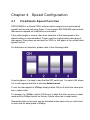
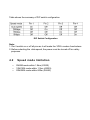
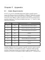
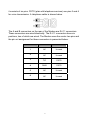
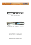
1
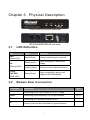
User’s Manual
VDSL CO / CPE Modem
Model No.: SP3501AM/SP3501AS
http://www.micronet.info
Table of Contents
Chapter 1 Introduction................................................................................. 1
1.1 Package Contents ............................................................................ 1
1.2 Key Features .................................................................................... 1
Chapter 2 Installation................................................................................... 3
2.1 Hardware Installation........................................................................ 3
2.2 Pre-installation Requirements .......................................................... 3
2.3 Cabling Requirements...................................................................... 3
2.4 Connecting the Modem .................................................................... 4
2.5 Connecting the RJ-11/RJ-45 Ports................................................... 4
Chapter 3 Physical Description .................................................................. 6
3.1 LED Definition .................................................................................. 6
3.2 Modem Rear Connectors ................................................................. 6
Chapter 4 Speed Configuration ................................................................. 7
4.1 Fixed/Auto Speed Function...............................................................7
4.2 Speed mode limitation...................................................................... 7
Chapter 5 Appendix ..................................................................................... 8
5.1 Cable Requirements......................................................................... 8
5.2 Specifications ................................................................................. 10
5.3 Troubleshooting.............................................................................. 11
5.4 Other Issues ................................................................................... 12
Chapter 1 Introduction
Micronet SP3501AM / SP3501AS delivers cost-effective and highperformance broadband access to multiunit building environments, such as
enterprise, campus, hospital, hotel, and telecom. With QAM-based 4-band
VDSL technology, the VDSL solution dramatically extends Ethernet and
supports 5M/15M/25Mbps symmetrical bandwidth over existing telephonegrade wiring up to 1.9/1.3/0.8KM.
1.1
Package Contents
Prior to the installation of the device, please verify the following items are in
the package:
y
y
y
y
y
y
1.2
y
y
y
y
y
y
y
VDSL Modem
¾ SP3501AM VDSL CO Modem
¾ SP3501AS VDSL CPE Modem
Quick Installation Guide
Manual CD
RJ-11 Cable
RJ-45 Cable
Power Adapter
Key Features
Compliant with ETSI, ITU, ANSI standards
Compliant with IEEE802.3 10BASE-T and IEEE802.3u 100BASE-TX
standards
Support 1 x RJ-11 VDSL port and 1 x RJ-11 Telephone port
Support 1 x RJ-45 Ethernet port of 10/100M
QAM-based 4-band VDSL
Data rate up to symmetrical bandwidth of 25Mbps
Wiring range up to 1.9KM
1
y
y
Fixed/Auto speed function for VDSL link
Built-in POTS/ISDN splitter (SP3501AM) for POTS/ISDN telephone
service
2
Chapter 2 Installation
2.1
Hardware Installation
This section describes how to install the Modem and establish network
connections. Users may install the Modem on any level surface. However,
please take note of the following minimum site requirements.
2.2
Pre-installation Requirements
Prior to the start of actual hardware installation, make sure users can provide
the right operating environment, including power requirements, sufficient
physical space, and proximity to other network devices that are to be
connected.
Verify the following installation requirements:
y
y
y
2.3
Power requirements: DC 5V/1A or above.
The Modem should be located in a cool dry place with at least 10cm
of space at the front and back for ventilation purpose.
Place the Modem out of direct sunlight, and away from heat sources
or areas with a high amount of electromagnetic interference.
Cabling Requirements
Before making any connections to the Modem, note the following rules:
Connection Type
Ethernet Port (RJ-45)
Cable Requirements
Maximum Length
y 100 Mbps: Cat 5 UTP
100 meters max for MUX
y 10 Mbps: Cat 3-4 UTP
or HUB to endpoint.
3
y 24-26 Gauge phone wiring
VDSL Port (RJ-11)
y Do not recommend 28 or y 15M/15M: 1.3km
y 25M/M: 800m
above Gauge
2.4
y
y
y
y
2.5
y 5M/5M: 1.9km
Connecting the Modem
The Modem provides a single Ethernet port, which support connection
through Ethernet operation.
Network devices attached to the Ethernet port must support autonegotiation, 10Base-T or 100Base-TX. Otherwise, the network device
must always operate at half duplex.
The RJ11 Line port is used to connect to the wall RJ-11 modular
socket (outlet), which is used to connect both master and slave
modem (Point to point solution).
The RJ11 Phone port of the Modem can be connected to a telephone
for users sharing the single telephone wire for making calls and
accessing the internet simultaneously.
Connecting the RJ-11/RJ-45 Ports
4
y
y
y
y
y
y
The Modem’s RJ-11 ports are easy-to-use and do not require
installation of additional wiring. Every RJ-11 modular phone jack in the
home can become a port on the LAN.
Networking devices can be installed on a single telephone wire that
can span within 1.9km or 800m (depend on speed) between the two
farthest points.
SP3501AM/S Modem has embedded Splitter between every VDSL
side (Line) and POTS (Phone) side. It permits user to deliver
broadband service on the same lines as Plain Old Telephone Service
(POTS), PBX, ISDN traffic and VDSL Signal.
When inserting a RJ-11 plug, be sure the tab on the plug clicks into
position to ensure that it is properly seated.
Do not plug a RJ-11 phone jack connector into the Ethernet port (RJ45 port). This may damage the modem. Instead, use only twisted-pair
cables with RJ-45 connectors that conform to Ethernet standard.
Make sure that the cables are all connected before powering on
devices.
5
Chapter 3 Physical Description
SP3501AM/SP3501AS front view
SP3501AM/SP3501AS rear view
3.1
LED Definition
LED
Status
Operation
PWR
(Power LED)
Steady Green
Device is powering on or reset ok
Steady Green
Lights up steadily to show good
linkage
Flashing Green
Flashing to show data transmission
Steady Green
Lights up steadily to show good
linkage at 5M/15M/25Mbps
Eth
(Ethernet LED)
5/15/25
LINE SPD
(VDSL LED)
3.2
Modem Rear Connectors
Connectors
Description
Type
Line
Connecting to the VDSL Modem via a RJ-11 cable
RJ-11
Phone
Connecting to the telephone, Fax or ISDN modem
RJ-11
Ethernet
Connecting to an Ethernet network device
RJ-45
FG
Frame ground can be connected to a ground bus bar
6
Chapter 4 Speed Configuration
4.1
Fixed/Auto Speed Function
SP3501AM/S is a 4-band VDSL solution which supports auto and manual
speed function and real plug & play. It can support 5M/15M/25M symmetrical
data service depend on installation environment.
If the cable length is unsure, then auto selection of the data speed at the
default setting is recommended. Power must be unplug before changing of
data speed, then power on and wait for VDSL to link again at the correct data
speed function.
For definitions of selectors, please refer to the following table:
At quick glance, it is easy to see that the DIP switch pin 1 is switch ON where
it is in auto-speed and that is also the default mode.
To set the data speed to 25Mbps simply switch ON pin 2 while the other pins
are in reset mode.
To change it to 15Mbps, switch ON the pin 3 while the other pins are in reset
mode and for 5Mbps switch on the pin 4 while other are in reset mode.
Remember that no two pins can be activated at the same time or it will result
in error and for data speed of 5Mbps.
Table shows the summary of DIP switch configuration.
DIP Switch Configuration
Note:
1. Don’t switch on or off all pins as it will make the VDSL modem functionless.
2. Before selecting the data speed, the power must be turned off for safety
purposes.
4.2
y
y
y
Speed mode limitation
5M/5M mode within 1.9km (6333ft)
15M/15M mode within 1.3km (4333ft)
25M/25M mode within 800m (2666ft)
Chapter 5 Appendix
5.1
Cable Requirements
A CAT 3, 4 or 5 UTP (unshielded twisted pair) cable is typically used to
connect the Ethernet device to the Modem. A 10Base-T cable often consists
of four pairs of wires, two of which are used for transmission. The connector
at the end of the 10Base-T cable is referred to as an RJ-45 connector and it
consists of eight pins. The Ethernet standard uses pins 1, 2, 3 and 6 for data
transmission purposes.
PIN
MNEMONIC
Function
1
TX+
Ethernet differential Transmit signal(+)
2
TX-
Ethernet differential Transmit signal(-)
3
RX+
Ethernet differential receive signal(+)
4
NC
Unused
5
NC
Unused
6
RX-
Ethernet differential receive signal(-)
7
NC
Unused
8
NC
Unused
Standard telephone wire of any gauge or type-flat, twisted or quad is used to
connect the Modem to the telephone network. A telephone cable typically
consists of three pairs of wires, one of which is used for transmission. The
connector at the end of the telephone cable is called an RJ-11 connector and
8
it consists of six pins. POTS (plain old telephone services) use pins 3 and 4
for voice transmission. A telephone cable is shown below.
The A and B connectors on the rear of the Modem are RJ-11 connectors.
These connectors are wired identically. The RJ-11 connectors have six
positions, two of which are wired .The Modem uses the center two pins and
the pin out assignment for these connectors is presented below.
PIN
MNEMONIC
Function
1
NC
Unused
2
NC
Unused
3
TIP
POTS
4
RING
POTS
5
NC
Unused
6
NC
Unused
9
5.2
Specifications
Model
Standards
SP3501AM
z
z
Interface
z
z
z
Distance
z
z
z
Features
UPnP
z
z
z
z
z
z
z
z
z
Dimension
Data Rate 5M/5M: up to 1.9km
Data Rate 15M/15M: up to 1.3km
Date Rate 25M/25M: up to 800m
z
z
Power Supply
1 X RJ-45 10/100Mbps Ethernet port
1 X RJ-11 connector for telephone connection
1 X RJ-11 connector for EoVDSL
z
z
Flow Control
IEEE802.3 10BASE-T and IEEE802.3u 100BASE-TX
standards
ETSI, ITU and ANSI standards
POTS/ISDN voices pass through
4 wires phone set pass through
Compatibility with xDSL, ISDN (2B1Q/4B3T).
Surge protection
Long packet size up to 1536 bytes
Auto MDI/MDIX and auto negotiation on Ethernet port
Fixed/Auto speed function and full duplex on VDSL port
Built-in splitter (SP3501AM)
z
z
VDSL Frequency
Spectrum
SP3501AS
SP3501AM:
¾
Transmitter: 900 KHz ~ 3.9MHz
Receiver: 4MHz & 7.9MHz
¾
SP3501AS:
Transmitter: 4MHz ~ 7.9MHz
¾
Receiver: 900 KHz ~ 3.9M
¾
IEEE802.3x for Full Duplex
Back Pressure for Half Duplex
Input: AC 85-240 volts/50-60Hz
Output: DC 5V. 1A or above
95 x 110 x 24 mm
10
5.3
Troubleshooting
y Symptom: Power indictor does not light up (Green).
¾ Causes: Defective external power supply.
¾ Solution: Check the power plug by attaching with a functioning
one. Check the power cord with other devices. If both tests fail,
have the power supply replaced by qualified distributor.
y
Symptom: Link indicator does not light up (Green).
¾ Causes: Network interface, network cable or switch port may be
faulty.
¾ Solution:
1. Power off and reconnect the VDSL modem.
2. Verify attached network devices are powered on.
3. Verify the cables are connected properly on both ends.
4. Verify the proper cable is used and the distant does not
exceed the specified limit.
5. Phone wire must be connected between SP3501AM and
SP3501AS prior to powering on of devices.
6. Replace the defective cable or modem if necessary.
y
Symptom: VDSL Link cannot be established.
¾ Causes: VDSL auto speed failure. Otherwise the phone cable
length is over specification limit of 1.9km or not a 24 gauge phone
wire with twist pair.
¾ Solution:
1. Please check phone cable must be 24-gauge with twist pair
and without rust, and the length is not over 1.9km.
2. Phone wire must be connected between SP3501AM and
SP3501AS prior to powering on of devices.
y
Symptom: VDSL always link on 5M/5M speed mode at short phone
cable.
¾ Causes: VDSL auto speed is not functioning.
¾ Solution: Turn the power off and reconnect the cables between
both devices. The devices will run auto speed function when it
powers back on.
11
y
5.4
Symptom: S0 bus from an NTBA - data works, but ISDN telephone
does not.
¾ Solution: Connect according to the following chart for connecting
CO and CPE with NTBA.
Other Issues
Power and Cooling Problems
If the POWER indicator does not turn on when the power cord is plugged in,
users may have a problem with the power outlet, power cord, or internal
power supply as explained in the previous section. However, if the unit
powers off after running for a while, check for loose power connections,
power losses or surges at the power outlet, and verify that the fan on back of
the unit is unobstructed and running prior to shutdown. If users still cannot
isolate the problem, then the internal power supply may be defective.
Installation
Verify that all system components have been properly installed. If one or
more components appear to be malfunctioning (e.g., the power cord or
network cabling), test in an alternate environment where users are certain
that all other components are functioning properly.
12
Transmission Mode
The default method of selecting the transmission mode for RJ-45 port is
10/100 Mbps and for RJ-11 port is 5/15/25Mbps. Therefore, if the link signal
is disrupted (e.g., by unplugging the network cable and plugging it back in
again, or by resetting the power), the port will try to establish communications
with the attached device via auto-negotiation. If auto-negotiation fails, then
communications are set to half duplex by default. Based on this type of
industry-standard connection policy, if users are using a full-duplex device
that does not support auto-negotiation, communications can be easily lost
whenever the attached device is reset or experiences a power fluctuation.
The best way to resolve this problem is to upgrade these devices to a version
that support Ethernet and VDSL.
Physical Configuration
If problems occur after altering the network configuration, restore the original
connections, and try to track the problem down by implementing the new
changes, one step at a time. Ensure that cable distances and other physical
aspects of the installation do not exceed recommendations.
System Integrity
As a last resort verify the switch integrity with a power-on reset. Turn the
power to the switch off and then on several times. If the problem still persists
and users have completed all the preceding diagnoses, then contact an
authorized dealer.
13