1
alféa hybrid duo gas
Air/water heat pump
with integrated gas burner,
split, 2 services
Outdoor unit
AOYA 30 LBTL
Document n° 1485-7 ~ 08/01/2013
FR
EN
ES
PT
IT
DE
EN
Hydraulic unit
024200
AOYA 45 LBTL
AOY 54 LJBYL
WOYK112LCT
WOYK140LCT
WOYK160LCT
Installation and
commissioning
instructions
for professionals
to be kept by the user
for future reference
atlantic-comfort.com
7KHVSHFL¿FDWLRQVRIWKLVHTXLSPHQWPD\
EHPRGL¿HGZLWKRXWSULRUQRWLFH
1RQFRQWUDFWXDOGRFXPHQW
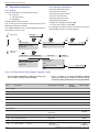
Heat pump alféa hybrid duo gas
The following are required for the installation of this appliance:
" TXDOL¿HG SHUVRQQHO FHUWL¿HG DV FDSDEOH RI KDQGOLQJ UHIULJHUDWLQJ ÀXLGV DFFRUGLQJ WR
environmental legislation ).
" a heating engineer.
&HUWL¿FDWHRIFRQIRUPLW\
7KHXVHRIDJDVERLOHUUHTXLUHVD&HUWL¿FDWHRI&RQIRUPLW\VLJQHGE\ORFDODXWKRULWLHV
-2-
Installation and commissioning instructions "1485 - EN"
Heat pump alféa hybrid duo gas
Contents
Presentation of the equipment . . . . . . . . . . . . . . . . . . . . . . . . . 5
Packaging . . . . .
Optional equipment
Scope . . . . . . .
'H¿QLWLRQV . . . . .
.
.
.
.
.
.
.
.
.
.
.
.
.
.
.
.
.
.
.
.
.
.
.
.
.
.
.
.
.
.
.
.
.
.
.
.
.
.
.
.
.
.
.
.
.
.
.
.
.
.
.
.
.
.
.
.
.
.
.
.
.
.
.
.
.
.
.
.
.5
.5
.5
.5
General characteristics . . . . . . . . . . . . . . . . 6
Description. . . . . . . . . . . . . . . . . . . . . . 11
Operating principle . . . . . . . . . . . . . . . . . 13
Installation . . . . . . . . . . . . . . . . . . . . . . . . . . . . . . . . . . . 15
Installation and maintenance rules . . . . . . . .
Unpacking and reserves . . . . . . . . . . . . . .
Reception . . . . . . . . . . . . . . . . . .
Handling . . . . . . . . . . . . . . . . . .
Containment of refrigerant circuits . . . . .
Accessories supplied . . . . . . . . . . . .
Positioning . . . . . . . . . . . . . . . . . . . . .
Installing the outdoor unit . . . . . . . . . . . . .
Installation precautions . . . . . . . . . . .
Fitting the outdoor unit . . . . . . . . . . .
Connecting the condensate evacuation pipe
Installing the hydraulic module . . . . . . . . . .
Room where to install . . . . . . . . . . . .
Chimney evacuation pipe, B23, B23P . . . . . . .
Chimney connection pipe, B23, B23P . . . . . . .
Room-sealed connection pipe C13, C33, C53 . .
Concentric horizontal room-sealed pipe
(C13 type). . . . . . . . . . . . . . . . . .
Concentric vertical pipe (C33 type) . . . . .
Separate air intake
and smoke evacuation pipes (C53 type) . .
Refrigerant connections . . . . . . . . . . . . . .
Rules and precautions . . . . . . . . . . .
Refrigerating connections. . . . . . . . . .
Flaring . . . . . . . . . . . . . . . . . . .
Forming the refrigerant tubes . . . . . . . .
&RQQHFWLQJWKHÀDUHFRQQHFWLRQV . . . . . .
Filling the installation with gas . . . . . . . . . . .
Commissioning procedure . . . . . . . . .
Sealing test . . . . . . . . . . . . . . . . .
Additional charge
(outdoor three phase unit) . . . . . . . . .
&ROOHFWWKHUHIULJHUDQWÀXLGLQ
the outdoor unit . . . . . . . . . . . . . . .
Installation and commissioning instructions "1485 - EN"
.
.
.
.
.
.
.
.
.
.
.
.
.
.
.
.
15
15
15
15
15
15
16
16
16
18
18
19
19
20
20
21
. 21
. 23
.
.
.
.
.
.
.
.
.
.
23
25
25
25
26
26
26
28
28
29
Connecting the heating circuit and
the domestic circuit . . . . . . . . . . . . . . . .
General . . . . . . . . . . . . . . . . . . .
Rinsing the installation . . . . . . . . . . .
Filling and draining the installation . . . . .
&RQQHFWLRQWRDQXQGHUÀRRUKHDWLQJFLUFXLW .
Connection to a fan coil circuit . . . . . . .
Connection to the domestic circuit . . . . .
Condensate evacuation . . . . . . . . . . . . . .
Gas change . . . . . . . . . . . . . . . . . . . .
Connection of the fuel supply . . . . . . . . . . .
Electrical connections . . . . . . . . . . . . . . .
Characteristics of the electrical power supply
General remarks on the electrical connections
Overall view of the electrical connections .
Cross section of the cable and protection rating
Electrical connections on outdoor unit side
(single phase model) . . . . . . . . . . . .
Electrical connections on outdoor unit side
(three phase model) . . . . . . . . . . . .
Electrical connections on
the hydraulic module side. . . . . . . . . .
Outdoor sensor . . . . . . . . . . . . . . . . . .
Ambient sensor and/or central ambient unit . . . .
Installing an ambient sensor . . . . . . . .
Installing a central ambient unit . . . . . .
.
.
.
.
.
.
.
.
.
.
.
.
.
.
.
31
31
31
32
32
32
32
32
33
33
34
34
34
35
35
. 37
. 37
.
.
.
.
.
38
40
40
40
40
. 30
. 30
-3-
Heat pump alféa hybrid duo gas
Commissioning. . . . . . . . . . . . . . . . . . . . . . . . . . . . . . . . . 42
Checks before commissioning. . . . . . . . . . .
Hydraulic circuit: . . . . . . . . . . . . . .
Gas circuit: . . . . . . . . . . . . . . . . .
Electric circuit: . . . . . . . . . . . . . . .
Commissioning the heat pump . . . . . . . . . .
Starting the gas generator to check the combustion.
Heating installation with radiators. . . . . .
Heating installation with
1XQGHUÀRRUKHDWLQJFLUFXLW . . . . . . . . .
.
.
.
.
.
.
.
42
42
42
42
42
43
43
Setting the combustion parameters during a gas check
Heating installation with radiators. . . . . .
Heating installation with
1XQGHUÀRRUKHDWLQJFLUFXLW . . . . . . . . .
&RQ¿JXUDWLRQRIWKHDPELHQWVHQVRU7 . . . . .
&RQ¿JXUDWLRQRIWKHFHQWUDODPELHQWXQLW7RU7
. 44
. 44
. 44
. 45
. 45
. 43
Regulation . . . . . . . . . . . . . . . . . . . . . . . . . . . . . . . . . . . 46
The user interface, the central ambient unit (option)
and the ambient sensor (option) . . . . . . . . . . .
Description of the display . . . . . . . . . . . . . .
Water logic . . . . . . . . . . . . . . . . . . . . . .
Setting . . . . . . . . . . . . . . . . . . . .
46
48
48
48
Regulation parameters . . . . .
General . . . . . . . . . .
Setting the parameters . .
List of the function lines
(settings, diagnosis, state)
. . . . . . . . . . 50
. . . . . . . . . . 50
. . . . . . . . . . 50
. . . . . . . . . . 50
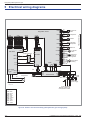
Electrical wiring diagrams . . . . . . . . . . . . . . . . . . . . . . . . . . . 62
Fault diagnostic . . . . . . . . . . . . . . . . . . . . . . . . . . . . . . . . 67
Fault display on the hydraulic module . . . . . . . . 67
Faults displayed on the outdoor unit
single phase model . . . . . . . . . . . . . . . . . 70
Faults displayed on the outdoor unit
three phase model . . . . . . . . . . . . . . . . . . 71
Display information . . . . . . . . . . . . . . . . . 72
Servicing of the installation . . . . . . . . . . . . . . . . . . . . . . . . . . 73
Servicing of the gas heat exchanger
Checking the hydraulic circuit . . . .
Servicing the evacuation pipe . . . .
Servicing the tank . . . . . . . . . .
Draining the hot water tank . .
Descaling . . . . . . . . . . .
.
.
.
.
.
.
.
.
.
.
.
.
.
.
.
.
.
.
.
.
.
.
.
.
.
.
.
.
.
.
.
.
.
.
.
.
.
.
.
.
.
.
.
.
.
.
.
.
73
73
74
74
74
74
Checking the outdoor unit . . . . . . . . . . . . . . 74
Checking the electrical circuit . . . . . . . . . . . . 74
Checking the combustion parameters . . . . . . . . 74
Maintenance . . . . . . . . . . . . . . . . . . . . . . . . . . . . . . . . . . 75
Draining the hydraulic module . . . . . . . . . . . . 75
Directional valve . . . . . . . . . . . . . . . . . . . 75
ACI check . . . . . . . . . . . . . . . . . . . . . . 75
9DOXHVWREHJLYHQWRWKHXVHU . . . . . . . . . . . . . . . . . . . . . . . . . 75
Start-up procedure . . . . . . . . . . . . . . . . . . . . . . . . . . . . . . . 76
Commissioning assistance "check list" . . . . . . . 76
Before starting . . . . . . . . . . . . . . . . 76
Start-up . . . . . . . . . . . . . . . . . . . . 77
-4-
&RQ¿JXUDWLRQ¿OH. . . . . . . . . . . . . . . . . . . 78
Technical commissioning instructions . . . . . . . . 79
Installation and commissioning instructions "1485 - EN"
Heat pump alféa hybrid duo gas
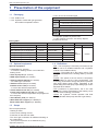
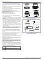
1 Presentation of the equipment
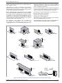
1.1
Packaging
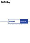
1 box: Choice of connection pipe.
1 box: Outdoor unit.
Concentric...
1 box: Hydraulic module with gas generator
and outdoor temperature sensor.
C13
... horizontal turbo pipe (073 224).
... vertical turbo pipe black (073 226 or 074 031).
C33
... vertical turbo pipe ocher (073 226 or 074 032).
Adaptor...
C53 1
Separate pipe adaptor 80 (073 428).
B23
B23P 2
Chimney adaptor 80 (073 295).
2
&RQ¿JXUDWLRQSRVVLEOHRQO\LQERLOHUURRP
For B23 and B23P connection, the chimney adaptors
provided must be used.
1
2
3DLULQJWDEOH
Heat pump
Model
Outdoor unit
Export code
Hydraulic module
Ref.
Code
alféa hybrid duo gas 10 single phase
522181
AOYA 30 LBTL
700730
alféa hybrid duo gas 13 single phase
522182
AOYA 45 LBTL
700845
alféa hybrid duo gas 16 single phase
522183
AOY 54 LJBYL
700054
alféa hybrid duo gas 11 three phase
522184
WOYK 112 LCT
700118
alféa hybrid duo gas 14 three phase
522185
WOYK 140 LCT
700143
alféa hybrid duo gas 16 three phase
522186
WOYK 160 LCT
700163
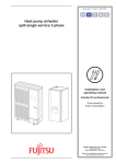
1.2
Optional equipment
Optional equipment
2 circuit kit (ref. 074012)
WRFRQQHFWKHDWLQJFLUFXLWVRUDQXQGHUÀRRU
heating circuit.
Class A pump kit (ref. 074013)
DHW expansion kit (ref. 074026)
Chimney adaptor 80-125 (ref. 073423).
- for a B23* type connection
Ambient sensor T37 (ref. 075308),
Ambient sensor T55 (ref. 073951)
- to correct the ambient temperature.
Central ambient unit T75 (ref. 073954),
Central radio ambient unit T78 (ref. 074061)
- to correct the ambient temperature and programme
the heat pump.
Anti-vibration pads (ref. 523574).
1.4
Ref.
MH
3922401
Code
024200
'H¿QLWLRQV
- Split : The heat pump is formed by two elements (an
outdoor unit to be installed outdoors and a hydraulic
module to be installed indoors).
- Air/water: The outdoor air is the energy source. This
energy is transmitted to the heating water by the heat
pump.
- Inverter: The speed of the fan and the compressor
are modulated to suit the heat requirements. This
technology economises energy and permits operation
with single phase power supply, regardless of the
power rating of the heat pump, by avoiding high current
demands when started.
- COP FRHI¿FLHQW RI SHUIRUPDQFH WKLV LV WKH UDWLR
between the energy transmitted to the heating circuit
and the electrical energy consumed.
- Hybrid: the hydraulic module operates with dual
energy (air/water heat pump and built in gas boiler).
:KLWH39&ÀRRUVXSSRUW (ref. 809532) or
%ODFNUXEEHUÀRRUVXSSRUW (ref. 809536).
1.3
Scope
This heat pump allows:
- Heating in winter,
- Control of two heating circuits*,
- Production of domestic hot water,
- The use of gas combustion for additional heating on
the coldest days.
* : These options require the use of additional kits (see §
"Optional equipment").
Installation and commissioning instructions "1485 - EN"
-5-
Heat pump alféa hybrid duo gas
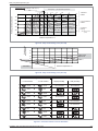
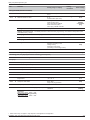
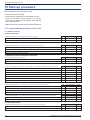
1.5
General characteristics
Model denomination
10
DOIpDK\EULGGXRJDV
Gas category
13
16
11 three
14 three
16 three
II2Esi3P
FR
II2H3P
CH - CZ - ES - IT - LT - PT - SK
DK - EE - FI - IT - SE
I2H
LU - DE
I2E
NOx class
5
Nominal heating performances (T° outdoor/T° start)
&DORUL¿FSRZHU
&&XQGHUÀRRUKHDWLQJ
kW
9.75
13.20
15.50
10.80
13.50
15.17
&&XQGHUÀRRUKHDWLQJ
kW
8.10
10.30
12.15
10.80
13.00
13.50
&&/7UDGLDWRU
kW
7.97
10.30
13.03
10.10
12.60
13.00
&&/7UDGLDWRUV
kW
6.96
9.25
10.78
10.02
12.50
13.00
&&XQGHUÀRRUKHDWLQJ
kW
2.50
3.30
4.31
2.51
3.20
3.70
&&XQGHUÀRRUKHDWLQJ
kW
3.52
3.96
4.86
4.28
5.18
5.40
&&/7UDGLDWRUV
kW
2.61
3.25
4.54
3.01
3.81
4.00
&&/7UDGLDWRUV
kW
3.40
4.20
5.26
4.63
6.00
6.37
3.90
4.00
3.60
4.30
4.22
4.10
$EVRUEHGSRZHU
&RHI¿FLHQWRISHUIRUPDQFH&23&&
*DVERLOHUSHUIRUPDQFHV
&ODVVDFFRUGLQJWRRXWSXWGLUHFWLYH&((
kW
&RQGHQVDWLRQ
&ODVVDFFRUGLQJWR57
kW
&RQGHQVDWLRQ
1RPLQDOFDORUL¿FÀRZUDWH
kW
24.7
1RPLQDOXVHIXOSRZHUKHDWLQJKRWZDWHU
kW
24 / 24
1RPLQDOXVHIXOSRZHULQFRQGHQVDWLRQUHWXUQ&
kW
24.8
0LQLPXPXVHIXOSRZHU&
kW
5.5
0LQLPXPFDORUL¿FÀRZUDWH
kW
5.7
Electrical characteristics
9ROWDJH+=
V
230
230
230
400
400
400
0D[LPXPFXUUHQWRIWKHDSSOLDQFH
A
17
1RPLQDOFXUUHQW
A
11.7
20
26
8,5
9.5
10.5
16.7
20.6
3,7
4.8
5.5
E\WKHIDQ
W
103
2 x 10³
2 x 10³
2 x 10⁴
2 x 10⁴
2 x 10⁴
E\WKHKHDWÀRZSXPSFLUFXODWRUVPD[JDVJHQHUDWRU
W
5865
6555
7245
$FWXDOSRZHUDEVRUEHG
132 / 93
0D[LPXPSRZHUDEVRUEHG
E\WKHRXWGRRUXQLW
W
3910
4600
5980
E\WKHK\GUDXOLFPRGXOH
W
244
EDU
3
+\GUDXOLFFLUFXLW
0D[RSHUDWLQJSUHVVXUH306
)ORZUDWHRIWKHK\GUDXOLFFLUFXLWDW&ǻW&QRPLQDOFRQGLWLRQV
- 0LQÀRZUDWH
l/h
1000
1380
1670
1170
1460
1650
- 0D[ÀRZUDWH
l/h
2100
2700
3300
2340
2920
3290
2500
2500
2500
5 / 15
5 / 15
5 / 15
([SDQVLRQYHVVHO
OLWUH
18
'LDPHWHUVRIWKHJDVSLSHV
LQFK
5/8
'LDPHWHUVRIWKHOLTXLGSLSHV
LQFK
)DFWRU\FKDUJHRIUHIULJHUDWLQJ5$
g
0D[RSHUDWLQJSUHVVXUH
EDU
3LSHOHQJWKPLQPD[ m
Refrigerating circuit
(1)
(2)
5HIULJHUDQW5$LQFRPSOLDQFHZLWKVWDQGDUG1)(1
)DFWRU\FKDUJHRIUHIULJHUDWLQJÀXLG5$
-6-
3/8
2100
3350
3400
41,5
5 / 20
5 / 20
5 / 20
7DNLQJ LQWR DFFRXQW WKH SRWHQWLDO DGGLWLRQDO FKDUJH RI UHIULJHUDWLQJ ÀXLG
5$VHHSDJH
Installation and commissioning instructions "1485 - EN"
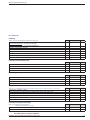
Heat pump alféa hybrid duo gas
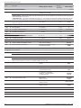
DOIpDK\EULGGXRJDV
Model denomination
0D[SLSHOHQJWK 0D[JUDGLHQW
m
10
13
16
11 three
14 three
16 three
- / 20
- / 20
- / 20
20 / 20
20 / 20
20 / 20
99
99
99
Domestic hot water tank
&DSDFLW\RIGRPHVWLFKRWZDWHUWDQN
OLWUH
120
0D['+:FLUFXLWXVDJHSUHVVXUH306
EDU
7
6SHFL¿F'+:ÀRZUDWHDW'7.'
l/mn
20
0D[WHPSHUDWXUH
°C
65
Miscellaneous
:HLJKWRIWKHRXWGRRUXQLW
kg
64
98
105
:HLJKWRIWKHK\GUDXOLFPRGXOHHPSW\ZLWKZDWHU
kg
135 / 278
+\GUDXOLFPRGXOHZDWHUFDSDFLW\
OLWUH
23
$FRXVWLFSRZHU DFFRUGLQJWR(1
K\GPRGXOHWKHUPRG\QDPLFPRGH
G%$
46
1RLVHOHYHODWPRXWGRRUXQLW
G%$
41
40
44
39
41
42
$FRXVWLFSRZHU LQFRPSOLDQFHZLWK(1RXWGRRUXQLW
G%$
68
71
71
66
68
69
Heating operating limits
0LQPD[RXWGRRUWHPSWKHUPRG\QDPLFPRGH
°C
0D[ZDWHUWHPSHUDWXUHWKHUPRG\QDPLFPRGH
°C
0D[ÀRZZDWHUWHPSHUDWXUHIRUVWDUWRIKHDWLQJ
°C
-15 / +24 -15 / +24 -15 / +24 -25 / +35 -25 / +35 -25 / +35
52
52
52
60
60
60
80
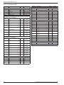
*DVERLOHUFKDUDFWHULVWLFV
*DVÀRZUDWHLQFRQWLQXRXVRSHUDWLRQ&PEDU
1DWXUDOJDV*PEDU
m3/h
2.55
1DWXUDOJDV*PEDU
m3/h
2.93
3URSDQH*PEDU
m /h
1.00
3
DiaphragmJDVYDOYHRXWOHW
1DWXUDOJDV*PEDULWHPGLDPHWHU
LWHP
20 - 6.5 mm
1DWXUDOJDV*PEDULWHPGLDPHWHU
LWHP
none
SURSDQH*PEDULWHPGLDPHWHU
LWHP
FRQLFDOPP
&RPEXVWLRQSURGXFWV
6PRNHWHPSHUDWXUHPLQLPXPPD[LPXP
°C
35 / 70
6PRNHPDVVÀRZUDWHPLQLPXPPD[LPXP
g/s
2.87 / 11.9
&RQFHQWULFKRUL]RQWDORUYHUWLFDOURRPVHDOHGWXUERSLSH
6PRNHDLUDVSLUDWLRQWXEHGLDPHWHU&&
mm
80 / 125
6PRNHWXEHGLDPHWHU&
mm
80
0D[LPXPDXWKRULVHGVWUDLJKWOLQHOHQJWKH[FOXGLQJWHUPLQDO
m
11
/RVVRIFKDUJHE\HOERZ
m
1 / 0.5
&RPSDWLEOHWHUPLQDODQGPDWHULDO
8%%,1.328-28/$7
:LWKFKLPQH\DGDSWRU
6PRNHWXEHGLDPHWHU
mm
80
2SWLPXPORZSUHVVXUHLQWKHFKLPQH\W\SH%
3D
15
0D[SUHVVXUHDYDLODEOHRQWKHHYDFXDWLRQQR]]OHW\SH%3
3D
70
0D[SUHVVXUHDYDLODEOHRQWKHHYDFXDWLRQQR]]OHW\SH%3
3D
6RXQGSUHVVXUHOHYHODW[PIURPWKHDSSOLDQFHPIURPWKHJURXQG
IUHH¿HOGGLUHFWLYLW\
7KHDFRXVWLFSRZHULVDPHDVXUHPHQWPDGHLQWKHODERUDWRU\RIWKHSRZHU
RIWKHQRLVHHPLWWHGEXWFRQWUDU\WRWKHQRLVHOHYHOLWGRHVQRWFRUUHVSRQGWR
WKHPHDVXUHPHQWRIZKDWLVIHOW
:HRQO\JXDUDQWHHWKHFRUUHFWRSHUDWLRQRIWKHJDVJHQHUDWRUZLWKWKH
URRPVHDOHGWXUERSLSHGHVFULEHGEHORZ
8EELQNVXSSOLHV.
8%%,1.52/8;&21'(16$7,21*$6ZLWKSRO\SURS\OHQH337/
LQWHUQDOSLSH
52/8;YHUWLFDOWHUPLQDO*
52/8;&21+5YHUWLFDOWHUPLQDO)9
5pQROX[V\VWHPIRUDGDSWDWLRQWRWKHH[LVWLQJHYDFXDWLRQSLSH
3RXMRXODWVXSSOLHV.
'XDOLVKRUL]RQWDOFRQGHQVDWLRQWHUPLQDO67+*33RXMRXODW
'XDOLVYHUWLFDOFRQGHQVDWLRQWHUPLQDO679*33RXMRXODW
&RQFHQWULFSLSHVRUPPDQGOHQJWKDGMXVWDEOH
WRPPDQGHOERZV
7KHXVHRIDOXPLQLXPFRQQHFWLRQSLSHVLVSURKLELWHG
Installation and commissioning instructions "1485 - EN"
-7-
Heat pump alféa hybrid duo gas
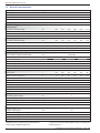
" 2XWGRRUXQLW
K\EULGGXRJDVVLQJOHSKDVHPRGHO
650
AIR
370
opening (Ø 20)
Orifice Flow
d’écoulement
44 holes
trous Ø 10)
Bottom
view
Vue
de dessous
31
330
12
900
77
830
AIR
5/8”
196
21
3/8”
99
9
147
Front
view
Vue
de face
170
400
Side view
Vue de côté
view
VueTop
de dessus
650
" 2XWGRRUXQLW
K\EULGGXRJDVVLQJOHSKDVHPRGHO
K\EULGGXRJDVVLQJOHSKDVHPRGHO
Air
370
Orifice
d’écoulement
Flow
opening (Ø 20)
31
330
12
Bottom
view
Vue
de dessous
trous Ø 10)
4 4holes
900
77
Air
1290
Air
3/8”
5/8”
99
21
196
9
147
Front
view
Vue
de face
170
400
Side
view
Vue de
côté
view
Vue Top
de dessus
¿JXUHDimensions in mm
-8-
Installation and commissioning instructions "1485 - EN"
Heat pump alféa hybrid duo gas
650
" 2XWGRRUXQLW
K\EULGGXRJDVWKUHHSKDVHPRGHO
K\EULGGXRJDVWKUHHSKDVHPRGHO
K\EULGGXRJDVWKUHHSKDVHPRGHO
370
Air
Drain hole (ø 20)
31
330
12
4 holes (ø 10)
Bottom view
900
Air
1290
Air
9
21
400
Front view
Side view
Top view
¿JXUHDimensions in mm
" +\GUDXOLFPRGXOH
598
Chimney connection
273
179
268
130
199
49,3
*DV[0
+HDWLQJUHWXUQ
26x34 M
+HDWLQJÀRZ[0
1828
1729
30
1800
'+:[0
&ROGZDWHU[0
1229
832
794
199
271,5
Dimensions of the hydraulic module, see
¿JXUHSDJH.
163
647
55
Rear view
Side view
¿JXUHDimensions in mm
Installation and commissioning instructions "1485 - EN"
-9-
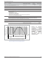
Heat pump alféa hybrid duo gas
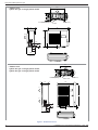
mbar
1 mbar = 10 mmCE = 100 Pa
1 mbar = 10 mmCE = 100 Pa
800
700
vitesse
600
2
Outdoor sensor QAC34
3
43907
500
1
N&
10000
400
2490
300
1000
200
100
338
0
1
1,2
1,4
1,6
1,8
2
2,2
-50
2,4
-25
0
25
50
75
°C
3
m /h
¿JXUH+\GUDXOLFSUHVVXUHVDQGÀRZUDWHVDYDLODEOH
Heat pump return sensor
+HDWSXPSÀRZVHQVRU
32500
30000
27500
25000
22500
20000
17500
N&
15000
12500
10000
7500
5000
2500
0
0
10
20
30
40
50
60
70
80
90
100 °C
¿JXUHOhmic value of the sensors (hydraulic module)
2KPLFYDOXHNȍ
10000
- Compressor
- Discharge
- Condensation
1000
- Outdoor
100
- Evaporator outlet
- Evaporator middle
- Compressor carter
10
1
-20 -10 0 10 20 30 40 50 60 70 80 90 100 110 120 130
Temperature °C
¿JXUHOhmic value of the sensors (outdoor unit)
- 10 -
Installation and commissioning instructions "1485 - EN"
Heat pump alféa hybrid duo gas
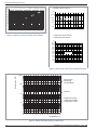
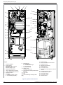
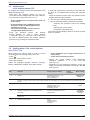
1.6
Description
" K\EULGGXRJDV
" K\EULGGXRJDVK\EULGGXRJDV
2
1
2
1
3
4
3
5
4
5
7
7
8
8
9
9
13
12
6
10
11
/HJHQG
1 - High performance impeller and low noise level.
12
13
6
10
11
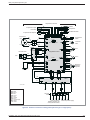
2 - Electrical motor with variable "inverter" operation.
" K\EULGGXRJDV
3-phase
3 - "Inverter" command module.
4 - Control LEDs and buttons.
WO*K1**LCT
5 - Connection terminal blocks
(power supply and inter-connection).
1
3
6 - 6WRUDJHERWWOHIRUUHIULJHUDWLQJÀXLG
7 - Cycle inversion valve.
8 - Panels treated against corrosion.
4
9 - Electronic pressure regulator.
10 - "Inverter" compressor acoustically and thermally
insulated.
11 - Refrigerating connection taps
ÀDUHFRQQHFWRUZLWKSURWHFWLYHFRYHU
2
5
14
13
15
12 - Condensate basin with drain hole
9
13 - High performance exchange surface evaporator;
DQWLFRUURVLRQWUHDWHGK\GURSKLOLFDOXPLQLXP¿QV
and grooved copper tubes.
7
14 - Solenoid valve for injection of liquid.
11
15 - Electronic pressure regulator for injection of liquid.
6
16 - "Inverter" compressor acoustically and thermally
insulated with liquid injection port.
8
12
16
10
¿JXUHOutdoor unit devices
Installation and commissioning instructions "1485 - EN"
- 11 -
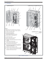
Heat pump alféa hybrid duo gas
1
4
10
5
2
9
12
26
13
9
14
24
6
25
15
16
3
16
7a
23
21
7b
22
11
8a
17
18
8b
8c
17
20
19
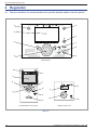
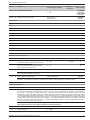
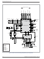
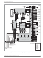
Legend:
1 - Chimney adaptor.
2 - Control panel:
Regulator / User interface,
On / off switch,
Pressure gauge, Light.
3 - Heat pump condenser.
4 - "Gas" refrigerating connector
5 - "Fluid" refrigerating connector
6 - Directional valve.
7 - Circulator
a - Heating (heating circuit),
b - Gas exchanger (CEG).
8 - Drainage tap
a - Heating body
b - Hot water exchanger
c - Hot water tank
9 - Manual drain tap.
10 - Safety valve,
Automatic drain tap.
11 - 18l expansion vessel (maintenance
position).
12 - Gas valve.
13 - Fan.
14 - Gas condensing exchanger Gaz
(EG)
3UHVVXUHÀDS
16 - Disconnectable no return valve
17 - Inspection trap
18 - Titanium anode (ACI).
19 - Adjustable feet
20 - Hot water sensor.
21 - Heat pump output sensor, common
sensor.
22 - Heat pump return sensor
23 - Condensation sensor.
24 - EG output sensor
25 - EG return sensor
26 - Smoke sensor.
¿JXUHHydraulic module devices
- 12 -
Installation and commissioning instructions "1485 - EN"
Heat pump alféa hybrid duo gas
1
3
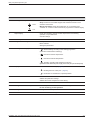
Legend:
1
2
3
4
5
5
2
- Regulator / User interface.
- On / off switch.
- ACI light.
- Pressure gauge.
- Safety light.
¿JXUH
Control panel
4
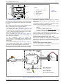
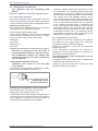
1.7
Operating principle
The heat pump transmits the energy in the outdoor air to
the home to be heated and the production of domestic
hot water.
The heat pump is formed of four main elements inside
ZKLFKDUHIULJHUDWLQJÀXLGFLUFXODWHV5$
- In the evaporator (item 13, ¿JXUH SDJH ):
The calories are taken from the outdoor air and
WUDQVPLWWHGWRWKHUHIULJHUDWLQJÀXLG$VLWVERLOLQJSRLQW
is low, it changes from the liquid state to the vapour
state, even when the weather is cold.
- In the compressor (item 10 or 16, ¿JXUHSDJH):
7KH YDSRULVHG UHIULJHUDWLQJ ÀXLG LV SUHVVXULVHG DQG
thus carries more calories.
- In
the
condenser
(item
3,
¿JXUH ):
7KH HQHUJ\ RI WKH UHIULJHUDWLQJ ÀXLG LV WUDQVPLWWHG WR
WKHKHDWLQJFLUFXLW7KHUHIULJHUDWLQJÀXLGUHWXUQVWRLWV
liquid state.
- In the pressure regulator (item 9 or 15, ¿JXUHSDJH):
7KHQ OLTXH¿HG UHIULJHUDWLQJ ÀXLG LV UHGXFHG WR ORZ
pressure and its initial temperature and pressure.
The heat pump has a regulator that controls the indoor
temperature based on the measurement of the outdoor
temperature, regulation by water logic. The ambient
sensor (optional) provides a corrective action to the
water logic.
The hydraulic module is equipped gas generator which
operates at the request of the regulator:
- to provide additional heating during the colder
periods,
- to reach the DHW comfort value
- to provide a relay during "Peak rate" days (load
shedding or EJP function).
Priority is given to the operation of the heat pump.
:KHQWKHKHDWSXPSLVQRWVXI¿FLHQWIRUWKHKHDWLQJWKH
gas generator automatically takes over.
/HDNSURRIW\SHDSSOLDQFH&&&
The new air needed for combustion is taken from
outside the horizontal or vertical terminal and is then
aspirated into the boiler through the pipes (concentric
or separate).
&KLPQH\W\SHDSSOLDQFH%%3
The new air needed for combustion is taken from the
room where the appliance is installed.
PAC
4 kW
Dt
Cn
$LUHQHUJ\
Ev
Heat produced
20 °C
Cp
COP 4
1 kW
Electric
HQHUJ\
consumed
PAC - Heat pump
Ev - Evaporator
Cp - Compressor
Cn - Condenser
Dt - Pressure regulator
¿JXUH2SHUDWLQJSULQFLSOHRIDKHDWSXPS
Installation and commissioning instructions "1485 - EN"
- 13 -
Heat pump alféa hybrid duo gas
Regulation functions
- The initial temperature of the heating circuit is
controlled by water logic.
- In function of an initial heating temperature, the power
of the outdoor unit is modulated via the "inverter"
compressor.
- Management of the supplementary heating.
- The daily timer programme allows comfort or reduced
ambient temperature periods.
- Switching between summer/winter operation is
automatic.
- Ambient sensor*: The ambient sensor provides a
corrective action to the water logic.
- Management of a 2nd heating circuit*.
- Domestic hot water: Hourly heating programme,
management of the comfort temperature and the
reduced temperature.
*When the heat pump is equipped with options and associated kits.
Protection functions
- Anti-legionella cycle for the domestic hot water.
- Tank anti-corrosion protection by titanium anode (ACI).
- Antifreeze protection for the installation, DHW, etc.
+\GUDXOLFSUHVVXUHPRQLWRULQJ
A pressure switch monitors the hydraulic pressure. If
the pressure is lower than:
- 0.5 bars: Safety
- 0.8 bars: Power reduction and information on the display.
Operating principle of the domestic hot water
'+:
DHW production takes priority over heating.
Two domestic hot water (DHW) temperatures may
be set: comfort temperature (line 1610 at 55 °C)
and reduced temperature (line 1612 at 40 °C).
The default DHW programme follows the hourly heating
programme with 1 hour's advance on start-up.
Depending on the parameter setting (1620), the comfort
temperature may be reached 24 hours / day or according
to the DHW programme.
The reduced temperature value may be useful to avoid
restarting the DHW too many times and for too long
through the day.
The production of domestic hot water (DHW) is started
when the temperature in the tank is 7°C below (setting
of line 5024) the reference value temperature.
The domestic hot water (DHW) is produced by the heat
pump and the boiler top-up.
A switching function of "reduced" to "comfort" is
available on the front panel of the user interface
(see item 1, ¿JXUHSDJH).
Anti-legionnella cycles may be programmed.
Fan coil units with integrated regulation
Do not use an ambient sensor in the zone concerned.
Miscellaneous
- Start and return temperature monitoring.
- Smoke temperature monitoring.
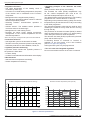
Increase in temperature of the tank (without drawing)
Domestic hot water temperature (with open tab).
°C
70
°C
60
80
70
50
10 l/min.
12,5 l/min.
15 l/min.
60
40
50
40
30
30
20
20
10
10
0
0
0
5
10
15
20
25
30
0
35
5
min.
10
15
20
25
min.
¿JXUH+RWZDWHUSHUIRUPDQFHV
- 14 -
Installation and commissioning instructions "1485 - EN"
Heat pump alféa hybrid duo gas
2 Installation
2.1
Installation and maintenance rules
The appliance must be installed and maintained by an
approved practice.
2.2
Unpacking and reserves
2.2.1 Reception
When the courier is present, carefully check the general
appearance of the appliances, check that the outdoor
unit has not been in horzontal position. In the event
of disagreement, write to the courier within 48 hours
mentioning all reserves and send a copy of this letter to
the After Sales Department.
2.2.2 Handling
The outdoor unit must not be in horizontal position during
transport. Transport in a horizontal position creates risk
RIGDPDJHWRWKHDSSOLDQFHE\PRYLQJWKHFRROLQJÀXLG
and damaging the compressor's suspension.
Damage caused by transport transport in horizontal
position is not covered by the warranty.
If required, the outdoor unit may be tilted only when
being moved by hand (to get it through a doorway, or
up stairs...). This operation must be carried out carefully
and the appliance must be immediately returned to the
vertical position.
2.2.3 Containment of refrigerant circuits
All refrigerant circuits fear contamination from dust and
moisture. If such pollutants introduced into refrigeration
circuit, they can contribute to degrade the reliability of
the heat pump.
" ,W¶V QHFHVVDU\ WR HQVXUH FRUUHFW FRQWDLQPHQW
FRQQHFWLRQV DQG UHIULJHUDQW FLUFXLWV K\GUDXOLF
XQLWRXWGRRUXQLW
" ,Q FDVH RI VXEVHTXHQW IDLOXUH DQG H[SHUWLVH WKH
¿QGLQJ RI WKH SUHVHQFH RI PRLVWXUH RU IRUHLJQ
REMHFWV LQWR WKH FRPSUHVVRU RLO ZRXOG OHDG WR
V\VWHPDWLFH[FOXVLRQRIZDUUDQW\
- &KHFNXSRQUHFHLSWWKDWWKH¿WWLQJVDQGWKHUHIULJHUDWLRQ
circuit caps mounted on hydraulic unit and outdoor unit
are properly seated and locked (impossible to loosen
bare hands). If this’s not the case, tighten them using
an against wrench.
- Check also that the refrigerant connections are sealed
(plastic caps or tubes crushed at the ends and soldered).
If the caps must be removed during installation (tubes
cut by example), put back them as soon as possible.
2.2.4 Accessories supplied
3
2
1
1
Elbow
2
Plugs (x2)
(depending on
model)
3
Flexible insulating
plate
WR¿OOWKHYDFXXPRQ
the entrance of the
interconnection cable
4
Spanner
to open valves
4
for condensate evacuation
¿JXUH$FFHVVRULHVVXSSOLHGZLWKWKHH[WHUQDOXQLW
6
5
Outdoor sensor
to detect the outdoor
temperature
¿JXUH$FFHVVRULHVSURYLGHGZLWKWKHK\GUDXOLFPRGXOH
Installation and commissioning instructions "1485 - EN"
- 15 -
Heat pump alféa hybrid duo gas
2.3
Positioning
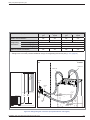
2.4
The choice of the position is particularly important
as having to move it later is a delicate operation that
UHTXLUHVDTXDOL¿HGSHUVRQ
Choose the position of the outdoor unit and the hydraulic
module after discussion with the client.
Respect the max. and min. distances between the
hydraulic module and the outdoor unit (¿JXUHSDJH),
as the performances and life of the system depend on this.
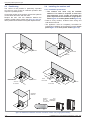
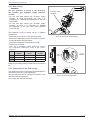
Installing the outdoor unit
2.4.1 Installation precautions
" 7KH RXWGRRU XQLW PXVW RQO\ EH LQVWDOOHG
RXWGRRUV ,I D VKHOWHU LV UHTXLUHG LW PXVW KDYH
large apertures on all 4 sides and respect the
VSDFHUHTXLUHGIRUWKHLQVWDOODWLRQVLQJOHSKDVH
model ¿JXUH or three phase model ¿JXUH)
Prefer a sunny location, sheltered from strong and
cold dominant winds.
The appliance must be completely accessible for
subsequent installation and maintenance work (single
phase ¿JXUH or three phase model ¿JXUH).
AIR
AIR
100 mm
100 mm
600 mm
AIR
AIR
100 àto300
300mm
mm
100
300 mm
250 250
mm mm
pour accès
for access
250 mm
250 mm
pour accès
for access
250250
mm mm
pour accès
for access
300 mm
minimum
600 mm
Contact
your
energy
distributor
for the installation
constraints.
AIR
¿JXUH0LQLPXPLQVWDOODWLRQFOHDUDQFHDURXQGWKHRXWGRRUXQLWVLQJOHSKDVHPRGHOV
- 16 -
Installation and commissioning instructions "1485 - EN"
Heat pump alféa hybrid duo gas
Ensure that the connections can be made easily with
the hydraulic module.
The outdoor unit can be exposed to the weather,
however avoid installing it in places where it will
become dirty or have excessive water dripping onto it
(under a leaky drainpipe for example).
Keep the outdoor unit away from sources of heat or
LQÀDPPDEOHSURGXFWV&RQWDFW\RXUHQHUJ\GLVWULEXWRU
for the installation constraints.
Ensure that the appliance does not disturb neighbours
or users (noise level, draughts caused, low of the air
blown causing a risk of freezing plants in its path).
When operating water may escape from the outdoor
unit. Do not install the appliance on a terrace; install it
at a location which is drained (bed of gravel or sand).
If installed in a region where the temperature may be
below 0°C for a long period, check that the ice does not
cause any danger. It is also possible to connect a pipe to
evacuate to the outdoor unit (¿JXUH).
7KHVXUIDFHRQZKLFKWKHRXWGRRUXQLWLV¿WWHGPXVW
- Be permeable (earth, gravel bed...),
- Support the weight comfortably,
- Permit it to be solidly attached,
- Not transmit any vibration to housing (anti-vibration
posts are available as accessories).
No obstacles must obstruct the circulation of
air through the evaporator and the fan outlet
(single phase ¿JXUH or three phase model ¿JXUH).
The wall bracket can not be used in conditions likely to
transmit vibrations, ground position is preferred.
m
0m
15
20
0m
m
m
0m
30
20
0m
m
150 mm
1000
mm
1000 mm
ou more
plus
or
1000mm
mmouorplus
more
1000
1500 mm
1000 mm
300 mm
Max. 500 mm
300 mm
25
0m
m
500 mm
25
0m
m
Max. 500 mm
1500 mm
1500
mm or
oumore
plus
1500 mm
500 mm
1500 mm
1500
mm or
oumore
plus
Contact
your
energy
distributor
for the installation
constraints.
15
00
mm
500 mm
Max. 300 mm
¿JXUHMinimum installation clearance around the outdoor unit (three phase models)
Installation and commissioning instructions "1485 - EN"
- 17 -
Heat pump alféa hybrid duo gas
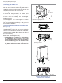
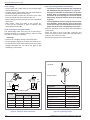
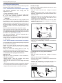
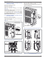
2.4.2 Fitting the outdoor unit
The outdoor unit must be raised by at least 50 mm
from the ground. In snowy regions, this height must be
increased but must not exceed 1.5 m (¿JXUH).
- Attach the outdoor unit using screw and spring or split
washers to ensure they do not come loose.
" Warning
In regions with heavy snowfall, if the outdoor unit's
HQWUDQFHDQGH[LWDUHEORFNHGE\VQRZLWPD\EHGLI¿FXOW
to heat up and may probably cause a breakdown.
Build an awning or place the appliance on a tall support
ORFDOFRQ¿JXUDWLRQ
- Put the appliance on a solid support to minimise
impact and vibration.
- Do not place the appliance directly on the ground as
this may cause problems.
B
B
H* > 50 mm
C
**InDans
regions
frequent
snowfall, enneigées,
(H) must be greater
les with
régions
fréquemment
than
the average
layer ofà snow.
(H) doit
être supérieur
la couche moyenne de neige.
Depending
on model
Suivant modèle
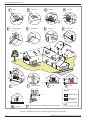
2.4.3 Connecting the condensate evacuation pipe
(see ¿JXUH).
If an evacuation pipe must be used:
- Use the elbow provided (C DQG FRQQHFW D ÀH[LEOH
hose of 16 mm diameter to evacuate the condensates.
- Use the plug(s) supplied (%WRREVWUXFWWKHRUL¿FHRI
the condensate tray.
)LW VR WKDW JUDYLW\ ÀRZ RI WKH FRQGHQVDWHV LV HQVXUHG
(waste water, rainwater, gravel bed).
" If the appliance is installed in a region where
WKH WHPSHUDWXUH PD\ IDOO EHORZ & IRU ORQJ
SHULRGV¿WWKHHYDFXDWLRQSLSHZLWKDUHVLVWDQFH
trace to avoid it icing over. The resistance trace
PXVWKHDWQRWMXVWWKHHYDFXDWLRQSLSHEXWDOVR
WKH ERWWRP RI WKH FRQGHQVDWH GULS WUD\ RI WKH
appliance.
44holes
trous
(Ø 10 mm)
C
Depending
on model
Suivant modèle
B
44holes
trous
(Ø 12 mm)
B
C
Depending on model
+PP
%
%
C
C
%
%
4 holes
(ø 12 mm)
¿JXUH)LWWLQJWKHRXWGRRUXQLW
evacuation of the condensates
- 18 -
Installation and commissioning instructions "1485 - EN"
Heat pump alféa hybrid duo gas
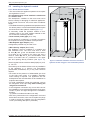
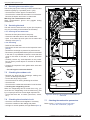
2.5
,QVWDOOLQJWKHK\GUDXOLFPRGXOH
2.5.1 Room where to install
The room where the appliance operates must respect
the regulations in force.
7KLVHTXLSPHQWPD\QRWEHLQVWDOOHGLQDEDWKURRP
or a shower room.
The atmospheric conditions in the room must not be
humid; humidity is damaging for electrical appliances.
,IWKHJURXQGLVKXPLGRUVRIWXVHDEDVHRIVXI¿FLHQW
height.
300 mm
B
To facilitate the servicing operations and permit access to
WKHYDULRXVSDUWVLWLVUHFRPPHQGHGWKDWVXI¿FLHQWVSDFH
be left all around the hydraulic module (¿JXUH).
1800 mm
If necessary, install the hydraulic module on antivibration posts or any other resilient material to limit
the sound level caused by vibration.
5RRPVHDOHGWXUERSLSH (C13, C33)
$V WKH DSSOLDQFH LV OHDNSURRI QR VSHFL¿F SUHFDXWLRQV
are required concerning ventilation of the premises.
With Separate pipe adaptor (C53)
&RQ¿JXUDWLRQSRVVLEOHRQO\LQERLOHUURRP
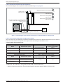
:LWKFKLPQH\DGDSWRU (B23, B23P)
The appliance must be installed in a suitable and
well ventilated room. The room must have a fresh
air inlet (A) with a free non-blockable cross section
of at least 50 cm2 located in the lower part and a
used air outlet (B) with a free non-blockable cross
section of at least 100 cm2 positioned in the upper
part and opening directly outdoors (see ¿JXUH ).
The air renewal volume must be at least (P(kW) x 2) m3/h,
i.e. 48 m3/h.
The warranty on the heater will not cover any installation
of the appliance in a chlorine rich atmosphere
(hairdressers, launderette, etc.) or any other corrosive
vapours.
A
125 mm
1000 mm
¿JXUHMinimum installation clearances around the
K\GUDXOLFPRGXOHDQGJDSVWRWKHFRPEXVWLEOHSDUWLWLRQV
%HFDUHIXORIWKHSUHVHQFH RILQÀDPPDEOH JDVFORVH
to the heat pump when it is installed, especially
when brazing is required. The appliances are not
antiexplosion and must therefore not be installed in an
explosive atmosphere.
- To avoid condensation inside the condenser, remove
the refrigerant circuit caps RQO\ ZKHQ EXLOGLQJ WKH
refrigerant connections.
- If the refrigerant connection only occurs at the end of
the installation, be sure that the refrigerant circuit caps*
remain in place and tight throughout the installation
duration.
* (hydraulic unit side and outdoor unit side)
- After every intervention on the refrigeration circuit and
EHIRUH¿QDOFRQQHFWLRQWDNHFDUHWRUHSODFHWKHSOXJV
in order to avoid any pollution from the refrigeration
circuit (The sealing with tape is prohibited).
Installation and commissioning instructions "1485 - EN"
- 19 -
Heat pump alféa hybrid duo gas
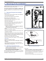
2.6
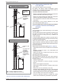
&KLPQH\HYDFXDWLRQSLSH%%3
The evacuation pipe must comply with the regulations
in force.
The evacuation pipe must be dimensioned (according
to standard NF EN 13384-1).
The pipe must only be connected to a single appliance.
The pipe must be waterproof.
The pipe must have good thermal insulation.
The evacuation pipe must comply with the decree of
22nd October 1969 (¿JXUH).
%3W\SH¿JXUHSDJH)
The smoke pipe entry must be located:
OK
Either in the premises which contain the appliance,
Or in adjacent premises.
- In this case, it must be coupled to a wall that separates
the two premises to enable direct connection through
this wall.
- 7KHFURVVSLHFHWKURXJKWKH¿UVWZDOOPXVWEHOHDNSURRI
- When the cross pieces are installed for the other walls,
no sealing system must be implemented to enable the
wall / pipe annular area to be completely free.
- The distance between the combustion product
evacuation pipe and the chimney pipe walls must be
greater than 20 mm.
- The space between the evacuation pipe and the
chimney pipe must be linked at the top with the outside
directly through an opening of at least 100 cm².
2.7
40 cm
1,2 m
< 15°
40 cm
40 cm
8m
8m
&KLPQH\FRQQHFWLRQSLSH%%3
The connection pipe must comply with the regulations
in force.
The cross section of the connection pipe must not be
smaller than the outlet nozzle of the appliance.
The connection pipe must be removable.
The evacuation nozzle is to be connected to the pipe so
that there are no leaks.
5HPLQGHU7KHFKLPQH\DGDSWRUSURYLGHGPXVWEH
XVHG(¿JXUH).
The appliance will be connected to the evacuation pipe
using commercially-available pipes that are approved to
withstand combustion products, condensate and smoke
temperatures of at least 120 °C.
7KHXVHRIDOXPLQLXPFRQQHFWLRQSLSHVLVSURKLELWHG
By design, the boiler's smoke temperature cannot
exceed 120 °C, therefore, there is no need to add an
evacuation pipe protection thermostat.
%
,WLVVWURQJO\UHFRPPHQGHGWR¿WDÀXHUHJXODWRUWRWKHSLSH
when the low pressure of the chimney is greater than 30 Pa.
%3
The drain T is not necessary since the condensate recovery
is incorporated into the boiler (¿JXUHSDJH).
- 20 -
¿JXUHAssembly of the chimney
DGDSWRU%%3
¿JXUH+HLJKWRIWKHEDVH
RIWKHHYDFXDWLRQGXFW%%3
Installation and commissioning instructions "1485 - EN"
Heat pump alféa hybrid duo gas
%W\SHFKLPQH\FRQQHFWLRQ
16 and 24
kW models
only.
Pipe dimensions
calculated
according to
standard EN
13384-1.
3%
RCh
ACh
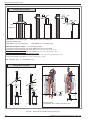
2.8
Room-sealed connection pipe
&&&
The connection pipe must be removable.
By design, the boiler's smoke temperature cannot
exceed 120 °C, therefore, there is no need to add an
evacuation pipe protection thermostat.
7KHERLOHUPXVWEHFRQQHFWHG
Either to a horizontal oxidising air intake and combustion
product evacuation mechanism (C13 type).
Either to a vertical oxidising air intake and combustion
product evacuation mechanism (C33 type).
Or to separate air intake and smoke evacuation pipes
(C53 type).
Characteristics of the suction elements to be used
(see characteristics table page 7).
7KHXVHRIDOXPLQLXPFRQQHFWLRQSLSHVLVSURKLELWHG
2.8.1 Concentric horizontal room-sealed pipe
&W\SH
Drain
T
%3W\SHFKLPQH\FRQQHFWLRQ
Flexible or rigid
pipe.
3%
Pipe dimensions
calculated
according to
standard EN
13384-1 and
max pressure
available on the
nozzle.
ACh
ACh - Chimney adaptor 80 (073 295).
RCh - Chimney adaptor 80-125 (073 423).
¿JXUHConnection possibilities (B23 and B23P type)
Installation and commissioning instructions "1485 - EN"
Regulations
The evacuation pipe must lead directly to the outside
through a wall.
The air intake and burnt gas evacuation opening must
be placed at least 0.40 m away from any opening
windows and 0.60 m away from any ventilation air
intake openings.
If the evacuation leads onto a public or private road, it
must be protected from any external interventions likely
to harm its normal operation.
When the terminal leads out over a horizontal surface
(ground, terrace), a minimum distance of 0.30 m must be
respected between the base of the terminal and this surface.
Recommendations
Respect the max authorised lengths (¿JXUHSDJH).
- Horizontal sections must be avoided on the evacuation
pipes.
- Respect a minimum slope of 3% downwards and
towards the boiler.
- Make sure that the air intake and smoke exit circuits
are perfectly sealed.
Mounting the room-sealed pipe
Plug the different elements into each other (terminal,
pipe, elbow, etc.). Coat the seal with liquid soap to make
it easier to plug in.
- Adapt the pipe length.
- Use long extensions to limit the number of junction
pieces.
- Refer to the supplier's instructions.
- Determine the boiler's position in relation to the suction
pipe output.
- Drill a hole 150 mm in diameter in the wall
- Insert the pipe assembly into the hole in the wall and
connect it to the boiler's adaptor, making sure it is sealed.
- Seal the pipe terminal into the wall using polyurethane
foam to enable it to be removed if necessary.
- Provide a telescopic element to enable the smoke
outlet to be removed during maintenance operations.
- 21 -
Heat pump alféa hybrid duo gas
&W\SHSLSHFRQQHFWLRQ
L1
L1
90°
3%
3%
3%
L2
90°
L2
3%
90°
Mini
90°
L3
1899 mm
16 et 24 kW
1577 mm
28 et 34 kW
1698 mm
͞HOERZ = 1 m of straight pipe.
Existing evacuation pipe.
͞RIIVHW = 0.5 m of straight pipe.
͞HOERZ = 0.5 m of straight pipe.
͞RIIVHW = 0.3 m of straight pipe.
0D[LPXPVWUDLJKWOLQHOHQJWK = 11 m (excluding terminal)
This length must be reduced by 1 m per 90° elbow and 0.5 m per 45° elbow.
Example of C13 type connection with 3 90° elbows: L1 + L2 + L3 + (3 x 1 m) d 11 m.
Example of C33 type connection with 2 45° elbows: L1 + L2 + L3 + (2 x 0,5 m) d 11 m .
Example of C33 type connection with Rénolux system:
͞HQWU\LQWRZDOOZLWKHOERZVDQGRIIVHWV//[P[Pd 11 m.
͞HQWU\LQWRZDOOZLWKRIIVHWV//[Pd 11 m.
RT - Telescopic pipe.
T - terminal (max 1 m).
&W\SHSLSHFRQQHFWLRQ
T
T
L1
L1
L1
L
L2
45°
RT
45°
L3
L2
90°
RT
L2
90°
Rénolux system
for adaptation to the existing evacuation pipe.
¿JXUHConnection possibilities (C13 and C33 type)
- 22 -
Installation and commissioning instructions "1485 - EN"
Heat pump alféa hybrid duo gas
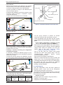
2.8.2 &RQFHQWULFYHUWLFDOSLSH&W\SH
Regulations
The roof terminal must be placed at least 0.40 m away
from any opening windows and 0.60 m away from any
ventilation air intake openings.
Recommendations
Respect the max authorised lengths (¿JXUH).
- Make sure that the air intake and smoke exit circuits
are perfectly sealed.
Mounting the suction pipe:
- Plug the different elements into each other (terminal,
pipe, elbow, etc.). Coat the seal with liquid soap to
make it easier to plug in.
- Adapt the pipe length.
- Use long extensions to limit the number of junction
pieces.
- Refer to the supplier's instructions.
- Provide a telescopic element to enable it to be removed
during maintenance operations.
5pQROX[ V\VWHP IRU DGDSWDWLRQ WR WKH H[LVWLQJ
evacuation pipe.
The Rénolux system enables connection to the boiler's
suction pipe.
7KH 5pQROX[ V\VWHP LQFOXGHV WKH WHUPLQDO WKH ÀH[LEOHKRVHWKHDGDSWDWLRQDQGVHDOLQJSDUWVDQGWKH
¿QLVKLQJSODWH
The chimney pipe's internal dimension must be at least
equal to 140 mm in diameter or side.
Check the pipe's seal and range.
" &OHDQLQJWKHHYDFXDWLRQSLSHEHIRUHLQVWDOODWLRQ
7KH FKLPQH\ PXVW EH FOHDQHG WR UHPRYH DOO
LPSHUDWLYH DQG VRRW WKDW PD\ GDPDJH WKH
appliance.
Make sure that the evacuation pipe's intake and outlet
connections are perfectly sealed.
2.8.3 Separate air intake
DQGVPRNHHYDFXDWLRQSLSHV&W\SH
&W\SHSLSHFRQQHFWLRQ
T
L1
3%
90°
L2
90°
L
ACD
0D[LPXPVWUDLJKWOLQHOHQJWK = 11 m
(excluding terminal).
This length must be reduced by 1 m per 90° elbow and 0.5
m per 45° elbow.
Connection example:
With 2 90° elbows: L1 + L2 + (2 x 1 m) d 11 m.
With 1 90° elbow: L + (1 x 1 m) d 11 m.
ACD - Separate pipe adaptor 073428.
T - terminal (max 1 m).
¿JXUHConnection possibilities (C53 type)
The air intake and combustion product evacuation
terminals must not be installed on walls opposite the
building.
The smoke pipes must be protected against all
mechanical impact.
Installation and commissioning instructions "1485 - EN"
- 23 -
Heat pump alféa hybrid duo gas
B
Leaf
C
Air inlet
D
Dormer
Dormer
0,4 m
0,4 m
0,6 m
0,4 m
0,4 m
0,6 m
0,4 m
2m
A
L<1m
0,4 m
0,4 m
0,4 m
0,4 m
0,4 m
E
F
Pinion with leaf
0,4 m
G
Blind pinion
L>1m
H
Roof rib
Anti-snow
0,4 m
L1
0,4 m
30 cm
mini
= L1
0,6 m
0,6 m
mini
H
A
2m
F
B
C
M
mini
J
I
G
D
K
0,4 m
N
E
1,8 m
mini
L
1,8 m
mini
0,4 m
0,4 m
0,4 m
L1
0,3 m
0,4 m
0,6 m
mini
= L1
0,6 m
mini
0,4 m
0,4 m
2m
0,3 m
0,3 m
I
Leaf
J
K
Incoming angle
0,6 m
0,4 m
L
Leaf
Leaf
0,6 m
/HJHQG
Prohibited areas
0,15 m
1,2 m
Areas that are not
recommended
2m
0,3 m
Authorised areas
M
Air inlet
N
Area surrounding a smoke pipe with natural draft
¿JXUH7HUPLQDOORFDWLRQUXOHVIRUOHDNSURRIJDVERLOHUV&&&
- 24 -
Installation and commissioning instructions "1485 - EN"
Heat pump alféa hybrid duo gas
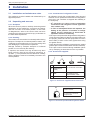
2.9
Refrigerant connections
" 7KLV DSSOLDQFH XVHV WKH UHIULJHUDWLQJ ÀXLG
R410A.
5HVSHFWWKHOHJLVODWLRQIRUKDQGOLQJUHIULJHUDWLQJÀXLGV
2.9.1 Rules and precautions
After every intervention on the refrigeration circuit and
EHIRUH¿QDOFRQQHFWLRQWDNHFDUHWRUHSODFHWKHSOXJVLQ
order to avoid any pollution from the refrigeration circuit.
0LQLPXPQHFHVVDU\WRROV
- Set of manometers (Manifold) with hoses exclusively
UHVHUYHGIRU+)&V+\GURÀXRURFDUERQV
- Vacuum gauge whith isolation valves.
- Vacuum pump specially for HFCs (use of a traditional
YDFXXP SXPS LV DXWKRUL]HG LI DQG RQO\ LI LW LV ¿WWHG
with a non-return valve on the suction side).
- Flaring tool.
- Pipe-cutter.
- Deburring tool.
- Wrenches.
- 5HIULJHUDQWJDVOHDNGHWHFWRUFHUWL¿HGVHQVLWLYLW\J\HDU
" 3URYLVLRQ RQ XVLQJ WRROV WKDW KDYH EHHQ LQ
FRQWDFWZLWK+&)&V5IRUH[DPSOHRU&)&V
" 7KH PDQXIDFWXUHU GHFOLQHV DQ\ OLDELOLW\ ZLWK
UHJDUGWRWKHJXDUDQWHHLIWKHDERYHLQVWUXFWLRQV
DUHQRWREVHUYHG
7XEHH[SDQGHUVÀDUHGFRQQHFWRUV
" /XEULFDWLRQ ZLWK PLQHUDO RLO IRU 5 5
is not allowed.
- Only lubricate with polyolester refrigerating oil (POE).
,I32(RLOLVQRWDYDLODEOH¿WZLWKRXWRLO
Thermally insulate the gas and liquid pipe to avoid
all condensation. Use insulating sleeves that resist
temperatures of over 90°C. In addition, if the level of
humidity where the refrigerating pipes risks exceeding
70%, protect them with insulating sleeves. Use a
15 mm thicker sleeve if the humidity reaches 80%, and
a 20 mm thicker sleeve if the humidity exceeds 80%.
If the recommended thicknesses are not respected
in the conditions described above, condensation will
form on the surface of the insulation. Finally, ensure
that insulating sleeves are used that have a thermal
conductivity equal to 0.045 W/mK or lower when the
temperature is equal to 20°C. The insulation must be
impermeable to resist the steam passing during the
defrosting cycles (glass wool is prohibited).
2.9.2 Refrigerating connections
The outdoor unit must be connected to the hydraulic
unit RQO\ with new copper pipes and connections
(refrigeration quality), insulated separately.
Respect the diameters of pipe and the authorised
lengths (¿JXUH).
If the refrigeration connections are exposed to
weathering or UV- and the insulation is not strong, it is
necessary to provide protection.
The minimum length of the cooling links if 5 m for
correct operation.
The appliance's warranty will be void if it is applied with
cooling links that are shorter than 5 m.
Handle the pipes and pass them through the walls
withthe protection plugs in place.
&RDWWKHÀDUHGVXUIDFHZLWK
refrigerating oil POE.
Do not use mineral oil.
%UD]LQJRQWKHUHIULJHUDWLQJFLUFXLWLIUHTXLUHG
- Silver brazing (40% minimum recommended).
- Brazing with a dry Nitrogen stream only.
To eliminate the swarf from the pipes, use dryNitrogen to
avoid introducing humidity that can harm the operation
of the appliance. In general, take all precautions to
avoid humidity penetrating into the appliance.
Installation and commissioning instructions "1485 - EN"
- 25 -
Heat pump alféa hybrid duo gas
2.9.5 &RQQHFWLQJWKHÀDUHFRQQHFWLRQV
2.9.3 Flaring
- Cut the tube with a tube cutter to the required length
without deforming it.
- Carefully deburr while holding the tube downwards to
avoid introducing swarf into the tube.
- 5HPRYHWKHÀDUHQXWIURPWKHFRQQHFWRURQWKHYDOYH
WREHFRQQHFWHGDQG¿WWKHWXEHLQWRWKHQXW
- Flare it leaving the tube protruding fro the expandable
ÀDULQJWRRO
- $IWHU ÀDULQJ FKHFN WKH VWDWH RI WKH MRXUQDO L).
It must not be scratched or signs of splitting. Also
check the dimension (%).
2.9.4 )RUPLQJWKHUHIULJHUDQWWXEHV
The refrigerating tubes must only be formed using a
bending machine or a bending spring in order to avoid
any risks of crushing or splitting.
" Warning!
" &RQQHFWLRQVPXVWEHPDGHWKHGD\RIWKH¿OOLQJ
WKHLQVWDOODWLRQZLWKJDVVHHSDUDSDJH).
" 3D\VSHFLDODWWHQWLRQWRWKHSRVLWLRQRIWKHWXEH
aligned with its connector to avoid damaging
WKHWKUHDG$FRUUHFWO\DOLJQHGFRQQHFWRUFDQEH
¿WWHGHDVLO\E\KDQGZLWKRXWPXFKIRUFHEHLQJ
required.
" 7KHUHIULJHUDWLQJFLUFXLWLVYHU\VHQVLWLYHWRGXVW
DQG KXPLGLW\ FKHFN WKDW WKH ]RQH DURXQG WKH
FRQQHFWLRQLVGU\DQGFOHDQEHIRUHUHPRYLQJWKH
plugs that protect the refrigerating connectors.
- Remove the plugs from the pipes and refrigerating
connections
- 3ODFH WKH WXEH LQ IURQW RI WKH ÀDUH FRQQHFWRU DQG
screw on the nut by hand, holding the connector with a
spanner, until contact is made.
- 5HVSHFWWKHWLJKWHQLQJWRUTXHVGH¿QHG
Remove the insulation locally to bend the tubes.
Do not bend the copper to an angle of more than 90°.
Do not bend the tubes more than 3 times at the same
position otherwise this can cause the pipe to split
(hardening of the metal).
Spanner
Torque wrench
%
Nut
Flare
L
Expander
'HVLJQDWLRQ
tube pipe
C
Dimensions in mm
ø pipe
L
%0
C
6.35 (1/4")
1.8 to 2
9.1
17
9.52 (3/8")
2.5 to 2.7
13.2
12.7 (1/2")
2.6 to 2.9
15.88 (5/8")
2.9 to 3.1
Flare nut 6.35 mm (1/4")
14 to 18 Nm.
Flare nut 9.52 mm (3/8")
33 to 42 Nm.
Flare nut 12.7 mm (1/2")
50 to 62 Nm.
Flare nut 15.88 mm (5/8")
63 to 77 Nm.
Plug (A) 3/8", 1/4"
20 to 25 Nm.
Plug (A) 1/2"
25 to 30 Nm.
22
Plug (A) 5/8"
30 to 35 Nm.
16.6
26
Plug (B) 3/8", 5/8"
10 to 12 Nm.
19.7
29
Plug (B) 1/2", 1/4"
12.5 to 16 Nm.
¿JXUH)ODULQJIRUÀDUHGFRQQHFWLRQV
- 26 -
7LJKWHQLQJWRUTXH
¿JXUH7LJKWHQLQJWRUTXHV
Installation and commissioning instructions "1485 - EN"
Heat pump alféa hybrid duo gas
Heat pump model
DOIpDK\EULGJDVVLQJOHSKDVH
OLTXLG
JDV
OLTXLG
5/8"
3/8"
5/8"
3/8"
(D1) 5/8"
(D2) 3/8"
(D1) 5/8"
(D2) 3/8"
Outdoor unit connectors
Diameter
5HIULJHUDWLQJ
connections
DOIpDK\EULGJDVWKUHHSKDVH
JDV
0LQLPXPOHQJWK/
5
5
0D[LPXPOHQJWK/
20 *
15 * / 20 **
'LIIHUHQFHLQKHLJKW'
20 *
15 * / 20 **
Hydraulic module connectors
5/8"
3/8"
5/8"
3/8"
*: without additional charge of R410A
** : 7DNLQJLQWRDFFRXQWWKHSRWHQWLDODGGLWLRQDOFKDUJHRIUHIULJHUDWLQJÀXLG R410A (see § 2.10.3, page 30)
Outdoor
unit
Hydraulic
module
Flare nut
Flare nut
Heat pump
Hydraulic
module
"Liquid"
valve
Flare
nut
Heat pump
L D
"Liquid" refrigerating connection
diameter D2
"Gas"
valve
Flare
nut
Outdoor unit
"Gas" refrigerating connection
diameter D1
¿JXUH5HIULJHUDWLQJOLQNFRQQHFWLRQDFFHSWHGGLDPHWHUVDQGOHQJWKV
Installation and commissioning instructions "1485 - EN"
- 27 -
Heat pump alféa hybrid duo gas
2.10 Filling the installation with gas
" This operation is reserved for installers familiar
with the legislation for handling refrigerants.
" Creating a vacuum with a vacuum pump is
HVVHQWLDOVHH$11(;
" 1HYHUXVHHTXLSPHQWXVHGEHIRUHKDQGZLWKDQ\
refrigerant other than a HFC.
" 5HPRYH WKH UHIULJHUDQW FLUFXLW FDSV RQO\ ZKHQ
EXLOGLQJWKHUHIULJHUDQWFRQQHFWLRQV
" 8QIDYRUDEOHVFRQGLWLRQV
,IWKHRXWGRRUWHPSHUDWXUHLVEHWZHHQDQG
&it’s obliged to have a vacuum gauge for
validate the pump down operation and use method
3 empty (see ANNEX 2).
,IWKHRXWGRRUWHPSHUDWXUHLVEHORZ&,
LW¶VVWURQJO\QRWUHFRPPHQGHGWRGRWKH¿OOLQJWKH
installation with gas.
$11(;
0HWKRGHPSW\
- Connect the high pressure hose to the Manifold,
("Gas" connection). A valve must be mounted on
WKH ÀH[LEOH KRVH IURP WKH YDFXXP SXPS LQ RUGHU
to isolate it.
a) Pump down to the desired value (see table ANNEX 1),
kit
JeuManometer
de manomètres
(Manifold)
(manifold)
Low
Basse Lo
pressure
pression
Hi
High
Haute
pressure
pression
Vacuum gauge
Vacuomètre
Liaison...
UE Connection
Liquid
liquide
Gas
gaz
MH
Vacuum
Pompe àpump
vide
E) Stop the vacuum pump, close the valve end of
the service hose (yellow). Connect the hose to the
expansion valve of the nitrogen bottle, inject 2 bars,
FORVHWKHÀH[LEOHKRVHYDOYH
Lo
$11(;
0HWKRG IRU FDOLEUDWLRQ DQG FRQWURO RI D YDFXXP
pump
Vacuum
- Check the oil level of the
gauge
Vacuomètre
vacuum pump.
Clogged
Flexible
ÀH[LEOH
bouché
Vacuum
- Connect the vacuum pump hose
Pompe
pump
à vide
with the vacuum gauge
according to the scheme.
- Pump down during 3 minutes.
- After 3 minutes, the pump reaches its threshold
value and the vacuum gauge needle does not move.
- Compare the obtained pressure with the value of the
table. Depending on the temperature, this pressure
must be less than the value indicated in the table.
!,ILW¶VQRWWKHFDVHUHSODFHWKHJDVNHWÀH[LEOH
hose or the pump.
7&
&7&
&7&
&7
3PD[
EDU . .
PEDU
. . . 0.009 . . .
.....9.....
. . . 0.015 . . .
. . . . 15 . . . .
. . . 0.020. . .
. . . .20 . . . .
Hi
Nitrogen
Azote
High
Haute
pressure
pression
Connection
UE Liaison...
Liquid
liquide
Gas
gaz
MH
c) 5HFRQQHFWWKHÀH[LEOHKRVHWRWKHYDFXXPSXPS
turn on and gradually open the hose valve.
Lo
Hi
High
Haute
pressure
pression
Connection
UE Liaison...
Liquid
liquide
Gas
gaz
MH
d) Repeat this at least three times.
" Reminder,W¶VVWULFWO\IRUELGGHQWRSHUIRUP
these operations with refrigerant.
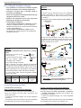
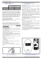
2.10.1 Commissioning procedure
&KHFNEHIRUHFRQQHFWLQJ
*DVFRQQHFWLRQFRQWUROODUJHGLDPHWHU.
- Connect the "Gas" connection to the outdoor unit.
- Blow dry nitrogen into the "Gas" connection and
observe this end:
x If water or impurities emerge, use a new refrigerant
connection.
x2WKHUZLVHSHUIRUPWKHÀDUHDQGFRQQHFWLPPHGLDWHO\
the refrigerant connection to the hydraulic unit.
- 28 -
/LTXLGFRQQHFWLRQFRQWUROVPDOOGLDPHWHU.
- Connect the "Liquid" connection to the outdoor unit.
- Blow dry nitrogen into "Gas" connection – condensor
- "Liquid" connection assembly and Observe this
end (Outdoor unit side).
x If water or impurities emerge, use a new refrigerant
connection.
x2WKHUZLVHSHUIRUPWKHÀDUHDQGFRQQHFWLPPHGLDWHO\
the refrigerant connection to the outdoor unit.
Installation and commissioning instructions "1485 - EN"
Heat pump alféa hybrid duo gas
First seal test
- Remove the protective plugs (%) from the charging
hole (Schrader) in the "Gas" valve (large diameter).
- Connect the high pressure hose to the Manifold.
- Connect the bottle of nitrogen to the Manifold (Use
only dry nitrogen type U)
- Pressurize the refrigerant circuit with nitrogen (10 bar
maximum) ("Gas" connection – condensor - "Liquid"
connection assembly).
- Let the circuit under pressure for 30 minutes.
Refrigeration
connexion
Refrigeration
connecxion
(Gas)
Plug (A)
3-way valve
Hex / Allen key of 4 mm
Load orifice
Lo
Hi
Nitrogen
Azote
Max.max.
10 bar
10 bars
during 30 mn mini.
30 mn mini
High
Haute
pressure
pression
Liaison...
UE Connection
Liquid
liquide
Gas
gaz
Service hose (blue)
Plug (B)
High
hosepush-button
(red)
fittedpressure
with valve
¿JXUHConnexion of the hose on the "Gaz" valve
MH
- Search for leaks with a leak detector product, repair
and repeat the test.
Lo
High
Haute
pressure
Hi
Closed valve,
Vanne
fermée,
pressure control
Contrôle pression
pression
Leak control
Contrôle
d’étanchéité
UE Liaison...
liquide
gaz
MH
- When the pressure is stable and leakage is excluded,
drain nitrogen letting a pressure above atmospheric
pressure (0,2 to 0,4 bar).
&UHDWLQJ D YDFXXP DQG ¿OOLQJ WKH UHIULJHUDWLRQ
connections with gas
- If necessary, calibrate the Manifold gauge to 0 bar.
Adjust the vacuum gauge to the atmospheric pressure
(around 1013 mbar)
- Connect the vacuum pump to the Manifold. Connect
a vacuum gauge if the vacuum pump is not equipped.
Lo
Hi
High
Haute
pressure
pression
Vacuum gauge
Vacuomètre
Connection
UE Liaison...
Liquid
liquide
Gas
gaz
- Let the pump continue to operate for another
30 minutes minimum after reaching the vacuum.
- Close the Manifold valve and then stop the vacuum
pump ZLWKRXW GLVFRQQHFWLQJ DQ\ RI WKH KRVHV LQ
place.
" ,I WKH RXWGRRU WHPSHUDWXUH LV EHWZHHQ DQG
&XVHPHWKRGHPSW\VHH$11(;
- Remove the access plugs (A) from the valve controls.
- If an additional charge is requires, add the additional
FKDUJH EHIRUH ¿OOLQJ WKH K\GUDXOLF XQLW ZLWK JDV
Please refer to the para. "Additional charge
(outdoor three phase unit)", page 30.
- First of all fully open the "Liquid" valve (small)
and then the "Gaz" valve (large) using a hex key
(counterclockwise
direction)
without
forcing
excessively against the stop.
- Remove the hose rapidly to the Manifold.
- 5H¿WWKHRULJLQDOFDSVEHVXUHWKH\DUHFOHDQDQG
tighten them to the recommended tightening torque.
The sealing is performed in the caps only metal to metal.
The outdoor unit does not contain any additional
refrigerant, enabling the installation to be purged.
Flushing is strictly forbidden.
2.10.2 Sealing test
MH
Vacuum
Pompepump
à vide
- Create a vacuum until the residual pressure* in the
circuit falls below the value given in the following table.
(* measured with the vacuum gauge)
7&
&7&
&7&
&7
3PD[
EDU . .
PEDU
. . . 0.009 . . .
.....9.....
. . . 0.015 . . .
. . . . 15 . . . .
. . . 0.020 . . .
. . . .20 . . . . .
Installation and commissioning instructions "1485 - EN"
Once the refrigeration circuit has been gassed as
described above, check that all the refrigeration
connectors are gas-tigh (4 connectors).
The sealing test must be performed with an approved
JDVGHWHFWRU,IWKHÀDULQJVKDYHEHHQPDGHFRUUHFWO\
there should be no leaks.
" If there is a leak:
- Bring the gas into the outdoor unit (pump down).
- Make the connection again.
- Repeat the commissioning procedure.
- 29 -
Heat pump alféa hybrid duo gas
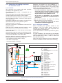
2.10.4 &ROOHFWWKHUHIULJHUDQWÀXLGLQ
the outdoor unit
2.10.3 Additional charge
RXWGRRUWKUHHSKDVHXQLW
JRI5$
per extra metre
Link length
15 m
20 m max.
Additional charge
None
250 g
The outdoor unit charge corresponds to the maximum
distances between the external unit and the hydraulic
PRGXOH GH¿QH LQ ¿JXUH SDJH . If the distances
are longer, you must make an additional charge of
R410A. The additional charge depends, for each type
of appliance, on the distance between the outdoor unit
and the hydraulic module. The additional charge of
5$PXVWRQO\EHDGGHGE\DTXDOL¿HGVSHFLDOLVW
$GGLWLRQDOFKDUJHH[DPSOH
An outdoor unit at a distance of 17 m from the hydraulic
requires an additional charge of:
Additional charge = (17 – 15) x 50 = 100 g
The charge must be added after evacuation and before
adding the gas to the hydraulic module, as follows:
- 'LVFRQQHFW WKH YDFXXP SXPS \HOORZ ÀH[LEOH KRVH
and in place connect a bottle of 410A in the liquid
drawing position.
- Open the tap of the bottle.
- 'UDLQ WKH \HOORZ ÀH[LEOH KRVH E\ ORRVHQLQJ LW VOLJKWO\
on the manifold side.
- Place the bottle on precision scales with a minimum of
10g. Note the weight.
- Carefully open the blue tap slightly and monitor the
value displayed on the scales.
- As soon as the value displayed has dropped by the
value of the calculated additional charge, close the
bottle and disconnect it.
- 6KDUSO\ GLVFRQQHFW WKH ÀH[LEOH KRVH IURP WKH
appliance.
- Add the gas to the hydraulic module.
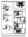
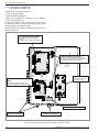
Carry out the following procedures to collect the
UHIULJHUDWLQJÀXLG
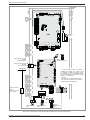
- 1- Place the Start/Stop switch in the 0 position
(item 2, ¿JXUHSDJH).
- 2- Remove the front panel of the hydraulic
module.
Open
the
electrical
cabinet.
Move the DIP SW1 of the interface board to 1.
- 3- Place the Start/Stop switch in the 1 position
WKHJUHHQDQGUHG/('VVWDUWWRÀDVKVRQVRII
- 4-The outdoor unit starts in the cold mode for
approximately 3 minutes after it is switched on.
Close the liquid valve on the outdoor unit 1 minute
after the outdoor unit is started.
- 5- Close the gas valve on the outdoor unit 1 to 2
minutes after closing the liquid valve, while the outdoor
unit continues to turn.
- 6- Disconnect the electrical power supply.
Remarks:
- Check that the Start/Stop switch is in the 0 position
before touching the DIP SW1.
- When the heat pump is operating, the collection
operation may not be activated, even if the DIP SW 1
switch is moved to ON.
- Do not forget to return the DIP SW 1 switch to OFF at
the end of the collection operation.
- If the collection operation fails, try the procedure again
by turning off the machine and opening the "gas"
and "liquid" valves. After 2 to 3 minutes repeat the
collection operation.
" Warning!
Only use R410A!
Only use tools that are adapted to the R410A (set of
pressure gauges).
Always add charge in liquid phase.
Do not exceed the maximum length or difference in
height.
DIP SW
Gas
R410A
LED1 LED2
(red)
(green)
Interface
board
Liquid
¿JXUH*DVERWWOH5$
- 30 -
¿JXUH3RVLWLRQRIWKH',3VZLWFKHVDQGWKH/('VRQ
hydraulic module interface board
Installation and commissioning instructions "1485 - EN"
Heat pump alféa hybrid duo gas
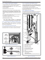
2.11 Connecting the heating circuit and
the domestic circuit
2.11.1 General
The connection must comply with trade practices
according to the regulations in force.
The heating circulation pump is integrated into the
hydraulic module.
Connect the pipe of the central heating to the hydraulic
module respecting the direction of the circulation.
The diameter of the pipe, between the hydraulic module
and the heating manifold, must be at least equal to
1 inch (26x34 mm).
Calculate the diameter of the pipes in function of the
ÀRZUDWHVDQGOHQJWKVRIWKHK\GUDXOLFV\VWHPV
Tightening torque: 15 to 35 Nm.
Use union connectors to facilitate the removal of the
hydraulic module.
3UHIHU WKH XVH RI ÀH[LEOH FRQQHFWRU KRVHV WR DYRLG
transmitting noise and vibrations to the building.
Connect the evacuations of the drain tap and the safety
valve to the drain.
Check that the expansion system is operating correctly.
&KHFN WKH H[SDQVLRQ FLUFXLW SUHVVXUH SUHLQÀDWLRQ RI
1 bar) and the calibration of the safety valve.
Reminder: Make the assembly impervious respecting
trade practices in force for the plumbing work:
- 8VHVXLWDEOHVHDOV¿EUHVHDOV2ULQJV
- 8VH7HÀRQRUKHPSWDSH
- Use sealant (synthetic as required).
Pg
Cd
EG
" ,QFHUWDLQLQVWDOODWLRQVWKHSUHVHQFHRIGLIIHUHQW
PHWDOVPD\FDXVHFRUURVLRQSUREOHPVLQZKLFK
case the formation of metal particles and sludge
PD\EHREVHUYHGLQWKHK\GUDXOLFFLUFXLW
" ,Q WKLV FDVH LW LV SUHIHUDEOH WR XVH D FRUURVLRQ
LQKLELWRU LQ WKH SURSRUWLRQV UHFRPPHQGHG E\ LWV
manufacturer.
- Refer to the "Domestic hot water and heating
treatment" section in our price catalogue.
" ,W LV DOVR QHFHVVDU\ WR HQVXUH WKDW WKH ZDWHU
WUHDWHGGRHVQRWEHFRPHDJJUHVVLYH
2.11.2 Rinsing the installation
Before connecting the hydraulic module to the
installation, rinse the heating system correctly to
eliminate the particles that could compromise the
correct operation of the appliance.
Do not use solvents or aromatic hydrocarbons (petrol,
diesel, etc.).
)RU ROGHU LQVWDOODWLRQV ¿W D GHFDQWLQJ SRW RI DGHTXDWH
capacity on the boiler return circuit and at the lowest
point equipped with a drain, in order to collect and
evacuate the impurities.
Add to the water an alkaline product and a dispersant.
5LQVHWKHLQVWDOODWLRQVHYHUDOWLPHVEHIRUH¿QDO¿OOLQJ
" GLUHFWXQGHUÀRRUKHDWLQJFRQQHFWLRQSURKLELWHG
SSu
SDEG
Reminder: The presence on the installation, of a
disconnection function of the CB type, designed to
avoid returns of heating water to the drinking water
system, is required by articles 16.7 and 16.8 of the
Typical Departmental Domestic Rules.
UE
Pg
SREG
CPr
CAR
SA2
CEG
SR
R2
SD
C
VD
D
VE
MT
CAR
BS
GS
SSa
RI
/HJHQG
%6 Hot water tank
C
Circulator
(direct heating "heating circuit " and DHW)
CAR $QWLUHWXUQÀDS
Cd
Condenser
C(* Gas exchanger circulator
CPr Pressure sensor
D
Disconnector
EG Gas exchanger
GS Safety device
MH Hydraulic module
MT Thermostatic mixer
Pg
Drain
R2
Direct heating circuit "CC2"
(1 radiator circuit)
SA2 Direct heating
ambience sensor "CC2" (option)
SD Output sensor
SD(* Gas exchanger output sensor
SE
Outdoor sensor
SR Return sensor
SR(* Gas exchanger return sensor
SSa Hot water sensor
SSu Safety valve
UE Outdoor unit
VD Directional valve
VE
Expansion tank
¿JXUH2YHUDOOYLHZRIWKHHOHFWULFDOFRQQHFWLRQV
Installation and commissioning instructions "1485 - EN"
- 31 -
Heat pump alféa hybrid duo gas
2.11.3 Filling and draining the installation
2.11.6 Connection to the domestic circuit
- Check the attachment of the pipes, that the connectors
are tight and that the hydraulic module is stable.
- Check the direction of circulation of the water and that
all of the valves are open.
- Fill the installation.
- Deactivate the non-return valves.
- Position the directional valve in intermediate position.
- :KHQ¿OOLQJGRQRWRSHUDWHWKHFLUFXODWLRQSXPSRSHQ
all of the drains of the installation and the drains of the
hydraulic module (P and A) to evacuate the air in the
pipes.
- Close the drains and add water until the pressure of
the hydraulic circuit reaches 1 bar.
- Check that the hydraulic circuit is drained correctly.
- Close the non-return valves.
- Check that there are no leaks.
- Place a safety group with a valve calibrated to 7 bar on
the cold water inlet, and connect an evacuation pipe
leading to the drain. Run the safety group according to
the manufacturer's recommendations.
- Connect the safety valve evacuation to the drain.
,WLVUHFRPPHQGHGWKDWWKHKRWZDWHURXWOHWLV¿WWHGZLWK
a thermostatic mixing valve.
" 7KH H[DFW ¿OOLQJ SUHVVXUH LV GHWHUPLQHG
according to the installation's manometric head.
2.12 Condensate evacuation
A condensate recovery system is integrated into the appliance.
It must be connected to the drain via a siphon. (¿JXUH).
1
2
3
2.11.4 &RQQHFWLRQWRDQXQGHUÀRRUKHDWLQJFLUFXLW
$Q XQGHUÀRRU KHDWLQJ FLUFXLW FDQQRW EH FRQQHFWHG
directly to the hybrid duo gas heat pump. The 2-circuit
kit must be used (optional).
5
2.11.5 Connection to a fan coil circuit
For all heat pumps of more than 11 kW, a buffer tank has
WREH¿WWHGWRWKLVFLUFXLWPLQLPXPFDSDFLW\OLWUHV
4
6
7
3
Manual
drain tap
8
9
$
Automatic
drain tap
10
3
Manual
drain tap
11
¿JXUHHydraulic module drain taps
Flap closed
(Normal operating
position)
Flap disengaged
(Filling or drain
position)
¿JXUHNon-return valve
- 32 -
1.
2.
3.
4.
5.
6.
7.
8.
9.
10.
11.
"Liquid" refrigerating connection.
"Gas" refrigerating connection.
Heating return (1 circuit).
Heating outlet (1 circuit).
Stop valve (not provided).
DHW outlet (domestic hot water).
DCW inlet (domestic cold water).
Disconnector (not provided).
Filling.
Safety device (not provided).
Connections to drain with siphon.
- Drain evacuation.
- 6afety valve evacuation.
- Condensate evacuation (acid condensate resistant pipe).
¿JXUHConnections
Installation and commissioning instructions "1485 - EN"
Heat pump alféa hybrid duo gas
2.13 Gas change
" WARNING
7KH JDV JHQHUDWRU LV SUHVHW LQ WKH IDFWRU\ WR
* SURSDQH JDV GRPHVWLF VXSSO\ SUHVVXUH
PEDU
Gas valve outlet
connector
For use with G25 natural gas, domestic supply
pressure: 25 mbar (Groninguen gas type), it is
compulsory to remove the diaphragm on the gas
valve outlet.
For use with G20 natural gas, domestic supply
pressure: 20 mbar, it is compulsory to replace
the diaphragm on the gas valve outlet (optional
conversion kit).
7KLV RSHUDWLRQ PXVW EH FDUULHG RXW E\ D TXDOL¿HG
professional.
- Dismantle the connector on the gas valve outlet.
- Remove the diaphragm in place and replace it with the
model indicated in the table below.
- Position the diaphragm in the gasket's throat.
- Restore the connector.
- Carry out a combustion check (see para. "Setting
the combustion parameters during a gas check",
page 44).
Gas
Diaphragm
marker
CO2
at min
CO2
DWPD[
G 20
20
8 to 9 %
8.5 to 9.5 %
G 25
no diaphragm
8 to 9 %
8.5 to 9.5 %
G 31
conical
9.5 to 10.5 %
10 to 11 %
¿JXUH$FFHVVWRWKHGLDSKUDJP
G31
Paste the gas setting label provided with the conversion
kit.
2.14 &RQQHFWLRQRIWKHIXHOVXSSO\
The appliance must be connected to the gas distribution
network according to current regulations:
The pipe diameter will be calculated according to the
network's rates and pressure.
Place a gas stop tap near the boiler.
Installation and commissioning instructions "1485 - EN"
¿JXUH*DVYDOYHGLDSKUDJP
- 33 -
Heat pump alféa hybrid duo gas
2.15 Electrical connections
Before carrying out any work, ensure that the general
electrical power supply is switched off.
2.15.1 &KDUDFWHULVWLFVRIWKHHOHFWULFDOSRZHUVXSSO\
The electrical installation must comply with the
regulations in force:
- France: standard NF C 15-100.
The electrical connections will only be made when
all of the other assembly operations (attachment,
assembly,...) have been carried out.
" Warning!
The contract taken out with the energy supplier must
EH VXI¿FLHQW WR FRYHU WKH SRZHU RI WKH KHDW SXPS DV
well as the sum of the power requirements of all of the
appliances likely to be operated at the same time. If
WKHSRZHUVXSSO\LVLQVXI¿FLHQWFKHFNZLWK\RXUHQHUJ\
VXSSOLHUWKHYDOXHRIWKHSRZHUVXSSO\GH¿QHGLQ\RXU
contract.
Never use electrical sockets for the power supply.
The heat pump must be powered by special lines that
are protected from the electrical housing by bipolar
circuit breakers dedicated to the heat pump, curve D for
the outdoor unit, (see tables page 35).
The electrical installation must be equipped with a
differential protection of 30 mA.
This appliance is provided to operate under a nominal
voltage of 230 V (single phase) or 400 V (three phase),
+/- 10%, 50 Hz.
2.15.2 General remarks on the electrical connections
It is essential that the phase-neutral polarity is respected
for the electrical connection.
Tighten the screws of the terminal blocks correctly.
)DLOXUH WR WLJKWHQ VXI¿FLHQWO\ PD\ FDXVH RYHUKHDWLQJ
IDXOWVRUHYHQ¿UHV
&ODPS WKH FDEOHV ZLWK VWXI¿QJ JODQGV WR DYRLG DQ\
accidental disconnection of the conductive wires.
The earth connection and its continuity must be ensured.
&RQQHFWLRQWRWKHVSULQJWHUPLQDOEORFNV
5LJLGZLUH (A)
5LJLG ZLUH LV DOZD\V SUHIHUDEOH IRU ¿[HG LQVWDOODWLRQV
especially in buildings.
- Always choose a wire that complies with current
standards (NF C 15-100 in particular).
- Bare the end of the wire over a length of around
25 mm.
- With round nosed pliers, make a loop with a diameter
that corresponds to the terminal's tightening screws.
- 7LJKWHQWKHWHUPLQDOVFUHZRQWKHORRSYHU\¿UPO\
)OH[LEOHZLUH (B)
+51) RU KLJKHU TXDOLW\ ÀH[LEOH ZLUH FDQ EH XVHG
with a few precautions:
- Strip the end of the wire over a length of around
10 mm.
- Using crimping pliers, place a round crimp lug with a
diameter corresponding to the terminal screws at the
end of the wire.
- 7LJKWHQ WKH FULPS OXJ RQ WKH WHUPLQDO ¿UPO\ ZLWK D
VFUHZGULYHU 7KH XVH RI ÀH[LEOH ZLUHV ZLWKRXW URXQG
crimp lugs is not recommended.
- Always protect the cables when run into the cable
clamps with a PVC protective sheath of a thickness
between 0.5 and 1 mm.
%: Flexible wire
A: Rigid wire
Round
crimp lug
Loop
25 mm
10 mm
Screw and special
washer
Terminal block
&RQQHFWLRQWRWKHUHJXODWLRQERDUGV
- Remove the corresponding connector and make the
connection.
Precabled wiring connector and/or screw connector
&RQQHFWLRQWRWKHVSULQJWHUPLQDOEORFNV
5LJLGZLUH
- Strip the end of the wire over a length of around
10 mm.
- 6OLGHWKHZLUHLQWRWKHRUL¿FHSURYLGHG
- Push the spring with a screwdriver so that the wire
enters the cage.
- Remove the screwdriver and check that the wire
remains blocked in the cage, and pull it to check.
)OH[LEOHZLUH
- Use bits and proceed in the same way as before.
3
2
- 34 -
1
Installation and commissioning instructions "1485 - EN"
Heat pump alféa hybrid duo gas
2.15.3 Overall view of the electrical connections
The electrical diagram of the hydraulic module is detailed in ¿JXUHSDJH.
Radio central ambient unit T78 (option)
Outdoor sensor:
cable 2x0.5 mm²
or
Central ambient unit T75 (optional):
cable 3x0.5 mm²
or
Ambient sensor T55 (optional):
cable 2x0.5 mm²
Ambient sensor T55 (optional):
cable 3x0.5 mm²
Connection of outdoor unit, hydraulic module:
(phase, neutral, earth, communication bus)
cable 4x1.5 mm²
or
Electrical
panel
Electrical power supply (phase, neutral, earth)
(see table below)
¿JXUH*HQHUDOGLDJUDPRIWKHHOHFWULFDOFRQQHFWLRQVIRUDVLPSOHLQVWDOODWLRQKHDWLQJFLUFXLW
2.15.4 &URVVVHFWLRQRIWKHFDEOHDQGSURWHFWLRQUDWLQJ
The cross sections of the cables are provided for information only and do not dispense the electrician from checking
that these cross sections correspond to the requirements and satisfy the standards in force.
3RZHUVXSSO\RIWKHRXWGRRUXQLW
6LQJOHSKDVHKHDWSXPS
9+]HOHFWULFSRZHUVXSSO\
Model
$EVRUEHGPD[SRZHU
Connection cable
OLYHQHXWUDOHDUWK
D curve circuit breaker
calibre
hybrid duo 10
3910 W
3 x 2.5 mm²
20 A
hybrid duo 13
4600 W
3 x 4 mm²
25 A
hybrid duo 16
5980 W
3 x 6 mm²
32 A
Three phase heat pump
Model
$EVRUEHGPD[SRZHU
hybrid duo 11
5865 W
hybrid duo 14
6555 W
hybrid duo 16
7245 W
9+]HOHFWULFSRZHUVXSSO\
Connection cable
OLYHQHXWUDOHDUWK
D curve circuit breaker
calibre
5 x 2.5 mm²
20 A
,QWHUFRQQHFWLRQEHWZHHQWKHRXWGRRUXQLWDQGWKHK\GUDXOLFPRGXOHThe hydraulic module is powered by the
outdoor unit, via a cable 4x1.5 mm² (phase, neutral, earth, communication bus).
" %HIRUHFDUU\LQJRXWDQ\ZRUNHQVXUHWKDWWKHJHQHUDOHOHFWULFDOSRZHUVXSSO\LVVZLWFKHGRII
Installation and commissioning instructions "1485 - EN"
- 35 -
Heat pump alféa hybrid duo gas
Terminal
Bornier
block
Interconnexion
Interconnection
between
outdoor
unit and
hydraulic
entre unité
extérieure
module
et module hydraulique
Remove the front
Déposer
la façade
panel
(2 screws)
Câble d’alimentation
générale
General power supply cable
¿JXUHAccess to the terminal block of the outdoor unit
(2 vis)
1
Fixing
Plaqueplate
de fixation
Insulation
Isolant (joint)
(gasket)
2
Cable
Serre-câble
clamp
Remove the front
panel
(2 screws)
Déposer
la façade
(2 vis)
3
Cables Câbles
(power
supply and
(alimentation
et
interconnection)
interconnexion)
Fixing plate
Plaque de fixation
4
Remove the
Déposer
(1 screw)
cover
Câbles
Cables
Clearance
Dégagement
le capot (1 vis)
“Gas”
Vanne valve
“gaz”
¿JXUHAccess to the terminal block of the outdoor unit
- 36 -
¿JXUH)LQDOLVLQJRIWKHFRQQHFWLRQRIWKHRXWGRRUXQLW
Installation and commissioning instructions "1485 - EN"
Heat pump alféa hybrid duo gas
2.15.5 Electrical connections on outdoor unit side
VLQJOHSKDVHPRGHO
Access to the connector terminals
- Remove the front panel.
- Remove the cover (¿JXUH).
- Make the connections according to the diagram
(¿JXUH).
- Use the cable clamps to avoid any accidental disconnection of the conductive wires.
- Use the attachment plate to hold the cables against
the insulating plate. (item 1 to 3 ¿JXUH ). Attach
WKHFDEOHVVRWKDWWKH\DUHQRWLQFRQWDFWZLWKWKH
pipes and the valves (item 4).
- Use the cable clamps to avoid any accidental
disconnection of the conductive wires.
- Obstruct the space at the cable inlet in the outdoor unit
with the insulating plate.
Cable
clamp
2.15.6 Electrical connections on outdoor unit side
WKUHHSKDVHPRGHO
Access to the connector terminals
- Remove the front panel. Remove the screws and the
cover of the front panel.
- Make the connections according to the diagram
(¿JXUH).
Remove the screws
and push downwards
Cables
(power supply and
inter-connection)
Terminal
block
¿JXUH)LQDOLVLQJRIWKHFRQQHFWLRQRIWKHRXWGRRUXQLW
Remove the front
panel.
¿JXUHAccess to the terminal block of the outdoor unit
side
rear
Terminal
block
1 2 3 L1 L2 L3 N
INDOOR UNIT
Inter-connection
between outdoor unit
and hydraulic module
POWER
General electrical
power supply
¿JXUHAccess to the terminal block of the outdoor unit
Installation and commissioning instructions "1485 - EN"
front
lower
¿JXUH'XFWVIRUWKHFDEOHVDQGUHIULJHUDWLQJFRQQHFtions of the outdoor unit
- 37 -
Heat pump alféa hybrid duo gas
2.15.7 Electrical connections on
WKHK\GUDXOLFPRGXOHVLGH
Access to the connector terminals
- Remove the front panel.
- Open the electrical cabinet.
- Make the connections according to the diagram
(¿JXUH and ¿JXUH).
'RQRW¿WWKHVHQVRUZLUHVDQGWKHSRZHUVXSSO\ZLUHV
in parallel in order to avoid interferences due to the
voltage surges in the power supply.
Ensure that all of the electrical cables are housed in the
spaces provided.
*DVUHJXODWLRQERDUG/06
Manages the operation of the gas
exchanger
(exchanger ignition, safety, regulation).
&20LQWHUIDFHV2&,
provide the communication between the 2
LMS and RVS boards and the transmission of
the climate data (slope, temperatures).
,QWHUIDFHERDUG
X50
X30
X10
X70
X75
X83 X82
X80
X15
manages the whole appliance and
regulates the different heating circuits.
provides the link with
the outdoor unit.
X14 X13 X12
+HDW SXPS UHJXODWLRQ ERDUG
596
X84
Connection terminal
*URPPHWVHQVRUV
*URPPHWVSRZHU
¿JXUHDescription of the hydraulic module's electrical cabinet
- 38 -
Installation and commissioning instructions "1485 - EN"
Heat pump alféa hybrid duo gas
,QWHUFRQQHFWLRQEHWZHHQWKHRXWGRRUXQLWDQGWKH
K\GUDXOLFPRGXOH
Respect the correspondence between the terminal blocks
references of the hydraulic module and those of the
outdoor unit when connecting the inter-connection cables.
An incorrect connection can cause the destruction of
one of the units.
" Single phase model
+\GUDXOLFPRGXOH
4
1 2 3
5
Outdoor unit single phase
6
L N
towards outdoor
contact device*
L
2
N
4
230 V
green/yellow
brown
blue
red
LN
Inter-connection between
outdoor unit and hydraulic
module
L N
230 V electrical
power supply
" Three phase model
+\GUDXOLFPRGXOH
1 2 3
4
5
Outdoor unit three phase
1
6
2 3 L1 L2 L3 N
towards outdoor
contact device*
green/yellow
brown
blue
red
Inter-connection between
outdoor unit and hydraulic
module
L1 L2 L3 N
400 V electrical power
supply
¿JXUH&RQQHFWLRQWRWKHWHUPLQDOEORFNVDQGSRZHUUHOD\
Installation and commissioning instructions "1485 - EN"
- 39 -
Heat pump alféa hybrid duo gas
Second heating circuit
- Refer to the instructions supplied with the 2 circuit
hydraulic kit.
/RDGVKHGGLQJRU(-3'HOHWHSHDNUDWHGD\
The purpose of load shedding is to reduce the electrical
consumption when it is too high compared to the
contract with the energy supplier.
- Connect the load shedder to input EX1, the heat pump
will be shut down if there is any overconsumption in
the housing. The gas generator will provide the heating
and domestic hot water production.
230 V on input EX1 = load shedding in progress
EDVLF VHWWLQJ SRVVLEOH PRGL¿FDWLRQ OLQH &RQ¿JXUDWLRQPHQXVHHIXQFWLRQOLQH
Faults outside the heat pump
All information devices (thermostat, pressure switch,
etc.) may indicate an external problem and stop the
heat pump.
- Connect the external device to input EX3.
230 V on input EX3 = heat pump shutdown (the system
displays error 369).
2.16 Outdoor sensor
The Outdoor sensor is required for the correct operation
of the heat pump.
Consult the assembly instructions on the packaging of
the sensor.
Place the sensor on the front panel that is the worst
exposed, in general the North or North west front panel.
Under no circumstances must it be exposed to the sun
in the morning.
It is to be installed so that it is easily accessible but at
least 2.5 m from the ground.
Avoid sources of heat such as chimneys, the tops of
doors or windows, nearby extraction ducts, underneath
balconies and porches, that would insulate the sensor
from the variations in the temperature of the air outdoors.
- Connect the external sensor to the /06ERDUG
V;E
remote connector.
2.17 $PELHQWVHQVRU
DQGRUFHQWUDODPELHQWXQLW
The ambient sensor (the central ambient unit) is optional.
Consult the assembly instructions on the packaging of
the sensor.
The sensor must be installed in the living area, on an open
wall. It is to be installed so that it is easily accessible.
Avoid sources of direct heat (chimney, television, cooker,
sunlight) and areas exposed to draughts (ventilation,
doors).
Draughts due to the building usually cause cold air to
enter via the electrical ducts. Seal the electrical ducts if
there is a cold draught at the back of the ambient sensor.
2.17.1 ,QVWDOOLQJDQDPELHQWVHQVRU
Ambient sensor T37 :
- Connect the sensor to the ; connector of the
RVS regulation board using the connector provided
(terminals %, M and %).
" ,Q WKH FDVH RI KHDWLQJ FLUFXLWV the sensor is
connected to the board that corresponds to the
regulated heating circuit.
Ambient sensor T55:
- Connect the sensor to the ; connector of the
RVS regulation board using the connector provided
(terminals ).
2.17.2 ,QVWDOOLQJDFHQWUDODPELHQWXQLW
Central ambient unit T75:
- Connect the sensor to the ; connector of the
RVS regulation board using the connector provided
(terminals and 3).
Central ambient unit T78:
- The radio central ambient unit antenna may be
installed on the wall or the rear cladding.
- Connect the radio central ambient unit to the ;
connector.
assembly on the wall
OR
assembly on the hydraulic
module
¿JXUH0RXQWLQJWKHUDGLRDQWHQQD7
- 40 -
Installation and commissioning instructions "1485 - EN"
Heat pump alféa hybrid duo gas
LMS
EX1
EX2
EX3
X30
X60
X50
X11
X75
X80
X15
External fault
X70
X14 X13 X12
Tariffs, day/night, peak/
off peak
(not concerned)
Radio central
ambient unit T78**
X10
Load shedding or EJP
function
(Peak Day (UDVXUH
Outdoor
sensor
X86
X83 X82
RVS
* If the command does not supply a
potential free contact, the contact must
be relayed to obtain equivalent wiring.
In all cases, refer to the instructions for
the external parts (load shedder, energy
meters…) for the wiring.
** Option
T75 : Terminal 3 of the central ambient
unit T75 does not need to be connected
(central ambient unit lighting).
X84
Outdoor contact
device*
(faults, load shedder,
energy meter)
B2 M B1 3 2 1
L
3 2 1
or
Ambient sensor
T37**
3 2 1
2 1
M B2 B1
or
Ambient sensor
T55**
Central
ambient unit
T75**
¿JXUH&RQQHFWLRQVRQWKHKHDWSXPSUHJXODWRUDFFHVVRULHVDQGRSWLRQV
Installation and commissioning instructions "1485 - EN"
- 41 -
Heat pump alféa hybrid duo gas
3 Commissioning
3.1
&KHFNVEHIRUHFRPPLVVLRQLQJ
3.1.1 +\GUDXOLFFLUFXLW
- Make sure that the installation has been rinsed.
- Check the circulator speed (¿JXUH).
- On commissioning, we recommend that you check
that the circulators are running freely.
Heating circulation pump
Speed II : radiator circuit
Speed III : radiator or fan coil circuit
Speed I : not recommended
3.2
Commissioning the heat pump
- Engage the main isolator switch of the installation.
:KHQ¿UVWSXWLQWRVHUYLFHRULQZLQWHUWRSUHKHDW
the compressor, engage the main isolator switch
of the installation (outdoor unit power supply) for
several hours before the tests.
- Switch on the Start/Stop button of the heat pump.
To guarantee the correct operation of inputs EX1,
EX2, EX3 : Check that the phase-neutral polarity
of the electrical power supply is respected.
When put into service and every time that the Start/Stop
switch is switched off and then back on, the outdoor
unit requires approximately 4 min. to start up even if the
regulation has demanded heating.
The display may show error 370 when starting.
Do not worry, the communication will be
reestablished between the outdoor unit and the
hydraulic module after a few minutes.
During the initialisation phase of the regulator, all of
the symbols are displayed, then the "Data, update",
then"Heat pump status" is displayed.
- 0DNH DOO RI WKH VSHFL¿F VHWWLQJV IRU WKH UHJXODWLRQ
FRQ¿JXUDWLRQRIWKHLQVWDOODWLRQLQSDUWLFXODU
OK
.
- Press
- Hold the
Gas exchanger circulator: Leave in position III
¿JXUHRecommended circulator speed
3.1.2 Gas circuit:
- Check that the connectors are correctly tightened.
- Open the gas valve, drain the pipes and check the
seal upstream of the gas unit.
- Check the network gas pressure:
7\SHRIJDV
6XSSO\SUHVVXUH
G 20 (Lacq gas)
20 mbar
G 25 (Groninguen gas)
25 mbar
G 31 (Propane gas)
37 mbar
button for 3s and select the access level
"Putting into service" using the
knob.
OK
- &RQ¿UPZLWKWKH
button
- Set the heat pump regulation parameters (consult the
list of settings). § 4.4.3, page 50).
When putting into service (or in the case of an error 10)
the burner may start even if the instantaneous
outdoor temperature is higher than the top-up trigger
temperature.
The regulation uses one mean initial outdoor temperature
of 0°C and needs time to update this temperature.
To counter this situation, with the outdoor sensor correctly
connected, reset the parameter 8703 (commissioning
level, consumer diagnosis menu).
" Warning
7KH ERLOHUV DUH SUHVHW LQ WKH IDFWRU\ WR *
SURSDQH JDV GRPHVWLF VXSSO\ SUHVVXUH
PEDU/DFTJDV
" &KHFNWKDWWKHERLOHUKDVEHHQFRUUHFWO\VHWIRU
WKHW\SHRIJDVGLVWULEXWHG
Refer to the Gas change section (page 33).
3.1.3 Electric circuit:
- Check that the phase-neutral polarity of the electrical
power supply is respected.
- Check that all the equipment is connected to the
relevant connection terminals.
- 42 -
Installation and commissioning instructions "1485 - EN"
Heat pump alféa hybrid duo gas
3.3
Starting the gas generator
WRFKHFNWKHFRPEXVWLRQ
To carry out the combustion checks (during a gas
change or during maintenance), the gas generator can
be started independently of the heat pump (¿JXUH).
1a
" During each intervention on the electrical
FDELQHWPDNHVXUHWKDWWKHHOHFWULFLW\VXSSO\LV
disconnected.
- Open all the heating circuit valves.
" :LWK XQGHUÀRRU KHDWLQJ FLUFXLW DQG FLUFXLW
NLWZLWKYDOYH&ORVHWKHPL[HUYDOYHE\KDQG
3.3.1 Heating installation with radiators
Handle in low position (DHW)
1b
1a - If the directional valve handle is in low position
(DHW position) (¿JXUH):
- 1b - Deactivate the DHW function,
- Wait a few moments for the handle to return to high
position.
2 - The directional valve handle is in high position
(heating position):
Handle in low position (DHW)
¿JXUH'LUHFWLRQDOYDOYHLQKHDWLQJSRVLWLRQ
X11
X70
Interface
COMCOM
interface
COMCOM
Interface
interface
(OCI 345)
2&,
X16a X15a X8a
X7b
X11
X12
X14 X13
Carte
Heatrégulation
pump
UHJXODWLRQEoard
PAC
X60
X30
Gasrégulation
regulation
Carte
gaz
ERDUG
Ventilateur
Fan
5
X50
X6b
X10b
X4a
X30
X50
4
X11
X10
1a - The directional valve handle must be in low
position (DHW position) (¿JXUH ): Follow the
procedure in § 3.3.1 from N° 3.
3
X75
X14 X13
3.3.2 Heating installation with
1XQGHUÀRRUKHDWLQJFLUFXLW
" &ORVHWKHXQGHUÀRRUKHDWLQJFLUFXLWPL[HUYDOYH
PDQXDOO\
The energy created during this setting period
must be dissipated over the domestic circuit:
draw off some domestic hot water to lower the tank
temperature enough (< 35 °C).
X60
X12
6 - Reactivate the DHW function if necessary.
Heatrégulation
pump
Carte
UHJXODWLRQERDUG
PAC
X30
5 - Reconnect the user interface layer to the RVS
(X50). Initialising the interface takes a few minutes.
X50
X10
" When the checks are complete:
6HWWKHSDUDPHWHULQWKHLQLWLDOFRQ¿JXUDWLRQ
7143 = Off
X70
4 - Connect the user interface layer to the LMS (X50).
- Initialising the interface takes a few minutes.
- Set the following parameters (Specialist level:
0DLQWHQDQFHVSHFLDORSHUDWLRQ):
7143 = On
7145 = Enter the value required
100% : operation at max
0% : operation at min
2
COMCOM
Interface
interface
5
3 - In the electrical cabinet, disconnect the RVS user
interface layer (connector X50).
¿JXUHTemporary connection of the user interface to the
JDVUHJXODWLRQERDUG/06
Installation and commissioning instructions "1485 - EN"
- 43 -
Heat pump alféa hybrid duo gas
To carry out the combustion checks (during a gas
change or during maintenance), the gas generator can
be started independently of the heat pump (¿JXUH).
" During each intervention on the electrical
FDELQHWPDNHVXUHWKDWWKHHOHFWULFLW\VXSSO\LV
disconnected.
- Open all the heating circuit valves.
+
3.4 6HWWLQJWKHFRPEXVWLRQSDUDPHWHUV
during a gas check
R1
-
B
P
" :LWK XQGHUÀRRU KHDWLQJ FLUFXLW DQG FLUFXLW
NLWZLWKYDOYH&ORVHWKHPL[HUYDOYHE\KDQG
1 - If the directional valve handle is in low position
(DHW position) (¿JXUH):
- Deactivate the DHW function,
- Wait a few moments for the handle to return to high
position.
2 - The directional valve handle is in high position
(heating position):
+
3.4.1 Heating installation with radiators
R2
% - Plug.
R1*DVÀRZUDWHVHWWLQJRQWKHEXUQHU
R2 - Pressure regulator value setting.
P - Gas inlet pressure (network).
¿JXUH*DVYDOYH9*86
3 - Disconnect the RVS user interface layer (connector
X50) (¿JXUH).
4 - Connect the user interface layer to the LMS (X50).
- Initialising the interface takes a few minutes.
- Set the following parameters (Specialist level:
0DLQWHQDQFHVSHFLDORSHUDWLRQ):
7143 = On
7145 = Enter the value required
100% : operation at max
-
Gas
Diaphragm
marker
0%
100%
CO2
CO2
8 to 9 %
8.5 to 9.5 %
min
max
G 20
20
G 25
no diaphragm
8 to 9 %
8.5 to 9.5 %
G 31
conical
9.5 to 10.5 %
10 to 11 %
¿JXUHRate of CO2
The burner runs at MAX rate.
- Let the boiler temperature reach 60°C.
- Carry out a combustion check.
- Check the CO2 rate (see table below).
- If necessary, adjust the CO2 rate by setting the gas
rate on the burner (screw item R1, ¿JXUH).
- Adjust the parameter
7145 = Enter the value required
0% : operation at min
The burner runs at MIN rate.
- Check the CO2 rate (see table opposite).
- If necessary, adjust the pressure regulator setpoint
gently (screw item R2, ¿JXUH).
- Check the settings at MAX rate. Modify if necessary.
3.4.2 Heating installation with
1XQGHUÀRRUKHDWLQJFLUFXLW
" &ORVHWKHXQGHUÀRRUKHDWLQJFLUFXLWPL[HUYDOYH
PDQXDOO\
The energy created during this setting period
must be dissipated over the domestic circuit:
draw off some domestic hot water to lower the tank
temperature enough (< 35 °C).
1a - The directional valve handle must be in low
position (DHW position) (¿JXUH ). Follow the
procedure in § 3.4.1 from N° 3.
" When the settings are complete:
6HWWKHSDUDPHWHULQWKHLQLWLDOFRQ¿JXUDWLRQ
7143 = Off
5 - Reconnect the user interface layer to the RVS
(X50). Initialising the interface takes a few minutes.
6 - Reactivate the DHW function if necessary.
- 44 -
Installation and commissioning instructions "1485 - EN"
Heat pump alféa hybrid duo gas
3.5
&RQ¿JXUDWLRQ
RIWKHDPELHQWVHQVRU7
7RFRQ¿JXUHWKHDPELHQWVHQVRUDQGDVVRFLDWHLWWRWKH
adequate heating zone:
- Hold down the presence button for over 3s.
7KHDPELHQWVHQVRUGLVSOD\V58DQGD¿JXUHÀDVKHV
- Turn the knob to select the zone (1 or 2):
" ,IWKHLQVWDOODWLRQKDVDVLQJOHFLUFXLW]RQHLV
DFWLYH&&
" ,IWKHLQVWDOODWLRQKDVDPELHQWVHQVRUV
&RQQHFWDVHQVRUWR;596¿UVWDQG
FRQ¿JXUHLWLQ]RQH
Then connect the other sensor which is
FRQ¿JXUHGE\GHIDXOWLQ]RQH
- Press
the
presence
button,
the
ambient
VHQVRU GLVSOD\V 3 DQG D ¿JXUH ÀDVKHV
1: Automatic storing; a correction of the value with
WKH NQRE LV DGRSWHG ZLWKRXW DQ\ VSHFL¿F YDOLGDWLRQ
(timeout) or by pressing the operation button.
6DYHZLWKFRQ¿UPDWLRQDFRUUHFWLRQRIWKHYDOXHZLWK
the knob is only adopted after pressing the operation
button.
- Press the presence button again, the ambient sensor
GLVSOD\V3DQGD¿JXUHÀDVKHV
0 : OFF; all of the operating elements are available.
1 : ON; the following operating elements are locked:
- Switching the operation mode of the heating
circuit.
- Adjusting the comfort value.
- Changing the operating level.
The ambient sensor displays OFF for 3s when a locked
button is pressed.
3.6 &RQ¿JXUDWLRQRIWKHFHQWUDODPELHQW
XQLW7RU7
When putting into service, after a reset of around
3 minutes, the user language needs to be set:
OK
- Press
.
- Select the "user Interface" menu.
- Select the language.
Select the language (English, Deutsch, Français,
Italiano, Nederlands, Español, Português, Dansk).
Line
40
I
" ,IWKHLQVWDOODWLRQKDVDVLQJOHFLUFXLW]RQHLV
DFWLYH&&
" In the case of 2 heating circuits:
- Choose the central ambient unit's assignment
(ambience appliance 1 or 2, etc.) line 40*
(see page 50).
- Depending on the assignment selected, check and
modify if necessary the settings of lines 42*, 44*, 48*
(see page 50).
Function
6HWWLQJUDQJHRUGLVSOD\
Use as...
Ambience appliance 1, 2, P,
User interface 1, 2, P,
Service appliance
6HWWLQJ
increment
%DVLFVHWWLQJ
$PELHQFHDSpliance 1
This line is used to set the use of the central ambient unit. Depending on use, other settings are necessary (lines 42,
44, 48)
42
I
Assignment appliance 1
Heating circuit 1,
Heating circuits 1 & 2,
Heating circuits 1 & P,
All heating circuits
Heating circuit 1
44
I
Operation heating circuit 1 (heating circuit 2
Common with heating circuit 1,
command)
Independent
Common
with heating
circuit 1
This function permits the choice to be made if the ambient sensor (in option) has an action on the two zones or on a
single zone.
48
I
Presence button action
None,
Heating circuit 1,
Heating circuit 2,
Common
* These parameter lines are only accessible from the central ambient unit.
Installation and commissioning instructions "1485 - EN"
- 45 -
Heat pump alféa hybrid duo gas
4 Regulation
4.1
7KHXVHULQWHUIDFHWKHFHQWUDODPELHQWXQLWRSWLRQDQGWKHDPELHQWVHQVRURSWLRQ
5
1
2
6
3
7
8
9
4
User interface
1
Auto
5
2
3
0
4
ESC
8
12
16
20
24
7
Auto
OK
5
11
2
4
°C
8
10
11
6
Central ambient unit T75/T78
Ambient sensor T55
¿JXUH
- 46 -
Installation and commissioning instructions "1485 - EN"
Heat pump alféa hybrid duo gas
Item
Functions
'H¿QLWLRQVRIWKHIXQFWLRQV
1
Selecting the DHW operation
- Start: Production of DHW in function of the timer programme.
Marche
- Stop: Production of the DHW stopped with antifreeze function of the
domestic water active.
- 0DQXDOVWDUWEXWWRQ: Press the DHW button for 3 s (switches from
"reduced" to "comfort" until the DHW timer programme is switched again).
Arrêt
2
Digital display
- Check the operation, read the current temperature of the heating
operation, or a possible fault.
- View the settings.
3
"ESC" output
- Exit the menu.
4
Navigation and setting
- Setting the comfort temperature value.
- Menu selection
- Setting the parameters.
5
Selecting the heating operation
Auto
-
-
Permanent comfort temperature.
-
Permanent reduced temperature.
6
7
Display information
Validation "OK"
Service heating according to the heating programme
(automatic summer/winter switching).
"Standby" operation with antifreeze protection
(provided that the electrical power supply of the heat pump is not interrupted).
- Miscellaneous information (see page 72).
-
Reading the error codes (see page 67).
-
Information on maintenance, special operation.
- Enter the selected menu.
- Validate the parameter settings.
- Validate the comfort temperature value setting.
8
Selection of the refresh mode
- Not available
9
Reset (press for 3 seconds)
- Reset the parameters and cancel the error messages.
Do not use during normal operation.
10
Setting button
- Setting the comfort temperature value.
11
Presence button
- Comfort / reduced switching.
Installation and commissioning instructions "1485 - EN"
- 47 -
Heat pump alféa hybrid duo gas
4.2
'HVFULSWLRQRIWKHGLVSOD\
Symbols
'H¿QLWLRQV
- Compressor operation.
- Burner operation authorisation.
- Fault message
(lists page 67, page 68).
Xxxxxxxxxxxxxxxxxxxxxxxxxxx
Xxxxxxxxxxxxxxxxxxxxxxxxxxx
Xxxxxxxxxxxxxxxxxxxxxxxxxxx
- Maintenance, special operation
INFO
- Information level activated
(list page 72).
PROG
- Programming activated.
¿JXUHUser interface display
Symbols
'H¿QLWLRQV
- Heating mode active with reference
to the heating circuit.
ECO
temperature ambiante
- ECO function activated (Heating
stopped temporarily)
- Time /
Parameter number /
Setpoint value.
- Heating in comfort mode.
- Heating in reduced mode.
temperature ambiante
- Ambient temperature /
Setpoint value.
- Heating in "standby" mode
(antifreeze).
- Refresh mode active.
temperature ambiante
- Setpoint information /
Parameter information.
- Holiday function activated.
- Process in progress.
4.3
Water logic
The operation of the heat pump is controlled by the
water logic.
The reference temperature of the heating circuit water
is adjusted in function of the outdoor temperature.
" 7KHZDWHUORJLFLVVHWPDQXDOO\E\WKHLQVWDOOHU
3DUDPHWHUVDQG
,IWKHUHDUHWKHUPRVWDWLFYDOYHV¿WWHGWRWKHLQVWDOODWLRQ
they must be opened fully or set higher than the normal
value of the ambient temperature.
- 48 -
Xxxxxxxxxxxxxxxxxxxxxxxxxxx
Xxxxxxxxxxxxxxxxxxxxxxxxxxx
Xxxxxxxxxxxxxxxxxxxxxxxxxxx
- Status message (list page 72).
4.3.1 Setting
During the installation, the water logic must be set in
function of the heating transmitters and the insulation
of the building.
The water logic curves (¿JXUH) refer to an ambient
setpoint of 20 °C.
The water logic slope (parameter 720) determines
the impact of variations in outdoor temperature on the
variations in heating start temperature.
The higher the slope the less the reduction in outdoor
WHPSHUDWXUH ZLOO FUHDWH D VLJQL¿FDQW LQFUHDVH LQ WKH
heating circuit water start temperature.
7KH VKLIW LQ ZDWHU ORJLF SDUDPHWHU PRGL¿HV WKH
start temperature of all the curves, without modifying
the slope (¿JXUH) .
The corrective actions if discomfort is experienced are
listed in the table (¿JXUH).
Installation and commissioning instructions "1485 - EN"
Heat pump alféa hybrid duo gas
Parameter 3700 (Release under ext. T°).
Heat pump + gas generator operation
Heating start temperature°C
4 3,75 3,5 3,25
3
2,75
2,5
2,25
2
70
60
50
40
|
|
1,75 |
|
|
1,5 |
Traditional
radiator
1,25 ||
|
1
|
|
|
0,75 |
Low temperature
radiator
|
|
|
0,25 |
|
0,5
30
8QGHUÀRRU
heating
RQO\ZLWKFLUFXLWNLW
RSWLRQ
20
20
15
10
5
2
0
-5
-10
-15
-20
Outdoor temperature °C
Heating start
temperature°C
¿JXUH6ORSHRIWKHKHDWLQJFXUYHOLQH
70
60
50
Water logic
slope 0.5
40
30
30
+4,5
20
10
-4,5
Translation
5
-5
0
10
-10
-15
-20
Outdoor temperature °C
0
¿JXUH6ORSHRIWKHKHDWLQJFXUYHOLQH
Corrective actions on the water logic:
Feelings...
... in cold weather
... in mild weather
Slope (line 720)
Shift (line 721)
No correction
No correction
Good
&
Good
Cold
&
Hot
Cold
&
Good
Cold
&
Cold
Good
&
Hot
No correction
Good
&
Cold
No correction
Hot
&
Hot
Hot
&
Good
Hot
&
Cold
No correction
No correction
¿JXUHCorrective actions in case of discomfort
Installation and commissioning instructions "1485 - EN"
- 49 -
Heat pump alféa hybrid duo gas
4.4
4.4.2 Setting the parameters
Regulation parameters
4.4.1 General
Only the parameters accessible at the levels:
U - end user.
I - Commissioning
S - Specialist.
are described in this document.
7KHDFFHVVOHYHOVDUHGH¿QHGLQWKHQGFROXPQRIWKH
table by the letters U, I and S.
The OEM parameters are not described and require a
manufacturer access code.
OK
- Selecting the desired level.
- Scroll the list of menus.
- Selecting the desired menu.
- Scroll the function lines.
- Selecting the desired line.
- Adjusting the parameter.
- Validate the setting by pressing OK.
- To return to the menu, press ESC.
If no settings have been made for 8 minutes, the screen
automatically returns to the basic display.
End user
Short press
OK
Time and date
User interface
Heating circuit 1 timer
programme
...
OK
Hours / minutes
Day / Month
Year
1
2
3
OK
Hour
Minutes
1...24 h
0...60 min
Press for 3
seconds
End user
Commissioning
Time and date
User interface
Heating circuit 1 timer
programme
...
Specialist
OEM
Hours / minutes
Day / Month
Year
End date of summer
time
End date of summer
time
1
2
3
4
01.01...31.12
5
4.4.3 /LVWRIWKHIXQFWLRQOLQHVVHWWLQJVGLDJQRVLVVWDWH
" )RUDVLPSOHLQVWDOODWLRQUDGLDWRUFLUFXLWRQO\
WKHFLUFXLWPHQXVDUHDFFHVVLEOH
Line
Function
" )RU D FLUFXLW RU FLUFXLW XQGHUÀRRU KHDWLQJ
ZLWKFLUFXLWNLWWKHFLUFXLWPHQXVZLOOEH
DFFHVVLEOHDIWHUSDUDPHWHULVSURJUDPPHG
6HWWLQJUDQJHRUGLVSOD\
6HWWLQJ
increment
%DVLFVHWWLQJ
Time and date
1
U
Hours / minutes
00:00... 23:59
1
--:--
2
U
Day / Month
01:01... 31.12
1
--.--
3
U
Year
1900
2099
1
----
5
S
Start summer time (Day / Month)
01:01... 31.12
1
25.03
6
S
End summer time (Day / Month)
01:01... 31.12
1
25.10
7KHWLPHFKDQJHDSSHDUVDWKRQWKH¿UVW6XQGD\DIWHUWKHGDWHVHW
User interface
20
U
Language
English, Français, Italiano,
Nederlands...
22
S
Info
Temporary, Permanent
26
S
Operation locking
Stop, Start
Stop
27
S
Programming locking
Stop, Start
Stop
28
I
Direct setting
...automatic
ZLWKFRQ¿UPDWLRQ
- 50 -
Saving...
French
7HPSRUDU\
with
FRQ¿UPDWLRQ
Installation and commissioning instructions "1485 - EN"
Heat pump alféa hybrid duo gas
Line
Function
6HWWLQJUDQJHRUGLVSOD\
°C, °F
bar, psi
29
I
Temperature unit
Pressure unit
70
S
Version of display unit software
6HWWLQJ
increment
%DVLFVHWWLQJ
&
EDU
7LPHUSURJUDPPHIRUKHDWLQJFLUFXLW
2QO\DSSHDUVZLWKWKHFLUFXLWNLWRSWLRQLIWKHLQVWDOODWLRQKDVKHDWLQJFLUFXLWVRUXQGHUÀRRUKHDWLQJFLUFXLW
500
U
Preselection (day / week)
Mon-Sun, Mon-Fri, Sat-Sun,
Monday, ... , Saturday, Sunday
501
U
1st In service phase (start)
00:00... --:--
10 min
06:00
502
U
1st Out of service phase (end)
00:00... --:--
10 min
22:00
503
U
2nd In service phase (start)
00:00... --:--
10 min
--:--
504
U
2nd Out of service phase (end)
00:00... --:--
10 min
--:--
505
U
3rd In service phase (start)
00:00... --:--
10 min
--:--
506
U
3rd Out of service phase (end)
00:00... --:--
10 min
--:--
516
U
Standard values
No, Yes
Mon-Sun
No
Yes + OK: The standard values, saved in the regulator, replace and cancel the personalised heating programmes. Your
personal settings are therefore lost.
7LPHUSURJUDPPHIRUKHDWLQJFLUFXLW
Basic programme for a simple, 1 radiator circuit installation
520
U
Preselection (day / week)
Mon-Sun, Mon-Fri, Sat-Sun,
Monday, ... , Saturday, Sunday
521
U
1st In service phase (start)
00:00... --:--
10 min
06:00
522
U
1st Out of service phase (end)
00:00... --:--
10 min
22:00
523
U
2nd In service phase (start)
00:00... --:--
10 min
--:--
524
U
2nd Out of service phase (end)
00:00... --:--
10 min
--:--
525
U
3rd In service phase (start)
00:00... --:--
10 min
--:--
526
U
3rd Out of service phase (end)
00:00... --:--
10 min
--:--
536
U
Standard values
No, Yes
Mon-Sun
No
Yes + OK: The standard values, saved in the regulator, replace and cancel the personalised heating programmes. Your
personal settings are therefore lost.
7LPHUSURJUDPPH'+:
The DHW timer programme follows the heating timer programme, one hour ahead. To programme the DHW
VHSDUDWHO\\RXPXVW¿UVWFKDQJHSDUDPHWHUWR7LPHUSURJUDPPH'+:
560
U
Preselection (day / week)
Mon-Sun, Mon-Fri, Sat-Sun,
Monday, ... , Saturday, Sunday
561
U
1st In service phase (start)
00:00... --:--
10 min
00:00
562
U
1st Out of service phase (end)
00:00... --:--
10 min
05:00
563
U
2nd In service phase (start)
00:00... --:--
10 min
--:--
564
U
2nd Out of service phase (end)
00:00... --:--
10 min
--:--
565
U
3rd In service phase (start)
00:00... --:--
10 min
--:--
566
U
3rd Out of service phase (end)
00:00... --:--
10 min
--:--
576
U
Standard values
No, Yes
Mon-Sun
No
Yes + OK: The standard values, saved in the regulator, replace and cancel the personalised heating programmes. Your
personal settings are therefore lost.
7LPHUSURJUDPPH5HIUHVK
(Not available)
* 7KHVHPHQXVPD\QRWDSSHDU7KH\GHSHQGRQWKHDSSOLDQFH
VFRQ¿JXUDWLRQ
Installation and commissioning instructions "1485 - EN"
- 51 -
Heat pump alféa hybrid duo gas
Line
Function
6HWWLQJUDQJHRUGLVSOD\
6HWWLQJ
increment
%DVLFVHWWLQJ
+ROLGD\V&LUFXLW (for the holidays programme to be active the heating mode must be set to AUTO)
2QO\DSSHDUVZLWKWKHFLUFXLWNLWRSWLRQLIWKHLQVWDOODWLRQKDVKHDWLQJFLUFXLWVRUXQGHUÀRRUKHDWLQJFLUFXLW
641
U
Preselection
Period 1 to 8
Period 1
642
U
Date of start of holidays (Day/month)
01:01... 31.12
1
--.--
643
U
Date of end of holidays (Day/Month)
01:01... 31.12
1
--.--
648
U
Heating rate during the holidays
Antifreeze
protection
Antifreeze protection, Reduced
+ROLGD\V&LUFXLW (for the holidays programme to be active the heating mode must be set to AUTO)
Basic programme for a simple, 1 radiator circuit installation
651
U
Preselection
Period 1 to 8
Period 1
652
U
Date of start of holidays (day/month)
01:01... 31.12
1
--.--
653
U
Date of end of holidays (Day/Month)
01:01... 31.12
1
--.--
658
U
Heating rate during the holidays
Antifreeze
protection
Antifreeze protection, Reduced
6HWWLQJWKHKHDWLQJFLUFXLW
2QO\DSSHDUVZLWKWKHFLUFXLWNLWRSWLRQLIWKHLQVWDOODWLRQKDVKHDWLQJFLUFXLWVRUXQGHUÀRRUKHDWLQJFLUFXLW
710
U
Ambient comfort temperature value
Reduced temperature…
Comfort value
0.5 °C
&
712
U
Reduced ambient temperature value
Antifreeze temperature...
Comfort temperature
0.5 °C
&
714
U
Ambient "antifreeze" temperature value
4 °C… Reduced temperature
0.5 °C
&
716
S
Maximum comfort value
Comfort temperature... 35 °C
1 °C
&
720
I
Heating curve slope (¿JXUHSDJH)
0.1 4
0.02
0.5
721
I
Translation of the heating curve (¿JXUHSDJH)
-4.5 °C... 4.5 °C
0.5 °C
0
730
I
Summer/winter heating limit
8 °C... 30 °C
0.5 °C
&
When the mean of the external temperatures over the last 24 hours reaches 18°C the regulator stops the heating
(economy).
In summer operation, the display shows "Eco". This function is only active in automatic operation.
740
S
Min. start value (for fan coil unit)
8 °C... Max. start value
1 °C
&
741
S
Max. start value
Min. start value 80 °C
1 °C
&
8QGHUÀRRUKHDWLQJFRPSXOVRU\ZLWKFLUFXLWNLW &5DGLDWRUV &
Important note: 7KHPD[LPXPOLPLWLVQRWDVDIHW\IXQFWLRQDVWKDWUHTXLUHGIRUXQGHUÀRRUKHDWLQJ
750
S
,QÀXHQFHRIWKHDPELHQWWHPSHUDWXUH
1%... 100%
1%
50%
If the installation is equipped with an ambient sensor:
7KLVIXQFWLRQDOORZVWKHLQÀXHQFHRIWKHDPELHQWWHPSHUDWXUHRQWKHUHJXODWLRQWREHFKRVHQ
If no value is entered, the regulation is via the water logic.
If the parameter is set to 100%, the regulation is only made using the ambient temperature.
760
S
Room temperature limitation
0,5... 4 °C
0.5 °C
&
As soon as the room temperature = [Setpoint line 710 (ex. 20°C) + Room temperature limitation setpoint line 760
(ex. 0,5 °C)] > 20,5 °C => The heat pump is stopped.
It restarts when the room temperature falls below the setpoint (in the example, Room temperature < 20,0 °C).
780
S
Accelerated lowering
Stop, To reduced value,
To antifreeze
790
S
Maximum optimisation on trigger (Anticipated start to
reach the comfort value)
0 ... 360 min
10 min
180 min
791
S
Maximum optimisation on disconnection (Anticipated stop to
0...360 min
switch from the comfort value to the reduced value)
10 min
30 min
Stop
* 7KHVHPHQXVPD\QRWDSSHDU7KH\GHSHQGRQWKHDSSOLDQFH
VFRQ¿JXUDWLRQ
- 52 -
Installation and commissioning instructions "1485 - EN"
Heat pump alféa hybrid duo gas
Line
Function
6HWWLQJUDQJHRUGLVSOD\
6HWWLQJ
increment
%DVLFVHWWLQJ
800
S
Start increasing the reduced operation
-30... 10 °C
1 °C
--
801
S
End of increase in reduced operation
-30... 10 °C
1 °C
&
830
S
Raising of mixing valve
0... 50 °C
1 °C
&
834
S
Servomotor travel time
30... 873 s
1s
240 s
850
I
&RQWUROOHGGU\LQJÀRRU¿JXUH)
Stop
- Stop: Advanced stoppage of the programme running, programme not active
- Heating functional.
- Heating ready for occupation.
- Functional heating + heating ready.
- Heating ready + functional heating.
0DQXDO7KHPDQXDOPRGHDOORZVWKHGU\LQJRIWKHÀRRUWREHSURJUDPPHG
The function ends automatically after 25 days.
851
0DQXDOÀRRUGU\LQJYDOXHLIOLQH PDQXDO
I
0... 95 °C
1 °C
&
7KLVIXQFWLRQDOORZVWKHFXVWRPLVHGÀRRUGU\LQJWHPSHUDWXUHWREHVHW7KLVWHPSHUDWXUHUHPDLQV¿[HG
7KHÀRRUGU\LQJSURJUDPPHVWRSVDXWRPDWLFDOO\DIWHUGD\VRIRSHUDWLRQ
856
I
Current drying day
0... 32
0
857
I
Drying days completed
0... 32
0
900
S
Switching of operation
None, Protection mode,
Reduced, Comfort, Automatic
1
Protection
mode
Heating start temperature°C
2SHUDWLQJPRGHDWWKHHQGRIÀRRUGU\LQJ
" Respect the standards
DQG YDOXHV RI WKH EXLOGLQJ
constructor!
Correct
operation of this function is
RQO\SRVVLEOHZLWKDFRUUHFW
LQVWDOODWLRQ
K\GUDXOLF
HOHFWULFLW\ DQG VHWWLQJV
7KH IXQFWLRQ PD\ EH
LQWHUUXSWHG
HDUOLHU
E\
setting to "Stop".
55
50
45
40
35
30
25
20
0 1
X
5
Functional
heating
7 1
5
10
15
18
Day
Heating ready for occupation
25
1
Heating functional + Heating ready for occupation
¿JXUH'LDJUDPRIWKHÀRRUGU\LQJSURJUDPPHV
Installation and commissioning instructions "1485 - EN"
- 53 -
Heat pump alféa hybrid duo gas
Line
Function
6HWWLQJUDQJHRUGLVSOD\
6HWWLQJ
increment
%DVLFVHWWLQJ
6HWWLQJWKHKHDWLQJFLUFXLW
Basic programme for a simple, 1 radiator circuit installation
1010
U
Ambient comfort temperature value
Reduced temperature…
Comfort value
0.5 °C
&
1012
U
Reduced ambient temperature value
Antifreeze temperature...
Comfort temperature
0.5 °C
&
1014
U
Ambient "antifreeze" temperature value
4 °C… Reduced temperature
0.5 °C
&
1016
S
Maximum comfort value
Comfort temperature... 35 °C
1 °C
&
1020
I
Heating curve slope (¿JXUHSDJH)
0.1... 4
0.02
0.5
1021
I
Translation of the heating curve (¿JXUHSDJH)
-4.5... 4.5 °C
0.5 °C
&
1030
I
Summer/winter heating limit
8... 30 °C
0.5 °C
&
When the mean of the external temperatures over the last 24 hours reaches 18°C the regulator stops the heating
(economy).
In summer operation, the display shows "Eco". This function is only active in automatic operation.
1040
S
Min. start value (for fan coil)
8 °C... 70 °C
1 °C
&
1041
S
Max. start value
8 °C... 80 °C
1 °C
&
1 %... 100 %
1%
50 %
Radiator circuit only.
1050
S
,QÀXHQFHRIWKHDPELHQWWHPSHUDWXUH
If the installation is equipped with an ambient sensor:
7KLVIXQFWLRQDOORZVWKHLQÀXHQFHRIWKHDPELHQWWHPSHUDWXUHRQWKHUHJXODWLRQWREHFKRVHQ
If no value is entered, the regulation is via the water logic.
If the parameter is set to 100%, the regulation is only made using the ambient temperature.
1060
S
Room temperature limitation
0,5... 4 °C
0.5 °C
&
As soon as the room temperature = [Setpoint line 1010 (ex. 20°C) + Room temperature limitation setpoint line 1060
(ex. 0,5 °C)] > 20,5 °C => The heat pump is stopped.
It restarts when the room temperature falls below the setpoint (in the example, Room temperature < 20,0 °C).
1080
S
Accelerated lowering
Stop, To reduced value,
To antifreeze
1090
S
Maximum optimisation when started
0... 360 min
10 min
180 min
1091
S
Maximum optimisation when stopped
0... 360 min
10 min
30 min
1100
S
Start increasing the reduced operation
-30... 10 °C, --°C
1 °C
--
1101
S
End of increase in reduced operation
-30... 10 °C, --°C
1 °C
&
1130
S
Raising of mixing valve
0... 50 °C
1 °C
&
1134
S
Servomotor travel time
30... 873 s
1s
240 s
1150
I
&RQWUROOHGÀRRUGU\LQJ¿JXUHSDJH)
Stop
Stop
Stop = advanced interruption to the current programme, programme inactive
Heating functional
Heating ready for occupation
Heating functional + heating ready
Heating ready for occupation + heating functional
0DQXDO KHPDQXDOPRGHDOORZVWKHGU\LQJRIWKHÀRRUWREHSURJUDPPHG
The function ends automatically after 25 days.
1151
I
0DQXDOÀRRUGU\LQJYDOXHLIOLQH PDQXDO
0... 95 °C
1 °C
&
7KLVIXQFWLRQDOORZVWKHFXVWRPLVHGÀRRUGU\LQJWHPSHUDWXUHWREHVHW7KLVWHPSHUDWXUHUHPDLQV¿[HG
7KHÀRRUGU\LQJSURJUDPPHVWRSVDXWRPDWLFDOO\DIWHUGD\VRIRSHUDWLRQ
1156
I
Current drying day
0... 32
0
1157
I
Drying days completed
0... 32
0
1200
S
Switching of operation
None, Protection mode,
Reduced, Comfort, Automatic
Protection
mode
2SHUDWLQJPRGHDWWKHHQGRIÀRRUGU\LQJ
- 54 -
Installation and commissioning instructions "1485 - EN"
Heat pump alféa hybrid duo gas
Line
Function
6HWWLQJUDQJHRUGLVSOD\
6HWWLQJ
increment
%DVLFVHWWLQJ
6HWWLQJWKH'+:GRPHVWLFKRWZDWHU
1610
U
Comfort DHW T° value
Reduced value (line 1612)…
65 °C
1
&
1612
U
Reduced DHW T° value
8 °C...
Comfort value (line 1610)
1
&
1620
I
Liberation of the DHW load
24h/day,
Heat circ timer prog.
Timer programme 4/DHW,
Peak hours rate (THC),
Timer prog. 4/DHW and THC
Heating
circuit timer
prog.
KGD\: The DHW temperature is maintained permanently at the DHW comfort value.
Heating circuit timer prog. : The DHW production follows the timer programming of the ambient temperature (with
start advanced by 1 hour).
7LPHUSURJUDPPH'+:: The DHW programme is independent from the heating circuit programme.
2IISHDNUDWHVWDULII7+&: Not concerned
7LPHUSURJ'+:DQG7+&: Not concerned
1640
I
Anti-legionnella function
Stop,
Periodic (according to the
setting for line),
Fixed day of the week
(according to the setting for line)
1641
S
Frequency of anti-legionella cycle
1 to 7
1642
S
Anti-legionella cycle operation day
Mon, Tues,…
Stop
1 day
7
6XQGD\
6ZLPPLQJSRRORQO\GLVSOD\HGZLWKWKHVZLPPLQJSRRONLWRSWLRQ
2056
U
Generator ref. heating value
8... 35 °C
&
Heat pump
2803
S
Cond. pump timed stop
8... 240 s
1s
240s
2843
S
Duration of compr min. stop.
0... 120 min
1 °C
8 min
2844
S
Max. temp. of thermodynamic operation
8... 100 °C
1 °C
&
2862
S
Time 2 speed blocked
0... 40 min
1 min
5 min
2873
S
Modulation / compressor operation time
10... 600 s
1s
240 s
2882
S
Complete liberation of electrical back up
0... 500 °Cmin
1 °Cmin
&PLQ
2884
S
Electrical liberation - start below outdoor
temperature
-30... 30 °C
&
2886
S
&RPSHQVKHDWGH¿FLW
Stop, Start
Only for drying operation
Stop
2916
S
Heat pump DHW max temperature
8... 80 °C
&
2920
S
In the event of an EJP blocking signal (EX1)
Blocked while waiting
Liberated
%ORFNHGZKLOH
waiting
/LEHUDWHG:
Heat pump = start _ boiler = start.
%ORFNHGZKLOHZDLWLQJ/RFNHG
Heat pump = stop _ boiler = start.
* 7KHVHPHQXVPD\QRWDSSHDU7KH\GHSHQGRQWKHDSSOLDQFH
VFRQ¿JXUDWLRQ
Installation and commissioning instructions "1485 - EN"
- 55 -
Heat pump alféa hybrid duo gas
Line
Function
6HWWLQJUDQJHRUGLVSOD\
6HWWLQJ
increment
%DVLFVHWWLQJ
$GGLWLRQDOJHQHUDWRU5HOLHYHERLOHU
3692
S
With DHW charging
Locked, Substitute,
Complement, Instantly
6XEVWLWXWH
'+:,QVWDQWO\: When DHW request, the HP and the boiler are put into operation. The HP will stop when the primary
return temperature is over 55 °C.
'+:6XEVWLWXWH : If the outdoor temperature is above 2 °C, the operation of the HP when DHW request last 5 minutes
at least. The HP operating time can be extended depending on the outdoor temperature. The boiler will activate then.
3700
S
Liberation below outdoor T° (outdoor temperature)
(¿JXUHSDJH)
-50... 50 °C
1 °C
&
3701
S
Liberation above outdoor T°
-50... 50 °C
1 °C
--
3705
S
Timer stopped
0... 120 min
1 min
0
3720
S
Full boiler reading switching
0... 500 °Cmin
1 °Cmin
&PLQ
3723
S
Generator blockage time
1... 120 min
1 min
--
1 °C
&
10 min
90 min
1 °C
&
DHW tank
5024
S
Switching differential
0... 20 °C
5030
S
Limiting load duration
10... 600 min
5055
S
DHW tank adiabatic cooling time
10... 95 °C
5057
S
Collector DHW tank adiabatic cooling
Stop, Summer, Always
5061
S
Electrical resistance liberation
24h/day, DHW liberation, Timer
programming 4/DHW
5093
S
Function not used
Summer
/LEHUDWLRQRI
DHW
&RQ¿JXUDWLRQRILQVWDOODWLRQ
5700
I
Pre-settings
1,2,3,... 10
1
10
)RUDOOLQVWDOODWLRQFRQ¿JXUDWLRQVWKHSUHVHWLV
5710
S
Heating circuit 1
Stop, Start
Stop
For a simple installation (1 radiator circuit only) = Stop
:LWKFLUFXLWNLWRSWLRQFLUFXLWVRUXQGHUÀRRUKHDWLQJFLUFXLW On
5711
S
Cooling circuit 1
Stop, 4 tube system, 2 tube
system
Stop
5715
S
Heating circuit 2
Stop, Start
Start
5731
S
DHW Q3 setting device
No charge request, Charge
pump, Directional valve
5806
I
Start electrical resistance type
5981
S
Input action direction EX1
Rest contact,
Working contact
Operation
contact
5983
S
Input action direction EX2
Rest contact,
Working contact
Rest contact
5985
S
Input action direction EX3
Rest contact,
Working contact
Operation
contact
6098
S
Function not used
6100
S
Correction of outdoor temperature sensor
-3... 3 °C
6120
S
Installation antifreeze
Start, Stop
6205
S
Reset parameters
No, Yes
6220
S
Software version (RVS)
0... 99
- 56 -
Directional
valve
3:
EDFNXS
speeds
1: 3 speeds, 2: 2 exclusive
speeds, 3 : 2 backup speeds,
4 : Modulating UX
0.1 °C
&
Start
No
--
Installation and commissioning instructions "1485 - EN"
Heat pump alféa hybrid duo gas
Line
6420
Function
S
6HWWLQJUDQJHRUGLVSOD\
6HWWLQJ
increment
H33 input function (=H4)
Switching
of heating
FLUFXLW'+:
operation
1... 26
6421
S
Contact action direction H33
%DVLFVHWWLQJ
Rest contact,
Working contact
Operation
contact
/3%QHWZRUN
6600
S
Function not used
1
6711
U
Heat pump reset
No, Yes
6800
S
History 1
Date, Time, Error code
6802
S
History 2
Date, Time, Error code
6804
S
History 3
Date, Time, Error code
6806
S
History 4
Date, Time, Error code
6808
S
History 5
Date, Time, Error code
6810
S
History 6
Date, Time, Error code
6812
S
History 7
Date, Time, Error code
6814
S
History 8
Date, Time, Error code
6816
S
History 9
Date, Time, Error code
6818
S
History 10
Date, Time, Error code
Error
No
0DLQWHQDQFH6SHFLDORSHUDWLRQ
7070
S
Time interval for the maintenance of the heat pump 0... 240
1 month
--
7071
S
Operating time of the heat pump since last
maintenance. Reset? (return to zero) No, Yes
0... 240
1 month
0
7073
S
Mean number of compressor start up operations
per hour of operation, over the last 6 weeks.
Reset? (return to zero) No, Yes
0... 12
Backup operation
Stop, Start
7141
U
0
Stop
Stop: The heat pump is operating normally (with the boiler if necessary).
Start: The boiler is operating on its own,
7142
S
Backup service operating type
Manual, Automatic
Manual
Manual: The emergency operation is not activated when there is a fault (emergency operation = Stop).
Automatic: The emergency operation is activated when there is a fault (Emergency operation = Start).
7150
I
Simulation of outdoor temperature
-50... 50 °C
0.5
--
7HVWRILQSXWVRXWSXWV
7700
I
Test of relays
0
This test consists of commanding the regulator relays one by one and checking the outputs. This permits a check that
the relays are operating and that the wiring is correct (for this, check that each appliance is operating on the installation).
(0) No test, (1) All STOP, (2) Relay output QX1 : heating circuit circulator CC2 (main régul. board), (3) Relay
output QX2, (4) Relay output QX3 : Boiler RLV contact, (5) Relay output QX4 : direct valve. DHW, (6) Relay output QX5,
(7) Relay output QX6 , (8) Relay output QX31 : mixer valve opening (Y1), (9) Relay output QX32 : mixer valve closure
(Y2), (10) Relay output QX33 : heating circuit circulator CC1, (11) Relay output QX34, (12) Relay output QX35 : swimming
pool directional valve, (13) Relay output QX21 module 1, (14) Relay output QX22 module 1, (15) Relay output QX23
module 1, (16) Relay output QX21 module 2, (17) Relay output QX22 module 2, (18) Relay output QX23 module 2,
(19) not used, (20) not used, (21) not used.
The display shows the "key" symbol. By pressing the Info button, "error 368" is displayed.
:DUQLQJ'XULQJWKHWHVWWKHFRPSRQHQWWHVWHGLVHOHFWULFDOO\SRZHUHG
7710
I
Test on output UX1
0... 100%
1
--
7712
I
Signal PWM UX1
0... 100%
1
--
7716
I
Test on output UX2
0... 100%
1
--
Installation and commissioning instructions "1485 - EN"
- 57 -
Heat pump alféa hybrid duo gas
Line
Function
6HWWLQJUDQJHRUGLVSOD\
6HWWLQJ
increment
1
%DVLFVHWWLQJ
7719
I
Signal PWM UX
0... 100%
0
7722
I
Cooling operation D2
Stop, Start
Stop
7723
I
Heat pump D3
Stop, Start
Stop
7724
I
Test on output U4 ("Inverter" command)
0... 100 %
--
7725
I
Voltage signal U4 (Ux3)
0... 10 v
0
7804
I
Sensor temperature BX1 (heat pump start T°)
-28... 350 °C
--
7805
I
Sensor temperature BX2 (heat pump return T°)
-28... 350 °C
--
7806
I
Sensor temperature BX3 (water T°)
-28... 350 °C
--
7807
I
Sensor temperature BX4 (common start T°)
-28... 350 °C
--
7808
I
Temperature sensor BX5
-28... 350 °C
--
7809
I
Temperature sensor BX6
-28... 350 °C
--
7830
I
Temperature sensor BX21 module 1
-28... 350 °C
--
7832
I
Temperature sensor BX21 module 2
-28... 350 °C
--
7847
I
Contact status H2, module 2
Open, Closed
Open
7911
I
Input EX1 (load shedding, EJP)
0, 230 V
--
7912
I
Input EX2 (peak/off peak tariffs)
0, 230 V
--
7913
I
Input EX3 (external fault)
0, 230 V
--
7973
I
Sensor temperature BX31 (mixed circuit T°)
-28... 350 °C
--
7974
I
Temperature sensor BX32
-28... 350 °C
--
7975
I
Temperature sensor BX33
-28... 350 °C
--
7976
I
Sensor temperature BX34 (swimming pool
exchanger circuit T°)
-28... 350 °C
--
7977
I
Temperature sensor BX35
-28... 350 °C
--
7978
I
Temperature sensor BX36
-28... 350 °C
--
7996
I
Contact status H33
Open, Closed
Open
8000
I
State of heating circuit 1
8001
I
State of heating circuit 2
8003
I
DHW state
8004
I
State of cooling circuit 1
8006
I
State of heat pump
8007
I
Function not used
8010
I
Function not used
8011
I
State of swimming pool
8022
I
State of additional generator
State
--
--
--
--
Diagnosis of generator
8402
I
Electrical resistance 1 start
Stop, Start
No function
8403
I
Electrical resistance 2 start
Stop, Start
No function
8406
I
Condenser pump
Stop, Start
No function
8410
U
Heat pump return temperature
0... 140 °C
--
Heat pump ref. value (start)
- 58 -
--
Installation and commissioning instructions "1485 - EN"
Heat pump alféa hybrid duo gas
Line
8412
U
Function
6HWWLQJUDQJHRUGLVSOD\
Heat pump start temperature
0... 140 °C
6HWWLQJ
increment
%DVLFVHWWLQJ
--
Heat pump ref. value (start)
--
8413
U
Compressor modulation
0... 100%
--
8414
I
Electrical resistance modulation
0... 100%
--
8425
S
Condenser temperature difference
-50... 140 °C
--
8450
S
Hours run compressor 1
8454
S
Heat pump locking start
Reset? (return to zero) No, Yes
0... 2730 h
--
8455
S
Heat pump counter locking
Reset? (return to zero) No, Yes
0... 65535
--
8456
S
Hours of operation of electrical start
Reset? (return to zero) No, Yes
0... 2730 h
--
8457
S
Counter for n° of electrical starts
Reset? (return to zero) No, Yes
0... 65535
--
8499
S
Function not used
8505
S
Function not used
8510
S
Function not used
8511
S
Function not used
8512
S
Function not used
8513
S
Function not used
8515
S
Function not used
h
--
Consumer diagnostic
8700
U
Outdoor temperature
-50... 50 °C
--
8701
U
Minimum outdoor temperature
Reset? (return to zero) No, Yes
-50... 50 °C
--
8702
U
Maximum outdoor temperature
Reset? (return to zero) No, Yes
-50... 50 °C
--
8703
I
Attenuated outdoor temperature
Reset? (return to zero) No, Yes
-50... 50 °C
--
This is the average outdoor temperature over a 24 hour period.
This value is used for automatic summer / winter switching (line 730).
8704
I
Mixed outdoor temperature
-50... 50 °C
--
The mixed outdoor temperature is a combination of the "current outdoor temperature" and the "mean outdoor temperature"
calculated by the regulator. This value is used to calculate the start temperature.
8730
I
Heating circuit 1 circulator
Stop, Start
No function
8731
I
Heating circuit 1 mixing valve open
Stop, Start
No function
8732
I
Heating circuit 1 mixing valve closed
Stop, Start
No function
8740
U
Ambient temperature 1
0... 50 °C
-&
Ambient temperature value 1
8743
U
Start temperature 1
0... 140 °C
Start temperature ref. value 1
8756
U
Cooling start temperature 1
---
0... 140 °C
Cooling temperature value 1
---
8760
I
Heating circuit 2 pump
Stop, Start
No function
8770
I
Ambient temperature 2
0... 50 °C
--
Ambient temperature value 2
Installation and commissioning instructions "1485 - EN"
&
- 59 -
Heat pump alféa hybrid duo gas
Line
8773
U
Function
6HWWLQJUDQJHRUGLVSOD\
Start temperature 2
0... 140 °C
6HWWLQJ
increment
%DVLFVHWWLQJ
--
Start temperature ref. value 2
--
8820
I
DHW circulator
Stop, Start
Stop
8821
I
DHW electrical resistance
Stop, Start
Stop
8830
U
DHW temperature
0... 140 °C
-&
DHW temperature value
8840
S
Hours of operation of DHW pump
Reset? (return to zero) No, Yes
0... 2730 h
--
8841
S
Counter for DHW pump starts
Reset? (return to zero) No, Yes
0... 199999
--
8842
S
Hours of electrical operation of DHW pump
Reset? (return to zero) No, Yes
0... 2730 h
--
8843
S
Counter for DHW electrical starts
Reset? (return to zero) No, Yes
0... 65535
--
8900
U
Swimming pool temperature
0... 140 °C
-&
Swimming pool value
8950
I
Line start temperature
0... 140 °C
Common start temperature value
8957
I
Line start value, refresh
8980
I
Function not used
8981
I
Function not used
9031
I
9032
---
0... 140 °C
--
Relay output QX1
Stop, Start
Start
I
Relay output QX2
Stop, Start
Start
9033
I
Relay output QX3
Stop, Start
Stop
9034
I
Relay output QX4
Stop, Start
Stop
9035
I
Relay output QX5
Stop, Start
Stop
9050
I
Relay output QX21 module 1
Stop, Start
No function
9051
I
Relay output QX22 module 1
Stop, Start
No function
9052
I
Relay output QX23 module 1
Stop, Start
No function
9053
I
Relay output QX21 module 2
Stop, Start
No function
9054
I
Relay output QX22 module 2
Stop, Start
No function
9055
I
Relay output QX23 module 2
Stop, Start
No function
9071
I
Relay output QX31
Stop, Start
Stop
9072
I
Relay output QX32
Stop, Start
Stop
9073
I
Relay output QX33
Stop, Start
Stop
9074
I
Relay output QX34
Stop, Start
Stop
9075
I
Relay output QX35
Stop, Start
Stop
- 60 -
Installation and commissioning instructions "1485 - EN"
Heat pump alféa hybrid duo gas
#
Installation and commissioning instructions "1485 - EN"
- 61 -
Heat pump alféa hybrid duo gas
5 Electrical wiring diagrams
123456789
123456789
12
12
1234
1234
WH
BK
BN
1 1
BN
3 3
BU
1 1
BU
3 3
BK
1 1
BK
3 3
BN
1
2
1
6
5
4
3
2
1
6
5
4
3
2
1
BN
CN62 2 2
CN65 2 2
123456789
123456789
CN63 2 2
IPM PCB
N2
PCB condenser
W8
W13 VT
TM301
YE
W7
ACTPM
N1
W12 WH
BK
-
RD
+
CN1
L2 L1
WH
W17
W16
P
TM303 TM305
U
W
TM102
TM304
TM101
V
Coil
OG
OG
Compressor
S
WH
BK
1
BN
OG
RD
R
Posistor
12
12
GY
BU
WH
WH
TM302
CN11
Compressor
Outdoor
Evaporator
atmosphere
%DFNÀRZ
BK
BK
4WV 4 channel
valve
WH
YE
OG
BU
BN
RD
PMV
BN
YE
WH
BK
FM
Electronic
pressure
regulator
Compressor
housing
RD
RD
WH
BK
L0
W307
1
CN500 2
1
6
5
4
CN700 3
2
1
6
5
4
CN801 3
2
TM600
CN110
1
TM601 1 2
W4
12
BK
CN301 W306
CN303
WH
12345
12345
HP pressure
switch
Temperature sensors
12345
12345
3 3
CN64 2 2
BN
RD
OG
YE
CN400
BN
RD
OG
YE
GN
BU
VT
GY
BK
CN200
BN
RD
OG
YE
GN
CN40
RD
RD
1 1
Regulation board
CN42
CN90 2 2
2
W19 W3
W29 CN100 W21 W9
W20 W18
W28
W17
W25
Power board
W2
W26
W1
GN
WH
BK
WH
BK
Fuse
20A - 250V
BK
1 2 3 LN
Terminal
block
CM
Electrical
power supply
C
AOYA 30 LBTL
Inter-connection
between outdoor unit
and hydraulic module
Colour codes
%.
%1
%8
GN
GY
OG
RD
VT
WH
YE
Black
Brown
Blue
Green
Grey
Orange
Red
Violet
White
Yellow
¿JXUH2XWGRRUXQLWHOHFWULFDOFDEOLQJDOIpDK\EULGGXRJDVVLQJOHSKDVH
- 62 -
Installation and commissioning instructions "1485 - EN"
Heat pump alféa hybrid duo gas
Temperature sensors
Evaporator output
BK
BU
%DFNÀRZ
BN
BN
Evaporator atmosphere
BK
BK
Compressor
Outdoor
Compressor
(0,¿OWHU(0,¿OWHU
RD
RD
RD
RD
R(R)
HP pressure
switch
Fuse
C(T)
WH
S(S)
WH
BK
BK
4 channel
valve
BK
RD
BN
RD
OG
Active
¿OWHU
module
Terminal block
BK
F4 T 5 A - 250V
BK
WH
YE
BN
Regulation board
YE
Fan 1
RD
WH
YE
Coil
BU
BN
BK
WH
YE
BN
Fuse
F2 T 3,15 A - 250V
OG
OG
Fan 2
RD
BN
BU
OG
YE
WH
RD
BK
Electronic
pressure
regulator
BK
BK
BN
RD
WH
Posistor
WH
Filter
RD
WH
BK
WH
BK
AOYA 45 LBTL
GN
BK
Colour codes
%.
%1
%8
GN
GY
OG
RD
VT
WH
YE
Black
Brown
Blue
Green
Grey
Orange
Red
Violet (purple)
White
Yellow
Terminal
block
Inter-connection
between outdoor unit
and hydraulic module
Electrical power supply
¿JXUH2XWGRRUXQLWHOHFWULFDOFDEOLQJDOIpDK\EULGGXRJDVVLQJOHSKDVH
Installation and commissioning instructions "1485 - EN"
- 63 -
Heat pump alféa hybrid duo gas
Compressor
Compressor
(0,¿OWHU
BN
BK
Outdoor
Evaporator
BK
BU
%DFNÀRZ
BN
Temperature sensors
(0,¿OWHU
Connector
RD
RD
HP pressure
switch
RD
RD
Fuse
BK
WH
WH
BK
BK
4 channel
valve
BK
F4 T 3.15 A - 250V
RD
(0,¿OWHU
Coil
BN
RD
OG
Active
¿OWHU
module
Regulation board
RD
YE
YE
BN
BU
(0,¿OWHU
RD
BN
BU
OG
YE
WH
WH
Noir
GY
(0,¿OWHU
WH
BK
BK
BN
RD
/('¿OWHU
Relay
BK
Electronic
pressure
regulator
BK
RD
VT
GY
Fan 2
BK
WH
YE
BN
WH
Terminal block
Fan 1
BK
WH
YE
BN
Filter
(0,¿OWHU
WH
OG
OG
(0,¿OWHU
AOY 54 LJBYL
WH
BK
WH
BK
GN
Terminal block
Fuse 10A
BK
RD
Terminal block
Posistor
Colour codes
%.
%1
%8
GN
GY
OG
RD
VT
WH
YE
Black
Brown
Blue
Green
Grey
Orange
Red
Violet (purple)
White
Yellow
Inter-connection
between outdoor unit
and hydraulic module
Electrical
power supply
¿JXUH2XWGRRUXQLWHOHFWULFDOFDEOLQJDOIpDK\EULGGXRJDVVLQJOHSKDVH
- 64 -
Installation and commissioning instructions "1485 - EN"
Heat pump alféa hybrid duo gas
5HLQMHFWLRQ
FRLO
BN
RD
OG
Inverter board
5HLQMHFWLRQ
SUHVVXUH
UHJXODWRUFRLO
RD
BU
OG
YE
WH
BU
BU
7HPSVHQVRU
3UHVVXUH
regulator.
BK
BK
BK
BK
RD
WH
BK
OG
YE
BU
OG
BK
BK
BK
WH
7HPSVHQVRU
(YDSRUDWRU
DWPRVSKHUH
7HPSVHQVRU
5DGLDWRU
3)&
7HPSVHQVRU
%DFNÀRZ
BK
BK
YE
GN
GN
BN
BN
BK
7HPSVHQVRU
(YDSRUDWRURXWSXW
BK
&RPSUHVVRU
7HPSVHQVRU
Outdoor
BU
7HPSVHQVRU
5DGLDWRU
,QYHUWHU
Condenser
board
BU
VT
BN
7HPSVHQVRU
&RPSUHVVRU
BN
GN
RD
Filter
board
BN
RD
OG
RD
GN
WH
BK
BK
YE
GN
BU
RD
RD
WH
WH
BK
BK
BK
RD
WH
5HDFWRUV
RD
RD
RD
F1
5A - 250 V
BK
2SWLRQ
FRQQHFWRU
BU
WH
2
3 L1 L2 L3 N
)DQPRWRUORZHU
BK
WH
YE
BN
Fuses
F2
3,15A - 250 V
)DQPRWRUXSSHU
BK
WH
YE
BN
BK
F3
10A - 250 V
4 channel
YDOYH
3UHVVXUH
UHJXODWRUFRLO
BU
OG
YE
WH
RD
WH
Fan reactor
BK
BK
P.F.C. board
BK
1
3UHVVXUH
VZLWFK
WH
BK
Main regulation board
7HUPLQDO
EORFN
WOYK 112 LAT / WOYK 112 LCT
WOYK 140 LAT / WOYK 140 LCT
WOYK 160 LAT / WOYK 160 LCT
Electrical power supply
3 phases 400 V.
Inter-connection between
outdoor unit and hydraulic
module
Colour codes
%.
%1
%8
GN
GY
OG
RD
VT
WH
YE
Black
Brown
Blue
Green
Grey
Orange
Red
Violet
White
Yellow
¿JXUH2XWGRRUXQLWHOHFWULFDOFDEOLQJDOIpDK\EULGGXRWKUHHSKDVH
Installation and commissioning instructions "1485 - EN"
- 65 -
Heat pump alféa hybrid duo gas
M
Pressure
Capteur
sensor
de
pression
Reset
Return
Smoke Retour
Start
Départ
OUT
GND
VDC
P
Fumées
X30
X4a
X7b
X5b
X6b
X16a X15a X8a
X10b
X11
X50
Fan
Ventilateur
Carte
régulation
gaz
X17
Gas regulation
ERDUG
Condensation
X2a
Sonde
sensor
condensation
Gas valve
X18a X1e
Vanne
gaz
X1c
X1d
X1a
CN18
CN7
CN16
Boitier
CN9
Ignition
unit
allumage
Transformateur
Ignition
allumage
transformer
CN22
Brûleur
%XUQHU
CN30
CN8
Sécurité
Gas
gaz
CN6
VDIHW\
,QWHUIDFHERDUG
Carte
interface
Bouclage
Gas
looping
gaz
Allumage Ionisation
Ignition
M
CN1
1
2
2
3
4
X15
1
M
X50
X70
Carte
régulation
PAC
Heat pump
UHJXODWLRQERDUG
DHW tank
Ballon
ECS
Départ
Start
Return
Retour
X83 X82
5
X60
X75
2
X80
1
X14 X13 X12
X11
X30
X10
Connections on the heat pump
regulator (accessories and options)
(see ¿JXUHSDJH)
X86
X84
ACI
+
-
2a 2b
Interrupteur
2Q2II
0/I
Marche/Arrêt
switch
1a 1b
Connection to the terminal
(see ¿JXUHSDJH)
L N COM
1 2 3 4
L
5
REV. 01
Départ Commun
Common
start
¿JXUH(OHFWULFDOZLULQJRIK\GUDXOLFPRGXOHH[FOXGLQJFRQQHFWLRQVE\SHUVRQLQVWDOOLQJ
- 66 -
Installation and commissioning instructions "1485 - EN"
Heat pump alféa hybrid duo gas
6 Fault diagnostic
Depending on whether the fault is on the outdoor unit or
the hydraulic module, the fault may be advised by the
digital display or the LED on the interface boards.
" %HIRUHFDUU\LQJRXWDQ\ZRUNHQVXUHWKDWWKHJHQHUDOHOHFWULFDOSRZHUVXSSO\LVVZLWFKHGRII
" Antifreeze protection is not provided when the heat pump is not powered up.
6.1
)DXOWGLVSOD\RQWKHK\GUDXOLFPRGXOH
The faults or breakdowns of the hydraulic module are
advised on the display unit of the user interface.
The light comes on during an operating anomaly.
The display shows the
symbol.
Press the
button to obtain the details of the origin
of the fault.
When the error is resolved, the faults are reset
automatically.
The appliance may stop and restart automatically when
the problem disappears.
" 6DIHW\PHFKDQLVP
Certain anomalies will cause the boiler's safety
mechanism to switch on (error codes 78, 128 and 133).
In this case, reset the boiler by pressing the red button
on the side of the control panel (see ¿JXUH).
Note:
An anomaly on the outdoor unit may case an error
signal (the "Err" light comes on).
In this case:
- the domestic hot water will be produced,
- the heating will be stopped.
Alert the heating engineer.
¿JXUHReset button
+\GUDXOLFPRGXOHHeat pump regulator faults (RVS) visible on the digital display.
Heat pump
operation despite
the error
Error number Error description
Error position
-
No connection.
The polarity of the ambient
sensor has not been respected.
10
Outdoor sensor.
B9
Yes
33
Heat pump start sensor temperature error.
B21
Yes
44
Heat pump start sensor temperature error.
B71
Yes
50
DHW temperature sensor.
B3
Yes
60
Ambient sensor 1.
Yes
65
Ambient sensor 2.
Yes
105
Maintenance message.
Yes
121
Heating circuit 1 start temperature not reached.
Yes
122
Heating circuit 1 start temperature not reached.
Yes
127
Anti-legionella temperature not reached.
Yes
369
External fault (safety device)
No
370
Outdoor unit error
GXULQJDVWDUWXSSKDVHVHH&RPPLVVLRQLQJ
Installation and commissioning instructions "1485 - EN"
see below and page 70 and
page 71.
No
No
- 67 -
Heat pump alféa hybrid duo gas
+\GUDXOLFPRGXOHBoiler regulator faults (LMS) visible on the digital display.
Error codes
Type of anomaly
Probable causes
Action
20
Shutdown of the
appliance
Restart when the
problem disappears
Boiler sensor in shortcircuit
- Check the sensor cabling
- Replace the sensor
26
Error on the boiler
sensor
Error on the
Appliance continues to
common start sensor operate
Boiler sensor
disconnected or cut
Common start sensor in
short-circuit
- Check the sensor cabling
- Replace the sensor
Common start sensor
disconnected or cut
28
Error on the smoke
sensor
Appliance continues to
operate
Smoke sensor in short-circuit
Error on the boiler
return sensor
Shutdown of the
appliance
Restart when the
problem disappears
Boiler return sensor in
short-circuit
Error on the
hydraulic pressure
sensor
Reset necessary
Pressure sensor in shortcircuit
110
Overheating safety
function activated
Shutdown of the
appliance
Restart when the
problem disappears
X18a contact open
- Check the presence of the shunt
connector
117
Water pressure too
high
Appliance continues to
operate
Water pressure too high
or false contact
118
Water pressure too
low
Appliance continues to
operate
Water pressure <0.8 bars
or false contact
- Adjust the heating network's water
pressure
- Check the sensor cabling
119
Min water pressure
safety function
activated
Shutdown of the
appliance
Restart when the
problem disappears
Water pressure <0.5 bars
or false contact
128
Flame goes out
during operation
Reset necessary
The ionisation current is
low
- Check the ionisation electrode
- Check the gas supply pressure
- Check the combustion
- Make sure that the boiler's burnt gas
circuit is leakproof
129
Poor air supply
Shutdown of the
appliance
Restart when the
problem disappears
The fan speed is not
adapted to the operation
- Check the fan cabling
- Check the fan
130
Smoke temperature
too high
Shutdown of the
appliance
Restart when the
problem disappears
- Check the gas exchanger
- Check the smoke sensor
133
Flame does not
appear after the
safety time expires
Reset necessary
- Check the electrodes
- Check the gas supply
- Check the 230 V line
160
Fan speed not
adapted
Shutdown of the
appliance
Restart when the
problem disappears
40
78
- 68 -
Smoke sensor
disconnected or cut
- Check the sensor cabling
- Replace the sensor
- Check the sensor cabling
- Replace the sensor
Boiler return sensor
disconnected or cut
Pressure
disconnected
circuit)
- Check the sensor cabling
- Replace the sensor
sensor
(open
The fan speed is not
adapted to the operation
- Check the fan speed regulation cable
- Check the fan
- Check the smoke evacuation pipe
- Check the air intake pipe
Installation and commissioning instructions "1485 - EN"
Heat pump alféa hybrid duo gas
+\GUDXOLFPRGXOH: Flashing LED visible on the 3 in 1 interface board.
Error text
Error description
/('JUHHQ
LED 1 (red)
1 Flash
1 Flash
Error on communication between the hydraulic module and the outdoor
unit.
4 Flashes
1 Flash
Connection error between the hydraulic module and the outdoor unit.
4 Flashes
2 Flashes
Hydraulic module exchanger temperature sensor error.
6 Flashes
3 Flashes
Inverter error.
6 Flashes
4 Flashes
$FWLYH¿OWHUHUURU
P.F.C. error.
7 Flashes
1 Flash
Discharge thermistor temperature sensor error.
7 Flashes
2 Flashes
Error on compressor temperature sensor.
7 Flashes
3 Flashes
Error on exchanger temperature sensor (output).
Error on exchanger temperature sensor (centre).
7 Flashes
4 Flashes
Error on outdoor temperature sensor.
7 Flashes
7 Flashes
Error on radiator temperature sensor (inverter).
Error on radiator temperature sensor (P.F.C.).
7 Flashes
8 Flashes
Error on pressure regulator temperature sensor.
8 Flashes
4 Flashes
Error on compressor current.
8 Flashes
6 Flashes
Error on pressure switch sensor.
Error on pressure sensor.
9 Flashes
4 Flashes
Current sensor error.
9 Flashes
5 Flashes
Compressor rotor position error detection.
Error on compressor start up.
9 Flashes
7 Flashes
Outdoor unit fan error.
10 Flashes
1 Flashes
Discharge thermistor protection.
10 Flashes
3 Flashes
Compressor temperature protection.
10 Flashes
5 Flashes
Abnormal low pressure.
&RQWLQXRXVÀDVKLQJVHFOLWVHFH[WLQJXLVKHG
Pump down operation.
Permanently lit.
Deicing.
Stop
Installation and commissioning instructions "1485 - EN"
- 69 -
Heat pump alféa hybrid duo gas
6.2
)DXOWV GLVSOD\HG RQ WKH RXWGRRU XQLW
single phase model
To access the electronic board, the front panel
(RH side) must be removed from the outdoor unit.
7KHIDXOWVDUHFRGHGE\WKHÀDVKHVRIWKH/('
2XWGRRUXQLW$2<$/%7/PRGHODOIpDK\EULGGXRJDVVLQJOHSKDVHPRGHO
Diode display
(OHPHQWZLWKHUURU
0.1 s lit and 0.1 s extinguished
Temperature sensor defective (see hydraulic module).
0.5 s lit and 0.5 s extinguished
IPM board defective.
2 s lit and 2 s extinguished
Electric current circuit breaker error.
5 s lit and 5 s extinguished
Defective fan motor.
0.1 s lit and 2 s extinguished
Position of the compressor rotor not detected.
5 s lit and 0.1 s extinguished
ACPTM board defective.
Permanently lit.
Abnormal discharge thermistor temperature.
2XWGRRUXQLW$2<$/%7/PRGHODOIpDK\EULGGXRJDVVLQJOHSKDVHPRGHO
2XWGRRUXQLW$2<$/-%</PRGHODOIpDK\EULGGXRJDVVLQJOHSKDVHPRGHO
Diode display
(OHPHQWZLWKHUURU
1 Flash
"Hydraulic module - outdoor unit" transmission error.
2 Flashes
Faulty discharge thermistor temperature sensor.
3 Flashes
Faulty evaporator temperature sensor.
4 Flashes
Faulty outdoor temperature sensor.
5 Flashes (alféa hybrid duo 13 model)
Faulty evaporator environment temperature sensor.
6 Flashes (alféa hybrid duo 13 model)
Abnormal discharge thermistor temperature.
7 Flashes
Faulty compressor temperature sensor.
8 Flashes
Faulty radiator temperature sensor.
9 Flashes
Faulty high pressure switch.
10 Flashes (alféa hybrid duo 13 model)
Abnormal compressor temperature.
12 Flashes
IPM board defective.
13 Flashes
Position of the compressor rotor not detected.
14 Flashes
The compressor does not work.
15 Flashes
Defective upper fan motor.
16 Flashes
Defective lower fan motor.
5 s lit and 1 s extinguished
Safety
1 s lit and 1 s extinguished (alféa hybrid duo 13
model)
Drained
Permanently lit.
No error.
- 70 -
Installation and commissioning instructions "1485 - EN"
Heat pump alféa hybrid duo gas
6.3 )DXOWV GLVSOD\HG RQ WKH RXWGRRU XQLW
three phase model
To access the electronic board, the front panel
(RH side) must be removed from the outdoor unit.
7KHIDXOWVDUHFRGHGE\WKHÀDVKHVRIWKH/('
When an error occurs:
7KH(5525GLRGHÀDVKHV
Press the "ENTER" (SW4) button once
7KH(5525/('ÀDVKHVVHYHUDOWLPHVGHSHQGLQJ
on the type of error (see table below).
Outdoor unit:
LEDs and switches
(1)
(3)
(2)
(4)
Terminal
block
SW2
¿JXUH3RVLWLRQRIWKHVZLWFKHVDQG/('VRIWKHRXWdoor unit.
SW3
SW4
SW5
¿JXUHOutdoor unit display
2XWGRRUXQLWPRGHO:2<./$7DOIpDK\EULGGXRJDVWKUHHSKDVHPRGHO
2XWGRRUXQLWPRGHO:2<./$7DOIpDK\EULGGXRJDVWKUHHSKDVHPRGHO
2XWGRRUXQLWPRGHO:2<./$7DOIpDK\EULGGXRJDVWKUHHSKDVHPRGHO
Diode display
Error description
1 Flash
Error on series communication return.
2 Flashes
Discharge thermistor temperature sensor error.
3 Flashes
Error on pressure switch sensor.
4 Flashes
Error on exchanger temperature sensor.
5 Flashes
Error on exchanger temperature sensor.
6 Flashes
Error on pressure regulator temperature sensor.
7 Flashes
Error on outdoor temperature sensor.
8 Flashes
Error on compressor temperature sensor.
9 Flashes
Error on radiator temperature sensor inverter.
10 Flashes
Error on radiator temperature sensor P.F.C.
11 Flashes
Discharge thermistor protection (permanent stop).
12 Flashes
Discharge thermistor protection (permanent stop).
13 Flashes
Current sensor error (permanent stop).
14 Flashes
Detection error for the position of the compressor rotor (permanent stop).
15 Flashes
Compressor start error (permanent stop).
16 Flashes
Error on fan 1 motor (permanent stop).
17 Flashes
Error on fan 2 motor (permanent stop).
18 Flashes
Inverter error.
19 Flashes
P.F.C. error.
20 Flashes
Abnormal low pressure.
21 Flashes
Connection error with the hydraulic module.
22 Flashes
Hydraulic module anomaly.
Installation and commissioning instructions "1485 - EN"
- 71 -
Heat pump alféa hybrid duo gas
6.4
'LVSOD\LQIRUPDWLRQ
The Info button calls up various information.
'HSHQGLQJRQWKHDSSOLDQFHW\SHWKHFRQ¿JXUDWLRQDQG
the state of operation, certain information lines may not
be available.
- Error messages possible in the error code list
(see table, page 67).
- Maintenance messages possible in the maintenance
code list.
- Special operation messages.
- Status messages (see below).
- Miscellaneous information (see below).
'HVLJQDWLRQ
Line
Current drying value.
-
Current drying day.
-
Drying days completed.
-
State of heat pump.
8006
State of additional generator.
8022
DHW state.
8003
State of swimming pool.
8011
State of heating circuit 1.
8000
Heat pump operating
ZLWKRXWVSHFL¿FSKDVH
State of heating circuit 2.
8001
State of cooling circuit 1.
8004
Released, evapor. PRÊT
Heat pump stopped by
modulation (0% request) in
a cycle.
Outdoor temperature.
8700
No request
Heat pump stopped.
Ambient value 1.
0HVVDJH
Compr 1 EN
Explanation
Time during which the heat
Minimum active compr. pump is kept shut down
stop time
from the stoppage (anti
short cycle).
Lim. Max stop T°
Heat pump stopped as
the max thermodynamic
temperature is reached.
Ambient temperature 1
Start temperature 1.
Start value 1.
Ambient temperature 2
Ambient value 2.
Start temperature 2.
Start value 2.
DHW temperature.
Heat pump return temperature.
Heat pump value (start)
Heat pump start temperature.
Heat pump ref. value (start).
Swimming pool temperature.
Swimming pool value (temperature).
Minimum stop time remaining comp.1.
8740
8743
8770
8773
8830
8410
8412
8900
-
Minimum EN (on) time remaining comp.1.
- 72 -
Installation and commissioning instructions "1485 - EN"
Heat pump alféa hybrid duo gas
7 Servicing of the installation
Before carrying out any work, ensure that the general
electrical power supply is switched off.
The boiler must be serviced regularly to maintain high
its output. Depending on the operating conditions, the
servicing operation is to be carried out once or twice a
year.
7.1
6HUYLFLQJRIWKHJDVKHDWH[FKDQJHU
(see ¿JXUH).
- Switch off the electrical power supply to the appliance.
- Close the gas supply valve.
- Remove the front panel of the heat pump.
'LVPDQWOLQJWKHFKDPEHUGRRU
- Disconnect the gas unit from the gas supply.
- Disconnect the fan connectors.
- Remove the gas igniter.
- Disconnect the electrode cables and the earth cable.
- Pull out the adaptor sheath (1 collar) on the fan.
- Loosen the chamber door nuts.
- Remove the assembly.
" 0DNHVXUHWKDW\RXGRQRWDSSO\DQ\LPSDFWWR
WKHHOHFWURGHVDQGWKHEXUQHU
- Clean the exchanger's tubular wiring using a synthetic
brush.
- Clean the combustion chamber.
- Remove the cleaning residue that has built up in the
combustion chamber.
- Remove the end piece from the fan and clean the
dust from the fan. If there is a heavy build up of dust,
clean the turbine. Do not forget to replace the O ring
between the end piece and the fan.
- Brush the burner grills gently if necessary.
- Check the spacing and position of the electrodes
(¿JXUH).
- 5H¿WDOORIWKHSDUWVFRUUHFWO\
- 0DNH VXUH WKDW WKH ERLOHU
V EXUQW JDV FLUFXLW LV
leakproof.
- Check that the connectors are correctly tightened.
- Open the gas valve, drain the pipes and check the
seal upstream of the gas unit.
7.2
&KHFNLQJWKHK\GUDXOLFFLUFXLW
" &DXWLRQLI\RXQHHGWR¿OOWKHFLUFXLWIUHTXHQWO\
\RXPXVWORRNIRUDQ\OHDNV
,I\RXQHHGWR¿OOXSDQGUHVHWWKHSUHVVXUH
FKHFNWKHW\SHRIÀXLGXVHGLQLWLDOO\
5HFRPPHQGHG ¿OOLQJ SUHVVXUH EHWZHHQ DQG EDUV
WKHH[DFW¿OOLQJSUHVVXUHLVGHWHUPLQHGDFFRUGLQJWRWKH
installation's manometric head).
Installation and commissioning instructions "1485 - EN"
¿JXUHAccess to the combustion chamber
3,5 ... 4,5 mm
4,5... 7,5 mm (Ignition electrode)
5,5... 9 mm (Ionisation electrode)
¿JXUH6HWWLQJWKHHOHFWURGHV
Each year.
- &KHFN WKH H[SDQVLRQ FLUFXLW SUHVVXUH SUHLQÀDWLRQ RI
1 bar) and the correct operation of the safety valve.
- Check the safety unit on the domestic cold water inlet.
Run it according to the manufacturer's instructions.
- Check the disconnector.
- Check the correct operation of the directional valve.
- 73 -
Heat pump alféa hybrid duo gas
7.3
Servicing the evacuation pipe
The suction pipe (or the chimney) must be checked and
cleaned regularly by a specialist (once a year).
- Check that the suction pipe is not obstructed.
- Check that the condensate evacuation is not blocked.
Remove the siphon and rinse it in clean water.
Warning: The condensates are acid:
Wear acid-resistance gloves and goggles during
maintenance.
7.4
3
6
7
6
Servicing the tank
The tank must be serviced once a year (the frequency
may vary according to the hardness of the water).
7.4.1 Draining the hot water tank
- Remove the front panel of the heat pump.
- Close the cold water inlet on the hot water tank.
- Open a hot water tap and open the hot water tank
drainage valve (item 1).
4
7.4.2 Descaling
- Drain the hot water tank.
- Disconnect the ACI and remove the inspection hatch
(item 2).
- Descale the exchanger to preserve its performances.
- Remove any scale deposits that may have accumulated
in the tank. It is preferable to leave the scale that has
clung to the sides of the tank: it forms a protective
layer.
- Carefully remove any scale deposits on the pocket.
Do not use any metal objects or chemical or abrasive
products.
5
Change the inspection hatch gasket after each tank
inspection.
2
" Do not forget to reconnect the ACI.
7.5
- Remove any dust from the exchanger making sure
you do not damage the blades.
- Correct the wings using a comb.
- &KHFNWKDWWKHUHLVQRWKLQJKLQGHULQJWKHDLUÀRZ
- Check the fan.
- Check that the condensate evacuation is not blocked.
&KHFNLQJWKHUHIULJHUDWLQJFLUFXLW
:KHQ WKH UHIULJHUDWLQJ ÀXLG LV KHDYLHU WKDQ NJ \RX
must have the refrigerating circuit checked every year
by a company that meets current legal requirements.
- Check that there are no leaks (connectors, valves,
etc.).
7.6
Checking the electrical circuit
- Check the connections and retighten if necessary.
- Check the condition of the cabling and plates.
- $&,OLJKW,QQRUPDORSHUDWLRQWKHOLJKWÀDVKHVitem 3).
- 74 -
5
Checking the outdoor unit
1
¿JXUH'UDLQLQJRIWKHK\GUDXOLFPRGXOHDQGRUKRW
ZDWHUWDQN
7.7
&KHFNLQJWKHFRPEXVWLRQSDUDPHWHUV
Refer to para. "3.3 Starting the gas generator
to check the combustion", page 43.
Installation and commissioning instructions "1485 - EN"
Heat pump alféa hybrid duo gas
8 Maintenance
Flap closed
8.1
(Normal operating
position)
'UDLQLQJWKHK\GUDXOLFPRGXOH
- Remove the front panel of the heat pump.
- Set the directional valve to intermediate position.
- Deactivate the non-return valve (item ¿JXUH).
- Open the drainage valves (item 5).
- Open the manual drains (item 6) and the auto drain of
the hydraulic module (item 7).
- Open the installation's drain(s).
8.2
(Filling or drain
position)
¿JXUHNon-return valve
Directional valve
Channel AB: Output to the circulator.
Channel A open: Return from the DHW tank.
Channel B open: Return from the heating circuit.
8.3
Flap disengaged
AB
A
Unlocking button
valve motor
ACI check
Check the polarity.
Check the voltage: As the appliance is powered up, the
voltage value must be positive and be between + 0 and
+ 6.5 V in direct current.
B
Manual manoeuvre:
opens all the channels for
¿OOLQJDQGRUGUDLQDJH
¿JXUHDirectional valve intermediate position
Contrôle
de l'alimentation ACI
$&,SRZHUVXSSO\FKHFN
Raccordement
Connection
U = + 0 à + 6,5 V
ACI
connection:
Raccordement
ACI :
la tank
masse
du ballon,
- sur
to the
mass
Le + to
surthe
leelectrode
connecteur
de l'électrode.
The
connector
Le
The
9 9DOXHVWREHJLYHQWRWKHXVHU
Explain to the user the operation of the installation
(heating and hot water temperature settings), especially
the ambient sensor functions and the programmes that
are accessible via the user interface.
Installation and commissioning instructions "1485 - EN"
(PSKDVL]H WKDW XQGHUÀRRU KHDWLQJ KDV FRQVLGHUDEOH
inertia and that consequently the settings need to be
progressive.
Also explain to the user how to check the heating circuit
LV¿OOHG
- 75 -
Heat pump alféa hybrid duo gas
10 Start-up procedure
Before switching on the hydraulic module:
Check the electrical cabling.
&KHFNWKDWWKHUHIULJHUDWLRQFLUFXLWLV¿OOHGZLWKJDV
Check the hydraulic circuit's pressure (1 to 2 bars),
check that the heat pump is drained, along with the
rest of the installation.
Make sure that ALL DIP SW are OFF before starting up.
10.1 Commissioning assistance "check list"
10.1.1 %HIRUHVWDUWLQJ
Visual inspections
Outdoor unit (see § "2.4 Installing the outdoor unit", page 16).
OK
Non conforming
OK
Non conforming
Value
OK
Non conforming
Value
OK
Non conforming
OK
Non conforming
OK
Non conforming
OK
Non conforming
Position and attachments, condensate evacuation.
Distances to obstacles respected.
+\GUDXOLFLQVSHFWLRQV
Hydraulic module (see § "2.5 Installing the hydraulic module", page 19).
&RQQHFWLRQVRISLSHVÀDSVDQGSXPSVKHDWLQJFLUFXLW'+:
Installation water volume (expansion tank capacity adapted?).
No leaks.
Primary and gas release network pressure
&RPEXVWLRQSURGXFWHYDFXDWLRQFRQQHFWLRQ
(see § "2.6, page 20 to "2.8, page 21).
LHDNSURR¿QJRIWKHGLIIHUHQWSLSHVDQGWKHWHUPLQDO
Respect for the max lengths and regulatory distances (¿JXUH, 20, 21, 22 and 23 - page 20 to page 24)
Refrigeration connections and checks
(see § "2.9 Refrigerant connections", page 25 and "2.10 Filling the installation with gas", page 28).
Refrigerant circuits control (Sealing respected, no dust and moisture).
&RQQHFWLRQVEHWZHHQXQLWVSLSHOHQJWKÀDUHWLJKWHQLQJWRUTXH
Installation of HP, LP pressure switches on "Gas" line (large pipe).
Evacuation compulsory.
Seal test with nitrogen (~ 10 bar).
Refrig valve opening on outdoor unit.
5HIULGÀXLG¿OOLQJIRUWKHK\GUDXOLFPRGXOHDQGSLSHV
Electrical checks
Outdoor unit (see § "2.15.3 Overall view of the electrical connections", page 35).
Value
230 V or 400 V general power supply (depending on model).
Protection by calibrated circuit breaker.
Cable section.
Earth connection.
Hydraulic module (see § "2.15.7 Electrical connections on the hydraulic module side" page 38).
Link with the outdoor unit (L, N, Earth or 3L + Earth).
Connection of the different sensors (position and connections).
Propane gas checks
Propane connection (see § "2.14 Connection of the fuel supply", page 33).
Value
Connectors fully tightened, no leaks upstream of the gas valve.
Gas pressure on network = 37 mbar.
- 76 -
Installation and commissioning instructions "1485 - EN"
Heat pump alféa hybrid duo gas
10.1.2 Start-up
Starting
(see § "3.2 Commissioning the heat pump", page 42).
OK
Non conforming
OK
Non conforming
Value
OK
Non conforming
Value
OK
Non conforming
OK
Non conforming
Push in the installation's general circuit breaker (outdoor unit power supply)
2 hours before the tests => Compressor preheating.
Push in the on/off switch => Few seconds' initialisation.
Operation of the heating circulator.
The outdoor unit starts after 4 min.
&RQ¿JXUH7LPH'DWHDQG+HDWLQJFLUFXLW'+:KRXUO\SURJUDPPHVLIGLIIHUHQWIURPWKHGHIDXOWYDOXHV
&RQ¿JXUHWKHK\GUDXOLFFLUFXLWSDUDPHWHU3UHVHW10.
Set the heating slope (720 and 1020).
Adjust the max start value (741 and 1041).
Checks on the outdoor unit
Operation of the fans, compressor.
Intensity measurement.
After a few minutes, measure the difference in air T°.
Condensation and evaporation pressure / temperature check.
&KHFNVRQWKHK\GUDXOLFPRGXOH
After 15 minutes' operation.
Difference in primary water T°.
DHW priority (directional valve switchover).
Heating operation, boiler reading, etc..
Regulation
(see " § &RQ¿JXUDWLRQRIWKHVHQVRUFHQWUDODPELHQWXQLW3.5, page 45 and/or 3.6, page 45).
&RQ¿JXUDWLRQRSHUDWLRQVFKHFNV
Carry out the hourly programming for the heating periods (500 to 516 / 520 to 536).
Set the values for the heating circuits if different from the default values (710 - 714 ; 1010-1014).
Set the DHW values (1610-1612), if different from the default values.
Value display.
Usage explanations.
&KHFNVRQWKHJDVH[FKDQJHU
(see § "3.3 Starting the gas generator
to check the combustion", page 43).
Value
Combustion check at 100 % (10 % < CO2 < 11 %).
Combustion check at 0 % (9.5 % < CO2 < 10.5 %).
7KHKHDWSXPSLVUHDG\WRRSHUDWH
Installation and commissioning instructions "1485 - EN"
- 77 -
Heat pump alféa hybrid duo gas
10.2 &RQ¿JXUDWLRQ¿OH
3DUDPHWHU
'HVLJQDWLRQ
6HWWLQJ
Menus
3DUDPHWHU
'HVLJQDWLRQ
6HWWLQJ
Menus
%RLOHUUHDGLQJ
Prior settings
LQWHU8VH
3700
On author. ext. T°
DGGLWJHQHU
20
language
1
KRXUPLQXWV
WLPHDQGGDWH
Miscellaneous
2
day / month
WLPHDQGGDWH
6420
+LQSXWIXQFWLRQ
ext. T° sensor correct.
FRQ¿JXUDWLRQ
1
FRQ¿JXUDWLRQ
3
year
WLPHDQGGDWH
6100
5700
LQVWDOODWLRQFRQ¿J
FRQ¿JXUDWLRQ
6120
DQWLIUHH]HRQRII
FRQ¿JXUDWLRQ
6205
SDUDPHWHUUHVHW
FRQ¿JXUDWLRQ
+HDWLQJFLUFXLW1RZLWKFLUFXLWRSWLRQ
WKHOHDVWKRWHJXQGHUÀRRU
6220
VRIWZDUHYHUVLRQ
FRQ¿JXUDWLRQ
710
FRPIRUWYDOXH
+HDWLQJFLUFXLW
VHWWLQJ
6711
+HDWSXPSUHVHW
error
712
UHGXFHGVHWWLQJ
+HDWLQJFLUFXLW
VHWWLQJ
No. 10
outdoor sensor
No. 33
,QLWLDO7VHQVRU
No. 44
5HWXUQ7VHQVRU
No. 50
'+:7VHQVRU
)DXOWVLIDIDXOWDSSHDUVSUHVVWKH,QIREXWWRQ
720
:DWHUORJLFVORSH
+HDWLQJFLUFXLW
VHWWLQJ
741
0D[VWDUWYDOXH
+HDWLQJFLUFXLW
VHWWLQJ
750
DPELHQFHLQÀXHQFH
+HDWLQJFLUFXLW
VHWWLQJ
No. 60
$PELHQWVHQVRU
No. 65
$PELHQWVHQVRU
+HDWLQJFLUFXLW
VHWWLQJ
No. 105
PDLQWHQDQFHPHVVDJH
No. 121
,QLWLDO 7 +HDWLQJ FLUFXLW QRW
reached
No. 122
,QLWLDO 7 +HDWLQJ FLUFXLW QRW
reached
No. 127
$QWLOHJLR7QRWUHDFKHG
No. 369
H[WHUQDOIDXOW(;
No. 370
RXWGRRUXQLWFRQQHFWLRQHUURU
6711
+HDWSXPSUHVHW
790 / 791
VWDUWVWRSRSWLPLV
834
6HUYRPRWRUWUDYHOWLPH
850 / 851
ÀRRUGU\LQJ
/
+HDWLQJFLUFXLW
VHWWLQJ
/
+HDWLQJFLUFXLW
VHWWLQJ
+HDWLQJFLUFXLW1RFLUFXLW
WKHKRWWHVWHJUDGLDWRUV
1010
FRPIRUWYDOXH
+HDWLQJFLUFXLW
VHWWLQJ
1012
UHGXFHGVHWWLQJ
+HDWLQJFLUFXLW
VHWWLQJ
1020
:DWHUORJLFVORSH
+HDWLQJFLUFXLW
VHWWLQJ
1041
0D[VWDUWYDOXH
+HDWLQJFLUFXLW
VHWWLQJ
1050
DPELHQFHLQÀXHQFH
+HDWLQJFLUFXLW
VHWWLQJ
1090 / 1091
VWDUWVWRSRSWLPLV
1134
6HUYRPRWRUWUDYHOWLPH
1150 / 1151
ÀRRUGU\LQJ
/
error
Heat pump
2844
0D[WKHUPRG\QDPLFRSHU7
KHDWSXPS
2XWGRRUXQLWIDXOWVVHH§ "SDJH or "SDJH)
+HDWLQJFLUFXLW
VHWWLQJ
+HDWLQJFLUFXLW
VHWWLQJ
/
+HDWLQJFLUFXLW
VHWWLQJ
Domestic hot water
1610
FRPIRUW'+:7YDOXH
'+:
1612
UHGXFHG'+:7YDOXH
'+:
1620
/LEHUDWLRQRI'+:
'+:
1640 to
1642
$QWLOHJLRQHOODF\FOH
'+:
- 78 -
Installation and commissioning instructions "1485 - EN"
Heat pump alféa hybrid duo gas
10.3 Technical commissioning instructions
Site
Outdoor unit
Installer
Serial No.
+\GUDXOLFPRGXOH
Model
Serial No.
Model
7\SHRIUHIULJHUDWLQJÀXLG
5HIULJHUDWLQJÀXLGORDG
Checks
Voltages and intensities in operation on the outdoor unit
Location distances respected
L/N or L1/N
Condensate evacuation OK
Electrical connections/connection tightening
m)
V
L2/N
V
L/T or L1/T
V
L3/N
V
No refrigerating gas leaks
$SSOLDQFHLGHQWL¿FDWLRQ1R
Refrigerating link installation ok (length
kg
N/T
V
Icomp
A
Reading in HOT operation
Compressor discharge thermistor T°
°C
Fluid lineT°
Condensation T°
°C
HP =
bar
°C
Tank water output T°
°C
Tank water inlet T°
Evaporation T°
°C
BP =
bar
°C
Aspiration T°
°C
Battery air inlet T°
°C
Battery air output T°
°C
}
}
}
}
}
}
Under-cooling
°C
ǻ7FRQGHQVDWLRQ
°C
ǻ7VHFRQGDU\
°C
Overheating
°C
ǻ7HYDSRUDWLRQ
°C
ǻ7EDWWHU\
°C
+\GUDXOLFQHWZRUNRQK\GUDXOLFPRGXOH
8QGHUÀRRUKHDWLQJ
Secondary network
LV radiators
Circulator make
Type
Fan coils
Domestic hot water; tank type
Secondary network water volume estimate
L
*DVH[FKDQJHUFRPEXVWLRQFKHFN
Propane gas supply pressure
mbar
CO / CO2 max (at 100%)
ppm / %
CO / CO2 max (at 0%)
ppm / %
2SWLRQVDFFHVVRULHV
Ambient sensor position ok
Ambient sensor T37
2 circuit kit
Ambient sensor T55
Central ambient unit T75
Central ambient unit T78
Details
5HJXODWLRQFRQ¿JXUDWLRQ
7\SHRIFRQ¿JXUDWLRQ
Essential parameters
Installation and commissioning instructions "1485 - EN"
- 79 -
1312 BQ 4180
Complies with:
- *DVGLUHFWLYHV(&DQG(I¿FLHQF\'LUHFWLYH&((VWDQGDUG(1(1&KLPQH\ÀXHG(1)DQÀXHGDQG
EN 677.
- Low voltage directive 2006/95/CE and 93/68/CEE.
- Electromagnetic compatibility Diretive 2004/108/CE and 93/68/CEE.
- Directive 2006/42/EC Machinery.
- Directive for pressurised equipment 97/23/EC.
This appliance is marked with this symbol. This means that electrical and electronic products shall not be mixed with general household waste.
European Community countries (*), Norway, Iceland Liechtenstein should have a dedicated collection system for these products.
Do not try to dismantle the system yourself as this could have harmful effects on your health and on the environment.
7KHGLVPDQWOLQJDQGWUHDWPHQWRIUHIULJHUDQWRLODQGRWKHUSDUWVPXVWEHGRQHE\DTXDOL¿HGLQVWDOOHULQDFFRUGDQFHZLWKUHOHYDQWORFDODQGQDWLRQDOUHJXODWLRQV
This appliance must be treated at a specialized treatment facility for re-use, recycling and other forms of recovery and shall not be disposed of in the municipal waste stream.
Please contact the installer or local authority for more information.
* subject to the national law of each member state
Date of commissioning:
atlantic-comfort.com
www.atlantic.fr
Société Industrielle de Chauffage
SATC - BP 64 - 59660 MERVILLE - FRANCE
Contact details of your heating engineer or After Sales service.
RC Dunkirk - Siren 440 555 886
7KHVSHFL¿FDWLRQVRIWKLVHTXLSPHQWPD\EHPRGL¿HGZLWKRXWSULRULQVWUXFWLRQV1RQFRQWUDFWXDOGRFXPHQW
This appliance also conforms to: :
- GHFUHH1RDQGLWVPRGL¿FDWLRQVUHODWLQJWRFHUWDLQUHIULJHUDWLRQÀXLGVXVHGLQUHIULJHUDWLRQDQGDLUFRQGLWLRQLQJHTXLSPHQW
- 5HJXODWLRQRIWKH(XURSHDQSDUOLDPHQWRQFHUWDLQÀXRULQDWHGJUHHQKRXVHJDVHV
- the standards relating to the product and the testing methods used: Air-conditioners, refrigeration unit s and heat pumps with
compressor driven by electric motor for heating and refrigeration in 14511-1, 14511-2, 14511-3, and 14511-4.
- WRVWDQGDUG;3(19$LUFRQGLWLRQHUVKHDWSXPSVDQGGHKXPLGL¿HUVZLWKFRPSUHVVRUGULYHQE\HOHFWULFPRWRU0HDVXUHPHQW
of airborne noise. Determination of acoustic power level.