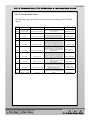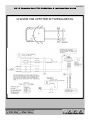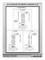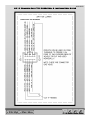
1
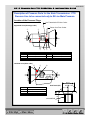
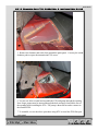
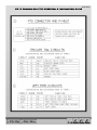
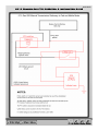
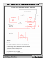
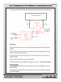
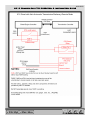
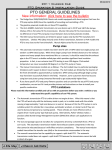
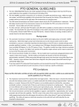
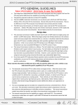
2010 Chassis Cab PTO Operation & Installation Guide
09/01/2009
PTO Operation
The 3500/4500/5500 Dodge
Ram Chassis Cab vehicle, when equipped with either the
automatic Aisin 6spd or manual G-56 6spd transmissions, will allow for an aftermarket
upfit with a transmission driven PTO (power take off). The customer will have the ability
to operate the PTO in either a “stationary” or “mobile” mode. The vehicles will be
factory set to the “stationary” mode. In order to select the “mobile” mode a Chrysler
Group LLC Dealership is required to modify the vehicles settings using their proprietary
Dealer service tool.
Stationary Mode
To operate the PTO in this mode the vehicle must meet the following conditions:
• Be in “park” position ( vehicles equipped with automatic transmission)
• Upfitter provider (on/off) switch has been activated
• Parking brake applied (vehicles equipped with manual transmission)
• Vehicle must be running
• No vehicle, brake or clutch switch faults present
• PTO must be correctly installed using the vehicle provided circuits
The customer has the choice to operate the PTO by utilizing the cruise control switches
or by utilizing a remote control (provided by the PTO supplier). To operate the feature
using the cruise control switches the customer must first activate the up fitter provided
on/off switch. Next, the cruise control “on” switch is selected. Following this step the
“set” switch must be depressed. The vehicle is now in the PTO mode and is ready for use.
In order to increase or decrease the engine idle speed, to optimize the PTO function, the
“accel” and “decel” cruise switches can be used respectively.
To disengage PTO operation and return to “standard vehicle operation” simply turn the
up fitter provided on/off switch to the off position.
To operate the PTO via a remote switch the customer must make sure the above
conditions are met. It is vital for proper operation that the PTO and remote have been
installed correctly paying special attention to ensure the vehicle provided wiring has been
connected properly. This is the responsibility of the installer of the PTO and
switches/remote system. It is the responsibility of the PTO manufacturer to ensure that
their electrical (switches and remote) system is compatible with the vehicle’s electrical
architecture and software functionality.
Mobile Mode
To operate the PTO in this mode the vehicle must meet the following conditions:
• Dealer selected “mobile” mode activated via Dealer proprietary service tool
• Upfitter provider (on/off) switch has been activated
• Vehicle must be in “park” or “drive” position (vehicles equipped with automatic
transmission)
ALL
+
-
IN
OUT
2010 Chassis Cab PTO Operation & Installation Guide
09/01/2009
• Parking brake must not be applied
• No vehicle, brake or clutch switch faults present
• Vehicle must be running
• PTO must be correctly installed using the vehicle provided circuits
The customer may choose to use the PTO while the vehicle is moving. To do so the PTO
function must be activated prior to taking the vehicle out of “park”. This is accomplished
by activating the up-fitter provided PTO on/off switch. At this point the customer may
place the vehicle in a forward or reverse gear and have PTO operation.
To disengage PTO operation and return to “standard vehicle operation” simply turn the
up fitter provided on/off switch to the off position.
NOTE: For application specific information with respect to PTO and pump requirements
and additional vehicle information (wiring schematics, preset idle values, engine speed
limits, and vehicle hardware and software requirements) please refer to the Dodge
Ram Body
Builders Guide by accessing “Wiring Diagrams” and choosing the appropriate links.
Cummins Feature Description (6.7L Diesel)
ECM: Engine Control Module
FCI: 10 Way Connector located @ left side bell housing (for 2007 MY only)
Idle up
I/O – ECM Pins B40 & B56
Developed to aid Cabin Heating by elevating the idle speed upon operator command
through the steering wheel mounted cruise switches.
To engage, the operator first presses the Cruise On switch. Then pressing and releasing
the Set switch. The feature engages and engine speed increases to 900 RPM.
The operator may “ramp” the engine speed up to 2000 RPM by holding the Res Accel
switch. The operator may “ramp” the engine speed down to 900 RPM by holding the
Coast switch.
When Idle Up is engaged it can be disabled several ways. The Cruise Cancel switch,
pressing the brake pedal, moving the PRNDL from Park or Neutral or vehicle speed
greater than 2 MPH will disable Idle Up.
Several calibrations are available for Idle Up. The engine speed range, max engine
torque and engine speed ramp rate for example.
ALL
+
-
IN
OUT
2010 Chassis Cab PTO Operation & Installation Guide
09/01/2009
Stationary PTO
I/O – ECM B16 – FCI Conn pin 9
Circuit K425
This feature interacts with the transmission to utilize an auxiliary shaft to drive
equipment. Activated by a switch inside the cab, this feature operates only when the
vehicle is stationary. The input is switched to ground.
Once active, the engine speed increased by holding the RES ACCEL button on the
steering wheel or decreased by holding the COAST button.
Stationary PTO is available only when the vehicle is stationary. When the truck is
equipped with an automatic transmission, it must be in Park and the service brake must
be released and functional. When the truck is equipped with a manual transmission, the
Parking Brake must be Set and the service brake must be released and functional.
Remote PTO
I/O ECM Pin B18 – FCI Conn pin 7 Circuit F425
This feature interacts with the transmission to utilize an auxiliary shaft to drive
equipment. Activated by a switch outside of the cab, this feature operates only when the
vehicle is stationary. The input is switched to ground.
Once active, the engine speed is changed when the switch changes from Off (open
circuit) to On (closed to ground) or toggled in less than ½ second. Toggling the switch
On-Off-On triggers the engine to change to the next calibrated engine speed. This can be
repeated for up to five engine speed settings. Repeated toggles cycles through the engine
speed 1-2-3-4-5-1-2 and so on.
Remote PTO feature has a higher priority than Idle Up. If the Remote PTO feature is
active the Idle Up switches are ineffective. The Idle Up or Stationary PTO feature cannot
be activated until the Remote PTO relinquishes control
Mobile PTO
Enabled via the StarScan unit at the Dealer
This feature interacts with the transmission auxillary shaft. The feature is activated by a
switch (closed to ground) in the cab after selected by a service tool. When active, this
feature limits engine speed and road speed to calibrated values.
When this feature is selected stationary PTO and Remote PTO features are not available.
ALL
+
-
IN
OUT
2010 Chassis Cab PTO Operation & Installation Guide
09/01/2009
Remote Throttle and Remote Throttle Switch
I/O:
Remote Throttle Switch – ECM B8 – FCI conn Pin 4
Remote Throttle Signal – ECM B37 – FCI conn Pin 3
Remote Throttle 5 Volt Supply – ECM B27 – FCI conn Pin 1
Remote Throttle Sensor Return – ECM B28 – FCI conn Pin 2
Circuit K129
Circuit K128
Circuit K854
Circuit K400
This feature allows the user of a continuously variable throttle. This throttle
potentiometer is power by the 5 volt supply and sensor return lines provided.
This feature is activated when the Remote Throttle Switch is On (closed to ground) and
the main throttle is closed. Remote Throttle does not require idle validation switches and
is not to be used for main vehicle accelerator.
*MUST BE ENABLED BY DODGE DEALER!
Accelerator Interlock
I/O – ECM B17 – FCI conn Pin 6 Circuit K810
This feature disables accelerator control of the engine speed when indicates a desired
condition. The desired condition is indicated by a switch closed to ground.
Switch Return
I/O – ECM B33 – FCI conn Pin 8 Circuit V937
Electrical return/ground for switch circuits.
Number of Remote PTO Speed Settings
Total number of engine speed selections available to Remote PTO feature 5.
Electrical Connection to the Vehicle at Bell Housing
The vehicle wiring provides an easy access point to connect your PTO. For the 2007
model year vehicles there is a 10 way connector located on the left side of the vehicle
near the bell housing of the transmission. For 2008 and beyond the connector has been
removed leaving only the blunt cut wires with heat shrink tubing on the ends. For all
model years the circuits are in the same location. The circuits at this location along with
the circuits found near the brake booster and inside the vehicle are provided for PTO
integration to the vehicle’s electrical system.
ALL
+
-
IN
OUT
2010 Chassis Cab PTO Operation & Installation Guide
09/01/2009
LEARNING SET SPEED
NOTE: This Feature Requires Engine Calibration Software released in December
2008:
If your vehicle was produced before December 2008, you must have the dealer “Reflash”
the engine controller to December 2008 or later engine software.
In order for this feature to work the PTO MUST be wired as REMOTE PTO (pto
switch between F425 and V937) not standard PTO.
¾
¾
¾
¾
¾
¾
¾
Key ON (Engine not running)
Press and release Cruise SET button 5 times within 10 seconds
Start Engine (Engine Running)
Go into IDLEUP Mode (Cruise ON then SET to go to 900 RPM)
Set the desired speed (using cruise switches)
Press Cancel
Turn Engine Off and Remove Key
UNLEARNING SET SPEED
¾ Key ON (Engine not run)
¾ Press and release Cruise Set button 5 times within 10 seconds.
Note: To LEARN a new speed, first UNLEARN the old speed
¾ Once the idle speed is LEARNED, the engine will go to that idle speed whenever
the Remote PTO switch is turned on, without additional operator assistance.
¾ PTO will engage first and then the idle speed will ramp up to the LEARNED
speed, thus not violating the AISIN requirement of not allowing PTO engagement
above 1000 RPM.
¾ The LEARNED speed is saved at power down.
NEW
INFORMATION
ALL
+
-
IN
OUT
2010 Chassis Cab PTO Operation & Installation Guide
09/01/2009
Description of Pressure Ports for the Aisin Transmission. PTO
Pressure Line to be connected only to #9 Line Main Pressure.
Location of the Pressure Plugs
Hot Transmission Fluid to Cooler
Right Side Veiw (Passenger side)
Return Line From Cooler
③
②
①
⑦ ⑥ ⑤ ④
①
②
③
④
Torque Converter Out (to Cooler)
B1 (Brake No1) Pressure
B2 (Brake No2) Pressure
L/U (Lock Up Clutch) Pressure
⑤
⑥
⑦
C1 (Clutch No1) Pressure
C2 (Clutch No2) Pressure
C3 (Clutch No3) Pressure
Left Side Veiw (Driver side)
⑧
⑨
⑩
Hole Detail (All)
⑧
Lubrication
⑨
Line (Main) Pressure
⑩
Torque Converter In (from Cooler)
φ14.1
12°
45°
2.5
15
1/2-20UNF-2B
ALL
+
-
IN
OUT
2010 Chassis Cab PTO Operation & Installation Guide
09/01/2009
PTO Troubleshooting
In response to many questions to the body builder’s hotline about correctly wiring PTO
systems, the Dodge
Ram Truck Commercial team has created this troubleshooting guide.
Wiring Types
Dodge Trucks have used three different types of PTO wiring on our chassis cab models.
Referring to the schematic diagrams, all Diesel models have common locations for: PTO
ground Z914 (black) and PTO 12V power F922 (pink/red) these are always located as
blunt cut wires in the engine compartment above the master cylinder on the dash panel.
On the Diesel automatic the K427 (Orange/Green) wire which becomes a ground when in
PTO mode is also always located in this same area.
The V937 (Violet/Brown) and K425 (Pink/Yellow) are the two wires which when
connected send and receive the signal to enter PTO mode. These wires are in three
different locations depending on date of build.
1. 2007 Model Year (3500 Models only): these two wires are in a ten pin connector
located on a bracket attached to the left hand side of the transmission bell housing
above and rearward of the starter motor. It is a separate connector that contains
an empty ‘dummy’ connector that can be removed to allow connection of the
mating connector on some PTO manufacturers wiring harnesses.
2. 2008 Model Year (All 3500/4500/5500 Models) Built from September 2007 until
December 15, 2007 have the following condition: There are two K425
(Pink/Yellow) wires above the master cylinder area. Simply tie these two wires
together and connect them to the mating wire on the PTO harness.
There are also two (Violet/Brown) wires but only one is V937. They are located
as blunt cut wires at the left side of the bell housing above the starter motor. Only
one of these wires is the correct V937 wire. To determine the correct wire you
must test for voltage with the key in the on position. The correct wire has zero
volts. The incorrect wire has five volts. Connect the wire with the zero volt
reading to the mating wire on the PTO harness.
3. 2008 Model Year (All 3500/4500/5500 Models) Built after January 1, 2008 have
the K425 (Pink/Yellow) and V9237 (Violet/Brown) wires available in the upfitter
jumper that comes in the plastic bag. This connects to the mating connector
located at the dash panel between the brake and park brake pedals where the main
engine to instrument panel wiring harness goes through the dash panel.
PTO System Test
Below are two methods to test the truck’s idle up and PTO mode systems. This is helpful
to confirm that the truck software is correctly configured and that the PTO mode still
correctly functions.
It is possible that an incorrect connection during the PTO installation process can set a
fault code in the powertrain control module and disable the PTO mode until the fault is
cleared at the dealer.
ALL
+
-
IN
OUT
2010 Chassis Cab PTO Operation & Installation Guide
09/01/2009
Method one.
With the vehicle idling, in park, turn on the cruise control switch and then press the set
button. The engine speed should immediately increase to 900 RPM. If it does not, there
is an issue with the idle up/PTO mode.
Method Two.
With the vehicle idling in park connect the V937 and the K425 wires described above.
The engine speed should immediately increase to 900RPM. If it does not, you are either
using the incorrect wires or there is an issue with the idle up/PTO mode.
PTO Usage with Remote Start
If the PTO is being used in conjunction a remote start device, the PTO switch must be
turned off and then turned back on after each restart. To automate this function, many
upfitters have been adding a timer function to the remote start logic that turns on the PTO
switch after 10-15 seconds.
ALL
+
-
IN
OUT
2010 Chassis Cab PTO Operation & Installation Guide
09/01/2009
PTO Installation Alternative
In addition to the current method of PTO installation from beneath the vehicle, an
alternative method has been developed that allows the installation from above by
removing the PTO patch panel in the floor. The instructions are as follows.
1. Remove the rear package tray located behind the seat from the vehicle.
2. Unbolt the seat and move it to the rear of the cabin where the package tray was
removed.
3. Remove the sill guards (rocker panel covers) passenger side to allow the vinyl
floor mat to be lifted. They are removed by prying straight up to disengage metal
clips.
4. Lift the floor mat and fold it rearward and toward the drivers side to expose the
patch panel
ALL
+
-
IN
OUT
2010 Chassis Cab PTO Operation & Installation Guide
09/01/2009
5. Remove the fasteners and sealer from around the patch panel. Cut away the sound
deadener pad to expose the transmission PTO access.
6. You are now able to install and assemble the PTO and pump through the opening.
Note: larger pumps must be inserted through the hole and moved toward the rear of
the opening before installing the PTO. The pump is then slid forward to connect to
the installed PTO.
7. To assemble, reverse the above procedure using RTV to reseal the PTO floor pan
patch panel.
ALL
+
-
IN
OUT
2010 Chassis Cab PTO Operation & Installation Guide
09/01/2009
PTO Circuit Definition Chart
The following chart is provided to assist in correctly interfacing the PTO with the
vehicle:
Circuit
Name
Type/Gauge/Color
Circuit Functionality
K854F
18T - VT/BR - for 2007
18T-DG- for 2008
remote throttle 5 volt supply
K400E
18T - BR/VT
K128
18T - DB/WT
Description
5 volt pwr supply to the remote potentiometer
(remote's control power circuit). Supplied by the
engine controller
Remote's ground (ground to the potentiometer
of remote). Supplied by the engine controller.
remote throttle sensor return (gnd)
Do not hook to other grounding location
Remote signal sent to the engine controller.
remote throttle signal
Signal from the remote's potentiometer.
K129
18T - DB/DG
remote throttle switch
K119
18T - LG/BK
Maximum engine speed limit
K810
18T - VT/DG
Accelerator interlock
F425
18T - PK
Remote PTO Swicth
V937C
18T - VT/BR
Cruise control switch return
K425
18T - OR/BR - for 2007
18T-PK/YL - for 2008
PTO switch
On/Off switch provided by customer to "turn
on/off remote function. Remote switch closes to
ground. Connect ground side of switch to pin #8
in this connector. Do not ground to vehicle.
Feature selects a lower maximum engine speed
when switch is "on". Switch closes to ground.
Customer supplied switch.Connect ground side
of switch to pin #8 in this connector. Do not
ground to vehicle.
Usage
Remote throttle control
Remote throttle control
Remote throttle control
Remote throttle control
Max operating speed
switch
Disable accelerator control of engine by closing
an operator installed switch. This switch closes
to ground. Connect ground side of switch to pin
#8 in this connector. Do not ground to vehicle. Customer supplied switch
Customer supplied remote PTO on/off switch.
Switch closes to ground. Connect ground side
of switch to pin #8 in this connector. Do not
Remote PTO
ground to vehicle.
Electrical ground for switch circuits. Ground
returns to the engine controller. Do not hook to
Master ground for all
other grounding location. All customer supplied added PTO switches. Do
PTO switches ground to this pin. Please make
not apply any "dirty"
appropriate protected splice.
grounds to this location.
Circuit switches to ground using operator
installed switch. Connect ground side of switch
to pin #8 in this connector. Do not ground to
Stationary PTO
vehicle.
ALL
+
-
IN
OUT
2010 Chassis Cab PTO Operation & Installation Guide
09/01/2009
CHASSIS CAB UPFITTER KIT WIRING DETAIL
ALL
+
-
IN
OUT
2010 Chassis Cab PTO Operation & Installation Guide
09/01/2009
Location B Wiring
ALL
+
-
IN
OUT
2010 Chassis Cab PTO Operation & Installation Guide
ALL
09/01/2009
+
-
IN
OUT
2010 Chassis Cab PTO Operation & Installation Guide
ALL
09/01/2009
+
-
IN
OUT
2010 Chassis Cab PTO Operation & Installation Guide
09/01/2009
5.7L Gas G56 Manual Transmission Stationary in Cab and Mobile Mode
ALL
+
-
IN
OUT
2010 Chassis Cab PTO Operation & Installation Guide
09/01/2009
6.7L Diesel Electric Air Shift with G56 Manual Transmission
ALL
+
-
IN
OUT
2010 Chassis Cab PTO Operation & Installation Guide
09/01/2009
6.7L Diesel PTO with G56 Manual Transmission Stationary Remote Preset Mode
ALL
+
-
IN
OUT
2010 Chassis Cab PTO Operation & Installation Guide
09/01/2009
6.7L Diesel PTO with G56 Manual Transmission Stationary and Mobile Mode
ALL
+
-
IN
OUT
2010 Chassis Cab PTO Operation & Installation Guide
09/01/2009
6.7L Diesel with Aisin Automatic Transmission in Cab Stationary and Mobile Mode
ALL
+
-
IN
OUT
2010 Chassis Cab PTO Operation & Installation Guide
09/01/2009
6.7L Diesel with Aisin Automatic Transmission Stationary Remote Mode
ALL
+
-
IN
OUT