1
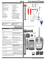
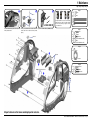
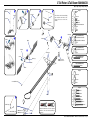
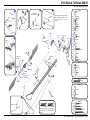
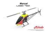
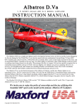
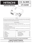
Manual www.mikado-heli.de LOGO 500 DX • LOGO 500 3D LOGO 600 DX • LOGO 600 3D Mikado Modellhubschrauber • Friedrich-Klausing-Straße 2 • 14469 Potsdam • Germany phone +49 (0)331 23749-0 • fax +49 (0)331 23749-11 • www.mikado-heli.de © Mikado Modellhubschrauber, V1.1 Index Tools for Assembly & R/C Equipment Manual for Mikado helicopter models LOGO 500 DX, LOGO 500 3D, LOGO 600 DX and LOGO 600 3D Safety Instructions. . . . . . . . . . . . . . . . . . 2 Tools for Assembly & R/C Equipment. . . . . . . . 2 1 Mainframe. . . . . . . . . . . . . . . . . . . . . 3 2 Tail Rotor & Tail Boom 500/600 DX. . . . . . . . . 4 3 Tail Rotor & Tail Boom 500 3D. . . . . . . . . . . 5 4 Tail Rotor & Tail Boom 600 3D. . . . . . . . . . . 6 5 Main Gear & Tail Rotor Assembly. . . . . . . . . 7 6 Swashplate . . . . . . . . . . . . . . . . . . . . . 8 7 Radio . . . . . . . . . . . . . . . . . . . . . . . . 9 8 Servo Installation . . . . . . . . . . . . . . . . . 10 9 Rotor Head 500 DX/3D. . . . . . . . . . . . . . 11 10 Rotor Head 600 DX/3D. . . . . . . . . . . . . . 12 11 V-Bar Rotor Head 500 3D. . . . . . . . . . . . 13 12 V-Bar Rotor Head 600 3D. . . . . . . . . . . . 14 13 Rotor Head Assembly. . . . . . . . . . . . . . 15 14 Mounting the Motor. . . . . . . . . . . . . . . . 15 Radio and Battery. . . . . . . . . . . . . . . . 16 Decal and Canopy Mounting. . . . . . . . . . . 17 RC Programming. . . . . . . . . . . . . . . . . 18 Rotor Blades. . . . . . . . . . . . . . . . . . . 19 Pre-Flight Check. . . . . . . . . . . . . . . . . 20 Operation During Flight . . . . . . . . . . . . . 21 Upgrades. . . . . . . . . . . . . . . . . . . . . 22 Overview Chassis. . . . . . . . . . . . . . . . 23 Overview Tail Rotor LOGO 500/600 DX . . . . . 24 Overview Tail Rotor LOGO 500 3D. . . . . . . . 25 Overview Tail Rotor LOGO 600 3D. . . . . . . . 26 Overview Rotor Head LOGO 500. . . . . . . . 27 Overview Rotor Head LOGO 600. . . . . . . . 28 Overview V-Bar Head LOGO 500/600. . . . . . Note: There is no bag 4. The bags are numbered 1 to 12, with the exception of 4. Max. rotorhead rpm LOGO 500: 2100 U/min Max. collective range: +/- 12° Keep in mind that other people around you might also be operating a R/C model. Never use a frequency which someone else is using at the same time. Radio signals will be mixed and you will lose control of your model. If the model shows irregular behavior, bring the model to a halt immediately. Turn off all power switches and disconnect the batteries. Investigate the reason and fix Screwdrivers (plus and minus) Grease Ball link pliers circlips pliers Scissors Pitch Gauge Rubber Hammer Hex Wrenches 1.5/2.0/2.5/3.0 mm (.055/.079/.098/.118 in) Max. rotorhead rpm LOGO 600: 2000 U/min Max. collective range: +/- 12° Safety Instructions OPERATING YOUR MODEL SAFELY Operate the helicopter in spacious areas with no people nearby. !Warning: Do NOT operate the helicopter in the following places and situations (or else you risk severe accidents): • in places where children gather or people pass through • in residential areas and parks • indoors and in limited space • in windy weather or when there is any rain, snow, fog or other precipitation If you do not observe these instructions you may be held reliable for personal injury or property damage! Always check the R/C system prior to operating your helicopter. When the R/C system batteries get weaker, the operational range of the R/C system decreases. Note that you may lose control of your model when operating it under such conditions. Threadlock 15 16 17 18 20 20 20 21 22 23 24 25 26 27 28 the problem. Do not operate the model again as long as the problem is not solved, as this may lead to further trouble and unforeseen accidents. ! Warning: In order to prevent accidents and personal injury, be sure to observe the following: Before flying the helicopter, ensure that all screws are tightened. A single loose screw may cause a major accident. Replace all broken or defective parts with new ones, as damaged parts lead to crashes. Never approach a spinning rotor. Keep at least 10 meters/yards away from a spinning rotor blades. Do not touch the motor immediately after use. It may be hot enough to cause burns. Perform all necessary maintenance. PRIOR TO ADJUSTING AND OPERATING YOUR MODEL, OBSERVE THE FOLLOWING !Warning: Operate the helicopter only outdoors and out of people’s reach as the main rotor operates at high rpm! ! Warning: While adjusting, stand at least 10 meters/ yards away from the helicopter! Novice R/C helicopter pilots should always seek advice from experienced pilots to obtain hints with assembly and for pre-flight adjustments. Note that a badly assembled or insufficiently adjusted helicopter is a safety hazard! In the beginning, novice R/C helicopter pilots should always be assisted by an experienced pilot and never fly alone! Alle shown products are examples. You may use different brands. V-Bar Speedcontroller BEC, replaces receiver battery Motor + Speed Controller (check the Mikado webpages for recommended motors) Fast Charger Radio with Heli-Software Receiver Manual The New Generation - ©Mikado Modellhubschrauber - Page 1 Mainframe Bag 1 • Bag 6 • Bag 10 • Bag 12 Bag 1 14x 3x17 M2,5 4x 3x 3x7x3 LOGO 600 3D You may install the four servos into the main frame either now or later. If you wish to install the servos now, please go to page 10, before you continue here. Using the rod M2.5x60, position all 14 nylon nuts Before you combine the two sides of the main Spacers for 25 mm tail boom (LOGO 600 3D). frame, attach the two belt tensioners (#4089, in the right side frame. bag 6). M2,5 SW5x59 1x M2,5x60 Bag 6 2x 4x 3x17 3x5x2,5 2x M2,5x8 (LOGO 500 DX/3D, LOGO 600 DX) 10x19x5 2x M2,5 (LOGO 500 DX/3D, LOGO 600 DX) Bag 10 4x M2,5x8 2x 10x19x5 Bag 12 LOGO 500DX & 600 DX: 4x 14x M2,5x10 4x M3x10 4x 5 4 3x7x3 M2,5x16 M2,5x16 (4x) All parts shown in the boxes are displayed in real size. Manual The New Generation - ©Mikado Modellhubschrauber - Page 2 Tail Rotor & Tail Boom 500/600 DX Bag 5 • Bag 6 • Bag 9 • Bag 10 • Bag 11 M3x14 6x10x2,5 M2x8 2x8 3x4x10 Bag 5 2x7 5x10x0,1 1x If the tail rotor shaft shows axial play after closing the two halves of the tail rotor case, use one or two of the washers. M3x20 2x 2x 1x 1x 1x 5x10x0,1 2x7 3x4x10 M2x8 Kugel/ball/Rotule Ø4,8x2 2x 3x5x2 5x 1x M3 M3x3 M3 Stopp 7 M3x3 M3x25 M3x3 Bag 6 (LOGO 500 DX) 2x Kugel/ball/Rotule Ø4,8x3 2x Kugel/ball/Rotule Ø4,8x2,5 2x 4x 2x M3 Stopp 3x5x2 M3 Stopp LOGO 500DX: 1x LOGO 600 DX: 2x 3x8x3 M3 Bag 6 (LOGO 600 DX) 5x10x4 M3x16 2x8 Kugel/ball/Rotule Ø4,8x3 M3 4x Bag 9 (LOGO 500 DX) M2,5x30 4x Bag 9 (LOGO 600 DX) M3x30 M3x12 Bag 10 2 mm ball links (2x) 2x 6x10x2,5 2x 5x10x4 4x 3x8x3 Bag 12 2x M3x30 8 1x 2x 1x 2x 5 Min. Epoxy 2,5 mm ball links (4x) 2x LOGO 600 DX: LOGO 500 DX: M3x12 M3x14 M3x16 M3x20 M3x25 M3x30 Attach the ball links so that the engraved number is on the outer surface pointing towards you. Manual The New Generation - ©Mikado Modellhubschrauber - Page 3 Tail Rotor & Tail Boom 500 3D Bag 5 • Bag 6 • Bag 9 • Bag 10 • Bag 11 Countersunk screw M2x8 M3x14 M2x8 Bag 5 2x8 2x7 3x5x5 3x6x2,5 5x10x0,1 If the tail rotor shaft shows axial play after closing the two halves of the tail rotor case, use one or two of the washers. 6x10x2,5 1x 2x8 2x 1x 1x 2x 5x10x0,1 M2x8 Ø4,8x2 2x7 1x 1x 1x 3x5x5 M2x8 Ø4,8x2 1x 3x5x0,5 M3x20 3x12 7 2x 3x6x2,5 M3 Stopp M3x3 M3x25 5x10x4 M3x3 M3 Stopp M3x16 5x8x0,5 2x M2,5x6 2x 2,5x6x0,5 2x 4x8x3 2x 4x8x2 2x 2x Large inner diameter 3x5x0,5 5x 1x 1x M3x16 4x8x3,5 M3 M3x3 3x12 Bag 6 4x8x3 Small inner diameter M3 Stopp 4x8x2 2,5x6x0,5 5x8x0,5 Apply grease to bearing M2x6 2x Ø4,8x3 2x Ø4,8x2,5 2x 1x M3 M2x6 1x M2 Bag 9 M2,5x30 6x M2,5x6 M2 8 Bag 10 M3x30 2x 6x10x2,5 2x 5x10x4 4x 3x6x2,5 Bag 12 1x 5 Min. Epoxy 1x Attach the ball links so that the engraved number is on the outer surface pointing towards you. 2x 2x M3x14 M3x20 M3x25 M3x30 Manual The New Generation - ©Mikado Modellhubschrauber - Page 4 Tail Rotor & Tail Boom 600 3D Bag 5 • Bag 6 • Bag 9 • Bag 10 • Bag 11 Bag 12 1x Countersunk screw M2x8 M3x14 M2x8 M3x8 2x M3x40 2x7 3x5x5 3x6x2,5 M3x14 2x 2x8 Bag 5 1x 5x10x0,1 (2x) 5x 6x10x2,5 M3x35 If the tail rotor shaft shows axial play after closing the two halves of the tail rotor case, use one or two of the washers. 3x5x0,5 M3x35 (5x) 7 2x M3x8 3x5x10 M2,5x6 Large inner diameter Small inner diameter 5x10x0,1 M2x8 Kugel/ball/Rotule Ø4,8x2 2x7 1x 1x 1x 3x5x5 M2x8 Kugel/ball/Rotule Ø4,8x2 2x SW5x26,5 5x6x2 M3x3 2x 1x 1x 2x 1x 3x6x2,5 M3 Stopp (5x) 3x5x0,5 5x8x0,5 2x M2,5x6 2x 2,5x6x0,5 2x 4x8x3 2x 4x8x2 2x 5x13x4 2x M3x16 5x 1x 1x 4x8x3 4x8x2 M3 Stopp 5x8x0,5 M2x6 Apply grease to bearing 2,5x6x0,5 M2,5x6 M2 2x8 4x8x3,5 M3 M3x3 3x12 2x M2,5x6 2x 3x5x10 2x Ball Ø6 mm M3x16 5x6x2 1x 4x 5x26,5 Kugel/ball/Rotule Ø6x3 Bag 6 2x 1x M3x40 1x M3 M2x6 M2 Bag 9 M2,5x30 2x Bag 10 8 9 2x 6x10x2,5 5 Min. Epoxy 5 Min. Epoxy M2,5x30 (6x) M2,5x30 (2x) Ball Ø6 mm Attach the ball links so that the engraved number is on the outer surface pointing towards you. 2x 4x 5x13x4 3x6x2,5 Manual The New Generation - ©Mikado Modellhubschrauber - Page 5 Main Gear & Tail Rotor Assembly Bag 2 • Bag 8 • Bag 12 LOGO 500 3D LOGO 500 DX Bag 2 1x 4x M3x8 2x 10x16x0,2 10x16x0,5 LOGO 500 3x 1x 3x 1x M2,5x8 (LOGO 500 3D) Bag 8 LOGO 600 10x16x0,5 3x16 M4x5 (LOGO 500 DX) 4x M3 Bag 12 4x 10x16x0,5 LOGO 500 DX/3D = 2x LOGO 600 3D = 1x M2,5x20 M3x20 (LOGO 600 DX/3D) 2x (LOGO 600 3D) M3x10 M3x20 (4x) M3x8 M3 Stopp (4) Grease autorotation hub M3x10 Check direction of rotation of the tail rotor! See page 20, item no. 3. M3x10 10x16x0,5 8 use super glue to fix position Tighten tooth belt: Pull tail boom backwards and tighten screws Manual The New Generation - ©Mikado Modellhubschrauber - Page 6 Swashplate Bag 3 • Bag 10 500 DX 600 DX Tighten the pivot bolts very carefully. Do not overtighten them, as they will break off. (4x) Bag 3 2x 2x 2x 4x 2x 4x 4x M2x8 4x 2x 3 mm 3x11 M2x10 2x Tighten the pivot bolts very carefully. Do not overtighten them, as they will break off. (7x) Bag 3 3x11 3 mm 2x 2x Kugel/ball/Rotule 4,8 3 mm 500/600 3D 3 mm M2x8 2x 2x Kugel/ball/Rotule 2x 2x Bag 10 4x 3x5x2,1 2x Kugel/ball/Rotule Ø4,8x7 2x Bag 3 3x11 2x 2x (7x) 3x7x3 M3x14 3x5x0,5 M2x8 Kugel/ball/Rotule 2x Manual The New Generation - ©Mikado Modellhubschrauber - Page 7 Radio JR/Graupner Throttle CH1 JR/Graupner with Virtual Flybar Rudder Air Speed Sensor Aileron right Aileron CH2 CH3 Elevator CH3 Aileron left V-Bar Mainboard CH2 CH4 CH1 CH2 CH3 Bluetooth Modul Elevator Rudder CH4 3-axis Gyro CH1 Throttle Pitch CH5 Futaba/Hitec Aileron CH1 Elevator CH2 Futaba with Virtual Flybar for Futaba G3 receiver check the V-bar manual Rudder Air Speed Sensor Aileron right CH3 V-Bar Mainboard Bluetooth Modul Rudder CH4 Aileron left CH2 Elevator CH1 CH4 CH6 CH1 CH2 Throttle CH3 3-axis Gyro Throttle Pitch CH5 Manual The New Generation - ©Mikado Modellhubschrauber - Page 8 Servo Installation Bag 1 • Bag 9 • Bag 12 LOGO Rotor Head (V-Stabi, flybarless head) 16 mm 16 mm 16 mm 4 14 mm Bag 9 4x 1x M2x10 M2x12 4x 2,9x13 (4x) LOGO Rotor Head (with flybar) 20 mm 20 mm 20 mm 9x 3x If you are installing Futaba servos, add the distance plate for the two aileron servos. 14 mm 5 Bag 1 12x 2x M2 M3x30 Bag 12 4x 3x5x2 2x 1x Bag 1 LOGO 500 DX 2x 1x 2 M2,5x10 (4x) 3x5x7 M2,5x10 Bag 1 LOGO 600 3D Bag 1 LOGO 500 3D 2x 1x M3x55 2,9x13 M2x14 3x5x1 M3x45 Bag 1 LOGO 600 DX 1x M3x45 M3x65 LOGO 500 DX 6 LOGO 500 3D LOGO 600 3D (4x) LOGO 600 DX 2,9x13 (4x) 9 7 Aileron left Aileron right Elevator Rudder M2x14 3 Use M2x14 15 mm 39 mm Attach the ball links so that the engraved number is on the outer surface pointing towards you. 45 mm Apply a small amount of oil to the rotor shaft. Manual The New Generation - ©Mikado Modellhubschrauber - Page 10 9 Rotor Head 500 DX/3D Bag 7 • Bag 10 • Bag 12 M2x8 3x5x12 500 3D 3x7x3 Small inner diamenter Large inner diameter M4 8x11x1 M3x25 4x 3x7 2x 2x 8x14x4 3x7x0,5 M2x8 4,8 3x5x12 (LOGO 500 3D) 2x 4x Apply grease to bearing 3x5x16 8x 2x More agility 4x12x1 Bag 7 4x M3x25 M2x8 500 DX M4x25 10x14x0,5 M4x12 Less agility 2x30 2x 3x5x16 (LOGO 500 DX) 3x7x0,5 (LOGO 500 DX) 3x7 8x11x1 2x30 10x14x1 2x 0° A 500 3D LOGO 500 3D 0° A A=B A=B B 2x 2x B 4x 4x 5 M2x10 2x4,5x0,5 M2x12 M3x3 small amount of grease incorrect M2 M3x3 2x 2x 4,8 2x4,5x0,5 500 DX M2x12 M4 M2x3 4x 4x10x4 ball bearing (LOGO 500 3D) 4x10x4 slide bearing (LOGO 500 DX) M4x25 Bag 10 4x OK 4x13x5 4x10x4 (LOGO 500 DX) M2x10 2x M2x8 incorrect 4x12x1 M2x3 4x 4x 2x 2x M3x3 M4x12 2x 8x14x4 3x7x3 (LOGO 500 3D) 4x13x5 2x 4x10x4 (LOGO 500 3D) 2x 6x14x5 Bag 12 2x M3x25 Manual The New Generation - ©Mikado Modellhubschrauber - Page 11 10 Rotor Head 600 DX/3D Bag 7 • Bag 10 • Bag 12 M3 Stopp 3x5x12 600 3D M2x8 M5x12 M4x35 10x14x1 8x 4,8 3x5x12 (LOGO 600 3D) 2x 4x Small inner diamenter Large inner diameter M4 Stopp 3x8 3x5x16 (LOGO 600 DX) 3x7x0,5 (LOGO 600 DX) 4x 3x8 2x 2x 8x11x0,5 8x11x0,5 Apply grease to bearing 3x5x16 M3x35 8x16x5 2x30 2x30 3x7x0,5 2x 0° A M2x8 2x 5x15x1 M2x8 Bag 7 4x M3x35 3x7x3 M3 Stopp 600 DX 0° 11,5x15,8x1 2x LOGO 600 3D M5x12 A A=B A=B B B 2x 2x 4x M2x12 2x4,5x0,5 M2x10 (4x) 5 M3x3 4x 4x 2x M2 M3x3 2x 2x 4,8 2x4,5x0,5 2x M2x8 small amount of grease M2 5,3x15x1 M2x3 M2x10 M2x12 M4 2x M4x35 Bag 10 incorrect incorrect OK 4x 4x13x5 3x7x3 (LOGO 600 3D) M2x3 600 3D 4x10x4 ball bearing (LOGO 600 3D) 4x10x4 slide bearing (LOGO 600 DX) 4x 8x16x5 2x Bag 12 600 DX 2x 2x M3x35 2x 8x16x5 5x13x5 4x10x4 (LOGO 600 3D) Manual The New Generation - ©Mikado Modellhubschrauber - Page 12 11 V-Bar Rotor Head 500 3D Bag 7 M3x8 (5x) Bag 7 Apply grease to bearing 5x M3x8 8x14x4 (5x) Small inner diameter Large inner diameter 4x12x1 6x 3x8 2x 8x11x0,5 4x 8x14x4 2x M3x10 10x14x1 M4x12 2x 6x14x5 10x14x1 2x 5 3x12 3x7x3 6 M3x10 1x M3x20 2x M3x22 2x M4x12 M3 Stopp M3x20 45 mm 2x M3x22 2x 7 3x5x0,3 M3x14 3x6x2,5 2x 3x5x2 1x M4x25 4x12x1 M3 2x 2x 2x 9 M4 Ø4,8x3 3x12 4x 3x7x3 4x 3x6x2,5 2x 3x5x2 2x 1x M3x5 2x 8 M3x14 M3x5 3x5x0,3 Please adjust the swashplate driver in such a way that the balls on the inner and outer ring of the swashplate are positioned exactly on a line along the longitudinal axis of the heli. Manual The New Generation - ©Mikado Modellhubschrauber - Page 13 12 V-Bar Rotor Head 600 3D Bag 7 M3x8 (5x) Apply grease to bearing Small inner diameter Bag 7 5x M3x8 8x14x4 Large inner diameter (5x) 6x 3x8 2x 8x11x0,5 4x 8x16x5 2x M3x10 8x16x5 10x14x1 M4x12 2x 5 3x12 3x7x3 6 11,5x16x1 2x M3x10 1x M3x20 2x 2x 45 mm M3 Stopp M3x20 3x5x0,3 M5x12 2x M3x22 2x 7 M3x14 M3x35 3x6x2,5 M4x35 3x5x2 2x 3x 5x15x1 M3 2x 9 2x 2x M3x5 M4 Ø4,8x3 3x12 4x 3x7x3 4x 3x6x2,5 2x 3x5x2 2x 1x 8 2x M3x14 M3x5 3x5x0,3 Please adjust the swashplate driver in such a way that the balls on the inner and outer ring of the swashplate are positioned exactly on a line along the longitudinal axis of the heli. Manual The New Generation - ©Mikado Modellhubschrauber - Page 14 Apply a small amount of grease to the contact surface 13 Rotor Head Assembly 14 Mounting the Motor Bag 7 • Bag 12 Bag 1 • Bag 12 1 Bag 7 1x Bag 1 M3 2x Bag 12 1x Bag 12 M3x18 2x 2 For very hard 3d flying counterbearing no. #4134 (5 mm) or #4148 (6 mm) should be installed. Please goto page 28. Antenna tube 3 3x9x1 available pinions for module 0.5 diameter 5 mm (not included in kit) 17 teeth* #4117 18 teeth* #4118 19 teeth* #4119 20 teeth* #4120 21 teeth* #4121 22 teeth* #4122 23 teeth* #4123 M3x14 Installation of the Motor Pinion Screw the motor pinion onto the motor shaft, making sure that it can still be moved. Now mount the motor on the motor plate and move the pinion so it is aligned well with the main gear. As visual help for aligning the pinion you may use the small ridge which separates the two parts of the pinion. When the pinion is aligned correctly it will easily engage with the main gear. If the pinion does not engage with the main gear, it is not correctly aligned. After the pinion is correctly aligned, take the motor out of the mainframe and tighten the set screw. Gear Backlash Move the motor with the pinion until it is limited by the gear. Tighten one of the M3x14 screws slightly. You must still be able to swivel the motor around its own axis. In this way you can easily determine the correct distance between the main gear and the pinion. There should be no (!) gear backlash. At the same time, the motor should not (!) exert any pressure onto the running surface of the main gear. After you have determined the correct distance, tighten the second M2x14 screw. available pinions for module 0.7 diameter 5 mm (not included in kit) 12 teeth* #4212 13 teeth #4213 14 teeth #4214 15 teeth #4215 16 teeth #4216 17 teeth #4217 18 teeth #4218 19 teeth #4219 available pinions for module 0.7 diameter 6 mm (not included in kit) 15 teeth #4315 16 teeth #4316 17 teeth #4317 18 teeth #4318 *for max. to 6S LiPo Manual The New Generation - ©Mikado Modellhubschrauber - Page 15 15 Radio and Battery Bag 1 • Bag 10 Position of servo arms for the tail rotor when sticks are centered 3 Position for mounting tail gyro 3 Position for mounting V-Bar gyro 4 Position of servo arms for the aileron servos when sticks are centered (0 deg. Pitch) Receiver 5 V-Bar Main board 7 6 speed controller 8 Battery: Attach the battery with O-rings and Velcro. Rings (2x) Position of LiPo battery for the power supply of receiver. Velcro Manual The New Generation - ©Mikado Modellhubschrauber - Page 16 16 Decal and Canopy Mounting Bag 1 Mounting the Decal onto the Canopy Use a scissors to cut out the individual elements of the decal pattern. Make sure that you leave a small edge (1 to 2 mm) at the rim. Corners should be cut out with a small radius to avoid unwanted peeling off. Attach the individual elements of the pattern in the following way: Prepare a bowl of water with a small amount of dish washing detergent. Apply some of this water to a cloth or fill up a squirt bottle with it. Using the cloth or squirt bottle, wet the surface of the canopy and the sticking surface of the decal element. Place the decal onto the canopy. You can still move the decal at this point. When you have found the correct position, use a hair dryer to secure the pattern. Be careful not to hold the dryer to close to the decal, as it will shrink if too much heat is applied. Bag 1 4x shorten cap 3x5x4 4x 3x5x10 2x M3x8 2x M3x30 Bag 1 + 12 2x 2x 3x5x4 M3x8 shorten cap Manual The New Generation - ©Mikado Modellhubschrauber - Page 17 17 RC Programming 120° Swashplate Mixing (120° CCPM) The LOGO swashplate is designed to be controlled via electronic CCPM. Thus the corect control inputs of the three swashplate servos are automatically mixed by the R/C transmitter. If you have never programmed 120° CCPM before, please read this introductory text carefully. Minimum Pitch Collective (Pitch) Pitch function is used to control the lift or sink of the helicopter. When pitch input is given, all three swash-plate servos travel together in the same direction and the same amount. As a result the swash-plate moves up or down on an even level. Maximum Pitch Aileron (Roll) the two roll servos (in the front of the swashplate) travel in Aileron (roll) is used to control the helicopter’s movements opposite directions. As a result the swash-plate tilts to the around its longitudinal axis. When aileron (roll) input is given, right or to the left. Roll to the right 17 RC Programming Programming 120° CCPM As the programming procedure varies with different types of R/C systems, it is necessary for you to refer to the instruction manual of your R/C system. Here are only a few general guidelines which apply to most systems. Servo Centering with Sub-Trim Function As indicated in the above sections on mounting the servos, it is important that the servo arms are exactly centered. You should use the servo sub-trim function of your R/C system for this purpose. Activating 120° CCPM Likely, the 120° CCPM function is initially disabled in your R/C transmitter software and needs to be separately activated. Please refer to your R/C system manual, where you will also find information on which channels should be used for the elevator servo and the two roll servos. It is important that you stick with the requirements stated in the manual. Otherwise the 120° CCPM will not function properly. Your R/C may support various different CCPM mixings. For the LOGO choose the 120° mixing with two roll servos in the front and one elevator servo in the back. Use the relevant menus for setting the mixing proportions for roll, elevator and pitch functions. Begin by setting the mix values to 50% each. Higher mix values give higher servo travel for that function This can have the unwanted result that the swashplate reaches its mechanical limits and causes damage to the servos or rods or to the swashplate. Roll to the right (view from rear) Elevator (Tilt) For tilting the helicopter, use the elevator function. For tilting backward elevator servo moves upward. The elevator servo forward, the two aileron servos move downward and the moves twice as much as the two aileron servos. All servos travel the same distance at maximum deflection Increase servo travel of elevator servo on one side Setting Pitch Values Please choose from two different pitch settings, depending on your flying style. The two settings are illustrated below. The standard range is for beginners and for pilots who will do some aerobatic flight without extended periods of inverted flight. The final pitch values must be tested during test flying. Once Elevator forward If necessary, you may use the CCPM menu to reverse the direction of the function. This is necessary, for example, if the swashplate tilts to the wrong side or the pitch function is inverted. The menu for reversing servo functions can be used for reversing the movements of individual servo arms, but not for reversing the entire control function and of all the involved servos. Servo Travel It may be the case that all swash-plate servos do not travel the same distance at maximum deflection. Even small differences between the 3 servos can prevent the swash-plate from being level during collective pitch inputs and cause the heli to drift. In order to correct such servo travel differences, you must increase or decrease the servo travel setting accordingly. Use the menu ATV for adjusting the end points, if necessary. Do not get this menu mixed up with Dual/Rate. (Dual/Rate menu allows using multiple servo travel ranges and toggling between them during flight.) Example: If during maximum pitch the elevator servo travel is slightly smaller than travel of the two aileron servos, then the swashplate will be tilted backwards, causing the heli also to drift backwards. In this case you should increase the travel of the elevator servo. set, the values will work with the rotor blades you used. In case you change over to a different set of rotor blades, the pitch values will have to be adjusted to the properties (size, profile etc.) of the new set. Elevator forward (view from side) Manual The New Generation - ©Mikado Modellhubschrauber - Page 18 17 RC Programming Pitch Values The center position of the sticks in your R/C radio corresponds to 0° pitch of the rotor blades. At 0° pitch, all levers (servo arms, washout lever, mixing arms) should be in horizontal position. At 0° pitch, the swashplate is in center position, allowing the same travel in upward (positive pitch) and downward (negati- Application Standard ve pitch) direction. This setting results in a linear pitch curve, which is ideal for 3D-style flying. Pilots who wish to fly with less negative pitch should reduce the pitch curve to approx. -3° pitch. Note that with this latter set-up the sticks are not at center position for hovering. Low Pitch Hovering (Stick Centered) High Pitch – 3º 7º to 8º 11º to 12º 3D Low Pitch Stick Centered High. Pitch – 10º bis – 12º 0º 11º to 12º Minimum Pitch 0° - Pitch For setting the respective pitch values, please use a pitch gauge. The values for minimum and maximum can be specified in the menus of the transmitter. Aileron and Elevator Travel The travel range of the aileron and elevator servos are limited by the swash-plate’s mechanical limits. Please take care that the swash-plate does not hit the maximum of its travel. This can have the unwanted result that the swashplate reaches its mechanical limits and causes damage to the servos or rods to the swash-plate itself. If you desire more agility for your helicopter, use lighter flybar paddles. In case the servo travel is too small, you have the following options for correcting this: 1. Move the ball end of the tail rotor servo further away from the center of the servo arm. 2. Increase the servo travel in your R/C system using ATV. 3. Increase the servo travel in your gyro (not all gyros have this option). Ensure that the tail rotor servo turns in the correct direction. If necessary, reverse the direction of the tail rotor servo function in your R/C system. Adjust the tail rotor linkage in length such that the tail rotor servo arm and the tail rotor lever are at 90 with respect to each other. All parts serving the tail rotor movements must move smoothly. When there is too much resistance, the tail rotor will not react to subtle input and the gyro’s maximum sensitivity cannot be fully exploited. If you are an experienced pilot and plan on flying inverted, select the 3D settings: Application 17 RC Programming Revo-Mix/Gyro It is necessary to compensate for the torque created by the motor during flight (but not during autorotation). This compensation is done by adjusting the tail rotor pitch. There are two options for achieving this: 1. Using normal gyro mode Please refer to your R/C system manual for activating the revolution mixing function and for setting all parameters correctly. Final settings should be trimmed during test flights.2. Using a gyro in Heading-Hold mode The Heading-Hold gyro mode compensates automatically the deviation caused by the motor torque. Therefore, if Heading-Hold mode is used, revo-mix should not be programmed additionally. Important: Check to ensure that the tail rotor assembly moves smoothly and without play. Otherwise the gyro and servo will not compensate the torque properly. Rotor Head RPM control LOGO is designed to be flown with constant rotor head speed. Irrespective of flight attitude (ascending, descending, hovering), rotor speed should be kept roughly constant. There are two different methods for obtaining constant rotor speed: Rotor speed control with speed controller All speed controllers can be used in this mode. With speed controller it is necessary to program a throttle curve (see manual). Programming of throttle curve requires that you associate a given throttle value with a particular pitch value. In this way, the rotor speed is held almost constant with all pitch values. Throttle curve programming depends on the type and quality of the R/C system. Simpler, inexpensive R/C systems designed for model helicopters usually have a 3-point throttle curve. High-end R/C systems typically have throttle curves with more configurable points (up to 9). Fine tuning of throttle curves will be necessary during test flights. Note that an incorrectly programmed throttle curve reduces performance and can lead to overheating of the motor and the speed controller. Rotor speed control with governor (RPM regulation mode) A speed controller with governor function keeps the rotor head speed constant, independent of flight attitude (ascending, descending, hovering). It is not necessary to program a throttle curve. The head speed is simply controlled on the radio transmitter using a switch or lever. Important: 1) Governor mode must be activated in the speed controller first (see manual of the speed controller) 2) In governor mode, the servo wire of the speed controller must not be connected to the throttle channel. Use a free channel in your radio to connect the servo wire. Maximum Pitch Tail rotor settings When the servo arm of the tail rotor servo is in the center, the tail rotor lever and the servo arm should be perpendicular with respect to each other. The tail rotor pitch lever should never reach its mechanical limits. In case the servo travel is too large, you have the following options for correcting this: 1. Move the ball end of the tail rotor servo closer to the center of the servo arm. 2. Reduce the servo travel in your R/C system using ATV. 3. Reduce the servo travel in your gyro (not all gyros have this option). Manual The New Generation - ©Mikado Modellhubschrauber - Page 19 18 Rotor Blades 19 Pre-Flight Check Carbon Rotor Blades Rotor blades made from glass-fiber-enhanced plastic or carbon are typically in ready-to-fly condition when new. It will only be necessary to adjust blade tracking. Wooden Rotor Blades Balancing of Rotor Blades (Center of Gravity) Place each rotor blade over an edge as shown in picture (1). Adjust the blades so that they are in equilibrium. If the center of gravity is not in the same place in each blade, this needs to be corrected using tape. Apply as much tape as necessary until both blades show their center of gravity in the same place. moving low by unscrewing the ball links somewhat. Repeat the checking procedure until both rotor blades move on the same level. Static balancing Screw the rotor blades together as shown in picture (2). The rotor blades are properly balanced when they are suspended exactly horizontally. If one of the rotorblades is not exactly horizontal, the blades are not in equilibrium. This is corrected by applying tape to lighter blade. When mounting the rotor blades to the blade holders, note the proper direction (clockwise rotation). Tighten the cap screws holding the rotor blades, so that the blades cannot move easily in the blade holders. 20 Operation During Flight Rudder Pitch/Throttle Direction of Main and Tail Rotation Prior to the first flight, you must re-check the direction of rotation of the main rotor head and the tail rotor! 4 3 4 3 You may want to program a different stick mode than the one shown. Please check which stick mode is used by other local pilots. Use the same one, so fellow pilots can assist you on the field. Important: Flying a model helicopter requires many Blade Tracking Adjustment hours of training. During your first attempts, while familiarizing yourself with the different control movements, keep the helicopter low above the ground (just a few centimeters/a couple of inches.) Aileron Elevator 3 Incorrect Prior to the first flight the tracking of the rotor blades needs to be adjusted. If the tracking is not adjusted properly, this can cause vibrations and lead to instability of the helicopter. Apply colored tape to the tip of one of the rotor blades. Apply tape of a different color to the tip of the other rotor blade. When you are ready for your first flight, increase the rotor 4 O.K. speed to just before lift-off. From a safe distance, check the rotor disk at eye-level. Very likely, one rotor blade will move below the other. Make a note of the color of the low-moving blade. Then turn off the motor and wait until the rotor head has come to a halt. Lengthen the linkage (1) of the rotor blade which was 3 4 Manual The New Generation - ©Mikado Modellhubschrauber - Page 20 21 Upgrades Canopy holders #3038 Carbon rotor blades 500 mm #2712 Carbon rotor blades 550 mm #1049 Carbon rotor blades 600 mm #1048 Alu motor plate #4088 Hardened main rotor shaft #4075 Hardened tail rotor shaft #2475 Carbon vertical fin LOGO 500 DX / 3D #2780 LOGO 600 DX #2493 Carbon horizontal fin LOGO 500 DX / 3D #2781 LOGO 600 DX #2494 Tail rotor hub with trust bearing #4069 Rotor disk #932 Clamp ring #2385 Heavy flybar paddles #2358 Light flybar paddles #2359 Tail servo holder #828 Dumper rubber set extra hard #3092 Alu washout unit #973 Carbon tail rotor upgrade #3062 Alu swashplate #2364 Mixing arms ball raced #4001 Washout fully ball-raced #970 Washout fully ball-raced with alu hub #971 Tail rotor lever ball-raced #2447 V-Bar #4010 V-Bar with pressure sensor #4011 Glass-fiber canopy LOGO 500 3D #4109 Manual The New Generation - ©Mikado Modellhubschrauber - Page 21 22 Overview Chassis LOGO 500 3D Canopy #4111 LOGO 500 3D Decal #4083 LOGO 500 DX Canopy #4112 LOGO 500 DX Decal #4082 LOGO 600 DX Canopy #4114 LOGO 600 DX Decal #4084 LOGO 600 3D Canopy #4130 LOGO 600 3D Decal #4085 Manual The New Generation - ©Mikado Modellhubschrauber - Page 22 23 Overview Tail Rotor LOGO 500/600 DX Manual The New Generation - ©Mikado Modellhubschrauber - Page 23 24 Overview Tail Rotor LOGO 500 3D Manual The New Generation - ©Mikado Modellhubschrauber - Page 24 25 Overview Tail Rotor LOGO 600 3D Manual The New Generation - ©Mikado Modellhubschrauber - Page 25 26 Overview Rotor Head LOGO 500 Manual The New Generation - ©Mikado Modellhubschrauber - Page 26 27 Overview Rotor Head LOGO 600 Manual The New Generation - ©Mikado Modellhubschrauber - Page 27 28 Overview V-Bar Head LOGO 500/600 For very hard 3d flying counterbearing no. #4134 (5 mm) or #4148 (6 mm) should be installed. Install bolt only if motorshaft does not reach the ball bearing. M3x35 cut to 14 mm length www.mikado-heli.de Construction & Rendering: Mehran Mahinpour Tirooni • Layout & Realisation: CDT-Berlin Manual The New Generation - ©Mikado Modellhubschrauber - Page 28