1
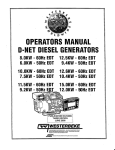
OPERATORS MANUAL
0-NET DIESEL GENERATORS
22.0 KW EDE·:.&OHz 17.0 KW EDE·.&O:Hz
17.. 0 KW EDE ·50.Hz 13.5 KW EDE-50 Hz
Single 31J
ree Phase
PUBLICATION NO. 053852
REVISION 4
DECEMBER 2012
~
WESTERBEKE
WESTERBEKE CORPORATION • 150 JOHN HANCOCK ROAD
MYLES STANDISH INDUSTRIAL PARK • TAUNTON MA 02780
WEBSITE: WWW. WESTERBEKE.COM
----
IVMMA Member National Marine Manufacturers Association
A
wARNING
Exhaust gasses contain Carbon Monoxide, an odorless and
colorless gas. Carbon Monoxide is poisonous and can cause
unconsciousness and death. Symptoms of Carbon Monoxide
exposure can include:
•Dizziness
• Throbbing in Temples
•Nausea
• Muscular Twitching
•Headache
• Vomiting
• Weakness and Sleepiness •Inability to Think Coherently
IF YOU OR ANYONE ELSE EXPERIENCE ANY OF THESE SYMPTOMS,
GET OUT INTO THE FRESH AIR IMMEDIATELY. If symptoms persist,
seek medical attention. Shut down the unit and do not restart
until it has been inspected and repaired.
A WARNING DECAL is provided by
WESTERBEKE and should be fixed to a
bulkhead near your engine or generator.
WESTERBEKE also recommends installing
CARBON MONOXIDE DETECTORS in the
living/sleeping quarters of your vessel.
They are inexpensive and easily
obtainable at your local marine store.
CALIFORNIA
PROPOSITION 65 WARNING
Marine diesel and gasoline engine
exhaust and some of its constituents
are known to the State of California
to cause cancer, birth defects,
and other reproductive harm.
SAFETY INSTRUCTIONS
INTRODUCTION
PREVENT BURNS - FIRE
Read this safety manual carefully. Most accidents are
caused by failure to follow fundamental rules and
precautions. Know when dangerous conditions exist and
take the necessary precautions to protect yourself, your
personnel, and your machinery.
The following safety instructions are in compliance with
the American Boat and Yacht Council (ABYC) standards.
•
PREVENT ELECTRIC SHOCK
•
A WARNING: Fire can cause injury or death!
A WARNING: Do not touch AC electrical connections
•
while engine is running, or when connected to shore
power. Lethal voltage is present at these connections!
•
•
Do not operate this machinery without electrical
enclosures and covers in place.
•
Shut off electrical power before accessing electrical
equipment.
•
Use insulated mats whenever working on electrical
equipment.
•
Make sure your clothing and skin are dry, not damp
(particularly shoes) when handling electrical equipment.
•
Remove wristwatch and all jewelry when working on
electrical equipment.
•
Do not connect utility shore power to vessels AC
circuits, except through a ship-to-shore double throw
transfer switch. Damage to vessels AC generator may
result if this procedure is not followed.
•
Electrical shock results from handling a charged
capacitor. Discharge capacitor by shorting terminals
together.
PREVENT BURNS - HOT ENGINE
•
A WARNING: Steam can cause injury or death!
•
In case of an engine overheat, allow the engine to cool
before touching the engine or checking the coolant.
diesel fuel will bum.
A WARNING: Explosions from fuel vapors can cause
injury or death!
•
Follow re-fueling safety instructions. Keep the vessels
hatches closed when fueling. Open and ventilate cabin
after fueling. Check below for fumes/vapor before
running the blower. Run the blower for four minutes
before starting your engine.
•
All fuel vapors are highly explosive. Use extreme care
when handling and storing fuels. Store fuel in a
well-ventilated area away from spark-producing
equipment and out of the reach of children.
Do not fill the fuel tank(s) while the engine is running.
Shut off the fuel service valve at the engine when servicing
the fuel system. Take care in catching any fuel that might
spill. DO NOT allow any smoking, open flames, or other
sources of fire near the fuel system or engine when
servicing. Ensure proper ventilation exists when servicing
the fuel system.
•
•
exhaust system components. A running engine gets
very hot!
Always check the engine coolant level at the coolant
recovery tank.
Be aware -
PREVENT BURNS - EXPLOSION
A WARNING: Do not touch hot engine parts or
•
Prevent flash fires. Do not smoke or permit flames or
sparks to occur near the carburetor, fuel line, filter, fuel
pump, or other potential sources of spilled fuel or fuel
vapors. Use a suitable container to catch all fuel when
removing the fuel line, carburetor, or fuel filters.
Do not operate without a Coast Guard Approved flame
arrester. Backfire can cause severe injury or death.
Do not operate with the air cleaner/silencer removed.
Backfire can cause severe injury or death.
Do not smoke or permit flames or sparks to occur near
the fuel system. Keep the compartment and the
engine/generator clean and free of debris to minimize the
chances of fire. Wipe up all spilled fuel and engine oil.
•
•
Do not alter or modify the fuel system.
Be sure all fuel supplies have a positive shutoff valve.
•
Be certain fuel line fittings are adequately tightened and
free of leaks.
•
Make sure a fire extinguisher is installed nearby and is
properly maintained. Be familiar with its proper use.
Extinguishers rated ABC by the NFPA are appropriate
for all applications encountered in this environment.
SAFETY INSTRUCTIONS
ACCIDENTAL STARTING
TOXIC EXHAUST GASES
A WARNING: Accidental starting can cause injury
A WARNING: Carbon monoxide (CO) is a deadly gas!
or death!
•
•
Disconnect the battery cables before servicing the engine/
generator. Remove the negative lead first and reconnect
it last.
Make certain all personnel are clear of the engine before
starting.
•
•
Ensure that the exhaust system is adequate to expel gases
discharged from the engine. Check the exhaust system
regularly for leaks and make sure the exhaust
manifolds/water-injected elbow is securely attached.
Be sure the unit and its surroundings are well ventilated.
Run blowers when running the generator set or engine.
•
Make certain all covers, guards, and hatches are
re-installed before starting the engine.
•
Do not run the generator set or engine unless the boat is
equipped with a functioning marine carbon monoxide
detector that complies with ABYCA-24. Consult your
boat builder or dealer for installation of approved
detectors.
•
For additional information refer to ABYC T-22
(educational information on Carbon Monoxide).
BATTERY EXPLOSION
A WARNING: Battery explosion can cause injury
or death!
•
•
Do not smoke or allow an open flame near the battery
being serviced. Lead acid batteries emit hydrogen, a
highly explosive gas, which can be ignited by electrical
arcing or by lit tobacco products. Shut off all electrical
equipment in the vicinity to prevent electrical arcing
dming servicing.
A WARNING: Carbon monoxide (CO) is an invisible
odorless gas. Inhalation produces flu-like symptoms,
nausea or death!
•
Never connect the negative(-) battery cable to the
positive (+) connection terminal of the starter solenoid.
Do not test the battery condition by shorting the terminals
together. Sparks could ignite battery gases or fuel vapors.
Ventilate any compartment containing batteries to prevent
accumulation of explosive gases. To avoid sparks, do not
disturb the battery charger connections while the battery
is being charged.
•
Avoid contacting the terminals with tools, etc., to prevent
bums or sparks that could cause an explosion. Remove
wristwatch, rings, and any other jewelry before handling
the battery.
•
Always tum the battery charger off before disconnecting
the battery connections. Remove the negative lead first
and reconnect it last when disconnecting the battery.
•
•
Although diesel engine exhaust gases are not as toxic as
exhaust fumes from gasoline engines, carbon monoxide
gas is present in diesel exhaust fumes. Some of the
symptoms or signs of carbon monoxide inhalation or
poisoning are:
Vomiting
Inability to think coherently
Dizziness
BATTERY ACID
Headache
Nausea
A WARNING: Sulfuric acid in batteries can cause
Throbbing in temples
Muscular twitching
Weakness and sleepiness
AVOID MOVING PARTS
severe injury or death!
•
Do not use copper tubing in diesel exhaust systems. Diesel
fumes can rapidly destroy copper tubing in exhaust
systems. Exhaust sulfur causes rapid deterioration of
copper tubing resulting in exhaust/water leakage.
Do not install exhaust outlet where exhaust can be drawn
through portholes, vents, or air conditioners. If the engine
exhaust discharge outlet is near the waterline, water could
enter the exhaust discharge outlet and close or restrict the
flow of exhaust. Avoid overloading the craft.
A WARNING: Rotating parts can cause injury
When servicing the battery or checking the electrolyte
level, wear rubber gloves, a rubber apron, and eye
protection. Batteries contain sulfuric acid which is
destructive. If it comes in contact with your skin, wash it
off at once with water. Acid may splash on the skin or
into the eyes inadvertently when removing electrolyte
caps.
or death!
•
..
II
Do not service the engine while it is running. If a
situation arises in which it is absolutely necessary to
make operating adjustments, use extreme care to avoid
touching moving parts and hot exhaust system
components .
SAFETY INSTRUCTIONS
•
Do not wear loose clothing or jewelry when servicing
equipment; tie back long hair and avoid wearing loose
jackets, shirts, sleeves, rings, necklaces or bracelets that
could be caught in moving parts.
•
Make sure all attaching hardware is properly tightened.
Keep protective shields and guards in their respective
places at all times.
•
Do not check fluid levels or the drive belts tension while
the engine is operating.
•
Stay clear of the drive shaft and the transmission coupling
when the engine is running; hair and clothing can easily
be caught in these rotating parts.
ABYC, NFPA AND USCG PUBLICATIONS FOR
INSTALLING DIESEL ENGINES
Read the following ABYC, NFPA and USCG publications
for safety codes and standards. Follow their
recommendations when installing your engine.
ABYC (American Boat and Yacht Council)
"Safety Standards for Small Craft"
Order from:
ABYC
3069 Solomon's Island Rd.
Edgewater, MD 21037
NFPA (National Fire Protection Association)
"Fire Protection Standard for Motor Craft"
Order from:
HAZARDOUS NOISE
A WARNING: High noise levels can cause hearing
NFPA
11 Tracy Drive
Avon Industrial Park
Avon, MA02322
loss!
•
•
Never operate an engine without its muffler installed.
Do not run an engine with the air intake (silencer)
removed.
•
Do not run engines for long periods with their enclosures
open.
USCG (United States Coast Guard)
"USCG 33CFR183"
Order from:
U.S. Government Printing Office
Washington, D.C. 20404
A WARNING: Do not work on machinery when you are
mentally or physically incapacitated by fatigue!
OPERATORS MANUAL
Many of the preceding safety tips and warnings are repeated
in your Operators Manual along with other cautions and
notes to highlight critical information. Read your manual
carefully, maintain your equipment, and follow all safety
procedures.
GASOLINE ENGINE AND GENERATOR INSTALLATIONS
Preparations to install an engine should begin with a
thorough examination of the American Boat and Yacht
Council's (ABYC) standards. These standards are a
combination of sources including the USCG and the NFPA.
Sections of the ABYC standards of particular interest are:
H-2 Ventilation
P-1 Exhaust Systems
P-4 Inboard Engines
E-9 DC Electrical Systems
All installations must comply with the Federal Code of
Regulations (FCR).
Engines & Generators
iii
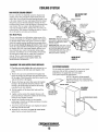
INSTALLATION
When installing WESTERBEKE engines and generators it is important that strict
attention be paid to the following information:
CODES AND REGULATIONS
Strict federal regulations, ABYC guidelines, and safety codes must be complied with
when installing engines and generators in a marine environment.
SIPHON-BREAK
For installations where the exhaust manifold/water injected exhaust elbow is close to
or will be below the vessel's waterline, provisions must be made to install a siphonbreak in the raw water supply hose to the exhaust elbow. This hose must be looped a
minimum of 20" above the vessel's waterline. Failure to use a siphon-break when
the exhaust manifold injection port is at or below the load waterline will result in
raw water damage to the engine and possible flooding of the boat.
If you have any doubt about the position of the water-injected exhaust elbow relative
to the vessel's waterline under the vessel's various operating conditions, install a
siphon-break.
NOTE: A siphon-break requires periodic inspection and cleaning to ensure proper
operation. Failure to properly maintain a siphon-break can result in catastrophic
engine damage. Consult the siphon-break manufacturer for proper maintenance.
AVAILABLE FROM
YOUR WESTERBEKE
OEALER
EXHAUST SYSTEM
SIPHON-BREAK WITH STAINLESS
LOOP FOR 1" HOSE
PART NO. 044010
The exhaust hose must be certified for marine use. The system must be designed to
prevent water from entering the exhaust under any sea conditions and at any angle
of the vessels hull.
A detailed Marine Installation Manual covering gasoline and diesel
engines and generators is supplied with every unit sold. This manual
.Is also available in pdf format on our website to download
Website: www.westerbeke.com
Engines & Generators
iv
TABLE OF CONTENTS
Parts Identification oo ........................................................... 2
Introduction ......................................................................... 3
Fuel, Engine Oil and Engine Coolant... ............................... s
Preparations for Initial Start-Up ......................................... 6
Digital Control Panel .................................... oo ..................... 7
LCD Sequence ...................................................................... 8
Digital Control Panei ........................................................ SA-B
Remote Stop/Start Panel ......................... ,........................... 9
Generator Break-In Procedure .......................................... 1o
Daily Routine ..................................................................... 1o
Maintenance Schedule (Chart) ......................................... 11
Fuel System ....................................................................... 13
Cooling System ........................... ,...................................... 15
Raw Water Intake Strainer. ........................................ l5
Raw Water Cooling Circuit... ..................................... IS
Heat Exchanger ........ oo ................................................ 16
Raw Water Pump ....................................................... 16
Fresh Water Cooling System ...................................... l7
Changing the Coolant... .............................................. 17
Air Intake/Silencer ..................................................... 18
Thermostat. .. :.................................... :......................... 18
Engine Lubricating Oil ....................................... oo.oo ........... l9
Engine Oil Change.oo .. oooooo .. oooooooo ... oooooooooooooo••oo•oo .. oooo .. l9
Testing Oil Pressure 00.00 .. oo• oo· 00 00 00 0000 00 ..... 00 00 0000 ... 00 0000 00 0020
Remote Oil Filter (optional)oooooooooooooo000ooooooooooooooooo .. oo.21
Wiring Diagrams .......... oo .. oooo···oo····oo·oo·· .. ·oo······oooo ............ :.. 22
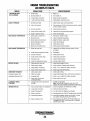
Engine Troubleshooting (Chart) ooooooooooooooooooooooooooooooooooooooo.23
LCD Display Faults ooOOOOOOooOOOO 0000000000 .. oooooo .. oo ... oo oooo .. oo 00 .. oo ..... 24
Alternator Testing oooooooo .. oooooooooo.oo.oooooo00000000oooooooo .. ooooo ... oo ... 25
Battery Care .... 0000 oo .. oooo .... oooo .. oo. oo· .. oooo .. oo oooo· 000000
21
Engine Adjustments ... oo ........... oo ........ 00000000000000. oo· .. 00 00 ........ 28
Valve Adjustments ...... oo ......... oo ................................... 28
Glow Plugs .... 00 ..... 00 ........................... 00 ................ ···oo .. 29
Drive Belt Adjustment .......... 0000 ........... 00 ................ 00 .. 29
Fuel Injectors ................ oo .... ooooo,.oooo•oo··· ....................... 29
Fuel Injectors .............. 00 ....... 00 ......... oo••oooo ........... oo ....... oooo .. 30
Injection Testing 00 oo·oo·. 00.00 oooooooooooo·oo oooo•oooo .... oo 00 0000000000.30
Starter Motor oooooooo·oooo·oooo·oooo.oooo. 0000 00 .oo oo ... oo ... oooo. oooo•oo·oo· .. oo .31
Troubleshooting .... oo ............... oo····oo·oo·····oo·······-oooo······-31
Emergency Start oo·oo·oooooooooooooooooo .. oo.ooooooo-oooo••oooo-oooo.oo·.32
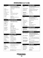
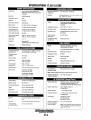
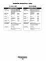
Engine/Generator Specifications ... oo·oo·oooo.oo.oooo.oooooooooooooooo33
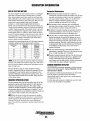
Generator lnformation ...... oo.oo•······················ ..................... 34
Electronic Regulation oo•oo•oooo•oo·oo·•oooo ........ oo .. oooo•oooooo--·oooo.35 1
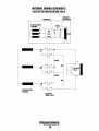
Internal Wiring Diagram 00 00. oo. oooooooo· 000000 .. 00 000000 .. 00 .. oo .. 00.0000 .. 36
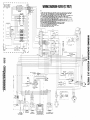
Generator Wiring Schematics oooooooooooooooooooo .. oo .. oo•oooooo·oo .. oo.37
Schematic - Rotating Field/Exciter Rotor 00000000000000000000000.38
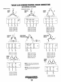
Twelve Lead Winding Connectionsoo .. oooooo ....... oooo ..... oooooooo.39
Changing Hertz and Voltage.oo .... oo .... oo .. oo .. oooo ..... oooooooooo·oo39A
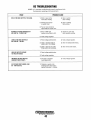
BE Troubleshooting (Chart) .oo .. oo .. oo .. oooo .. oooo .. oooo .. oo .......... oo ..40
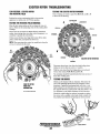
Exciter Rotor Troubleshooting oo .. oo .. oo .... oo .... oo.oo ........ oo .... oo.4l
Generator Servicing 00 oooooo .. oooo.oooo 0000. oooo· 00 .. oo.oooooo oo• oo ..... 0000 0042
Generator/Maintenance Parts Breakdown oooo ... oo .. oooooooooo ..43
Power Transfer Switch oooo .. oooooooo 00 .............................. 00 0000 ..45
Lay-Up and Recommissioning ............... 0000 .... 00 ................. .46
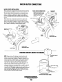
Water Heater Connections. 00 ....... 00 .. 00 .. 00 00 oo· 00 00 ... 00 .. 00 00 00 00 ... .48
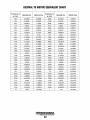
Metric Conversion Data (Chart) .. oo ....... oo .. oooooooooo-oooooo·oo .... .49
Suggested Spares. oo, oooooooooo ... oooo. oooooooo· oooo· 00 ..... 00 .... oooo·. 00. 00 .. 5 1
000000 . .
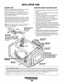
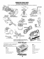
PARTS IDENTIFICATION
ECU
CONNECTIONS-~
REMOTE PANEl
CONNECTION
INTAKE
ELBOW
THER.MOSTAT
ASSEMBLY
DRIP TRAY
LEFT SIDE
FRONT
Oil FILl
COOLANT PRESSURE CAP.
INJECTION PUMP
HEAT
EXCHANGER
FUSL
AIR INTAKE
OIL FILTER
CONTROL BOX
AIR INTAKE SILENCER
DIGITAL CONTROl
PANEL
SPIN-ON
FUEL FILTER
20A
DC BREAKER
RIGHT SIDE
REAR
LEXIBLE ISOLATED
MOUNTS
Engines & Generators
2
INTRODUCTION
This WESTERBEKB Diesel Generator is a product of
WESTERBEKB's long years of experience and advanced
technology. We take great plide in the superior durability and
dependable p'erformance of our engines and generators.
Thank you for selecting WESTERBEKE.
In order to get the full use and benefit from your generator it
is important that you operate and maintain it correctly. Tllis
manual is designed to help you do tllis. Please, read tllis ·
manual carefully and observe all tlle safety precautions
throughout. Should your generator require servicing, Contact
your nearest WESTERBEKB dealer for assi~tance.
This is your operators manual. A parts catalog is also
provided and a technical manual is available from your
WESTERBEKB dealer. If you are planning to install tllis
equipment contact your WESTERBEKE dealer for
WESTERBEKE'S installation manual.
PRODUCT SOFTWARE
Your WESTERBEKE Warranty is included in a separate ·
folder. If, after 60 days of submittil;tg the Warranty Regiftry
form you have not received a customer identification card
registering your warranty, please contact the factory in
writing with model information, including the unit's serial
number and commission date.
Product software, (tech data, parts lists, manuals,
brochures and catalogs), provided from sources other than
WESTERBEKE are not witllin WESTERBEKE's control.
WESTERBEKE CANNOT BE RESPONSIBLE FOR THE
CONTENT OF SUCH SOFTWARE, MAKES NO
WARRANTIES OR REPRESENTATiuNS WITH RESPECT
THERETO, INCLUDING ACCURACY, TIMEliNESS OR
COMPLETENESS THEREOF AND WI/LIN NO EVENT
BE LIABLE FOR ANY TYPE OF DAMAGE OR INJURY
INCURRED IN CONNECTION WITH OR ARISING OUT
OF THE FURNISHING OR USE OF SUCH SOFTWARE.
WESTERBEKE custOmers should also keep in mind tile
time span between printings of WESTERBEKE product
software and the unavoidable existence of earlier
WESTERBEKE manuals. In summation, product software
provided with WESTERBEKE products, whether from
WESTERBEKE or other suppliers, must not and cannot
be relied upon exclusively as the definitive authority on
the respective product It not only makes good sense
but is imperative that appropriate representatives of
WESTERBEKE or the supplier in question be consulted
to determine the accuracy and currentness of the
product software being consulted by the customer.
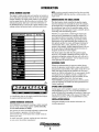
Customer. Identification Card .
NOTES, CA~TIONS AND WARNINGS
WARRANTY PROCEDURES
AB this manual takes you through the operating procedu~es,
maintenance schedules, and troubleshooting of your manne
erigine, critical information will be .highlighted by NOTES,
CAUTIONS, and WARNINGS. An explanation follows:
1"""/WESTERBEKE
I
Engines & Generators
Customer Identification
MR. GEl\TERATOR OWNER
MAIN STREET
HOMETOWN, USA
Model
Ser. #
Expires
NOTE: An operating procedure essential to ..note.
A
CAUTION: Procedures, which if not strictly
observed, can result in the damage or destruction of
your engine.
A
WARNING: Procedures, which if not properly
followed, can result in personal injury or loss of life.
Engines & Generators
3
INTRODUCTION
NOTE: A carbon monoxide warning decal has been provided
by WESTERBEKE. Affix this decal in a visible position in the
engine room.
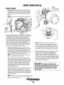
SERIAL NUMBER LOCATION
The engine's model number and serial number are located on
an I.D. plate that is mounted on the side of the water jacketed
exhaust manifold. The engine serial number is also stamped
into the engine block on the fiat surface just outboard of the
fuel injection pump. Take time to enter this information on
the illustration below. It will provide a quick reference when
seeking technical information and/or ordering needed parts.
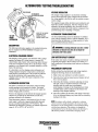
UNDERSTANDING THE DIESEL ENGINE
The diesel engine closely resembles the gasoline engine,
since the mechanism is essentially the same. The cylinders
are arranged above a closed crankcase; the crankshaft is of
the same general type as that of a gasoline engine; and the
diesel engine has the same type of valves, camshaft, pistons,
connecting rods and lubricating system.
Therefore, to a great extent, a diesel engine requires the
same preventive maintenance as a gasoline engine. The
most important factors are proper ventilation and proper
maintenance of the fuel, lubricating and cooling systems.
Replacement of fuel and lubricating filter elements at the
time periods specified is a must, and frequent checking for
contamination (that is, water, sediment, etc.) in the fuel
system is also essential. Another important factor is the use
of the same brand of high detergent diesel lubrication oil
designed specifically for diesel engines.
HZ.
The diesel engine does differ from the gasoline engine,
however, in its method of handling and firing of fuel. The
carburetor and ignition systems are done away with and in
their place is a single component - the fuel injection pump
which performs the function of both.
ORDERING PARTS
Whenever replacement/service parts are needed, always
provide the generator model number, engine serial number,
and generator serial number as they appear on the silver and
black name plate located on the generator end. You must
provide us with this information so we may properly identify
your generator set. In addition, include a complete part
description and part number for each part needed (see the
separately furnished Parts List). Also insist upon
WESTERBEKE packaged parts because will fit or generic
parts are frequently not made to the same specifications as
original equipment.
SPARES AND ACCESSORIES
Certain spares will be needed to support and maintain your
WESTERBEKE generator. Your local WESTERBEKE
dealer will assist you in preparing an inventory of spare parts.
See the SPARE PARTS page in this manual. For Engine and
Generator Accessories, see the ACCESSORIES brochure.
An identification plate on the engine manifold also displays
the engine model and setial number.
INSTALLATION MANUAL
Publication #43400 provides detailed information for
installing generators.
CARBON MONOXIDE DETECTOR
WESTERBEKE recommends mounting a carbon monoxide
detector in the vessels living quarters. Carbon monoxide,
even in small amounts, is deadly.
The presence of carbon monoxide indicated an exhaust leak
from the engine or generator or from the exhaust
elbow/exhaust hose, or the fumes from a nearby vessel are
entering your boat.
If carbon monoxide is present, ventilate the area with clean
air and correct the problem immediately!
Engines & Generators
4
DIESEL FUEL, ENGINE OIL AND ENGINE COOLANT
DIESEL FUEL
ENGINE COOLANT
USE A DIESEL FUEL WITH A CETANE RATING OF #45 OR HIGHER.
WESTERBEKE recommends a mixture of 50% antifreeze
and 50% distilled water. Distilled water is free from the
chemicals that can corrode internal engine surfaces.
(No. 2-D (SAE J313) diesel fuel according to ASTM 0975).
Care Of The Fuel Supply
The antifreeze performs double duty. It allows the engine to
run at proper temperatures by transferring heat away from
the engine to the coolant, and lubricates and protects the
cooling circuit from rust and corrosion. Look for a good
quality antifreeze that contains Supplemental Cooling
Additives (SCAs) that keep the antifreeze chemically
balanced, crucial to long term protection.
Use only clean diesel fuel! The clearance of the components
in your fuel injection pump is very critical; invisible dirt
particles which might pass through the filter can damage
these finely finished parts. It is important to buy clean fuel,
and keep it clean. The best fuel can be rendered
unsatisfactory by careless handling or improper storage
facilities. To assure that the fuel going into the tank for your
engine's daily use i~ clean and pure, the following practice is
advisable:
Purchase a well-known brand of fuel.Install and regularly
service a good, visual-type fuel filter/water separator between
the fuel tank and the engine. The Raycor 500 MA or 230
RMAM are good examples of such filters.
The distilled water and antifreeze should be premixed before
being poured into the cooling circuit.
PURCHASING ANTIFREEZE
Rather than preparing the mixture, WESTERBEKE
recommends buying the premixed antifreeze so that so that
when adding coolant the mixture will always be correct.
There are two common types of antifreeze, Ethylene Glycol
(green) and Propylene Glycol (red/purple), either can be used
but do not mix the two and if changing from one to another,
flush the engine thoroughly.
ENGINE OIL
Use a heavy duty engine oil with an API classification of CF,
CG-4, CH-4 or CI-4. Change the engine oil and filter after an
initial 50 hours of break-in operation. Then follow the oil and
filter change intervals as specified in the MAINTENANCE
SCHEDULE in this manual. Westerbeke Corporation does
not approve or disapprove of the use of synthetic oils. If
synthetic oils are used, engine break-in must be performed
using conventional oil. Oil change intervals must be as in the
MAINTENANCE SCHEDULE, not extended because
synthetic oils are used.
Premixed antifreeze for DIESEL Engines:
Specification #ASTM D53456.
MAINTENANCE
Change the engine coolant every five years regardless of the
number of operating hours as the chemical additives that
protect and lubricate the engine have a limited life.
COOLANT RECOVERY TANK
SAE OIL VISCOSITY GRADES
For all temperatures use SAE 1DW-40 or 15W-40.
OIL PRESSURE
The engine's oil pressure, during operation, is indicated
by the oil pressure gauge on the instrument panel. During
normal operation, the oil pressure will range between 35 and
65 psi 2.5 and 3.9 kg/cm2).
NOTE: A newly started, cold engine can have an oil pressure
reading upwards of60 psi (4.2 kg/cm2>. A warmed engine can
have an oil pressure reading as low as 25 psi (1.8 kg/cm2>.
These readings will vary depending upon the temperature of
the engine, the load placed on the engine, and the RPM's.
Engines & Generators
5
.
PREPARATIONS FOR INITIAL START·UP
PRESTART INSPECTION
Before starting your generator for the first time or after a prolonged layoff, check the following items:
•
Be sure that in power systems with a neutral line that
the neutral is properly grounded (or ungrounded) as the
system requires, and that the generator neutral is properly
connected to the load neutral. In single phase systems an
incomplete or open neutral can supply the wrong line-toneutral voltage on unbalanced loads.
•
Make certain the cooling water thru-hull petcock is open.
• Check the engine oil level: add oil to maintain the level at
the full mark on the dipstick.
• Check the fuel supply and examine the fuel filter/separator
bowls for contaminants.
• Check the DC electrical system. Inspect wire connections
and battery cable connections.
A CAUTION: When starting the generator, it is
recommended that all AC loads, especially large
motors, be switched OFF until the engine has come
up to speed and, in cold climates, starts to warm up.
This precaution will prevent damage caused by
unanticipated operation of the AC machinery and will
prevent a cold engine from stalling.
• Check the coolant level in both the plastic recovery tank ·
and at the manifold.
NOTE: After the initial running of the generator; the air in
the engine's cooling system will be purged to the coolant
recovery tank. Open the air bleed petcock to ensure that
the cooling system is purged of air. After shutdown and
after the engine has cooled, the coolant from the recovery
tank will be drawn into the engine's cooling system to
replace the purged air.
Before subsequent operation of the generator; the engine's
manifold should be topped off, and the coolant recovery
• Check load leads for conect connections as specified in
the wiring diagrams.
• Examine the air inlet and outlet for air flow obstructions.
• Be sure no other generator or utility power is connected to
the load lines.
KEEP 112 FULL
CLEAN THIS PASSAGEWAY
. PERIODICALLY
DIPSTICK
PUSH IN TIGHT
LOW
--_ADD OIL
Engines &
Gen~rators
6
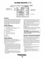
DIGITAL CONTROL PANEL
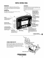
DESCRIPTION
LCD DISPLAY
WESTERBEKE' S Digital Control Panel provides the
operator with an LCD display that contunuously monitors
all the operations of the generator in easy to understand
text messages.
Operating temperatures may cause the LCD display to vary
in color. This is normal and a change.in color will not affect
the operation on the control panel.
Periodically clean the control panel LCD screen U?ing a soft
cloth.
CONTROL BOX
UP AND DOWN ARROWS
WHEN THE LCD DISPLAY IS
IN ITS SCROLL MODE, THE
UP AND DOWN ARROWS CAN
BE USED TO ADJUST THE
DARK AND LIGHT CONTRAST
Note that the design and size of the control box will vary
depending on the model generator.
UP-ARROW
WHEN IN SCROLL LOCK MODE
INDIVIDUAL FUNCTIONS CAN
BE MONITORED BY PRESSING
THE UP-ARROW.
BA FUSE
PROTECTS THE CONTROL PANEL
ELECTRONICS FROM A HIGH
AMPERAGE OVERLOAD.
SCROLL LOCK
STOPS RUN SEQUENCE SO·
THAT A SINGLE FUNCTION CAN
BE MONITORED
INDICATOR LIGHTS
SIX LIGHTS THAT INDICATE
WHERE A FAULT HAS OCCURED.
DOWN-ARROW
··WHEN IN SCROLL LOCK MODE
INDIVIDUAL FUNCTIONS CAN
BE MONITORED BY PRESSING
THE DOWN-ARROW.
~
20A BREAKE~ SWITCH""
SHUT-OFF WHEN PERFORMING
MAINTENANCE OR WHEN
REPAIRING A FAULT. RESET TO
RESTART THE ENGINE.
FAILURE LIGHT
A RED LIGHT WILL APPEAR IF
THE RUN SEQUENCE IS
INTERUPTED BY A FAILURE.
PRIME BUTTON .
START BUTTON
STARTS THE ENGINE
THISBUTTON ENERGIZES THE FUEL
PUMP. AFTER REPAIRING A FAILURE
OR PERFORMING MAINTENANCE,
PRESSING THIS BUTTON WILL PURGE
AIR OUT AND BRING FUEL IN TO THE
LINES.
LCD DISPLAY SEQUENCE
..
IS SHOWN DN THE FOLLOWING PAGE.,.
----------------------------------------------------
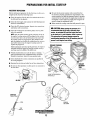
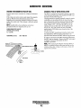
*MANUAL ENGINE SHUT-OFF
Should the stop button fail in its normal function to stop the
engine, the engine is equipped with a manual shutdown lever
located on the engine block to the right side of the injection
pump. Simply hold the lever to the left until the engine
comes to a complete stop. This shutdown lever is standard on
current D-Net generators.
7
DIGITAL CONTROL PANEL/LCD SEQUENCE
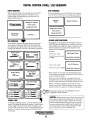
START SEQUENCE
STOP SEQUENCE
With the pre-start inspection completed, press the START
button and the automatic sequence will begin. The six
indicator lights will illuminate green and the panel will
display the following text:
To stop the generator, press the STOP button. The display
will cycle thru the following text messages and shutdown.
Shutting
Down
Waiting for operator
tw1WEST£RBEKE
Engine Shutdown
Press start to
1 Engines & Generators
engage generator
Waiting for operator
Press start to
engage generator
Pre Heating ......
7 Seconds
RUN SEQUENCE
Cranking ......
FAILURE LIGHT/SHUTDOWN
..
If a problem occurs, the generator will shutdown and the
FAILURE light will illuminate red. In addition, one of the
indicator lights will change from green to orange to reveal
where the trouble has occured and the display will text
message what has happened
,__ _ _ _ _ _ _ _.,.
Examples:
As the display cycles thru the engine functions, the speed
will come up to 1800 rpms-60Hz (1500 rpms-50Hz) and
the oil pressure and engine coolant will rise to their normal
readings. The functions will cycle in the following sequemce:
Coolant TemperaturP
Engine Speed
1800 RPM
'
2500
0
81C
32
178F
300
40
PSI
3.1
BAR
13.5 VDC
0
30
SCROLL
AC Frequency
3.8 HOURS
(/)
s
Cil
"'U
=rru
en
en
til
.r::.
a..
(])
~
f-
.r::.
SCROLL
(])
til
c:n
c:
SCROLl
600
SCROLL
AB380V.a
BC378V 0
.
CA 380.V
0
.
(jj
"d
AC Line Voltage
600
I
600
Before re-starting the generator, the 20 amp DC circuit
breaker must be reset. With the problem corrected and the
generator started, the sequences will begin cycling again.
(])
200
200
AC Phase Voltage
AB3BOVo
BC 378V 0
CA380.V 0
SCROLL LOCK
en
.r::.
a..
SCROLL
Reset ECU to Restart
There arc many combinations of messages that can be
displayed but they are all self explanatory and the operator
can easily isolate and correct the problem should one occur.
SCROLL
120V0
Low Oil Pressure
When a failure occurs, refer to the troubleshooting chart,
wiring diagram, and general operating text in this manual to
assist in solving the trouble.
100
AC Line Voltage
~~
0
co
(])
60.1Hz
0
AC Phase Voltage
A120V
B 120V 0
Oil Pressure Light is orange.
6.9
0
Engine Hours
co
Reset ECU to Restart
Failure Light is red.
100
SCROLL
..
High Engine Temp.
Oil Pressure
Battery Voltage
0
Coolant Temperature Light
is orange.
100
SCROLL
0
SC_R!)LL
. ·-
Failure Light is red.
600
I ~
600 "'U
600
¢
NOTE: Three phase voltages will vary depending on the AC
output configuration of the generator.
=rru
en
CAUTION:
•
LOCK
co
Repeated ctank cycles without a start can result
in the engine's exhaust system filling with raw water. This
raw water can enter the engine's cylinders by way of the
exhaust manifold. If after three crank cycles, the unit does
not start, drain the system's muffler and investigate and
correct the cause of no start. Engine damage, the result
of raw water entry, is not a warrantable issue.
To stop the continuing sequence, press the SCROLL LOCK
button. This enables the operator to monitor a single function
for any length of time. The word LOCK will appear in the
comer. Use the up and down an·ows to find and observe other
functions. To resume scrolling, press the SCROLL LOCK
button again.
8
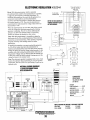
DIGITAL CONTROL BOX
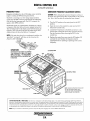
EARLIER MODELS
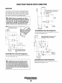
FREQUENCY FAULT
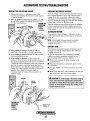
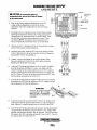
GENERATOR FREQUENCY ADJUSTMENT (HERTZ)
Frequency is displayed on the LCD display screen while the
engine is running in RPM and frequency (hertz).
The ECU is receiving a low AC voltage signal and hertz
signal from the MPU which is positioned on the bellhousing
over the flywheel ring gear teeth. The ECU interprets this
signal as both RPM and hertz.
CAUTION: When changing the generator ji·equer;cy setting on
the ECU, tum off the 20 amp DC circuit breaker on the contml
box. Tum it back on after the setting has been changed
1. Thm the DC breaker on the control panel to the OFF
position.
2. Open the cover of the control box and view the ECU
(Electronic Control Unit).
3. Locate the #1 dipswitch on the ECU and move it to the
position that con-esporids to the Hertz operation desired).
See the illustration below showing the ECU in the
conti·ol box.
Should this signal vary approximately 2% either up or down,
a frequency fault shut down will occur, initiated by the ECU.
The red failure LED on the display panel will illuminate, the
frequency LED will tum from green to amber and the LCD
display screen will show the fault text "overspeed".
NOTE: If the unit shuts down for an underspeed condition, the
same fault "overspeed" will show on the screen but the
K.
frequency LED will..
4. Replace the control box cover, tum the DC breaker ON
and start the unit. Monitor the frequency that the
engine/generator is operating is operating at the correct
frequency.
DIPSWITCHES
ECtJ CONECTIONS
LCD DISPLAY PANEL
TEST PORT
NOTE: DURING OPERATION THE COLOR
OF THE LCD DISPLAY MAY VARY.
CAUSED BY HEAT. THIS IS NORMAL
AND NO CAUSE FOR CONCERN.
CAUTION (WESTERLINK or NMEA~2000): The electronic componems in the Digital Diesels draw a very small amount of amperage (milli-amps)froni the
generators starting battery when the unit is in a static state. This maybe as much as 50 milli-amps for the system ECU and 50 milli-amps for each display.
This can be as much as 72 amp-hours in a months time with no generator use. It is not necessary to be concerned with this slight amperage draw during
normal seasonal use. However. if the generator set is not to be used for a number of months, such as willfer storage, it is best to disconnect the DC power
to the generator with a NMEA-2000 system or shut off the DC breaker on the generators control box for a WESTERLINK system.
NOTE: Keep in mind that the Westerbeke generator maybe the DC power supply for the vessel's NMEA-2000 network.
Engines & Generators
8A
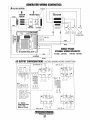
DIGITAL CONTROL PANEL
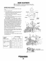
FREQUENCY FAULT
GENERATOR FREQUENCY ADJUSTMENT·(HERTZ)
Frequency is displayed·on the LCD display screen while the
engine is running in RPM and frequency (hertz).
The ECU is receiving a low AC voltage signal and hertz
signal from the MPU which is positioned on the bellhousing
over the flywheel ring gear teeth. The ECU interprets this
signal as both RPM and hertz.
1. Tum the DC breaker on the control panel to the OFF
position.
2. Open the cover of the control box and view the ECU
(Electronic Control Unit).
3. Access the opening of the ECU. The dipswitches are
visable in the elongated area of this opening.
4. Access the #1 dipswitch and move it to the position
that corresponds to the hertz operation desired. The
illustration shows these dipswitches.
5. Plug in the communications cable from your laptop
having the EC20 software. The communications cable
plug connection should have the arrow on the plug facing
the ECU connections. Reprogram the ECU for the
corresponding AC voltage output the generator is being
changed to.
6. Once the change is completed, tum OFF your laptop.
Unplug the communications cable from the ECU.
7. Proceed to page 39Aofthis manual and follow the
procedures for reconfiguring the AC voltage output of
the generator that has been selected.
· Should this signal vary approximately 2% either up or down,
a frequency fault shut down will occur, initiated by the ECU.
The red failure LED on the display panel will illuminate,- the
frequency LED will turn from green to amber and the LCD
display screen will show the fault text "overspeed".
WIRING HARNESS
CONNECTION
REMOTE PANEL
CONNECTION
~~41-711S"~f'9"....-~ECU-ELECTRONIC
CONTROL UNIT
CONTROL PANEL
NOTE: DURING OPERATION THE COLOR
OF THE LCD DISPLAY MAY VARY.
CAUSED BY HEAT, THIS IS NORMAL
AND NO CAUSE FOR CONCERN.
CONTROL BOX I
COMPONENTS
NMEA2000
T CONNECTION
CAUTION (WESTERLINK or NMEA-2000): The electronic components in the Digital Diesels draw a vel)' small amount of amperage (milli-amps) froni the
generator's starting battery whe.n the unit is in a static state. This maybe as much as 50 milli-amps for the system ECU and 50 milli-amps for each display.
This can be as much as 72 amp-hours in a months time with no generator use. It is not necessary to be concerned with this slight amperage draw during
normal seasonal use. However, if the generator set is not ro be used for a number of mollths, such as winter storage, it is best to disconnect the DC power
to the generator with a NMEA-2000 system or shut off the DC breaker on the generator's control box for a WESTERLINK system.
NOTE: Keep in mind that the Westerbeke generator maybe the DC power supply for the
vessel~·
Engines & Generators
88
NMEA-2000 network.
REMOTE STOP/START PANEL
AND EXTENSION HARNESSES
DESCRIPTION
A remote panel is available that allows the generator to be
stopped and started from any location on the boat. The
connecting harnesses ~me in three different lengths and two
of th~e can be combined for a maximum run at 75' (22.17M).
NOTE: For additionol information, contact your local
WESTERBEKE dealer.
CONNECTING EXTENSION
CABLES
6" (152.4MM)
. ·15' (4.75M)
30' (9.1M)
60' (18.2M)
REMOTE PANEL/PIG TAll
Pil 052560
~
...
PN 052959
PN 052789
PN 052960
Note: These two dimensions are the measurement of the cut-out opening.
'~5~"(68.~
Panel Box Cover Kit #053342
This kit allows for the installation of the Analog Start/Stop
switch on the generator control box and the remote meunting
of the LCD Display panel to a more visible amd accessible
location.
LCD DISPLAY EXTENSION CABLES
NMEA MICRO-C
PART NUMBER
LENGTH
053025 _ _ _1/2 MErER
053026
1 MErER
053027
2 MErER
3 MErER
053028
053029
4 MErER
5 MErER
053030
053031
. 6 MErER
053032
7 METER
053033
8 MErER
9 MErER
053034
053035
10 MErER
053061
2.2 METER
9
- 1.6 FEEr
- 3.2 FEEr
- 6.5 FEEr
- 9.8 FEEr
- 13.1 FEEr
- 16.4 FEEr
- 19.6 FEET
- 22.9 FEEr
- 26.2 FEEr
- 29.5 FEEr
-32.8 FEET
~ 40.0 FEEr
GENERATOR BREAK-IN PROCEDURE
DESCRIPTION
Although your engine has experienced a minimum of one
hour of test operations at the factory to make sure accurate
assembly procedures were followed and that the engine
· operated properly, a break-in time is required. The service
life of your engine is dependent upon how the engine is
operated and serviced during its initial hours of use.
Breaking-in a new engine basically involves seating the
piston rings to the cylinder walls. Excessive oil consumption
and smoky operation indicate that the cylinder walls are
glazed or scored, which is caused by overloading the
engine during the break-in period.
Your new engine requires approximately 50 hours of initial
conditioning operation to break in each moving part in order
to maximize the performance and service life of the engine.
Perform this conditioning carefully, keeping in mind the
following:
Start the engine according to the STARTING PROCEDURE
section. Run the engine while checking that all systems (raw
water pump, oil pressure, battery charging) are functioning.
AFTER START-UP
Once the generator has been started, check for proper operation and then encourage a fast warm-up. Run the generator
between 20% and 60% of full-load for the first 10 hours.
After the first 10 hours of the generator's operation, the load
can be increased to the full-load rated output, then periodically vary the load.
Avoid overload at all times. An overload is signaled by smoky
exhaust with reduced output voltage and frequency. Monitor
the current being drawn from the generator and keep it within
the generator's rating. Since the generator operates at 1800
rpm to produce 60 hertz (or at 1500 rpm to produce 50
Hertz), control of the generator's break-in is governed by the
current drawn from the generator.
NOTE: Be aware of motor starting loads and the high current
draw required for starting motors. This starting amperage
draw can be 3 to 5 times normal running amperage. See
GENERATOR INFORMATION in this manual.
GENERATOR ADJUSTMENTS
Once the generator has been placed in operation, there may be
governor adjustments required for engine speed (hertz) during
the engine's break-in period (first 50 hours) or after this
period see ENGINE SPEED (HERTZ) ADJUSTMENT) under
ENGINE ADJUSTMENTS.. A no-load voltage adjustment
may also be required in conjunction with the engine's speed
adjustment see GENERATOR INFORMATION.
THE DAILY ROUTINE
CHECK LIST
NOTE: Some unstable running may occur in a cold engine.
Follow this check list each day before starting your generator.
This condition should abate as normal operating temperature
is reached and loads are applied.
• Check that all generator circuit breakers (power panel) are
in the off position before starting.
A CAUTION: Do not operate the generator for long
• Record the hourmeter reading in your log (engine hours
relate to the maintenance schedule.)
periods of time without a load being placed on the
generator.
Any deficiency or problems in the following items must
be corrected before start up.
STOPPING THE GENERATOR
• Visually inspect the engine for fuel, oil, or water leaks.
• Check the oil level (dipstick).
• Check the coolant level in the coolant recovery tank.
• Check your fuel supply.
Remove the AC amperage loads from the generator one at a time.
Allow the generator to run for 3-5 minutes to stabilize the operating
temperature. Then push the stop button. Once the generator shuts
down, tum off the panel DC breaker as a safety precaution.
• Check the starting batteries (weekly).
CAUTION (WESTERLINK or NMEA-2000): The electronic components in the
Digital Diesels draw a very small amount of amperage (milli-amps) from
the generator's starting battery when the unit is in a static state. This
maybe as much as 50 milli-amps for the system ECU and 50 milli-amps
for each display. This can be as much as 72 amp-hours in a months time
with no generator use. It is not necessary to be concerned with this slight
amperage draw during normal seasonal use. However, if the generator
set is not to be used for a number of months, such as winter storage, it is
best to disconnect the DC power to the generator with a NMEA-2000
system or shut off the DC breaker on the generator's control box for a
WESTERLINK system.
• Check drive belts for wear and proper tension (weekly).
CHECK WITH THE ENGINE RUNNING.
• Check for abnormal noise such as knocking, vibrating and
blow-back sounds.
• Confirm exhaust smoke:
When the engine is cold -White Smoke.
When the engine is warm - almost Smokeless.
When the engine is overloaded - some Black Smoke.
NOTE: Keep in mind that the Westerbeke generator maybe the DC power
supply for the vessel's NMEA-2000 network.
10
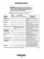
MAINTENANCE SCHEDULE
A WARNING: Never attempt to perform any service while the engine is
running. Wear the proper safety equipment such as goggles and gloves, and
use the correct tools for each job. Disconnect the battery terminals when
servicing any of the engine's DC electrical equipment.
NOTE: Many of the following maintenance jobs are simple but others are more
difficult and may require the expert knowledge of a service mechanic.
SCHEDULED
MAINTENANCE
CHECK
EACH
DAY
HOURS OF OPERATION
50
100
250
500
-,
750 1000 1250
EXPLANATION OF SCHEDULED
MAINTENANCE
Fuel/Water Separator
D
D
Engine Oil Level
D
Oil level should indicate between
dipstick.
Coolant level
0
Check at recovery tank; if empty, check at manifold.
Add coolant if needed.
D
Inspect for proper tension (3/8" to 1/2" depression)
and adjust if needed. Check belt edges for wear.
Fue.l Supply
Drive Belts
Diesel No. 2 rating of 45 cetane or higher.
Check for water and dirt in fuel (drain/replace filter
if necessary).
weekly
Visual Inspection of Engine
0
NOTE: Please keep engine surface clean. Dirt
and oil will inhibit the engine's ability to
remain cool.
Fuel Filter/Inlet Filter
Starting Batteries
(and House Batteries)
Engine
qil (ami filteri
0
0
0
0
0
1\~AX.
and LOW on
Check for fuel, oil and water leaks. Inspect wiring
and electrical connections. Keep bolts & nuts tight.
Check for loose belt tension.
Initial change at 50 hrs, then change every 250 hrs.
Every 50 operating hours check electrolyte levels
and make sure connections are very tight. Clean off
excessive corrosion.
0
weekly
0
D
D
0
0
0
Initial engine oil & filter change at 50 hrs., then
change both every 150 hours.
Generator
0
0
0
0
0
0
0
Check that AC connections are clean and secure
with no chafing. See GENERATOR SECTION
for additional information.
Heat Exchanger Zinc Anode
0
0
0
0
0
0
0
Inspect zinc anode, replace if needed, clear the heat
exchanger end of zinc anode debris.
0
0
D
0
0
0
0
0
0
Drain/Clean every 200 hrs or seasonally.
D
0
0
0
Fuel/Water Separator
Exhaust System
Engine Hoses
0
0
0
*WESTERBEKE recommends this service be performed by an authorized mechanic.
Engines & Generators
11
Initial check at 50 hrs., then every 250 hrs. Inspect
for leaks. Check anti-siphon valve operation. Check
the exhaust elbow for carbon and/or corrosion
buildup on inside passages; clean and replace as
necessary. Check that all connections are tight.
Hose should be hard & tight. Replace if soft or
spongy. Check and tighten all hose clamps.
(continued)
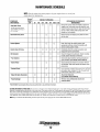
MAINTENANCE SCHEDULE
NOTE: Use the engine hour meter gauge to log your engine hours or record your
engine hours by running time.
SCHEDULED
MAINTENANCE
CHECK
EACH
DAY
HOURS OF OPERATION
50
250
D
EXPLANATION OF SCHEDULED
MAINTENANCE
Remove the pump cover and impeller. Inspect the
impeller, cam, cover and inner wear plate for wear.
Inspect housing weep holes for signs of shaft water
seal or oil leaks. Check shaft bearings (the shaft
should turn, not wobble).
500
750 1000 1250
D
D
Raw Water Pump Drive
D
D
Remove pump and inspect pump shaft and drive
slot for wear.
Coolant System
D
D
Drain, flush, and refill cooling system with
appropriate antifreeze mixture compatible with
various cooling system metals.
Raw Water Pump
100
At 800 operating hours,
disassemble and inspect
for overhaul.
Electric Fuel Lift Pump
D
DC Alternator
D
D
D
D
D
D
*Fuel Injectors
D
Periodically check the wiring connections and
inspect the fuel line connections.
D
Check DC charge from alternator. Check mounting
bracket; tighten electrical connections.
Check and adjust injection opening pressure and
spray condition (see ENGINE ADJUSTMENTS).
D
*Starter Motor
D
D
Check solenoid and motor for corrosion. Remove
and lubricate. Clean and lubricate the starter motor
pinion drive.
*Preheat Circuit
D
D
Check operation of preheat solenoid. Remove and clean
glow plugs; check resistance 0. 9 Ohm. Reinstall with
small amount of anti-seize on threads.
*Adjust the Valve Clearances
D
D
*Heat Exchanger
D
Adjust Valve Clearances
(see ENGINE ADJUSTMENTS).
D
Remove, have professionally cleaned and
pressure tested.
*WESTERBEKE recommends this service be performed by an authorized mechanic.
CAUTION (WESTERLINK or NMEA-2000): The electronic components in the Digital Diesels draw a very small amount of amperage (milli-amps) from the
generators starting battery when the unit is in a static state. This maybe as much as 50.milli-amps for the system ECU and 50 milli-amps for each display.
This can be as much as 72 amp-hours in a months time with no generator use. It is not necessary to be concerned with this slight amperage draw during
normal seasonal use. However, if the generator set is not to be used for a number of months, such as winter storage, it is best to disconnect the DC power
to the generator with a NMEA-2000 system or shut off the DC breaker on the generators control box for a WESTERLINK system.
NOTE: Keep in mind that the Westerbeke generator maybe the DC power supply for the vessel's NMEA-2000 network.
Engines & Generators
12
FUEL SYSTEM·
DIESEL FUEL
Use No.2-D (SAE 1313) diesel fuel with a cetane rating of
#45 or higher. Grade diesel fuel according to ASTM D975.
In conjunction with Ultra Low Sulphur Diesel. Use an
additive such as Diesel Kleen + Cetane Boost produced by
Power Services (product #3025) or equivalent to help
restore fuel lubricity.
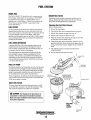
ENGINE FUEL FILTER
FUEL FILTERS
Refer to the illustration.
Periodically check the fuel connections and the bowl for
leakage. Replace the filter element after the first 50 hours
then follow the MAINTENANCE SCHEDULE.
Changing the Fuel Filter Element
1. Shut off the fuel supply.
The fuel injection pump and the fuel injectors are precisely
manufactured and they must receive clean diesel fuel, free
from water and dirt. To ensure this flow of clean fuel, the fuel
must pass through at least two fuel filters, a fuel water
separator and the engine's spin-on fuel filter. Visually inspect,
clean, and change these filters according to the maintenance
schedule in this manual.
2. Tum the fuel filter bowl counterclockwise to remove.
3.. Pull the filter element straight down and off.
4. Inspect both 0-rings and replace if worn.
5. Wipe the 0-rings with clean fuel and snap the new filter
up into place over the small 0-ring.
6. Clean off the filter bowl and threads. (The bowl can be
pre-filled with fuel). Screw the bowl into place when the
0-ring contacts the housing. Tighten the bowl firmly by
hand.
FUEL WATER SEPARATOR
A primary fuel filter of the water separating type must be
installed between the fuel tank and the engine to remove
water and other contaminants from the fuel before they can
be carried to the fuel system on the engine.
7. The preheat sequence will allow the lift pump to
fill the fuel filter.
8. Run the engines and inspect for leaks.
The owner/operator is responsible for making certain the
fuel reaching the engine's injection equipment is free of
impurities. This process is accomplished by installing and
maintaining a proper fuel filter/water separator between the
fuel tank and the generator/engine. Westerbeke recommends
a 10 micron filter be used.
FUEL LIFT PUMP
FROM FUEL
'\ L/FTPUMP
Periodically check the fuel connections to and out of the pump
and make sure that no leakage is present and that the fittings
are tight and secure. The DC ground connection at one of the
pump's mounting bolts should be clean and well secured by
the mounting bolt to ensure proper pump operation.
When energized thru the preheat circuit, the fuel lift pump will
purge air from the fuel system and provide a continuous flow
of fu~l as the engine is running.
SEALING GASKET
APPLY CLEANOIL
...-:::;~$~~ WHEN ASSEMBLING
NEW FILTER
I TO FUEL FILTER
INLET FUEL FILTER
To ensure clean fuel into the fuel lift pump, there is a small
in-line fuel filter connected to the fuel lift pump elbow. This
filter should be replaced every 200 hours of operation.
A WARNING: Fuel leakage at the fuel pump or its
FUEL FILTER
CARTRIDGE
#052985
connections is a fire hazard and should be corrected.
Make sure proper ventilation exists whenever servicing
fuel system components.
j
INCOMING
FUEL
13
·"·
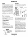
FUEL SYSTEM
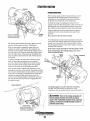
FUEL INJECTION PUMP
BLEED SCREW
The fuel injection pump is the most important component
of the diesel engine, requiring the utmost caution in handling.
The fuel injection pump has been thoroughly bench-tested
and the owner/operator is cautioned not to attempt to service
it. If it requires servicing, remove it and take it to an
authorized fuel injection pump service facility. Do not
attempt to disassembly and repair it.
The bleed screw on the injection pump should be left in the
open position. This will then allow for ease in priming the
engine's fuel system and during engine operation allow for
air in the system to be delivered to the fuel tank through the
fuel return system.
TO FUEL INJECTORS
FROM FUEL
FILTER
ACTUATOR
A
WARNING: Shut off the fuel valve at the tank
when servicing the fuel system. Take care in catching
any fuel that may spill. DO NOT allow any smoking,
open flames or other sources of fire near the fuel
system when servicing. Ensure proper ventilation exists
when servicing the fuel system.
FROM FUEL FILTER
SPEED ADJUSTMENT
FACTORY SET
FUEL INJECTION
PUMP
FUEL RETURN
LlNE ..----- '-- •
GLOW PLUGS
J
A WARNING: Fuel is present in the hosing and lines.
Use extreme care to prevent spillage
FROM FUEL INJECTION PUMP
14
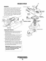
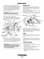
COOLING SYSTEM
DESCRIPTION
Heat Exchanger
Westerbeke marine diesel engines are designed and equipped
for fresh water cooling. Heat produced in the engine by combustion and friction is transferred to fresh water coolant
which circulates throughout the engine. This circulating fresh
water coolant cools the engine block, its internal moving
parts, and the engine oil. The heat is transferred externally
from the fresh water coolant to raw water by means of a heat
exchanger, similar in function to an automotive radiator. Raw
water flows through the tubes of the heat exchanger while
fresh water coolant flows around the tubes; engine heat transferred to the fresh water coolant is conducted through the
tube walls to the raw water which is then pumped into the
exhaust system where finally it is discharged overboard. In
other words, the engine is cooled by fresh water coolant, this
coolant is cooled by raw water, and the raw water carries the
transferred heat overboard through the exhaust system. The
fresh water coolant and raw water circuits are independent of
each other. Using only fresh water coolant within the engine
allows the cooling water passages to stay clean and free from
harmful deposits.
The heat exchanger is a copper tube which encloses a
number of small copper tubes. Raw water is pumped through
the small copper tubes and the freshwater coolant from the
engine is circulated around the copper tubes. The raw water
removes heat from the freshwater coolant.
HEAT EXCHANGER ,
#052493
HEAT EXCHANGERS ARE
ALOO AVAILABLE WITH
CUPRO-N/CKEL TUBING
\
.L
COVER
#022850
RAW WATER INTAKE STRAINER
NOTE: Always install the strainer at or below the waterline so
the strainer will always be self-priming.
Zinc Anode
A clean raw water intake strainer is a vital component of the
engine's cooling system. Include a visual inspection of this
strainer when making your periodic engine check. The water
in the glass should be clear.
Perform the following maintenance after every 100 hours of
operation:
1.
2.
3.
4.
5.
6.
••
BAD
BAD
CLEAN
· AND
REUSE
A zinc anode, or pencil, is located in the raw water cooling
circuit within the heat exchanger. The purpose of the zinc
anode is to sacrifice itself to electrolysis action taking place
in the raw water cooling circuit, thereby reducing the effects
of electrolysis on other components of the system. The
condition of the zinc anode should be checked monthly and
the anode cleaned or replaced as required. Spare anodes
should be carried on board.
Close the raw water seacock.
Remove and clean the strainer filter.
Clean the glass.
NOTE: Electrolysis action is the result of each particular
installation and vessel location; not that of the generator.
Replace the washer if necessary.
Reassemble and install the strainer.
If the zinc pencil needs replacement, hold the hex boss into
which the zinc pencil is threaded with a wrench while
loosening the anode with another wrench. This prevents the
hex boss from possibly tearing off the exchanger shell. After
removing the zinc, note the condition of it. If the zinc is in
poor condition, there are probably a lot of zinc flakes within
the exchanger. Remove the end of the heat exchanger and
clean the inside of all zinc debris. Always have a spare heat
exchanger end gasket in case the present one becomes
damaged when removing the end cover. Replace the gasket
(refer to your engine model's heat exchanger end gasket part
number), o-ring, cover, and install a new zinc pencil.
Open the, seacock. ·
7. Run the engine and check for leaks.
NOTE: Also follow the above procedure after having run hard
aground.
If the engine temperature gauge ever shows a higher than
normal reading, the cause may be that silt, leaves or grass
may have been caught up in the strainer, slowing the flow of
raw water through the cooling system.
TYPICAL RAW WATER STRAINER
(OWNER INSTALLED)
Heat Exchanger Service
INCOMING
RAW WATER
After approximately 1000 hours of operation, remove, clean
and pressure test the engine's heat exchanger. (A local
automotive radiator shop should be able to clean and test the
heat exchanger.)
INSPECT AND
CLEAN EVERY
tOO HOURS
SEACOCK
15
COOLING SYSTEM.
THERMOSTAT
A thermostat, located near the manifold at the front of the
engine, controls the coolant temperature as the coolant
continuously flows through the closed cooling circuit.
When the engine is first started, the closed thermostat prevents coolant from flowing (some coolant is by-passed
through a hole in the thermostat to prevent the exhaust
manifold from overheating). As the engine warms up, the
thermostat gradually opens. The thermostat is accessible
and can be checked, cleaned, or replaced easily. Carry a
spare thermostat and gasket.
TWIST THE
THERMOSTAT
ASSEMBLY
GASKET
#298843
APPLY SEALANT
WHEN INSTALLING
LOOSEN THIS HOSE CLAMP
THERMOSTAT HOUSING
1. Drain off some coolant: Release the coolant pressure cap
and drain the coolant to the approximate level off the
thermostat housing. This can be done using the heat
exchanger drain plug.
2. Rotate the thermostat assembly: Loosen the hose clamp
as shown and remove the three allen screws that hold
down the thennostat housing cover, the assembly can now
be twisted enough to access the gasket and thermostat.
3. Remove/replace the gasket and thermostat: When
installing the new parts, apply a thin coat of sealant on
both side of the gasket before pressing it into place.
4. Re-assemble and test: Tum the cover back into place and
tighten the three screws. Do not over-tighten! Tighten the
hose clamp and tighten the drains. Top off the coolant and
run the engine. Check for normal temperature and for any
leaks around the thermostat assembly.
A CAUTION: The engine must be allowed to cool
down before attempting these procedures. Not only
is the surface of the engine hot but coolant
temperatures can be at 190° F.
Engines & Generators
16
COOLING SYSTEM
FRESH WATER COOLING CIRCUIT
CHANGING COOLANT
NOTE: Refer to the ENGINE COOLANT section for the
The engine's coolant must be changed according to the
MAINTENANCE SCHEDULE. If the coolant is allowed to
become contaminated, it can lead to overheating problems.
recommended antifreeze and water mixture to be used as the
fresh water coolant.
Fresh water coolant is pumped through the engine by a circulating pump, absorbing heat from the engine. The coolant
then passes through the thermostat into the manifold, to the
heat exchanger where it is cooled, and returned to the engine
block via the suction side of the circulating pump.When the
engine is started cold, external coolant flow is prevented by
the closed thermostat (although some coolant flow is
bypassed around the thermostat to prevent the exhaust manifold from overheating). As the engine warms up, the thermostat gradually opens, allowing full flow of the engine's
coolant to flow unrestricted to the external portion of the
cooling system.
Coolant Recovery Tank
A coolant recovery tank allows for engine coolant expansion
and contraction during engine operation, without any significant loss of coolant and without introducing air into the cooling system. This tank should be located at or above the
engine manifold level and should be easily accessible.
A CAUTION: Proper cooling system maintenance is
critical; a substantial number of engine failures can be
traced back to cooling system corrosion.
Drain the engine coolant by removing the drain plug on the
engine block and opening the manifold pressure cap. Flush
the system witli fresh water, then reinstall the drain and start
the refill process.
NOTE: The drain petcock on the heat exchanger should also
be used to help drain engine coolant.
A WARNING: Beware of the hot engine coolant.
Wear protective gloves.
KEEP THE
COOLANT PASSAGE
CLEAR
TO COOLANT
RECOVERY TANK
l
COOLANT EXPANSION
FROM COOLANT
RECOVERY TANK
PRESSURE
/CAP
pressure cap. Ensure the upper and lower rubber seals are in
good condition. Check to ensure
the vacuum valve opens and
closes tightly. Carry a spare
cap. Check also to ensure the
coolant passage is clear so
coolant within the system is
able to expand and contract
to and from the coolant recovery tank.
1
~
\(
1
f\
~~
~~~
I
I
·
I
Refilling the Coolant
After closing the engine block drain, pour clean, premixed
coolant into the manifold and when the coolant is visible in
the manifold, start the engine and run it at slow idle. Open
the air bleed petcocks on the manifold and the thermostat
housing.
COOLANT RETRACTION
NOTE: Periodically check the condition of the manifold
COOLANT
RECOVERY
TANK
I
LE~TFRONT
SIDE OF BLOCK
. BELOW THE ALTERNATOR
INSPECT AND CLEAN
THE COOLANT RECOVERY
TANK AND ITS CONNECTING
HOSE EVERY 3 MONTHS
Monitor the coolant in the manifold and add as needed. Fill
the manifold to the filler neck and when the coolant flowing
from the petcock is free of air bubbles, close the petcock and
install the pressure cap.
Remove the cap on the coolant recovery tank and fill with
coolant mix to halfway between LOW and MAX and replace
the cap. Run the engine and observe the c.oolant expansion
flow into the recovery tank. When the petcock on the thermostat housing is free of air bubbles, close that petcock.
After checking for leaks, stop the engine and allow it to cool.
Coolant should draw back into the cooling system as the
engine cools down. Add coolant to the recovery tank if
needed. Clean up any spilled coolant.
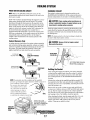
COOLING SYSTEM
RAW WATER COOLING CIRCUIT
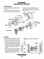
RAW WATER PUMP
#042175
The raw water flow is created by a positive displacement
impeller pump. This pump draws water directly from the
ocean, lake, or river from a thru-hull opening through a hose
to the water strainer. The raw water passes from the strainer
through the pump to the heat exchanger (through the heat
exchanger tubes) where it cools the engine's circulating fresh
water coolant. The raw water is then discharged into the
water-injected exhaust elbow, mixing with, and coolirtg the
exhaust gasses. This mixture of exhaust gas and raw water is
driven through the stem tube and overboard.
IMPELLER-COAT
BLADES WITH
GLYCERINE
Raw Watet Pump
IMPELLER
INSPECTION: CHECK AT THE BASE
EACH BLADE BY BENDING VIGOROUSLY.
REPLACE THE IMPELLER IF THERE
ARE ANY CRACKS.
WHEN INSTALLING: TAKE CARE TO ALIGN
THE IMPELLER KEYWAY WITH THE SHAFT
KEY. FOLD THE IMPELLER BLADES IN
EITHER DIRECTION {THEY WILL TURN IN
THE CORRECT POSITION WHEN THE
IMPELLER STARTS TO ROTATE).
The raw water pump is a self-priming, rotary pump with a
non-ferrous housing and a Neoprene impeller. The impeller
has flexible blades which wipe against a curved cam plate
within the impeller housing, producing the pumping action.
On no account should this pump be run dry. There should
always be a spare impeller and impeller cover gasket aboard
(an impeller kit). Raw water pump impeller failures occur
when lubricant (raw water) is not present during engine
operation. Such failures are not warrantable, and operators
are cautioned to make sure raw water flow is present at
start-up. The raw water pump should be inspected
periodically for broken or tom impeller blades. See
HOUSING
IMPEUERKIT
#200175
MAINTENANCE SCHEDULE.
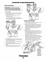
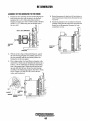
CHANGING THE RAW WATER PUMP IMPELLER
AIR INTAKE/SILENCER
1. Close the raw water intake valve and unfasten the two
hose connection on the inlet and outlet nipples of the
pump.
2. Remove the cap screws and hold down brackets that
secure the pump to the front gear case and lift the pump
off the engine. Check the pump's shaft drive tang for wear
and also the drive in the engine.
The air intake port supplies cooling air to the control panel
electronics. this air flow continues to the engines air
intake/silencer to supply fresh air to the engine.
This system requires NO maintenance.
NOTE: If the unit is being operated
in an area where air born contaminants
(silicon) are present. An external air filter
must be added.
3. Remove the three cap screws that secure the impeller
housing to the pump body (note the position of the
housing to the pump body) and remove the housing .
exposing the sea water impeller.
4. Pull the impeller off the keyed shaft and install the
AIR INTAKE PORT
replacement.
KEEP FREE FROM
5. Lightly coat the inside of the impeller housing with
OBSTRUCTION
glycerine lubricant. Check the condition of the housing
sealing 0-ring. Replace if needed.
6. Replace the impeller housing over the impeller
positioning it correctly on the body and secure it in place
with the three cap screws.
7. Secure the pump onto the gear case aligning the pump's
shaft tang with the drive slot.
8. Reattach the water hoses and open the water intake
valve. Run the unit and check for leaks.
Engines & Generators
18
CONTROL PANEL
AIR INTAKE
SILENCER
ENGINE LUBRICATING OIL
GASKET
APPLY CLEAN OIL
TO SEALING GASKET
ENGINE OIL CHANGE
1. Draining the Oil Sump. Discharge the used oil through
the sump drain hose (attached to the front of the engine)
while the engine is warm. Drain the used oil completely,
replace the hose in its brocket, and replace the end cap
securely.
NOTE: Thread size for the lube oil drain hose capped end
is 114 NPT.
~·.....~'-'~
SPIN-ON
OIL FILTER
CARTRIDGE
#011951
OIL DRAIN
11/16"
SOCKET
FOR EXTENSION
114" NPT
Always observe the used oil as it is removed. A yelh>w/gmy
emulsion indicates the presence of water in the oil. Although
this condition is mre, it does require prompt attention to
prevent serious damage. Call a qualified mechanic should
water be present in the oil. Raw water present in the oil can
be the result of a fault in the exhaust system attached to the
engine and/or a siphoning of raw water through the raw
water cooling circuit into the exhaust, filling the engine. This
problem is often caused by the absence of an anti-siphon
valve, its poor location or lack of maintenance.
NOTE: Generic filters are not recommended, as the
material standards or diameters of important items on
generic parts might be entirely different from genuine
parts. Immediately after an oil filter change and oil fill,
nin the engine to make sure the oil pressure is normal
and that-tl'tr.tre are no oil leaks around the new oil filter.
2. Replacing the Oil Filter. When removing the used oil
filter, you may find it helpful and cleaner to punch a hole
in the upper and lower portion of the old filter to drain
the oil from it into a container before removing it:·This
helps to lessen spillage. A small automotive filter wrench
should be helpful in removing the old oil filter.
NOTE: Do not punch this hole without first loosening the
filter to make certain it can be removed.
3. Filling the Oil Sump. Add new oil through the oil filler
cap on the top of the engine. After refilling, run the
engine for a few moments while checking the oil
pressure. Make sure there is no leakage around the new
oil filter or from the oil drain system, and stop the engine.
Then check the quantity of oil with the lube oil dipstick.
Fill to, but not over the high mark on the dipstick, should
the engine require additional oil.
Place some paper towels and a plastic bag around the
filter when unscrewing it to catch any oil left in the filter.
(Oil or any other fluid on the engine reduces the engine's
cooling ability. Keep your engine clean.) Inspect the old
oil filter as it is removed to make sure that the rubber
sealing gasket comes off with the old oil filter. If this
rubber sealing gasket remains sealed against the filter
brocket, gently remove it.
A WARNING: Used engine oil contains harmful
contaminants. Avoid prolonged skin contact. Clean skin
and nails thoroughly using soap and water. Launder or
discard clothing or rags containing used oil. Discard
used oil properly.
When installing the new oil filter element, wipe the filter
gasket's sealing surface on the bracket free of oil and
apply a thin coat of clean engine oil to the rubber gasket
on the new oil filter. Screw the filter onto the threaded oil
filter nipple on the oil filter bracket, and then tighten the
filter firmly by hand.
NOTE: Change the engine lube oil and filter initially after the
first 50 hours of engine break in. Then change the lube oil
and filter at 150 hour intervals.
19
OIL PRESSURE
DESCRIPTION
The lubricating system is a pressure feeding system using
an oil pump. The engine oil is drawn from the oil sump by
the oil pump, which drives the oil, under pressure, through
the oil filter, oil cooler and various lubricating points in the
engine. The oil then returns to the oil sump to repeat the
continuous cycle. When the oil pressure exceeds the specified pressure, the oil pushes open the relief valve in the oil
pump and returns to the oil sump, keeping the oil pressure
within its specified range.
TESTING OIL PRESSURE
\
NOTE: To test the oil pressure, install a mechanical pressure
gauge as shown. Warm up the engine and read the oil pressure
gauge. Oil Pressure should be 35.0 lb/in' (3.8 Kg/em') or more
o<i801hpm.-
~~
OIL PRESSURE
The engine's oil pressure, during operation, is indicated
by the oil pressure gauge on the instrument panel. During
normal operation, the oil pressure will range between 40 and
60 psi (2.8 and 4.2 kg/cm2).
NOTE: A newly started, cold engine can have an oil pressure
reading up to 60 psi (4.2 kg!cm2 ). A warmed engine can have
an oil pressure reading as low as 35 psi (2.5 kg/cm 2}. These
readings will vary depending upon the temperature of the
engine and the rpms.
LOW OIL PRESSURE
OIL PRESSURE SENSOR
The specified safe minimum oil pressure is 4.3 + 1.4 psi (0.3
+ 0.1 kg/cm2). A gradual loss of oil pressure usually indicates
a worn bearings. For additional information on low oil pressure readings, see the ENGINE TROUBLESHOOTING chart.
An oil pressure sensor is mounted on the oil manifold for the
engine. It sends a voltage signal to the ECU that is interpreted
as pressure. Should this signal fall below a set point in the
ECu. The ECU will open the K2 run relay shutting the unit
down. It will then display the fault on the LCD Display
screen. Engine oil pressure dropping 10- 15 psi will cause
this to occur.
OIL PRESSURE RELIEF VALVE
The oil pressure relief valve is located in the front gear case
cover below the lube oil filter. It is held in place by an Smm
allen head plug. This valve opens at approximately 50 psi
(343kpa) and operates to maintain the pressure in the lube oil
feed system.
NOTE: To test the oil pressure, install a mechanical pressure
gauge as shown. Warm up the engine and read the oil pressure gauge. Oil Pressure should be 35.0 lb/in2 (3.8 Kg/cm 3)
or more at 1800 rpm.
20
REMOTE OIL FILTER (OPTIONAL)
PN.#054372
INSTALLATION
NOTE: Westerbeke is not responsible for engine failure due to
This popular accessory is used to relocate the engine's oil filter from the engine to a more convenient location such as an
engine room bulkhead.
incorrect installation of the Remote Oil Filter.
A CAUTION:
It is vital to install the oil lines correctly. If the oil flows in the reverse direction, the bypass valve in the filter assembly will prevent the oil
from reaching the engine causing an internal engine
failure. If there is no oil pressure reading, shutdown
immediately and check the hose.connreclrton s.
NOTE: Refer to ENGINE OIL CHANGE in this manual for
instructions on removing the oil filter.
To install, simply remove the engine oil filter and thread on
WESTERBEKE's remote oil filter kit as shown. Always
install this kit with the oil filter facing down as illustrated.
Contact your WESTERBEKE dealer for more information.
1
APPLY A THIN COAT OF CLEAN OIL TO THE D-RING WHEN
INSTALLING THIS KIT. THREAD THE KIT ON, THEN HAND
TIGHTEN AN ADDITIONAL 3/4 TURN AFTER THE D-RING
CONTACTS THE BASE.
THE IN CONNECTION HOSE
MUST ATTACH TO THE OUT
CONNECTION AT THE
,"G~...f-----l~~llllnH OIL FILTER.
THE OUT CONNECTION
MUST ATTACH TO THE IN
CONNECTION AT THE
REMOTE OIL FILTER.
APPLY A THIN COAT OF CLEAN OIL TO THE FILTER
GASKET WHEN INSTALLING. AFTER THE FILTER
CONTACTS THE BASE, TIGHTEN IT AN ADDITIONAL
WESTERSEKE
Engines & Generators
21
r---THISWIRENOTREQUIREDFORTHISAPPLICATION
~~ll
-+1.
Ll;m
I
n
JIU
CURR~~~Li!~S[
12 VOLT WIRING DIAGRAM #53731
"\
~~~~ t,}~lH~~H~ ~
>~
•
"a
~
8-f'OS rnMNAL El.OCK
!
®
~
IN I
-
I
I
.I
~
:~
__
~~
,
,
g.~
CQ
N
~-
iii
U)
~~
a
Li
0
Nlloiil'
STATOR~
o-::at
'":
(11 111
-
II~
,,a.Hlllflc~
ORU
SI'EEilliiEMOI
llllllllt[]Ni:
L;;3
I
~c::========-======~
~~
~ (II ,, ~-- ,J
I
"''"""':, •• !1,.
v::-~
~lBI'.s.rot
I
Cl
:1>
EXCITER
_c;;;JI
1
r". __
:,~
:s:
m------
iii
~~~
"'"""'""""~
fORfiRElUPPRESSIOW_
Sl!TlM.lONNECTION
IHE I!OH II
:-··-··-: r-
CONTROL BOX
!AC SIDE)
ROTOR
I
---_I
1--
--
-
0"
-
11
1
-,
+WAY ClllfETllft
~
I
-E:'J
~!"
~-
_,\l
: 111111:
~~
~~
a-
~
118
c.n
;::ii
'10
MllBP. !ENial
II~ JHTI~lll. C~~
1
IHTI5L~
1
'""''''
'""""""
I
~
'";TJ,LK
f
..
-~
-
----------1
~'~1
I
~
""~
ol
~I
-~:
-I
I
·-- OP"Ji:wAL_a:oE_-
CONTROL BOX
RB..AY ADAPTel
IDC SIDE}
IIIENEIGE
R\Nftl 400rM MAX
AI..L.OIA8...E ct.RRfNT.
I
L
=1:1:
-l
1
baoon
I
-
II
II
II
L ____ _
<
!:i
__j
---c-:-:-'--
I
N
=
:e
:-z:a
!I!~ =
=
~
~B
4-
......
~Tl!RY
12WC
~----~
B
-
--
_j
IS NO'
B~
CLOSD
w
......
w
......
,---------
~I
24 VOLT WIRING DIAGRAM #53829
r;;VOlTSEMSE
~
tAIILE
I~
(UAR~:'L~ENSE
NOTE:
I. FIRE SUPRESSION SYSTEN CONNECTION IS NOT
A POWER SOURCE. THIS CIRCUIT MUST B~ CLOSED
TO RUN. OPEN TO STOP GENSEl
t:::::.
I
TERMINAL BLOCK CONNECTIONS
SHOWN fiRE CONFIGURED
FOR 120-240V 60HZ
REFER TO OPERATOR MANUH
....:'""
CS®
~~-
'
24 YDC
FOROTHERACWIRING
.,..,_....,.
U.TT!IIT
~-_1_
L_____J
...______.
0
------.
I
~
M
I
'II
I
"
!"!"~
"'
Ul
VI
,,
WI
N
~
112lH/UO
c<
tiOOR6
~~
AYR
~
- I
~,ifi
~·
i;~-·
CJ
I
II&IHTIYEL
!:i
\._
--:ez
=
-=
:.::-
118WHTI6lK
~
I~
~ :a
[=:J.
1\,)CDO)
~~ i;l ~
'ID
Cl
EXCITBI
:::,
~...,
ID
~
!liS 1:l
I .,_,
:
I
-
Iii I~·..
_.:·l
FOMHi:~;~~!~~l=====:::j::lt:l::'.'_j
! ' !:
CONTROL BOX
!AC SIDE)
.,.....
UlJD
I
I
I
I
-··-··RDTllR
I
_I
II
~
~
~e
I
"8
IHT/Bl~
., .,
...........
--~11'111'
:~';::v~olj_WRi-rrr==:!Ei~=~E~~~~~£=~~~=91•I--SUT~PiE.L•~:w-:
i
~I :;I
I
I
I
I
I
I
:
I.
I
:J : :
CONTROL BOX
tlt_------
'
'
"'LJ;..
.....,....,.,.
<PTU<M.II.OWER
(DC SIDE)
-
-
-
-
-
-
I
000
~~
:1;
T/&lur-::!':=1
JDJ.A.!.AX-iAMPI
.!.II!!.J.!!!! !!!• IMDICATOR
I
L _____ _ -
:s:
--"""'II-,
tiit11
'[i ;
I-
~::::::;=
v---.1
arn.l.SfMI"ISTOf'a.rral
aPCaTD~IIDIBIT.IRY.CIIIII!RJUL
..........
---
AL.L.O'IAEILE CIRIENT.
=1:1::
U'1
;,
ll.,.b'""
I
~. ~--
'··
~
'"'"Tiftl'
w
=
N
CD
c!NA.l::CK C::CTIO:-• I
SHOWN ARE CONFIGUR(D fOR
PAAALL{L·WY£ 1901Z08VAC
==
·~
OPliOKS
WIRING DIAGRAM #529\51 (12 VOLT}
•I
~~~
REHR TO Sll28 FOR OTH[R
u•u
ueu
\
'101.1
NOTES:
CUIJI[II Ull(
c~&\{
II [lt(RUL ALAIN SIST[N COfUI[CTICI IS NOT A POilU $0URC[. CIRCUIT LOGIC IS CLOUD TO RUN l OP[H tO STOP G(IS[T.
ll fOR NMU•lOOO: CQtfN[Cl lAMP ~US£18R[AI[R WIRE TO C2 U.S SHOll • 0C BIUKEI DOU NOT CQITRQl H[tWORK POW£11
roo IISI[ALINRo CONII(CT lAMP IU!EIBRUKEI IIAI TO SI!IDC BRUUR CONIROI.S MITIOAK POWIII
II ICU IILL NOT POI[R UP UNLESS M[TIORK I'OI[R IS PRESENT 01 ICU PI-ll. POW£1 IS SUPPLIED VIA lit[ NEIIORK ClBU TO
IN[ !CU. POI[AIIIG DOIN IN[ NM[A·IDDO N[TIORl INIL[ TH[ GINS[! IS RUINING Will SNUI DOIIt IN[ GENSIT.
X:l::±::-
0
AVR lo!OOEL SRJ
0
c::::J
~=
0
'I U TN[ NMU·lGOO NUWORI IS POJU[D F'ION A SOURC[ [IJUMAL fO TN[ G£1U:T, TV( INT[INAL H[JIORII POWER SUPPLT
I
I
I
(vdiii{i011 tN Hi( PAiti.L 601 I'(USi 8( OISCOHN[Ci(D (1()1 iH£ 4·1AT I[(.
Sl FOR MULTIPLE GINS[IS CONN[CT!D 10 IH[ SAN[ NMIA•IDDD l[TIORl,
BRIAIIR CICLID TO RISTOAE PROPIR NITIORK COMMUNICATIONS.
II 5[£ MITIOR• NARDIAR[ INSTALLATION GUIDI 53011 lOR NOR[ INFORMATION ABilUI NITIOR.. NG.
81 DIGITAl DISPLAY KUSJ IS[ A:CCOMF'IGURCD IN[H CHANGING AJIJ or THE F'OLLOIING SETTINGS
H.! CHANGING ~C fiRING BUI[[II If[ AND OELTA CONFIGURATION
?81 CHANGING AC IIRING UJIE[It 2·11R[ !·PHASE AND l·IIR( I·PMASE
~(I CHANGING BACK[ND B[li[(N I·PNAS[ ARO l·PNAS[.
......
•I
~
II 0111 GENS[! IS SUPPLIIG POIIR TO TME NEliOAI.
lH£ OTHER GENSEl MUSf KAY[ ITS INTUNAl NETWORK POW(R SUPPLf OISCONI[CJ(D F'RON THE 4·1AT T[[.
Dl III[II[V[R NM[A·ZOOG H(TICRK POI[I IS CfCL[D OFF' AIID BACII ON. THE G[l$[1 MU 1[[0 TO 8£ STOPPED AND TN( tK CIRCUIT
I
~I
.
I
rI
I
I
R[D~_IREo
-
._______,
~
"
CIACU!I
U[uU
c:
lXCI TEA
.-··-··-,
~"L'------------,·~~r=J==~--~
r-
LO:!:u
- - - - - -
rEL
I - BATTERY l ( . .
12 IJOC
SWITCH
1
I r~--~---'
sP££o
~
~~
-
~=---++---,
~
-BY
-
OTHERS
-
:e
-
'
-:z
=
-:r:-
:a
I
Cl
:
.~ ..::_
-I
$
[IKAUSI f(llf'. S•UCII
~
"
•
~
N
N
~:it
iill'l'l
:s::
If =
-.....
<
!:i
U1
N
~
~i
~~
=
~
=II:
to
~~
~(lj
IAfU 1[11'. UISOII
~
'IUUT SOUJIOID
A[IIOV[JUIIP[afOII[ItCIHJl~,
,l ••ll
~
~rr~~~~:~~
-
--,
r (.---
I~
<
0..
~(All[
lc>
""
~
18
L
J)
I
GlOI',LUGSII PUClLI
J~
~p:::~=-1a.::1t:====~·__j.-+..__j_
-----
-
0::0
~
[~~:m·:,~.
I Ll•••nJrlll
'
I
D·ll[ll·WJ!f([
N
~
....,....
~
111611
o_II_R_fOI .. IIItiUf~/0.\I.IUl~
-
tTh
~
NETWORK
POWER
T[RMINAl
--,
I
~
~
L
i
"5PJl'EUf8ft'
I
I
Dgl
000
N[I'IQtll POW£1
(ll!(UIT BI[AII(It
!NIT I[ A TUS[ LIISID( Ultl
801
o•
SON£ MOOH U
IUS[
LOfi10Ull
SUIT/STOP SWITCM
IICIIJMTUOI PAN(l60l
[l(CTIOIIICCCIITIOI.JOUPUJUII(L
iOCUU Gil UIU 1101 01 1[1101( LOUTIOI
Q
I.•·••TIIII
IIII{RIUL I[IWOIII
Po.[t SUPPU COIIII[CTOII
S[(IIOI[l
"'""'""'
I
I
~~~~
,-"!''!!'~'!."!'!'~'!'~!!.'!'!!'! -:
I
~
I
~I
Itill
~191
~
IOPTIOIIALI
STAI11STOPSIIIU ·I(IIOI[IIOUIIU
)POSITIOIIMOII(ITU1, CUTUI.O.
:;
v
TU[lPUIIP
~ ·••
1
l
,,_
PGIIIID IilLI IIIII
I
'"'""""'N
OIIDI~'1c':l~ll/. II
:_--------------
~
"I ~
;"I '=~
\_.'
'"'©·
•liEitUTOII
ENGINE TROUBLESHOOTING
LCD DISPLAY FAULTS •
(continued)
Note: The engine's DC electrical system is protected by a 20 amp
rocker type reset circuit breaker mounted on the control panel.
Problem
START BUTION depressed
no panel indicatiins.
START switch depressed
no starter engagement.
Probable Cause
Verification/Remedy
1. Battery Switch not on.
1. Check switch and/or battery connections.
2. Circuit breaker tripped/off.
2. Reset breaker; if breaker trips again, check preheat solenoid circuit and
check circu~ for shorts to ground.
3. Loose battery connections.
3. Check(+) connection to starter solenoid and(-) connection to engine
ground stud. Check battery cable connections.
1. Connection to solenoid faulty.
1. Check connection.
2. Faulty solenoid.
2. Check that 12 volts are present at the solenoid connection.
3. Loose battery connection.
3. Check battery connections.
4.
Low battery.
4. Check battery charge state.
5. K1 Relay
5. Check K1 relay.
START switch is depressed; panel
indications OK; starter solenoid OK
actuator not functioning.
1. Poor connections to actuator.
1. Check connections.
2. Defective actuator.
2. Remove and check actuator.
Generator engine cranks but does not
start, actuator energized.
NOTE: There is an 8-10 sec crank cycle.
If the engine does not start, the cycle
will terminate and a underspeed fault will
display on the LCD display screen.
1. Faulty Fueling system.
1.
1a.
1b.
1c.
1d.
2.
Battery runs down.
1. High resistance leak to ground.
1. Check wiring. Insert sensitive (0- .25 amp) meter in battery lines.
Do not start engine. Remove connections and replace after short is
located.
2. Low resistance leak.
2. Check all wires for temperature rise to locate the fault.
3. Poor battery connections.
3. Check cable connections at battery for loose connections,
corrosion.
4. DC Alternator not charging.
4. Check connections, check belt tension, test alternator.
1. DC charge circuit faulty.
1. Perform DC voltage check of generator charging circuit.
See DC ELECTRICAL SYSTEM/ALTERNATOR in ths manual.
2. Alternator drive.
2. Check drive belt tension. Alternator should turn freely. Check for loose
connections. Check output w~h voltmeter. Ensure 12 volts are present
at the Exe terminal.
1. Switches and/or wiring loose.
1. Inspect wiring for short circu~s and loose connections
Inspect sw~ches for proper operation.
2. Fuel starvation.
2. Check fuel supply, fuel valves, fuel feed strainer.
3. 20 Amp circu~ breaker tripping.
(LCD display blank)
3. Check for High DC amperage draw during operation. Ensure breaker is
not overly sensitive to heat which would cause tripping.
4. Exhaust system is restricted.
4
5. Water in fuel.
5. Pump water from fuel tank(s), change filters and bleed fuel system.
2. Preheat solenoid faulty.
Check that the valves are open.
Sw~ch to combine house and start batteries.
Replace batteries.
Check fuel lift pump.
Change inlet fuel filter.
Chech solenoid.
See DC ELECTRICAL SYSTEM/ALTERNATOR in ths manual.
Battery not charging
Generator engine stops.
(Fault display under speed)
NOTE: There is an 8-10 sec crank cycle. If the
engine does not start, the cycle will terminate
and a underspeed fault will display on the LCD
display screen.
Engine starts, runs, and shuts down.
Exhaust smoking problems
Check for blockage or collapsed muffler.
6. Air intake obstruction.
6. Check air intake filter cartridge.
1. Faulty oil pressure sensor
1. Check oil pressure sensor.
2. Water temperature sensor.
2. Check water temperature sensor.
3. Faulty exhaust temperature switch.
3. Check temperature switch.
1. Blue smoke.
1. Incorrect grade of engine oil.
1a. Crankcase is overfilled with engine oil (oil is blowing out through the
exhaust).
2. White smoke.
2. Engine is running cold.
3. White smoke.
3. Improper grade of fuel or possible generator overload.
2a. Faulty injector or incorrect injector timing.
3a. Fuel burn incomplete due to high back pressure in exhaust or
insufficient air for proper combustion (Check for restrictions in exhaust
system; check air intake.).
3b. Improperly timed injectors or valves or poor compression.
3c. Lack of air- check air intake and air filter. Check for proper ventilation.
Engines & Generators
23
ENGINE TROUBLESHOOTING
LCD DISPLAY FAULTS
PROBLEM
LCD DISPLAY DOES
NOT ILLUMINATE
LOW OIL PRESSURE
HIGH COOLANT TEMPERATURE
PROBABLE CAUSE
VERIFICATION/REMEDY
1. Check battery.
1. Battery on.
2. 20 amp breaker off.
2. Turn breaker on.
3. Loose display connection.
4. 1 amp fuse blown (faulty).
3. Check all cable connections.
4. Check/replace. Determine cause
1. Dillevel low/oil leak.
1. Check oil level, add oil and repair leaks.
2. Lack of oil pressure
2. Test oil pressure. If OK, test oil pressure sendor, inspect
oil filter, inspect oil pump.
3. Ground connection.
3. Check ground connection.
4. Faulty control module (ECU).
4. Inspect all the plug connections/replace.
5. Faulty oil pressure sensor.
5. Check sensor/replace.
1. Add coolant. Check for leaks.
2. Inspect impeller/pump/replace.
3. Adjust belt tension, replace belt.
4. Check sensor/replace.
5. Check ground circuit.
6. Check plug connections/replace.
1. Check system coolant level.
2. Sea water pump.
3. Check water pump drive belt.
4. Faulty temperature sensor.
5. Ground connection.
6. Faulty control module (ECU).
HIGH EXHAUST TEMPERATURE
BATTERY VOLTAGE
GENERATOR FREQUENCY
Overspeed (steady LED)
Underspeed (flashing LED)
1. Check sea water flow.
1. Inspect thru hull fitting, hose and strainer. Correct
as needed.
2. Faulty exhaust temperature switch.
2. TesVreplace.
3. Ground Connection.
3. Check ground circuit.
4. Faulty control module (ECU).
4. Check plug connections.
5. Sea water pump.
5. Inspect impeller/replace.
6. Faulty fire suppression system.
6. By-pass system/check.
1. Check alternator drive belt.
1. Adjust tension/replace if worn.
2. Check charge voltage.
3. Check battery connections.
2. Check excitation. Replace/repair alternator
3. Check + and - cables from battery to engine.
4. Faulty control module (ECU).
4. Check plug connections/replace.
1. Check engine speed.
1. Check speed setting.
2. Inspect filters/replace filters. Test fuel pump operation.
3. Check + and - cables from battery to engine.
4. Check cause for no start.
LED DISPLAY EDGES
TURN PINK
2. Check fuel supply.
3. Amperage load.
4. Crank cycle with no start.
(underspeed fault)
1. Compartment ambient temperature
too high.
WAITING FOR ECU
1. ECU and LCD display not compatible
1. Ventilate compartment.
Note: Heat will often change the color of an LCD
display. This will not effect the operation of the engine.
2. Loose cable connection.
1. Check compatibility with Westerlink or NMEA.
2. Check all cable connections.
3. Panel DC breaker OFF.
3. Turn ON, check DC voltage across breaker.
4. Blown 8 amp fuse.
4. Check/replace fuse. Check DC voltage across fuseholder
5. Terminating Resistors.
5. Check all terminating resistors are in place. 120 ohm
per resister measured across pin #4 and #5.
6. Check between pins P2-24 and P2-25. P2 ECU plug
unplugged from ECU. Power turned ON. If voltage is
present, ECU is faulty.
6. Battery Voltage to ECU.
24
ALTERNATORS TESTING/TROUBLESHOOTING
B
VOLTAGE REGULATOR
#10 ORANGE B
O TO STARTER SOLENOID
50 AMP
DENSO
ALTERNATOR
The integral voltage regulator is an electronic switching
device which senses the system voltage level and switches
the voltage applied to the field in order to maintain a proper
system voltage.
The regulator design utilizes all-silicon semi conductors and
thick-film assembly techniques. After the voltage has been
adjusted to the proper regulating valve, the entire circuit is
encapsulated to protect the circuit and the components from
possible damage due to handling or vibration.
.
REFER TO THE WIRING
DIAGRAM IN THIS
MANUAL FOR ALL
.WIRING CONNECTIONS
ALTERNATOR TROUBLESHOOTING
Use this troubleshooting section to determine if a problem
exists with the charging circuit or with the alternator. If it is
determined that the alternator or voltage regulator is faulty,
have a qualified technician check it.
DESCRIPTION
A WARNING: A working alternator runs hot. A failed
The following information applies to the standard alternators
that are supplied with WESTERBEKE' S Engines and
Generators.
alternator can become very hot. Do not touch the
alternator until if has cooled.
ELECTRICAL CHARGING CIRCUIT
LOW BATTERY/FAULTY CIRCUIT
The charging system consists of an alternator with a voltage
regulator, an engine DC wiring harness, a mounted DC
circuit breaker and a battery with connecting cables. Because
of the use of integrated circuits (IC's), the electronic voltage
regulator is very compact and is mounted internally or on the
back of the alternator.
If the starter only moans or makes a clicking sound instead
of spinning the engine to life it is likely a low battery or a
faulty connection in the starting circuit and not an alternator
problem.
It is desirable to test the charging system (alternator and
voltage regulator) using the wiring harness and electrical
loads that are a permanent part of the system and will then
provide the technician with an operational test of the
charging system as well as the major components of the
electrical system.
Before starting the actual alternator and voltage regulator,
testing the following checks are recommended.
1. Make certain your alternator is securely mounted.
2. Check the drive belts for proper tension. Replace the belt
if it is worn or glazed.
PRELIMINARY INSPECTION
3. Check that all terminals, connectors and plugs are clean
and tight. Loose or corroded connections cause high
resistance and this could cause overcharging,
undercharging or damage to the charging system. Badly
corroded battery cables could prevent the battery from
reaching a fully charged condition.
4. Check the condition of the battery and charge if necessary.
A low or discharged battery may cause false or misleading
readings in the tests.
ALTERNATOR DESCRIPTION
The stator is connected to a three-phase, full-wave bridge
rectifier package which contains six diodes. The bridge
converts the AC generated in the stator to a DC output for
battery charging and accessories,
Power to the regulator and the field of the integral regulator
alternator is provided by the field diode (or diode trio)
package contained in the alternator.
These alternators produce a rated output of 50 or 51 amps.
rated output is achieved at approximately 6000 alternator
rpm at an ambient temperature of 75°F (23.8°C). The
alternators are designed to operate in an ambient temperature
range of -40° to 212°F (-40° to 100°C).
NOTE: An isolator with a diode, a solenoid, or a battery
selector switch is usually mounted in the circuit to isolate
the batteries so the starting battery is not discharged along
with the house batteries. If the isolator is charging the
starting battery but not the house battery, the alternator is
OK and the problem is in the battery charging circuit.
25
ALTERNATORS TESTING/TROUBLESHOOTING
MEASURING
BATTERY VOLTAGE
{IGNITION ON
ENGINE OFF)
TESTING THE ALTERNATOR
A CAUTION: Before starting the engine make
certain that everyone is clear of moving parts! Keep
away from sheaves and belts during test procedures.
1. Start the Engine.
2. After the engine has run for a few minutes, measure the
starting battery voltage at the battery terminals using a
multimeter set on DC volts.
a. If the voltage is increasing toward 14 volts, the
alternator is working.
b. If the voltage remains around 12 volts, a problem
exists with either the alternator or the charging circuit;
continue with Steps 3 through 6.
MEASURING
BATTERY VOLTAGE
(ENGINE RUNNING)
TESTING THE OUTPUT CIRCUIT
EEQJ
1. Connect the positive probe to the output terminal B and
~llfL&t2~,l
connect the negative probe to ground.
2. Wiggle the engine wiring harness while observing the
voltmeter. The meter should indicate the approximate
battery voltage, and should not vary. If no reading is
obtained, or if the reading varies, check the alternator
output circuit for loose or dirty connections or
damaged wiring.
3. Start the engine.
4. Repeat the same measurement, the negative probe to
ground, the positive probe to B with the engine running.
The voltage reading should be between 13.5 and 14.5
volts. If your alternator is over or under-charging, have
it repaired at a reliable service shop.
5. If the previous test reads only battery voltage at
terminal B, use the meter to measure the DC excitation
terminal. If 12 volts is not present at exciter terminal R,
inspect the wiring for breaks and poor connections.
Jump 12 volts from a 12 volt source (such as the
battery) and operate the alternator. If the voltage output
is 13-14 volts, .. then the alternator is OK.
3. Thrn off the engine. Inspect all wiring and connections.
Ensure that the battery terminals and the engine ground
connections are tight and clean
4. If a battery selector switch is in the charging circuit,ensure
that it is on the correct setting.
5. Thrn on the ignition switch, but do not start the
engine.
6. Check the battery voltage. If your battery is in good
condition the reading should be 12 to 13 volts.
\
TESTING THE OUTPUT
CIRCUIT ENGINE RUNNING
(+)
26
ALTERNATORS TESTING/TROUBLESHOOTING
TESTING THE EXCITATION CIRCUIT
CHECKING THE SERVICE BAnERY
1. Connect the positive(+) multimeter probe to the
Check the voltage of the service battery. this battery should
have a voltage between 13 and 14 volts when the engine is
running. If not, there is a problem in the service battery
charging circuit. Troubleshoot the service battery charging
circuit by checking the wiring and connections, the solenoid,
isolator, battery switch, and the battery itself.
When the problem has been solved and before the alternator
is back in operation, take the time to tighten and clean the
terminal studs. Also clean the connecting terminals from the
wiring harness.
excitation terminal R on the alternator and the negative
(-) lead to ground.
2. Thrn the ignition switch to the on position and note
the multimeter reading. The reading should be 1.3 to
2.5 volts (see illustration).
TESTING THE
EXCITATION
CIRCUIT
(ENGINE
RUNNING)
ALTERNATOR REPAIR
If tests indicate a failed alternator, it will need to be disassembled and repaired. Any good alternator service shop can
do the job.
NOTE: WESTERBEKE'S Service Manual has detailed
instructions for the disassembly and repair of their
standard alternators.
BAnERYCARE
The minimum recommended capacity of the battery used in
the engine's 12 volt DC control circuit is 600- 900 Cold
Cranking Amps (CCA).
Review the manufacturer's recommendations and then
establish a systematic maintenance schedule for your
engine's starting batteries and house batteries.
3. If the reading is between .75 and 1.1 volts, the
rotor field circuit probably is shorted or grounded.
4. If the reading is between 6.0 and 7.0 volts, the rotor
field circuit probably is open.
5. If no reading is obtained, an open exists in the
alternator-excitation lead or in the excitation circuit of
the regulator. Disconnect the lead from exc terminal R.
Connect the positive multimeter probe to the excitation
lead and the negative multimeter probe to ground.
If the multimeter now indicates an approximate battery
voltage, the voltage regulator is defective and must be
replaced. If no voltage is indicated, check the
excitation circuit for loose or dirty connections or
damaged wiring.
•
Monitor your voltmeter for proper charging during
engine operation.
•
Check the electrolyte level and specific gravity with a
hydrometer.
•
U,se only distilled water to bring electrolytes to a proper
level.
•
Make certain that battery cable connections are clean and
tight to the battery posts (and to your engine).
A
CAUTION: To avoid damage to the battery charging
circuit, never shut off the engine battery switch while
the engine is running. Shut off the engine battery switch,
however. to avoid electrical shorts when working on the
engine's electrical circuit.
EXCITER
TERMINAL
TESTING THE
EXCITATION
CIRCUIT
ENGINE
RUNNING
27
ENGINE ADJUSTMENTS
NOTE: WESTERBEKE recommends that the following engine adjustments be performed by a competent engine mechanic. The information
below is provided to assist the mechanic.
CHECKING VALVE CLEARANCE
Valve clearance must be checked and adjusted when engine
is cold.
1. Remove the head cover.
2. Align the lTC mark line on the flywheel and projection
on the housing so that the No. I piston comes to the
compression or overlap top dead center.
3. Check the following valve clearance (1) marked with
using a feeler gauge.
4. If the clearance is not within the factory specification,
adjust with the adjusting screw.
VALVE CLEARANCE 0.18 • 0.22mm (0.0071 - 0.0087 in)
The TC marking line on the flywheel is just for the No. 1
There is no TC marking for the other cylinders. The No.1
piston comes to the top dead center position when the TC
marking is aligned with the projection in the window on
the flywheel-housing. Turn the flywheel 0.26 radius (15°)
clockwise and counterclockwise to see if the piston is at
the compression top dead center or the overlap position.
Now, referring to the table below, readjust the valve
clearance. The piston is at the top dead center when both
the IN. and EX. valves do not move. It is at the overlap
position when both the valves move.
Finally, turn the flywheel 6.28 radius (360°) and align the
TC marking and the projection perfectly. Adjust all the other
valve clearances as required.
After turning the flywheel counterclockwise twice or three
times, recheck the valve clearance.
After adjusting the valve clearance, firmly tighten the locknut
of the adjusting screw.
TIMING WINDOW
""
IN.
EX.
IN.
EX.
No.1
When No. 1 piston is
No.2
compression top dead
No.3
center
No.4
*
*
*
*
*
*
*
*
*
*
*
*
-
4 CYL.
-
No.1
When No. 1 piston is
overlap position
No.2
No.3
*
No.4
-
-*
\I
lTC MARK
Valve arrangement
3 CYL.
FLYWHEEL
~
*
Adjustable
cylinder
location of piston
l\
PROJECTION
28
J
I
FLYWHEEL
HOUSING
ENGINE ADJUSTMENTS
DRIVE BELT ADJUSTMENT
GLOW PLUG
CONNECTION STRAP
Proper inspection, service and maintenance of the drive belts
is important for the efficient operation of your engine (see
Drive Belts under MAINTENANCE SCHEDULE).
Drive belts must be properly tensioned. Loose d1ive belts
will not provide proper alternator charging and will
eventually damage the alternator. Drive belts that are too
tight will pull the alternator out of alignment and/or cause
the alternator to wear out prematurely. Excessive drive belt
tension can also cause rapid wear of the belt and reduce the
service life of the coolant pump's bearing. A slack belt or the
presence of oil on the belt can cause belt slipping, resulting
in high operating temperatures and tachometer variations.
GLOW PLUGS
The drive belt is properly adjusted if the belt can be deflected
no less than 3/8 inch (lOmm) and no more than 1/2 inch
(12mm) as the belt is depressed with the thumb at the midpoint between the two pulleys on the longest span of the belt.
A spare belt or belts should always be canied on board.
A
WARNING: These glow plugs will become very hot
·to the touch. Be careful not to burn your fingers when
testing plugs.
A WARNING: Never attempt to check or adjust the
To inspect the plug, remove the electrical terminal connections,
then unscrew or unclamp each plug from the cylinder head.
Thoroughly clean each plug's tip and threads with a soft brush
and cleaning solution to remove all the carbon and oil deposits.
While cleaning, examine the tip for wear and bum erosion; if it
has eroded too much, replace the plug.
drive belt's tension while the engine is in operation.
Adjusting Belt Tension
1. Loosen the alternator adjusting strap bolt and the base
mounting bolt.
2. With the belt loose, inspect for wear, cracks and frayt>-d.
An accurate way to test glow plugs is with an ohmmeter.
Touch one prod to the glow plug's wire connection, and the
other to the body of the glow plug, as shown. A good glow
plug will have a 0.90 ohm resistance. This method can be used
with the plug in or out of the engine. You can also use an
ammeter to test the power drain (12-13 amps per plug)
edges.
3. Pivot the alternator on the base mounting bolt to the left
or right as required, to loosen or tighten.
4. Tighten the base mounting bolt and the adjusting strap
bolt.
5. Run the engine for about 5 minutes, then shut down and
recheck the belt tensions.
Re-install the plugs in the engine and test them again. The
plugs should get very hot (at the terminal end) within 7 to 15
seconds. If the plugs don't heat up quickly, check for a short
circuit. When reinstalling the glow plugs, use anti-seize
compound on the threads.
ADJUSTING STRAP
BOLT
WIRE CONNECTION~
-
ALTERNATOR
GLOWPLUG
BODY
TIGHTENING TORQUE
2.0-2.5 m-kg (14.5 -18.0 tt-lb)
In case of severe vibrations and detonation noise, have the
injectors checked and overhauled by an authorized fuel
injection service center. Poor fuel quality, contaminant's and
loss of positive fuel pressure to the injection pump can result
in injector faults. Since fuel injectors must be serviced in a
clean room environment, it is best to carry at least one extra
injector as a spare should a problem occur. Refer to the
following page for injector testing.
29
FUEL INJECTORS
REMOVING THE INJECTORS
Inspecting Spray Pattern
NOTE: Injector must be serviced in a "clean room" emirmunent.
1. Operate the hand lever of the nozzle tester at intervals of
one stroke per second to check if the fuel is injected correctly in its axial direction. A nozzle is defective if it
injects fuel in an oblique direction or in several separate
strips. Also, a spray in the fonn of particles indicates a
defect. These defects may sometimes be caused by clogging with dust and, therefore, ali pmts should be cm·efully
cleaned before reassembly. (Care should be taken not to
expose ones skin to this spray as it may penetrate the skin
and cause infection.)
1. Disconnect the high pressure lines from the injectors and
loosen the lines at their attachment to the injection pump
and move them out of the way of the injectors. Avoid
bending the lines.
2. Using a 17mm long socket, remove the fuel return line in
its entirety from the top of the injectors. Take care not to
lose the two sealing washers and banjo bolt that attaches
the fuel return line to each injector.
3.
The injector seats in the cylinder head on a copper sealing washer. This washer should be removed with the
injector and replaced with a new washer when the injector is reinstalled.
~1,r 1 NORMAL
j 11r
•/rill
lrriJ 1
:J!l;\
Ill;:•
"
!;, ,FAULTY
FAULTY
'
¥~~
.-~~
\.
II
,,,
~I
...
I"
CHATTERING TEST
hOI
A CAUTION: The spray injected from the nozzle is
DRIP TEST
The injection starting pressure for the injectors is adjusted by
increasing or decreasing the tlllckness of the adjusting shim.
TI1e shim has I 0 different tlllcknesses for every 0.0020 in
(0.05 rnrn)~ between 0.0049in (1.25mm).to 0.0669in (1.7mm)
With each 0.0020in (0.05mm) increase, injection pressure is
increased approximately 7l.llb/in2 (5.0 kg/cm2). \Vhen
replacing tl1e shim, grip the retaining nut in a vise and
remove ti1e body with a wrench. Tighten ti1e retaining nut to
the specified torque;
INJECTOR TO CYLINDER HEAD TIGHTENING TORQUE
36.2- 50.6 (49 - 68.6 Nm)
ADJUSTING
SHIM
START TO INJECTION PRESSURE
1991 -2134 psi (13.73 -14.71 MPa)
!
TYPICAL INJECTOR
INJECTOR
. I
~~~
by operating the hand lever, and check the drips from the
nozzle tip. If it drips or has a large accumulation of fuel
on the bottom, it is considered defective and should be
repl!lced. A very small amount of fuel may sometimes
remain on the tip of the nozzle; however, tins does not
indicate a defect.
1. Using the nozzle tester, check the spray pattern and injection starting preSsure of nozzle and, if it exceeds the
linlit, adjust or replace the nozzle. \Vhen using nozzle
tester, take the following precautions:
a. If the diesel fuel of the nozzle tester is discolored,
replace it. At the same time, clean or replace the filter.
b. Set the nozzle tester in a clean place where there is no
dust or dirt.
c. Mount the nozzle and nozzle holder on the nozzle
tester.
d. Use tl1e fuel at the approximate temperature
of 68° F (20° C)
e. Operate the hand lever of nozzle tester several times to
bleed the air in the nozzle line, then move the hand
lever at intervals of one stroke per second while reading the injection starting pressure.
ll
~
2. Apply the pressure of 1635lb/in2 (115 kg/cm 2) to nozzle
INJECTION TESTING
of such velocity that it may penetrate deeply into the
skin of fingers and hands, destroying tissue. If it
enters the bloodstream, it may cause blood poisoning.
~
~ td
NOTE: Clean the area around the base of the injector
prior to lifting it out of the cylinder head to help prevent
any rust or debris from falling down into the injector
hole. If the injector will not lift out easily and is held in
by carbon build up or the like, work the injector side to
side with the aid of the I 7mm deep socket wrench to free
it and then lift it out.
Engines & Generators
30
SHIM THICKNESS
PRESSURE VARIATION
WITH 0.01 mm (0.004 in)
ADJUSTING WASHER IS
34 PSI (235 KPa)
STARTER MOTOR
TROUBLESHOOTING
Prior to testing, make certain the ships batteries are at full
charge and that the starting system wiring connections
(terminals) are clean and tight. Pay particular attention to
the ground wire connections on the engine block.
To check the wiring, try cranking the starter for a few
seconds, never more than 10 seconds at a time, then run your
hand along the wires and terminals looking for warm spots
that indicate resistance. Repair or replace any trouble spots.
Using a multimeter, test the voltage between the positive
terminal stud on the start solenoid and the engine block
(ground).
If you read 12 volts, the starter is faulty.
REFER TO THR WIRING
DIAGRAM IN THIS MANUAL
FOR WIRE CONECTIONS
To test the ignition circuit, locate the ignition(s) terminal (it
is one of the small terminal studs and is wired to the ignition
circuit). Use a screwdriver, don't touch the blade, to jump
from that ignition terminal to the positive battery connection
terminal on the solenoid.
If the starter cranks, the fault lies with the ignition circuit.
If the solenoid clicks but nothing happens, the starter
motor is probably faulty.
The starting system includes the battery, starter motor and
solenoid, and the ignition switches - Start/Preheat.
When the start button is depressed, current flows and
energizes the starter's solenoid coil. The energized coil
becomes an electromagnet, which pulls the plunger into the
coil, and closes a set of contacts which allow high current to
reach the starter motor. At the same time, the plunger also
serves to push that starter pinion to mesh with the teeth on
the flywheel.
To prevent damage to the starter motor when the engine
starts, the pinion gear incorporates an over-running
(one-way) clutch which is splined to the starter armature
shaft. The rotation of the running engine may speed the
rotation of the pinion but not the starter motor itself.
POSITIVE (+)
TERMINAL
Once the start switch is released, the current flow ceases,
stopping the activation of the solenoid. The plunger is pulled
out of contact with the battery-to-start cables by a coil spring
and the flow of electricity is interrupted to the starter. This
weakens the magnetic fields and the starter ceases its
rotation. As the solenoid plunger is released, its movement
also pulls the starter drive gear from its engagement with
the engine flywheel.
EXHAUST MANIFOLD
If nothing happens at all, the solenoid is not getting
current.. Check the battery and inspect the wiring
connections. It is also possible that the solenoid is defective.
A WARNING: There will be arching and sparks will
fly when jumping terminals. Be certain the engine
space is free of potentially explosive fumes, especially
gasoline, and that there are NO flammable solvents or
materials stored nearby.
GROUND WIRES
REFER TO THE WIRING
DIAGRAM IN THIS MANUAL
FOR WIRING CONNECTIONS
Engines & Generators
31
STARTER MOTOR
Test again by jumping the positive terminal to the M
terminal. Pull back the covering on the M terminal to expose
the connection. Attach a jumper cable to the positive(+)
terminal. Use a battery type cable #8 or better. Tap theM
terminal with the opposite end to see the results. Do not
allow the jumper cable end to touch the solenoid or starter
casing. This would cause a short.
EMERGENCY START
Con·osion to the stmter brushes and/or the solenoid contacts
can cause the sporadic problem of the engine starting one
time but not another. If corrosion is the problem, the starter
will need to be rebuilt.
It is however, sometimes possible to get started by taping the
starter lightly with a small hammer.
With the battery switch off and no ignition, tap lightly on the
starter/solenoid casing as shown, then try to start the engine.
A WARNING: There will be arching as the full
fiY
starting current should be flowing thru the jumper
EXHAUST MANIFOLD
If the starter spins, the solenoid is faulty.
If the starter fails to spin, the motor is probably faulty.
If no arching occurred, there is no juice reaching the
solenoid.
~,,,
.,
,,,,,
,,,
#'''
1, /
,~.A
If that fails, turn the battery switch on and have a crew
member tum the ignition on and off rapidly as you tap again
with the hammer., This may loosen the brushes and allow
contact to start the engine. When you reach a repair facility,
the starter will need to be repaired.
SERVICE
WESTERBEKE uses a standard starter motor which can be
serviced or rebuilt at any starter motor automotive service
center.
REFER TO THR WIRING
DIAGRAM IN THIS MANUAL
FOR WIRE CONECTIONS
NOTE: Starter motors are either inertia type or pre-engaged.
In the pre-engaged model, the solenoid also moves an arm
that engages the starter motor to the flywheel of the engine.
using a screwdriver to bypass the solenoid on such a starter
will run the motor without engaging the flywheel.
If replacing the starter motor, make certain the new motor is
certified for marine use. Automotive starters do not meet
USCG standards. If in doubt, contact your WESTERBEKE
dealer.
TO REMOVE FOR SERVICE
1. Disconnect the negative battery cable.
A WARNING: When performing these procedures,
2. If necessary, remove any components to gain full access
to the starter motor.
position yourself safely away from the moving parts of
the engine in case the engine starts-up. Also warn
other crew members of the danger.
3. Label and disconnect the wiring from the starter. (Do not
allow wires to touch, tape over the terminals).
4. Remove the starter mounting bolts.
5. Remove the starter from the engine. In some cases the
starter will have to be turned to a different angle to clear
obstructions,
32
SPECIFICATIONS 22.0/17.0 EDE
ENGINE SPECIFICATIONS
COOLING SYSTEM
Engine Type
Diesel, four-cycle, four-cylinder, fresh
water-cooled, vertical in-line overhead valve
mechanism (35.5 hp at 1800 rpm maximum)
Aspiration
Naturally aspirated
Compression Ratio
22.6:1
Governor
Electronic
Combustion Chamber
Swirl type
Bore & Stroke
87 x 92.4 mms (3.43 x 3.64 iinches)
Piston Displacement
2.19 liters (134.07 cubic inches)
Firing Order
1-3-4-2
Inclination
Continuous 20°
Temporary 30° (not to exceed 10 min.)
Weight (dry)
829 lbs (376.0 kgs)
Fresh water-cooled engine block,
thermostatically-controlled with heat exchanger.
Operating Temperature
160-180° F(71 -82° C)
Fresh Water Pump
Centrifugal type, metal impeller, belt-driven
Raw Water Pump
Positive displacement, rubber impeller,
gear-driven.
System Capacity
(fresh water)
6 qts (5.61iters)
Raw Water Flow Rate
(at 1800 rpm)
6.0 gpm (22.7 lpm)
FUEL SYSTEM
TUNE-UP SPECIFICATIONS
Compression Pressure
(allowable limit)
General
626 psi (44 kgf/cm') at 250 rpm
472 psi (30.5 kgf/cm') at 250 rpm
General
Open flow, self bleeding, self priming
(electromagnetic fuel pump)
Fuel
No.2 diesel (cetane rating of 45 or higher)
Fuel Injection Pump
Bosch type mini-pump
Fuel Injection Timing
18° BTDC
Injector Nozzle
Bosch throttle type
Spin-on type
Variation between
cylinders
10% or less
Fuel Filter
Injection Timing
18° BTDC
Air Intake
Metal screen/intake silencer box
Engine Speed
1800 rpm 60 Hertz
1500 rpm 50 Hertz
Air Flow Combustion
70.0 ocfm (1.9 cmm)
GENERATOR COOLING
0.18-0.22 mm
(0.0071 - 0.0087 inches)
Valve Clearance
(engine cold)
Injector Pressure
1991 to 2134 psi (140 to 150 kgf/cm')
Valve Timing
Intake Opens 14° BTDC
Intake Closes 36° ABDC
Air Requirements
(generator cooling)
NOTE: Increase cooling air flow 15% for slower turning 50hz units.
AC GENERATOR
Exhaust Opens 45° BBDC
Exhaust Closes 17" ATDC
General - Single Phase
Brushless, four pole revolving field, sealed
lubricated single bearing design. 6 wire
reconnectable with solid state voltage regulator.
Voltage - Single Phase
120 or 120/240 volts 60 Hz
115/230 volts 50 Hz
Voltage Regulation
+ or - 2% no load to full rated amperage outlet
Frequency Regulation
+or- .3hz (.5%) no load to full rated amperage
outlet
Generator Compartment
Ambient Temperature
Recommendations
122° F(50° C) maximum
ELECTRICAL SYSTEM
Starting Battery
12-Volt DC(-) negative ground
Battery Capacity
800-1000 CCA
DC Charging Alternator
40 Amp rated, belt-driven
Starter
1.4Kw, 12VDC direct drive
Starting Aid
Glow plugs, sheathed type
DC Cranking Current
170 -180 Amps
LUBRICATION SYSTEM
General
Pressure fed system with external relief valve
Oil Filter
Full flow, paper element, spin-on type
Sump Capacity
(includes oil filter)
8.0 U.S. qts (7.5 liters)
Operating Oil Pressure
(engine hot)
28 - 57 psi (2.0 - 4.0 kg/em')
Oil Grade
0.8 Power factor unit. 500 CFM (15.0 CMM)
NOTE: Forced ventilation should be provided to
maintain gererator compartment temperature
below 12Z' F (50°C).
KEEL COOLING
API Specification CF, CG-4, CF-4, CH-4, CI-4
SAE IOW-40 or 15W-40
Coolant Flow
Fresh Water Pump
16 gal/min (60.51itres)@ 1800 rpm
Exhaust Connection
2 y, NPT Female
Coolant Hose Size
1 1/4 I.D. (31.75 mm)
Heat Rejection
76,000 BTU/Hr
19,000 KcaVHr
Engines & Generators
33
SPECIFICATIONS 17.0/13.5 EDE
ENGINE SPECIFICATIONS
LUBRICATION SYSTEM
Engine Type
Diesel, four-cycle, three-cylinder, fresh
water-cooled, vertical in-line overhead valve
mechanism.
Aspiration
Naturally aspirated
Compression Ratio
23.8:1
Governor
Electronic
Combustion Chamber
Spherical type
Operating Oil Pressure
(engine hot)
Oil Grade
28 - 57 psi (2.0 - 4.0 kg/em')
API Specification CF, CG-4, CF-4, CH-4, CI-4
SAE IOW-40 or ISW-40
COOLING SYSTEM
General
Fresh water-cooled engine block,
thermostatically-controlled with heat
exchanger.
Bore & Stroke
87 x 92.4 mm (3.43 x 3.64 inches)
Piston Displacement
2.191iters (134.07 cubic inches)
Operating Temperature
160-180° F (71 -82° C)
Fuel Consumption at
rated amperage outlet
1.50 gph (5.7 lph) at 1800 pm
1.22 gph (4.6 lph) at 1500 rpm
Fresh Water Pump
Centrifugal type, metal impeller, belt-driven
Raw Water Pump
HP @ 1800/1500 RPM
38.0/25.6
Positive displacement, rubber impeller,
gear-driven.
Engine Combustion Air
Requirements
1800 rpm 58 cfm (1.64 cmm)
1500 rpm 48 cfm (1.36 cmm)
System Capacity
(fresh water)
5 qts (4.7 liters)
Firing Order
1 -2- 3
Raw Water Flow Rate
(at 1800 rpm)
6.0 gpm (22.7 lpm)
Inclination
Continuous 20°
Temporary 30° (not to exceed 10 min.)
Weight (dry)
829 lbs (376.0 kgs)
FUEL SYSTEM
TUNE-UP SPECIFICATIONS
General
Open flow, self bleeding, self priming
(electromagnetic fuel pump)
Fuel
No.2 diesel (cetane rating of 45 or higher)
Fuel Injection Pump
Bosch type mini-pump
Compression Pressure
(allowable limit)
512- 583 psi (36- 41 kgf/cm') at 250 rpm
370 psi (26 kgf/cm') at 250 rpm
Variation between
cylinders
10% or less
Injector Nozzle
Bosch throttle type
Injection liming
18° BTDC
Fuel Filter
Spin-on type
Engine Speed
1800 rpm 60 Hertz
1500 rpm 50 Hertz
Air Intake
Metal screen/intake silencer box
Valve Clearance
(engine cold)
0.18-0.22 mm
(0.0071- 0.0087 inches)
Air Flow Combustion
70.0 cfm (1.9 cmm)
Injector Pressure
1991 to 2134 psi (140 to 150 kgf/cm')
Fuel Injection liming
Valve liming
GENERATOR COOLING
Air Requirement~
(generator cooling)
Intake Opens 14° BTDC
Intake Closes 36° ABDC
Generator Compartment
Ambient Temperature
ELECTRICAL SYSTEM
12-Volt DC(-) negative ground
Battery Capacity
800-1 000 CCA
DC Charging Alternator
40 Amp rated, belt-driven
Starter
2.0 Kw, 12VDC direct drive
Starting Aid
Glow plugs, sheathed type
DC Cranking Current
240 (includes glow plugs)
250- 275 cfm (7.08- 7.8 cmm)
NOTE: Increase cooling air flow 15% for slower turning 50hz units.
Exhaust Opens 45° BBDC
Exhaust Closes 17° ATDC
Starting Battery
18° BTDC
122° F(50° C) maximum
AC GENERATOR (Single Phase)
LUBRICATION SYSTEM
General
Pressure fed system with external relief
valve
Oil Filter
Full flow, paper element, spin-on type
Sump Capacity
(includes oil filter)
6.3 U.S. qts (6.0 liters)
General-Single phase
Brushless, four-pole, revolving field. Sealed
lubricated, single-bearing design. 6 wire
reconnectable with solid state voltage regulator.
Voltage - Single Phase
120 or 120/240 volts 60 Hz
230 volts 50 Hz
Voltage Regulation
± 2% no load to full load.
Frequency Regulation
±) Hertz (.5%) no load to full rated
amperage outlet
AC Amperage
120 volts/141.7 amps
240 volts70.8 amps
230 volts/58.7 amps
Generator Compartment
Ambient temperature
Recommendations
122° F(50° C) maximum
Engines & Generators
33a
Note- Forced ventilation should be provided to
maintain generator compartment temperature
below 122° F(50° C)
GENERATOR SPECIFICATION 3 PHASE
17.0/13.5 EDE
22.0/17.0 EDE
AC GENERATOR (3 Phase)
AC GENERATOR (3 Phase)
Three Phase
17.0 Kw- 60 Hertz
13.5 Kw - 50 Hertz
Brushless, six- pole, revolving field. Sealed
lubricated, single-bearing design. 12 Lead
reconnectable for low voltage WYE, high
voltage Delta. Solid state voltage regulator with
protection circuitry.
Three Phase
22.0 Kw - 60 Hertz
17.0 Kw- 50 Hertz
Brushless, six- pole, revolving field. Sealed
lubricated, single-bearing design. 12 Lead
reconnectable for low voltage WYE, high
voltage Delta. Solid state voltage regulator with
protection circuitry.
Voltage - 3 phase
(60 Hertz)
Low Voltage WYE
High Voltage WYE
DELTA
240 Volts
480 Volts
240 Volts
Voltage - 3 phase
(60 Hertz)
Low Voltage WYE
High Voltage WYE
DELTA
240 Volts
480 Volts
240 Volts
Voltage - 3 Phase
(50 Hertz)
High Voltage WYE
DELTA
400 Volts
230 Volts
Voltage - 3 Phase
(50 Hertz)
High Voltage WYE
DELTA
400 Volts
230 Volts
Amperage - 3 phase
(60 Hertz)
Low Voltage WYE
High Voltage WYE
DELTA
51 Amps
25Amps
51 Amps
Amperage - 3 phase
(60 Hertz)
Low Voltage WYE
High Voltage WYE
DELTA
66 Amps
33 Amps
66Amps
Amperage - 3 phase
(50 Hertz)
High Voltage WYE
DELTA
24Amps
42Amps
Amperage - 3 phase
(50 Hertz)
High Voltage WYE
DELTA
30Amps
53 Amps
Generator Compartment
Ambient Temperature
Recommendations
122°F (50°C) maximum
Generator Compartment
Ambient Temperature
Recommendations
122°F (50°C) maximum
Air Requirement
Generator Cooling
NOTE: Forced ventilation should be provided
to maintain generator compartment
temperatures below 122°F (50°C).
Air Requirement
Generator Cooling
250-275 cfm
(7.08- 7.8 cmm)
NOTE: Forced ventilation should be provided
to maintain generator compartment
temperatures below 122•F (50°C).
250-300 cfm
(7.08- 8.5 cmm)
NOTE: Increase air flow by 15% for slower
turning 50 Hz units.
NOTE: Increase air flow by 15% for slower
turning 50 Hz units.
Engines & Generators
33b
GENERATOR INFORMATION
USE OF ELECTRIC MOTORS
Generator Maintenance
The power required to start an electric motor is considerably
more than is required to keep it running after it is started.
Some motors require much more current to start them than
others. Split-phase (AC) motors require more current to start,
under similar circumstances, than other types. They are commonly used on easy-starting loads, such as washing
machines, or where loads are applied after the motor is
started, such as small power tools. Because they require 5 to
7 times as much current to start as to run, their use should be
avoided, whenever possible, if the electric motor is to be driven by a small generator. Capacitor and repulsion-induction
motors require from 2 to 4 times as much current to start as
to run. The current required to start any motor varies with the
load connected to it. An electric motor connected to an air
compressor, for example, will require more current than a
motor to which no load is connected.
In general, the current required to start 115-Volt motors connected
to medium starting loads will be approximately as follows:
• Maintaining reasonable cleanliness is important.
Connections of terminal boards and rectifiers may become
corroded, and insulation surfaces may start conducting if
salts, dust, engine exhaust, carbon, etc. are allowed to
build up. Clogged ventilation openings may cause
excessive heating and reduced life of windings.
• For unusually severe conditions, thin rust-inhibiting
petroleum-base coatings, should be sprayed or brushed
over all surfaces to reduce rusting and corrosion.
• In addition to periodic cleaning, the generator should be
inspected for tightness of all connections, evidence of
overheated terminals and loose or damaged wires.
• The drive discs on single bearing generators should be
checked periodically if possible for tightness of screws
and for any evidence of incipient cracking failure. Discs
should not be allowed to become rusty because rust may
accelerate cracking. The bolts which fasten the drive disc
to the generator shaft must be hardened steel SAE grade
8, identified by 6 radial marks, one at each of the 6
comers of the head.
• The rear armature bearing is lubricated and sealed; no
maintenance is required. However, if the bearing becomes
noisy or rough-sounding, have it replaced.
• Examine bearing at periodic intervals. No side movement
of shaft should be detected when force is applied.lf side
motion is detectable, inspect the bearing and shaft for
wear. Repair must be made quickly or major components
will rub and cause major damage to generator.
MOTOR SIZE
(HP)
AMPS FOR
RUNNING
(AMPERES)
AMPS FOR
STARTING
(AMPERES)
1/6
1/4
1/3
1/2
3/4
1
3.2
4.6
5.2
7.2
10.2
13
6.4 to 22.4*
9.2 to 32.2*
10.4 to 72.8*
14.4 to 29.2*
20.4 to 40.8 *
26 to 52
*NOTE: In the above table the maximum Amps for Starting is
more for some small motors than for larger ones. The reason
for this is that the hardest starting types (split-phase) are not
made in larger sizes.
Because the heavy surge of current needed for starting
motors is required for only an instant, the generator will not
be damaged if it can bring the motor up to speed in a few
seconds. If difficulty is experienced in starting motors, tum
off all other electrical loads and, if possible, reduce the load
on the electric motor.
REQUIRED OPERATING SPEED
Run the generator first with no load applied, then at half the
generators capacity, and finally loaded to its full capacity as
indicted on the generators data plate. The output voltage
should be checked periodically to ensure proper operation of
the generating plant and the appliances it supplies. If an AC
voltmeter or ampmeter is not installed to monitor voltage and
load, check it with a portable meter and amp probe.
CARBON MONOXIDE DETECTOR
WESTERBEKE recommends mounting a carbon monoxide
detector in the living quarters. Carbon Monoxide, even in
small amounts is deadly.
The presence of carbon monoxide indicates an exhaust leak
from the engine or generator or from the exhaust
elbow/exhaust hose, or that fumes from a nearby generator
are leaking in your area.
If carbon monoxide is present, ventilate the area with clean
air and correct the problem immediately!
NOTE: When the vessel in which the generator is installed
contains AC equipment of 120 volts only, it is recommended
that the generators AC terminal block be configured to provide one 120 volt AC hot leg for the vessels distribution
panel. This will ensure good motor starting response from the
generator.
Engines & Generators
34
ELECTRONIC REGULATION #052944
ADJUSTABLE THRESHOLD
OVERLOAD PROTECT/0N
INTERVENTION
ADJUSTABLE THRESHOLD
OF UNDERSPEED
/
PROTECTION INTERVENTION~
~ p-.--;
HAm
~~
QO
@~
ert Z---'. ~0
G}-
. Stab1-~
volt -------:;
0
l=:l
·D/~
liJon~~
-7
~~
D~ :t
~-
.
l-oi
J
!_
-
0
I
I~
-----tCONNECT FOR 60Hz
___J REMOVE FOR 50Hz
_,I~
!"'-t
1$,.
1-j
I~
~
11..-
~~
J
=oo
5 AMP FUSE
PN #052951
/
~+
-:==J
EXCITER FIELD
I
DESCRIPTION
The voltage regulator (AVR) ensures optimum AC generator
performance. This advanced design AVR is equipped with
circuitry protection to guard against operating conditions that
could be detrimental to the AC generator. The following
information details the voltage regulators adjustments and
connections. These procedures should be performed by a
qualified technician.
In both of these cases, the SR7/2 supply can vary from 80 to
270 VAC. But it should be noted that terminals 2 and 3
should be bridged for supply with voltage between 80 and
160 VAC, while the same terminals should be left open if the
voltage is between 160 and 270 VAC.
Sensing: Sensing should be connected to terminals 4 and S
and can vary from 80 to 350 VAC. The sensing is single
phase only and therefore is normally connected to one
alternator phase.
TERMINAL CONNECTIONS
#1.
#2.
Excitation field DC negative.
Exciter field jumper to 3 if the regulator AC supply
between Sand 3A is less than 160 VAC.
#3. Exciter field DC positive.
#3A. Supply voltage to regulator (AC).
#4. Sensing voltage.
#S. Supply voltage to regulator (AC).
#6. Jumper to SA for 60 Hz operation.
#7. Not used.
#SB. N0t used.
#SC. Sensing voltage.
Operation at 60 Hz: When operating at 60 Hz, terminals SA
and 6 should be connected to each other in order to keep the
low frequency protection correctly regulated.
A WARNING: Be aware that high voltages may be
present. Take all necessary precautionms to sate guard
against electrical hazards.
FUNCTIONS OF THE REGULATOR POTENTIOMETERS
Volt: With this potentiometer, it is possible to adjust the
voltage generated by the alternator in a very simple way. If
the screw is turned clockwise, the voltage increases, if tl1e
screw is turned counterclockwise it decreases.
POSSIBLE CONNECTIONS
Exciter Field: The exciter field negative should be
connected to terminal 1 of the electronic regulator (nonnally
dark blue or black), while the positive (normally red or
yellow) should be connected to terminal3.
Stab: This potentiometer optimizes alternator performance.
If turned clockwise, the stability decreases and the response
time decreases but the voltage tends to be less stable. If
turned counterclockwise, the response time increases m1d the
voltage tends to be more stable.
In order to adjust this potentiometer correctly, we advise
using tl1e following method.
1. The generator must be working, stmting from zero load
and the potentiometer must be at maximum stability
(turned fully counterclockwise).
Supply: There are two possibilities.
1. The supply coincides with the sensing. In this case the
SR7/2 supply should be connected to terminals 3 and S
(in case of three-phase generators, tenninal S is normally
connected with the star point). Tenninals 3 and 4 should
be connected to each other in such a way that the supply
is also sensing. This connection in necessary when the
generator does not have auxilimy winding for supplying
the regulator.
2. Slightly tum clockwise until t11e light generated by the
filmnent lamp oscillates, at tl1is point, tum the
potentiometer slowly counterclockwise until tl1e light
stabilizes.
2. The supply and sensing separate. Tl1i.s is the case of a
generator equipped with auxiliary winding for regulator
supply. Supply is always connected to tem1i.nals 3 and S
of the regulator.
35
ELECTRONIC REGULATION #052944
Hertz: With this potentiometer, which is normally
pre-calibrated then sealed by the manufacturer, it is possible
to adjust the low frequency protection intervention. To
recalibrate this protection, you must take the generator to a
normal zero load condition, tum the potentiometer
clockwise until the limit position is reached, then decrease
the nominal speed by 10 %. Then tum the potentiometer
counterclockwise and measure the voltage value until it has
decreased by 5 volts.
When the speed decreases by more than 10% of the nominal
value, the voltage also decreases proportionally, blocking
generator overheating. Even if we advise calibrating this
protection at 10% of the nominal value, it is obviously
possible to calibrate the threshold at other values.
Amp: With this potentiometer, it is possible to adjust the
intervention level of the overload protection. This protection
system has an intervention delay, which permits a temporary
overload, necessary when starting motors or similar
applications.
To modify this protection, you must overload the generator
by 15% of the normal load, tum the potentiometer to
minimum (counterclockwise) and wait about twenty seconds.
During this period of time the voltage value decreases. In this
condition and while turning the potentiometer clockwise, fix
the generator voltage value at 10% less than the nominal one.
At this point, while the initial overload is being removed, the
voltage increases to the nominal value.
Fuse: The electronic regulator is equipped with a fuse, which
protects the alternator from overheating in cases of regulator
malfunction. The fuse (250V-5A, quick acting, F type) can be
replaced easily.
REFER TO THE COMPLETE
WIRING DIAGRAM #52951
IN THIS MANUAL.
II
I
7
I
A
I
I
I
I
0
r=:=='H--"--___J
-c::=J-:--"--~~~:~-_t~c~~~~-_j_J
r ..EXCITER
- ...l
118
V(
-
aLl!
m
-
~"-"l
LT. BtU
I
'"
TO PANEL
FUSE
ROTOR
I
I
I
COMPONENT
RESISTANCE
VALUES IN OHMS
(AT 86°F)
1
I
I
I
I
I
I
1
I
I
I
I
I ___1--1---1
I
I
I
I
II
12
--~
.
1
~
AVR
~----,----------~
EXCITER
-;T~;OR
- r===1----"'-..J
INTERNAL WIRING DIAGRAM
12 WIRE RECONNECTABLE
WITH REGULATOR
r---·----I
TERMINAL BLOCK CONNECTIONS
SHOWN ARE CONFIGUREO
FOR LO·WYE 110/108 VAC
TERI.INAL ElOCK
1
I
STATOR
(each winding) _ _·_0.041
AUXILIARY_ _ _ _ 0.9
EXCITER STATOR.__11.3
EXCITER ROTOR ___ 0.72
(each pair)
ROTOR
2.7
L - - - -1 - - - - - _____
1.
J
- - - - - - - - ___ )
FUSE
AmpHertz
stab.
vol!REO
RED
D
VOLTAGE REGULATOR
L--------~---4 T
oc BREAKER
NOTE: EXCITER DC VOLTAGE I AUXILIARY VOLTAGE
NO LOAD
7.0 VDC
215 VAC
FULL LOAD
14.0 VDC
222 VAC
~~YELLOW
WESTERSEKE
Engines & Generators
36
GENERATOR
.
- WIRING SCHEMATICS
r-----------~
: _A EXCITER STATOR
.:
CONDENSER
i-8--:----c----~ I
I
r-;----~
: EXCITER :
I ROTOR
I
I
I
ROTOR FIELD
I
BLUE
L
I
1
I
.I
I
I
I
I
I
10 STATOR
:
I
I .
I
I
... 5
I . DIDOES
I
L - - - - _j _T~E~~s_- ~~E~~ _j
_ _ _ _ _ _ _ _ _ _j
. AC TERMINAL BLOC!(
_BLACK
GREEN
SINGLE PHASE
INTERNAL WIRING SCHEMATIC
'-~.r:.~~
VOLTAGE REGULATOR
115V 50Hz:_. 23DV 51JHz
120V 60Hz - 24DV 60Hz
1
BLUE
DC BREAKER
AC OUTPUT CONFIGURATIONS
.
VOLTAGE SENSING- BOARD CONNECTIONS
[EJ
120-240V/60 Hz
2
3
5
4
I
6
[IJJ[DJ
120V 60 Hz 2
3
5
4
I
6
[IJJ[E]
I
NOTE:
ECU REQUIRED TO BE
RE-PROGRAMED WHEN
CHANGING ANY OF THE
FOLLOWING SETTINGS
I. CHANGING BETWEEM
60Hz AND 50 Hz
2. CHANGING AC WIRING
BETWEEN 2-WIRE I-PH
AND 3-WI RE I-PH
3. CHANGING BACKEND
BETWEEN I-PHASE
AND 3-PHASE.
2
3
5
I
6
2
3
5
·UI
AC WIRING
CONFIGURATION
22/17 EDE
SINGLE PHASE
4
220V 50 Hz
[I] [E)
Engines & Generators
37
4
nov
50 Hz
I
6
[IJJ [E)
·
INTERNAL WIRING SCHEMATIC
EXCITER ROTOR/ROTATING FIELD
TRANSIENT
CONDENSER
,-----------1
I
I
I
EXCITER ROTOR
WINDINGS
I
I
I
I
I
I
I
I
I
~------
-
I
------------- ----..JI
Erygines & Generators
38
TWELVE LEAD WINDING/TERMINAL BOARD CONNECTIONS
AND (NOMINAL) VOLTAGES
L
(SERIES WYE)
SERIES
STAR
2
3
PARALLEL
STAR
N
Lg
5
10..:11
2-3
6-7
0
0
0
L
4-8-12
L
10-12
L
0
L
2-3
·o
6-7
0
1-12
5-4
9-8
ZIG-ZAG
11
L
J.
10-12
2-4
0
0'
1 3
l3
N 1..1
50 Hz L-L 115 volts
60Hz L-L 138 volts
3wire 7
,.__,.___...:~-...__...
5 7
~
0
8-10
2-12
1
5
0
0
_l
l2
4-6
3-7-11
0
Q
9-11
9
r-0
L3
N
I
'
L1
L2
50 Hz L-L 346 volts
50 Hz L-N 200 volts
60Hz L-L 415 volts
60 Hz L-N 240 volts
(Refer to Note #2)
50 Hz L-L 230 volts
50 Hz L-N 115 volts
60Hz L-L 277 volts
60Hz L-N 138 volts
(Refer to Note #1)
DOUBLE
DELTA
l
N
.-{'-L-_...}.J
N
~
':'"3~
5
46
10
5
9 11
~·~2
THREE PHASE
7
L2
0
L~
SINGLE PHASE
PARALLEL ZIG-ZAG
n
L1
0
L
50 Hz L-L 230 volts
50 Hz t-N 115 volts
60Hz L-L 277 volts
60Hz L-N 138 volts
(Refer to Note # 1)
50 Hz L-L 200 volts
50 Hz L-N 115 volts
60 Hz L-L 240 volts
60Hz L-N 138 volts
PARALLEL
DELTA
~·
---~
7
N
L
5 7
y
N
50 Hz L-L 400 volts
50 Hz L-N 230 volts
60 Hz L-L.480 volts
60Hz L-N 277 volts
1 3
1
11
10-11
2-4
5-7
L3
L1
SERIES
DELTA
N
9
9
5
L
12
(PARALLEL WYE)
DOUBLE
DELTA
L
lwire
8-11
0
1 10
L1
2-3
6-9
0
5 12
N
l2
0
Note #1 Single phase ainpemge load.
The phase current must not exceed the
nominal value.
Note #2 17tree phase zig-zag connection,
The rated power must be multiplied by
0.866.
L
8-11
0
1 10
50 Hz L-L 230 volts
50 Hz L-N 115 volts
60 Hz L-L 240 volt~
60Hz L-N 120 volts
'
N
2-3
~
5 12
6-9
0
7 4
L1
50 Hz L-N 230 volts
60Hz L-N 240 volts
39
0
CHANGING VOLTAGE OUTPUT
AND HERTZ
A CAUTION: As a precaution against an
unintentional start, shut off the 20 Amp DC breaker
on the control panel.
1.
2.
volt
Refer to the previous page that illustrate the various AC
voltage output configurations for both 60 & 50 hertz
applications. Select the configuration for the hertz/voltage
required.
EXCITER FIElD
Reconfigure the AC connections on the terminal block carefully
following the illustration. Reference the voltage sensing board
illustration and its connections to the AC terminal block. There
are three line connections when needed and a neutral. These
connections MUST correspond to and be connected to the
line (L) connection(s) and neutral on the AC terminal block.
AUTOMATIC VOLTAGE REGULATOR
PN. 052944
3.
When an L2 or L# is not present on the AC terminal block, insulate
and tie offthe unused sensing connections.
4.
Inside the control box, locate the ECU and verify that the position
of the #I dipswitch is in the correct position for the hertz/frequency
the generator will now be operating at.
0
VOLTAGE
SENSING
BOARD
5.
Connect or remove the jumper on the voltage regulator board
between connections SA and 6 for the hertz operation selected.
Reference the illustration on this page.
6.
Using the EC20 Monitoring Software forD-Net models. (available
from the Westerbeke Distributor). Connect your laptop with the
software installed to the communication pins on the ECU using the
#055351 communications cable connected between your laptop and
the ECU. (Note: The arrow on the plug connection for the ECU must
face the harness plug connection of the ECU).
7.
Tum ON the 20 amp panel DC breaker and then tum ON your laptop.
Reconfigure the ECU using the software to the AC voltage(s) out put
that the generator has been reconfigured to.
DIPSWITCHES
d~~J
0/PSW/TCH #1/S USED TO CHANGE
THE FREQUENCY. ON IS FOR 50hz,
OFF IS FOR 60hz. THE REMAINING
SWITCHES #2, #3, an #4 SERVE NO
FUNCTION.
.
n~nuJ
#1
. ·~t'L~~
8.
Verify all connections are correct and tum OFF the AC breaker on the
control panel. Start the generator and monitor AC output voltage and
hertz. Adjust AC voltage as needed using the volt pod on the A YR.
9.
Tum ON the AC breaker and load test the generator monitoring operation.
You can monitor the operation using the software in your laptop. When
satisfied with generator operation. Stop the generator. Tum OFF the panel
DC breaker, tum OFF your laptop and unplug it from the ECU. Then tum
the control panel DC breaker back ON.
39A
BE TROUBLESHOOTING
NOTE: AC generator troubleshooting must be performed with
the generator operating at the correct hertz.
FAULT
NO AC VOLTAGE OUTPUT AT NO LOAD.
PROBABLE CAUSE
1. Short or open in the
main stator winding.
4. Open in exciter
stator winding.
2. Shorted pozi-resistor
on exciter rota r.
5. Open in rotating
field winding.
3. Four or more shorted or
open diodes on exciter rotor.
RESIDUAL VOLTAGE PRODUCED AT
NO LOAD 15- 20 VOLTS AC.
1. Blown 5 AMP fuse
auxiliary circuit feed to AVR.
3. Shorted or open main
stator auxiliary winding.
2. Faulty voltage regulator
LOW AC VOLTAGE OUTPUT AT
NO LOAD 60- 100 VAG.
HIGH AC OUTPUT VOLTAGE
150 VAG OR HIGHER.
1. Reset voltage potentiometer.
4. Faulty voltage regulator.
2. Open or shorted diodes in.
exciter rotor 1 to 3 diodes.
5. Short in rotating field winding.
3. Open or short in one of the
three exciter rotor windings.
6. Short in the exciter stator..
1. Reset voltage potentiometer.
2. Faulty voltage regulator.
UNSTABLE VOLTAGE OUTPUT.
(ENGINE SPEED STEADY)
1. STB pod on regulator
needs adjustment.
AC VOLTAGE DROP UNDER LOAD
60 -100 VOLTS AC.
1. Diode(s) on exciter rotor
breaking down when load is
applied (inductive) 1-3 diodes.
Engines & Generators
40
2. Faulty voltage regulator.
EXCITER ROTOR TROUBLESHOOTING
LOW VOLTAGE • EXCITER ROTOR
AND ROTATING FIELD
TESTING THE EXCITER ROTOR WINDINGS
These windings are tested in pairs: A to B, B to C, and C to A
as shown on the drawing.
Position the exciter rotor/rotating field so the transient
suppressor is visible at the 12 O'Clock position.
TESTING THE ROTATING FIELD WINDINGS
Place the ohm meter probes on the two large red wires (+)
and (-). These are the connecting wires for the rotating field
windings.
These wires do not need to be lifted off their connections
unless, when testing, there is an ohm valve discrepancy or a
continuity to ground (the rotor shaft).
If this occurs, lift these two flarge field wires off the diode
plates, isolate them, and repeat the above test.
FIELD(-)
GROUND
NOTE: When removing these wires, be careful not. to drop the
screws or washers into the rotor.
EXCITER ROTOR WINDINGS
Disconnect these three wires from the diode bridge plates
taking care not to drop any screws or washers.
With the wires clear from the bridge plates, test each pair
with an ohm meter, A to B, B to C, and Cto A.
No continuity should be found between the rotor and any of
these three winding pairs.
TESTING THE DIODES
Diodes can be checked with an ohmmeter. Disconnect the
wire of the particular diode and test its resistance in both
directions. A perfectly functioning diode will show a very
high resistance in one direction and a very low resistance in
the opposite direction. A faulty diode will show either a very
low resistance, or an infinite resistance in both directions.
Should the whole bridge be replaced, remember to tighten
the screws with a suitable wrench and strictly comply with
the polarities and internal wiring diagrams in this manual.
'
·,~
VIEW OF ROTOR
FROM THE
BEARING END
12 0-CLOCK POSITION
''
Engines & Generators
41
GENERATOR .SERVICING
TESTING THE MAGNETIC PICK UP COIL
MAGNETIC PICK·UP [MPU] INSTALLATION
Test the speed sensor connector for voltage and resistance
values.
The MPU is installed in the threaded opening on the side
of the flywheel bellhousing. This positions the MPU over
the teeth of the flywheel ring gear.
Viewing through this opening, manually rotate the engine
crankshaft so as to position the flat of one of the ring
gear's teeth directly under the opening. Thread the MPU
into the opening until it gently contacts the flat of this
tooth (Thread is 3/8" x 24). Back the MPU out of the
opening one turn and then lock it in this position with
the jam nut. This will position the end of the MPU
approximately 0.030 inches away from the flats of the
ring gear teeth.
To en~.ure the MPU is positioned correctly, slowly rotate
the crankshaft by 360° by hand to assure there is no
physical contact between the MPU and the ring gear teeth.
If contact is felt between the MPU and the flywheel teeth,
the MPU may be damaged. Remove the MPU and inspect
it. Replace if necessary and repeat the above
installation procedure.
NOTE: When replacing the Magnetic Pick-Up (MPU) it
MUST be replaced without cutting and splicing into the
existing wiring cable. Doing so will cause a erratic AC
signal to the controller.
If the values are correct, remove and inspect the magnetic
pick up. With the wires disconnected, unscrew the
magnetic pick up from the generator housing and visually
inspect the contact end. If any damage is detected, replace
the unit.
NOTE: Carefully follow the installation instructions
provided with the new magnetic pick up coil.
SPEED SENSOR TEST VALUES
VOLTAGE (while cranking)
1.5-2.5 VAC
RESISTANCE (at rest)
950 - 1DOD ohm
--
Engines & Generators
42
BE GENERATOR
MAINTENANCE/PARTS BREAKDOWN
INSPECTION/CLEANING
Periodically inspect the rotor carrier bearing. Replace this
bearing at 10,000 hours of normal operation or sooner if
wear is evident.
Remove all dirt, oil, grease and dust build up from the
external surface of the generator. Build-up reduces heat
dissipation and causes the AC generator end to operate at a
higher temperature. This results in a loss of efficiency and
reduces service life.
Inspect and clean the control box interior, look for loose,
broken, or burned wires and terminals. Use low air pressure
(25 psi max.) to remove dirt and dust from components.
REAR VENT
COVER
PARTS BREAKDOWN
EXCITER
.~!JMATURE
DISASSEMBLY
Should it become necessary to disassemble the stator/rotor
assembly from the engine, use the following as a guide.
1. Properly support/lift the rear of the engine to allow the
generator to be unbolted from the rear support isolators.
2. Mark, then disconnect the electricalleds that exit the
generator from their connections in the control box. Be
sure to properly mark the connection points the generator
leds connect to. Make an illustration if needed whether
the generator is to be reinstalled or a replacement is to
be installed. This is to ensure proper reconnection of
electricalleds. Unbolt the control box and lift it off the
generator.
3. Remove the rear vent cover. Support the generator with a
sling or fabricated lifting eye. Using a 17mm socket
wrench remove the four bolts that attach the generator
stator housing assembly to the flywheel housing.
carefully work the stator assembly off the rear bearing
and off and over the rotor assembly.
4. Support the rotor assembly with a sling and using a
17mm box wrench, unbolt the rotor assembly from the
flywheel.
REAR VENT
· COVER
DISC
Engines & Generators
43
BE GENERATOR
ASSEMBLY OF THE GENERATOR TO THE ENGINE
4. Rotate the generator by hand two full revolutions to
1. Position the rotor assembly onto the flywheel aligning the
· ensu.re the generator rotates freely. Reinstall the rear
vent cover.
5. Secure the generator to its rear isolators. Route the
genenitor wiring into the control box and mount the
control box to the generator. Reconnect all wire
connections. test run.
holes in the drive discs with the holes in the flywheel.
Install the M8 x 1,25 x 25mm bolts (blue loctite on
threads) and torque to 21 Nm (16 ft-lb). Install a threaded
rod M12 x 1.75 x 90mm long into the threaded end of
the rotor shaft.
'
THREADED
ROD
DRIVE DISC/
2. With the aid of a sling or fabricated lifting eye, support
the stator housing assembly and carefully guide it over
the rotor assembly until the rear bearing contacts the
bearing boss in the rear support.
3. Place a large washer of at least 80mm in diameter with a
center hole of 15mm onto the threaded rod followed by a
12mm x 1.75 nut. Center the rear bearing in the bearing
boss of the support plate. Tighten the nut until the bearing seats fully into the boss. Secure the stator housing
assembly to the bell housing using the four MlO x 35mm
screws. Torque to 35 Nm (25 ft-lb). remove the nut.
washer and threaded rod.
44
SHORE POWER TRANSFER SWITCH CONNECTIONS
GENERATOR
~
N
L1
-=;,.
DESCRIPTION
0
z
:I
NOTE: Diagram shows connections for a twowire, 120-Volt system from the generator.
with three-wire,120-Volt boat system.
0
a:
If the installer connects shore power to the vessel's AC circuit, this must be done by means of the SHORE POWER
OFF SHIPS GEN. Set the transfer switch shown in the diagrams to the OFF position. This switch prevents simultaneous connection of shore power to generator output.
Cl
w
~
!::
GENERATORiSHORE
SWITCH
~
"
ll:
..
"'WD---~\
I
I
---
'
A
CAUTION: Damage to the generator can result if
utility shore power and generator output are connected
at the same time. This type of generator damage is not
covered under the warranty; it is the installer's responsibility to make sure all AC connections are correct.
L1
2 I
.----7-----\-(:3
_..
/
SHIP'S
LOAD
...--,
(NEUTRAL)!
/5
~\'1
__ ....
'
.--'---~c-{7
l
-
~
6 I
/
.J:.-GROUND
SHIP'S
SHORE
GROUND
SHORE POWER
1
~
N
L1 L2
•I
120 Volt/60 Hertz Three Wire Configuration
'-------,
Note the repositioning of the white ground lead on the terminal block to the generator case.
t=
I
I
I
/ .... --,,
L-----{{D
I
~-----~
~~
+--
, __ ./I
I
---,
Generator
~
I
I
I
NOTE: Diagram shows connections for a two-
wire. 120·Volt system from the generator.
with three-wlre.'120-Volt boat system.
I
I
I
I
I
I
I
I
I
L_.. L21
Ll
I
iii~!
, __ ..../
j
GrOund
Neutral
~::J
J
,
N
z"
JShip's Load
It•
'
NOTE: Diagram shows connection~ for two~
wire, 120-voltsystem. For three-wire
Shore Power
system use dotted lines for the other
hot leg.
't
__ _..
I
/
- ....,,
iii!? ., /
/
I
120/240-60HZ Hertz Three Wire Configuration
Note the repositioning of the white ground lead on the tenninal block to the generator case.
~
..J
~
......
"'.______.~]
Neutral
~-+-:.c.:..::=--N
~
-c;ound
z
(GRN)
(WHT)
II•
Ships Load
~~T2~'o-Volt
Equipment
~
Shore Po'wer
230 Volt/50 Hertz Two Wire Configuration
A
CAUTION: Heavy motor leads should be shut off
before switching shore power to generator power or
vice-versa because voltage surges induced by switch·
ing with heavy AC loads on the vessel being operated
may cause damage to the exciter circuit components in ·
the generator.
Notice the repositioning of the white ground lead on the terminal block to the generator case.
Engines & Generators
45
LAY·UP &RECOMMISSIONING
GENERAL
Fuel System [Gasoline]
Many owners rely on their boatyards to prepare their craft,
including engines and generators, for lay-up during the
off-season or for long periods of inactivity. Others prefer
to accomplish lay-up preparation themselves.
Top off your fuel tanks with unleaded gasoline of 89 octane
or higher. A fuel conditioner such as Sta-Bil gasoline
stabilizer should be added. Change the element in your
gasoline/water separator and clean the metal bowl. Re-install
and make certain there are no leaks. Clean up any spilled
fuel.
The procedures which follow will allow you to perform your
own lay-up and recommissioning, or you may use them as a
check list if others do the procedures.
Fuel System [Diesel]
These procedures should afford your engine protection
during a lay-up and also help familiarize you with the
maintenance needs of your engine.
Top off your fuel tanks with No. 2D diesel fuel. Fuel
additives should be added prior to topping off to ensure they
mix with the fuel being added and fuel still in the tank.
Additives. such as Bio-bor and Diesel Kleen + Cetane Boost
should be added at this time to control bacteria growth and
condition the fuel. Care should be taken that the additives
used are compatible with the primary fuel filter/water
separator used in the system. Change the element in your
primary fuel filter/water separator clean the separator
sediment bowl.
Change the fuel filter elements on the engine and bleed the
fuel system, as needed. Start the engine and allow it to run
for 5- 10 minutes to maJre sure no air is left in the fuel
system. Check for any leaks that may have been created in
the fuel system during this servicing, correcting them as
needed. Operating the engine for 5 - 10 minutes will help
allow movement of the treated fuel through the injection
equipment on the engine.
If you have any questions regarding lay-up procedures, call
your local servicing dealer; he will be more than willing to
provide assistance.
Propeller Shaft Coupling [Propulsion Engine]
The transmission and propeller half couplings should always
be opened up and the bolts removed when the boat is hauled
out of the water or moved from land to water, and during
storage in the cradle. The flexibility of the boat often puts a
severe strain on the propeller shaft or coupling or both, while
the boat is taken out or put in the water. In some cases, the
shaft has actually been bent by these strains. This does not
apply to small boats that are hauled out of the water when
not in use, unless they have been dry for a considerable
period of time.
Fresh Water Cooling Circuit [Propulsion Engine]
Raw Water Cooling Circuit
A 50-50 solution of antifreeze and distilled water is
recommended for use in the coolant system at all times.
This solution may require a higher concentration of
antifreeze, depending on the area's winter climate. Check the
solution to make sure the antifreeze protection is adequate.
Close the through-hull seacock. Remove the raw water intake
hose from the seacock. Place the end of this hose into a five
gallon bucket of clean fresh water. Before starting the engine,
check the zinc anode found in the primary heat exchanger on
the engine and clean or replace it as required, and also clean
any zinc debris from inside the heat exchanger where the
zinc anode is located. Clean the raw water strainer.
Should more antifreeze be needed, drain an appropriate
amount from the engine block and add a more concentrated
mixture. Operate the engine to ensure a complete circulation
and mixture of the antifreeze concentration throughout the
cooling system. Now recheck the antifreeze solution's strength.
Start the engine and allow the raw water pump to draw the
fresh water through the system. When the bucket is empty,
stop the engine and refill the bucket with an antifreeze
solution slightly stronger than needed for winter freeze
protection in your area.
Start the engine and allow all of this mixture to be drawn
through the raw water system. Once the bucket is empty, stop
the engine. This antifreeze mixture should protect the raw
water circuit from freezing during the winter lay-up, as well
as providing corrosion protection.
Remove the impeller from your raw water pump (some
antifreeze mixture will accompany it, so catch it in a bucket).
Examine the impeller. Acquire a replacement, if needed, and
a cover gasket. Do not replace the impeller (into the pump)
until recommissioning, but replace the cover and gasket.
Lubrication System
With the engine warm, drain all the engine oil from the oil
sump. Remove and replace the oil filter and fill the sump
with new oil. Use the correct grade of oil. Refer to the
ENGINE LUBRICATING OIL pages in this manual for the
oil changing procedure. Run the engine and check for proper
oil pressure and make sure there are no leaks.
A CAUTION: Do not leave the engine's old engine oil
in the sump over the lay-up period. Lubricating oil and
combustion deposits combine to produce harmful
chemicals which can reduce the life of your engine's
internal parts.
Cylinder Lubrication [Gasoline]
Spray fogging oil into the open air intake, with the flame
arrester removed, while the engine is running. The fogging
oil will stall out the engine and coat the valves, cylinders and
spark plugs for winter protection.
46
LAY-UP & RECOMMISSIONING
Starter Motor
Spare Parts
Lubrication and cleaning of the starter drive pinion is advisable,
if access to the starter permits its easy removal. Make sure the
battery connections are shut off before attempting to remove
the starter. Take care in properly replacing any electrical
connections removed from the starter.
Lay-up time provides a good opportunity to inspect your
Westerbeke engine to see if external items such as drive belts
or coolant hoses need replacement. Check your basic spares
kit and order items not on hand, or replace those items used
during the lay-up, such as filters and zinc anodes. Refer to the
SPARE PARTS section of this manual.
Cylinder Lubrication [Diesel]
Recommissioning
If you anticipate a long lay-up period (12 months or more)
WESTERBEKE recommends removal of the glow plugs for
access to the cylinders. Squirt some Marvel Mystery Oill into
the cylinder walls. Rotate the engine crankshaft by hand two
revolutions and re-install the glow plugs.
If your engine does not have glow plugs, the injectors will have
to be removed. Be sure to have replacement sealing washers for
the injectors and return fuel line as needed.
The recommissioning of your Westerbeke engine after a
seasonal lay-up generally follows the same procedures as
those described in the PREPARATIONS FOR STARTING
section regarding preparation for starting and normal starts.
However, some of the lay-up procedures will need to be
counteracted before starting the engine.
1. Remove the oil-soaked cloths from the intake manifold.
2. Remove the raw water pump cover and gasket and
discard the old gasket. Install the raw water pump impeller
removed during lay-up (or a replacement, if required).
Install the raw water pump cover with a new cover gasket.
Intake Manifold [Gasoline]
Clean the filter screen in the flame arrester, and place a clean
cloth lightly soaked in lube oil around the flame arrester to
block any opening. Also place an oil-soaked cloth in the
through-hull exhaust port, Make a note to remove cloths prior
to start-up!
3. Reinstall the batteries that were removed during the
lay-up, and reconnect the battery cables, making sure the
terminals are clean and that the connections are tight.
Check to make sure that the batteries are fully charged.
Batteries
If batteries are to be left on board during the lay-up period,
make sure that they are fully charged, and will remain that way,
to prevent them from freezing. If there is any doubt that the
batteries will not remain fully charged, or that they will be
subjected to severe environmental conditions, remove the
batteries and store them in a warmer, more compatible
environment.
A WARNING: Lead acid batteries emit hydrogen, a
highly-explosive gas, which can be ignited by electrical
arcing or a lighted cigarette, cigar, or pipe. Do not
smoke or allow an open Bame near the battery being
serviced. Shut off all electrical equipment in the vicinity
to prevent electrical arcing during servicing.
A CAUTION: Wear rubber gloves, a rubber apron,
and eye protection when servicing batteries. Lead acid
batteries emit hydrogen, a highly explosive gas, which
can be ignited by electrical arcing or a lighted
cigarette, cigar, or pipe. Do not smoke or allow an open
Bame near the battery being serviced. Shut off all
electrical equipment in the vicinity to prevent electrical
arcing during servicing.
4. Remove the spark plugs, wipe clean, re-gap, and install to
proper tightness [gasoline].
Transmission [Propulsion Engine]
Check or change the fluid in the transmission as required Wipe
off grime and grease and touch up any unpainted areas. Protect
the coupling and the output flange with an anti-corrosion
coating. Check that the transmission vent is open. For
additional information, refer to the TRANSMISSION SECTION.
47
5. Check the condition of the zinc anode in the raw water
circuit and clean or replace the anode as needed. Note
that it is not necessary to flush the antifreeze/fresh water
solution from the raw water coolant system. When the
engine is put into operation, the system will self-flush in a
short period of time with no adverse affects. It is
advisable, as either an end of season or recommissioning
service, to inspect the area where the zinc is located in the
heat exchanger and clear any and all zinc debris from that
area.
6. Start the engine in accordance with procedures described
in the PREPARATIONS FOR STARTING section of this
manual.
WATER HEATER CONNECTIONS
WATER HEATER INSTALLATIONS
These engines are equipped with connections for the plumbing
of engine coolant to transfer heat to an on·board water hea,:et. ·
The water heater should be mounted in a convenient locatiorl
either in a high or low position in relation to the engine, so
that the connecting hoses from the heater to the engine can
run in a reasonably direct line without any loops which might
trap air.
WATER HEATER CONNECTIONS
two
CONNECT
HOSES TO ANi)FROM THE HOT WATER HEATER
AS SHOWN HERE. (ARROWS
INDICATE THE DIRECTION
OF FLOW).
REMOVE THE EXISTING
FRESH WATER
CIRCULATING PUMP
FRESH WATER
CIRCULATING PUMP
HEATING CIRCUIT ABOVE THE ENGINE
NOTE: If any portion of the heating circuit rises above the
engines own pressure cap, then a pressurized (aluminum)
remote expansion tank (Kit #024177) must be installed in the
circuit to become the highest point. Tee the remote expansion
tank into the heater circuit, choosing the higher of the two
connections for the return. Tee at the heater, and plumb a
single line up to the tanks location and the other back to the
engines return. Install the remote expansion tank in a
convenient location so the coolant level can easily be checked.
The remote expansion tank will now serve as a check and
system fill point. The plastic coolant recovery tank is not used
when the remote expansion tank kit is installed, since this
tank serves the same functiotJ. Remove and store the plastic
recovery tank if it has been already installed.
TYPICAL HOT WATER TANK
48
DECIMAL TO METRIC EQUIVALENT CHART
Fractions of
an inch
Decimal (in.)
Metric (mm)
Fractions of
an inch
Decimal (in.)
Metric (mm)
1/64
0.015625
0.39688
33/64
0.515625
13.09687
1/32
0.03125
0.79375
17/32
0.53125
13.49375
3/64
0.046875
1.19062
35/64
0.546875
13.89062
1/16
0.0625
1.58750
9116
0.5625
14.28750
5/64
0.078125
1.98437
37/64
0.578125
14.68437
3/32
0.09375
2.38125
19/32
0.59375
15.08125
7/64
0.109375
2.77812
39/64
0.609375
15.47812
1/8
0.125
3.175
5/8
0.625
15.87500
9/64
0.140625
3.57187
41/64
0.640625
16.27187
5/32
0.15625
3.96875
21/32
0.65625
16.66875
11/64
0.171875
4.36562
43/64
0.671875
17.06562
3/16
0.1875
4.76250
11/16
0.6875
17.46250
17.85937
13/64
0.203125
5.15937
45/64
0.703125
7/32
0.21875
5.55625
23/32
0.71875
18.25625
15/64
0.234375
5.95312
47/64
0.734375
18.65312
1/4
0.250
6.35000
3/4
0.750
19.05000
17/64
0.265625
6.74687
49/64
0.765625
19.44687
9/32
0.28125
7.14375
25/32
0.78125
19.84375
19/64
0.296875
7.54062
51/64
0.796875
20.24062
5/16
0.3125
7.93750
13/16
0.8125
20.63750
21/64
0.328125
8.33437
53/64
0.828125
21.03437
21.43125
11/32
0.34375
8.73125
27/32
0.84375
23/64
0.359375
9.12812
55/64
0.859375
21.82812
3/8
0.375
9.52500
7/8
0.875
22.22500
25/64
0.390625
9.92187
57/64
0.890625
22.62187
13/32
0.40625
10.31875
29/32
0.90625
23.01875
27/64
0.421875
10.71562
59/64
0.921875
23.41562
7/16
0.4375
11.11250
15/16
0.9375
23.81250
29/64
0.453125
11.50937
61/64
0.953125
24.20937
15/32
0.46875
11.90625
31/32
0.96875
24.60625
31/64
0.484375
12.30312
63/64
0.984375
25.00312
1/2
0.500
12.70000
1
1.00
25.40000
Engines & Generators
4:9
STANDARD AND METRIC CONVERSION DATA
LENGTH-DISTANCE
Inches (in) x 25.4 = Millimeters (mm) x .0394 = Inches
Feet (ft) x .305 = Meters (m) x 3.281 = Feet
Miles x 1.609 = Kilometers (km) x .0621 = Miles
DISTANCE EQUIVALENTS
1 Degree of Latitude = 60 Nm = 111.120 km
1 Minute of Latitude = 1 Nm = 1.852 km
VOLUME
Cubic Inches (in 3) x 16.387 =Cubic Centimeters x .061 =in3
Imperial Pints (IMP pt) x .568 = Liters (L) x 1.76 = IMP pt
Imperial Quarts (IMP qt) x 1.137 = Liters (L) x.88 = IMP qt
Imperial Gallons (IMP gal) x 4.546 =Liters (L) x .22 = IMP gal
Imperial Quarts (IMP qt) x 1.201 =US Quarts (US qt) x .833 =IMP qt
Imperial Gallons (IMP gal) x 1.201 =US Gallons (US gal) x .833 = IMP gal
Fluid Ounces x 29.573 = Milliliters x .034 = Ounces
US Pints (US pt) x .473 = Liters(L) x 2.113 = Pints
US Quarts (US qt) x .946 = Liters (L) x 1.057 = Quarts
US Gallons (US gal) x 3.785 =Liters (L) x .264 =Gallons
MASS-WEIGHT
Ounces (oz) x 28.35 =Grams (g) x .035 =Ounces
Pounds (lb) x .454 =Kilograms (kg) x 2.205 = Pounds
PRESSURE
Pounds Per Sq In (psi) x 6.895 =Kilopascals (kPa) x .145 =psi
lnch.es of Mercury (Hg) x .4912 =psi x 2.036 = Hg
Inches of Mercury (Hg) x 3.377 = Kilopascals (kPa) x .2961 = Hg
Inches of Water (HzO) x .07355 =Inches of Mercury x 13.783 = HzO
Inches of Water (H20) x .03613 =psi x 27.684 = H20
Inches of Water (H20) x .248 = Kilopascals (kPa) x 4.026 = H20
TORQUE
Pounds-Force Inches (in-lb) x .113 =Newton Meters (Nm) x 8.85 =in-lb
Pounds-Force Feet (ft-lb) x 1.356 =Newton Meters (Nm) x .738 = ft-lb
VELOCITY
Miles Per Hour (MPH) x 1.609 =Kilometers Per Hour (KPH) x .621 =MPH
POWER
Horsepower (Hp) x .745 =Kilowatts (Kw) x 1.34 =MPH
FUEL CONSUMPTION
Miles Per Hour IMP (MPG) x .354 = Kilometers Per Liter (Km/L)
Kilometers Per Liter (Km/L) x 2.352 = IMP MPG
Miles Per Gallons US (MPG) x .425 = Kilometers Per Liter (Km/L)
Kilometers Per Liter (Km/L) x 2.352 = US MPG
TEMPERATURE ·
Degree Fahrenheit (°F) = (°C X 1.8) + 32
Degree Celsius (°C) = (°F- 32) x .56
LIQUID WEIGHTS
Diesel Oil= 1 US gallon= 7.13 lbs
fresh Water = 1 US gallon = 8.33 lbs
Gasoline= 1 US gallon= 6.1 lbs
Salt Water = 1 US gallon = 8.56 lbs
Engines. & Generators
50
SUGGESTED SPARE PARTS
WESTERBEKE MARINE GENERATORS
CONTACT YOUR WESTERBEKE DEALER FOR SUGGESTIONS AND ADDITIONAL INFORMATION
HARDWARE KIT
IN·LINE
FUEL
FILTERS
(OWNER INSTALLED)
.SA FUSE
(ON FRONT
OF THE CONTROL PANEL)
MOLDED
HOSE KIT
WESTERBEKE RECOMMENDS HAVING ENOUGH SPARE
ENGINE OIL (YOUR BRAND) FOR AN OIL CHANGE (5 QTS.)
AND A GALLON OF PREMIXED COOLANT.
IN A CANVAS
CARRYING BAG
- - - - - - - - S P A R E PARTS K I T S - - - - - - - WESTERBEKE also offers two Spare Parts Kits,
each packaged in a rugged, rust free toolbox.
Kit A includes the basic spares.
Kit B is for more extensive off-shore cruising.
Kit B
Drive Belts
Oil Filter
Kit A
Fuel Filter
Fuel System Hardware Kit
Drive Belts
Oil Filter
Fuel Filter
Fuel Pump Inlet Filter
Injector
Fuel System Hardware Kit
Overhaul Gasket Kit
Fuel Pump Inlet Filter
Glow Plug
51
Engines & Generators
12/2012-1180