1
Junos® OS
Static ARP Table Entries Feature Guide for Routing
Devices
Published: 2013-08-01
Copyright © 2013, Juniper Networks, Inc.
Juniper Networks, Inc.
1194 North Mathilda Avenue
Sunnyvale, California 94089
USA
408-745-2000
www.juniper.net
This product includes the Envoy SNMP Engine, developed by Epilogue Technology, an Integrated Systems Company. Copyright © 1986-1997,
Epilogue Technology Corporation. All rights reserved. This program and its documentation were developed at private expense, and no part
of them is in the public domain.
This product includes memory allocation software developed by Mark Moraes, copyright © 1988, 1989, 1993, University of Toronto.
This product includes FreeBSD software developed by the University of California, Berkeley, and its contributors. All of the documentation
and software included in the 4.4BSD and 4.4BSD-Lite Releases is copyrighted by the Regents of the University of California. Copyright ©
1979, 1980, 1983, 1986, 1988, 1989, 1991, 1992, 1993, 1994. The Regents of the University of California. All rights reserved.
GateD software copyright © 1995, the Regents of the University. All rights reserved. Gate Daemon was originated and developed through
release 3.0 by Cornell University and its collaborators. Gated is based on Kirton’s EGP, UC Berkeley’s routing daemon (routed), and DCN’s
HELLO routing protocol. Development of Gated has been supported in part by the National Science Foundation. Portions of the GateD
software copyright © 1988, Regents of the University of California. All rights reserved. Portions of the GateD software copyright © 1991, D.
L. S. Associates.
This product includes software developed by Maker Communications, Inc., copyright © 1996, 1997, Maker Communications, Inc.
Juniper Networks, Junos, Steel-Belted Radius, NetScreen, and ScreenOS are registered trademarks of Juniper Networks, Inc. in the United
States and other countries. The Juniper Networks Logo, the Junos logo, and JunosE are trademarks of Juniper Networks, Inc. All other
trademarks, service marks, registered trademarks, or registered service marks are the property of their respective owners.
Juniper Networks assumes no responsibility for any inaccuracies in this document. Juniper Networks reserves the right to change, modify,
transfer, or otherwise revise this publication without notice.
Products made or sold by Juniper Networks or components thereof might be covered by one or more of the following patents that are
owned by or licensed to Juniper Networks: U.S. Patent Nos. 5,473,599, 5,905,725, 5,909,440, 6,192,051, 6,333,650, 6,359,479, 6,406,312,
6,429,706, 6,459,579, 6,493,347, 6,538,518, 6,538,899, 6,552,918, 6,567,902, 6,578,186, and 6,590,785.
®
Junos OS Static ARP Table Entries Feature Guide for Routing Devices
Copyright © 2013, Juniper Networks, Inc.
All rights reserved.
The information in this document is current as of the date on the title page.
YEAR 2000 NOTICE
Juniper Networks hardware and software products are Year 2000 compliant. Junos OS has no known time-related limitations through the
year 2038. However, the NTP application is known to have some difficulty in the year 2036.
END USER LICENSE AGREEMENT
The Juniper Networks product that is the subject of this technical documentation consists of (or is intended for use with) Juniper Networks
software. Use of such software is subject to the terms and conditions of the End User License Agreement (“EULA”) posted at
http://www.juniper.net/support/eula.html. By downloading, installing or using such software, you agree to the terms and conditions of
that EULA.
ii
Copyright © 2013, Juniper Networks, Inc.
Table of Contents
About the Documentation . . . . . . . . . . . . . . . . . . . . . . . . . . . . . . . . . . . . . . . . . . . . vii
Documentation and Release Notes . . . . . . . . . . . . . . . . . . . . . . . . . . . . . . . . . vii
Supported Platforms . . . . . . . . . . . . . . . . . . . . . . . . . . . . . . . . . . . . . . . . . . . . . vii
Using the Examples in This Manual . . . . . . . . . . . . . . . . . . . . . . . . . . . . . . . . . vii
Merging a Full Example . . . . . . . . . . . . . . . . . . . . . . . . . . . . . . . . . . . . . . . viii
Merging a Snippet . . . . . . . . . . . . . . . . . . . . . . . . . . . . . . . . . . . . . . . . . . . viii
Documentation Conventions . . . . . . . . . . . . . . . . . . . . . . . . . . . . . . . . . . . . . . . ix
Documentation Feedback . . . . . . . . . . . . . . . . . . . . . . . . . . . . . . . . . . . . . . . . . xi
Requesting Technical Support . . . . . . . . . . . . . . . . . . . . . . . . . . . . . . . . . . . . . . xi
Self-Help Online Tools and Resources . . . . . . . . . . . . . . . . . . . . . . . . . . . . xi
Opening a Case with JTAC . . . . . . . . . . . . . . . . . . . . . . . . . . . . . . . . . . . . . xii
Part 1
Overview
Chapter 1
Static ARP Table Entries . . . . . . . . . . . . . . . . . . . . . . . . . . . . . . . . . . . . . . . . . . . . 3
Static ARP Table Entries Overview . . . . . . . . . . . . . . . . . . . . . . . . . . . . . . . . . . . . . . 3
Part 2
Configuration
Chapter 2
Static ARP Table Entries . . . . . . . . . . . . . . . . . . . . . . . . . . . . . . . . . . . . . . . . . . . . 7
Configuring Static ARP Table Entries . . . . . . . . . . . . . . . . . . . . . . . . . . . . . . . . . . . . . 7
Example: Configuring Static ARP Table Entries . . . . . . . . . . . . . . . . . . . . . . . . . 8
Chapter 3
Network Interfaces Configuration Statements and Hierarchy . . . . . . . . . . . . 9
[edit interfaces] Hierarchy Level . . . . . . . . . . . . . . . . . . . . . . . . . . . . . . . . . . . . . . . . 9
Chapter 4
Statement Summary . . . . . . . . . . . . . . . . . . . . . . . . . . . . . . . . . . . . . . . . . . . . . . 27
arp (Interfaces) . . . . . . . . . . . . . . . . . . . . . . . . . . . . . . . . . . . . . . . . . . . . . . . . . . . . 28
fast-aps-switch . . . . . . . . . . . . . . . . . . . . . . . . . . . . . . . . . . . . . . . . . . . . . . . . . . . . 29
Part 3
Administration
Chapter 5
Monitoring Commands . . . . . . . . . . . . . . . . . . . . . . . . . . . . . . . . . . . . . . . . . . . . 33
show interfaces (Fast Ethernet) . . . . . . . . . . . . . . . . . . . . . . . . . . . . . . . . . . . . . . . 34
show interfaces (Gigabit Ethernet) . . . . . . . . . . . . . . . . . . . . . . . . . . . . . . . . . . . . . 50
show interfaces (10-Gigabit Ethernet) . . . . . . . . . . . . . . . . . . . . . . . . . . . . . . . . . . 72
Chapter 6
Command Summary . . . . . . . . . . . . . . . . . . . . . . . . . . . . . . . . . . . . . . . . . . . . . . 97
Ethernet Interface Operational Mode Commands . . . . . . . . . . . . . . . . . . . . . . . . . 97
Copyright © 2013, Juniper Networks, Inc.
iii
Static ARP Table Entries Feature Guide for Routing Devices
Part 4
Troubleshooting
Chapter 7
Ethernet . . . . . . . . . . . . . . . . . . . . . . . . . . . . . . . . . . . . . . . . . . . . . . . . . . . . . . . . 105
traceroute ethernet . . . . . . . . . . . . . . . . . . . . . . . . . . . . . . . . . . . . . . . . . . . . . . . . 106
Chapter 8
Interface Diagnostics . . . . . . . . . . . . . . . . . . . . . . . . . . . . . . . . . . . . . . . . . . . . . 109
Interface Diagnostics . . . . . . . . . . . . . . . . . . . . . . . . . . . . . . . . . . . . . . . . . . . . . . . 109
Configuring Loopback Testing . . . . . . . . . . . . . . . . . . . . . . . . . . . . . . . . . . . . 109
Interface Diagnostics . . . . . . . . . . . . . . . . . . . . . . . . . . . . . . . . . . . . . . . . . . . . . 111
Starting and Stopping a BERT Test . . . . . . . . . . . . . . . . . . . . . . . . . . . . . 115
Example: Configuring Bit Error Rate Testing . . . . . . . . . . . . . . . . . . . . . . . 115
Part 5
Index
Index . . . . . . . . . . . . . . . . . . . . . . . . . . . . . . . . . . . . . . . . . . . . . . . . . . . . . . . . . 119
iv
Copyright © 2013, Juniper Networks, Inc.
List of Tables
About the Documentation . . . . . . . . . . . . . . . . . . . . . . . . . . . . . . . . . . . . . . . . . . vii
Table 1: Notice Icons . . . . . . . . . . . . . . . . . . . . . . . . . . . . . . . . . . . . . . . . . . . . . . . . . . ix
Table 2: Text and Syntax Conventions . . . . . . . . . . . . . . . . . . . . . . . . . . . . . . . . . . . ix
Part 3
Administration
Chapter 5
Monitoring Commands . . . . . . . . . . . . . . . . . . . . . . . . . . . . . . . . . . . . . . . . . . . . 33
Table 3: show interfaces Fast Ethernet Output Fields . . . . . . . . . . . . . . . . . . . . . . 34
Table 4: show interfaces Gigabit Ethernet Output Fields . . . . . . . . . . . . . . . . . . . . 51
Table 5: Gigabit Ethernet IQ PIC Traffic and MAC Statistics by Interface Type . . . 64
Table 6: show interfaces Gigabit Ethernet Output Fields . . . . . . . . . . . . . . . . . . . . 73
Table 7: Gigabit Ethernet IQ PIC Traffic and MAC Statistics by Interface Type . . . 87
Chapter 6
Command Summary . . . . . . . . . . . . . . . . . . . . . . . . . . . . . . . . . . . . . . . . . . . . . . 97
Table 8: Ethernet Interface Operational Mode Commands . . . . . . . . . . . . . . . . . . 97
Part 4
Troubleshooting
Chapter 7
Ethernet . . . . . . . . . . . . . . . . . . . . . . . . . . . . . . . . . . . . . . . . . . . . . . . . . . . . . . . . 105
Table 9: traceroute ethernet Output Fields . . . . . . . . . . . . . . . . . . . . . . . . . . . . . . 106
Chapter 8
Interface Diagnostics . . . . . . . . . . . . . . . . . . . . . . . . . . . . . . . . . . . . . . . . . . . . . 109
Table 10: Loopback Modes by Interface Type . . . . . . . . . . . . . . . . . . . . . . . . . . . . . 110
Table 11: BERT Capabilities by Interface Type . . . . . . . . . . . . . . . . . . . . . . . . . . . . . 114
Copyright © 2013, Juniper Networks, Inc.
v
Static ARP Table Entries Feature Guide for Routing Devices
vi
Copyright © 2013, Juniper Networks, Inc.
About the Documentation
•
Documentation and Release Notes on page vii
•
Supported Platforms on page vii
•
Using the Examples in This Manual on page vii
•
Documentation Conventions on page ix
•
Documentation Feedback on page xi
•
Requesting Technical Support on page xi
Documentation and Release Notes
®
To obtain the most current version of all Juniper Networks technical documentation,
see the product documentation page on the Juniper Networks website at
http://www.juniper.net/techpubs/.
If the information in the latest release notes differs from the information in the
documentation, follow the product Release Notes.
Juniper Networks Books publishes books by Juniper Networks engineers and subject
matter experts. These books go beyond the technical documentation to explore the
nuances of network architecture, deployment, and administration. The current list can
be viewed at http://www.juniper.net/books.
Supported Platforms
For the features described in this document, the following platforms are supported:
•
M Series
•
MX Series
•
T Series
•
J Series
Using the Examples in This Manual
If you want to use the examples in this manual, you can use the load merge or the load
merge relative command. These commands cause the software to merge the incoming
configuration into the current candidate configuration. The example does not become
active until you commit the candidate configuration.
Copyright © 2013, Juniper Networks, Inc.
vii
Static ARP Table Entries Feature Guide for Routing Devices
If the example configuration contains the top level of the hierarchy (or multiple
hierarchies), the example is a full example. In this case, use the load merge command.
If the example configuration does not start at the top level of the hierarchy, the example
is a snippet. In this case, use the load merge relative command. These procedures are
described in the following sections.
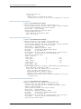
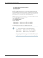
Merging a Full Example
To merge a full example, follow these steps:
1.
From the HTML or PDF version of the manual, copy a configuration example into a
text file, save the file with a name, and copy the file to a directory on your routing
platform.
For example, copy the following configuration to a file and name the file ex-script.conf.
Copy the ex-script.conf file to the /var/tmp directory on your routing platform.
system {
scripts {
commit {
file ex-script.xsl;
}
}
}
interfaces {
fxp0 {
disable;
unit 0 {
family inet {
address 10.0.0.1/24;
}
}
}
}
2. Merge the contents of the file into your routing platform configuration by issuing the
load merge configuration mode command:
[edit]
user@host# load merge /var/tmp/ex-script.conf
load complete
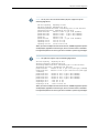
Merging a Snippet
To merge a snippet, follow these steps:
1.
From the HTML or PDF version of the manual, copy a configuration snippet into a text
file, save the file with a name, and copy the file to a directory on your routing platform.
For example, copy the following snippet to a file and name the file
ex-script-snippet.conf. Copy the ex-script-snippet.conf file to the /var/tmp directory
on your routing platform.
commit {
file ex-script-snippet.xsl; }
viii
Copyright © 2013, Juniper Networks, Inc.
About the Documentation
2. Move to the hierarchy level that is relevant for this snippet by issuing the following
configuration mode command:
[edit]
user@host# edit system scripts
[edit system scripts]
3. Merge the contents of the file into your routing platform configuration by issuing the
load merge relative configuration mode command:
[edit system scripts]
user@host# load merge relative /var/tmp/ex-script-snippet.conf
load complete
For more information about the load command, see the CLI User Guide.
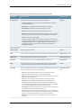
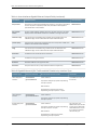
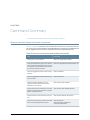
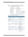
Documentation Conventions
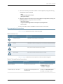
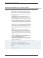
Table 1 on page ix defines notice icons used in this guide.
Table 1: Notice Icons
Icon
Meaning
Description
Informational note
Indicates important features or instructions.
Caution
Indicates a situation that might result in loss of data or hardware damage.
Warning
Alerts you to the risk of personal injury or death.
Laser warning
Alerts you to the risk of personal injury from a laser.
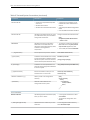
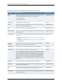
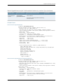
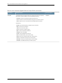
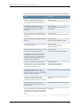
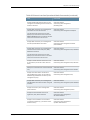
Table 2 on page ix defines the text and syntax conventions used in this guide.
Table 2: Text and Syntax Conventions
Convention
Description
Examples
Bold text like this
Represents text that you type.
To enter configuration mode, type
theconfigure command:
user@host> configure
Fixed-width text like this
Copyright © 2013, Juniper Networks, Inc.
Represents output that appears on the
terminal screen.
user@host> show chassis alarms
No alarms currently active
ix
Static ARP Table Entries Feature Guide for Routing Devices
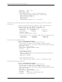
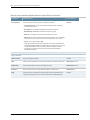
Table 2: Text and Syntax Conventions (continued)
Convention
Description
Examples
Italic text like this
•
Introduces or emphasizes important
new terms.
•
•
Identifies book names.
A policy term is a named structure
that defines match conditions and
actions.
•
Identifies RFC and Internet draft titles.
•
Junos OS System Basics Configuration
Guide
•
RFC 1997, BGP Communities Attribute
Italic text like this
Represents variables (options for which
you substitute a value) in commands or
configuration statements.
Configure the machine’s domain name:
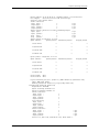
Represents names of configuration
statements, commands, files, and
directories; configuration hierarchy levels;
or labels on routing platform
components.
•
To configure a stub area, include the
stub statement at the[edit protocols
ospf area area-id] hierarchy level.
•
The console port is labeled CONSOLE.
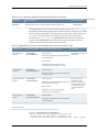
< > (angle brackets)
Enclose optional keywords or variables.
stub <default-metric metric>;
| (pipe symbol)
Indicates a choice between the mutually
exclusive keywords or variables on either
side of the symbol. The set of choices is
often enclosed in parentheses for clarity.
broadcast | multicast
# (pound sign)
Indicates a comment specified on the
same line as the configuration statement
to which it applies.
rsvp { # Required for dynamic MPLS only
[ ] (square brackets)
Enclose a variable for which you can
substitute one or more values.
community name members [
community-ids ]
Indention and braces ( { } )
Identify a level in the configuration
hierarchy.
; (semicolon)
Identifies a leaf statement at a
configuration hierarchy level.
Text like this
[edit]
root@# set system domain-name
domain-name
(string1 | string2 | string3)
[edit]
routing-options {
static {
route default {
nexthop address;
retain;
}
}
}
GUI Conventions
Bold text like this
> (bold right angle bracket)
x
Represents graphical user interface (GUI)
items you click or select.
Separates levels in a hierarchy of menu
selections.
•
In the Logical Interfaces box, select
All Interfaces.
•
To cancel the configuration, click
Cancel.
In the configuration editor hierarchy,
select Protocols>Ospf.
Copyright © 2013, Juniper Networks, Inc.
About the Documentation
Documentation Feedback
We encourage you to provide feedback, comments, and suggestions so that we can
improve the documentation. You can send your comments to
[email protected], or fill out the documentation feedback form at
https://www.juniper.net/cgi-bin/docbugreport/ . If you are using e-mail, be sure to include
the following information with your comments:
•
Document or topic name
•
URL or page number
•
Software release version (if applicable)
Requesting Technical Support
Technical product support is available through the Juniper Networks Technical Assistance
Center (JTAC). If you are a customer with an active J-Care or JNASC support contract,
or are covered under warranty, and need post-sales technical support, you can access
our tools and resources online or open a case with JTAC.
•
JTAC policies—For a complete understanding of our JTAC procedures and policies,
review the JTAC User Guide located at
http://www.juniper.net/us/en/local/pdf/resource-guides/7100059-en.pdf.
•
Product warranties—For product warranty information, visit
http://www.juniper.net/support/warranty/.
•
JTAC hours of operation—The JTAC centers have resources available 24 hours a day,
7 days a week, 365 days a year.
Self-Help Online Tools and Resources
For quick and easy problem resolution, Juniper Networks has designed an online
self-service portal called the Customer Support Center (CSC) that provides you with the
following features:
•
Find CSC offerings: http://www.juniper.net/customers/support/
•
Search for known bugs: http://www2.juniper.net/kb/
•
Find product documentation: http://www.juniper.net/techpubs/
•
Find solutions and answer questions using our Knowledge Base: http://kb.juniper.net/
•
Download the latest versions of software and review release notes:
http://www.juniper.net/customers/csc/software/
•
Search technical bulletins for relevant hardware and software notifications:
https://www.juniper.net/alerts/
Copyright © 2013, Juniper Networks, Inc.
xi
Static ARP Table Entries Feature Guide for Routing Devices
•
Join and participate in the Juniper Networks Community Forum:
http://www.juniper.net/company/communities/
•
Open a case online in the CSC Case Management tool: http://www.juniper.net/cm/
To verify service entitlement by product serial number, use our Serial Number Entitlement
(SNE) Tool: https://tools.juniper.net/SerialNumberEntitlementSearch/
Opening a Case with JTAC
You can open a case with JTAC on the Web or by telephone.
•
Use the Case Management tool in the CSC at http://www.juniper.net/cm/.
•
Call 1-888-314-JTAC (1-888-314-5822 toll-free in the USA, Canada, and Mexico).
For international or direct-dial options in countries without toll-free numbers, see
http://www.juniper.net/support/requesting-support.html.
xii
Copyright © 2013, Juniper Networks, Inc.
PART 1
Overview
•
Static ARP Table Entries on page 3
Copyright © 2013, Juniper Networks, Inc.
1
Static ARP Table Entries Feature Guide for Routing Devices
2
Copyright © 2013, Juniper Networks, Inc.
CHAPTER 1
Static ARP Table Entries
•
Static ARP Table Entries Overview on page 3
Static ARP Table Entries Overview
For Fast Ethernet, Gigabit Ethernet, Tri-Rate Ethernet copper, and 10-Gigabit Ethernet
interfaces, you can configure static ARP table entries, defining mappings between IP and
MAC addresses.
Related
Documentation
•
Configuring Static ARP Table Entries on page 7
•
Ethernet Interfaces
Copyright © 2013, Juniper Networks, Inc.
3
Static ARP Table Entries Feature Guide for Routing Devices
4
Copyright © 2013, Juniper Networks, Inc.
PART 2
Configuration
•
Static ARP Table Entries on page 7
•
Network Interfaces Configuration Statements and Hierarchy on page 9
•
Statement Summary on page 27
Copyright © 2013, Juniper Networks, Inc.
5
Static ARP Table Entries Feature Guide for Routing Devices
6
Copyright © 2013, Juniper Networks, Inc.
CHAPTER 2
Static ARP Table Entries
•
Configuring Static ARP Table Entries on page 7
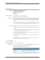
Configuring Static ARP Table Entries
To configure static ARP table entries, include the arp statement:
arp ip-address (mac | multicast-mac) mac-address <publish>;
You can include this statement at the following hierarchy levels:
•
[edit interfaces interface-name unit logical-unit-number family inet address address]
•
[edit logical-systems logical-system-name interfaces interface-name unit
logical-unit-number family inet address address]
The IP address that you specify must be part of the subnet defined in the enclosing
address statement.
To associate a multicast MAC address with a unicast IP address, include the multicast-mac
statement.
Specify the MAC address as six hexadecimal bytes in one of the following formats:
nnnn.nnnn.nnnn or nn:nn:nn:nn:nn:nn; for example, 0011.2233.4455 or 00:11:22:33:44:55.
For unicast MAC addresses only, if you include the publish option, the router or switch
replies to proxy ARP requests.
NOTE: By default, an ARP policer is installed that is shared among all the
Ethernet interfaces on which you have configured the family inet statement.
By including the arp statement at the [edit interfaces interface-name unit
logical-unit-number family inet policer] hierarchy level, you can apply a specific
ARP-packet policer to an interface. This feature is not available on EX Series
switches.
When you need to conserve IP addresses, you can configure an Ethernet
interface to be unnumbered by including the unnumbered-address statement
at the [edit interfaces interface-name unit logical-unit-number family inet]
hierarchy level.
Copyright © 2013, Juniper Networks, Inc.
7
Static ARP Table Entries Feature Guide for Routing Devices
NOTE: The Junos OS supports the IPv6 static neighbor discovery cache
entries, similar to the static ARP entries in IPv4.
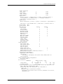
Example: Configuring Static ARP Table Entries
Configure two static ARP table entries on the router or switch’s management interface:
[edit interfaces]
fxp0 {
unit 0 {
family inet {
address 10.10.0.11/24 {
arp 10.10.0.99 mac 0001.0002.0003;
arp 10.10.0.101 mac 00:11:22:33:44:55 publish;
}
}
}
}
Related
Documentation
8
•
Management Ethernet Interface Overview
•
Applying Policers
•
Configuring an Unnumbered Interface
•
Ethernet Interfaces
Copyright © 2013, Juniper Networks, Inc.
CHAPTER 3
Network Interfaces Configuration
Statements and Hierarchy
•
[edit interfaces] Hierarchy Level on page 9
[edit interfaces] Hierarchy Level
The statements at the [edit interfaces interface-name unit logical-unit-number] hierarchy
level can also be configured at the [edit logical-systems logical-system-name interfaces
interface-name unit logical-unit-number] hierarchy level.
NOTE: The accounting-profile statement is an exception to this rule. The
accounting-profile statement can be configured at the [edit interfaces
interface-name unit logical-unit-number] hierarchy level, but it cannot be
configured at the [edit logical-systems logical-system-name interfaces
interface-name unit logical-unit-number] hierarchy level.
interfaces {
traceoptions {
file filename <files number> <match regular-expression> <size size> <world-readable |
no-world-readable> ;
flag flag <disable>;
}
interface-name {
account-layer2-overhead (Interface Level) {
value;
egress bytes;
ingress bytes;
}
accounting-profile name;
aggregated-ether-options {
(flow-control | no-flow-control);
lacp {
(active | passive);
link-protection {
disable;
(revertive | non-revertive);
periodic interval;
system-priority priority;
Copyright © 2013, Juniper Networks, Inc.
9
Static ARP Table Entries Feature Guide for Routing Devices
}
link-protection;
link-speed speed;
(loopback | no-loopback);
mc-ae{
chassis-id chassis-id;
mc-ae-id mc-ae-id;
mode (active-active | active-standby);
redundancy-group group-id;
status-control (active | standby);
}
minimum-links number;
source-address-filter {
mac-address;
}
(source-filtering | no-source-filtering);
}
shared-scheduler;
aggregated-sonet-options {
link-speed speed | mixed;
minimum-links number;
}
atm-options {
cell-bundle-size cells;
ilmi;
linear-red-profiles profile-name {
high-plp-max-threshold percent;
low-plp-max-threshold percent;
queue-depth cells high-plp-threshold percent low-plp-threshold percent;
}
mpls {
pop-all-labels {
required-depth number;
}
}
pic-type (atm1 | atm2);
plp-to-clp;
promiscuous-mode {
vpi vpi-identifier;
}
scheduler-maps map-name {
forwarding-class class-name {
epd-threshold cells plp1 cells;
linear-red-profile profile-name;
priority (high | low);
transmit-weight (cells number | percent number);
}
vc-cos-mode (alternate | strict);
}
use-null-cw;
vpi vpi-identifier {
maximum-vcs maximum-vcs;
oam-liveness {
down-count cells;
up-count cells;
}
10
Copyright © 2013, Juniper Networks, Inc.
Chapter 3: Network Interfaces Configuration Statements and Hierarchy
oam-period (seconds | disable);
shaping {
(cbr rate | rtvbr peak rate sustained rate burst length | vbr peak rate sustained rate
burst length);
queue-length number;
}
}
}
clocking clock-source;
data-input (system | interface interface-name);
dce;
serial-options {
clock-rate rate;
clocking-mode (dce | internal | loop);
control-polarity (negative | positive);
cts-polarity (negative | positive);
dcd-polarity (negative | positive);
dce-options {
control-signal (assert | de-assert | normal);
cts (ignore | normal | require);
dcd (ignore | normal | require);
dsr (ignore | normal | require);
dtr signal-handling-option;
ignore-all;
indication (ignore | normal | require);
rts (assert | de-assert | normal);
tm (ignore | normal | require);
}
dsr-polarity (negative | positive);
dte-options {
control-signal (assert | de-assert | normal);
cts (ignore | normal | require);
dcd (ignore | normal | require);
dsr (ignore | normal | require);
dtr signal-handling-option;
ignore-all;
indication (ignore | normal | require);
rts (assert | de-assert | normal);
tm (ignore | normal | require);
}
dtr-circuit (balanced | unbalanced);
dtr-polarity (negative | positive);
encoding (nrz | nrzi);
indication-polarity (negative | positive);
line-protocol protocol;
loopback mode;
rts-polarity (negative | positive);
tm-polarity (negative | positive);
transmit-clock invert;
}
description text;
dialer-options {
pool pool-name <priority priority>;
}
disable;
ds0-options {
Copyright © 2013, Juniper Networks, Inc.
11
Static ARP Table Entries Feature Guide for Routing Devices
bert-algorithm algorithm;
bert-error-rate rate;
bert-period seconds;
byte-encoding (nx56 | nx64);
fcs (16 | 32);
idle-cycle-flag (flags | ones);
invert-data;
loopback payload;
start-end-flag (filler | shared);
}
e1-options {
bert-error-rate rate;
bert-period seconds;
fcs (16 | 32);
framing (g704 | g704-no-crc4 | unframed);
idle-cycle-flag (flags | ones);
invert-data;
loopback (local | remote);
start-end-flag (filler | shared);
timeslots time-slot-range;
}
e3-options {
atm-encapsulation (direct | plcp);
bert-algorithm algorithm;
bert-error-rate rate;
bert-period seconds;
framing feet;
compatibility-mode (digital-link | kentrox | larscom) <subrate value>;
fcs (16 | 32);
framing (g.751 | g.832);
idle-cycle-flag (filler | shared);
invert-data;
loopback (local | remote);
(payload-scrambler | no-payload-scrambler);
start-end-flag (filler | shared);
(unframed | no-unframed);
}
encapsulation type;
es-options {
backup-interface es-fpc/pic/port;
}
fastether-options {
802.3ad aex;
(flow-control | no-flow-control);
ignore-l3-incompletes;
ingress-rate-limit rate;
(loopback | no-loopback);
mpls {
pop-all-labels {
required-depth number;
}
}
source-address-filter {
mac-address;
}
(source-filtering | no-source-filtering);
12
Copyright © 2013, Juniper Networks, Inc.
Chapter 3: Network Interfaces Configuration Statements and Hierarchy
}
flexible-vlan-tagging;
gigether-options {
802.3ad aex;
(asynchronous-notification | no-asynchronous-notification);
(auto-negotiation | no-auto-negotiation) remote-fault <local-interface-online |
local-interface-offline>;
auto-reconnect seconds;
(flow-control | no-flow-control);
ignore-l3-incompletes;
(loopback | no-loopback);
mpls {
pop-all-labels {
required-depth number;
}
}
no-auto-mdix;
source-address-filter {
mac-address;
}
(source-filtering | no-source-filtering);
ethernet-switch-profile {
(mac-learn-enable | no-mac-learn-enable);
tag-protocol-id [ tpids ];
ethernet-policer-profile {
input-priority-map {
ieee802.1p premium [ values ];
}
output-priority-map {
classifier {
premium {
forwarding-class class-name {
loss-priority (high | low);
}
}
}
}
policer cos-policer-name {
aggregate {
bandwidth-limit bps;
burst-size-limit bytes;
}
premium {
bandwidth-limit bps;
burst-size-limit bytes;
}
}
}
}
}
(gratuitous-arp-reply | no-gratuitous-arp-reply);
hold-time up milliseconds down milliseconds;
ima-group-options {
differential-delay number;
frame-length (32 | 64 | 128 | 256);
frame-synchronization {
Copyright © 2013, Juniper Networks, Inc.
13
Static ARP Table Entries Feature Guide for Routing Devices
alpha number;
beta number;
gamma number;
}
minimum-links number;
symmetry (symmetrical-config-and-operation |
symmetrical-config-asymmetrical-operation);
test-procedure {
ima-test-start;
ima-test-stop;
interface name;
pattern number;
period number;
}
transmit-clock (common | independent);
version (1.0 |1.1);
}
ima-link-options group-id group-id;
interface-set interface-set-name {
interface ethernet-interface-name {
(unit unit-number | vlan-tags-outer vlan-tag);
}
interface interface-name {
(unit unit-number);
}
}
isdn-options {
bchannel-allocation (ascending | descending);
calling-number number;
pool pool-name <priority priority>;
spid1 spid-string;
spid2 spid-string;
static-tei-val value;
switch-type (att5e | etsi | ni1 | ntdms100 | ntt);
t310 seconds;
tei-option (first-call | power-up);
}
keepalives <down-count number> <interval seconds> <up-count number>;
link-mode mode;
lmi {
lmi-type (ansi | itu | c-lmi);
n391dte number;
n392dce number;
n392dte number;
n393dce number;
n393dte number;
t391dte seconds;
t392dce seconds;
}
lsq-failure-options {
no-termination-request;
[ trigger-link-failure interface-name ];
}
mac mac-address;
mlfr-uni-nni-bundle-options {
acknowledge-retries number;
14
Copyright © 2013, Juniper Networks, Inc.
Chapter 3: Network Interfaces Configuration Statements and Hierarchy
acknowledge-timer milliseconds;
action-red-differential-delay (disable-tx | remove-link);
drop-timeout milliseconds;
fragment-threshold bytes;
cisco-interoperability send-lip-remove-link-for-link-reject;
hello-timer milliseconds;
link-layer-overhead percent;
lmi-type (ansi | itu | c-lmi);
minimum-links number;
mrru bytes;
n391 number;
n392 number;
n393 number;
red-differential-delay milliseconds;
t391 seconds;
t392 seconds;
yellow-differential-delay milliseconds;
}
modem-options {
dialin (console | routable);
init-command-string initialization-command-string;
}
mtu bytes;
multi-chassis-protection {
peer a.b.c.d {
interfaceinterface-name;
}
}
multiservice-options {
(core-dump | no-core-dump);
(syslog | no-syslog);
}
native-vlan-id number;
no-gratuitous-arp-request;
no-keepalives;
no-partition {
interface-type type;
}
no-vpivci-swapping;
optics-options {
alarm low-light-alarm {
(link-down | syslog);
}
tx-power dbm;
warning low-light-warning {
(link-down | syslog);
}
wavelength nm;
}
otn-options {
bytes transmit-payload-type value;
fec (efec | gfec | gfec-sdfec | none);
(is-ma | no-is-ma);
(laser-enable | no-laser-enable);
(line-loopback | no-line-loopback);
(local-loopback | no-local-loopback);
Copyright © 2013, Juniper Networks, Inc.
15
Static ARP Table Entries Feature Guide for Routing Devices
(odu-ttim-action-enable | no-odu-ttim-action-enable);
(otu-ttim-action-enable | no-otu-ttim-action-enable);
odu-delay-management {
(bypass | no-bypass);
(monitor-end-point | no-monitor-end-point);
(number-of-frames | no-number-of-frames);
(start-measurement | no-start-measurement);
}
(prbs | no-prbs);
preemptive-fast-reroute {
(backward-frr-enable | no-backward-frr-enable);
(signal-degrade-monitor-enable | no-signal-degrade-monitor-enable);
}
rate {
(fixed-stuff-bytes | no-fixed-stuff-bytes);
otu4;
(pass-through | no-pass-through);
}
signal-degrade {
ber-threshold-clear value;
ber-threshold-signal-degrade value;
interval value;
}
trigger trigger-identifier;
tti tti-identifier;
}
partition partition-number oc-slice oc-slice-range interface-type type;
timeslots time-slot-range;
passive-monitor-mode;
per-unit-scheduler;
ppp-options {
chap {
access-profile name;
default-chap-secret name;
local-name name;
passive;
}
compression {
acfc;
pfc;
}
dynamic-profile profile-name;
no-termination-request;
pap {
access-profile name;
local-name name;
local-password password;
compression;
}
}
psn-vcipsn-vci-identifier;
psn-vpipsn-vpi-identifier;
receive-bucket {
overflow (discard | tag);
rate percentage;
threshold bytes;
16
Copyright © 2013, Juniper Networks, Inc.
Chapter 3: Network Interfaces Configuration Statements and Hierarchy
}
redundancy-options {
priority sp-fpc/pic/port;
secondary sp-fpc/pic/port;
hot-standby;
}
satop-options {
payload-size n;
}
schedulers number;
serial-options {
clock-rate rate;
clocking-mode (dce | internal | loop);
control-polarity (negative | positive);
cts-polarity (negative | positive);
dcd-polarity (negative | positive);
dce-options {
control-signal (assert | de-assert | normal);
cts (ignore | normal | require);
dcd (ignore | normal | require);
dsr (ignore | normal | require);
dtr signal-handling-option;
ignore-all;
indication (ignore | normal | require);
rts (assert | de-assert | normal);
tm (ignore | normal | require);
}
dsr-polarity (negative | positive);
dte-options {
control-signal (assert | de-assert | normal);
cts (ignore | normal | require);
dcd (ignore | normal | require);
dsr (ignore | normal | require);
dtr signal-handling-option;
ignore-all;
indication (ignore | normal | require);
rts (assert | de-assert | normal);
tm (ignore | normal | require);
}
dtr-circuit (balanced | unbalanced);
dtr-polarity (negative | positive);
encoding (nrz | nrzi);
indication-polarity (negative | positive);
line-protocol protocol;
loopback mode;
rts-polarity (negative | positive);
tm-polarity (negative | positive);
transmit-clock invert;
}
services-options {
inactivity-timeout seconds;
open-timeout seconds;
session-limit {
maximum number;
rate new-sessions-per-second;
}
Copyright © 2013, Juniper Networks, Inc.
17
Static ARP Table Entries Feature Guide for Routing Devices
syslog {
host hostname {
facility-override facility-name;
log-prefix prefix-number;
services priority-level;
}
}
}
shdsl-options {
annex (annex-a | annex-b);
line-rate line-rate;
loopback (local | remote);
snr-margin {
current margin;
snext margin;
}
}
sonet-options {
aggregate asx;
aps {
advertise-interval milliseconds;
annex-b;
authentication-key key;
fast-aps-switch;
force;
hold-time milliseconds;
lockout;
neighbor address;
paired-group group-name;
preserve-interface;
protect-circuit group-name;
request;
revert-time seconds;
switching-mode (bidirectional | unidirectional);
working-circuit group-name;
}
bytes {
c2 value;
e1-quiet value;
f1 value;
f2 value;
s1 value;
z3 value;
z4 value;
}
fcs (16 | 32);
loopback (local | remote);
mpls {
pop-all-labels {
required-depth number;
}
}
path-trace trace-string;
(payload-scrambler | no-payload-scrambler);
rfc-2615;
trigger {
18
Copyright © 2013, Juniper Networks, Inc.
Chapter 3: Network Interfaces Configuration Statements and Hierarchy
defect ignore;
hold-time up milliseconds down milliseconds;
}
vtmapping (itu-t | klm);
(z0-increment | no-z0-increment);
}
speed (10m | 100m | 1g | oc3 | oc12 | oc48);
stacked-vlan-tagging;
switch-options {
switch-port port-number {
(auto-negotiation | no-auto-negotiation);
speed (10m | 100m | 1g);
link-mode (full-duplex | half-duplex);
}
}
t1-options {
bert-algorithm algorithm;
bert-error-rate rate;
bert-period seconds;
buildout value;
byte-encoding (nx56 | nx64);
crc-major-alarm-threshold (1e-3 | 5e-4 | 1e-4 | 5e-5 | 1e-5);
crc-minor-alarm-threshold (1e-3 | 5e-4 | 1e-4 | 5e-5 | 1e-5 | 5e-6 | 1e-6);
fcs (16 | 32);
framing (esf | sf);
idle-cycle-flag (flags | ones);
invert-data;
line-encoding (ami | b8zs);
loopback (local | payload | remote);
remote-loopback-respond;
start-end-flag (filler | shared);
timeslots time-slot-range;
}
t3-options {
atm-encapsulation (direct | plcp);
bert-algorithm algorithm;
bert-error-rate rate;
bert-period seconds;
buildout feet;
(cbit-parity | no-cbit-parity);
compatibility-mode (adtran | digital-link | kentrox | larscom | verilink) <subrate
value>;
fcs (16 | 32);
(feac-loop-respond | no-feac-loop-respond);
idle-cycle-flag value;
(long-buildout | no-long-buildout);
(loop-timing | no-loop-timing);
loopback (local | payload | remote);
(mac | no-mac);
(payload-scrambler | no-payload-scrambler);
start-end-flag (filler | shared);
}
traceoptions {
flag flag <flag-modifier> <disable>;
}
transmit-bucket {
Copyright © 2013, Juniper Networks, Inc.
19
Static ARP Table Entries Feature Guide for Routing Devices
overflow discard;
rate percentage;
threshold bytes;
}
(traps | no-traps);
unidirectional;
vlan-tagging;
vlan-vci-tagging;
unit logical-unit-number {
accept-source-mac {
mac-address mac-address {
policer {
input cos-policer-name;
output cos-policer-name;
}
}
}
account-layer2-overhead {
value;
egress bytes;
ingress bytes;
}
accounting-profile name;
advisory-options {
downstream-rate rate;
upstream-rate rate;
}
allow-any-vci;
atm-scheduler-map (map-name | default);
backup-options {
interface interface-name;
}
bandwidth rate;
cell-bundle-size cells;
clear-dont-fragment-bit;
compression {
rtp {
f-max-period number;
maximum-contexts number <force>;
queues [ queue-numbers ];
port {
minimum port-number;
maximum port-number;
}
}
}
compression-device interface-name;
copy-tos-to-outer-ip-header;
demux-destination family;
demux-source family;
demux-options {
underlying-interface interface-name;
}
description text;
interface {
l2tp-interface-id name;
20
Copyright © 2013, Juniper Networks, Inc.
Chapter 3: Network Interfaces Configuration Statements and Hierarchy
(dedicated | shared);
}
dialer-options {
activation-delay seconds;
callback;
callback-wait-period time;
deactivation-delay seconds;
dial-string [ dial-string-numbers ];
idle-timeout seconds;
incoming-map {
caller (caller-id | accept-all);
initial-route-check seconds;
load-interval seconds;
load-threshold percent;
pool pool-name;
redial-delay time;
watch-list {
[ routes ];
}
}
}
disable;
disable-mlppp-inner-ppp-pfc;
dlci dlci-identifier;
drop-timeout milliseconds;
dynamic-call-admission-control {
activation-priority priority;
bearer-bandwidth-limit kilobits-per-second;
}
encapsulation type;
epd-threshold cells plp1 cells;
fragment-threshold bytes;
inner-vlan-id-range start start-id end end-id;
input-vlan-map {
(pop | pop-pop | pop-swap | push | push-push | swap | swap-push | swap-swap);
inner-tag-protocol-id tpid;
inner-vlan-id number;
tag-protocol-id tpid;
vlan-id number;
}
interleave-fragments;
inverse-arp;
layer2-policer {
input-policer policer-name;
input-three-color policer-name;
output-policer policer-name;
output-three-color policer-name;
}
link-layer-overhead percent;
minimum-links number;
mrru bytes;
multicast-dlci dlci-identifier;
multicast-vci vpi-identifier.vci-identifier;
multilink-max-classes number;
multipoint;
oam-liveness {
Copyright © 2013, Juniper Networks, Inc.
21
Static ARP Table Entries Feature Guide for Routing Devices
down-count cells;
up-count cells;
}
oam-period (seconds | disable);
output-vlan-map {
(pop | pop-pop | pop-swap | push | push-push | swap | swap-push | swap-swap);
inner-tag-protocol-id tpid;
inner-vlan-id number;
tag-protocol-id tpid;
vlan-id number;
}
passive-monitor-mode;
peer-unit unit-number;
plp-to-clp;
point-to-point;
ppp-options {
chap {
access-profile name;
default-chap-secret name;
local-name name;
passive;
}
compression {
acfc;
pfc;
pap;
default-pap-password password;
local-name name;
local-password password;
passive;
}
dynamic-profile profile-name;
lcp-max-conf-req number;
lcp-restart-timer milliseconds;
loopback-clear-timer seconds;
ncp-max-conf-req number;
ncp-restart-timer milliseconds;
}
pppoe-options {
access-concentrator name;
auto-reconnect seconds;
(client | server);
service-name name;
underlying-interface interface-name;
}
proxy-arp;
service-domain (inside | outside);
shaping {
(cbr rate | rtvbr peak rate sustained rate burst length | vbr peak rate sustained rate
burst length);
queue-length number;
}
short-sequence;
transmit-weight number;
(traps | no-traps);
trunk-bandwidth rate;
22
Copyright © 2013, Juniper Networks, Inc.
Chapter 3: Network Interfaces Configuration Statements and Hierarchy
trunk-id number;
tunnel {
backup-destination address;
destination address;
key number;
routing-instance {
destination routing-instance-name;
}
source source-address;
ttl number;
}
vci vpi-identifier.vci-identifier;
vci-range start start-vci end end-vci;
vpi vpi-identifier;
vlan-id number;
vlan-id-list [vlan-id vlan-id–vlan-id];
vlan-id-range number-number;
vlan-tags inner tpid.vlan-id outer tpid.vlan-id;
vlan-tags-outer tpid.vlan-id inner-list [vlan-id vlan-id–vlan-id];
family family {
accounting {
destination-class-usage;
source-class-usage {
direction;
}
}
access-concentrator name;
address address {
destination address;
}
bundle ml-fpc/pic/port | ls-fpc/pic/port);
duplicate-protection;
dynamic-profile profile-name;
filter {
group filter-group-number;
input filter-name;
input-list {
[ filter-names ];
output filter-name;
}
output-list {
[ filter-names ];
}
}
ipsec-sa sa-name;
keep-address-and-control;
max-sessions number;
max-sessions-vsa-ignore;
mtu bytes;
multicast-only;
negotiate-address;
no-redirects;
policer {
arp policer-template-name;
input policer-template-name;
output policer-template-name;
Copyright © 2013, Juniper Networks, Inc.
23
Static ARP Table Entries Feature Guide for Routing Devices
}
primary;
proxy inet-address address;
receive-options-packets;
receive-ttl-exceeded;
remote (inet-address address | mac-address address);
rpf-check {
fail-filter filter-name;
mode loose;
}
sampling {
direction;
}
service {
input {
service-set service-set-name <service-filter filter-name>;
post-service-filter filter-name;
}
output {
service-set service-set-names <service-filter filter-name>;
}
}
service-name-table table-name;
short-cycle-protection <lockout-time-min minimum-seconds lockout-time-max
maximum-seconds>;
targeted-broadcast {
forward-and-send-to-re;
forward-only;
}
(translate-discard-eligible | no-translate-discard-eligible);
(translate-fecn-and-becn | no-translate-fecn-and-becn);
translate-plp-control-word-de;
unnumbered-address interface-name <destination address destination-profile
profile-name | preferred-source-address address>;
address address {
arp ip-address (mac | multicast-mac) mac-address <publish>;
broadcast address;
destination address;
destination-profile name;
eui-64;
multipoint-destination address (dlci dlci-identifier | vci vci-identifier);
multipoint-destination address {
epd-threshold cells plp1 cells;
inverse-arp;
oam-liveness {
up-count cells;
down-count cells;
}
oam-period (seconds | disable);
shaping {
(cbr rate | rtvbr peak rate sustained rate burst length | vbr peak rate sustained
rate burst length);
queue-length number;
}
vci vpi-identifier.vci-identifier;
}
24
Copyright © 2013, Juniper Networks, Inc.
Chapter 3: Network Interfaces Configuration Statements and Hierarchy
preferred;
primary;
(vrrp-group | vrrp-inet6-group) group-number {
(accept-data | no-accept-data);
advertise–interval seconds;
authentication-type authentication;
authentication-key key;
fast-interval milliseconds;
(preempt | no-preempt) {
hold-time seconds;
}
priority-number number;
track {
priority-cost seconds;
priority-hold-time interface-name {
bandwidth-threshold bits-per-second {
priority;
}
interface priority;
}
route ip-address/mask routing-instance instance-name priority-cost cost;
}
virtual-address [ addresses ];
}
}
}
}
}
}
Related
Documentation
•
Junos OS Hierarchy and RFC Reference
•
Ethernet Interfaces
•
Junos OS Network Interfaces Library for Routing Devices
Copyright © 2013, Juniper Networks, Inc.
25
Static ARP Table Entries Feature Guide for Routing Devices
26
Copyright © 2013, Juniper Networks, Inc.
CHAPTER 4
Statement Summary
Copyright © 2013, Juniper Networks, Inc.
27
Static ARP Table Entries Feature Guide for Routing Devices
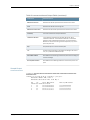
arp (Interfaces)
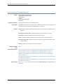
Syntax
Hierarchy Level
Release Information
Description
Options
arp ip-address (mac | multicast-mac) mac-address publish;
[edit interfaces interface-name unit logical-unit-numberfamily inetaddress address],
[edit logical-systems logical-system-name interfaces interface-nameunit logical-unit-number
family inetaddress address]
Statement introduced before Junos OS Release 7.4.
Statement introduced in Junos OS Release 9.0 for EX Series switches.
Statement introduced in Junos OS Release 11.1 for the QFX Series.
For Ethernet, Fast Ethernet, and Gigabit Ethernet interfaces only, configure Address
Resolution Protocol (ARP) table entries, mapping IP addresses to MAC addresses.
ip-address—IP address to map to the MAC address. The IP address specified must be
part of the subnet defined in the enclosing address statement.
mac mac-address—MAC address to map to the IP address. Specify the MAC address as
six hexadecimal bytes in one of the following formats: nnnn.nnnn.nnnn or
nn:nn:nn:nn:nn:nn. For example, 0011.2233.4455 or 00:11:22:33:44:55.
multicast-mac mac-address—Multicast MAC address to map to the IP address. Specify
the multicast MAC address as six hexadecimal bytes in one of the following formats:
nnnn.nnnn.nnnn or nn:nn:nn:nn:nn:nn. For example, 0011.2233.4455 or 00:11:22:33:44:55.
publish—(Optional) Have the router or switch reply to ARP requests for the specified IP
address. If you omit this option, the router or switch uses the entry to reach the
destination but does not reply to ARP requests.
NOTE: The edit logical-systems hierarchy is not available on QFabric systems.
Required Privilege
Level
Related
Documentation
28
interface—To view this statement in the configuration.
interface-control—To add this statement to the configuration.
•
Configuring Static ARP Table Entries on page 7
•
Configuring Static ARP Entries
Copyright © 2013, Juniper Networks, Inc.
Chapter 4: Statement Summary
fast-aps-switch
Syntax
Hierarchy Level
Release Information
Description
fast-aps-switch;
[edit interfaces interface-name sonet-options aps]
Statement introduced in Junos OS Release 12.1.
(M320 routers with Channelized OC3/STM1 Circuit Emulation PIC with SFP only and EX
Series switches) Reduce the Automatic Protection Switching (APS) switchover time in
Layer 2 circuits.
NOTE:
Required Privilege
Level
Related
Documentation
•
Configuring this statement reduces the APS switchover time only when
the Layer 2 circuit encapsulation type for the interface receiving traffic from
a Layer 2 circuit neighbor is SAToP.
•
When the fast-aps-switch statement is configured in revertive APS mode,
you must configure an appropriate value for revert time to achieve reduction
in APS switchover time.
•
To prevent the logical interfaces in the data path from being shut down,
configure appropriate hold-time values on all the interfaces in the data
path that support TDM.
•
The fast-aps-switch statement cannot be configured when the APS annex-b
option is configured.
•
The interfaces that have the fast-aps-switch statement configured cannot
be used in virtual private LAN service (VPLS) environments.
interface—To view this statement in the configuration.
interface-control—To add this statement to the configuration.
•
Reducing APS Switchover Time in Layer 2 Circuits
Copyright © 2013, Juniper Networks, Inc.
29
Static ARP Table Entries Feature Guide for Routing Devices
30
Copyright © 2013, Juniper Networks, Inc.
PART 3
Administration
•
Monitoring Commands on page 33
•
Command Summary on page 97
Copyright © 2013, Juniper Networks, Inc.
31
Static ARP Table Entries Feature Guide for Routing Devices
32
Copyright © 2013, Juniper Networks, Inc.
CHAPTER 5
Monitoring Commands
Copyright © 2013, Juniper Networks, Inc.
33
Static ARP Table Entries Feature Guide for Routing Devices
show interfaces (Fast Ethernet)
Syntax
Release Information
Description
Options
show interfaces interface-type
<brief | detail | extensive | terse>
<descriptions>
<media>
<snmp-index snmp-index>
<statistics>
Command introduced before Junos OS Release 7.4.
Display status information about the specified Fast Ethernet interface.
interface-type—On M Series and T Series routers, the interface type is fe-fpc/pic/port. On
the J Series routers, the interface type is fe-pim/0/port.
brief | detail | extensive | terse—(Optional) Display the specified level of output.
descriptions—(Optional) Display interface description strings.
media—(Optional) Display media-specific information about network interfaces.
snmp-index snmp-index—(Optional) Display information for the specified SNMP index
of the interface.
statistics—(Optional) Display static interface statistics.
Required Privilege
Level
List of Sample Output
Output Fields
view
show interfaces (Fast Ethernet) on page 47
show interfaces brief (Fast Ethernet) on page 48
show interfaces detail (Fast Ethernet) on page 48
show interfaces extensive (Fast Ethernet) on page 48
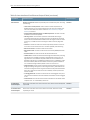
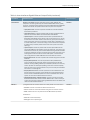
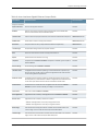
Table 3 on page 34 lists the output fields for the show interfaces Fast Ethernet command.
Output fields are listed in the approximate order in which they appear.
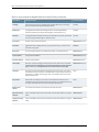
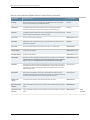
Table 3: show interfaces Fast Ethernet Output Fields
Field Name
Field Description
Level of Output
Physical interface
Name of the physical interface.
All levels
Enabled
State of the interface. Possible values are described in the “Enabled Field”
section under Common Output Fields Description.
All levels
Interface index
Index number of the physical interface, which reflects its initialization sequence.
detail extensive none
SNMP ifIndex
SNMP index number for the physical interface.
detail extensive none
Physical Interface
34
Copyright © 2013, Juniper Networks, Inc.
Chapter 5: Monitoring Commands
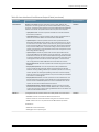
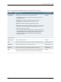
Table 3: show interfaces Fast Ethernet Output Fields (continued)
Field Name
Field Description
Level of Output
Generation
Unique number for use by Juniper Networks technical support only.
detail extensive
Link-level type
Encapsulation being used on the physical interface.
All levels
MTU
Maximum transmission unit size on the physical interface.
All levels
Link-mode
Type of link connection configured for the physical interface: Full-duplex or
extensive
Half-duplex
Speed
Speed at which the interface is running.
All levels
Loopback
Loopback status: Enabled or Disabled. If loopback is enabled, type of loopback:
Local or Remote.
All levels
Source filtering
Source filtering status: Enabled or Disabled.
All levels
LAN-PHY mode
10-Gigabit Ethernet interface operating in Local Area Network Physical Layer
Device (LAN PHY) mode. LAN PHY allows 10-Gigabit Ethernet wide area links
to use existing Ethernet applications.
All levels
WAN-PHY mode
10-Gigabit Ethernet interface operating in Wide Area Network Physical Layer
Device (WAN PHY) mode. WAN PHY allows 10-Gigabit Ethernet wide area links
to use fiber-optic cables and other devices intended for SONET/SDH.
All levels
Unidirectional
Unidirectional link mode status for 10-Gigabit Ethernet interface: Enabled or
Disabled for parent interface; Rx-only or Tx-only for child interfaces.
All levels
Flow control
Flow control status: Enabled or Disabled.
All levels
Auto-negotiation
(Gigabit Ethernet interfaces) Autonegotiation status: Enabled or Disabled.
All levels
Remote-fault
(Gigabit Ethernet interfaces) Remote fault status:
All levels
•
Online—Autonegotiation is manually configured as online.
•
Offline—Autonegotiation is manually configured as offline.
Device flags
Information about the physical device. Possible values are described in the
“Device Flags” section under Common Output Fields Description.
All levels
Interface flags
Information about the interface. Possible values are described in the “Interface
Flags” section under Common Output Fields Description.
All levels
Link flags
Information about the link. Possible values are described in the “Links Flags”
section under Common Output Fields Description.
All levels
Wavelength
(10-Gigabit Ethernet dense wavelength-division multiplexing [DWDM]
interfaces) Displays the configured wavelength, in nanometers (nm).
All levels
Copyright © 2013, Juniper Networks, Inc.
35
Static ARP Table Entries Feature Guide for Routing Devices
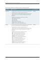
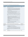
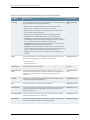
Table 3: show interfaces Fast Ethernet Output Fields (continued)
Field Name
Field Description
Level of Output
Frequency
(10-Gigabit Ethernet DWDM interfaces only) Displays the frequency associated
with the configured wavelength, in terahertz (THz).
All levels
CoS queues
Number of CoS queues configured.
detail extensive none
Schedulers
(GigabitEthernet intelligent queuing 2 (IQ2) interfaces only) Number of CoS
schedulers configured.
extensive
Hold-times
Current interface hold-time up and hold-time down, in milliseconds.
detail extensive
Current address
Configured MAC address.
detail extensive none
Hardware address
Hardware MAC address.
detail extensive none
Last flapped
Date, time, and how long ago the interface went from down to up. The format
is Last flapped: year-month-day hour:minute:second:timezone (hour:minute:second
ago). For example, Last flapped: 2002-04-26 10:52:40 PDT (04:33:20 ago).
detail extensive none
Input Rate
Input rate in bits per second (bps) and packets per second (pps).
None specified
Output Rate
Output rate in bps and pps.
None specified
Statistics last
cleared
Time when the statistics for the interface were last set to zero.
detail extensive
Traffic statistics
Number and rate of bytes and packets received and transmitted on the physical
interface.
detail extensive
•
Input bytes—Number of bytes received on the interface
•
Output bytes—Number of bytes transmitted on the interface.
•
Input packets—Number of packets received on the interface.
•
Output packets—Number of packets transmitted on the interface.
Gigabit Ethernet and 10-Gigabit Ethernet IQ PICs count the overhead and CRC
bytes.
For Gigabit Ethernet IQ PICs, the input byte counts vary by interface type. For
more information, see Table 31 under the show interfaces (10-Gigabit Ethernet)
command.
36
Copyright © 2013, Juniper Networks, Inc.
Chapter 5: Monitoring Commands
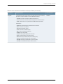
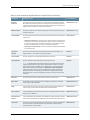
Table 3: show interfaces Fast Ethernet Output Fields (continued)
Field Name
Field Description
Level of Output
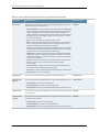
Input errors
Input errors on the interface. The following paragraphs explain the counters
whose meaning might not be obvious:
extensive
•
Errors—Sum of the incoming frame aborts and FCS errors.
•
Drops—Number of packets dropped by the input queue of the I/O Manager
ASIC. If the interface is saturated, this number increments once for every
packet that is dropped by the ASIC's RED mechanism.
•
Framing errors—Number of packets received with an invalid frame checksum
(FCS).
•
Runts—Number of frames received that are smaller than the runt threshold.
•
Policed discards—Number of frames that the incoming packet match code
discarded because they were not recognized or not of interest. Usually, this
field reports protocols that the Junos OS does not handle.
•
L3 incompletes—Number of incoming packets discarded because they failed
Layer 3 (usually IPv4) sanity checks of the header. For example, a frame with
less than 20 bytes of available IP header is discarded. L3 incomplete errors
can be ignored by configuring the ignore-l3-incompletes statement.
•
L2 channel errors—Number of times the software did not find a valid logical
interface for an incoming frame.
•
L2 mismatch timeouts—Number of malformed or short packets that caused
the incoming packet handler to discard the frame as unreadable.
•
FIFO errors—Number of FIFO errors in the receive direction that are reported
by the ASIC on the PIC. If this value is ever nonzero, the PIC is probably
malfunctioning.
•
Resource errors—Sum of transmit drops.
Copyright © 2013, Juniper Networks, Inc.
37
Static ARP Table Entries Feature Guide for Routing Devices
Table 3: show interfaces Fast Ethernet Output Fields (continued)
Field Name
Field Description
Level of Output
Output errors
Output errors on the interface. The following paragraphs explain the counters
whose meaning might not be obvious:
extensive
•
Carrier transitions—Number of times the interface has gone from down to up.
This number does not normally increment quickly, increasing only when the
cable is unplugged, the far-end system is powered down and then up, or
another problem occurs. If the number of carrier transitions increments quickly
(perhaps once every 10 seconds), the cable, the far-end system, or the PIC
or PIM is malfunctioning.
•
Errors—Sum of the outgoing frame aborts and FCS errors.
•
Drops—Number of packets dropped by the output queue of the I/O Manager
ASIC. If the interface is saturated, this number increments once for every
packet that is dropped by the ASIC's RED mechanism.
•
Collisions—Number of Ethernet collisions. The Gigabit Ethernet PIC supports
only full-duplex operation, so for Gigabit Ethernet PICs, this number should
always remain 0. If it is nonzero, there is a software bug.
•
Aged packets—Number of packets that remained in shared packet SDRAM
so long that the system automatically purged them. The value in this field
should never increment. If it does, it is most likely a software bug or possibly
malfunctioning hardware.
•
FIFO errors—Number of FIFO errors in the send direction as reported by the
ASIC on the PIC. If this value is ever nonzero, the PIC is probably
malfunctioning.
•
HS link CRC errors—Number of errors on the high-speed links between the
ASICs responsible for handling the router interfaces.
•
MTU errors—Number of packets whose size exceeded the MTU of the interface.
•
Resource errors—Sum of transmit drops.
Egress queues
Total number of egress queues supported on the specified interface.
detail extensive
Queue counters
(Egress)
CoS queue number and its associated user-configured forwarding class name.
detail extensive
•
Queued packets—Number of queued packets.
•
Transmitted packets—Number of transmitted packets.
•
Dropped packets—Number of packets dropped by the ASIC's RED mechanism.
Ingress queues
Total number of ingress queues supported on the specified interface. Displayed
on IQ2 interfaces.
extensive
Queue counters
(Ingress)
CoS queue number and its associated user-configured forwarding class name.
Displayed on IQ2 interfaces.
extensive
38
•
Queued packets—Number of queued packets.
•
Transmitted packets—Number of transmitted packets.
•
Dropped packets—Number of packets dropped by the ASIC's RED mechanism.
Copyright © 2013, Juniper Networks, Inc.
Chapter 5: Monitoring Commands
Table 3: show interfaces Fast Ethernet Output Fields (continued)
Field Name
Field Description
Level of Output
Active alarms and
Active defects
Ethernet-specific defects that can prevent the interface from passing packets.
When a defect persists for a certain amount of time, it is promoted to an alarm.
Based on the routing device configuration, an alarm can ring the red or yellow
alarm bell on the routing device, or turn on the red or yellow alarm LED on the
craft interface. These fields can contain the value None or Link.
detail extensive none
•
None—There are no active defects or alarms.
•
Link—Interface has lost its link state, which usually means that the cable is
unplugged, the far-end system has been turned off, or the PIC is
malfunctioning.
OTN FEC statistics
The forward error correction (FEC) counters provide the following statistics:.
•
Corrected Errors—The count of corrected errors in the last second.
•
Corrected Error Ratio—The corrected error ratio in the last 25 seconds. For
example, 1e-7 is 1 error per 10 million bits.
PCS statistics
(10-Gigabit Ethernet interfaces) Displays Physical Coding Sublayer (PCS) fault
conditions from the WAN PHY or the LAN PHY device.
•
detail extensive
Bit errors—High bit error rate. Indicates the number of bit errors when the PCS
receiver is operating in normal mode.
•
Errored blocks—Loss of block lock. The number of errored blocks when PCS
receiver is operating in normal mode.
Copyright © 2013, Juniper Networks, Inc.
39
Static ARP Table Entries Feature Guide for Routing Devices
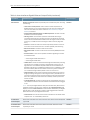
Table 3: show interfaces Fast Ethernet Output Fields (continued)
Field Name
Field Description
Level of Output
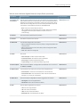
MAC statistics
Receive and Transmit statistics reported by the PIC's MAC subsystem, including
extensive
the following:
•
Total octets and total packets—Total number of octets and packets. For
Gigabit Ethernet IQ PICs, the received octets count varies by interface type.
For more information, see Table 31 under the show interfaces (10-Gigabit
Ethernet) command.
•
Unicast packets, Broadcast packets, and Multicast packets—Number of unicast,
broadcast, and multicast packets.
•
CRC/Align errors—Total number of packets received that had a length
(excluding framing bits, but including FCS octets) of between 64 and 1518
octets, inclusive, and had either a bad FCS with an integral number of octets
(FCS Error) or a bad FCS with a nonintegral number of octets (Alignment
Error).
•
FIFO error—Number of FIFO errors that are reported by the ASIC on the PIC.
If this value is ever nonzero, the PIC or a cable is probably malfunctioning.
•
MAC control frames—Number of MAC control frames.
•
MAC pause frames—Number of MAC control frames with pause operational
code.
•
Oversized frames—Number of frames that exceed 1518 octets.
•
Jabber frames—Number of frames that were longer than 1518 octets (excluding
framing bits, but including FCS octets), and had either an FCS error or an
alignment error. This definition of jabber is different from the definition in
IEEE-802.3 section 8.2.1.5 (10BASE5) and section 10.3.1.4 (10BASE2). These
documents define jabber as the condition in which any packet exceeds 20
ms. The allowed range to detect jabber is from 20 ms to 150 ms.
•
Fragment frames—Total number of packets that were less than 64 octets in
length (excluding framing bits, but including FCS octets), and had either an
FCS error or an alignment error. Fragment frames normally increment because
both runts (which are normal occurrences caused by collisions) and noise
hits are counted.
•
VLAN tagged frames—Number of frames that are VLAN tagged. The system
uses the TPID of 0x8100 in the frame to determine whether a frame is tagged
or not.
•
Code violations—Number of times an event caused the PHY to indicate “Data
reception error” or “invalid data symbol error.”
OTN Received
Overhead Bytes
APS/PCC0: 0x02, APS/PCC1: 0x11, APS/PCC2: 0x47, APS/PCC3: 0x58 Payload
Type: 0x08
extensive
OTN Transmitted
Overhead Bytes
APS/PCC0: 0x00, APS/PCC1: 0x00, APS/PCC2: 0x00, APS/PCC3: 0x00
Payload Type: 0x08
extensive
40
Copyright © 2013, Juniper Networks, Inc.
Chapter 5: Monitoring Commands
Table 3: show interfaces Fast Ethernet Output Fields (continued)
Field Name
Field Description
Level of Output
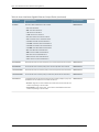
Filter statistics
Receive and Transmit statistics reported by the PIC's MAC address filter
extensive
subsystem. The filtering is done by the content-addressable memory (CAM)
on the PIC. The filter examines a packet's source and destination MAC addresses
to determine whether the packet should enter the system or be rejected.
•
Input packet count—Number of packets received from the MAC hardware
that the filter processed.
•
Input packet rejects—Number of packets that the filter rejected because of
either the source MAC address or the destination MAC address.
•
Input DA rejects—Number of packets that the filter rejected because the
destination MAC address of the packet is not on the accept list. It is normal
for this value to increment. When it increments very quickly and no traffic is
entering the routing device from the far-end system, either there is a bad ARP
entry on the far-end system, or multicast routing is not on and the far-end
system is sending many multicast packets to the local routing device (which
the routing device is rejecting).
•
Input SA rejects—Number of packets that the filter rejected because the
source MAC address of the packet is not on the accept list. The value in this
field should increment only if source MAC address filtering has been enabled.
If filtering is enabled, if the value increments quickly, and if the system is not
receiving traffic that it should from the far-end system, it means that the
user-configured source MAC addresses for this interface are incorrect.
•
Output packet count—Number of packets that the filter has given to the MAC
hardware.
•
Output packet pad count—Number of packets the filter padded to the
minimum Ethernet size (60 bytes) before giving the packet to the MAC
hardware. Usually, padding is done only on small ARP packets, but some very
small IP packets can also require padding. If this value increments rapidly,
either the system is trying to find an ARP entry for a far-end system that does
not exist or it is misconfigured.
•
Output packet error count—Number of packets with an indicated error that
the filter was given to transmit. These packets are usually aged packets or
are the result of a bandwidth problem on the FPC hardware. On a normal
system, the value of this field should not increment.
•
CAM destination filters, CAM source filters—Number of entries in the CAM
dedicated to destination and source MAC address filters. There can only be
up to 64 source entries. If source filtering is disabled, which is the default, the
values for these fields should be 0.
PMA PHY
(10-Gigabit Ethernet interfaces, WAN PHY mode) SONET error information:
•
Seconds—Number of seconds the defect has been active.
•
Count—Number of times that the defect has gone from inactive to active.
•
State—State of the error. Any state other than OK indicates a problem.
extensive
Subfields are:
•
PHY Lock—Phase-locked loop
•
PHY Light—Loss of optical signal
Copyright © 2013, Juniper Networks, Inc.
41
Static ARP Table Entries Feature Guide for Routing Devices
Table 3: show interfaces Fast Ethernet Output Fields (continued)
Field Name
Field Description
Level of Output
WIS section
(10-Gigabit Ethernet interfaces, WAN PHY mode) SONET error information:
extensive
•
Seconds—Number of seconds the defect has been active.
•
Count—Number of times that the defect has gone from inactive to active.
•
State—State of the error. Any state other than OK indicates a problem.
Subfields are:
WIS line
•
BIP-B1—Bit interleaved parity for SONET section overhead
•
SEF—Severely errored framing
•
LOL—Loss of light
•
LOF—Loss of frame
•
ES-S—Errored seconds (section)
•
SES-S—Severely errored seconds (section)
•
SEFS-S—Severely errored framing seconds (section)
(10-Gigabit Ethernet interfaces, WAN PHY mode) Active alarms and defects,
plus counts of specific SONET errors with detailed information.
•
Seconds—Number of seconds the defect has been active.
•
Count—Number of times that the defect has gone from inactive to active.
•
State—State of the error. State other than OK indicates a problem.
extensive
Subfields are:
42
•
BIP-B2—Bit interleaved parity for SONET line overhead
•
REI-L—Remote error indication (near-end line)
•
RDI-L—Remote defect indication (near-end line)
•
AIS-L—Alarm indication signal (near-end line)
•
BERR-SF—Bit error rate fault (signal failure)
•
BERR-SD—Bit error rate defect (signal degradation)
•
ES-L—Errored seconds (near-end line)
•
SES-L—Severely errored seconds (near-end line)
•
UAS-L—Unavailable seconds (near-end line)
•
ES-LFE—Errored seconds (far-end line)
•
SES-LFE—Severely errored seconds (far-end line)
•
UAS-LFE—Unavailable seconds (far-end line)
Copyright © 2013, Juniper Networks, Inc.
Chapter 5: Monitoring Commands
Table 3: show interfaces Fast Ethernet Output Fields (continued)
Field Name
Field Description
Level of Output
WIS path
(10-Gigabit Ethernet interfaces, WAN PHY mode) Active alarms and defects,
plus counts of specific SONET errors with detailed information.
extensive
•
Seconds—Number of seconds the defect has been active.
•
Count—Number of times that the defect has gone from inactive to active.
•
State—State of the error. Any state other than OK indicates a problem.
Subfields are:
•
BIP-B3—Bit interleaved parity for SONET section overhead
•
REI-P—Remote error indication
•
LOP-P—Loss of pointer (path)
•
AIS-P—Path alarm indication signal
•
RDI-P—Path remote defect indication
•
UNEQ-P—Path unequipped
•
PLM-P—Path payload (signal) label mismatch
•
ES-P—Errored seconds (near-end STS path)
•
SES-P—Severely errored seconds (near-end STS path)
•
UAS-P—Unavailable seconds (near-end STS path)
•
SES-PFE—Severely errored seconds (far-end STS path)
•
UAS-PFE—Unavailable seconds (far-end STS path)
Copyright © 2013, Juniper Networks, Inc.
43
Static ARP Table Entries Feature Guide for Routing Devices
Table 3: show interfaces Fast Ethernet Output Fields (continued)
Field Name
Field Description
Level of Output
Autonegotiation
information
Information about link autonegotiation.
extensive
•
Negotiation status:
•
Incomplete—Ethernet interface has the speed or link mode configured.
•
No autonegotiation—Remote Ethernet interface has the speed or link mode
configured, or does not perform autonegotiation.
•
Complete—Ethernet interface is connected to a device that performs
autonegotiation and the autonegotiation process is successful.
•
Link partner status—OK when Ethernet interface is connected to a device that
performs autonegotiation and the autonegotiation process is successful.
•
Link partner:
•
Link mode—Depending on the capability of the attached Ethernet device,
either Full-duplex or Half-duplex.
•
Flow control—Types of flow control supported by the remote Ethernet
device. For Fast Ethernet interfaces, the type is None. For Gigabit Ethernet
interfaces, types are Symmetric (link partner supports PAUSE on receive
and transmit), Asymmetric (link partner supports PAUSE on transmit), and
Symmetric/Asymmetric (link partner supports both PAUSE on receive and
transmit or only PAUSE receive).
•
Remote fault—Remote fault information from the link partner—Failure
indicates a receive link error. OK indicates that the link partner is receiving.
Negotiation error indicates a negotiation error. Offline indicates that the
link partner is going offline.
•
Local resolution—Information from the link partner:
•
Flow control—Types of flow control supported by the remote Ethernet
device. For Gigabit Ethernet interfaces, types are Symmetric (link partner
supports PAUSE on receive and transmit), Asymmetric (link partner supports
PAUSE on transmit), and Symmetric/Asymmetric (link partner supports
both PAUSE on receive and transmit or only PAUSE receive).
•
Remote fault—Remote fault information. Link OK (no error detected on
receive), Offline (local interface is offline), and Link Failure (link error
detected on receive).
Received path
trace, Transmitted
path trace
(10-Gigabit Ethernet interfaces, WAN PHY mode) SONET/SDH interfaces allow
path trace bytes to be sent inband across the SONET/SDH link. Juniper Networks
and other routing device manufacturers use these bytes to help diagnose
misconfigurations and network errors by setting the transmitted path trace
message so that it contains the system hostname and name of the physical
interface. The received path trace value is the message received from the routing
device at the other end of the fiber. The transmitted path trace value is the
message that this routing device transmits.
extensive
Packet Forwarding
Engine
configuration
Information about the configuration of the Packet Forwarding Engine:
extensive
44
•
Destination slot—FPC slot number.
Copyright © 2013, Juniper Networks, Inc.
Chapter 5: Monitoring Commands
Table 3: show interfaces Fast Ethernet Output Fields (continued)
Field Name
Field Description
Level of Output
CoS information
Information about the CoS queue for the physical interface.
extensive
•
CoS transmit queue—Queue number and its associated user-configured
forwarding class name.
•
Bandwidth %—Percentage of bandwidth allocated to the queue.
•
Bandwidth bps—Bandwidth allocated to the queue (in bps).
•
Buffer %—Percentage of buffer space allocated to the queue.
•
Buffer usec—Amount of buffer space allocated to the queue, in microseconds.
This value is nonzero only if the buffer size is configured in terms of time.
•
Priority—Queue priority: low or high.
•
Limit—Displayed if rate limiting is configured for the queue. Possible values
are none and exact. If exact is configured, the queue transmits only up to the
configured bandwidth, even if excess bandwidth is available. If none is
configured, the queue transmits beyond the configured bandwidth if
bandwidth is available.
Logical Interface
Logical interface
Name of the logical interface.
All levels
Index
Index number of the logical interface, which reflects its initialization sequence.
detail extensive none
SNMP ifIndex
SNMP interface index number for the logical interface.
detail extensive none
Generation
Unique number for use by Juniper Networks technical support only.
detail extensive
Flags
Information about the logical interface. Possible values are described in the
“Logical Interface Flags” section under Common Output Fields Description.
All levels
VLAN-Tag
Rewrite profile applied to incoming or outgoing frames on the outer (Out) VLAN
tag or for both the outer and inner (In) VLAN tags.
brief detail extensive
•
push—An outer VLAN tag is pushed in front of the existing VLAN tag.
•
pop—The outer VLAN tag of the incoming frame is removed.
•
swap—The outer VLAN tag of the incoming frame is overwritten with the user
none
specified VLAN tag information.
•
push—An outer VLAN tag is pushed in front of the existing VLAN tag.
•
push-push—Two VLAN tags are pushed in from the incoming frame.
•
swap-push—The outer VLAN tag of the incoming frame is replaced by a
user-specified VLAN tag value. A user-specified outer VLAN tag is pushed in
front. The outer tag becomes an inner tag in the final frame.
•
swap-swap—Both the inner and the outer VLAN tags of the incoming frame
are replaced by the user specified VLAN tag value.
•
pop-swap—The outer VLAN tag of the incoming frame is removed, and the
inner VLAN tag of the incoming frame is replaced by the user-specified VLAN
tag value. The inner tag becomes the outer tag in the final frame.
•
pop-pop—Both the outer and inner VLAN tags of the incoming frame are
removed.
Copyright © 2013, Juniper Networks, Inc.
45
Static ARP Table Entries Feature Guide for Routing Devices
Table 3: show interfaces Fast Ethernet Output Fields (continued)
Field Name
Field Description
Level of Output
Demux:
IP demultiplexing (demux) value that appears if this interface is used as the
demux underlying interface. The output is one of the following:
detail extensive none
•
Source Family Inet
•
Destination Family Inet
Encapsulation
Encapsulation on the logical interface.
All levels
Protocol
Protocol family. Possible values are described in the “Protocol Field” section
under Common Output Fields Description.
detail extensive none
MTU
Maximum transmission unit size on the logical interface.
detail extensive none
Maximum labels
Maximum number of MPLS labels configured for the MPLS protocol family on
the logical interface.
detail extensive none
Traffic statistics
Number and rate of bytes and packets received and transmitted on the specified
interface set.
detail extensive
•
Input bytes, Output bytes—Number of bytes received and transmitted on the
interface set
•
Input packets, Output packets—Number of packets received and transmitted
on the interface set.
IPv6 transit
statistics
Number of IPv6 transit bytes and packets received and transmitted on the
logical interface if IPv6 statistics tracking is enabled.
extensive
Local statistics
Number and rate of bytes and packets destined to the routing device.
extensive
Transit statistics
Number and rate of bytes and packets transiting the switch.
extensive
NOTE: For Gigabit Ethernet intelligent queuing 2 (IQ2) interfaces, the logical
interface egress statistics might not accurately reflect the traffic on the wire
when output shaping is applied. Traffic management output shaping might
drop packets after they are tallied by the Output bytes and Output packets
interface counters. However, correct values display for both of these egress
statistics when per-unit scheduling is enabled for the Gigabit Ethernet IQ2
physical interface, or when a single logical interface is actively using a shared
scheduler.
Generation
Unique number for use by Juniper Networks technical support only.
detail extensive
Route Table
Route table in which the logical interface address is located. For example, 0
refers to the routing table inet.0.
detail extensive none
Flags
Information about protocol family flags. Possible values are described in the
“Family Flags” section under Common Output Fields Description.
detail extensive
Donor interface
(Unnumbered Ethernet) Interface from which an unnumbered Ethernet interface
borrows an IPv4 address.
detail extensive none
46
Copyright © 2013, Juniper Networks, Inc.
Chapter 5: Monitoring Commands
Table 3: show interfaces Fast Ethernet Output Fields (continued)
Field Name
Field Description
Level of Output
Preferred source
address
(Unnumbered Ethernet) Secondary IPv4 address of the donor loopback interface
that acts as the preferred source address for the unnumbered Ethernet interface.
detail extensive none
Input Filters
Names of any input filters applied to this interface. If you specify a precedence
value for any filter in a dynamic profile, filter precedence values appear in
parenthesis next to all interfaces.
detail extensive
Output Filters
Names of any output filters applied to this interface. If you specify a precedence
value for any filter in a dynamic profile, filter precedence values appear in
parenthesis next to all interfaces.
detail extensive
Mac-Validate
Failures
Number of MAC address validation failures for packets and bytes. This field is
displayed when MAC address validation is enabled for the logical interface.
detail extensive none
Addresses, Flags
Information about the address flags. Possible values are described in the
“Addresses Flags” section under Common Output Fields Description.
detail extensive none
protocol-family
Protocol family configured on the logical interface. If the protocol is inet, the IP
address of the interface is also displayed.
brief
Flags
Information about address flag (possible values are described in the “Addresses
Flags” section under Common Output Fields Description.
detail extensive none
Destination
IP address of the remote side of the connection.
detail extensive none
Local
IP address of the logical interface.
detail extensive none
Broadcast
Broadcast address of the logical interlace.
detail extensive none
Generation
Unique number for use by Juniper Networks technical support only.
detail extensive
Sample Output
show interfaces (Fast Ethernet)
user@host> show interfaces fe-0/0/0
Physical interface: fe-0/0/0, Enabled, Physical link is Up
Interface index: 128, SNMP ifIndex: 22
Link-level type: Ethernet, MTU: 1514, Speed: 100mbps, Loopback: Disabled,
Source filtering: Disabled, Flow control: Enabled
Device flags
: Present Running
Interface flags: SNMP-Traps Internal: 0x4000
CoS queues
: 4 supported, 4 maximum usable queues
Current address: 00:05:85:02:38:00, Hardware address: 00:05:85:02:38:00
Last flapped
: 2006-01-20 14:50:58 PST (2w4d 00:44 ago)
Input rate
: 0 bps (0 pps)
Output rate
: 0 bps (0 pps)
Active alarms : None
Active defects : None
Logical interface fe-0/0/0.0 (Index 66) (SNMP ifIndex 198)
Flags: SNMP-Traps Encapsulation: ENET2
Copyright © 2013, Juniper Networks, Inc.
47
Static ARP Table Entries Feature Guide for Routing Devices
Protocol inet, MTU: 1500
Flags: None
Addresses, Flags: Is-Preferred Is-Primary
Destination: 10.10.10/24, Local: 10.10.10.1, Broadcast: 10.10.10.255
show interfaces brief (Fast Ethernet)
user@host> show interfaces fe-0/0/0 brief
Physical interface: fe-0/0/0, Enabled, Physical link is Up
Link-level type: Ethernet, MTU: 1514, Speed: 100mbps, Loopback: Disabled,
Source filtering: Disabled, Flow control: Enabled
Device flags
: Present Running
Interface flags: SNMP-Traps Internal: 0x4000
Logical interface fe-0/0/0.0
Flags: SNMP-Traps Encapsulation: ENET2
inet 10.10.10.1/24
show interfaces detail (Fast Ethernet)
user@host> show interfaces fe-0/0/0 detail
Physical interface: fe-0/0/0, Enabled, Physical link is Up
Interface index: 128, SNMP ifIndex: 22, Generation: 5391
Link-level type: Ethernet, MTU: 1514, Speed: 100mbps, Loopback: Disabled,
Source filtering: Disabled, Flow control: Enabled
Device flags
: Present Running
Interface flags: SNMP-Traps Internal: 0x4000
CoS queues
: 4 supported, 4 maximum usable queues
Hold-times
: Up 0 ms, Down 0 ms
Current address: 00:05:85:02:38:00, Hardware address: 00:05:85:02:38:00
Last flapped
: 2006-01-20 14:50:58 PST (2w4d 00:45 ago)
Statistics last cleared: Never
Traffic statistics:
Input bytes :
0
0 bps
Output bytes :
42
0 bps
Input packets:
0
0 pps
Output packets:
1
0 pps
Active alarms : None
Active defects : None
Logical interface fe-0/0/0.0 (Index 66) (SNMP ifIndex 198) (Generation 67)
Flags: SNMP-Traps Encapsulation: ENET2
Protocol inet, MTU: 1500, Generation: 105, Route table: 0
Flags: Is-Primary, Mac-Validate-Strict
Mac-Validate Failures: Packets: 0, Bytes: 0
Addresses, Flags: Is-Preferred Is-Primary
Destination: 10.10.10/24, Local: 10.10.10.1, Broadcast: 10.10.10.255,
Generation: 136
show interfaces extensive (Fast Ethernet)
user@host> show interfaces fe-0/0/0 extensive
Physical interface: fe-0/0/0, Enabled, Physical link is Up
Interface index: 128, SNMP ifIndex: 22, Generation: 5391
Link-level type: Ethernet, MTU: 1514, Link-mode: Full-duplex, Speed:
100mbps, Loopback: Disabled,
Source filtering: Disabled, Flow control: Enabled
Device flags
: Present Running
Interface flags: SNMP-Traps Internal: 0x4000
CoS queues
: 4 supported, 4 maximum usable queues
Hold-times
: Up 0 ms, Down 0 ms
Current address: 00:05:85:02:38:00, Hardware address: 00:05:85:02:38:00
Last flapped
: 2006-01-20 14:50:58 PST (2w4d 00:46 ago)
Statistics last cleared: Never
48
Copyright © 2013, Juniper Networks, Inc.
Chapter 5: Monitoring Commands
Traffic statistics:
Input bytes :
0
0 bps
Output bytes :
42
0 bps
Input packets:
0
0 pps
Output packets:
1
0 pps
Input errors:
Errors: 0, Drops: 0, Framing errors: 0, Runts: 0, Policed discards: 0,
L3 incompletes: 0, L2 channel errors: 0, L2 mismatch timeouts: 0,
FIFO errors: 0, Resource errors: 0
Output errors:
Carrier transitions: 3, Errors: 0, Drops: 0, Collisions: 0, Aged packets: 0,
FIFO errors: 0, HS link CRC errors: 0, MTU errors: 0, Resource errors: 0
Active alarms : None
Active defects : None
MAC statistics:
Receive
Transmit
Total octets
0
64
Total packets
0
1
Unicast packets
0
0
Broadcast packets
0
1
Multicast packets
0
0
CRC/Align errors
0
0
FIFO errors
0
0
MAC control frames
0
0
MAC pause frames
0
0
Oversized frames
0
Jabber frames
0
Fragment frames
0
VLAN tagged frames
0
Code violations
0
Filter statistics:
Input packet count
0
Input packet rejects
0
Input DA rejects
0
Input SA rejects
0
Output packet count
1
Output packet pad count
0
Output packet error count
0
CAM destination filters: 1, CAM source filters: 0
Autonegotiation information:
Negotiation status: Complete
Link partner:
Link partner: Full-duplex, Flow control: None, Remote fault: Ok
Local resolution:
Packet Forwarding Engine configuration:
Destination slot: 0
CoS information:
Bandwidth
Buffer Priority
Limit
%
bps
%
usec
0 best-effort
95
950000000 95
0
low
none
3 network-control
5
50000000
5
0
low
none
Logical interface fe-0/0/0.0 (Index 66) (SNMP ifIndex 198) (Generation 67)
Flags: SNMP-Traps Encapsulation: ENET2
Protocol inet, MTU: 1500, Generation: 105, Route table: 0
Flags: None
Addresses, Flags: Is-Preferred Is-Primary
Destination: 10.10.10/24, Local: 10.10.10.1, Broadcast: 10.10.10.255,
Generation: 136
Copyright © 2013, Juniper Networks, Inc.
49
Static ARP Table Entries Feature Guide for Routing Devices
show interfaces (Gigabit Ethernet)
Syntax
Release Information
Description
Options
show interfaces ge-fpc/pic/port
<brief | detail | extensive | terse>
<descriptions>
<media>
<snmp-index snmp-index>
<statistics>
Command introduced before Junos OS Release 7.4.
(M Series, T Series, and MX Series routers and EX Series switches only) Display status
information about the specified Gigabit Ethernet interface.
ge-fpc/pic/port—Display standard information about the specified Gigabit Ethernet
interface.
brief | detail | extensive | terse—(Optional) Display the specified level of output.
descriptions—(Optional) Display interface description strings.
media—(Optional) Display media-specific information about network interfaces.
snmp-index snmp-index—(Optional) Display information for the specified SNMP index
of the interface.
statistics—(Optional) Display static interface statistics.
Additional Information
Required Privilege
Level
Related
Documentation
List of Sample Output
Output Fields
50
In a logical system, this command displays information only about the logical interfaces
and not about the physical interfaces.
view
•
Verifying and Managing Agent Circuit Identifier-Based Dynamic VLAN Configuration
show interfaces (Gigabit Ethernet) on page 65
show interfaces (Gigabit Ethernet on MX Series Routers) on page 65
show interfaces extensive (Gigabit Ethernet on MX Series Routers showing interface
transmit statistics configuration) on page 66
show interfaces brief (Gigabit Ethernet) on page 66
show interfaces detail (Gigabit Ethernet) on page 66
show interfaces extensive (Gigabit Ethernet IQ2) on page 68
show interfaces (Gigabit Ethernet Unnumbered Interface) on page 71
show interfaces (ACI Interface Set Configured) on page 71
Table 4 on page 51 describes the output fields for the show interfaces (Gigabit Ethernet)
command. Output fields are listed in the approximate order in which they appear. For
Gigabit Ethernet IQ and IQE PICs, the traffic and MAC statistics vary by interface type.
For more information, see Table 5 on page 64.
Copyright © 2013, Juniper Networks, Inc.
Chapter 5: Monitoring Commands
Table 4: show interfaces Gigabit Ethernet Output Fields
Field Name
Field Description
Level of Output
Physical interface
Name of the physical interface.
All levels
Enabled
State of the interface. Possible values are described in the “Enabled Field”
section under Common Output Fields Description.
All levels
Interface index
Index number of the physical interface, which reflects its initialization sequence.
detail extensive none
SNMP ifIndex
SNMP index number for the physical interface.
detail extensive none
Generation
Unique number for use by Juniper Networks technical support only.
detail extensive
Link-level type
Encapsulation being used on the physical interface.
All levels
MTU
Maximum transmission unit size on the physical interface.
All levels
Speed
Speed at which the interface is running.
All levels
Loopback
Loopback status: Enabled or Disabled. If loopback is enabled, type of loopback:
Local or Remote.
All levels
Source filtering
Source filtering status: Enabled or Disabled.
All levels
LAN-PHY mode
10-Gigabit Ethernet interface operating in Local Area Network Physical Layer
Device (LAN PHY) mode. LAN PHY allows 10-Gigabit Ethernet wide area links
to use existing Ethernet applications.
All levels
WAN-PHY mode
10-Gigabit Ethernet interface operating in Wide Area Network Physical Layer
Device (WAN PHY) mode. WAN PHY allows 10-Gigabit Ethernet wide area links
to use fiber-optic cables and other devices intended for SONET/SDH.
All levels
Unidirectional
Unidirectional link mode status for 10-Gigabit Ethernet interface: Enabled or
Disabled for parent interface; Rx-only or Tx-only for child interfaces.
All levels
Flow control
Flow control status: Enabled or Disabled.
All levels
Auto-negotiation
(Gigabit Ethernet interfaces) Autonegotiation status: Enabled or Disabled.
All levels
Remote-fault
(Gigabit Ethernet interfaces) Remote fault status:
All levels
Physical Interface
•
Online—Autonegotiation is manually configured as online.
•
Offline—Autonegotiation is manually configured as offline.
Device flags
Information about the physical device. Possible values are described in the
“Device Flags” section under Common Output Fields Description.
All levels
Interface flags
Information about the interface. Possible values are described in the “Interface
Flags” section under Common Output Fields Description.
All levels
Copyright © 2013, Juniper Networks, Inc.
51
Static ARP Table Entries Feature Guide for Routing Devices
Table 4: show interfaces Gigabit Ethernet Output Fields (continued)
Field Name
Field Description
Level of Output
Link flags
Information about the link. Possible values are described in the “Links Flags”
section under Common Output Fields Description.
All levels
Wavelength
(10-Gigabit Ethernet dense wavelength-division multiplexing [DWDM]
interfaces) Displays the configured wavelength, in nanometers (nm).
All levels
Frequency
(10-Gigabit Ethernet DWDM interfaces only) Displays the frequency associated
with the configured wavelength, in terahertz (THz).
All levels
CoS queues
Number of CoS queues configured.
detail extensive none
Schedulers
(Gigabit Ethernet intelligent queuing 2 [IQ2] interfaces only) Number of CoS
schedulers configured.
extensive
Hold-times
Current interface hold-time up and hold-time down, in milliseconds (ms).
detail extensive
Current address
Configured MAC address.
detail extensive none
Hardware address
Hardware MAC address.
detail extensive none
Last flapped
Date, time, and how long ago the interface went from down to up. The format
is Last flapped: year-month-day hour:minute:second:timezone (hour:minute:second
ago). For example, Last flapped: 2002-04-26 10:52:40 PDT (04:33:20 ago).
detail extensive none
Input Rate
Input rate in bits per second (bps) and packets per second (pps). The value in
this field also includes the Layer 2 overhead bytes for ingress traffic on Ethernet
interfaces if you enable accounting of Layer 2 overhead at the PIC level or the
logical interface level.
None
Output Rate
Output rate in bps and pps. The value in this field also includes the Layer 2
overhead bytes for egress traffic on Ethernet interfaces if you enable accounting
of Layer 2 overhead at the PIC level or the logical interface level.
None
Statistics last
cleared
Time when the statistics for the interface were last set to zero.
detail extensive
Egress accounting
overhead
Layer 2 overhead in bytes that is accounted in the interface statistics for egress
traffic.
detail extensive
Ingress accounting
overhead
Layer 2 overhead in bytes that is accounted in the interface statistics for ingress
traffic.
detail extensive
52
Copyright © 2013, Juniper Networks, Inc.
Chapter 5: Monitoring Commands
Table 4: show interfaces Gigabit Ethernet Output Fields (continued)
Field Name
Field Description
Level of Output
Traffic statistics
Number and rate of bytes and packets received and transmitted on the physical
interface.
detail extensive
•
Input bytes—Number of bytes received on the interface. The value in this field
also includes the Layer 2 overhead bytes for ingress traffic on Ethernet
interfaces if you enable accounting of Layer 2 overhead at the PIC level or
the logical interface level.
•
Output bytes—Number of bytes transmitted on the interface. The value in
this field also includes the Layer 2 overhead bytes for egress traffic on Ethernet
interfaces if you enable accounting of Layer 2 overhead at the PIC level or
the logical interface level.
•
Input packets—Number of packets received on the interface.
•
Output packets—Number of packets transmitted on the interface.
Gigabit Ethernet and 10-Gigabit Ethernet IQ PICs count the overhead and CRC
bytes.
For Gigabit Ethernet IQ PICs, the input byte counts vary by interface type. For
more information, see Table 31 under the show interfaces (10-Gigabit Ethernet)
command.
Input errors
Input errors on the interface. The following paragraphs explain the counters
whose meaning might not be obvious:
•
Errors—Sum of the incoming frame aborts and FCS errors.
•
Drops—Number of packets dropped by the input queue of the I/O Manager
extensive
ASIC. If the interface is saturated, this number increments once for every
packet that is dropped by the ASIC's RED mechanism.
•
Framing errors—Number of packets received with an invalid frame checksum
(FCS).
•
Runts—Number of frames received that are smaller than the runt threshold.
•
Policed discards—Number of frames that the incoming packet match code
discarded because they were not recognized or not of interest. Usually, this
field reports protocols that Junos OS does not handle.
•
L3 incompletes—Number of incoming packets discarded because they failed
Layer 3 (usually IPv4) sanity checks of the header. For example, a frame with
less than 20 bytes of available IP header is discarded. L3 incomplete errors
can be ignored by configuring the ignore-l3-incompletes statement.
•
L2 channel errors—Number of times the software did not find a valid logical
interface for an incoming frame.
•
L2 mismatch timeouts—Number of malformed or short packets that caused
the incoming packet handler to discard the frame as unreadable.
•
FIFO errors—Number of FIFO errors in the receive direction that are reported
by the ASIC on the PIC. If this value is ever nonzero, the PIC is probably
malfunctioning.
•
Resource errors—Sum of transmit drops.
Copyright © 2013, Juniper Networks, Inc.
53
Static ARP Table Entries Feature Guide for Routing Devices
Table 4: show interfaces Gigabit Ethernet Output Fields (continued)
Field Name
Field Description
Level of Output
Output errors
Output errors on the interface. The following paragraphs explain the counters
whose meaning might not be obvious:
extensive
•
Carrier transitions—Number of times the interface has gone from down to up.
This number does not normally increment quickly, increasing only when the
cable is unplugged, the far-end system is powered down and then up, or
another problem occurs. If the number of carrier transitions increments quickly
(perhaps once every 10 seconds), the cable, the far-end system, or the PIC
or PIM is malfunctioning.
•
Errors—Sum of the outgoing frame aborts and FCS errors.
•
Drops—Number of packets dropped by the output queue of the I/O Manager
ASIC. If the interface is saturated, this number increments once for every
packet that is dropped by the ASIC's RED mechanism.
NOTE: Due to accounting space limitations on certain Type 3 FPCs (which are
supported in M320 and T640 routers), the Drops field does not always use the
correct value for queue 6 or queue 7 for interfaces on 10-port 1-Gigabit Ethernet
PICs.
•
Collisions—Number of Ethernet collisions. The Gigabit Ethernet PIC supports
only full-duplex operation, so for Gigabit Ethernet PICs, this number should
always remain 0. If it is nonzero, there is a software bug.
•
Aged packets—Number of packets that remained in shared packet SDRAM
so long that the system automatically purged them. The value in this field
should never increment. If it does, it is most likely a software bug or possibly
malfunctioning hardware.
•
FIFO errors—Number of FIFO errors in the send direction as reported by the
ASIC on the PIC. If this value is ever nonzero, the PIC is probably
malfunctioning.
•
HS link CRC errors—Number of errors on the high-speed links between the
ASICs responsible for handling the router interfaces.
•
MTU errors—Number of packets whose size exceeded the MTU of the interface.
•
Resource errors—Sum of transmit drops.
Egress queues
Total number of egress queues supported on the specified interface.
detail extensive
Queue counters
(Egress)
CoS queue number and its associated user-configured forwarding class name.
detail extensive
•
Queued packets—Number of queued packets.
•
Transmitted packets—Number of transmitted packets.
•
Dropped packets—Number of packets dropped by the ASIC's RED mechanism.
NOTE: Due to accounting space limitations on certain Type 3 FPCs (which are
supported in M320 and T640 routers), the Dropped packets field does not always
display the correct value for queue 6 or queue 7 for interfaces on 10-port 1-Gigabit
Ethernet PICs.
Ingress queues
54
Total number of ingress queues supported on the specified interface. Displayed
on IQ2 interfaces.
extensive
Copyright © 2013, Juniper Networks, Inc.
Chapter 5: Monitoring Commands
Table 4: show interfaces Gigabit Ethernet Output Fields (continued)
Field Name
Field Description
Level of Output
Queue counters
(Ingress)
CoS queue number and its associated user-configured forwarding class name.
Displayed on IQ2 interfaces.
extensive
Active alarms and
Active defects
•
Queued packets—Number of queued packets.
•
Transmitted packets—Number of transmitted packets.
•
Dropped packets—Number of packets dropped by the ASIC's RED mechanism.
Ethernet-specific defects that can prevent the interface from passing packets.
When a defect persists for a certain amount of time, it is promoted to an alarm.
Based on the router configuration, an alarm can ring the red or yellow alarm
bell on the router, or turn on the red or yellow alarm LED on the craft interface.
These fields can contain the value None or Link.
•
None—There are no active defects or alarms.
•
Link—Interface has lost its link state, which usually means that the cable is
detail extensive none
unplugged, the far-end system has been turned off, or the PIC is
malfunctioning.
Interface transmit
statistics
(On MX Series devices) Status of the interface-transmit-statistics configuration:
Enabled or Disabled.
•
detail extensive
Enabled—When the interface-transmit-statistics statement is included in the
configuration. If this is configured, the interface statistics show the actual
transmitted load on the interface.
•
Disabled—When the interface-transmit-statistics statement is not included
in the configuration. If this is not configured, the interface statistics show the
offered load on the interface.
OTN FEC statistics
The forward error correction (FEC) counters provide the following statistics:
•
Corrected Errors—The count of corrected errors in the last second.
•
Corrected Error Ratio—The corrected error ratio in the last 25 seconds. For
detail extensive
example, 1e-7 is 1 error per 10 million bits.
PCS statistics
(10-Gigabit Ethernet interfaces) Displays Physical Coding Sublayer (PCS) fault
conditions from the WAN PHY or the LAN PHY device.
•
detail extensive
Bit errors—High bit error rate. Indicates the number of bit errors when the PCS
receiver is operating in normal mode.
•
Errored blocks—Loss of block lock. The number of errored blocks when the
PCS receiver is operating in normal mode.
Copyright © 2013, Juniper Networks, Inc.
55
Static ARP Table Entries Feature Guide for Routing Devices
Table 4: show interfaces Gigabit Ethernet Output Fields (continued)
Field Name
Field Description
Level of Output
MAC statistics
Receive and Transmit statistics reported by the PIC's MAC subsystem, including
extensive
the following:
•
Total octets and total packets—Total number of octets and packets. For
Gigabit Ethernet IQ PICs, the received octets count varies by interface type.
For more information, see Table 31 under the show interfaces (10-Gigabit
Ethernet) command.
•
Unicast packets, Broadcast packets, and Multicast packets—Number of unicast,
broadcast, and multicast packets.
•
CRC/Align errors—Total number of packets received that had a length
(excluding framing bits, but including FCS octets) of between 64 and 1518
octets, inclusive, and had either a bad FCS with an integral number of octets
(FCS Error) or a bad FCS with a nonintegral number of octets (Alignment
Error).
•
FIFO error—Number of FIFO errors that are reported by the ASIC on the PIC.
If this value is ever nonzero, the PIC or a cable is probably malfunctioning.
•
MAC control frames—Number of MAC control frames.
•
MAC pause frames—Number of MAC control frames with pause operational
code.
•
Oversized frames—There are two possible conditions regarding the number
of oversized frames:
•
•
Packet length exceeds 1518 octets, or
•
Packet length exceeds MRU
Jabber frames—Number of frames that were longer than 1518 octets (excluding
framing bits, but including FCS octets), and had either an FCS error or an
alignment error. This definition of jabber is different from the definition in
IEEE-802.3 section 8.2.1.5 (10BASE5) and section 10.3.1.4 (10BASE2). These
documents define jabber as the condition in which any packet exceeds 20
ms. The allowed range to detect jabber is from 20 ms to 150 ms.
•
Fragment frames—Total number of packets that were less than 64 octets in
length (excluding framing bits, but including FCS octets) and had either an
FCS error or an alignment error. Fragment frames normally increment because
both runts (which are normal occurrences caused by collisions) and noise
hits are counted.
•
VLAN tagged frames—Number of frames that are VLAN tagged. The system
uses the TPID of 0x8100 in the frame to determine whether a frame is tagged
or not.
NOTE: The 20-port Gigabit Ethernet MIC (MIC-3D-20GE-SFP) does not have
hardware counters for VLAN frames. Therefore, the VLAN tagged frames field
displays 0 when the show interfaces command is executed on a 20-port Gigabit
Ethernet MIC. In other words, the number of VLAN tagged frames cannot be
determined for the 20-port Gigabit Ethernet MIC.
•
Code violations—Number of times an event caused the PHY to indicate “Data
reception error” or “invalid data symbol error.”
OTN Received
Overhead Bytes
APS/PCC0: 0x02, APS/PCC1: 0x11, APS/PCC2: 0x47, APS/PCC3: 0x58 Payload
Type: 0x08
extensive
OTN Transmitted
Overhead Bytes
APS/PCC0: 0x00, APS/PCC1: 0x00, APS/PCC2: 0x00, APS/PCC3: 0x00
Payload Type: 0x08
extensive
56
Copyright © 2013, Juniper Networks, Inc.
Chapter 5: Monitoring Commands
Table 4: show interfaces Gigabit Ethernet Output Fields (continued)
Field Name
Field Description
Level of Output
Filter statistics
Receive and Transmit statistics reported by the PIC's MAC address filter
extensive
subsystem. The filtering is done by the content-addressable memory (CAM)
on the PIC. The filter examines a packet's source and destination MAC addresses
to determine whether the packet should enter the system or be rejected.
•
Input packet count—Number of packets received from the MAC hardware
that the filter processed.
•
Input packet rejects—Number of packets that the filter rejected because of
either the source MAC address or the destination MAC address.
•
Input DA rejects—Number of packets that the filter rejected because the
destination MAC address of the packet is not on the accept list. It is normal
for this value to increment. When it increments very quickly and no traffic is
entering the router from the far-end system, either there is a bad ARP entry
on the far-end system, or multicast routing is not on and the far-end system
is sending many multicast packets to the local router (which the router is
rejecting).
•
Input SA rejects—Number of packets that the filter rejected because the
source MAC address of the packet is not on the accept list. The value in this
field should increment only if source MAC address filtering has been enabled.
If filtering is enabled, if the value increments quickly, and if the system is not
receiving traffic that it should from the far-end system, it means that the
user-configured source MAC addresses for this interface are incorrect.
•
Output packet count—Number of packets that the filter has given to the MAC
hardware.
•
Output packet pad count—Number of packets the filter padded to the
minimum Ethernet size (60 bytes) before giving the packet to the MAC
hardware. Usually, padding is done only on small ARP packets, but some very
small IP packets can also require padding. If this value increments rapidly,
either the system is trying to find an ARP entry for a far-end system that does
not exist or it is misconfigured.
•
Output packet error count—Number of packets with an indicated error that
the filter was given to transmit. These packets are usually aged packets or
are the result of a bandwidth problem on the FPC hardware. On a normal
system, the value of this field should not increment.
•
CAM destination filters, CAM source filters—Number of entries in the CAM
dedicated to destination and source MAC address filters. There can only be
up to 64 source entries. If source filtering is disabled, which is the default, the
values for these fields should be 0.
PMA PHY
(10-Gigabit Ethernet interfaces, WAN PHY mode) SONET error information:
•
Seconds—Number of seconds the defect has been active.
•
Count—Number of times that the defect has gone from inactive to active.
•
State—State of the error. Any state other than OK indicates a problem.
extensive
Subfields are:
•
PHY Lock—Phase-locked loop
•
PHY Light—Loss of optical signal
Copyright © 2013, Juniper Networks, Inc.
57
Static ARP Table Entries Feature Guide for Routing Devices
Table 4: show interfaces Gigabit Ethernet Output Fields (continued)
Field Name
Field Description
Level of Output
WIS section
(10-Gigabit Ethernet interfaces, WAN PHY mode) SONET error information:
extensive
•
Seconds—Number of seconds the defect has been active.
•
Count—Number of times that the defect has gone from inactive to active.
•
State—State of the error. Any state other than OK indicates a problem.
Subfields are:
WIS line
•
BIP-B1—Bit interleaved parity for SONET section overhead
•
SEF—Severely errored framing
•
LOL—Loss of light
•
LOF—Loss of frame
•
ES-S—Errored seconds (section)
•
SES-S—Severely errored seconds (section)
•
SEFS-S—Severely errored framing seconds (section)
(10-Gigabit Ethernet interfaces, WAN PHY mode) Active alarms and defects,
plus counts of specific SONET errors with detailed information:
•
Seconds—Number of seconds the defect has been active.
•
Count—Number of times that the defect has gone from inactive to active.
•
State—State of the error. Any state other than OK indicates a problem.
extensive
Subfields are:
58
•
BIP-B2—Bit interleaved parity for SONET line overhead
•
REI-L—Remote error indication (near-end line)
•
RDI-L—Remote defect indication (near-end line)
•
AIS-L—Alarm indication signal (near-end line)
•
BERR-SF—Bit error rate fault (signal failure)
•
BERR-SD—Bit error rate defect (signal degradation)
•
ES-L—Errored seconds (near-end line)
•
SES-L—Severely errored seconds (near-end line)
•
UAS-L—Unavailable seconds (near-end line)
•
ES-LFE—Errored seconds (far-end line)
•
SES-LFE—Severely errored seconds (far-end line)
•
UAS-LFE—Unavailable seconds (far-end line)
Copyright © 2013, Juniper Networks, Inc.
Chapter 5: Monitoring Commands
Table 4: show interfaces Gigabit Ethernet Output Fields (continued)
Field Name
Field Description
Level of Output
WIS path
(10-Gigabit Ethernet interfaces, WAN PHY mode) Active alarms and defects,
plus counts of specific SONET errors with detailed information:
extensive
•
Seconds—Number of seconds the defect has been active.
•
Count—Number of times that the defect has gone from inactive to active.
•
State—State of the error. Any state other than OK indicates a problem.
Subfields are:
•
BIP-B3—Bit interleaved parity for SONET section overhead
•
REI-P—Remote error indication
•
LOP-P—Loss of pointer (path)
•
AIS-P—Path alarm indication signal
•
RDI-P—Path remote defect indication
•
UNEQ-P—Path unequipped
•
PLM-P—Path payload (signal) label mismatch
•
ES-P—Errored seconds (near-end STS path)
•
SES-P—Severely errored seconds (near-end STS path)
•
UAS-P—Unavailable seconds (near-end STS path)
•
SES-PFE—Severely errored seconds (far-end STS path)
•
UAS-PFE—Unavailable seconds (far-end STS path)
Copyright © 2013, Juniper Networks, Inc.
59
Static ARP Table Entries Feature Guide for Routing Devices
Table 4: show interfaces Gigabit Ethernet Output Fields (continued)
Field Name
Field Description
Level of Output
Autonegotiation
information
Information about link autonegotiation.
extensive
•
Negotiation status:
•
Incomplete—Ethernet interface has the speed or link mode configured.
•
No autonegotiation—Remote Ethernet interface has the speed or link mode
configured, or does not perform autonegotiation.
•
Complete—Ethernet interface is connected to a device that performs
autonegotiation and the autonegotiation process is successful.
•
Link partner status—OK when Ethernet interface is connected to a device that
performs autonegotiation and the autonegotiation process is successful.
•
Link partner—Information from the remote Ethernet device:
•
Link mode—Depending on the capability of the link partner, either
Full-duplex or Half-duplex.
•
Flow control—Types of flow control supported by the link partner. For
Gigabit Ethernet interfaces, types are Symmetric (link partner supports
PAUSE on receive and transmit), Asymmetric (link partner supports PAUSE
on transmit), Symmetric/Asymmetric (link partner supports PAUSE on
receive and transmit or only PAUSE on transmit), and None (link partner
does not support flow control).
•
Remote fault—Remote fault information from the link partner—Failure
indicates a receive link error. OK indicates that the link partner is receiving.
Negotiation error indicates a negotiation error. Offline indicates that the
link partner is going offline.
•
Local resolution—Information from the local Ethernet device:
•
Flow control—Types of flow control supported by the local device. For
Gigabit Ethernet interfaces, advertised capabilities are
Symmetric/Asymmetric (local device supports PAUSE on receive and
transmit or only PAUSE on receive) and None (local device does not support
flow control). Depending on the result of the negotiation with the link
partner, local resolution flow control type will display Symmetric (local
device supports PAUSE on receive and transmit), Asymmetric (local device
supports PAUSE on receive), and None (local device does not support flow
control).
•
Remote fault—Remote fault information. Link OK (no error detected on
receive), Offline (local interface is offline), and Link Failure (link error
detected on receive).
Received path
trace, Transmitted
path trace
(10-Gigabit Ethernet interfaces, WAN PHY mode) SONET/SDH interfaces allow
path trace bytes to be sent inband across the SONET/SDH link. Juniper Networks
and other router manufacturers use these bytes to help diagnose
misconfigurations and network errors by setting the transmitted path trace
message so that it contains the system hostname and name of the physical
interface. The received path trace value is the message received from the router
at the other end of the fiber. The transmitted path trace value is the message
that this router transmits.
extensive
Packet Forwarding
Engine
configuration
Information about the configuration of the Packet Forwarding Engine:
extensive
60
•
Destination slot—FPC slot number.
Copyright © 2013, Juniper Networks, Inc.
Chapter 5: Monitoring Commands
Table 4: show interfaces Gigabit Ethernet Output Fields (continued)
Field Name
Field Description
Level of Output
CoS information
Information about the CoS queue for the physical interface.
extensive
•
CoS transmit queue—Queue number and its associated user-configured
forwarding class name.
•
Bandwidth %—Percentage of bandwidth allocated to the queue.
•
Bandwidth bps—Bandwidth allocated to the queue (in bps).
•
Buffer %—Percentage of buffer space allocated to the queue.
•
Buffer usec—Amount of buffer space allocated to the queue, in microseconds.
This value is nonzero only if the buffer size is configured in terms of time.
•
Priority—Queue priority: low or high.
•
Limit—Displayed if rate limiting is configured for the queue. Possible values
are none and exact. If exact is configured, the queue transmits only up to the
configured bandwidth, even if excess bandwidth is available. If none is
configured, the queue transmits beyond the configured bandwidth if
bandwidth is available.
Logical Interface
Logical interface
Name of the logical interface.
All levels
Index
Index number of the logical interface, which reflects its initialization sequence.
detail extensive none
SNMP ifIndex
SNMP interface index number for the logical interface.
detail extensive none
Generation
Unique number for use by Juniper Networks technical support only.
detail extensive
Flags
Information about the logical interface. Possible values are described in the
“Logical Interface Flags” section under Common Output Fields Description.
All levels
Copyright © 2013, Juniper Networks, Inc.
61
Static ARP Table Entries Feature Guide for Routing Devices
Table 4: show interfaces Gigabit Ethernet Output Fields (continued)
Field Name
Field Description
Level of Output
VLAN-Tag
Rewrite profile applied to incoming or outgoing frames on the outer (Out) VLAN
tag or for both the outer and inner (In) VLAN tags.
brief detail extensive
•
push—An outer VLAN tag is pushed in front of the existing VLAN tag.
•
pop—The outer VLAN tag of the incoming frame is removed.
•
swap—The outer VLAN tag of the incoming frame is overwritten with the
none
user-specified VLAN tag information.
•
push—An outer VLAN tag is pushed in front of the existing VLAN tag.
•
push-push—Two VLAN tags are pushed in from the incoming frame.
•
swap-push—The outer VLAN tag of the incoming frame is replaced by a
user-specified VLAN tag value. A user-specified outer VLAN tag is pushed in
front. The outer tag becomes an inner tag in the final frame.
•
swap-swap—Both the inner and the outer VLAN tags of the incoming frame
are replaced by the user-specified VLAN tag value.
•
pop-swap—The outer VLAN tag of the incoming frame is removed, and the
inner VLAN tag of the incoming frame is replaced by the user-specified VLAN
tag value. The inner tag becomes the outer tag in the final frame.
•
pop-pop—Both the outer and inner VLAN tags of the incoming frame are
removed.
Demux
IP demultiplexing (demux) value that appears if this interface is used as the
demux underlying interface. The output is one of the following:
•
Source Family Inet
•
Destination Family Inet
detail extensive none
Encapsulation
Encapsulation on the logical interface.
All levels
ACI VLAN: Dynamic
Profile
Name of the dynamic profile that defines the agent circuit identifier (ACI)
interface set. If configured, the ACI interface set enables the underlying Ethernet
interface to create dynamic VLAN subscriber interfaces based on ACI
information.
brief detail extensive
Protocol
Protocol family. Possible values are described in the “Protocol Field” section
under Common Output Fields Description.
detail extensive none
MTU
Maximum transmission unit size on the logical interface.
detail extensive none
Dynamic Profile
(MX Series routers with Trio MPCs only) Name of the dynamic profile that was
used to create this interface configured with a Point-to-Point Protocol over
Ethernet (PPPoE) family.
detail extensive none
Service Name Table
(MX Series routers with Trio MPCs only) Name of the service name table for
the interface configured with a PPPoE family.
detail extensive none
Max Sessions
(MX Series routers with Trio MPCs only) Maximum number of PPPoE logical
interfaces that can be activated on the underlying interface.
detail extensive none
62
none
Copyright © 2013, Juniper Networks, Inc.
Chapter 5: Monitoring Commands
Table 4: show interfaces Gigabit Ethernet Output Fields (continued)
Field Name
Field Description
Level of Output
Duplicate
Protection
(MX Series routers with Trio MPCs only) State of PPPoE duplicate protection:
On or Off. When duplicate protection is configured for the underlying interface,
a dynamic PPPoE logical interface cannot be activated when an existing active
logical interface is present for the same PPPoE client.
detail extensive none
Maximum labels
Maximum number of MPLS labels configured for the MPLS protocol family on
the logical interface.
detail extensive none
Traffic statistics
Number and rate of bytes and packets received and transmitted on the specified
interface set.
detail extensive
•
Input bytes, Output bytes—Number of bytes received and transmitted on the
interface set. The value in this field also includes the Layer 2 overhead bytes
for ingress or egress traffic on Ethernet interfaces if you enable accounting
of Layer 2 overhead at the PIC level or the logical interface level.
•
Input packets, Output packets—Number of packets received and transmitted
on the interface set.
IPv6 transit
statistics
Number of IPv6 transit bytes and packets received and transmitted on the
logical interface if IPv6 statistics tracking is enabled.
extensive
Local statistics
Number and rate of bytes and packets destined to the router.
extensive
Transit statistics
Number and rate of bytes and packets transiting the switch.
extensive
NOTE: For Gigabit Ethernet intelligent queuing 2 (IQ2) interfaces, the logical
interface egress statistics might not accurately reflect the traffic on the wire
when output shaping is applied. Traffic management output shaping might
drop packets after they are tallied by the Output bytes and Output packets
interface counters. However, correct values display for both of these egress
statistics when per-unit scheduling is enabled for the Gigabit Ethernet IQ2
physical interface, or when a single logical interface is actively using a shared
scheduler.
Generation
Unique number for use by Juniper Networks technical support only.
detail extensive
Route Table
Route table in which the logical interface address is located. For example, 0
refers to the routing table inet.0.
detail extensive none
Flags
Information about protocol family flags. Possible values are described in the
“Family Flags” section under Common Output Fields Description.
detail extensive
Donor interface
(Unnumbered Ethernet) Interface from which an unnumbered Ethernet interface
borrows an IPv4 address.
detail extensive none
Preferred source
address
(Unnumbered Ethernet) Secondary IPv4 address of the donor loopback interface
that acts as the preferred source address for the unnumbered Ethernet interface.
detail extensive none
Input Filters
Names of any input filters applied to this interface. If you specify a precedence
value for any filter in a dynamic profile, filter precedence values appear in
parentheses next to all interfaces.
detail extensive
Copyright © 2013, Juniper Networks, Inc.
63
Static ARP Table Entries Feature Guide for Routing Devices
Table 4: show interfaces Gigabit Ethernet Output Fields (continued)
Field Name
Field Description
Level of Output
Output Filters
Names of any output filters applied to this interface. If you specify a precedence
value for any filter in a dynamic profile, filter precedence values appear in
parentheses next to all interfaces.
detail extensive
Mac-Validate
Failures
Number of MAC address validation failures for packets and bytes. This field is
displayed when MAC address validation is enabled for the logical interface.
detail extensive none
Addresses, Flags
Information about the address flags. Possible values are described in the
“Addresses Flags” section under Common Output Fields Description.
detail extensive none
protocol-family
Protocol family configured on the logical interface. If the protocol is inet, the IP
address of the interface is also displayed.
brief
Flags
Information about the address flag. Possible values are described in the
“Addresses Flags” section under Common Output Fields Description.
detail extensive none
Destination
IP address of the remote side of the connection.
detail extensive none
Local
IP address of the logical interface.
detail extensive none
Broadcast
Broadcast address of the logical interface.
detail extensive none
Generation
Unique number for use by Juniper Networks technical support only.
detail extensive
Table 5: Gigabit Ethernet IQ PIC Traffic and MAC Statistics by Interface Type
Interface Type
Sample Command
Byte and Octet Counts Include
Comments
Inbound physical
interface
show interfaces
ge-0/3/0 extensive
Traffic statistics:
The additional 4 bytes are
for the CRC.
Input bytes: 496 bytes per packet, representing
the Layer 2 packet
MAC statistics:
Received octets: 500 bytes per packet,
representing the Layer 2 packet + 4 bytes
Inbound logical
interface
show interfaces
ge-0/3/0.50 extensive
Traffic statistics:
Input bytes: 478 bytes per packet, representing
the Layer 3 packet
Outbound physical
interface
show interfaces
ge-0/0/0 extensive
Traffic statistics:
Input bytes: 490 bytes per packet, representing
the Layer 3 packet + 12 bytes
MAC statistics:
For input bytes, the
additional 12 bytes include
6 bytes for the destination
MAC address plus 4 bytes
for VLAN plus 2 bytes for
the Ethernet type.
Received octets: 478 bytes per packet,
representing the Layer 3 packet
64
Copyright © 2013, Juniper Networks, Inc.
Chapter 5: Monitoring Commands
Table 5: Gigabit Ethernet IQ PIC Traffic and MAC Statistics by Interface Type (continued)
Interface Type
Sample Command
Byte and Octet Counts Include
Outbound logical
interface
show interfaces
ge-0/0/0.50 extensive
Traffic statistics:
Comments
Input bytes: 478 bytes per packet, representing
the Layer 3 packet
Sample Output
show interfaces (Gigabit Ethernet)
user@host> show interfaces ge-3/0/2
Physical interface: ge-3/0/2, Enabled, Physical link is Up
Interface index: 167, SNMP ifIndex: 35
Link-level type: 52, MTU: 1522, Speed: 1000mbps, Loopback: Disabled,
Source filtering: Disabled, Flow control: Enabled, Auto-negotiation: Enabled
Remote fault: Online
Device flags
: Present Running
Interface flags: SNMP-Traps Internal: 0x4000
CoS queues
: 4 supported, 4 maximum usable queues
Current address: 00:05:85:4a:e9:7c, Hardware address: 00:05:85:4a:e9:7c
Last flapped
: 2006-08-10 17:25:10 PDT (00:01:08 ago)
Input rate
: 0 bps (0 pps)
Output rate
: 0 bps (0 pps)
Ingress rate at Packet Forwarding Engine
: 0 bps (0 pps)
Ingress drop rate at Packet Forwarding Engine : 0 bps (0 pps)
Active alarms : None
Active defects : None
Logical interface ge-3/0/2.0 (Index 72) (SNMP ifIndex 69)
Flags: SNMP-Traps 0x4000
VLAN-Tag [ 0x8100.512 0x8100.513 ] In(pop-swap 0x8100.530) Out(swap-push
0x8100.512 0x8100.513)
Encapsulation: VLAN-CCC
Egress accounting overhead: 100
Ingress accounting overhead: 90
Input packets : 0
Output packets: 0
Protocol ccc, MTU: 1522
Flags: Is-Primary
show interfaces (Gigabit Ethernet on MX Series Routers)
user@host> show interfaces ge-2/2/2
Physical interface: ge-2/2/2, Enabled, Physical link is Up
Interface index: 156, SNMP ifIndex: 188
Link-level type: Ethernet, MTU: 1514, Speed: 1000mbps, MAC-REWRITE Error: None,
Loopback: Disabled,
Source filtering: Disabled, Flow control: Enabled, Auto-negotiation: Enabled,
Remote fault: Online
Device flags
: Present Running
Interface flags: SNMP-Traps Internal: 0x4000
Link flags
: None
CoS queues
: 8 supported, 4 maximum usable queues
Schedulers
: 0
Current address: 00:1f:12:b7:d7:c0, Hardware address: 00:1f:12:b7:d6:76
Last flapped
: 2008-09-05 16:44:30 PDT (3d 01:04 ago)
Input rate
: 0 bps (0 pps)
Copyright © 2013, Juniper Networks, Inc.
65
Static ARP Table Entries Feature Guide for Routing Devices
Output rate
: 0 bps (0 pps)
Active alarms : None
Active defects : None
Logical interface ge-2/2/2.0 (Index 82) (SNMP ifIndex 219)
Flags: SNMP-Traps 0x20000000 Encapsulation: Ethernet-Bridge
Egress accounting overhead: 100
Ingress accounting overhead: 90
Input packets : 0
Output packets: 0
Protocol aenet, AE bundle: ae0.0
Link Index: 4
show interfaces extensive (Gigabit Ethernet on MX Series Routers showing interface transmit statistics
configuration)
user@host> show interfaces ge-2/1/2 extensive | match "output|interface"
Physical interface: ge-2/1/2, Enabled, Physical link is Up
Interface index: 151, SNMP ifIndex: 530, Generation: 154
Interface flags: SNMP-Traps Internal: 0x4000
Output bytes :
240614363944
772721536 bps
Output packets:
3538446506
1420444 pps
Direction : Output
Interface transmit statistics: Enabled
Logical interface ge-2/1/2.0 (Index 331) (SNMP ifIndex 955) (Generation 146)
Output bytes :
195560312716
522726272 bps
Output packets:
4251311146
1420451 pps
show interfaces brief (Gigabit Ethernet)
user@host> show interfaces ge-3/0/2 brief
Physical interface: ge-3/0/2, Enabled, Physical link is Up
Link-level type: 52, MTU: 1522, Speed: 1000mbps, Loopback: Disabled,
Source filtering: Disabled, Flow control: Enabled, Auto-negotiation: Enabled,
Remote fault: Online
Device flags
: Present Running
Interface flags: SNMP-Traps Internal: 0x4000
Link flags
: None
Logical interface ge-3/0/2.0
Flags: SNMP-Traps 0x4000
VLAN-Tag [ 0x8100.512 0x8100.513 ] In(pop-swap 0x8100.530) Out(swap-push
0x8100.512 0x8100.513)
Encapsulation: VLAN-CCC
ccc
Logical interface ge-3/0/2.32767
Flags: SNMP-Traps 0x4000 VLAN-Tag [ 0x0000.0 ]
Encapsulation: ENET2
show interfaces detail (Gigabit Ethernet)
user@host> show interfaces ge-3/0/2 detail
Physical interface: ge-3/0/2, Enabled, Physical link is Up
Interface index: 167, SNMP ifIndex: 35, Generation: 177
Link-level type: 52, MTU: 1522, Speed: 1000mbps, Loopback: Disabled,
Source filtering: Disabled, Flow control: Enabled, Auto-negotiation: Enabled,
Remote fault: Online
Device flags
: Present Running
Interface flags: SNMP-Traps Internal: 0x4000
Link flags
: None
CoS queues
: 4 supported, 4 maximum usable queues
Hold-times
: Up 0 ms, Down 0 ms
66
Copyright © 2013, Juniper Networks, Inc.
Chapter 5: Monitoring Commands
Current address: 00:05:85:4a:e9:7c, Hardware address: 00:05:85:4a:e9:7c
Last flapped
: 2006-08-09 17:17:00 PDT (01:31:33 ago)
Statistics last cleared: Never
Traffic statistics:
Input bytes :
0
0 bps
Output bytes :
0
0 bps
Input packets:
0
0 pps
Output packets:
0
0 pps
Ingress traffic statistics at Packet Forwarding Engine:
Input bytes :
0
0 bps
Input packets:
0
0 pps
Drop
bytes :
0
0 bps
Drop
packets:
0
0 pps
Ingress queues: 4 supported, 4 in use
Queue counters:
Queued packets Transmitted packets
Dropped packets
0 best-effort
0
0
0
1 expedited-fo
0
0
0
2 assured-forw
0
0
0
3 network-cont
0
0
0
Egress queues: 4 supported, 4 in use
Queue counters:
Queued packets
Transmitted packets
Dropped packets
0 best-effort
0
0
0
1 expedited-fo
0
0
0
2 assured-forw
0
0
0
3 network-cont
0
0
0
Active alarms : None
Active defects : None
Logical interface ge-3/0/2.0 (Index 72) (SNMP ifIndex 69) (Generation 140)
Flags: SNMP-Traps 0x4000
VLAN-Tag [0x8100.512 0x8100.513 ] In(pop-swap 0x8100.530)
Out(swap-push 0x8100.512 0x8100.513)
Encapsulation: VLAN-CCC
Egress accounting overhead: 100
Ingress accounting overhead: 90
Traffic statistics:
Input bytes :
0
Output bytes :
0
Input packets:
0
Output packets:
0
Local statistics:
Input bytes :
0
Output bytes :
0
Input packets:
0
Output packets:
0
Transit statistics:
Input bytes :
0
0 bps
Output bytes :
0
0 bps
Input packets:
0
0 pps
Output packets:
0
0 pps
Protocol ccc, MTU: 1522, Generation: 149, Route table: 0
Copyright © 2013, Juniper Networks, Inc.
67
Static ARP Table Entries Feature Guide for Routing Devices
Flags: Is-Primary
Logical interface ge-3/0/2.32767 (Index 71) (SNMP ifIndex 70)
(Generation 139)
Flags: SNMP-Traps 0x4000 VLAN-Tag [ 0x0000.0 ] Encapsulation: ENET2
Traffic statistics:
Input bytes :
0
Output bytes :
0
Input packets:
0
Output packets:
0
Local statistics:
Input bytes :
0
Output bytes :
0
Input packets:
0
Output packets:
0
Transit statistics:
Input bytes :
0
0 bps
Output bytes :
0
0 bps
Input packets:
0
0 pps
Output packets:
0
0 pps
show interfaces extensive (Gigabit Ethernet IQ2)
user@host> show interfaces ge-7/1/3 extensive
Physical interface: ge-7/1/3, Enabled, Physical link is Up
Interface index: 170, SNMP ifIndex: 70, Generation: 171
Link-level type: Ethernet, MTU: 1514, Speed: 1000mbps, Loopback: Disabled,
Source filtering: Disabled, Flow control: Enabled, Auto-negotiation: Enabled,
Remote fault: Online
Device flags
: Present Running
Interface flags: SNMP-Traps Internal: 0x4004000
Link flags
: None
CoS queues
: 8 supported, 4 maximum usable queues
Schedulers
: 256
Hold-times
: Up 0 ms, Down 0 ms
Current address: 00:14:f6:30:5e:74, Hardware address: 00:14:f6:30:5e:74
Last flapped
: 2007-11-07 21:31:41 PST (02:03:33 ago)
Statistics last cleared: Never
Traffic statistics:
Input bytes :
38910844056
7952 bps
Output bytes :
7174605
8464 bps
Input packets:
418398473
11 pps
Output packets:
78903
12 pps
IPv6 transit statistics:
Input bytes :
0
Output bytes :
0
Input packets:
0
Output packets:
0
Ingress traffic statistics at Packet Forwarding Engine:
Input bytes :
38910799145
7952 bps
Input packets:
418397956
11 pps
Drop
bytes :
0
0 bps
Drop
packets:
0
0 pps
Input errors:
Errors: 0, Drops: 0, Framing errors: 0, Runts: 0, Policed discards: 0,
L3 incompletes: 0, L2 channel errors: 0, L2 mismatch timeouts: 0,
FIFO errors: 0, Resource errors: 0
Output errors:
Carrier transitions: 1, Errors: 0, Drops: 0, Collisions: 0, Aged packets: 0,
FIFO errors: 0, HS link CRC errors: 0, MTU errors: 0, Resource errors: 0
68
Copyright © 2013, Juniper Networks, Inc.
Chapter 5: Monitoring Commands
Ingress queues: 4 supported, 4 in use
Queue counters:
Queued packets Transmitted packets
0 best-effort
Dropped packets
418390823
418390823
0
1 expedited-fo
0
0
0
2 assured-forw
0
0
0
3 network-cont
7133
7133
0
Egress queues: 4 supported, 4 in use
Queue counters:
Queued packets
Transmitted packets
Dropped packets
1031
1031
0
1 expedited-fo
0
0
0
2 assured-forw
0
0
0
3 network-cont
77872
77872
0
0 best-effort
Active alarms : None
Active defects : None
MAC statistics:
Receive
Transmit
Total octets
38910844056
7174605
Total packets
418398473
78903
Unicast packets
408021893366
1026
Broadcast packets
10
12
Multicast packets
418398217
77865
CRC/Align errors
0
0
FIFO errors
0
0
MAC control frames
0
0
MAC pause frames
0
0
Oversized frames
0
Jabber frames
0
Fragment frames
0
VLAN tagged frames
0
Code violations
0 OTN Received Overhead Bytes:
APS/PCC0: 0x02, APS/PCC1: 0x11, APS/PCC2: 0x47, APS/PCC3: 0x58
Payload Type: 0x08
OTN Transmitted Overhead Bytes:
APS/PCC0: 0x00, APS/PCC1: 0x00, APS/PCC2: 0x00, APS/PCC3: 0x00
Payload Type: 0x08
Filter statistics:
Input packet count
418398473
Input packet rejects
479
Input DA rejects
479
Input SA rejects
0
Output packet count
78903
Output packet pad count
0
Output packet error count
0
CAM destination filters: 0, CAM source filters: 0
Autonegotiation information:
Negotiation status: Complete
Link partner:
Link mode: Full-duplex, Flow control: Symmetric/Asymmetric,
Remote fault: OK
Local resolution:
Flow control: Symmetric, Remote fault: Link OK
Packet Forwarding Engine configuration:
Copyright © 2013, Juniper Networks, Inc.
69
Static ARP Table Entries Feature Guide for Routing Devices
Destination slot: 7
CoS information:
Direction : Output
CoS transmit queue
0 best-effort
none
3 network-control
low
none
Direction : Input
CoS transmit queue
Bandwidth
%
95
bps
950000000
5
50000000
Buffer
%
95
Priority
usec
0
Limit
low
0 best-effort
none
3 network-control
low
none
Bandwidth
%
95
bps
950000000
5
50000000
5
Buffer
%
95
0
Priority
usec
0
Limit
low
5
0
Logical interface ge-7/1/3.0 (Index 70) (SNMP ifIndex 85) (Generation 150)
Flags: SNMP-Traps Encapsulation: ENET2
Traffic statistics:
Input bytes :
812400
Output bytes :
1349206
Input packets:
9429
Output packets:
9449
IPv6 transit statistics:
Input bytes :
0
Output bytes :
0
Input packets:
0
Output packets:
0
Local statistics:
Input bytes :
812400
Output bytes :
1349206
Input packets:
9429
Output packets:
9449
Transit statistics:
Input bytes :
0
7440 bps
Output bytes :
0
7888 bps
Input packets:
0
10 pps
Output packets:
0
11 pps
IPv6 transit statistics:
Input bytes :
0
Output bytes :
0
Input packets:
0
Output packets:
0
Protocol inet, MTU: 1500, Generation: 169, Route table: 0
Flags: Is-Primary, Mac-Validate-Strict
Mac-Validate Failures: Packets: 0, Bytes: 0
Addresses, Flags: Is-Preferred Is-Primary
Input Filters: F1-ge-3/0/1.0-in, F3-ge-3/0/1.0-in
Output Filters: F2-ge-3/0/1.0-out (53)
Destination: 10.74.2/24, Local: 10.74.2.2, Broadcast: 10.74.2.255,
Generation: 196
Protocol multiservice, MTU: Unlimited, Generation: 170, Route table: 0
Flags: Is-Primary
Policer: Input: __default_arp_policer__
NOTE: For Gigabit Ethernet intelligent queuing 2 (IQ2) interfaces, the logical interface
egress statistics displayed in the show interfaces command output might not accurately
reflect the traffic on the wire when output shaping is applied. Traffic management output
shaping might drop packets after they are tallied by the interface counters. For detailed
70
Copyright © 2013, Juniper Networks, Inc.
Chapter 5: Monitoring Commands
information, see the description of the logical interface Transit statistics fields in
Table 4 on page 51.
show interfaces (Gigabit Ethernet Unnumbered Interface)
user@host> show interfaces ge-3/2/0
Physical interface: ge-3/2/0, Enabled, Physical link is Up
Interface index: 148, SNMP ifIndex: 50
Link-level type: Ethernet, MTU: 1514, Speed: 1000mbps, Loopback: Disabled,
Source filtering: Disabled, Flow control: Enabled, Auto-negotiation: Enabled,
Remote fault: Online
Device flags
: Present Running
Interface flags: SNMP-Traps Internal: 0x4000
Link flags
: None
CoS queues
: 8 supported, 4 maximum usable queues
Current address: 00:14:f6:11:26:f8, Hardware address: 00:14:f6:11:26:f8
Last flapped
: 2006-10-27 04:42:23 PDT (08:01:52 ago)
Input rate
: 0 bps (0 pps)
Output rate
: 624 bps (1 pps)
Active alarms : None
Active defects : None
Logical interface ge-3/2/0.0 (Index 67) (SNMP ifIndex 85)
Flags: SNMP-Traps Encapsulation: ENET2
Input packets : 0
Output packets: 6
Protocol inet, MTU: 1500
Flags: Unnumbered
Donor interface: lo0.0 (Index 64)
Preferred source address: 22.22.22.22
show interfaces (ACI Interface Set Configured)
user@host> show interfaces ge-1/0/0.4001
Logical interface ge-1/0/0.4001 (Index 340) (SNMP ifIndex 548)
Flags: SNMP-Traps 0x4000 VLAN-Tag [ 0x8100.4001 ] Encapsulation: PPP-overEthernet
ACI VLAN:
Dynamic Profile: aci-vlan-set-profile
PPPoE:
Dynamic Profile: aci-vlan-pppoe-profile,
Service Name Table: None,
Max Sessions: 32000, Max Sessions VSA Ignore: Off,
Duplicate Protection: On, Short Cycle Protection: Off,
AC Name: nbc
Input packets : 9
Output packets: 8
Protocol multiservice, MTU: Unlimited
Copyright © 2013, Juniper Networks, Inc.
71
Static ARP Table Entries Feature Guide for Routing Devices
show interfaces (10-Gigabit Ethernet)
Syntax
Release Information
Description
Options
show interfaces xe-fpc/pic/port
<brief | detail | extensive | terse>
<descriptions>
<media>
<snmp-index snmp-index>
<statistics>
Command introduced in Junos OS Release 8.0.
(M320, M120, MX Series, and T Series routers and EX Series switches only) Display status
information about the specified 10-Gigabit Ethernet interface.
xe-fpc/pic/port—Display standard information about the specified 10-Gigabit Ethernet
interface.
brief | detail | extensive | terse—(Optional) Display the specified level of output.
descriptions—(Optional) Display interface description strings.
media—(Optional) Display media-specific information about network interfaces.
snmp-index snmp-index—(Optional) Display information for the specified SNMP index
of the interface.
statistics—(Optional) Display static interface statistics.
Required Privilege
Level
view
List of Sample Output
show interfaces extensive (10-Gigabit Ethernet, LAN PHY Mode, IQ2) on page 87
show interfaces extensive (10-Gigabit Ethernet, WAN PHY Mode) on page 90
show interfaces extensive (10-Gigabit Ethernet, DWDM OTN PIC) on page 92
show interfaces extensive (10-Gigabit Ethernet, LAN PHY Mode, Unidirectional
Mode) on page 94
show interfaces extensive (10-Gigabit Ethernet, LAN PHY Mode, Unidirectional Mode,
Transmit-Only) on page 94
show interfaces extensive (10-Gigabit Ethernet, LAN PHY Mode, Unidirectional Mode,
Receive-Only) on page 95
Output Fields
See Table 6 on page 73 for the output fields for the show interfaces (10–Gigabit Ethernet)
command.
72
Copyright © 2013, Juniper Networks, Inc.
Chapter 5: Monitoring Commands
Table 6: show interfaces Gigabit Ethernet Output Fields
Field Name
Field Description
Level of Output
Physical interface
Name of the physical interface.
All levels
Enabled
State of the interface. Possible values are described in the “Enabled Field”
section under Common Output Fields Description.
All levels
Interface index
Index number of the physical interface, which reflects its initialization sequence.
detail extensive none
SNMP ifIndex
SNMP index number for the physical interface.
detail extensive none
Generation
Unique number for use by Juniper Networks technical support only.
detail extensive
Link-level type
Encapsulation being used on the physical interface.
All levels
MTU
Maximum transmission unit size on the physical interface.
All levels
Speed
Speed at which the interface is running.
All levels
Loopback
Loopback status: Enabled or Disabled. If loopback is enabled, type of loopback:
Local or Remote.
All levels
Source filtering
Source filtering status: Enabled or Disabled.
All levels
LAN-PHY mode
10-Gigabit Ethernet interface operating in Local Area Network Physical Layer
Device (LAN PHY) mode. LAN PHY allows 10-Gigabit Ethernet wide area links
to use existing Ethernet applications.
All levels
WAN-PHY mode
10-Gigabit Ethernet interface operating in Wide Area Network Physical Layer
Device (WAN PHY) mode. WAN PHY allows 10-Gigabit Ethernet wide area links
to use fiber-optic cables and other devices intended for SONET/SDH.
All levels
Unidirectional
Unidirectional link mode status for 10-Gigabit Ethernet interface: Enabled or
Disabled for parent interface; Rx-only or Tx-only for child interfaces.
All levels
Flow control
Flow control status: Enabled or Disabled.
All levels
Auto-negotiation
(Gigabit Ethernet interfaces) Autonegotiation status: Enabled or Disabled.
All levels
Remote-fault
(Gigabit Ethernet interfaces) Remote fault status:
All levels
Physical Interface
•
Online—Autonegotiation is manually configured as online.
•
Offline—Autonegotiation is manually configured as offline.
Device flags
Information about the physical device. Possible values are described in the
“Device Flags” section under Common Output Fields Description.
All levels
Interface flags
Information about the interface. Possible values are described in the “Interface
Flags” section under Common Output Fields Description.
All levels
Copyright © 2013, Juniper Networks, Inc.
73
Static ARP Table Entries Feature Guide for Routing Devices
Table 6: show interfaces Gigabit Ethernet Output Fields (continued)
Field Name
Field Description
Level of Output
Link flags
Information about the link. Possible values are described in the “Links Flags”
section under Common Output Fields Description.
All levels
Wavelength
(10-Gigabit Ethernet dense wavelength-division multiplexing [DWDM]
interfaces) Displays the configured wavelength, in nanometers (nm).
All levels
Frequency
(10-Gigabit Ethernet DWDM interfaces only) Displays the frequency associated
with the configured wavelength, in terahertz (THz).
All levels
CoS queues
Number of CoS queues configured.
detail extensive none
Schedulers
(Gigabit Ethernet intelligent queuing 2 (IQ2) interfaces only) Number of CoS
schedulers configured.
extensive
Hold-times
Current interface hold-time up and hold-time down, in milliseconds.
detail extensive
Current address
Configured MAC address.
detail extensive none
Hardware address
Hardware MAC address.
detail extensive none
Last flapped
Date, time, and how long ago the interface went from down to up. The format
is Last flapped: year-month-day hour:minute:second:timezone (hour:minute:second
ago). For example, Last flapped: 2002-04-26 10:52:40 PDT (04:33:20 ago).
detail extensive none
Input Rate
Input rate in bits per second (bps) and packets per second (pps). The value in
this field also includes the Layer 2 overhead bytes for ingress traffic on Ethernet
interfaces if you enable accounting of Layer 2 overhead at the PIC level or the
logical interface level.
None specified
Output Rate
Output rate in bps and pps. The value in this field also includes the Layer 2
overhead bytes for egress traffic on Ethernet interfaces if you enable accounting
of Layer 2 overhead at the PIC level or the logical interface level.
None specified
Statistics last
cleared
Time when the statistics for the interface were last set to zero.
detail extensive
Egress accounting
overhead
Layer 2 overhead in bytes that is accounted in the interface statistics for egress
traffic.
detail extensive
Ingress accounting
overhead
Layer 2 overhead in bytes that is accounted in the interface statistics for ingress
traffic.
detail extensive
74
Copyright © 2013, Juniper Networks, Inc.
detail
extensive
Chapter 5: Monitoring Commands
Table 6: show interfaces Gigabit Ethernet Output Fields (continued)
Field Name
Field Description
Level of Output
Traffic statistics
Number and rate of bytes and packets received and transmitted on the physical
interface.
detail extensive
•
Input bytes—Number of bytes received on the interface. The value in this field
also includes the Layer 2 overhead bytes for ingress traffic on Ethernet
interfaces if you enable accounting of Layer 2 overhead at the PIC level or
the logical interface level.
•
Output bytes—Number of bytes transmitted on the interface. The value in
this field also includes the Layer 2 overhead bytes for egress traffic on Ethernet
interfaces if you enable accounting of Layer 2 overhead at the PIC level or
the logical interface level.
•
Input packets—Number of packets received on the interface.
•
Output packets—Number of packets transmitted on the interface.
Gigabit Ethernet and 10-Gigabit Ethernet IQ PICs count the overhead and CRC
bytes.
For Gigabit Ethernet IQ PICs, the input byte counts vary by interface type. For
more information, see Table 6 on page 73.
Input errors
Input errors on the interface. The following paragraphs explain the counters
whose meaning might not be obvious:
•
Errors—Sum of the incoming frame aborts and FCS errors.
•
Drops—Number of packets dropped by the input queue of the I/O Manager
extensive
ASIC. If the interface is saturated, this number increments once for every
packet that is dropped by the ASIC's RED mechanism.
•
Framing errors—Number of packets received with an invalid frame checksum
(FCS).
•
Runts—Number of frames received that are smaller than the runt threshold.
•
Policed discards—Number of frames that the incoming packet match code
discarded because they were not recognized or not of interest. Usually, this
field reports protocols that the Junos OS does not handle.
•
L3 incompletes—Number of incoming packets discarded because they failed
Layer 3 (usually IPv4) sanity checks of the header. For example, a frame with
less than 20 bytes of available IP header is discarded. L3 incomplete errors
can be ignored by configuring the ignore-l3-incompletes statement.
•
L2 channel errors—Number of times the software did not find a valid logical
interface for an incoming frame.
•
L2 mismatch timeouts—Number of malformed or short packets that caused
the incoming packet handler to discard the frame as unreadable.
•
FIFO errors—Number of FIFO errors in the receive direction that are reported
by the ASIC on the PIC. If this value is ever nonzero, the PIC is probably
malfunctioning.
•
Resource errors—Sum of transmit drops.
Copyright © 2013, Juniper Networks, Inc.
75
Static ARP Table Entries Feature Guide for Routing Devices
Table 6: show interfaces Gigabit Ethernet Output Fields (continued)
Field Name
Field Description
Level of Output
Output errors
Output errors on the interface. The following paragraphs explain the counters
whose meaning might not be obvious:
extensive
•
Carrier transitions—Number of times the interface has gone from down to up.
This number does not normally increment quickly, increasing only when the
cable is unplugged, the far-end system is powered down and then up, or
another problem occurs. If the number of carrier transitions increments quickly
(perhaps once every 10 seconds), the cable, the far-end system, or the PIC
or PIM is malfunctioning.
•
Errors—Sum of the outgoing frame aborts and FCS errors.
•
Drops—Number of packets dropped by the output queue of the I/O Manager
ASIC. If the interface is saturated, this number increments once for every
packet that is dropped by the ASIC's RED mechanism.
•
Collisions—Number of Ethernet collisions. The Gigabit Ethernet PIC supports
only full-duplex operation, so for Gigabit Ethernet PICs, this number should
always remain 0. If it is nonzero, there is a software bug.
•
Aged packets—Number of packets that remained in shared packet SDRAM
so long that the system automatically purged them. The value in this field
should never increment. If it does, it is most likely a software bug or possibly
malfunctioning hardware.
•
FIFO errors—Number of FIFO errors in the send direction as reported by the
ASIC on the PIC. If this value is ever nonzero, the PIC is probably
malfunctioning.
•
HS link CRC errors—Number of errors on the high-speed links between the
ASICs responsible for handling the router interfaces.
•
MTU errors—Number of packets whose size exceeded the MTU of the interface.
•
Resource errors—Sum of transmit drops.
Egress queues
Total number of egress queues supported on the specified interface.
detail extensive
Queue counters
(Egress)
CoS queue number and its associated user-configured forwarding class name.
detail extensive
•
Queued packets—Number of queued packets.
•
Transmitted packets—Number of transmitted packets.
•
Dropped packets—Number of packets dropped by the ASIC's RED mechanism.
Ingress queues
Total number of ingress queues supported on the specified interface. Displayed
on IQ2 interfaces.
extensive
Queue counters
(Ingress)
CoS queue number and its associated user-configured forwarding class name.
Displayed on IQ2 interfaces.
extensive
76
•
Queued packets—Number of queued packets.
•
Transmitted packets—Number of transmitted packets.
•
Dropped packets—Number of packets dropped by the ASIC's RED mechanism.
Copyright © 2013, Juniper Networks, Inc.
Chapter 5: Monitoring Commands
Table 6: show interfaces Gigabit Ethernet Output Fields (continued)
Field Name
Field Description
Level of Output
Active alarms and
Active defects
Ethernet-specific defects that can prevent the interface from passing packets.
When a defect persists for a certain amount of time, it is promoted to an alarm.
Based on the routing device configuration, an alarm can ring the red or yellow
alarm bell on the routing device, or turn on the red or yellow alarm LED on the
craft interface. These fields can contain the value None or Link.
detail extensive none
•
None—There are no active defects or alarms.
•
Link—Interface has lost its link state, which usually means that the cable is
unplugged, the far-end system has been turned off, or the PIC is
malfunctioning.
OTN alarms
Active OTN alarms identified on the interface.
detail extensive
OTN defects
OTN defects received on the interface.
detail extensive
OTN FEC Mode
The FECmode configured on the interface.
detail extensive
•
efec—Enhanced forward error correction (EFEC) is configured to defect and
correct bit errors.
•
gfec—G.709 Forward error correction (GFEC) mode is configured to detect
and correct bit errors.
•
OTN Rate
none—FEC mode is not configured.
OTN mode.
•
fixed-stuff-bytes—Fixed stuff bytes 11.0957 Gbps.
•
no-fixed-stuff-bytes—No fixed stuff bytes 11.0491 Gbps.
•
pass-through—Enable OTN passthrough mode.
•
no-pass-through—Do not enable OTN passthrough mode.
detail extensive
OTN Line Loopback
Status of the line loopback, if configured for the DWDM OTN PIC. Its value can
be: enabled or disabled.
detail extensive
OTN FEC statistics
The forward error correction (FEC) counters for the DWDM OTN PIC.
detail extensive
•
Corrected Errors—The count of corrected errors in the last second.
•
Corrected Error Ratio—The corrected error ratio in the last 25 seconds. For
example, 1e-7 is 1 error per 10 million bits.
OTN FEC alarms
OTN OC
OTN FEC excessive or degraded error alarms triggered on the interface.
•
FEC Degrade—OTU FEC Degrade defect.
•
FEC Excessive—OTU FEC Excessive Error defect.
OTN OC defects triggered on the interface.
•
LOS—OC Loss of Signal defect.
•
LOF—OC Loss of Frame defect.
•
LOM—OC Loss of Multiframe defect.
•
Wavelength Lock—OC Wavelength Lock defect.
Copyright © 2013, Juniper Networks, Inc.
detail extensive
detail extensive
77
Static ARP Table Entries Feature Guide for Routing Devices
Table 6: show interfaces Gigabit Ethernet Output Fields (continued)
Field Name
Field Description
Level of Output
OTN OTU
OTN OTU defects detected on the interface
detail extensive
•
AIS—OTN AIS alarm.
•
BDI—OTN OTU BDI alarm.
•
IAE—OTN OTU IAE alarm.
•
TTIM—OTN OTU TTIM alarm.
•
SF—OTN ODU bit error rate fault alarm.
•
SD—OTN ODU bit error rate defect alarm.
•
TCA-ES—OTN ODU ES threshold alarm.
•
TCA-SES—OTN ODU SES threshold alarm.
•
TCA-UAS—OTN ODU UAS threshold alarm.
•
TCA-BBE—OTN ODU BBE threshold alarm.
•
BIP—OTN ODU BIP threshold alarm.
•
BBE—OTN OTU BBE threshold alarm.
•
ES—OTN OTU ES threshold alarm.
•
SES—OTN OTU SES threshold alarm.
•
UAS—OTN OTU UAS threshold alarm.
Received DAPI
Destination Access Port Interface (DAPI) from which the packets were received.
detail extensive
Received SAPI
Source Access Port Interface (SAPI) from which the packets were received.
detail extensive
Transmitted DAPI
Destination Access Port Interface (DAPI) to which the packets were transmitted.
detail extensive
Transmitted SAPI
Source Access Port Interface (SAPI) to which the packets were transmitted.
detail extensive
PCS statistics
(10-Gigabit Ethernet interfaces) Displays Physical Coding Sublayer (PCS) fault
conditions from the WAN PHY or the LAN PHY device.
detail extensive
•
Bit errors—High bit error rate. Indicates the number of bit errors when the PCS
receiver is operating in normal mode.
•
Errored blocks—Loss of block lock. The number of errored blocks when PCS
receiver is operating in normal mode.
78
Copyright © 2013, Juniper Networks, Inc.
Chapter 5: Monitoring Commands
Table 6: show interfaces Gigabit Ethernet Output Fields (continued)
Field Name
Field Description
Level of Output
MAC statistics
Receive and Transmit statistics reported by the PIC's MAC subsystem, including
extensive
the following:
•
Total octets and total packets—Total number of octets and packets. For
Gigabit Ethernet IQ PICs, the received octets count varies by interface type.
For more information, see Table 7 on page 87
•
Unicast packets, Broadcast packets, and Multicast packets—Number of unicast,
broadcast, and multicast packets.
•
CRC/Align errors—Total number of packets received that had a length
(excluding framing bits, but including FCS octets) of between 64 and 1518
octets, inclusive, and had either a bad FCS with an integral number of octets
(FCS Error) or a bad FCS with a nonintegral number of octets (Alignment
Error).
•
FIFO error—Number of FIFO errors that are reported by the ASIC on the PIC.
If this value is ever nonzero, the PIC or a cable is probably malfunctioning.
•
MAC control frames—Number of MAC control frames.
•
MAC pause frames—Number of MAC control frames with pause operational
code.
•
Oversized frames—Number of frames that exceed 1518 octets.
•
Jabber frames—Number of frames that were longer than 1518 octets (excluding
framing bits, but including FCS octets), and had either an FCS error or an
alignment error. This definition of jabber is different from the definition in
IEEE-802.3 section 8.2.1.5 (10BASE5) and section 10.3.1.4 (10BASE2). These
documents define jabber as the condition in which any packet exceeds 20
ms. The allowed range to detect jabber is from 20 ms to 150 ms.
•
Fragment frames—Total number of packets that were less than 64 octets in
length (excluding framing bits, but including FCS octets), and had either an
FCS error or an alignment error. Fragment frames normally increment because
both runts (which are normal occurrences caused by collisions) and noise
hits are counted.
•
VLAN tagged frames—Number of frames that are VLAN tagged. The system
uses the TPID of 0x8100 in the frame to determine whether a frame is tagged
or not.
•
Code violations—Number of times an event caused the PHY to indicate “Data
reception error” or “invalid data symbol error.”
OTN Received
Overhead Bytes
APS/PCC0: 0x02, APS/PCC1: 0x11, APS/PCC2: 0x47, APS/PCC3: 0x58 Payload
Type: 0x08
extensive
OTN Transmitted
Overhead Bytes
APS/PCC0: 0x00, APS/PCC1: 0x00, APS/PCC2: 0x00, APS/PCC3: 0x00
Payload Type: 0x08
extensive
Copyright © 2013, Juniper Networks, Inc.
79
Static ARP Table Entries Feature Guide for Routing Devices
Table 6: show interfaces Gigabit Ethernet Output Fields (continued)
Field Name
Field Description
Level of Output
Filter statistics
Receive and Transmit statistics reported by the PIC's MAC address filter
extensive
subsystem. The filtering is done by the content-addressable memory (CAM)
on the PIC. The filter examines a packet's source and destination MAC addresses
to determine whether the packet should enter the system or be rejected.
•
Input packet count—Number of packets received from the MAC hardware
that the filter processed.
•
Input packet rejects—Number of packets that the filter rejected because of
either the source MAC address or the destination MAC address.
•
Input DA rejects—Number of packets that the filter rejected because the
destination MAC address of the packet is not on the accept list. It is normal
for this value to increment. When it increments very quickly and no traffic is
entering the routing device from the far-end system, either there is a bad ARP
entry on the far-end system, or multicast routing is not on and the far-end
system is sending many multicast packets to the local routing device (which
the routing device is rejecting).
•
Input SA rejects—Number of packets that the filter rejected because the
source MAC address of the packet is not on the accept list. The value in this
field should increment only if source MAC address filtering has been enabled.
If filtering is enabled, if the value increments quickly, and if the system is not
receiving traffic that it should from the far-end system, it means that the
user-configured source MAC addresses for this interface are incorrect.
•
Output packet count—Number of packets that the filter has given to the MAC
hardware.
•
Output packet pad count—Number of packets the filter padded to the
minimum Ethernet size (60 bytes) before giving the packet to the MAC
hardware. Usually, padding is done only on small ARP packets, but some very
small IP packets can also require padding. If this value increments rapidly,
either the system is trying to find an ARP entry for a far-end system that does
not exist or it is misconfigured.
•
Output packet error count—Number of packets with an indicated error that
the filter was given to transmit. These packets are usually aged packets or
are the result of a bandwidth problem on the FPC hardware. On a normal
system, the value of this field should not increment.
•
CAM destination filters, CAM source filters—Number of entries in the CAM
dedicated to destination and source MAC address filters. There can only be
up to 64 source entries. If source filtering is disabled, which is the default, the
values for these fields should be 0.
PMA PHY
(10-Gigabit Ethernet interfaces, WAN PHY mode) SONET error information:
•
Seconds—Number of seconds the defect has been active.
•
Count—Number of times that the defect has gone from inactive to active.
•
State—State of the error. Any state other than OK indicates a problem.
extensive
Subfields are:
80
•
PHY Lock—Phase-locked loop
•
PHY Light—Loss of optical signal
Copyright © 2013, Juniper Networks, Inc.
Chapter 5: Monitoring Commands
Table 6: show interfaces Gigabit Ethernet Output Fields (continued)
Field Name
Field Description
Level of Output
WIS section
(10-Gigabit Ethernet interfaces, WAN PHY mode) SONET error information:
extensive
•
Seconds—Number of seconds the defect has been active.
•
Count—Number of times that the defect has gone from inactive to active.
•
State—State of the error. Any state other than OK indicates a problem.
Subfields are:
WIS line
•
BIP-B1—Bit interleaved parity for SONET section overhead
•
SEF—Severely errored framing
•
LOL—Loss of light
•
LOF—Loss of frame
•
ES-S—Errored seconds (section)
•
SES-S—Severely errored seconds (section)
•
SEFS-S—Severely errored framing seconds (section)
(10-Gigabit Ethernet interfaces, WAN PHY mode) Active alarms and defects,
plus counts of specific SONET errors with detailed information.
•
Seconds—Number of seconds the defect has been active.
•
Count—Number of times that the defect has gone from inactive to active.
•
State—State of the error. State other than OK indicates a problem.
extensive
Subfields are:
•
BIP-B2—Bit interleaved parity for SONET line overhead
•
REI-L—Remote error indication (near-end line)
•
RDI-L—Remote defect indication (near-end line)
•
AIS-L—Alarm indication signal (near-end line)
•
BERR-SF—Bit error rate fault (signal failure)
•
BERR-SD—Bit error rate defect (signal degradation)
•
ES-L—Errored seconds (near-end line)
•
SES-L—Severely errored seconds (near-end line)
•
UAS-L—Unavailable seconds (near-end line)
•
ES-LFE—Errored seconds (far-end line)
•
SES-LFE—Severely errored seconds (far-end line)
•
UAS-LFE—Unavailable seconds (far-end line)
Copyright © 2013, Juniper Networks, Inc.
81
Static ARP Table Entries Feature Guide for Routing Devices
Table 6: show interfaces Gigabit Ethernet Output Fields (continued)
Field Name
Field Description
Level of Output
WIS path
(10-Gigabit Ethernet interfaces, WAN PHY mode) Active alarms and defects,
plus counts of specific SONET errors with detailed information.
extensive
•
Seconds—Number of seconds the defect has been active.
•
Count—Number of times that the defect has gone from inactive to active.
•
State—State of the error. Any state other than OK indicates a problem.
Subfields are:
82
•
BIP-B3—Bit interleaved parity for SONET section overhead
•
REI-P—Remote error indication
•
LOP-P—Loss of pointer (path)
•
AIS-P—Path alarm indication signal
•
RDI-P—Path remote defect indication
•
UNEQ-P—Path unequipped
•
PLM-P—Path payload label mismatch
•
ES-P—Errored seconds (near-end STS path)
•
SES-P—Severely errored seconds (near-end STS path)
•
UAS-P—Unavailable seconds (near-end STS path)
•
SES-PFE—Severely errored seconds (far-end STS path)
•
UAS-PFE—Unavailable seconds (far-end STS path)
Copyright © 2013, Juniper Networks, Inc.
Chapter 5: Monitoring Commands
Table 6: show interfaces Gigabit Ethernet Output Fields (continued)
Field Name
Field Description
Level of Output
Autonegotiation
information
Information about link autonegotiation.
extensive
•
Negotiation status:
•
Incomplete—Ethernet interface has the speed or link mode configured.
•
No autonegotiation—Remote Ethernet interface has the speed or link mode
configured, or does not perform autonegotiation.
•
Complete—Ethernet interface is connected to a device that performs
autonegotiation and the autonegotiation process is successful.
•
Link partner status—OK when Ethernet interface is connected to a device that
performs autonegotiation and the autonegotiation process is successful.
•
Link partner:
•
Link mode—Depending on the capability of the attached Ethernet device,
either Full-duplex or Half-duplex.
•
Flow control—Types of flow control supported by the remote Ethernet
device. For Fast Ethernet interfaces, the type is None. For Gigabit Ethernet
interfaces, types are Symmetric (link partner supports PAUSE on receive
and transmit), Asymmetric (link partner supports PAUSE on transmit), and
Symmetric/Asymmetric (link partner supports both PAUSE on receive and
transmit or only PAUSE receive).
•
Remote fault—Remote fault information from the link partner—Failure
indicates a receive link error. OK indicates that the link partner is receiving.
Negotiation error indicates a negotiation error. Offline indicates that the
link partner is going offline.
•
Local resolution—Information from the link partner:
•
Flow control—Types of flow control supported by the remote Ethernet
device. For Gigabit Ethernet interfaces, types are Symmetric (link partner
supports PAUSE on receive and transmit), Asymmetric (link partner supports
PAUSE on transmit), and Symmetric/Asymmetric (link partner supports
both PAUSE on receive and transmit or only PAUSE receive).
•
Remote fault—Remote fault information. Link OK (no error detected on
receive), Offline (local interface is offline), and Link Failure (link error
detected on receive).
Received path
trace, Transmitted
path trace
(10-Gigabit Ethernet interfaces, WAN PHY mode) SONET/SDH interfaces allow
path trace bytes to be sent inband across the SONET/SDH link. Juniper Networks
and other router manufacturers use these bytes to help diagnose
misconfigurations and network errors by setting the transmitted path trace
message so that it contains the system hostname and name of the physical
interface. The received path trace value is the message received from the routing
device at the other end of the fiber. The transmitted path trace value is the
message that this routing device transmits.
extensive
Packet Forwarding
Engine
configuration
Information about the configuration of the Packet Forwarding Engine:
extensive
•
Destination slot—FPC slot number.
Copyright © 2013, Juniper Networks, Inc.
83
Static ARP Table Entries Feature Guide for Routing Devices
Table 6: show interfaces Gigabit Ethernet Output Fields (continued)
Field Name
Field Description
Level of Output
CoS information
Information about the CoS queue for the physical interface.
extensive
•
CoS transmit queue—Queue number and its associated user-configured
forwarding class name.
•
Bandwidth %—Percentage of bandwidth allocated to the queue.
•
Bandwidth bps—Bandwidth allocated to the queue (in bps).
•
Buffer %—Percentage of buffer space allocated to the queue.
•
Buffer usec—Amount of buffer space allocated to the queue, in microseconds.
This value is nonzero only if the buffer size is configured in terms of time.
•
Priority—Queue priority: low or high.
•
Limit—Displayed if rate limiting is configured for the queue. Possible values
are none and exact. If exact is configured, the queue transmits only up to the
configured bandwidth, even if excess bandwidth is available. If none is
configured, the queue transmits beyond the configured bandwidth if
bandwidth is available.
Logical Interface
Logical interface
Name of the logical interface.
All levels
Index
Index number of the logical interface, which reflects its initialization sequence.
detail extensive none
SNMP ifIndex
SNMP interface index number for the logical interface.
detail extensive none
Generation
Unique number for use by Juniper Networks technical support only.
detail extensive
Flags
Information about the logical interface. Possible values are described in the
“Logical Interface Flags” section under Common Output Fields Description.
All levels
84
Copyright © 2013, Juniper Networks, Inc.
Chapter 5: Monitoring Commands
Table 6: show interfaces Gigabit Ethernet Output Fields (continued)
Field Name
Field Description
Level of Output
VLAN-Tag
Rewrite profile applied to incoming or outgoing frames on the outer (Out) VLAN
tag or for both the outer and inner (In) VLAN tags.
brief detail extensive
•
push—An outer VLAN tag is pushed in front of the existing VLAN tag.
•
pop—The outer VLAN tag of the incoming frame is removed.
•
swap—The outer VLAN tag of the incoming frame is overwritten with the user
none
specified VLAN tag information.
•
push—An outer VLAN tag is pushed in front of the existing VLAN tag.
•
push-push—Two VLAN tags are pushed in from the incoming frame.
•
swap-push—The outer VLAN tag of the incoming frame is replaced by a
user-specified VLAN tag value. A user-specified outer VLAN tag is pushed in
front. The outer tag becomes an inner tag in the final frame.
•
swap-swap—Both the inner and the outer VLAN tags of the incoming frame
are replaced by the user specified VLAN tag value.
•
pop-swap—The outer VLAN tag of the incoming frame is removed, and the
inner VLAN tag of the incoming frame is replaced by the user-specified VLAN
tag value. The inner tag becomes the outer tag in the final frame.
•
pop-pop—Both the outer and inner VLAN tags of the incoming frame are
removed.
Demux:
IP demultiplexing (demux) value that appears if this interface is used as the
demux underlying interface. The output is one of the following:
•
Source Family Inet
•
Destination Family Inet
detail extensive none
Encapsulation
Encapsulation on the logical interface.
All levels
Protocol
Protocol family. Possible values are described in the “Protocol Field” section
under Common Output Fields Description.
detail extensive none
MTU
Maximum transmission unit size on the logical interface.
detail extensive none
Maximum labels
Maximum number of MPLS labels configured for the MPLS protocol family on
the logical interface.
detail extensive none
Traffic statistics
Number and rate of bytes and packets received and transmitted on the specified
interface set.
detail extensive
•
Input bytes, Output bytes—Number of bytes received and transmitted on the
interface set. The value in this field also includes the Layer 2 overhead bytes
for ingress or egress traffic on Ethernet interfaces if you enable accounting
of Layer 2 overhead at the PIC level or the logical interface level.
•
Input packets, Output packets—Number of packets received and transmitted
on the interface set.
IPv6 transit
statistics
Number of IPv6 transit bytes and packets received and transmitted on the
logical interface if IPv6 statistics tracking is enabled.
extensive
Local statistics
Number and rate of bytes and packets destined to the routing device.
extensive
Copyright © 2013, Juniper Networks, Inc.
85
Static ARP Table Entries Feature Guide for Routing Devices
Table 6: show interfaces Gigabit Ethernet Output Fields (continued)
Field Name
Field Description
Level of Output
Transit statistics
Number and rate of bytes and packets transiting the switch.
extensive
NOTE: For Gigabit Ethernet intelligent queuing 2 (IQ2) interfaces, the logical
interface egress statistics might not accurately reflect the traffic on the wire
when output shaping is applied. Traffic management output shaping might
drop packets after they are tallied by the Output bytes and Output packets
interface counters. However, correct values display for both of these egress
statistics when per-unit scheduling is enabled for the Gigabit Ethernet IQ2
physical interface, or when a single logical interface is actively using a shared
scheduler.
Generation
Unique number for use by Juniper Networks technical support only.
detail extensive
Route Table
Route table in which the logical interface address is located. For example, 0
refers to the routing table inet.0.
detail extensive none
Flags
Information about protocol family flags. Possible values are described in the
“Family Flags” section under Common Output Fields Description.
detail extensive
Donor interface
(Unnumbered Ethernet) Interface from which an unnumbered Ethernet interface
borrows an IPv4 address.
detail extensive none
Preferred source
address
(Unnumbered Ethernet) Secondary IPv4 address of the donor loopback interface
that acts as the preferred source address for the unnumbered Ethernet interface.
detail extensive none
Input Filters
Names of any input filters applied to this interface. If you specify a precedence
value for any filter in a dynamic profile, filter precedence values appear in
parenthesis next to all interfaces.
detail extensive
Output Filters
Names of any output filters applied to this interface. If you specify a precedence
value for any filter in a dynamic profile, filter precedence values appear in
parenthesis next to all interfaces.
detail extensive
Mac-Validate
Failures
Number of MAC address validation failures for packets and bytes. This field is
displayed when MAC address validation is enabled for the logical interface.
detail extensive none
Addresses, Flags
Information about the address flags. Possible values are described in the
“Addresses Flags” section under Common Output Fields Description.
detail extensive none
protocol-family
Protocol family configured on the logical interface. If the protocol is inet, the IP
address of the interface is also displayed.
brief
Flags
Information about address flag (possible values are described in the “Addresses
Flags” section under Common Output Fields Description.
detail extensive none
Destination
IP address of the remote side of the connection.
detail extensive none
Local
IP address of the logical interface.
detail extensive none
Broadcast
Broadcast address of the logical interlace.
detail extensive none
86
Copyright © 2013, Juniper Networks, Inc.
Chapter 5: Monitoring Commands
Table 6: show interfaces Gigabit Ethernet Output Fields (continued)
Field Name
Field Description
Level of Output
Generation
Unique number for use by Juniper Networks technical support only.
detail extensive
For Gigabit Ethernet IQ PICs, traffic and MAC statistics output varies. Table 7 on page 87
describes the traffic and MAC statistics for two sample interfaces, each of which is sending
traffic in packets of 500 bytes (including 478 bytes for the Layer 3 packet, 18 bytes for
the Layer 2 VLAN traffic header, and 4 bytes for cyclic redundancy check [CRC]
information). In Table 7 on page 87, the ge-0/3/0 interface is the inbound physical
interface, and the ge-0/0/0 interface is the outbound physical interface. On both
interfaces, traffic is carried on logical unit .50 (VLAN 50).
Table 7: Gigabit Ethernet IQ PIC Traffic and MAC Statistics by Interface Type
Interface Type
Sample Command
Byte and Octet Counts Include
Comments
Inbound physical
interface
show interfaces
ge-0/3/0 extensive
Traffic statistics:
The additional 4 bytes are
for the CRC.
Input bytes: 496 bytes per packet, representing
the Layer 2 packet
MAC statistics:
Received octets: 500 bytes per packet,
representing the Layer 2 packet + 4 bytes
Inbound logical
interface
show interfaces
ge-0/3/0.50 extensive
Traffic statistics:
Input bytes: 478 bytes per packet, representing
the Layer 3 packet
Outbound physical
interface
show interfaces
ge-0/0/0 extensive
Traffic statistics:
Input bytes: 490 bytes per packet, representing
the Layer 3 packet + 12 bytes
MAC statistics:
Received octets: 478 bytes per packet,
representing the Layer 3 packet
Outbound logical
interface
show interfaces
ge-0/0/0.50 extensive
For input bytes, the
additional 12 bytes
includes 6 bytes for the
destination MAC address
+ 4 bytes for VLAN + 2
bytes for the Ethernet
type.
Traffic statistics:
Input bytes: 478 bytes per packet, representing
the Layer 3 packet
Sample Output
show interfaces extensive (10-Gigabit Ethernet, LAN PHY Mode, IQ2)
user@host> show interfaces xe-5/0/0 extensive
Physical interface: xe-5/0/0, Enabled, Physical link is Up
Interface index: 177, SNMP ifIndex: 99, Generation: 178
Link-level type: Ethernet, MTU: 1518, LAN-PHY mode, Speed: 10Gbps, Loopback:
Copyright © 2013, Juniper Networks, Inc.
87
Static ARP Table Entries Feature Guide for Routing Devices
None, Source filtering: Enabled,
Flow control: Enabled
Device flags
: Present Running
Interface flags: SNMP-Traps Internal: 0x4000
Link flags
: None
CoS queues
: 8 supported, 4 maximum usable queues
Schedulers
: 1024
Hold-times
: Up 0 ms, Down 0 ms
Current address: 00:14:f6:b9:f1:f6, Hardware address: 00:14:f6:b9:f1:f6
Last flapped
: Never
Statistics last cleared: Never
Traffic statistics:
Input bytes :
6970332384
0 bps
Output bytes :
0
0 bps
Input packets:
81050506
0 pps
Output packets:
0
0 pps
IPv6 transit statistics:
Input bytes :
0
Output bytes :
0
Input packets:
0
Output packets:
0
Ingress traffic statistics at Packet Forwarding Engine:
Input bytes :
6970299398
0 bps
Input packets:
81049992
0 pps
Drop
bytes :
0
0 bps
Drop
packets:
0
0 pps
Input errors:
Errors: 0, Drops: 0, Framing errors: 0, Runts: 0, Policed discards: 0, L3
incompletes: 0, L2 channel errors: 0,
L2 mismatch timeouts: 0, FIFO errors: 0, Resource errors: 0
Output errors:
Carrier transitions: 0, Errors: 0, Drops: 0, Collisions: 0, Aged packets: 0,
FIFO errors: 0, HS link CRC errors: 0,
MTU errors: 0, Resource errors: 0
Ingress queues: 4 supported, 4 in use
Queue counters:
Queued packets Transmitted packets
Dropped packets
0 best-effort
81049992
81049992
0
1 expedited-fo
0
0
0
2 assured-forw
0
0
0
3 network-cont
0
0
0
Egress queues: 4 supported, 4 in use
Queue counters:
Queued packets
Transmitted packets
Dropped packets
0 best-effort
0
0
0
1 expedited-fo
0
0
0
2 assured-forw
0
0
0
3 network-cont
0
0
0
Active alarms : None
Active defects : None
PCS statistics
Bit errors
Errored blocks
88
Seconds
0
0
Copyright © 2013, Juniper Networks, Inc.
Chapter 5: Monitoring Commands
MAC statistics:
Receive
Total octets
6970332384
Total packets
81050506
Unicast packets
81050000
Broadcast packets
506
Multicast packets
0
CRC/Align errors
0
FIFO errors
0
MAC control frames
0
MAC pause frames
0
Oversized frames
0
Jabber frames
0
Fragment frames
0
VLAN tagged frames
0
Code violations
0
Filter statistics:
Input packet count
81050506
Input packet rejects
506
Input DA rejects
0
Input SA rejects
0
Output packet count
Output packet pad count
Output packet error count
CAM destination filters: 0, CAM source filters: 0
Packet Forwarding Engine configuration:
Destination slot: 5
CoS information:
Direction : Output
CoS transmit queue
Bandwidth
%
bps
%
0 best-effort
95
950000000
95
3 network-control
5
50000000
5
Direction : Input
CoS transmit queue
0 best-effort
3 network-control
%
95
5
Bandwidth
bps
950000000
50000000
%
95
5
Transmit
0
0
0
0
0
0
0
0
0
0
0
0
Buffer Priority
usec
0
low
0
low
Limit
Buffer Priority
usec
0
low
0
low
Limit
none
none
none
none
Logical interface xe-5/0/0.0 (Index 71) (SNMP ifIndex 95) (Generation 195)
Flags: SNMP-Traps 0x4000 VLAN-Tag [ 0x8100.100 ] Encapsulation: ENET2
Egress accounting overhead: 100
Ingress accounting overhead: 90
Traffic statistics:
Input bytes :
0
Output bytes :
46
Input packets:
0
Output packets:
1
IPv6 transit statistics:
Input bytes :
0
Output bytes :
0
Input packets:
0
Output packets:
0
Local statistics:
Input bytes :
0
Output bytes :
46
Input packets:
0
Output packets:
1
Transit statistics:
Input bytes :
0
0 bps
Output bytes :
0
0 bps
Copyright © 2013, Juniper Networks, Inc.
89
Static ARP Table Entries Feature Guide for Routing Devices
Input packets:
0
0 pps
Output packets:
0
0 pps
IPv6 transit statistics:
Input bytes :
0
Output bytes :
0
Input packets:
0
Output packets:
0
Protocol inet, MTU: 1500, Generation: 253, Route table: 0
Addresses, Flags: Is-Preferred Is-Primary
Destination: 192.1.1/24, Local: 192.1.1.1, Broadcast: 192.1.1.255,
Generation: 265
Protocol multiservice, MTU: Unlimited, Generation: 254, Route table: 0
Flags: None
Policer: Input: __default_arp_policer__
show interfaces extensive (10-Gigabit Ethernet, WAN PHY Mode)
user@host> show interfaces xe-1/0/0 extensive
Physical interface: xe-1/0/0, Enabled, Physical link is Up
Interface index: 141, SNMP ifIndex: 34, Generation: 47
Link-level type: Ethernet, MTU: 1514, Speed: 10Gbps, Loopback: Disabled
WAN-PHY mode
Source filtering: Disabled, Flow control: Enabled
Device flags
: Present Running
Interface flags: SNMP-Traps 16384
Link flags
: None
CoS queues
: 4 supported
Hold-times
: Up 0 ms, Down 0 ms
Current address: 00:05:85:a2:10:9d, Hardware address: 00:05:85:a2:10:9d
Last flapped
: 2005-07-07 11:22:34 PDT (3d 12:28 ago)
Statistics last cleared: Never
Traffic statistics:
Input bytes :
0
0 bps
Output bytes :
0
0 bps
Input packets:
0
0 pps
Output packets:
0
0 pps
Input errors:
Errors: 0, Drops: 0, Framing errors: 0, Runts: 0, Policed discards: 0,
L3 incompletes: 0, L2 channel errors: 0, L2 mismatch timeouts: 0,
HS Link CRC errors: 0, HS Link FIFO overflows: 0,
Resource errors: 0
Output errors:
Carrier transitions: 1, Errors: 0, Drops: 0, Collisions: 0,
Aged packets: 0, FIFO errors: 0, HS link CRC errors: 0, MTU errors: 0,
Resource errors: 0
Queue counters:
Queued packets Transmitted packets
Dropped packets
0 best-effort
0
0
0
1 expedited-fo
0
0
0
2 assured-forw
0
0
0
3 network-cont
0
0
0
Active alarms : LOL, LOS, LBL
Active defects: LOL, LOS, LBL, SEF, AIS-L, AIS-P
PCS statistics
Seconds
Count
Bit errors
0
0
Errored blocks
0
0
MAC statistics:
Receive
Transmit
Total octets
0
0
Total packets
0
0
Unicast packets
0
0
Broadcast packets
0
0
Multicast packets
0
0
90
Copyright © 2013, Juniper Networks, Inc.
Chapter 5: Monitoring Commands
CRC/Align errors
0
0
FIFO errors
0
0
MAC control frames
0
0
MAC pause frames
0
0
Oversized frames
0
Jabber frames
0
Fragment frames
0
VLAN tagged frames
0
Code violations
0
Filter statistics:
Input packet count
0
Input packet rejects
0
Input DA rejects
0
Input SA rejects
0
Output packet count
0
Output packet pad count
0
Output packet error count
0
CAM destination filters: 0, CAM source filters: 0
PMA PHY:
Seconds
Count State
PLL lock
0
0 OK
PHY light
63159
1 Light Missing
WIS section:
BIP-B1
0
0
SEF
434430
434438 Defect Active
LOS
434430
1 Defect Active
LOF
434430
1 Defect Active
ES-S
434430
SES-S
434430
SEFS-S
434430
WIS line:
BIP-B2
0
0
REI-L
0
0
RDI-L
0
0 OK
AIS-L
434430
1 Defect Active
BERR-SF
0
0 OK
BERR-SD
0
0 OK
ES-L
434430
SES-L
434430
UAS-L
434420
ES-LFE
0
SES-LFE
0
UAS-LFE
0
WIS path:
BIP-B3
0
0
REI-P
0
0
LOP-P
0
0 OK
AIS-P
434430
1 Defect Active
RDI-P
0
0 OK
UNEQ-P
0
0 OK
PLM-P
0
0 OK
ES-P
434430
SES-P
434430
UAS-P
434420
ES-PFE
0
SES-PFE
0
UAS-PFE
0
Received path trace:
00 00 00 00 00 00 00 00 00 00 00 00 00 00 00 00 ................
Transmitted path trace: orissa so-1/0/0
6f 72 69 73 73 61 20 73 6f 2d 31 2f 30 2f 30 00
orissa so-1/0/0.
Packet Forwarding Engine configuration:
Copyright © 2013, Juniper Networks, Inc.
91
Static ARP Table Entries Feature Guide for Routing Devices
Destination slot: 1
CoS information:
CoS transmit queue
0 best-effort
3 network-control
%
95
5
Bandwidth
bps
950000000
50000000
%
95
5
Buffer
bytes
0
0
Priority
low
low
Limit
none
none
show interfaces extensive (10-Gigabit Ethernet, DWDM OTN PIC)
user@host> show interfaces ge-7/0/0 extensive
Physical interface: ge-7/0/0, Enabled, Physical link is Down
Interface index: 143, SNMP ifIndex: 508, Generation: 208
Link-level type: Ethernet, MTU: 1514, Speed: 10Gbps, BPDU Error: None,
MAC-REWRITE Error: None, Loopback: Disabled, Source filtering: Disabled,
Flow control: Enabled
Device flags
: Present Running Down
Interface flags: Hardware-Down SNMP-Traps Internal: 0x4000
Link flags
: None
Wavelength
: 1550.12 nm, Frequency: 193.40 THz
CoS queues
: 8 supported, 8 maximum usable queues
Hold-times
: Up 0 ms, Down 0 ms
Current address: 00:05:85:70:2b:72, Hardware address: 00:05:85:70:2b:72
Last flapped
: 2011-04-20 15:48:54 PDT (18:39:49 ago)
Statistics last cleared: Never
Traffic statistics:
Input bytes :
0
0 bps
Output bytes :
0
0 bps
Input packets:
0
0 pps
Output packets:
0
0 pps
IPv6 transit statistics:
Input bytes :
0
Output bytes :
0
Input packets:
0
Output packets:
0
Input errors:
Errors: 0, Drops: 0, Framing errors: 0, Runts: 0, Policed discards: 0,
L3 incompletes: 0, L2 channel errors: 0, L2 mismatch timeouts: 0,
FIFO errors: 0, Resource errors: 0
Output errors:
Carrier transitions: 2, Errors: 0, Drops: 0, Collisions: 0, Aged packets: 0,
FIFO errors: 0, HS link CRC errors: 0, MTU errors: 0, Resource errors: 0
Egress queues: 8 supported, 4 in use
Queue counters:
Queued packets Transmitted packets
Dropped packets
0 best-effort
0
0
0
1 expedited-fo
0
0
0
2 assured-forw
0
0
0
3 network-cont
Queue number:
0
1
2
3
Active alarms : LINK
Active defects : LINK
MAC statistics:
Total octets
Total packets
92
Mapped forwarding classes
best-effort
expedited-forwarding
assured-forwarding
network-control
Receive
0
0
Transmit
0
0
Copyright © 2013, Juniper Networks, Inc.
Chapter 5: Monitoring Commands
Unicast packets
0
0
Broadcast packets
0
0
Multicast packets
0
0
CRC/Align errors
0
0
FIFO errors
0
0
MAC control frames
0
0
MAC pause frames
0
0
Oversized frames
0
Jabber frames
0
Fragment frames
0
VLAN tagged frames
0
Code violations
0
Total octets
0
0
Total packets
0
0
Unicast packets
0
0
Broadcast packets
0
0
Multicast packets
0
0
CRC/Align errors
0
0
FIFO errors
0
0
MAC control frames
0
0
MAC pause frames
0
0
Oversized frames
0
Jabber frames
0
Fragment frames
0
VLAN tagged frames
0
Code violations
0
OTN alarms
:
None
OTN defects
:
None
OTN FEC Mode
: GFEC
OTN Rate
: Fixed Stuff Bytes 11.0957Gbps
OTN Line Loopback : Enabled
OTN FEC statistics :
Corrected Errors
0
Corrected Error Ratio (
0 sec average)
0e-0
OTN FEC alarms:
Seconds
Count State
FEC Degrade
0
0 OK
FEC Excessive
0
0 OK
OTN OC:
Seconds
Count State
LOS
2
1 OK
LOF
67164
2 Defect Active
LOM
67164
71 Defect Active
Wavelength Lock
0
0 OK
OTN OTU:
AIS
0
0 OK
BDI
65919
4814 Defect Active
IAE
67158
1 Defect Active
TTIM
7
1 OK
SF
67164
2 Defect Active
SD
67164
3 Defect Active
TCA-ES
0
0 OK
TCA-SES
0
0 OK
TCA-UAS
80
40 OK
TCA-BBE
0
0 OK
BIP
0
0 OK
BBE
0
0 OK
ES
0
0 OK
SES
0
0 OK
UAS
587
0 OK
Received DAPI:
00 00 00 00 00 00 00 00 00 00 00 00 00 00 00 00
................
Received SAPI:
Copyright © 2013, Juniper Networks, Inc.
93
Static ARP Table Entries Feature Guide for Routing Devices
00 00 00 00 00 00 00 00 00 00 00 00 00 00 00 00
................
Transmitted DAPI:
00 00 00 00 00 00 00 00 00 00 00 00 00 00 00 00
................
Transmitted SAPI:
00 00 00 00 00 00 00 00 00 00 00 00 00 00 00 00
................
OTN Received Overhead Bytes:
APS/PCC0: 0x02, APS/PCC1: 0x42, APS/PCC2: 0xa2, APS/PCC3: 0x48
Payload Type: 0x03
OTN Transmitted Overhead Bytes:
APS/PCC0: 0x00, APS/PCC1: 0x00, APS/PCC2: 0x00, APS/PCC3: 0x00
Payload Type: 0x03
Filter statistics:
Input packet count
0
Input packet rejects
0
Input DA rejects
0
Input SA rejects
0
Output packet count
0
Output packet pad count
0
Output packet error count
0
CAM destination filters: 0, CAM source filters: 0
Packet Forwarding Engine configuration:
Destination slot: 7
CoS information:
Direction : Output
CoS transmit queue
Bandwidth
Buffer Priority
Limit
%
bps
%
usec
0 best-effort
95
9500000000
95
0
low
none
3 network-control
5
500000000
5
0
low
none
...
show interfaces extensive (10-Gigabit Ethernet, LAN PHY Mode, Unidirectional Mode)
user@host> show interfaces xe-7/0/0 extensive
Physical interface: xe-7/0/0, Enabled, Physical link is Up
Interface index: 173, SNMP ifIndex: 212, Generation: 174
Link-level type: Ethernet, MTU: 1514, LAN-PHY mode, Speed: 10Gbps,
Unidirectional: Enabled,
Loopback: None, Source filtering: Disabled, Flow control: Enabled
Device flags
: Present Running
...
show interfaces extensive (10-Gigabit Ethernet, LAN PHY Mode, Unidirectional Mode, Transmit-Only)
user@host> show interfaces xe-7/0/0–tx extensive
Physical interface: xe-7/0/0-tx, Enabled, Physical link is Up
Interface index: 176, SNMP ifIndex: 137, Generation: 177
Link-level type: Ethernet, MTU: 1514, LAN-PHY mode, Speed: 10Gbps,
Unidirectional: Tx-Only
Device flags
: Present Running
Interface flags: SNMP-Traps Internal: 0x4000
Link flags
: None
CoS queues
: 8 supported, 8 maximum usable queues
Hold-times
: Up 0 ms, Down 0 ms
Current address: 00:05:85:73:e4:83, Hardware address: 00:05:85:73:e4:83
Last flapped
: 2007-06-01 09:08:19 PDT (3d 02:31 ago)
Statistics last cleared: Never
Traffic statistics:
Input bytes :
0
0 bps
94
Copyright © 2013, Juniper Networks, Inc.
Chapter 5: Monitoring Commands
Output bytes :
Input packets:
Output packets:
322891152287160
0
328809727380
9627472888 bps
0 pps
1225492 pps
...
Filter statistics:
Output packet count
Output packet pad count
Output packet error count
...
328810554250
0
0
Logical interface xe-7/0/0-tx.0 (Index 73) (SNMP ifIndex 138) (Generation 139)
Flags: SNMP-Traps Encapsulation: ENET2
Egress accounting overhead: 100
Ingress accounting overhead: 90
Traffic statistics:
Input bytes :
0
Output bytes :
322891152287160
Input packets:
0
Output packets:
328809727380
IPv6 transit statistics:
Input bytes :
0
Output bytes :
0
Input packets:
0
Output packets:
0
Local statistics:
Input bytes :
0
Output bytes :
0
Input packets:
0
Output packets:
0
Transit statistics:
Input bytes :
0
0 bps
Output bytes :
322891152287160
9627472888 bps
Input packets:
0
0 pps
Output packets:
328809727380
1225492 pps
IPv6 transit statistics:
Input bytes :
0
Output bytes :
0
Input packets:
0
Output packets:
0
Protocol inet, MTU: 1500, Generation: 147, Route table: 0
Addresses, Flags: Is-Preferred Is-Primary
Destination: 10.11.12/24, Local: 10.11.12.13, Broadcast: 10.11.12.255,
Generation: 141
Protocol multiservice, MTU: Unlimited, Generation: 148, Route table: 0
Flags: None
Policer: Input: __default_arp_policer__
show interfaces extensive (10-Gigabit Ethernet, LAN PHY Mode, Unidirectional Mode, Receive-Only)
user@host> show interfaces xe-7/0/0–rx extensive
Physical interface: xe-7/0/0-rx, Enabled, Physical link is Up
Interface index: 174, SNMP ifIndex: 118, Generation: 175
Link-level type: Ethernet, MTU: 1514, LAN-PHY mode, Speed: 10Gbps,
Unidirectional: Rx-Only
Device flags
: Present Running
Interface flags: SNMP-Traps Internal: 0x4000
Link flags
: None
CoS queues
: 8 supported, 8 maximum usable queues
Copyright © 2013, Juniper Networks, Inc.
95
Static ARP Table Entries Feature Guide for Routing Devices
Hold-times
: Up 0 ms, Down 0 ms
Current address: 00:05:85:73:e4:83, Hardware address: 00:05:85:73:e4:83
Last flapped
: 2007-06-01 09:08:22 PDT (3d 02:31 ago)
Statistics last cleared: Never
Traffic statistics:
Input bytes :
322857456303482
9627496104 bps
Output bytes :
0
0 bps
Input packets:
328775413751
1225495 pps
Output packets:
0
0 pps
...
Filter statistics:
Input packet count
Input packet rejects
Input DA rejects
328775015056
1
0
...
Logical interface xe-7/0/0-rx.0 (Index 72) (SNMP ifIndex 120) (Generation 138)
Flags: SNMP-Traps Encapsulation: ENET2
Traffic statistics:
Input bytes :
322857456303482
Output bytes :
0
Input packets:
328775413751
Output packets:
0
IPv6 transit statistics:
Input bytes :
0
Output bytes :
0
Input packets:
0
Output packets:
0
Local statistics:
Input bytes :
0
Output bytes :
0
Input packets:
0
Output packets:
0
Transit statistics:
Input bytes :
322857456303482
9627496104 bps
Output bytes :
0
0 bps
Input packets:
328775413751
1225495 pps
Output packets:
0
0 pps
IPv6 transit statistics:
Input bytes :
0
Output bytes :
0
Input packets:
0
Output packets:
0
Protocol inet, MTU: 1500, Generation: 145, Route table: 0
Addresses, Flags: Is-Preferred Is-Primary
Destination: 192.1.1/24, Local: 192.1.1.1, Broadcast: 192.1.1.255,
Generation: 139
Protocol multiservice, MTU: Unlimited, Generation: 146, Route table: 0
Flags: None
Policer: Input: __default_arp_policer__
96
Copyright © 2013, Juniper Networks, Inc.
CHAPTER 6
Command Summary
•
Ethernet Interface Operational Mode Commands on page 97
Ethernet Interface Operational Mode Commands
Table 8 on page 97 summarizes the command-line interface (CLI) commands that you
can use to monitor and troubleshoot aggregated Ethernet, Fast Ethernet, Gigabit Ethernet,
and 10-Gigabit Ethernet interfaces. Commands are listed in alphabetical order.
Table 8: Ethernet Interface Operational Mode Commands
Task
Command
Clear dynamic VLAN interfaces.
clear auto-configuration interfaces
Clear a specified dynamic agent circuit identifier
(ACI) interface set configured on the router. You
can clear only those ACI interface sets that have
no subscriber interface members.
clear auto-configuration interfaces interface-set
Clear Link Aggregation Control Protocol (LACP)
statistics.
clear lacp statistics
Clear Link Aggregation Control Protocol (LACP)
timeout entries.
clear lacp timeouts
Clear learned MAC addresses from the
hardware and MAC database. Static MAC
addresses are not cleared.
clear interfaces mac-database
Clear statistics that are collected for every MAC
address, including policer statistics, on a given
physical or logical interface.
clear interfaces mac-database statistics
Clear statistics that are collected for interface
sets.
clear interfaces interface-set statistics
Clear the existing continuity measurement and
restart counting the operational uptime.
clear oam ethernet
connectivity-fault-management
continuity-measurement
Copyright © 2013, Juniper Networks, Inc.
97
Static ARP Table Entries Feature Guide for Routing Devices
Table 8: Ethernet Interface Operational Mode Commands (continued)
Task
Command
Clear ITU-T Y.1731 Ethernet frame delay
measurement (ETH-DM) delay statistics and
ETH-DM frame counts. (MX Series routers)
clear oam ethernet
connectivity-fault-management delay-statistics
Clear Operation, Administration, and
Management (OAM) and connectivity fault
management (CFM) linktrace database
information.
clear oam ethernet
connectivity-fault-management linktrace
path-database
Clear all loss statistics maintained by CFM for
a given maintenance domain and maintenance
association.
clear oam ethernet
connectivity-fault-management loss-statistics
Clear connectivity-fault-management policer
statistics.
clear oam ethernet
connectivity-fault-management policer
Clear the Ethernet OAM service-level agreement
(SLA) iterator statistics.
clear oam ethernet
connectivity-fault-management
sla-iterator-statistics
Clear all statistics maintained by CFM. (Routers
that support IEEE 802.1ag OAM CFM)
clear oam ethernet
connectivity-fault-management statistics
In addition, for interfaces that support ITU-T
Y.1731 Ethernet frame delay measurement
(ETH-DM), also clear any ETH-DM statistics
and frame counts for CFM maintenance
association end points (MEPs).
98
Clear ITU-T Y.1731 Ethernet synthetic loss
measurement (ETH-SLM) delay statistics and
ETH-SLM frame counts. (MX Series routers,
Modular Port Concentrators only)
clear oam ethernet
connectivity-fault-management
synthetic-loss-measurement
Clear Operation, Administration, and
Management (OAM) link fault management
state information and restart the link discovery
process on Ethernet interfaces.
clear oam ethernet link-fault-management state
Clear Operation, Administration, and
Management (OAM) statistics link fault
management statistics for Ethernet interfaces.
clear oam ethernet link-fault-management
statistics
Clear the statistics for all Ethernet ring
protection groups or a specific Ethernet ring
protection group.
clear protection-group ethernet-ring statistics
Check the reachability of a remote IEEE 802.1ag
OAM maintenance association end point (MEP)
or maintenance association intermediate point
(MIP).
ping ethernet
Copyright © 2013, Juniper Networks, Inc.
Chapter 6: Command Summary
Table 8: Ethernet Interface Operational Mode Commands (continued)
Task
Command
Manually rebalance the subscribers on an
aggregated Ethernet bundle with targeted
distribution enabled.
request interface rebalance (Aggregated Ethernet
for Subscriber Management)
Manually revert egress traffic from the
designated backup link to the designated
primary link of an aggregated Ethernet interface
for which link protection is enabled, or manually
switch egress traffic from the primary link to the
backup link.
request interface (revert | switchover)
(Aggregated Ethernet Link Protection)
Force LACP link switchover.
request lacp link-switchover
Clear the lockout, force switch, manual switch,
exercise, and wait-to-restore states.
request protection-group ethernet-aps clear
Test if APS is operating correctly.
request protection-group ethernet-aps exercise
Force traffic to switch from the active path to
the alternate path.
request protection-group ethernet-aps
force-switch
Lock the protection path, forcing the use of the
working path.
request protection-group ethernet-aps lockout
Force traffic to switch from the active path to
the alternate path.
request protection-group ethernet-aps
manual-switch
Display status information about aggregated
Fast Ethernet or Gigabit Ethernet router
interfaces.
show interfaces (Aggregated Ethernet)
show interfaces (far-end-interval)
Display status information about Fast Ethernet
interfaces.
show interfaces (Fast Ethernet)
Display status information about the specified
Gigabit Ethernet interface.
show interfaces (Gigabit Ethernet)
Display status information about 10-Gigabit
Ethernet router interfaces.
show interfaces (10-Gigabit Ethernet)
Copyright © 2013, Juniper Networks, Inc.
99
Static ARP Table Entries Feature Guide for Routing Devices
Table 8: Ethernet Interface Operational Mode Commands (continued)
Task
Command
Display IPv6 interface statistics for IPv6 traffic
traversing through the IQ2 and IQ2E PICs on
standalone T640 routers and on T640 routers
in a TX Matrix or in a TXP Matrix.
show interfaces extensive
Display IPv6 interface statistics for IPv6 traffic
traversing through the IQ2 PICs on M10i and
M120 routers.
Display IPv6 interface statistics for IPv6 traffic
traversing through the IQ2E PICs on M10i, M120,
and M320 routers.
100
Display information about Gigabit Ethernet or
10-Gigabit Ethernet router interface sets.
show interfaces interface-set (Ethernet Interface
Set)
Display information about Gigabit Ethernet or
10-Gigabit Ethernet router interface set queues.
show interfaces interface-set queue
Display the transceiver temperature, laser bias
current, laser output power, receive optical
power, and related alarms for 10-Gigabit
Ethernet dense wavelength-division
multiplexing (DWDM) interfaces.
show interfaces diagnostics optics (Gigabit
Ethernet, 10-Gigabit Ethernet, 40-Gigabit
Ethernet, and 100-Gigabit Ethernet)
Display information about integrated routing
and bridging interfaces.
show interfaces irb
Display status information about the
distribution of subscribers on different links in
an aggregated Ethernet bundle.
show interfaces targeting (Aggregated Ethernet
for Subscriber Management)
Display Link Aggregation Control Protocol
(LACP) information for aggregated, Fast
Ethernet, or Gigabit Ethernet router interfaces.
show lacp interfaces
Display Link Aggregation Control Protocol
(LACP) statistics.
show lacp statistics
Display Link Aggregation Control Protocol
timeout entries.
show lacp timeouts
Display MAC address information for Gigabit
Ethernet router interfaces.
show interfaces mac-database (Gigabit
Ethernet)
Display information on a specified interface that
is part of a multichassis link aggregation
configuration.
show interfaces mc-ae
Display ETH-DM statistics for CFM MEPs. (MX
Series routers, Ethernet DPCs).
show oam ethernet
connectivity-fault-management delay-statistics
Copyright © 2013, Juniper Networks, Inc.
Chapter 6: Command Summary
Table 8: Ethernet Interface Operational Mode Commands (continued)
Task
Command
Display IEEE 802.1ag OAM connectivity fault
management forwarding state information for
Ethernet interfaces.
show oam ethernet
connectivity-fault-management
forwarding-state
Display OAM connectivity fault management
information for Ethernet interfaces.
show oam ethernet
connectivity-fault-management interfaces
For interfaces that support ETH-DM, also
display any ETH-DM frame counts when the
detail or extensive option is included. In all other
cases, ETH-DM frame counts are zero.
Display OAM connectivity fault management
linktrace path database information.
show oam ethernet
connectivity-fault-management linktrace
path-database
Display OAM connectivity fault management
maintenance association end point (MEP)
database information.
show oam ethernet
connectivity-fault-management mep-database
For interfaces that support ETH-DM, also
display any ETH-DM frame counts. In all other
cases, ETH-DM frame counts are zero.
Display ETH-DM statistics and frame counts
for CFM MEPs. (MX Series routers, Ethernet
DPCs)
show oam ethernet
connectivity-fault-management mep-statistics
Display ETH-LM statistics for on-demand mode
only.
show oam ethernet
connectivity-fault-management loss-statistics
Display information about maintenance
intermediate points (MIPs) for the Ethernet
OAM 802.1ag standard for connectivity fault
management (CFM).
show oam ethernet
connectivity-fault-management mip
Display OAM connectivity fault management
path database information for hosts configured
with MEP.
show oam ethernet
connectivity-fault-management path-database
Displays connectivity-fault-management
policer statistics.
show oam ethernet
connectivity-fault-management policer
Display the Ethernet OAM service-level
agreement (SLA) iterator statistics.
show oam ethernet
connectivity-fault-management
sla-iterator-statistics
Display ETH-SLM statistics for CFM MEPs
(on-demand mode only). (MX Series routers,
Ethernet MPCs)."
show oam ethernet
connectivity-fault-management
synthetic-loss-statistics
Copyright © 2013, Juniper Networks, Inc.
101
Static ARP Table Entries Feature Guide for Routing Devices
Table 8: Ethernet Interface Operational Mode Commands (continued)
102
Task
Command
Display OAM Ethernet Virtual Connection (EVC)
information for hosts configured with Ethernet
Local Management Interface (E-LMI). (MX
series only)
show oam ethernet evc
Display OAM fault management statistics for
Ethernet interfaces.
show oam ethernet link-fault-management
Display OAM Ethernet Local Management
Interface status information for an LMI
configured interface. (MX series only)
show oam ethernet lmi
Display OAM Ethernet Local Management
Interface statistics for an LMI configured
interface. (MX series only)
show oam ethernet lmi statistics
Display protection group Ethernet ring
Automatic Protection Switching (APS).
show protection-group ethernet-ring aps
Display data channel information for all
Ethernet ring protection groups or for a specific
Ethernet ring protection group.
show protection-group ethernet-ring
data-channel
Display protection group Ethernet ring
interfaces.
show protection-group ethernet-ring interface
Display protection group Ethernet ring nodes.
show protection-group ethernet-ring node-state
Display protection group Ethernet ring statistics.
show protection-group ethernet-ring statistics
Display all data channel logical interfaces and
the VLAN IDs controlled by a ring instance data
channel.
show protection-group ethernet-ring vlan
Trace the path between two Ethernet OAM end
points.
traceroute ethernet
Copyright © 2013, Juniper Networks, Inc.
PART 4
Troubleshooting
•
Ethernet on page 105
•
Interface Diagnostics on page 109
Copyright © 2013, Juniper Networks, Inc.
103
Static ARP Table Entries Feature Guide for Routing Devices
104
Copyright © 2013, Juniper Networks, Inc.
CHAPTER 7
Ethernet
Copyright © 2013, Juniper Networks, Inc.
105
Static ARP Table Entries Feature Guide for Routing Devices
traceroute ethernet
Syntax
Release Information
Description
traceroute ethernet (mac-address | mep-id)
maintenance-association ma-name
maintenance-domain md-name
ttl value
<wait seconds>
Command introduced in Junos OS Release 9.0.
mep-id option introduced in Junos OS Release 9.1.
Triggers the linktrace protocol to trace the route between two maintenance points. The
result of the traceroute protocol is stored in the path database. To display the path
database, use the show oam ethernet connectivity-fault-management path-database
command.
Before using the traceroute command, you can verify the remote MEP’s MAC address
using the show oam ethernet connectivity-fault-management path-database command.
Options
mac-address—Destination unicast MAC address of the remote maintenance point.
mep-id—MEP identifier of the remote maintenance point. The range of values is 1 through
8191.
maintenance-association ma-name—Specifies an existing maintenance association from
the set of configured maintenance associations.
maintenance-domain md-name—Specifies an existing maintenance domain from the set
of configured maintenance domains.
ttl value—Number of hops to use in the linktrace request. The range is 1 to 255 hops. The
default is 4.
wait seconds—(Optional) Maximum time to wait for a response to the traceroute request.
The range is 1 to 255 seconds. The default is 5.
Required Privilege
Level
List of Sample Output
Output Fields
network
traceroute ethernet on page 107
Table 9 on page 106 lists the output fields for the traceroute ethernet command. Output
fields are listed in the approximate order in which they appear.
Table 9: traceroute ethernet Output Fields
106
Field Name
Field Description
Linktrace to
MAC address of the destination maintenance point.
Interface
Local interface used to send the linktrace message (LTM).
Copyright © 2013, Juniper Networks, Inc.
Chapter 7: Ethernet
Table 9: traceroute ethernet Output Fields (continued)
Field Name
Field Description
Maintenance Domain
Maintenance domain specified in the traceroute command.
Level
Maintenance domain level configured.
Maintenance Association
Maintenance association specified in the traceroute command.
Local Mep
The local maintenance end point identifier.
Transaction Identifier
4-byte identifier maintained by the MEP. Each LTM uses a
transaction identifier. The transaction identifier is maintained
globally across all Maintenance Domains. Use the transaction
identifier to match an incoming linktrace response (LTR), with a
previously sent LTM.
Hop
Sequential hop count of the linktrace path.
TTL
Number of hops remaining in the linktrace message. The time to
live (TTL) is decremented at each hop.
Source MAC address
MAC address of the 802.1ag maintenance point that is sending the
linktrace message.
Next-hop MAC address
MAC address of the 802.1ag node that is the next hop in the LTM
path.
Sample Output
traceroute ethernet
user@host> traceroute ethernet maintenance-domain md1 maintenance-association ma1
00:90:69:7e:01:ff
Linktrace to 00:01:02:03:04:05, Interface : ge-5/0/0.0
Maintenance Domain: MD1, Level: 7
Maintenance Association: MA1, Local Mep: 1
Hop
TTL
Source MAC address
Transaction Identifier:100001
1
63
00:00:aa:aa:aa:aa
2
62
00:00:bb:bb:bb:bb
3
61
00:00:cc:cc:cc:cc
4
60
00:01:02:03:04:05
Copyright © 2013, Juniper Networks, Inc.
Next hop MAC address
00:00:bb:bb:bb:bb
00:00:cc:cc:cc:cc
00:01:02:03:04:05
00:00:00:00:00:00
107
Static ARP Table Entries Feature Guide for Routing Devices
108
Copyright © 2013, Juniper Networks, Inc.
CHAPTER 8
Interface Diagnostics
•
Interface Diagnostics on page 109
Interface Diagnostics
You can use two diagnostic tools to test the physical layer connections of interfaces:
loopback testing and bit error rate test (BERT) testing. Loopback testing enables you to
verify the connectivity of a circuit. BERT testing enables you to identify poor signal quality
on a circuit. This section contains the following topics:
•
Configuring Loopback Testing on page 109
•
Interface Diagnostics on page 111
Configuring Loopback Testing
Loopback testing allows you to verify the connectivity of a circuit. You can configure any
of the following interfaces to execute a loopback test: Aggregated Ethernet, Fast Ethernet,
Gigabit Ethernet, E1, E3, NxDS0, serial, SONET/SDH, T1, and T3.
The physical path of a network data circuit usually consists of segments interconnected
by devices that repeat and regenerate the transmission signal. The transmit path on one
device connects to the receive path on the next device. If a circuit fault occurs in the form
of a line break or a signal corruption, you can isolate the problem by using a loopback
test. Loopback tests allow you to isolate segments of the circuit and test them separately.
To do this, configure a line loopback on one of the routers. Instead of transmitting the
signal toward the far-end device, the line loopback sends the signal back to the originating
router. If the originating router receives back its own data link layer packets, you have
verified that the problem is beyond the originating router. Next, configure a line loopback
farther away from the local router. If this originating router does not receive its own data
link layer packets, you can assume the problem is on one of the segments between the
local router and the remote router’s interface card. In this case, the next troubleshooting
step is to configure a line loopback closer to the local router to find the source of the
problem.
There are several types of loopback testing supported by the Junos OS, as follows:
•
DCE local—Loops packets back on the local DCE.
•
DCE remote—Loops packets back on the remote DCE.
Copyright © 2013, Juniper Networks, Inc.
109
Static ARP Table Entries Feature Guide for Routing Devices
•
Local—Useful for troubleshooting physical PIC errors. Configuring local loopback on
an interface allows transmission of packets to the channel service unit (CSU) and then
to the circuit toward the far-end device. The interface receives its own transmission,
which includes data and timing information, on the local router's PIC. The data received
from the CSU is ignored. To test a local loopback, issue the show interfaces
interface-name command. If PPP keepalives transmitted on the interface are received
by the PIC, the Device Flags field contains the output Loop-Detected.
•
Payload—Useful for troubleshooting the physical circuit problems between the local
router and the remote router. A payload loopback loops data only (without clocking
information) on the remote router’s PIC. With payload loopback, overhead is
recalculated.
•
Remote—Useful for troubleshooting the physical circuit problems between the local
router and the remote router. A remote loopback loops packets, including both data
and timing information, back on the remote router’s interface card. A router at one end
of the circuit initiates a remote loopback toward its remote partner. When you configure
a remote loopback, the packets received from the physical circuit and CSU are received
by the interface. Those packets are then retransmitted by the PIC back toward the
CSU and the circuit. This loopback tests all the intermediate transmission segments.
Table 10 on page 110 shows the loopback modes supported on the various interface types.
Table 10: Loopback Modes by Interface Type
110
Interface
Loopback Modes
Usage Guidelines
Aggregated Ethernet,
Fast Ethernet, Gigabit
Ethernet
Local
Configuring Ethernet Loopback Capability
Circuit Emulation E1
Local and remote
Configuring E1 Loopback Capability
Circuit Emulation T1
Local and remote
Configuring T1 Loopback Capability
E1 and E3
Local and remote
Configuring E1 Loopback Capability and
Configuring E3 Loopback Capability
NxDS0
Payload
Configuring Channelized E1 IQ and IQE Interfaces,
Configuring T1 and NxDS0 Interfaces, Configuring
Channelized OC12/STM4 IQ and IQE Interfaces
(SONET Mode), Configuring Channelized STM1
IQ and IQE Interfaces, and Configuring
Channelized T3 IQ Interfaces
Serial (V.35 and X.21)
Local and remote
Configuring Serial Loopback Capability
Serial (EIA-530)
DCE local, DCE
remote, local, and
remote
Configuring Serial Loopback Capability
SONET/SDH
Local and remote
Configuring SONET/SDH Loopback Capability
Copyright © 2013, Juniper Networks, Inc.
Chapter 8: Interface Diagnostics
Table 10: Loopback Modes by Interface Type (continued)
Interface
Loopback Modes
Usage Guidelines
T1 and T3
Local, payload, and
remote
Configuring T1 Loopback Capability and
Configuring T3 Loopback Capability
See also Configuring the T1 Remote Loopback
Response
To configure loopback testing, include the loopback statement:
loopback mode;
You can include this statement at the following hierarchy levels:
•
[edit interfaces interface-name aggregated-ether-options]
•
[edit interfaces interface-name ds0-options]
•
[edit interfaces interface-name e1-options]
•
[edit interfaces interface-name e3-options]
•
[edit interfaces interface-name fastether-options]
•
[edit interfaces interface-name gigether-options]
•
[edit interfaces interface-name serial-options]
•
[edit interfaces interface-name sonet-options]
•
[edit interfaces interface-name t1-options]
•
[edit interfaces interface-name t3-options]
Interface Diagnostics
BERT allows you to troubleshoot problems by checking the quality of links. You can
configure any of the following interfaces to execute a BERT when the interface receives
a request to run this test: E1, E3, T1, T3; the channelized DS3, OC3, OC12, and STM1
interfaces; and the channelized DS3 IQ, E1 IQ, and OC12 IQ interfaces.
A BERT test requires a line loop to be in place on either the transmission devices or the
far-end router. The local router generates a known bit pattern and sends it out the transmit
path. The received pattern is then verified against the sent pattern. The higher the bit
error rate of the received pattern, the worse the noise is on the physical circuit. As you
move the position of the line loop increasingly downstream toward the far-end router,
you can isolate the troubled portion of the link.
To configure BERT, you must configure the duration of the test, the bit pattern to send
on the transmit path, and the error rate to monitor when the inbound pattern is received.
To configure the duration of the test, the pattern to send in the bit stream, and the error
rate to include in the bit stream, include the bert-period, bert-algorithm, and bert-error-rate
statements, respectively, at the [edit interfaces interface-name interface-type-options]
hierarchy level:
Copyright © 2013, Juniper Networks, Inc.
111
Static ARP Table Entries Feature Guide for Routing Devices
[edit interfaces interface-name interface-type-options]
bert-algorithm algorithm;
bert-error-rate rate;
bert-period seconds;
By default, the BERT period is 10 seconds. You can configure the BERT period to last
from 1 through 239 seconds on some PICs and from 1 through 240 seconds on other PICs.
rate is the bit error rate. This can be an integer from 0 through 7, which corresponds to a
–0
bit error rate from 10
–7
(1 error per bit) to 10
(1 error per 10 million bits).
algorithm is the pattern to send in the bit stream. For a list of supported algorithms, enter
a ? after the bert-algorithm statement; for example:
[edit interfaces t1-0/0/0 t1-options]
user@host# set bert-algorithm ?
Possible completions:
pseudo-2e11-o152
Pattern
pseudo-2e15-o151
Pattern
pseudo-2e20-o151
Pattern
pseudo-2e20-o153
Pattern
...
is
is
is
is
2^11
2^15
2^20
2^20
-1 (per O.152 standard)
- 1 (per O.152 standard)
- 1 (per O.151 standard)
- 1 (per O.153 standard)
For specific hierarchy information, see the individual interface types.
NOTE: The 4-port E1 PIC supports only the following algorithms:
pseudo-2e11-o152
pseudo-2e15-o151
pseudo-2e20-o151
pseudo-2e23-o151
Pattern
Pattern
Pattern
Pattern
is
is
is
is
2^11
2^15
2^20
2^23
-1 (per O.152 standard)
- 1 (per O.151 standard)
- 1 (per O.151 standard)
(per O.151 standard)
When you issue the help command from the CLI, all BERT algorithm options
are displayed, regardless of the PIC type, and no commit check is available.
Unsupported patterns for a PIC type can be viewed in system log messages.
112
Copyright © 2013, Juniper Networks, Inc.
Chapter 8: Interface Diagnostics
NOTE: The 12-port T1/E1 Circuit Emulation (CE) PIC supports only the
following algorithms:
all-ones-repeating
Repeating one bits
all-zeros-repeating Repeating zero bits
alternating-double-ones-zeros Alternating pairs of ones and zeros
alternating-ones-zeros Alternating ones and zeros
pseudo-2e11-o152
Pattern is 2^11 -1 (per O.152 standard)
pseudo-2e15-o151
Pattern is 2^15 - 1 (per O.151 standard)
pseudo-2e20-o151
Pattern is 2^20 - 1 (per O.151 standard)
pseudo-2e7
Pattern is 2^7 - 1
pseudo-2e9-o153
Pattern is 2^9 - 1 (per O.153 standard)
repeating-1-in-4
1 bit in 4 is set
repeating-1-in-8
1 bit in 8 is set
repeating-3-in-24
3 bits in 24 are set
When you issue the help command from the CLI, all BERT algorithm options
are displayed, regardless of the PIC type, and no commit check is available.
Unsupported patterns for a PIC type can be viewed in system log messages.
NOTE: The IQE PICs support only the following algorithms:
all-ones-repeating
Repeating one bits
all-zeros-repeating Repeating zero bits
alternating-double-ones-zeros Alternating pairs of ones and zeros
alternating-ones-zeros Alternating ones and zeros
pseudo-2e9-o153
Pattern is 2^9 -1 (per O.153 (511 type) standard)
pseudo-2e11-o152
Pattern is 2^11 -1 (per O.152 and O.153 (2047 type)
standards)
pseudo-2e15-o151
Pattern is 2^15 -1 (per O.151 standard)
pseudo-2e20-o151
Pattern is 2^20 -1 (per O.151 standard)
pseudo-2e20-o153
Pattern is 2^20 -1 (per O.153 standard)
pseudo-2e23-o151
Pattern is 2^23 -1 (per O.151 standard)
repeating-1-in-4
1 bit in 4 is set
repeating-1-in-8
1 bit in 8 is set
repeating-3-in-24
3 bits in 24 are set
When you issue the help command from the CLI, all BERT algorithm options
are displayed, regardless of the PIC type, and no commit check is available.
Unsupported patterns for a PIC type can be viewed in system log messages.
Copyright © 2013, Juniper Networks, Inc.
113
Static ARP Table Entries Feature Guide for Routing Devices
NOTE: BERT is supported on the PDH interfaces of the Channelized
SONET/SDH OC3/STM1 (Multi-Rate) MIC with SFP and the DS3/E3 MIC.
The following BERT algorithms are supported:
all-ones-repeating
all-zeros-repeating
alternating-double-ones-zeros
alternating-ones-zeros
repeating-1-in-4
repeating-1-in-8
repeating-3-in-24
pseudo-2e9-o153
pseudo-2e11-o152
pseudo-2e15-o151
pseudo-2e20-o151
pseudo-2e20-o153
pseudo-2e23-o151
Repeating one bits
Repeating zero bits
Alternating pairs of ones and zeros
Alternating ones and zeros
1 bit in 4 is set
1 bit in 8 is set
3 bits in 24 are set
Pattern is 2^9 - 1 (per O.153 standard)
Pattern is 2^11 - 1 (per O.152 standard)
Pattern is 2^15 - 1 (per O.151 standard)
Pattern is 2^20 - 1 (per O.151 standard)
Pattern is 2^20 - 1 (per O.153 standard)
Pattern is 2^23 (per O.151 standard)
Table 11 on page 114 shows the BERT capabilities for various interface types.
Table 11: BERT Capabilities by Interface Type
Interface
T1 BERT
12-port T1/E1
Circuit Emulation
Yes (ports 0–11)
•
Limited algorithms
4-port
Channelized
OC3/STM1
Circuit Emulation
Yes (port 0–3)
•
Limited algorithms
E1 or T1
Yes (port 0–3)
•
Single port at a time
•
Limited algorithms
Yes (port 0–3)
Comments
E3 or T3
Yes (port 0–3)
Yes (port 0–3)
•
Single port at a time
Channelized
OC12
N/A
Yes (channel
0–11)
•
Single channel at a time
•
Limited algorithms
•
No bit count
•
Multiple channels
•
Only one algorithm
•
No error insert
•
No bit count
•
Multiple ports and channels
•
Limited algorithms for T1
•
No error insert for T1
•
No bit count for T1
Channelized
STM1
Channelized T3
and Multichannel
T3
114
T3 BERT
Yes (channel
0–62)
Yes (channel
0–27)
N/A
Yes (port 0–3 on
channel 0)
Copyright © 2013, Juniper Networks, Inc.
Chapter 8: Interface Diagnostics
These limitations do not apply to channelized IQ interfaces. For information about BERT
capabilities on channelized IQ interfaces, see Channelized IQ and IQE Interfaces Properties.
Starting and Stopping a BERT Test
Before you can start the BERT test, you must disable the interface. To do this, include
the disable statement at the [edit interfaces interface-name] hierarchy level:
[edit interfaces interface-name]
disable;
After you configure the BERT properties and commit the configuration, begin the test by
issuing the test interface interface-name interface-type-bert-start operational mode
command:
user@host> test interface interface-name interface-type-bert-start
The test runs for the duration you specify with the bert-period statement. If you wish to
terminate the test sooner, issue the test interface interface-name interface-type-bert-stop
command:
user@host> test interface interface-name interface-type-bert-stop
For example:
user@host> test interface t3-1/2/0 t3-bert-start
user@host> test interface t3-1/2/0 t3-bert-stop
To view the results of the BERT test, issue the show interfaces extensive | find BERT
command:
user@host> show interfaces interface-name extensive | find BERT
For more information about running and evaluating the results of the BERT procedure,
see the Junos OS Operational Mode Commands.
NOTE: To exchange BERT patterns between a local router and a remote
router, include the loopback remote statement in the interface configuration
at the remote end of the link. From the local router, issue the test interface
command.
Example: Configuring Bit Error Rate Testing
Configure a BERT test on a T3 interface. In this example, the run duration lasts for 120
–0
seconds. The configured error rate is 0, which corresponds to a bit error rate of 10 (1
error per bit). The configured bit pattern of all-ones-repeating means that every bit the
interface sends is a set to a value of 1.
[edit interfaces]
t3-1/2/0 {
t3-options {
bert algorithm all-ones-repeating;
bert-error-rate 0;
bert-period 120;
Copyright © 2013, Juniper Networks, Inc.
115
Static ARP Table Entries Feature Guide for Routing Devices
}
}
116
Copyright © 2013, Juniper Networks, Inc.
PART 5
Index
•
Index on page 119
Copyright © 2013, Juniper Networks, Inc.
117
Static ARP Table Entries Feature Guide for Routing Devices
118
Copyright © 2013, Juniper Networks, Inc.
E
Index
Symbols
#, comments in configuration statements......................x
( ), in syntax descriptions........................................................x
< >, in syntax descriptions......................................................x
[ ], in configuration statements............................................x
{ }, in configuration statements...........................................x
| (pipe), in syntax descriptions.............................................x
A
arp statement..........................................................................28
B
BERT
configuring interface diagnostics.............................111
bert-algorithm statement
usage guidelines.............................................................111
bert-error-rate statement
usage guidelines.............................................................111
bert-period statement
usage guidelines.............................................................111
bit error rate test See BERT
braces, in configuration statements...................................x
brackets
angle, in syntax descriptions.........................................x
square, in configuration statements..........................x
C
comments, in configuration statements..........................x
conventions
text and syntax..................................................................ix
curly braces, in configuration statements........................x
customer support.....................................................................xi
contacting JTAC................................................................xi
D
documentation
comments on....................................................................xi
Copyright © 2013, Juniper Networks, Inc.
Ethernet interfaces
status information, displaying
Fast Ethernet..........................................................34
Gigabit Ethernet.............................................50, 72
F
Fast Ethernet interfaces
status information, displaying...................................34
fast-aps-switch statement.................................................29
font conventions.......................................................................ix
G
Gigabit Ethernet interfaces
status information, displaying...........................50, 72
Gigabit Ethernet IQ PIC
traffic and MAC statistics............................................72
I
interfaces
configuration statements..............................................9
L
linktrace
tracing..............................................................................106
loopback testing...................................................................109
M
manuals
comments on....................................................................xi
P
parentheses, in syntax descriptions...................................x
S
show interfaces (10-Gigabit Ethernet)
command...............................................................................72
show interfaces (Fast Ethernet) command.................34
show interfaces (Gigabit Ethernet) command...........50
static ARP table entries
example configuration...................................................8
support, technical See technical support
syntax conventions..................................................................ix
T
technical support
contacting JTAC................................................................xi
traceroute ethernet..............................................................106
traceroute ethernet command........................................106
119
Static ARP Table Entries Feature Guide for Routing Devices
120
Copyright © 2013, Juniper Networks, Inc.