1
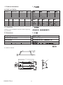
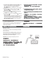
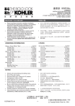
OVE
INSTALLATION INSTRUCTIONS
ACRYLIC WHIRLPOOL
K-1709T K-1709T-H
BEFORE YOU BEGIN
· Please read these instructions carefully to
familiarize yourself with the required tools, materials,
and installation sequences. Follow the sections that
pertain to your particular installation. This will help
you avoid costly mistakes. In addition to proper
installation, read all operating and safety instructions.
· All information is based on the latest product
information available at the time of publication.
Kohler China Ltd. reserves the right to make
changes in product characteristics, packaging, or
availability at any time without notice.
· These instructions contain important care, cleaning,
and warranty information-please leave these
instructions for the consumer.
·
·
·
·
·
·
·
ROUGHING-IN & DIMENSIONS
A.
A. Ordering Information
Hardware:
17295T-CP Optional
Drain
17295T-CP
B. Required Electrical Service
B.
Dedicated branch circuit required, protected with
Class A Ground-Fault Circuit-Interrupt (GFCI):
Pump
Heater HC103P
220~240V
220~240V
5.1A
4.5A
50Hz
50Hz
A
(GFCI)
750W.
1000W.
HC103P
368
1063633-T01-A
-1-
220~240
750
5.1
50
220~240
1000
4.5
50
201419
, 2006
Copyright Kohler China Ltd., 2006
C. Product Information
C.
K-1709T, K-1709T-H
Fixture*
Basin area
Top area
Weight
Bathing well 1092 427mm 1585 625mm 42kg
Water depth
Capacity
To overflow 327mm
214L
* Approximate measurements for comparison only.
Pump
HP
Voltage
1092 427
1585 625
327
214
42
*
Frequency Amperage
1-Speed 1 HP
220~240 V
Heater HP
Voltage
HC103P 1.36HP 220~240 V
50 Hz
5.1A
Frequency Amperage
50~60 Hz 4.5A
HC103P
1
220~240
50
5.1
1.36
220~240
50~60
4.5
D.
D. Installation
Read the entire installation instruction before beginning
the installation.
E. Dimensions
E.
Roughing-In Notes
Fixture conforms to ANSI Standard Z124.1.
All dimensions are nominal.
No change in measurements if connected with
drain illustrated.
Access panel
Pump/Control 500W 400H mm Required
/
500
400
Unit: mm
:
470
457
K-1709T, K-1709T-H
43
1700
84
333
/
750
50
1063633-T01-A
-2-
52
PRODUCT NOTICES
A. Installation Hazard Notification
A.
DANGER: Risk of fire, electric shock, or injury to
Persons. Read important safety instructions on inside
front cover of these instructions.
WARNING: Risk of electrical shock. A licensed
electrician should make all electrical connections.
WARNING: Risk of electrical shock. Connect only to
a circuit protected by a Ground-Fault Circuit-Interrupter
(GFCI) or Earth-Leakage Circuit-Breaker (ELCB).
WARNING: Risk of electrical shock. Disconnect
power before servicing.
WARNING: Risk of injury or property damage.
Please read all instructions thoroughly before beginning
installation, including the following Product
Requirements.
NOTICE: Follow all local plumbing and electrical codes.
(GFCI)
B. Factory-Assembled Features
B.
Factory installed components include pump and air
switch transmitter. No installation is needed.
The whirlpool pump and piping are factory assembled.
WARNING: Unauthorized modification may cause
unsafe operation and poor performance of the
whirlpool. Do not relocate the whirlpool pump, or make
other modifications to the whirlpool system, as this
could adversely affect the performance and safe
operation of the whirlpool. Kohler China shall not be
liable under its warranty or otherwise for personal injury
or damage caused by any such unauthorized
PRODUCT REQUIREMENTS
A. Summary Of Key Requirements
A.
·
·
·
·
·
·
·
·
Observe all local plumbing codes.
Install the unit to a level subfloor.
Provide properly-dimensioned framing.
Baths are designed for a variety of installations,
depending upon the model chosen.
K-1709T
Drop In installation is recommended.
K-1709T
B. Plumbing Specifications
B.
If using a rim-mounted bath faucet, flexible connections
between the valves and spout may be required.
Confirm adequate mounting, connection space of
specified faucet for your installation.
Confirm adequate support for the faucet; large faucets
that may inadvertently used as a means of support are
not appropriate or safe or this installation.
1063633-T01-A
-3-
C. Product Inspection
C.
Carefully unpack and inspect the whirlpool for damage.
Leave all materials in the carton during constructions to
prevent damage.
NOTICE: Make sure both union connections to the
pump are securely tightened.
D. Electrical Connection
D.
1. Pump
The installation must have a 30mA Earth Leakage
Circuit Breaker. The GFCI protects against Line-toGround shock hazard. Use a 220-240V, 10A
(minimum), 50Hz dedicated service for the whirlpool.
2. Heater
1) Should be protected by a ground fault circuit
interrupter (GFCI), The GFCI protects against Lineto-Ground shock hazard. Use a 220-240V,
10A(minimum), 50Hz dedicated service for the
whirlpool.
2) Check the heater label to make sure the rated
voltage is the same to yours.
3) The earth cable uses AWG8 copper leads, and the
heater supplied earth terminal.
1.
E. Clearance Requirements
E.
30mA
GFCI
220-240
/50
10
2.
1)
30mA
GFCI
220-240
/50
10
2)
3)
AWG8
Check the roughing-in and room dimensions to provide
adequate available space for the bath unit.
NOTES: For applicable whirlpool models, if the optional
removable apron is used, the whirlpool must be raised
so the whirlpool support feet are level with the finished
floor.
F.
F. New or Replacement Installation
Requirements
This whirlpool can be installed in new or existing
bathrooms.
For new installations: Position the plumbing
according to roughing-in dimensions beginning on page
2. Cap the supplies, and check for leaks.
For replacement installations: Remove the old bath.
Remove the old wall material (e.g. Ceramic or marble
tiles) and remove any old floor covering from the area.
Remove any old plumbing that does not conform to
roughing-in requirements.
1063633-T01-A
2
(
)
-4-
INSTALLATION REQUIREMENTS
A. Tools Required B. Materials Required
· Adjustable pipe
wrench
· Rule
· Level
· Safety shoes
· Safety glasses
· Square
· Screwdriver
· Pliers
· Utility knife
A.
·
·
·
·
·
B.
·
·
·
·
·
·
Plumbers putty
Wall coverings, as necessary
Silicone sealant
Gypsum cement (optional)
Construction adhesive
(optional)
· Protective covering for
bathtub
· Nails
·
·
·
·
·
·
·
·
(
(
(
·
·
SITE REQUIREMENTS
A.
A. Old Bath Removal (If Applicable)
Disconnect the drain at the trap. Remove the old wall
material. Slip boards under the old bath feet to protect
the floor, and slide the old bath out of the recess as
illustrated.
Old Bath
B. Subfloor Preparation
Floor Protection Boards
B.
Check the floor under the whirlpool, and make repairs
as needed. Make sure the subfloor is level.
C.
C. Whirlpool Area Construction
Preparation
Make sure you allow for access to the pump in the
event the unit requires service. When constructing the
framing, allow for the thickness of sub and finish wall
material (e.g. mortar mix and ceramic or marble tilling).
(
)
Drop In Installation Refer to rough-in notes on page 2
for cut-out details. Make sure the whirlpool is supported
by the supporting feet on the bottom of the whirlpool.
Do not hang the bath by the rim.
2
Bath Rim
1/15" (2mm) Gap
Between Bath Rim
and Framing
2
1063633-T01-A
-5-
)
)
)
BEFORE INSTALLING WHIRLPOOL
A. Your new whirlpool has been manufactured to the
A.
highest possible standards, it has been factory tested
and approved.
B. When removing bath from protective carton DO
B.
NOT LIFT BATH BY PIPE WORK. Inspect for any
possible damage that may have occurred in transit.
C. Identify motor access location before proceeding with
installation.
NOTE NO MOTOR ACCESS NO WARRANTY
SERVICE. Ventilation must be provided in order to
allow heat from motor to dissipate.
C.
A
PROVIDE MOTOR ACCESS AS SHOWN.
D. IMPORTANT: Bath must be installed level on all top
edges.
D.
1063633-T01-A
-6-
E.
E. Partially Install Whirlpool Bath Drain
Install the drain on the whirlpool bath according to the
drain manufacturer's instructions. When installing the
drain overflow tube and hood, be sure to adequately
seal along the edges of the hood to prevent leakage.
Unpack drain (17295T-CP) and ensure that the Control
Cable (9b) is not twisted or awkwardly bent.
Please ensure that the bath is placed on woonden
blocks or bricks to protect the waste body under the
bath.
Installation steps:
1) Fit Drain Gasket Thin
to Strainer
2) Insert Strainer
into hole in bath from upper side.
3) Fit Drain Gasket Thick
to Drain Body Assy á
and Drain Body Assy
to underside of bath.
4) Strainer
to Drain Body Assy
by means of Fix
Do not tighten firmly at this
Screw Strainer
stage.
5) Apply a bead of silicone around the overflow hole, on
the outside of the bath. Smear with silicone the
inside wall of overflow hole.
6) Fit 2nd. Gasket Overflow 14 to Over Flow Body 9a
and offer this assembly to back of overflow opening,
ensuring they are centrally positioned and then
screw Overflow Cover 12 on to central spindle .
Control Cable 9b is not twisted before fully tightening
Overflow Cover 12 . In the event that the Control
Cable is twisted or jammed, the pop-up mechanism
will not operate.
SILICONE
10
12
14 9a
11
Smear with SILICONE
1
2
3
4
(17295T-CP)
9b
5
Bath
6
9
1)
2)
3)
15
4)
17
7 8
16
5)
(
6)
)
14
9a
12
12
1063633-T01-A
9b
-7-
13
9b
7) Centralise Grating
with Waste Body
by lining
up ribs of each directly in line and tighten Fixing
Screw
with a coin or suitable screwdiver.
Do not overtighten - handtight plus 1/4 turn should
be sufficient.
8) Adjust Plug
by twisting Control Knob
to the
'up' position and then fix Plug height by use of
Adjusting Screw 2 .
9) Secure Flexible Pipe 13 by tightening Compression
Nut
against Compression Seal .
7)
10) Set drain pipe 16 , put on nut drain pipe 17 , and then
tighten gasket 15 .
Check if the pop-up mechanism is operating correctly.
If it doesn't the Plug height still needs adjusting or
Control Cable might be twisted or jammed. Proceed
with bath installation only after you've ensured the
drain is operating correctly.
10)
F. Protect Whirlpool Unit
F.
-----
8)
2
9)
13
16
17
15
Position a protective covering or similar material in the
bottom of the the unit. Be careful not to scratch the
surface of the product.
INSTALL THE WHIRLPOOL
Whirlpool Set-In
If the subfloor is not level, some shimming of the bath
will be necessary.
Set the whirlpool into installation. Make sure the unit is
level, and is resting on all supporting feet. Insert the
drain tailpiece into the trap. Apply a bead of silicone
sealant under the rim of the whirlpool.
Bath Rim
1/16" (2mm) Gap
Between Bath Rim
and Framing
NOTICE: Do not hang the whirlpool by the rim.
2
1063633-T01-A
-8-
COMPLETE FINISH WALL
Drop-In Models:
Bath
Silicone Filler
CAUTION: Risk of product damage. Do not
support the weight of the bath by the rim.
Finished tiled Wall
Paste Mortar
Brick or
Concrete Wall
For sunken type installation, construct the ceramic or
marble tiles. Seal the joints between the bath rim and
the tiled wall with silicone sealant.
INSTALL PLUMBING
CAUTION: Risk of damage to bath bottom and subfloor,
Ensure a watertight seal on the bath drain connections.
A. When the bath is securely positioned, connect the
drain to the trap.
NOTE: An access panel will simplify future
maintenance.
B. Install the faucet valving and spout tee. When
drilling bathtub for faucet, ensure sufficient clearance to
avoid brick support wall. Open the hot and cold water
valves and check the supply connections for leaks.
C. Run water into the bath and check the drain
connections for leaks.
D. Fill the whirlpool up to the overflow level and check
overflow unit for leaks.
E. Connect power supply (220V/50Hz, 10A) to motor.
This should be a separato line, direct from the
switchboard.
Connect power supply (220V/50Hz, 10A) to heater.
This should be a separato line, direct from the
switchboard.
A.
B.
C.
D.
E.
10A
220V/50Hz
220V/50Hz
10A
The electrical connections must comply with local
authority regulations and must be done by an
authorized electriclan. Please refer to Spa Pump
Installarion & Operation Instructions sheet.
F. Fill bathtub with water to approximately 40 mm above
the jets and trial run pump for 10-15 minutes. Check all
the fittings for leaks and test the control functions. Switch
off the spa pump and leave the unit filled with water (pump
is not running) for at least another two minutes. Check the
pump and pipes union connections for leaks. Hand
tighten union connections if required.
F.
UNION CONNECTIONS
40mm
10-15
(
1063633-T01-A
)
2
-9-
IMPORTANT: Your spa has been factory tested and
approved. It is the responsability of the installer to test
run the spa check all the fittings for leaks and test the
control functions.
NON OBSERVANCE WILL INVALIDATE FACTORY
WARRANTY.
DRILLING AND CUTTING ACRYLIC
DRILLING: Small holes can be drilled with a twist drill,
but the cutting edge MUST be backed off with an oil
stone (the sharp edge dulled). Large holes must be
drilled with a hole saw. Maximum drill size-12mm. Drill
speeds-6mm 1800 RPM-12 mm 900 RPM.
12mm
6mm 1800
/
12mm 900
NOTE: Always drill from acrylic surface.
CUTTING: If for any reason the acrylic requires cutting,
use a fine tooth hacksaw and proceed with caution.
Edges can be smoothed with a second-cut file and
medium-fine sandpaper. If the surface of the acrylic
should happen to be damaged, it can be restored by
polishing with an abrasive cleaner. Deep scratches can
be removed by rubbing with 600 grade wet & dry
sandpaper then polishing.
600
CLEAN-UP AFTER INSTALLATION
When cleaning up after installation, do not use abrasive
cleansers as they may scratch and dull the surface.
Use warm water and liquid, non-abrasive detergent to
clean the surface.
Stubborn stains, paint, or tar can be removed with
mineral spirits. Do not use cleaners containing solvent.
Plaster can be removed by scraping with wood edge.
Do not use metal scrapers, wire brushes, or other metal
tools. One of the powder type detergents may be used
on a damp cloth to provide mild abrasive action to the
residual plaster.
IMPORTANT CONSUMER INFORMATION
Consumer Responsibilities
Cleaning Acrylic Surfaces: Do not use abrasive
cleansers on any acrylic surfaces, as they will scratch
and dull the surface. Wipe out the bath after each use
to prevent a build-up of soap and scum.
If the acrylic surface becomes dull, an automotive type
rubbing compound may be used on the unit, followed
by an application of paste wax.
2
We recommended:
Rubbing compound mequiars mirror glaze 28 metal
polish (import product) or "green oil".
1063633-T01-A
Mequiars
(
-10-
28
)
(
)
/
LIMITED ONE-YEAR WARRANTY
Plumbing Fixtures and Fittings Limited
One-year Warranty
Kohler plumbing fixtures and fittings are warranted to
be free of manufacturing defects.
This product is warranted for one year from date of
purchase. Kohler China will be responsible for any
problems caused by manufacturing defects provided
with the invoice. Kohler China will, at its election, repair,
replace or make appropriate adjustment where Kohler
China inspection discloses any such defects occurring
in normal usage within one year after purchase.
Implied warranties including that of merchantability and
fitness for a particular purpose are expressly limited in
duration to the duration of this warranty, Kohler China
disclaims any liability for special, incidental or
consequential damages. Damages to the product
caused by misuse, abuse and installation that is not in
accordance with the owner's manual are not covered
by this warranty.
To obtain quick warranty service, please contact your
dealer, or write to Kohler China. (Original sales receipt
must be provided as the proof of purchase.)
(
)
(
Kohler China Investment Company Ltd.
Central Customer Service Center
19/F, Shanghai Square, 138 Huai Hai
Road, Luwan District, Shanghai, PRC
Zip Code: 200021
138
19
200021
This is our exclusive written warranty.
1063633-T01-A
)
-11-