1
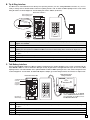
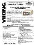
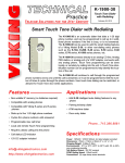
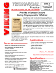
TECHNICAL
Practice
HD-1
Handset Interfaced
Touch Tone Dialer
Practice
TELECOM SOLUTIONS
FOR THE
2 1 S T C E N T U RY
September 23, 2009
Add Touch Tone Capability to
PABX Consoles
The HD-1 Handset Dialer is a universal keypad
Touch Tone generator capable of providing DTMF
signaling.
The HD-1 permits access via DTMF signaling to
beepers, voice mail and banking services from
phone system consoles or other equipment which
cannot provide Touch Tones. The HD-1 is easily
installed in series with modular handsets and headsets or interfaces directly to Tip and Ring.
Features
Applications
• Easily connects in series with handset and
headsets or interfaces directly to tip & ring
with optional adapter kit
• Add DTMF Signaling to Console Phones for:
• Provides DTMF signaling across a dry pair
of wires for in-house applications
• Compatible with console phone auxiliary
handset jacks
• Powered by 9 V battery (provided) or optional
PS-1A 13.8V AC adapter
1.
2.
3.
4.
Beeper paging
Voice mail systems
Automated attendants
Banking services
• Access control (interfaced with an RC-3 or
RC-2A for door/gate control)
Phone...715.386.8861
• "Battery OK" LED indicator
• Adjustable Touch Tone volume control
• Switch selectable transmit (per handset wiring
protocol)
• Optional Talk Battery adapter (PS-1A)
[email protected]
h t t p : / / w w w. v i k i n g e l e c t r o n i c s . c o m
Specifications
Power: 9 Volt battery provided. Optional Viking PS-1A (120V
AC/13.8V AC 1.25A UL listed adapter)
Battery Life: 1 year average (under normal use)
Dimensions: 152mm x 83mm x 44mm (6” x 3.25” x 1.75”)
Shipping Weight: .90 Kg (2 lbs)
Environmental: 0°C to 32°C (32°F to 90°F) with 5% to 95%
non-condensing humidity
Connections: (1) handset plug, (1) handset jack, optional connections: (1) RJ11 plug, RJ11 jack
IF YOU HAVE A PROBLEM WITH A VIKING PRODUCT, PLEASE CONTACT: VIKING TECHNICAL SUPPORT AT (715) 386-8666
Our Technical Support Department is available for assistance Monday 8am - 4pm and Tuesday through Friday 8am - 5pm central time. So that we can give you better service, before you call please:
1. Know the model number, the serial number and what software version you have (see serial label).
2. Have your Technical Practice in front of you.
3. It is best if you are on site.
RETURNING PRODUCT FOR REPAIR
RETURNING PRODUCT FOR EXCHANGE
The following procedure is for equipment that needs repair:
1. Customer must contact Viking's Technical Support Department at 715-386-8666 to obtain a Return Authorization (RA)
number. The customer MUST have a complete description of the problem, with all pertinent information regarding the
defect, such as options set, conditions, symptoms, methods to duplicate problem, frequency of failure, etc.
2. Packing: Return equipment in original box or in proper packing so that damage will not occur while in transit. Static
sensitive equipment such as a circuit board should be in an anti-static bag, sandwiched between foam and individually boxed. All equipment should be wrapped to avoid packing material lodging in or sticking to the equipment. Include
ALL parts of the equipment. C.O.D. or freight collect shipments cannot be accepted. Ship cartons prepaid to:
Viking Electronics, 1531 Industrial Street, Hudson, WI 54016
3. Return shipping address: Be sure to include your return shipping address inside the box. We cannot ship to a PO Box.
4. RA number on carton: In large printing, write the R.A. number on the outside of each carton being returned.
The following procedure is for equipment that has failed out-of-box (within 10 days of purchase):
1. Customer must contact Viking’s Technical Support at 715-386-8666 to determine possible causes for the problem. The
customer MUST be able to step through recommended tests for diagnosis.
2. If the Technical Support Product Specialist determines that the equipment is defective based on the customer's input
and troubleshooting, a Return Authorization (R.A.) number will be issued. This number is valid for fourteen (14)
calendar days from the date of issue.
3. After obtaining the R.A. number, return the approved equipment to your distributor, referencing the R.A. number. Your
distributor will then replace the product over the counter at no charge. The distributor will then return the product to
Viking using the same R.A. number.
4. The distributor will NOT exchange this product without first obtaining the R.A. number from you. If you haven't
followed the steps listed in 1, 2 and 3, be aware that you will have to pay a restocking charge.
LIMITED WARRANTY
Viking warrants its products to be free from defects in the workmanship or materials, under normal use and service, for a period of one year from the date of purchase from any authorized Viking distributor or 18 months from the date manufactured, which ever is greater. If at any time during the warranty period, the product is deemed defective or malfunctions, return the product to Viking Electronics, Inc., 1531 Industrial Street, Hudson, WI., 54016. Customer must contact Viking's
Technical Support Department at 715-386-8666 to obtain a Return Authorization (R.A.) number.
This warranty does not cover any damage to the product due to lightning, over voltage, under voltage, accident, misuse, abuse, negligence or any damage caused by use of the product by the purchaser or others.
NO OTHER WARRANTIES. VIKING MAKES NO WARRANTIES RELATING TO ITS PRODUCTS OTHER THAN AS DESCRIBED ABOVE AND DISCLAIMS ANY EXPRESS OR IMPLIED WARRANTIES OR MERCHANTABILITY OR FITNESS FOR ANY PARTICULAR PURPOSE.
EXCLUSION OF CONSEQUENTIAL DAMAGES. VIKING SHALL NOT, UNDER ANY CIRCUMSTANCES, BE LIABLE TO PURCHASER, OR ANY OTHER PARTY, FOR CONSEQUENTIAL, INCIDENTAL, SPECIAL OR EXEMPLARY DAMAGES ARISING OUT OF OR RELATED TO THE SALE OR USE OF THE PRODUCT SOLD HEREUNDER.
EXCLUSIVE REMEDY AND LIMITATION OF LIABILITY. WHETHER IN AN ACTION BASED ON CONTRACT, TORT (INCLUDING NEGLIGENCE OR STRICT LIABILITY) OR ANY OTHER LEGAL THEORY, ANY LIABILITY OF VIKING SHALL
BE LIMITED TO REPAIR OR REPLACEMENT OF THE PRODUCT, OR AT VIKING'S OPTION, REFUND OF THE PURCHASE PRICE AS THE EXCLUSIVE REMEDY AND ANY LIABILITY OF VIKING SHALL BE SO LIMITED.
IT IS EXPRESSLY UNDERSTOOD AND AGREED THAT EACH AND EVERY PROVISION OF THIS AGREEMENT WHICH PROVIDES FOR DISCLAIMER OF WARRANTIES, EXCLUSION OF CONSEQUENTIAL DAMAGES, AND EXCLUSIVE REMEDY AND LIMITATION OF LIABILITY, ARE SEVERABLE FROM ANY OTHER PROVISION AND EACH PROVISION IS A SEPARABLE AND INDEPENDENT ELEMENT OF RISK ALLOCATION AND IS INTENDED TO BE ENFORCED
AS SUCH.
the necessary modifications to maintain uninterrupted service.
If trouble is experienced with the HD-1, for repair or warranty information, please contact:
Viking Electronics, Inc., 1531 Industrial Street, Hudson, WI 54016 (715) 386-8666
If the equipment is causing harm to the telephone network, the telephone company may request that you disconnect the
equipment until the problem is resolved.
Connection to Party Line Service is subject to State Tariffs. Contact the state public utility commission, public service commission or corporation commission for information.
WHEN PROGRAMMING EMERGENCY NUMBERS AND (OR) MAKING TEST CALLS TO EMERGENCY NUMBERS:
Remain on the line and briefly explain to the dispatcher the reason for the call. Perform such activities in the off-peak
hours, such as early morning or late evenings.
It is recommended that the customer install an AC surge arrester in the AC outlet to which this device is connected. This
is to avoid damaging the equipment caused by local lightning strikes and other electrical surges.
FCC REQUIREMENTS
This equipment complies with Part 68 of the FCC rules and the requirements adopted by the ACTA. On the side of this
equipment is a label that contains, among other information, a product identifier in the format US:AAAEQ##TXXXX. If
requested, this number must be provided to the telephone company.
The REN is used to determine the number of devices that may be connected to a telephone line. Excessive REN's on a
telephone line may result in the devices not ringing in response to an incoming call. In most but not all areas, the sum of
the REN's should not exceed five (5.0) To be certain of the number of devices that may be connected to a line, as determined by the total REN's, contact the local telephone company. For products approved after July 23, 2001, the REN for
this product is part of the product identifier that has the format US:AAAEQ##TXXXX. The digits represented by ## are the
REN without a decimal point (e.g., 03 is a REN of 0.3). For earlier products, the REN is separately shown on the label.
The plug used to connect this equipment to the premises wiring and telephone network must comply with the applicable
FCC Part 68 rules and requirements adopted by the ACTA. If your home has specially wired alarm equipment connected
to the telephone line, ensure the installation of this HD-1 does not disable your alarm equipment. If you have questions
about what will disable alarm equipment, consult your telephone company or a qualified installer.
If the HD-1 causes harm to the telephone network, the telephone company will notify you in advance that temporary discontinuance of service may be required. But if advance notice isn't practical, the telephone company will notify the customer as soon as possible. Also, you will be advised of your right to file a complaint with the FCC if you believe it is necessary.
The telephone company may make changes in its facilities, equipment, operations, or procedures that could affect the
operation of the equipment. If this happens, the telephone company will provide advance notice in order for you to make
PART 15 LIMITATIONS
This equipment has been tested and found to comply with the limits for a Class A digital device, pursuant to Part
15 of the FCC Rules. These limits are designed to provide reasonable protection against harmful interference
when the equipment is operated in a commercial environment. This equipment generates, uses, and can radiate radio frequency energy and, if not installed and used in accordance with the instruction manual, may cause
harmful interference to radio communications. Operation of this equipment in a residential area is likely to cause
harmful interference in which case the user will be required to correct the interference at his own expense.
Installation and Programming
A. Handset Interface
1
2
3
4
5
6
7
8
9
0
#
To Handset Jack
of PABX Console
HANDSET DIALER
Model HD-1
Battery OK
VIKING©
Connect the HD-1 in series with your handset or headset as shown above.
Note: If the handset or headset is terminated with a 5/8” on center twin telephone plug, a modular adapter plug and
socket must be used. Recommended WESTEK part numbers: W478 and PTL-6.
2
B. Tip & Ring Interface
The HD-1 can be used to dial touch tones directly on a Tip & Ring interface (C.O. line, analog PABX/KSU extension, etc.), it is necessary to change from the default handset cord to the Tip/Ring interface cord. To obtain an HD-1 Tip/Ring interface cord, contact
Viking Electronics Technical Support at: 715-386-8666 (part number: 260597, $5.00 each).
Internal View of the HD-1
Modular Handset Jack or
Modular Tip/Ring Jack
J1 Handset Interface
Connector
J1
J2
J2 Tip/Ring Interface
Connector
Pins: 10 9 8 7 6 5 4 3 2 1
4 3 2 1
C B A
1
2
3
4
5
6
7
8
9
0
#
HANDSET DIALER
Model HD-1
Battery OK
VIKING©
9V Battery
Wiring Protocol
Switch
Step 1. Obtain an HD-1 Tip/Ring interface cord (6 ft cord with 4 pin connector, RJ11C plug and jack) from Viking Technical
Support: 715-386-8666.
Step 2. Remove the 4 screws on the back of the HD-1 and remove the cover.
Step 3. Locate J1 (as shown above) and cut the wires on pins 1-8 of the J1 connector. Then remove the cord and modular
handset jack connected to J1. Caution: Do NOT cut the red and black battery wires connected to J1 pins 9 & 10.
Step 4. Connect the Tip/Ring interface cord to J2. Note: Connector position 1 to pin 1 of J2. Slide the modular Tip/Ring jack
into place.
Step 5. Slide Wiring Protocol Switch to position “C” as shown.
Step 6. Replace the back cover and connect the modular cord from the phone to the modular jack on the HD-1.
Step 7. Plug the HD-1 cord into the modular jack the phone was connected to.
C. Talk Battery Interface
With the optional PS-1A installed, the HD-1 is capable of supplying its own 24VDC Talk Battery to be used in conjunction with the
model RC-2A or RC-3 to create a stand alone door/gate security keypad control. This application will require the use of the HD-1
Tip/Ring interface cord and installation of the optional PS-1A. To obtain an HD-1 Tip/Ring interface cord, contact Viking Electronics
Technical Support at: 715-386-8666. To obtain a PS-1A power adapter, go to www.vikingelectronics.com and click on “Spare Parts”.
Model RC-2A or RC-3
Relay Controllers
Internal View of the HD-1
VIKING ©
J3 Talk Battery Interface
Connector
MODEL RC-2A
VIKING
ELECTRONICS
HUDSON, WI 54016
J4
ENTRY CODE
PROGRAMMING
SWITCHES
1
E
ON
789A
1
2
3
4
5
6
2
F0 1 2
E
F0 1 2
S2
S3
#
HANDSET DIALER
Model HD-1
Battery OK
Replaceable 9V
Alkaline Battery
3
F0 1 2
7
S1
0
E
BC D
8
C
BC D
7
N.C.
6
BC D
5
3456
9
C
3456
8
3 4
3456
7
2
COM
1
RELAY
CONTACTS
LINE IN
6
N.O.
5
EARTH
GND
4
REMOTE TOUCH TONE
RELAY CONTROLLER
PWR IN/OUT
12-24V AC/DC
3
789A
2
789A
1
POWER 12V DC
J3
J4 13.8V AC
Connection
for Optional PS-1A
VIKING©
9V Battery
For more information on the RC-2A,
retrieve Fax Back Document 160. For
more information on the RC-3, retrieve
Fax Back Document 165.
Step 1. Follow steps 1-3 as shown in section B above.
Step 2. Connect the Tip/Ring interface cord to J3. Note: Connector position 1 to pin 1 of J3. Slide the modular Tip/Ring jack
into place.
Step 3. Connect the PS-1A (13.8V AC adapter) to J4.
Step 4. Remove the 9V battery and discard.
Step 5. Re-assemble the HD-1.
Note: The Wiring Protocol Switch has no effect in the Talk Battery Interface mode.
3
D. Console Auxiliary Handset Jack
Internal View of the HD-1
The HD-1 can be installed on your console’s auxiliary
handset jack. To eliminate the need for an additional
handset to inject the DTMF signal, simply move the
jumper on J6 (dummy phone load jumper) to positions
1 & 2 as shown below. Refer to Operation, section A
for operating instructions.
Modular Handset Jack
J1 Handset Interface
Connector
J4 13.8V AC
Connection for
Optional PS-1A
J4
J1
J2
J3
J2 Tip/Ring Interface
Connector
J3 Talk Battery Interface
Connector
Less (-)
J6 Dummy Phone Load
Jumper
Wiring Protocol Switch
More (+)
Touch Tone
Volume Control
1
2
3
J5 Touch Tone
Attenuation Jumper
C B A
Replaceable 9V
Alkaline Battery
9V Battery
Operation
A. Handset Interface
Internal View of the HD-1
The HD-1 may require some volume and wiring protocol adjustments to function properly on your telephone. Start with the wiring protocol switch set to the “A” position.
J4
J1
Step 1. Make a test call to an in-house PABX extension.
Step 2. Enter several Touch Tones with the HD-1. The person on the
extension you called should hear loud clear Touch Tones.
J2
J3
J5 Touch Tone
Attenuation Jumper
Step 3. If Touch Tones are not heard, remove the back cover and slide the
wiring protocol switch to the “B” position and try again.
Wiring Protocol Switch
Step 4. If tones are still not heard, slide the wiring protocol switch to the “C”
position and repeat.
1
2
3
C B A
Step 5. If Touch Tones are severely distorted beyond what the volume control
can attenuate, move J5 to the “B” position and retry.
Step 6. If tones are still too distorted, move J5 to the “C” (maximum) position
and then fine tune with volume control.
C
B
A
9V Battery
Note: All outgoing calls must be dialed with your console’s keypad. Once the call is connected, you may use the HD-1.
B. Tip/Ring Interface
The Tip/Ring interface is an easy solution to the over attenuated Touch Tone output caused by certain consoles with built in AGC
(Automatic Gain Control) in their handset transmit circuitry. Connect Tip/Ring interface cord as explained in Installation section B.
The HD-1 can be used by simply going off-hook with your phone, and dialing on the HD-1.
C. Talk Battery Interface
The Talk Battery interface is used for any application where PABX or C.O. talk battery is not available or is too cumbersome to use.
It is ideal for creating a stand alone door/gate security keypad control when used in conjunction with Viking model RC-2A or RC-3.
For more information on Viking’s RC-2A, retrieve Fax Back Document 160. For more information on Viking’s RC-3, retrieve Fax
Back Document 165.
D. Battery O.K. LED
The HD-1 is equipped with a battery test circuit and LED indicator. The battery O.K. LED should light when a key on the keypad is
pressed. If the LED does not light, replace the 9V battery by removing the back cover. The average battery life is approximately 1
year.
Product Support Line...715.386.8666
Fax Back Line...715.386.4345
Due to the dynamic nature of the product design, the information contained in this document is subject to change without notice. Viking Electronics, and its affiliates and/or subsidiaries
assume no responsibility for errors and omissions contained in this information. Revisions of this document or new editions of it may be issued to incorporate such changes.
4
Fax Back Doc 405
Printed in the U.S.A.
ZF290995 Rev 3