1
RP-E10 SERIES
THERMAL PRINTER
TECHNICAL REFERENCE
U00127424203
U00127424200
U00127424201
U00127424202
U00127424203
May 2012
July 2012
September 2012
July 2013
Copyright © 2012-2013 by Seiko Instruments Inc.
All rights reserved.
Seiko Instruments Inc. (hereinafter referred to as "SII") has prepared this manual for use by SII personnel,
licensees, and customers. The information contained herein is the property of SII and shall not be reproduced
in whole or in part without the prior written approval of SII.
SII reserves the right to make changes without notice to the specifications and materials contained herein and
shall not be responsible for any damages (including consequential) caused by reliance on the materials
presented, including but not limited to typographical, arithmetic, or listing errors.
is a trademark of Seiko Instruments Inc.
PREFACE
This technical reference describes about RP-E10 SERIES THERMAL PRINTER
(hereinafter referred to as "printer").
See USER'S GUIDE packed with the printer for operation.
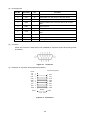
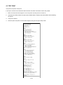
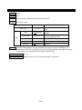
[Product Name]
RP-E10-K 3FJ1-U 1C3
(1)
(2)
(3)
(4)
(1) : Paper Eject Direction
0: From the top / 1: From the front
(2) : Case Color
W: White / K: Black
(3) : Interface
S: Serial / U: USB / E: Ethernet / 1: USB+ serial
(4) : Optional Package Code
Contact us for details.
The printer complies with EU RoHS Directive (2011/65/EU).
Energy Consumption
Energy consumption: 14.988 Wh
Energy consumption (standby mode): 0.354 Wh
PREFACE-1
[Contents]
CHAPTER 1 TERMS USED IN THIS MANUAL
• This chapter describes the basic terms that are frequently used in this manual.
CHAPTER 2 SPECIFICATIONS
• This chapter describes specifications of the printer and the thermal paper.
CHAPTER 3 INTERFACE
• This chapter describes specification of the interface ports.
CHAPTER 4 FUNCTION SETTING
• This chapter describes the Function Setting and test prints.
CHAPTER 5 LED DISPLAY AND SWITCH FUNCTION
• This chapter describes the printer status by LED display and functions of switches.
CHAPTER 6 COMMAND FUNCTIONS
• This chapter describes the function of commands supported by the printer.
APPENDIX A CHARACTER SETS (CHARACTER CODE TABLE)
PREFACE-2
TABLE OF CONTENTS
CHAPTER 1
TERMS USED IN THIS MANUAL
CHAPTER 2
SPECIFICATIONS
2.1
PRINTER SPECIFICATIONS ................................................................................... 2-1
2.1.1
Applicable Standards ............................................................................... 2-3
2.1.2
Precautions For Use ................................................................................ 2-4
2.1.3
Dimensions .............................................................................................. 2-6
2.1.4
Thermal Paper Specifications.................................................................. 2-8
2.1.5
Printing Area ............................................................................................ 2-9
2.1.6
Mark Sensor Specifications ................................................................... 2-10
2.2
CUTTER SPECIFICATIONS .................................................................................. 2-12
2.3
POWER SUPPLY SPECIFICATIONS .................................................................... 2-13
2.4
DRAWER KICK PORT SPECIFICATIONS ............................................................ 2-15
CHAPTER 3
INTERFACE
3.1
USB MODEL ............................................................................................................. 3-1
3.2
SERIAL MODEL........................................................................................................ 3-3
3.1.1
3.2.1
3.3
3.4
4.1
4.2
Serial Interface......................................................................................... 3-3
USB+ SERIAL MODEL ............................................................................................. 3-7
3.3.1
USB Interface .......................................................................................... 3-7
3.3.2
Serial Interface......................................................................................... 3-7
ETHERNET MODEL ............................................................................................... 3-12
3.4.1
CHAPTER 4
USB Interface .......................................................................................... 3-1
Ethernet Interface .................................................................................. 3-12
FUNCTION SETTING
FUNCTION SETTING METHOD .............................................................................. 4-1
4.1.1
Changing DIP Switch ............................................................................... 4-2
4.1.2
Changing Memory Switch ........................................................................ 4-5
TEST PRINT ........................................................................................................... 4-20
TOC-1
CHAPTER 5
LED DISPLAY AND SWITCH FUNCTION
5.1
PRINTER STATUS LED DISPLAY ........................................................................... 5-1
5.2
ERROR AND RECOVERY PROCEDURE ............................................................... 5-3
5.3
SWITCH .................................................................................................................... 5-4
CHAPTER 6
6.1
5.3.1
POWER Switch ....................................................................................... 5-4
5.3.2
FEED Switch............................................................................................ 5-4
COMMAND FUNCTIONS
CHARACTER CODES AND COMMANDS ............................................................... 6-1
6.1.1
JIS Code System ..................................................................................... 6-1
6.1.2
Shift JIS Code System ............................................................................. 6-3
6.2
FLASH MEMORY ..................................................................................................... 6-4
6.3
STANDARD MODE AND PAGE MODE ................................................................. 6-10
6.3.1
Standard Mode ...................................................................................... 6-10
6.3.2
Page Mode ............................................................................................ 6-10
6.4
RESPONSE DATA.................................................................................................. 6-14
6.5
FUNCTION CODE DESCRIPTION ........................................................................ 6-16
6.5.1
6.6
Printing Command ................................................................................. 6-17
6.5.2
Line Spacing .......................................................................................... 6-21
6.5.3
Character Set......................................................................................... 6-22
6.5.4
Print Position.......................................................................................... 6-36
6.5.5
Image ..................................................................................................... 6-47
6.5.6
Macro ..................................................................................................... 6-61
6.5.7
Barcode ................................................................................................. 6-63
6.5.8
Two-dimensional Barcode ..................................................................... 6-72
6.5.9
Kanji ....................................................................................................... 6-77
6.5.10
Auxiliary Functions ................................................................................. 6-85
6.5.11
Ruled Line............................................................................................ 6-112
6.5.12
Download Mode ................................................................................... 6-116
6.5.13
Tag Processing Mode .......................................................................... 6-120
6.5.14
List of Initial Values (at Initialization) .................................................... 6-136
COMMAND LIST .................................................................................................. 6-138
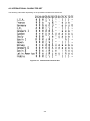
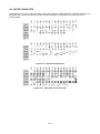
APPENDIX A CHARACTER SETS (CHARACTER CODE TABLE)
A.1
CHARACTER CODE TABLE (CODEPAGE) ............................................................ A-1
A.2
INTERNATIONAL CHARACTER SET ...................................................................... A-9
A.3
2-BYTE CHARACTER ............................................................................................ A-10
TOC-2
FIGURES
Figure 1-1
Relationship between Input Buffer and Line Buffer ................................................... 1-1
Figure 1-2
Line Spacing ............................................................................................................. 1-2
Figure 1-3
Character Spacing .................................................................................................... 1-2
Figure 2-1
RP-E10 Dimensions .................................................................................................. 2-6
Figure 2-2
RP-E11 Dimensions .................................................................................................. 2-7
Figure 2-3
Power Supply Connector (View from Joint Surface) ............................................... 2-13
Figure 3-1
Connector.................................................................................................................. 3-2
Figure 3-2
Connector.................................................................................................................. 3-4
Figure 3-3
Connection ................................................................................................................ 3-4
Figure 3-4
DTR, RTS Output...................................................................................................... 3-5
Figure 3-5
DTR, RTS Output...................................................................................................... 3-5
Figure 3-6
DTR, Xon/Xoff Output ............................................................................................... 3-6
Figure 3-7
Connector.................................................................................................................. 3-8
Figure 3-8
Connection ................................................................................................................ 3-8
Figure 3-9
Connection ................................................................................................................ 3-9
Figure 3-10 DTR, RTS Output...................................................................................................... 3-9
Figure 3-11 DTR, RTS Output.................................................................................................... 3-10
Figure 3-12 DTR, Xon/Xoff Output ............................................................................................. 3-10
Figure 3-13 Connector................................................................................................................ 3-12
Figure 6-1
Mapping of Characters and Image Data ................................................................. 6-12
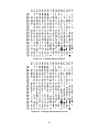
Figure A-1
Codepage 437 (USA, Standard Europe)................................................................... A-1
Figure A-2
Katakana Character Set ............................................................................................ A-2
Figure A-3
Codepage 850 (Multilingual) ..................................................................................... A-2
Figure A-4
Codepage 860 (Portuguese) ..................................................................................... A-3
Figure A-5
Codepage 863 (Canadian-French) ........................................................................... A-3
Figure A-6
Codepage 865 (Nordic) ............................................................................................. A-4
Figure A-7
Codepage 1252 (Latin) ............................................................................................. A-4
Figure A-8
Codepage 852 (Eastern Europe) .............................................................................. A-5
Figure A-9
Codepage 858 (Euro)................................................................................................ A-5
Figure A-10 Codepage 864 (Arabic) ............................................................................................. A-6
Figure A-11 Codepage 1250 (Central European) ......................................................................... A-6
Figure A-12 Codepage 1251 (Cyrillic) ........................................................................................... A-7
Figure A-13 Codepage 1253 (Greek) ........................................................................................... A-7
Figure A-14 Codepage 1254 (Turkish) ......................................................................................... A-8
Figure A-15 International Character Set ....................................................................................... A-9
Figure A-16 Special Character Set ............................................................................................. A-10
Figure A-17 NEC Special Character Set..................................................................................... A-10
Figure A-18 NEC Selection of IBM Extension Character Set ..................................................... A-11
Figure A-19 IBM Extension Character Set .................................................................................. A-12
TOC-3
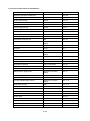
TABLES
Table 2-1
Printer Specifications ................................................................................................ 2-1
Table 2-2
Applicable Standards and Optional Products............................................................ 2-3
Table 2-3
Thermal Paper Specifications ................................................................................... 2-8
Table 2-4
Specified Thermal Paper Specifications ................................................................... 2-8
Table 4-1
Serial Model Function Setting (DS1) ......................................................................... 4-3
Table 4-2
Baud Rate Selection ................................................................................................. 4-3
Table 4-3
Parity Selection ......................................................................................................... 4-3
Table 4-4
USB+ Serial Model Function Setting (DS1) .............................................................. 4-4
Table 4-5
Baud Rate Selection ................................................................................................. 4-4
Table 4-6
Parity Selection ......................................................................................................... 4-4
Table 4-7
Destination and Power Supply Terminal Selection ................................................... 4-4
Table 4-8
General Setting 1 (MS1) ........................................................................................... 4-8
Table 4-9
Standby LED Selection (MS1-4 to 5) ........................................................................ 4-9
Table 4-10
General Setting 2 (MS2) ........................................................................................... 4-9
Table 4-11
Buzzer Count Selection When an Error Occurs (MS2-1 to 2) .................................. 4-9
Table 4-12
Buzzer Pattern Selection When an Error Occurs (MS2-3 to 4) .............................. 4-10
Table 4-13
General Setting 3 (MS3) ......................................................................................... 4-10
Table 4-14
Buzzer Count Selection When Cutting Is Complete (MS3-1 to 2) .......................... 4-11
Table 4-15
Buzzer Pattern Selection When Cutting Is Complete (MS3-3 to 4) ........................ 4-11
Table 4-16
General Setting 4 (MS4) ......................................................................................... 4-12
Table 4-17
Number of Dots Selection for Fixed Division and Dynamic Division (MS4-1 to 2) .. 4-12
Table 4-18
Maximum Print Speed Selection (MS4-7 to 8) ........................................................ 4-13
Table 4-19
General Setting 5 (MS5) ......................................................................................... 4-14
Table 4-20
Initialization Performance Selection After Paper Setting (MS5-6 to 7) ................... 4-14
Table 4-21
General Setting 6 (MS6) ......................................................................................... 4-15
Table 4-22
Print Density Selection (MS6-1 to 8) ....................................................................... 4-15
Table 4-23
General Setting 7 (MS7) ......................................................................................... 4-16
Table 4-24
Thermal Paper Selection (MS7-1 to 8) ................................................................... 4-16
Table 4-25
Mark Position Correction (MS8 to 9) ....................................................................... 4-16
Table 4-26
Mark Detection Maximum Feeding Length Setting (MS10 to 11) ........................... 4-17
Table 4-27
Mark Detection Threshold Value (MS12) ................................................................ 4-17
Table 4-28
Command Setting (MS13) ...................................................................................... 4-17
Table 4-29
International Character Selection (MS15) ............................................................... 4-18
Table 4-30
Character Code Table Setting (MS16) .................................................................... 4-18
Table 4-31
Serial Communication Setting (MS40) .................................................................... 4-19
Table 5-1
Printer Status Signals................................................................................................ 5-1
Table 5-2
LED Flashing Pattern ................................................................................................ 5-2
Table 5-3
Error and Recovery Procedure ................................................................................. 5-3
Table 6-1
Memory Area After Initialization ................................................................................ 6-5
Table 6-2
Number of Bytes of Memory Control Information (User Area) .................................. 6-6
TOC-4
Table 6-3
Commands for Allocating or Freeing Memory Area .................................................. 6-7
Table 6-4
When Only One Print Print Is Desired .................................................................... 6-10
Table 6-5
When Multiple Prints Are Desired ........................................................................... 6-11
Table 6-6
Page Mode Maximum Print Range ......................................................................... 6-13
Table 6-7
Response Identifiers ............................................................................................... 6-14
TOC-5
CHAPTER 1
TERMS USED IN THIS MANUAL
This chapter describes the terms used in this manual.
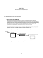
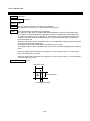
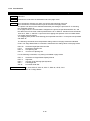
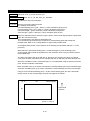
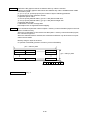
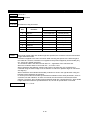
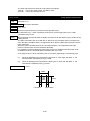
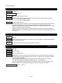
• INPUT BUFFER AND LINE BUFFER
When the RP-E10 (hereinafter referred to as "printer") receives data (character codes and
commands) from the host devices, it stores the data in the printer input buffer. The input buffer has a
capacity of 16K bytes. Then, the printer retrieves data which is stored to the input buffer. When data
is character code, data is mapped to the line buffer. The normal command is executed immediately
when the data is retrieved from the input buffer. Meanwhile, for the realtime command, the
command is executed when the data is stored to the input buffer from the host.
The data capacity of the line buffer is one line. The printer inputs character codes to the line buffer
until the amount of character codes reaches the amount to be printed on one line, then prints the
characters. The printer repeats this operation to print all the character code.
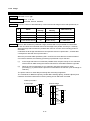
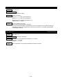
The relationship between the input buffer and line buffer is illustrated in Figure 1-1.
Host Device
Input Buffer
Line Buffer Print Operation
One Line of Characters is Printed
Figure 1-1
Relationship between Input Buffer and Line Buffer
1-1
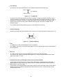
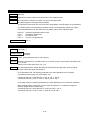
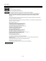
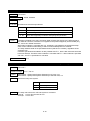
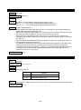
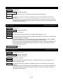
• Line Spacing
Line spacing is the space between the lines of printed characters (See Figure 1-2).
ABC
Line Spacing
ABC
Figure 1-2
Line Spacing
This printer use a line thermal print mechanism, therefore, a paper feed step is necessary before
printing characters or bit images. The line feed command with printing feeds the paper for height of
characters or bit images. Therefore, a paper feed amount which is smaller than character or bit
image height is ignored. Printing with underline feeds the paper 3 dots lines in addition to the
character height.
Line feeding without printing feeds the paper for specified line feed amount.
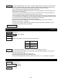
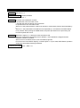
• Character Spacing
Character spacing is the space between each character in the horizontal direction (See Figure 1-3).
A
B
Character Spacing
Figure 1-3
Character Spacing
• Line
The word "line" in this manual indicates a line of characters.
For example, the sentence "the printer feeds paper one line" indicates that the printer feeds paper a
line of characters.
• Dot Line
The word "dot line" in this manual indicates a line of dots in the vertical direction.
For example, the sentence "the printer feeds paper by 1 dot line" indicates that the printer feeds
paper by the space of 1 dot.
• Fixed Division Drive and Dynamic Division Drive of Thermal Head
Logical blocks (physical blocks to be driven at the same time) are predetermined for the fixed
division method. In this method, high quality printing is available because the physical blocks are
always driven in the same order.
Logical blocks are predetermined so that number of dots of the physical block does not exceed the
specified maximum number of simultaneously activated dots for every 1 dot line printing for the
dynamic division drive.
1-2
• Notation in the Technical Reference
Hexadecimal
Hexadecimal is shown as follows;
Example: 0AH (a hexadecimal unit 'H' is added behind a hexadecimal number).
Character string
A character string is shown as follows;
Example: 'G' (a character string 'G' is enclosed with a single quotation mark).
1-3
CHAPTER 2
SPECIFICATIONS
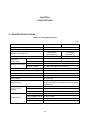
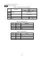
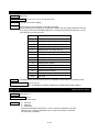
2.1 PRINTER SPECIFICATIONS
Table 2-1
Printer Specifications
(1/2)
Specifications
Paper Width: 80mm
Printing method
*1
8 dots/mm
576 dots/line
*2
(512 dots/line )
Number of effective dots
*2
Printing width
Storage environment
Paper Width: 58mm
Thermal
Dot density
Operating
environment
*1
72 mm (64 mm )
432 dots/line
*2
(360 dots/line )
*2
54 mm (45 mm )
Temperature
5°C to 45°C
Relative humidity
10 %RH to 90 %RH (non-condensing)
Temperature
-20°C to 60°C
Relative humidity
10 %RH to 90 %RH (non-condensing)
*3
Printing speed
350 mm/sec max.
Paper-feed pitch
0.125 mm
Dimensions (excluding projections)
W 129 mm × D 129 mm × H 129 mm
Mass (excluding the thermal paper)
Approx. 1.3 kg
Input voltage
DC24.0 V ±5%
Mounting type
RP-E10 (top paper discharge): place as countertop
RP-E11 (front paper discharge): place as countertop
*4
or wall-mount
Communication
system
Character size
USB
V2.0 Conformity FULL SPEED (12 Mbps)
Serial
RS-232C Conformity (9600 bps to 115200 bps)
Ethernet
10BASE-T/100BASE-TX
1-byte character font A
24 dots × 12 dots
1-byte character font B
16 dots × 8 dots
2-byte character font A
24 dots × 24 dots
2-byte character font B
16 dots × 16 dots
2-1
(2/2)
Specifications
Barcode
*1
Paper Width: 58mm
1-byte character
2-byte character
Kanji character (JIS 1st and 2nd levels, NEC special
character, NEC selection of IBM extension, IBM
extension), user-defined character
*2
36 (30 )
*2
54 (45 )
*2
18 (15 )
*2
27 (22 )
1-byte character font A
48 (42 )
1-byte character font B
72 (64 )
2-byte character font A
24 (21 )
2-byte character font B
36 (32 )
*2
*2
*2
*2
Barcode
UPC-A / UPC-E / JAN-13(EAN-13) / JAN-8(EAN-8) /
ITF / CODABAR / CODE39 / CODE93 / CODE128
Two-dimensional
barcode
QR Code (Model 2) / PDF417
Maxi code / Data matrix
Print mode
Standard mode / Page mode
Input buffer
16K bytes
Autocutter
Drawer kick port
Paper cutting type
Full cut
Partial cut (a tab left at the center)
Drawer drive output
DC24 V, 1 A max., 2 circuits
Drawer switch input
1 circuit
*6
LED
Three-color LED
Operation switch
POWER Switch / FEED Switch
*7
Reliance
*1:
*2:
*3:
*4:
*5:
*6:
*7:
*1
Codepage 437: USA, Standard Europe
Katakana character set
Codepage 850: Multilingual
Codepage 860: Portuguese
Codepage 863: Canadian-French
Codepage 865: Nordic
Codepage 1252: Latin
Codepage 852: Eastern Europe
Codepage 858: Euro
*5
Codepage 864: Arabic
Codepage 1250: Central European
Codepage 1251: Cyrillic
Codepage 1253: Greek
Codepage 1254: Turkish
User-defined character set
Downloaded character, optional font
Font type
Characters per line
Paper Width: 80mm
Abrasion resistance
150 km or more
Activation pulse
resistance
200 million pulses or more
Cutting thermal paper
2 million cut or more
MTBF / MCBF
360000 hours / 70 million lines
Select the paper width by MS4-4 (Paper Width Selection).
When selecting 512/360 dots by MS4-5 (Number of Effective Dots Selection).
The maximum print speed is ensured only when drive voltage is 24V, print rate is 50% or less, and the head temperature is
25°C or higher. However, it may change depending on the connecting time and the printer settings.
Use the special wall mounting kit.
Font B cannot be used when this character set is selected.
Two circuits cannot be driven concurrently.
Reliance is a value at average print ratio 12.5%, print density 100%, ambient temperature and using specified thermal paper.
2-2
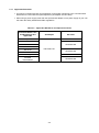
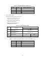
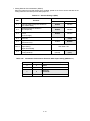
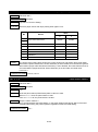
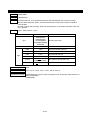
2.1.1 Applicable Standards
• This printer complies with laws and regulations of information equipment in the countries listed
below when it is used with the optional products (AC adapter and AC cable).
• When using a power supply other than the specified AC adapter, use a power supply at your own
risk under the safety standard and EMC regulations.
Table 2-2
Applicable Standards and Optional Products
Countries Where Laws
and Regulations Are
Applicable
AC Adapter
Japan
AC Cable
CB-JP03-20A
USA
Canada
CB-US03-20A
Mexico
EU, EFTA
PW-E2427-W1
CB-CE03-20A
Russia
United Kingdom
CB-UK02-20A
Australia
New Zealand
CB-AU02-20A
2-3
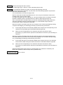
2.1.2 Precautions For Use
• When the two-dimensional barcode and ladder barcode is printed at high speed, it may reduce the
bar code's reading accuracy. In that case, print after reducing the print speed. Use "Print Speed
Specify" command (GS 's' n) to change the print speed.
• When printing the line such as a ruler line, at least 2 dots configuration is needed. In case of a 1 dot
configuration, the printed lines may be invisible.
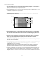
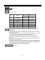
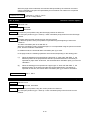
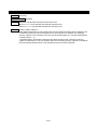
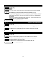
• Always use the printer within the shadowed range depicted in figure below for the relationship
between temperature and humidity.
[% RH]
90
34°C, 90%RH
80
Humidity
70
40°C, 65%RH
60
50
45°C, 50%RH
40
30
20
10
0
10
20
30
40
50
[°C]
Temperature
• When handling this product, be aware of static electricity. When the static electricity is discharged,
this could cause communication failure. When this problem occurs, disconnect the USB connector
that is connected to the host device and wait a few seconds before connecting it again.
• When the printer is left unused for a long period of time, a white powder appears to the surface of
platen. (This is the powder by which an ingredient of a thermal paper was recrystallized.)
When the powder appears to the platen, wipe the platen with ethanol and use the printer after
ethanol has dried completely.
Also, do not use ethanol on the parts except the platen. When ethanol adheres on the parts except
the platen, wipe it off immediately.
• When printing at high print ratio under low temperature or high-humidity environment, steam may be
generated from thermal paper. This may cause the thermal paper to be contaminated or
condensation may occur on the printer.
Make sure that water drops do not fall to the thermal head. It causes galvanic corrosion of the
thermal head. Should condensation occurs, do not apply current until dewdrops disappear.
• To ensure the operability of the front panel, the RP-E11 (front paper discharge) model printer uses
rubber feet that adhere to the printer installation surface. Install the printer on the smooth surface.
When it is installed on the uneven surface, the printer may move during operation, or their surfaces
may peel.
2-4
• When moving the RP-E11 (front paper discharge) model printer from the installation site, lift it
upward slowly to leave the rubber feet from the installation surface. Lifting it rapidly or moving it
horizontally may peel the entire rubber feet or their surfaces.
• Refer to "SAFETY PRECAUTIONS" and "OPERATING PRECAUTIONS" on "RP-E10 SERIES
USER'S GUIDE" which is included with the printer for other precautions.
2-5
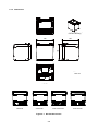
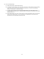
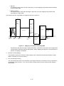
2.1.3 Dimensions
等角投影図(S=1/2)
Isometric
Drawing
129
129
129
単位 :mm
Unit: mm
外形図
USB Model
USBモデル
USB+
Serial Model
USB+シリアルモデル
Serial
Model
シリアルモデル
Figure 2-1
RP-E10 Dimensions
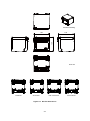
2-6
Ethernet
Model
イーサネットモデル
等角投影図(S=1/2)
Isometric
Drawing
129
129
129
単位 :mm
Unit: mm
外形図
USB Model
USBモデル
Serial Model
USB+ Serial Model
シリアルモデル
Figure 2-2
USB+シリアルモデル
RP-E11 Dimensions
2-7
Ethernet Model
イーサネットモデル
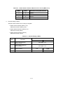
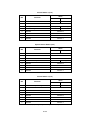
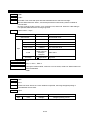
2.1.4 Thermal Paper Specifications
Table 2-3
Thermal Paper Specifications
Item
Specifications
Type
Normal thermal paper roll
Paper width
80
Paper thickness
53 μm to 86 μm
Outside diameter
83 mm max.
Paper roll width
80.5 mm max.
Paper roll core
Internal diameter of core: 12.0 mm
Outer diameter of core: 18.0 mm
Printing surface
Outside
0
-1
mm or 58
0
-1
mm
(NOTE) •
Do not use the paper roll with glued end and taped end.
•
Do not use the paper roll with the deformed paper core.
•
Do not use the paper roll whose paper core is protruded from the paper end.
•
Do not store the paper roll in high-temperature and humidity.
Table 2-4
Specified Thermal Paper Specifications
Model
(NOTE) •
•
Manufacture
TF60KS-E
Nippon Paper Industries Co., Ltd.
PD160R
Oji Paper Co., Ltd.
F220VP
Mitsubishi Paper Mills Ltd.
P220VBB-1
Mitsubishi Paper Mills Ltd.
F5041
Mitsubishi HiTec Paper
KT48FA
Papierfabrik August Koehler AG
Alpha400-2.1
Appleton
Alpha820-3.4
Appleton
Set MS7-1 to 8 (Thermal Paper Selection) for the thermal paper to be used.
Use only specified thermal paper.
2-8
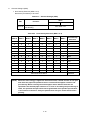
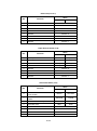
2.1.5 Printing Area
Printing Surface
1st dot
2nd dot
Ath dot
Paper Feed
Direction
0.125 mm
C
B
D
E
MS4-5 (Number of Effective Dots Selection): ON
Symbol
Item
Paper Width: 80 mm
Paper Width: 58 mm
A
Printable dots per line
576 dots
432 dots
B
Left margin
4 ±1 mm
2 ±1 mm
C
Printing area
72 ±0.2 mm
54 ±0.2 mm
D
Right margin
4 ±1 mm
2 ±1 mm
E
80
Paper width
0
−1
mm
0
58 −1 mm
MS4-5 (Number of Effective Dots Selection): OFF
Symbol
Item
Paper Width: 80 mm
Paper Width: 58 mm
A
Printable dots per line
512 dots
360 dots
B
Left margin
8 ±1 mm
6 ±1 mm
C
Printing area
64 ±0.2 mm
45 ±0.2 mm
D
Right margin
8 ±1 mm
7 ±1 mm
E
80
Paper width
2-9
0
−1
mm
0
58 −1 mm
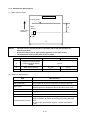
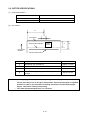
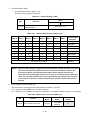
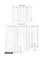
2.1.6 Mark Sensor Specifications
(1) Mark Sensor Position
Printing Surface
Printing Head
Mark
Sensor
A
Paper Feed
Direction
B
C
(NOTE) •
The mark sensor sees back side/non-printable side of the thermal paper for
detecting the mark.
•
Remove the dust such as paper powder regularly on the mark sensor.
•
The detection accuracy of the mark sensor is ±2mm.
Symbol
Item
A
Distance of Printing Head
Position and Mark Sensor
position
B
Mark Sensor position
C
Paper Width: 80 mm
Paper Width: 58 mm
10 mm
5.7 mm
80
Paper width
0
−1
mm
3.7 mm
0
58 −1 mm
(2) Mark Print Specifications
Item
Specifications
Mark print position
Based on the center position of the mark sensor
Mark width (Min.)
5 mm right and left from the reference position (Position B)
Mark height
5 mm min. to 10 mm max.
(Mark height is the length from the top to bottom of the mark.)
Print surface
Non-printing side
PCS
0.9
Reflectivity
900 nm Infrared reflectance should be 8% and below.
Limited area for pre-print
Paper edge (left side) and 10 mm (right side) from the reference
position (Position B) cannot be used for pre-printing with dark
color.
In case of pre-printed thermal paper, evaluate it well before
using.
2-10
(3) How to Use Marked Paper
(a) Enable (ON) the MS1-3 (Mark Mode Selection).
(b) To change the default settings of the mark position correction, the mark detection maximum feeding
length setting, and the mark detection threshold value at power on, use the "Function Setting
Change" command (DC2 'w'). (Optional setting)
(c) The above default settings can be changed with "Marked Paper Form Feed Position Correct"
command (GS 'A' m n) after power on. (Optional setting. The settings are not affected to the default
settings at power on.)
(d) When "Marked Paper Form Feed" command (GS FF) is entered before/after printing, at the timing of
determining the feeding position on the marked paper, the marked paper is fed for the amount
specified by the above setting after detecting the mark.
2-11
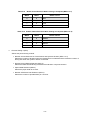
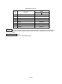
2.2 CUTTER SPECIFICATIONS
(1) Cutter Specifications
Item
Specifications
Paper cutting method
Slide cutting
Cutting frequency
1 cut / 2 s max.
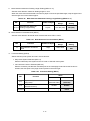
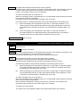
(2) Cut Position
D
Cut Position
A
Printing
Surface
Backward Feed Margin
C
B
Paper Feed
Direction
Printing Head Position
Symbol
(NOTE) •
Item
Dimension
A
Remaining part of partial cut
Approx. 1.5 mm
B
Distance from Cut Position to Printing Head Position
Approx. 12.1 mm
C
Distance from Cut Position to Backward Feed Margin
9.25 mm max.
D
Distance from paper edge (1st dot side) to partial cut
position
Approx. 40 mm
When applying stress to platen such as pulling the thermal paper after partial cut,
uneven pitch may occur at next print start position. Pull the thermal paper to right/left
direction in order to prevent platen from being stressed or feed the thermal paper
approx. 1mm before starting next printing.
•
The cutter may be damaged when it is overused.
2-12
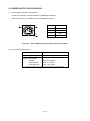
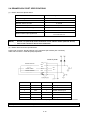
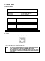
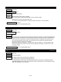
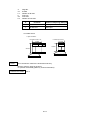
2.3 POWER SUPPLY SPECIFICATIONS
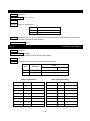
(1) Power Supply Connector Specifications
Printer side connector: TCS7960-5320177 (HOSIDEN) equivalent
Cable side connector: TCP8927-631167 (HOSIDEN) equivalent
3
1
2
Figure 2-3
No.
Function
1
+24 V
2
GND
3
N.C.
Shell
FG
Power Supply Connector (View from Joint Surface)
(2) Power Supply Specifications
Item
Specifications
Power supply voltage
DC22.8 V to DC25.2 V
Current consumption*
Standby
Print ratio 25%
Print ratio 100%
Approx. 40 mA (typ.)
Approx. 4.5 A max.
Approx. 10.0 A max.
*: Under the condition that the driving method is dynamic division 288 dots.
2-13
(3) Specified AC Adapter Specifications (PW-E2427-W1)
Item
Specifications
Input voltage
AC100 V to AC240 V
Input frequency
50 Hz to 60 Hz
Output voltage
DC24 V
Output current
2.71 A
Dimensions
W 115 mm × D 53 mm × H 38 mm
Mass
Approx. 330 g
(4) Specified AC Cable Specifications
Item
Model
Length
Specifications
Japan
CB-JP03-20A
USA, Canada, Mexico
CB-US03-20A
EU, EFTA, Russia
CB-CE03-20A
United Kingdom
CB-UK02-20A
Australia
New Zealand
CB-AU02-20A
Approx. 2 m
2-14
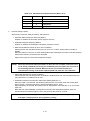
2.4 DRAWER KICK PORT SPECIFICATIONS
(1) Drawer Kick Port Specifications
Item
Specifications
Output voltage
24 V
Output current
1 A max.
Number of drive circuits
2 circuits
Drawer switch input
1 port
Drawer switch drive voltage
3.3 V
Drawer switch drive current
0.07 mA
L: 0.0 V to 0.6 V
H: 2.2 V to 3.3 V
Drawer switch input signal level
(NOTE) •
•
Use the coil (solenoid) whose resistance is over 24Ω for drawer (external device).
Two circuits cannot be driven at the same time.
(2) Drawer Kick Connector Specifications
Printer side connector: MJ-66J-RD315 (JST) equivalent (6P modular jack connector)
Cable side connector: TM3P-66 (HRS) equivalent
Inside of printer
FG
Drawer solenoid
DR1
SW
Drawer switch
24V
Drawer solenoid
DR2
SW
24 V
GND
Pin No.
Pin Name
I/O
Function
1
FG
-
Frame ground
2
DR1
O
Drive circuit 1
3
SW
I
Drawer switch input
4
24V
-
5
DR2
O
Drive circuit 2
6
GND
-
Signal ground
Status of the Pin No.3 (SW) can be detected by using "Automatic Status Back Enable/Disable" command.
(NOTE) •
Do not connect the telephone line to this connector.
2-15
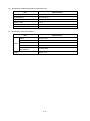
CHAPTER 3
INTERFACE
This chapter describes specifications of each interface required for connecting host devices and peripheral
equipment with the printer.
Irrespective of the interface used, amount of the input buffer in the printer is 16K bytes.
3.1 USB MODEL
3.1.1 USB Interface
(1) General specifications
Item
Specifications
USB version
USB 2.0 conformity
Printer device class 1.1 conformity
Communication speed
Full speed (12 Mbps)
Communication protocol
Bulk transfer
(2) Pin assignment
Pin No.
Pin Name
I/O
Function
1
Vbus
-
2
D-
I/O
USB data
3
D+
I/O
USB data
4
GND
-
Signal ground
Shell
FG
-
Frame ground
USB power supply
(NOTE) Use a USB cable that conforms to the FULL SPEED when you prepare a cable
separately.
3-1
(3) Connector
Printer side connector: UBB-4R-D14T-4D(LF)(SN) (JST) or equivalent (Series B)
Figure 3-1
Connector
(4) Data reception
USB data reception uses a bulk-out transfer method.
Data is received during printing. However, since printing is prioritized, the NAK response may be
returned even when there is free space in the input buffer.
When remaining capacity is less than 64 bytes in the input buffer, the NAK response continues. When
there are 8192 bytes or more remaining in the input buffer after data processing, data reception resumes.
The number of bytes that can be received with one packet is maximum 64 bytes. Data reception is
available during an error.
(5) Data transmission
USB data transmission uses a bulk-in transfer method.
The response data is stored temporarily in the output buffer, and a response is made to the bulk-in
packet request from the host device. When no transmission data exists, no data response is returned
when the bulk-in request is received.
The number of bytes that can be transmitted with one packet is maximum 64 bytes.
(6) iSerialNumber
USB iSerialNumber can be set.
To set iSerialNumber, use the following two ways:
• Using the iSerialNumber setting tool
Use the iSerialNumber setting tool "io_util.exe" in the provided CD-ROM.
• Using the command
See "iSerialNumber Setting" command ("6.5.10 Auxiliary Functions", DC2 'u' 0, DC2 'u' 1).
3-2
(NOTE) •
iSerialNumber is not initially set.
•
Write an iSerialNumber value that does not duplicate others.
•
Do not set iSerialNumber three or more times.
•
iSerialNumber can contain 1-byte character only.
3.2 SERIAL MODEL
3.2.1 Serial Interface
(1) General specifications
Item
Specifications
Synchronization
Asynchronous serial (RS-232C conformity)
Signal level
MARK = -3.0 V to -15.0 V: Logic '1'
SPACE = +3.0 V to +15.0 V: Logic '0'
Baud rate
9600, 19200, 38400, 115200 bps
*1
Data bit length
7 bits, 8 bits
Start bit length
1 bit
Stop bit length
1 bit or more
Parity
No parity, odd, even
Flow control (reception)
DTR/DSR control, RTS/CTS control, Xon/Xoff
Flow control (transmission)
No control, DTR/DSR control, RTS/CTS control
*1:
(Note)
When selecting 7 bits, the data transmission such as the status from a printer is not performed.
Also, the command that uses 80H and more parameters and character printing over 80H are not available.
The underlined value indicates the initial one.
(2) Pin assignment
Pin No.
Pin
Name
I/O
1
N.C.
-
Unconnected terminal
2
TxD
O
Sends data from the printer to the host device.
3
RxD
I
Receives data from the host device.
4
DSR
I
Outputs SPACE when the host device can receive data.
5
GND
-
Signal ground
6
DTR
O
Outputs SPACE when the printer can receive data.
7
CTS
I
Outputs SPACE when the host device can receive data.
8
RTS
O
Outputs SPACE when the printer can receive data.
N.C.
-
Unconnected terminal
FG
-
Frame ground
9
Shell
*1:
*1
Function
Note that this is the power supply terminal in the USB+ serial model.
3-3
(3) Connector
Printer side connector: XM2C-0942-132L (OMRON) or equivalent (D-sub 9P M, fixing screw: #4-40UNC)
Figure 3-2
Connector
(4) Examples of connection with the host device
Printer
Host device
Printer
Host device
FG
1
FG
1
TxD
2
2 RXD
TxD
2
3 RxD
RxD
3
3 TXD
RxD
3
2 TxD
DSR
4
4 DTR
DSR
4
20 DTR
GND
5
5 GND
GND
5
7
DTR
6
6 DSR
DTR
6
6
DSR
CTS
7
7
RTS
CTS
7
4
RTS
RTS
8
8
CTS
RTS
8
5
CTS
N.C.
9
GND
N.C. 9
(Shield)
SHELL
(Shield)
SHELL
SHELL
9-pin - 9-pin
SHELL
9-pin – 25-pin
Figure 3-3
Connection
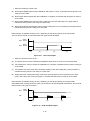
(5) Data reception
• When the DTR/DSR control is set
(a) DTR outputs MARK signal during initialization after power on reset. It indicates that the printer is not
ready to receive data.
(b) DTR outputs SPACE signal after the initialization is complete. It indicates that the printer is ready to
receive data.
(c) DTR outputs MARK signal when remaining capacity is less than 256 bytes in the input buffer. It
indicates that the printer is not ready to receive data.
(d) With progression of data processing, once the remaining buffer gets 8192 bytes or more, DTR
outputs SPACE signal again. It indicates that the printer is ready to receive data.
Data reception is available even under error status when there is enough capacity in the input buffer.
Do not transmit data while the signal of DTR is MARK.
3-4
DTR
MARK
SPACE
RTS
MARK
SPACE
(1)
(2)
Figure 3-4
(3)
(4)
DTR, RTS Output
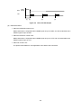
• When the RTS/CTS control is set
(a) RTS outputs MARK signal during initialization after power on reset. It indicates that the printer is not
ready to receive data.
(b) RTS outputs SPACE signal after the initialization is complete. It indicates that the printer is ready to
receive data.
(c) RTS outputs MARK signal when remaining capacity is less than 256 bytes in the input buffer. It
indicates that the printer is not ready to receive data.
(d) RTS outputs SPACE signal again when there are 8192 bytes or more in the input buffer. It indicates
that the printer is ready to receive data.
Data reception is available during an error, depending on remaining capacity in the input buffer.
Do not transmit data while the signal of RTS is MARK.
MARK
DTR SPACE
RTS
MARK
SPACE
(1)
(2)
Figure 3-5
(3)
(4)
DTR, RTS Output
• When the Xon/Xoff control is set
(a) The printer cannot receive data during initialization after power on reset. Do not transmit data.
(b) TxD outputs Xon code (11H) after the initialization is complete. It indicates that the printer is ready to
receive data.
(c) TxD outputs Xoff code (13H) when remaining capacity is less than 256 bytes in the input buffer. It
indicates that the printer is not ready to receive data.
(d) With progression of data processing, when there are 8192 bytes or more remaining in the input
buffer, TxD outputs Xon code (11H) again. It indicates that the printer is ready to receive data.
Data reception is available during an error, depending on remaining capacity in the input buffer.
Immediately after Xoff code (13H) is received, stop data transmission. Do not transmit data until Xon
code (11H) is received.
3-5
DTR
MARK
SPACE
TxD
Xoff
Xon
(1)
(2)
Figure 3-6
(3)
Xon
(4)
DTR, Xon/Xoff Output
(6) Data transmission
• When the DTR/DSR control is set
Data transmission is suspended when MARK signal is input in DSR, and TxD sends data when
SPACE signal is input in DSR.
• When the RTS/CTS control is set
Data transmission is suspended when MARK signal is input in CTS, and TxD sends data when
SPACE signal is input in CTS.
• When No control is set
The printer sends data from TxD regardless of the state of the host device.
3-6
3.3 USB+ SERIAL MODEL
The USB+ serial model provides both USB and serial interfaces, and it can be used in the following ways:
• The USB interface is used for data communication from the host device, and the serial interface is
used for data communication from peripheral equipment such as the barcode reader.
Peripheral equipment can transmit data with the host device through the printer.
• The serial interface is used for data communication from the host device. The USB interface cannot
be used in this setting.
3.3.1 USB Interface
The USB interface specifications are the same as those of the USB interface model. See "3.1.1 USB
Interface" in "3.1 USB MODEL" for details.
3.3.2 Serial Interface
(1) General specifications
Item
Specifications
Synchronization
Asynchronous serial (RS-232C conformity)
Signal level
MARK = -3.0 V to -15.0 V: Logic '1'
SPACE = +3.0 V to +15.0 V: Logic '0'
Baud rate
9600, 19200, 38400, 115200 bps
Data bit length
8 bits
Start bit length
1 bit
Stop bit length
1 bit or more
Parity
No parity, odd, even
Flow control (reception)
DTR/DSR control, RTS/CTS control, Xon/Xoff
Flow control (transmission)
No control, DTR/DSR control, RTS/CTS control
Power supply
*1
Power supply
voltage and output
current
No output, 5 V, 12 V
12 V
DC12 V ±5%, 500 mA max.
5V
DC5 V ±5%, 500 mA max.
The underlined value indicates the initial one.
*1: Be sure to check if the power supply terminal setting is correct before connecting to peripheral equipment or the
host device.
3-7
(2) Pin assignment
Pin No.
Pin Name
I/O
Function
1
N.C.
-
Unconnected terminal
2
TxD
O
Sends data from the printer to the host device.
3
RxD
I
Receives data from the host device.
4
DSR
I
Outputs SPACE when the host device can receive
data.
5
GND
-
Signal ground
6
DTR
O
Outputs SPACE when the printer can receive data.
7
CTS
I
Outputs SPACE when the host device can receive
data.
8
RTS
O
Outputs SPACE when the printer can receive data.
9
PWR
-
Power supply terminal
Shell
FG
-
Frame ground
(3) Connector
Printer side connector: XM2C-0942-132L (OMRON) or equivalent (D-sub 9P M, fixing screw:
#4-40UNC)
Figure 3-7
Connector
(4) Examples of connection with peripheral equipment
Peripheral equipment
Printer
FG
1
TxD
2
3 RxD
RxD
3
2 TxD
DSR
4
6 DTR
GND
5
5 GND
DTR
6
4 DSR
CTS
7
8 RTS
RTS
8
7 CTS
PWR 9
9 PWR
(Shield)
SHELL
SHELL
9-pin - 9-pin
Figure 3-8
Connection
3-8
(5) Examples of connection with the host device
Host device
Printer
Host device
Printer
FG
1
FG
1
TxD
2
2 RxD
TxD
2
3 RxD
RxD
3
3 TxD
RxD
3
2 TxD
DSR
4
4 DTR
DSR
4
20 DTR
GND
5
5 GND
GND
5
7 GND
DTR
6
6 DSR
DTR
6
6
DSR
CTS
7
7 RTS
CTS
7
4
RTS
RTS
8
8 CTS
RTS
8
5
CTS
PWR
9
PWR
9
(Shield)
(Shield)
SHELL
SHELL
SHELL
SHELL
9-pin - 9-pin
9-pin – 25-pin
Figure 3-9
Connection
(6) Data reception
• When the DTR/DSR control is set
(a) DTR outputs MARK signal during initialization after power on reset. It indicates that the printer is not
ready to receive data.
(b) DTR outputs SPACE signal after the initialization is complete. It indicates that the printer is ready to
receive data.
(c) DTR outputs MARK signal when remaining capacity is less than 256 bytes in the input buffer. It
indicates that the printer is not ready to receive data.
(d) With progression of data processing, when there are 8192 bytes or more remaining in the input
buffer, DTR outputs SPACE signal again. It indicates that the printer is ready to receive data.
Data reception is available during an error, depending on remaining capacity in the input buffer.
The host device should not send data while the signal of DTR is MARK.
DTR
MARK
SPACE
RTS
MARK
SPACE
(1)
(2)
Figure 3-10
(3)
DTR, RTS Output
3-9
(4)
• When the RTS/CTS control is set
(a) RTS outputs MARK signal during initialization after power on reset. It indicates that the printer is not
ready to receive data.
(b) RTS outputs SPACE signal after the initialization is complete. It indicates that the printer is ready to
receive data.
(c) RTS outputs MARK signal when remaining capacity is less than 256 bytes in the input buffer. It
indicates that the printer is not ready to receive data.
(d) RTS outputs SPACE signal again when there are 8192 bytes or more remaining in the input buffer. It
indicates that the printer is ready to receive data.
Data reception is available during an error, depending on remaining capacity in the input buffer.
The host device should not send data while the signal of RTS is MARK.
MARK
DTR SPACE
RTS
MARK
SPACE
(1)
(3)
(2)
Figure 3-11
(4)
DTR, RTS Output
• When the Xon/Xoff control is set
(a) The printer cannot receive data during initialization after power on reset. Do not transmit data.
(b) TxD outputs Xon code (11H) after the initialization is complete. It indicates that the printer is ready to
receive data.
(c) TxD outputs Xoff code (13H) when remaining capacity is less than 256 bytes in the input buffer. It
indicates that the printer is not ready to receive data.
(d) With progression of data processing, when there are 8192 bytes or more remaining in the input
buffer, TxD outputs Xon code (11H) again. It indicates that the printer is ready to receive data.
Data reception is available during an error, depending on remaining capacity in the input buffer.
Immediately after receiving Xoff code (13H), the host device should stop data transmission. Do not send
data until Xon code (11H) is received.
DTR
TxD
MARK
SPACE
Xon
Xoff
(1) (2)
Figure 3-12
(3)
DTR, Xon/Xoff Output
3-10
Xon
(4)
(7) Data transmission
• When the DTR/DSR control is set
Data transmission is suspended when MARK signal is input in DSR, and TxD sends data when
SPACE signal is input in DSR.
• When the RTS/CTS control is set
Data transmission is suspended when MARK signal is input in CTS, and TxD sends data when
SPACE signal is input in CTS.
• When No control is set
The printer sends data from TxD regardless of the state of the host device.
3-11
3.4 ETHERNET MODEL
3.4.1 Ethernet Interface
(1) General specifications
Item
Specifications
Communication standards
10Base-T / 100Base-TX
Communication protocol
Basic protocol
Print protocol
IPv4 / ARP / ICMP / UDP / TCP
LPR / TCP Socket Port
(2) Pin assignment
Pin No.
Pin Name
I/O
Function
1
TXP
I/O
Transmission+
2
TXN
I/O
Transmission-
3
RXP
I/O
Reception+
4
N.C.
-
-
5
N.C.
-
-
6
RXN
I/O
7
N.C.
-
-
8
N.C.
-
-
Reception-
(NOTE) Use a cable that conforms to the category 5 or higher.
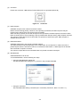
(3) Connector
Printer side connector: RJLDC-308TA (TAIMAG) or equivalent (RJ-45)
Figure 3-13
Connector
Push the LAN cable into the LAN connector until it clicks.
(NOTE) •
Do not insert a customer display connector cable, drawer kick out connector
cable, and general public line to the 10/100BASE-T LAN connector.
•
Be sure to connect the aerially wired LAN cable outside through other devices
where measures are taken to prevent surge. Otherwise, induced lightning may
crash devices.
3-12
(4) LED
Displays of each LED installed on both sides in the bottom of the connector mean the following:
Network Communication System
Display
LED (Orange)
Full Duplex
On
Half Duplex
Off
Network Status Display
Display
LED (Green)
Connected
On
Disconnected
Off
Data transferred
Blinking
(5) Switch
Hold down the switch on the side of the connector and turn the printer on. When you continue to press it
until the printer initialization is complete, items about Ethernet communications are initialized to the
factory default settings.
(6) Protocol
Basic communication protocol
IPv4/ARP/ICMP/UDP/TCP
Print communication protocol
LPR: Transfers print data.
Port No.
515
Maximum number of
concurrent connections
9 (including connections through other protocols such as TCP
Socket Port)
Number of printable
connections
1 (other users wait the completion of printing)
Timeout
Approx. 4 minutes
TCP Socket Port:
Transfers print data and printer status through the two-way
direct socket communication.
Port type
Direct print TCP communication port
Port No.
9100
Port communication direction
Two-way
Maximum number of
concurrent connections
9 (including connections through other protocols such as TCP
Socket Port)
Number of printable
connections
1 (other users wait the completion of printing)
Timeout
Approx. 5 minutes (it can be changed)
3-13
Protocol for getting and setting the status:
Port No.
80
HTTP version
HTTP/1.1
Protocol for monitoring settings:
Gets and changes the printer status and network
parameters on the special Web page, using the HTTP
protocol.
Monitors and sets settings, using the SNMP protocol.
SNMP version
SNMPV2
Server port No.
161
Trap transmission port No.
162
Trap destination
One IP address can be set (the initial status is not set)
Enabled PDU
Get Request, Get Next Request, Get Response, Set Request
Community name
Public
Enabled MIB
Some of MIB-II (RFC1213)
Protocol for Firmware update:
Upgrades the firmware of the LAN module, using the TFTP
protocol.
Transfer request port No.
69
Maximum number of concurrent connections
1
3-14
CHAPTER 4
FUNCTION SETTING
4.1 FUNCTION SETTING METHOD
In this printer, you can preset initial values of items that can be selected after power on, such as
communication system and thermal paper type. Preset these functions before using the printer. Details for
settings of the software switches are described below.
The serial model and USB+ serial model printers mount a DIP switch (hereinafter referred to as "DS") on the
interface board. The DS switch can be used to set serial communication and others.
The Function Setting other than the above serial communication settings are allocated to a memory switch
(hereinafter referred to as "MS") that is stored in the FLASH memory. These are enabled until they are
rewritten.
The Function Setting can be set by using MS1 to 40. MS12 to 27, 31 to 34, and 36 to 39 are reserved for the
system. Do not rewrite them. The value indicated by the shaded cell in the table is the default setting value at
the shipping.
(NOTE) Be sure to set the directed value as "Fixed" according to ON or OFF in list so that
the printer works correctly.
4-1
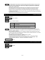
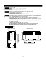
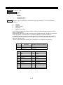
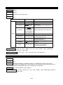
4.1.1 Changing DIP Switch
(1) Change procedures
DS is mounted on the interface board of the serial model and USB+ serial model printers.
1.
As shown in the figure below, remove the two screws fixing the board and then grasp the cable hook in
the center to pull out the board.
2.
When the board is pulled out, DS is mounted on the place shown as below. Use the tip of the driver to
change the switch.
DIP Switch
DIP Switch
Serial Interface
3.
USB+Serial Interface
After setting DS, insert the board straight as far as it will go and fix it with the screws again.
(NOTE) DS is not mounted on the interface board of the USB model and Ethernet model
printers. Do not pull out the board.
4-2
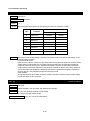
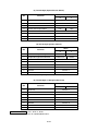
(2) Serial Model Function Setting (DS1)
indicates the initial setting.
Table 4-1
Serial Model Function Setting (DS1)
Setting
DS
Function
ON
1-1
1-2
1-3
1-4
OFF
Baud Rate
See table below
Parity
See table below
1-5
Bit Length
1-6
Unused
7 bit
8 bit
-
Fixed
Note: The USB+ serial model settings are different from those in this table.
Table 4-2
Baud Rate Selection
DS1-2
DS1-1
ON
ON
9600
ON
OFF
19200
OFF
ON
38400
OFF
OFF
115200
Table 4-3
Baud Rate
Parity Selection
DS1-4
DS1-3
Parity
ON
ON
Even
ON
OFF
None
OFF
ON
Odd
OFF
OFF
None
4-3
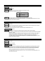
(3) USB+ Serial Model Function Setting (DS1)
indicates the initial setting.
Table 4-4
USB+ Serial Model Function Setting (DS1)
Setting
DS
Function
ON
1-1
1-2
1-3
1-4
1-5
1-6
OFF
Baud Rate
See table below
Parity
See table below
Destination and Power Supply
Terminal of Serial Interface
See table below
Note: The serial model settings are different from those in this table.
Table 4-5
Baud Rate Selection
DS1-2
DS1-1
Baud Rate
ON
ON
9600
ON
OFF
19200
OFF
ON
38400
OFF
OFF
115200
Table 4-6
Parity Selection
DS1-4
DS1-3
ON
ON
Even
ON
OFF
None
OFF
ON
Odd
OFF
OFF
None
Table 4-7
Parity
Destination and Power Supply Terminal Selection
Power Supply
Terminal
DS1-6
DS1-5
Destination
ON
ON
Host device
Not output
ON
OFF
Peripheral equipment
12 V
OFF
ON
Peripheral equipment
5V
OFF
OFF
Peripheral equipment Not output
*1
*1: USB cannot be used in this setting.
4-4
4.1.2 Changing Memory Switch
(1) Change procedures
There are three ways to change the MS.
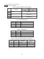
• Using the memory switch setting tool
As shown in the figure below, utilize the memory switch setting tool from the printer driver property.
• Using the "Function Setting Change" command
See DC2 'k', DC2 'w' in "6.5.10 Auxiliary Functions".
• Using the switch operation
You can change MS manually by using the printer POWER Switch and FEED Switch.
The procedures are described in the pages below.
4-5
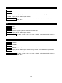
(2) How to set the Function Setting using the switch operation
To set functions using the switch, follow the procedures below.
1.
Set a thermal paper, check that no error occurs, and then continue to press the printer POWER Switch to
turn it off.
2.
Hold down the FEED Switch, and press the POWER Switch and release it. Test print starts, and you
should still hold down the FEED Switch.
3.
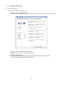
After the test print is complete, the printer enters the Function Setting mode or prints a message.
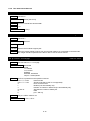
Press the FEED Switch to enter the Function Setting mode.
[Enter Setting Mode]
Enter Setting Mode: Feed SW / Exit: Power SW
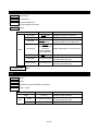
4.
When the printer enters the Function Setting mode, a message for selecting MS to be set is printed.
Press the FEED Switch for the number of times corresponding to the selected MS number, and then
press the POWER Switch.
[MS Selection]
0 Exit
1 MS1
2 MS2
3 MS3
4 MS4
5 MS5
6 MS6
7 MS7
8 MS13
9 International Character
10 Character Code Table
11 Default Setting
Press the FEED switch an equal number of times to the selected
number.
After that, press the POWER SW.
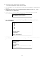
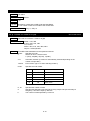
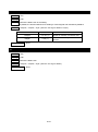
5.
A message for selecting the functions allocated to the selected MS is printed.
Press the FEED Switch for the number of times corresponding to the selected function number, and then
press the POWER Switch.
[Function selection of MS1]
0 Return to MS selection.
1 Mark Mode
2 Standby LED
3 Near end sensor
4 Auto Activation by AC
5 Power SW
Press the FEED switch an equal number of times to the selected
number.
After that, press the POWER SW.
4-6
6.
A message for selecting the setting value of the selected function is printed.
Press the FEED switch for the number of times corresponding to the selected setting value number, and
then press the POWER Switch.
[Standby LED]
0 Return to function selection.
1 AQUA
2 GREEN
3 OFF
4 BLUE
Press the FEED switch an equal number of times to the selected
number.
After that, press the POWER SW.
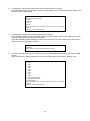
7.
A message for confirming the selected setting value is printed.
Press the FEED Switch to write the setting value to the memory and to return to the initial screen of the
Function Setting mode (step (5) in this procedure).
Press the POWER Switch to discard the selected item and to return to the initial screen of the Function
Setting mode (step (5) in this procedure).
[Standby LED]
Set AQUA
Save setting: Feed SW / Discard setting: Power SW
8.
To exit the Function Setting mode, select 0:Exit. (Press the POWER Switch without pressing the FEED
Switch.)
After exiting from the Function Setting mode, test print starts again. Check that the function is set.
[MS Selection]
0 Exit
1 MS1
2 MS2
3 MS3
4 MS4
5 MS5
6 MS6
7 MS7
8 MS13
9 International Character
10 Character Code Table
11 Default Setting
Press the FEED switch an equal number of times to the selected
number.
After that, press the POWER SW.
4-7
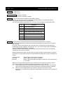
(3) Function Setting (MS)
Details for each setting are described below. The value indicated by the shaded cell (boldface) in the
table is set at the shipping.
(NOTE) Be sure to set the directed value as "Fixed" according to 0 or 1 in the table. For
reserved area, be sure to set the specified value. Otherwise, the printer may not
work correctly or may crash. Reserved values may be changed.
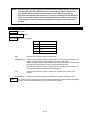
1.
General Setting 1 (MS1)
Sets the printer and selects peripheral equipment.
• Mark Mode Selection (MS1-3)
Enables or disables the mark detection.
• Standby LED Selection (MS1-4 to 5)
Selects LED colors in the standby mode.
• Near-end Sensor Function Selection (MS1-6)
Enables or disables the near-end sensor function.
• Auto Activation by AC Selection (MS1-7)
When this setting is enabled, insert the AC cable of the specified AC adapter into a socket to turn
the printer on.
• POWER Switch Function Selection (MS1-8)
Enables or disables the POWER Switch of the printer.
Table 4-8
General Setting 1 (MS1)
Value
MS
Function
0
1
1-1
Reserved
-
Fixed
1-2
Reserved
-
Fixed
1-3
Mark Mode Selection
(Mark Mode)
Disable
Enable
1-4 to 5
Standby LED Selection
(Standby LED)
See Table 4-9
1-6
Near-end Sensor Function
Selection
(Near End Sensor)
Disable
Enable
1-7
Auto Activation by AC Selection
(Auto Activation by AC)
Disable
Enable
1-8
POWER Switch Function Selection
(Power SW)
Disable
Enable
4-8
Table 4-9
2.
Standby LED Selection (MS1-4 to 5)
MS1-5
MS1-4
Standby LED Selection
0
0
Aqua
0
1
Green
1
0
Off
1
1
Blue
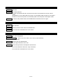
General Setting 2 (MS2)
Sets the buzzer behavior when an error occurs.
• Buzzer Count Selection (MS2-1 to 2)
Selects the buzzer rumbling count.
• Buzzer Pattern Selection (MS2-3 to 4)
Selects the buzzer pattern.
• Buzzer Volume Selection (MS2-5)
Selects the buzzer volume.
Table 4-10
General Setting 2 (MS2)
Value
MS
Function
0
1
2-1 to 2
Buzzer Count Selection
(Buzzer Count)
See Table 4-11
2-3 to 4
Buzzer Pattern Selection
(Buzzer Pattern)
See Table 4-12
2-5
Buzzer Volume Selection
(Buzzer Volume)
2-6 to 8 Reserved
Table 4-11
Low
Loud
-
Fixed
Buzzer Count Selection When an Error Occurs (MS2-1 to 2)
MS2-2
MS2-1
Buzzer Count
0
0
None
0
1
Once
1
0
Thrice
1
1
Continue
4-9
Table 4-12
3.
Buzzer Pattern Selection When an Error Occurs (MS2-3 to 4)
MS2-4
MS2-3
Maximum Print Speed Selection
0
0
Pattern1
0
1
Pattern2
1
0
Pattern3
1
1
Pattern4
General Setting 3 (MS3)
Sets the buzzer behavior when cutting is complete.
• Buzzer Count Selection (MS3-1 to 2)
Selects the buzzer rumbling count.
• Buzzer Pattern Selection (MS3-3 to 4)
Selects the buzzer pattern.
• Buzzer Volume Selection (MS3-5)
Selects the buzzer volume.
Table 4-13
General Setting 3 (MS3)
Value
MS
Function
0
1
3-1 to 2
Buzzer Count Selection
(Buzzer Count)
See Table 4-14
3-3 to 4
Buzzer Pattern Selection
(Buzzer Pattern)
See Table 4-15
3-5
Buzzer Volume Selection
(Buzzer Volume)
3-6 to 8 Reserved
4-10
Low
Loud
-
Fixed
Table 4-14
MS3-2
MS3-1
0
0
None
0
1
Once
1
0
Thrice
1
1
Five Times
Table 4-15
4.
Buzzer Count Selection When Cutting Is Complete (MS3-1 to 2)
Buzzer Count
Buzzer Pattern Selection When Cutting Is Complete (MS3-3 to 4)
MS3-4
MS3-3
Buzzer Pattern
0
0
Pattern1
0
1
Pattern2
1
0
Pattern3
1
1
Pattern4
General Setting 4 (MS4)
Selects the printer driving method.
• Number of Dots Selection for Fixed Division and Dynamic Division (MS4-1 to 2)
Selects the number of divisions when the fixed division is selected and the maximum number of
driving dots when the dynamic division is selected.
• Division Driving Method Selection (MS4-3)
Selects the thermal head driving method as fixed division or dynamic division.
• Paper Width Selection (MS4-4)
Selects the paper width to be used.
• Number of Effective Dots Selection (MS4-5)
Selects the number of printable dots per 1 dot line.
4-11
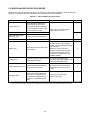
• Maximum Print Speed Selection (MS4-7 to 8)
Selects the maximum print speed at four levels.
High:
Middle(Silent):
Middle(Quality):
Drives at the maximum speed of 350mm/sec.
Drives at the maximum speed of 280mm/sec to reduce operation sound.
Drives at the maximum speed of 150mm/sec for image printing to improve
the quality of image printing. Image printing includes the following:
Raster bit image, graphics data stored in print buffer, NV graphics,
downloaded bit image, bit image mode, barcode, two-dimensional barcode
Drives at the maximum speed of 150mm/sec for the page print by page
mode, since the whole page is regarded as image printing.
Drives at the maximum speed of 150mm/sec to improve the quality of all
printing.
The speed may be lower than the selected maximum speed due to the
thermal head driving method, environmental temperature, and
communication methods.
Low:
Table 4-16
General Setting 4 (MS4)
Value
MS
Function
0
Number of Dots Selection for Fixed
4-1 to 2 Division and Dynamic Division
(Division Method)
4-3
Division Driving Method Selection
(Head Drive)
4-4
Paper Width Selection
(Paper Width)
4-5
Number of Effective Dots Selection
(Number of Effective Dots)
4-6
Reserved
4-7 to 8
Table 4-17
Maximum Print Speed Selection
(Print Speed)
1
See Table 4-17
Fixed
Dynamic
58 mm
80 mm
512/360 dots
576/432 dots
-
Fixed
See Table 4-18
Number of Dots Selection for Fixed Division and Dynamic Division (MS4-1 to 2)
Fixed Division and Dynamic Division,
Number of Dots Selection
MS4-2
MS4-1
0
0
Fixed four divisions/dynamic 64 dots
(4 div./64 dots)
0
1
Fixed four divisions/dynamic 144 dots
(4 div./144 dots)
1
0
Fixed four divisions/dynamic 144 dots
(4 div./144 dots)
1
1
Fixed two divisions/dynamic 288 dots
(2 div./288 dots)
*1
*1: When dynamic 64 dots is selected, the print percentage should be 50% or less.
Otherwise, the print result may degrade.
4-12
Table 4-18
5.
Maximum Print Speed Selection (MS4-7 to 8)
MS4-8
MS4-7
Maximum Print Speed Selection
0
0
Low
0
1
Middle(Quality)
1
0
Middle(Silent)
1
1
High
General Setting 5 (MS5)
Sets various responses, data processing, and behaviors.
• Automatic Status Response Selection (MS5-1)
Enables or disables the automatic status response function.
• Initialized Response Selection (MS5-2)
Enables or disables the initialization completion response function.
• Data Discard Selection When an Error Occurs (MS5-3)
Selects whether the data discard when an error occurs or in return-waiting status is Enable or
Disable.
When the status is in an error or return-waiting status after selecting this function as Enable, printing
data and the following commands are discarded.
Paper Feed, Paper Cut, Execution Response Request
(NOTE) When the Data Discard Selection When an Error Occurs is Enable, and when errors
occur during command processing, the command processing does not end until all
the remaining data are received. When the errors occur while the data is in
command processing, send all the remaining data and enter the next command.
• Paper-Near-End Sensor Selection (MS5-5)
Selects whether the print stop function is enabled or disabled when the near-end detected by the
near-end sensor is considered as an error.
• Initialization Performance Selection After Paper Setting (MS5-6 to 7)
When the initial cut is selected, the following initial process occurs after paper set: feed a paper
approx. 20mm, cut the thermal paper, and feed the paper approx. 2mm.
When Stamp&cut is selected, the initial process of "Stamp&cut" command (GS 'Y' n) occurs after
paper set.
Note that even when Standard or Stamp&cut is selected, the Stamp&cut operation does not
performed when the thermal paper is set in the printer at the power on or reset.
(NOTE) At performance of Stamp&cut, the print result may degrade due to a printer pause
and paper cutting operation during graphics printing.
4-13
• Cutting Method After Initialization (MS5-8)
When the Initial Process After Paper Set is enabled, partial cut or full cut can be selected as the
cutting method in the initial process after paper set.
Table 4-19
General Setting 5 (MS5)
Value
MS
Function
0
1
5-1
Automatic Status Response Selection
(Auto Status Back)
Enable
Disable
5-2
Initialized Response Selection
(Init. Response)
Enable
Disable
5-3
Data Discard Selection When an Error
Occurs
(Error Through)
Enable
Disable
5-4
Reserved
-
Fixed
5-5
Paper-Near-End Sensor Selection
(Near End Error)
Enable
Disable
Initialization Performance Selection After
5-6 to 7 Paper Setting
(Paper Set Handle)
5-8
Cutting Method After Initialization
(Cutting Method)
Table 4-20
See Table 4-20
Partial cut
(Partial)
Full cut
(Full)
Initialization Performance Selection After Paper Setting (MS5-6 to 7)
MS5-7
MS5-6
Initial Process After Paper Set
0
0
Disable
0
1
Stamp&cut
1
0
Initial cut
(Standard)
1
1
Disable
4-14
6.
General Setting 6 (MS6)
• Print Density Selection (MS6-1 to 8)
Selects the print density to be used.
Table 4-21
General Setting 6 (MS6)
Value
MS
Function
0
6-1 to 8
Print Density Selection
(Print Density)
Table 4-22
1
See Table 4-22
Print Density Selection (MS6-1 to 8)
Print Density
Selection
MS6-8
MS6-7
MS6-6
MS6-5
MS6-4
MS6-3
MS6-2
MS6-1
0
0
0
0
0
0
0
0
70%
0
0
0
0
0
0
0
1
75%
0
0
0
0
0
0
1
0
80%
0
0
0
0
0
0
1
1
85%
0
0
0
0
0
1
0
0
90%
0
0
0
0
0
1
0
1
95%
0
0
0
0
0
1
1
0
100%
0
0
0
0
0
1
1
1
105%
0
0
0
0
1
0
0
0
110%
0
0
0
0
1
0
0
1
115%
0
0
0
0
1
0
1
0
120%
0
0
0
0
1
0
1
1
125%
0
0
0
0
1
1
0
0
130%
Other than those above
Prohibition
(NOTE) When too much energy is applied to the thermal head, it would shorten its life span
and cause the paper feed problem. Set an accurate thermal paper selection and
print density. When selecting the thermal paper that is different from the one
specified in the thermal paper selection or in case of not setting the print density in
100%, the specified life span would not be guaranteed of the product specification
in this technical reference. Verify the performance with your actual device before
printing.
4-15
7.
General Setting 7 (MS7)
• Thermal Paper Selection (MS7-1 to 8)
Selects the thermal paper to be used.
Table 4-23
General Setting 7 (MS7)
Value
MS
Function
0
Thermal Paper Selection
(Thermal Paper)
7-1 to 8
Table 4-24
1
See Table 4-24
Thermal Paper Selection (MS7-1 to 8)
Thermal Paper
Selection
MS7-8
MS7-7
MS7-6
MS7-5
MS7-4
MS7-3
MS7-2
MS7-1
0
0
0
0
0
0
0
0
PD160R-N
0
0
0
0
0
0
0
1
P220VBB1
0
0
0
0
0
0
1
0
TF60KS-E
0
0
0
0
0
0
1
1
F5041
0
0
0
0
0
1
0
0
KT48FA
0
0
0
0
0
1
0
1
Alpha 400-2.1
0
0
0
0
0
1
1
0
Alpha 820-3.4
0
0
0
0
0
1
1
1
F220VP
Other than those above
Prohibition
(NOTE) When too much energy is applied to the thermal head, it would shorten its life span
and cause the paper feed problem. Set an accurate thermal paper selection and
print density. When selecting the thermal paper that is different from the one
specified in the thermal paper selection or in case of not setting the print density in
100%, the specified life span would not be guaranteed of the product specification
in this technical reference. Verify the performance with your actual device before
printing.
8.
Mark Position Correction (MS8 to 9)
Sets the direction and length of the mark position correction in 1 dot line.
For 1 (0001H) to 2400 (0960H), the direction is forward.
For -1 (FFFFH) to -74 (FFB6H), the direction is backward. The negative number is set in 2's complement.
Table 4-25
MS
8 to 9
Mark Position Correction (MS8 to 9)
Function
Mark Position Correction
Number of
Bytes
Definition
Range
Default
Setting
2 bytes
-74 to 2400
(dot line)
0
4-16
9.
Mark Detection Maximum Feeding Length Setting (MS10 to 11)
Sets the mark detection maximum feeding length in 1mm.
When the mark cannot be detected even when a paper is fed at the specified length, stop the paper feed
at that length and cut the thermal paper.
Table 4-26
MS
Mark Detection Maximum Feeding Length Setting (MS10 to 11)
Function
10 to 11
Mark Detection Maximum
Feeding Length Setting
Number of Bytes
Definition
Range
Default
Setting
2 bytes
0 to 300 (mm)
300 (mm)
10. Mark Detection Threshold Value (MS12)
Sets the mark detection threshold value at 255 levels where FFH is 100%.
Table 4-27
MS
12
Mark Detection Threshold Value (MS12)
Function
Mark Detection Threshold
Value
Number of Bytes
Definition
Range
Default
Setting
1 byte
10H to EFH
80H
11. Command Setting (MS13)
Selects the kanji code system and 180° reverse function.
• Kanji Code System Selection (MS13-1)
Sets the initial kanji code system to the JIS code or Shift-JIS code system.
• 180° Reverse Function Selection (MS13-2)
Sets the character print direction and start point in the initial page mode. When this function is
enabled, the start point in the page mode is placed in the lower right.
Table 4-28
Command Setting (MS13)
Value
MS
Function
13-1
Kanji Code System
(Kanji Code)
13-2
180° Reverse Function Selection
(Reverse Function)
13-3 to 8 Reserved
4-17
0
1
Shift-JIS code
(Shift-JIS Code)
JIS code
(JIS Code)
Enable
Disable
-
Fixed
12. Reserved (MS14)
MS14 is reserved. To perform 40 bytes all writing, send FFH as a value of MS14.
13. International Character Selection (MS15)
Sets a value corresponding to the international character selection.
However, when the number not registered with the international character is selected, it becomes USA.
For the international character selection, see the "International Character Select" command (ESC 'R' n).
Table 4-29
MS
15
International Character Selection (MS15)
Function
Number of
Bytes
Definition
Range
Default
Setting
1 byte
0 to 255
0
International Character
Selection
(International Character
Select)
14. Character Code Table Setting (MS16)
Sets a value corresponding to the character code table number.
The character code table number is the number in the following table.
n
Character Set
0
Codepage 437 (USA, Standard Europe)
1
Katakana character set
2
Codepage 850 (Multilingual)
3
Codepage 860 (Portuguese)
4
Codepage 863 (Canadian-French)
5
Codepage 865 (Nordic)
16
Codepage 1252 (Latin)
18
Codepage 852 (Eastern Europe)
19
Codepage 858 (Euro)
37
Codepage 864 (Arabic)
45
Codepage 1250 (Central European)
46
Codepage 1251 (Cyrillic)
47
Codepage 1253 (Greek)
48
Codepage 1254 (Turkish)
255
User page
However, when 255 or a number not registered with the character code table is selected, the character
code table number becomes 0 (Codepage 437). For the character code table, see the "Character Code
Table Select" command ("6.5.3 Character Set", ESC 't').
Table 4-30
Character Code Table Setting (MS16)
MS
Function
Number of
Bytes
Definition
Range
Default
Setting
16
Character Code Table Setting
(Character Code Table Select)
1 byte
0 to 255
0
4-18
15. Reserved (MS17 to 39)
MS17 to 39 are all reserved. To perform 40 bytes all writing, send FFH as a value of MS17 to 39.
16. Serial Communication Setting (MS40)
• Reserved (MS40-1 to 4)
• Flow Control Selection (MS40-5)
Selects the software control by Xon/Xoff signal or hardware control by signal line as a flow control.
• Printer Busy Control Selection (MS40-6)
When the hardware control is selected, the signal of RTS or DTR can be used or selected as a flow
control signal.
• Host Busy Control Selection (MS40-7)
Selects the host busy control during data transmission when data is input/output in serial.
When the Host Busy Control Selection is set to Ignore, the printer does not control transmission
through the signal of CTS and signal of DSR during data transmission. When it is set to the CTS and
DSR control, the printer controls transmission through the signal of CTS and signal of DSR. When
the software control is selected, the Host Busy Control is ignored.
• Break Signal Selection (MS40-8)
When data is input/output in serial, the break signal can be selected.
The following conditions are reset:
- When the Break signal selection is set to RxD and DSR
• Input SPACE signal to RxD 20ms or longer
• Input MARK signal to DSR 20ms or longer
- When the Break Signal selection is set to RxD
• Input SPACE signal to RxD 20ms or longer
Table 4-31
Serial Communication Setting (MS40)
Value
MS
Function
0
1
40-1
Reserved
-
Fixed
40-2
Reserved
-
Fixed
40-3
Reserved
-
Fixed
40-4
Reserved
-
Fixed
40-5
Flow Control Selection
(Flow Control)
Xon/Xoff Control
Hardware Control
40-6
Printer Busy Control Selection
(Printer Busy)
DTR control
RTS Control
40-7
Host Busy Control Selection
(Host Busy)
CTS and DSR
control
(CTS)
Ignore
40-8
Break Signal Selection
(Break)
RxD&DSR
RxD
*1
*1: When the serial is connected to peripheral equipment in the USB+ serial model printer, the communication break using
the DSR is not possible.
RxD is only enabled regardless of this setting.
4-19
4.2 TEST PRINT
The printer can print the test print.
In test print, functions and characters that have been set and the Firmware version are printed.
1.
Make sure that the thermal paper is set in the printer and the printer is turned off.
2.
Hold down the FEED Switch and press the POWER Switch. Release the FEED Switch after initializing
the printer.
3.
Test print is started.
4.
After test print, the printer cuts the thermal paper and goes into print-ready mode.
4-20
CHAPTER 5
LED DISPLAY AND SWITCH FUNCTION
This chapter describes the printer state by LED display and functions of switches.
5.1 PRINTER STATUS LED DISPLAY
This printer shows its status with a LED.
The printer states are listed below.
Table 5-1
Printer Status Signals
LED Display
Power OFF
LED (Color)
LED (Lighting
Pattern)
-
Off
*1
*1
Power ON (Print-ready)
Blue
Printing
Green
On
Blue
Blink-1
Out-of-paper error
Yellow
Blink-1
Paper jam error while detecting mark
Yellow
Blink-2
Cover open error
Yellow
On
Red
On
Head temperature error
Purple
On
Voltage error
Purple
Blink-1
Cutter error
Purple
Blink-2
FLASH memory rewriting
White
Blink-3
FW rewriting
White
On
*2
Paper-near-end
Hardware error
*1:
*2:
On
Default value
When MS5-5 (Paper-Near-End Sensor Selection) is enabled, LED displays out-of-paper error.
5-1
Table 5-2
LED Flashing Pattern
Items
Pattern
0.2s
Blink-1
0.8s
0.1s
Blink-2
0.1s
0.7s
0.1s
Blink-3
0.1s
5-2
5.2 ERROR AND RECOVERY PROCEDURE
When an error except paper-near-end occurs, the printer stops printing operation. However, the data
reception is operated. The table below lists errors and their recovery procedures.
Table 5-3
Error
Paper-near-end
Error and Recovery Procedure
Detail
Recovery Procedure
Near-end sensor detects the
thermal paper is nearly end.
When MS5-5 (Paper-Near-End
Sensor Selection) is set to OFF
(0), this function is valid.
*1
Priority
1
Open the cover, set a thermal
paper, and then close it.
Out-of-paper
No thermal paper.
Paper jam error while
detecting mark
The mark cannot be detected.
Cover open error
The cover is open.
Close the cover.
3
Cutter error
Cut failure due to the paper jam
while cutting.
Open the cover and remove the
cause of an error, and then the
printer is recovered automatically
after closing it.
When the cover cannot be
opened, or automatic recovery
cannot be performed, refer to
"Cutter Error Treatment" in the
USER'S GUIDE.
4
Voltage error
The power supply voltage is out
of the allowable range.
The printer is automatically
recovered when the voltage is set
within the allowable range.
5
Head temperature error
The thermal head temperature
becomes 85°C or higher.
The printer is automatically
recovered when thermal head
temperature becomes 80°C or
lower.
6
Hardware error
An error occurs in the thermal
head, or the voltage does not
reach 20V or more within five
seconds during initialization at
power on or immediately after
reset.
Recovery is not possible.
Request for repair.
7
*1:
2
This indicates the priority when the plural errors occur simultaneously. The bigger number is high priority. For example, when
"Paper-near-end" and "Out-of-paper" occur simultaneously, the LED displays "Out-of paper" based on the priority.
5-3
5.3 SWITCH
There are two switches, POWER Switch and FEED Switch in this printer.
5.3.1 POWER Switch
Turning ON/OFF the printer can be performed by the POWER Switch.
(NOTE) Always use the POWER Switch to turn off the printer. When the printer is turned off
by unplugging AC adapter, the memory may be damaged.
5.3.2 FEED Switch
Paper feed can be performed by the FEED Switch.
The behavior depends on the MS1-3 (Mark Mode Selection) setting.
• Paper roll mode (MS1-3 (Mark Mode Selection) is set to Disable)
The printer feeds a small amount of thermal paper by pressing the FEED Switch once and the
thermal paper is fed continuously by holding the FEED Switch down.
• Marked paper roll mode (MS1-3 (Mark Mode Selection) is set to Enable)
When you press the FEED Switch once, the printer feeds a paper until detecting the mark.
When the printer cannot detect the mark even when the paper is fed at the specified length, it stops
the paper feed at the time. The maximum paper feed before the mark is detected can be set with the
"Function Setting Change" command (DC2 'w').
When an error except paper-near-end occurs, the printer stops feeding thermal paper by FEED Switch.
5-4
CHAPTER 6
COMMAND FUNCTIONS
6.1 CHARACTER CODES AND COMMANDS
The character code range and user-defined character codes vary when kanji mode is selected with "Kanji
Mode Specify" command (FS '&') after selecting JIS code system with "Kanji Code System Selection"
command (FS 'C'), and when Shift JIS code system is selected.
6.1.1 JIS Code System
In order to print 2-byte character by JIS code system, select JIS code system with "Kanji Code System
Selection" command (FS 'C' ) and then specify 2 bytes character code after selecting kanji mode with "Kanji
Mode Specify" command (FS '&').
The command functions as character code of 1-byte code system character or the 1st byte and the 2nd byte
of character code of 2-byte code system character.
When a command is input in character code of 2-byte code system character, the next data is always
processed as the 1st byte. However, the next data is character code of 1-byte code system character for
"Kanji Mode Cancel" command (FS '.').
When a command is input in the 2nd byte of character code of 2-byte code system character, data up to the
1st byte is ignored.
(1) Character code of 1-byte code system character
00H to 1FH: The codes listed below are processed as commands. The other codes are ignored.
09H (HT), 0AH (LF), 0CH (FF), 0DH (CR), 10H (DLE), 12H (DC2), 13H (DC3),
18H (CAN), 1BH (ESC), 1CH (FS), 1DH (GS)
20H to 7EH: Character code.
7FH:
Ignored.
80H to FEH: Character code.
FFH:
It differs depending on character set.
When the Codepage 1250 to 1254 character sets and user-defined characters are
selected, they are processed as character code.
When the character set other than the above is selected, the code is ignored.
6-1
(2) Character code of 2-byte code system character
2-byte character is specified with 2 bytes character code.
(a) 1st byte
00H:
1-byte code system character area. Specify the character code of 1-byte code
system character at 2nd byte.
21H to 76H: 2-byte character area.
77H:
User-defined character area.
78H to 7EH: 2-byte character area.
93H to 97H: 2-byte character area.
When the codes other than the above are not commands, these codes are ignored. The next data to be
received is processed as the 1st byte.
(b) 2nd byte
(When the 1st byte is 00H)
20H to 7EH: The codes are processed as the 1-byte code system character.
80H to FEH: The codes are processed as the 1-byte code system character.
FFH:
It differs depending on character set.
When the Codepage 1250 to 1254 and user-defined characters are selected, they
are processed as the 1-byte code system character.
When the character set other than the above is selected, the code is ignored with
the 1st byte.
(When the 1st byte is not 00H)
21H to 7EH: The codes are processed as the 2nd byte of a 2-byte character.
When the codes other than the above are not commands, these codes are ignored with the 1st byte. The
next data to be received is processed as the 1st byte.
The codes not defined as JIS code system or special characters in the 2-byte character area are processed
as 2-byte character spaces.
6-2
6.1.2 Shift JIS Code System
When Shift JIS code system is selected with "Kanji Code System Selection" command (FS 'C'), kanji
characters can be printed with 2 bytes character code without entering "Kanji Mode Specify" command
(FS '&').
The command functions as character code of 1-byte code system character or the 2nd byte of character
code of 2-byte code system character.
When a command is input at the 2nd byte of character code of 2-byte code system character, the 1st byte is
ignored.
(1) Character code of 1-byte code system character
00H to 1FH: The codes listed below are processed as commands. The other codes are ignored.
09H (HT), 0AH (LF), 0CH (FF), 0DH (CR), 10H (DLE), 12H (DC2), 13H (DC3),
18H (CAN), 1BH (ESC), 1CH (FS), 1DH (GS)
20H to 7EH: Character code.
7FH:
Ignored.
80H to FEH: See (2).
FFH:
It differs depending on character set.
When the Codepage 1250 to 1254 character sets and user-defined characters are
selected, they are processed as character code.
When the character set other than the above is selected, the code is ignored.
(2) Character code of 2-byte code system character
2-byte character is specified with 2 bytes character code.
(a) 1st byte
81H to 9FH: 2-byte character area.
E0H to EBH: 2-byte character area.
ECH:
User-defined character area.
EDH to EFH: 2-byte character area.
FAH to FCH: 2-byte character area.
The other codes 80H - FEH are processed as 1-byte code system character.
(b) 2nd byte
40H to 7EH: The codes are processed as the 2nd byte of a Shift JIS code.
80H to FCH: The codes are processed as the 2nd byte of a Shift JIS code.
When the codes other than the above are not commands, these codes are ignored with the 1st byte.
The codes not defined as Shift JIS code system or special characters in the 2-byte character area are
processed as 2-byte character spaces.
6-3
6.2 FLASH MEMORY
A FLASH memory on this printer allows for using user-defined characters, downloaded characters, optional
fonts, macro function, NV graphics function, downloaded bit image function, User page 1-byte font, and User
page international characters. FLASH memory consists of the following area.
System area
stores data for controlling system.
Font area
stores font data such as kanji and so on.
User area
stores user-defined characters, downloaded characters, optional fonts, macro, NV
graphics, downloaded bit image, User page 1-byte font, and User page international
characters.
System area is rewritten using the commands such as "Function Setting Change" command (DC2 'k') or
"Maintenance Counter Preservation" command (GS 'g' '1' m). Font area can be rewritten through the
download mode selection. User area can be rewritten using registration commands such as user-defined
characters, downloaded characters, optional fonts, macro, NV graphics, downloaded bit image, User page
1-byte font, and User page international characters.
Amount of memory other than system area and font area is 1048576 bytes. When using registration
commands, it is necessary to know the remaining amount of memory beforehand. Read this section before
using these functions.
(1) Memory area
This printer allocates or frees memory area in order to change uses of the user area and its capacity.
Allocating the memory area means that the memory is divided into the specified capacity (the number of
bytes) so as to be exclusively used for a certain function.
Freeing the memory area means that the division of the memory for the exclusive use of a certain function is
abolished so that the other functions become usable. The freed memory area is not reused until the printer
executes the commands "User Area Initialization" command (DC2 'R') or "User Area Defragment" command
(DC2 '*' '1').
However, when using user-defined characters, downloaded characters, optional fonts, macro, NV graphics,
downloaded bit image, User page 1-byte font, and User page international characters, the user must be sure
not to exceed the remaining memory area.
The capacity of one memory area is limited to 65536 bytes for optional fonts, 2060 bytes for macro and
65536 bytes for downloaded bit image. Total memory area of registered graphics for the NV graphics
function is limited to 1048576 bytes. Do not exceed this limit when using these functions.
Refer to the description of each command on how to calculate the amount of using memory.
6-4
Table 6-1 Memory Area After Initialization
Use
Bytes
User-defined characters
9784
Downloaded characters
6184
Optional font
0
Macro
0
NV graphics
0
Downloaded bit image
0
User page 1-byte font
0
User page international characters
0
For user-defined characters and downloaded characters, the memory in the user area is allocated
beforehand at initialization and shipment.
This area can be freed using commands, and its empty area increased for other functions.
When defining and registering optional font, macro, NV graphics, downloaded bit image, User page 1-byte
font, and User page international characters, it is necessary to check the remaining memory area constantly.
Be aware that all of the data which exceeds the remaining memory area is ignored.
For definition of optional font, macro, NV graphics, downloaded bit image, 1-byte Font Rewrite (User page),
and 1-byte Font International Character Registration (User page), the area is automatically allocated when
the corresponding command is input.
These commands operate as follows:
• When the parameter of the command is outside the range:
The printer ignores the part outside and processes the remaining data as character code. However,
only for NV graphics data define, all of the data including the successive data is ignored.
• When the command is normal but memory area has not been allocated (memory shortage):
All of the data, including the successive data, is ignored.
• When the command is normal and memory area has been allocated:
The data is registered.
The remaining memory is confirmed by using the "Remaining User Area Response" command
(DC2 '*' '2').
6-5
(2) Memory control information
After allocating the area, the memory control information is added at the beginning of the allocated area. The
number of bytes for memory control information differs depending on each function.
The number of bytes for memory control information of each function is listed in Table 6-2.
Table 6-2
Number of Bytes of Memory Control Information (User Area)
Number of Bytes
Function
User-defined characters
8
Downloaded characters
104
Optional font
12
Macro
12
NV graphics
14
Downloaded bit image
12
User page 1-byte font
74
User page international characters
11
[Example]
For user-defined character, the 24×3 dots font takes 72 bytes and the 16×2 dots font takes
32 bytes. Therefore, there can be up to 94 characters, with 8 bytes of memory control information, as shown
below:
(72+32)×94+8=9784 bytes
When calculating the remaining memory, include the number of bytes for memory control information.
Since one memory area is limited to 65536 bytes, the maximum number of bytes which can be registered, is
as follows:
Optional font = 65536-12=65524 bytes
6-6
(3) Precautions for the macro function
Macro function cannot include the commands for allocating or freeing (up) the memory area listed in Table
6-3.
Table 6-3
Commands for Allocating or Freeing Memory Area
Command
Command Name
DC2 'P'
Optional Font Registration
DC2 'Q'
Optional Font Area Release
GS ':'
Macro Definition Start/Stop
ESC '&'
Downloaded Character Registration
DC2 'D'
Downloaded Character Area Operation
FS '2'
User-defined Character Registration
DC2 'G'
User-defined Character Area Operation
GS '(' 'L'
GS '8' 'L'
NV Graphics Data Define
GS '(' 'L'
NV Graphics Data Batch Deletion
GS '(' 'L'
Specified NV Graphics Data Deletion
GS '*'
Downloaded Bit Image Registration
GS 'v'
Raster Bit Image Print
DC2 '*' '1'
User Area Defragment
DC2 'R'
User Area Initialization
When the commands listed in Table 6-3 are input during macro definition, that is canceled and deleted.
6-7
(4) Memory management
1.
About memory in the user area of FLASH memory
Memory in the user area of FLASH memory has the following three kinds of conditions:
•
•
•
In use state
Used state
Unused state
In use
Used
Unuse
The user area other than exclusive use for user-defined character and downloaded character is in
Unused state at shipping.
When some data is saved in the user area, the user area turns to In use state as described in the figure
below. When the data in use state is invalidated, the invalidated area turns to Used state. The
invalidated area cannot be returned to its original state again.
[1] Shipping
[2] State that some data are
registered
[3] State that the registered
data is invalidated
Allocated memory area for
user-defined character
Allocated memory area for
user-defined character
Allocated memory area for
user-defined character
Allocated memory area for
downloaded character
Allocated memory area for
downloaded character
Allocated memory area for
downloaded character
Data (1) In use state
Data (1) Used state
Unused state
Unused state
Unused state
[4] State that the registration
and invalidation are repeated
[5] State that the "User Area Defragment"
command (DC2 '*' '1') is executed
Allocated memory area for
user-defined character
Allocated memory area for
user-defined character
Allocated memory area for
downloaded character
Allocated memory area for
downloaded character
Data (1) Used state
Data (2) In use state
Data (3) In use state
Data (2) In use state
Data (3) In use state
Data (5) In use state
Data (4) Used state
Data (5) In use state
Unused state
In the example:
"Some data" means data other than
user-defined characters and
downloaded characters.
Unused state
When data registration and invalidation are repeated, the memory state turns to the [4] state.
To use the Used state area again, execute the "User Area Defragment" command (DC2 '*' '1'). When the
unused state area is less than the next data amount to be registered, issue a registration command to
automatically execute the user area defragment. The [5] shows the memory state after the command is
executed.
Execute "Remaining User Area Response" command to be sure the current memory empty capacity.
By "Remaining User Area Response" command, the current memory empty capacity is responded.
6-8
2.
Precaution of the FLASH memory area rewriting, release and ensure
When defining and registering the command (user-defined character, downloaded character, optional
font, macro, NV graphics, downloaded bit image, User page 1-byte font, and User page international
characters), and when the data are registered in the area already, the registered data and newly
registered data are compared. When all data are equal, the overwritten is not performed.
The remaining memory amount is checked by "Remaining User Area Response" command (DC2 '*' '2').
The maximum rewritable number of the FLASH memory is approximately 100000 times. Execute the
"User Area Defragment" command (DC2 '*' '1') after getting low memory for restraining the numbers of
the memory rewriting.
Do not turn off the printer while the command on writing or invalidation into the FLASH memory
executes. When doing so, operational malfunctioning may occur. To prevent destruction of the FLASH
memory, transfer the "Execution Response Request" command (DC2 'q' n) after command on writing or
invalidation, and check a response code.
6-9
6.3 STANDARD MODE AND PAGE MODE
There are two ways for print mode: the standard mode that this printer prints the received data each time or
the page mode that it prints the page data after received one page data can be selected.
6.3.1 Standard Mode
In the standard mode, the printer prints the received data each time.
When one line buffer is filled up with the character data (one line full print) or the print condition is
established by the "Line Feed" command or the "Carriage Return" command, the printer starts printing.
6.3.2 Page Mode
In the page mode, the printer prints at each one page.
The printer enters to the page mode by the "Page Mode Select" command. When the printer enters to the
page mode, the printer maps the received data in the print area of the memory. When the printer receives the
"Page Mode Print and Recovery" or "Page Mode Data Print" commands, the printer prints the data in the
print area collectively.
In the page mode, there are two methods, the method that the printer prints only one page and the method
that the printer prints the save data for multiple numbers. Refer to the following procedure.
(1) Page mode operational procedures
Table 6-4 and Table 6-5 show the print procedure in the page mode.
Table 6-4
Procedure Command
When Only One Page Print Is Desired
Description
Remark
1
ESC 'L'
Selects the page mode.
The standard mode and the beginning
of the line are required.
2
ESC 'W'
Specifies print area.
When the print area is not specified, all
print area is specified.
3
ESC 'T'
Specifies the print start point and
print direction.
When the print start point and print
direction are not specified; Print start
point: upper left;
Print direction: left to right
4
Various
Maps the data in the specified
print area.
5
FF
Prints all data of the page mode
collectively and returns to the
standard mode.
6-10
Table 6-5
Procedure Command
When Multiple Prints Are Desired
Description
Remark
ESC 'L'
Selects the page mode.
The standard mode and the beginning
of the line are required.
2
ESC 'W'
Specifies print area.
When the print area is not specified, all
print area is specified.
3
ESC 'T'
When the print start point and print
Specifies the print start point and direction are not specified; Print start
print direction.
point: upper left;
Print direction: left to right
4
Various
Maps the data in the specified
print area.
5
ESC FF
Prints all data of the page mode
The data of the page mode is held.
collectively.
6
7
…
1
ESC 'S'
Repeats procedure 5 for
When changing a part of the print data,
[number of reprinting - 1] times. execute procedure 2 to 5.
Returns to the standard mode.
(2) Data processing of the page mode
1.
Preset of the mapping start position
A character, a bit image, and a barcode are mapped with the reference of the mapping start position.
Preset the mapping start position by the "Vertical Absolute Position Specify in Page Mode" command
before transmitting the print contents. When the printer starts mapping characters and bit images, the
mapping start position will be shifted automatically.
2.
Mapping of characters and image data
• Characters
The reference point of characters is lower left. The next mapping start position shifts horizontally for
character width (including the right and left space amount).
• Bit image
The reference point of the bit image is lower left. The next mapping start position shifts horizontally
for image width.
• Downloaded bit image, NV graphics
The reference point of the downloaded bit image and NV graphics is lower left. The next mapping
start position shifts horizontally for image width.
• Graphics data stored in print buffer
The reference point of the graphics data stored in the print buffer is lower left. The next mapping
start position does not shift.
6-11
• Barcode
The reference point of the barcode is lower left. The next mapping start position shifts horizontally
for the barcode width.
• Raster bit image
The reference point of the raster bit image is upper left. The next mapping start position shifts
horizontally for image width.
The character and the image data are mapped as shown in Figure 6-1.
12
Double
height
character
Downloaded
bit image
or
12
NV graphics
or
Barcode
Reference
point
Reference
point
8 or 24
24×2=48
24
Bit image
Reference
point
Figure 6-1
Graphics
Data Storage
into Print
Buffer
Reference
point
HRI character
Reference
point
Two-dimensional
barcode
Raster bit
image
Reference
point
Mapping of Characters and Image Data
Transmit print data after executing "Page Mode Select" command or "Print Area Set in Page Mode"
command then specifying mapping start position. When mapping start position is not specified, the
position of mapping is undefined.
3.
Direction of data mapping
It is possible to specify the direction of data mapping. See "Character Print Direction Specify in Page
Mode" command ("6.5.4 Print Position").
4.
Print command processing
The commands that involve a print operation in the page mode are FF and ESC FF. Print commands in
the standard mode (LF, ESC 'J', etc.) do not result in actual printing, but only moving of the mapping
start position.
6-12
5.
Buffer full processing
When the character data exceeds a line buffer, the subsequent data is mapped from the beginning of
the next line.
When the next line is out of printable area, those data in the next line are discarded.
6.
Setting of printing area in page mode
All printing areas of this printer are listed in Table 6-6.
Table 6-6
Paper Width
Maximum Width
(X Direction)
58 mm
432 dots
80 mm
576 dots
Page Mode Maximum Print Range
Maximum Length (Y Direction)
2400 dots
6-13
6.4 RESPONSE DATA
All of upper 4 bits in response data to the host device are identifiers. Table 6-7 shows the meanings to the
identifiers.
Table 6-7
Response Identifiers
Identifiers
Function
0xH
Several byte sequence starts or termination
1xH
Xon/Xoff control in the serial communication
2xH to 7xH
ASCII characters
8xH
Execution response
9xH
Progress situation response
AxH
Status response
BxH
Initialized response
CxH
1st byte of automatic status response
DxH
2nd to 8th byte of automatic status response
ExH
Lower 4 bits of HEX code
FxH
Upper 4 bits of HEX code
Each response is responded by the following form.
(1) Character string
Responds the code in the order of the start code (02H), character string and termination code (00H).
For example, when the character string 'SII' is responded:
02H, 53H, 49H, 49H, 00H
(2) HEX code
Responds the code in the order of the start code (0EH), lower byte of HEX code, higher code of HEX
code and termination code (00H).
For example, when the HEX code 12H, 34H, 56H are responded:
0EH, E2H, F1H, E4H, F3H, E6H, F5H, 00H
(3) Execution response
Responds 1 byte code which the logical sum of lower 4 bits of the parameter n specified by "Execution
Response Request" command and 80H.
For example, when inputting n=4:
84H
(4) Status response
Responds the status byte with 1 byte code specified by "Status Data Send" command.
6-14
(5) Progress situation response
Sends various progress situation by lower 4 bits at 16 steps.
(6) Initialized response
Sends 1 byte code after initialization completed.
Lower 4 bits of responded code show its initialized status.
B0H: Initialization by the power on, hardware resetting or serial break.
B1H: Initialization by USB soft resetting or download mode resetting.
B2H: Initialization by executing the "Printer Initialize" command (ESC '@').
(7) Automatic status response
When the automatic status response is enabled by executing "Automatic Status Back Enable/Disable"
command, the printer send the status in 8 bytes when specified bit status changed.
When the code CxH is responded from the printer, treat the codes CxH and following 8 bytes (except
Xoff) as the response from ASB function.
(8) Peripheral equipment response
Responds the response data from the peripheral equipment in the order of the start code (0FH), lower
code of HEX code, higher code of HEX code, and termination code (00H).
For example, when the HEX code 12H, 34H, 56H are responded:
0FH, E2H, F1H, E4H, F3H, E6H, F5H, 00H
6-15
6.5 FUNCTION CODE DESCRIPTION
This chapter describes the commands in each function.
××
××××
Command
The name of the command
Code
Indicates the hexadecimal code ( H).
Definition Range
Indicates the parameter and setting data area.
Default
Describes the default for the command with parameter.
Function
Indicates the function of the command.
Notes
Describes notes about the command as needed.
Related Commands
Describes commands related to this command operation.
The meaning of the terms are described below.
• Buffer full
The line buffer is full status. In the standard mode, the printer prints data in line buffer and feeds
paper 1 dot line after receiving new data. That performance is same as LF. In the page mode, the
printer shifts the mapping start position to the beginning of the next line and maps the data after
inputting new print data.
• Beginning of line
The beginning of the line signifies satisfaction of the following conditions.
No print data (including space and skip portion caused by HT) exists in the current line buffer.
No specification of the print position by the "Absolute Position Specify" command (ESC '$'), the
"Relative Position Specify" command (ESC '\').
• Printable area
X direction maximum width that can be printed, as specified by the print width specification.
See "6.3.2 Page Mode" for the print width setting. The print width shows the printable area.
In the page mode, the print length of Y direction maximum width is defined by "Character Print
Direction Specify in Page Mode" command (ESC 'T').
• Print area
Print area set with the "Print Area Width Set" command (GS 'W') and "Print Area Set in Page Mode"
command (ESC 'W'). Must always (Print area ≤ Printable area).
• Ignore
This is the state of discarding all the code including the parameter and not doing anything.
• Inch
Unit of length. 1 inch = 25.4mm approx.
• LSB/MSB
LSB is the least significant bit and MSB is the most significant bit.
6-16
6.5.1 Printing Command
LF
Line Feed
Code
0AH
Function [When the standard mode is selected]
Prints the data in the line buffer and performs line feed based on the set line spacing.
[When the page mode is selected]
Moves the mapping start position to the beginning of the next line based on the set line
spacing.
Related Commands
FF
Code
ESC '2', ESC '3'
(1) Print and Return to Standard Mode (in page mode)
(2) Marked Paper Print and Form Feed (in standard mode)
0CH
Function Differs depending on the mode selected.
[When the page mode is selected]
Batch prints data which is mapped to all over the printable area, and returns to the standard
mode.
[When the standard mode is selected]
When the Function Setting MS1-3 (Mark Mode Selection) is set to Enable, the printer prints
data in the line buffer and executes the thermal paper form feed.
Notes
[When the page mode is selected]
All the mapped data is deleted after printing.
The thermal paper cut, marked paper form feed etc. are not executed.
The next print position is the beginning of the line.
The print area set by ESC 'W' is initialized.
[When the standard mode is selected]
The next print position is the beginning of the line.
Related Commands
[When the page mode is selected]
ESC FF, ESC 'L', ESC 'S'
[When the standard mode is selected]
GS FF, GS '<'
6-17
CR
Code
Carriage Return
0DH
Function This command is ignored.
ESC FF
Code
Page Mode Data Print
1BH 0CH
Function In the page mode, batch prints all the data mapped to the page buffer.
Notes
Only valid when the page mode is selected. When the standard mode is selected, this
command is ignored.
After printing, the mapped data, ESC 'W', ESC 'T' setting values, and mapping start positions
are held.
The thermal paper cut, marked paper form feed etc. are not executed.
Related Commands
FF, ESC 'L', ESC 'S'
ESC 'J' n
Code
Print and Feed Forward
1BH 4AH n
Definition Range
0≤n≤255
Function [When the standard mode is selected]
Feeding the thermal paper for a predefined distance.
When the data exist in the line buffer, the thermal paper is fed after printing one line.
The paper feed distance is [n × basic calculation pitch] inches.
The vertical basic calculation pitch (y) is used.
[When the page mode is selected]
Shifts the mapping start position for predefined distance.
Distance is [n × basic calculation pitch] inches.
The basic calculation pitch differs depending on the start position.
When the starting point is specified as "upper left" or "lower right" by ESC 'T', the basic
calculation pitch (y) in the paper feed direction (characters' vertical direction) is used.
When the starting point is specified as "upper right" or "lower left" by ESC 'T', the basic
calculation pitch (x) in the direction perpendicular to paper feed (characters' vertical direction)
is used.
Notes
The beginning of the line following print completion is the next print position.
This command does not affect the line spacing set by ESC '2' or ESC '3'.
The basic calculation pitch is set with GS 'P'.
When the calculation result is a fractional figure, it is compensated using the printer's minimum
pitch, and the remainder is discarded.
Related Commands
GS 'P'
6-18
ESC 'j' n
Code
Print and Feed Backward
1BH 6AH n
Definition Range
0≤n≤255
Function Feeds the thermal paper backward for a predefined distance.
When the data exist in the line buffer, the thermal paper is fed backward after printing one line.
The paper feed distance is [n × basic calculation pitch] inches.
The vertical basic calculation pitch (y) is used.
Notes
Only valid when the standard mode is selected. When the page mode is selected, this
command is ignored.
The beginning of the line following print completion is the next print position.
This command does not affect the line spacing set by ESC '2' or ESC '3'.
The basic calculation pitch is set with GS 'P'.
When the calculation result is a fractional figure, it is compensated using the printer's minimum
pitch, and the remainder is discarded.
When the paper feed distance by the compensated value with the basic calculation pitch
*1
exceeds 74 dots lines, this command is ignored.
*1: 68 dots lines when firmware version is 1.02 or earlier.
Related Commands
GS 'P'
ESC 'd' n
Code
Print and n Lines Feed Forward
1BH 64H n
Definition Range
0≤n≤255
Function [When the standard mode is selected]
Feeding the thermal paper for n lines.
The paper feed distance is [n × the specified line spacing] inches.
When the data in the line buffer, printing a line and then feeding paper.
[When the page mode is selected]
Moves the mapping start position for n lines.
Moving distance is [n × specified line spacing] inches.
Notes
The next print position is the beginning of the line.
6-19
CAN
Code
Print Data Cancel in Page Mode
18H
Function Deletes all the data in the latest print area in the page mode.
Notes
Only valid when the page mode is selected. When the standard mode is selected, this
command is ignored.
Data out of print area that is set currently cannot be deleted.
Related Commands
ESC 'L', ESC 'W'
See "6.3.2 Page Mode".
6-20
6.5.2 Line Spacing
ESC '2'
Code
1/6 Inch Line Spacing Set
1BH 32H
Function Specifies the line spacing per line as 1/6 inch (34 dots).
Notes
The line spacing can be independently set in the standard mode and the page mode.
This command is not affected by the basic calculate pitch.
Related Commands
ESC '3'
ESC '3' n
Code
Line Spacing Set
1BH 33H n
Definition Range
Default
0≤n≤255
The line spacing per line as 1/6 inch (34 dots).
Function Sets the line spacing per line.
The line spacing is [n × basic calculation pitch] inches.
Notes
The line spacing can be independently set in the standard mode and the page mode.
The basic calculation pitch is set with GS 'P'. Moreover, once set, the line spacing is not
changed even when the basic calculation pitch is changed by GS 'P'.
When the calculation result is a fractional figure, it is compensated using the printer's minimum
pitch, and the remainder is discarded.
In the standard mode, the vertical basic calculation pitch (y) is used.
When the printer unit is used in the page mode, the operations are as follows depending on
the starting point.
When the starting point is specified as "upper left" or "lower right" by ESC 'T', the basic
calculation pitch (y) in the paper feed direction (characters' vertical direction) is used.
When the starting point is specified as "upper right" or "lower left" by ESC 'T', the basic
calculation pitch (x) in the direction perpendicular to paper feed (characters' vertical direction)
is used.
Related Commands
ESC '2', GS 'P'
6-21
6.5.3 Character Set
ESC SP n
Code
Character Right Space Amount Set
1BH 20H n
Definition Range
Default
0≤n≤255
n=0
Function Sets the amount of space to the right of the character.
The right space amount is [n × basic calculation pitch] inches.
Notes
This command does not affect 2-byte character.
The amount of right space of double width doubles against the amount of the setting value.
It is possible to set the independent right space amount for standard mode and page mode.
The basic calculation pitch is set with GS 'P'. Furthermore, the set right space amount is not
changed even when the basic calculation pitch is changed with GS 'P' after the right space
amount has been set.
When the calculation result is a fractional figure, it is compensated using the printer's minimum
pitch, and the remainder is discarded.
In standard mode, the horizontal basic calculation pitch (x) is used.
In the page mode, the basic calculation pitch used here is as follows depending on the starting
point.
When the starting point is specified as "upper left" or "lower right" by ESC 'T', the horizontal
basic calculation pitch (x) is used.
When the starting point is specified as "upper left" or "lower right" by ESC 'T', the vertical basic
calculation pitch (y) is used.
Related Commands
GS 'P'
Character width
A
Character height
Character right space
6-22
ESC '!' n
Code
Print Mode Select
1BH 21H n
Definition Range
Default
0≤n≤255
n=0
Function Selects the print mode.
Value
Bit
Notes
Function
0
1
0
Character font
Font A selected
(24×12)
Font B selected
(16×8)
1
Undefined
-
-
2
Undefined
-
-
3
Bold print
Cancel
Specify
4
Double height
Cancel
Specify
5
Double width
Cancel
Specify
6
Undefined
-
-
7
Underline
Cancel
Specify
When both the double height and double width are specified, the character size is double
height and width.
Underlines are used along the entire character width including the space to the right of the
character. However, no underline is used for the portion skipped through the use of HT and for
90° right rotated characters.
The underline width is the thickness set by "Underline Settings" command (ESC '-') regardless
of the character size. When not restricted by ESC '-', the underline width is 1 dot.
This command does not affect 2-byte character, except bit 3 (bold print).
When characters with different vertical scale exist on the same line, the characters are
extended using the bottom edge of the characters as reference. (Bottom edges of characters
are aligned.)
When characters are extended horizontally, extension is done in the right direction using the
left edge of the characters as reference.
In case of print modes for which bold print, underline, etc., can be set and cancelled as with
other commands, the last executed command becomes effective. Therefore, when bold print is
cancelled with this command after the bold print is specified with "Bold Print Specify/Cancel"
command (ESC 'E'), the specification with ESC 'E' is cancelled.
This command is valid for double width and double height.
Related Commands
ESC '-', ESC 'E
6-23
ESC 'M' n
Code
Character Font Select
1BH 4DH n
Definition Range
Default
n=0, 1, 48, 49
n=0
Function Selects a character font.
n
Notes
Function
0, 48
Select font A (24×12).
1, 49
Select font B (16×8).
Character fonts can also be selected with "Print Mode Select" command (ESC '!'), but the last
executed command becomes effective.
Related Commands
ESC '!'
GS '!' n
Code
Character Size Specify
1DH 21H n
Definition Range
Default
0≤n≤255
1≤vertical scale≤8, 1≤horizontal scale≤8
n=0
Function Specifies a character size (vertical scale/horizontal scale).
Value
Bit
Function
Hexadecimal
0 to 3
Vertical scale
4 to 7
Horizontal scale
See table 1 [Vertical Scale]
See table 2 [Horizontal Scale]
Table 1 Vertical Scale
Hexadecimal Decimal
Decimal
Table 2 Horizontal Scale
Scale
Hexadecimal Decimal
Scale
00H
0
×1(default)
00H
0
×1(default)
01H
1
×2(double height)
10H
16
×2(double width)
02H
2
×3
20H
32
×3
03H
3
×4
30H
48
×4
04H
4
×5
40H
64
×5
05H
5
×6
50H
80
×6
06H
6
×7
60H
96
×7
07H
7
×8
70H
112
×8
6-24
Notes
The setting applies to all characters (including kanji) except HRI characters. However, as for
the character size of optional font, the scale is specified up to double width or double height.
When the command specifies the scale to three or larger, the optional font is modified with
double width or double height.
When either vertical scale or horizontal scale is out of definition, this command is ignored.
In the standard mode, the scaling ratio is applied for the paper feed direction as vertical
direction and for the vertical direction for the paper feed direction as horizontal direction.
Therefore, when specifying character 90° right rotate, the relationship between the length and
breadth becomes reverse.
In the page mode, vertical direction shows the vertical direction for the character and horizontal
direction shows the horizontal direction for the character.
ESC '-' n
Code
Underline Settings
1BH 2DH n
Definition Range
Default
0≤n≤2, 48≤n≤50
n=0
Function Defines or cancels underline.
n
Notes
Function
0, 48
Cancel underline
1, 49
Set 1 dot height underline and specify underline
2, 50
Set 2 dots height underline and specify underline
Underlines are used along the entire character width including the space to the right of the
character. However, underline is not applied to the portion skipped by horizontal tab (HT), etc.,
and to 90° rotated characters.
When underline is canceled with n=0, no underline is added to the subsequent data, but the
underline height setting immediately before underline cancel is retained. Moreover, in the initial
state, underline cancel (n=0) is selected.
Regardless of the size of characters, underline height is constant.
This command does not affect 2-byte character.
Underline specification/cancellation is also possible with ESC '!', but the last executed
command becomes effective. Therefore, when underline is canceled with ESC '-' after
specifying underline with ESC '!', the ESC '!' specification is canceled.
Related Commands
ESC '!'
ESC 'E' n
Code
Bold Print Specify/Cancel
1BH 45H n
Definition Range
Default
0≤n≤255
n=0
6-25
Function Specifies or cancels bold printing.
When n=<*******0>B, cancels bold printing.
When n=<*******1>B, specifies bold printing.
Notes
Only the LSB is valid for n.
This command affects both 1-byte character and 2-byte character.
Related Commands
ESC '!'
ESC 'G' n
Code
Double Strike Printing Specify/Cancel
1BH 47H n
Definition Range
Default
0≤n≤255
n=0
Function Specifies or cancels double strike printing.
When n=<*******0>B, cancels double strike printing.
When n=<*******1>B, specifies double strike printing.
Notes
Only the LSB is valid for n.
Print result is exactly the same as bold printing.
This command affects both 1-byte character and 2-byte character.
Related Commands
ESC 'E'
ESC 'V' n
Code
Character 90° Right Rotate Specify/Cancel
1BH 56H n
Definition Range
Default
n=0, 1, 48, 49
n=0
Function Specifies or cancels 90° character rotation to the right.
n
Notes
Function
0, 48
Cancel 90° character rotation to right
1, 49
Specify 90° character rotation to right
Even when underline is specified, underline is not done for characters that are rotated 90° to
the right.
When 90° right rotation is specified, the relation between horizontal scaling and vertical scaling
to the character direction is opposite to the case when 90° right rotation is canceled.
This command does not affect the page mode.
When the page mode is selected, only the printer unit's internal flag operation is performed
when this command is input.
This command affects both 1-byte character and 2-byte character.
Related Commands
ESC '!', ESC '-', FS '!', FS '-'
6-26
ESC '{' n
Code
Inversion (Flip) Printing Specify/Cancel
1BH 7BH n
Definition Range
Default
0≤n≤255
n=0
Function Specifies or cancels inversion (flip) printing.
When n=<*******0>B, cancels inversion (flip) printing.
When n=<*******1>B, specifies inversion (flip) printing.
Notes
Only the LSB is valid for n.
This command is effective only when it is input at the beginning of the line.
When the page mode is selected, only the printer unit's internal flag operation is performed
when this command is input.
This command does not affect the page mode.
Inversion (flip) printing rotates the data of the line 180°.
This command affects both 1-byte character and 2-byte character.
GS 'B' n
Code
Reverse Print Specify/Cancel
1DH 42H n
Definition Range
Default
0≤n≤255
n=0
Function Specifies or cancels reverse printing of characters.
When n=<*******0>B, cancels reverse printing.
When n=<*******1>B, specifies reverse printing.
Notes
Only the LSB is valid for n.
Internal characters and downloaded characters are the subject of the reverse print.
The right space defined with ESC SP is also subject to reverse printing.
In the following cases, reverse printing is not performed.
Bit image (ESC '*')
Downloaded bit image (GS '/')
Barcode (GS 'k')
HRI character (GS 'H')
Portion skipped by Horizontal Tab (HT)
Portion skipped by Absolute Position Specify (ESC '$')
Portion skipped by Relative Position Specify (ESC '\')
NV graphics (GS '(' 'L')
Graphics Data Storage into Print Buffer (GS '(' 'L')
Each two-dimensional barcode print (GS 'p')
6-27
This command does not affect the space between lines.
Bold printing specified and double strike printing are ignored. (Line width of reverse printing
character is as same as the normal character.)
Reverse print takes precedence over underline. Therefore, even when underline is specified,
no underline is applied to reverse print characters. However, the underline setting status does
not change.
This command affects both 1-byte character and 2-byte character.
ESC 'R' n
Code
International Character Select
1BH 52H n
Definition Range
Default
0≤n≤17
n=0
Function Selects the international character sets listed in the following table.
n
Country
n
Country
0
USA
9
Norway
1
France
10
Denmark II
2
Germany
11
Spain II
3
United Kingdom
12
Latin America
4
Denmark I
13
Prohibition
5
Sweden
14
Prohibition
6
Italy
15
Prohibition
7
Spain
16
Prohibition
8
Japan
17
Arabia
*1
*1
*1
*1
*1: When the Prohibition is selected, the setting is ignored.
Related Commands
See "A.2 INTERNATIONAL CHARACTER SET".
6-28
ESC 't' n
Code
Character Code Table Select
1BH 74H n
Definition Range
Default
n=0 to 5, 16, 18, 19, 37, 45 to 48, 255
Depends on Function Setting.
Function Selects page n in the character code table as follows.
When selecting the User page, it is required to register the User page beforehand. Set the
User page by the "Download Mode Selection" command (DC2 DC2) and then the "1-byte
Font Rewrite" command ('S' 'W').
n
Notes
Character Set
0
Codepage 437 (USA, Standard Europe)
1
Katakana character set
2
Codepage 850 (Multilingual)
3
Codepage 860 (Portuguese)
4
Codepage 863 (Canadian-French)
5
Codepage 865 (Nordic)
16
Codepage 1252 (Latin)
18
Codepage 852 (Eastern Europe)
19
Codepage 858 (Euro)
37
Codepage 864 (Arabic)
45
Codepage 1250 (Central European)
46
Codepage 1251 (Cyrillic)
47
Codepage 1253 (Greek)
48
Codepage 1254 (Turkish)
255
User page
Codepage 864 is printed in font A (24×12), regardless of the selection of character fonts.
Related Commands
DC2 'w', DC2 'l'
See "APPENDIX A CHARACTER SETS (CHARACTER CODE TABLE)".
ESC 'y' a b c
Code
1-byte Font ID Send
1BH 79H a b c
Definition Range
Function
a=0, 1
b=255, 0≤c≤7
a: Font size
b: Page No.
c: Information
Sends the information specified by c of the 1-byte font specified by a and b.
Page No. is the number registered in the "1-byte Font Rewrite" command
('S' 'W' a [d1]k1 b [d2]k2).
6-29
a
Font Size
0
24 dots font
1
16 dots font
c
Function
Response Type
0
Reserved
-
1
Reserved
-
2
Reserved
-
3
Check SUM (2 bytes)
HEX code
4
Reserved
-
5
Reserved
-
6
ID (64 bytes)
Character string
7
Registered international character
Character string
When specifying c as 7, the the printer sends registered international abbreviation with the
character strings.
When two or more international characters are registered, they are separated by a comma ','.
The character strings sent by the registered content are shown below.
International Character
Notes
Responded Strings
USA
US
France
FR
Germany
DE
United Kingdom
UK
Denmark I
DK1
Sweden
SE
Italy
IT
Spain
ES
Japan
JP
Norway
NO
Denmark II
DK2
Spain II
ES2
Latin America
LA*
Arabia
AR*
When the font specified by a or b is not registered, only the header and footer by selected
response type are sent.
Related Commands
See "6.5.12 Download Mode".
See "6.4 RESPONSE DATA".
6-30
ESC '&' y s e [x [d]k]n
Code
Downloaded Character Registration
1BH 26H y s e [x [d]k]n
Definition Range
y=3 (when font A (24×12) is selected)
y=2 (when font B (16×8) is selected)
20H≤s≤e≤7EH
0≤x≤12 (when font A (24×12) is selected)
0≤x≤8 (when font B (16×8) is selected)
0≤d≤255
Function Registers the downloaded character pattern to the specified character code.
y defines the number of bytes in the vertical direction.
s defines the registration start character code, and e defines the registration end character
code.
x specifies the horizontal dot count to be registered.
d defines the font data.
k specifies the number of data bytes required for downloaded character registration of one
character.
n specifies the number of characters required for downloaded character registration.
The downloaded characters are not registered at the shipping.
Notes
The character codes that can be registered are ASCII code in the range of 20H to 7EH.
Multiple continuous character codes can be registered per registration. To specify only one
character, specify s=e.
d is registration data and indicates the pattern of x dots in horizontal direction from the left end.
When at this time x is less than the character configuration dot count, the remaining dots on
the right side become spaces.
The number of data bytes required for the downloaded character registration of one character
k is k=y × x bytes.
The number of data bytes required for the downloaded character registration n is n=e-s+1.
Registration data bit is 1 in case of corresponding to a dot to be printed, or is 0 in case of
corresponding to a dot not to be printed.
The memory usage is m=6184 bytes. (Includes amount of memory control information bytes.)
Related Commands
ESC '%', ESC '?'
6-31
12 dots
8 dots
d1 d4
d34
7
MSB
d1 d3
d15
7
6
24 dots
d35
6
16 dots
5
d2 d5
5
4
4
3
d2 d4
d16
2
d3 d6
d36
3
2
1
0
1
LSB
0
ESC '%' n
Code
LSB
Downloaded Character Set Specify/Cancel
1BH 25H n
Definition Range
Default
MSB
0≤n≤255
n=0
Function Specifies or cancels a downloaded character set.
When n=<*******0>B, cancels the downloaded character set.
When n=<*******1>B, specifies the downloaded character set.
Notes
Only the LSB is valid for n.
When the downloaded character set was canceled, the internal character set is automatically
specified.
Related Commands
ESC '&', ESC '?'
ESC '?' n
Code
Downloaded Character Release
1BH 3FH n
Definition Range
20H≤n≤7EH
Function Releases the downloaded character corresponding to the specified code.
Notes
n indicates the character code for releasing the registration pattern. After releasing, the printer
prints the internal character.
Releases the downloaded character specified by the character code n.
The character font selected by "Print Mode Select" command (ESC '!') is subjected to.
When the specified character code is undefined, this command is ignored.
Related Commands
ESC '&', ESC '%'
6-32
DC2 'D' n
Code
Downloaded Character Area Operation
12H 44H n
Definition Range
0≤n≤255
Function Releases or allocates the downloaded character area.
When n=<*******0>B, releases the downloaded character area.
When n=<*******1>B, allocates downloaded character area.
Notes
Only the LSB is valid for n.
When the downloaded character area is released, the downloaded characters are deleted, and
the downloaded character specification is canceled. Moreover, "Downloaded Character
Registration" command (ESC '&') and "Downloaded Character Set Specify/Cancel" command
(ESC '%') are ignored.
The downloaded character area is 6184 bytes.
To allocate again a downloaded character area that has been freed, a remaining memory
capacity of 6184 bytes or more is required. When the remaining memory capacity is insufficient,
the downloaded character area is not allocated and command is ignored.
The remaining memory capacity is not increased. It is possible to use again as the user area
by "User Area Defragment" command (DC2 '*' '1').
DC2 'O' n
Code
Optional Font Select
12H 4FH n
Definition Range
Default
0≤n≤255
n=0 (Optional font printing cancel)
Function Selects and cancells optional font.
When n=<*******0>B, cancels optional font printing.
When n=<*******1>B, selects optional font printing.
Notes
Only the LSB is valid for n.
When an optional font is selected, the subsequent character codes are printed using this
optional font when the optional font has been registered previously.
Optional font has priority over downloaded character in printing.
6-33
DC2 'P' s e y x [d]k
Code
Optional Font Registration
12H 50H s e y x [d]k
Definition Range
20H≤s≤e≤7EH
1≤y≤127, 1≤x≤127
Function Allocates memory area of optional font and registers it.
The registration start character code is specified with s, and the registration end character
code is specified with e.
Optional font vertical dot count is specified with y.
Optional font horizontal dot count is specified with x.
d defines the font data.
k specifies the number of total data bytes required for optional font registration.
The optional fonts are not registered at the shipping.
Notes
When optional font is already registered, and when it is not as same as the registered content,
allocate the area again and register it.
When y falls outside the domain, the subsequent data is processed as character code.
When x falls outside the domain, the subsequent data is processed as character code.
The data count per character is
INT ((y+7)/8) × x bytes.
Therefore, the total data count
k=INT ((y+7)/8) × x × (e-s+1).
Regarding the font data of one character, vertical 8 dots are input as 1 byte data in the order
shown in the following figure. The following figure is based on x=y=20.
e.g. 20 dots × 20 dots
x=20 dots
d58
d1 d4 d7
7
MSB
6
5
y=20 dots
4
d59
d2 d5 d8
3
2
d60
d3 d6 d9
1
0
LSB
*A gray area is disregarded.
The calculating method of the memory usage m is different from the calculating method of the
total data count k. It is because in the calculating method of the memory usage m, the font
image is stored by the low scan method when registering to the memory.
The memory usage
m=INT((x+7)/8) × y × (e-s+1) + (number of bytes for memory control information)
6-34
DC2 'Q'
Code
Optional Font Area Release
12H 51H
Function Releases the memory area for the registered optional fonts.
The registered optional fonts are not printed after release.
Notes
The remaining memory capacity is not increased. It is possible to use again as the user area
by "User Area Defragment" command (DC2 '*' '1').
6-35
6.5.4 Print Position
ESC 'L'
Code
Page Mode Select
1BH 4CH
Function Switches the mode from the standard mode to the page mode.
Notes
This command is effective only when it is input at the beginning of the line.
This command is not effective when input is executed in the page mode.
The printer unit returns to the standard mode after processing the print with FF or executing
the command of ESC 'S'.
In the page mode, the received data is mapped in the print area specified with ESC 'W', and
the data in all over the area is batch printed with the FF or ESC FF. Print/line Feed commands
such as LF, ESC 'J', and ESC 'd' just move the mapping start position of the next data and do
not actually execute printing.
The mapping start position is the starting point specified with ESC 'T' in the print area specified
with ESC 'W'.
The following commands have independent setting values in the page mode and standard
mode. The "Page Mode Select" command is switched to the setting values of the page mode.
ESC SP
FS 'S'
ESC '3'
ESC '2'
Character Right Space Amount Set
Kanji Space Amount Set
Line Spacing Set
1/6 Inch Line Spacing Set
For the following commands, only setting is available in page mode.
ESC 'V'
ESC 'a'
ESC '{'
GS 'L'
GS 'W'
Related Commands
Character 90° Right Rotate Specify/Cancel
Alignment
Inversion (Flip) Printing Specify/Cancel
Left Margin Set
Print Area Width Set
FF, CAN, ESC FF, ESC 'S', ESC 'T', ESC 'W', GS '$', GS '\'
See "6.3.2 Page Mode".
6-36
ESC 'S'
Code
Standard Mode Select
1BH 53H
Function Switches the printer unit from the page mode to the standard mode.
Notes
This command is effective only when it is input in the page mode.
The data mapped in the page mode is deleted.
The print area set through the "Print Area Set in Page Mode" command (ESC 'W') is initialized.
The setting values of the following commands, which have independent values in the page
mode and standard mode, are switched to the setting values of the standard mode.
ESC SP
FS 'S'
ESC '3'
ESC '2'
Related Commands
Character Right Space Amount Set
Kanji Space Amount Set
Line Spacing Set
1/6 Inch Line Spacing Set
ESC 'L'
GS 'P' x y
Code
Basic Calculation Pitch Set
1DH 50H x y
Definition Range
Default
0≤x≤255
0≤y≤255
x=203, y=203 (Minimum pitches of the printer)
Function Sets the horizontal basic calculation pitch to 1/x inches, and the vertical basic calculation pitch
to 1/y inches.
Returns to the initial value when x=0, y=0.
Notes
The horizontal direction means the direction perpendicular to paper feed, and the vertical
direction means the paper feed direction.
In the standard mode, the following parameters are used regardless of the character
orientation (inversion (flip), 90° right rotated, etc.).
Commands that use x: ESC SP, ESC '$', FS 'S', GS 'L', GS 'W'
Commands that use y: ESC '3', ESC 'J', GS '$', GS 'A', GS '\'
In the page mode, the following parameters are used depending on the character orientation.
When starting point is "upper left" or "lower right" through ESC 'T' (characters mapped in
direction perpendicular to paper feed)
Commands that use x: ESC SP, ESC '$', ESC 'W', ESC '\', FS 'S'
Commands that use y: ESC '3', ESC 'J', ESC 'W', GS '$', GS '\'
6-37
When starting point is "upper right" or "lower left" through ESC 'T' (characters mapped in paper
feed direction)
Commands that use x: ESC '3', ESC 'J', ESC 'W', GS '$', GS '\'
Commands that use y: ESC SP, ESC '$', ESC 'W', ESC '\', FS 'S'
This command does not affect existing settings (Line spacing and character spacing, etc.).
When the calculation result combined with other commands is a fractional figure, it is
compensated using the printer's minimum pitch, and the remainder is discarded.
Related Commands
ESC SP, ESC '$', ESC '3', ESC 'J', ESC 'W', ESC '\', FS 'S', GS '$', GS 'A', GS 'L',
GS 'W', GS '\'
HT
Code
Horizontal Tab
09H
Function Shifts the print position to the next horizontal tab position.
Notes
This command is ignored when the next horizontal tab position has not been set.
The print position is shifted to [print area + 1] when the next horizontal tab position is beyond
the print area.
The horizontal tab position is set with ESC 'D'.
The initial horizontal tab position value is every 8 characters for the characters selected in the
initial state.
Upon reception of this command when the print position is at [print area + 1] and the standard
mode is selected, the current line buffer full print and horizontal tab processing from the
beginning of the next line are executed.
Upon reception of this command when the print position is at [print area + 1] and the page
mode is selected, the current line buffer full processing and horizontal tab processing from the
beginning of the next line are executed.
Related Commands
ESC 'D'
ESC 'D' [n]k NUL
Code
1BH 44H [n]k 00H
Definition Range
Default
Horizontal Tab Position Set
1≤n≤255, 0≤k≤32
Every eight characters selected in the initial state.
Function Sets the horizontal tab positions
n indicates the number of columns from the left margin or the beginning of the line up to the
setting position.
k indicates the number of horizontal tab position data to be set.
6-38
Notes
The horizontal tab position is set as [n × character width] from the left margin or the beginning
of the line. Character width here means the entire character width including the space to the
right of the character, and when double width is specified, this width is doubled.
This command cancels already set horizontal tab positions.
When n=8 is set as the horizontal tab position, the next print position shifts to the 9th column
as the result of HT execution.
A maximum of 32 horizontal tabs can be set (k=32). When the number of tabs exceeds this
number, the data after the last tab is processed as normal data.
n that specifies the setting position is input in ascending order and then input 00H finally. When
n is a value equal to or smaller than the immediately preceding n, tab setting ends the moment
this n is input, and the subsequent data is processed as normal data.
Send the ESC 'D' NUL command to cancel all tab settings.
When n exceeds the printable area for one line, a horizontal tab is set in the [number of
maximum print column + 1] position.
Even when the character width is changed after setting the horizontal tab positions, the set
horizontal tab positions remain unchanged.
Related Commands
HT
ESC 'a' n
Code
Alignment
1BH 61H n
Definition Range
Default
0≤n≤2, 48≤n≤50
n=0
Function Aligns the print data on each line at the specified position.
n
Notes
Alignment
0, 48
Align left
1, 49
Centered
2, 50
Align right
This command is effective only when it is input at the beginning of the line.
When the page mode is selected, only the printer unit's internal flag operation is performed
when this command is input.
This command does not affect the page mode.
Alignment is performed within the print area's width.
Even portions skipped through the use of HT, ESC '$', ESC '\', etc., are subject to alignment.
GS 'L' nl nh
Code
Left Margin Set
1DH 4CH nl nh
Definition Range
Default
0≤nl≤255
0≤nh≤255
nl=0, nh=0
6-39
Function Sets the left margin set with nl and nh.
The left margin is [(nh × 256+nl) × basic calculation pitch] inches.
Notes
This command is effective only when it is input at the beginning of the line.
When the page mode is selected, only the printer unit's internal flag operation is performed
when this command is input.
This command does not affect the page mode.
When a value that exceeds the printable area for 1 line is input, the maximum value of the
printable area is set as the left margin.
The basic calculation pitch is set with GS 'P'. The set left margin does not change even when
the basic calculation pitch is changed with GS 'P' after the left margin has been set.
GS 'P' horizontal basic calculation pitch (x) is used for calculating the left margin. Moreover,
when the calculation result is a fractional number, it is compensated using the printer's
minimum pitch, and the remainder is discarded.
When the set print area width is less than one character of the currently specified type during
character data mapping, the following processing is performed only for that line.
(1)
In the range that does not exceed the printable area, the print area corresponding to one
character of the specified type is extended toward the right side.
(2)
When an area corresponding to one character cannot be secured even when
processing (1) is performed, the print area is extended to the left side. (The left margin is
reduced.)
When the set print area width is less than the minimum width of one internal character (font
size width selected by character font select) during mapping of non-character data (bit image,
etc.), the following processing is performed only for that line.
(1)
In the range that does not exceed the printable area, the print area up to one character
of the minimum width among the internal characters is extended toward the right side.
(2)
When an area corresponding to one character cannot be secured even when
processing (1) is performed, the print area is extended to the left side. (The left margin is
reduced.)
Ruled line data specified with ruled line command (DC3) is not shifted or masked by Left
Margin Set. (Ruled line data is always valid in printable area.)
Related Commands
GS 'P', GS 'W'
6-40
GS 'W' nl nh
Code
Print Area Width Set
1DH 57H nl nh
Definition Range
Default
0≤nl≤255
0≤nh≤255
Printable area
Function Sets the print area width specified with nl and nh.
The print area width is [(nh × 256+nl) × basic calculation pitch] inches.
Notes
This command is effective only when it is input at the beginning of the line.
When the page mode is selected, only the printer unit's internal flag operation is performed
when this command is input.
This command does not affect the page mode.
When a value that exceeds the printable area for 1 line is input, the entire area except the left
margin is set as the print area width.
The basic calculation pitch is set with GS 'P'. Moreover, the set print area width does not
change even when the basic calculation pitch is changed with GS 'P' after the print area width
has been set.
GS 'P' horizontal basic calculation pitch (x) is used for calculating the print area width.
Moreover, when the calculation result is a fractional number, it is compensated using the
printer's minimum pitch, and the remainder is discarded.
When the set print area width is less than one character of the currently specified type during
character data mapping, the following processing is performed only for that line.
(1)
In the range that does not exceed the printable area, the print area corresponding to one
character of the specified type is extended toward the right side.
(2)
When an area corresponding to one character cannot be secured even when
processing (1) is performed, the print area is extended to the left side. (The left margin is
reduced.)
When the set print area width is less than the minimum width of one internal character (font
size width selected by character font select) during mapping of non-character data (bit image,
etc.), the following processing is performed only for that line.
(1)
In the range that does not exceed the printable area, the print area up to one character
of the minimum width among the internal characters is extended toward the right side.
(2)
When an area corresponding to one character cannot be secured even when
processing (1) is performed, the print area is extended to the left side. (The left margin is
reduced.)
Ruled line data specified with ruled line command (DC3) is not shifted or masked by Left
Margin Set. (Ruled line data is always valid in maximum printable area.)
Related Commands
GS 'L', GS 'P'
6-41
ESC 'T' n
Code
Character Print Direction Specify in Page Mode
1BH 54H n
Definition Range
Default
0≤n≤3, 48≤n≤51
When the MS13-2 (180° Reverse Function Selection) is Disabled: n=0
When the MS13-2 (180° Reverse Function Selection) is Enabled: n=2
Function Specifies the character print direction and starting point in the page mode.
n
Notes
Print Direction
Starting Point
0, 48
Left -> Right
Upper left (A in figure at below)
1, 49
Bottom -> Top
Lower left (B in figure at below)
2, 50
Right -> Left
Lower right (C in figure at below)
3, 51
Top -> Bottom
Upper right (D in figure at below)
When the standard mode is selected, only the printer unit's internal flag operation is performed
when this command is input.
This command does not affect the standard mode.
The mapping start position of the character is the starting point specified with ESC 'W' in the
print area.
The basic calculation pitch parameters (x or y) used for the following commands differ
depending on the starting point.
When the starting point is "upper left" or "lower right" (character mapped in direction
perpendicular to paper feed direction)
Commands that use x: ESC SP, ESC '$', ESC '\', FS 'S'
Commands that use y: ESC '3', ESC 'J', GS '$', GS '\'
When the starting point is "upper right" or "lower left" (character mapped in paper feed
direction)
Command that use x: ESC '3', ESC 'J', GS '$', GS '\'
Commands that use y: ESC SP, ESC '$', ESC '\', FS 'S'
Related Commands
ESC '$', ESC 'L', ESC 'W', ESC '\', GS '$', GS 'P', GS '\'
See "6.3.2 Page Mode".
Paper feed direction
A
D
Print area
C
B
6-42
ESC 'W' xL xH yL yH dxL dxH dyL dyH
Code
1BH 57H xL xH yL yH dxL dxH dyL dyH
Definition Range
Default
Print Area Set in Page Mode
0≤xL, xH, yL, yH, dxL, dxH, dyL, dyH≤255
Printable area of the thermal paper.
Function Sets the print area position and size.
The settings are as follows.
Horizontal starting point = [(xH × 256+xL) × basic calculation pitch] inches
Vertical starting point = [(yH × 256+yL) × basic calculation pitch] inches
Horizontal length = [(dxH × 256+dxL) × basic calculation pitch] inches
Vertical length = [(dyH × 256+dyL) × basic calculation pitch] inches
Notes
When the standard mode is selected, only the printer unit's internal flag operation is performed
when this command is input.
This command does not affect the standard mode.
This command is ignored when the horizontal or vertical starting point falls outside the
printable area. Refer to "6.3.2 Page Mode" for page mode printable area.
The mapping start position of the character is the starting point specified with ESC 'T' in the
print area.
When either the (horizontal starting point + horizontal length) or (vertical starting point +
vertical length) falls outside the printable area, the maximum value of the print area becomes
the printable area.
The basic calculation pitch is set with GS 'P'. Moreover, the set print area does not change
even when the basic calculation pitch is changed with GS 'P' after the print area has been set.
When the calculation result is a fractional figure, it is compensated using the printer's minimum
pitch, and the remainder is discarded.
Basic calculation pitch (x) is used to calculate the horizontal starting point and horizontal length,
and basic calculation pitch (y) is used to calculate the vertical starting point and vertical length.
Using X as the horizontal starting point, Y as the vertical starting point, Dx as the horizontal
length, and Dy as the vertical length, the print area appears as follows.
(X, Y)
Dx
Thermal paper
Paper feed
direction
Dy
(X+Dx-1, Y+Dy-1)
6-43
When the page mode is selected, the ruled line data specified by the ruled line command
(DC3) is affected by the print area specified by this command. The ruled line is not printed
outside the print area.
Related Commands
CAN, ESC 'L', ESC 'T', GS 'P'
See "6.3.2 Page Mode".
ESC '$' nl nh
Code
Absolute Position Specify
1BH 24H nl nh
Definition Range
0≤nl≤255
0≤nh≤255
Function Specifies the print position using the left margin position as reference.
The next print position is [(nH × 256+nl) × basic calculation pitch] inches from the left margin
position.
Notes
Specified values that fall outside the print area are ignored.
The absolute position of the print position is specified using the beginning of the line as
reference.
The basic calculation pitch is set with GS 'P'.
When the calculation result is a fractional figure, it is compensated using the printer's minimum
pitch, and the remainder is discarded.
In standard mode, the horizontal basic calculation pitch (x) is used.
In the page mode, the following operations are executed, depending on the starting point.
(1)
When the starting point is specified as "upper left" or "lower right" with ESC 'T', the
absolute position in the perpendicular direction (horizontal direction of character) is
specified for paper feed. At this time, the horizontal basic calculation pitch (x) is used for
calculation.
(2)
When the starting point is specified as "upper right" or "lower left" with ESC 'T', the
absolute position in the paper feed direction (horizontal direction of character) is
specified. At this time, the vertical basic calculation pitch (y) is used for calculation.
Related Commands
ESC '\', GS 'P'
ESC '\' nl nh
Code
Relative Position Specify
1BH 5CH nl nh
Definition Range
0≤nl≤255, 0≤nh≤255
Function Specifies the print position using the current position as reference.
The next print position is [(nh × 256+nl) × basic calculation pitch] inches from the current
position.
6-44
Notes
Specified values that fall outside the print area are ignored.
In relation to the character direction, to specify a right position of the current position, specify a
positive number, and to specify a left position of the current position, specify a negative
number. The negative number is in 2's complement.
The basic calculation pitch is set with GS 'P'.
When the calculation result is a fractional figure, it is compensated using the printer's minimum
pitch, and the remainder is discarded.
In standard mode, the horizontal basic calculation pitch (x) is used.
In the page mode, the following operations are executed, depending on the starting point.
(1)
When the starting point is specified as "upper left" or "lower right" with ESC 'T', the
relative position of the perpendicular direction to the paper feed direction (character's
horizontal direction) specified. At this time, the horizontal basic calculation pitch (x) is
used.
(2)
When the starting point is specified as "upper right" or "lower left" with ESC 'T',
the relative position in the paper feed direction (horizontal direction of character) is
specified. At this time, the vertical basic calculation pitch (y) is used.
Related Commands
ESC '$', GS 'P'
GS '$' nl nh
Code
Vertical Absolute Position Specify in Page Mode
1DH 24H nl nh
Definition Range
0≤nl≤255, 0≤nh≤255
Function The vertical absolute position of data mapping start position of the character is specified on the
basis of the starting point, when the page mode is specified.
The absolute position is [(nh × 256+nl) × basic calculation pitch] inches.
Notes
This command is effective only when the page mode is selected.
The reference starting point refers to the position specified with ESC 'T'.
Absolute position specification that exceeds the specified print area is ignored.
The following operations are performed depending on the starting point of ESC 'T'.
(1)
When the starting point is specified as "upper left" or "lower right", the absolute position
in the paper feed direction (vertical direction of the character) is specified. At this time,
the vertical basic calculation pitch (y) is used.
(2)
When the starting point is specified as "lower left" or "upper right", the absolute position
in the perpendicular direction to paper feed (vertical direction of the character) is used.
At this time, the horizontal basic calculation pitch (x) is used.
The basic calculation pitch is set with GS 'P'.
When the calculation result is a fractional figure, it is compensated using the printer's minimum
pitch, and the remainder is discarded.
When characters with different vertical scale exist on the same line, the characters are
extended using the base line or the bottom edge of the character.
The base line is set at 0 dots.
The references for the mapping of data to the specified print position are as follows.
6-45
Character data:
Bit image:
Downloaded bit image:
Raster bit image:
NV graphics:
Graphics data storage into print buffer:
Barcode:
Related Commands
ESC '$', ESC 'T', ESC 'W', ESC '\', GS 'P', GS '\'
See "6.3.2 Page Mode".
GS '\' nl nh
Code
Bottom edge of character
Bottom edge of bit image
Bottom edge of downloaded bit image
Top edge of raster bit image
Bottom edge of NV graphics
Bottom edge of graphics
Bottom edge of barcode (except HRI characters)
Vertical Relative Position Specify in Page Mode
1DH 5CH nl nh
Definition Range
0≤nl≤255, 0≤nh≤255
Function The vertical relative position of data mapping start position of the character is specified on the
basis of the current position, when the page mode is specified.
The relative position is [(nh × 256+nl) × basic calculation pitch] inches.
Notes
This command is effective only when the page mode is selected.
The current position used as reference means the mapping reference position for the next data.
In relation to the character, to specify a lower position from the current position, specify a
positive number, and to specify a higher position from the current position, specify a negative
number. The negative number is in 2's complement.
Relative position specifications that exceed the specified print area are ignored.
The basic calculation pitch is set with GS 'P'.
When the calculation result is a fractional figure, it is compensated using the printer's minimum
pitch, and the remainder is discarded.
The following operations are performed depending on the starting point of ESC 'T'.
(1)
When the starting point is specified as "upper left" or "lower right", the relative position of
paper feed (vertical character direction) is specified. At this time, the vertical basic
calculation pitch (y) is used for calculation.
(2)
When the starting point is specified as "lower left" or "upper right", the relative position in
the perpendicular position to paper feed (vertical character direction) is specified. At this
time, the horizontal basic calculation pitch (x) is used for calculation.
The references for the mapping of data to the specified print position are as follows.
Character data:
Bit image:
Downloaded bit image:
Raster bit image:
NV graphics:
Graphics data storage into print buffer:
Barcode:
Related Commands
ESC 'T', GS '$', GS 'P'
6-46
Bottom edge of character
Bottom edge of bit image
Bottom edge of downloaded bit image
Top edge of raster bit image
Bottom edge of NV graphics
Bottom edge of graphics
Bottom edge of barcode (except HRI characters)
6.5.5 Image
ESC '*' m nl nh [d]k
Code
Bit Image Mode Print
1BH 2AH m nl nh [d]k
Definition Range
m=0, 1, 32, 33
0≤nl≤255, 0≤nh≤3, 0≤d≤255
Function Prints the number of dots defined by nl and nh as the bit image in the mode specified by m.
m
Notes
Mode
Vertical Dot
Density
Horizontal Dot
Density
Data Count (k)
0
8 dots single density
8
Single density
nh × 256+nl
1
8 dots double density
8
Double density
nh × 256+nl
32
24 dots single density
24
Single density
(nh × 256+nl)×3
33
24 dots double density
24
Double density
(nh × 256+nl)×3
When m falls outside the parameter range, the data after nl is processed as normal data.
nl and nh indicate the horizontal dots of the bit image to be printed, and are [nh × 256+nl].
When bit image data exceeds the printable dot count for one line, the exceeding portion is
discarded.
d indicates the bit image data. Bits that correspond to dots to be printed are 1, and bits that
correspond to dots that are not printed are 0.
When the print area width specified by GS 'L' and GS 'W' is less than the minimum width of
one internal character, the following processing is performed only for that line.
(1)
In the range that does not exceed the printable area, the print area up to one character
of the minimum width among the internal characters is extended toward the right side.
(2)
When an area corresponding to one character cannot be secured even when
processing (1) is performed, the print area is extended to the left side. (The left margin is
reduced.)
The printer returns to usual data processing after executing image data.
The commands for Bold Print Specify, Double Strike Printing Specify, Underline Specify and
Character Font Select other than inversion printing do not affect this command.
<Data input order>
8 dots image
24 dots image
7
MSB
6
d1 d2 d3 d4 d5 d6
5
d1 d4 d7
4
3
2
7
1
0
MSB
6
LSB
d2 d5 d8
d3 d6 d9
6-47
5
4
3
2
1
0
LSB
GS '*' x y [d]k
Code
Downloaded Bit Image Registration
1DH 2AH x y [d]k
Definition Range
1≤x≤255, 1≤y≤255, 0≤d≤255, 8≤k≤65524
(However, delete in case of x=0 or y=0)
Function Registers the downloaded bit image with bit count defined with x and y.
x × 8 specifies the horizontal bit count.
y × 8 specifies the vertical bit count.
Downloaded bit images are not registered at the shipping.
Notes
Downloaded bit image is registered in user area with this command. And it is possible to print
by the "Downloaded Bit Image Print" command (GS '/').
A horizontal dot count of (x × 8) dots, and a vertical dot count of (y × 8) dots is used.
d indicates the bit image data. 1 is used for bits corresponding to dots to be printed, and 0 for
bits corresponding to dots that are not printed.
65524-byte or more image data cannot be registered.
Whether to use the column scan mode or the row scan mode for transfer data can be selected
with the DC2 'I' command.
k indicates the number of data bytes. k=y × x × 8 bytes
The relation between the downloaded bit image and image data is shown as follows.
The memory usage amount m=k+(amount of memory control information) bytes.
When there is the data in the line buffer at the standard mode, this command is ignored.
Related Commands
GS '/'
<Row scan mode>
<Column scan mode>
X=x × 8
X=x × 8
d2
d(x+2)
dx
d(x × 2)
MSB
Y=y × 8
d(y × 2+1)
d(y+1)
d1
7
d1
d(x+1)
6
5
d2
Y=y×8
4
3
d(x × y × 8)
2
1
0
LSB
7
6
MSB
d(y × x × 8)
d(y × 2)
dy
6-48
5
4
3
2
1
0
LSB
(1) GS '/' m
(2) GS '/' m n
Code
Downloaded Bit Image Print
Downloaded Bit Image Selection
(1) 1DH 2FH m
(2) 1DH 2FH m n
Definition Range
(1) 0≤m≤3, 48≤m≤51
(2) 4≤m≤7, 52≤m≤55, 0≤n≤255
Function Prints the specified downloaded bit image data in mode m.
When m is in the range 4≤m≤7 or 52≤m≤55, print start position in horizontal direction of
downloaded bit image can be specified with n.
(The print start position is specified with n × 8 dots from the left edge of the thermal paper).
m
Notes
Function
0, 48
Normal mode printing
1, 49
Double width mode printing
2, 50
Double height mode printing
3, 51
Double height and width mode printing
4, 52
Normal mode selection
5, 53
Double width mode selection
6, 54
Double height mode selection
7, 55
Double height and width mode selection
This command is not effective when the downloaded bit image data is not defined.
When the standard mode is selected, this command is effective only when there is no data in
the line buffer.
Except for inversion (flip) printing, this command does not affect the print mode (bold print,
double strike printing, underline, character size, etc.). The inversion (flip) printing is disabled in
"Downloaded Bit Image Selection" command.
When the registered downloaded bit image data count exceeds the print area, the data that
exceeds the print area is not printed.
When downloaded bit image, character data, bit image mode print, and barcodes are mixed in
the same line in page mode, the bottom of downloaded bit image and the others are aligned as
follows:
Character data:
Bit image:
Barcode:
Bottom edge of the character are aligned.
Bottom edges of bit images are aligned.
Bottom edges of barcodes are aligned. At this time, HRI characters are
not included.
When the print area width specified by GS 'L' and GS 'W' is less than the minimum width of
one internal character, the following processing is performed only for that line.
(1)
In the range that does not exceed the printable area, the print area up to one character
of the minimum width among the internal characters is extended toward the right side.
(2)
When an area corresponding to one character cannot be secured even when
processing (1) is performed, the print area is extended to the left side. (The left margin is
reduced.)
6-49
When this command is received with m in the range 0≤m≤3 or 48≤m≤51, printing starts
immediately.
When m is in the range 4≤m≤7 or 52≤m≤55, the selected downloaded bit image is printed in
the character print area and the space between lines. Printing is also done in the paper feed
area with ESC 'J' and ESC 'd'.
When the downloaded bit image is selected, specifying outside the range 4≤m≤7 or 52≤m≤55
cancels the downloaded bit image selection.
In the page mode, downloaded bit image selection is invalid.
Related Commands
GS '*'
GS 'v' '0' m xL xH yL yH [d]k
Code
Raster Bit Image Print
1DH 76H 30H m xL xH yL yH [d]k
Definition Range
0≤m≤3, 48≤m≤51
0≤xL≤255, 0≤xH≤255
0≤yL≤255, 0≤yH≤15, 0≤d≤255
k=(xH × 256+xL)×(yH × 256+yL), however, k≠0
Function Prints raster format bit images in mode m.
m
Mode
Vertical Dot
Density
Horizontal Dot
Density
0, 48
Normal mode
203 dpi
203 dpi
1, 49
Double width mode
203 dpi
101 dpi
2, 50
Double height mode
101 dpi
203 dpi
3, 51
Double height and width mode
101 dpi
101 dpi
xL and xH specify the horizontal data count of bit images as (xH × 256+xL) bytes.
yL and yH specify the vertical data count of bit images as (yH × 256+yL) bits.
Notes
When the standard mode is selected, this command is effective only when there is no print
data in the line buffer.
None of the printing modes (character size, bold print, double strike printing, inversion (flip)
printing, underline, reverse print, etc.) affect raster bit images.
When the print area set with GS 'L' or GS 'W' is less than the minimum width, the print area
width is extended to the minimum width for that line only. The minimum width is 1 dot
irrespective of the mode.
The data out of printable area is discarded by dots.
The raster bit image print start position can be freely set with HT (Horizontal Tab), ESC '$'
(Absolute Position Specify), ESC '\' (Relative Position Specify), or GS 'L' (Left Margin Set).
The ESC 'a' (Alignment) setting is also effective for raster bit images.
When this command is executed during macro definition, macro definition is stopped and
processing of this command starts. At this time, the macro becomes undefined.
d indicates the bit image data. Bits that correspond to dots to be printed are 1, and bits that
correspond to dots that are not printed are 0.
6-50
When executing this command, reduced printing speed due to communication speed may
cause poor print quality or abnormal noise. Therefore, this command should be used under the
environment which can maintain with a constant speed, for example the Page mode and so on.
{(xH × 256+xL)×8} dots
d1
d (xH × 256+xL)
d2
(yH × 256+yL) dots
dk
7
MSB
DC2 'I' n
Code
5
4
3
2
1
0
LSB
Bit Image Scan Method Selection
12H 49H n
Definition Range
Default
6
0≤n≤255
n=0 (Column scan)
Function Specifies whether to perform bit image registration transfer data with column scan or row scan.
When n=<*******0>B, column scan is performed.
When n=<*******1>B, row scan is performed.
Notes
Only the LSB is valid for n.
The commands that are affected by this command are as follows.
Downloaded Bit Image Registration (GS '*')
6-51
DC2 '=' n
Code
Image LSB/MSB Selection
12H 3DH n
Definition Range
Default
0≤n≤255
n=1
Function When the row scan method is selected as the bit image scan method, selects whether the left
edge of the print image is the LSB or MSB.
When n=<*******0>B, the LSB is the left edge or top.
When n=<*******1>B, the MSB is the left edge or top.
Notes
Only the LSB is valid for n.
The commands that are affected by this setting are as follows.
NV Graphics Data Define
( (1) GS '(' 'L' pL pH '0' fn '0' kc1 kc2 b xL xH yL yH '1' [d]k
(2) GS '8' 'L' p1 p2 p3 p4 '0' fn '0' kc1 kc2 b xL xH yL yH '1' [d]k)
Graphics Data Storage into Print Buffer
( (1) GS '(' 'L' pL pH '0' fn '0' bx by '1' xL xH yL yH [d]k
(2) GS '8' 'L' p1 p2 p3 p4 '0' fn '0' bx by '1' xL xH yL yH [d]k)
Downloaded Bit Image Registration (GS '*')
Raster Bit Image Print (GS 'v' '0')
Ruled Line Image Write (DC3 'v')
Ruled Line Pattern Fill (DC3 'F')
When the column scan method is selected, only the internal flag operation is performed when
this command is input.
Related Commands
DC2 'I'
6-52
GS '(' 'L' pL pH '0' fn
Code
NV Graphics Memory Capacity Response
1DH 28H 4CH pL pH 30H fn
Definition Range
pL=2, pH=0
fn=0, 48
Function Responds the total number of byte for NV graphics area by 4 bytes in HEX code.
The number of transmitted data is 2 bytes of header and footer + 4×2=10 bytes.
pL, pH:
number of following data bytes
fn:
function selection number
Notes
NV graphics memory capacity is the maximum capacity to use for NV graphics in the user area.
The response depends on the user area usage by other commands.
Related Commands
GS '(' 'L', GS '8' 'L'
See "6.4 RESPONSE DATA".
GS '(' 'L' pL pH '0' fn
Code
Graphics Data Print in Print Buffer
1DH 28H 4CH pL pH 30H fn
Definition Range
pL=2, pH=0
fn=2, 50
Function Prints the graphics data stored in the print buffer by "Graphics Data Storage into Print Buffer"
command.
pL, pH:
number of following data bytes
fn:
function selection number
Notes
When the standard mode is selected, this command is effective only when there is no print
data in the line buffer. None of the printing modes (character size, bold print, double strike
printing, inversion (flip) printing, underline, reverse print, etc.) affect this command.
Related Commands
GS '(' 'L', GS '8' 'L'
6-53
GS '(' 'L' pL pH '0' fn
Code
NV Graphics Memory Remaining Capacity Response
1DH 28H 4CH pL pH 30H fn
Definition Range
pL=2, pH=0
fn=3, 51
Function Responds the number of remaining memory byte for NV graphics area by 4 bytes in HEX code.
The number of transmitted data is 2 bytes of header and footer + 4×2=10 bytes.
pL, pH:
number of following data bytes
fn:
function selection number
Notes
Responds the memory capacity of unused state without the used state by the HEX code.
Responded value is same as "Remaining User Area Response" command.
Related Commands
GS '(' 'L', GS '8' 'L', DC2 '*' '1', DC2 '*' '2'
See "6.4 RESPONSE DATA".
GS '(' 'L' pL pH '0' fn 'K' 'C'
Code
Defined NV Graphics Key Code List Send
1DH 28H 4CH pL pH 30H fn 4BH 43H
Definition Range
pL=4, pH=0
fn=64
Function Sends the key code list defined NV graphics by character string.
pL, pH:
number of following data bytes
fn:
function selection number
Notes
When defined key code is 40 or more, divided data up to 40 are sent. The responded 1st
character as response code shows the following data status.
Response Code
Status
40H
No following data
41H
Some following data
The printer performs the following operation depending on the transmission data from the host
device after sending the character string one time.
Transmission Data
Operations
06H
Previous status is 40H: processing termination
Previous status is 41H: following data constellation send
15H
Previous data constellation resend
18H
Even when there are some data, processing is aborted
and terminated.
The printer does not return to normal processing until receiving the termination/suspension
data listed above-mentioned.
Related Commands
GS '(' 'L', GS '8' 'L'
See "6.4 RESPONSE DATA".
6-54
GS '(' 'L' pL pH '0' fn 'C' 'L' 'R'
Code
NV Graphics Data Batch Deletion
1DH 28H 4CH pL pH 30H fn 43H 4CH 52H
Definition Range
pL=5, pH=0
fn=65
Function Performs batch deletion to all of NV graphics data.
pL, pH:
number of following data bytes
fn:
function selection number
Notes
When the standard mode is selected, this command is effective only when there is no print
data in the line buffer.
The memory area is not increased even when executing the command to delete the graphics
data. It is possible to use again as the user area by "User Area Defragment" command
(DC2 '*' '1').
Related Commands
GS '(' 'L', GS '8' 'L'
GS '(' 'L' pL pH '0' fn kc1 kc2
Code
Specified NV Graphics Data Deletion
1DH 28H 4CH pL pH 30H fn kc1 kc2
Definition Range
pL=4, pH=0
fn=66
32≤kc1≤126, 32≤kc2≤126
Function Performs deletion the NV graphics data specified by key code.
pL, pH:
number of following data bytes
fn:
function selection number
kc1, kc2 :
key code
Notes
When the NV graphics data specified by key code is not registered, this command is ignored.
When the standard mode is selected, this command is effective only when there is no print
data in the line buffer.
The memory area is not increased even when executing the command to delete the graphics
data. It is possible to use again as the user area by "User Area Defragment" command
(DC2 '*' '1').
Related Commands
GS '(' 'L', GS '8' 'L'
6-55
GS '(' 'L' pL pH '0' fn kc1 kc2 x y
Code
Specified NV Graphics Data Print
1DH 28H 4CH pL pH 30H fn kc1 kc2 x y
Definition Range
pL=6, pH=0
fn=69
32≤kc1≤126, 32≤kc2≤126
x=1, 2
y=1, 2
Function Prints the NV graphics data specified by key code with x width and y height.
pL, pH:
number of following data bytes
fn:
function selection number
kc1, kc2:
key code
x:
horizontal scale
y:
vertical scale
Notes
When the NV graphics data specified by key code is not registered, this command is ignored.
When the standard mode is selected, this command is effective only when there is no print
data in the line buffer. Except for inversion (flip) printing, this command does not affect the print
mode (bold print, double strike printing, underline, character size, etc.).
When the print area width specified by GS 'L' and GS 'W' is less than the minimum width of
one internal character (font size width selected by character font select), the following
processing is performed only for that line.
(1)
In the range that does not exceed the printable area, the print area up to one character
of the minimum width among the internal characters is extended toward the right side.
(2)
When an area corresponding to one character cannot be secured even when
processing (1) is performed, the print area is extended to the left side. (The left margin is
reduced.)
When the page mode is selected, the printer maps the image memory in the printer. Actual
printing is performed by page mode printing with FF or ESC FF.
Related Commands
GS '(' 'L', GS '8' 'L'
6-56
GS '(' 'L' pL pH '0' fn kc1 kc2 x y z
Code
Specified NV Graphics Data Select
1DH 28H 4CH pL pH 30H fn kc1 kc2 x y z
Definition Range
pL=7, pH=0
fn=70
32≤kc1≤126, 32≤kc2≤126
x=1, 2
y=1, 2
0≤z≤255
Function Selects the NV graphics data specified by key code with x width and y height. z specifies the
horizontal print start position of the graphics data. (The print start position is the position of z ×
8 dots from the left end of paper.)
pL, pH:
number of following data bytes
fn:
function selection number
kc1, kc2:
key code
x:
horizontal scale
y:
vertical scale
z:
horizontal print start position
Notes
When the NV graphics data specified by key code is not registered, this command is ignored.
Multiple NV graphics data cannot be selected so last selected graphics data is valid.
When the standard mode is selected, this command is effective only when there is no print
data in the line buffer.
When the page mode is selected, NV graphics selection is invalid.
Related Commands
GS '(' 'L', GS '8' 'L'
(1) GS '(' 'L' pL pH '0' fn '0' kc1 kc2 b xL xH yL yH '1' [d]k
(2) GS '8' 'L' p1 p2 p3 p4 '0' fn '0' kc1 kc2 b xL xH yL yH '1' [d]k NV Graphics Data Define
Code
(1) 1DH 28H 4CH pL pH 30H fn 30H kc1 kc2 b xL xH yL yH 31H [d]k
(2) 1DH 38H p1 p2 p3 p4 30H fn 30H kc1 kc2 b xL xH yL yH 31H [d]k
Definition Range
In the case of (1)
12≤(pL+pH × 256)≤65535 (0≤pL≤255, 0≤pH≤255)
In the case of (2)
12≤(p1+p2×256+p3×65536+p4×16777216)≤4294967295
(0≤p1≤255, 0≤p2≤255, 0≤p3≤255, 0≤p4≤255)
fn=67
32≤kc1≤126, 32≤kc2≤126, b=1
1≤(xL+xH × 256)≤8192 (0≤xL≤255, 0≤xH≤32)
1≤(yL+yH × 256)≤2304 (0≤yL≤255, 0≤yH≤9)
0≤d≤255, k=(int((xL+xH×256)+7)/8)×(yL+yH×256)
6-57
Function Defines the NV graphics data in accordance with key code kc1 and kc2.
Defining several NV graphics data which have different key code is available within usable
user memory area.
pL, pH, or p1, p2, p3 and p4 specify the number of byte of following parameter.
fn specifies the function selection number.
b specifies specific value.
xL and xH specify defined data by (xL+xH × 256) dots as width size.
yL and yH specify defined data by (yL+yH × 256) dots as height size.
d specifies defined data.
k indicates the number of image data.
NV Graphics are not registered at the shipping.
Notes
This command requires the number of (data + memory control information) bytes in the user
area of FLASH memory.
When the unused state of user area is less than (data + memory control information) bytes,
this command is ignored.
When the standard mode is selected, this command is effective only when there is no print
data in the line buffer.
Memory usage m bytes is as below.
m=(number of the data)+(amount of memory control information)
(xH × 256+xL) dots
d1
d2
d (int (X+7/8))
(yH × 256+yL) dots
dk
7
MSB
Related Commands
GS '(' 'L'
6-58
6
5
4
3
2
1
0
LSB
(1) GS '(' 'L' pL pH '0' fn '0' bx by '1' xL xH yL yH [d]k
(2) GS '8' 'L' p1 p2 p3 p4 '0' fn '0' bx by '1' xL xH yL yH [d]k
Graphics Data Storage into Print Buffer
Code
(1) 1DH 28H 4CH pL pH 30H fn 30H bx by 31H xL xH yL yH [d]k
(2) 1DH 38H 4CH p1 p2 p3 p4 30H fn 30H bx by 31H xL xH yL yH [d]k
Definition Range
In the case of (1)
11≤(pL+pH × 256)≤65535 (0≤pL≤255, 0≤pH≤255)
In the case of (2)
11≤(p1+p2×256+p3×65536+p4×16777216)≤4294967295
(0≤p1≤255, 0≤p2≤255, 0≤p3≤255, 0≤p4≤255)
fn=112
bx=1, 2
by=1, 2
1≤(xL+xH × 256)≤2047 (0≤xL≤255, 0≤xH≤7)
1≤(yL+yH × 256)≤1662 (0≤yL≤255, 0≤yH≤6) (when by=1)
1≤(yL+yH × 256)≤831 (0≤yL≤255, 0≤yH≤3) (when by=2)
0≤d≤255
k=(int((xL+xH × 256)+7)/8)×(yL+yH × 256)
Function Prints graphics data by width magnification of "bx" times and height magnification of "by" times
with raster format.
pL, pH, or p1, p2, p3 and p4 specify the number of byte of following parameter.
xL and xH specify defined data by (xL+xH × 256) dots as width size.
yL and yH specify defined data by (yL+yH × 256) dots as height size.
fn specifies the function selection number.
d specifies defined data.
k indicates the number of image data.
Notes
When the standard mode is selected, this command is effective only when there is no print
data in the line buffer.
Moreover, this command only stores graphics data to the print buffer.
Actual printing is performed after executing "Graphics Data Print in Print Buffer" command or
line feed, or sending character data.
When the print area set with GS 'L' or GS 'W' is less than the minimum width, the print area
width is extended to the minimum width for that line only. The minimum width is that 1 dot at
bx=1 and 2 dots at bx=2.
The data out of printable area is discarded by dots.
The graphics data print start position can be freely set with HT (Horizontal Tab), ESC '$'
(Absolute Position Specify), ESC '\' (Relative Position Specify), or GS 'L' (Left Margin Set).
The ESC 'a' (Alignment) setting is also effective for graphics data.
6-59
(xH × 256+xL) dots
d1
d2
d (int(X+7)/8)
(yH × 256+yL) dots
dk
7
6
5
4
3
0
GS '(' 'L'
GS '(' 'L' pL pH '0' fn kc1 kc2 n w yL yH
Code
1
LSB
MSB
Related Commands
2
Watermark Print Position Specify
1DH 28H 4CH pL pH 30H fn kc1 kc2 n w yL yH
Definition Range
pL=8, pH=0
fn=71
32≤kc1≤126, 32≤kc2≤126
1≤n≤9
1≤w≤72 (paper width: 80mm)
1≤w≤54 (paper width: 58mm)
1≤(yL+yH × 256)≤32768
Function Overlaps and prints registered NV images at the specified print position.
pL, pH:
number of following data bytes
fn:
function selection number
kc1, kc2: key code
w:
paper width
yL, yH:
vertical scale
Notes
n has the meaning as listed below.
n
Print Position
1
Upper left
2
Upper center
3
Upper right
4
Center left
5
Center
6
Center right
7
Lower left
8
Lower center
9
Lower right
When the position is outside the range, it is ignored.
Related Commands
GS '(' 'L'
6-60
6.5.6 Macro
GS ':'
Code
Macro Definition Start/Stop
1DH 3AH
Function Starts and stops macro definition.
Macro is not registered at the shipping.
Notes
Macro definition defines the macro to the user area by this command.
It is possible to perform the registered macro by the "Macro Execution" command (GS '^').
When this command is input during normal operation, macro definition start is specified.
Moreover, when this command is input during macro definition, macro definition stop is
specified.
When specifying 00H just after sending this command, the printer defines the macro without
execution of processing command.
When the following items are input during macro definition, macro definition is stopped and the
definition contents are cleared.
Macro Execution (GS '^')
Downloaded Character Registration (ESC '&')
Downloaded Character Area Operation (DC2 'D')
User-Defined Character Registration (FS '2')
User Defined Character Area Operation (DC2 'G')
Optional Font Registration (DC2 'P')
Optional Font Area Release (DC2 'Q')
User Area Initialization (DC2 'R')
NV Graphics Data Define (GS ' (' 'L', GS '8' 'L')
NV Graphics Data Batch Deletion (GS '(' 'L')
Specified NV Graphics Data Deletion (GS '(' 'L')
Graphics Data Storage into Print Buffer (GS '(' 'L', GS '8' 'L')
Downloaded Bit Image Registration (GS '*')
Raster Bit Image Print (GS 'v')
User Area Defragment (DC2 '*' '1')
The definition contents are not cleared by ESC '@'.
When GS ':' is input immediately after input of GS ':', the macro status changes to the
undefined status.
A maximum of 2048 bytes of data can be defined for macro.
Memory usage m bytes is as below.
m=(number of the data)+(amount of memory control information)
Related Commands
GS '^'
6-61
GS '^' r t m
Code
Macro Execution
1DH 5EH r t m
Definition Range
0≤r≤255, 0≤t≤255
m=0, 1
Function Executes macro definition contents.
r specifies the macro execution count.
t specifies the wait time during macro execution.
m specifies the macro execution mode.
When m=0, the printer performs continuous execution r times with a period of time specified by
t.
When m=1, the printer blinks LED after the time specified by t, and waits for the FEED Switch
to be pressed. After pressing the FEED Switch, the printer processes macro processing one
time and repeats that r times.
Notes
Wait time is approx. (t × 100ms) for each execution mode.
When this command is input during macro definition, macro definition is stopped and the
definition contents are cleared.
When no macro is defined, and r=0, this command is ignored.
Even when the "Panel Switch Specify" command (ESC 'c' '5') is invalid, FEED Switch operation
during this command processing is effective.
Related Commands
GS ':', ESC 'c' '5'
6-62
6.5.7 Barcode
GS 'H' n
Code
HRI Character Print Position Selection
1DH 48H n
Definition Range
Default
0≤n≤3, 48≤n≤51
n=0
Function Selects the HRI character print position during barcode printing.
n
Notes
Print Position
0, 48
Do not print
1, 49
Over barcode
2, 50
Under barcode
3, 51
Over and under barcode (both)
HRI is an acronym that stands for Human Readable Interpretation.
HRI characters are printed in the typeface selected with GS 'f'.
Related Commands
GS 'f', GS 'k', ESC 'M'
GS 'f' n
Code
HRI Character Typeface Selection
1DH 66H n
Definition Range
Default
n=0, 1, 48, 49
n=0
Function Selects the HRI character typeface to be used to print barcodes.
n
Notes
Typeface
0, 48
Font A (24×12)
1, 49
Font B (16×8)
HRI is an acronym that stands for Human Readable Interpretation.
HRI characters are printed to the position specified by GS 'H'.
HRI characters are printed as the base position that is downed for the specified characters
height from the base line of the barcode print.
This value is initialized by hardware reset or initialization.
Related Commands
GS 'H'
6-63
GS 'h' n
Code
Barcode Height Set
1DH 68H n
Definition Range
Default
1≤n≤255
n=162
Function Sets the barcode height to n dots.
Related Commands
GS 'k'
GS 'w' n
Code
Barcode Horizontal Size Set
1DH 77H n
Definition Range
Default
2≤n≤6
n=3
Function Sets the barcode's horizontal size.
Notes
n
Multilevel Barcode Module
Width (mm)
Binary Level Barcode Fine
Element (mm)
2
0.250
0.250 (2 dots)
3
0.375
0.375 (3 dots)
4
0.500
0.500 (4 dots)
5
0.625
0.625 (5 dots)
6
0.750
0.750 (6 dots)
Multilevel barcode refers to the following barcode systems.
UPC-A, UPC-E, JAN13 (EAN13), JAN8 (EAN8), CODE93, CODE128, JAN13 add-on
Binary level barcode refers to the following barcode systems.
CODE39, ITF, CODABAR
Wide element width for the binary level barcode depends on the setting ratio N to W by
"Barcode N:W Ratio Set" command.
Set a value of 3 or greater to n to print a ladder barcode. (Barcode printed horizontally when
viewed in the paper feed direction.) When 2 is set to n, accuracy of reading may degrade.
Related Commands
GS 'k', DC2 ':'
6-64
GS 'j' n
Code
Barcode Print Direction Specify
1DH 6AH n
Definition Range
Default
0≤n≤3
n=0
Function Specifies the barcode print direction.
n
Notes
Rotation Direction
0
No rotation
1
Rotation of 90° to right
2
Rotation of 180°to right
3
Rotation of 270° to right
When n is outside the range, it is ignored. This command is valid for the barcode in the
standard mode and two-dimensional barcode. This command does not affect the page mode.
This command setting is valid only for the barcode and two-dimensional barcode that are input
immediately after this command. When the page mode is selected, only the printer unit's
internal flag operation is performed when this command is input. When the rotation is selected
to 90° or 270° to right, the barcode can be printed at the maximum width of 300mm. When it
exceeds 300mm when the rotation is selected to 90° or 270° to right, the barcode cannot be
printed.
Related Commands
GS 'k', GS 'p'
6-65
DC2 ':' n
Code
Barcode N:W Ratio Set
12H 3AH n
Definition Range
Default
0≤n≤2
n=1
Function Changes the barcode N:W ratio (Narrow width : Wide width).
n
N:W
0
1:2
1
1:2.5
2
1:3
The width of the element is determined by setting a barcode horizontal size as follows:
Thick Element (mm)
Fine Element (mm)
Notes
N:W = 1:2
N:W = 1:2.5
N:W = 1:3
0.250 (2 dots)
0.500 (4 dots)
0.625 (5 dots)
0.750 (6 dots)
0.375 (3 dots)
0.750 (6 dots)
1.000 (8 dots)
1.125 (9 dots)
0.500 (4 dots)
1.000 (8 dots)
1.250 (10 dots)
1.500 (12 dots)
0.625 (5 dots)
1.250 (10 dots)
1.625 (13 dots)
1.875 (15 dots)
0.750 (6 dots)
1.500 (12 dots)
1.875 (15 dots)
2.250 (18 dots)
Some barcode readers may not read the barcode depending on the setting of the narrow width
and the setting value of this command. Use this command after confirming that there is no
problem.
Related Commands
GS 'w'
6-66
(1) GS 'k' m [d]k NUL
(2) GS 'k' m n [d]n
Code
Barcode Print
1DH 6BH m [d]k 00H (0≤m≤6)
1DH 6BH m n [d]n
(65≤m≤73)
1DH 6BH m [d]k 00H [d2]s 00H (JAN13 add-on)
1DH 6BH m n [d]n s [d2]s (JAN13 add-on)
Definition Range
(m=22)
(m=87)
0≤m≤6, m=22, 32≤d≤126, 1≤k≤255
65≤m≤73, m=87, 1≤n≤255, 0≤d≤127
s=2, 5, 48≤d2≤57 (JAN13 add-on)
Function Selects the barcode typeface and prints the barcode.
Barcode
System
m
Barcode Data Count
Remark
0
UPC-A
11≤k≤12
Same barcode system as m = 65
1
UPC-E
11≤k≤12
Same barcode system as m = 66
2
JAN13(EAN)
12≤k≤13
Same barcode system as m = 67
3
JAN8(EAN)
7≤k≤8
Same barcode system as m = 68
4
CODE39
Variable
Same barcode system as m = 69
5
ITF
Variable (always even number) Same barcode system as m = 70
6
CODABAR
Variable
22
JAN13 add-on
65
UPC-A
11≤n≤12
Same barcode system as m = 0
66
UPC-E
11≤n≤12
Same barcode system as m = 1
67
JAN13(EAN)
12≤n≤13
Same barcode system as m = 2
68
JAN8(EAN)
7≤n≤8
Same barcode system as m = 3
69
CODE39
Variable
Same barcode system as m = 4
70
ITF
Variable (always even number) Same barcode system as m = 5
71
CODABAR
Variable
72
CODE93
Variable
73
CODE128
Variable
87
JAN13 add-on
Same barcode system as m = 71
Add-on 2: 12≤k≤13, s=2
Add-on 5: 12≤k≤13, s=5
Same barcode system as m = 87
Same barcode system as m = 6
Add-on 2: 12≤n≤13, s=2
Add-on 5: 12≤n≤13, s=5
6-67
Same barcode system as m = 22
Notes
The command configuration, code, domain, and some notes differ depending on the value of
m.
When m=0 to 6 and m=65 to 71, or m=22 and m=87, the same barcode system is selected
and the print result is also the same.
d and d2 indicate the characters to be printed. In all the barcode systems, when d and d2 are
the characters that cannot be printed, the barcode is printed until then and normal data
processing is resumed from the next data. s indicates the number of added symbol data.
When specifying a UPC-A barcode data and a UPC-E barcode data by 12 bytes including the
check digit, the printer ignores the 12th byte and automatically calculates the check digit.
When specifying a JAN13 (EAN) barcode data by 13 bytes including the check digit, the printer
ignores the 13th byte and automatically calculates the check digit.
When specifying a JAN8 (EAN) barcode data by 8 bytes including the check digit, the printer
ignores the 8th byte and automatically calculates the check digit.
The printer unit performs paper feed a distance equivalent to the barcode height (including HRI
characters when HRI character printing is specified), regardless of the line spacing set with
ESC '2' or ESC '3'.
When the standard mode is selected and the horizontal direction exceeds the print area for
one line, the printer unit does not print the barcode and performs only paper feed.
When the standard mode is selected, this command is effective only when there is no data in
the line buffer. When data exists in the line buffer, data after m is processed as normal data.
Moreover, the beginning of the line following barcode operation completion becomes the next
print position.
Selecting the standard mode does not affect the print modes other than the inversion (flip)
printing (bold printing, double strike printing, underline, character size, etc.).
For the concept of the barcode printing in the standard mode, refer to the figure [Barcode print
in the standard mode].
When the page mode is selected, the printer performs only barcode data mapping and does
not print. After completion of barcode mapping, the next dot of the last barcode data (the right
side of the quiet zone) becomes the next mapping start position.
In page mode, when barcodes, character data, bit images, and downloaded bit images exist
together on the same line, the bottom edge of the barcode and the following positions of the
character data, bit image and downloaded bit image are aligned. At this time, HRI characters
are not included. (See the figure [Barcode print in the page mode].)
Character data:
Bit image:
Downloaded bit image:
Bottom edge of character
Bottom edge of bit image
Bottom edge of downloaded bit image
6-68
When the barcode width exceeds the print area in page mode, barcode printing is not
performed, and the mapping start position of the data shifts to the left edge of the print area.
In page mode, barcode layout includes horizontal tab.
In page mode, inversion (flip) printing, bold line, under line, and character size do not affect
barcode printing.
In page mode, when the mapping start position is specified to "lower left" or "upper right" by
"Character Print Direction Specify in Page Mode" command (ESC 'T'), the direction of bars is
perpendicular to the paper feed direction (ladder barcodes). When printing ladder barcodes,
height of the barcode should be 10mm or higher and ambient temperature should be 0°C to
40°C. When not, print may be unstable and accuracy of reading may degrade.
In page mode, when the mapping start position is specified to "lower left" or "upper right" by
"Character Print Direction Specify in Page Mode" command (ESC 'T'), width of the barcode
should be 300mm or shorter. The printer cannot print correctly when width of the barcode is
more than 300mm.
[Notes regarding (1) GS 'k' m[d]k NUL]
This command ends with NUL code.
k indicates the barcode data count. When a barcode system with fixed data count is selected,
be sure to make k match this character count. When the data count is insufficient, data
processing is performed up to the NUL code. Moreover, when the data count is excessive, a
fixed length of data is processed and any excess data is processed as normal data.
Always make the data count for ITF barcodes with m=5 an even number. When the data count
is an odd number, the last data is ignored.
[Notes regarding (2) GS 'k' m n [d]n]
n indicates the data count, and n bytes are processed as barcode data from the next data.
When n falls outside the domain or the data count when the ITF barcode with m=70 is selected
is an odd number, command processing is stopped and data from the next data is processed
as normal data.
[Barcode print in the standard mode]
HRI character
Left margin
Barcode
HRI character
6-69
[Barcode print in the page mode]
HRI character
Barcode
C
HRI character
Baseline
UPC A:
Input 11 characters using numbers between '0' and '9'. Alternatively, input
additional one check digit.
The check digit is automatically calculated inside the printer.
UPC E:
Input 11 characters using numbers between '0' and '9'. Alternatively, input
additional one check digit.
The check digit is automatically calculated inside the printer.
The following data can be input:
When the original code is the following: 0 - ABCDE - VWXYZ
1. 0 - ABCDE - 0000Z (Z is 5 to 9)
2. 0 - ABCD0 - 0000Z
3. 0 - ABC00 - 000YZ (C is 3 to 9)
4. 0 - ABC00 - 00XYZ (C is 0 to 2)
JAN 13:
Input 12 characters using numbers between '0' and '9'. Alternatively, input
additional one check digit.
The check digit is automatically calculated inside the printer.
JAN 8:
Input 7 characters using numbers between '0' and '9'. Alternatively, input
additional one check digit.
The check digit is automatically calculated inside the printer.
CODE39
: Input any number of characters using the following:
' ', '$', '%', '+', '-', '.', '/', '0' to '9', and 'A' to 'Z'.
ITF:
Input any even number of characters using numbers between '0' and '9'.
CODABAR:
Input one start character in the range of 'A' to 'D', any number of characters
using '0' to '9', '+', '.', '/', ':', '$', '-',
and one stop character in the range of 'A' to 'D'.
CODE93:
Input any number of data between 0 and 46, followed by 47 or more data.
CODE128:
Input start code with 103, 104 or 105, any number of data between 0 and 102,
followed by 103 or more data.
6-70
CODE93 Code Set
Value
Data
Value
Data
Value
Data
CODE128 Code Set
Value
Related Commands
Value
Value
GS 'H', GS 'f', GS 'h', GS 'W'
6-71
6.5.8 Two-dimensional Barcode
GS 'n' n
Code
Nominal Fine Element Width
1DH 6EH n
Definition Range
2≤n≤4 (dot count)
Function Sets the nominal fine element width.
Default
n=3
Related Commands
GS 'p'
GS 'o' n
Code
PDF Module Height Set
1DH 6FH n
Definition Range
Default
2≤n≤127
n=10
Function Sets the PDF module height by dot.
Notes
When the module height is set too low, the barcode reader may not be able to read barcodes.
Min. height should be specified more than 3 dots in case of the normal use.
GS 'p' 0 m2 e r c nl nh [d]k
Code
PDF417 Print
IDH 70H 00H m2 e r c nl nh [d]k
Definition Range
0≤m2≤255
0≤e≤8
r=0, 3≤r≤90
c=0, 1≤c≤30
0≤d≤255
0≤nl≤255, 0≤nh≤255
1≤k(=nh × 256+nl)≤499
Function PDF417 is printed from the specified contents.
m2=<*******0>B:
Normal mode
m2=<*******1>B:
Simple mode (Micro PDF is not supported)
e:
Error correction level
r:
Module (0 is automatically set)
c:
Number of columns in data area (0 is automatically set)
nl and nh :
Specifies the number of data bytes.
d:
Data
k:
[nh × 256+nl]
Notes
Only the LSB is valid for m2.
Related Commands
GS 'n', GS 'o'
6-72
DC2 ';' n
Code
QR Code, Data Matrix Module Size Set
12h 3BH n
Definition Range
Default
2≤n≤11
n=6
Function Specifies a module size of QR Code and Data Matrix.
n: The number of dots for one side of the module size.
Related Commands
GS 'p' 1, GS 'p' 2
GS 'p' 1 model e v mode nl nh [d]k
Code
QR Code Print
1DH 70H 01H model e v mode nl nh [d]k
Definition Range
model = 01H, 02H
e=4CH, 4DH, 51H, 48H
v=0, 1≤v≤40
mode = 4EH, 41H, 42H, 4BH, 4DH
1≤k(=nh × 256+nl)≤7089
Function Prints QR Code data based on the specified contents.
Model:
Specifies a model
e:
Selects an error correction level.
'L'(4CH), 'M'(4DH), 'Q'(51H), 'H'(48H)
v=0:
1≤v≤40:
Automatic selection (A version is automatically selected depending on the
number of input data.)
Fixed version (up to 14 when selecting model-1)
mode:
Specifies a mode of data.
nl, nh:
d:
k:
Mode
Hexadecimal
Mode
N
4E
Numerical mode
A
41
Alphanumeric mode
B
42
8-bit byte mode
K
4B
Kanji mode
M
4D
Mixed mode
Specifies the number of data.
Specifies the QRCode input data. When using 2-byte code (such as kanji or
hiragana), it should be input by Shift JIS.
The number of data specified by nl and nh.
6-73
Notes
When specifying any value out of the defined range, this command is ignored, and the
subsequent data is processed as the normal data.
When specifying any value of 7090 or more bytes, the subsequent data is processed as the
normal data. The maximum value should be 7089 or less bytes depending on the model, the
mode, and the error revision level.
When specifying any value exceeding the maximum value, the value is read out. When the
horizontal width (includes a quiet zone) of the QR Code exceeds the print area, this command
is ignored.
In the standard mode, when the data exists in the line buffer, this command is ignored.
In the standard mode, Alignment and Inversion (Flip) Printing are enabled.
The width of the quiet zone is fixed 4 modules.
Related Commands
ESC 'a', ESC '{'
6-74
GS 'p' 2 ecc row col nl nh [d]k
Code
Data Matrix Print
1DH 70H 02H ecc row col nl nh [d]k
Definition Range
ecc=00H
0=row, 8≤row≤144
0=col, 10≤col≤144
1≤k(=nh × 256+nl)≤3116
Function Prints the Data Matrix code base on the specified contents.
ecc:
row:
col:
nl, nh:
d:
k:
Notes
00H (ECC 200) (for future extensional function)
Specifies the number of the modules for the vertical direction. When '0' is specified,
this is defined automatically.
Specifies the number of the modules for the horizontal direction. When '0 is
specified, this is defined automatically.
Specifies the number of the data.
The maximum number of the data is 3116 bytes.
When specifying any value of more than 3117 bytes, the subsequent data is
processed as the normal data.
Specifies barcode data.
The number of data specified by nl and nh.
When specifying any value other than the number of the modules for the vertical direction and
the horizontal direction in ECC 200, this command is ignored.
When specifying any value exceeding 3116 bytes, the subsequent data is processed as the
normal print data.
The maximum value varies depending on the number of the modules for the vertical direction
and the horizontal direction and storage data. When specifying any data exceeding the
maximum value, it is discarded.
When the barcode size (includes a quiet zone) exceeds the print area, this command is
ignored.
In the standard mode, when the data exists in the line buffer, this command is ignored.
In the standard mode, Alignment and Inversion (Flip) Printing are enabled.
The width of the quiet zone is fixed to 1 value.
The Structured Append is not supported.
Only the following combinations of the number of the modules for the vertical direction ('row')
and the horizontal direction ('col') are enabled.
Squares ('row' × 'col')
10×10, 12×12, 14×14, 16×16, 18×18, 20×20, 22×22, 24×24, 26×26,
32×32, 36×36, 40×40, 44×44, 48×48, 52×52, 64×64, 72×72, 80×80,
88×88, 96×96, 104×104, 120×120, 132×132, 144×144
Rectangles ('row' × 'col')
8×18, 8×32, 12×26, 12×36, 16×36, 16×48
Related Commands
ESC 'a', ESC '{'
6-75
GS 'p' 3 mode
Code
・・・ n [d]k
Maxi Code Print
1DH 70H 03H 02H sc cc pc n [d]k (mode2)
1DH 70H 03H 03H sc cc pc n [d]k (mode3)
1DH 70H 03H 04H n [d]k (mode4)
1DH 70H 03H 05H n [d]k (mode5)
Definition Range
1≤n≤138
Function Prints the Maxi Code data based on the specified contents.
sc:
cc:
pc:
n:
d:
k:
Notes
Specifies a service class.
In mode 2, and mode 3, sc should be 3-digit numerals.
Specifies a country code.
In mode 2, and mode 3, cc should be 3-digit numerals.
Specifies a postal code.
In mode 2, the postal code should be specified in 9-digit numerals.
When less than 9-digit numerals is desired, specify data except numerals for the
remainder.
In mode 3, the postal code should be specified in 6 alpha numerals.
Specifies the number of data.
Specifies barcode data.
The number of data specified by n.
When specifying any value of 139 or more bytes, the subsequent data is processed as the
normal print data.
The maximum data value will be 138 or less bytes depending on the mode. When specifying
any data exceeding the maximum value, it is discarded.
When the barcode size (includes a quiet zone) exceeds the print area, this command is
ignored.
In the standard mode, when the data exists in the line buffer, this command is ignored.
In the standard mode, Alignment and Inversion (Flip) Printing are enabled.
The print size of the barcode is fixed to vertical 213 dots × horizontal 225 dots.
The right and left width of the quiet zone is 8 dots.
The bottom and top width of the quiet zone is 7 dots.
The Structured Append is not supported.
Related Commands
ESC 'a', ESC '{'
6-76
6.5.9 Kanji
FS '&'
Code
Kanji Mode Specify
1CH 26H
Function Specifies the kanji mode.
Notes
When the kanji code system is the Shift JIS code system, the printer unit's internal flag
operation is only performed when this command is input. In this case, printing is not affected.
The kanji code is processed 1st byte first, then 2nd byte.
Related Commands
FS '.', FS 'C
FS '.'
Code
Kanji Mode Cancel
1CH 2EH
Function Cancels the kanji mode.
Notes
When the kanji code system is the Shift JIS code system, only the printer unit's internal flag
operation is performed when this command is input. In this case, printing is not affected.
Related Commands
FS '&', FS 'C'
6-77
FS '!' n
Code
Kanji Print Mode Specify
1CH 21H n
Definition Range
Default
0≤n≤255
n=0
Function Specifies the kanji print mode.
Value
Bit
Notes
Function
0
1
0
Kanji font
Font A (24×24)
Font B (16×16)
1
Undefined
-
-
2
Double width
Cancel
Specify
3
Double height
Cancel
Specify
4
Undefined
-
-
5
Undefined
-
-
6
Undefined
-
-
7
Underline
Cancel
Specify
When both double width and double height are specified, the character size becomes double
height and double width.
Underline is applied to the entire character width including the spaces to the left and right of
the character. However, underline is not applied to the portion skipped by horizontal tab (HT),
etc., and to 90° rotated characters.
The underline width is the thickness set with FS '-', regardless of the character size.
When the underline width is not set with FS '-', it is set to 1 dot.
When characters with different vertical scale exist on the same line, the characters are
extended using the bottom edge of the characters as reference. (Bottom edges of characters
are aligned.)
When characters are extended horizontally, extension is done in the right direction using the
left edge of the characters as reference.
In case of print modes that enable specification/cancellation of the same parameters, such as
character size and underline, as other commands, the last executed command becomes
effective. Therefore, when double height and double width are canceled with FS '!' after double
height and double width are specified with FS 'W', the FS 'W' specification is canceled.
Related Commands
FS '-', FS 'W'
6-78
FS '-' n
Code
Kanji Underline Specify
1CH 2DH n
Definition Range
Default
0≤n≤2, 48≤n≤50
n=0
Function Specifies and cancels kanji underline.
n
Notes
Function
0, 48
Cancel kanji underline
1, 49
Set 1 dot height kanji underline and specify kanji underline
2, 50
Set 2 dots height kanji underline and specify kanji underline
Underline is applied to the entire character width including the spaces to the left and right of
the character. However, underline is not applied to the portion skipped by horizontal tab (HT),
etc., and to 90° rotated characters.
When kanji underline is canceled with n=0, underline is not applied to the subsequent kanji
data, but the underline width setting in effect until immediately before is retained.
The kanji underline width is the specified thickness (and thus is constant), regardless of the
character size.
Underline specification/cancellation is also possible with FS '!', but the last executed command
becomes effective. Therefore when underline is canceled with FS '-' after underline is specified
with FS '!', the FS '!' specification is canceled.
Related Commands
FS '!'
FS 'C' n
Code
Kanji Code System Selection
1CH 43H n
Definition Range
Default
n=0, 1, 48, 49
When MS13-1 (Kanji Code System Selection) is JIS code, n=0
When MS13-1 (Kanji Code System Selection) is Shift-JIS code, n=1
Function Selects the kanji code system.
n
Notes
Function
0, 48
JIS code system
1, 49
Shift JIS code system
The kanji code valid in the JIS code system is as follows.
1st byte: 21H to 7EH and 93H to 97H
2nd byte: 21H to 7EH
6-79
The kanji code valid in the Shift JIS code system is as follows.
1st byte: 81H to 9FH, E0H to EFH, and FAH to FCH
2nd byte: 40H to 7EH and 80H to FCH
FS 'S' n1 n2
Code
Kanji Space Amount Set
1CH 53H n1 n2
Definition Range
Default
0≤n1≤255, 0≤n2≤255
n1=0, n2=0
Function Sets the kanji's left space (n1) and the kanji's right space (n2).
The left space is [n1 × basic calculation pitch] inches, and the right space is [n2 × basic
calculation pitch] inches.
Notes
When specifing the expand width as double, the space of the left and the right is double as the
setting amount.
The basic calculation pitch is set with GS 'P'. Moreover, the set space does not change even
when the basic calculation pitch is changed with GS 'P' after the Kanji space amount set have
been performed.
When the result calculated with GS 'P' is a fractional figure, it is compensated using the
printer's minimum pitch and the remainder discarded.
It is possible to set the independent right space amount for standard mode and page mode.
In standard mode, the horizontal basic calculation pitch (x) is used.
In the page mode, the basic calculation pitch is as follows, depending on the starting point.
(1)
When the starting point is specified as "upper left" or "lower right" with ESC 'T', the
horizontal basic calculation pitch (x) is used.
(2)
When the starting point is specified as "upper right" or "lower left" with ESC 'T', the
vertical basic calculation pitch (y) is used.
Related Commands
GS 'P'
Width
漢
Left space
Height
Right space
6-80
FS 'W' n
Code
Kanji Double Height and Double Width Specify/Cancel
1CH 57H n
Definition Range
Default
0≤n≤255
n=0
Function Specifies or cancels double height and double width for kanji.
When n=<*******0>B, double height and double width is canceled.
When n=<*******1>B, double height and double width is specified.
Notes
Only the LSB is valid for n.
Double height and double width characters are the characters for which double height and
double width are specified simultaneously.
When double height and double width is canceled using this command, the printer unit prints
the subsequent data starting from the next character in the normal size.
When characters with different vertical scale exist on the same line, the characters are
extended using the bottom edge of the characters as reference. (Bottom edges of characters
are aligned.)
When characters are extended horizontally, extension is done in the right direction using the
left edge of the characters as reference.
It is possible to specify/cancel double height and double width characters by simultaneously
specifying double width extension and double height extension with FS '!', but the last
executed command becomes effective. Therefore, when double height and double width are
canceled with FS 'W' after double height and double width are specified with FS 'W', the
specification with FS '!' is cancelled.
Related Commands
FS '!'
DC2 '.' n
Code
Kanji Font Selection
12H 2EH n
Definition Range
Default
n=0, 1, 48, 49
n=0
Function Selects the kanji font.
n
Notes
Function
0, 48
Select kanji font A (24×24)
1, 49
Select kanji font B (16×16)
It is possible to select the kanji font with FS '!', but the command that is processed last is valid.
Related Commands
FS '!'
6-81
FS 'I' a b c
Code
2-byte Font ID Send
1CH 49H a b c
Definition Range
a=0
b=0
0≤c≤5
Function Send specified c information according to a and b.
a:
b:
c:
Font size
Font type number
Information
c
Notes
Function
Response Type
0
Language
Character string
1
Standard
Character string
2
Company name
Character string
3
Check SUM (4 bytes)
HEX code
4
Data size
HEX code
5
ROM ID
HEX code
When the font specified by a or b is not registered, only the header and footer by selected
response type are sent.
Related Commands
See "6.4 RESPONSE DATA".
6-82
FS '2' c1 c2 [d]k
Code
User-Defined Character Registration
1CH 32H c1 c2 [d]k
Definition Range
The domain differs depending on the kanji code system.
When JIS code system is specified
c1=77H
21H≤c2≤7EH
0≤d≤255
When Shift JIS code system is specified
c1=ECH
40H≤c2≤7EH and 80H≤c2≤9EH
0≤d≤255
k=72 (when font A 24×24 is selected)
k=32 (when font B 16×16 is selected)
Function Registers the kanji user-defined character pattern as the character code specified with c1, c2.
Rewriting to already registered external character is over written.
User-defined characters are not registered at the shipping.
Notes
c1, c2 indicate the kanji code for defining user-defined characters, c1 indicating the 1st byte,
and c2 the 2nd byte.
d indicates the definition data. Bits that correspond to dots to be printed are 1, and bits that
correspond to dots that are not printed are 0.
k indicates the definition data count. This count differs depending on the selected font size.
The memory usage m=9784 bytes. (Included amount of memory control information bytes.)
Related Commands
FS 'C'
<Font A 24×24 selected>
<Font B 16×16 selected>
24 dots
d1 d4
16 dots
d70
7
6
d2 d5
d71
4
d72
7
5
d2 d3
d32
4
3
2
2
0
MSB
6
3
1
1
d3 d6
d31
16 dots
5
24 dots
d1 d3
MSB
LSB
6-83
0
LSB
DC2 'G' n
Code
User-Defined Character Area Operation
12H 47H n
Definition Range
0≤n≤255
Function Releases and allocates user-defined character area.
When n=<*******0>B, releases user-defined character area.
When n=<*******1>B, allocates user-defined character area.
Notes
Only the LSB is valid for n.
User-defined characters are not printed when the user-defined character area is released. The
user-defined character area is 9784 bytes. Even when this area is released, the remaining
memory capacity is not increased. The user area is allocated again by "User Area Defragment"
command (DC2 '*' '1').
To allocate again a user-defined character area that has been freed, a remaining memory
capacity of 9784 bytes or more is required. When the remaining memory capacity is insufficient,
the user-defined character area is not allocated and this command is ignored.
6-84
6.5.10 Auxiliary Functions
ESC '=' n
Code
Peripheral Equipment Selection
1BH 3DH n
Definition Range
Default
0≤n≤255
n=1
Function Selects peripheral equipment for which data from the host computer is valid.
Value
Bit
Notes
Function
0
1
0
Printer unit
Disable
Enable
1
Undefined
-
-
2
Undefined
-
-
3
Undefined
-
-
4
Undefined
-
-
5
Undefined
-
-
6
Undefined
-
-
7
Undefined
-
-
When the printer disable setting is selected, the printer behaves as follows depending on the
communication interface.
Powered Serial model:
Data sent to the printer is sent from the serial interface to peripheral equipment until the printer
enable setting is selected by this command. Response data from the peripheral equipment
responds to the host device in the peripheral equipment response format. When the printer
enable setting is selected, data sent to the printer is handled as data for the printer, instead of
sent to the peripheral equipment. Response data from the peripheral equipment responds to
the host device in the peripheral equipment response format.
Other models:
The printer discards all the data except the realtime command, until the printer enable setting
is selected again by this command.
ESC '@'
Code
Printer Initialize
1BH 40H
Function Clears the data in the line buffer and initializes the settings.
Notes
The Function Setting reread is not performed.
The data in the input buffer is held.
Related Commands
See "6.5.14 List of Initial Values".
6-85
DC2 '@'
Code
Hardware Reset
12H 40H
Function Performs hardware reset.
Notes
Performs the same operation as during power on.
GS FF
Code
Marked Paper Form Feed
1DH 0CH
Function Executes the marked paper form feed (form feed to the cut position).
Notes
This command is effective only when it is input at the beginning of the line. Otherwise it is
ignored.
Executing this command at the print start position does not perform the paper form feed to the
next print start position.
GS '<'
Code
Marked Paper Form Feed
1DH 3CH
Function Performs the marked paper form feed.
Notes
This command is effective only when marked paper is selected.
Executes the paper form feed to the print start position after initialization.
GS 'A' m n
Code
Marked Paper Form Feed Position Correct
1DH 41H m n
Definition Range
0≤m≤3, 48≤m≤51
0≤n≤255
Function Sets the amount of correction for the marked paper form feed position in relation to the initial
position.
m specifies the correction direction.
m
Print Position
0, 48
Forward
1, 49
Reverse
2, 50
Forward, FLASH memory
3, 51
Reverse, FLASH memory
n specifies the amount of correction.
The absolute position is [n × basic calculation pitch] inches.
The vertical basic calculation pitch (y) is used to calculate the correction amount.
6-86
Notes
This command is effective only when marked paper is selected.
This command is executed when is input immediately after the marked paper form feed (FF,
GS FF, GS '<', paper FEED Switch operation, etc.). This command is ignored when it is not
input immediately after the marked paper form feed.
The edge of next mark cannot go beyond the mark sensor. When a correction amount that
exceeds the marked paper edge is set, the paper form feed position is set at the end of mark.
The basic calculation pitch is set with GS 'P'.
The vertical basic calculation pitch (y) is used for calculating the correction amount.
When the calculation result is a fractional figure, it is compensated using the printer's minimum
pitch, and the remainder is discarded.
Paper feed is performed to compensate during command execution. The paper feed distance
depends on the set correction amount.
When rewriting to the FLASH memory is selected, the printer rewrites the number of correction
dots with the code positive(+) or negative(-) ahead in the MS 8 to 9 (Mark Position Correction).
The code + indicates the paper feed forward and the code - indicates the paper feed backward.
When the number of correction dots exceeds 2400 dots for the paper feed forward and it
*1
exceeds 74 dots for the paper feed backward, it becomes the maximum dot line respectively.
When rewriting to the FLASH memory is selected, the printer initializes the printer after
rewriting to FLASH memory.
When adjusting the paper form feed position, set the distance from the paper edge to the print
start position with an enough margin. The print start position for the thermal paper may change
depending on the temperature and humidity. When setting with no margin, unprinted area or
paper jam may occur. Set a margin of 3mm or more from the paper edge.
When the paper form feed position is corrected forward, note that the next mark does not
overlap with the sensor.
A scratch mark may occur on the print side of thermal paper when the paper form feed
performs backward.
*1: 68 dots lines when firmware version is 1.02 or earlier.
Related Commands
FF, GS FF, GS '<', GS 'P'
6-87
GS 'C' '0' n m
Code
Counter Print Mode Set
1DH 43H 30H n m
Definition Range
Default
0≤n≤5
0≤m≤2, 48≤m≤50
n=0, m=0
Function Sets the continuous counter print mode.
n specifies the number of print columns.
When n=0, only the number of columns corresponding to the counter value is printed. In this
case, the value m does not affect the printer performance.
When n≠0, the number of print columns is set.
m specifies the print position of the continuous counter within the set number of columns.
Notes
Processing When Counter Value Is Lower
Than the Set Number of Columns
m
Print Position
0, 48
Align right
Add space(s) to left side
1, 49
Align right
Add '0' to left side
2, 50
Align left
Add space(s) to right side
When the counter value is higher than the n set number of columns, the printer unit prints n
columns below the counter value.
When n or m falls outside the domain, the setting value does not change.
Related Commands
GS 'C' '1', GS 'C' '2', GS 'c'
GS 'C' '1' aL aH bL bH n r
Code
1DH 43H 31H aL aH bL bH n r
Definition Range
Default
Count Mode Set
0≤aL≤255, 0≤aH≤255
0≤bL≤255, 0≤bH≤255
0≤n≤255
0≤r≤255
aL=1, aH=0, bL=255, bH=255, n=1, r=1
Function Sets the count mode of the continuous counter.
n specifies the step magnitude during count-up or count-down.
r specifies the number of repetitions with the counter value fixed.
6-88
Notes
When [aH × 256+aL<bH<256+bL and n≠0 and r≠0], the count-up mode is set.
When [aH × 256+aL>bH>256+bL and n≠0 and r≠0], the count-down mode is set.
When [aH × 256+aL=bH × 256+bL or n=0 or r=0], count stop is set.
When the count-up mode is set, [aH × 256+aL] becomes the minimum counter value, and
[bH × 256+bL] becomes the maximum counter value. Moreover, when the counter exceeds the
maximum value, count-up from the minimum value starts again.
When the count-down mode is set, [aH × 256+aL] becomes the maximum counter value, and
[bH × 256+bL] becomes the minimum counter value. Moreover, when the counter is smaller
than the minimum value, count-down from the maximum value starts again.
Related Commands
GS 'C' '0', GS 'C' '2', GS 'c'
GS 'C' '2' nl nh
Code
1DH 43H 32H nl nh
Definition Range
Default
Counter Value Set
0≤nl≤255
0≤nh≤255
nl=1, nh=0
Function Sets the continuous counter value.
Notes
nl and nh indicate the continuous counter value, and the counter value is [nh × 256+nl].
When the count-up mode is specified, and when the counter value set with this counter falls
outside the counter range set with GS 'C' '1', the counter value is forcibly changed to the
minimum value upon execution of the next GS 'c' command.
When the count-down mode is specified, and when the counter value set with this command
falls outside the counter range set with GS 'C' '1', the counter value is forcibly changed to the
maximum value upon execution of the GS 'c' command.
Related Commands
GS 'C' '0', GS 'C' '1', GS 'c'
GS 'c'
Code
Counter Print
1DH 63H
Function Sets the continuous counter value to the line buffer and updates the counter.
Notes
After setting the current continuous counter value as print data (character string) to the line
buffer, counter is updated according to the set count mode. The counter value set to the line
buffer is printed through a print command or buffer full.
When the counter value exceeds the range of the line buffer , the printer resets the counter
value as minimum value at the count-up mode and then stores the counter to the line buffer.
Likewise, the printer resets the counter value as maximum value at the count-down mode and
then stores the counter to the line buffer.
When updated counter value exceeds the counter maximum/minimum range, the printer resets
the counter value as minimum value at the count-up mode, and otherwise the counter is reset
as maximum value at the count-down mode.
Related Commands
GS 'C' '0', GS 'C' '1', GS 'C '2'
6-89
GS 'I' n
Printer ID Send
Code
1DH 49H n
Definition Range
1≤n≤3, 49≤n≤51, 65≤n≤67, 97≤n≤100
Function Sends the specified printer ID.
n
Printer ID Type
Response
Form
Specifications
1, 49
Printer model ID
1AH
HEX code
2, 50
Type ID
See Table [Type ID]
HEX code
3, 51
ROM version ID
Depends on ROM version
HEX code
65
Firmware version (main)
x.xx.xx
Character string
66
Manufacturer
Seiko Instruments Inc.
Character string
67
Model name
SII RP-E10 Series
Character string
97
Firmware version (boot)
x.xx.xx
Character string
98
Firmware check SUM (boot)
2 bytes check SUM
HEX code
99
Firmware check SUM (main)
2 bytes check SUM
HEX code
100
Firmware check SUM
(main + boot)
2 bytes check SUM
HEX code
Table [Type ID]
Value
Bit
Information
0
Notes
1
0
Reserved
Fixed to 1
1
Reserved
Fixed to 1
2
Undefined
Fixed to 0
3
Undefined
Fixed to 0
4
FLASH memory
No
Yes
5
External RAM
No
Yes
6
Undefined
Fixed to 0
7
Undefined
Fixed to 0
Printer ID is responded in accordance with the response form.
Since this command is executed when it is retrieved from the input buffer, a delay may occur
between command reception and printer ID transmission, depending on the input buffer status.
ROM version ID is needed when this printer's Firmware is uploaded.
Related Commands
See "6.4 RESPONSE DATA".
6-90
(1) GS 'V' m
(2) GS 'V' m n
Code
Paper Cut
(1) 1DH 56H m
(2) 1DH 56H m n
Definition Range
(1) m=0, 1, 48, 49
(2) m=65, 66, 0≤n≤255
Function Feeds the thermal paper to the specified paper cut position.
m
Notes
Function
0, 48
Full cut
1, 49
Partial cut
65
Cut position + [n × basic calculation pitch] feed forward and full cut
66
Cut position + [n × basic calculation pitch] feed forward and partial cut
The command configuration, code, domain, and some notes differ depending on the value of
m.
In the standard mode, this command is effective only when input is executed at the beginning
of the line.
[Notes regarding (1) GS 'V' m]
Cuts the thermal paper with specified cutting method.
[Notes regarding (2) GS 'V' m n]
When n=0, the printer unit feeds the thermal paper to the cut position.
When n≠0, the printer feeds [n × basic calculation pitch] inches beyond the cut position.
The basic calculation pitch is set with GS 'P'.
The vertical basic calculation pitch (y) is used as the paper feed distance. Moreover, when the
calculation result is a fractional number, it is compensated using the printer's minimum pitch,
and the remainder is discarded.
Related Commands
DC2 'w', DC2 'l'
GS 'Y' n
Code
Stamp&cut
1DH 59H n
Definition Range
0≤n≤255
Function Prints the NV graphics registered key code as '0' '0' at the center within the printable area, and
then cuts the thermal paper.
When n=<*******0>B, cuts the thermal paper by full cutting.
When n=<*******1>B, cuts the thermal paper by partial cutting.
6-91
Notes
Only the LSB is valid for n.
This command is not effective when the page mode is selected.
This command is executed during the line.
When NV graphics which registered key code as '0' '0' is not registered, the printer operates
paper cutting by initial cut.
At performance of Stamp&cut, the print result may degrade due to a printer pause and paper
cutting operation during graphics printing.
GS '(' 'D' pL pH m [a b]
Code
1DH 28H 44H pL pH m [a b]
Definition Range
Default
Realtime Command Enable/Disable
pL=3, pH=0
m=20
a=1
b=0, 1, 48, 49
a=1, b=1 (Enable)
Function Specifies the realtime command as enable/disable.
a
1
b
Function
0, 48
The realtime command is not processed (disable)
1, 49
The realtime command is processed (enable)
When enable is specified, the following commands are available:
"Specification Pulse Realtime Output" command (DLE DC4 fn m t)
"Buffer Clear at Error" command (DC3 '(' 'c' 'l' 'r' ')')
Notes
When image data contains the code line matching the code that comprises the realtime
command, use this command to disable the realtime command.
Related Commands
DLE DC4, DC3 '(' 'c' 'l' 'r' ')'
ESC 'p' m n1 n2
Code
Specification Pulse
1BH 70H m n1 n2
Definition Range
0≤m≤255
0≤n1≤255, 0≤n2≤255
Function Drive the drawer.
When m=<*******0>B, drive the drawer 1.
When m=<*******1>B, drive the drawer 2.
Specifies the time of the pulse ON/OFF, by n1 and n2.
ON time: n1 × 2 ms
OFF time: n2 × 2 ms
Notes
Only the LSB is valid for m.
When n1=0, drawer is not driven.
Related Commands
DC2 'w', DC2 'l'
6-92
DLE DC4 fn m t
Code
Specification Pulse Realtime Output
10H 14H fn m t
Definition Range
fn=l
0≤m≤255, 1≤t≤8
Function Drives the drawer.
When m=<*******0>B, drive the drawer 1.
When m=<*******1>B, drive the drawer 2.
Specifies the time of the pulse ON/OFF, by t.
ON/OFF time: t × 100ms
Notes
This is a realtime command.
Notes when using the realtime command
The user should note that the same behavior as this command occurs when the code line
matching the code that comprises this command is received. For example, graphics data
contains that code line.
ESC RS n1 n2
Code
Buzzer Setting
1BH 1EH n1 n2
Definition Range
0≤n1≤255, 0≤n2≤255
Function Specifies the time of the buzzer ON/OFF, by n1 and n2.
ON time: n1 x 2 ms
OFF time: n2 x 2 ms
Notes
Other operations are not performed while the buzzer is running.
6-93
GS 'g' '0' m nl nh
Code
Maintenance Counter Initialization
1DH 67H 30H m nl nh
Definition Range
m=0
(nh × 256+nl)=20, 21, 50, 70
Function Sets the values of the specified maintenance counter and the maintenance counter saved in
the FLASH memory to 0.
nl and nh specify the maintenance number as (nh × 256+nl).
nh × 256+nl
Counter Type
Notes
Hexadecimal
Decimal
14H
20
Paper feed line count (in 100 dots lines)
15H
21
Number of thermal head activation times (in
100 dots lines)
32H
50
Number of autocutter drive times
46H
70
Drive time of printer unit (in minutes)
It may cause a breakage in the FLASH memory when this command is frequently used. It is
recommended that this command be used less than 10 times/day.
The printer turns BUSY status during writing data to the FLASH memory for this command. Do
not transmit data from the host computer while the printer is in BUSY status. The printer stops
data receiving.
Do not turn the printer off while executing the command.
Related Commands
GS 'g' '1', GS 'g' '2'
GS 'g' '1' m
Code
Maintenance Counter Preservation
1DH 67H 31H m
Definition Range
m=0
Function Saves all maintenance counter values in the FLASH memory.
Notes
The number of paper feed line and thermal head activation count are returned in 1/100 unit.
It may cause a breakdown of the FLASH memory when this command is frequently used. It is
recommended that this command be used less than 10 times/day.
Do not turn the printer off while executing the command.
The maintenance counter is automatically saved at two-minute intervals in addition to the
execution of this command.
Related Commands
GS 'g' '0', GS 'g' '2'
6-94
GS 'g' '2' m nl nh
Code
Maintenance Counter Transmission
1DH 67H 32H m nl nh
Definition Range
m=0
nh × 256+nl=20, 21, 50, 70, 148, 149, 178, 198
Function Transmits the maintenance counter value. The initial value of the maintenance counter
becomes the value saved in the FLASH memory.
nl and nh specify the maintenance number as (nh × 256+nl).
nh × 256+nl
Counter Type
Notes
Hexadecimal
Decimal
14H
20
Number of paper feed line (in 100 dots lines)
15H
21
Number of thermal head activation times (in 100
dots lines)
32H
50
Number of autocutter drive times
46H
70
Product drive time (in minutes)
94H
148
Number of paper feed line (in 100 dots lines)
(integrated value)
95H
149
Thermal head activation time (in 100 dots lines)
(integrated value)
B2H
178
Number of autocutter drive times (integrated value)
C6H
198
Product drive time (in minutes) (integrated value)
Sends the value of maintenance counter by 4 bytes HEX code.
The number of transmitted data is 2 bytes of header and footer + 4 × 2=10 bytes.
The thermal head activation time is not counted up for paper feed with the FEED Switch and
paper feed by the command. The thermal head activation time is counted up for the paper feed
or line feed with print action and paper feed for the page print with the command.
Related Commands
GS 'g' '0', GS 'g' '1', GS 'a'
6-95
DC2 '*' '1' n
Code
User Area Defragment
12H 2AH 31H n
Definition Range
n = 0, 1
Function Defragments the user area (FLASH memory), and remaining memory capacity is allocated.
Notes
The available memory does not increase even when the user area is released.
Released memory becomes reusable after executing this command.
The printer sends its progress situation when n=1 is specified. Progress situation is sent by the
remaining quantity after organizing the user area accordingly. Note that the value of progress
situation is as a reference. The processing time depends on the amount of registered data in
the user area.
FLASH memory can be rewritten approximately 100000 times. Execute this command at low
remaining capacity for restraining the memory rewriting.
Related Commands
See "6.4 RESPONSE DATA".
DC2 '*' '2'
Code
Remaining User Area Response
12H 2AH 32H
Function Sends the remaining memory capacity in the user area (FLASH memory) by 4 bytes HEX code.
The number of transmitted data is 2 bytes of header and footer + 4×2=10 bytes.
Notes
Unused state memory except used state in the user area is responded by HEX code.
Related Commands
See "6.4 RESPONSE DATA".
DC2 '*' '6'
Code
Remaining User Area after Defragment Response
12H 2AH 36H
Function Sends the remaining memory capacity in the user area after executing "User Area
Defragment" command by 4 bytes HEX code.
The number of transmitted data is 2 bytes of header and footer + 4×2=10 bytes.
Notes
This command does not defrag the user area.
Unused state memory including released area is responded by HEX code.
Related Commands
See "6.4 RESPONSE DATA".
6-96
DC2 'R' n
Code
User Area Initialization
12H 52H n
Definition Range
n=1
Function Initializes user area (FLASH memory).
Notes
All user-defined characters, downloaded characters, optional fonts, downloaded bit images,
macro, NV graphics, User page 1-byte font, and User page international characters are
cleared and returned to the initial state.
(The area for user-defined characters and downloaded characters are allocated.)
Function Setting and maintenance counter are not initialized. When the status is other than
n=1, this command is ignored.
DC2 'k' f [d]k NUL
Code
Function Setting Change
12H 6BH f [d]k 00H
Definition Range
0≤f≤254
f=255: Prohibition
0≤d≤255
k=40
Function Sets all of memory switches.
Sets the functions below. The setting value is valid when the command is executed.
f=00H :
Does not write at the system area in the FLASH memory at the same time as the
setting.
The setting of MS40 (Serial communication settings) is not affected by the
parameter 00H.
f=80H :
Writing at the system area in the FLASH memory at the same time as the setting.
Specifies the total 40 bytes of MS1 to 40 continuously.
Do not set f=FFH. The printer may not work properly.
Notes
The printer performs printer initialization after execution of the command.
However, the printer does not perform initial process in the cutter.
Do not turn the printer off while executing the command.
See "CHAPTER 4 FUNCTION SETTING" for the meaning of MS.
Related Commands
DC2 'w'
6-97
DC2 'w' f [d]k NUL
Code
Function Setting Change
12H 77H f [d] k 00H
Definition Range
0≤d≤255
0≤f≤255 (See the following each function)
k=40 (f=00H, f=80H), k=1 (except left value)
Function Sets the MS.
The MSB of f has the meaning below.
f=00H: Does not write at the system area in the FLASH memory at the same time as the
setting.
f=80H: Writes at the system area in the FLASH memory at the same time as the setting.
MS
Notes
f
Function
All MS
00H
80H
40 Bytes All Writing
1
01H
81H
General Setting 1
2
02H
82H
General Setting 2
3
03H
83H
General Setting 3
4
04H
84H
General Setting 4
5
05H
85H
General Setting 5
6
06H
86H
Print Density Specify
7
07H
87H
Thermal Paper Selection
8, 9
08H, 09H
88H, 89H
Mark Position Correction
10,11
0AH, 0BH
8AH, 8BH
Mark Detection Maximum Feeding Length
Setting
12
0CH
8CH
Mark Threshold Value Setting
13
0DH
8DH
Command Setting
14
0EH
8EH
(Reserved)
15
0FH
8FH
International Character Selection
16
10H
90H
Character Code Table Setting
17 to 39
11H to 27H
91H to A7H
40
28H
A8H
Serial Communication Setting
-
7FH
FFH
(Prohibition)
(Reserved)
The printer performs printer initialization after execution of the command.
However, the printer does not perform initial process in the cutter.
Do not turn the printer off while executing the command.
The setting of MS40 (Serial communication settings) is valid when writing the set value in the
system area of FLASH memory.
See "CHAPTER 4 FUNCTION SETTING" for details of each function.
6-98
DC2 'l' n
Code
Function Setting Response
12H 6CH n
Definition Range
n=0
Function Reads the MS setting.
Notes
Responds the present value of all MS.
See "CHAPTER 4 FUNCTION SETTING" for the meaning of MS.
Responses are sent by 40 bytes HEX code.
The number of transmitted data is 2 bytes of header and footer + 40×2=82 bytes.
Related Commands
DC2 'w'
See "6.4 RESPONSE DATA".
DC2 'q' n
Code
Execution Response Request
12H 71H n
Definition Range
0≤n≤255
Function Sends n.
Notes
This printer unit has 16K bytes input buffer, and input and execution of command and data are
not synchronized. Therefore, it is not possible to confirm command execution completion from
external. Use this command to confirm command execution completion from external. Input
this command following a command. The response to this command is returned after the
previously entered command is completed.
Specify the response code with n. The low order 4 bits are valid for n. The transmitted code,
which is the logical sum of the low order 4 bits of specified n and 80H, consists of the code
from 80H to 8FH.
Related Commands
See "6.4 RESPONSE DATA".
DC2 't'
Code
Test Print
12H 74H
Function Performs test print.
Notes
All setting values using commands are initialized.
The printer cannot communicate during test print.
The input buffer is cleared when executing the test print. Do not input commands and print
data subsequently to the "Test Print" command. Input commands in the communication ready
state after completion of the test print.
6-99
ESC 'c' '4' n
Code
Print Stop Capable Paper Sensor Selection
1BH 63H 34H n
Definition Range
Default
0≤n≤255
Depends on Function Setting.
Function Selects a paper sensor that stops printing when paper is out.
Value
Bit
0
1
Notes
Sensor
Paper-near-end sensor
0
1
Disable
Enable
2
Undefined
-
-
3
Undefined
-
-
4
Undefined
-
-
5
Undefined
-
-
6
Undefined
-
-
7
Undefined
-
-
The printer stops printing after printing the current printing line and feeding the thermal paper.
When MS1-6 (Near-end Sensor Function Selection) is set to Disable, this command is ignored.
When MS5-5 (Paper-Near-End Sensor Selection) is set to Disable, the initial value becomes 0,
and when MS5-5 (Paper-Near-End Sensor Selection) is set to Enable, the initial value
becomes 3.
Related Commands
DC2 'w', DC2 'l'
ESC 'c' '5' n
Code
1BH 63H 35H n
Definition Range
Default
Panel Switch Specify
0≤n≤255
n=0
Function Shifts the panel switch (FEED Swith) state to valid or invalid.
When n=<*******0>B, the panel switch is valid.
when n=<*******1>B, the panel switch is invalid.
Notes
Only the LSB is valid for n.
This command affects the FEED Switch. In the switch waiting state during "Macro Execution"
command processing, the printer operates regardless of this command setting.
Related Commands
GS '^'
6-100
GS 'r' n
Code
Status Data Send
1DH 72H n
Definition Range
0≤n≤11
Function Sends the specified status data.
Printer Status 1 (n=0)
Value
Bit
Function
0
0
Voltage error
1
No
*1
Yes
*1
1
Reserved
Fixed to 0
2
Head temperature error
No
Yes
3
Autocutter error
No
Yes
4
Identifier
Fixed to 0
5
Identifier
Fixed to 1
6
Identifier
Fixed to 0
7
Identifier
Fixed to 1
*1: It may be changed.
Printer Status 2 (n=1)
Value
Bit
Function
0
1
0
Out-of-paper error
No
Yes
1
Paper-near-end sensor error
No
Yes
2
Paper jam error while detecting
mark
No
Yes
3
Cover open error
No
Yes
4
Identifier
Fixed to 0
5
Identifier
Fixed to 1
6
Identifier
Fixed to 0
7
Identifier
Fixed to 1
6-101
Printer Status 3 (n=2)
Value
Bit
Function
0
1
Off
On
0
FEED Switch status
1
Reserved
2
Printing
3
Return-waiting status
4
Identifier
Fixed to 0
5
Identifier
Fixed to 1
6
Identifier
Fixed to 0
7
Identifier
Fixed to 1
Fixed to 0
Stop
Printing
No
Yes
Option Sensor Status (n=3)
Value
Bit
Function
0
1
0
Reserved
Fixed to 0
1
Reserved
Fixed to 1
2
Reserved
Fixed to 1
3
Drawer switch input status
4
Identifier
Fixed to 0
5
Identifier
Fixed to 1
6
Identifier
Fixed to 0
7
Identifier
Fixed to 1
Low
High
Printer Status 4 (n=4)
Value
Bit
Function
0
1
No
Yes
0
FLASH memory rewriting
1
Reserved
Fixed to 0
2
Reserved
Fixed to 1
3
Reserved
Fixed to 1
4
Identifier
Fixed to 0
5
Identifier
Fixed to 1
6
Identifier
Fixed to 0
7
Identifier
Fixed to 1
Bit 0: The value is 1(YES) during writing and deleting FLASH memory.
6-102
Reserved (n=5 to 7)
Value
Bit
Function
0
1
0
Reserved
Fixed to 1
1
Reserved
Fixed to 1
2
Reserved
Fixed to 1
3
Reserved
Fixed to 1
4
Identifier
Fixed to 0
5
Identifier
Fixed to 1
6
Identifier
Fixed to 0
7
Identifier
Fixed to 1
Paper Sensor Status (n=8)
Value
Bit
Function
0
1
0
Cover open sensor
Closed
Opened
1
Out-of-paper sensor
Paper
No paper
2
Paper-near-end sensor
Paper
No paper
3
Mark sensor
Paper
Mark
4
Identifier
Fixed to 0
5
Identifier
Fixed to 1
6
Identifier
Fixed to 0
7
Identifier
Fixed to 1
Autocutter Status (n=9)
Value
Bit
Function
0
1
0
Cutter blade does not return to
home position
Return
Not return
1
Cutter blade is locked in home
position
Unlocked
Locked
2
Autocutter error history
No
Yes
3
Autocutter drive
Stop
Work
4
Identifier
Fixed to 0
5
Identifier
Fixed to 1
6
Identifier
Fixed to 0
7
Identifier
Fixed to 1
6-103
Reserved (n=10 to 11)
Value
Bit
Function
0
Notes
1
0
Reserved
Fixed to 0
1
Reserved
Fixed to 0
2
Reserved
Fixed to 0
3
Reserved
Fixed to 0
4
Identifier
Fixed to 0
5
Identifier
Fixed to 1
6
Identifier
Fixed to 0
7
Identifier
Fixed to 1
Since this command is executed when it is retrieved from the input buffer, a delay may occur
between command reception and status data transmission, depending on the input buffer
status.
Related Commands
GS 'a'
See "6.4 RESPONSE DATA".
6-104
GS 'a' n
Code
Automatic Status Back Enable/Disable
1DH 61H n
Definition Range
Default
0≤n≤255
When the MS5-1 (Automatic Status Response Selection) is set to Disable: n=00H
When the MS5-1 (Automatic Status Response Selection) is set to Enable: n=FFH
Function Selects a status for ASB (Automatic Status Back).
Value
Bit
Notes
Function
0
1
0
Printer status 1
Disabled
Enabled
1
Printer status 2
Disabled
Enabled
2
Printer status 3
Disabled
Enabled
3
Option sensor status
Disabled
Enabled
4
Printer status 4
Disabled
Enabled
5
Reserved
-
-
6
Reserved
-
-
7
Reserved
-
-
When either status becomes enable, the status at the time of executing this command is sent.
Hereafter, whenever the enable status condition changes, the status data is sent. At this time,
in even the status where the ASB is not enabled, any change may occur because each status
data indicates the current state.
When all status become disable, the ASB function becomes disable.
When the ASB function is enable in the default, the status at the 1st communicable time after
powering on the printer is sent.
8-byte status except Xoff code always continues.
Since this command is executed when it is retrieved from the input buffer, a delay may occur
between command reception and status data transmission, depending on the input buffer
status.
The printer responds only to the interface being selected.
When the cable is connected, the status data is sent right after connecting.
The high order 4 bits of all byte are identifiers to distinguish from other responses. Identifier(s)
for 1st byte shows CxH (1100xxxx) and 2nd to 8th byte show DxH (1101xxxx). Therefore,
when the code CxH is responded from the printer, treat the codes CxH and following 7 bytes
(except Xoff) as the response from ASB function.
Paper-near-end sensor is responded when the MS1-6(Near-end Sensor Function Selection) is
set to Enable.
Mark sensor is responded only when the MS1-3 (Mark Mode Selection) is set to Enable.
6-105
(1) The 1st Byte (Printer Status 1)
Value
Bit
Function
0
1
0
Voltage error
No
Yes
1
Head error
Voltage initialization error
No
Yes
2
Head temperature error
No
Yes
3
Autocutter error
No
Yes
4
Identifier
Fixed to 0
5
Identifier
Fixed to 0
6
Identifier
Fixed to 1
7
Identifier
Fixed to 1
(2) The 2nd Byte (Printer Status 2)
Value
Bit
Function
0
1
0
Out-of-paper error
No
Yes
1
Paper-near-end sensor error
No
Yes
2
Paper jam error while detecting
mark
No
Yes
3
Cover open error
No
Yes
4
Identifier
Fixed to 1
5
Identifier
Fixed to 0
6
Identifier
Fixed to 1
7
Identifier
Fixed to 1
(3) The 3rd Byte (Printer Status 3)
Value
Bit
Function
0
1
Off
On
0
FEED Switch status
1
Reserved
2
Printing
3
Return-waiting status
4
Identifier
Fixed to 1
5
Identifier
Fixed to 0
6
Identifier
Fixed to 1
7
Identifier
Fixed to 1
Fixed to 0
6-106
Stop
Printing
No
Yes
(4) The 4th Byte (Option Sensor Status)
Value
Bit
Function
0
1
0
Reserved
Fixed to 0
1
Reserved
Fixed to 1
2
Reserved
Fixed to 1
3
Drawer switch input status
4
Identifier
Fixed to 1
5
Identifier
Fixed to 0
6
Identifier
Fixed to 1
7
Identifier
Fixed to 1
Low
High
(5) The 5th byte (printer status 4)
Value
Bit
Function
0
1
No
Yes
Printer unit
Others
0
FLASH memory rewriting
1
Peripheral Equipment selection
2
Reserved
Fixed to 1
3
Reserved
Fixed to 1
4
Identifier
Fixed to 1
5
Identifier
Fixed to 0
6
Identifier
Fixed to 1
7
Identifier
Fixed to 1
Bit 0: The value is 1(YES) during writing and deleting FLASH memory.
(6) The 6th Byte To 8th Byte (Reserved)
Value
Bit
Function
0
1
0
Reserved
Fixed to 1
1
Reserved
Fixed to 1
2
Reserved
Fixed to 1
3
Reserved
Fixed to 1
4
Identifier
Fixed to 1
5
Identifier
Fixed to 0
6
Identifier
Fixed to 1
7
Identifier
Fixed to 1
Related Commands
GS 'r', DC2 'w', DC2 'l'
See "6.4 RESPONSE DATA".
6-107
DC2 '0' 'c' n
Code
Error History Response
12H 30H 63H n
Definition Range
0≤n≤255
Function This printer records an error as a history when it occurs.
This command can call the error history in the HEX code.
Specify the target history number as n.
When the specified history number does not contain data, 00H data is returned.
Execute this command to stop collecting the error history.
To resume the collection, read the previously read history number data again or read n=255
data.
Data responded from the error history is as follows:
1st to 4th byte:
Elapse time (sec.) after turning the printer on (response from the lower
byte)
5th to 12th byte:
Responded value of auto status response
Notes
The number of transmitted data is 2 bytes of header and footer + 12×2=26 bytes.
Related Commands
See "6.4 RESPONSE DATA".
DC3 '(' 'c' 'l' 'r' ')'
Code
Buffer Clear at Error
13H 28H 63H 6CH 72H 29H
Function Clears the contents of the input buffer and the line buffer when an error occurs, and returns its
state from parameter waiting.
Notes
This is a realtime comand.
This command is executed only when the errors occur.
This command is executed only when the Data Discard Selection When an Error Occurs is set
to Enable.
Notes when using the realtime command
The user should note that the same behavior as this command occurs when the code line
matching the code that comprises this command is received. For example, graphics data
contains that code line.
6-108
DC2 '>' n
Code
Fixed Division Selection
12H 3EH n
Definition Range
0≤n≤1
Function Sets the thermal head driving method to fixed division mode.
n specifis the number of the division.
Notes
Number of the Division
0
Fixed 2-division
1
Fixed 4-division
The printer performs the fixed division drive mode with this command.
The default status can be determined using MS4-1 to 2 (Number of Dots Selection for Fixed
Division and Dynamic Division).
DC2 '%' n
Code
n
Dynamic Division, Number of Dots Specify
12H 25H n
Function Sets the thermal head driving method to dynamic division mode and specifies the maximum
number of simultaneously activated dots.
n: Specifies maximum number of simultaneously activated dots to n × 8.
Definition Range
Notes
8≤n≤36
By setting this command, the thermal head is dynamic division driving method.
The range of n is between 8 and 36. Specify the maximum number of simultaneously activated
dots as n × 8 dots.
When the printer prints the data that is high density by the dynamic division mode using lowcapacity power supply, the printing defect or voltage errors may occur. Make sure not to
exceed its voltage capacity when the number of dots is specified by this command.
The default status can be determined using MS4-1 to 2 (Number of Dots Selection for Fixed
Division and Dynamic Division).
DC2 '~' n
Code
Print Density Specify
12H 7EH n
Function Sets print density.
Definition Range
Notes
70≤n≤130
A Print density can be adjusted by setting the energy applied to the thermal head to a value
from 70% to 130% of the rated energy. However, when the print density that exceeds the
rating (100%) is set, a life span of the thermal head may be shorter than that specification.
When n is specified less than 70 or more than 130, this command is ignored.
The default status can be determined from 70% to 130% using Function Setting MS6-1 to 8
(Print Density Selection).
6-109
(NOTE) When too much energy is applied to the thermal head, it would shorten its life span
and cause the paper feed problem. Set an accurate thermal paper selection and
print density. When selecting the thermal paper that is different from the one
specified in the thermal paper selection or in case of not setting the print density in
100%, the specified life span would not be guaranteed of the product specification
in this technical reference. Verify the performance with your actual device before
printing.
GS 's' n
Code
Print Speed Specify
1DH 73H n
Definition Range
0≤n≤3
Function Sets the print speed.
n
High:
Speed Setting
0
High
1
Middle(Quality)
2
Low
3
Middle(Silent)
Drives at the maximum speed of 350mm/sec.
Middle(Quality): Drives at the maximum speed of 150mm/sec for image printing to improve the
quality of image printing. Image printing includes the following:
Raster bit image, graphics data stored in print buffer, NV graphics, downloaded
bit image, bit image mode, barcode, two-dimensional barcode
Drives at the maximum speed of 150mm/sec for the page print by page mode,
since the whole page is regarded as image printing.
Notes
Low:
Drives at the maximum speed of 150mm/sec to improve the quality of all
printing.
Middle(Silent):
Drives at the maximum speed of 280mm/sec to reduce operation sound.
The speed may be lower than the selected maximum speed due to the thermal head driving
method, environmental temperature, and communication methods.
6-110
GS 'O'
Code
Power Off Execution
1DH 4FH
Function Turns the printer off.
No data is processed after this command is executed. The maintenance counter value is
saved.
The interface is in the offline state.The printer is in the standby state at power off. The LED is
turned off. The microcomputer is in the standby state of the low power consumption mode.
Notes
To return to the printable state, the POWER Switch should be turned on again.
DC2 'u' 0
Code
iSerialNumber Setting
12H 75H 00H
Function Sets the printer's serial number to iSerialNumber.
Notes
Do not use this command three or more times.
DC2 'u' 1 [d]k NUL
Code
iSerialNumber Setting
12H 75H 01H [d]k 00H
Definition Range
d: 30H to 39H, 41H to 5AH, 61H to 7AH (1-byte character)
1≤k≤8
Function Sets the string to iSerialNumber.
One to eight characters can be set.
Notes
Set the string that does not duplicate other RP-E10.
Do not set characters other than 1-byte characters.
Do not use this command three or more times.
6-111
6.5.11 Ruled Line
DC3 '#' n
Code
Overlapping Mode Selection
13H 23H n
Definition Range
Default
0≤n≤255
Ruled line OR overlapping mode
Function Specifies OR or XOR for the overlapping mode of ruled line, character and image data.
n=<*******0>B: OR overlapping mode
n=<*******1>B: XOR overlapping mode
Notes
Only the LSB is valid for n.
When the page mode is selected, only the printer unit's internal flag operation is performed
when this command is input. This command setting does not affect the page mode.
When the OR overlapping mode is specified, either the part where dots exist in the ruled line,
image or character is print out in black.
XOR shows exclusive OR. When the XOR overlapping mode is specified, the part where
image is overlapped with character is printed out in white and the non-overlapped part is print
out in black.
DC3 '('
Code
Ruled Line Continuous Command
13H 28H
Function Following input of this command, the printer unit receives ruled line commands without DC3
code until it receives 29H.
Notes
All commands other than ruled line commands are ignored.
DC3 '+'
Ruled Line ON
Code
13H 2BH
Default
Ruled line OFF
Function Sets the ruled line ON.
Notes
Following input of this command, the selected ruled line is printed at paper feed caused by
character printing and space between lines, LF, ESC 'J', and ESC 'd', and ruled line dot line
printing, DC3 'P' and DC3 'p'.
This command is effective until the "Ruled Line OFF" command (DC3 '-') is executed.
The dots whose bits on the selected ruled line buffer is 1, are printed out.
However, ruled line beyond the printing area specified with ESC 'W' is not printed. (In the
standard mode, the ruled line data is always printed in the printable area width.)
Related Commands
DC3 '-', ESC '#'
6-112
DC3 '-'
Ruled Line OFF
Code
13H 2DH
Default
Ruled line OFF
Function Sets the ruled line to OFF.
Notes
After this command is executed, ruled line is not applied.
Related Commands
DC3 '+'
DC3 'A'
Ruled Line A Selection
Code
13H 41H
Default
Ruled line buffer A is selected
Function Selects ruled line buffer A.
Notes
Following this, ruled line data set is performed for ruled line buffer A, and the image of ruled
line buffer A is printed out.
Related Commands
DC3 'B'
DC3 'B'
Ruled Line B Selection
Code
13H 42H
Default
Ruled line buffer A is selected
Function Selects ruled line buffer B.
Notes
Following this, ruled line data set is performed for ruled line buffer B, and the image of ruled
line buffer B is printed out.
Related Commands
DC3 'A'
DC3 'C'
Ruled Line Buffer Clear
Code
13H 43H
Default
All the data of ruled line buffers A and B cleared.
Function Clears all the bits of the selected ruled line buffer to 0.
6-113
DC3 'D' nl nh
Code
Ruled Line Dot Set
13H 44H nl nh
Definition Range
0≤nl≤255, 0≤nh≤255
Function Sets 1 to the bit of the [nh × 256+nl] dot of the selected ruled line buffer.
Notes
The position of the dot is counted by regarding the dots on the left edge of the screen as
position 0.
When dots have been specified outside the printable area, the dots are ignored. A printable
area means that the data is printed with maximum range of Y direction in the page mode, and
consideration with rotate 90°.
DC3 'F' n1 n2
Code
13H 46H n1 n2
Definition Range
Default
Ruled Line Pattern Fill
0≤n1≤255, 0≤n2≤255
Ruled lines all cleared
Function Fills the selected ruled line buffer with 2 bytes data specified with n1, n2.
Notes
Fills the ruled line buffer with a 16 dots repetitive image pattern consisting of n1 (8 dots on left
side) and n2 (8 dots on right side).
The correspondence of n1 and n2 bits and dots can be changed through "Image LSB/MSB
Selection" command (DC2 '='). (The initial state is MSB on the left side.)
When dots have been specified outside the printable area, they are ignored. A printable area
means that the data is printed with maximum range of Y direction in the page mode, and
consideration with rotate 90°.
Related Commands
DC2 '='
DC3 'L' ml mh nl nh
Code
13H 4CH ml mh nL nh
Definition Range
Default
Ruled Line Line Set
0≤ml≤255, 0≤mh≤255
0≤nl≤255, 0≤nh≤255
Ruled lines all cleared
Function Sets 1 to the bits in the range from the [mh × 256+ml] dot to the [nh × 256+nl] dot of the
selected ruled line buffer.
Notes
The position of the dot is counted by regarding the dots on the left edge of the screen as
position 0.
When dots have been specified outside the printable area, they are ignored. A printable area
means that the data is printed with maximum range of Y direction in the page mode, and
consideration with rotate 90°.
6-114
DC3 'P'
Code
Ruled Line 1 Dot Line Print
13H 50H
Function Prints a 1 dot line of the selected ruled line buffer image when ruler line is ON.
Notes
When there is data in the line buffer, after this data is printed and paper feed equivalent to the
space between lines is performed, the ruled line is printed as a 1 dot line. (A ruled line is also
printed on the printed characters and space between lines.)
When the ruled line is OFF, no ruled line is printed and 1 dot line paper feed is performed.
Configure the ruled line by 2 dots or more. The 1 dot ruled line may be invisible.
DC3 'p' nl nh
Code
Ruled Line n Dots Line Print
13H 70H nl nh
Definition Range
0≤nl≤255, 0≤nh≤255
Function Prints n dots line defined the selected ruler line buffer image when ruled line is ON.
Notes
When there is data in the line buffer, after this data is printed and paper feed equivalent to the
space between lines is performed, the ruled line is printed as [nh × 256+nl] dots line. (A ruled
line is also printed on the printed characters and space between lines.)
When the ruled line is OFF, no ruled line is printed and [nh × 256+nl] dots line paper feed is
performed.
DC3 'v' nl nh [d]k
Code
13H 76H nl nh [d]k
Definition Range
Default
Ruled Line Image Write
0≤d≤255
1≤nh × 256+nl≤ (Maximum page length)
Ruled lines all cleared (d = all 0)
Function Writes image data of [nh × 256+nl] bytes from 0th byte of buffer which selected ruler line buffer.
d indicates image data. The number of k=[nh × 256+nl]
Notes
As for image data, input data corresponding to 1 dot line amount.
The correspondence between image data bits and dots can be changed with "Image LSB/MSB
Selection" command (DC2 '='). (The initial state is MSB on the left side.)
When dots have been specified outside the printable area, they are ignored. A printable area
means that the data is printed with maximum range of Y direction in the page mode, and
consideration with rotate 90°.
Related Commands
DC2 '='
6-115
6.5.12 Download Mode
DC2 DC2
Code
Download Mode Selection
12H 12H
Function Switches to the download mode.
Execute hardware reset in order to return from the download mode to the printing mode.
(Execute hardware reset by turning on the power again or using '@')
In the download mode, only the commands listed below become valid.
Download Mode Reset ('@')
1-byte Font Rewrite ('S' 'W')
1-byte Font International Character Registration('S' 'R')
1-byte Font Deletion ('S' 'C')
Notes
The POWER Switch and FEED Switch operations are not permitted during the download
mode.
'@'
Code
Download Mode Reset
40H
Function Performs hardware reset.
Notes
This command is only valid for download mode.
'S' 'W' a [d1]k1 b [d2]k2
Code
1-byte Font Rewrite
53H 57H a [d1]k1 b [d2]k2
Definition Range
a=255
32≤d1≤126
k1=64
b=0, 1
0≤d2≤255
k2=10752 (when b=0)
k2=3584 (when b=1)
Function Registers 1-byte font data to the User page of character code table specified by an information
a and b.
Registers d1 as 64 bytes ID data.
This command requires the number of (data + memory control information) bytes in the user
area of FLASH memory.
Registered font data can be used by specifying the registered page No. through the "Character
Code Table Select" command (ESC 't' n). Data is assigned in the order of 20H to FFH as 224
characters. However, the character codes of 7FH cannot be assigned.
1-byte Font of this command is not registered at the shipping.
6-116
a:
d1:
k1:
b:
d2:
k2:
Page No.
ID data
Number of ID data
Font size
Font data
Number of font data
b
Font Size
Number of Requiring Data (k2)
0
24 dots font
10752 bytes
1
16 dots font
3584 bytes
Font data format
<1-byte character>
<24 dots font 24×12>
<16 dots font 16×8>
8 dots
12 dots
d1
d1
d3
d2
d1
d4
d2
16 dots
24 dots
d16
d47
d48
0
0
1
LSB
Notes
2
3
4
5
6
LSB
7
MSB
This command is valid for the download mode only.
Memory usage m bytes is as below.
m=(number of the data)+(Memory Control Information)
Related Commands
ESC 't'
6-117
1
2
3
4
5
6
7
MSB
'S' 'R' a b c [d]k
Code
1-byte Font International Character Registration
53H 52H a b c [d]k
Definition Range
a=255
b=0, 1
0≤c≤10
0≤d≤255
k=576 (when b=0)
k=192 (when b=1)
Function Registers 1-byte font data as the international character rewritten by "1-byte Font Rewrite"
command.
a:
b:
c:
d:
k:
Page No.
Font size
Country number
Font data
Number of font data
This command requires the number of (data + memory control information) bytes in the user
area of FLASH memory.
Registered font data can be used by specifying the registered page No. through the "Character
Code Table Select" command (ESC 't' n) and by specifying the country through the
"International Character Select" command (ESC 'R' n). Required command data is twelve
characters and those are assigned in the order of 23H, 24H, 40H, 5BH, 5CH, 5DH, 5EH, 60H,
7BH, 7CH, 7DH and 7EH.
1-byte Font International Character of this command is not registered at the shipping.
b
Font Size
Number of Requiring Data (k)
0
24 dots font
576 bytes
1
16 dots font
192 bytes
c
Country
c
Country
0
USA
9
Norway
1
France
10
Denmark II
2
Germany
11
Spain II
3
United Kingdom
12
Latin America
4
Denmark I
13
Prohibition
5
Sweden
14
Prohibition
6
Italy
15
Prohibition
7
Spain I
16
Prohibition
8
Japan
17
Arabia
6-118
Font data format
<1-byte character>
<24 dots font 24×12>
12 dots
d1
d1
d3
<16 dots font 16×8>
8 dots
d2
d1
d4
d2
16 dots
24 dots
d16
d48
d47
0
0
1
2
3
4
5
LSB
Notes
6
LSB
7
1
2
3
4
5
6
7
MSB
MSB
This command is valid for the download mode only.
When 1-byte font is not registered on specified page, this command is ignored.
Memory usage m bytes is as below.
m=(number of the data)+(Memory Control Information)
Related Commands
ESC 't', ESC 'R'
'S' 'C' n
Code
1-byte Font Deletion
53H 43H n
Definition Range
n=255
Function Deletes 1-byte font data in page specified by n.
Notes
Deletes all of 1-byte font data as 24 dots font, 16 dots font, 24 dots font international character,
and 16 dots font international character in page specified by n.
This command is valid for the download mode only.
6-119
6.5.13 Tag Processing Mode
In this mode, input the HTML format tag to create print data. This is not case-sensitive.
Since the page mode is used to map data, the maximum print area is limited by the page mode.
Start and end tags cannot be omitted. Be sure to input them.
When a tag contains another one, the maximum number of nested tags is 16. When they exceed the
maximum value, the formatting is overwritten and not retained.
The control code in the HTML document is ignored. In case of barcode data, binary data can be accepted.
A space (20H) in HTML documents is ignored when it is located at the beginning of printing lines. Otherwise
it is processed as a character code. Be careful especially when indents are used to write HTML documents.
For attributes that have their initial values in the attribute tables, a selected value is underlined and variables
are enclosed in parentheses.
The following units can be used to specify a numerical value. When the unit is omitted, it becomes px (by
dots).
px: by dots, mm: in millimeters (1mm = 8px), cm: in centimeters (1cm = 80px),
in: by inches (1in=203px)
When the result converted to px exceeds the maximum value, it is rounded to the maximum value.
When the style sheet language is selected using the LINK tag, the style attribute registered with FLASH
memory using the "Style Sheet Registration" command can be applied to the corresponding tag.
It is possible to apply the style attribute registered with FLASH memory to the corresponding tag using "Style
Sheet Registration" command.
"&" and "<," which control tags, cannot be used as character sets. In order to print these characters as letters,
submit following corresponding character strings.
&: &
<: <
Character decoration, which is set by using style, applies to all character strings enclosed in tags. It cannot
be applied to one particular part.
6-120
(1) Tag processing command
GS '{' '0'
Code
Tag Processing Start
1DH 7BH 30H
Function Starts the tag processing mode.
Subsequent data is processed as tag processing data.
This command reads the HTML end tag to print mapped data and ends the tag processing
mode.
Notes
Various settings are initialized when this command is executed.
Related Commands
ESC '@'
GS '{' '1'
Code
Style Sheet Registration
1DH 7BH 31H m n data 00H
Definition Range
1≤m≤4
1≤n≤64
Function Registers the style sheet applied to the tag to FLASH memory.
m indicates the style sheet number to be registered. Four sheets can be registered individually.
n indicates the number of styles to be registered. Its maximum value is 64.
The style sheet can have the class attribute. Use period "." to connect the tag with the class.
Use "class=" to specify the class attribute in the tag when calling.
Notes
The style attribute of the corresponding tag can be only registered.
Strings up to 20 digits of alphabets or numbers can be used as a class attribute.
When two or more styles are registered in the same tag, specify the class attribute to each
style.
Description Example
1DH 7BH 31H 01H 03H
div{font-weight:bold;}
p{text-align:center; font-family:fontB;}
hr.class{width:320px; height:4px;}
00H
GS '{' '2'
Code
Style Sheet Deletion
1DH 7BH 32H n
Definition Range
1≤n≤4
Function Deletes the style sheet registered with FLASH memory.
n indicates the style sheet number to be deleted.
6-121
(2) Tag processing
HTML
Start Tag <HTML>
End Tag
</HTML>
Function Describes the HTML style tag language.
This command reads the end tag to print mapped data and ends the tag processing mode.
Containing Tag
<HEAD> <BODY>
HEAD
Start Tag <HEAD>
End Tag
</HEAD>
Function Describes various types of header information.
Containing Tag
<META> <LINK>
LINK
Start Tag <LINK>
End Tag
None
Function Specifies external reference information.
When the style sheet specified in the href attribute is not registered, the HTML language is
selected.
Attribute
"type", "href"
Attribute
Value
type
text/html
text/css
href
1/2/3/4
6-122
Function
HTML language select
Style sheet language select
Style sheet number select
META
Start Tag <META>
End Tag
None
Function Specifies language information.
Attribute
"charset", "codeset", "international"
Attribute
Value
charset
iso-2022-jp
shift_jis
codeset
codepage437
katakana
codepage850
codepage860
codepage863
codepage865
codepage1252
codepage852
codepage858
codepage864
codepage1250
codepage1251
codepage1253
codepage1254
userpage
Codepage 437 (USA, Standard Europe)
Katakana character set
Codepage 850 (Multilingual)
Codepage 860 (Portuguese)
Codepage 863 (Canadian-French)
Codepage 865 (Nordic)
Codepage 1252 (Latin)
Codepage 852 (Eastern Europe)
Codepage 858 (Euro)
Codepage 864 (Arabic)
Codepage 1250 (Central European)
Codepage 1251 (Cyrillic)
Codepage 1253 (Greek)
Codepage 1254 (Turkish)
User page
international
usa
france
germany
united-kingdom
denmark1
sweden
italy
spain1
japan
norway
denmark2
spain2
latin-america
arabic
USA
France
Germany
UK
Denmark I
Sweden
Italy
Spain
Japan
Norway
Denmark II
Spain II
Latin America
Arabia
Related Commands
Function
JIS code select
Shift JIS code select
FS 'C', ESC 't', ESC 'R'
6-123
BODY
Start Tag <BODY>
End Tag
</BODY>
Function Describes the document's body.
Attribute
"style"
Attribute
Value
font-weight
normal/bold
text-decoration
none/underline
font-size
Function
Highlighted character set/cancel
Underline set/cancel
medium/2x/3x/4x Font size set
5x/6x/7x/8x
(length and width one to eight times)
font-stretch
normal
semi-expanded
expanded
extra-expanded
ultra-expanded
font-family
fontA/fontB
line-height
0 to 255 px (34px)
Line spacing set
(numerical value with unit)
letter-spacing
0 to 255 px (0)
Character spacing set
(numerical value with unit)
text-align
left/right/center
Alignment
margin
0 to 255 px (0)
Margin set
(right margin set is disabled)
(numerical value with unit)
style
Containing Tag
Related Commands
Double width select (one to five times)
Character font select
<Hn> <P> <DIV> <SPAN> <UL> <OL> <HR> <TABLE> <IMG> <BARCODE>
<PDF417> <QR> <BR>
ESC 'E', ESC '-', GS '!', ESC 'M', ESC '3', ESC SP, ESC 'a'
Hn
Start Tag <Hn>
End Tag
</Hn>
Function Describes the heading. n indicates the level. It is specified in the range of one to four.
H1 indicates the highlighted four times extension, H2 indicates the four times extension, H3
indicates the highlighted state, and H4 indicates the normal state.
Attribute
"style" (See the "BODY" tag for details.)
Containing Tag
<P> <DIV> <SPAN> <UL> <OL> <HR> <TABLE> <IMG> <BARCODE> <PDF417>
<QR> <BR>
6-124
P
Start Tag <P>
End Tag
</P>
Function Specifies the paragraph. Line feeds are inserted before and after the paragraph.
Attribute
"style" (See the "BODY" tag for details.)
Containing Tag
<P> <DIV> <SPAN> <UL> <OL> <HR> <TABLE> <IMG> <BARCODE> <PDF417>
<QR> <BR>
DIV
Start Tag <DIV>
End Tag
</DIV>
Function Used to apply the style to the element enclosed in tags.
Attribute
"style" (See the "BODY" tag for details.)
Containing Tag
<P> <DIV> <SPAN> <UL> <OL> <HR> <TABLE> <IMG> <BARCODE> <PDF417>
<QR> <BR>
SPAN
Start Tag <SPAN>
End Tag
</SPAN>
Function Used to apply the style to the element enclosed in tags. The element is processed as an inline
element.
Attribute
"style" (See the "BODY" tag for details. The right margin set is enabled. The top and bottom
margin set are disabled.)
Containing Tag
<P> <DIV> <SPAN> <UL> <OL> <HR> <TABLE> <IMG> <BARCODE> <PDF417>
<QR> <BR>
6-125
UL
Start Tag <UL>
End Tag
</UL>
Function Specifies the list without numbers.
Attribute
"style" (See the "BODY" tag for other details.)
Attribute
style
Containing Tag
list-style-type
Value
disc
circle
square
decimal
lower-alpha
upper-alpha
<UL> <OL> <LI>
OL
Start Tag <OL>
End Tag
</OL>
Function Specifies the list with numbers.
Attribute
"style" (See the "UL" tag for details.)
Containing Tag
<UL> <OL> <LI>
LI
Start Tag <LI>
End Tag
</LI>
Function Defines the list item.
Attribute
"style" (See the "UL" tag for details.)
Containing Tag
None
6-126
Function
Mark type
HR
Start Tag <HR>
End Tag
None
Function Prints the horizontal ruled line.
Attribute
"style"
Attribute
style
Value
Function
text-align
left/right/center
Alignment
width
1 to 32767 px
Ruled line width
(numerical value with unit)
height
1 to 32767 px
Ruled line height
(numerical value with unit)
6-127
TABLE
Start Tag <TABLE>
End Tag
</TABLE>
Function Creates the table.
Attribute
"rules", "cellspacing", "style"
Attribute
Value
Function
rules
none/rows
cols/all
cellspacing
0 to 255 px (1 px)
Ruled line width
(numerical value with unit)
font-weight
normal/bold
text-decoration
none/underline
font-size
medium/2x/3x/4x
5x/6x/7x/8x
font-stretch
normal
semi-expanded
expanded
extra-expanded
ultra-expanded
font-family
fontA/fontB
line-height
0 to 255 px (34 px)
Line spacing set
(numerical value with unit)
letter-spacing
0 to 255 px (0)
Character spacing set
(numerical value with unit)
text-align
left/right/center
Alignment
margin
0 to 255 px (0)
Margin set (numerical value with unit)
The right margin is disabled.
padding
0 to 255 px (0)
Margin set in the cell
(numerical value with unit)
width
1 to 32767 px (96 px)
Cell width set
(numerical value with unit)
height
1 to 32767 px
Cell height set
(numerical value with unit)
style
Containing Tag
Internal ruled line display format
<CAPTION> <COL> <TR>
6-128
Highlighted character set/cancel
Underline set/cancel
Font size set
(length and width one to eight times)
Double width select (one to five times)
Character font select
CAPTION
Start Tag <CAPTION>
End Tag
</CAPTION>
Function Prints the table's title.
It is left aligned in the table.
Attribute
"style"
Attribute
font-weight
normal/bold
text-decoration
none/underline
font-size
style
Containing Tag
Value
Function
Highlighted character set/cancel
Underline set/cancel
medium/2x/3x/4x Font size set
5x/6x/7x/8x
(length and width one to eight times)
font-stretch
normal
semi-expanded
expanded
extra-expanded
ultra-expanded
font-family
fontA/fontB
line-height
0 to 255 px (34 px)
Line spacing set
(numerical value with unit)
letter-spacing
0 to 255 px (0)
Character spacing set
(numerical value with unit)
Double width select (one to five times)
Character font select
None
COL
Start Tag <COL>
End Tag
None
Function Specifies all column attributes in the table.
Attribute
"span", "style"
style
Attribute
Value
Function
span
1 to 8 (1)
Number of target columns
width
1 to 32767 px (96 px)
Cell width set
(numerical value with unit)
text-align
left/right/center
6-129
Alignment
TR
Start Tag <TR>
End Tag
</TR>
Function Defines the table's row.
Attribute
"style"
Attribute
style
Containing Tag
Value
Function
font-weight
normal/bold
text-decoration
none/underline
font-size
medium/2x/3x/4x
5x/6x/7x/8x
font-stretch
normal
semi-expanded
expanded
extra-expanded
ultra-expanded
Double width select
(one to five times)
font-family
fontA/fontB
Character font select
line-height
0 to 255 px (34 px)
Line spacing set
(numerical value with unit)
letter-spacing
0 to 255 px (0)
Character spacing set
(numerical value with unit)
text-align
left/right/center
Alignment
width
1 to 32767 px (96 px)
Cell width set
(numerical value with unit)
height
1 to 32767 px
Cell height set
(numerical value with unit)
<TH> <TD>
6-130
Highlighted character set/cancel
Underline set/cancel
Font size set
(length and width one to eight times)
TH
Start Tag <TH>
End Tag
</TH>
Function Defines the table's item as a heading.
By default, the element defined as a heading is center aligned and indicated by boldface.
Attribute
"rowspan", "colspan", "style" (See the "TR" tag for details of "style".)
Attribute
Value
rowspan
1 to 127 (1)
colspan
1 to 8 (1)
Containing Tag
Function
Number of vertically connected rows
Number of horizontally connected
columns
None
TD
Start Tag <TD>
End Tag
</TD>
Function Defines the table's item.
Attribute
"rowspan", "colspan", "style" (See the "TH" tag for details.)
Containing Tag
None
6-131
IMG
Start Tag <IMG>
End Tag
None
Function Prints the image registered with the selected key code.
Attribute
"key-code", "style"
Attribute
Value
key-code
kc1, kc2
Specify the key code of the registered
image
float
none/right/left
Image position when characters are
wrapped
border-width
0 to 255 px (0)
Border width
(numerical value with unit)
margin
0 to 255 px (0)
Margin set (numerical value with unit)
image-size
normal/2x
text-align
left/right/center
style
Notes
Function
Image mapped size
Alignment
Characters are wrapped in the right and left empty areas of a image. Characters are not
wrapped when there are no empty areas. When specifying character wrap, adjust the image
print position by using attributes like text-align to allocate areas.
Related Commands
GS '(' 'L'
Description Example <IMG key-code="33 32" style="border-width:3; margin:20">
6-132
BARCODE
Start Tag <BARCODE>
End Tag
</BARCODE>
Function Prints the barcode. This command inputs barcode data between the start and end tags.
Barcode data starts with "data=", and subsequent data-number binary data is handled as
barcode data.
Be sure to set the barcode type. When the valid setting is not specified, data before the end
tag is ignored.
Attribute
"type", "data-number", "style"
Attribute
Function
UPCA/UPCE/
EAN8/EAN13/
Barcode type select
ITF/CODABAR/
CODE39/CODE93/
CODE128
type
data-number
style
Value
-
Barcode data count
Barcode horizontal size set
width
2 to 6
height
1 to 255
ratio
0 to 2
font-family
fontA/fontB
hri-text
none/top/
bottom/two-sides
text-align
left/right/center
Barcode height set
Barcode N:W ratio set
HRI character typeface selection
HRI character print position set
Alignment
Containing Tag
None
Related Commands
GS 'k', GS 'w', GS 'h', DC2 ':', GS 'f', GS 'H', ESC 'a'
Description Example <BARCODE type="UPCA" style="text-align:center; hri-text:top" data-number=11>
data=12345678901
</BARCODE>
6-133
PDF417
Start Tag <PDF417>
End Tag
</PDF417>
Function Prints PDF417. This command inputs barcode data between the start and end tags.
Barcode data starts with "data=", and subsequent data-number binary data is handled as
barcode data.
Be sure to set the number of columns, number of rows, error correction level, and mode. When
the valid setting is not specified, data before the end tag is ignored.
Attribute
"data-number", "style"
Attribute
Value
data-number
-
style
Function
Barcode data count
Nominal fine element width
width
2 to 4
height
2 to 127
PDF module height set
column
0 to 30
Number of columns in the data area
row
0, 3 to 90
error-correct
0 to 8
Error correction level
mode
0 to 1
Mode select
text-align
left/right/center
Containing Tag
None
Related Commands
GS 'p' 0, GS 'n', GS 'o', ESC 'a'
Number of rows
Alignment
Description Example <PDF417 style="row:0; column:0; error-correct:0; mode:0" data-number=10>
data=1234567890
</PDF417>
6-134
QR
Start Tag <QR>
End Tag
</QR>
Function Prints QR. This command inputs barcode data between the start and end tags.
Barcode data starts with "data=", and subsequent data-number binary data is handled as
barcode data.
Be sure to set the model, version, error correction level, and mode. When the valid setting is
not specified, data before the end tag is ignored.
Attribute
"data-number", "style"
Attribute
Value
data-number
-
style
Function
Barcode data count
Module size set
module-size
2 to 11
model
model1/model2
version
0 to 40
error-correct
L/M/Q/H
mode
number/
alpha-numeric/
8bit-byte/
Kanji/mix
Mode select
text-align
left/right/center
Alignment
Containing Tag
None
Related Commands
GS 'p' 1, DC2 ';', ESC 'a'
Model select
Version select
Error correction level
Description Example <QR style="model:model2; version:0 error-correct:M; mode:mix" data-number=10>
data=1234567890
</QR>
BR
Start Tag <BR>
End Tag
None
Function Inserts line feeds. When the "clear" attribute is specified, the image wrapped printing is
canceled after the line feed.
Attribute
"style"
Attribute
style
clear
Value
Function
left/right
Wrapped printing cancel
6-135
6.5.14 List of Initial Values (at Initialization)
Settings
Initial Value
Command
Character right space amount set
0
ESC SP
Bold printing
Cancel
ESC '!', ESC 'E'
Double strike printing
Cancel
ESC 'G'
Underline
Cancel/1 dot width
ESC '!', ESC '-'
90° right rotated character printing
Cancel
ESC 'V'
Inversion (flip) printing
Cancel
ESC '{'
Character font
Font A (24×12)
ESC '!'
Double height
Cancel
ESC '!', FS '!', FS 'W'
Double width
Cancel
ESC '!', FS '!', FS 'W'
Reverse printing
Cancel
GS 'B'
International character set
USA
ESC 'R'
Character code table
Depends on Function
Setting
ESC 't'
Kanji mode
Cancel
FS '&', FS '.'
Kanji font
24×24
FS '!'
Kanji underline
Cancel/1 dot width
FS '!', FS '-'
Kanji code system
Depends on Function
Setting
FS 'C'
Kanji space amount set
Right = 0, Left = 0
FS 'S'
Line spacing
1/6 inch
ESC '2', ESC '3'
Peripheral equipment selection
Printer enabled
ESC '='
Horizontal tab position
Every 8 characters
ESC 'D'
Page mode
Not selected
ESC 'L', ESC 'S'
Print direction in page mode
Left -> Right
ESC 'T'
Starting point in page mode
Depends on Function
Setting
ESC 'T'
Print area in page mode
Entire printable area
ESC 'W'
Alignment
Left
ESC 'a'
Print stop capable paper sensor
Depends on Function
Setting
ESC 'c' '4'
Panel switch specify
Valid
ESC 'c' '5'
Counter print mode
Digit number = 0/Align right GS 'C' '0'
Counter mode
Count-up
GS 'C' '1'
Counter range
1 to 65535
GS 'C' '1'
Counter value
1
GS 'C' '2'
Counter step
1
GS 'C' '1'
Number of repetitions
1
GS 'C' '1'
HRI character print position
Do not print
GS 'H'
HRI character typeface
Font A
GS 'f'
Barcode height
162 dots
GS 'h'
6-136
Settings
Initial Value
Command
Barcode width
0.375 mm,
0.375/1.000 mm
GS 'w'
Barcode N:W ratio
1:2.5
DC2 ':'
Nominal fine element width
3 dots
GS 'n'
PDF module height
10 dots
GS 'o'
QR Code, DataMatrix module size set
6 dots
DC2 ';'
Left margin
0 (beginning of line)
GS 'L'
Print area
Printable area
GS 'W'
Basic calculation pitch
x direction: 1/203 inch
y direction: 1/203 inch
GS 'P'
Sending of automatic status
Depends on Function
Setting
GS 'a'
Image LSB/MSB
MSB
DC2 '='
Bit image scan method
Column scan method
DC2 'I'
Ruled line
OFF
DC3 '+', DC3 '-'
Ruled line buffer
Clear
DC3 'C'
Ruled line overlapping
OR
DC3 '#'
Downloaded character set specify
Cancel
ESC '%'
Optional font select
Cancel
DC2 'O'
6-137
6.6 COMMAND LIST
6.5.1
Printing Command ............................................................................................................................ 6-17
LF
Line Feed ................................................................................................................ 6-17
FF
(1) Page Mode Print and Recovery (when the page mode is selected)
(2) Marked Paper Print and Form Feed (when the standard mode is selected) .... 6-17
CR
Carriage Return ...................................................................................................... 6-18
ESC FF
Page Mode Data Print ............................................................................................ 6-18
ESC 'J' n
Print and Feed Forward .......................................................................................... 6-18
ESC 'j' n
Print and Feed Backward ....................................................................................... 6-19
ESC 'd' n
Print and n Lines Feed Forward ............................................................................. 6-19
CAN
Print Data Cancel in Page Mode ............................................................................ 6-20
6.5.2
Line Spacing ..................................................................................................................................... 6-21
ESC '2'
1/6 Inch Line Spacing Set ....................................................................................... 6-21
ESC '3' n
Line Spacing Set ..................................................................................................... 6-21
6.5.3
Character Set .................................................................................................................................... 6-22
ESC SP n
Character Right Space Amount Set ........................................................................ 6-22
ESC '!' n
Print Mode Select ................................................................................................... 6-23
ESC 'M' n
Character Font Select ............................................................................................. 6-24
GS '!' n
Character Size Specify ........................................................................................... 6-24
ESC '-' n
Underline Settings .................................................................................................. 6-25
ESC 'E' n
Bold Print Specify/Cancel ....................................................................................... 6-25
ESC 'G' n
Double Strike Printing Specify/Cancel .................................................................... 6-26
ESC 'V' n
Character 90° Right Rotate Specify/Cancel ........................................................... 6-26
ESC '{' n
Inversion (Flip) Printing Specify/Cancel .................................................................. 6-27
GS 'B' n
Reverse Print Specify/Cancel ................................................................................. 6-27
ESC 'R' n
International Character Select ................................................................................ 6-28
ESC 't' n
Character Code Table Select .................................................................................. 6-29
ESC 'y' a b c
1-byte Font ID Send................................................................................................ 6-29
ESC '&' y s e [x [d]k]n
Downloaded Character Registration....................................................................... 6-31
ESC '%' n
Downloaded Character Set Specify/Cancel ........................................................... 6-32
ESC '?' n
Downloaded Character Release............................................................................. 6-32
DC2 'D' n
Downloaded Character Area Operation.................................................................. 6-33
DC2 'O' n
Optional Font Select ............................................................................................... 6-33
DC2 'P' s e y x [d]k
Optional Font Registration ...................................................................................... 6-34
DC2 'Q'
Optional Font Area Release ................................................................................... 6-35
6-138
6.5.4
Print Position ..................................................................................................................................... 6-36
ESC 'L'
Page Mode Select .................................................................................................. 6-36
ESC 'S'
Standard Mode Select ............................................................................................ 6-37
GS 'P' x y
Basic Calculation Pitch Set ..................................................................................... 6-37
HT
Horizontal Tab ......................................................................................................... 6-38
ESC 'D' [n]k NUL
Horizontal Tab Position Set..................................................................................... 6-38
ESC 'a' n
Alignment ................................................................................................................ 6-39
GS 'L' nl nh
Left Margin Set ....................................................................................................... 6-39
GS 'W' nl nh
Print Area Width Set ............................................................................................... 6-41
ESC 'T' n
Character Print Direction Specify in Page Mode .................................................... 6-42
ESC 'W' xL xH yL yH dxL dxH dyL dyH
Print Area Set in Page Mode .................................................................................. 6-43
ESC '$' nl nh
Absolute Position Specify ....................................................................................... 6-44
ESC '\' nl nh
Relative Position Specify ........................................................................................ 6-44
GS '$' nl nh
Vertical Absolute Position Specify in Page Mode ................................................... 6-45
GS '\' nl nh
Vertical Relative Position Specify in Page Mode .................................................... 6-46
6.5.5
Image ................................................................................................................................................ 6-47
ESC '*' m nl nh [d]k Bit Image Mode Print .............................................................................................. 6-47
GS '*' x y [d]k
Downloaded Bit Image Registration ....................................................................... 6-48
(1) GS '/' m
Downloaded Bit Image Print
(2) GS '/' m n
Downloaded Bit Image Selection ............................................................................ 6-49
GS 'v' '0' m xL xH yL yH [d]k
Raster Bit Image Print............................................................................................. 6-50
DC2 'I' n
Bit Image Scan Method Selection .......................................................................... 6-51
DC2 '=' n
Image LSB/MSB Selection ..................................................................................... 6-52
GS '(' 'L' pL pH '0' fn NV Graphics Memory Capacity Response ............................................................. 6-53
GS '(' 'L' pL pH '0' fn Graphics Data Print in Print Buffer ......................................................................... 6-53
GS '(' 'L' pL pH '0' fn NV Graphics Memory Remaining Capacity Response ........................................... 6-54
GS '(' 'L' pL pH '0' fn 'K' 'C'
Defined NV Graphics Key Code List Send ............................................................. 6-54
GS '(' 'L' pL pH '0' fn 'C' 'L' 'R'
NV Graphics Data Batch Deletion .......................................................................... 6-55
GS '(' 'L' pL pH '0' fn kc1 kc2
Specified NV Graphics Data Deletion ..................................................................... 6-55
GS '(' 'L' pL pH '0' fn kc1 kc2 x y
Specified NV Graphics Data Print ........................................................................... 6-56
GS '(' 'L' pL pH '0' fn kc1 kc2 x y z
Specified NV Graphics Data Select ........................................................................ 6-57
6-139
(1) GS '(' 'L' pL pH '0' fn '0' kc1 kc2 b xL xH yL yH '1' [d]k
(2) GS '8' 'L' p1 p2 p3 p4 '0' fn '0' kc1 kc2 b xL xH yL yH '1' [d]k
NV Graphics Data Define ....................................................................................... 6-57
(1) GS '(' 'L' pL pH '0' fn '0' bx by '1' xL xH yL yH [d]k
(2) GS '8' 'L' p1 p2 p3 p4 '0' fn '0' bx by '1' xL xH yL yH [d]k
Graphics Data Storage into Print Buffer ................................................................. 6-59
GS '(' 'L' pL pH '0' fn kc1 kc2 n w yL yH
Watermark Print Position Specify ........................................................................... 6-60
6.5.6
Macro ................................................................................................................................................ 6-61
GS ':'
Macro Definition Start/Stop ..................................................................................... 6-61
GS '^' r t m
Macro Execution ..................................................................................................... 6-62
6.5.7
Barcode ............................................................................................................................................. 6-63
GS 'H' n
HRI Character Print Position Selection................................................................... 6-63
GS 'f' n
HRI Character Typeface Selection ......................................................................... 6-63
GS 'h' n
Barcode Height Set................................................................................................. 6-64
GS 'w' n
Barcode Horizontal Size Set ................................................................................... 6-64
GS 'j' n
Barcode Print Direction Specify .............................................................................. 6-65
DC2 ':' n
Barcode N:W Ratio Set .......................................................................................... 6-66
(1) GS 'k' m [d]k NUL
(2) GS 'k' m n [d]n
6.5.8
Barcode Print .......................................................................................................... 6-67
Two-dimensional Barcode ................................................................................................................ 6-72
GS 'n' n
Nominal Fine Element Width .................................................................................. 6-72
GS 'o' n
PDF Module Height Set .......................................................................................... 6-72
GS 'p' 0 m2 e r c nl nh [d]k
PDF417 Print .......................................................................................................... 6-72
DC2 ';' n
QR Code, Data Matrix Module Size Set ................................................................. 6-73
GS 'p' 1 model e v mode nl nh [d]k
QR Code Print ........................................................................................................ 6-73
GS 'p' 2 ecc row col nl nh [d]k
Data Matrix Print ..................................................................................................... 6-75
GS 'p' 3 mode
・・・ n [d]k
Maxi Code Print ...................................................................................................... 6-76
6.5.9
Kanji .................................................................................................................................................. 6-77
FS '&'
Kanji Mode Specify ................................................................................................. 6-77
FS '.'
Kanji Mode Cancel.................................................................................................. 6-77
FS '!' n
Kanji Print Mode Specify ......................................................................................... 6-78
6-140
FS '-' n
Kanji Underline Specify ........................................................................................... 6-79
FS 'C' n
Kanji Code System Selection ................................................................................. 6-79
FS 'S' n1 n2
Kanji Space Amount Set ......................................................................................... 6-80
FS 'W' n
Kanji Double Height and Double Width Specify/Cancel ......................................... 6-81
DC2 '.' n
Kanji Font Selection ................................................................................................ 6-81
FS 'I' a b c
2-byte Font ID Send................................................................................................ 6-82
FS '2' c1 c2 [d]k
User-Defined Character Registration ..................................................................... 6-83
DC2 'G' n
User-Defined Character Area Operation ................................................................ 6-84
6.5.10 Auxiliary Functions ............................................................................................................................ 6-85
ESC '=' n
Peripheral Equipment Selection ............................................................................. 6-85
ESC '@'
Printer Initialize ....................................................................................................... 6-85
DC2 '@'
Hardware Reset ...................................................................................................... 6-86
GS FF
Marked Paper Form Feed ...................................................................................... 6-86
GS '<'
Marked Paper Form Feed ...................................................................................... 6-86
GS 'A' m n
Marked Paper Form Feed Position Correct ............................................................ 6-86
GS 'C' '0' n m
Counter Print Mode Set .......................................................................................... 6-88
GS 'C' '1' aL aH bL bH n r
Count Mode Set ...................................................................................................... 6-88
GS 'C' '2' nl nh
Counter Value Set ................................................................................................... 6-89
GS 'c'
Counter Print ........................................................................................................... 6-89
GS 'I' n
Printer ID Send ....................................................................................................... 6-90
(1) GS 'V' m (2) GS 'V' m n
Paper Cut ................................................................................................................ 6-91
GS 'Y' n
Stamp&cut .............................................................................................................. 6-91
GS '(' 'D' pL pH m [a b]
Realtime Command Enable/Disable....................................................................... 6-92
ESC 'p' m n1 n2
Specification Pulse.................................................................................................. 6-92
DLE DC4 fn m t
Specification Pulse Realtime Output ...................................................................... 6-93
ESC RS n1 n2
Buzzer Setting ........................................................................................................ 6-93
GS 'g' '0' m nl nh
Maintenance Counter Initialization ......................................................................... 6-94
GS 'g' '1' m
Maintenance Counter Preservation ........................................................................ 6-94
GS 'g' '2' m nl nh
Maintenance Counter Transmission ....................................................................... 6-95
DC2 '*' '1' n
User Area Defragment ............................................................................................ 6-96
DC2 '*' '2'
Remaining User Area Response ............................................................................ 6-96
DC2 '*' '6'
Remaining User Area after Defragment Response ................................................ 6-96
DC2 'R' n
User Area Initialization ............................................................................................ 6-97
DC2 'k' f [d]k NUL
Function Setting Change ........................................................................................ 6-97
DC2 'w' f [d]k NUL
Function Setting Change ........................................................................................ 6-98
DC2 'l' n
Function Setting Response .................................................................................... 6-99
6-141
DC2 'q' n
Execution Response Request ................................................................................ 6-99
DC2 't'
Test Print ................................................................................................................. 6-99
ESC 'c' '4' n
Print Stop Capable Paper Sensor Selection ......................................................... 6-100
ESC 'c' '5' n
Panel Switch Specify ............................................................................................ 6-100
GS 'r' n
Status Data Send .................................................................................................. 6-101
GS 'a' n
Automatic Status Back Enable/Disable ................................................................ 6-105
DC2 '0' 'c' n
Error History Response ........................................................................................ 6-108
DC3 '(' 'c' 'l' 'r' ')'
Buffer Clear at Error .............................................................................................. 6-108
DC2 '>' n
Fixed Division Selection ....................................................................................... 6-109
DC2 '%' n
Dynamic Division, Number of Dots Specify .......................................................... 6-109
DC2 '~' n
Print Density Specify ............................................................................................. 6-109
GS 's' n
Print Speed Specify .............................................................................................. 6-110
GS 'O'
Power Off Execution .............................................................................................. 6-111
DC2 'u' 0
iSerialNumber Setting ............................................................................................ 6-111
DC2 'u' 1 [d]k NUL
iSerialNumber Setting ............................................................................................ 6-111
6.5.11 Ruled Line ....................................................................................................................................... 6-112
DC3 '#' n
Overlapping Mode Selection ................................................................................ 6-112
DC3 '('
Ruled Line Continuous Command........................................................................ 6-112
DC3 '+'
Ruled Line ON ...................................................................................................... 6-112
DC3 '-'
Ruled Line OFF .................................................................................................... 6-113
DC3 'A'
Ruled Line A Selection .......................................................................................... 6-113
DC3 'B'
Ruled Line B Selection ......................................................................................... 6-113
DC3 'C'
Ruled Line Buffer Clear ........................................................................................ 6-113
DC3 'D' nl nh
Ruled Line Dot Set................................................................................................ 6-114
DC3 'F' n1 n2
Ruled Line Pattern Fill .......................................................................................... 6-114
DC3 'L' ml mh nl nh Ruled Line Line Set .............................................................................................. 6-114
DC3 'P'
Ruled Line 1 Dot Line Print ................................................................................... 6-115
DC3 'p' nl nh
Ruled Line n Dots Line Print ................................................................................. 6-115
DC3 'v' nl nh [d]k
Ruled Line Image Write ........................................................................................ 6-115
6.5.12 Download Mode .............................................................................................................................. 6-116
DC2 DC2
Download Mode Selection .................................................................................... 6-116
'@'
Download Mode Reset ......................................................................................... 6-116
'S' 'W' a [d1]k1 b [d2]k2
1-byte Font Rewrite .............................................................................................. 6-116
'S' 'R' a b c [d]k
1-byte Font International Character Registration ................................................. 6-118
'S' 'C' n
1-byte Font Deletion ............................................................................................. 6-119
6-142
6.5.13 Tag Processing Mode ..................................................................................................................... 6-120
GS '{' '0'
Tag Processing Start ............................................................................................. 6-121
GS '{' '1'
Style Sheet Registration ....................................................................................... 6-121
GS '{' '2'
Style Sheet Deletion ............................................................................................. 6-121
HTML
.............................................................................................................................. 6-122
HEAD
.............................................................................................................................. 6-122
LINK
.............................................................................................................................. 6-122
META
.............................................................................................................................. 6-123
BODY
.............................................................................................................................. 6-124
Hn
.............................................................................................................................. 6-124
P
.............................................................................................................................. 6-125
DIV
.............................................................................................................................. 6-125
SPAN
.............................................................................................................................. 6-125
UL
.............................................................................................................................. 6-126
OL
.............................................................................................................................. 6-126
LI
.............................................................................................................................. 6-126
HR
.............................................................................................................................. 6-127
TABLE
.............................................................................................................................. 6-128
CAPTION
.............................................................................................................................. 6-129
COL
.............................................................................................................................. 6-129
TR
.............................................................................................................................. 6-130
TH
.............................................................................................................................. 6-131
TD
.............................................................................................................................. 6-131
IMG
.............................................................................................................................. 6-132
BARCODE
.............................................................................................................................. 6-133
PDF417
.............................................................................................................................. 6-134
QR
.............................................................................................................................. 6-135
BR
.............................................................................................................................. 6-135
6-143
APPENDIX A
CHARACTER SETS (CHARACTER CODE TABLE)
A.1 CHARACTER CODE TABLE (CODEPAGE)
Figure A-1
Codepage 437 (USA, Standard Europe)
A-1
Figure A-2
Figure A-3
Katakana Character Set
Codepage 850 (Multilingual)
A-2
Figure A-4
Figure A-5
Codepage 860 (Portuguese)
Codepage 863 (Canadian-French)
A-3
Figure A-6
Codepage 865 (Nordic)
Figure A-7
Codepage 1252 (Latin)
A-4
Figure A-8
Codepage 852 (Eastern Europe)
Figure A-9
Codepage 858 (Euro)
A-5
Figure A-10
Figure A-11
Codepage 864 (Arabic)
Codepage 1250 (Central European)
A-6
Figure A-12
Codepage 1251 (Cyrillic)
Figure A-13
Codepage 1253 (Greek)
A-7
Figure A-14
Codepage 1254 (Turkish)
A-8
A.2 INTERNATIONAL CHARACTER SET
The following codes differ depending on the specified international character set.
Figure A-15
International Character Set
A-9
A.3 2-BYTE CHARACTER
Kanji defined in the JIS 1st and 2nd levels in 1990, NEC selection of IBM extensions, and IBM extensions can
be printed. Also, special characters and NEC special characters are allocated to the kanji code of the
non-kanji area.
Figure A-16
Figure A-17
Special Character Set
NEC Special Character Set
A-10
Figure A-18
NEC Selection of IBM Extension Character Set
A-11
Figure A-19
IBM Extension Character Set
A-12
Mouser Electronics
Authorized Distributor
Click to View Pricing, Inventory, Delivery & Lifecycle Information:
Seiko Instruments:
PW-E2427-W1