1
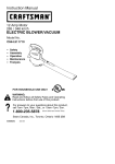
Operator's
Manual
CRAFTSMR
25cc/1.5 cu.in. 2-Cycle
215 MPH/470 CFM
GASOLINE
POWERED
BLOWER/VAC
Model No.
358.794772
•
•
Safety
Assembly
•
•
Operation
Maintenance
•
Parts List
•
Espa_ol,
p, 20
i
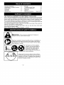
WARNING:
Read and follow all Safety Rules and Operating
Instructions before first use of this product.
For answers to your questions about this product:
Call 7 am-7 pm, Mon.-Sat., or 10 am-7 pm, Sun.
1-800-235-5878
Sears,
Roebuck
545167641
_.oors,,s,edaro
ceo,,o,
T,,'_
and Co., Hoffman
Rev. 4 4/16/08
BRW
Estates,
IL 60179
U.S.A.
Warranty Statement
Identification of Safety Symbols
Safety Rules
Assembly
Operation
Maintenance
2
2
3
5
8
11
Storage
Troubleshooting
Table
Emissions Statement
Parts List
Spanish
Parts and Ordering
13
14
15
17
20
Sack Cover
TWO YEAR FULL WARRANTY
ON CRAFTSMAN@
GAS BLOWER
When used and maintained according to the operator's manual, if this product fails
due to a defect in material or workmanship
within two (2) years from the date of purchase, return it to any Sears store, Sears Service Center, or other Craftsman outlet
in the United States for free repair (or replacement if repair proves impossible).
This warranty excludes spark plug and air cleaner, which are expendable parts that
can wear out from normal use in tess than two years.
This warranty applies for only 30 days from the date of purchase if this product is
used for commercial or rental purposes.
This warranty gives you specific legal rights, and you may also have other rights
which vary from state to state.
Sears, Roebuck and Co., Hoffman Estates, IL 60179
l
I&
I
improper use can cause serious injury.
I _WARNING:
This unit can be dangerous!
Careless
or
derstand and can follow all warnings and safety rules before
operating the unit. Failure to do so can result in serious injury.
Read your operator's manual carefully until you completely unSave operator's manual
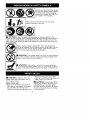
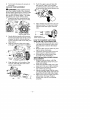
The blower can throw objects
violently. You can be blinded or
injured. Always wear hearing
protection and safety glasses
marked Z87. Always wear
heavy, long pants, long sleeves,
boots and gloves.
3%
J
Hazard zone for thrown objects. Keep children,
bystanders, and animals away from work area a
minimum of 30 feet (10 meters) when starting or
operating unit. Do not point blower nozzle in the
direction of people or pets.
-2-
_O
Do not wear jewelry, loose clothing,
or clothing with loosing hanging
straps,
etc. Theylength,
can
Secure ties,
hair tassels,
above shoulder
be caught in moving parts.
_
_
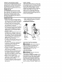
WARNING:
Stop the engine before opening the vacuum inlet door. The
engine must be stopped and the impeller blades no longer turning to avoid serious
injury from the rotating blades. Gently tilt the handle of the screwdriver toward the
back of the unit to release the latch while pulling up on the vacuum inlet cover with
our other hand.
When using the vacuum attachment, the unit is designed to
pick up dry material such as leaves, grass, small twigs, and bits
of paper< Do not vacuum stones, gravel, metal, broken glass,
etc., to avoid severe damage to the impeller.
_i WARNING:
Fire hazard< Never mix, pour, or store gasoline
or use the unit near a flame or sparks (including smoking, open
flames, or work that can cause sparks)<
WARNING:
The muffler is very hot during and after use.
Do not touch the muffler, muffler guard, or surrounding surfaces,
or allow combustible material such as dry grass or fuel to do so.
_WARNING:
• Restrict unit to users who understand and will follow all warnings and
safety rules in this manual.
Failure to follow all
Safety Rules and Precautions
sult in serious injury.
can re-
KNOW YOUR UNIT
• Read your operator's manual carefully unffl you completely understand
and can follow alt warnings and
safety rules before operating the unit.
-3-
WARNING:
Inspect area before
starting unit, Remove all debris and
hard objects such as rocks, glass,
wire, etc. that can ricochet, be thrown,
or otherwise cause injury or damage
during operation.
Use your unit as a blower for:
• Sweeping debris or grass clippings
from driveways, sidewalks, patios, etc.
• Blowing grass clippings, straw, or
leaves into piles, around joints, or between bricks.
Use your unit as a vacuum for:
• Picking up dry material such as
leaves, grass, small twigs, and bits of
paper.
• For best results during vacuum use,
operate your unit at high speed.
• Move slowly back and forth over the
material as you vacuum. Avoid forcing the unit into a pile of debris as
this can clog the unit,
• Keep the vacuum tube about an inch
above the ground for best results.
• Make sure the unit is properly assembled and in good operating condition.
• Do not fill fuel tank while engine is
running,
• Avoid spilling fuel or oil. Wipe up fuel
spills before starting engine.
• Move at least t0 feet (3 meters)
away from fuel and fueling site before starting engine.
• Always store gasoline in a container
approved for flammable liquids.
OPERATE
PLAN AHEAD
• Always wear eye protection when operating, servicing, or performing maintenance on unit. Wearing eye protection will help to prevent rocks or debris
from being blown or ricocheting into
eyes and face which can result in
blindness and/or serious injury. Eye
protection should be marked Z87.
• Always wear foot protection. Do not
go barefoot or wear sandals.
• Always wear respirator or face mask
when working with unit in dusty environments.
• Secure hair above shoulder length.
Secure or remove jewelry, loose
clothing, or clothing with loosely
hanging straps, ties, tassels, etc.
They can be caught in moving parts.
• Do not operate unit when you are
tired, ill, upset, or if you are under the
influence of alcohol, drugs, or medication.
• Keep children, bystanders, and animals away from work area a minimum of 30 feet (10 meters) when
starting or operating unit. Do not
point btower nozzte in the direction of
people or pets.
HANDLE FUEL WITH CAUTION, IT IS
HIGHLY FLAMMABLE
• Eliminate all sources of sparks or
flame (including smoking, open
flames, or work that can cause
sparks) in the areas where fuel is
mixed, poured, or stored.
• Mix and pour fuel in an outdoor area;
store fuel in a coot, dry, well ventilated
place; use an approved, marked container for all fuel purposes.
• Do not smoke while handling fuel or
while operating the unit.
-4-
YOUR UNIT SAFELY
WARNING:
Stop the engine before opening the vacuum inlet door. The
engine must be stopped and the impeller blades no longer turning to avoid serious injury from the rotating blades.
• Inspect unit before each use for
worn, loose, missing, or damaged
parts. Do not use until unit is in
proper working order.
• Keep outside surfaces free from oil
and fuel,
• Never start or run engine inside a
closed room, building or other unventilated area. Breathing exhaust
fumes can kill.
• To avoid static electricity shock, do
not wear rubber gloves or any other
insulated gloves while operating unit.
• Do not set unit on any surface except
a clean, hard area while engine is running. Debris such as gravel, sand,
dust, grass, etc. could be picked up by
the air intake and thrown out through
discharge opening, damaging unit,
property, or causing serious injury to
bystanders or operator.
• Avoid dangerous environments.
Do
not use in unventilated areas or
where explosive vapors or carbon
monoxide build up could be present.
• Do not overreach or use from unstable surfaces such as ladders, trees,
steep slopes, rooftops, etc. Keep firm
footing and balance at all times.
• Never place objects inside the
blower tubes; always direct the blowing debris away from people, animals, glass, and solid objects such
as trees, automobiles, walls, etc. The
force of air can cause rocks, dirt, or
sticks to be thrown or to ricochet
which can hurt people or animals,
break glass, or cause other damage.
• Never run unit without the proper
equipment attached. When using
your unit as a blower, always install
blower tubes. When using the optional vacuum kit, always install vacuum tubes and vacuum bag assembly. Make sure vacuum bag assembly is completely zipped.
• Check air intake opening, blower
tubes, and vacuum tubes frequently.
always with engine stopped and
spark plug disconnected.
Keep vents
and discharge tubes free of debris
which can accumulate and restrict
proper air flow.
• Never place any object in air intake
opening as this could restrict proper air
flow and cause damage to the unit.
• Never use for spreading chemicals,
fertilizers, or other substances which
may contain toxic materials.
• To avoid spreading fire, do not use
near leaf or brush fires, fireplaces,
barbecue pits. ashtrays, etc.
• Use only for jobs explained in this
manual,
MAINTAIN YOUR UNIT PROPERLY
_WARNING:
Disconnect spark
plug before performing maintenance
except for carburetor adjustments.
• Have all maintenance other than the
recommended
procedures described
in the operator's manual performed
by a Sears Service Center.
• Use only recommended
Craftsman
replacement parts; use of any other
parts may void your warranty and
cause damage to your unit.
• Empty fuel tank before storing the
unit. Use up fuel left in carburetor by
starting engine and letting it run until
it stops.
• Do not use any accessory or attachment other than those recommended
by manufacturer for use with your unit.
• Do not store the unit or fuel in a closed
area where fuel vapors can reach
CARTON CONTENTS
Check carton contents
lowing list,
Model 358.794772
• Blower
SAFETY NOTICE: Exposure to vibrations through prolonged use of gasoline powered hand tools could cause
blood vessel or nerve damage in the
fingers, hands, and joints of people
prone to circulation disorders or abnormal swelling. Prolonged use in cold
weather has been linked to blood vessel damage in otherwise healthy
people. If symptoms occur such as
numbness, pain, loss of strength,
change in skin color or texture, or toss
of feeling in the fingers, hands, or
joints, discontinue the use of this tool
and seek medical attention. An
antivibration system does not guarantee the avoidance of these problems.
Users who operate power tools on a
continual and regular basis must monitor closely their physical condition and
the condition of this tool.
SPECIAL NOTICE: This unit is
equipped with a temperature limiting
muffler and spark arresting screen
which meets the requirements of California Codes 4442 and 4443. All U.S.
forest land and the states of California,
Idaho. Maine, Minnesota, New Jersey,
Oregon, and Washington require by
law that many internal combustion engines be equipped with a spark arresting screen. Ifyou operate in a locale
where such regulations exist, you are
legally responsible for maintaining the
operating condition of these parts. Faiture to do so is a violation of the law.
Refer to the MAINTENANCE section for
information on maintenance of the
muffler and spark arresting screen.
• Lower vacuum tube
• 2-Cycle engine oil
NOTE: It is normal for the fuel filter to
rattle in the empty fuel tank.
ASSEMBLY
against the fop
Upper blower tube
Lower blower tube
High velocity
Elbow tube
sparks or an open flame from hot
water heaters, electric motors or
switches, fumaces, etc.
• Store in a dry area out of reach of
children.
WARNING:
Stop engine and be
sure the impeller blades have stopped
turning before opening the vacuum inlet door or attempting to insert or remove the vacuum tubes. The rotating
blades can cause serious injury.
nozzle
Vacuum bag
Upper vacuum tube
-5-
WARNING:
If you receive your
unit assembled, repeat all steps to ensure your unit is properly assembled
and all fasteners are secure.
A standard screwdriver is required
for assembly.
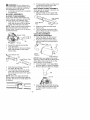
BLOWER
ASSEMBLY
BLOWER TUBE ASSEMBLY
If you have already assembled your
unit for use as a vacuum, remove the
vacuum tubes and collection bag.
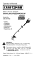
1. Align the rib on the upper blower
tube with the groove in the blower
outlet; slide the tube into place.
NOTE: Knob must be loose enough to
allow blower tube to be inserted in
biower outlet. Loosen knob by turning
counterclockwise.
_
_
v_s:_:-_"
2.
3.
B_owerOutlet
_'
\" Rib
Groove
Secure the tube by turning the
knob clockwise.
Align the slots on the lower blower
tube with the tabs on the upper
blower tube.
6.
To remove the tubes, turn the knob
counterclockwise
to loosen the
tubes; remove the tubes.
HIGH-SPEED
NOZZLE ASSEMBLY
When greater air speed is desired, use
the high-speed nozzle.
1. Align the slots on the nozzle with
the tabs on the lower btower tube.
High-Speed
Nozz{e
i
Lower Blower
Tube
2.
Slide the nozzle onto the lower
blower tube.
3. Turn the nozzle clockwise untit a
click is felt to secure the nozzle to
the lower blower tube.
VACUUM
ASSEMBLY
VACUUM BAG ASSEMBLY
1. Open the zipper on the vacuum
bag and insert the elbow tube.
2. Push the small end of the elbow
tube through the small opening in
the bag.
Elbow Tube
Rib
Opening
Tab
Lower Blower Tube
'_
Small Opening
NOTE: Make sure edge of the small
opening is flush against the flared area
of the elbow tube, and the rib on the
elbow tube is on the bottom.
3.
4.
5.
Slide the lower blower tube onto
the upper blower tube.
Turn the lower blower tube clockwise until a click is felt to secure
the lower blower tube to the upper
blower tube.
4.
Close the zipper on file bag. Make
sure the zipper is closed completely.
Remove blower tubes from engine.
NOTE: When the upper and lower
blower tubes are assembled together
properly, the arrows on both tubes witt
be aligned.
5. Insert the elbow tube into the blower outlet. Make sure elbow tube rib
is aligned with the biower outlet
groove.
6. Turnknob
clockwise
tosecure
elbowtube.
VACUUM
TUBE
ASSEMBLY
_WARNING:Stopengine
andbe
suretheimpeller
blades
have
stopped
turning
before
opening
thevacuum
inlet
doororattempting
toinsert
orremove
thevacuum
orblower
tubes.
Therotatingblades
cancause
serious
injury.
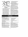
1. Insert
thetipofascrewdriver
into
the latch area of the vacuum
LatchA_ea q Blower
Vacuum
2.
3.
Push the upper vacuum tube into
the vacuum inlet. Tum the tube
counterclockwise until a click is felt
to secure the tube to the blower unit.
6.
Align slanted end of lower vacuum
tube as shown. Firmly push lower
vacuum tube into upper vacuum
tube.
inlet.
Inlet Cover
Gently tilt the handle of the screwdriver toward the front of the unit to
release the latch while pulling up
on the vacuum inlet cover with your
other hand.
Hold the vacuum inlet cover open
until upper vacuum tube is installed.
Vacuum
Inlet
Cover
/
/
Inlet
4.
5.
Align the tabs on the inside of the
vacuum inlet with the slots in the
upper vacuum tube.
Slanted end of
HOW TO CONVERT UNIT FROM
VACUUM USE TO BLOWER USE
1. Remove the elbow tube and vacuum bag by turning the knob counterclockwise to loosen the elbow
tube.
2. Remove the vacuum tubes by turning the tubes clockwise.
3, Close the vacuum inlet cover and
make sure it is latched closed.
4. Reinstall the blower tubes (see
BLOWER TUBE ASSEMBLY).
VACUUM BAG SHOULDER STRAP
ADJUSTMENT
1. Hold the unit as shown with the
2.
3.
4.
5.
({
Tab
sl0t
"-'_-L
-7-
muffler side facing away from your
body and clothes.
Pass the shoulder strap over your
head and onto your right shoulder.
Extend your left arm toward the
rear of the vacuum bag.
Adjust shoulder strap unffl the vacuum bag/shoulder strap seam lies between your thumb and index finger.
Make sure air flows freely from the
elbow tube into bag. If bag is
kinked, the unit will not operate
properly.
SHOULDER STRAP ATTACHMENT
(optional acce88ory #71-85783)
1. Pass the shoulder strap over your
head and onto your left shoulder.
2. Snap the hook onto the retainer
(see following illustration).
BLOWER
USE
VACUUM
USE
Retainer
KNOW YOUR BLOWER
READ THiS OPERATOR'S MANUAL AND SAFETY RULES BEFORE OPERATING YOUR
UNIT Compare the illustrations with your unit to familiarize yourself with the location
of the vadous controls and adjustments. Save this manual for _ture reference.
MULCHING BLADES
Your blower is equipped with mulching blades as a standard feature. When using
the vacuum attachment, the mulching blades automatically reduce debris at a
ratio of up to 16:1.
STOP SWITCH
The STOP switch is used to stop the
engine. To stop the engine, push and
hold the STOP switch in the STOP position until the engine stops,
THROTTLE TRIGGER
The THROTTLE TRIGGER is used to select the desired engine speed,
-8-
THROTTLE
POSITION LEVER
The THROTTLE POSITION LEVER is designed to allow setting engine speed
during blower use only. To avoid causing damage to the unit, DO NOT attempt to use the throttle position lever
during vacuum use.
PRIMER BULB
The PRIMER BULB removes air from
the carburetor and fuel lines and flits
START LEVER
The START LEVER helps to supply fuel
to the engine to aid in starting. Activate
the starting system by moving the start
lever to the START position. DO NOT
squeeze the throttle trigger until the
engine has started and runs. After the
engine starts, allow the engine to
warm-up t 0-15 seconds, then fully
squeeze the throttle trigger to deactivate the starting system (start tever returns to RUN position).
them with fuel This allows you to start
the engine with fewer pulls on the
starter rope. Activate primer bulb by
pressing it and allowing it to return to
its original position.
OPERATING TIPS
• While vacuuming or blowing debris,
hold the unit with the muffler side fac-
•
•
•
•
•
•
ing away from your body and cIothes
(see OPERATING POSITION below).
To reduce the risk of hearing loss
associated with sound level(s), hearing protection is required.
To reduce the risk of injury associated
with contacting rotating parts, stop the
engine before installing or removing
attachments. Do not operate without
guard(s) in place.
Operate power equipment only at reasonable hours-not eady in the morning or late at night when people might
be disturbed. Compty with times listed
in local ordinances. Usual recommendations are 9:00 a.m. to 5:00 p.m.,
Monday though Saturday.
To reduce noise levels, timit the number of pieces of equipment used at
any one time.
To reduce noise levels, operate power blowers at the lowest possible
throttle speed to do the job.
Use rakes and brooms to loosen
• After using blowers and other equipment, CLEAN UP! Dispose of debris
in trash receptacles.
OPERATING POSITION
Blower
BEFORE
_
Vacuum
STARTING
WARNING:
ENGINE
Be sure to read the
fuel information in the safety rules
before you begin. If you do not
understand the safety rules, do not
attempt to fuel your unit. Call
1-800-235-5878.
debris before btowing.
• In dusty conditions, siightly dampen
surfaces or use a mister attachment
when water is available.
• Conserve water by using power blowers instead of hoses for many lawn
and garden applications, including
areas such as gutters, screens, patios,
grills, porches, and gardens.
• Watch out for children, pets, open
windows, or freshly washed cars.
Blow debris away safely.
• Use the fult blower nozzle extension
so the air stream can work close to
the ground.
-9-
FUELING
ENGINE
WARNING:
Remove fuel cap
slowly when refueling.
This engine is certified to operate on unleaded gasoline. Before operation, gasoline must be mixed with a good quality
synthetic 2-cycte air-cooled engine oil.
We recommend Craftsman brand synthetic oil. Mix gasoline and oil at a ratio
of 40:1. A 40:1 ratio is obtained by mixing 3.2 ounces of oil with 1 gatlon of un-
leaded gasoline. Included with this blower is a 3.2 ounce container of oil. Pour
the entire contents of this container into
1 gallon of gasoline to achieve the proper fuel mixture. DO NOT USE automotive
oil or boat oil. These oils will cause engine damage. When mixing fuel, follow
instructions printed on container. Once
oil is added to gasoline, shake container
momentarily to assure that the fuel is
thoroughly mixed. Always read and follow the safety rules relating to f_el before fueling your unit.
IMPORTANT
Experience indicates that alcohol
blended fuels (called gasohol or using
ethanol or methanol) can attract moisture which leads to separation and
formation of acids during storage.
Acidic gas can damage the fuel system of an engine while in storage.
To avoid engine problems, empty the
fuel system before storage for 30 days
or longer. Drain the gas tank, start the
engine and let it run until the fuel lines
and carburetor are empty. Use fresh
fuel
next
season,
Never
use
engine
or
carburetor cleaner products in the fuel
tank or permanent damage may occur.
Fuel stabilizer is an acceptable alternative in minimizing the formation of
fuel gum deposits during storage.
Craftsman brand oil is already blended
with fuel stabilizer. See the STORAGE
section for additional information.
HOW TO STOP YOUR ENGINE
• Release the throttle trigger.
• Push and hold the STOP switch in the
STOP position until the engine stops.
HOW TO START YOUR ENGINE
_WARNING:
STARTING POSITION
Blower
WARNING:
When starting engine,
hold the unit as illustrated, Do not set
unit on any surface except a clean, hard
area when starting engine or while engine is running. Debris such as gravel,
sand, dust, grass, etc, could be picked
up by the air intake and thrown out
through the discharge opening, damaging the unit or property, or causing serious injury to bystanders or the operator.
STARTING A COLD ENGINE (or
warm engine after running out of fuel)
1, Move the throttle position lever
(cruise control) to the idle position,
Throttle
Position
Lever
Control)
You MUST make sure
the tubes are secure before using the
unit.
• Fuel engine. Move at least 10 feet (3
meters) away from the fueling site.
• Hold the unit in the starting position
as shown. Make sure the blower end
is directed away from people, animals, glass, and solid objects.
-10-
2.
3.
Slowly press the primer bulb 6 times.
Move the start tever to the START
position,
Starter
Handle
6.
\
Start/_
Lever
Primer /
Bulb
4.
5.
This unit has the Sim-pul'
starting
system. You do not have to pull the
starter rope handle sharply or
briskly. Pult starter rope handle 5
times with a controlled and steady
motion (no more than 3 times
above 90F). If engine starts and
runs prior to 5 pulls, allow engine to
run for 5 seconds; then, fully
squeeze the throttle trigger to disengage the starting system (start
lever returns to RUN position).
Steps 5 and 6 are not necessary.
Fully squeeze the throttle trigger to
disengage the starting system (start
lever returns to RUN position).
CUSTOMER
Pull starter rope handle with a controlled and steady motion while
squeezing throttle trigger until
engine starts and runs.
STARTING A WARM ENGINE
1. Squeeze and bold the tbrotfle trigger.
2. Pull starter rope handle with a controlled and steady motion while
squeezing throttle trigger until engine starts and runs.
NOTE: Normally, the warm starting
procedure can be used within 5-t0
minutes after the unit is turned off. If
the unit sits for more than 10 minutes
without being used, it witt be necessary
to start the unit by following the steps
under STARTING A COLD ENGINE or following the starting instruction steps
shown on the unit.
STARTING A FLOODED ENGINE
Flooded engines can be started by moving the start lever to the RUN position
and fully squeezing the throttle trigger.
Pull the starter handle repeatedly while
squeezing throttle trigger until engine
starts and runs. This could require pulling the starter handle many times, depending on how badly the unit is
flooded. If the unit still doesn't start, refer to the TROUBLESHOOTING TABLE or
call 1-800-235-5878.
RESPONSIBILITIES
WARNING:
Disconnect the spark plug before performing maintenance,
service, or adjustments.
CARE & MAINTENANCE TASK
WHEN TO PERFORM
Before each use
Check for loose fasteners and parts
Check for damaged
Before each use
After each use
or worn parts
Inspect and clean unit and labels
Clean air filter
Replace
spark plug
Replace
fuel filter
Check muffler mounting
Every 5 hours of operation
Yearly
Yearly
screws
_WARNING:
Yearly
plug before performing maintenance
accessing movable parts.
_WARNING:
Stop engine and be
sure the impeller blades have stopped
turning before opening the vacuum intet door or attempting to insert or remove the vacuum or blower tubes.
The rotating blades can cause serious
injury. Always disconnect the spark
G EN ERAL RECOMM ENDATIONS
The warranty on this unit does not cover items that have been subjected to
operator abuse or negligence. To receive fult value from the warranty, the
operator must maintain unit as instructed in this manual. Various adjustments
will need to be made periodically to
properly maintain your unit.
Avoid touching muffler unless engine and muffler are cold.
A hot muffler can cause serious burns.
-11
-
or
CHECK FOR LOOSE
FASTENERS AND PARTS
• Muffler
• Spark Plug Boot
• Air Filter
• Housing Screws
CHECK FOR DAMAGED
OR
WORN PARTS
Contact Sears Service Center for replacement of damaged or worn parts.
• Fuel Tank - Do not use unit if fuel tank
shows signs of damage or leaks.
• Vacuum Bag - Do not use vacuum
bag if it is torn or damaged.
INSPECT AND CLEAN UNIT
AND LABELS
• After each use, inspect complete unit
for loose or damaged parts. Clean
the unit using a damp cloth with a
mild detergent.
• Wipe off unit with a clean dry cloth.
CLEAN AIR FILTER
A dirty air filter decreases engine performance and increases fuel consumption and harmful emissions. Always
clean after every 5 hours of operation.
REPLACE SPARK PLUG
Replace spark plug each year to ensure
the engine starts easier and runs better.
Set spark plug gap at 0.025 inch. Ignition timing is fixed, nonadjustable.
1. Twist, then pull off spark plug boot.
2. Remove spark plug from cylinder
and discard.
3. Replace with Champion RCJ-6Y
spark plug and tighten securely
with a 3/4 inch socket wrench.
4. Reinstall the spark plug boot.
REPLACE FUEL FILTER
To replace fuel filter, drain unit by running it dry of fuel, then remove fuel
cap/retainer assembly from tank. Pull
filter from tank and remove it from the
fuel line. Install new fuel filter on fuet
line; reinstall parts.
L
Fuel F!lter_
_
Fuel Line
Button
Air Filter
Air Filter
CHECK MUFFLER MOUNTING
SCREWS
Once each year, ensure muffler
mounting screws are secure and tightened properly to prevent damage.
Cover
Cleaning the air filter:
1. Clean the cover and the area
around it to keep debris from falling
into the carburetor chamber when
the cover is removed.
NOTE: Move start lever to RUN position before opening air filter cover.
2. Open air filter cover by pushing
button (see illustration). Remove
air filter.
NOTE: Do not clean filter in gasoline
or other flammable solvent. Doing so
can create a fire hazard or produce
harmfut evaporative emissions.
3. Wash the filter in soap and water,
4. Allow filter to dry,
5. Apply a few drops of oit to the filter;
squeeze filter to distribute oil.
6. Replace parts.
-12-
--
Muffler
Mounting Screw
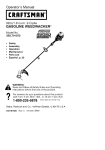
INSPECT MUFFLER AND SPARK
ARRESTING SCREEN
WARNING:
The muffler on this
product contains chemicals known to
the State of California to cause cancer.
As the unit is used, carbon deposits
build up on the muffler and spark arresting screen, and must be removed
to avoid creating a fire hazard or affecting engine performance.
,
Spark
Arresting
Screen
Screws
Replace the spark arresting screen every 50 hours of operation or if any damage or breaks in file screen are noted.
NOTE: Do not attempt to clean the
spark arresting screen.
1. Remove 3 screws from muffler cover. Remove muffler cover.
2. Loosen and remove 4 screws from
the muffler hood.
Remove the muffler hood and spark
arresting screen.
4. Install new spark arresting screen.
5. Reinstall muffter hood and 4
screws. Tighten screws securely.
6. Reinstall muffter cover and 3
screws. Tighten securely.
NOTE: If any part of the muffler is
cracked, broken or damaged, we recommend that the muffler be replaced.
CARBURETOR
ADJUSTMENT
The carburetor has been carefully set
at the factory. Adjustments may be
necessary if you notice any of the following conditions:
• Engine will not idle when the throttle is
released.
Idle Speed Adjustment
Allow engine to idle. Adjust speed until
engine runs without stalling (idle speed
too slow).
• Turn idle speed screw clockwise to
increase engine speed if engine
stalls or dies.
• Turn idle speed screw counterclockwise to decrease engine speed.
3.
_WARNING:
Perform the following
steps after each use:
• Allow engine to cool, and secure the
unit before storing or transporting.
• Store unit and fuel in awett ventilated area where fuel vapors cannot
reach sparks or open flames from
water heaters, electric motors or
switches, furnaces, etc.
• Store unit with all guards in place.
Position unit so that any sharp object
cannot accidentally cause injury.
• Store unit and fuel well out of the
reach of children.
SEASONAL
STORAGE
Prepare unit for storage at end of season or if it wilt not be used for 30 days
or more. If your unit is to be stored for
a period of time:
• Clean the entire unit before lengthy
storage.
• Store in a clean dry area.
• Lightly oil external metal surfaces.
-13-
If you require further assistance or are
unsure about performing this procedure, contact your Sears Service Center or call our customer assistance
help line at 1-800-235-5878.
FUEL SYSTEM
Empty the fuel system before storage for
30 days or longer. Drain tile gas tank,
start the engine and let it run until the
f_el lines and carburetor are empty. Use
fresh fiJel next season. Under FUELING
ENGINE in the OPERATION section of this
manual, see message labeled
IMPORTANT regarding file use of gasohol in your engine.
Fuel stabilizer is an acceptable altamative in minimizing the formation of fuel
gum deposits during storage. Add stabilizer to gasoline in fuel tank or fuel storage container. Follow the mix instructions found on stabilizer container. Run
engine at least 3 minutes after adding
stabilizer.
Craftsman 40:1,2-cycle
engine
cooled) is already blended with
stabilizer. If you do not use this
oil, you can add a fuel stabilizer
fuel tank.
oil (air
fuel
Sears
to your
ENGINE
• Remove spark plug and pour 1 teaspoon of 40:1,2-cycle
engine oit (air
cooled) through the spark plug opening. Slowly pull the starter rope 8 to
10 times to distribute oil.
• Replace spark plug with new one of
recommended
type and heat range.
• Clean air filter.
TROUBLESHOOTING
• Check entire unit for loose screws,
nuts, and bolts. Replace any damaged, broken, or worn parts.
• At the beginning of the next season,
use only fresh fuel having the proper
gasoline to oil ratio.
OTHER
• Do not store gasoline from one season to another.
• Replace your gasoline can if it starts
to rust.
TABLE
WARNING:
Always stop unit and disconnect spark plug before per[orming any of the recommended remedies below other than remedies that require
operation
of the unit.
TROUBLE
i CAUSE
Engine will not
start,
;; 1. Engine flooded.
REMEDY
;; 2. Fuel tank empty.
;; 3. Spark p_ug not firing.
4. Fuel not reaching
1. See "Starting a Flooded Engine '+
in Operation section
2. Fill tank with correct fue{ mixture
J3. Install new spark plug.
4. Check for dirty fuel filter; replace.
carburetor.
;; 5. Compression
Engine will not
idle properly,
Engine wilt not
accelerate,
lacks power, or
dies under a
load.
Check
forreptace.
kinked or split fuel line;
repair or
5. Contact Sears Service (see back cover).
low
1. Fuel not reaching
carburetor.
2. Carburetor requires
adjustment.
;;3. Crankshaft seals worn
4. Compression
low.
I1. Air filter dirty.
2. Fuel not reaching
carburetor.
3. Spark p_ug fouled.
4. Carburetor requires
adjustment.
5. Carbon build up.
i 6. Compression
low.
Engine smokes
excessively.
Engine runs hot.
i1
i2
J
3
4
:
1.
1. Check for dirty fuel filter; replace.
Check for kinked or split fuel line;
repair or replace.
2. Contact Sears Service (see back cover).
3. Contact
4. Contact
Air filter dirty.
Carburetor requires
adjustment.
Fuel mixture incorrect.
2. Spark plug incorrect.
3. Carburetor requires
adjustment.
4. Carbon buitd up
Sears
Sears
Service (see back cover
Service (see back covet
::1. Adjust choke.
2. Empty fuel tank and refill with
correct rue mxture.
3. Clean or replace air filter.
4. Contact Sears Service (see back cover)
il.
i
i2.
i3.
t
See 'Fueling Engine" in Operation
section
Replace with correct spark plug.
Contact Sears Service (see back cover)
i4. Contact
-14-
(see back cover).
(see back cover).
;;1. Clean or replace air filter.
2. Check for dirty fuel filter; replace.
Check for kinked or split fuel line;
repair or replace.
3. Clean or replace spark plug
;; and re-gap.
4. Contact Sears Service (see back covet
. Contact
;6. Contact
Choke partially on.
Fuel mixture incorrect.
Sears Service
Sears Service
Sears
Service (see back cover)
YOUR WARRANTY RIGHTS AND OBLIGATIONS: The U.S. Environmental
Protection Agency/California Air Resources Board and Sears, Roebuck and
Co., U.S.A., are pleased to explain tile
emissions control system warranty on
your year 2007 and later small off-road
engine. In California, all small off-road
engines must be designed, built, and
equipped to meet the State's stringent
anti-smog standards. Sears must warrant the emission control system on your
small off-road engine for the periods of
time listed below provided there has
been no abuse, neglect, or improper
maintenance of your small off-road engine. Your emission control system includes parts such as the carburetor, file
ignition system and the fuel tank (California only). Where a warrantable condition
exists, Sears will repair your small offroad engine engine at no cost to you.
Expenses covered under warranty include diagnosis, parts and labor.
MANUFACTURER'S
WARRANTY
COVERAGE: If any emissions related
part on your engine (as listed under
Emissions Controt Warranty Parts List) is
defective or a defect in the materials or
workmanship of file engine causes the
failure of such an emission related part,
the part will be repaired or replaced by
Sears.
OWNER'S WARRANTY RESPONSIBILITIES: As file small off-road engine
engine owner, you are responsible for
the performance of the required maintenance listed in your operator's manual.
Sears recommends that you retain all
receipts covering maintenance on your
small off-road engine, but Sears cannot
deny warranty solely for the tack of receipts or for your failure to ensure the
performance of all scheduled maintenance. As the small off-road engine engine owner, you should be aware that
Sears may deny you warranty coverage
if your small off-road engine engine or a
part of it has failed due to abuse, neglect, improper maintenance, unapproved modifications, or the use of parts
not made or approved by the original
equipment manufacturer. You are responsible for presenting your small offroad engine to a Sears authorized repair
center as soon as a problem exists.
-15-
Warranty repairs should be completed in
a reasonable amount of time, not to exceed 30 days. ff you have any questions regarding your warranty rights and
responsibilities, you should contact your
nearest authorized service center or call
Sears at 1-800-469-4663.
WARRANTY
COMMENCEMENT
DATE: The warranty period begins on the date the smatl
off-road engine is purchased. LENGTH
OF COVERAGE: This warranty shall be
for a period of two years from the initial
date of purchase. WHAT IS COVERED: REPAIR OR REPLACEMENT
OF PARTS. Repair or repIacement of
any warranted part will be performed at
no charge to the owner at an approved
Sears Service Center. If you have any
questions regarding your warranty rights
and responsibilities, you should contact
your nearest authorized service center
or call Sears at 1-800-469-4663. WARRANTY PERIOD: Any warranted part
which is not scheduled for replacement
as required maintenance, or which is
scheduled only for regular inspection to
the effect of "repair or replace as necessary" shall be warranted for 2 years. Any
warranted part which is scheduled for
replacement as required maintenance
shall be warranted for the period of time
up to the first scheduled replacement
point for that part. DIAGNOSIS: The
owner shall not be charged for diagnostic labor which leads to the determination that a warranted part is defective if
the diagnostic work is performed at an
approved Sears Service Center. CONSEQUENTIAL DAMAGES: Sears may
be liable for damages to other engine
components caused by the failure of a
warranted part still under warranty.
WHAT IS NOT COVERED: All failures
caused by abuse, neglect, or improper
maintenance are not covered. ADD-ON
OR MODIFIED PARTS: The use of
add-on or modified parts can be
grounds for disallowing a warranty claim.
Sears is not liable to cover failures of
warranted parts caused by the use of
add-on or modified parts. HOW TO
FILE A CLAIM: If you have any questions regarding your warranty rights and
responsibilities, you should contact your
nearest authorized service center or calt
Sears at 1-800-469-4663.
WHERE TO GET WARRANTY SERVICE: Warranty services or repairs shall
be provided at all Sears Service Centers. Call 1-800-469-4663.
MAINTENANCE, REPLACEMENT
AND REPAIR OF EMISSION RELATED PARTS: Any Sears approved
replacement part used in the performance of any warranty maintenance or
repair on emission related parts will be
provided without charge to the owner if
the part is under warranty.
EMISSION CONTROL WARRANTY
PARTS LIST: Carburetor, Ignition System: Spark Plug (covered up to maintenance schedule), Ignition Module, Muffler including Catalyst, Fuel Tank (California only). MAINTENANCE STATEMENT: The owner is responsible for the
performance of all required maintenance
as defined in tile operator's manual.
The information on the product labet indicates which standard your engine is certified.
Example: (Year) EPA Phase 1 or Phase 2 and/or CALIFORNbA.
41
This engine is certified to be emissions
[]
Moderate
[]
Intermediate
[]
Extended
1 61
compliant
(50 hours)
(t25 hours)
(300 hours)
-16-
1 81
I
for the following
use:
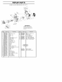
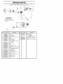
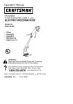
REPAIR
PARTS
SEARS GAS BLOWER MODEL 358.794772
2_
_&WARNING
A_ repair8
mahltenanee
adjustments
and
ilot descdbed
in
the Operatol's
Manual must _e
performed by Qualified Selvice
Re 5onne_
Ref
1
2.
3
4
5
6
7
6.
9
10
11
12.
13
14
15
16
17
18.
19.
20
21
22.
23
24
25
26
27
28.
29.
30
31
32.
33
34
35
Part
No.
530015814
545150502
530015880
545134001
545099101
545052401
545052501
545050407
545054901
545152901
545050416
545107101
545138601
545081830
545128201
545137701
545099001
545116201
530015814
545111501
545173101
545081867
545144901
545138801
530016406
530015814
545139001
545115601
545144501
530015940
545152501
545120701
545113601
545113701
530015197
Description
Screw
Assy
Engine Cover
Screw
Shield
Baffle
Baffle
Hub
Spdng
Pulley
Kit Starter Pulley (Incl
Spdng
Starter
Handle
Starter
Kit
Rope
Tube
Sta_tel rope
Handle
RH
Ref
6,7)
Part NO.
Description
36
37
38
39
530015386
545161608
545138501
545100401
Screw
Assy
Scroll RH (Incl
Handle
Vac
40
41
42
43
44
530095646
530069247
530069216
530057973
530016445
Assy
Fuel tank
(Incl 40,41,42,43)
Assy
Fuel Pickup
Kit
Fuelline
(curb/purge)
Kit
Fuelline
(tanWpurge)
Assy
Fuel Cap with retainer
Screw
Fueltank
retainer
545167641
Operator
545001245
545042802
Decal
Decal
Kit
Switch (Incl. 15)
Protector
Switch
Gmmmet
Beadng
Locknut
Screw
Rachet
Cruise Control
Washer
Wave
Kit
Cmise control(Inc119,20,21)
Tdgger
Throttle
Handle
LH
Scsew
Screw
Dool
Vac
Spdng
Vac door
Knob
Blower tube
Screw
Handle vac
Assy
Scroll LH (Incl
Blade
Mulch
Assy
Impeller
Spacer
Flywheel
Nut
Slower Knob
27,28)
Manual
Warning
Start Instruction
17)
REPAIR
PARTS
SEARS GAS BLOWER MODEL 358.794772
/
,t_WARNING
AI_ lepairs adjustment3
and
maintenance
not desodbe_l in
the Ope_ato's
Manua_ must be
performer1 by Qualified Se vice
Personnel
Ref.
Part
No.
1
2
3
4
5
6
7
8
g
10
11
545090001
530015241
545081845
530058982
545081832
545115301
530015953
Champion
545084901
545115501
545081857
12
13
14
15
16
17
18
19
20
21
545157104
545139301
530016429
545146501
545139201
530058709
545081832
530016441
545081832
545081854
22
23
24
25
26
27
25
29
30
31
32
33
530012472
530015162
545081865
545158001
530016357
545127601
545081832
530015828
530054115
530015941
530055728
530019254
R_.
Description
Assy
Mufflel (Incl 2,3,4,5)
Screw
Kit Spark Screen
Bolt M uffle_
Gasket
Mufflel (gasket kit)
Cylinder
Bolt
Spark plug (RCJ 6Y)
Adapter
Calb
Linkage
ThmRle
Kit Carb Assy(C1UW43B)
(Incl
12,17)
Lever
Choke
Base
ASbox
Screw
Filter
Cover
A8 box fiker
Bulb
Purge
O dng (Carb/Adapter)(gasket
Screw
O Ring (AdapteriCyk)(gasket
Kit Piston/Connecting
Rod
(Incl 22,23,24)
Ring
Piston
Retainer
Wdst Pin
530032125
530012582
35
545102102
37.
38
39.
40
545081832
530057954
530018388
545081832
kil
kit
Kit Assy Connecting
Rod
Module
Ignition
Screw
Assy
WSe Harness
O dng seal
Crankcase(kit)
Washer
Assy
Flywheel
Retainer
Clenkshaft
Bearing
Seal
Pert No.
34
35
Outel
18
Descrkotion
Beadng
Inner
Assy
Cmnkcase
(Incl 32,33,34)
Assy
CmnkcaseiCrankshaft
(Incl 31,35)
Q Ring (Rear plug)(gasket
Assy
Rear Plug (Incl 37)
Sclew
Kit
Gesket
(Incl
5,18,20,28,3;
kit)
REPAIR
PARTS
SEARS GAS BLOWER MODEL 358.794772
/
_
i
\"C
.........
i
7
Ref.
Part No
Description
1
2.
3
545099401
530095589
545139501
Tube
Tube
Tube
Uppe_ vac
Lowel vac
J
4
5
8
7
530095564
545138001
545138101
545151201
Assy
Vuc bag
Tube
Uppe_ Blower
Tube
Lowe_ Blower
Nozzle
High Speed