1
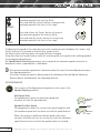
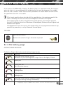
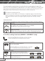
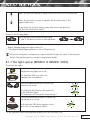
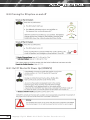
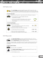
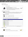
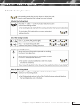
USER MANUAL
Netti Mobile
This product conforms to 93/42/EEC for medical products.
CONTENTS
1. INTRODUCTION 5
1.1 Areas of use/indications for Netti Mobile 6
1.2 Contraindications6
1.3 Quality and durability6
1.4 The environment and waste disposal
6
1.5 Information for re-use7
1.6 About this manual
7
1.7 Netti Mobile models
8
1.8 Vital measures
9
2. QUICK REFERENCE 10
3. ELECTROMAGNETIC INTERFERENCE AND WARNINGS
11
4. DESCRIPTION 13
14
5. FEATURES OF Netti Mobile
6. ACCESSORIES15
6.1 Assembly of Hip-Belt
17
6.1 Assembly of head support
17
7. ASSEMBLING AND ADJUSTMENT19
7.1 Unpacking19
7.2 Backrest19
7.3 Seat depth adjustment at the rear 20
7.4 Seat depth adjustment in front 20
7.5 Anti tip
20
7.6 Seat cushion
20
7.7 Backrest cushion
21
7.8 Adjusting velcro back 21
7.9 Foot supports
21
7.10 Arm support
25
7.11 Control unit position
26
7.12 Seat angle/tilt
26
7.13 Back rest angle
26
7.14 Free wheel levers
26
7.15 Fuse 27
7.16 Storage & Transport
27
7.17 Transfer
28
2
Language: English Model: Netti Mobile Version: December 2013 (3)
8. Netti Mobile ELECTRONICS
29
8.1 Shark power module and control unit 29
8.1.1 Turning the Netti Mobile on and off 31
8.1.2 Out of neutral at power up (OONAPU) 31
8.1.3 Mobile lock
32
8.1.4 Driving 33
8.1.5 The battery gauge
35
8.1.6 The seating functions (REMD11 & REMD21 only)
36
8.1.7 The light system (REMD21 & REMD31 ONLY)
37
8.1.8 Attendant mode
38
8.1.9 Troubleshooting Shark
39
8.2 Dynamic DX2 control system with DX2-REM420 LED
master remoteand control unit
41
8.2.0 Turning the DX system on and off 42
8.2.1 Out Of Neutral At Power Up (OONAPU)
42
8.2.2 System lock
43
8.2.3 Sleep mode
43
8.2.4 Driving
44
8.2.4.1 The joystick44
8.2.4.2 The drive profile
44
8.2.5 The horn
44
8.2.6 The seating functions
45
8.2.6.1 Available seating functions
46
8.2.7 The lights
46
8.2.8 The battery gauge
47
8.2.8.1 Battery charge indication
47
8.2.8.2 Other indications
47
8.2.9 The Fault indicator LED
48
8.2.9.1 ‘Service due’ indication
48
8.2.9.2 Fault indication
48
8.2.9.3 Flash codes
59
8.2.10 Attendant mode
51
8.2.11 Operation by external DX modules
51
8.3 Troubleshooting DX2
52
9. DRIVING TECHNIQUES
55
9.1 Driving your chair
55
9.2 To begin 55
9.3 Safe driving
55
9.4 Indoor/outdoor driving 55
Language: English Model: Netti Mobile Version: December 2013 (3)
3
9.5 Chair operation on surfaces that require special care
9.6 Chair response
9.7 Steep slopes
55
56
56
10. BATTERIES & CHARGING56
10.1 Battery charging
56
10.2 Drive inhibit configuration58
10.3 Replacing batteries
58
11. MAINTENANCE 59
11.1 El. components 59
11.2 Frame & seating system
60
12. TESTS & WARRANTY
62
12.1 Tests 62
12.2 Guarantee62
12.3 Claim
62
12.4 Spare part guarantee63
12.5 Special adjustment/adaptation
63
12.6 Combination with other products
63 12.7 Service and repair
63
13. MEASURES & WEIGHT
4
Language: English Model: Netti Mobile Version: December 2013 (3)
64
1. INTRODUCTION
Netti Mobile is an electrical comfort
wheelchair meant for both indoor and outdoor use. It is tested to DIN EN
12184:2009. The tests were carried out
by TÜV SÜD Product Service GmbH in
Germany.
In Alu Rehab we believe that wheelchairs
should be chosen based on a thorough
assessment focusing on the needs of the
user and demands from the environment.
Therefore it is important to know about
the possibilities and restrictions of the
wheelchair. Netti Mobile is an electrical
class B wheelchair designed for users with the
need for comfort and relief. The
combination between the seating system
and the ergonomical solutions in the frame
construction, offers many possibilities for
adaptation and adjustments.
The wheelchair is constructed for indoor and
outdoor use, and offers the possibility to
vary the sitting position.
Max user weight: 140 kg.
Specifications varies between
countries.
Language: English Model: Netti Mobile Version: December 2013 (3)
5
1.1 Areas of use/indications for Netti Mobile
Netti Mobile is an electrical comfort
wheelchair for partially immobile persons
with physical and/or mental disabilities.
These disabilities may have multiple causes.
Netti Mobile has an adjustable seat and back
angle, thus facilitating for the user change of
position, mobilisation or posture correction
(stabilisation), wherever the following
functional impediments with their multiple
possible causes are present:
• limited or lacking mobility
• limited or lacking muscle power
• limited movement range
• lacking or limited trunk and body stability
• hemiplegia
• rheumatic-type disorders
• craniocerebral injuries
• amputations
• other neurological or geriatric disorders.
1.2 Contraindications
Netti Mobile is not suited for persons who
due to reduced cognitive function do not
understand how to operate the electronical
functions of the wheelchair.
1.3 Quality and durability
The Netti Mobile wheelchair is tested
at TÜV SÜD Product Service GmbH
in Germany, following the European
Standard DIN EN 12184:2009. As
manufacturer, Alu Rehab A.S evaluates
the test to be equal to 5-6 years of
normal use of the chair. The disability
of the user as well as the level of
maintenance done foremost decides the
durability of the wheelchair. Thus, the durability will vary depending on these
two factors.
1.4 The environment and waste disposal
Alu Rehab and its suppliers wish to
protect the environment.
This means:
• That we avoid using
environmentally harmful
substances and processes
to the greatest extent possible.
• That Alu Rehab’s products are ensured a long service life and a high degree of flexibility - to benefit the environment and economy.
• That all packaging can be recycled.
• That the wheelchair was designed to be separated into its component materials - to make recycling easier.
Contact your local recycling agent to get correct information how to
handle in you area.
6
Language: English Model: Netti Mobile Version: December 2013 (3)
1.5 Information for re-use
All products from Alu Rehab are
designed to give years of maintenancefree service. All products can be adapted
for re-use by an authorised dealer. In
order to guarantee performance and
safety, Alu Rehab recommends the
following tests prior to any re-use.
Please examine the following
components for function, integrity etc.
and replace parts as necessary:
• Joystick, cables, control box & battery
• Wheels (tyre tread)
• Wheelchair frame
• Cushions
• Hubs
• Brake function
• Directional stability of wheels
• Bearings and front castors
Please also note the contents of
Section 11 Cleaning and care
1.6 About this manual
In order to avoid damages while using the
Netti Mobile wheelchair, please read this
manual carefully before starting to use the
chair.
Symbol of forbidden actions.
No warranty can be claimed whenever these actions are implemented.
Symbol of warning.
Whenever this symbol is used,
caution has to be taken.
Symbol for important information.
Symbol for useful tips.
Symbol for tools.
Anti-tip
Correctly fitted, the anti-tip will secure the
chair from tipping backwards. We strongly
recommend use of the anti-tips.
Language: English Model: Netti Mobile Version: December 2013 (3)
7
1.7 Netti Mobile Models
The Netti Mobile is supplied with two types of control system
Netti Mobile with Shark system.
The models supplied with the Shark system can have up to 2 actuator functions
M
Manually adjustable seat tilt in steps (-4°, -8°, -12°)
Manually continuously adjustable back rest recline with gas spring
E1
motorised seat tilt
Manually continuously adjustable back rest recline with gas spring
E2
motorised seat tilt
motorised back rest recline
Netti Mobile with the expandable DX2 system.
The E4 standard model with the DX2 system has 4 actuator functions, it is delivered with the
DX2-REM420 arm rest remote.
E4
motorised seat tilt
motorised back rest recline
motorised leg rests left and right
For detailed information on the Shark and DX2 systems, see chapter 8.
8
Language: English Model: Netti Mobile Version: December 2013 (3)
1.8 “Vital statistics”
Netti Mobile is an electrical wheelchair
designed for both outdoor and indoor use.
Specifications varies between
countries.
Total weight: 94 Kg
(400 mm width chair)
Wheelchair class
Overall length with foot
support
1110 mm
Overall width
600 mm
Folded length
820 mm
Folded width
650 mm
Folded height
950 mm
Total mass*
Seat width:
400, 450, 500 mm
Seat depth:
(From back rest cushion to front of seat plate)
400, 425, 450, 475, 500 mm
B
94 kg
Mass heaviest part
29,1kg
Effective seat depth
400 - 500 mm
Effective seat width
400 mm
Seat surface height at front
500 mm
Backrest angle
88º - 113º
Backrest height
480 mm
Foot support to seat distance
Universal foot support
Angle adjustale foot support
265 - 550 mm
280 - 770 mm
Leg to seat surface angle
Universal foot support
Angle adjustale foot support
62º - 158º
105º - 182º
Seat height:
Arm support to seat distance
185 -325 mm
(From floor to top seat plate).
Front location of arm support
structure
300 - 430 mm
500 mm
Minimum turning radius
Backrest height:
1
480 mm1
Using back rest extender gives 600 mm
* 40 cm model including battery
** D istance will vary depending on the driving
style and the local conditions.
*** P lease note, that it is the responsibility of
the dealer and the user to ensure that the
wheelchair complies with all local regulations
and that any necessary insurance has been
obtained.
800 mm
Tyre dimensions
castor wheels
2.80/2.50 - 4”
(223x68)
Tyre dimensions
driving wheels
3.00 - 8”
(350x78)
Reversing width
820 mm
Maximum safe slope
Obstacle height
Maximum driving distance tested to ISO7176-4**
6º
100 mm
25 km
Standard maximum speed
6 km/h
Optional maximum speed
8 or 10 km/h***
Battery
2x12 V;50 Ah
Meas
Language: English Model: Netti Mobile Version: December 2013 (3)
9
2. QUICK REFERENCE
The content of this page is a summary
of the whole manual. It gives a brief
introduction to the use and care of the
Netti Mobile wheelchair.
The quick reference is not a replacement
for the manual, only a reminder/check
list.
• Put the back rest back, and mount the recline gas strut to the back rest using the locking bolt. (Chapter 7.2)
• Mount the cushions (Chapter 7.6 and 7.7)
• Mount the foot supports (Chapter 7.9)
• Mount the head support (Chapter 7.10)
• Set anti-tip in active position (Chapter 7.5)
• Mount accessory. (See chapter 6 for more
information. Mounting descriptions will
accompany the accessory.)
For troubleshooting, see chapter 10.
For mounting and adjustments see
chapter 6.
Drive carefully!
Usage tempreature: -25°C - 50°C
Storage temperature: -40°C - 65°C
Salt water can increase risk of corrosion.
When the chair is tilted rearwards,
the anti tips and brakes should
always be in use.
Be sure to lock all handles properly.
The anti-tips should always be used
for the safety of the user.
Surface temperature of metal parts in
frame structure might increase when
exposed to direct sunlight.
Never stand on the foot supports due to risk of tipping forwards.
Never lift the wheelchair by the foot
supports or arm supports.
Product configuration may vary
between different countries.
For visually impaired people, manuals and catalogues can be downloaded at
Netti Mobile can be used as a seat
in a motor vehicle.
www.alurehab.com
If in doubt - contact your dealer!
10
Language: English Model: Netti Mobile Version: December 2013 (3)
3. ELECTROMAGNETIC
INTERFERENCE AND
WARNINGS
Powered wheelchairs may be susceptible
to electromagnetic interference (EMI),
which is interfering electromagnetic
energy (EM) emitted from sources such as
radio stations, TV stations, amateur radio
(HAM) transmitters, two-way radios, and
cellular phones. The interference (from
radio wave sources) can cause the power
chair to release its brakes, move by itself,
or move in unintended directions. It can
also permanently damage the power
chair control system. The intensity of the
interfering EM energy can be measured in
volts per meter (V/m). Each power chair can
resist EMI up to a certain intensity. This is
called its “immunity level.” The higher the
immunity level, the greater the protection
will be.
There are a number of sources of relatively
intense electromagnetic fields in the
everyday environment. Some of these
sources are obvious and easy to avoid.
Others are not apparent and exposure is
unavoidable. However, we believe that by
following the warnings listed below, your
risk to EMI will be minimized.
Netti Mobile, degree of protection: IPX4.
Netti Mobile is EMC approved.
It is very important that you read this
information regarding the possible
effects of Electromagnetic
Interference on your power chair.
The sources of radiated EMI can be broadly
classified into three types:
• Hand-held portable transceivers
(transmitters-receivers) with the antenna
mounted directly on the transmitting unit.
Examples include: citizens band (CB)
radios, “walkie talkie,” security, fire, and
police transceivers, cellular telephones,
and other personal communication
devices.
Some cellular telephones and similar
devices transmit signals while they
are ON, even when not being used.
• Medium-range mobile transceivers, such
as those used in police cars, fire trucks,
ambulances, and taxis. These usually have
the antenna mounted on the outside of
the vehicle.
• Long-range transmitters and transceivers
such as commercial broadcast transmitters
(radio and TV broadcast antenna towers)
and amateur (HAM) radios.
Other types of hand-held devices, such
as cordless phones, laptop computers,
AM/FM radios, TV sets, CD players,
and cassette players, and small
appliances, such as electric shavers and
hair dryers, so far as we know, are not
likely to cause EMI problems to your
power chair.
Language: English Model: Netti Mobile Version: December 2013 (3)
11
Because EM energy rapidly becomes
more intense as one moves closer to the
transmitting antenna (source), the EM
fields from hand-held radio wave sources
(transceivers) are of special concern. It is
possible to unintentionally bring high levels
of EM energy very close to the power chair
control system while using these devices.
This can affect power chair movement and
braking. Therefore, the warnings listed
below are recommended to prevent possible
interference with the control system of the
power chair.
Electromagnetic interference (EMI) from
sources such as radio and TV stations,
amateur radio (HAM) transmitters, twoway radios, and cellular phones can affect
the power chair. Following the warnings
listed below should reduce the chance of
unintended brake release or power chair
movement, which could result in serious
injury.
Be aware that adding accessories or
components, or modifying the power
chair, may make it more susceptible to
EMI.
Report all incidents of unintended
movement or brake release to the
distributor of the product. Note whether there is a source of EMI
nearby.
The wheelchair might disturb the operation of devices in its environment
that emit electromagnetic fields (e.g.
alarm systems of shops, automatic
doors etc.)
Do not operate hand-held transceivers
(transmitters-receivers), such as citizens
band (CB) radios, or turn ON personal
communication devices, such as cellular
phones, while the power chair is turned
ON.
Be aware of nearby transmitters, such
as radio or TV stations, and try to avoid
coming close to them.
If unintended movement or brake
release occurs, turn the power chair
OFF as soon as it is safe.
12
Language: English Model: Netti Mobile Version: December 2013 (3)
4. DESCRIPTION
Standard version*
1. Control unit
2. Arm support pad
3. Push bar
4. Backrest cushion
5. Rear light
6. Main wheel
7. Motor
8. Front castor
9. Front light
10. Foot plate
11. Seat cushion
If any of these parts are
missing, please contact your dealer.
* Product configuration
may vary between
countries.
Language: English Model: Netti Mobile Version: December 2013 (3)
13
5. FEATURES OF Netti Mobile
Standard
SEAT*
• Seat tilt:
Fixed 3 step -4° -8° -12°
El. & Manual: -9º - 16º
• Pressure distributive cushion
• Adjustable depth of 10 cm
Accessories
SEAT
• Trays (See chapter 5)
• Hip belts (See chapter 5)
• Different seat cushions
WHEELS
• 14” driving wheels
• 9” front castors with puncture proof
tyres as standard, or with pneumatic
tyres on request
BACKREST
BACKREST
• Angle: 88° - 113°
• Height: 48 cm
• The backrest cushion has integrated
lumbar support and side support
• Push bar
• Electrical recline (See chapter 8)
• Backrest extender (See chapter 5)
• Lumbar support and wedge (See chapter 5)
• Different backrest cushions
FOOT SUPPORT*
• Universal foot support
• Angle adjustable foot support
• Height- and angle adjustable foot
plates
• Removable
ARM SUPPORT
• Height adjustable
• Revolvable
*Depends on model. See page 8.
14
ARM SUPPORT
• Hemi cushions (See chapter 5)
HEAD SUPPORT
• Height, depth and angle adjustable
• Removabl
• Different head support models
(See chapter 5)
Language: English Model: Netti Mobile Version: December 2013 (3)
6. Accessories
Belts
Several variants:
Hip belts with or
without upholstery and with
plastic lock or
car lock.
(See chapter 5.1 for mounting)
Trays
2 models:
Swing-able and
lockable
Backrest Cushions
Many to choose from.
Please contact your
dealer.
Foot box
Upholstered
Foot supports:
Angle adjustable
Upholstery for tray
Offers a soft base for
the arm resting on the
tray.
Wedge
Increases side support.
Lumbar support
Increases lumbar
curvature.
Vital Base Integral
Pelvic stabilizer.
Universal
Adjustable in fixed positions
between 33° to 105° using an
adjustment wheel.
Amputation support
Upholstery for
calf support bracket
Reduces pressure.
Seat Cushions
Many to choose from.
Please contact your
dealer.
Language: English Model: Netti Mobile Version: December 2013 (3)
15
Head support
Support C Large.
Support A Side support
Support B Small
Side support Correction
Meant for correction of
bad postures in the
upper trunk.
Hygiene cover
Protects the core of the
head support.
Pad for side support
Correction
Head cushion
40x40 cm cushion with
Kospoflex filling and rubber
band.
Head cushion Comfort
Cushion with Kospoflex
filling to pull onto
head rest.
Hemi cushion
An accommodating
support for hemiplegic
users.
Backrest extender
12 cm extender.
To be used together with
60 cm back rest cushion.
Foot board with lock
The foot support can
be swung to the side
like standard foot
supports.
16
Side support Stable
Meant for users with decreased stability of the
upper trunk. For otimal
function use together
with Stable cushion.
Pad for side support Stable
Calf pad hinged
The user doesn’t
have to lift the leg
when mounting or
dismounting the
foot supports.
Abduction block
The block reduces
abduction.
Small:
80 mm
width
Medium: 120 mm
width
Large:
140 mm
width
Attendant control unit
Language: English Model: Netti Mobile Version: December 2013 (3)
6.1 Mounting of hip belt
6.2 Mounting of head support
Illustration 6.1.1
• Pull the belt through the hole in the hip
belt bracket.
Ill. 6.1.1
Illustration 6.1.2
• Thread the belt back through the belt clamp.
A - Lever for depth adjustment
B - Wheel for angle adjustment
C - Lever for height adjustment
D - Head support bracket
Ill. 6.1.2
Illustration 6.1.3
• Fix the hip belt bracket to the back rest
hinge in the rearmost hole, using the
enclosed screws and nuts.
Ill. 6.1.3
• Place the squared nut in the trace of the
head support bracket as shown above.
• Place the head support in the head
support bracket.
• The height and the depth of the head
support is set to the required positions
and tightened.
2 pcs13 mm open-end spanner.
Language: English Model: Netti Mobile Version: December 2013 (3)
17
Adjusting the head support sideways:
• The head support adapter can be moved both to the right and left,
giving the possibility to accomodate special needs for head support.
• Untighten the four screws holding the
adapter together.
• Move the adapter to the required
position and fix the adapter by tightening the screws diagonally.
Remember to release the levers when adjusting the head support.
• The head support bracket is fixed by
tightening the four screws two by two
diagonally so the bracket is fixed with
the same strength divided on the four
screws.
If the head support stand does not fit the bracket perfectly the bracket is probably fixed too tight or unevenly.
Adjusting the head support in depth:
• Release the locking lever on top of the
vertical bar (A).
• Adjust the head support and fix it in
required position.
After fitting the head support fix it
properly by tightening the little set screw in the centre on top of the head support bracket using an Allen key.
Adjusting the head support in height:
• Release the locking lever on the head
support adapter (C).
• Adjust the head support and fix it in
required position.
Adjusting the head support in angle:
• Release the adjustment wheel at the rear of the horizontal bar (B).
• Adjust the head support and fix it in
required position.
18
If the head support seems to short in height, it can be turned 180° by releasing the adjustment wheel at the rear of the horizibtal bar (B)
Language: English Model: Netti Mobile Version: December 2013 (3)
7. ASSEMBLING AND
ADJUSTMENT
7.1 Unpacking
1. Unpack all the parts, and check that
everything is there according to the packing list.
2. Check and adjust the seat depth
(Chap. 7.3)
3. Mount the backrest (Chapter 7.2)
4. Mount the seat and back cushion
(Chapter 7.6 and 7.7)
5. Mount the foot supports (Chapter 7.9)
6. Mount the head support (Chapter 7.10)
7. Mount any accessories (Chapter 6).
• Lock the back rest by pushing the locking
bolt through the plastic bracket and
gas spring locking head.
To check that the back rest is locked,
grip the push bow and press the back
rest forward. If the backrest falls
forward - repeat the locking procedure
or contact your dealer.
Weight of components (45 cm width chair):
Foot support Universal.: 1,2 kg each
Uno|Back: 1,25 kg
VB Sit: 1 kg
Head support A: 1 kg
Head support C: 0,9 kg
Battery: 14,5 kg
Under the seat plate, there is a position
bracket for the gas strut. The bracket has
Tools needed are described under each chapter. five holes, covering seat depths
40, 42,5, 45, 47,5 & 50 cm.
Accessories described in chapter 5
is a presentation of options and will be
delivered with sepearate mounting
descriptions.
The hole positions are in accordance with the
holes in the backrest hinge. If the gas spring is
mounted in the foremost hole of the position
bracket under the seat, the backrest hinge
should also be mounted in the foremost hole
etc.
7.2 Backrest
• To mount the gas spring, lift the push
bow with one hand, and lead the gas
spring locking head into the plastic
bracket.
Language: English Model: Netti Mobile Version: December 2013 (3)
19
7.3 Seat depth adjustment
at the rear.
• If the seat depth should be adjusted at the rear, release the locking bolt from
the plastic bracket (Ill. 6.5.2).
• Find the required position for the locking
head in the plastic bracket, and remove
the plastic plug from this hole.
• Lock the back rest by pushing the locking
bolt through the plastic bracket and
the gas spring locking head.
• After changing the hole position in the
plastic bracket, the hole position in the
back rest hinge must be changed into the
parallel position.
6 mm Allen-key
If the user has spastic tendencies the
adjustment piece should not be pulled
out more than 5 cm.
7.5 Anti tip
Use of the anti tip
• Pull the anti tip out
• Turn it up or down 180°.
• Lock it in position
Check that the hole in the back rest
hinge and the plastic bracket are
mounted in parallel position.
6 mm Allen-key
7.4 Seat depth adjustment
in front
It is possible to adjust the seat depth with
up to 10 cm in front. Do the following.
• Screw out the screws in the adjustment piece
• Place the adjustment piece in the wanted
position
• Replace and tighten the screws
The anti tip should always be used for the safety of the user.
7.6 Seat cushion
The seat cushion is attached to the seat
plate with velcro.
It is very important to place the
cushion in the wheelchair before use.
20
Language: English Model: Netti Mobile Version: December 2013 (3)
7.7 Backrest cushion
The backrest cushion is attached to the
backrest with the velcro.
The seat and back rest cushion covers
are washable and thereby reuseable.
Follow the instruction on the cushions
for correct maintanance and washing
of the cushions.
7.8 Adjusting the velcro
back
• Loosen the straps and place the back
rest cushion so that the user gets room for the bottom and the integrated lumbar support in correct position.
• Tighten the straps so that they follow
the curvature of the spine and gives a little extra support at the top of the
sacrum.
7.9 Foot supports
Netti Mobile has the following foot
support alternatives:
• Universal foot support
• Angle adjustable foot support
(manual or electric)
Universal foot support
The Universal foot support is fixed with the
possibility of angle adjustment. It is
swingable and removeable. The foot plates
are foldable and can be angled in fixed
positions.
Mounting of foot support
• Mount the foot support be holding onto
the bar bending down towards the foot plate. Hold it in an angle of app. 20° to
the side frame. Put it into the black
plastic lock attached to the extracable
adjustment bar. Swing it in and push
down.
Language: English Model: Netti Mobile Version: December 2013 (3)
21
Adjusting the angle of the foot support
• The angle of the foot support can be
adjusted using the star wheel in center
of the hinge point.
• Loosening this star wheel enables you to
adjust the foot support to the required
angle
• Fix the angle by tightening the star
screw.
• Fix the angle by tightening the star
screw.
Adjusting the length of the foot support
• Untighten the screw to make the
adjustment tube move
• Adjust the foot support in required position and fix the screw properly.
Adjusting the angle of the footplate
• The foot plates can be adjusted in angle.
• Untighten the screw and adjust the
foot plate to the required angle. Fix the
screw properly
5 mm Allen key.
Squeeze hazard. When mounting the
foot supports, avoid to place fingers
between frame and lock mechanism.
22
Language: English Model: Netti Mobile Version: December 2013 (3)
Locking and releasing the foot plates
• The foot plates come with a locking bolt
which makes the plates stronger
• To lock the foot plates pull the plastic
lock on the right foot plate and place the lock over the bolt on the left foot plate.
• To release the foot plate pull the plastic
lock and lift the right foot plate up.
Angle adjustable foot support
The angle adjustable foot support is swingable
and removable. It comes with height- and
depth adjustable calf support. The foot
plates are hinged, and can be angled in fixed
positions. As a standard the foot plates come
with a locking bolt which makes the plates
stronger. The bolt can be removed by using a
pair of circlip pliers.
While making the adjustment there
must be no load on the foot plates.
For outdoor use, there should be a
clearance of 4-5 cm between the foot plate and the ground.
Removing the foot support:
• Pull the plastic lock on the foot plate
rearwards, so that the pin is released,
and the foot plate can be folded up.
• Raise the foot support a few degrees.
• Release the foot support by pulling it
slightly straight up.
• Swing the foot support outwards.
• Lift and remove the foot support. (ill. next
page).
Mounting of the foot support:
• Raise the support a few degrees.
• Fold the foot plates up.
• Hold the foot support in the angle on top,
and place it in the pull out piece in an angle as shown in picture below.
• Swing the foot support inwards and push
slightly downwards until it goes into locked position.
Never stand on the foot supports!
Never lift the wheelchair by the
foot supports.
Language: English Model: Netti Mobile Version: December 2013 (3)
23
Potential squeeze hazard when
adjusting foot support in angle.
While making the adjustment there
must be no load on the foot plates.
For outdoor use, there should be a
clearance of 4-5 cm between the foot plate and the ground.
Never stand on the foot plates due to the risk of tipping forward.
Height of foot plate:
The foot plates are stepless height adjustable.
• Unfix the adjustment screw so that the
adjustment bar moves freely.
• Adjust the foot plate to required height,
then tighten the screw.
When adjusting foot support
in angle, be aware of squeeze hazard between moving parts.
Removing the foot support:
• Pull the plastic lock on the foot plate
rearwards, so that the pin is released,
and the foot plate can be folded up.
• Raise the foot support a few degrees.
• Release the foot support by pulling it
slightly straight up.
• Swing the foot support outwards.
• Lift and remove the foot support.
Angle of foot plate:
• Unfix the screw as shown below using an
Allen key.
• Adjust the foot plate to the required angle
and tighten the screw.
Adjusting the calf support
The calf support is height and depth
adjustable. To adjust height unfix the
nut on the outside of the calf support
bracket, find the required height and
fix the nut again (A). See next page.
10 mm open-end spanner
24
Language: English Model: Netti Mobile Version: December 2013 (3)
To adjust in depth, the calf pad is
removed from the bracket by using an
open-end spanner between the pad and
the bracket. Find the required position
and refix it (B).
• Press the red handle to release the arm
support for to revolve it.
13 mm open-end spanner
Never stand on the foot supports!
Never lift the wheelchair by the
foot supports.
• Replace arm support and push until it clicks
into position.
7.10 Arm support
• The arm support is upholstered
Adjusting the height of the arm support
• Untighten the screw on the arm support
using a 4 mm Allen key.
• Raise or lower stem
• Tighten the screw
• The arm support can be revolved.
A
Language: English Model: Netti Mobile Version: December 2013 (3)
25
Be aware of the arm support lock (A)
when locking arm support.
Manual with gas cylinder.
The seat angle is regulated using the release
handle mounted on the push bar.
When side support is mounted on the wheelchair, it will not be possible to revolve this arm
support.
Be aware of potential squeeze hazard
between arm support and top frame
tube when locking arm support.
7.11 Control unit position
The control unit can easily be moved to
required position. To adjust it, loosen the
screws. The control unit can also be moved
to opposite side for left handed persons,
but that need to be done at your local
dealer.
* For ellectrical tilt see chapter 8.6.
7.13 Backrest angle/recline
The back rest angle is regulated using the
release handle mounted under arm support
(left or right).
* For electrical recline see chapter 8.6.
7.12 Seat angle/tilt
Fixed positions.
The seat angle is regulated using the
manual spring mounted below the seat at
the rear. The seat unit can be tilted in 3
steps -4°, -8°, -12°
Make sure that ant tips are activated
when using tilt and recline functions.
7.14 Park brake release
handle
Netti Mobile is equipped with a park brake
release handle. This disengages the park brakes
enabling you to push the chair manually. We
recommend turning the controle system off,
before attempting to move the chair.
26
Language: English Model: Netti Mobile Version: December 2013 (3)
• For normal driving, pull the handle towards
the back of the chair.
1
3
4
3
2
• To move the chair manually, move the
handle towards the front of the chair.
If the park break is disengaged the
chair may move without warning. As soon
as you have finished moving the chair
manually, you must move the handle back
Note:
Item no. marked * is not in use.
to the normal position.
Chair width
40cm
45cm
50cm
55cm
60cm
Netti Mobile IV eReT
81484
81485
81486
*81487
*81488
Item no.
81524
81525
81526
*81527
*81528
4
3
2
1
2
2
Support foam for battery 10 x 110 x 160
Support foam for battery 10 x 100 x 390
Sealed lead - Acid battery 50 A/h
81543
81542
79921
604678
604677
PUR foam
PUR foam
1
Pos.
1
Qty.
Netti Mobile IV eReT
Name
81485
Item no.
604664
Drawing
Material
Tolerance for
non-tolerance
ISO 2768-m
DO NOT SCALE DRAWING
MATERIAL
Bedriftsveien 23, N-4353 Klepp Stasjon
Tel.: +47 51786220 Fax.: +47 51786221
APPROVALS
sigve.tjessem 04.01.2012
CHECKED
TITLE
Netti Mobile IV eReT cmpl.
CREATED DATE
TREATMENT
FINISH
DATE
DRAWN
SIZE
A2
WEIGHT
g
SCALE
PROJECTION
ITEM NO.
81525
1:6
DWG NO.
604672
REPLACED FOR
REPLACED BY
This drawing is Alu Rehab A.S property and should not be copied or delivered to other firms or agents without our permission.
7.15 Fuse
To protect the electrical system an 80A
fuse is fitted.
Position of the fuse
Strap point for
transport in front
Strap point for
transport at the
rear
Netti Mobile
can be used
as a seat in a
motor
vehicle.
Netti Mobile is tested and approved to crash
test ISO 7176-19.
7.16 Storage & Transport
1. Fold the backrest (Chapter 7.2)
2. Remove the foot supports (Chapter 7.9)
3. Remove the head support (Chapter 6.2)
For long time storage, remove batteries.
Netti Mobile cannot be transported
on a plane unless it is configured with
gel batteries.
Netti Mobile should be secured using
a Tie Down Restraint system, conforming to
ISO 10542 or SAE J2249 with non-adjustable
front straps and adjustable rear straps, which
typically use Karabiner clips/S hooks and tongue
and buckle fittings. These restraints generally
comprise of 4 individual straps that are
attached to each corner of the wheelchair.
Language: English Model: Netti Mobile Version: December 2013 (3)
27
7.17 Transfer
Techniques for transfering to/from the
wheelchair should be practiced well with
the persons involved. Here, we give some
important advices for preparation of the
chair.
Using a lift:
Before transfer to chair:
With or without companion - sideways.
Before transfer:
• The wheelchair should be placed as close as possible to the destination of the transfer.
• Pull the wheelchair backwards 5-10 cm in order to make the front castors turn forward.
• Remove foot support and revolve arm
support on the side of the transfer.
With or without companion – forwards.
Before transfer:
• The wheelchair should be placed as close as possible to the destination of the transfer.
• Pull the wheelchair backwards 5-10
cm in order to make the front castors turn forward.
• Lock the brakes.
• Tilt chair forward.
• Tilt the chair back
• Remove the head support
• Remove the foot supports
• Open the back rest angle slightly
• Replace the components when transfer is finished.
Principles illustrated with manual
wheelchair.
Never stand on the foot plates without
making sure that they are touching the ground due to the risk of tipping forwards.
Principles illustrated with manual
wheelchair.
28
Language: English Model: Netti Mobile Version: December 2013 (3)
8. Netti Mobile ELECTRONICS
The Remote and the Power Module of the MOBILE System are separate, so both can be
optimized without compromising power, range or drive performance.
• Netti Mobile features provides unprecedented chair performance, control & safety.
• A number of remotes are available to meet a wide range of user needs. These range
from optimally small, highly ergonomic units to units with a more traditional appearance and standard functionality.
• A choice of power modules offers basic ‘drive only’ functionality up through sophisticated modules supporting multiple seat adjustments, lights, etc.
• No heavy power cables running from the armrest to the motors and batteries.
• No hot surfaces for the user to touch.
• A longer and higher current delivery than equivalently rated integral controllers.
• Superior EMC performance due to minimized power wiring.
The Shark-system is chosen as standard when 2 or less electrical actuators are used.
The DX2-system is chosen as standard when 2 or more electrical actuators are used.
Programming the controller of the wheelchair is only allowed through authorised
personnel trained by Alu Rehab. Incorrect controller settings could cause driving outside
the safe limits and could result in damage or injury.
8.1 Shark power module and arm rest remotes
Depending on the version the Shark versions of Netti Mobile are fitted with the following arm
rest joystick remotes
1. DK-REMD21: For E1 or E2
2. DK-REMD31: For M.
Language: English Model: Netti Mobile Version: December 2013 (3)
29
DK-REMD21
DK-REMD01/11*/21**
Battery Gauge
On/Off
Battery Empty
Battery Full
Left Indicator LED**
Right Indicator LED**
Select Seating (1)*
Select Seating (2)*
r
Horn
Speedometer
Slower Max Speed
Faster Max Speed
Attendant Profile LEDr
Side Lights**
Hazard Lights**r
Left Indicator**r
Right Indicator**
r
Side Lights LED**
Fault Indicator LED
DK-REMD31
Battery Gauge
On/Off
Battery Empty
Battery Full
Left Indicator LED
Right Indicator LED
Side Lights
Horn
Slower Max Speed
r
Attendant Profile LED
Speedometer
Faster Max Speed
Hazard Lights
r
Left Indicator
r
Fault Indicator LED
30
Right Indicator
Side Lights LED
Language: English Model: Netti Mobile Version: December 2013 (3)
8.1.1 Turning the Shark system on and off
To turn on the Shark system
Press the on/off button.
All Battery Gauge LEDs turn on one by one.
After the Shark system has started up successfully, the
Battery Gauge shows the charge of the battery.
To turn off the Shark system
Press the on/off button.
The Shark system turns off.
If the on/off button is pressed while the chair is
driving, the chair will perform an emergency stop
before it turns off.
The Shark system will start up in the Drive Program that has been set with the Active Drive
Program parameter. The Shark system has up to 4 Drive Programs that can be selected only
with the Wizard or the HHP. The user cannot select a different Drive Program. Use the different
programs for different users, or for different types of chairs.
8.1.2 Out of neutral at power up (OONAPU)
If the Shark system is turned on while the joystick is not in the
centre position, an “Out Of Neutral At Power Up”
fault occurs.
+
During an OONAPU fault the speedometer LEDs
flash continuously and the chair will not drive.
As soon as the joystick is released back to the centre,
the fault goes away and the chair will drive normally.
OONAPU is a feature that prevents sudden and unexpected powerchair movements if the
joystick is out of the centre when the controller is turned on.
If an OONAPU error does not go away after the joystick is released, the Shark system
may be damaged. Do not use the power chair and consult a service agent.
Language: English Model: Netti Mobile Version: December 2013 (3)
31
8.1.3 Lock
If the Lock Enable parameter is set to ‘Yes’, the Shark system can be locked by
pressing the on/off button for more than 4 seconds. Lock the Shark system to
prevent unauthorized persons from operating the chair.
To lock the Shark system
Press the on/off button for 4 seconds when the Shark system is turned on.
>4s
The Shark system turns off immediately when the
on/off button is pushed.
After 4 seconds all LEDs of the battery gauge will flash
twice and the horn will give two short beeps, to indicate
that the Shark system is now locked.
2x
To unlock the Shark system
Press the on/off button.
The Shark system will turn on, and the LEDs of the battery
gauge will slowly flash from right to left to indicate that
the Shark system is locked.
Press the horn button twice within 10 seconds.
The Shark system will turn on normally.
< 10 s
If the horn button is not pressed within
> 10 s
10 seconds, the Shark system will turn off again.
The Shark system will go to sleep after a period without joystick movement.
This period can be set with the Sleep Timer parameter.
When the Shark system sleeps, it is partially turned off to reduce energy consumption
and to make sure that the powerchair does not move when the user accidentally moves the
joystick.
32
Language: English Model: Netti Mobile Version: December 2013 (3)
To wake up the Shark system
Press the on/off button only*, or
press any button on the Shark system or move the joystick**.
+
The Shark system turns on.
* If the Wakeup Style parameter is set to ‘Buttons’
** If the Wakeup Style parameter is set to ‘Joystick and Buttons’
When a programmer is connected to the Shark system, it will not go to sleep.
If the Shark system goes to sleep during charging, the charging of the battery will continue.
8.1.4 Driving
THE JOYSTICK
Move the joystick.
Netti Mobile starts to drive in the direction
of the joystick movement.
The amount of joystick movement determines the speed
of the powerchair. If the joystick is moved further from the
centre, the powerchair will drive faster.
ADJUST THE MAXIMUM DRIVE SPEED
Adjust the maximum speed of the chair to your preference
or environment. The currently selected top speed is shown on the
Speedometer.
Language: English Model: Netti Mobile Version: December 2013 (3)
33
Press and release the ‘slower’ button to decrease the
maximum speed of the chair by 20 %.
Press and hold the ‘slower’ button to decrease the
maximum speed of the chair in fine steps*.
SLOWER
Press and release the ‘faster’ button to increase
the maximum speed of the chair by 20 %.
Press and hold the ‘faster’ button to increase the
maximum speed of the chair in fine steps*.
FASTER
*If adjusting the speed in fine steps does not work, simultaneously hold down the ‘slower’ and
‘faster’ buttons for 2 seconds to activate fine speed control.
The Shark system will beep when the mode has been changed.
Using fine steps can be particularly useful for matching the chair speed to the walking speed of
an accompanying pedestrian.
The Speed Button Sensitivity parameter sets how quick the maximum speed increments or
decrements when a speed button is held down.
The slowest maximum speed limit is determined by the Lowest Forward Speed and Lowest Turn Speed parameters.
The fastest maximum speed is determined by the Maximum Forward Speed, Maximum
Reverse Speed and Maximum Turn Speed parameters.
THE SPEEDOMETER
The function of the Speedometer depends on the value of the
Speedo Display parameter.
Max Speed Only
The speedometer shows the maximum speed that
has been set with the speed buttons.
Speedo Plus Max Speed
The speedometer shows the current chair speed together with
the maximum speed that has been set with the speed buttons.
When the joystick is deflected and the speed of the chair
increases, the LEDs will turn on one by one until the maximum
speed (that has been set with the speed buttons) is reached
34
Language: English Model: Netti Mobile Version: December 2013 (3)
Maximum
Speed
Current
Speed
Maximum
Speed
If the bottom-left GREEN LED is flashing, The Shark system is in speed limit mode. This happens
when the chair is in an unstable position and driving too fast may be dangerous, for example
when the seat is raised or tilted. Please contact your dealer for further details on how to limit
the speed when the chair is not stable.
If the lowest speed has been selected with the speed buttons, the maximum speed of the chair is limited by the value of Lowest Forward Speed and Lowest Turn Speed.
If the highest speed has been selected with the speed buttons, the maximum speed of
the chair is limited by the value of Maximum Forward Speed, Maximum Reverse Speed and
Maximum Turn Speed.
The Speedometer shows the current chair speed relative to the programmed maximum top
speed of the powerchair, as set by Maximum Forward Speed.
THE HORN
Press the horn button.
The horn will sound as long as the button is pressed.
8.1.5 The battery gauge
BATTERY CHARGE INDICATION
The Battery Gauge indicates how much battery charge remains.
Battery gauge
2
Meaning
Flash Code 2 fault: battery too full.
Slow down if you are driving down a slope. Turn on the lights, if fitted.
Battery full.
Battery half full.
Start the return journey.
Battery low.
Recharge soon.
Battery almost empty.
Recharge now.
2
Flash Code 2 fault: battery completely empty. Battery damage will occur if
you keep on driving. Recharge immediately.
Language: English Model: Netti Mobile Version: December 2013 (3)
35
The remaining battery capacity does not translate directly to remaining physical range of the
power chair. The remaining physical range depends on the ambient temperature, the capacity and
age and state of the battery, the driving style of the user and the terrain that the power chair is
being used in. Most of these factors can vary between, or within, one journey.
The batteries are maintenance free.
If you drive your Netti Mobile until the battery is completely empty or leave the battery
with a low charge for a long time, you will damage the battery. This damage is permanent.
The battery will never return to its original capacity and your chair will have a shorter
range.
OTHER INDICATIONS
Apart from the remaining battery charge, the Battery Gauge also indicates following conditions.
Battery gauge
Meaning
Drive Inhibit, the chair will not drive.
For example, when a charger is connected to the MOBILE.
The LEDs turn on one by one from left to right.
+
A fault has occurred.
All LEDs turn on one by one from left to right to indicate that the chair will
not drive. The Fault Indicator LED will show the corresponding Flash Code.
8.1.6 The seating functions (REMD11 & REMD21 only)
In the Seating Mode the joystick does not drive the chair,
it selects and operates the seating functions instead.
Activate the Seating Mode
Press the Seat Function button to
activate Seating Mode.
The Seating Mode starts with Seat Function 1 selected*.
The ‘1’ on the Seat Function button becomes red.
Select the Seat Function
Press the Seat Function button or move
the joystick right to select Seat Function 2.
Move the joystick left
to select Seat Function 1.
36
Language: English Model: Netti Mobile Version: December 2013 (3)
Move the joystick forward to operate the Seat Function in one direction.
Move the joystick in reverse to operate the Seat Function in the
opposite direction.
If you move the joystick further away from the centre position,
the Seat Function moves faster**.
Return to the Driving Mode
Press the Seat Function button until both
‘1’ and ‘2’ are dark to return to Driving Mode.
* If Seat Function 1 is enabled. Enable Seat Function 1 by setting the
Seat 1 Current parameter higher than 2 A.
** If the Seat Control Type parameter is set to ‘Proportional’.
All joystick navigation and operation requires deflection past the value of the Joystick
Switch Threshold parameter, except in proportional mode.
8.1.7 The light system (REMD21 & REMD31 ONLY)
To operate the lights
REMD21
REMD 31
Press the side light button to switch the
side/positioning lights on or off.
The side light LED is on when the
sidelights are switched on.
Press the indicator buttons to switch the
indicators on or off.
The indicator LEDs flash at the same rate
as the indicator lights.
The indicators will switch off automatically *.
REMD21
REMD 31
Press the hazard light button to switch the
hazard lights on or off.
Both indicator LEDs flash together at the
same rate as the indicator lights.
* If the Indicator Auto-cancel parameter does not have the value ‘Off’.
Language: English Model: Netti Mobile Version: December 2013 (3)
37
8.1.8 Attendant mode
Attendant Mode is selected when the User/Attendant switch on the
DK-ACU Attendant Control module is set to ‘Attendant’.
In Attendant Mode, the Attendant Control LED is on.
In Attendant Mode, the joystick of the REMD does not work. Only the joystick on the DK ACU is operational.
38
DK-ACU in Attendant Mode
Attendant Control LED is on
Language: English Model: Netti Mobile Version: December 2013 (3)
8.1.9 Troubleshooting Shark system
If a fault condition exists, the Fault Indicator LED shows a Flash Code.
A flash code is indicated by a series of short flashes, followed by a pause.
If the fault is serious driving is inhibited.
When driving is inhibited it is shown on the battery display.
Flash
code
Drive Inhibit
Fault source
Meaning
1
Route /
Temperature
The motor current has been at the maximum value for too long.
• The motors may not be strong enough for the chosen route
(the route is too steep).
oTurn off the Shark system, let it cool down, then turn it back on
again
and choose another route.
• The wheels may be rubbing on the frame.
o Make sure that the wheels can turn freely.
• The motors may be faulty.
o Have the motor(s) checked by a service technician.
The Shark Power Module is too hot.
• Wait a few minutes and try again
•If this happens often, contact your dealer
2
Battery
The battery voltage is too low or too high.
• Check the batteries and the cables.
• Batteries may be empty: charge the batteries.
• Batteries may be overcharged:
if driving downhill, slow down or turn on the lights, if fitted.
• Batteries may be damaged: contact your dealer.
If this fault occurs during battery charging, the battery charger is
defective or not adjusted correctly.
• Contact your dealer
If this fault occurs during when you stop or when you travel
down a slope, and the batteries are not full, the battery
connector may make intermittent contact.
• Check the battery cables and connectors.
3
Motor 1
(usually left)
Motor 2
(usually right)
The motor is not connected to the Shark system, or there is a
short-circuit in the motor connection.
• The motor brushes may have lost connection. Turn the wheels
of the chair to reconnect the motor brushes, and then turn the
Shark system off and on. If this happens often, the motors may
befaulty.
• Check that the motor cables are not loose or damaged.
• Contact your dealer.
4
Language: English Model: Netti Mobile Version: December 2013 (3)
39
Flash
code
Fault source
Meaning
5
Park brake 1
(usually left)
6
Park brake 2
(usually right)
The park brake has been released manually.
• Enable the park brake, and then turn the MOBILE off and on.
The park brake is not connected to the MOBILE, or there is a
short-circuit in the park brake connection.
• Check that the motor cables are not loose or damaged.
• Contact your dealer.
7
Missing Power
Module
A communication error between the Remote and the Power
Module.
• Batteries may be completely empty: charge the batteries.
• Batteries may be damaged: contact your dealer.
• Check that the MOBILE Bus cable is not loose or damaged.
• Contact your dealer.
All
Other
Internal fault
• Contact your dealer.
These flash code descriptions are aimed at end users. For a more detailed flash code description
please contact your dealer.
Please contact your dealer for information about authorized service facilities that can give support if solution is not reached in this form.
When in need of spare parts, please contact your dealer.
When making changes affecting frame construction, contact dealer / manufacturer for confirmation.
40
Language: English Model: Netti Mobile Version: December 2013 (3)
8.2 Dynamic DX2 control system with DX2-REM420 LED master remote
Language: English Model: Netti Mobile Version: December 2013 (3)
41
8.2.0 Turning the DX system on and off
8.2.1 Out Of Neutral At Power Up (OONAPU)
42
Language: English Model: Netti Mobile Version: December 2013 (3)
8.2.2 System Lock
8.2.3 Sleep mode
Language: English Model: Netti Mobile Version: December 2013 (3)
43
8.2.4 Driving
8.2.4.1 The Joystick
8.2.4.2 The drive profile
8.2.5 The horn
44
Language: English Model: Netti Mobile Version: December 2013 (3)
8.2.6 The Seating Functions
Language: English Model: Netti Mobile Version: December 2013 (3)
45
8.2.6.1 Available seating functions
8.2.7 The lights
46
Language: English Model: Netti Mobile Version: December 2013 (3)
8.2.8 The battery gauge
8.2.8.1 Battery charge indication
8.2.8.2 Other indications
Language: English Model: Netti Mobile Version: December 2013 (3)
47
8.2.9 The Fault Indicator LED
8.2.9.1 ‘Service due’ indication
8.2.9.2 Fault indication
48
Language: English Model: Netti Mobile Version: December 2013 (3)
8.2.9.3 Flash codes
Language: English Model: Netti Mobile Version: December 2013 (3)
49
50
Language: English Model: Netti Mobile Version: December 2013 (3)
8.2.10 Attendant mode
8.2.11 Operation by external DX modules
Language: English Model: Netti Mobile Version: December 2013 (3)
51
8.3 Troubleshooting DX2
If a fault condition exists, the Fault Indicator LED the fault indication on the
armrest remote shows a Flash Code. A flash code is indicated by a series of
short flashes, followed by a pause. If the fault is serious driving is inhibited.
When driving is inhibited it is shown on the battery display.
In addition to the fault indication on the remote, each module on the chair
has it’s own status LED.
Drive Inhibit
Steady = OK
Flashing = fault
The following diagnostics table refers to all the status of the entire controle system including
the motors and gives a guide as to the action that may be taken in order to resolve the problems
on the system. Please contact your dealer if any faults occur that can not be resolved using this
diagnostics table.
Flash
code
Fault source
Meaning
0
There is no
indication of
charge level of
batteries after
steering unit is
switched on.
1. Check whether the battery plug is inserted fully and correctly
connected to the socket of the steering unit.
2. Check whether the two batteries are connected correctly.
3. Check whether the batteries are charged.
4. Check whether the thermal fuse is defective or loose.
1
One of the DX
modules
is defective
(controls,
power module,
light module).
1. If the control unit’s module LED flashes, the control unit should
be replaced.
2. If the power module diode flashes, this module must be replaced.
3. If the lamp module diode flashes, this module must be replaced.
A module
connected to
the power
module is
defective.
Check the condition of the connected module.
2
52
If the steering and control unit has to be replaced, a new error
code might be indicated, since a complete fault analysis could
not be carried out.
Language: English Model: Netti Mobile Version: December 2013 (3)
Flash
code
Fault source
Meaning
3
Left motor
(or its
connection) is
defective.
1. Check whether the plugs of both motors have been inserted
properly.
2. Check the plug contacts of both motors for corrosion or damage.
3. Check both motors. Unplug the motors and measure the plug
connection with an Ohm meter. If you obtain readings of more
than 1 Ohm or less than 100 milliOhms, the motor is defective.
4. Check the resistance of the motor. Measure every contact using
an Ohm meter.
4
Right motor
(or its
connection) is
defective.
See description above.
5
Left parking
brake (or its
connection) is
defective.
1. Check whether the motors’ plugs have been inserted properly.
2. Check the plugs for corrosion or damage.
3. Check the parking brakes. Measure the resistance of the
connections by means of an Ohm meter. If the resistance value is
above 100 Ohms or beneath 20 Ohms, the parking brake is
probably defective.
If fitted with 300W Schmid motors, this fault will also display if
the motors are disconnected.
6
Steering unit
defective
1. Unplug both motors. Switch the steering off and then on again,
while leaving the joystick in the neutral position. If this flashing
sequence appears again, the steering is defective.
2. Unplug both motors. Again switch the steering off and on while
leaving the joystick in the neutral position. Then briefly push the
joystick in any arbitrary direction. If the steering relay then clicks
twice and a fault is indicated in the left motor, the steering is in
order. If any other fault is indicated and the steering relay does
not click twice, the steering is defective.
3. Check the motors as described above in 3. and 4.
If a fault is shown in one motor while driving, it could be
indicated as a steering fault.
Language: English Model: Netti Mobile Version: December 2013 (3)
53
Flash
code
Fault source
Meaning
7
Battery voltage
too low
1. Check that the charger provided is properly connected.
2. Check whether the battery charger indicates “Charging”.
3. Check whether the batteries are really being charged
(deep discharge)
4. Check whether the so-called “memory effect” has resulted in the
battery no longer being able to generated the capacity to enable
the control elements to work properly.
8
Battery
overcharged
1. Check that only the charger supplied has been used.
2. Check that the battery charger is working.
3. This fault may also be displayed if an external power source
comes in contact with the wheelchair.
4. You can use a multimeter to check that the battery voltages that
the manufacturer has specified are being complied with and are
below 32 V.
9
Faulty
1. Check that the plug connections between the power module and
communication
the steering unit have been installed properly.
between the
2. Check the plug connectors for corrosion or damage.
power
3. Check whether the cable is damaged or broken (multimeter).
module and the
steering
The error code can be cancelled by switching the steering unit
unit
off and back on. However, the problem should be fixed as
quickly as possible, or other faults may occur.
10
Communication 1. Check the relevant status indicators.
fault
2. Check that the plug connections are properly engaged.
between
3. Check the cables and plug connectors for corrosion and damage.
multiple
components
11
Motor rest
phases
The system switches off automatically if the motors’ programmed
running times are exceeded. The wheelchair can be reactivated by
switching the system off and back on.
12
Module tuning
error
A module can fail if different programming affects its tuning. Please
contact supplier.
54
Language: English Model: Netti Mobile Version: December 2013 (3)
9. DRIVING
TECHNIQUES
9.1 Driving your chair
Before sitting on your chair, verify:
• The chair is switched off.
• Swing away the armrests and foot
supports if appropriate.
• The battery charger is
disconnected from both the chair
and the wall outlet.
Once on your chair, make sure that you are
comfortably positioned and that the foot
supports and armrests have been adjusted to
suit your needs. The position of the joystick
should be within reach to eliminate hand and
arm exhaustion when driving.
9.2 To begin
• Set the speed control of the chair to SLOW.
• Press the “on / off” switch.
• Allow two seconds to elapse before
engaging the joystick. This is a safety feature
to prevent sudden starts.
• Push the joystick gently forward applying a
steady even pressure. The further you push
the joystick, the faster the chair will go. The
chair will stop when you return the joystick
to the neutral or vertical position.
• Directional control is achieved by gently
swiveling the joystick in the direction you
wish to go. Pull back to reverse.
• The controller can be programmed to give
you the best feel for all driving situations
and only needs a light touch to respond.
9.3 Safe driving
• Never drive at a speed greater than
your ability to safely control your chair.
Remember that wet or loose surfaces
need greater care and control.
• Always turn the chair OFF when
transferring on or off or while the chair
is stationary for long periods.
• Avoid jerky stop / start motions as this
will result in excessive current draw from
the batteries, increased tire wear and the
rapid wearing of the gearbox and motors.
• Keep your chair clean from sand and salt
water.
9.4 Indoor/outdoor driving
When driving indoors keep the speed to a
minimum to avoid the risk of collision.
For outdoor driving be cautious of wet
surfaces, loose sand, large curbs and
potholes. A little practice will ensure you
understand the capabilities of your chair
and enable you to overcome the most
common obstacles encountered when
driving.
9.5 Chair operation on
surfaces that require
special care
If the ramp does not meet these
conditions, it is recommended that
alternative methods for climbing
and descending be found.
In the case of an emergency, let the
joystick go and the chair will come to a
stop.
Language: English Model: Netti Mobile Version: December 2013 (3)
55
9.6 Chair response
Should the chairs response not be to your
satisfaction, ask your dealer to adjust
the program to a level at which you are
comfortable. This program can be altered at
anytime to either increase the response rates
in line with your improved motor skills or to
lower the rates to a level at which you feel
comfortable and in control.
9.7 Steep slopes
When the power wheelchair is to be operated
up and down steep slopes, it is recommended
that the user:
• Visually checks to see if the angle of the
slope is less than 10 degrees.
• Checks that the slope surface is roughened
to prevent slippage.
If the slope meets these conditions, it is
recommended that the user approach
the slope at a slow speed, keeping the
chair under control at all times. It may be
preferable to track across the slope so as
to decrease the steepness of the descent
providing that the surface of the slope
is wide enough and suitable to prevent
slippage.
If the slope does not meet these
conditions, it Is recommended that the
user does not climb or descend the
slope.
56
10. BATTERIES &
CHARGING
10.1 Battery
charging
The 3-pin XLR battery
Charging
charging socket is
Socket
located on the front of
the Netti Mobile. If the
chair has an On-board
Battery Charger (OBC),
plug the OBC power
cable into a power outlet. The power chair
does not drive when the batteries are being
charged. Make sure that the battery charger
you use provides a drive inhibit signal before
you connect it to the charging socket. If you
are not sure, ask your dealer.
When the MOBILE is turned on during
charging, the LEDs of the battery gauge will
swap between showing the approximate
battery charge, and turning on one by one
from left to right to indicate that the power
chair will not drive.
When the Battery Charger shows a ‘full’
battery charge, you can remove the charger
connector from the MOBILE. Do not use the
indication on the battery gauge. Only use the
indication on the battery charger itself to see
when charging is complete.
When your batteries are fully charged you
should have sufficient power to give you all
the mobility required in a day. It is important
that you understand how your batteries and
charger work. Batteries must be charged
before using the power chair for the first
time and are recommended to be charged up
to 10 - 14 hours after each day’s use.
Language: English Model: Netti Mobile Version: December 2013 (3)
• Batteries should be charged every night in a
well ventilated room.
• DO NOT place the power wheelchair near r
radiators or open fireplaces while charging.
• DO NOT smoke or permit open flames in the
immediate vicinity.
• Turn the chair controller power off before
charging.
• It is advisable that the batteries be charged
for a minimum of 10 hours per night to
ensure full battery storage capacity. The
battery charger is an automatic current
limiting device and will shut off when the
batteries are fully charged.
Charging the batteries :
• Position Netti Mobile power chair next to a
standard wall outlet.
• Connect the battery charger to the
wheelchair input battery charging socket,
which is located on the front of the
controller.
• Connect the battery charger to a standard
wall power outlet.
• Switch the power on.
During the recharge :
• While the batteries are being recharged, a
red light will appear on the battery charger,
indicating that the power is connected and
charging is in progress.
At the end of the recharge cycle:
• A green light will appear on the charger.
This indicates that the batteries are fully
charged and ready for use.
• If fitted, the battery charge level indicator
on the controller should also show a full
charge when switched on.
1. It is recommended to leave the MOBILE
off while charging when possible.
A load during charging (for example,
the use of seating functions) causes a
temporary voltage drop in the battery.
This causes some battery chargers to
think that the battery is still empty
while it is actually fully charged.
Depending on the specifications of
the battery charger, this can result
in overcharging and possible battery
damage. Read the manual of your
battery charger for more information.
2. Overcharging dramatically decreases
the lifespan of a battery.
3. If MOBILE is turned off or goes into
sleep mode while charging, charging
will continue.
1. Do not disconnect the batteries or open
the circuit breaker during charging.
See the manual of the battery charger
for more information.
2. To remove the charger cable, pull on the
plug. Do not pull on the cable. Remove
the plug in the direction of the cable,
do not try to turn the plug.
3. Select and adjust the battery charger
according to the instructions of the
battery manufacturer. Failure to do
so can damage or destroy the batteries,
give poor driving range, or be
potentially dangerous.
Language: English Model: Netti Mobile Version: December 2013 (3)
57
• Disconnect all battery connection cables
located in the battery box.
10.2 Drive inhibit
configuration
Battery
Charger
B+
B-
Pin
Signal
1
Battery Positive (B+)
2
Battery Negative (B-)
3
Drive Inhibit
2
3
1
The Drive Inhibit signal makes sure that the
power chair does not drive when the batteries
are being charged. This signal must be
provided within the battery charger connector
as a connection between pin 2 and pin 3.
10.3 Replacing batteries
CAUTION ! - If you have doubts about
your ability to lift any components, it is
recommended that you seek qualified
dealer so as to avoid injury.
• Turn the power off.
• Disconnect the battery connection plug.
• Release the lock of the battery box.
• Inspect the terminals on the wiring
loom and the lugs on the replacement
batteries to make sure they are clean. If
they are not, clean with a warm solution
of bicarbonate of soda and water. It
is important that you wash your hands
afterwards.
• Connect the terminal lugs on the wiring
loom to the new batteries, observing the
polarity of the lugs as noted before.
• Place the new batteries back into the
battery box and rejoin the connectors.
• Replace the battery box lid.
• Reconnect the power cable.
For maximum performance it is
recommended that you replace both
batteries at the same time.
The batteries are maintenance free
58
Language: English Model: Netti Mobile Version: December 2013 (3)
11. MAINTENANCE
11.1 El. components
• Keep all electric controls components
free of dust, dirt and liquids. To clean the
product, use a cloth dampened with
warm soapy water. Do not use chemicals,
solvents or abrasive cleaners, as this may
damage the product.
• Monthly check the joystick gaiter for
punctures and wear that might allow dirt
or small objects to enter into the remote.
If a gaiter is damaged, have the joystick
replaced by a competent service
technician.
• Monthly check all vehicle components
for loose, damaged or corroded
components, such as connectors,
terminals, or cables. Restrain all cables
to protect them from damage. Replace
damaged components.
exposure to direct sunlight or certain
solvents or household chemicals
may cause damage to plastic
components, resulting in loss of
functionality or deterioration in
performance.
If any component is damaged in
any way, or if internal damage may have
occurred (for example by being
dropped), have it checked by qualified
personnel before operating.
An electric wheelchair needs some basic
attention to ensure it provides reliable service.
We recommend that the user ensures that
the power wheelchair is checked regularly
for maintenance requirements and receives a
thorough, annual maintenance check up.
We recommend that the chair has at
least one full service from an authorised
dealer once a year. If you notice any
irregular aspect of your chair, call
your dealer for assistance.
• Once every 6 months, test all switchable
functions on the DYNAMIC CONTROLS
electronics system to ensure they
function correctly.
The bus connectors are not suitable for
frequent connection and disconnection.
Do not disconnect the bus cables unless it is
absolutely necessary.
The pins in a bus connector may be live even
• There are no user-serviceable parts in any if the control system is switched off.
DYNAMIC CONTROLS electronic product. If you have to disconnect a bus cable make
sure you disconnect it at both ends.
Do not attempt to open any case or
undertake any repairs, else warranty will
be voided and the safety of the system
may be compromised.
• Where any doubt exists, consult your
nearest service centre or agent.
It is the responsibility of the end user
to maintain the product in a state of
good repair at all times. Prolonged
Regular maintenance
• Avoid knocking or bumping the
controller, especially the joystick.
• Avoid prolonged exposure of your power
chair to extreme conditions, such as heat,
cold, or moisture.
Language: English Model: Netti Mobile Version: December 2013 (3)
59
• Keep the controller clean.
• Check that all controller connectors are
tight and secured properly.
• Never hose off your power chair or
place
it in direct contact with water.
• Do not apply liquid cleaners or solvents
directly to the control box, battery
charger or any electrical connections.
• Use only recommended batteries and
have batteries changed only by
Qualified Dealers.
• Charge batteries regularly. Make sure
the
charger lead plugs are engaged properly
in the sockets. Do not disconnect by
pulling the cord.
• With the controller turned off, check
the joystick. Make sure it is not bent or
damaged and that it returns to the
center when you release it. Check the
rubber boot around the base of the
joystick for damage. Visually inspect the
boot. Do not handle or try to repair
it. See your authorized dealer for any
questions.
• Visually inspect the controller harnesses.
Make sure that they are not frayed, cut
or have any wires exposed. See your
authorized dealer if there is a problem
with any of these harnesses.
screws.
11.2 Frame & seating system
The Netti chairs are built of modules. Alu Rehab carries stock of all parts and is
ready to supply these on short notice. Necessary
instructions for mounting will follow the parts.
Parts to be handled by user are defined in spare
part catalogues that can be downloaded at
www.alurehab.com. Here you will find ordering
information and drawings. These parts can,
if needed, also be removed and sent to
manufacutrer/distributor upon request.
Parts related to wheel frame construction
must be handled by manufacturer or
authorized sercvice facility.
Parts to be ordered from spare parts
catalogue can be exchanged by user.
Alu Rehab must be contacted for evaluation before any return of goods.
Alu Rehab will then give instructions for
shipping.
Tyres must be changed at a repair shop.
You can order original paint from Alu Rehab to repair scratches and minor damages to the paint:
Please contact your dealer to order.
If defects or damages occur,
please contact your dealer.
Check/re-adjust screws and nuts
at regular intervals.
Sand and sea water (salt used for
gritting in the winter) can damage the bearings of the front castors and main wheels. Clean the wheelchair thouroughly after use.
• Ensure that all parts of the controller
system are securely fastened to your
Netti Mobile. Do not over tighten any
60
Language: English Model: Netti Mobile Version: December 2013 (3)
Frequency
Weekly
Check defects/damages
E.g. breakage/missing
parts
Disinfection of the wheelchair
Monthly
- Remove cushions
(See separate washing instructions).
- Use a soft rag, added with Hydrogenperoxide or
technical alcohol ( Isopropanol ).
- Hydrogenperoxide recommended :
NU-CIDEX “Johnson&Johnson”
X
Washing of wheelchair
X
Oiling of bearings*
X
Washing of cushions
X
Check anti tip function
X
Check brake adjustment
X
Check tyre wear
X
* As a rule of thumb, use oil on movable
parts and all bearings. Alu Rehab recommends use of ordinary bicycle oil
Regular maintenance
1. Remove cushions before washing the wheelchair.
2. Clean cushions and covers according to
instructions printed on cushions.
Cushion cleaning procedures
CORE
Washing
Hand wash 40ºC
Disinfection
Virkon S
Auto clave 105ºC
Drying
Squeeze
Air dry standing edgewise
OUTER COVER
Washing
Machine wash 60ºC
Drying
Tumble dry max 85ºC
3. Clean frame using water and a rag.
4. We recommend using soft soap.
6. Wash the Frame well using clean water to remove all the soap.
7. Use methylated spirit on the frame parts
only to remove any dirt left.
Language: English Model: Netti Mobile Version: December 2013 (3)
61
12. TESTS &
WARRANTY
12.1 Tests
Netti Mobile is tested and has been
approved for usage both indoors and
outdoors. The chair is CE marked.
Maximum user weight: 140 kg
It is tested by TÜV SÜD Product Service
GmbH according to EN 12184: 2009.
12.2 Guarantee
Alu Rehab is providing you with a 5-year
guarantee on all frame components and on
the cross-tube assembly. There is a 2-year
guarantee on all other components except
batteries. Alu Rehab is not responsible for
any damage resulting from inappropriate
or unprofessional installation and/or
repairs, neglet, wear, from changes in
wheelchair assemlies or instutions not
approved by Alu Rehab or by use of spare
parts delivered or produced by third
parties. In such cases, this guarantee shall
be considered null and void.
12.3 Claim
Seating system is tested for fire resistance
according to: ISO 7176-16
• Claim is to be addressed to the sales agent of the wheelchair. Please note that sales documentation has to be filled in and signed correctly in order to document time and and place of the purchase of the wheelchair.
• Generally, defects are accepted as reason for claims. The sales agent and Alu
Rehab are to decide whether a defect
has to be repaired, or the customer is
entitled to a reduced prize due to the
defect.
• This decision is based on an evaluation
of defect. 14 days after receiving a
claim, the customer receives a report
from the sales agent and/or Alu Rehab
are going to handle the defect.
• Claim are to be forwarded as soon as a
defect is discovered.
Normal wear, incorrect use or incorrect handling is not a reason for claims.
The user is to use, maintain and handle the wheelchair as described in
the user manual.
62
Language: English Model: Netti Mobile Version: December 2013 (3)
12.4 Spare part guarantee
• Alu Rehab offers a 5-year guarantee (as a
minimum) for spare parts. The periode of
guarantee is defined as beginning at the
date, Alu Rehab cancels the production of
a specified type of chair.
• During the period of spare part guarantee,
spare parts are delivered within 14 days.
• During the periode of spare part guarantee,
Alu Rehab offers a 1 year guarantee for
defect spare parts.
12.5 Special adjustment/
adaptations
Special adjustments/adaptations are defined
as all adjustments that are not included in
this manual. Wheelchairs that are especially
adjusted/adapted by the customer can not
keep the CE mark given by Alu Rehab A.S
Norway. If this is the case, the warranty given
by Alu Rehab A.S Norway will not be valid.
If any uncertainty about special fitting and
adaptations, please contact Alu Rehab A.S.
12.6 Combinations with other
products
Combinations of Netti and other products
not manufactured by Alu Rehab A.S
Generally in these cases, the CE mark of all
the products involved will not be valid.
However, Alu Rehab A.S has made agreements
with some manufacturers about some
combinations.
For further information, please contact
your dealer or Alu Rehab A.S Norway
directly.
12.7 Service and repair
Information about service and repair
services in you area, please contact your
local dealer.
A unique identification number / serial
number is to be found on the bottom
frame on left side of the chair.
A spare part catalogue for the
wheelchair can be obtained through
your local dealer or downloaded at
www.alurehab.com
A refurbisment manual for the
wheelchair can be obtained through
your local dealer or downloaded at
www.alurehab.com
Language: English Model: Netti Mobile Version: December 2013 (3)
63
13. MEASURES & WEIGHT
Seat width*
Seat depth**
Back rest
heigh ***
Total width
Weight
40cm
40-50 cm
48(60) cm
60 cm
94,0 kg
45cm
40-50 cm
48(60) cm
65 cm
94.5 kg
50cm
40-50 cm
48(60) cm
70 cm
95,0 kg
* Measured between skirt guards.
** Measured from front of seat plate to back rest hinge without cushion. Using standard
Uno back rest cushion subtract app. 3 cm.
*** Measured from from seat plate to top of back rest velcro.
Max user weight is 140 kg.
Dealer:
Serial no.:
Date supplied:
Dealer stamp:
64
Language: English Model: Netti Mobile Version: December 2013 (3)
Language: English Model: Netti Mobile Version: December 2013 (3)
65
www.bragd.no | Photo: Dag Magne Søyland/ Tony Hall | Print: Prosessen.no
Bedriftsvegen 23
NO-4353 Klepp Stasjon, NORWAY
Tel. +47 51 78 62 20
Fax +47 51 78 62 21
E-mail: [email protected]
www.alurehab.com
UM0061UK