1
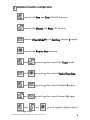
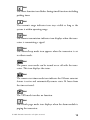
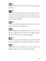
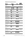
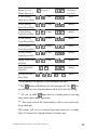
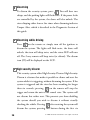
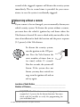
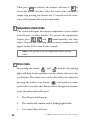
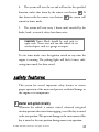
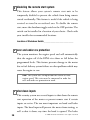
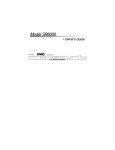
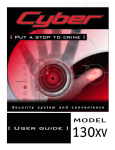
Model 20095
➤Owner’s
Guide
limited lifetime consumer warranty
Directed Electronics (hereinafter "Directed") promises to the original purchaser to repair
or replace with a comparable reconditioned Directed DIY unit if this Directed DIY unit
(hereinafter "Unit"), excluding without limitation, any remote transmitters or associated
accessories, proves defective in materials or workmanship under normal use for the life of
the vehicle which the Unit is originally installed. During this period, so long as the Unit
remained installed in the original vehicle, Directed will at its option, repair or replace this
Unit if it is proved defective in workmanship or material PROVIDED the Unit is
returned to Directed's warranty department at One Viper Way, Vista, CA 92081, along
with $20 postage and handling fee, a bill of sale or other dated proof of purchase bearing
the following information: Date of purchase, name and location of the merchant who sold
the Unit, and product description. This warranty does not cover labor costs for the
removal or reinstallation of the Unit. This warranty is non-transferable and does not apply
to any Unit that has been modified or used in a manner contrary to its intended purpose,
and this warranty does not cover damage to any Unit caused by installation or removal of
the Unit. This warranty is void if the Unit has been damaged by accident or unreasonable
use, neglect, improper service or other causes not arising out of defects in materials or
workmanship. Directed makes no warranty against theft of a vehicle or its contents.
THE FOREGOING WARRANTY IS THE EXCLUSIVE PRODUCT WARRANTY,
OTHERWISE, ALL WARRANTIES INCLUDING BUT NOT LIMITED TO
EXPRESS WARRANTY, IMPLIED WARRANTY, WARRANTY OF MERCHANTABILITY, OR FITNESS FOR A PARTICULAR PURPOSE ARE EXPRESSLY
EXCLUDED AND DISCLAIMED TO THE MAXIMUM EXTENT ALLOWED BY
LAW, AND DIRECTED NEITHER ASSUMES NOR AUTHORIZES ANY PERSON
TO ASSUME FOR IT ANY LIABILITY IN CONNECTION WITH THE SALE OF
THE PRODUCT. DIRECTED HAS ABSOLUTELY NO LIABILITY FOR ANY AND
ALL ACTS OF THIRD PARTIES INCLUDING ITS AUTHORIZED DEALERS OR
INSTALLERS. SOME STATES DO NOT ALLOW THE LIMITATION ON HOW
LONG AN IMPLIED WARRANTY LASTS, SO THE ABOVE LIMITATION MAY
NOT APPLY TO YOU.
LIMITATION OF DAMAGES AND LIABILITY. CONSUMER'S REMEDY IS LIMITED TO REPAIR OR REPLACEMENT OF THE UNIT, AND IN NO EVENT
SHALL DIRECTED'S LIABILITY EXCEED THE PURCHASE PRICE OF THE
UNIT. IN ANY EVENT, DIRECTED SHALL NOT BE LIABLE FOR ANY DAMAGES INCLUDING, BUT NOT LIMITED TO, ANY DIRECT, INDIRECT, INCIDENTAL, SPECIAL, PUNITIVE OR CONSEQUENTIAL DAMAGES, LOST
PROFITS, LOST SAVINGS, OR, TO THE EXTENT ALLOWED BY APPLICABLE
LAW, DAMAGES RESULTING FROM DEATH OR INJURY ARISING OUT OF
© 2005 directed electronics—all rights reser ved
i
OR IN CONNECTION WITH THE INSTALLATION, USE, IMPROPER USE, OR
INABILITY TO USE, THE PRODUCT, EVEN IF THE PARTY HAS BEEN
ADVISED OF THE POSSIBILITY OF SUCH DAMAGES. SOME STATES DO
NOT ALLOW THE EXCLUSION OF LIMITATION OF INCIDENTAL OR CONSEQUENTIAL DAMAGES, SO THE ABOVE LIMITATIONS OR EXCLUSION
MAY NOT APPLY TO YOU. THE CONSUMER AGREES AND CONSENTS THAT
ALL DISPUTES BETWEEN THE CONSUMER AND DIRECTED SHALL BE
RESOLVED IN ACCORDANCE WITH CALIFORNIA LAWS IN SAN DIEGO
COUNTY, CALIFORNIA.
IMPORTANT NOTE:
This product warranty is automatically void if its date code or serial number is defaced,
missing, or altered. This warranty will not be valid unless you have completed the warranty card and mailed it to Directed Electronics. within 10 days after purchase to the
address listed on the warranty registration card.
Make sure you have all of the following information from your dealer:
A clear copy of the sales receipt, showing the following:
Date of purchase
Authorized dealer's company name and address
Item number
ii
© 2005 directed electronics—all rights reser ved
table of contents
limited lifetime consumer warranty . . . . . . . . . . . . . . . . . . . . . . . . . . . . . . . . . . . . . . . . i
remote configurations . . . . . . . . . . . . . . . . . . . . . . . . . . . . . . . . . . . . . . . . . . . . . . . . . 3
LCD 2-way configuration . . . . . . . . . . . . . . . . . . . . . . . . . . . . . . . . . . . . . . . . . . 3
standard 4-button configuration . . . . . . . . . . . . . . . . . . . . . . . . . . . . . . . . . . . . . 5
what is included . . . . . . . . . . . . . . . . . . . . . . . . . . . . . . . . . . . . . . . . . . . . . . . . . . . . . . 6
important information . . . . . . . . . . . . . . . . . . . . . . . . . . . . . . . . . . . . . . . . . . . . . . . . . 6
system maintenance . . . . . . . . . . . . . . . . . . . . . . . . . . . . . . . . . . . . . . . . . . . . . . 7
your warranty . . . . . . . . . . . . . . . . . . . . . . . . . . . . . . . . . . . . . . . . . . . . . . . . . . . 8
fcc/id notice . . . . . . . . . . . . . . . . . . . . . . . . . . . . . . . . . . . . . . . . . . . . . . . . . . . . 8
caution . . . . . . . . . . . . . . . . . . . . . . . . . . . . . . . . . . . . . . . . . . . . . . . . . . . . . . . . 9
remote functions . . . . . . . . . . . . . . . . . . . . . . . . . . . . . . . . . . . . . . . . . . . . . . . . . . . . 10
LCD 2-way remote standard configuration. . . . . . . . . . . . . . . . . . . . . . . . . . . . 10
Standard LCD 2-way icon configuration . . . . . . . . . . . . . . . . . . . . . . . . . . . . . 12
4-button remote standard configuration . . . . . . . . . . . . . . . . . . . . . . . . . . . . . . 18
LCD 2-way remote operation . . . . . . . . . . . . . . . . . . . . . . . . . . . . . . . . . . . . . . . . . . 19
system signal paging features . . . . . . . . . . . . . . . . . . . . . . . . . . . . . . . . . . . . . . . 19
using your system . . . . . . . . . . . . . . . . . . . . . . . . . . . . . . . . . . . . . . . . . . . . . . . . . . . 20
warning! safety first . . . . . . . . . . . . . . . . . . . . . . . . . . . . . . . . . . . . . . . . . . . . . . 20
active arming. . . . . . . . . . . . . . . . . . . . . . . . . . . . . . . . . . . . . . . . . . . . . . . . . . . 22
passive arming. . . . . . . . . . . . . . . . . . . . . . . . . . . . . . . . . . . . . . . . . . . . . . . . . . 23
warn away® response description . . . . . . . . . . . . . . . . . . . . . . . . . . . . . . . . . . . . 24
triggered response description . . . . . . . . . . . . . . . . . . . . . . . . . . . . . . . . . . . . . . 25
multi-level security arming . . . . . . . . . . . . . . . . . . . . . . . . . . . . . . . . . . . . . . . . 26
arming while driving . . . . . . . . . . . . . . . . . . . . . . . . . . . . . . . . . . . . . . . . . . . . . 27
disarming . . . . . . . . . . . . . . . . . . . . . . . . . . . . . . . . . . . . . . . . . . . . . . . . . . . . . 28
disarming while driving. . . . . . . . . . . . . . . . . . . . . . . . . . . . . . . . . . . . . . . . . . . 28
high security disarm . . . . . . . . . . . . . . . . . . . . . . . . . . . . . . . . . . . . . . . . . . . . . 28
disarming without a remote . . . . . . . . . . . . . . . . . . . . . . . . . . . . . . . . . . . . . . . 29
silent mode . . . . . . . . . . . . . . . . . . . . . . . . . . . . . . . . . . . . . . . . . . . . . . . . . . . . 30
panic mode . . . . . . . . . . . . . . . . . . . . . . . . . . . . . . . . . . . . . . . . . . . . . . . . . . . . 30
valet mode. . . . . . . . . . . . . . . . . . . . . . . . . . . . . . . . . . . . . . . . . . . . . . . . . . . . . 31
remote start. . . . . . . . . . . . . . . . . . . . . . . . . . . . . . . . . . . . . . . . . . . . . . . . . . . . 32
valet take-over . . . . . . . . . . . . . . . . . . . . . . . . . . . . . . . . . . . . . . . . . . . . . . . . . . 34
short-run/turbo . . . . . . . . . . . . . . . . . . . . . . . . . . . . . . . . . . . . . . . . . . . . . . . . . 35
setting the clock . . . . . . . . . . . . . . . . . . . . . . . . . . . . . . . . . . . . . . . . . . . . . . . . 35
temperature check mode . . . . . . . . . . . . . . . . . . . . . . . . . . . . . . . . . . . . . . . . . . 36
timer mode . . . . . . . . . . . . . . . . . . . . . . . . . . . . . . . . . . . . . . . . . . . . . . . . . . . . 36
safety features . . . . . . . . . . . . . . . . . . . . . . . . . . . . . . . . . . . . . . . . . . . . . . . . . . . . . . . 37
starter anti-grind circuitry . . . . . . . . . . . . . . . . . . . . . . . . . . . . . . . . . . . . . . . . . 37
disabling the remote start system. . . . . . . . . . . . . . . . . . . . . . . . . . . . . . . . . . . . 38
© 2005 directed electronics—all rights reser ved
1
over and under rev protection . . . . . . . . . . . . . . . . . . . . . . . . . . . . . . . . . . . . . . 38
shut down inputs . . . . . . . . . . . . . . . . . . . . . . . . . . . . . . . . . . . . . . . . . . . . . . . 38
nuisance prevention circuitry . . . . . . . . . . . . . . . . . . . . . . . . . . . . . . . . . . . . . . 39
24-hour timer mode . . . . . . . . . . . . . . . . . . . . . . . . . . . . . . . . . . . . . . . . . . . . . . . . . 40
diagnostics . . . . . . . . . . . . . . . . . . . . . . . . . . . . . . . . . . . . . . . . . . . . . . . . . . . . . . . . . 40
arming diagnostics . . . . . . . . . . . . . . . . . . . . . . . . . . . . . . . . . . . . . . . . . . . . . . 41
disarming diagnostics . . . . . . . . . . . . . . . . . . . . . . . . . . . . . . . . . . . . . . . . . . . . 41
system status chirps . . . . . . . . . . . . . . . . . . . . . . . . . . . . . . . . . . . . . . . . . . . . . . 42
table of zones . . . . . . . . . . . . . . . . . . . . . . . . . . . . . . . . . . . . . . . . . . . . . . . . . . 42
interpreting zone diagnostics . . . . . . . . . . . . . . . . . . . . . . . . . . . . . . . . . . . . . . . 43
code hopping . . . . . . . . . . . . . . . . . . . . . . . . . . . . . . . . . . . . . . . . . . . . . . . . . . . . . . . 44
high frequency . . . . . . . . . . . . . . . . . . . . . . . . . . . . . . . . . . . . . . . . . . . . . . . . . . . . . . 44
owner recognition . . . . . . . . . . . . . . . . . . . . . . . . . . . . . . . . . . . . . . . . . . . . . . . . . . . 45
rapid resume logic . . . . . . . . . . . . . . . . . . . . . . . . . . . . . . . . . . . . . . . . . . . . . . . . . . . 45
power saver mode . . . . . . . . . . . . . . . . . . . . . . . . . . . . . . . . . . . . . . . . . . . . . . . . . . . 46
programming options . . . . . . . . . . . . . . . . . . . . . . . . . . . . . . . . . . . . . . . . . . . . . . . . 46
security & convenience expansions . . . . . . . . . . . . . . . . . . . . . . . . . . . . . . . . . . . . . . 49
glossary of terms . . . . . . . . . . . . . . . . . . . . . . . . . . . . . . . . . . . . . . . . . . . . . . . . . . . . 51
2
© 2005 directed electronics—all rights reser ved
remote configurations
➜ LCD 2-way configuration
4
3
2
5
6
7
8
9
1
31
30
29
28
10
27
11
26
25
12
24
13
23
14
22
15
21
20
16
17
© 2005 directed electronics—all rights reser ved
19
18
3
1
2
3
4
5
6
7
8
9
10
11
12
13
14
15
16
17
18
19
20
21
22
23
24
25
26
27
28
29
30
31
4
Vehicle Interior Temperature Indicator
Numeric Display
AM/PM Indicator
Alarm Clock Mode Indicator
Timer Function Indicator
Transmit Range Indicator
Transmission Indication
Vibrate/Beep Mode Indicator
Power Saver Mode Indicator
Remote Start Timer Mode Indicator
No Function
Vehicle Page Mode Indicator
Full Trigger Shock Sensor Indicator
Hood/Trunk Open or Trigger Indicator
Parking Light Indicator
Door Open or Trigger Indicator
Arm/Lock Button
Disarm/Unlock Button
Remote Start Indicator
Hood/Trunk Open or Trigger Indicator
Remote Start Button
Valet Mode Indicator
Remote Start Safety Shutdown Indicator
Battery Level Indicator
Auxiliary Button
Temperature-Controlled Remote Start Indicator
Silent Arm/Disarm Mode Indicator
Full Trigger Alert Indicator
Arm/Disarm Indicator
Function Button
Celsius/Fahrenheit Indicator
© 2005 directed electronics—all rights reser ved
➜ standard 4-button configuration
controls the Arm and Panic On/Off function.
controls the Disarm and Panic Off function.
controls Silent Mode™ and Auxiliary channel 2 output.
controls the Remote Start function.
and
pressed together control the Timer mode.
and
pressed together control Turbo/Short Run.
and
pressed together control channel 4 output.
and
pressed together control channel 5 output.
and
car temperature.
and
© 2005 directed electronics—all rights reser ved
pressed together display interior
5
what is included
➤
Control module
➤
ASK transceiver/antenna
➤
One 4-button remote
➤
One 2-way LCD remote
➤
Stinger™ DoubleGuard® 2-stage shock sensor
➤
Revenger™ Soft Chirp™ 6-tone programmable siren
➤
Status LED indicator light
➤
Push-button Valet switch
➤
Your warranty registration
➤
Shut-down toggle switch
important information
Congratulations on the purchase of your combination remote
start alarm system. Due to the complexity of this system, it must
be installed by an authorized dealer only. Installation of this
product by anyone other than an authorized dealer voids the
warranty. All dealers are provided with a preprinted dealer certificate to verify authorization.
By carefully reading this Owner's Guide prior to using your
system, you will maximize the use of this system and its features.
You can print additional or replacement copies of this manual by
accessing our web site at www.directed.com.
6
© 2005 directed electronics—all rights reser ved
➜ system maintenance
The system requires no specific maintenance other than battery
replacement for the remotes.
LCD 2-Way Remote Battery Replacement
The 2-way remote is powered by a 1.5V AAA battery. The
Battery Level indicator has three level indicators that serve as a
visual indication of battery charge. When the battery reaches a
low charge level that requires replacement, the transceiver will
generate a single notification chirp, and the Battery Level indicator will flash continuously.
To replace the battery, gently pull the battery cover release tab, then
slide the door down to expose the battery and remove the expired
battery. Place the new battery into the transceiver observing the
correct polarity. When power is returned the transceiver will light
all icons in the LCD and generate all beeper tones once.
4-Button Remote Battery Replacement
Your remote is powered by a small, lightweight 3-volt lithium
battery (CR2032) that will last approximately one year under
normal use. When the battery begins to weaken, operating range
will be reduced and the LED on the remote will dim.
© 2005 directed electronics—all rights reser ved
7
➜ your warranty
Your warranty registration must be completely filled out and
returned within 10 days of purchase. Your product warranty
will not be validated if your warranty registration is not returned.
Make sure you receive the warranty registration from your dealer.
It is also necessary to keep your proof of purchase, which reflects
that the product was installed by an authorized dealer.
➜ fcc/id notice
This device complies with Part 15 of FCC rules. Operation is
subject to the following two conditions: (1) This device may not
cause harmful interference, and (2) This device must accept any
interference received, including interference that may cause
undesirable operation.
Directed Electronics, Inc.
544 Series
Tested to Comply
with FCC Standards
Directed Electronics, Inc.
477T Series
Tested to Comply
with FCC Standards
8
© 2005 directed electronics—all rights reser ved
Directed Electronics, Inc.
474V/P/S Series
Tested to Comply
with FCC Standards
Changes or modifications not expressly approved by the party
responsible for compliance could void the user's authority to
operate this device.
➜ caution
This product is designed for fuel injected, automatic transmission
vehicles only. Use of this product in a standard transmission
vehicle is dangerous and contrary the product's intended use.
© 2005 directed electronics—all rights reser ved
9
remote functions
The remote buttons are used to send commands to the system.
The descriptions below reflect the standard configuration for this
system. The buttons can be custom configured for the user’s
specific needs by the installer.
➜ LCD 2-way remote standard configuration
LCD 2-way button configuration
Button
The System Arm/Lock and Multi-Level Security Arming functions are controlled by pressing this button.
Button
The System Disarm/Unlock and High Security Disarm functions
are controlled by pressing this button.
Button
Channel 2 output is controlled by pressing and holding this
button for two seconds.
Button
The panic feature is controlled by pressing and holding this
button for three seconds. Press again to disable panic mode.
Button
The LCD backlighting will turn on when pressed for less than one
second; when held for more than five seconds the transceiver will
enter adjustment mode allowing the setting of the clock, timer
mode, and audible melody selection. For more information, please
refer to the Function Button Configurations section of this guide.
10
© 2005 directed electronics—all rights reser ved
Button
The remote start function of the system is controlled by pressing
this button twice. To stop the remote start press this button for
one second. Also, stepping on the brake pedal will cancel the
remote start.
Button
When pressed and held this button activates the second unlock
or other accessory.
and
Buttons
When pressed simultaneously these buttons activate remote start
timer mode, engaging the remote start function every 24 hours.
,
and
Buttons
When pressed simultaneously these buttons display the internal
temperature of the vehicle on the LCD.
and
Buttons
When pressed simultaneously with the system armed, the system
enters temperature auto start mode and automatically remote starts
the vehicle if the temperature inside the vehicle drops below
0 degrees Fahrenheit.
note: Disarming the system while in temperature auto start
mode will cause the system to exit this mode.
and
Buttons
The numeric display toggles between the time of the day and the
alarm clock when these buttons are pressed simultaneously.
© 2005 directed electronics—all rights reser ved
11
and
Buttons
Press these buttons simultaneously to activate the parking timer.
Each additional press will toggle through the available options
(10 min., 20 min., 30 min., 1 hour, 1.5 hours, 2 hours, and off ).
and
Buttons
When pressed simultaneously these buttons toggle between beep
notification and vibrate notification.
and
Buttons
When pressed simultaneously these buttons activate battery
saver mode, which will drop power consumption on the transceiver battery to zero when the alarm is inactive or disarmed.
➜ Standard LCD 2-way icon configuration
Icon
The vehicle interior temperature icon displays the temperature
of the inside of the vehicle when prompted.
Icon
The numeric display icon will show the hours and minutes.
Icon
The AM/PM icon indicates the time before or after noon.
Icon
The alarm clock mode icon indicates that the alarm clock mode
is active.
12
© 2005 directed electronics—all rights reser ved
Icon
The timer function icon flashes during timed functions including
parking timer.
Icon
The transmit range indicator icon stays visible as long as the
system is within operating range.
Icon
The remote transmission indicator icon displays when the transceiver is transmitting a signal.
Icon
The vibrate/beep mode icon appears when the transceiver is set
to vibrate mode.
Icon
The power saver mode can be turned on or off with the transceiver. This icon displays the status.
Icon
The remote start timer mode icon indicates the 24-hour autostart
feature is active and automatically remote starts 24 hours from
the time activated.
Icon
The VRS mode icon has no function.
Icon
The vehicle page mode icon displays when the alarm module is
paging the transceiver.
© 2005 directed electronics—all rights reser ved
13
Icon
The full trigger shock sensor icon indicates that the shock sensor
has been triggered by a hard shock.
and
Icons
The hood/trunk open or trigger icon illuminates when the hood
or trunk trigger has been activated or the hood or trunk is open,
and bypasses those zones until it is closed.
Icon
The parking light icon will flash twice when armed or disarmed.
The icon also flashes during WarnAway and at the beginning and
end of remote start cycles.
Icon
The door open or trigger icon illuminates when the door trigger
has been activated or the door is open, and bypasses that zone
until it is closed.
Icon
The remote start icon indicates when the vehicle is remotely
started.
Icon
The Valet mode icon appears when the system is in Valet mode.
Icon
The remote start safety shut down icon indicates the vehicle may be
in gear or other unsafe condition inhibiting remote start operation.
14
© 2005 directed electronics—all rights reser ved
Icon
The battery level icon indicates the level of power remaining in
the battery.
Icon
The temperature-controlled remote start icon indicates that the
system has entered the temperature remote start mode and automatically starts the vehicle if the temperature of the vehicle drops
below 0 degrees Fahrenheit.
Icon
The silent arm/disarm icon appears when the system has been
armed or disarmed in the silent mode.
Icon
The full trigger alert icon illuminates when the security system
has been triggered by a heavy impact, door trigger violation,
optional sensor violation, or a hood/trunk trigger.
Icon
The arm icon appears when the vehicle is armed and locked. The
disarm icon appears when the vehicle is disarmed and unlocked.
Icon
Celsius/Fahrenheit icon indicates the current mode of the
displayed temperature either in Celsius or Fahrenheit.
© 2005 directed electronics—all rights reser ved
15
Standard LCD 2-way button functions
Function
Button
Icon
Audible
Indication
Lamp On
(10 sec)
16
Power-Saver Mode*
+
Melody
Beep/Vibrate Mode
+
4 Vibrations/
1 Beep
Time Adjust
Mode (hour)**
for 5 Seconds
Time Adjust
Mode (min)**
1 Time***
Alarm Clock
Set Mode (hour)**
2 Times***
Alarm Clock
Set Mode (min)**
3 Times***
Alarm Clock Music
or Power on Music
Selection**
4 Times***
Alarm Clock Adjust
Mode (on/off )**
5 Times***
Timer Count Down
Adjust Mode
(hour)**
6 Times***
Timer Count Down
Adjust Mode
(min)**
7 Times***
Timer Count
Down Ending Melody
Selection 1**
8 Times***
RS Timer Count
Down Mode (on/off )*
9 Times***
2 Beeps
5 Selections
1/2/3/4/5
5 Selections
1/2/3/4/5
© 2005 directed electronics—all rights reser ved
Remote Start On
Melody Selection 2
10 times***
5 Selections
1/2/3/4/5
10 Min Parking
Count Down Mode
+
1 Time
Melody
20 Min Parking
Count Down Mode
+
2 Times
Melody
30 Min Parking
Count Down Mode
+
3 Times
Melody
60 Min Parking
Count Down Mode
+
4 Times
Melody
90 Min Parking
Count Down Mode
+
5 Times
Melody
120 Min Parking
Count Down Mode
+
6 Times
Melody
Parking Count Down
Off Mode
+
7 Times
Melody
+
Alarm Clock Mode
On/Off****
Celsius/Fahrenheit
Select Mode
+
Melody
+
or
Melody
* This function will operate in the disarmed state only.
** The
button will advance the selection upward. The
button will advance the selection downward or select the off setting.
*** Be sure to hold
down for five seconds prior to entering
timer clock adjust mode operation.
**** Press once to have the alarm clock on. Press twice to have the
alarm clock off.
The remote will revert to normal operation from the set mode
when 15-seconds has elapsed without a button entry.
© 2005 directed electronics—all rights reser ved
17
➜ 4-button remote standard configuration
Button
The arming is controlled by pressing this button. The panic
alarm is triggered by pressing and holding this button. Press this
button again to cancel the panic alarm.
Button
The disarming function is controlled by pressing this button.
Button
Silent Mode™ and an optional auxiliary function are controlled
by this button. (Silent Mode works by pressing this button for
less than one second before arming or disarming. An optional
auxiliary function, such as trunk release, can be controlled by
pressing and holding this button for 1.5 seconds.)
The auxiliary output controls __________________________.
Button
The remote start function of your system is controlled by
pressing this button.
and
Buttons
An optional auxiliary convenience or expansion function that
you have added to your system can be activated by pressing these
buttons simultaneously.
The auxiliary output controls __________________________.
18
© 2005 directed electronics—all rights reser ved
and
Buttons
An optional auxiliary convenience or expansion function that
you have added to your system can be activated by pressing these
buttons simultaneously.
The auxiliary output controls __________________________.
and
Buttons
The remote start timer mode is controlled by pressing these
buttons simultaneously.
and
Buttons
The short-run turbo mode is activated when these buttons are
pressed simultaneously.
LCD 2-way remote operation
The remote start system operates at 434 MHz and incorporates
Directed’s proprietary A.S.K. out-board two-way transceiver. The
high frequency combined with Binary Data communication
achieves superior range with two-way communication.
➜ system signal paging features
A page is the signal the control module sends to the transceiver as
confirmation of receipt of a command or alarm system status.
When the transceiver receives a page it will generate a page notification to the user (notifications are audible beeps or the remote
vibrates) and the LCD icons will display the current system status.
© 2005 directed electronics—all rights reser ved
19
Command Page
When a command (arm/disarm, remote start, or auxiliary
channel) from the transceiver is sent and received, the system will
send a command page back to confirm receipt.
Page Recognition Mode
The transceiver will leave a zone icon illuminated when it has
received a triggered response and will wait for violation recognition. Press any button on the transceiver, the LCD information
and alarm page alerts will be cleared.
note: The transceiver buttons will not send a command
to the system until the alarm page is cleared.
using your system
➜ warning! safety first
The following safety warnings must be observed at all times:
➤
Due to the complexity of this system, installation of this
product must only be performed by an authorized Directed
dealer.
➤
When properly installed, this system can start the vehicle via
a command signal from the remote control. Therefore, never
operate the system in an enclosed area or partially enclosed
area without ventilation (such as a garage). When parking in
an enclosed or partially enclosed area or when having the
20
© 2005 directed electronics—all rights reser ved
vehicle serviced, the remote start system must be disabled
using the installed toggle switch. It is the user's sole responsibility to properly handle and keep out of reach from children all remote controls to assure that the system does not
unintentionally remote start the vehicle. THE USER MUST
INSTALL A CARBON MONOXIDE DETECTOR IN
OR ABOUT THE LIVING AREA ADJACENT TO THE
VEHICLE. ALL DOORS LEADING FROM ADJACENT
LIVING AREAS TO THE ENCLOSED OR PARTIALLY
ENCLOSED VEHICLE STORAGE AREA MUST AT
ALL TIMES REMAIN CLOSED. These precautions are the
sole responsibility of the user.
➤
Use of this product in a manner contrary to its intended
mode of operation may result in property damage, personal
injury, or death. (1) Never remotely start the vehicle with the
vehicle in gear, and (2) Never remotely start the vehicle with
the keys in the ignition. The user must also have the neutral
safety feature of the vehicle periodically checked, wherein the
vehicle must not remotely start while the car is in gear. This
testing should be performed by an authorized Directed dealer
in accordance with the Safety Check outlined in the product
installation guide. If the vehicle starts in gear, cease remote
start operation immediately and consult with the authorized
Directed dealer to fix the problem.
➤
After the remote start module has been installed, contact
your authorized dealer to have him or her test the remote
start module by performing the Safety Check outlined in the
© 2005 directed electronics—all rights reser ved
21
product installation guide. If the vehicle starts when
performing the Neutral Safety Shutdown Circuit test, the
remote start unit has not been properly installed. The remote
start module must be removed or the installer must properly
reinstall the remote start system so that the vehicle does not
start in gear. All installations must be performed by an authorized Directed dealer. OPERATION OF THE REMOTE
START MODULE IF THE VEHICLE STARTS IN GEAR
IS CONTRARY TO ITS INTENDED MODE OF OPER ATION. OPERATING THE REMOTE START SYSTEM
UNDER THESE CONDITIONS MAY RESULT IN
PROPERTY DAMAGE OR PERSONAL INJURY. YOU
MUST IMMEDIATELY CEASE THE USE OF THE
UNIT AND SEEK THE ASSISTANCE OF AN AUTHO RIZED DIRECTED D E A L E R T O R E P A I R O R
DISCONNECT THE INSTALLED REMOTE START
MODULE. DIRECTED WILL NOT BE HELD
RESPONSIBLE OR PAY FOR INSTALLATION OR
REINSTALLATION COSTS.
➜ active arming
You can arm the system by pressing
of your remote for one
second. When the system arms, you will hear a short siren sound,
or chirp, and see the parking lights flash once. If the power door
locks are controlled by the system, the doors will also lock. While
the system is armed, the status LED will flash approximately once
per second, indicating that the system is actively protecting your
vehicle. If you hear a second chirp after arming and note that the
22
© 2005 directed electronics—all rights reser ved
status LED is flashing in groups, see the Diagnostics Section of
this guide. This extra chirp is called Bypass Notification, which
indicates that a security sensor or switch has been bypassed and
the system is not monitoring that area (zone) of the vehicle.
➜ passive arming
The system can be programmed to arm itself automatically (called
passive arming). If the system is programmed for passive arming, it
will automatically arm 30 seconds after the ignition is turned off
and the system detects that you have left the vehicle by opening and
closing a door. Whenever the system is in its 30-second passive
arming countdown, the status LED will flash twice as fast as it does
when the system is armed. At the 20-second point of the countdown, the siren will chirp to indicate that the system is about to
arm. At the 30-second point, the parking lights will flash to indicate
that the system is armed.
note: If any protected entry point (such as a door or a
switch-protected trunk or hood) is open, the system will
not passively arm (unless forced passive arming is programmed on. See Programming Options section.) Additionally, each time a sensor is triggered during the arming
countdown, the 30-second countdown starts over.
When armed your vehicle is protected as follows:
➤
➤
Light impacts trigger the Warn Away® signal. When triggered,
the siren chirps and the parking lights flash for a few seconds.
Heavy impacts trip a Triggered Sequence. The sequence
consists of the siren sounding continuously and the parking
lights flashing for a pre-programmed period, which can range
in duration from 1 to 180 seconds.
© 2005 directed electronics—all rights reser ved
23
➤
➤
➤
If a door is opened, the system will immediately start
chirping the siren and flashing the parking lights. Three
seconds later, the siren output changes to a continuous blast.
This progressive response gives you time to disarm the system
with your remote if you inadvertently open the door while
the system is armed, while still providing instant response
(even if the door is immediately closed).
Turning on the ignition key will trip the same progressive response as opening a door.
The optional starter kill prevents the vehicle’s starter from
cranking.
➜ warn away® response description
A Warn Away® Response consists of an alarm page along with the
responses described below.
➤
➤
➤
➤
Shock Sensor - Light impacts to the vehicle will flash the
vehicle lights and chirp the siren for a few seconds.
Remote Control Notification - Ten quick beeps (or one
vibration).
Remote Control LCD - The full trigger alert icon (28) will
dimly illuminate for two seconds
The transceiver will enter Page Recognition Mode and
operate alarm page alerts.
note: Icons 13 and 14 represent alarm system zone
inputs. For more information about icons and the zones
they represent refer to the Standard Remote
Configurations section.
24
© 2005 directed electronics—all rights reser ved
➜ triggered response description
A Triggered Response can be activated by any of the triggers listed
below and consists of an alarm page along with the response
described for each trigger. The default Triggered Response duration is 30 seconds but can be programmed from 1-180 seconds
by your installer with the Directed Bitwriter®.
➤
Sensor Trigger - Heavy impacts to the vehicle will instantly
sound the siren and flash the lights for the programmed
duration and report Zone 2.
➤
Door Trigger - If a door is opened the siren will chirp for three
seconds, then the siren will sound and the lights will flash for
the programmed duration and report Zone 3. The three
seconds allow the user time to disarm the system with a
minimum of noise should a door be opened inadvertently
➤
➤
➤
while the system is armed.
Hood Trigger - Opening the hood will sound the siren, flash
the lights for the programmed duration, and report Zone 1.
Trunk Trigger - Opening the trunk (if connected) will
instantly sound the siren and flash the lights for the
programmed duration and report Zone 4.
Ignition Trigger - If the ignition is turned on the siren will
chirp for three seconds, then the siren will sound and the lights
will flash for the programmed duration and report Zone 5.
When a Triggered Response is activated the transceiver will:
➤
➤
Repeat four quick beeps (or vibrate) for 15 seconds.
The full trigger alert icon (28) will turn on for 15 seconds.
© 2005 directed electronics—all rights reser ved
25
➤
➤
The zone icons will turn on and remain on until a transceiver
button is pressed, clearing the page alert.
The transceiver will enter page recognition mode and
generate alarm page alerts.
note: Icons 13, 14, 16, and 20 represent alarm system
triggered sequence zone inputs. For more information
about icons and the zones they represent refer to the
Standard Remote Configurations section.
➜ multi-level security arming
Multi-Level Security Arming allows you to select which of the
system's inputs or sensors will be active and which will be
bypassed when the system is armed. (See Table of Zones section
of this guide.) Pressing
(only in Standard Configuration)
again within five seconds of arming the system will activate the
Multi-Level Security feature. Each time
is pressed again, a
different security level is selected. The different security levels are
selected as follows:
➤
Press
once: The siren chirps once. The system is armed.
➤
Press
a second time within five seconds: The siren chirps
twice followed by a long chirp. Zone 2 is now bypassed.
➤
Press
a third time within five seconds: The siren chirps
three times followed by a long chirp. Zone 4 is now bypassed.
➤
Press
a fourth time within five seconds: The siren chirps
four times followed by a long chirp. Zones 2 and 4 are now
bypassed.
26
© 2005 directed electronics—all rights reser ved
➤
Press
a fifth time within five seconds: The siren chirps
five times followed by a long chirp. All input zones, except
the ignition, are now bypassed.
note: Multi-Level Security Arming only applies to a single arming cycle. Once the system is disarmed and then
re-armed, all the zones will be active again.
➜ arming while driving
Your security system can be armed while driving the vehicle!
Simply press
on the remote for two seconds while the
vehicle is running. The siren will chirp once to indicate that the
security system is armed, and then once more to indicate that the
ignition is on. The system will not respond to any input except
the door triggers, and the starter kill relay (if installed) will not
be activated. Once you have arrived at your destination, the
system will disarm when the ignition is turned off. The siren will
chirp twice and the LED will then stop flashing. The system can
also be disarmed at any time by pressing
.
The LCD 2-way remote will beep once (or vibrate), and the arm
icon (29) will be displayed on the LCD.
note: If the transceiver received a Warn Away® or triggered
response page while armed, the first press of the unlock
button will clear the page alert. A second press will turn
the siren off, and a third press will disarm the system.
© 2005 directed electronics—all rights reser ved
27
➜ disarming
To disarm the security system, press
. You will hear two
chirps, and the parking lights will flash twice. If the power locks
are controlled by the system, the doors will also unlock. The
siren chirping either four or five times when disarming indicates
Tamper Alert, which is described in the Diagnostics Section of
this guide.
➜ disarming while driving
Press
on the remote or simply turn off the ignition to
disarm the system. The lights will flash twice, the doors will
unlock, the siren will chirp twice, and the status LED will turn
off. The 2-way remote will beep twice (or vibrate). The disarm
icon (29) will be displayed on the LCD.
➜ high security disarm
This security system offers High Security Disarm. High Security
Disarm is a feature that makes it possible to silence and reset the
system while it is triggering, without disarming the system. If the
system is triggered and the siren has been sounding for longer
than six seconds, pressing
on the remote will stop the
trigger and return the unit to the armed state. The system will
not disarm, but rather reset. This prevents you from disabling
the system should you wish to disarm it without visually
checking the vehicle. Pressing
after resetting the system will
disarm the system; pressing this button during the first six
28
© 2005 directed electronics—all rights reser ved
seconds of the triggered sequence will disarm the security system
immediately. The six second timer is provided for your convenience, in case the system is accidentally triggered.
➜ disarming without a remote
If your remote is lost or damaged, you can manually disarm your
vehicle security system. To disarm the system without a remote,
you must have the vehicle's ignition key and know where the
Valet button is located. Be sure to check with your installer at the
time of installation for both the location and the preset response
(1-5 presses) of the Valet button.
To disarm the security system,
turn the ignition to the ON position. Press the Valet button the
preset number of times (one to
DRW-35
five times) within 15 seconds.
After five seconds, the system will
disarm. If the system does not
disarm, you may have waited too
long; turn the ignition off and on
and try again.
Location of Valet Button_________________________________
Number of Presses_____________________________________
important! The Valet button can be programmed to
respond to 1-5 presses for the disarm function. You must
check with the installer to verify the programming for
your individual unit.
© 2005 directed electronics—all rights reser ved
29
➜ silent mode
To temporarily turn off the arm or disarm chirps, use Silent
Mode™. Simply press
for less than one second before
arming or disarming, and the confirmation chirp(s) will be eliminated for that one operation only. If you want the arm/disarm
chirps turned off permanently, your dealer can do this for you.
note: The Warn Away® response to lighter impacts is
bypassed if the system is armed using Silent Mode. This
ensures that no chirps will be emitted by the siren in an
area you want chirp-free. The system is still fully capable
of triggering. Only the Warn Away® response is bypassed.
➜ panic mode
If you are threatened in or near your vehicle, you can attract
attention by triggering the system with your remote. Just press
for two seconds, and you will enter Panic Mode. The siren
will sound and the parking lights will flash for the programmed
siren duration. To stop Panic Mode at any time, press
on
the remote again.
note: Once panic mode has been entered, the siren will
sound for the programmed duration.
The LCD 2-way remote will beep (or vibrate) continuously
when the system enters panic mode. The 2-way remote will not
generate a page notification when panic mode is exited.
30
© 2005 directed electronics—all rights reser ved
➜ Valet mode
You can prevent your security system from automatically arming
and triggering by using Valet Mode. This is very useful when
washing the vehicle or having it serviced. In Valet Mode, the
security system will not arm, even with the remote, but all
convenience functions (door locks, trunk release, etc.) will
continue to work normally.
To enter or exit Valet Mode:
1. Turn the ignition on.
2. Turn the ignition off.
DRW-35
3. Press and release the Valet
button within 10 seconds.
The status LED will light solidly if you are entering Valet Mode,
and it will go out if you are exiting Valet Mode.
To enter or exit Valet Mode using the remote:
Steps 2 through 3 must be quickly and smoothly completed.
1. Open any vehicle door.
2. Press
.
3. Press
.
4. Press
again.
The status LED will light solidly if you are entering Valet Mode,
and it will go out if you are exiting Valet Mode.
© 2005 directed electronics—all rights reser ved
31
➜ remote start
This feature allows you to remotely start and run your vehicle for
a programmable period of time. This makes it possible to warm
up the engine, as well as adjust the interior temperature of the
vehicle with the climate control system. If interior heating or
cooling is desired, the climate controls must be preset, and the
fan blower must be set to the desired level prior to remote
starting the vehicle.
important! (1) Never remote start your vehicle when the
keys are in the ignition, except when performing Valet
Take-Over, and (2) Never start the vehicle if it is not in
either PARK or NEUTRAL.
To remote start the vehicle:
1. Press
on the remote twice within 3 seconds.
2. The parking lights will flash to confirm that the vehicle will
attempt to start.
3. A remote start page notification with a unique melody (or
vibration) will be generated and the LCD will display the
remote start (19) icon as long as the vehicle is running.
note: The 2-way remote will generate a Page Notification
with a different unique two-tone beep (or vibrate) and
the remote start (19) icon will turn off when the remote
start shuts down.
4. In gasoline vehicles, the engine will start 4 seconds after the
parking lights flash. In diesel vehicles, the engine will start
when the WAIT-TO-START indicator on the vehicle's dash
goes out.
32
© 2005 directed electronics—all rights reser ved
5. Once the vehicle has started, it will run for the pre-programmed period of time (either 12, 24, or 60 minutes - see
Programming Options section of this guide) or until a shutdown input is triggered.
important! It is unsafe to operate a vehicle’s motor in a
garage or other closed off area. Breathing the exhaust
from the vehicle is hazardous to your health. Never activate the remote start in an enclosed space.
When you are ready to drive the vehicle:
1. Insert the ignition key and turn
it to the ON (not START) position.
2. Press the brake pedal.
note: If the brake pedal is pressed before the key is in the
ON position, the engine will shut down.
While the vehicle is running during remote start operation, the
system will monitor the vehicle and will automatically shut
down the engine if the system receives any of the following shutdown inputs:
➤
The brake pedal is pressed.
➤
The hood is opened.
➤
The shutdown toggle switch is put into the OFF position.
➤
The pre-programmed run time (12, 24, or 60 minutes) has
elapsed.
➤
Remote button
is pressed twice within 3 seconds.
The LCD 2-way remote will generate a page notification with a
© 2005 directed electronics—all rights reser ved
33
unique melody (or vibrate) and the remote start icon (19) will
turn off when the remote start shuts down.
➜ valet take-over
The Valet Take-Over feature allows the vehicle to remain
running after the key has been removed from the ignition. This
feature is useful for occasions when you wish to exit and lock the
vehicle for short periods of time, but would like to leave the
motor running and the climate controls on.
To perform Valet Take-Over:
1. Before turning off the engine, press and release
twice
within 3-seconds on the remote (or press and release the
optional momentary switch). Then wait five seconds. A
remote start page notification with a unique melody (or
vibration) will be generated and the LCD 2-way remote will
display the remote start icon (19) as long as the vehicle is
running. Then wait three seconds.
2. Turn the ignition key to the OFF position. (The engine will
stay running.)
3. The engine will run until the pre-programmed time elapses
or a shut-down input is received. (See the previous Remote
Start section for a complete list of shut-down inputs.)
note: This feature will not work if the brake pedal is
being pressed.
34
© 2005 directed electronics—all rights reser ved
➜ short-run/turbo
Short run turbo mode keeps the engine running after arriving at
you destination for a programmable period of 1, 3, 5 or 10
minutes. This allows the system’s timer to conveniently cool
down the turbo after you have left the vehicle.
To activate:
1.
Park the vehicle and set parking brake.
2.
Remove your foot from the brake pedal and leave the
engine running.
3.
Press and release the
and
buttons at the same
time.
4.
The lights will flash to indicate the remote start has entered
short run turbo mode.
5.
Turn off the key, the engine will keep running.
6.
Exit and secure the vehicle.
7.
The engine will turn off after the programmed run time.
➜ setting the clock
To set the clock press and hold
for five seconds, the trans-
ceiver will chirp twice and the hour selection will start flashing.
Immediately press
to advance the hour selection or
to
reverse the hour selection. Once the correct hour is displayed
press
again and the minute selection will start flashing.
© 2005 directed electronics—all rights reser ved
35
Then press
to advance the minute selection or
to
reverse the minute selection. Once the correct time is displayed
simply stop pressing any buttons for 15 seconds and the transceiver will automatically exit the clock mode.
➜ temperature check mode
This system will report the interior temperature of your vehicle
with the press of three buttons. To activate the temperature
display press
,
and
simultaneously and then
release. You will hear a melody and the interior temperature will
appear on the LCD screen for five seconds.
note: If the ignition is on, the temperature check will not
work.
➜ timer mode
By pressing the remote
and
buttons the parking
lights will flash 4 times and then start the vehicle and run for the
set duration. The remote start can be shut off by the remote by
pressing the remote start button
and remain in timer
mode, but if any other shut down zones or the ignition becomes
active the timer mode will cancel.
36
1.
Press Timer mode buttons.
2.
The vehicle will confirm with 4 parking light flashes.
3.
A 1-second delay will start.
© 2005 directed electronics—all rights reser ved
4.
The system will start the car and will run for the specified
duration, unless shut down by the remote start button
shut down with the remote start button
. If
the system will
remain in timer mode.
5.
The system will start every 3 hours until canceled by the
brake, hood, or neutral safety shut-down wires.
important!! Timer Mode should be used only in
open areas. Never start and run the vehicle in an
enclosed space such as a garage or carport.
To exit timer mode, turn the ignition switch on any time the
engine is running. The parking lights will flash 4 times, indicating timer mode has been exited.
safety features
This system has several important safety features to ensure
proper operation of the motor and prevent accidental damage to
the engine or its components.
➜ starter anti-grind circuitry
Whenever the vehicle is remote started, advanced anti-grind
circuitry prevents the starter from engaging, even if the key is turned
to the start position. This prevents damage to the starter motor if the
key is turned to the start position during remote start operation.
© 2005 directed electronics—all rights reser ved
37
➜ disabling the remote start system
This feature allows your system's remote start unit to be
temporarily disabled to prevent the vehicle from being remote
started accidentally. This feature is useful if the vehicle is being
serviced or stored in an enclosed area. To disable the remote
start, move the shutdown toggle switch to the OFF position. The
switch can be installed in a location of your choice. Check with
your installer for recommended locations.
Location of Shutdown Switch____________________________
➜ over and under rev protection
The system monitors the engine speed and will automatically
shut the engine off if the RPMs rise above or fall below the
programmed levels. This feature prevents damage to the motor
due to fuel delivery system failures or other problems which may
cause the engine to race.
note: The system uses an input from the vehicle to sense
engine speed. This wire must be connected in order for
over and under rev protection to work.
➜ shut down inputs
This security system uses several inputs to shut down the remote
start operation of the motor or prevent remote start if certain
inputs are active. The two most important are hood and brake
inputs. The hood input will prevent the motor from starting, as
well as shut it down, any time the hood is opened. The brake
38
© 2005 directed electronics—all rights reser ved
pedal will shut down the motor at any time during remote start
operation, as well as preventing the remote start from activating
while it is being pressed.
➜ nuisance prevention circuitry
Your system has Directed’s Nuisance Prevention® Circuitry
(NPC). It prevents annoying repetitive trigger sequences due to
faulty door pin switches or environmental conditions such as
thunder, jackhammers, airport noise, etc.
Example
If the alarm triggers three times within a 60-minute period and
each time the same sensor or switch triggers the alarm, NPC will
interpret those triggers as false alarms. After the third trigger,
NPC ignores, or bypasses, that sensor or switch (along with any
other sensors or switches sharing the same zone) for 60 minutes.
If the bypassed sensor tries to trigger the security system while it
is being bypassed, the 60-minute bypass period will start over.
This ensures that a sensor that is continually being triggered will
remain bypassed.
The vehicle doors are protected by NPC differently. If your security system is triggered by an open door for three full cycles, the
system will bypass the doors until the trigger ceases.
© 2005 directed electronics—all rights reser ved
39
note: Arming and disarming the system does not reset
this function! The only ways to reset a bypassed zone are
for it to not trigger for 60 minutes, or to turn on the ignition. If testing your system, it is important to remember
that the NPC programming can cause zones to be
bypassed and appear to stop working. If five chirps are
heard when disarming, NPC has been engaged. If you
wish to clear the NPC memory, turn the ignition on.
24-hour timer mode
To enter timer mode, press
and
simultaneously. The 2-
way remote will produce a melody and the clock indicator will
appear on the remote’s LCD. Once in Timer Mode, the system
will remote start every 24 hours. Repeat this procedure to turn
Timer Mode off.
diagnostics
The microprocessor at the heart of your system is constantly
monitoring all of the switches and sensors connected to it. It is
designed to detect any faulty switches and sensors and prevents
them from disabling the entire system. The microprocessor will
also record and report any triggers that occurred during your
absence. Refer to the System Status Chirps and Table of Zones
sections of this guide for diagnostic information.
40
© 2005 directed electronics—all rights reser ved
➜ arming diagnostics
If the security system is armed at the same time that an input is
active (such as a door opening or sensor triggering), you will hear
one siren chirp to indicate arming and a second siren chirp to indicate Bypass Notification. A Bypass Notification chirp means that
the security system ignores the input that was active when the
system was armed, until that input ceases. Three seconds after that
input ceases, the security system will resume normal monitoring.
For example, if your vehicle has an interior light exit delay and you
arm your security system before the interior light turns off, you
may hear a second Bypass Notification chirp. Once the light turns
off, however, the security system resumes normal monitoring.
note: Bypass Notification does not occur when the system is in Silent Mode or if the notification chirps have
been programmed off by the installer.
➜ disarming diagnostics
Extra chirps that are heard when disarming the system are the
Tamper Alert. If four chirps are heard when disarming the
system, then the security system was triggered in your absence. If
five chirps are heard when disarming the system, a zone was triggered so many times that the Nuisance Protection® Circuitry has
bypassed that zone. In either case, the status LED will indicate
which zone was involved (see Table of Zones section). The security system will retain this information in its memory and chirp
four or five times each time it is disarmed, until the next time
that the ignition is turned on.
© 2005 directed electronics—all rights reser ved
41
➜ system status chirps
The siren will chirp when arming/disarming the system. The
pattern of chirps will audibly report the system’s status as
described below.
Action
Number of Chirps
Description
Arm
1
System armed
Arm
1 (3-second delay), 1
System armed with
Bypass Notification
Disarm
2
System disarmed
Disarm
4
System disarmed with
Tamper Alert
Disarm
5
System disarmed NPC
active
➜ table of zones
A zone is represented by the number of LED flashes used by the
system to identify a particular type of input. Standard input
assignments are listed in the following table, along with spaces to
write in any optional sensors or switches that have been installed.
42
© 2005 directed electronics—all rights reser ved
ZONE
(Number of
LED Flashes)
DESCRIPTION
1
Trunk Pin
2
Instant trigger - a heavier impact
detected by the shock sensor
3
Door switch trigger
4
Instant trigger - for optional
sensors
5
Ignition trigger
6
Hood Pin
DEALER-INSTALLED
OPTIONS
➜ interpreting zone diagnostics
Warn Away responses are not reported by arming or disarming
diagnostics. If you receive a Bypass notification when arming or
a Tamper Alert notification when disarming, look at the LED.
Active or triggered zones will be indicated by a pattern of blinks
by the LED.
Example
If zone 3 was active or triggered, the LED will blink three times
with a two-second pause. Then it will blink three times again,
and repeat until the ignition is turned on.
note: Your system stores the last two triggered zones in
memory. If your system has been triggered but the LED
has been reset by turning on the ignition, your dealer can
still recall the last two zones that were triggered. Contact
your dealer for details.
© 2005 directed electronics—all rights reser ved
43
code hopping
The receiver and remotes use a mathematical formula called an
algorithm to change their code each time the remote is used.
This technology has been developed to increase the security of
the unit. The control unit knows what the next codes should be.
This helps to keep the remote “in sync” with the control unit
even if you use the remote control out of range of the vehicle.
However, if the remote has been pressed many times out of range
of the vehicle, or the battery has been removed, it may fall out of
sync with the control unit and fail to operate the system. To resync the remote simply press
several times within range of
the vehicle. The alarm will automatically re-sync and respond to
the remote normally.
high frequency
Your system transmits and receives at 434 MHz. This provides a
cleaner spectrum with less interference and a more stable signal.
Enjoy a phenomenal increase in range, even in areas with high radio
interference.
44
© 2005 directed electronics—all rights reser ved
owner recognition
Owner Recognition is a revolutionary new feature available only
from Directed. Using a Directed Bitwriter, hand-held programming tool, your dealer can program many of the system settings.
The programmer makes it possible to program different settings
for each remote that is used with the system. Then, whenever a
specific remote is used, the system will recall the settings assigned
to that remote. Owner Recognition lets up to four users of the
system have different settings that meet their specific needs. It is
almost like having four separate alarms in your vehicle, one for
each user.
note: Owner Recognition cannot be programmed without a Bitwriter and the necessary software. Check with
your dealer for more information.
rapid resume logic
This Directed system will store its current state to non-volatile
memory. If power is lost and then reconnected the system will
recall the stored state from memory. This means if the unit is in
Valet Mode and the battery is disconnected for any reason, such
as servicing the car, when the battery is reconnected the unit will
still be in Valet Mode. This applies to all states of the system
including arm, disarm, and Valet Mode.
© 2005 directed electronics—all rights reser ved
45
power saver mode
Your system will automatically enter Power Saver Mode while
armed or in Valet Mode, after a period of time in which no operation has been performed. This lowers the current draw on the
vehicle's battery. Power Saver Mode takes over under the
following conditions:
➤
Power Saver when the system is armed: After the system has
been armed for 24 hours the LED will flash at half its normal
rate, decreasing the system's current draw.
➤
Power Saver in Valet Mode: When the system enters Valet
Mode the LED illuminates steadily. If the vehicle is not used
(ignition is not turned on) for a one hour period while the
system is in Valet Mode, the LED will shut off. If the system
remains in Valet Mode, the LED will come back on the next
time the ignition is turned on and then back off.
programming options
Programming options control your system's normal, operational
set-up. Most options do not require additional parts, but some
may require installation labor.
The following is a list of the programmable options, with the
factory settings in Bold.
➤
Active arming (from remote only) or passive arming (automatic arming 30 seconds after the last door has been closed).
➤
46
Arming/disarming siren chirps on or off.
© 2005 directed electronics—all rights reser ved
➤
The ignition controlled door lock feature on or off: When this
feature is programmed on, the doors will lock three seconds
after the ignition is turned on, and unlock when the ignition
is turned off. If your installer is programming the security
system with the Directed Bitwriter, ignition lock and unlock
are independent features that can be programmed separately.
➤
Passive door locking (with passive arming) or active door
locking (only when arming with the remote). Passive locking
allows the vehicle's doors to lock when the security system
passively arms (after the 30-second countdown). This
feature only works if passive arming has been programmed.
➤
Panic mode enabled/disabled when the ignition is turned on.
(Some states have laws against sirens sounding in moving
cars.)
➤
Forced passive arming on or off. If your security system is
programmed for passive arming and the forced passive
arming feature has been programmed on, the system will
passively arm after one hour, even if a protected entry has
been left open. Forced passive arming ensures that the
system will be armed if a door has accidentally been left ajar
when leaving the vehicle.
note: When the system passively arms after one hour, the
entry point that has been left open, and anything connected to the same zone, is bypassed and cannot trigger
the system. However, the remaining inputs to the system
are fully operational.
© 2005 directed electronics—all rights reser ved
47
➤
Full trigger response 30 or 60 seconds: This determines how
long the full triggered sequence lasts. Some states have laws
regulating how long a security system can sound before it is
considered a nuisance. If your installer is programming the
security system with the Directed Bitwriter, the full triggered
response can be programmed for any duration ranging from
➤
1 to 180 seconds.
Automatic Engine Disable (AED) on or off. The purpose of
this feature is to protect the vehicle from being stolen at all
times, regardless of whether or not the alarm is armed. If
AED is programmed on, the starter of the vehicle will be
disabled 30 seconds after the ignition is turned off. Once the
key is turned off, the LED will flash slowly (one-half its
normal armed rate) to indicate the AED arming cycle.
Thirty seconds later, the starter will be disabled. To start the
car, it will be necessary to disarm the system with the
remote. It is also possible to disarm the AED feature by
turning the ignition key to the RUN position and pressing
the Valet button the programmed number of times. AED is
also disabled when the system is in Valet mode.
note: This feature will only function if the FailSafe®
Starter Kill relay has been installed.
➤
Siren tones and chirp volume. The output of the Revenger™
Soft Chirp™ siren consists of six different tones in sequence.
Any of these tones can be eliminated by a dealer, resulting in a
unique, easily identifiable siren sound. The chirps can be either
full volume or 6 decibels quieter than the full alarm blast.
48
© 2005 directed electronics—all rights reser ved
➤
The engine can be programmed to run for any duration
ranging from 1 to 60 minutes. 12 minutes is the default.
After the programmed run time, the engine will shut down
and will not restart, unless in Timer Mode.
➤
While the remote start system is running the engine, the
parking lights of the vehicle can flash on and off or come on
and light steadily.
security & convenience expansions
Listed below are some of the many expansion options available.
Please consult your dealer for a complete explanation of all the
options available to you.
Audio Sensor: Metal on glass, glass cracking, and breaking
glass produce distinctive acoustic signatures. The 506T audio
sensor uses a microphone to pick up sounds, then analyzes them
with proprietary acoustic software to determine if the glass has
been struck.
Backup Battery: The 520T keeps the system armed, triggers the
alarm and keeps the starter interrupt active if main battery is disconnected.
Hood Lock: Prevents the vehicle’s hood from being opened
without a key, keeping thieves away from the system’s siren, the
battery connections, and other components under the hood.
Field Disturbance Sensor: An invisible dome of coverage is estab-
lished by installing the 508D “radar” sensor. Your system can
© 2005 directed electronics—all rights reser ved
49
react to any intrusions into this field with the full triggered
sequence.
Power Locks: This system offers lock outputs that can control
some manufacturers' power door lock systems. For other
systems, additional parts may be required.
Power Trunk Release: The accessory output of the system can op-
erate a factory power release for the vehicle’s trunk or hatch.
Although the on-board relay can control most power trunk releases, sometimes an optional relay is required. If the factory
release is not power-activated, Directed®'s 522T trunk release
solenoid can often be added.
Power Window Control: Automatic power window control is pro-
vided with the 529T and 530T systems. These can operate
power windows, and can roll them up automatically when the
system is armed, roll them down, or both up and down.
Mobile Video: This system is compatible with Directed Video’s
MCB1000 Multi-Channel Controller, featuring on-screen security system programming and zone trigger information.
50
© 2005 directed electronics—all rights reser ved
glossary of terms
Control Unit: The “brain” of your system. Usually hidden under-
neath the dash area of the vehicle. The control unit houses the
microprocessor which monitors your vehicle and controls all
system functions.
Fault-Proof Starter Interrupt: An automatic switch controlled by
your system that prevents the vehicle’s starter from cranking
whenever the system is armed. The vehicle is never prevented
from cranking when the system is disarmed, in Valet mode, or if
the starter interrupt switch itself fails. Your system has featureready circuitry for the starter interrupt, however installation may
require additional labor.
Input: A physical connection to the system. An input can be
provided by a sensor, pinswitch or by existing systems in the
vehicle, such as ignition or courtesy lights.
LED: A red light mounted at a discretionary location inside the
vehicle. It is used to indicate the status of your system.
Shock Sensor: This system has a dual zone shock sensor. This
sensor is mounted in the vehicle and designed to pick up
impacts to the vehicle or glass.
LCD 2-Way Remote: A hand-held, transceiver which operates and
monitors the various functions of your system.
© 2005 directed electronics—all rights reser ved
51
Trigger or Triggered Sequence: This is what happens when the
alarm “goes off ” or “trips.” The triggered sequence of your
system consists of the siren sounding and parking lights flashing
for the programmed duration.
Valet Button: A small push-button switch mounted at a discre-
tionary location inside the vehicle. It is used to override the
starter interrupt when a remote is lost or damaged, or to enter or
exit Valet Mode.
Warning Zone Response: Lighter impacts to the vehicle will
generate the Warning Zone response. It consists of several
seconds of siren chirps and parking light flashes.
Zone: A zone is a separate input that the alarm can recognize as
unique. Each input to the system is connected to a particular
zone. Often two or more inputs may share the same zone.
52
© 2005 directed electronics—all rights reser ved
✂
Arming
■
QUICK REFERENCE GUIDE
To arm, press
. When the system arms, you will hear a short chirp, and
the parking lights will flash once.
Cut along dotted line and fold for a quick and easy reference to keep in your purse or wallet.
Arming while driving
■
To arm the system while driving, press
on your remote while the vehicle
is running. The system will chirp once and then once more to indicate that
the ignition is on.
Disarming
■
To disarm, press
flash twice.
. You will hear two chirps, and the parking lights will
High security disarm
■
For high security disarm, press
on your remote and the siren will stop
sounding. To completely disarm the security system, press again and the
system will chirp 4 or 5 times (reporting the trigger).
Disarming without a remote
■
Turn on the ignition. Press the Valet button within 15 seconds. The system
should now disarm. If it does not, you may have waited too long, so turn the
ignition off and on and try again.
Silent Mode™
■
Pressing
briefly before arming or disarming will eliminate the confirmation chirp(s) for that one operation only.
Panic Mode
■
Press
for 2 seconds, and you will enter Panic Mode. The siren will sound
and the parking lights will flash for 30 seconds. To stop Panic Mode at any
time, press
on the remote again.
To remote start the vehicle
■
Press
twice within 3 seconds. The parking lights will turn on (if
connected) and the vehicle will start and run for the programmed period of
time.
To disable the remote start system
✂
■
To disable the remote start, move the shutdown toggle switch to the OFF
position.
Location of Valet switch_________________________________
Number of Valet switch pulses for disarming_______________
© 2005 directed electronics—all rights reser ved
53
The company behind this system is Directed Electronics.
Since its inception, Directed Electronics has had one purpose, to provide consumers with
the finest vehicle security and car stereo products and accessories available. The recipient of
nearly 100 patents and Innovations Awards in the field of advanced electronic
technology, Directed is ISO 9001 registered.
Quality Directed Electronics products are sold and serviced throughout North America
and around the world.
Call (800) 274-0200 for more information about our products and services.
Directed Electronics is committed to delivering world class quality products
and services that excite and delight our customers.
Vista, CA 92081
www.directed.com
© 2005 Directed Electronics - All rights reserved
G20095 11-05