1
Elecraft K3 Operational Notes
Serial: 2462
Compiled by Tony McClenny, N3ME
C:\My Documents\Ham\Equipment\Elecraft\Elecraft K3 General Notes.doc
Page 1 of 112
Index
6 Meters
54
AGC
Discussion
Settings
31
36
ALC Connection
114
APF
68
ATU
29
Breakout Box
74
Carrying Case
37
COM Port Information
15
Configuration
CW Operation
Config Menu Entries
CWT
5
21
88
41
Digital Mode Operation
CW
PSK
RTTY
PSK, AFSK & FSK Programming
14
25
23
26
Factory Reset
55
Filter Setup
56
C:\My Documents\Ham\Equipment\Elecraft\Elecraft K3 General Notes.doc
Page 2 of 112
Frequency Calibration
53
Front Panel Controls
65
Function Keys
79
Headset Information
10
JT65 Mode
111
LP_Bridge Software
16
Macro Use
Mailing List
MCU Boot Loader
74
40
109
Menu Settings
84
MIC Adjustment
Data
CW or SSB
10
17
18
Modifications & Updates
6
Noise Reduction
Notch
45
50
P3
Power “Gain” Calibration
21
Preamp
71
PSK
25
QSK
64
Remote Control
Roofing Filter
RTTY
80
61
23
C:\My Documents\Ham\Equipment\Elecraft\Elecraft K3 General Notes.doc
Page 3 of 112
Software
CW Decoder
DX4WIN
LP-Bridge
MMTTY
N1MM
WinPSK
19
19
16
19
19
19
Split Operation
61
Spurious Signal Removal
SSB Operation
SSTV
49
28
47
SUB Receiver
52
Ten-Tec Titan Amplifier
51
Transceiver Setup
7
USB / Serial Adapters
18
VOX
Delay
72
C:\My Documents\Ham\Equipment\Elecraft\Elecraft K3 General Notes.doc
Page 4 of 112
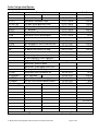
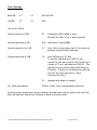
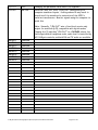
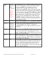
Radio Configuration/Options:
Model #
Description
Cost $
K3
KAT3-F
KFL3A-1.8k
KFL3A-400
KRX3-F
KDVR3
KUSB
Radio 100 Watt
Automatic Antenna Tuner
1.8 kHz 8 Pole Roofing Filter
400 Hz 8 Pole Filter
2nd Receiver
Digital Voice Recorder
Universal Serial Bus Adapter
07-07-2008
07-07-2008
07-07-2008
07-07-2008
07-07-2008
07-07-2008
07-07-2008
2089.95
329.95
125.00
125.00
599.95
99.95
39.95
KPA3
KXV3A
KPCA-F
PR6
12 Volt Sense Modification Labor
RX Antenna IF Out & Xverter Int
Power Cable
6 Meter Low Noise Pre-Amp
04-07-2010
04-07-2010
04-07-2010
04-07-2010
99.00
109.95
14.95
149.95
LPA
Heat sink pads
03-06-2013
8 volt regulator filter capacitor
Upgraded 8.215 trap on KAT3 with robust components
Gold Pins: KPAI03 Riser
Gold Pins: Front panel P30 & P35
Factory calibrate & align
K3SSKT
Stainless Steel Hardware Kit
03-06-2011
K3SSPUPGD
DSP Upgrade
03-06-2013
K3STFNR
Synthesizer Stiffener Upgrade
03-06-2013
K312MDKT
12 VDC Out Current Modification
03-06-2013
Labor for upgrades
03-06-2013
19.95
109.95
19.95
8.00
222.75
$4,164.20
I believe all available upgrades/modifications have been completed by Elecraft technicians.
C:\My Documents\Ham\Equipment\Elecraft\Elecraft K3 General Notes.doc
Page 5 of 112
Modifications & Updates:
Extreme Signal Protection
IF Output Buffer
KSYN3 Filter Terminator
Added C101 on front panel
Replaced AF/RF gain knobs
Current Software
C:\My Documents\Ham\Equipment\Elecraft\Elecraft K3 General Notes.doc
Page 6 of 112
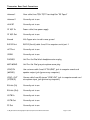
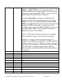
Transceiver Rear Panel Connections:
Antenna 1
Coax cable from TEN-TEC Titan Amplifier “RF Input”
Antenna 2
Currently not in use
AUX RF
Currently not in use
12 VDC In
Power cable from power supply
12 VDC Out
Currently not in use
Ground
# 6 Copper wire to radio room ground
RS232 Port
RS232 (Serial) cable from K3 to computer serial port 1
ACC Port
Currently not in use
SPKRS
Currently not in use
PHONES
Heil Pro-Set Plus! black headphone stereo plug
MIC MONO
Heil Pro-Set Plus! gray microphone mono plug
LINE-IN
(MONO)
Use a stereo cable from K3 "IN LINE" jack to computer sound card
speaker output jack (green on my computer)
LINE – OUT
(STEREO)
Stereo cable from K3 stereo "LINE-OUT jack to computer sound card
microphone input jack (pink on my computer)
RX Ant (In)
Currently not in use
RX Ant (Out)
Currently not in use
XVTR In
Currently not in use
XVTR Out
Currently not in use
IF Out
Currently not in use
C:\My Documents\Ham\Equipment\Elecraft\Elecraft K3 General Notes.doc
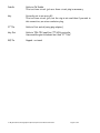
Page 7 of 112
Paddle
Cable to CW Paddle
This is a three-circuit jack so a three circuit plug is necessary.
Key
Currently not in use on my K3
This is a three-circuit jack, but the ring is not used thus if you wish to
this connection, use a two conductor plug.
PTT In
Cable to Foot switch (using plug adapter)
Key Out
Cable to TEN-TEC amplifier PTT/VOX controller
Some would argue this should be titled “PTT Out”
REF In
Capped – not used
C:\My Documents\Ham\Equipment\Elecraft\Elecraft K3 General Notes.doc
Page 8 of 112
Headset & Microphone Information:
One can connect the Heil Pro-Set Plus! to the K3 front panel to the K3 rear panel.
If using the Heil AD-1 (Kenwood/Elecraft Red Adapter Cable) the headset 1/8” gray mono
plug connects into the AD-1, which is connected to the K3 front panel “MIC” connector.
If not using the AD-1 (Kenwood/Elecraft Red Adapter Cable), the Heil Pro-Set Plus! headset
1/8" gray mono plug connects to the K3 rear panel "MIC MONO" connector. The Heil Pro-Set
Plus! headset 1/8” black stereo plug connects to the K3 rear panel “PHONES” connector.
To properly program the K3 to use the Heil Pro-Set Plus!:
Turn the K3 "On".
Press the “MODE” button until USB is displayed in the upper right of the K3 display.
Briefly press the “MENU/CONFIG” button and “MAIN” will briefly display on the K3 display.
Turn the "VFO B" knob until “MIC SEL” is displayed on the K3.
If using the AD-1 adapter cable, turn the "VFO A" knob until “FP.L” is displayed.
If using the K3 rear panel connections, turn the "VFO A" know until "rP.L" is displayed.
The "H" or "L" refers to the microphone gain range and *not* to the bias level. You may want
to try the low range to have more control over your microphone gain (your microphone level
setting will require higher numbers).
Briefly tap the “A/B” / 1” button and select .L as the microphone gain.
Briefly tap the “REV / 2” button to set “BIAS” to “off” (it is "off" when the word "biAS" is
not displayed.
Continue to turn the VFO A knob until you reach:
Set
“VOX GN”
50
Briefly press the “MENU” button and the settings will be stored in memory.
Press and hold the “MENU” button to access the “Config” menu selections.
Set
“AF Gain”
High
If you wish to hear through both the Heil headset and the internal K3 speaker at the same
time, make the following “Config” selections:
C:\My Documents\Ham\Equipment\Elecraft\Elecraft K3 General Notes.doc
Page 9 of 112
Set
Set
“SPKRS”
“SPKR+PH”
2
Yes
Settings depend on one's voice and how you want to sound. Here are the settings I am
currently using:
The MIC Selection was set on the previous page using the "MENU" system.
The "Speed / MIC / Delay" knob will set to "MIC" (green light will display) is used to set the
Mic Gain.
The "CMP/PWR/MON" knob will be used to set the Compression value.
The "VOX Gain" is set with the "MENU" system.
The "VOX Delay" is set with the "Speed / MIC / Delay" know by pushing the knob and holding
it until the "VOX Delay" setting is displayed.
Mic Gain Range
Mic Gain
Comp
VOX Gain
VOX Delay
Heil
FP.L
20
12
050
0.50
The rear panel microphone jack is a stereo (T-R-S) jack with the mono audio mic signal
connection on the tip and the shield should be connected to the shell. The ring is not
connected. It is an unbalanced input and accepts balanced or unbalanced dynamic mics but
only unbalanced electret condenser mics. When RL.X bias is on, it supplies 8 volts.
Mic Gain and VOX Setup
Follow the instructions on pages 28 and 29 of the K3 Operating Manual. There are many
inter-dependent adjustments on the K3, and the setup instructions on those pages are
excellent.
C:\My Documents\Ham\Equipment\Elecraft\Elecraft K3 General Notes.doc
Page 10 of 112
Heil published the following information in their website article, “DSP Settings and Mic
Connections: Elecraft K3.
DSP Settings and Mic Connections: Elecraft K3
Note: These are starting points only. The best setup for your voice, your microphone, and
your operating objectives may differ. Be sure to listen to yourself on a separate receiver
(with its antenna disconnected and noise blanker turned off) as you make final adjustments
to optimize the settings for your operating situation.
Connections:
The K3 utilizes the Kenwood protocol for connections to its front panel 8-pin microphone
jack, so use the CC-1-K adapter for 4-pin XLR microphones (GM Series, HM-10 Dual, and
Handi Mic), and use the CC-1-XLR-K adapter for connection to 3-pin XLR microphones (PR781, etc.).
Briefly press the “Menu” button on the K3 front panel so you will be placed in the “Main”
menu selections. Set the “MIC SEL” menu selection to “FP.L” (Front Panel).
See pages 13, 17 and 20 of the K3 Operating Manual for more details.
What Kind of Mic?
Most operators will be connecting a dynamic element microphone (HC-4, HC-5, or PR781 type). In this case, while setting up the MAIN: MIC SEL menu, tap [1] to toggle to
"LOW" Mic Gain, and be absolutely certain that Mic Bias is off by tapping [2], as
needed, to toggle to "OFF" for Mic Bias. My microphone is the Heil Pro-Set Plus and these
are the settings I use.
If you are connecting to an "iC" element (Pro Set iC, Pro set Plus iC, Pro Set Elite iC,
Handi Mic iC, or the iCM via the HSTA-K8 adapter cable), tap [1] to select "HIGH" Mic
Gain, and tap [2] to set the Mic Bias to the "ON" option. See pages 13 and 20 of the K3
Operating Manual.
Eight-Band Equalizer Settings
The K3 includes a versatile 8-band transmit equalizer, which is adjusted separately from the
receiver equalizer. The K3 also has an "ESSB" mode, with a wider transmitted bandwidth for
high fidelity operating. Please read pages 35-36, and page 60, of the K3 Operating Manual, in
particular, for more details of these subjects. Yes, you have to read the manual!
C:\My Documents\Ham\Equipment\Elecraft\Elecraft K3 General Notes.doc
Page 11 of 112
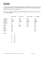
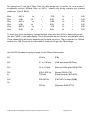
The table that follows details starting points for operation using two main categories of
mics: the "articulated" elements (HC-4 and HC-5 based mics), and the "wide range" elements,
typified by the iCM, Handi Mic iC, and PR 781 and the PR 20/30/40 genre. Remember to set
the Mic Gain and Mic Bias properly, as described above.
Eight Band Equalizer Starting Points
Freq > 0.05 0.1 0.2 0.4 0.8 1.6 2.4 3.2
HC-4/5 -10 -4 -2 0 0 +2 +4 +4
Wide -12 -10 -6 -2 0 +6 +8 +10
The above settings are for "normal" operation. For ESSB operation, you may want to set the
lower-frequency selections to positive settings, depending on which microphone you have and
your audio sound objectives.
Again, these are necessarily starting points for operation, and it should be noted that, when
using the HC-4 and HC-5 elements, the equalizer may be left at its default setting of "0"
across the board, since equalization is already taking place in the mic element itself.
C:\My Documents\Ham\Equipment\Elecraft\Elecraft K3 General Notes.doc
Page 12 of 112
COM Port Information:
The K3 rear panel RS232 port is connected to my computer COM Port 1 via a 9 pin serial
cable.
If you use the USB / Serial adapter from Elecraft, it is probably an FTDI device.
Disconnect your cable from the computer, install the correct driver and after the driver
installs, then plug in the cable. After you plug in the cable, go back into Control Panel and see
what com port # Windows has assigned to your adapter. Set your software to match that
com port number.
It is strongly recommended to not use a Prolifics-based device as they are known to cause
problems with N1MM Logger (and any other software developed with VB6). It is suggested
that you use an FTDI-based USB/serial converter. If it is an FTDI, you can go here and
download the correct driver:
http://www.ftdichip.com/Drivers/VCP.htm
COM Port Sharing:
The K3 has a single RS-232 (COM) port. When you wish to use the computer to K3 COM port
connection for general and/or contest logging software as well as CW, PSK, and RTTY, the
single hardware COM port on the K3 limits your ability to have multiple COM ports talking to
the K3, thus you need a hardware interface or a software solution.
The next page tells how to obtain the software in use for “Virtual” COM port operation and
how to configure it.
C:\My Documents\Ham\Equipment\Elecraft\Elecraft K3 General Notes.doc
Page 13 of 112
Software:
I use the N1MM Logger© program when contesting and the DX4Win© logging program for
day-to-day contact logging. I discovered LP-Bridge, a software solution, which allows me to
use the single K3 RS-232 (COM) port while operating multiple programs at the same time
using “Virtual” COM ports.
LP-Bridge Software:
Another ham suggested I consider the use of “LP-Bridge” © software written and supported
by Larry M. Phipps, N8LP. The software is provided as “Freeware” on his website located at:
http://www.telepostinc.com/LPB.html.
According to information posted on Larry’s website, the LP-Bridge software is unique as it
creates a mirror K3 in the computer’s memory, with constantly updated data about the
current state of the hardware.”
Your first step should be to set your K3 to 38400 baud. This is accomplished by pressing and
holding the “Menu” button on the front of the K3 until the “Config” window is displayed. Turn
the VFO “B” knob clockwise until “RS232” is displayed and then turn the VFO “A” knob
clockwise until “38400 b” is displayed. Finally, press the “Menu” button again to set these
parameters.
Using Microsoft’s Internet Explorer browser software or your personal choice of browser, go
to http://www.telepostinc.com/LPB.html where you will find Larry provides a simple “click and
download” capability of a “ZIP” type file so it is easy to obtain the software via the Internet
Once the software is downloaded to your computer, extract the files into a temporary folder
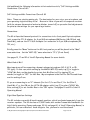
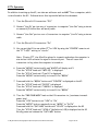
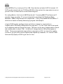
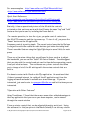
and then run the software to install it on your computer. The LP-Bridge program will display
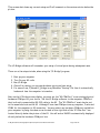
a screen similar to the one shown below. Note: Default data has been modified in the
picture shown in order to work on my computer.
C:\My Documents\Ham\Equipment\Elecraft\Elecraft K3 General Notes.doc
Page 14 of 112
This screen shot shows my current setup and I will comment on the various entries below the
picture.
The LP-Bridge software will remember your setup of virtual ports during subsequent uses.
There are a few steps to take, when using the “LP-Bridge” program.
1.
2.
3.
4.
5.
Boot up your computer
Turn On your K3 radio
Run LP-Bridge
Once all is running, you can use whichever ports you have setup.
For ease of use, I placed LP_Bridge in my Windows “Startup” file thus it automatically
loads each time the computer is turned on.
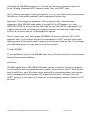
Note on the LP-Bridge screen display, you must set the “K3 COM Port” to an existing physical
hardware COM port of your choice. Set the LP-Bridge software to the computer COM Port
that is directly connected by RS-232 cable to the K3. The “K3 COM Port” must also be set
to the same baud rate as the K3. Although I have two COM ports on my computer, I selected
COM1 for the computer to K3 connection. You may select any hardware COM port available in
your computer by using the down arrow located on the right side of the “K3 Com Port” box
located directly below the picture of the K3. You will notice 38400 is automatically displayed
directly below the hardware COM port box.
C:\My Documents\Ham\Equipment\Elecraft\Elecraft K3 General Notes.doc
Page 15 of 112
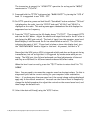
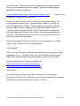
Your next step is to use your mouse and left click on the “Connect” box, which is also located
directly below the picture of the K3. If your radio is set properly to 38400 baud and you
have selected an actual hardware COM1, COM2, COM3, etc. the “Connect” window will change
to “Disconnect” and data showing the status of your K3 will be displayed in the far right
column of the LP-Bridge window in the area titled “K3 Rcvd Text”.
The LP-Bridge software will remember your setup of virtual ports, when used the next time.
There are a few steps to take, when using the “LP-Bridge” program.
It is now time to setup up one or more “Virtual” Com Ports using the LP-Bridge software.
During my installation, I setup as follows:
“Virtual Com Port #1” to be COM 5 from which I operate DX4Win
“Virtual Com Port #2” to be COM6 from which I operate CW
“Virtual Com Port #3” to be COM7 from which I operate PSK
“Virtual Com Port #4” to be COM8 from which I operate N1MM
You will setup your system to accommodate your requirements.
C:\My Documents\Ham\Equipment\Elecraft\Elecraft K3 General Notes.doc
Page 16 of 112
Software In Use:
N1MM Logger©
Logging software
This software is available from:
http://www.n1mm.com
DX4Win©
Logging software
This software is available from:
http://www.dx4win.com
Instructions for the use of PSK and RTTY are provided elsewhere in this document.
Some of the software I use for various functions is shown below:
CW Decoder XP©
Send and receive computer assisted CW
This software is available from:
http://www.ac6v.com/morseprograms.htm
MMTTY©
Send and receive computer assisted RTTY
This software is available from:
http://mmhamsoft.amateur-radio.ca/mmtty/
N1MM©
Contest log program
This software is available from:
http://www.n1mm.com
WinPSK©
Send and receive computer assisted PSK
This software is available from:
http://www.qsl.net/w2va/freeware.htm
C:\My Documents\Ham\Equipment\Elecraft\Elecraft K3 General Notes.doc
Page 17 of 112
Instructions for the setup of each of these programs is available on my website:
www.n3me.net/howto.htm.
Each software program must be installed on your computer and during the setup of each,
select the COM Port of your choice and then tell LP_Bridge, which “Virtual Com Port” port
matches the software COM Port requirement. You may select any COM port number as long
as it is not an actual hardware COM port you may have installed in your computer. Remember,
you only need one real hardware COM port in order to use this software. The “Virtual Com
Port” selections are not real computer hardware COM ports.
C:\My Documents\Ham\Equipment\Elecraft\Elecraft K3 General Notes.doc
Page 18 of 112
Power “Gain” Calibration:
The following comment comes from an e-mail dated February 26, 2009 written by Wayne,
N6KR.
There isn't any "100 W calibration" on the K3. All gain calibration is done at 5 and 50 W (and
optionally 1 mW if you have a KXV3). To calibrate the rig is at any setting from 13 to 100 W
depends on whether you've done the 50 W calibration.
There is one additional form of optional calibration: the K3's wattmeter.
See CONFIG:WMTR in the owner's manual.
There is a procedure on page 49 on the K3 manual to calibrate the power out on the K3.
After doing this you calibrate "per-band" using a procedure on the same page. The K3 power
meter is not absolute. In other words, this procedure on page 49 is what tells the K3 power
meter how much 100 watts really is (actually 50 watts is used for the test).
C:\My Documents\Ham\Equipment\Elecraft\Elecraft K3 General Notes.doc
Page 19 of 112
CW Operation:
Wayne (N6KR) provides the following for anyone using the K3 to decode CW. "If you're
seeing E's and T's, try using a much narrower bandwidth, 50-150 Hz, and turn on the noise
blanker to reduce the level of impulse noise. I recommend using THR 2 or 3 for most signals,
and THR 1 for very weak signals. These fixed settings usually work better than AUTO.
When there is no CW signal above the required threshold, you'll see random characters
decoded.
I am using CW Decoder XP software to send and receive CW. A description of this software
is provided earlier in this document.
C:\My Documents\Ham\Equipment\Elecraft\Elecraft K3 General Notes.doc
Page 20 of 112
RTTY Operation:
In addition to setting up the K3, can also use software such as MMTTY on a computer, which
is interfaced to the K3. Information on this is provided within this document.
1. Turn the Elecraft K3 transceiver “Off”.
2. Connect “Line In” port on rear of transceiver to computer “Line Out” using a stereo
or monaural (I think either will work) cable.
3. Connect “Line Out” port on rear of transceiver to computer “Line In” using a stereo
cable.
4. Turn the Elecraft K3 transceiver “On”.
5. You can set the K3 to use either PTT or VOX by using the "CONFIG" menu to set
the “PTT—KEY” setting to "rts-dtr".
Note: If using PTT, the K3 will be placed in transmit mode when the computer is
started as it will activate the signal in the serial port. This will cause the
transceiver to key, when the computer is turned on.
6. Press the “MENU” button briefly and “MAIN” will display on K3
Turn the “VFO B” knob until “MIC SEL” is displayed
Turn the “VFO A” knob until “Line In” is displayed
Press the “MENU” button briefly to turn off the “MENU”
7. Press and hold the “MENU” button until “CONFIG” is displayed on the K3
Turn the “VFO B” knob until “RS232” is displayed
Turn the “VFO A” knob until “38400 b” is displayed
Press the “MENU” button briefly to turn off the “MENU”
8. Turn the “CMP/PWR/MON” knob on the K3 transceiver to ½ maximum transmit
power level
Press the “VOX” button to set “VOX” to “On”
Press the “MODE” button repeatedly to set “MODE” to “DATA”
Press and hold the “DATA MD” button until “45 bPS” is displayed on the K3
Turn the “VFO B” knob until “AFSK A” (defaults to LSB) is displayed on the K3
Briefly press and release the “DATA MD” button
C:\My Documents\Ham\Equipment\Elecraft\Elecraft K3 General Notes.doc
Page 21 of 112
The transceiver is now set for “AFSK RTTY” operation for as long as the “MODE”
remains set to “TX DATA”.
9. Press and hold the “PITCH” button and set “MARK/SHIFT” by turning the “VFO A”
knob. It is suggested to use “2125 – 170”.
10. For RTTY operation, press and hold the K3 “Data Mode” button and when “TX Data”
is displayed on the radio, turn the “VFO B” knob until “AFSK A” and “45 bPs” is
displayed on the radio. This setting uses upper sideband and the dial displays the
suppressed carrier frequency.
11. Press the “TEST” button so the K3 display shows, “TX TEST”. Then transmit RTTY
and view the ALC Meter. Adjust the sound card output level and/or the K3's line in
gain (using the MIC gain control). The level of input from the computer sound card
should display 4 solid bars and the 5th bar should blink on and off. The fifth bar
indicates the onset of ALC. If your level is below or above this display level, turn
the “CMP/PWR/MON” knob to adjust to this level. At present, the level is “6”.
Now adjust the VOX gain so VOX is triggered reliably and does not drop out during
transmissions, but not so high that it is triggered by random noise while you are
tuning. The VOX gain, Line-In level and sound card level adjustments all interact
and they are different for different sound cards and different radios.
When the level is set correctly, press the “TEST” button to return the K3 to “TX
NORM”.
Note: You may need to increase the computer sound card output volume. Do this in
stages until you find the correct setting for your computer/radio combination.
Note -- if you have more than one sound card, the normal volume settings displayed
apply only to the default soundcard. You must use the Control Panel to temporarily
change the default soundcard to adjust the controls on the second sound card, and
then change the default back.
12. Select the desired filter(s) using the “XFIL” button.
C:\My Documents\Ham\Equipment\Elecraft\Elecraft K3 General Notes.doc
Page 22 of 112
PSK Operation:
1. Turn the Elecraft K3 transceiver “Off”.
2. Connect “Line In” port on rear of transceiver to computer “Line Out” using a
monaural cable.
3. Connect “Line Out” port on rear of transceiver to computer “Line In” using a stereo
cable.
4. Turn the Elecraft K3 transceiver “On”.
5. You can use either PTT or VOX by setting the K3 “CONFIG PTT—KEY” to rts-dtr.
If using PTT, the K3 will be placed in transmit mode when the computer is started
as it will activate the signal in the serial port. Note this will cause the transceiver
to key, when the computer is turned on, thus it is recommended to set VOX on.
6. Press the “MENU” button briefly and “MAIN” will display on K3
Turn the “VFO B” knob until “MIC SEL” is displayed
Turn the “VFO A” knob until “Line In” is displayed
Press the “MENU” button briefly to turn off the “MENU”
7. Press and hold the “MENU” button until “CONFIG” is displayed on the K3
Turn the “VFO B” knob until “RS232” is displayed
Turn the “VFO A” knob until “38400 b” is displayed
Press the “MENU” button briefly to turn off the “MENU”
Turn the “CMP/PWR/MON” knob on the K3 transceiver to ½ maximum transmit
power level
Press the “VOX” button to set “VOX” to “On”
Press the “MODE” button repeatedly to set “MODE” to “DATA”
Press the “TEST” button so the K3 display shows, “TX TEST”. Then transmit PSK
and view the ALC Meter. The level of input from the computer sound card should
display 4 solid bars and the 5th bar should blink on and off. The fifth bar indicates
the onset of ALC. If your level is below or above this display level, turn the
“CMP/PWR/MON” knob to adjust to this level. At present, the level is “6”.
It has been suggested that the "SPEED/MIC" control should be set to level "8" for
digital modes. Try this
C:\My Documents\Ham\Equipment\Elecraft\Elecraft K3 General Notes.doc
Page 23 of 112
When the level is set correctly, press the “TEST” button to return the K3 to “TX
NORM”.
For PSK31 operation, press and hold the K3 “Data Mode” button and when “TX Data”
is displayed on the radio, turn the “VFO B” knob until “Data A” is displayed on the
radio.
"DATA A"
• Typically selects audio from the line in jack and mutes the microphone, thus one
does not incur background noise and/or hum from the microphone interfering with
the modulation or causing broadband interference to others
• Disables TX Equalization so audio levels are not up/down depending on where in
the transmit passband one is operating
• Compression is automatically set to zero, RX equalization is turned off, input level
can be set to "Line In" and the level remembered so it is automatic once set up
• Changes the "scale" of the "ALC Meter" (expanding the range around the fourth
(4th) bar position) so it is much easier to set the correct modulation level for
optimum audio input
• Uses upper sideband and the dial displays the suppressed carrier
8. Select the desired filter(s) using the “XFIL” button.
9. Once you have accomplished steps 1 – 8, you are ready to load the digital software
of your choice for PSK operation.
Note: You may need to increase the computer sound card output volume. Do this in
stages until you find the correct setting for your computer/radio combination.
Note -- if you have more than one sound card, the normal volume settings displayed
apply only to the default soundcard. You must use the Control Panel to temporarily
change the default soundcard to the secondary sound card to adjust the controls on
the second sound card, and then change the default back.
Use the "WIDTH" knob to expand the bandwidth waterfall. NEED TO TRY THIS!
C:\My Documents\Ham\Equipment\Elecraft\Elecraft K3 General Notes.doc
Page 24 of 112
PSK Programming Mode Information:
The Elecraft K3 has separate PSK, AFSK and FSK modes.
The K3 needs to be operated in extended CAT mode (K31 On). The CAT "data" modes are
"normal" (MD6;) and Reverse (MD9;)
The data submode is set with the DT; where:
DATA A = DT0
AFSK A = DT1
FSK D = DT2
PSK D = DT3
; Note: PSK D is only useful with the KY; command.
For FSK D and AFSK A, "normal" is LSB and "reverse" is USB.
For Data A and PSK D, "normal" is USB and "reverse" is LSB.
The data submode is indicated in the 35th byte of the IF response.”
When using PSK31 and similar modes, the K3 VFO A is set to a frequency for the carrier.
The audio is on the upper sideband, and is centered in the 3 KHz passband which is 1.5 kHz up
from the carrier - thus the offset.
C:\My Documents\Ham\Equipment\Elecraft\Elecraft K3 General Notes.doc
Page 25 of 112
SSB Operation:
SSB Audio - To properly adjust the audio into the K3, check that the ALC meter is lighting up
5 to 7 bars with normal speech. If not, set the compression to zero (1:1) and use “TX TEST”
so you don’t transmit. Adjust the “SPEED/MIC/DELAY” (microphone gain) knob so the ALC
meter indicates at least 5 bars and peaks at 7 bars. When this process is complete, increase
the compression as desired after which you turn off “TX TEST”.
To properly adjust the power output for CW or Digital use the Mode button to select the
mode you wish to set and the “SPEED/MIC” button to view and adjust the MIC or Line Out
power/drive. The settings will display on the "RF" bar graph in the display window.
To make the MIC adjustment for CW or SSB, place the K3 in CW, LSB or USB Mode, press
the “SPEED/MIC/DELAY” knob twice and adjust the power output while watching the display.
My “SPEED/MIC/DELAY” control is set to 8 for digital modes and 20 for SSB/CW.
For voice modes, first turn off compression, then go up until the 7th bar flickers. After
setting the audio level, then add back compression as desired. These steps should be done in
“TX TEST” so no RF is transmitted.
The display is not an indication of ALC action or compression. The ALC does not start until
the 5th or 6th bar is illuminated - the lower 4 bars are an indicator of the audio level (sort
of like a Vu meter).
C:\My Documents\Ham\Equipment\Elecraft\Elecraft K3 General Notes.doc
Page 26 of 112
ATU Operation:
The KAT3 ATU mode is normally set to BYP (Bypass) or AUTO (Automatic) outside the menu.
ATU alternates between the two modes.
Modes L1-L8, C1-C8, and Ct are used to test KAT3 relays.
Mode LCSET allows manual adjustment of L/C/net settings (you must exit the menu first).
When in LCSET mode, tapping ATU TUNE shows the L and C values; C is changed with VFO A,
L is changed with VFO B, and ANT toggles between Ca and Ct .
Tapping CLR within this menu entry clears stored LC data for the present band.
The following provided by Fred Jensen (K6DGW):
“"Automatic" is a word with lots of meanings. When it is in "AUTO" and you tap ATU TUNE,
it will "automatically" find a match using the power you have set in CONFIG:TUN PWR. Mine
is set to 5W. It then "remembers" the L/C settings for that band segment for the ANT
selection you are using [1 or 2]. The next time you are in that band segment using that ANT
selection, it recalls the settings the first time you transmit [PTT or KEY].
Push the ATU TUNE button once to get a quick but somewhat rough SWR match. If you push
ATU TUNE a second within 5 seconds of the first pass completing, the ATU will take more
time and come up with a better SWR match.
The band segment sizes depend on the band. I believe they are:
160: 10 KHz
80-12: 20 KHz
10: 100 KHz
6: 200 KHz
You can just let the memorized settings accrue as you operate normally, or you can
methodically go through the bands and set them all. I did the latter, tuning to the middle of
each segment with the antenna I normally use, and tapping ATU TUNE. Seems to work really
good.”
C:\My Documents\Ham\Equipment\Elecraft\Elecraft K3 General Notes.doc
Page 27 of 112
It is also engaged/bypassed per band per antenna according to the remembered setting on
that band/antenna combination.
C:\My Documents\Ham\Equipment\Elecraft\Elecraft K3 General Notes.doc
Page 28 of 112
AGC Discussion:
AGC means automatic gain control and its function is to keep the receiver's audio output
more or less constant as the RF input signal changes level.
It is suggested to use slow AGC during a contest perhaps set to its fastest setting – this will
keep the loud signals linearly loud and short enough to recover when the loud station is
worked and moves off frequency.
Dave Hachadorian (K6LL) suggests,
1. Dedicate an F-Key in your logging program to turn off agc whenever a loud pileup shows up.
Turn it off on both rigs if you are so2r. In N1MM, the macro is:
{CAT1ASC SWH027;}{CAT2ASC SWH027;}
2. Add to the "exchange" message a command to turn fast agc back on (for both rigs in so2r).
In N1MM, the macro is:
{CAT1ASC GT002;}{CAT2ASC GT002;}
The effect of the above is that agc is turned off, and gain is reduced, only while you are
struggling to pick a callsign out of a loud pileup. As soon as you send the exchange, fast agc is
restored, and gain goes back up on both rigs.
The following is a quote from an e-mail written by Wayne, N6KR and Lyle, KK7P on February
25, 2009.
Details:
Some operators described a "merging" of multiple, close-spaced signals when listening to
pileups, making individual signals hard to copy. Assuming that a narrow crystal filter is in use
(close to the DSP bandwidth), this is not "desense". In most cases, we've discovered, the
cause is IMD (intermodulation distortion) related to the AGC algorithm.
To simulate what happens under pileup conditions, we combined four crystal oscillators with
gaps between them of 5, 6, and 7 Hz (a total spread of 18 Hz for the four signals). We then
injected the signals into the K3 at an equal level of about S5 and used spectral analysis to
examine what happens to the passband. With AGC-F turned on (AGC fast, set to the K3's
factory defaults), IMD products came up some 20-25 dB as compared to AGC OFF. The
situation could be far worse in an actual on-air situation with more signals, noise, and key
C:\My Documents\Ham\Equipment\Elecraft\Elecraft K3 General Notes.doc
Page 29 of 112
clicks. (AGC-S makes only a small improvement.) We ran the same test on several other
radios, and verified the AGC-induced IMD characteristics are similar.
IMD is generated because AGC can cause mixing between the tones and their harmonics. The
faster the decay rate, in general, the more products will be generated. With just one or two
signals, most products will be outside the DSP's narrow IF or AF passband. But in a pileup,
where signals are greater in number and can be nearly on top of each other, there are many
more opportunities for signals to combine. This results in IMD products spaced at 1 to 20 Hz,
depending on the time constants, location of the signals, etc.
Turning AGC off is one strategy that operators have traditionally used to combat the
effects of AGC modulation. It then becomes necessary to "ride" the gain controls. Neither
Lyle nor I have that much patience :) so we took a different approach: keep the AGC on, but
reduce its modulation effects to negligible levels by adding a very long "hold"
time.
In the field-test firmware, two changes have been made. First, the AGC HLD menu setting,
which used to apply only to voice modes, now applies to CW as well. (It still only affects AGCS, the slow AGC setting.) Second, we increased the range of AGC HLD to facilitate
experimentation. What we found is that an AGC hold time of about 1 second, combined with a
slower AGC-S decay time, reduces in-band IMD with closely spaced signals by 20-25 dB,
making it very similar to turning AGC off. The *attack* time is unaffected, so there is no
"thumping" as you might have with audio-derived AGC. Any new signal peak above the one that
starts the "hold" timer will restart the timer.
This "hold" AGC appears to be useful in many listening situations. It can make voice signals
sound cleaner, as well; after all, a voice signal can have many components, and AGC-induced
modulation can add IMD products. It also helps with noisy band conditions.
The down side to AGC "hold" is that large signals can charge it up to a high level, reducing
gain for the duration of the hold time. But in many cases this is far preferable to the AGC
IMD effects, especially if you're listening to many signals at similar amplitudes -- as in a
pileup.
You'll want to play around with agc slope and threshold. I settled on a slope of 10 and
threshold of 8. Discover what settings you prefer. Don't forget the receive equalizer either
which is a very nice feature. I've found not all speakers or phones sound the same. It's nice
to tweak them with the equalizer.
C:\My Documents\Ham\Equipment\Elecraft\Elecraft K3 General Notes.doc
Page 30 of 112
The following was written by Bill W4ZV:
Note that Eric's setup is for AGC Off, which is probably not a good idea for most casual
users. I would start with AGC-F using the default AGC Menu settings. You can check the
defaults for each CONFIG: AGC Menu by tapping the DISP button while in the appropriate
CONFIG Menu (all AGC settings begin with CONFIG: AGC xxx, and remember that some are
only accessible with CONFIG: TECH MD On).
1. Have available your desired antenna and a dummy load (both on a coax switch is ideal) for
each band you want to set up (you'll at least need to do this for major segments like 80/160,
40-18, 15-10 and 6 separately (if you have the external preamp).
2. Set AF GAIN back to about 9 o'clock and RF GAIN to MAX (fully clockwise). This assumes
you have the proper AF GAIN menu setting for your specific headphones ( I use AF GAIN LO for my 32 ohm headphones and still have tons of audio).
3. In the following order (first ATT ON, then ATT OFF, then PRE ON) alternately switch
between your antenna and the dummy load. When you hear noise increase when switching to
the antenna, use the lowest gain setting (i.e. ATT will likely be the correct setting on the
noisy low bands and PRE will likely be correct for 10m). Remember that the K3 will remember
these settings for each band. Once you have the correct setup on each band it will
automatically recall that PRE/ATT setting when you return to that band.
4. Now adjust the RF GAIN knob counterclockwise until the antenna noise on the meter just
stops flickering on the meter. This will be familiar to OTs since this is the way we set RF
GAIN many years ago on analog radios.
5. Now adjust your AF GAIN knob for a comfortable listening level (mine is normally 9-10
o'clock which may vary depending on what type of headphones you have).
If you still don't like the amount of background noise compared to signal levels, adjust
CONFIG: AGC THR to a lower setting than the default 5. This which will reduce the apparent
noise level by moving the AGC onset point down and acting as sort of a noise squelch.
Regarding settings for speakers, I never use them since I'm normally listening for extremely
weak signals on 160m or in contests and I don't want ANY extraneous noise between my ears
and the signals. Perhaps someone who uses speakers can add comments.
I hope the above helps but please read K3NA's article for more comprehensive suggestions
(remembering that his setup is for AGC Off).
C:\My Documents\Ham\Equipment\Elecraft\Elecraft K3 General Notes.doc
Page 31 of 112
My general rule for all gain settings (PRE/OFF/ATT, RF Gain knob, AF Gain knob, CONFIG:
AF GAIN) is LESS IS BETTER (as long as you can hear signals). This is contrary to the
thinking of some but following it will ensure that you get the ultimate dynamic range
performance available from the K3.
C:\My Documents\Ham\Equipment\Elecraft\Elecraft K3 General Notes.doc
Page 32 of 112
Further comments from Wayne (N6KR) on AGC:
The K3 provides two alternatives to turning off AGC in this situation.
We closely examined the effect of these on multiple close-spaced signals, and both reduce
IMD considerably:
1. CONFIG:AGC DCY sets the AGC decay characteristic, and applies to both AGC-S and AGCF (slow and fast AGC). The default setting NOR, provides a traditional linear decay. The
SOFT setting applies a "soft"
exponential decay. It typically reduces in-band IMD by 10-15 dB.
1. CONFIG:AGC HLD adds a "hold" timer to slow AGC-S (slow AGC) only.
It behaves as if you were manually (and very quickly) riding the RF GAIN control, reducing
gain when a very strong signal comes in, then turning it back up N seconds later. The normal
setting is 0.00 (no hold time); a typical setting for pileup conditions might be 0.40.
This can reduce in-band IMD as much as turning AGC off.
Andy (AE6Y/P49Y) makes the following comments:
“I would add that I have found that using AGC-S with SLP=6 and THR=6 gives me the abilty
in CW pileups to separate out the signals by riding the RF gain control, without turning off
the AVC and risking getting blown out by strong signals. I used these settings in WPX CW
this past weekend and found them very effective. It's hard to figure this out on the fly, but
I had tied varying the settings by listending to another stations's pileup a few contests ago.
The K3 is just a great run radio: unless the adjacent stations have clicks, you simply don't
hear them (though the P3 shows just where they are, if you want to optimize your frequency
between big signals).”
C:\My Documents\Ham\Equipment\Elecraft\Elecraft K3 General Notes.doc
Page 33 of 112
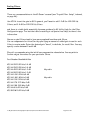
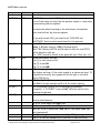
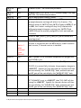
AGC Settings:
To modify the factory default AGC settings, press and hold the “Menu” button until “Config”
is shown on the K3 display. Turn the “VFO B” knob until “AGC DCY” is displayed. Then turn
the “VFO A” knob to the setting you prefer.
Dave, K6LL, and Ignacy, NO9E made the following suggestions for AGC settings for general
use in e-mail messages.
Bill, W2BLC
Dave, K6LL
Ignacy, NO9E
Tony, N3ME
AGC DCY
AGC HLD
AGC PLS
AGC SLP
AGC THR
AGC F
AGC S
Shift
Width
RF Gain
ATT
Norm
0.00
NORM
4
12
120
020
1.4
2.7
90
ON
Soft
0.20
NORM
0
8
200
020
Norm
0.50
NORM
010
005
150
020
Soft
0.30
NORM
012
005
120
020
1.4
2.7
90
ON
RX EQ
1
2
3
4
5
6
7
8
-2
0
+9
+12
+11
+14
-16
-16
C:\My Documents\Ham\Equipment\Elecraft\Elecraft K3 General Notes.doc
Page 34 of 112
Carrying Case:
A Mil-spec aluminum case (#138401) from Coleman's Military Surplus (www.colemans.com) is
available to accommodate an Elecraft K3 transceiver for heavy-duty transportation. Thanks
to Dave Olean, K1WHS, for finding this case and posting its availability to the Elecraft
reflector on November 13, 2009.
C:\My Documents\Ham\Equipment\Elecraft\Elecraft K3 General Notes.doc
Page 35 of 112
P3 Information:
Connection Considerations:
Someone said they were trying to install their new K3/P3 into their station, where they rely
on a > Navigator USB interface. The Navigator has a cable for "RS-232" and one > for "ACC."
That leaves no place to plug in the Panadapter. The Navigator RS-232 cable plugs into the P3
RS232 connector marked PC and the P3 (XCVR RS-232 connector) is connected to the K3 via
another RS-232 cable. The later cable is a male to female straight through type (RS232
Extender Cable). See page 13 of the P3 manual.
The Navigator RS-232 cable plugs into the P3 RS232 connector marked PC and the P3 (XCVR
RS-232 connector) is connected to the K3 via another RS-232 cable. The later cable is a
male to female straight through type (RS232 Extender Cable). See page 13 of the P3 manual.
Are you using the K3 Line In and Line Out connectors? If so, the Navigator must be
configured for line level output. You can check the audio input in TX Test mode - bring up
the audio drive (and the Line In gain) enough to illuminate 4 bars on the ALC meter (that is
NO ALC for the K3). The 5th bar might flicker a bit and that indicated the proper level.
C:\My Documents\Ham\Equipment\Elecraft\Elecraft K3 General Notes.doc
Page 36 of 112
C:\My Documents\Ham\Equipment\Elecraft\Elecraft K3 General Notes.doc
Page 37 of 112
Mailing List Guidelines:
Elecraft Mail LIST GUIDELINES
For those of you who are new to the list, (and for those of us who have rapidly failing
memories..), here is a quick list of things to remember when posting to this list. Please save
this for future reference.
The most important thing to remember is that this is only a hobby - Let's have fun!
1. YOU MUST BE SUBSCRIBED to the [Elecraft] list TO POST to it. (This is done to stop
advertising spammers from hitting the list.) Any postings sent to [email protected]
by addresses different from the exact ones it shows as subscribers will be rejected.
This includes alias (forwarded) addresses like [email protected]. If you use an alias to
subscribe you must have it as your from: and return address too.
Subscribing with [email protected] from your physical address of [email protected] will allow you to
receive postings, but your postings to the list will be rejected if their from: and reply to:
address does not match your subscribe address..
Go to http://mailman.qth.net/mailman/listinfo/elecraft to subscribe and to change your list
preferences. To unsubscribe or to change your list preferences (digest, no mail on/off etc.),
scroll to the bottom of the page and log in with your subscribed email address and the
password that was sent to you by email when you subscribed (and monthly afterwards.)
2. If you want to provide an attachment, .JPG picture or other large file for use on the list,
first post it to your personal web page and then post a link to its address in an email to the
list. The list strips all attachments to prevent viruses from propagating and to keep the
archives at a reasonable size.
3. Please keep your postings short and the amount of copied text from previous posts to an ABSOLUTE MINIMUM- in your replies.
Always delete everything from the prior post except what is necessary to keep your reply in
context.
Most copied messages can be reduced to one or two sentences to retain context.
Remember to delete the email list footer from the previous post.
C:\My Documents\Ham\Equipment\Elecraft\Elecraft K3 General Notes.doc
Page 38 of 112
Especially try to avoid copying a long prior posting and adding 'Me Too!' or something similar.
As the number of users on this list grows (over 3500 now) we need to work to minimize
information overload... If a reply is not of interest to the list, just reply directly to the
posting party.
4. EMAIL OVERLOAD:
If you are overloaded by the volume of individual messages on the list, you can view the
searchable daily Elecraft list messages for each month in web format at:
http://www.elecraft.com/elist.html . These archives are updated hourly and list all postings
by subject. Just click on the ones you are interested into read.
You can also set your list email preferences to 'no mail' delivery, which still allows you to post
to the list when reading via the digest.
You can also change your subscription to the DIGEST version, which sends you a single
compilation each day.
To change your email list options or to subscribe / unsubscribe, go to:
http://mailman.qth.net/mailman/listinfo/elecraft
Scroll to the bottom of the page to log into your preferences page and set your mail options
to 'no mail'.
4a. Please make an effort to keep list volume under control by resisting the urge to post a
comment on every long discussion thread (CW, Band Switching, and Soldering etc.) With over
3,000 list subscribers volume can quickly get out of control if everyone feels the need to
comment.
While we do not overly restrict the subject matter on this list, and we encourage postings on
a wide range of amateur radio related topics, please remember that the list's primary focus
is on Elecraft products and their use.
Many people rely on it for pointers on building, using and troubleshooting their Elecraft
products.
4b. *** [NEW] When emailing about a specific rig or option, please add the rig/option
name(s) to the first part of your email subject line. (K1, K2, K3,
KX1 etc.) This will be a huge help for those experiencing email overload and will allow
automatic filtering based on subject line.
Examples: "Subject: [K3] Filter Options"
C:\My Documents\Ham\Equipment\Elecraft\Elecraft K3 General Notes.doc
Page 39 of 112
"Subject: [KX1] How to use ped portable?"
"Subject: [XG2] Wow! It’s a big help.
5. *** IMPORTANT *** PLEASE KEEP ALL POSTINGS CORDIAL.
Restrain the urge to email someone admonishing them about a posting.
The last thing we want to do is to scare anyone off the list. Overly aggressive postings and
negative comments about other posters only serve to scare away new potential list members.
Waiting over night before hitting 'send' really helps to put things in perspective. Please make
all postings as if you were talking face to face to a close friend you do not wish to offend.
If you have a complaint about someone’s posting, spam or a thread topic please email directly
to me ( eric(at)elecraft.com ) and I'll address it.
Do not post your complaints to the list.
5a. Please -do not- post publicly or privately asking people to stop a particular thread, no
matter how long, off topic or repetitive it gets. Email me instead ;-).
I will step in when I feel it is necessary to end a thread. (eric(at)elecraft.com)
5a1. Please exercise restraint in posting when a thread is getting heavily covered. 10 to 20+
posts on one topic in a day are usually excessive. Please try to stop posting to any thread,
especially OT threads, once 10+ replies have been posted.
5b. Do not post any direct attacks or snide comments directed at a list member. Enthusiastic
arguments are encouraged, but please keep everything cordial. Members who verbally attack
another (either via the list or via direct email) will be removed from the list.
As the 'official' list moderator, I'll jump in as necessary to keep everything orderly. I do
this off line and occasionally to the list when it is appropriate. Our goal is to keep the
Elecraft list a fun, informative central clearing house for Elecraft information and
enthusiasm.
6. Please DO POST your technical questions and comments to the list.
Elecraft owners are your best source for quick answers (and they NEVER
sleep!) If you don't get the answers you need from the list please email us direct at
support(at)elecraft.com , which is our customer service address. We do try to watch the list
C:\My Documents\Ham\Equipment\Elecraft\Elecraft K3 General Notes.doc
Page 40 of 112
traffic, but we may not respond to everything immediately and may miss some postings sent
to the list or our personal addresses.
7. Please post your experiences with your Elecraft kit, DX worked, crazy ideas, product
ideas, complaints (yes - we do want to hear them). OT-Ham Radio Related posts are OK, but
please keep them short and focused. (See above about limiting OT thread replies.)
7. Commercial postings are allowed if they relate to Elecraft products, QRP, QRO, homebrewing, building etc. and are of interest to this list's membership. Please keep them as
short as possible and provide web links to more detailed information. I'll step in if we feel
someone is posting too many messages of this type.
7a. Please limit commercial postings to one per month per offering or product area (i.e.
Builder for Hire postings, ham radio related products etc.)
8. Once again, personal attacks, flames, or strongly worded derogatory messages will not be
tolerated. (Pausing overnight before pressing the send key really
helps..) Please do not criticize postings by others.
9. Send parts requests direct to parts(at)elecraft.com, not to the list.
(Replace '(at)' with '@' in this address.)
10. If you don't get an answer to a question from the list, or by checking the list archives,
don't forget to check the Builder's Resource Page at http://www.elecraft.com and our
support email addresses: support(at)elecraft.com
(non-K3 products) and k3support(at)elecraft.com (K3).
(Replace '(at)' with '@' in these addresses.)
11. And above all, LET’S HAVE FUN!. We hope that this list is both a good technical resource
and serves as an Elecraft community gathering place. We enjoy reading it every day and it
really helps us keep our energy level high so we can continue getting exciting new products
out the door to you!
73, Eric WA6HHQ
Elecraft List Moderator
C:\My Documents\Ham\Equipment\Elecraft\Elecraft K3 General Notes.doc
Page 41 of 112
Mailing List Password:
“If you have misplaced your Elecraft list password, or if you never received it, here is how to
get it sent to you again.
Go to: http://mailman.qth.net/mailman/listinfo/elecraft
and scroll to the bottom of the page. Enter your email address (the one you used for the list)
and click on 'Edit Options'. This takes you to your personal list options page. One of the
buttons on that page is labeled" 'Email my password to me'.
Once you have your password, go to the above link and enter it to change your subscription
parameters (digest mode, unsub etc.)”
73, Eric WA6HHQ
C:\My Documents\Ham\Equipment\Elecraft\Elecraft K3 General Notes.doc
Page 42 of 112
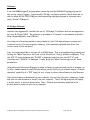
Noise Blanker:
Don Wilhelm (W3FPR) writes, “The K3 noise blanker… works by producing “holes” in the
receive path. That is what blanking means – if an impulse is detected, it shuts off the
receive path for a specified period of time.
That will not "take away" from the reception of faint signals, but if combined with gaps in the
received signals because of impulse events occurring at the receiving station, it may make the
copy of faint signals difficult because of the blanks in the received data stream.
In my opinion, it should only be used when necessary, not all the time.
If you have constant static pulses or automotive ignition noise or distant lightning surge
problems at your QTH, then it may be beneficial to run the NB at all times, but if you do not
need it, keep it off.
Remember that the NB responds to impulse noise - it will not be effective in reducing slow
rise time noise like atmospheric noise or power-line induced noise. NB needs a fast rise time
to be effective.
Noise reduction (NR) will reduce or eliminate things like atmospheric noise or power line noise
as it works on correlation principles. This means it is normally quiet while it looks for what
might be a valid signal. When it finds what appears to be a valid signal, it builds a filter
around it and sends the result to the K3 audio. What it looks for is highly dependent on the
parameters set for the K3 NR algorithm as well as your local noise. Experiment with your
chosen mode and local noise situation until you discover what works best for you. The
settings for CW will likely not be good for SSB. With NR on, the desired signal should be
enhanced, but really weak signals may be at or near the noise level, and may not appear as a
valid signal, giving the appearance that weak signals may be covered up and not detected. You
should normally run with the NR turned off and only use it when warranted.
Lyle (KK7P) provided the following information:
The K3 NR algorithm is a trade-off between noise reduction and stability.
The wider the dynamic range of signals presented to it, the more aggressive it must be,
which in turn makes it less useful for applying small amounts of noise reduction.
The NR pays some attention to the settings of AGC Slope and AGC Threshold. The higher
the Threshold, and the steeper the Slope, the more aggressive NR must be at its lowest
settings to prevent instability (SCREECH!!!!). We have chosen to make the NR somewhat
more aggressive in all cases to prevent instability.
C:\My Documents\Ham\Equipment\Elecraft\Elecraft K3 General Notes.doc
Page 43 of 112
Thus, if you have AGC Threshold set low and the Slope set to flat, the NR will be more usable
on weaker signals.
In the end, NR is a filter, and like any filter it will affect what is being passed through it.
The weaker the signal, the more it appears like noise and the harder it is to separate the
two.
Finally, NR is part of a general field of psychoacoustics. What some people like, others
barely tolerate. Somewhat like tastes in music...
We are always looking at ways of doing this better, and went through a very lengthy several
months ago to improve NR. You can be sure that we will revisit it when we review the status
of the K3 firmware and operation.
C:\My Documents\Ham\Equipment\Elecraft\Elecraft K3 General Notes.doc
Page 44 of 112
C:\My Documents\Ham\Equipment\Elecraft\Elecraft K3 General Notes.doc
Page 45 of 112
SSTV:
HRD/DM780 will try to set your K3 to SSB. Override that and select DATA A instead. K3
DATA modes automatically set TX EQ and RX EQ to flat and set the compression to zero so
you don't have to invent macros to turn those things off.
For analog (Martin, Scottie etc.) DM780 works well. I am using MMSSTV software and I
manually change rig modes. If you are interested in using Digital SSTV (Digital Radio
Mondale or DRM) things become a bit complicated. I don't think DM780 will do DRM as I
think this is almost exclusively done using a program called EasyPal.
A typical QSO involves sending pictures and often a comment or conversation on
frequency with SSB usually talking about the image sent. For this I use a macro that sends
at the beginning and end of each sent image. The macro at the start changes mode to Data A
and reduces power to about 70W. At the end it changes back to SSB and sets power to
100W. This process sends the image without compression or EQ. but then after sending
a picture I can just pick up the microphone and respond any comments. For receive I don't
have much EQ anyway so SSB is just fine for that.
C:\My Documents\Ham\Equipment\Elecraft\Elecraft K3 General Notes.doc
Page 46 of 112
Spurious Signal Removal:
In an e-mail written on May 26, 2009, Wayne, N6KR, addressed this with the following.
“The K3 is a very high-dynamic range, down-conversion superhet. It's nearly impossible to
remove all birdies in such a design. But we think we did a pretty good job of it :)
If you have any left (that you can hear with an antenna connected), you can "remove" them
using the SIG RMV menu entry in the CONFIG menu. Below are the instructions for SIG
RMV, from the latest owner's manual (not released yet).”
SPURIOUS SIGNAL REMOVAL: Fast-tuning “birdies” can in some cases be eliminated using
the SIG RMV menu entry. We recommend that this be attempted only on birdies that can be
heard with an antenna connected. (In SSB modes, simply leaving auto-notch on may be
effective.)
If another station is interfering with your receiver, TAP the “NTCH” button once to select
auto-notch (the “NTCH <>” icon will be displayed on the lower left of the display) and it can
remove most/all of the interfering signal. You can turn it on, off and if you HOLD the
“NTCH” button, you can manually adjust the size of the NOTCH by turning the VFO B dial.
For Auto Notch to work (only works in SSB), AGC must be turned “On”. This feature will find
and remove one carrier (sometimes more than one).
Manual Notch removes one carrier at a specified pitch, and can be used in CW and DATA
modes as well as SSB.
STEPS:
(1) Set up the receiver for a desired band, and select the mode you’d normally use in the
target band segment. Also set the DSP passband controls to the settings you use most often
(e.g., NORMalized by holding NORM).
(2) Locate a birdie to be removed. A birdie is considered “fast-tuning”
if a small change in the SHIFT control (e.g. 50 Hz) moves the birdie about 400 Hz or more
(with a narrow filter selected, this small shift may move it completely out of the passband).
Such birdies result from UHF harmonics of the VFO. If you test a birdie using SHIFT, be
sure to return SHIFT to its normal setting before continuing, because the value of SHIFT
affects the birdie frequency.
C:\My Documents\Ham\Equipment\Elecraft\Elecraft K3 General Notes.doc
Page 47 of 112
(3) Change the SIG RMV parameter to 0. This will save necessary information about the
birdie, including the present VFO frequency, mode, filter, and SHIFT value.
(4) Try different parameter values, starting with -1 or 1, to see if the birdie can be removed
(shifted out of the audible passband). Use the smallest effective value.
Important: If you change the parameter, exit the menu and see if the birdie has
disappeared. Each SIG RMV value applies to a single 100-Hz VFO segment, e.g. from
28135.30to 28135.39, so you’ll have to tune slowly through that 100-Hz range using 10-Hz
steps to make sure the birdie has been completely removed. You may hear a slight tuning
artifact as you tune in and out of the mapped-out segment.
Note: In many cases, you’ll need to apply SIG RMV to at least two adjacent 100-Hz VFO
segments. Also, if you use more than one filter bandwidth or SHIFT setting in the present
operating mode, you’ll probably need to map out the birdie more than one time. If you change
your CW sidetone pitch, you may need to re-do the procedure.
To undo SIG RMV:
If you tapCLR while you’re in the SIG RMV menu entry, all birdie information for the present
band will be permanently deleted.
Limitations:
SIG RMV applies only to CW/SSB/DATA modes, and only to the main receiver (at present).
Do not remove birdies on transverter bands; instead, remove them on the I.F. band. On each
band from 160-6 m, up to 60 birdies can be removed. But as mentioned above, each one may
have to be mapped out from adjacent VFO segments as well as for different filter and
SHIFT settings. So the number of birdies that can be completely removed is around 5 to 20
per band.”
C:\My Documents\Ham\Equipment\Elecraft\Elecraft K3 General Notes.doc
Page 48 of 112
Ten-Tec Titan Amplifier Connection:
Connect a line with an RCA connector from the K3 “Key Out” and an RCA connector to the
TEN-TEC Titan “Push To Talk/Vox”.
This provides RF generation before keying the amp relay and keeps the relay closed until RF
ceases.
You must also set the “Config” functions:
TX ALC
On
This parameter is set to “On” during normal operation.
TX DLY
nor 008
This provides 8 ms time from KEY OUT jack (active low) to first RF.
To minimize loss of QSK speed, use the shortest delay that works with your amplifier.
Most amplifiers will work with the default (minimum) setting of 8 ms.
TX DVR
nor
TX ESSB
Off 3.0
Extended SSB transmit bandwidth (3.0, 3.5, 4.0 kHz, etc.) or OFF
C:\My Documents\Ham\Equipment\Elecraft\Elecraft K3 General Notes.doc
Page 49 of 112
SUB Receiver:
To hear VFO A in one ear of headphone and VFO B in the other ear, perform the following
steps:
Turn [SUB] on by pressing the [SUB] button
Hold the [B SET] button until “b Set” is displayed on the K3 screen
Tap the [ANT] button and select antenna
Tap the [B SET] button
C:\My Documents\Ham\Equipment\Elecraft\Elecraft K3 General Notes.doc
Page 50 of 112
Frequency Calibration:
This procedure is only a slight modification of Method 2 in the manual. The AGC will keep
the audio level nearly constant under all but the worst conditions.
Another point of reference is located at: http://www.youtube.com/watch?v=_SWRlTUG5RM
1. Go to the MENU item, CONFIG: VCO MD
a. Set the parameter to CAL
i. Exit menu to allow the routine to run
b. Select fine VFO resolution (1 Hz).
2. Select CW mode, fast AGC, and set bandwidth to 500 Hz. (You don't have to have a
CW xtal filter.)
3. If using WWV, do the calibration only when the carrier is unmodulated. If you try it
when there are audio tones, you may end up tuning to one of the sidebands.
4. Using CWT, tune to the calibration signal. This will get you very close to zero beat.
5. Locate CONFIG:REF CAL.
6. Tap SPOT to enable the sidetone, and adjust its level to be about the same as that of
the signal. You should hear the "beat", a fluctuation in volume. If necessary, adjust
the sidetone level for the strongest beat. (If you can't hear it when adjusting the
sidetone level, shift the VFO a few Hz.) Tune the VFO for the slowest possible
fluctuation, probably less than 1 per second. If you have trouble hearing the
fluctuations, try feeding the audio to an analog voltmeter or oscilloscope.
7. Note the VFO display frequency. If it isn't within about 100 Hz of the calibration
signal, adjust the REF CAL frequency in small increments, always retuning the VFO for
zero beat as above, until the VFO display reads with 100 Hz of the calibration
frequency. Once you get within about 100 Hz, set the VFO for exactly the calibration
frequency, and adjust REF CAL for zero beat as above. (You may be close enough
initially.)
8. Using the K3 utility, save the configuration. (Or record the REF CAL value.)
9. Cancel SPOT and exit the menu.
If you change menu items related to K3 calibration settings, reboot the K3.
C:\My Documents\Ham\Equipment\Elecraft\Elecraft K3 General Notes.doc
Page 51 of 112
6 Meter Operation:
I have my 6M antenna connected at Ant 2, with the PR6 installed at the RX Ant BNC's and
config on DigOut1 set to "On". Once I hit the RX Ant button, I hear nothing. Is the 6M
antenna supposed to be routed into PR6's BNC connector instead of Ant 1 or 2?
You must remove jumper P2 as shown in Fig 3 in the manual? That's required for Digout1 to
control the PR6.
C:\My Documents\Ham\Equipment\Elecraft\Elecraft K3 General Notes.doc
Page 52 of 112
Factory Reset:
Menu parameters are stored in non-volatile memory (EEPROM and/or FLASH). It is possible,
though rare, for parameters to become altered in such a way as to prevent the firmware
from running correctly. If you suspect this, you can reinitialize parameters to defaults, then
restore a previously-saved configuration (or re-do all configuration steps manually; no test
equipment is required).
• If you have a computer available to do configuration save and restore, run the K3 Utility
program, then use the Configuration function to save your present firmware configuration.
• If you don’t have access to a computer, you should write down your menu parameter
settings. The most important are CONFIG:FLx BW and CONFIG:FLx FRQ (for each installed
filter , also tap SUB to obtain sub receiver crystal filter settings, if applicable). You should
also note the settings of option module enables (all CONFIG menu entries starting with ‘K’,
e.g. CONFIG:KAT3) . If you don’t record your crystal filter and option settings, you may have
to remove the K3’s top cover (and sub receiver, if installed) to verify which options as well as
crystals filters are installed, as well as the frequency offsets noted on the crystal filters
(depends on filter type).
• Turn the K3 OFF (using the K3’s POWER switch, not your power supply).
• While holding in the SHIFT/LO knob (which is also labeled NORM below), turn power ON by
tapping the K3’s POWER switch. After about two (2) seconds, release the SHIFT/LO knob.
You should now see RR INIT on the front panel display.
• When EE INIT completes after a few seconds, you may see ERR PL1 or other error
messages due to initialization. Tap DISP to clear each message.
• If you have a computer, use the K3 Utility program, which will restore all parameters using
the Configuration function.
If the above does not restore properly, disconnect the K3 from the power source for a
minute. Run the K3 Utility, bring up the help file, and type force into the search box, then
click on the List topics button for a step by step.
C:\My Documents\Ham\Equipment\Elecraft\Elecraft K3 General Notes.doc
Page 53 of 112
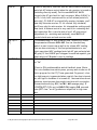
Filter Settings:
Main RX:
2.7
2.1
400 and 200
Sub RX:
2.7
2.1
400
Use of the filters:
Normal operation in CW:
2.1
Listening on 500 Hz BW or more
No need for other filter if band is normal
Contest operation in CW:
400
(also used if heavy QRM)
Normal operation for SSB:
2.7
(this filter is much wider than 2.7 but that’s no
problem in normal band conditions)
Contest operation in SSB:
1.8
with DSP width of 2.1 KHz
To get this combination of DSP=2.1 and
crystal=1.8, one has to install the 1.8 filter as if
it were a 2.1, so it switches in at DSP=2.1. This
installation setup is most easily done using the
K3 utility. In practice, normalize, then use high
cut until the filter switches in. (Dave
Hachadorian, K6LL)
2.1
(needed when band is crowded)
For CW & Data Modes
200 Hz, 5-Pole filter recommended by Elecraft
Diversity means one receiver (main) in one ear and the other receiver (sub) in the other ear.
Both sub and main filters have the same offsets in diversity mode.
C:\My Documents\Ham\Equipment\Elecraft\Elecraft K3 General Notes.doc
Page 54 of 112
For general use, I use the 2.7kHz filter for data modes and, of course, for voice modes. I
occasionally use the .500kHz filter on DATA. Usually only during contests and crowded
conditions. (Joel B. Black)
80m
80m
40m
40m
20m
20m
DATA:
USB:
DATA:
USB:
DATA:
USB:
Lo
Lo
Lo
Lo
Lo
Lo
=
=
=
=
=
=
0.15;
0.00;
0.85;
0.00;
0.15;
0.00;
Hi
Hi
Hi
Hi
Hi
Hi
=
=
=
=
=
=
2.85
3.00
3.55
3.00
2.85
3.00
To reset your filter settings to a normal default value, hold the Shift/Lo knob until you see
the word "NOR" in the lower display. This is the easiest way to return to solid default values.
Those values will be different depending on the mode you are in. There is one set for CW and
another for SSB. If you are in a data mode I think you will get the CW settings.
Use the 200 Hz when the going is tough in both CW and Data modes.
FL1
13 kHz
(FM)
FL2
2.7 or 2.8 kHz
(SSB and casual CW/Data)
FL3
1.8 or 1.5 kHz
(Narrow SSB & wide CW/DATA)
FL4
or
400 or 500 Hz
700 kHz
(Normal CW/DATA)
(Casual/normal CW/DATA)
FL5
Or
200-350 Hz
(CW/DATA in heavy QRM)
350 Hz
(Optimum 45.45 RTTY)
C:\My Documents\Ham\Equipment\Elecraft\Elecraft K3 General Notes.doc
Page 55 of 112
According to Elecraft (Wayne, N6KR) while matched filters are optimal for matching
receiver performance, they're not strictly necessary if you're only doing non-diversity
receive. The K3 will select an appropriate filter bandwidth for each receiver independently.
He further says, if you want to do diversity receive, you'll need filters with matched offsets.
Our 8-pole filters all have offsets of 0.00, but can also do this with 5-pole filters as long as
the offsets are matched for a given crystal filter bandwidth. At the time you order the
filters, you can request matched sets
C:\My Documents\Ham\Equipment\Elecraft\Elecraft K3 General Notes.doc
Page 56 of 112
K3 Crystal Filter Setup:
The following text is copied from an e-mail written by Wayne, N6KR on February 13, 2009.
Taken from Offset (FLx FRQ)
---------------There are many considerations that go into the positioning of the K3's crystal filters with
respect to the I.F. center frequency. We shift them upward if the filter is too wide to be
centered at Fc/2 + 200 Hz, thus preserving the lower edge of the filter around 200 Hz. This
usually happens only in CW mode, typically with lower sidetone pitches. The result is
optimization for opposite-sideband rejection. You can argue for a different approach, but the
K3's success in CW DXing and contesting suggests that this approach is just as valid as any
other.
I don't recommend trying to fool the firmware by adjusting the crystal filter offsets; I'd
use the marked values. Changing them is likely to cause unwanted side-effects, since the
filter passband is inverted for complimentary modes (CW/CW REV, LSB/USB, DATA/DATAREV). The exception to this rule is when fine-tuning the offsets of 5-pole filters on the main
and sub-receivers in order to provide best performance in diversity mode. These adjustments
will rarely be larger than +/- 20 Hz anyway.
Bandwidth (FLx BW)
-----------------It's OK (but not necessary) to fudge the bandwidth of specific filters (FLx BW). For
example, INRAD's 8-pole "400 Hz" filter can be declared as 0.4, 0.45, or 0.5 kHz, depending
on where you want this filter to be kicked in as WIDTH is rotated. The audible effect is
subtle. Ed Muns, W0YK, has described this technique in detail elsewhere.
Gain (FLx GN)
------------Regarding filter loss compensation: I recommend simply sticking with what's on page 46 of
the owner's manual (1 to 2 dB compensation for 400-500 Hz filters, 3 to 4 dB compensation
for 200-250 Hz filters, and 0 for all others) unless you have a very specialized application
and lots of time on your hands.
There are three reasons for this. (1) The *perceived* loss of a crystal filter is a function of
both actual loss and S/N ratio. If a narrower filter has a little more loss, you may not notice
C:\My Documents\Ham\Equipment\Elecraft\Elecraft K3 General Notes.doc
Page 57 of 112
it. (2) Most signals are flattened slightly by AGC anyway. (3) Adding a lot of gain to filters
can again cause side-effects, such as interaction with RX EQ settings and variations in gain
between main and sub if the filter complements are different (e.g., during diversity use).
In fact we recently issued new guidelines for factory-assembled K3s: all crystal filters' FLx
GN numbers will be to 0 except for 400-500 Hz (1 dB) and 200-250 Hz (2 dB). Customers
are free to optimize these further, of course -- but most won't need to.
The K3 firmware does not allow the selection of any filter other than the 2.7 (2.8) kHz filter
for CW transmit. The menu does not prohibit setting it to any filter but it will not transmit
and will present you with a TXF error.
C:\My Documents\Ham\Equipment\Elecraft\Elecraft K3 General Notes.doc
Page 58 of 112
Roofing Filters:
There are recommendations in the K3 Owner's manual (see "Crystal Filter Setup", indexed,
on page 46) :
Use VFO A to set the gain in dB. In general, you'll want to add 1-2 dB for 400-500 Hz
filters, and 3-4 dB for 200-250 Hz filters.
and there is a table (with essentially the same guidance) in K3 Utility Help for the Filter
Configuration page. I've lost the table formatting in cut/paste from Help, but here's the
information:
Narrow crystal filters tend to have more passband loss than wide filters.
You can compensate for this effect by specifying an amount of added gain to use for each
filter in receive mode. Enter the desired gain "boost", in decibels, for each filter. You may
specify a value between 0 and 8 dB.
Elecraft recommends using the initial loss compensation values below. You may wish to
further adjust the values for your particular filters.
Part Number Bandwidth Gain
KFL3A-200 0.20 kHz 3-4 dB
KFL3A-250 0.25 kHz 3-4 dB
KFL3A-400 0.40 kHz 1-2 dB
KFL3A-500 0.50 kHz 1-2 dB
KFL3A-1.0K 1.00 kHz 0 dB
KFL3A-1.8K 1.80 kHz 0 dB
KFL3A-2.1K 2.10 kHz 0 dB
KFL3A-2.7K 2.70 kHz 0 dB
KFL3A-2.8K 2.80 kHz 0 dB
KFL3A-6K 6.00 kHz 0 dB
KFL3B-FM 13.00 kHz 0 dB
My radio
My radio
C:\My Documents\Ham\Equipment\Elecraft\Elecraft K3 General Notes.doc
Page 59 of 112
Drew (AF2Z) makes the following comments:
If I use a 50uv signal generator to set the filter gains for equal readings on my K3's AFV
meter I arrive at the following compensations:
2.70 KHz = 0db
500 Hz = 4 db
250 Hz = 8 db
This is way more aggressive than the suggested amounts but these figures do sound equalized
to my ears for real signal conditions. The factory settings are noticeably weak. Maybe my
particular filters are just not up to par.
Rich VE3KI states the following: "I assume you are talking about CW operating; for RTTY, I
believe the 200 Hz filter is a bit too narrow and degrades copy too much (for RTTY
contesting, the so-called "250 Hz" roofing filter, set to switch in at 350 Hz, seems just
about right to me).
You need to keep in mind the difference between the impact of a narrower roofing filter vs.
the impact of just dialing in a narrower DSP filter bandwidth. In some (but not all) situations,
it is the DSP bandwidth setting that matters, more so than the choice of roofing filters.
Regardless of what roofing filters you have, the K3's IF bandpass is quasi-continuously
variable all the way down to 50 Hz. If the QRM is only to one side of you, the Shift control
also gives you an added weapon to attenuate an unwanted signal even without narrowing down
the bandwidth. The roofing filters do not change this. What the roofing filters give you is
the ability to keep unwanted signals out of the IF chain where they can create IMD products
and affect AGC gain even when you can't hear them directly because of the DSP filtering. If
you rarely operate in crowded conditions such as a major contest, a very narrow roofing filter
might not do much for you.
In an ideal world, my recommendation would be to first determine what DSP filter
bandwidths you prefer to operate with, and after having done that, buy and install the next
wider roofing filter corresponding to each of your preferred (i.e. most-frequently-used) DSP
filter bandwidths.
Personally, I find a 200 Hz filter setting too narrow for routine CW searching and pouncing,
but maybe I'm just turning the dial too rapidly. With a very narrow filter setting, I tend to
tune right past stations without hearing them, especially in a contest or DXing situation
where transmissions are very short. If you do all of your S&P operating using the DX cluster
or a Skimmer to find stations, this might be less of a concern for you.
C:\My Documents\Ham\Equipment\Elecraft\Elecraft K3 General Notes.doc
Page 60 of 112
If you call CQ a lot, you might find that a significant number of callers come back to you
farther away from your frequency than 100 Hz. With a 200 Hz filter setting, these callers
would be outside your filter bandpass and you wouldn't be aware of them. There may be
times when this is exactly what you want, to thin out the crowd of callers, but I believe that
often you may find that a very narrow filter reduces your chances of hearing a reply to your
CQ, especially if you don't often attract large pileups.
Another way of looking at this is to consider how closely together in frequency stations tend
to operate. Even in a major CW contest, a separation of 250 Hz between neighbouring signals
seems not unusual to me. That 250 Hz separation corresponds to a 500 Hz filter bandwidth,
i.e. a 400 Hz roofing filter would significantly knock down the neighbouring signals on either
side of you. Of course, this ideal separation example doesn't happen all the time, and there
are times when even the DSP shift and width controls do not suffice and a narrower roofing
filter is what you would need to copy the desired signal. The question is, does this happen
often enough that a narrower roofing filter is justified for you? The answer to this question
will be different for different operating styles and situations.
The way I operate in CW, a 400 Hz roofing filter would be much more useful to me than a
200 Hz filter. It would be nice to have both, but if it's a matter of choosing one or the
other, for me the choice would clearly be the 400 Hz filter. YMMV."
C:\My Documents\Ham\Equipment\Elecraft\Elecraft K3 General Notes.doc
Page 61 of 112
QSK:
QSK use requires that both the VOX and the QSK indicators be activated. If QSK is visible
on the K3's display but VOX is not, QSK will not work. Hold the left end of the band switch
for VOX and the right end for QSK.
C:\My Documents\Ham\Equipment\Elecraft\Elecraft K3 General Notes.doc
Page 62 of 112
Elecraft K3 Front Panel Controls: Physical Location vs. Functions:
Wayne Burdick, N6KR; Revised 2-4-2009
Front Panel
Left Side Controls (left of LCD display bezel); "Primary Controls"
Note: The first two switches in this column are "rocker" switches,
with each end having different functions.
Column 1 (leftmost controls on panel)
Switch 1, left end: TAP = BAND DN; HOLD = VOX on/off
Switch 1, right end: TAP = BAND UP; HOLD = QSK on/off
Switch 2, left end: TAP = MODE DN; HOLD = ALT mode select
Switch 2, right end: TAP = MODE UP; HOLD = TX TEST on/off
Switch 3: POWER on/off
[TX and Delta F LEDS]
[PHONES JACK]
[MIC JACK]
Column 2
Switch 1: TAP = MAIN MENU; HOLD = CONFIG MENU
Switch 2: TAP = XMIT; HOLD = TUNE
Switch 3: TAP = RX ANT on/off; HOLD = sub ANT switch (MAIN/AUX)
Knob 1: Smaller knob = MAIN AF GAIN; Larger knob = SUB AF GAIN
Knob 2: Smaller knob = MAIN RF GAIN; Larger knob = SUB RF GAIN
Column 3
Switch 1: TAP = DISP (VFO B alt. displays on/off); HOLD = METER (TX bargraph)
Switch 2: TAP = ATU TUNE; HOLD = ATU normal/bypassed
Switch 3: TAP = ANT1/2; HOLD = Assign name to antenna (complex operation)
Center Controls (under LCD display bezel)
Note: Columns 1 and 2 contain two knobs each; they are the
"Multifunction Controls". Functionally, they are grouped left/right:
col 1/knob 1 and col 2/knob 1 are the DSP filter passband controls, and
col 1/knob 2 and col 2/knob 2 are control transmit functions. All
four knobs are left of the VFO A knob.
Column 1
Knob 1: SHIFT or LO-CUT; TAP = SHIFT/LO select; HOLD = NORMalize filter
Knob 2: SPEED or MIC GAIN; TAP = SPEED/MIC select; HOLD = DELAY (QSK/VOX)
Column 2
Knob 1: HI-CUT or WIDTH; TAP = HI/WIDTH select; HOLD = PRESET I/II select
Knob 2: "CMP/PWR/MON"; TAP = "CMP/PWR/MON" select; HOLD = MONITOR (sidetone
or voice)
C:\My Documents\Ham\Equipment\Elecraft\Elecraft K3 General Notes.doc
Page 63 of 112
[VFO A knob]
Column 3 (right of VFO A knob)
Switch 1: TAP = FREQ ENTRY; HOLD = SCAN
Switch 2: TAP = FINE on/off (1 Hz); HOLD = COARSE
Switch 3: TAP = RATE (10/50 Hz); HOLD = VFO LOCK
Switch 4: TAP = SUB on/off; HOLD = VFO LINK/UNLINK; LONG HOLD = DIVERSITY
Right Side Controls (right of LCD display bezel)
Columns 1/2/3: Numeric Keypad and Misc. Function Group
Note: The switches in these three columns form a 3x4 keypad for
use with FREQ ENTRY, so the switches are listed by *row* (three each)
in the list below. Switch '.' is used as the decimal point following
MHz; switch '<' is used as an 'enter' key to accept the direct numeric
frequency input. Directly below this 3x4 switch array is the VFO B knob.
Row 2
Switch 4: TAP = PRE on/off; HOLD = ATTN on/off
Switch 5: TAP = AGC slow/fast; HOLD = AGC on/off
Switch 6: TAP = XFIL; HOLD = DUAL PB (dual-PB CW or dual-peak RTTY filter)
Row 3
Switch 7: TAP = NB on/off; HOLD = NB LEVEL (VFO A = DSP NB, VFO B = IF NB)
Switch 8: TAP = NR on/off; HOLD = NR ADJUST (use VFO B)
Switch 9: TAP = NOTCH; HOLD = MANUAL NOTCH (use VFO to set notch freq.)
Row 4
Switch .: TAP = SPOT (or autospot if CWT is ON); HOLD = PITCH
Switch 0: TAP = CWT on/off; HOLD = TEXT DEC
Switch <: TAP = AFX on/off (simulated stereo, etc.); HOLD = DATA MD
Columns 4/5: Memory, DVR, Message, and RIT/XIT Control Group
Note: The switches in this group form an irregular array,
treated differently in the list below. The first row of 2 switches
are for memory and DVR control. Below this is a group of four
switches arranged in a circle (M1-M2 on the top of the circle, and
M3-M4 on the bottom), with a fifth switch in the middle (REC).
These are used for instant message play (CW/DATA or with DVR). They
may also be used with the memory switches as per-band "quick memories".
Below the circular group is a group of 3 switches used for RIT/XIT
control, and below this, the RIT/XIT OFFSET control knob.
Row 1: Memory and DVR Controls (rightmost controls on panel)
Left switch: TAP = V>M; HOLD = AF RECORD (DVR)
Right switch: TAP = M>V; HOLD = AF PLAY (DVR)
Row 2 (circular switch array):
C:\My Documents\Ham\Equipment\Elecraft\Elecraft K3 General Notes.doc
Page 64 of 112
M1-M2 (top), M3-M4 (bottom): TAP M1-M4 = msg play; HOLD M1-M4 = msg repeat
Center switch: TAP = MSG RECORD (follow w/M1-M4); HOLD = msg bank 1/2 select
Row 3: RIT and XIT Controls
Left switch: TAP = RIT on/off; HOLD = programmable menu function PF1
Right switch: TAP = XIT on/off; HOLD = programmable menu function PF2
Bottom switch: TAP = RIT/XIT CLR (tap again to undo clear, if enabled)
Knob: RIT/XIT offset control
C:\My Documents\Ham\Equipment\Elecraft\Elecraft K3 General Notes.doc
Page 65 of 112
Audio / IF Filtering Information:
The following information written by Don Wilhelm (W3FPR):
The Hi-Cut and Lo-Cut do essentially the same thing as Width and Shift, but they make voice
signals easier to deal with.
If you have played with Width and Shift on the K3 or other transceivers, you will know that
anytime you change the width control, you have to also change the shift control to maintain
intelligibility for the received voice signal.
The main reason is that you must have some audio content in the 300 to 500 Hz range to
have intelligibility in the human speech range. So if you have your Width set at 2.7kHz and
the Shift set at 1500 Hz, you will be receiving 300 to 3000 Hz. Now move the width to
2.1kHz and the passband changes to 600 to 2700 Hz, and you have lost much of the low
frequency content of the signal - changing the Shift control to a lower frequency will recover
that 300 to 500 Hz segment of the audio spectrum that is essential to communications
fidelity.
OK, the Hi-Cut and LoCut controls work in a similar manner as the Width and Shift. HiCut
reduces the high frequency content in the received signal while not changing the low
frequency end. That is ideal for voice communications where the 300 to 500 Hz content
must be preserved for good intelligibility. Try an experiment - set LoCut at 300 Hz and
then tune in an SSB signal. Reduce HiCut until you can no longer understand the vocal
content. If my guess is correct, you will still be able to understand the voice content when
HiCut is at 1500 Hz (that is a width of 1200 Hz).
Now try the same thing using Width and Shift - it will likely be cumbersome to adjust both
the Shift and Width to accomplish the same 1200 Hz width while keeping the 300 to 500 Hz
content active with the shift control.
So the result is to use Width and Shift for CW where the center frequency is well defined,
but on SSB (or other voice modes) the use of HiCut and LoCut makes things a lot easier - set
LoCut somewhere between 200 and 400 Hz and leave it there - HiCut can be reduced to
remove high audio frequency 'garbage' as desired. If you run into interfering signals on the
low audio frequency range, there is not much you can do about it without reducing signal
intelligibility (time to QSY).
C:\My Documents\Ham\Equipment\Elecraft\Elecraft K3 General Notes.doc
Page 66 of 112
APF Function:
This feature allows you to hear CW signals much better.
1. You need to set CONFIG:DUAL PB to APF.
2. Now select preset I, and turn APF ON by holding the DUAL PB switch.
3. Then switch to preset II and turn APF off again using the DUAL PB switch.
4. From then on you should be able to alternate between I and II and have APF turn on
and off.
5. You can also vary WIDTH for each preset. For example, for preset I, I set WIDTH to
200 Hz and APF on. For preset II I set WIDTH to 400 Hz with APF off.
6. Make sure the CW signal is centered in the passband at your selected pitch, before
engaging APF. For very weak signals, rely on your ear to match the pitch, rather than
using the K3 SPOT or CWT features.
7. Press the XFIL/DUAL PB key to enable the APF for more than one second.
8. After turning APF on, use the APF SHIFT (now 5 Hz resolution) and/or FINE tuning (1
Hz resolution) to peak the signal.
C:\My Documents\Ham\Equipment\Elecraft\Elecraft K3 General Notes.doc
Page 67 of 112
CWT Function:
1.
2.
3.
4.
5.
6.
CWT tunes to zero-beat your CW pitch
The capture range of CWT is about (+/-) 125 Hz
If the signal is noisy, CWT will not find it
Multiple signals within your passband will confuse CWT
CWT will adjust to the pitch set for your sidetone
In CW Mode, hold the “PITCH” button and adjust to a comfortable sound for you using
the VFO A knob
7. If CWT finds false zero beat at a very different pitch, narrow the filter (width
control) to a few hundred Hz and tune until you hear the signal with CWT “On” and
view the CWT moving dot display – then tap “SPOT”
Reverse
1. The mode reverse switch is labeled “ALT”. It is activated by holding the left end of
the “Mode” switch. The switch labeled “REV” between the “A/B” and “A>B” is actually a
momentary contact version of “A/B”. If the “ALT” switch is not switching between
USB and LSB, you may have a hardware problem with the switch.
Split Operation
1. Tap the “A/B / SPLIT” button once to place VFO A and VFO B on the same frequency
2. Tap the “A>B / BSET” button twice to place VFO B in the same mode as VFO A with all
the same settings
3. Set VFO B to the desired frequency and press and Hold the “A>B / SPLIT” button
4. Hold the “A/B BSET” button to access VFO B
5. Hold the button labeled “REV” on the K3 to listen on your transmit frequency while in
Split mode. There is no tap vs. hold with this button, when held, it temporarily
reverses VFOs A and B.
If turning the main tuning knob changes the frequencies in both VFOs, your two VFOs are
linked. Hold the SUB button to unlink them.
To lock your receive frequency so that turning either tuning knob cannot change it, you
can use the LOCK button, provided the two VFOs are not linked. However (I am not sure
whether this qualifies as a bug or a feature), LINK appears to take precedence over
LOCK. That is, when the two VFOs are linked, turning the VFO A knob changes the VFO B
frequency even when the lock symbol is displayed beside VFO B. Personally I would have
C:\My Documents\Ham\Equipment\Elecraft\Elecraft K3 General Notes.doc
Page 68 of 112
expected the reverse (LOCK to take precedence over LINK).
The K3 has 11 "bands" that are cycled through with the up/down "Band" switch. Each
band permits reception on a range of frequencies and transmission on the ham band
located within each of these ranges. While this might be (probably is) published
someplace, I empirically determined the following:
Band 1:
Band 2:
Band 3:
Band 4:
Band 5:
Band 6:
Band 7:
Band 8:
Band 9:
Band 10:
Band 11:
0.490 --> 2.999 MHz
3.000 --> 4.799 MHz
4.800 --> 5.999 MHz
6.000 --> 8.999 MHz
9.000 --> 12.999 MHz
13.000 --> 16.999 MHz
17.000 --> 18.999 MHz
19.000 --> 22.999 MHz
23.000 --> 25.999 MHz
26.000 --> 30.000 MHz
44.000 --> 54.000 MHz
When you are on one of these bands and tune a frequency within the given range, it will
be remembered the next time you cycle to that band.
If you want to guarantee that you are on the given ham band, program the quick
memories and recall one of them. Using the M1-M4 memories you can then remember a
given mode and band segment. I use mine for CW, SSB, RTTY and PSK, each at the
"nominal" frequency for the mode.
C:\My Documents\Ham\Equipment\Elecraft\Elecraft K3 General Notes.doc
Page 69 of 112
Preamp:
Don (W3FPR) comment, “One thing I might point out up front is that the K3 has more gain
(sensitivity) than is usable in many situations. Do not turn on the preamp unless it is
necessary. If you can hear an increase in the "band noise" when an antenna is connected
(with the preamp off), then the preamp will do you no good other than increase the band
noise you have to listen to. If you have a lot of "band noise" even with the preamp off, then
turning on the attenuator for that band may help too.
Remember the "rule" -- if the band noise increases when the antenna is connected, you have
more than enough receiver sensitivity for that particular band and antenna - additional gain
will only result in hearing more noise on the band and will decrease the receiver dynamic
range (as well as subjecting your ears to a constant local noise level).”
C:\My Documents\Ham\Equipment\Elecraft\Elecraft K3 General Notes.doc
Page 70 of 112
VOX:
Delay
VOX "hold time" is set with the DELAY knob on the K3.
HOLD (press for ½ sec) the SPEED/MIC knob to activate this function. Delay is shown in
seconds on the LCD as you adjust it.
See VOICE MODE VOX SETUP in your Owner's manual for more information (Pg 29 in the
Rev D manual).
C:\My Documents\Ham\Equipment\Elecraft\Elecraft K3 General Notes.doc
Page 71 of 112
K3 Breakout Box:
Bud Governale provided a wiring diagram for a breakout box that he made to capture all the
possible needed connections that come from the K3 accessory connector. Using this box, one
can use two COM ports with RS232 cables; one for radio control and one for FSK RTTY
keying. The diagram is available as a .pdf file from my website: www.n3me.net/pdf/K3
Breakout Box wiring diagram.
I elected to use the LP_Bridge software, which creates virtual com ports.
C:\My Documents\Ham\Equipment\Elecraft\Elecraft K3 General Notes.doc
Page 72 of 112
Macros:
Rich - K1HTV wrote the following:
"After seeing the note about creating a macro to toggle between two power levels on the K3,
I thought I would try writing a macro for a triple toggle. With this macro the K3 power
output can be toggled between 10W, 50W and 100W using the PF2-HOLD key. If you prefer
to TAP instead of HOLD, use one of the M1-4 keys and change the SWH47 to the
appropriate "SWTnn" number. Refer to the K3 Macro tutorial.
This is being written not only for the K3 users who already know how to write macros, but for
those K3 users who have never done so and want to give it a try. So please excuse the extra
steps which must be performed that you already know how to do.
Assuming that you already have the K3 Utility installed on your computer, turn on your K3.
Start the K3 Utility and confirm that your K3 is communicating with your computer.
Click the "Test Communications" tab.
Click "Port Test Communications". If successful you will get a box indicating so.
Click the "Command Tester/K3 Macros" tab.
Click "Edit Macro"
Use the information below to populate the "Macro Label" boxes and the Macro Commands"
boxes for the macro number that you will be using. At K1HTV I used the K3's 5, 6 and 7
macros for the triple power toggle. If you use other ones, change the SWT29, SWT33 and
SWT27 to the appropriate numbers for the macro numbers you want to use. You can type in
the info below, but you will probably find it easier to simple cut and paste the commands (the
ones with the semicolons between) from this document into the K3 Utility macro boxes being
used.
Macro#
5
Label
10W
(10W) (Macro) (6) (PF2H) (Menu)
PC010;MN110;SWT29;SWH47;SWT14;
6
Label
50W
(50W) (Macro) (7)
(PF2H) (Menu)
PC050;MN110;SWT33;SWH47;SWT14;
Label
(100W) (Macro) (5)
(PF2H) (Menu)
7
100W
PC100;MN110;SWT27;SWH47;SWT14;
After you have filled in the "Macro Label" and :Macro Commands" boxes for Macro
5 (10W), Macro 6 (50W) and Macro 7 (100W) click on "Write Macros 1-8 to K3".
C:\My Documents\Ham\Equipment\Elecraft\Elecraft K3 General Notes.doc
Page 73 of 112
Next, at the K3:
Hold the MENU key.
Rotate the VFO-B dial until "MACRO" appears.
Tap the "5" on the keypad so the screen reads "MACRO 5".
Hold the PF2 key until "PF2 SET" appears.
Tap the MENU key.
Hold the MENU key again until MACRO appears.
Tap "6" on the keypad so the screen reads "MACRO 6".
Hold the PF2 key until "PF2 SET" appears.
Tap the MENU key.
Tap "7" on the keypad so the screen reads "MACRO 7".
Hold the PF2 key until "PF2 SET" appears.
Tap the MENU key.
Test by holding the PF2 key until either 10W, 50W or 100W appears briefly on the LCD
screen. It should toggle between the three power levels each time you HOLD the PF2 key.
*** NOTE***
When writing lines of multi-line toggling macros, make sure the number for the macro number
following the MN110; is the macro number for the following line or the toggle feature will not
work.
C:\My Documents\Ham\Equipment\Elecraft\Elecraft K3 General Notes.doc
Page 74 of 112
Rich (K1HTV) also created the following macros:
"... I use to set up my K3 for USB, CW, DATA-A and RTTY. Parameters that are set up
include mode, receiver bandwidth, audio input connector (Front Panel for microphone, rear
Line-In jack for DATA-A modes), Mic Gain and Compression level for SSB, CW Speed, VFO
lock for DATA-A modes like PSK31, JT65 and WSPR. You can add or change other
parameters in the macros for the various modes as you see fit.
After the following 4 macros are loaded in MACRO positions 1,2,3 & 4 and programmed into
the PF1 key, when you HOLD the PF1 key the K3 will toggle the K3 between the USB, CW,
DATA-A and RTTY modes.
# MacroLabel Macro Commands
1 USB-PF1
MD2;MN053;DN;DN;MG026;CP020;LK0;BW0250;MN110;SWT12;SWH45;SWT14;
2 CW-PF1 MD3;LK0;BW0040;KS025;MN110;SWT13;SWH45;SWT14;
3 DTA-PF1 MD6;DT0;MN053;UP;UP;BW0250;LK1;MN110;SWT24;SWH45;SWT14;
4 RTT-PF1 MD6;DT2;MN053;DN;DN;BW0050;LK0;MN110;SWT11;SWH45;SWT14;
The next 3 macros (5,6 & 7) use the PF2-HOLD key to toggle the K3 between three power
levels, 10, 50 & 100 Watts.
#
5
6
7
MacroLabel Macro Commands
10W-PF2 PC010;MN110;SWT29;SWH47;SWT14;
50W-PF2 PC050;MN110;SWT33;SWH47;SWT14;
100WPF2 PC100;MN110;SWT27;SWH47;SWT14;
For those that haven't yet programmed multiple macros into one of the PF1 or PF2 (HOLD) or
M1-8 (Tap or Hold) keys, the procedure is:
With the K3 powered on, open the K3 Utility.
Click on the "Port" tab then click "Test Communications".
If the results is successful K3 status, click OK.
Click on the "Command Tester/K3 Macro" tab.
Click on "Edit Macros" in the upper right corner.
You can cut the Macro Label and Macro Commands from above and paste them into the
correct boxes for each macro number.
When all the data has been entered:
Click on "Write Macros 1-8 to K3".
Click "Save" then close or minimize the K3 Utility.
C:\My Documents\Ham\Equipment\Elecraft\Elecraft K3 General Notes.doc
Page 75 of 112
Next, at the K3, to assign the macros to the PF1 HOLD key:
1) Hold the MENU key.
2) Rotate the VFO-B dial so it reads to "MACRO" on the lower half of the LCD screen and
FUNCTION" above it.
3) Tap the first macro # to be entered. The LCD will read "MACRO #"
4) HOLD the PF1 key until "PF1 SET" appears.
5) Tap the "Menu" key.
Go back to Step 1,using the next macro # in step 3, followed again by steps 4 & 5.
Keep repeating this until all macros have been stored in PF1.
Follow the same steps to assign the three "Power Level" macros 5,6 & 7 to the PF2-HOLD
key.
Test the mode change with repeatedly HOLD the PF1 key. Test power level with HOLDs of
the PF2 key.
C:\My Documents\Ham\Equipment\Elecraft\Elecraft K3 General Notes.doc
Page 76 of 112
Programmable Function Keys:
8.1.2 Programmable Function Keys with Macros
A sequence of commands that are assigned a programmable function key is
called a macro. The K3 Utility program is used to create and test
macros, and it has a number of macro examples in its help files. A full
explanation of the available commands is given in the Elecraft K3
Programmer's Reference manual and if you wish to make use of this
powerful feature, please download it from Elecraft website.
Here is how you can program PF1 to put the K3 into scanning. The
following commands are used in step 5 below:
SWT23;
Emulates a Switch Tap and 23 designates the M>V as the switch.
SWT11;
Emulates a Switch Tap and 11 designates the A/B switch.
SWH41;
Emulates a Switch Hold on the SCAN switch.
1.
Run the K3 Utility program.
2.
Click on Command Tester/K3 Macros tab.
3.
Click on the Edit Macros button.
4.
Let's assign Macro 3 to this function. In Macro Label 3 type in
the label SCAN.
5.
In the Macro Commands field, type in
SWT23;SWT11;SWH41;
6.
Click on Write Macros 1-8 to K3.
7.
Click on Save.
Before programming a function key on the K3, test the macro with the
Command Tester.
1.
2.
3.
4.
Click on the button labeled Scan.
If it doesn't perform properly, go back to the editor.
To program your K3 to hold PF1 for this macro,
Enter the CONFIG:MACRO x menu and tap 3 (if MACRO 3 is not
currently displayed).
Hold PF1 to program it to execute MACRO 3.
C:\My Documents\Ham\Equipment\Elecraft\Elecraft K3 General Notes.doc
Page 77 of 112
Remote Operation:
The following was provided by Olli (DH8BQA):
No problem at all and no dream anymore, the www.remoterig.com solution has everything you
mention already built-in, from VoIP to an own CW keyer also taking care of the internet
delays. Works like a charm (am using it with a IC-706 with the control head being 700 km
away from the rest of the radio and everything else) and no problems even with 80 ms
latency (read round trip time). Full control over the radio, exactly the same functionality as if
the control head was directly connected to the radio. “I” have made almost 1.500 QSOs with
that solution during the last 2 years (not that active due to QRL reasons).
Besides "modes" in their controllers for remoting the IC-706's or TS-480's heads over the
internet they also have profiles for using it with serial connections for radio control, i.e. CAT.
So a "self-made radio head" is no problem either, have tried that "half-way" myself already
with a small PIC display I built for my FT-817. So just create a front panel, send all button
presses as CAT commands to the remote radio, connect the microphone, key and speaker
directly to the remote rig controller and et voila, ready's your remote station with an
Elecraft remote head.
You can do that with a CAT software on the PC, too, i.e. Ham Radio Deluxe, but then you'll
loose the "feeling of spinning the dial" that's why I opted for the remote head solution with
the IC-706 although the radio is really not the best (and no comparison to my K3, of course.
I think this would be a real seller! Kenwood recently started producing and selling remote
heads for their TS-480's seperately besides "complete" transceivers as people are starting
to share their remote solutions so you need 3 or 4 heads for 3 or 4 guys to access the same
radio (not at once, of course).
K3iNetwork used with Skype will provide streaming audio to your iPhone, iPad or iPod Touch.
This is a no cost audio solution for those who are using the K3iNetwork. Review detailed
instructions at: www.ks7d.com/Skype.htm
This can be accomplished with non-Apple using a PC and MSN Messenger and a public ILS
server (or the old MSN Connect) or other desktop sharing utility like Adobe Connect to share
desktop control between two PCs. The shack PC needs to be left turned on and connected to
the K3 and running an application such as Ham Radio Deluxe. Just share desktops between
the two computers with control enabled and you can run any keyboard mode.
C:\My Documents\Ham\Equipment\Elecraft\Elecraft K3 General Notes.doc
Page 78 of 112
M. Foster (W0IH) Remote Setup:
"I do a limited amount of travel, but when away from home, I like to be able
to operate my K3 on the ham bands, and sometimes find that it gets a bit
complicated getting things setup to operate.
I’ve tried Ham Radio Deluxe and had mixed success getting connected up
remotely. The biggest problem is the need to know your IP address (you can
use DynDns or No-Ip). Plus, you still need to get the audio setup and
running. However, I’ve found what seems to be a simpler process and allows
for some added benefits.
*Remote Control Computer Software using Team Viewer*
To start with, I’m using TeamViewer which is free for non-commercial use.
http://www.teamview.com <http://www.teamview.com>
This is a computer remote control application that allows you to log into
another computer and view the desktop and control the computer. The added
benefits of TeamViewer is that it does not require you to know your base
station computer IP address, and also includes a VOIP (Voice Over IP) so
that you don’t need to start up a separate voice application like Skype.
When setting up, you just need to learn a few things, like when starting up
the VOIP, you need to enable the Voice-Over-IP and un-mute both the local
and remote microphones (there may be a setting to do this by default, but I
haven’t found it yet). I use an inexpensive computer headset with a
microphone and get very good audio reports.
There are more advantages to this where you can see your full remote desktop
applications, as I’ll point out later.
Incidentally, this will require that you keep your base station computer on
all the time. I turn off the monitor, it’s not needed. If you’re a bit
more ambitious, you may want to investigate using “Wake On Lan” for your
computer, but again, this is more complicated, but you could save this step
until later if you feel you need it.
C:\My Documents\Ham\Equipment\Elecraft\Elecraft K3 General Notes.doc
Page 79 of 112
*Power Up the AC and Rig Control Enable*
The next thing that you need to figure out is if you want to power your
radio on and off remotely. I happened to have a control that I can use to
turn on an AC power strip through a 15 amp AC relay. I modified a standard
AC strip by adding a cable from the AC black wire to go up to the relay and
then back down to the AC strip. Turning on the relay turns on the AC for my
12v power supply and my rotor control. This same control has a second
relay that allows making a connection to the ACC2 connector on the K3 to
remote power up the rig by pulling Pin 8 to Pin 5 (Gnd) for a short period
of time to turn on the K3. Reference page 18 of the K3 manual for this. To
power it off, you need to send a serial command to the rig from your K3
control software.
There are other options to allow relay control through the computer. Simply
do an on-line search for “usb relay” and you’ll come up with a number of
options, for as low as $30. You should be able to work with a 10 amp, 120
volt relay to power your rig and a few light peripherals.
The application that I wrote for the AC power strip also has a timeout, so
that if I lose the connection, it will automatically turn off the rig after
some period of time.
You might also consider another relay that would trigger the PTT line and
force a 5 to 10 minute timeout in case you lose the internet connection.
*Remote K3 Control using NO5W software:*
The K3 will of course need to be connected to the computer through the
serial port. The connection that you used for updating your K3 firmware is
the normal connection that is used for firmware updates.
As I mentioned before, you can use Ham Radio Deluxe, however, I found that
the CQX Client software available at http://www.no5w.com
<http://www.no5w.com> to be easier to learn and use. The software
package free and is intended for mobile contest logging (and seems very
nicely suited for this task, interfacing with a GPS) but the thing that I
like so well, is that once you connect up to your K3, there is a functional
K3 application (by clicking “More” button in the upper center of the
application) that allows you to control the K3 in a way that is very user
friendly. We’re lucky that Chuck is such an avid K3 fan!
C:\My Documents\Ham\Equipment\Elecraft\Elecraft K3 General Notes.doc
Page 80 of 112
For some examples: http://www.no5w.com/CQxK3RemoteKit.html
<http://www.no5w.com/CQxK3RemoteKit.html>
Quick Start Reference:
http://www.no5w.com/Documents/QuickStartForK3Testing.pdf
<http://www.no5w.com/Documents/QuickStartForK3Testing.pdf>
Basically, it has an operational picture of the K3 with the controls
activated so that each one works with the K3 using the same “tap” and “hold”
features that you’re used to, including the Power switch.
For remote operation, to turn the rig on, you pulse a set of contacts on
the K3 ACC2 connector and the rig powers up. To turn it off, you press the
“Power” button on the K3 application.
Frequency control is pretty simple. The normal control uses the Up/Dn keys
in conjunction with the resolution radio buttons just below the tuning knob.
There’s an added feature using the PgUp/PgDn keys to move 5 kHz for each
press.
There are a few minor things that you will need to learn, such as to adjust
the bandwidth, you can use the “Small” K3 Control Subset. I would suggest
that you play with the controls and get used to them before operating remote
from your vacation home. There are some very clever controls that allow
you to change a lot of the K3 settings with the various controls that are
built in.
I’ve been in contact with Chuck on his CQx application. He mentioned that
if there is enough interest, he could pull the K3 application out from the
logging software and make it available as a stand alone app. If you are
interested, just send a note to [email protected] and let him know you are
interested.
*Operation with Other Features*
Using TeamViewer, I found that there were some other added advantages in
that any application that you run on your base computer, can be viewed
through the remote station.
I have a rotator control that can be adjusted through a serial port. Using
the software for this (an option in Ham Radio Deluxe) I can turn my rotator
C:\My Documents\Ham\Equipment\Elecraft\Elecraft K3 General Notes.doc
Page 81 of 112
to any direction. The rotor controller is plugged into the same AC power
strip so it is powered up with the rig supply. Another somewhat simpler
application is LpRotor available at
http://www.telepostinc.com/ <http://www.telepostinc.com/>
“Downloads” along the left hand column.
Look for the
I have a P3 that I use with the K3, and I seem to be spoiled using it. It’s
a great addition to any station. Using a webcam, I point it at the P3 to
view the display before I leave. I open an application locally on the base
station so when I log in, it allows me to see the band display on the P3
visually to tune to any signal that I can see. I still want to try watching
both my P3 and K3 at the same time to see if I have enough resolution to
view both. This would allow me to verify all of my settings and feel a bit
more comfortable with everything.
Both of these applications run locally on the control computer. You simply
view and control them from the remote desktop.
*Other Modes:*
Sorry, but I’m not much of a CW operator these days, so that wasn’t a target
requirement for me. I haven’t tried it yet, but Ham Radio Deluxe also has
DM780 that supports CW through the keyboard, as well as other modes.
Another possibility that I found was CwType at
http://www.dxsoft.com/en/products/cwtype/
<http://www.dxsoft.com/en/products/cwtype/>
*Conclusion:*
I’ve found this every easy to use, and to be honest, I’m still learning.
One thing that I have yet to overcome is how to switch between my 3 antenna
connections, but solving these issues is part of the fun."
C:\My Documents\Ham\Equipment\Elecraft\Elecraft K3 General Notes.doc
Page 82 of 112
N3ME Elecraft K3 Menu Settings:
There are two groups of menu type functions: MAIN and CONFIG.
Tap the MENU/CONFIG button to access the MAIN menu; hold the MENU/CONFIG button
to access the
CONFIG menu.
Use the VFO A dial to select MAIN or CONFIG options.
Use the VBO B dial to set the option as desired.
Tap the DISP/METER button for information about the current setting displayed on the
front panel of the K3. For most entries, the default parameter value is shown in parentheses
at the start of the help text.
C:\My Documents\Ham\Equipment\Elecraft\Elecraft K3 General Notes.doc
Page 83 of 112
MAIN Menu entries:
Entry
Default
Description
ANTIVOX
000
ANTIVOX prevents the VOX (voice operated transmission)
circuit from being activated by the speaker output or room noise
from entering the microphone.
Increase the default setting to the level where the ambient
noise level will not key the microphone.
AFX MD
Bin
ALARM
OFF
LCD ADJ
8
LCD BRT
3
LED BRT
4
MIC SEL
rP.L
If you wish to use VOX, you need to set “VOX GN” and
“ANTIVOX” levels to what works best for the operator.
Audio Effects.
Delay 1-5 (quasi-stereo); BIN (L/R phase shift)
With “Bin” selected VFO A will be heard in left ear and VFO B
will be heard in right ear
The “AFX” button on the K3 front panel will turn “Sub” on / off
Alarm/auto-power-on time
Tap [1] to turn alarm on/off
Tap [2] to set HH
Tap [3] to set MM
LCD viewing angle and contrast.
Use higher settings, if the radio is used at or above eye level. If
adjusted incorrectly, bar graphs will be too light or too dark
during CW keying
LCD backlight brightness.
Use DAY in bright sunlight and 2 to 8 for indoor lighting.
LED brightness (relative to LCD backlight brightness)
Exception: if “LCD BRT” is set to DAY, LEDs are set to their
maximum brightness.
Microphone/line audio source, mic gain range and mic bias.
Source selections are:
FP.L for front panel 8-pin MIC jack
RP for rear panel 3.5 mm MIC jack
With K3 in DATA Mode use LINE IN for rear panel LINE IN
jack (monoaural)
Tap [1] to toggle between .Low and .High MIC gain range
Tap [2] to turn mic BIAS on/off (turn on for electret mics)
C:\My Documents\Ham\Equipment\Elecraft\Elecraft K3 General Notes.doc
Page 84 of 112
MIC+LIN
ON
For SSB Mode, set to ON, and “MIC SEL” is set for FP or RP, the
MIC or Line Input can be used for transmit audio.
For DATA Mode, set “MIC SEL” to LINE which will override the
“MIC+LIN” menu entry and its parameter becomes “N-A”.
MSG RPT
6
RPT OFS
0600
RX EQ 1
-----
When “MIC+LIN” is in effect, rotating the “MIC” control displays
MIC gain. You must set “MIC SEL” to LINE temporarily in order
to adjust the LINE IN gain.
Sets interval (in seconds) between message repeats (0 – 255).
To repeat a message, hold [M1] – [M4].
A 6 to 10 second interval is suggested for casual CQing.
Shorter intervals may be needed during contests.
A longer interval is suggested for periodic CW beacons.
Set transmit offset in kHz for repeater operations.
Adjustable from 0 to 5000 kHz.
Store per band and per memory.
Use “ALT” to select a +/- offset or simplex operation.
Receiver audio graphic equalizer
VFO A is used as an 8 band bar graph, where each character
displays the boost or cut (-16 dB to +16 dB in 1 dB increments)
for a given AF band. The 8 bands are 0.05, 0.1, 0.2, 0.4, 0.8, 1.6,
2.4 and 3.2 kHz.
TX EQ
-----
Tap [1] – [8] to select an AF band.
VFO A selects boost/cut.
Tap [CLR] to reset all bands to +0 dB.
Transmit audio graphic equalizer (voice modes only)
TX*EQ
Functions the same as the RX EQ and can be adjusted while in
transmit mode.
VOX GN
“TX*EQ” indicates “TX ESSB” is in effect
Adjusts the VOX sensitivity to match your microphone and voice
050
C:\My Documents\Ham\Equipment\Elecraft\Elecraft K3 General Notes.doc
Page 85 of 112
CONFIG Menu Entries:
Menu entries that include [T] are tech mode entries. These are only visible if
“CONFIG:TECH MD” is set to “ON”.
It is recommended that you set "CONFIG:TECH MD" to "OFF" after modifying any settings.
Entries described as “Advanced” or “Troubleshooting” should only be changed with caution.
Tap [DISP] to view the default value, which appears in parentheses at the start of the help
text.
Entries marked [SUB] have two settings: one for the main receiver and one for the sub
receiver. If a sub receiver is installed, the menu entries will change to identify which
receiver is being set up by showing RF (main receiver) or SUB (sub receiver) at the left end
of the parameter display. When in the SUB mode, the [SUB] icon will flash.
Prior to adjusting sub receiver menu parameters, turn the sub receiver on by tapping [SUB].
Turn “SUB AF” gain up and main “AF” gain down.
Even if the sub receiver is turned on, when you first enter the menu, RF will be in effect and
the [SUB] icon will be turned off. Tap [SUB] to switch to the sub receiver parameter as
required.
C:\My Documents\Ham\Equipment\Elecraft\Elecraft K3 General Notes.doc
Page 86 of 112
2 TONE [T]
OFF
ADC REF [T]
5.01
AF GAIN
AF LIM
HI
nor 030
AFSK TX
FIL On
AFV TIM [T]
1000
AGC DCY
Soft
(Troubleshooting) Enables built-in 2-tone generator for SSB
transmit tests. The internal 2-tone generator only works if
LSB or USB mode is selected. After setting the tone ON, exit
the menu and tap “XMIT”. You can use [MIC] to adjust the
amplitude of one of the tones; the other’s amplitude is fixed.
Allows calibration of the voltage reference used by the K3 to
measure and display certain values, such as the rig’s supply
voltage. (Optional.) First, disconnect anything attached to the
ACC jack. Next, locate the ADC REF menu entry. It will initially
show 5.00 volts as the reference voltage. Using a DMM set to
DC volts, measure the actual voltage at pin 2 of the ACC jack.
This must be done while the ADC REF parameter is being
displayed. (Note: The (-) probe of the DMM should go to the
K3’s chassis ground, e.g. at the GROUND lug.) Finally, use VFO
A to set the ADC REF menu parameter to what you measured at
pin 2.
Sets the AF gain range. Available selections are HI or LO
(Advanced) Adjustable AF output limiter for use when “AGC” is
turned off. This can protect your ears if a large signal appears.
Signals or noise above the threshold will sound highly distorted
due to the limiting action, reminding you to back down the “AF”
or “RF” gain. Typical settings for those who often turn “AGC”
off are 17 to 23. Available selections are 001 to 030
If set to FIL ON, A 400 Hz transmit audio filter is added (via
DSP) in order to maximize transmit signal to noise ratio. This
may be useful in high noise computer environments. This
applies only to AFSK-A mode (RTTY).
(Advanced) Integration time for AFV and dBV displays in ms.
See also VFO B alternate display information.
Available selections are Normal and Soft
AGC decay characteristic; applies to both fast and slow AGC.
NOR selects traditional linear decay. The SOFT setting can
reduce IMD caused by traditional AGC, and is especially useful
in “pileup” conditions, in some cases making it unnecessary to
turn AGC off. Also see AGC HLD, below, which can reduce AGC
IMD even further.
C:\My Documents\Ham\Equipment\Elecraft\Elecraft K3 General Notes.doc
Page 87 of 112
AGC HLD
0.20
12/2011
0.05
Original
AGC PLS [T]
AGC SLP [T]
nor
012
AGC THR [T]
005
AGC-F [T]
100
AGC-S [T]
020
AUTOINF
[T]
nor
BAT MIN
11.0
BND MAP
{band} In
CW IAMB
A
CW PADL
tip=dot
Available selections are 0.01 up
SLOW AGC “hold” time. Specifies the number of seconds that
the SLOW AGC level is held after the signal drops. This can be
used to reduce IMD caused by traditional AGC, and is especially
useful in “pileup” conditions, in some cases making it
unnecessary to turn AGC off. Also see AGC DCY, above.
(Advanced) NOR enables AGC noise pulse rejection.
(Advanced) Higher values result in “flatter” AGC (making
signals at all amplitudes closer in AF output level).
(Advanced) Sets AGC onset point; a higher number moves the
onset up.
(Advanced) Sets slow AGC decay rate; a higher number means
faster decay.
(Advanced) Sets slow AGC decay rate; a higher number means
faster decay.
(Advanced) If set to AUTO 1, the K3 will send band data on its
RS232 port for use with devices such as the SteppIR™ antenna
on every band change. (Note: This setting may not be
compatible with PC software applications that use the “AI”
remote control command.)
Low-battery warning threshold; 11.0 recommended. (This
refers to a battery used as the K3’s DC power supply, not to
the 3-V backup battery for the real-time clock.) If the voltage
drops below this level, the operator will be alerted with a
BAT LOW message. The menu parameter flashes if this occurs
within the menu, so the level can be easily tested.
Allows you to remove one or more bands from the BAND
rotation. Use BAND up/down to select bands, then set them to
In or Out using VFO A. (Works with transverter bands, too.)
You can still get to mapped-out bands using memory recall,
direct frequency entry, or computer-control commands.
Iambic Keying Mode (A or B)
Mode B is more efficient for operators who use “squeeze”
keying (pressing both paddles at once)
Specifies whether left keyer paddle is Dot or Dash.
C:\My Documents\Ham\Equipment\Elecraft\Elecraft K3 General Notes.doc
Page 88 of 112
CW QRQ
CW WGHT
OFF
1.15
Note:
Using
AUTO
OFF
In order
to stop K3
from
keying
when
computer
starts up
DATE
MM.DD.YY
DATE MD
US
DDS FRQ [T] 3.581.802
CW keying weight
Adjusts element/space timing ratio for the internal keyer
Tap [1] to select SSB + CW (allows CW keying in SSB modes) or
SSB – CW (no CW keying in SSB modes (this is the default)
Tap [2] to specify how the ‘@’ character should behave when
embedded in remote control KY (“key”) packets.
Select “@” = STOP to allow the ‘@’ character to terminate KY –
packet transmission (this is the default)
Select ‘@’ = AC to have ‘@’ translated into its Morse equivalent
Tap [3] to select OLD or NEW QSK (default). NEW QSK
reduces keying artifacts in the presence of QRN or QRM. OLD
mutes/unmutes slightly faster.
Tap 4 to select VOX NOR or AUTO OFF for CW VOX (hit-thekey CW). VOX NOR is the default, making the CW VOX setting
permanent. The AUTO OFF setting turns CW VOX off on
power-up. This is useful with some station setups where a
computer might accidentally key the K3 at power-up.
The real time clock date, shown in the format selected by
CONFIG:DATE MD (MM.DD.YY or DD.MM.YY).
Tap [1] / [2] / [3] to select month / day / year
Select US (MM>DD>YY) or EU (DD.MM.YY) date format
(Troubleshooting) Controls DDS tuning directly to check DDS
XFIL range for synthesizer troubleshooting purposes. Rotate
VFO A CCW and CW to find limits where L (lock) changes to U
(unlock). Correct DDS frequency is restored after exiting the
menu and rotating either VFO.
C:\My Documents\Ham\Equipment\Elecraft\Elecraft K3 General Notes.doc
Page 89 of 112
DIGOUT1
On
DUAL PB
EXT ALC [T]
APF
OFF t-4.0
DIGOUT1 is a general purpose open-drain output signal on the
ACC connector (pin 11). OFF = floating; ON = pull the line to
ground. DIGOUT1 is per band and also per antenna if the KAT3
ATU is installed. It can be used to turn an Elecraft PR6
preamp on when you switch to 6 meters, control a remote
antenna switch, etc. Max load current (ON) is 15 mA; max load
voltage (OFF) is 25 VDC.
Set to NOR to use
(Advanced) Set to ON only if using external ALC with a high
power amplifier. This may require modifications to your K3’s
RF and KIO3 modules.
When set ON, the K3’s external ALC threshold (-4.0 V by
default) can be varied.
When in AM or SSB Mode the following CONFIG items are available:
FL1 BW
[SUB]
rF 2.70
FL1 FRQ
[SUB]
rF -0.90
FL1 GN
[SUB]
rF 0 dB
FL1 ON
rF Yes
Crystal filters FL1-5 bandwidth in kHz, where x = 1 to 5.
Tap [1] – [5] to select a specific filter.
Tap [XFIL] (6) to select the next filter.
Tap [7] to turn IIR DSP filters on (IIR ON) or off (IRR OFF),
(default) for the 100 and 50 Hz bandwidths. IIR filters have
steeper skirts and slightly more ringing than the default FIR
filters.
Crystal filter FLx center freq as offset from nominal (8215.0
kHz. Use the offset value specified on the crystal filter’s label
or PC board. If an Elecraft 5-pole, 200 mHz filter were
labeled “-0.91”, adjust VFO A for -0.91
Crystal filter FLx loss compensation in dB. 0 dB recommended
for wide filters, 2 dB for 400 or 500 Hz filters, and 4 dB for
200 or 250 Hz filters
C:\My Documents\Ham\Equipment\Elecraft\Elecraft K3 General Notes.doc
Page 90 of 112
When in CW or DATA Mode the following CONFIG items are available:
FL3 BW
FL3 FRQ
FL3 GN
FL3 ON
rF 0.40
rF 0.00
rF 2 db
rF yes
When in FM Mode the following CONFIG items are available:
The FM filter, if installed, must be in FL1.
FL1 BW
FL1 FRQ
FL1 GN
FL1 ON
rF 2.70
rF -0.90
rF 0 db
rF no
FLTX {mode}
FL1
all modes
Use to specify which crystal filer to use during TX
{md} = CW/SSB/AM/FM
Choose filters with bandwidths as follows:
SSB 2.7 or 2.8 kHz (also applies to data)
CW 2.7 or 2.8 kHz
AM 6 kHz
FM 12 kHz or higher
Note: If you use a 2.7 kHz 5-pole filter for SSB transmit, you
can optionally fine-tune its FLx FRQ parameter to equalize
LSB/USB transmit characteristics. Monitor your signal on a
separate receiver, using headphones.
C:\My Documents\Ham\Equipment\Elecraft\Elecraft K3 General Notes.doc
Page 91 of 112
FM DEV
FM MODE
FP TEMP
5.0
ON
39-43 C
FSK POL
1
FW REVS
uC 04.60
d1 02.80
d2 02.80
FL 01.15
dr 01.03
KAT3
Auto
byp when
returned
from
Elecraft
(Advanced) FM deviation in kHz
If set to OFF, FM will be removed from the mode selections
Used to calibrate the front panel temperature sensor. This
must be calibrated, if you wish to use the REF xxC menu entry
to calibrate the optional 1 PPM TCXO. You must convert F to C
in order to enter the value. Degree C = (degree F – 32) * 0.555
0 = inverted DSK transmit data polarity
1 = normal data polarity
Rotate VFO A to see firmware revisions:
(uC) = MCU
(d1) = Main DSP
(d2) = Aux DSP
(only if KRX3 is installed)
FL = flash parameters
dr =
(only if KDVR3 controller is installed)
KAT3 Antenna Tuner mode
Normally set to BYP or AUTO (you can alternate using the ATU
switch. Modes L1-L8, C1-C8 and Ct are used to test KAT3
relays. Mode LCSET allows manual adjustment of L/C/net
settings. When in this MODE, tapping [ATU TUNE] shows the
L & C value; C is changed with VFO A. L is changed with VFO B.
and [ANT] toggles between Ca and Ct. Tapping [CLR] within
this menu entry clears the stored LC data for the current
band.
C:\My Documents\Ham\Equipment\Elecraft\Elecraft K3 General Notes.doc
Page 92 of 112
KBPF3
[SUB]
KDVR3
Not Inst
If KBPF3 is installed, set to NOR, exit menu, turn power off/on
nor
KIO3
KNB3
[SUB]
KPA3
nor
rf nor
KRC2
--
KRX3
Ant=bnc
KXV3
nor
If KDVR3 is installed, set to NOR, exit menu, turn power
off/on
Determines function of BAND0-3 outputs on ACC connector
(Troubleshooting) The K3 can’t be used without a KNB3; The
Not Inst setting is for troubleshooting only.
Set to PA nor if the 100 watt amp is installed.
Set to PAIO nor if the 100 watt amp is not installed.
Set to PA BYP to disable KPA3 if installed.
PA fan test settings:
PA FN1-FN4 or PAIO FN1-FN4 (if transition board is
installed, but not the KPA3 module, this setting can be used to
test the high power bypass relay).
Controls the KRC2 band decoder’s accessory output settings.
Shows ACC OFF or ACC1-3 if a KRC2 is detected and “—“ if
not.
To ensure compatibility with both old and new KRC2 firmware,
two different 6 meter band decodes are provided.
Tap [1] to select BAND6=B6 (addr=10) or BAND6=B10
(addr=9). Refer to the KRC2 manual for further details.
If the KRX3 option (sub receiver) is installed, set the
parameter to match your selected sub receiver AUX RF source:
ANT=ATU (the KAT3’s non-transmit antenna) or ANT=BNC
(the AUX RF BNC jack on the rear panel). Turn power off,
then back on.
If the KXV3 option is installed, set to NOR, exit menu and turn
power off/on. This option provides RX ANT IN/OUT jacks,
low-level transverter I/O (XVTR IN/OUT), and a buffered I.F.
output.
If the KXV3 is set to TEST, the K3 will use low power (0.10 to
1.50 mW) on all bands, including HF and transverter bands. RF
input/output is via the XVTR IN/OUT jacks in this case. Used
for troubleshooting. Note: To access the TEST setting, KXV3
must first be set to NOR, then K3 power off/on.
PA nor
C:\My Documents\Ham\Equipment\Elecraft\Elecraft K3 General Notes.doc
Page 93 of 112
LCD TST
LIN OUT
OFF
nor 010
Changing the parameter turns on all LCD segments.
Sets the LINE OUT level. LINE OUT connections go to
computer soundcard inputs. Settings above 10 may result in
overdrive of the soundcard or saturation of the KIO3’s
isolation transformers. Monitor signals using the computer to
avoid this.
Note: Normally, “LIN OUT” sets a fixed level receive only
output for main/sub (L/R), compatible with digital modes.
Tapping the [1] switches “LIN OUT” to = PHONES, where the
line outputs match headphone audio, audio level is controlled by
AF/SUB gain controls, and both RX and TX audio are available.
MACRO 1
MACRO 2
MACRO 3
MACRO 4
MACRO 5
MACRO 6
MACRO 7
MACRO 8
Function
Function
Function
Function
Function
Function
Function
Function
C:\My Documents\Ham\Equipment\Elecraft\Elecraft K3 General Notes.doc
Page 94 of 112
MEM 0—9
MIC BTN
L—MIX—R
NB SAVE
PA TEMP
PB CTRL
nor
Can also select “Band Sel”
If set to BAND SEL, frequency memories 0-9 (“quick memories”)
will act like band switches. Once this mode has been selected,
you can use V M to assign individual bands to keypad switches 09. For example, use [BAND] to get to 160 m, tap V M, then tap
#1 . From then on, tapping M V , then #1 , will take you to your
last-used frequency on 160 m, just as if you had used the
[BAND] switch. Up to 10 bands can be assigned to keypad
switches in this way, including transverter bands. The behavior
of memories 10-99 and the per-band quick memories ([M1]-[M4])
will be unchanged.
OFF
Set to ON if you use a microphone with UP/DOWN buttons
compatible with the K3’s front panel “MIC” jack. This is not
applicable to the Elecraft MH2 or MD2 microphones. “MIC”
FUNCTION button is not presently supported.
Tapping “UP” or “DOWN” once will move the VFO up or down one
step (based on the current tuning rate). Holding “UP” or “Down”
will move up or down continuously. If you see the frequency
moving up or down continuously, your microphone is not
compatible and “MIC BTN” must be set to OFF.
A b
VFO A = left spkr – VFO B = right spkr / Splits in both ears if
“SUB” button is “On”
No
Set to YES to save noise blanker on/off state per band. Noise
blanker levels, both DSP and I.F. are always saved per band
regardless of this setting.
33 C - 39 C If a KPA3 (100 watt PA module) is installed, this shows the KPA3
heatsink temperature and allows it to be adjusted. The
calibration procedure is explained in the manual.
If you’re operating at high power from a battery, and voltage is
dropping enough to cause an erroneous HI TEMP indication, tap
[1] to select R ONLY (receive only) temperature sensing, rather
than the default (T AND R).
Shift=.05
C:\My Documents\Ham\Equipment\Elecraft\Elecraft K3 General Notes.doc
Page 95 of 112
PTT-KEY
rts-dtr
set to
OFF-OFF
when
returned
from
Elecraft
PTT RLS
020
PWR SET
nor
REF CAL or
REF xxC
[T]
49.379.861
RFI DET
49.379.91
when
returned
from
Elecraft
nor
(Advanced) This allows the selection of RTS or DTR RS232
lines to activate PTT or key the K3, which I use for CW & PSK
software operation
Note: If the computer or other device asserts “RTS” or “DTR”
while you are in this menu entry, the K3 will switch to TEST
mode (zero power output) as a precaution. The TX icon will
flash as a reminder. To avoid this, make sure software
applications have flow control and/or keying options turned
“OFF” while you change the “PTT-KEY” selection.
(Advanced) This provides a delay between release of PTT and
dropping of the transmit carrier; intended for use with fast
turn around data protocols such as AMTOR and PacTOR. This
has no effect on CW, FSK D, or PSK D modes.
A value of 20 or higher may be needed to ensure accurate data
transmission with these protocols. If sync data or –S is in
effect (See SYNC DT), a lower value, typically 10 to 12, is
optimal. Also see AMTOR/PacTOR in the manual.
If set to NOR, the power level on each band follows the
present setting of the PWR control. If set to PER-BAND, the
power level is saved on each band. This is especially useful with
external amplifiers that have varying per band gain, as well as
with transverters.
Used to precisely calibrate the K3’s reference oscillator. VFO
A is used to set the reference oscillator frequency in Hz.
There should never be a need to set “REF CAL” outside a range
of 49377.000 to 49383.000. Typically it will end up much
closer to 49380.000.
Tap [1] to alternate between “REF CAL” (Method 1 or 2) and
“REF xxC” (Method 3).
Tap [2] or [3] to move the data entry point up or down. See
calibration procedure in the manual.
NOR enables detection of high RFI at the K3’s antenna in
receive mode (see HI RFI warning, Troubleshooting).
Set to OFF to disable the warning.
C:\My Documents\Ham\Equipment\Elecraft\Elecraft K3 General Notes.doc
Page 96 of 112
RIT CLR
undo on
RS232
set to
undo oFF
when
returned
from
Elecraft
38400 b
SER NUM
02462
When this parameter is set to “UNDO ON”, tapping RIT/XIT
CLR will alternate between 0.00 and the present RIT/XIT
offset, if any.
RS232 communications rate in bits per second (bps).
During firmware download (via the K3FW PC program), the baud
rate is set automatically to 38400 baud, but it is then restored
to the value selected in this menu entry.
K3’s serial number
C:\My Documents\Ham\Equipment\Elecraft\Elecraft K3 General Notes.doc
Page 97 of 112
SIG RMV [T]
nor
(Advanced) SPURIOUS SIGNAL REMOVAL: Fast-tuning
“birdies” can in some cases be eliminated using this menu entry.
We recommend that this be attempted only on birdies that can
be heard with an antenna connected. (In SSB mode, simply
leaving auto-notch on may be effective.)
STEPS: (1) Set up the receiver for a desired band, and select
the mode you’d normally use in the target band segment. Also
set the DSP passband controls to the settings you use most
often (e.g., NORMalized by holding NORM). (2) Locate a birdie
to be removed. A birdie is considered “fast-tuning” if a small
change in the SHIFT control (e.g. 50 Hz) moves the birdie
about 400 Hz or more (with a narrow filter selected, this small
shift may move it completely out of the passband). Such birdies
result from UHF harmonics of the VFO. If you test a birdie
using SHIFT, be sure to return SHIFT to its normal setting
before continuing, because the value of SHIFT affects the
birdie frequency. (3) Change the SIG RMV parameter to 0. This
will save necessary information about the birdie, including the
present VFO frequency, mode, filter, and SHIFT value. (4)
Try different parameter values, starting with -1 or 1, to see if
the birdie can be removed (shifted out of the audible
passband). Use the smallest effective value.
Important: If you change the parameter, exit the menu and see
if the birdie has disappeared. Each SIG RMV value applies to a
single 100-Hz VFO segment, e.g. from 28135.30 to 28135.39, so
you’ll have to tune slowly through that 100-Hz range using 10Hz steps to make sure the birdie has been completely removed.
You may hear a slight tuning artifact as you tune in and out of
the mapped-out segment. Note: In most cases, you’ll need to
apply SIG RMV to at least two adjacent 100-Hz VFO segments.
Also, if you use more than one filter bandwidth or SHIFT
setting in the present operating mode, you’ll probably need to
map out the birdie more than one time. If you change your CW
sidetone pitch, you may need to re-do the procedure.
To undo SIG RMV: If you tap CLR while you’re in the SIG RMV
menu entry entry, all birdie information for the present band
C:\My Documents\Ham\Equipment\Elecraft\Elecraft K3 General Notes.doc
Page 98 of 112
will be permanently deleted.
Limitations: SIG RMV applies only to CW/SSB/DATA modes,
and only to the main receiver (at present). Do not remove
birdies on transverter bands; instead, remove them on the I.F.
band. On each band from 160-6 m, up to 60 birdies can be
removed. But as mentioned above, each one may have to be
mapped out from adjacent VFO segments as well as for
different filter and SHIFT settings. So the number of birdies
that can be completely removed is around 5 to 20 per band.
C:\My Documents\Ham\Equipment\Elecraft\Elecraft K3 General Notes.doc
Page 99 of 112
SMTR OF
[SUB]
SMTR SC
[SUB]
SMTR PK
SMTR MD
OFF
nor
SPLT SV
No
SPKRS
2
SPKR+PH
Set to 1
when
returned
from
Elecraft
YES
SQ MAIN
00
YES = Speaker is On, even when headphones are plugged into
the PHONES jack.
This sets the main receiver squelch value (0 – 29).
00
If VFO A is rotated fully clockwise, the parameter changes to
=SUB POT. Squelch for both main and sub receivers will then
be controlled by the “SUB RF/SQL” knob, and both main and
sub RF gain will be controlled by the “MAIN RF/SQL” knob.
Sets the sub receiver squelch value (0 – 29).
SQ SUB
025
S-Meter offset. See calibration procedure.
016
S-Meter scale; S-9 = 50 uV, S-3 = 1 uV with Preamp = ON, and
AGC ON. See Calibration procedure.
Set to ON for peak reading S-meter.
(Advanced) S-meter mode: When set to NOR,
preamp/attenuator settings will affect the S-meter. (The
default values of SMTR OF and SMTR SC apply to NOR.) If set
to ABS, the S-meter reading will stay fairly constant with
different preamp/attenuator settings, but SMTR OF and
SMTR SC must be carefully realigned for both main and sub
receivers.
If set to YES, [SPLIT], [RIT], and [XIT] on/off states are
saved per band.
Set to 2 if using two external speakers. This enables binaural
effects in conjunction with the AFX switch, as well as stereo
dual-receive, if the sub receiver is installed.
If “SQ MAIN” is set to =SUB POT, then “SQ SUB” will also
change to =SUB POT. Squelch for the sub receiver will then
be controlled by the “SUB RF/SQL” knob, and both main and
sub RF gain will be controlled by the “MAIN RF/SQL” knob
C:\My Documents\Ham\Equipment\Elecraft\Elecraft K3 General Notes.doc
Page 100 of 112
SUB AF
nor
SW TEST
[T]
OFF
SW TONE
On
If set to BALANCE, then the SUB AF GAIN control becomes a
main/sub AF balance control when the sub receiver is turned on
(including diversity mode). In this case MAIN AF GAIN
controls the AF gain level for both receivers. When SUB AF is
at 12 o’ clock, both receivers will be at full volume (main left,
sub right). If SUB AF is rotated fully counter-clockwise, you’ll
hear only the main receiver. If it’s rotated fully clockwise,
you’ll hear only the sub receiver. At intermediate settings you’ll
hear both. A balance control is very useful for contesting and
split operation. But it can also save a lot of AF gain control
adjustment (i.e., matching main and sub), since MAIN AF
controls both main and sub receiver audio.
(Troubleshooting) To turn on switch test, rotate VFO A until
the parameter becomes SCN ADC. You can then hold any
switch to see its scan row as well as its column ADC reading.
You can also rotate any of the four potentiometers to see
their associated ADC readings (main/sub AF gain and main/sub
RF gain). If the SUB RF pot is mapped to main/sub squelch, you
must switch to FM mode to see its readings.
Sets audible control annunciation (tones or audio Morse code)
to “On”
If set to ON, enables audible switch feedback tones. (Note:
For voice feedback on switch press, you may wish to use our K3
Voice program for the PC.) Tones generated: In general, a lowto-high tone pair is generated when a switch function is turned
on, and high-to-low when it is turned off. Some switches do not
generate tones because they might interfere with received or
transmitted audio (e.g. REV, and M1 -M4 message play). If
CONFIG:RIT CLR is set to UNDO ON, tapping CLR a second
time (RIT clear “un-do”) produces a unique low-to-high tone
pair.
C:\My Documents\Ham\Equipment\Elecraft\Elecraft K3 General Notes.doc
Page 101 of 112
SYNC DT
Function
TECH MD
On
TIME
##.##.##
TTY LTR
Function
TUN PWR
nor
TX ALC [T]
On
TX DLY
nor 008
TX DVR
Nor
(Advanced) When “SYCN DT” (sync data) is activated in either
SSB or DATA modes, T/R switching times are reduced to
optimize for modes such as AMTOR and PacTOR. The “-S” icon
turns on. Do not use “SYNC DT” for normal SSB/DATA
communications. This cannot be changed within the menu;
assign to a programmable function switch. Also see
“CONFIG:PTT RLS” (PTT release delay).
Set ON to enable TECH MODE menu entries (Those marked
with [T] in this menu list. Turn off unless needed fir temporary
testing of settings.
Set or view the real time clock.
Tap [1] / [2] / [3] to set HH / MM / SS then turn VFO to
change displayed time.
To see the time and other displays during normal operation, tap
[DISP].
Performs a RTTY FIGS to LTRS shift when the text decoder is
enabled in RTTY modes. This cannot be changed within the
menu as it must be assigned to a programmable function switch.
If set to NOR, [TUNE] power level follows the POWER knob.
Otherwise, it establishes a fixed power lever for [TUNE],
overriding the present POWER knob setting.
Note 1: “TUN PWR” does not pertain to [ATU TUNE], which
always uses 5 or 10 watts and is internally controlled.
Note 2: see “CONFIG:PWR SET” for per band power control.
(Troubleshooting) Set to OFF to disable both internal and
external transmit ALC (overrides “EXT ALC” setting. Used
when adjusting band pass filters in TX mode, or for
troubleshooting. Set parameter to ON during normal operation.
(Advanced) For use with external amplifiers that have slow
relays; sets the time from “KEY OUT” jack (active low) to first
RF in 1-ms steps. To minimize loss of QSK speed, use the
shortest delay that works with your amp. Most will work with
the default (minimum) setting of 8 ms.
C:\My Documents\Ham\Equipment\Elecraft\Elecraft K3 General Notes.doc
Page 102 of 112
TX ESSB
OFF 3.0
TX GATE
OFF 00
TX INH [T]
OFF
TX MON
TXGN HP
nor
23
Set to 35
when
returned
from
Elecraft
TXG VCE
[T]
0.0 dB
(Advanced) Extended SSB transmit bandwidth (3.0, 3.5, 4.0
kHz, etc.) or OFF.
Tap [1] to turn on/off, and rotate VFO A to select the
bandwidth. If you turn ESSB on/off frequently, you might want
to assign this menu entry to a programmable function switch
(PF1, PF2, or M1-M4).
(Advanced) The TX noise gate can be used to suppress
transmitted audio below a certain level, e.g. that of an amplifier
fan. Tap 1 within the TX GATE menu entry to turn the noise
gate on/off. Use VFO A to set the desired threshold. Since
there’s no visual indication that transmit audio is below the
threshold, you should adjust it using the transmit voice monitor
(MON), ideally while using headphones. Set the threshold high
enough to cut off transmit audio due to local noise, but not so
high that it causes your voice to drop out too frequently. The
TX GATE threshold can be adjusted in TX TEST mode.
(Advanced) If set to LO=INH or HI=INH, an external logic
signal can inhibit transmit. When transmit is inhibited, the TX
LCD icon flashes.
(Troubleshooting.) Shows transmit gain constant for the
present band and power mode, where {pwr} = LP (0-12W), HP
(13-120W), or MW (0.1-1.5 mW). The gain constant is updated
whenever the TUNE function is activated on a given band at
one of three specific power levels: 5.0 W, 50 W, and 1.00
milliwatt. See transmit gain calibration procedure.
On 80 m with high power (> 13 W) selected, you should see
PR80 as part of the TXGN parameter display. This indicates
that the preamp is turned on during QRO transmit on 80 m, and
is the default. It should only be turned off for troubleshooting
purposes; this is done by tapping [PRE].
If TX ALC (above) is OFF, the TXGN parameter can be set
manually, at very fine resolution. This should only be done for
troubleshooting purposes.
(Advanced) Balances voice transmit peak power in relation to
CW peak power in [TUNE] mode. Typically set between -1.5 to
1.5 dB.
C:\My Documents\Ham\Equipment\Elecraft\Elecraft K3 General Notes.doc
Page 103 of 112
VCO MD [T]
[SUB]
nor 023
(varies with
VFO
frequency)
set to
nor 035
when
returned
from
Elecraft
VFO B-> A
Function
VFO CRS
VFO CTS
CW = 1.0
SSB = 0.1
Data = 0.1
AM = 1.0
FM = 5.0
400
VFO FST
50
VFO IND
no
(Troubleshooting) VCO L-C range view/change/calibrate. Once
the VCO is calibrated (pg. 49), the parameter which appears
here will include NOR. You can change the setting to
troubleshoot VCO L-C ranges. When finished, set the
parameter back to NOR 127, then exit the menu and change
bands to restore the original setting. Note1: In this menu entry
only, the main/sub receiver prefix (RF or SUB) is not displayed
at all times. However, the SUB icon will flash as usual when
SUB is tapped. Note 2: Tapping 8 before starting a VCO CAL
will force it to use “manufacturing” PLL voltage tolerances
(TOL=MFG is flashed on VFO B). These are more stringent
than normal. This might be useful for those using the K3 over a
wider temperature range.
Copies VFO B’s frequency to VFO A. This cannot be used within
the menu; must be assigned to a programmable function switch.
Per mode coarse tuning rate (hold [COARSE] and tune VFO A or
B. This also applies to the “RIT/XIT” tuning knob if
“CONFIG:VFO OFS” is set to ON, and both RIT and XIT are
turned OFF.
VFO counts per turn (100, 200, or 400). Smaller values result
in easier fine tuning of VFO; larger values result in faster
tuning. This does not apply to the [COARSE] tuning rate, which
always uses 100 counts per turn.
Specifies the faster of the two VFO tuning rates [RATE]. The
faster rate is 50 Hz per step by default, but can be set to 20
Hz if desired. In this case, VFO CTS =400 is recommended to
ensure adequate fast-QSY speed.
If set to YES, VFO B can be set to a different band than VFO
A, which allows listening to two bands at once (main/sub). See
pg. 37 for independent main/sub band considerations. Note:
This menu entry is not available unless the sub receiver is
installed. (see “CONFIG:KRX3”). Setting this to YES may stop
you from using Split Operation.
C:\My Documents\Ham\Equipment\Elecraft\Elecraft K3 General Notes.doc
Page 104 of 112
VFO OFS
OFF
WMTR LP
{PWR} [T]
050
Set to 102
when
returned
from
Elecraft
If ON, the RIT/XIT offset control can be used to tune VFO A
in large steps when both [RIT] and [XIT] are turned off. The
step sizes vary with mode (see VFO CRS), and are the same as
the [COARSE] VFO tuning rates.
Wattmeter calibration parameter. {pwr} is the power mode: LP
(0-12W), HP (13-120W), or MW (0.1-1.5 mW). See calibration
procedure for additional information.
The following CONFIG menu items establish parameters for the XV transverter:
XV1 ON
no
XVx RF
144
XVI IF
28
XVI PWR
H .01
set to
L. 01
when
returned
from
Elecraft
XVx OFS
0.00
Set to YES to turn on transverter band x (1-9); tap [1] – [9] to
select xvtr band
Lower edge for xvtr band x (1-9); 0-24999 MHz. Tap [1] – [9]
to select xvtr band.
Specifies the K3 band to use as the I.F. for transverter band x
(1-9) . Tap [1] – [9] to select the transverter band. I.F.
selections include 7, 14, 21, 28, and 50 MHz.
Sets upper limit on power level for XVTR band x. Tap [1] – [9]
to select xvtr band. H x.x (High power level) specifies a value
in watts, and use of the main antenna jack(s). This should be
used with caution, as you could damage a transverter left
connected to these antenna jacks accidentally. L x.xx (Low
power level) species a value in milliwatts, which requires the
KXV3 option. (If CONFIG:PWR SET is set to PER-BAND, the
K3 will also save the last-used power setting on each band. This
is especially useful for transverter bands.)
Offset (–9.99 to +9.99 kHz) for transverter band x (1-9). Tap
[1] – [9] to select xvtr band. Compensates for
oscillator/multiplier chain errors.
C:\My Documents\Ham\Equipment\Elecraft\Elecraft K3 General Notes.doc
Page 105 of 112
XVx ADR
trn1
This menu entry assigns optional band-decode addresses
(TRN1-9, or INT. TRN1) to each transverter band (x = 1-9).
Addresses TRN1-9 are used to automatically select external
transverters, while address INT. TRN1 is used to select the
Elecraft K144XV internal 2-meter transverter.
Addresses TRN1-TRN9 can be sent to the BAND DATA
outputs on the KIO3 for use with third-party transverters
(BAND0-3; see pg. 19 and CONFIG:KIO3). Addresses TRN1TRN7 are compatible with Elecraft XV-series transverters and
the Elecraft KRC2 band decoder, so they are sent on the
“AUXBUS” serial control line (TRN8 and TRN9 are sent as 0 on
the auxBus). INT. TRN1 is sent as address 0 to both the
BAND DATA lines and the AUXBUS.
Tap [1] – [9] to select the desired transverter band display,
then rotate VFO A to select the desired decode address.
Examples: To configure an Elecraft K144XV internal 2 m
transverter as XVTR band 1, set XV1 RF to 144 MHz, XV1 IF to
50 MHz, and XV1 ADR to INT. TRN1. To configure an Elecraft
XV432 external transverter as XVTR band 2 , set up XV2 RF as
432 MHz, XV2 IF as 28 MHz, and XV2 ADR as TRN1 (or
whatever address matches the DIP switch selection inside the
transverter).
C:\My Documents\Ham\Equipment\Elecraft\Elecraft K3 General Notes.doc
Page 106 of 112
MCU Boot Loader Troubleshooting:
When MCU firmware load is interrupted, or the power-on firmware checksum test fails, the
K3 enters its permanent bootstrap loader. You can also force the K3 to enter its permanent
bootstrap loader by turning the K3 on with a 10-second press of the power on switch. The
MCU boot loader displays "MCU LD" on the K3 front panel LCD. LCD backlighting is normally
off in this condition, so the screen appears dark in dim light.
In order to load K3 firmware in this state, follow these steps in sequence.
Turn off your K3 by switching off its power supply or removing the 12V power connector
from the back panel.
The K3's MCU can continue to run at very low voltage, and it's important that it start from a
power-on reset. For this reason, it may be necessary to wait 30 seconds or so after removing
power before power is turned on again.
If you have a P3 panadaptor, remove its power plug so that the P3 does not power on, even
for a moment, when you subsequently apply K3 power. Current P3 firmware sends commands
during P3 initialization that disturb the K3 MCU boot loader. A future P3 firmware version
will remove this constraint, but for now, unplug the P3 power if you find yourself in this
situation.
If the K3 Utility is running, select the Port tab, and then close the K3 Utility, using the File
Exit menu item or select the red X at the top right of the main window. When the K3 Utility
is started the next time, the Port tab provides the clearest indication of a successful
connection.
The following two connection options have been suggested – select the one, which works best
for your installation:
1.
If you are using a sharing program or device between the host personal computer and
your K3's RS-232 port (e.g. N8LP's LP-Bridge or microHAM's Router), change the
cabling so that the host PC is connected directly to the K3 without an intervening
software or hardware "forwarder".
2. Use one serial cable from computer to P3 and another serial cable from the P3 to the
K3.
These programs send K3 "programmer's reference" commands, and a K3 in its bootstrap
loader isn't yet able to process those commands. Some of the commands might put the K3
bootstrap loader into an unresponsive state.
C:\My Documents\Ham\Equipment\Elecraft\Elecraft K3 General Notes.doc
Page 107 of 112
Restart (reboot) the personal computer that will run the K3 Utility
This isn't often necessary, but occasionally a serial port or USB device driver doesn't
properly close when commanded to do so. Rebooting reinitializes the device and its driver.
Restore K3 power and press the K3 power button. You should expect to see "MCU LD" in an
otherwise dark LCD, and the red Tx light should be blinking.
Start the K3 Utility and navigate to its Port tab.
The K3 Utility should find the K3 at at 38,400 bps. If the Port tab is selected, you should
see a K3 Status popup that looks something like this:
(picture can't be pasted into a straight text message)
If you don't see this status dialog, try pressing Test Communications. If you don't see this
dialog, the K3 Utility is not receiving responses to K3 commands, and it cannot load firmware
without responses. Information in USB to Serial Adapter Troubleshooting may help to
resolve this issue. The problem might be serial port cabling, an incorrect COM port choice, a
problem with the Personal Computer, or the K3's internal KIO3 Interface.
Once you see this dialog, press the "OK" button on the K3 Status dialog to continue.
If the View Menu Trace menu item is checked, firmware load can take quite a long time.
Uncheck Trace unless you require this diagnostic information.
Select the Firmware tab, and click Send All New Firmware to K3.
The K3 Utility should send MCU firmware to your K3, followed by any other "new" firmware
required.
C:\My Documents\Ham\Equipment\Elecraft\Elecraft K3 General Notes.doc
Page 108 of 112
JT65-HF Mode Notes:
Use "MODE" set to DATA A - then set audio input to Line IN, finally adjust VOX gain to trip
when the JT65 audio is being generated.
You will have better results if you use a serial port or USB to serial converter with a single
transistor driver on the RTS line for PTT as the JT65 software switches the transmitter
"on" one second before the tones start to avoid clipping the initial tones or hot switching any
amplifier/preamplifier relays.
The K3 is a GREAT rig for JT65, because it needs no external interface. It is the best radio
I have ever used for JT65 because of the very flat passband - I can easily see callers plus
and minus 1000 Hz.
Joe Subich (W4TV) reports, "Even with JT65A (JT65-HF) one does not want Fc=1.26. The
JT65 decoder looks for "sync" tones at 1.26 +/- 1 KHz but since the actual JT65 signal
extends up about 250 Hz from the sync tone, the filter should pass *at least* 250 - 2500 Hz
(L0=0.25, HI=2.50 or BW=2.20, FC=1.38).
Since "NOR" in DATA A is FC=1.50, BW=0.40, the easiest way to handle a different "default"
is to save modified values as NORM1 or NORM2 and recall the appropriate one rather than
<NOR>. Your computer sound playback mixer levels may require adjustment. Digital software
uses the WAV input to the mixer thus check its level and also check the Master level control.
Both should be approximately 2/3's of total available volume."
Try VOX only on the K3 as PTT is not recommended.
Here, it is very quick to hit pre-programmed PF1 allowing a switch to rear panel audio and IF
I have used compression I will roll it back and I'm off and running. (I have been known to
keep the compression in on occasion)
I never use any equalization at all here, so that is not an issue in my operation ... The K3 runs
CW or digital 95% of the time EXCEPT for 6m Es. IF I had to mess with equalization resets,
it would become a bit like a dog chasing it's tail at some point. Then I would be looking at
DATA mode I bet.
According to Lyle Johnson, when using PSK operation using the internal PSK32 decoder –
always tighten the passband selectivity to 150 Hz or less. You only want to hear one signal at
a time.
C:\My Documents\Ham\Equipment\Elecraft\Elecraft K3 General Notes.doc
Page 109 of 112
Don (W3FPR) writes, “With a laptop, controlling the levels may be more complicated, and may
require some resistive dividers to work properly. For instance, the laptop headphone output
may be greater than what is normally considered "line level" - although if the computer is
expecting powered speakers, that one *may* be OK. If you have a line out jack from the
computer, use that instead of the headphone output.
Connecting the K3 line out to the laptop Mic In, may prove to be troublesome, although some
laptops have a software setting that allows either line level or mic level using the same jacks
- if that is your case, set it for line level. If your computer is stuck with only mic level input,
you may have to reduce the K3 line out signal level by about a factor of 10. A 10k resistor in
series with the K3 output line plus a 1k resistor on the computer side of the 10k resistor
from the AF line to the AF return (usually the shield). Place that voltage divider close to the
computer end to keep noise pickup on that signal line to a minimum.
Remember that the audio input level to the K3 is adjusted differently than the traditional
"wisdom" for other transceivers - use TX TEST to set your input level (no RF will be
transmitted), use DATA A submode, and adjust the Line In level in the K3 (and/or the output
volume and WAV level in the computer) so the ALC meter illuminates the 4th bar with the
5th bar barely blinking. The K3 ALC action does not begin until the audio level hits the 5th
bar.”
Jim Brown (K9YC) suggests:
"First, I strongly suggest that you use JT65-HF for any JT65 except
moonbounce. Far more user friendly than WSJT, and it has a
multi-decoder. In the setup screen, make sure that you've selected the
EMU card.
By all means use the auto-synchronization option in the JT65-HF setup,
and give it a few minutes to stabilize once you've started the program.
You can tell that it's out of sync if the lines in the waterfall slant a
bit rather than going straight. It is also sometimes necessary to stop
and re-start JT65-HF a few times.
Make sure that your computer clock is accurate to within a second or
two. There are several good free time synch programs around. I use
NetTime, which is on the same distribution server as JT65-HF. It can run
in the background and re-synch at whatever interval you choose.
Make sure that signal levels coming into the sound card, and from the
sound card to JT65-HF, are good. You will get the best decoding of weak
C:\My Documents\Ham\Equipment\Elecraft\Elecraft K3 General Notes.doc
Page 110 of 112
signals if you're hitting the sound card as hard as you can WITHOUT it
hitting clip on strong signals. You set this either with the output
level of the radio or the input gain of the sound card. Once you have
that set, use the horizontal slider in JT65-HF to set the signal level
(a horizontal bar by the slider) to 0dB on band noise with no signal.
Sometimes VERY strong signals will cause the level to go above 10-12 dB
during a receive cycle, and JT65-HF will stop decoding. This is easy to
fix -- just turn down the RF gain or reduce the level using the horizontal slider."
C:\My Documents\Ham\Equipment\Elecraft\Elecraft K3 General Notes.doc
Page 111 of 112
ALC Connection:
ALC is required for use with Tokyo High Power Amplifiers. ALC is available on the HD-DB15
ACCY jack located on the rear of the K3.
C:\My Documents\Ham\Equipment\Elecraft\Elecraft K3 General Notes.doc
Page 112 of 112