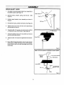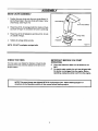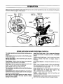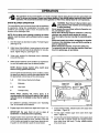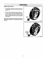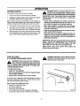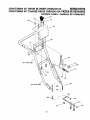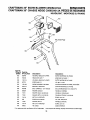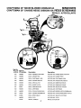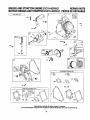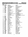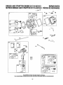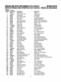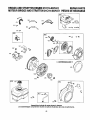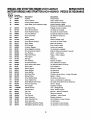
1
S _ARS
Owners
manual
Model
C950524312A
11.5 H.P, 30 inch
DUAL STAG
SNOW BLOWER
CAUTION:
You must read and
understand
this owner's
manual before operating
unit.
Serial No.
401428
SEARS CANADA INC., TORONTO, ONTARIO M5B 2B8
Printed
inU.S.A.
RULES FOR SAFE OPERATION
General Information
HazardSymbolsend the meanings
Thisinstruction
bookiswritten
fora personwithsomemechanical
ability.
Ukemostservicebooks,notallthestepsaredescribed.
Stepson howto
loosenortightenfastenersarestepsanyone
canfollowwithsome
mechanicalability.
Readandfollowtheseinstructions
beforeyouusethe
unit.
Thesesymbols
areusedonyourequipment
anddefinedinYouroperating
manual.
Reviewandunderstand
themeanings.
Theuseofoneof these
symbols
combined
witha signalwordwillalertyoutopotential
hazards
andhowtoavoidthem.
Knowyourproduct:Ifyouunderstand
theunitandhowtheunit
operates,
youwillgetthebestperformance.
Asyoureadthis manual,
compare
the illustrations
totheunit.Leamthe location
andthefunctionof
thecontrols.
Tohetpprevent
anaccident,
fellowtheoperafing
instructions
andthesafetyrules.Keepthismanualforfuturereference.
IMPORTANT:
Manyunitsarenotassembled
andaresoldincartons.
Itis
theresponsibility
oftheownertomakesuretheassembly
instructions
in
this manualareexactly
followed.
Otherunitsarepurchased
inan
assembled
condition.
Onassembled
units,itistheresponsibility
ef the
ownertomakesuretheunitiscorrectly
assembled.
Theownermust
carefully
checktheunitaccording
totheinstrustions
inthismanualbefore
it isfirstused.
,_
Safety
Identifies
safety
Information
hazardsAlert
that - can
result in
personal
Injury, about
_]]]
perator's
Manual any
- Read
and or
understand
before
performing
activity
running
equipment.
_
RutaUng auger
Fire
Rotating impeller
_
Explosion
Toxic fumes
Shock
,_1_
Thismanual
contains
safetyinformation
tomake
you
awareofthehazards
anddsks
associated
withsnow
throwers,
andhowtoavoidthem. Thesnowthrower
isdesigned
and
intended
forremoval
ofsnow,andshould
not beusedforanyother
purpose,
it isimportant
thatyoureadandunderstand
these
instructions,
andanyone
operating
theequipment
readand
understand
theseinstructions.
li_
Rotating gears
HotSu_ace
/_
•
,_WARNING
Theengineexhaust
fromthisproduct
contains
chemicals
known
tothe
StateofCalifornia
tocausecancer,birthdefects,orotherrepmducUve
harm.
A signalword(DANGER,WARNING,or CAUTION)isusedwiththealert
symbol
toindicate
thelikelihood
andthe potential
severity
ofinjury.In
addition,
a hazardsymbol
maybeusedtorepresent
thetypeofhazard.
14._?
DANGERindicates
a hazardwhich,ifnotavoided,
willresultin
deathor seriousInjury.
_1=
WARNINGindicates
a hazardwhich,ifnotavoided,
couldresult
in deathor seriousInjury.
_.
CAUTIONindicates
a hazardwhich,if notavoided,
mightresult
in minoror moderateinjury.
CAUTION,whenusedwithoutthealertsymbolindicates
a
sifuatonthatcouldresultIn damagetothe equipment,
remove
Shot off spark
engineplug
and
connector before
pertormlng maintenance
or repair work.
(_
2
Keep the
from
a safe
equlpmenL
distance
rotating
parts,Into
ever reach
_
:_mt.
,_
Thrown objects
protection for
Recommended
extended use. ear
RULES FOR SAFE OPERATION
OperatingSymbolsand their meanings
These symbolsare usedon yourequipmentenddefinedin youroperating
manuel. It is importantthat youreviewand understandthe meanings.
Failureto understandthe symbolsmightresultin harmto you.
Oil
_,_
Forward
Fuel
On Off
J_
_\_
N
Neutral
Reverse
Primerbulb
Throttle
I+1 Ch.oo
Ch.on
(_
Ignition On
(_
Ignition Off
Ignition
_DANGER
-_
Slow
Fast
Pushto
engage
electric start
_)
Electric
Start
Engage
(_
Engine
Start
Traction
_)
Engine Run
Auger Collector
_
Engine Off
Auger Clutch
Drive Clutch
_
Heated Grips
Engage
_-_
Disengage
Discharge Chute
LEFT
• Neverattempttodearaugerofdebdsorclogged
snowwhJeequipment
is
engagedorengineis running.
Cloggedorblocked
augersstoreenergy
andcanrotateunexpectedly,
EVENWITHENGINEOFf
• Stopengineanddisconnect
sparkplugwirewhenperforming
maintenance
onequipment.
• Neverleavetheequipment
unattended
whileengineisrunning.
Nways
disengage
theaugerendtraction
controls,
stopengine,andremovekeys.
• Keepchildren,
pets,andothersoutofthe areadudngoperation.
Children
areo_enattracted
totheequipment.
Beminclfut
ofallparsonspresent.
• Keepalllooseclothingfarawayfromfrontofsnowthrowerendauger.
Scarves,mittens,dangling
drawstdngs
looseclothesandpantscan
qucklybecomecaughtintherotatingdeviceanddismemberment
will
occur."fieuplonghairendremovejewelry.
• Thesnowthrower
isintendedtoremovesnowonly.Donotusefor
purposes
otherthenwhatisintended.
• Donotclearsnowacmssthefaceofslopes.Exercise
extremecaution
when
changing
direction
onslopes.Donotattempttoclearsteepslopes.
• Donotusethesnowthroweronsurfacesabovegroundlevelsuchas reefs
ofresidences,
garages,perchesorothersuchstructures
orbuildings.
Key
Stop
_/_
_kDANGER
RIGHT
Chute Deflector
UP
DOWN
• Unclogging
thedischarge
chuteisa hazardous
activity.
Clogged
or
blockedaugersstoreenergyendcan rotateunexpectedly.
• Neverplacehandsin orneardischarge
chute.
• WithengineOFF,waitforall movingpartstoceasemovement,
thenwitha
stick,clearthechute.Evenwithengineoff,partsmayrotateend
dismemberment
canoccur.
• Cloggedsnowcanhideotherobstructions
inthechuteandcausedamage
totheequipment,
impellerorauger.Takeprecautions
whenrestating
the
equipment
altersnowremoval.
RULES FOR SAFE OPERATION
_I=DANGER
,_WARNING
WHEN ADDING FUEL
• Beawareofyourenvironment
whileoperating
equipment.
Running
over
itemssuchas,gravel,doormats,
newspapars,toys,androckshidden
undersnow,canallbethrownfrom chuteorjamintheauger.
• Alwaysbeawareofthedirection
the snowisbeingthrown.
Nearby
pedestrians,
petsor property
maybeharmedbyobjectsbeingthrown.
• Familiarize
yourself
withtheareayouplantowork.Markoffbeundadasof
walkwaysanddriveways
topreventproperty
damagefromthrownobjects.
• Takecaution
whensnowthrowinginunfamiliar
areas.Stayalertforhidden
hazardsandtraffic.
• Afterstdkinga foreignobject,turnengineOFF,w_ for movingpartsto
ceasemovement,
andcheckimmediately
fordamage.If damaged,repair
beforestarting
andoperating
snowthrower.
• W'dhengineOFF,waitformovingpadsto stopandalwaysusea stickto
cleardischarge
chute.
• If unitvibratesaboormally,
turnengineOFRVibration
isgenerally
a
warningoftrouble.Seaanauthorized
dealerif necessary
for repairs.
• TurnengineOFFandletenginecoolat least2 minutesbeforeremoving
gascap.
• RIIfueltankoutdoors
or inweli-ventilatad
area.
• Donotoverfill
fuel tank.
• Keepgasolineawayfromsparks,openflames,pilotlights,heat,andother
k3nition
sources.
• Checkfuellines,tank,cap,andfittings
frequentlyfor cracksor leaks.
Replaceifnecessary.
WHEN STARTING ENGINE
•
•
•
•
Makesuresparkplug,muffler,fuel capandaircleanerarein place.
Donotcrankenginewithsparkplugremoved.
fffuelspills,waituntilit evaporates
beforestarting
engine.
if enginefloods,setchoketoOPEN/RUNpostiion,
placethrottleinFAST
andcrankunfitenginestarts.
WHEN OPERATINGEQUIPMENT
• Donot chokecarburetor
to stopengine.
WHEN TRANSPORTING EQUIPMENT
• Transport
withfueltank EMPTY.
WHEN STORING GASOLINEOR EQUIPMENT WITH FUEL IN TANK
• Storeawayfromfurnaces,stoves,waterheatersor otherap_liancas
that
havepilotlightorotherignitionsourcebecause
theycanignitegasaline
vapors,
• Keephandsandfeetawayfromrataitnggears.
• "fieuplonghairandremovejewelry.
• Donotwearloose-fitting
_thing, dangling
drawstrings
oritemsthatcould
becomecaught.
_I=WARNING
• Startandrunengineoutdoors.
• Donotstartorrunenginein enclosed
area,evenif dooms
or
windows
areopen.
• Ifthereisnaturalor LPgasleakageIn area,donotstartengine.
• Donutuseprassodzed
staringfluidsbecausevaporsareflammable.
WARNING
&WARN,NG
• Allowmuffler,enginecylinder
andfinstocoo_beforetouching.
• Removeaccumulated
combustibles
from mufflerareaandcylinder
area.
• Installandmaintain
in working
ordera sparkarresterbeforeusing
equipment
onforest-cavered,
grass-cavered,
brush-cavared
unimproved
land.ThestateofCalifornia
requiresthisSection4442of
the California
PublicResources
Cede. Otherstatesmayhavesimilar
laws.Federalewsapplyonfederalland.
BEFORE PERFORMINGADJUSTMENTS OR REPAIRS
• Disconnect
sparkplugwireandkeepit awayfromsparkplug.
WHEN TESTING FOR SPARK
• Useapproved
sparkplugtester.
• Donotcheckfor sparkwithsparkplugremoved.
OWNER'S INFORMATION
DATE PURCHASED:
Horse Power
11.5 HP
MODEL NO:
Displacement
305 cc
SERIAL NO:
Gasoline Capacity
3 quarts (2.8 litre)
Oil Capacity (5W30)
28 oz. (0.82 litres)
Spark Plug: (Gap .030 in.)
Champion RC12YC
Bore
3.120 in (79 mm)
Stroke
2.438 in (62 mm)
0.010-0.014in
(0.25-0.36 mm)
STORE WHERE PURCHASED:
ADDRESS:
CITY:
PROVINCE:
TELEPHONE :
_Recordthis information about your unit so that you will
be able to provide it in case of loss or theft.
Armature Air Gap
IT ire Pressure
* See side ofthe tirefor maximuminflation.Do notexceed the
maximumpressure on the tire wall.
MAINTENANCE
AGREEMENT
CUSTOMER
The Craftsman Warranty, plus a Maintenance
Agreement, provide maximum value for Sears
products. Contact your nearest Sears store for details.
RESPONSIBILITIES
Read and observe the safety rules.
Follow a regular schedule in maintaining, caring for and
using your snow blower.
Follow the instructions under "Customer Responsibilities"
and "Storage" sections of this owner's manual.
WHEELED SNOW BLOWER
LIMITED
TWO
(2)YEAR
WARRANTY
ON CRAFTSMAN
SNOW
BLOWER
For two (2) years from date of purchase, Sears Canada Inc. will repair or replace free of charge, at Sears option, parts
which are defective as a result of material or workmanship.
COMMERCIAL
OR RENTAL USE:
Warranty on snow blower will be 90 days from date of purchase if used for commercialor rental purposes.
THIS WARRANTY
DOES NOT COVER:
1. Pre-delivery set-up.
2. Expendable items which become worn duringnormal use, such as belts, spark plugs,filter,shear pinsas well as damages to the engine resulting from operating the snow blower with insufficientoil.
3. Tire replacement or repair caused by puncturesfrom outside objects, such as nails, thorns, stumps or glass.
4. In home service.
Warranty service is available by returning the Craftsman snow blower to the nearest Sears Service Centre/Department
in Canada. This warranty applies only while this product is in use in Canada.
This warranty is in addition to any statutorywarranty and does NOT exclude or limit legal rights you may have but shall
run concurrently with applicable provincial legislation. Furthermore, some provinces do not allow limitations on how Ion
an implied warranty will last so the above limitations may not apply to you.
SEARS CANADA INC., TORONTO, ONTARIO M5B 2B8
5
TABLE OF CONTENTS
HAZARD SYMBOLS AND THE MEANINGS
..........
2
OPERATING TIPS ..............................
19
OPERATING SYMBOLS AND THEIR MEANINGS .....
3
SERVICE RECOMMENDATIONS
...................
20
OWNER'S INFORMATION ..........................
5
CUSTOMER RESPONSIBILITIES
..................
21
ASSEMBLY .......................................
7
TOOLS REQUIRED FOR ASSEMBLY ..............
7
CONTENTS OF SHIPPING CARTON ..............
7
PARTS BAGS CONTENTS: .......................
7
UNPACKING ....................................
8
UPPER HANDLE AND CRANK ASSEMBLY .........
9
CHECK THE CABLES ............................
9
HOW TO SET THE LENGTH OF THE CABLES .....
9
SPEED SELECT LEVER ........................
10
SNOW CHUTE ASSEMBLY ......................
11
OPERATION .....................................
OPERATING CONTROLS
.......................
12
SNOW BLOWER ...............................
21
LUBRICATION AT STORAGE ....................
21
LUBRICATION - EVERY 10 HOURS ..............
21
LUBRICATION - EVERY 25 HOURS ..............
22
ENGINE .......................................
23
ADJUSTMENT/REPAIR
...........................
AUGER HOUSING HEIGHT ADJUSTMENT
24
.......
24
TO ADJUST SCRAPER BAR .....................
24
TO ADJUST SKID HEIGHT ......................
24
HOW TO REMOVE THE SNOW HOOD ...........
25
BELTADJUSTMENT ............................
26
HOW TO REPLACE THE BELTS .................
27
BELT GUIDE ADJUSTMENT .....................
30
12
SNOW BLOWER OPERATION ...................
13
WHEEL LOCK OUT PIN .........................
14
BEFORE STARTING ENGINE ....................
15
CHECK THE OIL ...............................
15
FILL GAS ......................................
15
BEFORE STOPPING THE ENGINE ...............
TO STOP ENGINE ..............................
HOW TO CHECK AND ADJUST THE CABLES
....
30
AUGER DRIVE CABLE ADJUSTMENT ............
30
TRACTION DRIVE CABLE ADJUSTMENT .........
31
16
HOW TO ADJUST OR REPLACE
THE FRICTION WHEEL .......................
32
16
AUGER SHEAR BOLT REPLACEMENT ...........
35
TO START ENGINE ............................
.16
STORAGE .......................................
36
FROZEN STARTER ............................
.18
TROUBLE SHOOTING CHART .....................
37
HOW TO CLEAR A CLOGGED DISCHARGE CHUTE .18
REPAIR PARTS ..................................
38
HOW TO USE THE CLEAN-OUT TOOL ..........
ORDER REPAIR PARTS ...........................
67
.18
ASSEMBLY
TOOLS REQUIRED FOR ASSEMBLY
CONTENTS
1 - Knife
1- Snow Blower
2
2
2
1
1
1- Container of Fuel Stabilizer (Located in Parts Bag)
-
1/2" wrenches (or adjustable wrenches)
9/16" wrenches (or adjustable wrenches)
3/4" wrenches (or adjustable wrenches)
3/8" wrenches (or adjustable wrenches)
Pair pliers or screw driver (to spread cotter pin)
OF SHIPPING CARTON
1- Snow Chute Assembly
1- Crank Assembly
1- Parts Bag
HOW TO MEASURE SCREW SIZE
LENGTH
_
DIAMETER
_b
WARNING: Always wear safety glasses or eye
shields while assembling snow blower.
PARTS BAGS CONTENTS:
* 2-1/4-20
x 1.75
"2-Spacer
* 2H-Jx/4n"u20
O
©
* 2 - Wrenches
2- Shifter Knobs
*Non Assembly parts are found in toolbox located on top of belt cover.
7
ASSEMBLY
Figure 1 shows the snow blower in the shippingposition.
Figure 2 shows the snow blower completely assembled.
Reference to right and left hand side of the snow blower is
from the operator's position at the handle.
UNPACKING
1.
Locate the two tear tabs at the bottom of the carton,
2.
Pull the tear tape no more than twelve inches (30.48cm.)
at a time. Re-grasp tape next to the carton and pull
again. Repeat until all the tape is torn off.
Auger Drive
Clutch Lever
Traction Drive
Traction
Drive Cable
Assembly
3. After the tape has been completely removed from the
carton, remove the carton from the base. Cut all four corners and fold the sides toward the center for easy disposal.
4.
Speed
Selector
Lever
Auger
Drive
Cable
J
Crank
Assembly
Snow Chute
Deflector
Remove the plastic bag that covers the unit.
_rHousing
5.
Locate and remove the parts bag.
NOTE: Set the fuel stabilizer aside until adding
gasoline to the fuel tank. We recommend that fuel
stabilizer is added to the fuel each time that gasoline
is added to the fuel tank.
Screw
6.
7.
For shipping purposes, the height adjust skids are attached to the pallet. Remove the screw that secures
each height adjust skid to the pallet. (See Figure 2).
Skid
Figure 2
Roll the snow blower off the carton by pulling on the lower
handle.
CAUTION: DO NOT back over cables.
Traction Drive Lever
8.
Remove the packing materialfrom the handle assembly.
Cable
\
9.
Cut ties securing the clutch control cables to the lower
handle.
NOTE: If the cables have become disconnected from the
clutch levers, reinstall the cables as shown in Figure 3.
Figure 3
ASSEMBLY
UPPER HANDLE AND CRANKASSEMBLY
[/
Adaptor Boot!
1.
2.
Loosen, but do not remove the screws, flatwashers, lockwashers and hex nuts in the upper holes of the lower handle.
f
_
Flatwashe_
\
F
Lockwasher_
D, Locknut
Remove the fasteners and the crank assembly eyebolt
from the lower holes of the lower handle.
!
Bo_
\
3.
Raise upper handle into operating position. Upper handle should be to the outside of the lower handle.
Eye Bolt
\
Flatwasher
Fiatwasher
Figure 4
NOTE: Make sure the cables are not caught between
the upper and lower handle.
4.
Install the fasteners and the crank assembly eyebolt that
were removed in step 2. DO NOT tighten until all fasteners are in place.
5.
Attach the crank rod to the universal joint assembly with
the hair pin (see Figure 5).
6.
Tighten nut on eye bolt. Make sure eye bolt is properly
aligned and the crank can freely rotate.
7.
Tighten all handle bolts.
Assembly
NOTE: Make sure crank does not touch carburetor
cover.
Universal Joint
CHECKTHECABLES
Traction Drive Cable
1.
If control cables have become unattached from motor
mount frame, reconnect cables as shown in Figure 6.
2.
For cable adjustments, see "How To Check And Adjust
The Cables" in the ADJUSTMENT/REPAIR section.
HOW TO SET
THE LENGTH OF THE CABLES
The cables were adjusted at the factory and no adjustments
should be necessary. However, after the handles are put in
the operating position, the cables can be too tight or too
loose. If an adjustment is necessary, see "How To Check And
Adjust The Cables" in the Service And Adjustment section.
9
Auger Drive Cable
Figure 5
ASSEMBLY
SPEED
1,
SELECT
LEVER
Cut plastic tie securing speed select lever assembly to
the shifter bracket. (See Figure 7)
Shifter Bracke_
2.
Remove Iocknut, washer, spring, and the bolt.
Figure 9)
(See
3.
Position speed selector lever assembly as shown in
Figure 8.
4.
Reinstall bolt, spring, washer and Iocknut. (See Figure 9)
5.
Tighten Iocknut until 1/8 to 3/16 inch of the bolt threads
protrude past the locknut.
6.
Thread the 3/8-16" hex jam nut onto the lever until the
nut reaches the end of the thread. (See Figure 9)
7.
Thread the plastic knob as far as possible and ensure
that the knob points forward.
8.
Tighten the 3/8-16" hex jam nut against the knob securely.
9,
Move shifterthroughall speeds to ensure proper tension
of the spring. If shifter lever sticks in any of the notches,
loosen Iocknut 1/2 turn at a time until shifter lever moves
more freely.
Figure7
Control Panel
Figure 8
NOTE: View is trorn rightside of unit standing in operator's position.
Plastic Knob"_,_-'_
(pointed
forward)
3"8
(.J--_//
_
6"
"
/ -1 Hex,Jam Nut
Shifter Bracket
Control Panel
Lccknut
1/8 to 3/8 inch of
Spring
Figure 9
lO
ASSEMBLY
SNOW
1.
CHUTE
ASSEMBLY
Positionthe snow chute onto the snow chute flange, Align the three holes in the snow chute with holes in snow
chute flange. (See Figure 10)
Chute Extension
\
Snow Chute Deflector
2,
Place three 5/16-18 carriage boltsfrom inside of chute
as shown in Figure 10. (hardware is found in parts bag)
3.
Place three 5/16-18 flatwashers and three 5/16-18 nuts
on outside of flange.
4.
Carriage Bolts
"-"'-
Flatwasher
Tighten all carriage bolts securely.
Flange
Figure 10
NOTE: DO NOT overtigten carriage bolts.
CHECK THE TIRES
IMPORTANT!
OPERATING
The tires were over inflated for shipment. Check the tire
pressure in the tires. See the sidewall of the tire for the
proper inflation.
BEFORE
YOU
START
Check the fasteners. Make sure all fasteners are
tight.
O
On electric start models, the unit was shipped with
the starter cord plugged into the engine. Before
operating, unplug the starter cord from the engine.
NOTE: This snow blower was shipped WITH OIL in the engine. See "Before Starting Engine" instructions In the Operation section of this manual before starting engine.
11
I
OPERATION
Get to know your snow blower and its controls. Be sure you (or any other operator) have read and understoodthe Operation
Precautions listed on page 2 of this manual.
Choke
Control
Gas Tank
Auger Drive
Clutch Lever
Primer Button
Traction Drive
Clutch Lever
\
Traction Ddve
Cable
Crank
Assembly
Deflector
Safety Key
Height
Adjust Skid
Figure 11
ENGINE AND SNOW BLOWER OPERATING
The engine operating controls and their functions are as
follows:
CONTROLS
Auger Drive Clutch Lever- Used to engage and disengage
the auger and impeller.To engage push down, to disengage
release.
Choke Control- Set choke controlto ON CHOKE position
to start a cold engine.
Electric Start Button- Used to start the engine using the
120 volt electric starter.
Traction Drive Clutch Lever- Used to propel snow blower
forward or reverse. Push down to engage, release to
disengage.
Prime Button- Used to inject fuel directly into carburetor
manifoldto insure fast starts in cool weather.
Snow Chute Deflector- Changes the direction the snow is
blown.
Safety Key- Must be inserted into ignitionkey slot to start
engine. Pull out to stop. Do not turn safety key.
Starter Handle- Starts the engine manually.
Crank- Used to change direction of the snow discharge.
Turn handle clockwise to turn chute to right. Turn handle
counter clockwise to turn chute to left.
The snow blower operating controls and their functions
are as follows:
Height Adjust Skid- Used to adjust ground clearance of
auger housing (see To Adjust Skid Height in the
Adjustment/Repair section of this manual).
Speed Select Lever- Allows the operator to use one of six
(6) forward and two (2) reverse speeds.To shift,move speed
select lever to desired position.
Toolbox - Spare shear pins, shear bolt wrenches and
spacers are located in toolbox.
NOTE: Do not move speed select lever while Traction
Drive Clutch is engaged. This may result in severe
damage to drive system.
12
Clean-Out Tool - Use the clean-outtoolto remove snow and
debirs from the discharge chute and the auger housing.
OPERATION
result
The
operation
in severeofeye
anydamage.
snow blower
Alwayscan
wear
result
safety
in foreign
glassesobjects
or eye shields
being thrown
before into
beginning
the eyes,which
snow blower
can
Operation. We recommend standard safety glasses or Wide Vision Safety Mask for over spectacles.
SNOW BLOWER OPERATION
,_
WARNING:
Read
Owner's
Manual
before
operating machine.
This
machine
can be
dangerous
if used carelessly.
Never operate the snow blower without all guards, covers, and shields In place.
Never direct discharge towards windows or allow bystanders near machine while engine is running.
Stop the engine whenever leaving the operating position.
The most effective use of the snow blower willbe established
by experience, taking into consideration the terrain, wind
conditions and building location which will determine the
direction of the discharge chute.
NOTE: Do not blow snow towards a building as hidden
objects could be blown with sufficient force to cause
damage.
1.
Start the engine as described in section"To Start Engine"
(see Figure 13).
2.
Adjust snow chute deflector. Loosen wingnut on the side
of the snow chute and raise chute deflector for more distance. Tighten wing nut. (see Figure 12).
3.
Using crank, position the discharge chute to discharge
snow with the wind.
4.
Select proper speed for snow conditions as outlined below and set speed select lever to desired position.
Disconnect spark plug before unclogging the impeller
housing or the discharge chute and before making repairs or adjustments.
When leaving the machine, remove the safety key.
To reduce the risk of fire, keep the machine clean and
free from spilled gas, oil and debris.
Tee Knobs
NOTE: Always release traction drive clutch lever
before moving speed select lever.
Ground speed is determined by snow conditions. Select
the speed you desire by moving the speed selector into
the appropriate colored area on the control panel.
1-2
Wet, Heavy, Slushy, Extra Deep
3
Moderate
4-5
Very Ught
6
Transport Only
Figure 12
Traction Ddve
Auger Drive
ged
Disengaged_
.._._
ClutchLever
is_l_ a
NOTE: When clearing wet, heavy snow, it is
recommended that the ground speed of the unit be
reduced and do not attempt to clear the full width of
the unit.
Engaged
For additional operating instructions see "Operating
Tips" in this section of the manual.
5.
6,
'_
J
Engaged
Figure 13
Engage auger drive clutch lever (right hand-Figure 13).
7.
To stop forward motion, release traction drive clutch lever
(left hand - Figure 13).
IMPORTANT: Be sure front of unit is clear of
bystanders or obstacles before operating.
8.
To stop auger, release auger drive clutch lever (right
hand - Figure 13).
Engage traction drive clutch lever (lefthand-Figure 13).
As the snow blower starts to move, maintain a firm hold
on the handles and guide the snow blower along the cutting path. Do not attempt to push the snow blower.
g. To move the snow blower backwards, move speed select
lever into first or second reverse and engage traction
drive clutch lever (left hand). To stop, release traction
drive clutch lever.
13
OPERATION
WHEEL LOCK OUT PIN
1. The rightwheel is secured to the axle with a klickpin. This
unit was shipped with this klick pin in the locked position.
(Figure 14).
2.
For ease of maneuverability when lighter conditions prevail, remove klick pin from wheel locked position and insen into single wheel drive (unlocked) position
(Figure 15). Make sure that the klick pin is in the single
wheel drive position of the axle only and not through the
locked position.
Locked
Position
NOTE: Check tire pressure (24 pounds). See side of tire
for maximum inflation, Do not exceed listed maximum
pressure.
Figure 14
Single Wheel
Drive Position
(Unlocked)
Figure 15
14
OPERATION
BEFORE STARTING
ENGINE
1. Fill the fuel tank with fresh, clean, unleaded regular, unleaded premium, or reformulated automotive gasoline
with a minimum of 85 octane along with a fuel stabilizer
(follow instructions on fuel stabilizer package). DO NOT
use leaded gasoline. We recommend that fuel stabilizer
be added to the fuel each time that gasoline is added to
the fuel tank.
Check the oil
NOTE: The engine was shipped from the factory filled
with oil. Check the level of the oil Add oil as needed.
1,
Make sure the unit is level. Use a high quality detergent
oil classified "For Service SG, SH, SJ, SL, or higher".
2,
Remove the oil fill cap/dipstick and wipe with a clean
cloth (see Figure 16).
3.
Insert the oilfillcap/dipstick and turn clockwise to tighten.
4.
Remove the oil fill cap/dipstick and check the oil
NOTE: Winter grade gasoline has higher volatility to
improve starting. Be certain container is clean and
free from rust or other foreign particles. Never use
gasoline that may be stale from long periods of
storage in the container.
CAUTION: DO NOT use gasoline containing any
amount of alcohol as it can cause sedous damage to
the engine or significantly reduce the performance.
NOTE: Do not check the level of the oil while the
engine runs.
5.
If necessary, add oil until the oil reaches the FULL mark
on the oil fill/capdipstick (see Figure 16). Do not add too
much oil.
6.
caution
when
handling
or storingAlways
gasoline.
ARNING:
Gasoline
is flammable.
use
Turn engine off and let engine cool at least two
minutes before removing the gas cap. Do not add gasoline to the fuel tank while snow blower is running, hot,
or when snow blower is in an enclosed area. Keep away
from open flame, electrical sparks and DO NOT SMOKE
while filling the fuel tank. Never fill the fuel tank completely; but fill the fuel tank to within 1-1/2 inch (3.8 mm)
from the top to provide space for the expansion of the
fuel. Always fill fuel tank outdoors and use a funnel or
spout to prevent spilling, Make sure to wipe up any
spilled fuel before starting the engine.
Store gasoline in a clean, approved container, and keep
the cap in place on the container. Keep gasoline in a
cool well ventilated place; never in the house. Never
buy more than a 30 day supply of gasoline to assure
volatility. Gasoline Is intended to be used as a fuel for
internal combustion engines; therefore, do not use
gasoline for any other purpose. Since many children
like the smell of gasoline, keep it out of their reach because the fumes are dangerous to inhale, as well as being explosive.
_k
Tighten the fill cap/dipstick securelyeach time you check
the oil level.
NOTE: For extreme cold operating conditions of 0°F
(-18 ° C) and below, use a synthetic 5W30 motor oil for
easier starting.
NOTE: S.A.E. 5W30 motor oil may be used to make
starting easier in areas where the temperature is 20 ° F.
(-7 ° C) to O°F (-18 ° C). Synthetic 5W30 is acceptable for
all temperatures. DO NOT mix oil with gasoline,
NOTE: SEE CHART FOR OIL RECOMMENDATION
TEMPERATURE
0°F (-18 °
TYPE OF OIL
C) and above
S.A.E. 5W30
0°F (-18 ° C) and below
synthetic 5W30
Oil Fill
Cap/Dipstick
SAE VISCOSITY GRADES
=,- WJ JBJ
°F
°C
20
I
•
-30
0
I
i
-20
20
I
¶
-10
32
•
•
0
40
•
%
•
10
FILL GAS
This engine is certified to operate on gasoline. Exhaust
Emission Control System: EM (Engine Modifications)
Figure 16
15
OPERATION
BEFORE STOPPING
THE ENGINE
Run the engine for a few minutes to help dry off any moisture
on the engine.
TO STOP ENGINE
CAUTION: To stop the engine, do not move the choke
control to CHOKE position. Backfire or engine damage
can occur.
2.
1. Push the stop switch to the OFF position.
Pull out the safety key.
Safety Key
Stop Switch
Figure 18
Figure 17
TO START ENGINE
Be sure that engine oil is at FULL mark on the oil fill
cap/dipstick. The snow thrower engine is equipped with a 120
volt A.C. electric starter and recoil starter. Before starting the
engine, be certain that you have read the following
information.
_lb
WARNING:
electric
is equipped
with
a three-wire The
power
cordstarter
and plug
designed
to
operate on 120 volt AC house hold current. The
power cord must be properly grounded at all times to
avoid the possibility of electric shock which can cause
injury to the operator. Follow all instructions carefully
as set forth below:
Make sure your house has a three-wire grounded system. If you ere not sure, ask • licensed electrician. If
your house does not have a three-wire grounded system, do not use this electric starter under any condition.
If engine floods, set the choke to the OPEN/RUN position and
crank until the engine starts.
_lb
WARNING:
(kickback) will
Rapid
pullretraction
your handoforthe
armstarter
towardcord
the
engine faster than you can let go of the starter
cord.
• When starting the engine, slowly pull the starter cord
until resistance is felt. Then rapidly pull the starter
cord.
If your house has a three-wire grounded system but a
three hole receptacle is not available to connect the
electric starter, have a three-hole receptacle installed
by a licensed electrician.
• Make sure components; such as impellore, pulleys
or sprockets, are securely attached.
_IL
WARNING:
To connect
a 120 cord
volt power
always
connect
the power
first tocord,
the
switch box located on the engine and then plug
the other end into a three-hole grounded receptacle.
WARNING:
disconnect
the power
always unplugTothe
end connected
to thecord,
threehole grounded receptacle first.
16
OPERATION
Choke Knob
Primer
Safety Key
Starter Motor
Recoil Starter Handle
Stop Switch
Figure 19
How To Start A Cold Engine
1, Be sure auger drive and traction drive levers are in the
disengaged (RELEASED) position.
9.
2.
3.
Push thestop switch to the ON position (see Figure 19).
Push in the safety key.
4.
Rotate the choke knob to the CHOKE position.
10. Allow the engine to warm up for several minutes. As the
engine warms up, adjust the choke knob toward the
RUN position. Walt untilthe engine runs smoothly before
each choke adjustment.
5.
(Electric Start) Plug the power cord intothe starter motor on the engine. Plug the other end of power cord into
a three-hole, grounded 120 VOLT, AC receptacle.
6.
Push the primer button as specifiedbelow. Remove finger from primer button between pushes.
11. (Electric Start) First disconnect power cordfrom receptacle. Then, disconnectthe power cord from the switch
box.
If after following the preceding instructions,your engine fails
to start, have the engine checked by an Authorized Sears
Service Outlet.
• Push two times if temperutureis 15° F (-9 ° (3) or higher.
• Push four times if temperature is below 15° F (-9 ° C).
7,
If the engine does not start in 5 or 6 tries, See Difficult
Starting in the 'Troubleshooting Table".
NOTE: Do not lose the safety/ignition key. Keep the
safety/ignition key is a safe place. The engine will not
start without the safety/ignition key.
(Electric Start) Connect the power cord to the engine
and depress the starter button. To prolongthe life of the
starter, do not crank for more than 5 seconds at a time.
Wait one minute between startsto allowthe starter motor
to cool.
How To Start A Warm Engine
8.
(Recoil Start) Slowlypull the recoil starter handle until
resistance isfelt and then pull repidlyto start the engine.
Do not allow the recoil starter handle to snap back.
Slowly return the recoil starter handle.
If restarting a warm engine after a shortshutdown,leave the
choke lever in the off position and do not push the primer
button. If the engine fails to start, follow the Cold Start
instructions.
17
OPERATION
FROZEN
STARTER
closed,
poorly
ventilated
areas.indoors
Engineor
exhaust
WARNING:
Never
run engine
In encontains CARBON MONOXIDE, AN ODORLESS
AND DEADLY GAS. Keep hands, feet, hair and loose
clothing away from any moving parts on engine and
snow thrower.
,_
If the starter is frozen and will not turn engine:
1.
Pull as much rope out of the starter as possible.
2.
Release the starter handle and let it snap back against
the starter. Repeat until the engine starts.
Warm engines will cause condensation in cold weather. To
help prevent possible freeze-up of recoil starter and engine
controls, proceed as follows after each snow removal job.
• Engine parts, especially the muffler, become extremely hot. Severe thermal burns can occur on contact. Allow the engine to cool before touching.
• Never allow children to operate the snow thrower.
Never allow adults to operate the snow blower without proper instruction,
• Keep the area of operation clear of all persons, particularly small children and pets.
• Never leave the snow blower unattended while the
engine is running. Anyone operating the engine or
equipment must carefully read and understand the
operating instructions.
1. With engine off, allow engine to cool for several minutes.
2.
Pull starter rope very slowly until resistance is felt, then
stop. Allow the starter rope to recoil. Repeat three times.
3. With the engine not running, wipe all snow and moisture
from the carburetor cover in area of control levers. Also
move choke knob and starter handle several times.
IMPORTANT: After each use of the snow blower, stop the
engine, remove the safety/ignition key, remove all
accumulated snow from the snow blower and wipe
clean. Store the snow blower in a protected area.
NOTE: Never cover snow blower while engine and
exhaust area are still warm.
HOW TO CLEAR
A CLOGGED DISCHARGE
,a,
CHUTE
WARNING: Blockage must be cleared only after
shutting off the snow blower and only with a
clean-out tool, not by hand.
peller insideHand
the discharge
chute
the most
WARNING:
contact with
the is
rotating
imcommon cause of injury associated with snow
blowers. NEVER USE YOUR HAND TO CLEAN OUT
THE DISCHARGE CHUTE.
4_b
To Clear The Chute:
• SHUT OFF THE ENGINE!
• Wait 10 seconds to be sure that the impeller blades
have stopped rotating.
• Always use a clean-out tool, not your hands.
A clean-out tool is attached to either the handle or the top of
the auger housing (see Figure 20). Use the clean-out tool to
remove snow from the auger housing.
/_
How To Use The Clean-Out Tool
• Release the auger drive lever.
Pull cut the safety key.
• Disconnect spark plug wire.
Do not place your hands in the auger or discharge
chute. Use a clean-out tool to remove snow or debris.
Clean-out Tool
Figure 20
18
OPERATION
OPERATING
TIPS
1,
Most efficient snowblowingis accomplished when snow
is removed immediately after it falls.
2.
For complete snow removal, slightly overlap each swath
previously taken.
3.
Snow should be discharged downwind whenever possible.
4.
5.
6,
After the snowblowingjob has been completed, allow the
engine to idle for a few minutes, to melt snow and ice accumulated on the engine.
7.
Clean the snow thrower
8.
Remove ice and snow accumulation and all debris from
the entire snow thrower, and flush with water Ofpossible)
to remove all salt or other chemicals. Wipe snow thrower
dry.
9,
Before starting snow blower, always inspectaugers and
impeller for ice accumulation and/or debris, which could
result in snow blower damage.
For normal usage, set the skids one-eighth inch (3 mm)
below the scraper bar, For extremely hard-packed snow
surfaces, the skids may be adjusted upward to insure
cleaning efficiency.
On gravel or crushed rock surfaces, the skids should be
set at 1-1/4 inch (32 mm) below the scraper bar (see To
Adjust Skid Height, in the Adjustment/Repair section in
this manual). Rocks and gravel must not be picked up
and thrown by the machine.
thoroughly
after each use.
10. Check oil level before every start. Make sure the oil is at
the FULL mark on the oil fill cap/dipstick.
19
SERVICE RECOMMENDATIONS
SERVICE
PROCEDURE
S
N
O
W
B
L
BEFORE
EACH
USE
EVERY
8
HOURS
EVERY
10
HOURS
EVERY
25
HOURS
EVERY
50
HOURS
EVERY
100
HOURS
BEGINNING
EACH
BEFORE
SEASON STORAGE
]]ghtenall screwsand
nuts
Check Traction Clutch
Cable Ad ustment
See Cab e Ad ustment)
q
Check Auger clutch Cable
\d ustment
See Cab e Ad ustment)
q
O Adjust Drive Belts
W
E
FIRST
2
HOUR
RECOMMENDATIONS
q
q
Lubricate Chains and
Hex Shaft
R
Lubricate Auger Shaft
See Shear Bolt Replacement)
E
N
G
I
N
Oil, Check
q
q
q
q
Oil, Change
Check and Clean Spark
Plug
E iReplace Spark Plug
.j
Clean and Inspect Spark
Arrestor
AFTER EACH USE
The warranty on this snow blower does not cover itemsthat
have been subjected to operator abuse or negligence. To receive full value from the warranty, operator must maintain
snow blower as instructed in this manual. The following Service Recommendations
is supplied to assist operator to
properly maintain snow blower. This is a check list only. Adjustment referred to will be found in Adjustments/Repairs
section of this manual.
Maintenance, replacement, or repair of the emission control
devices and systems can be performed by any non-road engine repair establishment or individual. Regular maintenance
will improve the performance and extend the life of the engine.
2O
1.
Check for any loose or damaged parts.
2.
"lighten any loose fasteners.
3.
Check and maintain the auger.
4.
After each use, remove all snow and slush off the snow
blower to prevent freezing of auger or controls.
5.
Check controls to make sure they are functioningproperly.
6.
If any parts are worn or damaged, replace immediately.
CUSTOMER RESPONSIBILITIES
Some adjustments will need to be made periodically to
properly maintain your snow blower.
All adjustments in ADJUSTMENTS/REPAIRS section of this
manual should be checked at least once each season.
SNOW BLOWER
The following adjustment should be performed more than
once each season.
Auger and Traction Drive Belts shouldbe adjustedafterthe
first 2 to 4 hours of use, again about mid-season and twice
each season thereafter(See To AdjustBelts paragraph in the
Adjustment/Repair sestion).
AS REQUIRED
Auger Gear Box
The auger gear box is lubricated at the factory and shouldnot
require additional lubrication.
If fQrsome reason the lubricant should leak out, or ifthe auger
gear box has been serviced, add Lubriplate GR132 Grease
or equivalent. Maximum 3-1/4 ounces, (92 grams) should be
used.
Remove filler plug D (Figure 21 and Figure 22), once a year.
If grease is visible, do not add. If grease is not visible, use a
piece of fine wire, like a dipstick to check if there is grease in
the gear box. Mobilux EP1 and Shell Aldania EP1 are
suitable equivalents.
Filler
Plug
Figure 22
LUBRICATION
AT STORAGE
Bearings and bushings
If grease or oil comes into contact with the disc drive plate or
friction wheel, make sure to clean plate and wheel thoroughly
with a alcohol base solvent.
All bearings and bushings are lifetimelubricatedand require
no maintenance.
Hex shaft and chains
LUBRICATION
For storage, the hex shaftshould be wiped with a cloth lightly
moistened with motor oil to prevent rusting (see Figure 24).
- EVERY
10 HOURS
1. Auger Shaft - Using a hand grease gun, lubricatethe
auger shaft zerk fittings (A) every ten (10) operating
hours. Each time a shear bolt is replaced, the auger shaft
MUST be greased (Figure 21). (See To Replace Auger
Shear Bolt in the Repair/Adjustment section).
For storage, the chains should be lubricated with a chain type
lube. (see Figure 24).
NOTE: Any greasing or oiling of the above mentioned
components can cause contamination of the rubber
friction wheel. If the disc drive plate or friction wheel
come in contact with grease or oil damage to rubber
friction wheel will result.
2.
21
For storageor when replacing shear bolts, remove shear
bolts and lubricate auger shaft zerks. Rotate augers several times on the shaft and reinstall the shear bolts.
CUSTOMER RESPONSIBILITIES
LUBRICATION
- EVERY 25 HOURS
Chute Rotation Gear
Lubricatethe chute rotation gear with automotivetype oil,
(see Figure 23).
Figure 22
Chains
4.
5.
1. Position speed selector lever in first (1) forward gear.
2. Stand the snow blower up on the auger housing end.
3.
Lubricate the chains with a chain type lubricant.
Wipe the hexshaft and sprockets with 5W30 motoroil,
NOTE: Clean all excess grease or oil found on the
rubber friction wheel or the disc drive plate.
NOTE: When the crank case if filled with oil, do not
leave the snow blower standing up on the auger
housing for an extended period of time,
Remove the bottom panel.
6.
CAUTION: Do not allow grease or oil to contact the
rubber friction wheel or the disc drive plate,
Install the bottom panel,
t in
contact with grease or oil
ge to rubber friction wheel
will result,
If grease or oil come in contact with
the disc drive plate or friction wheel,
make sure to cJeanthe plate and
wheel thoroughlywith a alcohol base
solvent.
"!
Figure 24
22
CUSTOMER RESPONSIBILITIES
ENGINE
TEMPERATURE
0°F (-18 °
TYPE OF OIL
C) and above
S.A.E. 5W30
POWER RATINGS
0°F (-18 ° C) and below
The power ratingsfor an individualengine model are initially
developed by starting with SAE (Society of Automotive
Engineers) code J1940 (Small Engine Power & Torque
Rating Procedure) (Revision 2002-05). Given both the wide
array of products on which our engines are placed, and the
variety of environmental issues applicable to operating the
equipment, it may be that the engine you have purchased will
not develop the rated horsepower when used in a piece of
power equipment (actual "on-site" power). This difference is
due to a variety of factors including, but not limited to, the
following: differences in altitude, temperature, barometric
pressure, humidity, fuel, engine lubrication, maximum
governed engine speed, individual engine to engine
variability, design of the particular piece of power equipment,
the manner in which the engine is operated, engine run-in to
reduce friction and clean out of combustion chambers,
adjustments to the valves and carburetor, and other factors.
The power ratings may also be adjusted based on
comparisons to other similar engines utilized in similar
applications, and will therefore not necessarily match the
values derived using the foregoing codes.
synthetic 5W30
SAE VISCOSITY GRADES
°F
20
0
II
i
°C
-30
20
I
II
l
•
-20
-10
32
40
s
s
l
l
0
Oil Fill Cap/Dipstick _
10
_
b
F 'LL
Check Crankcase Oil Level before starting engine and after
each 8 hours of continuous use (see Figure 25). Add the
recommended motor oil as required.
NOTE: Overfilling the engine can affect performance.
Tighten the oil fill cap securely to prevent leakage.
NOTE: OII level must be at FULL mark.
Change Oil every 50 hours of operation or at least once a
year, even ifthe snow blower is not used for fifty hours_ Use
a clean, highquality detergentoil. Fillthe crank case to FULL
line on dipstick(see Figure 25). Be sure originalcontainer is
marked: A.P.I. service "SF" or higher.Do not use SAE10W40
oil (as it may not provideproper lubrication).See Chart for oil
recommendations.
25
-,uC=*ure
Oil Fill cap/Dipstick
To Drain Oil - Positionsnow blower so that the oil drain plug
is lowest point on engine. When the engine is warm, remove
oil drain plug and oil fill cap and drain oil into a suitable
container (Figure 26).
Replace oil drain plug and tighten securely. Refill crank case
with the recommended motor oil.
Figure 26
23
ADJUSTMENT/REPAIR
To adjust skids, proceed as follows:
_lb
WARNING:
turn the
unitspark
off, remove
tion
key andAlways
disconnect
plug wireignibefore making any repairs or adjustments.
AUGER HOUSING HEIGHT ADJUSTMENT
TO ADJUST
SCRAPER
1.
Place a block (equal to height from ground desired) under scraper bar near but not under skid.
2.
Loosen skid mounting nuts (Figure 27) and push the skid
down until it touches the ground. Retightsn mounting
nuts.
3.
Set skid on other side at same height.
BAR
After considerable use, the metal scraper bar will have a
definite wear pattern. The scraper bar in conjunction with the
skids should always be adjusted to allow one-eighth of an
inch (3 mm) between the scraper bar and the sidewalk or
area to be cleaned.
NOTE: Make sure that snow blower is sat at same height
on both sides.
To adjust the scraper bar, proceed as follows:
1.
Position the snow blower on a level surface.
2.
Loosen the carriage bolts and nuts securing the scraper
bar to the auger housing.
3.
Adjust the scraper bar to the proper position. Tighten the
carriage bolts and nuts, insuring that the scraper bar is
parallel with the working surface.
4.
For extended operation, the scraper bar may be reversed. If the scraper bar must be replaced because of
wear, remove the carriage bolts and nuts and install a
new scraper bar.
,_
WARNING:
Be certain
maintain
proper
ground
clearance
for yourtoparticular
area
to be
cleared. Objects such as gravel, rocks or other
debris, if struck by the impeller, may be thrown with
sufficient force to cause personal injury, property damage or damage to the snow blower.
Height Adjust Skid
TO ADJUST SKID HEIGHT
This snow blower is equipped with two height adjust skids,
secured to the outside of the auger housing. These elevate
the front of the snow blower.
Skid Mounting Nuts
When removing snow from a hard surface area such as a
paved driveway or walk, adjust the skids up to bring the front
of the snow blower down.
When removing snow from rock or uneven construction,
raise the front of the snow blower by moving the skids down.
This will help to prevent rocks and other debris from being
picked up and thrown by the augers.
Figure 27
24
ADJUSTMENT/REPAIR
HOW TO REMOVE THE SNOW HOOD
Mounting Screws
To access the spark plug, the snow hood must be removed
as follows:
1.
Remove the choke control knob (see Figure 28).
2.
Remove the safety key.
3.
Remove the mounting screws (see Figure 29).
4.
Slowly remove the snow hood. Make sure that the primer button hose and the ignition wire are not disconnected.
5.
The spark plug can now be accessed.
6.
To install the snow hood, first make sure that the primer
button hose and the ignitionwire are connected.
7.
Mount the snow hood to the engine and secure with the
mounting screws (see Figure 29).
8.
Snow Hood
Spark
Plug
Hose
Figure 29
Connect the choke control knobwith the'choke shaft on
Choke Control Knob
the carburetor (see Figure 30 and Figure 31). Make sure
the choke control knob is properly installed, if the choke
control knob is not installed correctly, the choke will not
operate.
9.
In_allthe safety key.
Choke Control
Knob
Choke Shaft
Figure 30
Figure 28
Carburetor
25
Figure 31
ADJ USTMENT/REPAIR
BELT ADJUSTMENT
Traction Drive Belt
The tractiondrive belt has constant springpressure and does
not require an adjustment. If the traction drive belt is slipping,
replace the belt. See "How To Replace The Belts" in the
Maintenance section.
Auger Drive Belt
If your snowthrower will not discharge snow, check the
control cable adjustment. If it is correct, then check the
condition of the auger drive belt. If it is damaged or loose,
replace it (see Belt Replacement in this section of the
manual),
1.
Disconnect spark plug wire.
2.
Remove screw from belt cover. Remove belt cover
(see Figure 32).
3.
Loosen nut on auger idler pulley and move auger idler
pulley towards belt about 1/8 inch (3 mm) (see
Figure 36).
4.
Tighten nut.
5.
Have someone engage auger drive clutch. Check tension on belt (opposite idler pulley). Belt should deflect
about 1/2 inch (12.5 mm) with moderate pressure
Figure 33). You may have to move idler pulley more than
once to obtain the correct tension.
6.
( -_'J_-
p_
k.j; o
.....3.
Idler
"-"w"V _w_
Pulley
/A/_
Reinstall belt cover.
Engaged
Po,ey
;, \
_'_f"
_'A
;A
1/2 inch
Deflection
_
\-÷-/--,m.r
7. Whenever belts are adjusted or replaced, the cables will
need to be adjusted. (See Cable Adjustment in this section of the manual).
8.
Auger
Drive
Engine
Pulley
Figure 33
Attach the spark plug wire.
26
ADJUSTM ENT/RI=PAIR
HOW TO REPLACE THE BELTS
The drive belts are of special construction and must be
replaced with original factory replacement belts available
from your nearest authorized service center.
16. Install the belt cover. Tighten screw (See Figure 32).
17. Check the adjustment ofthe cables. See "How To Check
And Adjust The Cables" in the Maintenance section,
Some steps require the assistance of a second person.
18. Installthe bottom panel (see Figure 34).
How To Remove the Auger Drive Belt
19. Tighten the bolts on each side of the bottom panel.
If the auger drive belt is damaged, the snow thrower will not
discharge snow. Replace the damaged belt as follows.
20. Connect the spark plug wire.
1.
Disconnect the spark plug wire.
2.
Loosen the bolts on each side of the bottom panel (see
Figure 34).
3.
Remove the bottom panel.
4.
Remove screw from belt cover. Remove the belt cover
(see Figure 32).
5.
Loosen the belt guide. Pull the belt guide away from the
auger drive pulley (see Figure 36),
6.
Pull the idler pulley away from the auger drive belt and
slip the auger drive belt off of the idler pulley.
7.
Remove the auger drive belt from the engine pulley. To
remove the auger drive belt, the engine pulley may
have to be partially rotated,
8.
Remove the top four bolts that hold together the auger
housing and the motor box. Loosen the.bottom two
bolts, The auger housing and the motor box can now
be split apart for removal of the belt (see Figure 35).
9.
Remove the old auger drive belt from the auger drive
pulley. Replace the auger drive belt with an original
factory replacement belt available from an authorized
service center (see Figure 36).
Bolt
Bottom Panel
Auger Housing
Figure 34
10. Install the new auger drive belt onto the auger drive
pulley.
NOTE: To assemble the auger housing to the motor box, have someone hold the auger clutch lever
in the ENGAGED position. This will move the idler
arm and pulley enough to allow the auger drive
pulley to move back into position,
Bolts
11. Assemble the auger housing to the motor box with the
four bolts that were removed in step 8, Tighten the bottom two bolts.
12. Install the auger drive belt onto the engine pulley.
Motor Box
13. Slip the auger drive belt under the idler pulley.
14. Adjust the auger drive belt. See "How To Adjust The Auger Drive Belt" in the Maintenance section.
Auger
Housing
Figure 35
15. Adjust the belt guide. See "How To Adjust The Belt
Guide" in the Maintenance section,
27
ADJUSTMENT/REPAIR
Belt Guide
Auger Drive Pulley
Auger Drive Belt
Traction Drive Spring
Traction Drive Belt
Traction Drive Pulley
Swing Plate Axle Rod
Engine Pulley
Figure 36
28
ADJ USTM ENT/R EPAIR
How To Remove the Traction Drive Belt
If the snow thrower will not move forward, check the traction
drive belt for wear or damage. If the traction drive belt is worn
or damaged, replace the belt as follows.
11. Install and adjust the auger drive belt. See =HowTo Remove The Auger Drive Belt"in the Maintenance section.
1.
Disconnect the spark plug wire.
12. Adjust the belt guide. See "How To Adjust The Belt
Guide" in the Maintenance section.
2.
Remove the auger drive belt. See "How To Remove The
Auger Drive Belt" in the Maintenance section.
13. Install the bottom panel (see Figure 34).
3.
4.
5.
6.
Remove the e-ring from one end of the swing plate
axle rod. Remove the swing plate axle rod to allow the
14. Tighten the bolts on each side of the bottom panel.
the swing plate to pivotforward (see Figure 36).
15. Install the belt cover. Tighten screw (see Figure32),
Remove the traction drive spring.
16. Check the adjustment of the cables. See "How To Check
And Adjust The Cables" in the Maintenance section.
Remove the old traction drive belt from the traction
drive pulley and from the engine pulley. Replace the
traction drive belt with an originalfactory replacement
belt available from an authorized service center.
17. Connect the spark plug wire.
Install the new traction drive belt onto the traction
drive pulley and onto engine pulley.
7,
Make sure the traction drive idler pulley is properly
aligned with the traction drive belt.
8.
Attach the traction drive spring.
9.
Install the swing plate axle rod and secure with the ering removed earlier.
t
I
10. The bottom of the swing plate must be positioned between the alignment tabs. Make sure the swing plate
is properly secured (see Figure 37).
NOTE: If the drive will not engage after the traction
drive belt has been replaced, then check to make
sure that the swing plate is positioned between the
alignment tabs.
AJignment Tabs
29
Figure 37
ADJUSTMENT/REPAIR
BELT GUIDE ADJUSTMENT
1.
Remove spark plug wire.
2.
Have someone engage auger drive.
_-
3.
Measure the distance between the belt guide and belt.
The distance should be 1/8 inch (3.175 mm) for guide.
See Figure 38.
i
4,
If adjustment is necessary, loosen belt guide mounting
bolt. Move belt guide to the correct position. Tighten
mounting bolt.
5.
Reinstall belt cover.
-'_O//
BeltGuide
Figure 38
6.
Reconnect spark plug wire.
HOW TO CHECK AND ADJUST
THE CABLES
Tl_e cables are adjusted at the factory and no adjustment
should be necessary, tf the cables have become stretched
or are sagging adjustment will be necessary.
"Z" Fitting
Control lever
Whenever belts are adjusted or replaced, the cables will
need to be adjusted.
forward position
(just contacting
plastic bumper)
when checking
cable length.
must be in full
To check for correct adjustment, unhook "Z" fitting at
clutch lever (see Figure 39).
1.
Move clutch lever to the full forward position (just contacting plastic bumper). Holding cable tight, note position of fitting to hole in clutch lever,
Plastic
Bumper
2.
The center of the "Z" fitting should be between the centre
and top of the hole in the clutch lever. Adjust either the
auger drive cable or the traction drive cable as follows.
Figure 39
Auger Drive Cable Adjustment
Square
End
_k
1,
from
fire or Drain
flame.the gasoline outdoors, away
WARNING:
Remove the gas from the gas tank. Stand the snow
thrower up on the front end of the auger housing.
x,,
Cable
Spring
o
2,
3,
Push cable through spring to expose the threaded portion of the cable (see Figure 40).
Hold square end of threaded portion with pliers and adjust locknut in or out until correct adjustment is reached.
Pull cable back through spring and connect cable.
Locknut
Figure 40
30
ADJUSTMENT/REPAIR
Traction Drive Cable Adjustment
_lb
from
fire or flame.
ARNING:
Drain the gasoline outdoors, away
1.
Remove the gas from the gas tank. Stand the snow
thrower up on the front end of the auger housing.
2.
Loosen the bolts on each side of the bottom panel (see
Figure 41).
3.
Remove the bottom panel.
4.
Disconnect the "Z" fitting from the drive lever (see
Figure 39),
5.
Slide the cable boot off the cable adjustment bracket
(see Figure 42).
6.
Push the bottom of the traction drive cable throughthe
cable adjustment bracket untilthe "Z" hook can be removed.
7.
Remove the "Z" hook from the cable adjustment
bracket. Move the "Z '° hook down to the next adjustment hole.
8.
Pull the traction drive cable up through the cable adjustment bracket.
9,
Put the cable boot over the cable adjustment bracket.
10, Install the "Z" hook to the traction drive lever (see
Figure 39).
11. To check the adjustment, depress the drive lever and
check the length of the drive spring (see Figure 43). In
correct adjustment, the length of the drive spring is
minimum 3 inches (76 mm.)
maximum 3-3/8 inches (85 mm.),
12. Install the bottom panel (see Figure 41).
13. "nghtenthe bolts on each side of the bottom panel.
31
ADJUSTMENT/REPAIR
HOW TO ADJUST OR REPLACE
THE FRICTION WHEEL
5. Tighten the jam nut.
How To Check The Friction Wheel
6.
If the snow thrower will not move forward, check the traction
drive belt, the traction drive cable or the friction wheel. If the
friction wheel is worn or damaged, it must be replaced. See
"How To Replace the Friction Wheel" in this section. If the
friction wheel is not worn or damaged, check as follows.
1.
Install the bottom panel (see Figure 44).
7. Tighten the bolts on each side of the bottom panel,
Bolt
Remove the gas from the gas tank. Stand the snow
thrower up on the front end of the auger housing (see
Figure 44).
_Jll=
from
fire orDrain
flame.the gasoline outdoors, away
WARNING:
2.
Disconnect the spark plug wire.
3.
Loosen the bolts on each side ofthe bottom panel (see
Figure 44).
II
4.
Remove the bottom panel.
5.
Position the shift speed lever in the lowest forward
speed.
6.
Note the position of the friction wheel (see Figure 45).
The correct distance "A" from the right side of the friction wheel to the outside of the motorbox is as follows:
Tire Size
Distance "A"
12 and 13 inch
4-1/8" (10.5 cm.)
16 inch
4-5/16" (10.95 cm.)
If the friction wheel is not in the correct position,adjust
as follows.
Figure 45
How To Adjust The Friction Wheel
1,
Position the shift speed lever in the lowest forward
speed.
Rod
2,
3.
4.
\
Loosen hex jam nut on speed select rod. Remove ball
joint from shifter bracket (see Figure 46).
Move the friction wheel against to the correct position
(see Figure 45).
Turn the adaptor until the ball joint is aligned with the
mounting hole in the shifter rod (see Figure 46). When
aligned, attach the ball joint to the shifter rod.
Adap_r
er Rod
32
_1
Figure 46
ADJUSTMENT/REPAIR
How To Replace The Friction Wheel
If the friction wheel isworn or damaged, the snow thrower will
not move forward. The friction wheel must be replaced as
follows.
1.
_lb
Remove the gas from the gas tank. Stand the snow
thrower up on the front end of the auger housing (4),
(see Figure 44).
from
fire orDrain
flame.the gasoline outdoors, away
ARNING:
2.
Disconnect the spark plug wire.
3.
Remove the fasteners that secure the left wheal. Remove the left wheel from the axle (see Figure 47)
4.
Loosen the bolts on each side of the bottom panel.
5.
Remove the bottom panel.
Axle
8,
Remove the four bolts that hold the bearings on each
side of the hex shaft (see Figure 49).
9.
Remove the hex shaft and bearings.
NOTE: Take special note of the position of the
washers on the hex shaft.
Bort
_dJ
t
Panel
Bolt
Wheel
Figure 47
6.
Remove the fasteners that secure the drive sprocket to
the axle (see Figure 48).
7.
Remove the right wheel, axle, and drive sprocket.
49
33
ADJUSTMENT/REPAIR
10. Remove the three fasteners that holdthe friction wheel
to the hub (see Figure 50).
11. Remove the friction wheel from the hub. Slip the friction wheel off the hex shaft.
12. Assemble the new friction wheel onto hub with the fasteners removed earlier.
\
Fasteners
Friction
Hub
Wheel
Washer
\
_.,._
Washer
Washer
Figure 51
Hex Shaft
15. Install the right wheel, axle, and drive sprocket with the
fasteners removed earlier. Install the chain onto the
drive sprocket (see Figure 48).
16. Check the adjustment of the friction wheel. See "How To
Adjust The Friction Wheel" in this section.
Fasteners
Figure 50
17. Make sure the friction wheel and the disc drive plate are
free from grease or oil.
13. Install the hex shaft and bearings with the four bolts removed earlier (see Figure 51).
18. Install the bottom panel (see Figure 47).
19. _ghtan the bolts on each side of the bottom panel.
Make sure the washers are properly installed in the
original position. Also, make sure the two washers
are properly aligned with the actuator arms.
20. Install the left wheel to the axle with the fasteners removed earlier.
14. Make sure the hex shaft turns freely.
21. Connect the spark plug wire.
34
ADJUSTMENT/REPAIR
AUGER SHEAR BOLT REPLACEMENT
The augers are secured to the auger shaftwith special bolts
that are designed to break if an object becomes lodged in the
auger housing. Use of a harder bolt will reduce the protection
provided by the shear bolt. To replace a broken shear bolt,
proceed as follows:
_lb
NOTE: For the operator's convlence, the shear bolt
wrenches are located in the toolbox.
NOTE: The spacer fits into the larger hole in the auger
tube.
WARNING:
insure replacement
safety and performance
levels, only To
original
shear bolts
should be used.
Shear Bolt Wrench
1.
Stop engine, disengage all controls, disconnect the
spark plug lead wire, and insure all moving parts have
stopped.
2.
Lubricate the auger shaft zerk fittings (see Lubrication
Points in the Maintenance section of this manual).
3,
Align the hole in the auger with the hole in the auger shaft.
Install new shear bolt, spacer and Iocknut found in the
toolbox located on the belt cover (See Figure 52). "l]ghten with the shear bolt wrench.
SPARK PLUG ADJUSTMENT
Shear Pin _
LF
_
Spacer
Locknut
Figure 52
(SEE FIGURE 53)
NOTICE:
This spark ignition system meets all
requirements of the Canadian Interference-Causing
Equipment Regulations.
Check the spark plug every twenty-five (25) hours. Replace
the spark plug if the electrodes are pitted or burned, if the
porcelain is cracked, or every 100 hours of use.
6.
Before installing spark plug, coat threads lightly with
graphite grease to insure easy removal.
7.
"nghten plug firmly into engine. If torque wrench is available, torque plug to 18-23 ft-lbs.
1. Clean spark plug and reset gap periodically.
2.
Clean area around spark plug base before removal, to
prevent dirt from entering engine.
3.
Replace spark plug if electrodes are pitted or burned or
if porcelain is cracked.
4,
Clean spark plug by carefully scrapingelectrodes (do not
sandblast or use wire brush).
5.
Be sure spark plug is clean and free of foreign material.
Check electrodes gap with a wire feeler gauge and reset
gap to 0.030" (0.76 mm) if necessary. Ifa new spark plug
is needed, refer to Engine Repair Parts section of this
manual for proper replacement spark plug.
Figure 53
35
STORAGE
OFF SEASON STORAGE
ARNING:
Never
store poorly
engine ventilated
with fuel in
tank
indoors
or in
enclosed,
enclosures, where fuel fumes may reach an open
flame, spark or pilot light as on a furnace, water heater,
clothes dryer, etc.
Handle gasoline carefully. It is highly flammable and
careless use could result In serious fire damage to your
person and/or property.
Drain fuel into approved containers outdoors, away
from open flame.
4.
Thoroughly clean the snow blower.
5.
Lubricate all lubricationpoints (see Lubrication, see Customer Responsibilities).
5.
Insure that all nuts, bolts, and screws are securely fastened. Inspect all visible moving parts for damage,
breakage, and wear. Replace if necessary.
7.
Touch up all rusted or chipped paint surfaces; sand lightly
before painting.
8.
Cover the bare metal parts of the blower housing auger,
and the impeller with rust preventative.
9.
If possible, store your snow blower indoors and cover it
to give protection from dust and dirt.
_lb
If the snow blower is to be stored for thirty (30) days or more
at the end of the snow season, the following steps are
recommended to prepare your snow blower for storage.
NOTE: Gasoline must be removed or treated to prevent
gum deposits from forming in the tank, filter, hose, and
carburetor during storage.
1,
10. Store in a clean and dry area, but NOT near a stove, furnace or water heater which uses a pilot light or any device
that can create a spark.
To remove gasoline, run engine until tank is empty and
engine stops.Then drain remaining gasoline from carburetor by pressing upward on bowl drain located on the
bottom of carburetor (see Figure 54).
4_lb
11. If the machine must be stored outdoors, block up the
snow blower and insure the entire machine is off the
ground. Cover the snow blower with a heavy tarpaulin.
WARNING"
fire
or flame.Drain gasoline outdoors, away from
If you do not want to remove gasoline use the fuel stabilizer
supplied with unit. Add fuel stabilizer (follow instructions on
fuel stabilizer package) to any gasoline left in the tank to
minimize gum deposits and acids. If the tank is almost empty,
mix stabilizer with fresh gasoline in a separate container and
add some to the tank. ALWAYS FOLLOW INSTRUCTIONS
ON STABILIZER CONTAINER. THEN RUN ENGINE AT
LEAST 10 MINUTES AFTER STABILIZER IS ADDED TO
ALLOW MIXTURE TO REACH CARBURETOR. STORE
SNOW BLOWER IN SAFE PLACE.
2.
You can help keep your engine in good operating condition by changing oil before storage.
3.
Remove the spark plug and pour about 15 ml (1/2 oz) of
engine oil into the cylinder. Replace the spark plug and
crank slowly to distribute the oil.
Bowl Drain
Figure 54
36
TROUBLE SHOOTING CHART
PROBLEM
LOOK FOR
REMEDY
Difficult starting
Defective spark plug.
Replace defective spark ptug.
Engine runs erratically
Blocked fuel line.
Clean fuel line.
Empty gas tank.
Check fuel supply,
Stale gasoline.
Add fresh gasoline with fuel stabilizer.
Water or dirt in fuel system.
Remove carburetor bowlto drain fuel tank. Refill
with fresh fuel. CAUTION: Do not remove
carburetor bowl when the engine is hot.
Unit running on CHOKE.
Set choke lever to RUN position.
Loss of power
Gas cap vent hole is plugged.
Remove ice and snow from cap. Be sure vent
hole is clear.
Excessive vibration
Loose parts or damaged impeller,
Stop engine immediately and remove spark plug
wire. Tighten all bolts and make all necessary
repairs. If vibration continues, have the unit
serviced by a competent repairman.
Unit fails to propel
itself
Drive belt loose or damaged.
Replace drive belt. Refer to Drive Belt
Replacement in Adjustments/Repairs section of
this manual.
Incorrect adjustment of traction drive
cable.
Adjust tractiondrive cable. Refer to Cable
Adjustment in Adjustments/Repairs section of
this manual.
Worn or damaged frictiondisc.
Replace friction disc. Refer to Friction Wheel
Replacement in Adjustments/Repairs section of
this manual.
Auger drive belt loose or damaged.
Replace or adjust auger drive belt, Refer to Drive
Belt Replacement and Drive Belt Adjustment in
Adjuetments/Repairs section of this manual,
Auger controlcable not adjusted
correctly.
Adjust auger controlcable. Refer to Cable
Adjustment in Adjustments/Repairs section of
this manual.
Broken shear bolt.
Replace shear bolt. Refer to Auger Shear Bolt
Replacement in Adjustments/Repairs section of
this manual.
Discharge chute clogged.
Stop engine immediately and disconnect spark
plug wire. Refer to the first Warning in Snow
blower Operation in Operation sectionof this
manual. Clean discharge chute and inside of
auger housing.
Foreign object lodged in auger.
Stop engine immediately and disconnect spark
plug wire. Refer to the third Warning in Snow
blower Operation in Operation sectionof this
manual. Remove object from auger.
' Engine stalls
Unit fails to discharge
snow
Identifying Your Snow blower
Your new Snow blower has two (2) identifying numbers: (1) unit model number: (2) unit serial number. The two preceding
numbers are required to insure that the proper replacement parts are obtained when required, if you have any questions
concerning parts, service, or technical data, contact your nearest Sears Service Department.
For complete warranty information refer to the warranty in the Owner's Information section of this manual.
37
CRAFTSMAN 30" SNOW BLOWER C950524312A
REPAIRPARTS
CRAFTSMAN 30" CHASSE NEIGE C950524312A PIECESDE RECHANGE
ENGINE
/ MOTEUR
\
16
28
\
I
\
5
17
18
12
25-2
20/
22
24
14
/
J
15
6
25-1
/
4
11
25-3
\
8
25-4
/
25-2
\
/
9
Ref. Drive Page
3
Ref. Auger Housing Page
38
CRAFTSMAN 30" SNOW BLOWER C950524312A
REPAIR
PARTS
CRAFTSMAN 30" CHASSE NEIGE C950524312A PIECESDE RECHANGE
ENGINE / MOTEUR
Key No.
NO8ur le
Part
No,
sch6ma N° de piTce
Description
Description
1
6219
CORD, STARTER
CORDE DU DEMARREUR
2
.....
ENGINE
MOTEUR
3
002x97
BOLT, CARRIAGE 5/16-18
BOULON, PO. 5/16-18
4
028x76
RETAINER, PUSH
RONDELLE DE RETENUE
5
710026
NUT 5/16-18
ECROU 5/16-18
6
1501109
PULLEY, ENGINE
POULIE MOTRICE DOUBLE
7
17x170
WASHER
RONDELLE
8
71063
WASHER
RONDELLE-FREIN
9
001x2O
SCREW, 3/8-24Xl.00
VIS, 3/8-24XI.00
10
579932
BELT, V 3L
COURROIE TRAPEZOID. V 3L
11
585415
BELT, V 4L
COURROIE TRAPEZOID. V 4L
12
1501112 YZ
BRACKET ASSEMBLY, IDLER
PATFE DE FIXATION, POULIB LIBRE
13
1501065
BUSHING, IDLER BRACKET
ENTRETOISE, FIXATION DE POULIE LISRE
14
71060
WASHER
RONDELLE
15
710097
SCREW5/16-24XO.75
V[S 5/18-24 X 0.75
16
53704
SPRING
RESSORT
17
1502120
PULLEY, IDLER
PULLIE LIBRE
18
590
NUT, JAM 3/8-16
CONTRE-ECROU
2O
15012O1
GUIDE, ROD BELT
GUIDE DE COURROIE
22
71060
WASHER, SPTLK .31X.58X.08
RONDELLE-FREIN
24
710097
SCREW, 5/18-24X 0,75
VIS 5/16-24X 0.75
FRAME ASSEMBLY
CHASSIS DE MONTAGE, MOTEUR
25
DI .38
3/8-16
.31X.58X.08
25-1
1501062E737
PLATE, ENGINE MOUNT
PLAQUE DE MONTAGE, MOTEUR
25-2
310169
SCREW 1/4-20 X .63
VIS 1/4-20 X .63
25-3
25x02O
SCREW 5/16-18 X .50
VIS 5/16-18 X .50
25-4
1501040E737
FRAME, MOTOR BOX
SUPPORT DE MONTAGE, MOTEUR
26
282045
KEY, IGNITION
CLE
27
226462
DEFLECTOR, MUFFLER
DI_FLECTEUR DE SILENCIEUX
28
810140
SCREW
VIS
39
CRAFTSMAN 30" SNOW BLOWER C950524312A
REPAIRPARTS
CRAFTSMAN 30" CHASSE NEIGE C950524312A PII=CESDE RECHANGE
FRAME / BATI
1(36
160
/
111
Ref. Engine Page _
q__
I,
Ref. Auger
Housing Page
162
Ref. Drive Page
91
122 _
123
/
91
168
/
103
149
4O
107
CRAFTSMAN 30" SNOW BLOWER C950524312A
REPAIRPARTS
CRAFTSMAN 30" CHASSE NEIGE C950524312A PIECESDE RECHANGE
FRAME / BATI
Key No.
NO6urle Part No.
sch6ma N° de piece
Description
Description
90
1501055E701
COVER, BOTTOM
PANNEAU INFERIEUR
91
310169
SCREW, 1/4-20X .63
VIS 1/4-20X ,63
103
1501782 YZ
IDLER ASSEMBLY, AUGER
BRAS DE POULIE LISRE. ENTRAINEMENT DES LAMES
105
711682
PIN, HAIR .38DIAX1.64LG
GOUPILLE BETA
106
761761
PIN, CLEVIS 3/15" DIA
GOUPILLE
107
155x159
SPRING, TENSION
RESSORT DE TENSION
108
761675 YZ
ASSY., SPRING ATTACH
PATrE DE FIXATION POUR RESSORT
110
585781
BOLT, 3/8-15X1.25 CARR.
BOULON BLOQUANT 3/8-16Xl.25
111
711617
WASHER, FLAT
RONDELLE PLATE
122
25x020
SCREW, TAP 5/16-18 X .50
VIS 5/16-18 X .50
123
25x021
SCREW, TAP 5/16-18 X .75
VIS 5/16-18 X .75
148
1502120
PULLEY, IDLER
PULLIE LIBRE
149
590
NUT 3/8-15
_CROU 3/8-16
160
1502184
COVER, BELT
CARTER DES COURROIES
162
26x306
SCREW, TAP
VIS
167
71067
WASHER, FLAT
RONDELLE PLATE
168
1501200
SPACER, AUGER BRACKET
ENTRETOISE, FIXATION DES LAMES CHASSE-NEIGE
169
760539
LID, TOOL BOX
COUVERCLE DE BOITE A OUTILS
41
CRAFTSMAN 30" SNOW BLOWER C950524312A
REPAIR PARTS
CRAFTSMAN 30" CHASSE NEIGE C950524312A PII=CESDERECHANGE
DRIVE / BATI DE MONTAGE DU MOTEUR
f
Ref. Shift Yoke Page
Ref. Frame Page
/,,_:
_ _-_'_
f. Wheel
Page
_ 229
_,\
200
\
\
221
225
223
Ref. Wheel
226
227
/
\
\
/
\
I
/
236
204
\
203 '
\
230
\
/
\
238
\
Ref. Wheel
Page
22O
218
\
207
213
215
213
Wheel Page
\
/
210
220
\
\
208 q
212
218
217
213
42
238
CRAFTSMAN 30" SNOW BLOWER C950524312A
REPAIR
PARTS
CRAFTSMAN 30" CHASSE NEIGE C950524312A PIECESDE RECHANGE
DRIVE / BATI DE MONTAGE DU MOTEUR
Key
No.
NOsur le
Part
sch6ma
N ° de
No.
piece
Description
Description
200
1501092 YZ
LF AXLE, SWING PLATE YZ
PANNEAU ARTICULE
201
879851
CHAIN, ROLLER #420 xl 9.00
CHAINE A GALETS #420 xl 9,00
203
334183
BEARING AND RETAINER, ASSY
ROULEMENT AVEC FIXATION
204
579858
WASHER
RONDELLE
206
25x020
SCREEN, TAP 5/16-18x0.5
VIS, 5/15-18xo.5
207
1501238
ASS"(, HEX SHAFT
ARBRE HEXAGONAL
208
579868
CHAIN, ROLLER #420 xl 8.00 LG
CHAINE A GALETS #420 x18.00 LG
210
337029
BEARING, TRUNION CLUTCH R
PALIER
212
1501435
WHEEL, FRICTION DISC
ROUE DE FRICTION
213
001X38
BOLT
BOULON
215
303008
NUT, KEPS HEX 1/4-20
ECROU 6 PANS 1/4-20
217
579859
RING, RE-TEXT
ClRCLIP
218
579858
WASHER
RONDELLE
220
334163
BEARING AND RETAINER, ,t_Sy
ROULEMENT AVEC FIXATION
221
25x020
SCREW, TAP 5/18-18 x .5
VIS, 5/16-18 x .5
223
15Ol115
ASSY. FRICTION PULLEY
POULIE, SYSTEME DE FRICTION
225
1501057 YZ
LF PLATE, SWINGING YZ
PANNEAU ARTICULE
226
1501158
SPACER, FRICTION PULLEY
ENTRETOISE DE POULIE, SYSTEME DE FRICTION
227
15x114
NUT, FLANGE LOCK 3/8-24
ECROU A COLLET 3/8--24
229
11x30
RETAINER, RING
ClRCLIP
230
1502105 YZ
LF ASSY, SPRING LINK YZ
TRINGLE D ATTACHE DES RESSORTS
232
11x30
RETAINER, RING
CIRCLIP
234
155x112
SPRING, EXTENSION
RESSORT D'EXTENSION
236
1501237
WLD. INTERMED SPROCKET 331/7
PIGNON INTERMEDIAIRE 33T/7
238
71074
WASHER, FLAT
RONDELLE PLATE
43
CRAFTSMAN 30" SNOW BLOWER C950524312A
REPAIRPARTS
CRAFTSMAN 30" CHASSE NEIGE C950524312A PIECESDE RECHANGE
AUGER HOUSING / VIS SANS FIN
484
485
480
522
4-91
523
\
525
493
511
J
522
523
z
\
5OO
Ref. Gear Case Assy
525
510
\\
544
541
540
44
\
524
520
CRAFTSMAN 30" SNOW BLOWER C950524312A
REPAIRPARTS
CRAFTSMAN 30" CHASSE NEIGE C950524312A PII CESDERECHANGE
AUGER
Key No.
N° sur le Part No.
sch6ma N° de piece
Description
Description
HOUSING
/ VIS SANS FIN
480
583146
PULLEY, 4L 8.40 OD.
POULIE 4L 8,40
482
2001022
KEy, SQUARE 3/16 X3/4
CLAVETTE A SECTION CARREE 3/16 X 3/4
484
15x112
NUT, .50-20 HEXWDFLLK
ECROU, 6 PANS ,50-20
485
1501158
SPACER, FRICTION PULLEY
ENTRETOISE DE POULIE, SYSTEME DE FRICTION
490
582957 YZ
RETAINER, BALL BRNG
CAPUCHON DE ROULEMENT A BILLES
491
1501389
BEARING, BALL
ROULEMENT A BILLES
493
0Olx92
BOLT, HEX 5/16-18X
499
710026
NUT, 5/16-18 HEXWDFLLK
ECROU 6 PANS 5/16-18
500
1501695E737
HOUSING, ASSY
CARTER DES LAMES CHASSE-NEIGE
510
760659E701
BLADE, SCRAPER
LAME RACLEUSE
511
001x45
BOLT, 5/16-18}(0.62
BOULON 5/16-18x0.62
514
710026
NUT, 5/18-18
ECROU 5/18-18
520
760591E701
AUGER, ASSY, LH
LAME CHASSE-NEIGE
(VIS SANS FIN), GAUCHE
521
760592E701
AUGER, ,aSS'(, RH
LAME CHASSE-NEIGE
(VIS SANS FIN), DROITE
522
9524
SCREW, 1/4-20)(1,75
VIS 1/4-20Xl .75
523
3943
SPACER, SLEEVE
ENTRETOIS E
524
73826
NUT, 1/4-20
ECROU 1/4-20
525
53757
BEARING, FLANGE
PALER A BRIDE
527
25x021
SCREW, 5/16-18X
540
309016E701
SKID, HEIGHT ADJUST
PATIN REGLABLE
541
340720
BOLT, 5/16-18 X .75
BOULON 5/16-18 X .75
544
710026
NUT, 5/16-18
ECROU 5/16-18
550
1501576
BRUSH, CLEANOUT
OUTIL DE NETTOYAGE
551
1501672
CLIP, RETAINER
PINCE
552
06x115
SCREW
VIS
553
15x146
NUT
ECROU
554
578063
BLOCK
BLOQUE
--
1501216
KIT, SHEAR BOLT
KIT, BOULON DE CISAILLEMENT
--
680230 Z
WRENCH
CU 5
.50
BOULON 6 PANS 5/16-18X .50
.75
VlS 5/16-18)( .75
45
CRAFTSMAN
CRAFTSMAN
30" SNOW BLOWER C950524312A
REPAIRPARTS
30" CHASSE NEIGE C950524312A
PIIt:CESDE REGHANGE
DISCHARGE CHUTE / DI=FLECTEUR DE GOULOTrE
599 583
6OO
6O0
597_
584
594
""_-588
610
609
606
602
603
\
I----607
Ref. Auger Housing Page
46
CRAFTSMAN 30" SNOW BLOWER C950524312A
REPAIRPARTS
CRAFTSMAN 30" CHASSE-NEIGE C950524312A PIECES DE RECHANGE
DISCHARGE CHUTE / DEFLECTEUR
DE GOULOTTE
Key
No.
N ° sur le
Part
schema
N ° de
582
No.
piece
Description
Description
340720
BOLT, CARRIAGE 5/16 18 X.75
BOULON AUTOBLOQUANT 5/16 18X.75
583
12021
WASHER, PLASTIC
RONDELLE PLASTIQUE
584
71038
NUT, 5/16 18 REGHEX NYLOCK
ECROU 6 PANS 5/16 18 REGHEX NYLOCK
588
6711
WASHER PLASTIC
RONDELLE PLASTIQUE
593
6711
WASHER
PLASTIC
RONDELLE PLASTIQUE
594
71071
WASHER
FLAT
RONDELLE PLATE
695
71060
WASHER
SPLIT
RONDELLE FREIN
596
71071
WASHER
FLAT
RONDELLE PLATE
597
57171
KNOB, T 3.00
POIGNEE T 3.00
599
002x97
BOLT, 5/16 18X1.06
BOULON 5/16 18X1.00
600
1602118E701
CHUTE ASSEMBLY
ENSEMBLE DEVERSOIR
601
2x100
BOLT, 5/16 18 Xl.00
BOULON 5/16 16X1.00
602
71071
WASHER, FLAT
RONDELLE PLATE
603
71038
NUT, 5/16 18 HEXNYL
ECROU 6 PANS 5/16 18 HEXNYL
604
760268
FLAP, CHUTE
BAVETrE DE DEVERSOIR
606
1501932 YZ
CHUTE COLLAR
COUVERCLE DE COURONNE DE DEVERSOIR
607
02x101
SCREW, 1/4 20X0.75
VIS 1/4 20 X 0.75
609
15xl 45
NUT, 1/4 20 HEX NYLOCK
ECROU 6 PANS 1/4 20 NYLOCK
610
337227
RETAINER RING INNER
COURONNE INTERNE
611
1501282
RETAINER RING OUTER
COURONNE EXTERNE
47
CRAFTSMAN 30" SNOW BLOWER C950524312A
REPAIR PARTS
CRAFTSMAN 30" CHASSE NEIGE C950524312A PII=GESDE RECHANGE
GEAR CASE / B0|TER
340
326
/
320
306
/
a21a22
/ aiD
323
324
J
327
330
\
311
312/
313 . "/
305
304
301
\
310
314
300
Key No.
Part No.
N ° sur le
N ° de
5ch6ma piece
Description
Description
300
896
CASE, GEAR, RH
301
303
304
305
306
310
311
312
895
910828
71100
330434
53749
780151
53743
53748
CASE, GEAR, LH
SCREW, 5/16-24 X 1.00
NUT, 5/16-24
SCREW, 5/16-24 X 1,50
PLUG, PIPE
SEAL, OIL
BEARING
WASHER, FLAT
BOITER COTE DROIT
BOITER COTE GAUCHE
313
314
315
760527
897
53730
SHAFT, AUGER OUTPUT
GASKET, GEAR BOX
WORM GEAR
316
320
321
322
323
73905
53737
583126
48275
50684
KEY, WOODRUFF #91
RING, GUAD
BEARING, FLANGE
WASHER, FLANGE
BEARING, ROLLER
324
326
48275
50795
WASHER, FLAT
KEY
527
330
340
--
53732
53731
1501147E701
333431
GEAR, WORM
BEARING
IMPELLER
10oz TUBE LUBRIPLATE
* (NOT ILLUSTRATED)
* (NON ILLUSTRE)
48
VIS, 5/16-24 X 1.00 PO.
I_CROU, 5/16-24
VIS, 5/16-24 X 1.50
PRISE DE PIPE
JOINT/_ LE'VRE
PALIER
RONDELLE PLATE
ARBRE DE VIS SANS FIN
JOINT PLAT
PIGNON
CLAVE77-E DEMI-LUNE No. 91
ANNEAU DE QUADRUPLE
PALIER
RONDELLE
PALIER
RONDELLE, PLATE
CLAVE37-E
PIGNON
PALIER
ARBRE DE LA TURBINE
10oz LUBRIPLATE
CRAFTSMAN 30" SNOW BLOWER C950524312A
REPAIR PARTS
CRAFTSMAN 30" CHASSE NEIGE C950524312A PIECESDE RECHANGE
WHEELS / ROUE
679
675
671
654
678
655
650
_ "/
/
.652
676
Ref. Drive Page
/
655
671
673
680
WHL100A
Key No.
NOsurle
$cl_ma
PaN No.
N° de piece
Description
Description
650
1501583YZ
SHAFT, AXLE
D'ARBRE, ROUE
652
1501089
SPRKT & RUB
ROUE DENTEE MONTAGE
653
01x193
SCREW, 1/4-20 x 1.75
VIS, 1/4-20X 1.75 PO.
654
15x145
NUT, 1/4-20 HEX NYLOCK
€:CROU, 1/4-20
655
1501114
BEAMING, AXLE
PALIER
671
017x83
WASHER, FLAT
RONDELLE PLATE
673
1501138
BUSHING, WHEEL
PALIER,
675
1501808
TIRE & RIM, RIGI-_
ROUE MONTAGE, GAUCHE
676
577015
SCREW, 1/4-20X1.75 HH
VIS, 1/4-20)(1,75 PO.
677
15x145
NUT, 1/4-20 HEX NYLOCK
IFCmOU, 1/4-20
678
239
RING, RET
RONDELLE DE RETENUE
879
73842
PiN, KLIK .25 X 1.38 DIA
GOUPILLE/_
680
1501809
TIRE & RIM, LEFT
ROUE MONTAGE, DROIT
49
ANNEAU
CRAFTSMAN 30" SNOW BLOWER C950524312A
REPAIR PARTS
CRAFTSMAN 30" CHASSE NEIGE C950524312A PII_CESDE REGHANGE
HANDLE
766
/ POIGNI_E
739
735
_\
766
736
720
738
/
739
737
738
738
\
740
738
741
721
722
723
724
_
765
728
/
751
/
730
732
733
731
/75
/8
743
J
76,3
745
Ref. Engine Page
_760
759
745
5O
762
CRAFTSMAN 30" SNOW BLOWER C950524312A
REPAIR PARTS
CRAFTSMAN 30" CHASSE NEIGE 0950524312A PII:CES DE RECHANGE
HANDLE / POIGNI=E
Key No. Part No.
N° 3urle N° de
sch6ma piece
Description
Description
720
310614E701
HANDLE, UPPER
POIGNEE, PARTIE SUPERIEURE
721
7288
SCREW, 3/8-16 X 3
VIS 3/8-16 X 3
722
71072
WASHER, FLAT
RONDELLE PLATE
723
71062
WASHER
RONDELLE
724
71044
NUT, 3/8-16
ECROU 3/8-16
728
7289
STOP, PLASTIC
CAPUCHON, PLASTIQUE
730
71007
SCRE3N, 3/8-16 X 2
VlS 3/8-16 X 2
731
71072
WASHER, FLAT
RONDELLE PLATE
732
71062
WASHER
RONDELLE
733
71044
NUT, 3/8-16
ECROU 3/8-16
735
5146E701
HANDLE, RIGHT
POIGNEE, DROIT
736
5142E701
HANDLE, LEFT
POIGNEE, CAUCHE
737
760074
PIN, PIVOT CLUTCH
AXE DE MANETIE DE COMMANDE
738
3535
NUT, PUSH ON CAP
ECROU BORGNE
739
4049
BUMPER, RECTANGLE
PATIN RECTANGULAIRE
740
1502113
CABLE, DRIVE
C._3,BLE,COMMANDE DU SYSTEME DE TRACTION
741
761872
CABLE, AUGER CLUTCH
C/_BLE, COMMANDE DES LAMES CHASSE-NEIGE
743
313441
BRACKET, CABLE ADJUSTER
PIECE DE REGLAGE DU CABLE, SYSTEME DE TRACTION
744
1673
SPRING, AUGER CLUTCH
RESSORT DE CABLE, COMMANDE DES LAMES
745
15x145
NUT, 1/4-20
ECROU 1/4-20
750
1501449E701
HANDLE, LOWER
POIGNEE, PARTIE INFERIEURE
751
25x021
SCREW, TAP 5/16-18 X .75
VIS 5/16-18 X .75
750
579860
SPOOL-CABLE, AUGRT CLUTCH
BOBINE DE PASSAGE DE CABLE, COMMANDE DES LAMES
760
1501059 YZ
BRACKET, CABLE SPOOL YZ
ATrACHE DE LA BOBINE DE PASSAGE DE CABLE
762
1501122
CABLE, LOWER DRIVE 12"
CABLE, PARTIE BASSE 12", COMMANDE DES LAMES
763
001798
BOLT, HEX 1/4-20 X 1.5
BOULON 1/4-20Xl,5
765
308146
BOOT, CLUTCH SPRING
GAINE DE RESSORT, SYSTEME DE TRACTION
766
333928
GRIP
POIGNEE
51
CRAFTSMAN 30" SNOW BLOWER C950524312A
REPAIRPARTS
CRAFTSMAN 30" CHASSE NEIGE C950524312A PIECESDE RECHANGE
CONTROL PANEL / PANNEAU DE COMMANDE
• 779
735
761
766
765
760
771
763
764
770
Ref. Handle Page
781
782
774
763
764
772
773
784
Ref. Handle Page
809
810
812
811
52
813
CRAFTSMAN 30" SNOW BLOWER 0950524312A
REPAIR PARTS
CRAFTSMAN 30" CHASSE NEIGE C950524312A PIECESDE RECHANGE
CONTROL PANEL / PANNEAU DE COMMANDE
Key No.
N°surle Part No,
sch6ma N° de piece
Description
Description
735
71045
NUT, 3/8-16 HEXJAM
ECROU, 3/6-18
760
308905E701
BRACKE_, SHIFT CONTROL
SUPPORT OU LEVIER DE COMMANDE
761
762148
CARR. BOLT, 1/4-20 X 2
BOULON, 1/4-20 X 2
763
71059
WASHER, SPLIT
RONDELLE-FREIN
764
71034
NUT, 1/4-20 HEX
CONTRE-EOROU
765
6056E737
CONTROL PANEL
PANNEAU DE COMMANDE
766
3809
CARR. BOLT, 1/4-20 X 0.63
BOULON, 1/4-20 X 0.63 PO.
770
305260E701
SHIFT LEVER ASSY
LEVlER DE COMMANDE MONTAGE
771
302900
SCREW, 5/16-18Xl
772
50786
SPRING
RESSORT
773
71071
FLATWASHER
RONDELLE PLATE
774
71038
NUT, 5/16-18 NYLON HEX
FtCROU INDESSERRABLE 5/16-18
779
304437
GRIP
POMMEAU
781
71071
WASHER, FLAT .849X.69X.066
RONDELLE PLATE
782
71081
PIN, COTI'ER
GOUPILLE, FENDUE
784
1582O19
ROD, SPEED CONTROL
TIGE DE COMMANDE DE VITESSE
805
71042
NUT, 5/16-18
E_CROU
806
6352
ADAPTER, SPEED ROD -yz
AOAPTATEUR, TIGE DE COMMANDE DE
LA VITESSE -YZ
808
50782
BALL JOINT, STEEL -YZ
ROTULE EN AClER -YZ
809
71060
WASHER
RONDELLE
810
71042
NUT, 5/16-24
ECROU
811
579944
FLANGED BEARING
PALIER
812
1501110 YZ
ROD ASS'(, YOKE PANEL
LEVlER DE CHANGEMENT DE VlTESSE
813
11X30
RING, RETAINER
CIRCLIP
.75
VIS, 5/16-18X1,75
53
1/4-20
PO.
CRAFTSMAN 30" SNOW BLOWER C950524312A
,
REPAIRPARTS
CRAFTSMAN 30" CHASSE NEIGE C950524312A PIECESDERECHANGE
CHUTE
ROD / GOULOTTE
TIGE
856
855
854
Ref. Handle Assy
862
868
865
861
860
864
870
/
867
852-9
/
852-5
/
852-13
852-8
Ref. Auger Housing Assy
852-10
/
852-11
/
852-2
852-6
\
869
\
\
/
852-7
54
/
852-3
CRAFTSMAN 30" SNOW BLOWER C950524312A
REPAIRPARTS
CRAFTSMAN 30" CHASSE NEIGE C950524312A PII=CESDE RECHANGE
CHUTE ROD / GOULO'rTE TIGE
Key No.
N°surle
Part No.
sch6ma N° de piece
Description
Description
852-1
1501533 YZ
ASSEMBLY, YOKE & ROD
ENSEMBLE TRINGLE-CHAPE
852-2
164x37
SPRING
RESSOP_I"
852-3
1501067
GEAR, CHUTE ROTATION 9T
PIGNON DE ROTATION DU DEVERSOIR
852-5
579493
PIN, CO]-r ER
GOUPILLE FENDUE
852-6
1501306E701
BRACKET, CHUTE GEAR
PATrE DE FIXATION DU PIGNON
852-7
1501293
PIN, HAIR
GOUPILLE
852-8
1501075 YZ
ASSEMBLY, YOKE ADAPTER YZ
ENSEMBLE ADAPTATEU R-CHAPE
852-9
711082
PIN, HAIR
GOUPILLE BETA
852-10
578060
PIN, UNIVERSAL JOINT
GOUPILLE DE JOINT UNIVERSEL
852-11
578309
PIN, CLEVIS
GOUPILLE DE CHAPE
852-13
578063
HOUSING, UNIVERSAL
CAPUCHON DE JOINT UNWERSEL
854
307399
KNOB, SLEEVE
POIGNEE DE MANIVELLE
855
309312
FLA33NASH ER
RONDELLE PLATE
856
73664
NUT, PUSH ON 3/8"
CAPUCHON 3/8"
850
1501456
EYE BOLT 3/8-15X5.00
BOULON A OEIL 3/8-15X6.00
861
148
GROMMET, EYE BOLT
OBLLET
862
1501457
BOOT, EYE BOLT
BOUT]E
863
71045
NUT, 3/8-16 HEXJAM
CONTRE-ECROU
864
71072
FLA'rWASH ER .406X.81X.065
RONDELLE PLATE .405X.81X.066
865
309344
ADAPTER, BOOT
ADAPTATEUR
867
71045
NUT, 3/8-16 HEXNYL
ECROU 5 PANS 3/8-16 HEXNYL
868
002x98
BOLT, CARRIAGE 1/4-20 X 1.00
BOULON AUTOBLOQUANT 1/4-20X1.00
869
15x145
NUT, 1/4-20
ECROU
870
1501074 YZ
CRANK, ASSY CHUTE
MANIVELLE DE DEVERSOIR
55
6 PANS 3/8-16 HEXJAM
CRAFTSMAN 30" SNOW BLOWER C950524312A
REPAIRPARTS
CRAFTSMAN 30" CHASSE NEIGE C950524312A PII=CESDERECHANGE
HEADLIGHT / MONTAGE DU PHARE
621
620
622
633
j,
626
623
Ref. Handle Page
631
625
628
624
627
629
630
J
634
Key No.
NOsurle
sch6ma
Part No.
N° de pl_ce
Description
Description
620
583490
HOUSING, HEADLIGHT UPPER
BOITER SUP_RIEUR OU PHARE
621
762343
HEADLIGHT, ASSY *
MONTAGE DU PHARE *
622
1501514
HOUSING, HEADLIGHT LOWER
BO/TER INFERIEUR DU PHARE
623
307781
SCRE-3N,#8X1.75
VIS, #8 X 1,75 PO.
624
1501455
WIRING HARNESS, HALOGEN
FILS ELECTRIQUES
625
4029 YZ
BRACKET, HEADLIGHT
SUPPORT MONTAGE DU PHARE
626
002)(88
BOLT, CARRIAGE - 5/16-18X2.00
BOULON MI_CANIQUE 5/16-18X2,00
627
580527
WASHER, SADDLE
RONDELLE CINTR_E
628
71061
WASHER, EXLK .32X.60X.040
RONDELLE ,32X,60X,040
629
71060
WASHER, SPTLK .31X.58X.08
RONDELLE FENDUE ,31X,58X,08
630
15x144
NUT, 5/16-18 REGHEX
E_OROU,5116-18
631
235
SCREW, 5/16-18X2.00
VIS, 5/16-18X2,00 PO.
632
71060
WASHER, SPTLK
RONDELLE FENDUE
633
15x144
NUT, 5/16-18 REGHEX
I_OROI_I,5/16_18
634
66426
TIE, CABLE
CABLE DE BRIDE
DU PHARE, HALOGENE
PO.
* Forreplacement bulb,use StandardGE or Phillips#894, * Pour I'ampoulede rechange,employezla GE standardou #894 Phillips.
56
CRAFTSMAN 30" SNOW BLOWER C950524312A
REPAIR PARTS
CRAFTSMAN 30" CHASSE NEIGE C950524312A PII=GES
DE RECHANGE
DECALS / AUTOCOLLANTS
t832_I_835-
_834
}33
826
[]
Key No.
Nosur le Part No.
schdma Node piece
Description
Description
823
48x5966
DECAL DANGER CHUTE HAND
AUTOCOLLANT, DANGER MAINS. _:JEOTION
824
48x5968
DECAL DANGER FOOT
AUTOCOLLANT, DANGER PIEDS
826
48x5958
DECAL CRAFTSMAN 11.5/30
AUTOCOLLANT, CRAFTSMAN 11.5/30
828
48x5579
DECAL THROWN OBJECTS
AUTOCOLLANT, PROJECTION D'OBJETS
829
48x5593
DECAL DRIVE CLUTCH
AUTOCOLLANT, EMBRAYAGE ROUES
830
48x5594
DECAL AUGER CLUTCH
AUTOCOLLANT, EMBRAYAGE FRAISE
831
327921
DECAL GEAR SELECTOR
AUTOCOLLANT. S(:LECTEUR VITESSE
832
48x5565
DECAL CRAFTSMAN
AUTOCOLLANT, CRAFTSMAN
933
48x5960
DECAL CLEAN & CLEAR BRUSH
AUTOCOLLANT, BROSSE ,_ NETFOYER/DC:BLAYER
834
761048
DECAL TOOLBOX INFORMATION
AUTOCOLLANT, INSTRUCTIONS
835
340568
DECAL SPEED SELECT
AUTOCOLLANT,
SELECTEUR VITESSE
--
48x5993
DECAL O.P.E.I.
AUTOCOLLANT,
O.P.E.L
--
401428
MANUAt
OWNER'S
MANUEL D'UTILISATION
57
BOh'E/%. OUT]LS
BRIGGSANDSTRATTONENGINE21Cl14-0370-E1
REPAIRPARTS
MOTEURBRIGGSANDSTRA'rroN21Cl14-0370.E1PIECESDE RECHANGE
1019 LABEL KIT
1
1351
f
718_
3o7_
55_
5251
523
1281
15
287
524
746
742 _
12
22_
1095 VALVE GASKET SET
12
Assemblies Include all parts shown In frames.
Les assemblages comprennent toutes ]es pi_ces illustrdes dans les encadrements.
58
_1
REPAIRPARTS
BRIGGSANDSTRATrONENGINE21Cl14-0370-E1
MOTEURBRIGGSANDSTRATrON21Cl14-0370-E1PIECESDE RECHANGE
Key No.
No sur le
sch6ma
1
2
3
7
12
Part No.
N° de piece
697702
698340
*391086
*_.697690
*694963
15
16
18
19
20
21
22
24
25
695757
696412
696914
698340
*391086
281658
695174
222698
697693
26
697692
27
28
29
30
32
46
51
51A
69
122
146
219
220
267
306
307
356
523
524
525
529
552
718
718A
741
742
746
868
883
998
1019
1022
1095
1351
690975
696581
694691
694692
690976
790496
.A*.694874
.A.,694875
691685
_.,694876
690979
693578
691724
691693
697240
691660
695438
790477
691876
790478
791822
694674
690959
695178
691288
692564
694679
*A696968
,/.695398
696683
790459
,/.690971
695449
790017
Description
Cylindre
Kit -entrstoise/joint (face magndto)
Joint & huile (face magneto)
Joint de culasse
Description
Cylinder Assembly
Kit-Bushing/Seal (Magneto Side)
Seal-Oil (Magneto Side)
Gasket-Cytinder Head
Gasket-Crankcase
Joint de bioc-cylindre
Vie de vidange
Plug-Oil Drain
Viiebrequin
Crankshaft
Cover-Crankcase
Carter de vilebrequin
Kit -entretoise/ioint (face prise de force)
_t-Bushing/Seai
(PTO Side)
Joint _. huile (face prise de force)
Seal-Oil (PTO Side)
Bouchon - remplissage d'huile
Cap-Oil Fill
Vie (carter de vilebrequin/cuve)
Screw (Crankcase Cover/Sump)
Cl6 - volant d'inertie
Key-Flywheel
Piston (standard)
Piston Assembly (Standard)
.......
Note .....
Remarque .....
697695: Piston Assembly (.020" Oversize) 697695: Piston (0,020" surdimensionn_)
Jeu de segments (standard)
Ring Set (Standard)
.......
Note .....
Remarque .....
697698: Jeu de segments (0,020" surdimansionn_)
697698: Ring Set (.020" Oversize)
Lock-Piston Pin
Verrouillage- axe de piston
Pin-Piston
Goupille - piston
Tringle de raccord
Rod-Connecting
Plongeur- tringle de raccord
Dipper-Connecting Rod
Vis- (tringle
de raocord)
Screw (Connecting Rod)
Arbre& came
Camshaft
Joint - alimentation
Gasket-Intake
Joint - alimentation
Gasket-intake
Vie de vidange
Plug-Oil Drain
Entretoise - carburateur
Spacer-Carburetor
CI_ de r6glage
Engrenage de gouvemeur
Rondelle (engrenage de gouverneur)
Vie (tube de jauge)
Bouclier de cylindre
Vie (bouclier de cylindre)
Jeu de ioints - moteur
Jauge
Joint torique (tube de jauge)
Tube - jauge
Passe-ills
Key-'l] ming
Gear-Governor
Washer (Governor Gear)
Screw (Dipstick Tube)
Shield-Cylinder
Screw (Cylinder Shield)
Gasket Set-Engine
Dipstick
Seal-O Ring (DipstickTube)
Tube-Dipstick
Grommet
Bushing-Governor Crank
Pin-Locating
Pin-Locating
Gear-_ming
Retainer-E Ring
Gear-Idler
Seal-Valve
Gasket-Exhaust
Pipe-Oil
Kit-Label
Gasket-Rocker Cover
Gasket Set-VaNe
Stud (Cylinder Shield)
Entretoise - maniveUe de gouvemeur
Goupille de montage
Goupille de montage
Engrenage - r_glage
Bague de retenue
Poulie libre d'engrenage
Joint de soupape
Joint d'echappement
Conduite - huile
Kit d'6tiquettes
Joint - eache-culbuteurs
Jeu de joints - soupape
Geujon(gaJnedecyllndre)
59
BRIGGSANDSTRATrONENGINE21C114-0370-E1
REPAIR
PARTS
MOTEURBRIGGSANDSTRA'rroN21C114.0370-E1PIi:CESDERECHANGE
1275
o14=6)
1171_
_)
337
=5 C_
632
95
122
70
121 CARBURETOR OVERHAUL KIT
51A_
117
122
51A
369 t
105
105
117
127 0
137 (_
633
_
137_
°33°
1127
Assemblies include all parts shown in frames.
Lee assemblages comprennent routes lee pi_css illustr6es dans les encadrements.
6O
BRIGGSANDSTRATrONENGINE21C114-0370-E1
REPAIRPARTS
MOTEURBRIGGSANDSTRATTON21Cl14.0370.E1PIECESDE RECHANGE
Key No.
Nosurle
sch6ma
5
Part No.
N °de piece
697233
Description
Head-Cylinder
Description
Culasse
7
11
*4697690
696750
Gasket-Cylinder Head
Tube-Breather
Joint de culasse
Tube reniflard
13
33
690360
499596
Screw (Cylinder Head)
Valve-Exhaust
Vis (Culasse)
34
697464
Valve-Intake
35
36
42
694865
694865
499586
Spring-Valve (Intake)
Spring-Valve (Exhaust)
Keeper-Valve
45
51
61A
690977
._o_694874
._,.694875
Tappet-Valve
Gasket-Intake
Gasket-Intake
96
97
690718
696387
Screw (Throttle Valve)
Shaft-Throttle
98
104
105
108
e695408
e694918
e696136
696736
Kit-Idle Speed
Pin-Float Hinge
Valve-Float Needle
Valve-Choke
109
696735
Shaft-Choke
117
116
121
e696134
696135
696146
Jet-Main (Standard)
Jet-Main (High Altitude)
Kit-Carburetor Overhaul
122
125
_,.694876
696737
Spacer-Carburetor
Carburetor
Gicleur principal(haute altitude)
Kit de remplacemnt de carburateur
Entretoise de carburateur
Carburateur
127
130
e690727
696139
Plug-Welch
Valve-Throttle
Pastille d'obturation
Valve d'accdlSrateur
133
135
137
694914
696142
eO695426
Float-Carburetor
Tube-Fuel Transfer
Gasket-Float Bowl
Niveau de carburateur
Condulte de carburant
Joint - cuve du carburateur
192
337
369
690083
491055
695422
Adjuster-Rocker Arm
Plug-Spark
Spring-Float Bowl
Piece de reglage -culbuteur
Bougie d'allumage
Ressort - cuve du carburateur
383
632
633
19374
695917
e,690998
Wrench-Spark Plug
Spring/Link-Mechanical Governor
Seal-Choke/Throttle Shaft
Cle & bougie
RessortJLiaison-gouvemeur
Joint - starter/arbre d'acc_ldrateur
635
798
868
691909
697967
_A690968
Boot-Spark Pug
Screw (Rocker Arm)
Seal-Valve
Protecteur de caoutchouc - bougie d'allumage
Vis (cu]buteur)
Joint - valve
883
*_695396
Gasket-Exhaust
914
975
977
1022
693732
696138
696147
*A690971
Screw (Rocker Cover)
Bowl-Float
Gasket Set-Carburetor
Gasket-Rocker Cover
Joint - dchappement
Vis (cache-culbuteurs)
Cuve du carburateur
1023
1026
1029
1100
698042
695177
690972
690973
Cover-Rocker
Rod-Push
Arm-Rocker
Pivot-Rocker Arm
1127
1171
695407
696754
Screw (Float Bowl)
Stud (Rocker Cover)
1275
696757
Nut (Rocker Cover)
Soupape d'dchappement
Soupape d'alimentation
Ressort de valve (d'alimentation)
Ressort de valve (d'_chappement)
Blocage - valve
Soupape - valve
Joint d'alimentation
Joint d'alimentation
Vis (valve d'acc_l_rateur)
Arbre d'acc_l_rateur
Kit - ralenti
Axe - charni_re de niveau
Valve -Aiguille de niveau
Valve de starter
Arbre de starter
Gicleur principal(Standard)
Jeu de joints - carburateur
Joint - carter des culbuteurs
Carter des culbuteurs
Tringle a pression
Culbuteur
Pivot - culbuteur
Vis (cuve du carburateur)
Goujon (carter de oulbuteur)
I_crou (carter de culbuteur)
61
BRIGGSANDSTRA'I-rONENGINE21Cl14.0370-E1 ,
REPAIRPARTS
MOTEURBRIGGSANDSTRATTON
21Cl14-0370-E1PIECESDERECHANGE
1119
613 _
613Aq'_,
334
599 @
597_
456
397_
_6899_
_
55
121
73_
1211
3O9
1036 EMISSIONS LABEL
g30
1005
1070
%
455
332
_2 @
55
78
190 _
3o_
Assemblies include all parts shown in frames,
Lee assemblages comprennent toutes les pi_ces Illustr6es dans lee encadrements,
62
BRIGGSANDSTRATI'ONENGINE21C114-0370-E1
REPAIRPARTS
MOTEURBRIGGSANDSTRATrON21C114-0370-E1PIECESDE RECHANGE
Key No.
NO$ur le
sch6ma
23
Part No.
N ° de pl_ce
695485
Description
Flywheel
Description
Volant d'inertie
37
699047
Guard-Flywheel
Carter (volant d'inertie)
55
696710
Housing-Rewind Starter
Carter (d_marreur & rappel)
58
693389
Rope-Starter (Cut to Required Length)
Corde de lanceur & rappel
(Iongueur sur demande ou standard)
60
695740
Grip-Starter Rope
Poign_e de lancaur & rappel
65
78
697725
695724
Screw (Rewind Starter)
Screw (Flywheel Guard)
Vis (d_marreur & rappel)
187
698080
Line-Fuel (Molded)
Vis (Carter de volant d'inertiel)
Conduite de carburant (moulde)
190
300
692127
699211
Screw (Fuel Tank)
Muffler
Vis (R(_servoir d'essence
SUencieux
304
791479
Housing-Blower
Carter du chasse-neige
305
309
691108
698112
Screw (Blower Housing)
Motor-Starter
Vis (carter du chasse-neige)
Moteur de d_marreur
332
694685
Nut (Flywheel)
€:crou (volant d'inertie)
333
334
495859
691061
Armature-Magneto
Screw (Magneto Armature)
Armature du magndto
356
692603
Wire-Stop (Rocker Switch)
455
456
697226
692299
Cup-Flywheel
Plate-Pawl Friction
459
281505
PawI-Rachet
474
791743
Alternator
578
592
790481
690800
Wire Assembly
Nut (Rewind Starter)
Faisceau de c&bles
597
601
608
691696
95162
699335
Screw (Pawl Friction Plate)
Clamp-Hose
Starter-Rewind
Vis (Plaque de friction & cliqust)
Pinca & tubulure
613
695312
Screw (Muffler)
Vis (silencieux)
613A
696705
Screw (Muffler)
Vie (silencieux)
635
689
691909
691855
Boot-Spark Plug
Spring-Friction
Protecteur de caoutchouc - bougie d'allumage
Ressort - friction
697
727
698113
697465
Screw (Starter Motor)
Cover-Starter Drive
Vis (moteur du ddmarreur)
Carter - entrai'nement du d_marreur
732
691097
Screw (Starter Drive Cover)
851
692424
TerminaJ-Spark Plug
Vis (Carter de I'entrainement du d_marreur)
Termial - Bougie
853
883
790455
.A695398
Wire-Adapter
Gaskst-Exhaust
930
696709
Guard-Rewind
967
972
694261
694260
Cap-Fuel
Tank-Fuel
1005
1036
694684
790466
Fan-Flywheel
Label-Emissions
Veotilsteur - volant d'inertie
1070
690364
Screw (Flywheel Fan)
1119
691183
Screw (Alternator)
Vis (ventilateur du volant d'inertie)
Vis (alternateur)
1210
1211
498144
498144
Pulley/Spring Assembly (Pulley)
Pulley/Spring Assembly (Spring)
Vis (armature du magneto)
Butte de c&ble (commutateur & bascule)
Cache - volant d'inertie
Plaque - friction & cliquet
Cliqust
Alternateur
I_crou (d_marreur & rappel)
D_marreur & rappel
Adaptateur de cable
Joint - (_chappemeot)
Carter -lanceur & rappel
Bouchon - r_servoir d'essence
R_servoir d'essence
E_tiquette_missions
Jeu de poulie et ressort (poulie)
Jeu de poulie et ressort (ressort)
63
BRIGGSANDSTRATrONENGINE21C114-0370-E1
REPAIRPARTS
MOTEURBRIGGSANDSTRATrON21C114.0370-E1PII=CESDERECHANGE
,72?
828_
11_
1288
99o_
347
1288
1288A
978
_
/
781
1251
_252
615 O
804A
1881 _
1230
222
604
289
Assemblies include all pa,rts shown in frames.
Les assemblages comprennent toutes les pieces inuefr_es dane lee encadrements.
64
_)
BRIGGSANDSTRATrONENGINE21C114-0370-E1
REPAIRPARTS
MOTEURBRIGGSANDSTRATrON21C114.0370-E1PII CESDE RECHANGE
Key No.
N°surle
sch6ma
11
Part No.
N ° de piece
696750
Description
Tube-Breather
Tube reniflard
53
696753
Stud (Carburetor)
Goujon (carburateur)
188
690877
Screw (Control Bracket)
Vie (supportdes commandes)
209
695491
Spring-Governor (PosRionin No 6 Hole)
Ressortde r_gulateur(positionner
autrouNo. 6)
222
694866
Bracket-Control
Support des commandee
227
694864
Lever-Governor Control
Levier de ccmrnande du gouvemeur)
281
697268
Panel-Control
Panneau des commandes
347
698338
Switch-Hocker
Commutateur_ bascule
472
790472
Knob-Choke Shaft
Bouton - arbre du starter
505
691251
Nut (Governor Control Lever)
F:crou(levier de commande du gouvemeur)
562
691119
Bolt (Governor Control Lever)
Boulon (levier de commande du gouvemeur)
528
696751
Hose-Primer
Conduite - bouton d'amorce
564
790282
Screw (Control Cover)
Vie (Carter des commandes)
604
790473
Cover-Control
Carter des commandes
604A
696758
Cover-Control
Carter des commandes
616
694675
Crank-Governor
Manivelle du gouverneur
663
790282
Screw (Control Panel)
Vie (panneau de garnissage)
725
696756
Shield-Heat
I_cranthermique
731
790470
Hood-Snow
Carter - neige
731A
790454
Hoed-Snow
Carter - neige
892
*_696749
Switch-Key
CI_ de contact
976
790221
Primer-Carburetor
Bouton d'amorce - carburateur
990
695756
Key Set
Jeu de clds
1196
696692
Screw (Snow Hood)
Vie (carter _ neige)
1230
696747
Stud (Control Bracket)
Goujon (supportdes commandes)
1251
696762
Shield-Snow
I_cran _ neige
1251A
790471
Shield-Snow
I_cran _ neige
1252
696763
Screw (Snow Shield)
Vis (ecran & neige)
1288
696757
Nut (Snow Hood)
16crou(_cran _ neige)
1288A
698111
Nut (Snow Hood)
16crou(dcran _ neige)
1298
698111
Nut (Heat Shield)
Ecrou (_cran thermique)
1352
790026
Nut (Spark Plug Shield)
Ecrou (_cran & bougie)
Description
65
NOTES
66
Just Call:
1-800-4-MY-HOME
®
(1-800-469-4663)
24 hours a day, 7 days a week
For the repair of major brand appliances in your own home ...
no matter who made it, no matter who sold itY
For your nearest Sears Parts & Service location,
to bring in products like vacuums, lawn equipment and electronics.
For Sears Parts & Service, to order the replacement parts,
accessories and owner's manuals that you need to do-it-yourself.
www.sears.ca
To purchase or inquire about a Sears Maintenance Agreement, call:
1-800-361-6665
9 a.m. - 8 p.m. Mon. - Fri. EST, 9 a.m. - 4 p.m. Sat.
Pour service en francais:
1-800-LE-FOYER Mc
(1-800-533-6937)
www.sears.ca
SEARS
HomeCentral
k
_rM Trademarks of Sears, Roebuck and Co. used under license by Seers Canada
®
MC
Marque depos_e/
Marque de commerce de Sears, Roebuck and Co. utilisee en vertu d'une licence de Sears Canada
67