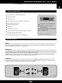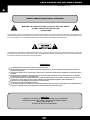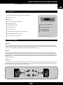
1
MT SERIES C
8001 C
ONE
MANUAL DEL USUARIO MT, MT S Y MT C SERIES
INTRODUCCION
ZKX audio ofrece la linea MT series totalmente renovada. Cambios en su estética, actualización técnica y mejoras en su aplicación hacen de esta
linea un producto optimo para su uso. Los equipos tienen un diseño sobredimensionado que permite usarlas en las condiciones más desfavorables,
atendiendo a las distintas condiciones de temperatura que posee nuestro país. La MT series le asegura una amplia gama de aplicaciones que van
desde la sonorización de pequeños ambientes hasta armados de sistemas de PA, Sonidistas, dj's cuentan con la posibilidad de tener amplificadores
totalmente nacionales con un servicio de postventa único, con soluciones rápidas y seguras como ningún producto foráneo puede garantizar.
Gracias por elegirnos, hoy, siendo una empresa joven, representamos una buena parte del mercado de unidades de potencias que se utilizan en
Argentina.
Para obtener el mejor funcionamiento de su MT o MTs, por favor lea este MANUAL PARA EL USUARIO atentamente y téngalo para futuras
referencias. Si usted ignora el manual y salta directamente a lo desconocido, algo puede pasar que cause daños a la unidad o no la deje funcionar
apropiadamente. Mantenga limpia ésta unidad, utilizando un cepillo seco y suave, ocasionalmente frótela con una franela húmeda. No utilice ningún
tipo de solvente, que puede dañar la pintura o las piezas de plástico. El cuidado y la inspección regulares serán compensados por una vida útil larga y
una confiabilidad máxima.
Esta unidad fue cuidadosamente empaquetada en el sitio de fabricación y la caja fue diseñada para proteger la unidad de manejos bruscos. Nosotros
le recomendamos que examine cuidadosamente su paquete y su contenido y ver si se encuentra alguna señal de daño físico, que puede haber
ocurrido durante el transporte.
Si la unidad se encuentra dañada: notifiquelo inmediatamente a su vendedor y a la empresa de distribución. Los reclamos por daños o reposiciones
pueden no ser concedidos si usted los ha reportado inapropiadamente o en una manera no oportuna.
ZKX audio
Miguel Cane 1795
(B1607AQW) Villa Adelina, Provincia de Buenos Aires
Argentina
Tel /Fax: (54 + 11) 4765-7777 / 4763-3262
DIPS
(((CLASS)))
AB
MOSFET
TECHNOLOGY
Digital Intelligent
Protection System
CLIP
] ]
Ventas: [email protected]
Depto. Técnico: [email protected]
Site: http://www.zkxargentina.com.ar
BRIDGE
M O D E
L I M I T E R
AIRCOOLER
MANUAL DEL USUARIO MT, MT S Y MT C SERIES
#1
ADVERTENCIA DE SEGURIDAD COMUN A TODAS LAS POTENCIAS
ADVERTENCIA PARA REDUCIR EL RIESGO DE FUEGO O SHOCK
ELECTRICO, NO EXPONGA ESTA UNIDAD A LA LLUVIA O HUMEDAD
No permita que entre agua o algún tipo de liquido a la unidad. Si ésta a sido expuesta a lluvia o líquidos, por favor, desenchufe inmediatamente el cable de la
energía desde la salida (con LAS MANOS SECAS) y llame a un servicio técnico calificado para chequear la unidad. Mantenga esta unidad alejada de
fuentes de calor com radiadores, registradores de calor, estufas, etc. Esta unidad contiene piezas que no pueden ser reparadas por el usuario. Consulte
con todo tipo de servicio que necesite a un ingeniero calificado a través de su vendedor ZKX.
El triángulo con una flecha que se asemeja a un rayo que se encuentra en su componente lo alerta de la presencia de “voltaje peligroso” sin aislar dentro del
cercamiento que puede ser suficiente para constituir en un riesgo de shock. El triángulo con un signo de exclamación le recuerda que es importante la
lectura de las instrucciones de reparación y mantenimiento que está en este presente manual.
¡ADVERTENCIAS!
El equipo debe ubicarse cerca de un tomacorriente y este debe ser fácilmente accesible.
El equipo no debe exponerse al goteo o salpicaduras y no deben colocarse objetos llenos de líquido, tales como jarrones, vasos, etc.
Si el cable de alimentación se encuentra dañado, no utilice el producto. En este caso el cable debe ser reemplazado por el fabricante
o por el personal técnico autorizado.
No exponga la unidad a fuentes de llama o calor intenso. No apoye sobre ella velas encendidas ni objetos similares. No deje el
aparato al alcance de la luz solar directa.
Ubique el aparato en un lugar con adecuada ventilación. No lo apoye sobre alfombras, sillones ni otras superficies blandas o
irregulares. No tape las rendijas de ventilación: no apoye sobre la unidad periódicos, carpetas, manteles, etc.
Asegure una buena estabilidad del aparato. Evite ubicarlo sobre superficies inclinadas.
No lo exponga a golpes ni vibraciones mecánicas.
No cambie la ficha de alimentación ni utilice adaptadores. Si su instalación domiciliaria no posee tomacorrientes compatibles con la
ficha, acuda a un electricista matriculado para que realice los cambios necesarios en su instalación eléctrica.
PRECAUCION
PARA REDUCIR EL RIESGO DE SHOCK ELECTRICO, NO REMUEVA
LAS COBERTURAS (O EL RESPALDO). NO HAY PIEZAS
REPARABLES POR EL USUARIO DENTRO DE LA UNIDAD.
CONSULTE TODO TIPO DE SERVICIO A UN PERSONAL DE SERVICIO
CALIFICADO
- pagina 1 -
MANUAL DEL USUARIO MT, MT S Y MT C SERIES
#2
CARACTERISTICAS
Avanzado diseño con circuito de tercera generación.
Salida de alta corriente.
MT 2400
Limitador de entrada.
Estereo seleccionable, modos de amplificador: estereo / puente.
Controles de ganancia individuales.
*Nivel de entrada seleccionable 0dBu / 1,4V.
Refrigeración forzada por turbina.
*Refrigeración forzada por turbina con
Gabinete robusto.
control de temperatura.
*Llave de conmutación de entrada LINK / OFF.
Accesibilidad para rack de 19”.
*Llave GROUND - LIFT.
Sistema de limitación automática de rápida recuperación por clipping.
DIPS: Digital Intelligent Protection System.
* Solo para los modelos MT 2000 y MT 2400s.
Linkeo para posibilitar la conexión de otros amplificadores.
INSTALACION
ARMADO
El amplificador de potencia puede ser instalado en una unidad de rack de 19”. Requiere de 3 unidades (5.25 pulgadas) de altura y puede asegurarse
al rack con cuatro tornillos y arandelas. En un rack, es mejor armar las unidades, una sobre la otra, con al menos una unidad de espacio entre dos
amplificadores. Esto le brinda una ventilación y soporte eficientes.
REFRIGERACION
Antes de armar su amplificador, usted debe familiarizarse con los requerimientos para la refrigeración. El aire fluye desde atrás hacia adelante, por lo
que es importante no bloquear la parte frontal. Si el amplificador se monta a través de rack, los espacios abiertos en la parte frontal del rack deben ser
cubiertos para prevenir que el aire caliente sea devuelto a la ventilación de atrás hacia adelante.
Las restricciones de la ventilación son las causas más comunes de la refrigeración inadecuada. Esto puede ser resultado del armado inapropiado, de
conexiones deficientes, de polvo en los filtros y de las puertas cerradas en el rack. Arme el amplificador de manera tal que permita la salida de la
ventilación en la parte frontal para asegurar de que su amplificador funcione apropiadamente.
CONEXIONADO
El conexionado de las series MT, MTs y MTc hacia sus cajas acústicas, en el modo ESTEREO, debe realizarse de la siguiente manera: mueva la
llave que se encuentra en la parte trasera de su gabinete y colóquela en este modo. Conecte el positivo (+) y el negativo (-), que sale de cada caja
acústica, a cada respectivo canal (channel 1 y channel 2). Como se muestra en la figura 1.
CHANNEL 2
CHANNEL 1
figura 1.
- pagina 2 -
MANUAL DEL USUARIO MT, MT S Y MT C SERIES
#3
Para el modo puente (BRIDGE), coloque la llave en esa posición, conecte solo a las borneras rojas de cada canal. Como se muestra en la figura 2.
NO UTILICE LAS BORNERAS NEGRAS PARA EL MODO BRIDGE CUANDO ESTE LA LLAVE EN ESTE MISMO.
CONEXIONADO MODO BRIDGE
CHANNEL 2
CHANNEL 1
figura 2.
DESCRIPCION DEL PANEL FRONTAL
1 - CONTROL DE GANANCIA
Estas dos perillas son controles de nivel para cada canal del amplificador. La ganancia aumenta cuando se gira la perilla en sentido horario. Esta
unidad se caracteriza por tener controles de ganancia.
2 - FUNCIONAMIENTO DEL SISTEMA DIPS
Al encender la unidad de potencia se pone en funcionamiento el sistema de protección DIPS. El LED rojo (DIPS) ubicado en el frente, destellará tres
veces en intervalos de un segundo de duración, indicando el retardo de la línea de parlantes. A continuación se encenderá el LED (OP) indicando que
la unidad está en correcto funcionamiento.
IMPORTANTE: Si después de haber encendido el LED (OP) o antes de esto, el LED (DIPS) encendiera en forma permanente, nos indicará que el
equipo presenta alguna anomalía en las líneas del sistema acústico (corto-circuito de salida). No se alarme sus parlantes no corren riesgos.
Si la anomalía fuese momentánea, el sistema DIPS verificara la salida durante una fracción de segundo y restaurará la misma por sí solo e indicara el
funcionamiento correcto LED (OP). Si esto no sucediera revise las líneas de salida y corrija el problema restaurando el aislamiento donde fuera
necesario. Tenga en cuenta que el sistema DIPS le permitirá hasta cinco oportunidades de corrección del desperfecto sin tener que apagar la unidad,
después de la quinta detección de error, el LED (DIPS) encenderá en forma intermitente bloqueando la unidad hasta que se solucione el
inconveniente.
Para resetear el sistema, solo apague la unidad y vuelva a encenderla luego de unos segundos. En caso de que al encender la unidad el LED rojo
(DIPS) quedase encendido en forma permanente por favor consulte con nuestro departamento técnico.
3 - LED DE OPERACION (OP)
Cada canal del amplificador de potencia posee un LED (OP) que indica el modo de operación del sistema ( verde modo estereo o ambar modo
puente) para línea MT. Para la serie MTs el LED (OP) modo de operación del sistema será azul y en el sistema bridge se apaga el LED (OP) del
CH 2.
4 - INTERRUPTOR DE ENERGIA
Aunque la serie MT o MTs de la serie de amplificadores ZKX tenga un circuito de retardo de encendido, una buena practica, es reducir ambos
controles de ganancia, antes de encender el amplificador. El procedimiento de encendido para un sistema de audio debe empezar desde los
instrumentos seguida por la mezcladora y usted debe verificar si todas las operaciones del sistema están normales antes de encender el amplificador.
MT 2400
* Este gráfico sirve de referencia para toda la linea de amplificadores MT, MTs y MTc.
- pagina 3 -
1
CONTROL DE GANANCIA
2
DIPS (Digital Intelligent Protection System)
3
LED DE SEÑAL (OP)
4
INTERRUPTOR DE ENERGIA
MANUAL DEL USUARIO MT, MT S Y MT C SERIES
#4
DESCRIPCION DEL PANEL TRASERO
1
ALIMENTACION
2
FUSIBLE
3
CONECTORES DE SALIDA
4
TURBINA
5
CONECTORES DE ENTRADA
6.1 LLAVE ESTEREO / BRIDGE
6.2 LLAVE GROUND / LIFT
* Gráfico solo valido para los modelos MT 250, 500, 1000, 1500, MTs 700, 1400 y MTc 8001.
1 - ALIMENTACION
Todas las unidades están armadas con un enchufe apropiado con el cable para el voltaje AC requerido. Este producto esta equipado con un enchufe
con toma a tierra. Esto es para su seguridad y no debe ser eliminado. Verifique el voltaje AC antes de conectar el enchufe.
2 - FUSIBLE
Se provee en fusible para proteger la fuente de alimentación de excesiva corriente. Se ubica en la parte trasera del panel al lado de la alimentación.
3 - CONECTORES DE SALIDA:
OUTPUT: Se provee de un par de borneras para la conexión de salida de cada canal. Los altoparlantes pueden ser fácilmente conectados,
mediante el uso de enchufes banana spade plugs o cables desnudos. Los spade plugs y los cables desnudos deben ser ambos atornillados,
firmemente para evitar un cortocircuito.
LINK: Se provee de 2 (dos) conectores XLR 3 pins, para posibilitar la conexión a otra potencia.
4 - TURBINA
Esta turbina asegura la temperatura adecuada en el interior del equipo. Mantenga las ventilaciones frontal y trasera limpias para permitir un fluido
completo. el aire caliente sale por el frente del amplificador, por lo que no calienta el interior del rack. Asegurese que el aire fresco pueda entrar al
rack.
5 - CONECTORES DE ENTRADA (INPUT)
El amplificador ofrece los conectores Neutrik Combo, plug 6,5 XLR 3 pins.
6.1 - LLAVE ESTEREO / BRIDGE
Apague el equipo antes de cambiar el modo de operación. En la operación estereo, cada canal del amplificador funciona independientemente de su
propia señal y de los parlantes. En la operación PUENTE, ambos canales pueden ser configurados para manejar una carga única al doble de energía.
Utilice el siguiente procedimiento de seguridad cuando cambie de modo estereo a puente:
6.2 - LLAVE GROUND / LIFT
Esta llave permite la variación de conexión de tierra del equipo.
GROUND: Conexión directa a chasis.
LIFT: Conexión aislada de chasis.
ATENCION
AA)
APAGUE EL AMPLIFICADOR.
BB)
PARA LA SERIE MT COLOQUE UN PARLANTE DE NO MENOS DE OCHO OHMS DE IMPEDANCIA,
EN LOS TERMINALES DE SALIDA ROJA (+) DEL AMPLIFICADOR. EN LA SERIE MTs COLOQUE UN
PARLANTE DE NO MENOS DE CUATRO OHMS DE IMPEDANCIA, EN LOS TERMINALES DE SALIDA
ROJA (+) DEL AMPLIFICADOR
CC)
ASEGURESE DE QUE ALLA SOLO UNA SEÑAL DE ENTRADA CONECTADA AL CH 1.
DD)
COLOQUE EL AMPLIFICADOR EN MODO PUENTE (BRIDGE).
EE)
GIRE LOS CONTROLES GAIN DE CH 1 Y CH 2 AL EXTREMO IZQUIERDO Y LUEGO ENCIENDA EL
AMPLIFICADOR.
FF)
EL CONTROL DE GANANCIA SE EFECTUARA MEDIANTE CH 1.
- pagina 4 -
MANUAL DEL USUARIO MT, MT S Y MT C SERIES
#5
1
ALIMENTACION
2
FUSIBLE
3
CONECTORES DE SALIDA
4
TURBINA
5
CONECTORES DE ENTRADA
6
LLAVE ESTEREO / BRIDGE
LLAVE GROUND / LIFT
LLAVE 1.4V / 0dBu
LLAVE LINK / OFF
* Gráfico solo valido para los modelos MT 2000 y MTs 2400.
6 - LLAVE ESTEREO / BRIDGE
Apague el equipo antes de cambiar el modo de operación. En la operación estereo, cada canal del amplificador funciona independientemente de su
propia señal y de los parlantes. En la operación PUENTE, ambos canales pueden ser configurados para manejar una carga única al doble de energía.
Utilice el siguiente procedimiento de seguridad cuando cambie de modo estereo a puente:
6 - LLAVE GROUND / LIFT
Esta llave permite la variación de conexión de tierra del equipo.
GROUND: Conexión directa a chasis.
LIFT: Conexión aislada de chasis.
6 - LLAVE 1.4 V / 0dBu
Mediante esta llave usted podrá seleccionar la sensibilidad de su equipo a 0dBu ( sistemas no balanceados), o 1.4 Volt ( sistemas balanceados).
6 - LLAVE LINK / OFF
Por medio de esta llave, usted podrá conectar varios equipos en paralelo, utilizando cualquiera de los dos conectores ( INPUT) como entrada de
señal y el restante como salida hacia otro amplificador.
REFERENCIAS DE MEDIDAS Y PESOS
MODELOS
250, 500, 1000, 1500, 700, 1400, 8001.
MT 1500
Ancho: 485 mm
Alto: 129 mm
Profundidad: 375 mm
Pesos
MT 250: 9.6 Kg
MT 500:13.1 Kg
MT 1000: 14.9 Kg
MT 1500: 18 Kg
MTs 700: 16.6 Kg
MTs 1400: 17.8 Kg
MTc 8001: 16.6 Kg
MODELOS
2000, 2400.
MT 2400
Ancho: 485 mm
Alto: 129 mm
Profundidad: 555 mm
Pesos
MT 2000: 30 Kg
MT 2400: 28 Kg
- pagina 5 -
- pagina 6 -
1800 W
500 W
960 W
2000
>500 @ 8 ohms
PESO
DIMENSIONES
9.6 Kg
13.1 Kg
220V 50Hz 4A
14.9 Kg
485 x 129 x 375
220V 50Hz 6A
18 Kg
220V 50Hz 8A
30 Kg
485 x 129 x 555
220V 50Hz 15A
900 W
1400 W
280 W
500 W
690 W
1400
16.6 Kg
17.8 Kg
485 x 129 x 375
220V 50Hz 10A
desbalanceada 10K ohms
220V 50Hz 6A
mejor que 100 dB
< 0,1% a 10% del clipping
balanceada
20K ohms
ALIMENTACION
550 W
700 W
185 W
290 W
360 W
700
20Hz a 20.000Hz + / - 0.2 dB
1500 W
375 W
750 W
1500
desbalanceada 10K ohms
1000 W
270 W
480 W
1000
IMPEDANCIA DE ENTRADA
500 W
175 W
260 W
500
0 dBu
220V 50Hz 3A
250 W
90 W
130 W
250
Máxima potencia @ 8 ohms
SENSIBILIDAD
Entre 10Hz / 400Hz
AMORTIGUAMIENTO
Entre 20Hz y 20Khz
RELACION SEÑAL / RUIDO
Medida 1Khz
DISTORSION ARMONICA TOTAL
- 10 dB potencia máxima
RESPUESTA EN Hz
bridge mono
8 ohms
4 ohms
2 ohms
8 ohms x canal
4 ohms x canal
2 ohms x canal
1 ohms x canal
POTENCIA DE SALIDA
MODELOS
ESPECIFICACIONES TECNICAS POR MODELOS
28 Kg
485 x 129 x 555
220V 50Hz 15A
balanceada
20K ohms
1600 W
2100 W
430 W
840 W
1100 W
2400
16.6 Kg
485 x 129 x 555
220V 50Hz 5A
desbalanceada
10K ohms
240 W
385 W
490 W
60 W
125 W
199 W
255 W
8001
MANUAL DEL USUARIO MT, MT S Y MT C SERIES
#6
User`s
Manual
ENGLISH
USER`S MANUAL MT, MTs and MTc SERIES
#8
INTRODUCTION
ZKX audio offers a brand new MT line series. A whole different image and technicians updates for you to get a better product. An over the line design
that allowed you to work even in the worst conditions of the different temperatures for the different places of the country. The MT series provides a
variety of appliances going from the very small studio to PA systems. Dj s and sound workers are able to own a national amplifier with an unique up
sale service, fast and safe solutions delivery like no other foreign equipment would ever give.
Thank you for choosing us today, when we still young but growing because of you. We are one of the biggest amplifiers trades in the market in
Argentina so far.
Keep this unit clean by using a soft dry brush and occasionally wiping it with a damp cloth. Do not use any others solvents, which may damage the
paint or plastic parts. Regular care and inspection will be rewarded by a long life product and maximun reliability.
This unit was carefully packed at the manufacturing site and the packaging box was designed to protect the unit from rough handling. We recommend
that you carefully examine the packaging and its contents for any signs of physical damage which may have occurred during transportation.
If the unit is damaged: notify your dealer and the shipping company immediately. Claims for damage or replacement may not be granted if not reported
properly or in a timely manner.
ZKX audio
Miguel Cane 1795
(B1607AQW) Villa Adelina, Province of Buenos Aires
Argentina
Phone /Fax: (54 + 11) 4765-7777 / 4763-3262
DIPS
(((CLASS)))
AB
MOSFET
TECHNOLOGY
Digital Intelligent
Protection System
- page 8 -
CLIP
] ]
Sales: [email protected]
Technical Department: [email protected]
Site: http://www.zkxargentina.com.ar
BRIDGE
M O D E
L I M I T E R
AIRCOOLER
USER`S MANUAL MT, MTs and MTc SERIES
#9
SAFETY PRECAUTIONS FOR ALL VOLTAGES!
WARNING- TO REDUCE THE RISK OF FIRE OR ELECTRIC SHOCK,
DO NOT EXPOSE THIS UNIT TO RAIN
OR MOISTURE
Do not allow water or liquids to be spilled into this unit. If the unit has been exposed to rain or liquids, please unplug the power cord immediately from the
outlet (with DRY HANDS) and get a qualified service technician to check it. Keep this unit away from heat sources such as radiators, heat registers, stoves,
etc. This unit contains no user – serviceable parts. Refer all service needs to qualified service engineer through a ZKX dealer.
This triangle with an arrow similar to a flash of lightning that appears on your component alerts you to the presence of uninsulated “dangerous voltage” inside
the enclosure that may be sufficient to constitute a risk or shock. The triangle with an exclamation mark was designed to point out the need to read carefully
the repair and maintenance instructions in this accompanying literature.
¡WARNINGS!
The equipment must be located near an easily accessible power outlet.
The equipment does not have to be exposed to dripping or splashes and do not place objects filled with liquid, such as vases or
glasses, on the apparatus.
If the feeder is damaged, do not use the product. In this case the cable must be replaced by the manufacturer or authorized technical
personnel.
Do not expose the unit to flame or intense heat sources. Do not place lighted candles or any other similar objects on the apparatus,
which must not be reached by direct sunlight either.
Do not install the appliance in a confined space since it needs a suitable ventilation. Do not place it on carpets, armchairs, as well as
on other soft or uneven surface. Do not cover the ventilation of the apparatus with newspapers, folders, tablecloths, etc.
Make sure it has a good stability. Avoid placing it on an inclined surface.
Do not expose it to mechanical vibrations or blows
Do not change the plug or use adapters. If your residential installation does not have power outlets which can be compatible with the
plug, go to a registered electrician who will make the necessary changes in your electrical sytem.
CAUTION
TO REDUCE THE RISK OF ELECTRIC SHOCK, DO NOT REMOVE
COVER (OR BACK). NO USER –SERVICEABLE PARTS INSIDE.
REFER SERVICING TO
QUALIFIED SERVICE PERSONNEL.
- page 9 -
USER`S MANUAL MT, MTs and MTc SERIES
#10
FEATURES
Advanced powerful perfomance – third generation circuit design.
Output of high current.
MT 2400
Input limiter.
Selective stereo, bridge mono amp modes.
Independent gain controls.
*Selective level input 0dBu / 1,4V.
Cooling reinforced by turbine.
*Cooling with temperature control.
Very rugged housing.
*Input switch LINK / OFF.
Fits a standard 19¨ rack”.
*Switch GROUND - LIFT.
Automatic limitation system of rapid recovery by clipping.
DIPS: Digital Intelligent Protection System.
LINK: enable to link to other amplifiers.
* Only for MT 2000 and MT 2400s series.
INSTALLATION
MOUNTING
The power amplifier can be installed in a standard 19 inch equipment. It requires 3 units (5.25 inches) for the MT series of vertical rack space and
secures to the rack cabinet with four rack mount screws and cup washers. Inside every rack, it is best to mount the units one above the other, leaving
at least a unit of space between two amplifiers. This will provide for efficient airflow and support.
COOLING
Before mounting your amplifier, you should become familiar with its cooling requirements. The air flows from back to front, so it is important not to
block its frontal part. If the amplifier is rack – mounted, the open spaces on the front of the rack should be covered to prevent heated air being drawn
back into the back - to - front airflow. Airflow restrictions are the most common cause of inadequate cooling. They may result from improper mounting,
bundles of power cords, clogged dust filters and closed rack doors. Mount the amplifier to allow sufficient airflow out of the front outlets to ensure your
amplifier works properly.
CONNECTION
The connection of the series MT, MTs and MTc with their acoustic boxes, in the STEREO mode, must be accomplished in the following way: move the
switch on the rear part of your cabinet and put it on STEREO. Connect the positive (+) and the negative (-) wires coming out of each acoustic box to
each respective channel (channel I and channel II) as shown in figure 1.
CHANNEL 2
CHANNEL 1
figure 1.
- page 10 -
USER`S MANUAL MT, MTs and MTc SERIES
#11
For the BRIDGE mode put the switch on that position and connect only to each channel red knobs. As shown in figure 2. DO NOT USE THE BLACK
KNOBS FOR THE BRIDGE MODE WHEN THE SWITCH IS ALREADY ON THIS MODE.
CONECTION MODE BRIDGE
CHANNEL 2
CHANNEL 1
figure 2.
FRONT PANEL DESCRIPTION
1 - GAIN CONTROL
These two knobs control the level of each channel of the amplifier. Gain increases will result when the knob is turned in hourly sense. This unit is
characterized by having gain controls.
2 - OPERATION OF THE DIPS SYSTEM
When the power unit is turned on, the DIPS protection system activates.The red LED (DIPS) located in the front, will flash three times for a second to
show the delay of the loudspeakers. Then the LED (OP) will switch on indicating that the unit is already in operation.
IMPORTANT: If after having lit up the LED (OP) or before this, the LED (DIPS) would remain on, it will indicate that the system presents some
malfunctioning in the lines of the acoustic system (short-circuit in the exit). If such is the case, do not worry your speakers will not be at risk.
If the anomaly were temporary the DIPS system will verify the exit in the fraction of a second and will be able to restore itself indicating correct
operation LED (OP).
If this did not happen check the lines of exit and repair the problem insulating wherever necessary. Take into account that the DIPS system will give
you up to five opportunities to correct the malfunctioning without turning it off. However, after the fifth signal of error detection, the LED (DIPS) will keep
flashing, blocking the unit until the drawback is solved. In order to re-start the system, turn off the unit to turn it on again just after few seconds.
3 - OPERATION LED (OP))
Each channel of the amplifier has a LED (OP) that indicates the system operation mode (Green, stereo mode/ Amber, bridge mode).
4 - POWER SWITCH
Though the series MT or MTs of amplifiers ZKX has a circuit with delayed ignition,a good practice is to reduce both gain controls before switching on
the amplifier.
The ignition procedure for an audio system must start from the instruments, followed by the blender and you must verify if all the system of operation is
normal before lighting up the amplifier.
MT 2400
* Only reference for all power amplifiers MT, Mts and MTc series.
- page 11 -
1
GAIN CONTROL
2
DIPS (Digital Intelligent Protection System)
3
OPERATION LED (OP)
4
POWER SWITCH
USER`S MANUAL MT, MTs and MTc SERIES
#12
REAR PANEL DESCRIPTION
1
POWER SUPPLY
2
FUSE
3
OUTPUT CONNECTORS
4
FAN COOLER
5
INPUT CONNECTORS
6.1 SWITCH STEREO / BRIDGE
6.2 SWITCH GROUND / LIFT
* Only models MT 250, 500, 1000, 1500, MTs 700, 1400 and MTc 8001.
1 - POWER CORD
All the units are provided with an appropriate plug and cable according to the AC required voltage. This product is equipped with a ground plug which
must not be removed for safety reasons. Please check AC voltage before connecting the plug.
2 - FUSE
It is provided with a fuse to protect the power supply from excessive current. It is located in the rear part of the panel next to the power cord.
3 - OUTPUT CONNECTORS
It is provided with a pair of posts for the exit connection to each channel. The speakers can be easily connected using banana, spade or nude cables.
The spade plugs and the nude ones should be both firmly screwed to avoid a short circuit.
4 - FAN
This turbine insures adequate temperature inside the equipment. Keep the frontal and rear ventilations clean to allow a complete airflow. Hot air will
pass through the front of the amplifier, so as not to heat the interior of the rack. Make sure of the fact that fresh air must enter fully into the rack.
5 - INPUT CONNECTORS
The entry amplifier offers the entry connectors Neutrik Combo, 6,5 XLR 3 pins.
6.1 - SWITCH STEREO / BRIDGE
Turn off energy before changing the operation manner. In the Stereo operation , each channel of the amplifier operates independently from their own
signal and speakers. In the bridge operation, both channels can be configured to handle a singular load with double energy. Use the following safety
procedure when pressing stereo or bridge mode.
6.2 - SWITCH GROUND / LIFT
This switch acts the as to connect the mass of signal entrance to chassis ( GROUND) or to leave it floating way ( LIFT).
CAUTION
AA)
·TURN OFF THE AMPLIFIER.
BB)
·FOR THE MT SERIES CHOOSE A SPEAKER OF NO LESS THAN 8 OHMS OF IMPEDANCE,
IN THE RED EXIT TERMINALS (+) OF THE AMPLIFIER. FOR THE MTS SERIES SELECT A
SPEAKER OF NO LESS THAN 4 OHMS OF IMPEDANCE, IN THE RED EXIT TERMINALS OF
THE AMPLIFIER.
CC)
MAKE SURE THAT THERE EXISTS ONLY ONE ENTRY SIGNAL CONNECTED TO THE CH1.
DD)
PUT THE AMPLIFIER ON BRIDGE MODE.
EE)
TURN THE GAIN CONTROLS OF CH1 AND CH2 TO THE LEFT EXTREME AND THEN LIGHT
THE AMPLIFIER.
FF)
GAIN CONTROL WILL BE PRODUCED BY CH1.
- page 12 -
USER`S MANUAL MT, MTs and MTc SERIES
#13
1
POWER SUPPLY
2
FUSE
3
OUTPUT CONNECTORS
4
FAN COOLER
5
INPUT CONNECTORS
6
SWITCH STEREO / BRIDGE
SWITCH 1.4V / 0dBu
SWITCH GROUND / LIFT
SWITCH LINK / OFF
* Gráfico solo valido para los modelos MT 2000 y MTs 2400.
6 - SWITCH STEREO / BRIDGE
Turn off energy before changing the operation manner. In the Stereo operation , each channel of the amplifier operates independently from their own
signal and speakers. In the bridge operation, both channels can be configured to handle a singular load with double energy. Use the following safety
procedure when pressing stereo or bridge mode.
6 - SWITCH 1.4 V / 0dBu
By means of this switch you will be able to select the sensitivity of your amplifier 0dBu ( systems unbalanced) or 1,4 Volt ( balanced systems).
6 - SWITCH GROUND / LIFT
This switch acts the as to connect the mass of signal entrance to chassis ( GROUND) or to leave it floating way ( LIFT).
6 - SWITCH LINK / OFF
By means of this switch you will be ableto connect several equipment in parallel, using anyone of the two connectors ( INPUT) like signal
entrance and the rest like exit to another amplifier.
MEASURE AND WEIGHT REFERENCE
MODELS
250, 500, 1000, 1500, 700, 1400 and 8001.
MT 1500
Width: 485 mm
Height: 129 mm
Depth: 375 mm
Weight
MT 250: 9.6 Kg
MT 500:13.1 Kg
MT 1000: 14.9 Kg
MT 1500: 18 Kg
MTs 700: 16.6 Kg
MTs 1400: 17.8 Kg
MTc 8001: 16.6 Kg
MODELS
2000, 2400.
MT 2400
Width: 485 mm
Height: 129 mm
Depth: 555 mm
Weight
MT 2000: 30 Kg
MT 2400: 28 Kg
- page 13 -
- page 14 -
WEIGHT
DIMENSIONS
POWER SUPPLY
INPUT IMPEDANCE
Full rated power @ 8 ohms
INPUT SENSIVITY
Between 10Hz / 400Hz
DAMPING
Between 20Hz and 20Khz
RELATION SIGNAL / NOISE
Measure 1Khz
THD (TOTAL HARMONIC DISTORTION)
- 10 dB below rated power
FREQUENCY RESPONSE
bridge mono
8 ohms
4 ohms
2 ohms
8 ohms per channel
4 ohms per channel
2 ohms per channel
1 ohms per channel
OUTPUT POWER
MODELS
9.6 Kg
220V 50Hz 3A
250 W
90 W
130 W
250
13.1 Kg
1000 W
270 W
480 W
1000
14.9 Kg
485 x 129 x 375
220V 50Hz 6A
unbalanced 10K ohms
220V 50Hz 4A
500 W
175 W
260 W
500
TECHNICAL SPECIFICATIONS BY MODELS
550 W
700 W
185 W
290 W
360 W
700
30 Kg
485 x 129 x 555
220V 50Hz 15A
balanced
20K ohms
0 dBu
>500 @ 8 ohms
900 W
1400 W
280 W
500 W
690 W
1400
16.6 Kg
17.8 Kg
485 x 129 x 375
220V 50Hz 10A
unbalanced 10K ohms
220V 50Hz 6A
better than 100 dB
< 0,1% to 10% del clipping
220V 50Hz 8A
18 Kg
1800 W
500 W
960 W
2000
20Hz to 20.000Hz + / - 0.2 dB
1500 W
375 W
750 W
1500
28 Kg
485 x 129 x 555
220V 50Hz 15A
balanced
20K ohms
1600 W
2100 W
430 W
840 W
1100 W
2400
16.6 Kg
485 x 129 x 555
220V 50Hz 5A
unbalanced
10K ohms
240 W
385 W
490 W
60 W
125 W
199 W
255 W
8001
USER`S MANUAL MT and MTs SERIES
#14
USER`S MANUAL MT and MTs SERIES
#15
NOTAS:
- page 15 -
9