1
Installation Manual
IM 1029-2
Group: Chiller
Part Number: 331374611
Effective: October 2012
Supersedes: May 2012
Magnitude™ Magnetic Bearing Centrifugal Chillers
Model WMC-145SBS to 400DBS
HFC-134a
50/60 Hertz
00
Table of Contents
Nomenclature ................................................. 3
Electrical Data ............................................. 31
VFD Line Harmonics ................................... 42
Fuses ............................................................ 43
Installation ............................................. 4
System Pumps ..................................... 43
Introduction ........................................... 3
Receiving and Handling ................................. 4
Multiple Chiller Setup ........................ 44
Location and Mounting ........................ 5
Prestart System Checklist .................. 46
Water Piping ................................................... 5
Field Insulation............................................... 8
Long Term Storage ............................. 47
Physical Data and Weights ................... 9
Operation............................................. 48
Chiller Dimensions .............................. 11
Operator Responsibilities ............................. 48
Compressor Operation ................................. 48
MicroTech II Control ................................... 49
Use with On-Site Generators ....................... 49
Building Automation Systems ...................... 50
Harmonic Filter Dimensions ........................ 17
Relief Valves ......................................... 21
Electrical Information ........................ 23
Power Wiring ............................................... 23
Optional Harmonic Filter ............................. 30
*
Applies to 60 Hz Units
Applies to 60 Hz Units
*Unit Controllers are LonMark certified with an optional LonWorks communication module.
Manufactured in an ISO Certified Facility
©2012 McQuay International. Illustrations and data cover the McQuay International product at the time of publication and we reserve
the right to make changes in design and construction at anytime without notice.
™® The following are trademarks or registered trademarks of their respective companies: BACnet from ASHRAE; LONMARK, LonTalk,
LONW ORKS, and the LONMARK logo are managed, granted and used by LONMARK International under a license granted by Echelon
Corporation; Modbus from Schneider Electric; MicroTech II, and Open Choices from McQuay International.
2
Magnitude™ Frictionless Centrifugal Chillers – Model WMC
IM 1029-2
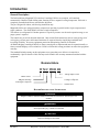
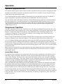
Introduction
General Description
The Daikin McQuay Magnitude™ Frictionless Centrifugal Chillers are complete, self-contained,
automatically controlled, fluid-chilling units featuring oil-free, magnetic bearing compressors. Each unit is
completely assembled and factory tested before shipment.
They are designed for indoor, non-freezing installation only.
Magnitude chillers are equipped with two compressors operating in parallel with a single evaporator and
single condenser. The model WMC 145S has a single compressor.
The chillers use refrigerant R-134a that operates at a positive pressure over the entire operation range, so no
purge system is required.
The controls are pre-wired, adjusted and tested. Only normal field connections such as water piping, relief
valve piping, electric power and control interlocks are required, thereby simplifying installation and
increasing reliability. Necessary equipment protection and operating controls are included.
All Daikin McQuay centrifugal chillers are factory-tested prior to shipment and must be commissioned by a
factory-trained McQuay service technician. Failure to follow this startup procedure can affect the equipment
warranty.
The standard limited warranty on this equipment covers parts that prove defective in material or
workmanship. Specific details of this warranty can be found in the warranty statement furnished with the
equipment.
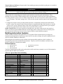
Nomenclature
W M C 290 D BS
Vintage/Single Circuit.
Water-cooled
D=Dual Compressors
S=Single Compressor
Magnetic Bearings
Centrifugal Compressor
Nominal Tons
HAZARD IDENTIFICATION INFORMATION
!
DANGER
Dangers indicate a hazardous situation which will result in death or serious injury if not
avoided.
!
WARNING
Warnings indicate potentially hazardous situations, which can result in property damage,
severe personal injury, or death if not avoided.
!
CAUTION
Cautions indicate potentially hazardous situations, which can result in personal injury or
equipment damage if not avoided.
IM 1029-2
Magnitude™ Frictionless Centrifugal Chillers – Model WMC
3
Installation
Receiving and Handling
The unit should be inspected immediately after receipt for possible damage.
All Daikin McQuay centrifugal water chillers are shipped FOB factory and all claims for handling and
shipping damage are the responsibility of the consignee.
On units with factory-installed insulation, the insulation is removed from the vessel lifting hole (also used for
transportation tie-downs) locations and are shipped loose. They should be secured in place after the unit is
finally placed. Neoprene vibration pads are also shipped loose in a control panel.
If so equipped, leave the shipping skid in place until the unit is in its final position. This will aid in handling
the equipment.
Extreme care must be used when rigging the unit to prevent damage to the control panels and refrigerant
piping. See the certified dimension drawings included in the job submittal for the center of gravity of the unit.
If the drawings are not available, consult the local Daikin McQuay sales office for assistance.
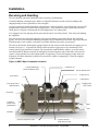
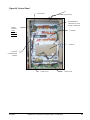
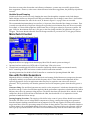
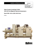
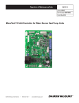
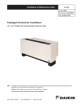
The unit can be lifted by fastening the rigging hooks to the four corners of the unit where the rigging eyes are
located (see Figure 1). A spreader bar must be used between the rigging lines to prevent damage to the
control panels, piping and electrical panels. The spreader-bar length should be equal to, or no more then 1foot shorter than the distance between the lifting holes located at opposite ends of the chiller. The unit will
require a single spreader-bar of this length capable of supporting 1.5 times the shipping weight of the unit.
Separately, all cables and hooks by themselves must also be capable of supporting 1.5 times the shipping
weight of the unit.
Figure 1, WMC, Major Component Locations
Combined Discharge
Check and Shutoff Valve
Compressor #1
Suction Shutoff Valve
Compressor #2
Power Panel
Control Panel
Evap. Relief Valve
(Behind Panel)
Rigging Holes
Each Corner
Evaporator
Condenser
Relief Valves
Behind Panel
Outlet
Inlet
Condenser
Electronic Expansion Valve
4
Operator Interface
Touch Screen, OITS
Magnitude™ Frictionless Centrifugal Chillers – Model WMC
IM 1029-2
Location and Mounting
Location
WMC chillers are intended only for installation in an indoor or weather protected area consistent with the
NEMA 1 rating on the chiller, controls, and electrical panels. Equipment room temperature for operating and
standby conditions is 40°F to 104°F (4.4°C to 40°C).
Clearance
The unit must be mounted on a level concrete or steel base and must be located to provide service clearance at
one end of the unit for possible removal of evaporator and/or condenser tubes. Evaporator and condenser
tubes are rolled into the tube sheets to permit replacement if necessary. The length of the vessel should be
allowed at one end. Doors or removable wall sections can be utilized. Clearance at all sides, including the
top, is 3 feet (1 meter). The U.S. National Electric Code (NEC) or local codes can require more clearance in
and around electrical components (4-feet in front of electrical panels) and must be checked for compliance.
They are designed for indoor, non-freezing installation suitable for NEMA 1 enclosures.
Vibration Pads
The shipped-loose neoprene vibration pads (shipped in the power panels) should be located under the corners
of the unit (unless the job specifications state otherwise). They are installed to be flush with the sides and
outside edge of the feet.
Insulation Corners
Insulation corners that cover the rigging holes on the upper corners of the vessel end plates are shipped loose
(in the power panels) and should be installed with adhesive after the init is set in place.
Mounting
Make sure that the floor or structural support is adequate to support the full operating weight of the complete
unit.
It is not necessary to bolt the unit to the mounting slab or framework; but should this be desirable, 1-1/8"
(28.5 mm) mounting holes are provided in the unit support at the four corners.
Note: Units are shipped with refrigerant valves closed to isolate the refrigerant in the unit
condenser. Valves must remain closed until start-up by the factory service technician.
Nameplates
There are several identification nameplates on the chiller:
•
The unit nameplate is located on the Unit Control Panel. It has a Model No. XXXX and Serial No.
XXXX. Both are unique to the unit and will identify it. These numbers should be used to identify the unit
for service, parts, or warranty questions. This plate also has the unit refrigerant charge.
•
Vessel nameplates are located on the evaporator and condenser. They have a National Board Number
(NB) and a serial number, either of which identify the vessel (but not the entire unit).
Water Piping
Vessel Drains at Start-up
The unit is tilted and drained of water in the factory and shipped with open drain valves in each head of the
evaporator and condenser. Be sure to close the valves prior to filling the vessel with fluid.
Evaporator and Condenser Water Piping
All vessels come standard with groove-type nozzles for Victaulic couplings (also suitable for welding), or
optional flange connections. The installing contractor must provide matching mechanical connections of the
size and type required. Victaulic connections are AWWA C-606 on 14-inch and larger sizes. Field supply
transitions if Victaulic brand AGS® (Advanced Groove System) type grooves are used on the field piping.
IM 1029-2
Magnitude™ Frictionless Centrifugal Chillers – Model WMC
5
!
CAUTION
Freeze Notice: Neither the evaporator nor the condenser is self-draining;
both must be blown out to help avoid damage from freezing temperatures.
The piping should include thermometers at the inlet and outlet connections and air vents at the high points.
The water heads can be interchanged (end for end) so that the water connections can be made at either end of
the unit. If this is done, use new head gaskets and relocate the control sensors.
In cases where the water pump noise can be objectionable, vibration isolation sections are recommended at
both the inlet and outlet of the pump. In most cases, it will not be necessary to provide vibration eliminator
sections in the condenser inlet and outlet water lines. But they can be required where noise and vibration are
critical.
Important Notes on Welding
If welding is to be performed on the mechanical or flange connections:
1. Remove the solid-state temperature sensor, thermostat bulbs and optional nozzle mounted flow switches (if
so equipped) from the wells to prevent damage to those components.
2. Properly ground the unit or severe damage to the MicroTech II® unit controller can occur.
Note: ASME certification will be revoked if welding is performed on a vessel shell or tube sheet.
Water pressure gauge connection taps and gauges must be provided in the field piping at the inlet and outlet
connections of both vessels for measuring the water pressure drop. The pressure drops and flow rates for the
various evaporators and condensers are job specific and the original job documentation can be consulted for
this information. Refer to the nameplate on the vessel shell for identification.
Connections
Be sure that water inlet and outlet connections match certified drawings and stenciled nozzle markings. The
condenser is connected with the coolest water entering at the bottom connection to maximize subcooling. The
evaporator outlet is on the right side of the head, regardless of which end the connections are on. Refer to
dimension drawings beginning on page 11.
!
CAUTION
When common piping is used for both building heating and cooling modes, care must be taken to
provide that water flowing through the evaporator cannot exceed 110°F. Water this hot can cause
the relief valve to discharge refrigerant or damage controls.
Piping must be supported to eliminate weight and strain on the fittings and connections. Chilled water piping
must be adequately insulated. Sufficient shutoff valves must be installed to permit draining the water from the
evaporator or condenser without draining the complete system and to allow vessel isolation.
Filtering and Treatment
Owners and operators must be aware that if the unit is operating with a cooling tower, cleaning and flushing
the cooling tower is required. Make sure tower blow-down or bleed-off is operating. Atmospheric air contains
many contaminants, which increases the need for water treatment. The use of untreated water will result in
corrosion, erosion, slime buildup, scaling, or algae formation. Water treatment service must be used. McQuay
International is not responsible for damage or faulty operation from untreated or improperly treated water.
Special care must be taken when utilizing open system water that is usually not treated (such as lakes, rivers,
and ponds). Special tube and water head material may be required to reduce damage from corrosion.
A cleanable 20-mesh water strainer must be installed in both vessels’ water inlet lines.
6
Magnitude™ Frictionless Centrifugal Chillers – Model WMC
IM 1029-2
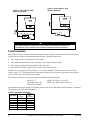
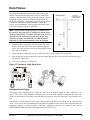
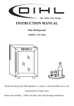
Flow Switch
Note: Chiller units must have flow switches for the evaporator and
condenser. McQuay International furnishes factory-installed and
wired, thermal-type flow switches as standard equipment on
Magnitude chillers. Field-installed and wired Delta-P switches can
be used instead.
They prevent the unit from starting without sufficient water flow
through the vessels. They also serve to shut down the unit in the
event that water flow is interrupted to guard against evaporator
freeze-up or excessive discharge pressure.
Figure 2, Unit-Mounted Flow Switch
Additionally, for a higher margin of protection, normally open
auxiliary contacts in the pump starters can be wired in series with
the flow switches as shown in the Field Wiring Diagram on page 40.
Cooling Towers
The condenser water flow rate must be checked to be sure that it conforms to the system design. A tower
bypass valve, controlled by the unit controller, is required to control the minimum condenser entering
temperature. Unless the system and chiller unit are specifically designed for them, condenser bypass or
variable condenser flow is not recommended, since low condenser flow rates can cause unstable operation and
excessive tube fouling.
Cooling towers used with Daikin McQuay centrifugal chillers are normally selected for condenser water inlet
water temperatures between 75°F and 90°F (24°C and 32°C). Lower entering water temperatures are
desirable from the standpoint of energy reduction, but a minimum does exist.
Condenser Water Temperature
When the ambient wet bulb temperature is lower than design, the entering condenser water temperature can be
allowed to fall, improving chiller performance.
Daikin McQuay chillers will start with entering condenser water temperature as low as 55°F (12.8°C)
providing the chilled water temperature is below the condenser water temperature.
Depending on local climatic conditions, using the lowest possible entering condenser water temperature can
be more costly in total system power consumed than the expected savings in chiller power would suggest due
to the excessive fan power required.
To obtain lower than 55°F (12.8°C) entering condenser water temperature with a tower selected to produce
85°F (29.4°C) water temperature at design ambient air temperatures, cooling tower fans must continue to
operate at 100% capacity at low wet bulb temperatures. As chillers are selected for lower kW per ton, the
cooling tower fan motor power becomes a higher percentage of the peak load chiller power. The offsets of
compressor power and fan power must be examined. On the other hand, the low condenser water
temperatures can be easy and economical to achieve in mild climates with low wet bulb temperatures.
Even with tower fan control, some form of water flow control such as tower bypass must be used and
controlled by the chiller MicroTech II controller.
Figure 3 and Figure 4 illustrate two temperature-actuated tower bypass arrangements. The “Cold Weather”
scheme, Figure 4, provides better startup under cold ambient air temperature conditions since most of the
piping is indoors and not subjected to cold ambient air. The check valve may be required to prevent air at the
pump inlet.
IM 1029-2
Magnitude™ Frictionless Centrifugal Chillers – Model WMC
7
Figure 4, Tower Bypass, Cold
Weather Operation
Figure 3, Tower Bypass, Mild
Weather Operation
≈
≈
≈
≈
!
CAUTION
Tower water treatment is essential for continued efficient and reliable unit operation. If
not available in-house, competent water treatment specialists should be contracted.
Field Insulation
If the optional factory-installation of thermal insulation is not ordered, insulation should be field installed to
reduce heat loss and prevent condensation from forming. Insulation should cover
•
The evaporator barrel, tube sheet, and water heads.
•
The suction line from the top of the evaporator to the compressor inlet flange.
•
The compressor support brackets welded to the evaporator.
•
The liquid line from the expansion valve outlet to the evaporator inlet.
Insulation is UL recognized (File # E55475). It is 3/4" thick ABS/PVC flexible foam with a skin. The K
factor is 0.28 at 75°F. Sheet insulation is fitted and cemented in place forming a vapor barrier, then painted
with a resilient epoxy finish that resists cracking.
The insulation complies to or has been tested in accordance with the following:
ASTM-C-177
ASTM-C-534 Type 2 UL 94-5V
ASTM-D-1056-91-2C1
ASTM E 84 MEA 186-86-M Vol. N
CAN/ULC S102-M88
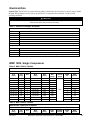
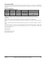
Approximate total square footage of insulation surface required for individual packaged chillers is tabulated
by evaporator code and can be found below.
Table 1, Insulation Quantity
8
WMC Model
Evaporator
Code
145S,
145D
150D
250D
290D
400D
E2209
E2209
E2212
E2609
E2612
E3012
Insulation
Area
sq. ft. (m2)
66 (6.1)
66 (6.1)
90 (8.3)
76 (7.1)
102 (9.4)
114 (11)
Magnitude™ Frictionless Centrifugal Chillers – Model WMC
IM 1029-2
Physical Data and Weights
With positive pressure systems, the pressure variance with temperature is always predictable, and the vessel
design and pressure relief protection are based upon pure refrigerant characteristics. R-134a requires ASME
vessel design, inspection and testing and uses spring-loaded pressure relief valves. When an over-pressure
condition occurs, spring-loaded relief valves purge only that quantity of refrigerant required to reduce the
pressure to the valve’s set pressure and then close. See Relief Valves section for additional information.
Evaporator
Refrigerant-side design pressure is 200 psi (1380 kPa). Water-side is 150 psi (1034 kPa).
Table 2, Evaporator Physical Data
WMC Model
Evaporator
Code
Tube
Length
145S,
145D
150D
250D
290D
400D
E2209
E2209
E2212
E2609
E2612
E3012
9 ft.
9 ft.
12 ft.
9 ft.
12 ft.
12 ft.
Unit Refrigerant
Charge
lb. (kg)
500 (227)
600 (272)
800 (363)
600 (272)
1100 (500)
1240 (562)
Evaporator
Water
Volume, gal (L)
38 (145)
38 (145)
45 (170)
61 (231)
72 (273)
88 (336)
Number of
Relief
Valves
1
1
1
1
1
1
Notes:
1. Refrigerant charge is for the entire unit and is approximate since the actual charge will depend on other variables. Actual charge will
be shown on the unit nameplate.
2. Water capacity is based on standard tube configuration and standard dished heads.
Condenser
Refrigerant-side design pressure is 200 psi (1380 kPa). Water-side design is 150 psi (1034 kPa).
Table 3, Condenser Physical Data
WMC Model
Condenser
Code
Tube
Length
Maximum
Pumpdown
Capacity lb. (kg)
724 (328)
971 (440)
883 (401)
1174 (533)
1676 (760)
Water
Volume
gal. (L)
47 (147)
62 (236)
61 (231)
72 (273)
111 (419)
Number of
Relief Valves
9 ft.
2
145S, 145D
C2009
12 ft.
2
150D
C2012
9 ft.
2
250D
C2209
12 ft.
2
290D
C2212
12 ft.
2
400D
C2612
Notes:
1. Condenser pumpdown capacity based on 90% full at 90°F.
2. Water capacity based on standard configuration and standard heads and can be less with lower tube counts.
IM 1029-2
Magnitude™ Frictionless Centrifugal Chillers – Model WMC
9
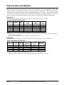
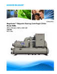
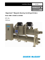
Mounting/Lifting/Total Weights
Drawings are for reference only and are not indicative of all unit configurations.
"LL"
"LW"
OH
RB
LB
LF
MFW
RF
X
Z
OL
MFL
OW
332834901
DRAWINGNUMBER
10
Magnitude™ Frictionless Centrifugal Chillers – Model WMC
00
NONE
REV.
SCALE
IM 1029-2
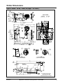
Chiller Dimensions
Figure 5, WMC
22.6
574
SUCTION
RELIEF 3,4
VALVE
145S, 2 Pass (See page 17 for notes.)
LB
RB
57.5
1460
4
WMC145SBS
26.9
684
CONDENSER
RELIEF
VALVES 3
332834001
00 NONE
DRAWINGNUMBER
Z
REV.
SCALE
X
22.5
571
EVAPORATOR
RELIEFVALVE
RF
5,13,14
LF
5,13
3,4
114.8
2916
81.0
2058
TOP
COMPR.
5,10,12
TOPVIEW
134.7 (UNITOVERALL)
3421 5,7,8
COMPRESSOR
18.0
458
3
17.1
435
O.I.T.S.
FRONT
END
BOX
74.3
1887
TOPFRONT
END BOX
UNIT
CTRL
BOX
58.3
1480
EVAPORATOR
RELIEFVALVE
44.3
5
1126
(OVERALL WIDTH)
37.8
960
5
32.7
831
5
69.8
1774
SUCTION
RELIEF
VALVE
4
IN
5
OUT
EVAPORATOR
3
65.9
1675
TOPUNIT
CTRL BOX
5
29.3
744
CONDENSER
RELIEF
VALVES
3
44.8
1137
OUT
IN
CONDENSER
Y
6.2
157
14.7
375
5.3
133
TYP. BOTH
ENDS
3
101.6
2579
112.1
2846
CL
5.6
142
INLET
13.0
330
INLET
Z
10.0
254
11.1
283
26.5
673
5,7,8
5.6
142
OUTLET
IN
RIGHTVIEW
6.0
152
NOM.
TYP.(2X)
13.0
330
INLET/
OUTLET
CL
CL
8.0
203
NOM.
TYP.(2X)
7,8
CONDENSERHEAD 2-PASS
VICTAULIC150 PSI WATERSIDE
114.8
2916
1.13
29
MTG. HOLE
(TYP.)
8.0
203
ELECTRICAL
CONNECTIONS
8.0
203
RB
MOUNTING
FOOT(TYP.)
9.0
230
UNITCTRL BOX
OUT
IN
5.6
143
INLET
7,8
LF
5.6
143
OUTLET
CL
OUT
EVAPORATORHEAD 2-PASS
VICTAULIC150 PSI WATERSIDE
LB
4.0
102
34.5
876
128.3
3259
FRONTVIEW
19.0
483
OUTLET
16.8
425
Y
X
FRONTEND BOX
14.0
357
34.5
876
11.3
287
6.3
160
8.9
225
5,13,14
16.0
407
31.9
809
RF
5,13
34.0
864
13.8
352
ALL DIMENSIONSAREIN DECMAL
INCHESAND [MILLIMATERS]
SEEDRAWING332835001 FORNOTES
IM 1029-2
Magnitude™ Frictionless Centrifugal Chillers – Model WMC
11
Figure 6, WMC
12
145D, 2 Pass (See page 17 for notes.)
Magnitude™ Frictionless Centrifugal Chillers – Model WMC
IM 1029-2
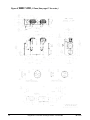
Figure 7, WMC
IM 1029-2
150D, 2-Pass (See page 17 for notes.)
Magnitude™ Frictionless Centrifugal Chillers – Model WMC
13
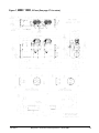
Figure 8, WMC
14
250D, 2-Pass (See page 17 for notes.)
Magnitude™ Frictionless Centrifugal Chillers – Model WMC
IM 1029-2
Figure 9, WMC
IM 1029-2
290D, 2-Pass (See page 17 for notes.)
Magnitude™ Frictionless Centrifugal Chillers – Model WMC
15
Figure 10, WMC
16
400D, 2-Pass (See page 17 for notes.)
Magnitude™ Frictionless Centrifugal Chillers – Model WMC
IM 1029-2
Drawing Notes
NOTES:
1. All dimensions are in inches and [millimeters] unless noted otherwise.
2. Final connections must allow for +/- 0.5 inch [12.7mm] manufacturing tolerances.
3. 1.00-inch FPT [25.4 mm] evaporator and condenser relief valves must be piped per ANSI / ASHRAE
15. Number of relief valves is 1 per evaporator and 2 per condenser.
4. 0.375 inch [9 mm] suction nozzle relief valve (dual compressor units only) must be piped per
ANSI / ASHRAE 15.
5. Minimum clearances are shown below.
Table 4 Minimum Clearance Requirements
WMC Model
145S, 145D
250D
150D, 290D
400D
One End
in. (mm)
Opposite End
in. (mm)
Sides & Top
in. (mm)
Electric Panels
in. (mm)
112 (2845)
36 (914)
36 (914)
48 (1219)
147 (3734)
36 (914)
36 (914)
48 (1219)
NOTES:
6.
7.
8.
9.
10.
11.
12.
13.
14.
15.
16.
a. The “One End” clearance is for tube removal and can be provided by a door or window.
b. Local codes may require greater than 48 inches for electric panel clearance.
3.25-inch [83mm] diameter lifting holes are provided. See installation manual for lifting instructions.
All water connections are given in standard U.S. pipe sizes. Standard connections are suitable for
welding or victaulic couplings.
The water connection shown is for the default configuration; your unit may be configured differently.
Orientation (left/right) is determined while facing the control panel. Consult the Item Summary sheet
for exact configuration. Unit shown has standard right-hand water connections. Left-hand
connections are available for either vessel. For left hand evaporator the inlet and outlet nozzles are
reversed. ANSI-flanged connections are available upon request. When using ANSI-flanged
connections add .500 inch [13 mm] to each flanged end.
Dimensions shown are for units (evaporator / condenser) with standard design pressures. The
refrigerant side design pressure is 200 PSI {1380 kPa} and the waterside design pressure is 150 PSI
{1034 kPa}. Consult the factory for unit dimensions with higher design pressures.
The unit vibration isolator pads are provided for field installation. When fully loaded - .250 inches [6
mm] thick.
These values are for units with standard wall thickness copper tubing only.
The shipping skid, when used, adds 6.00 inches [152 mm] to the overall unit height.
If main power wiring is brought up through the floor, this wiring must be outside the envelope of the
unit.
All power wiring is brought to the top of the power panel (Front End Box). Control wiring is brought
to the (Unit Control Box).
The unit is shipped with an operating charge of refrigerant.
Optional marine water box connections are available upon request.
Harmonic Filter Dimensions
Contact the local Daikin McQuay sales office for harmonic filter dimensions for specific applications.
IM 1029-2
Magnitude™ Frictionless Centrifugal Chillers – Model WMC
17
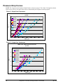
Pressure Drop Curves
NOTE: The Evaporator and Condenser Model Codes are shown on page 9. The -B and -C designations shown
on the curves refer to vessel tube count, which is determined by the computer selection program.
Figure 11, Single Pass Evaporators
WMC Evap - Water Side Pressure Drop
(1 pass)
30
E2212-B
E2212-C
E2212-D
25
E2209-B
E2209-C
EPD - ft
20
E2209-D
E2612-B
E2609-B
15
E3012-B
E3012-C
10
5
0
0
500
1000
1500
2000
2500
3000
3500
4000
EGPM - gpm
Figure 12, Single Pass Condensers
WMC Cond - Water Side Pressure Drop
(1 pass)
25.0
C2012-B
C2012-C
20.0
C2009-B
C2009-C
C2212-B
C2212-C
CPD - ft
15.0
C2209-B
C2209-C
C2612-B
10.0
C2612-C
5.0
0.0
0
500
1000
1500
2000
2500
3000
3500
4000
4500
5000
CGPM - gpm
18
Magnitude™ Frictionless Centrifugal Chillers – Model WMC
IM 1029-2
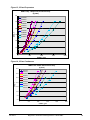
Figure 13, 2-Pass Evaporators
WMC Evap - Water Side Pressure Drop
(2 pass)
60
E2212-B
E2212-C
E2212-D
50
E2209-B
E2209-C
E2209-D
40
EPD - ft
E2612-B
E2609-B
E3012-B
30
E3012-C
20
10
0
0
500
1000
1500
2000
EGPM - gpm
Figure 14, 2-Pass Condensers
WMC Cond - Water Side Pressure Drop
(2 pass)
35.0
C2012-B
C2012-C
30.0
C2009-B
C2009-C
25.0
C2212-B
CPD - ft
C2212-C
C2209-B
20.0
C2209-C
C2612-B
15.0
C2612-C
10.0
5.0
0.0
0
500
1000
1500
2000
2500
CGPM - gpm
IM 1029-2
Magnitude™ Frictionless Centrifugal Chillers – Model WMC
19
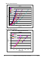
Figure 15, 3-Pass Evaporators
WMC Evap - Water Side Pressure Drop
(3 pass)
90
E2212-C
E2212-D
80
E2209-C
E2209-D
70
E2612-B
E2609-B
EPD - ft
60
E3012-C
50
40
30
20
10
0
0
200
400
600
800
1000
1200
EGPM - gpm
Figure 16, 3-Pass Condensers
WMC Cond - Water Side Pressure Drop
(3 pass)
60.0
C2012-C
C2009-C
50.0
C2212-C
C2209-C
CPD - ft
40.0
C2612-C
30.0
20.0
10.0
0.0
0
200
400
600
800
1000
1200
1400
CGPM - gpm
20
Magnitude™ Frictionless Centrifugal Chillers – Model WMC
IM 1029-2
Relief Valves
As a safety precaution and to meet code requirements, each
chiller is equipped with pressure relief valves located on the
condenser and evaporator for the purpose of relieving excessive
refrigerant pressure (caused by equipment malfunction, fire,
etc.) to the atmosphere. Most codes require that relief valves be
vented to the outside of a building and this is a desirable
practice for all installations. Relief piping connections to the
relief valves must have flexible connectors.
Note: Remove plastic shipping plugs (if installed) from
the inside of the valves prior to making pipe connections.
Whenever vent piping is installed, the lines must be run in
accordance with local code requirements; where local
codes do not apply, the latest issue of ANSI/ASHRAE
Standard 15 code recommendations must be followed.
•
Condensers have two 200 psi, 1.0-inch female NPT relief
valves as a set with a three-way valve separating the two
valves. One valve remains active at all times and the second
valve acts as a standby.
•
Evaporators have a single 200 psi valve. Each valve has a 1.0-inch female NPT connection.
•
Each suction line on dual compressor units has a single 200 psig relief valve rated at 6.9 lb/min air with a
3/8-inch flare connection.
•
Vessel valve capacity is 75 lb/min air.
Figure 17, Condenser 3-Way Relief Valve
Refrigerant Vent Piping
Vessel relief valve connection size is 1-inch FPT and are in the quantity shown in Table 2 and Table 3 on
page 9. Twin relief valves mounted on a transfer valve are used on the condenser so that one relief valve can
be shut off and removed for testing, leaving the other in operation. Only one of the two is in operation at any
time.
Vent piping is sized for only one valve of the set (but connected to both) since only one can be in operation at
a time. In no case would a combination of evaporator and condenser sizes require more refrigerant than the
pumpdown capacity of the condenser. Condenser pumpdown capacities are based on the current
ANSI/ASHRAE Standard 15 that recommends 90% full at 90°F (32°C).
IM 1029-2
Magnitude™ Frictionless Centrifugal Chillers – Model WMC
21
Sizing Vent Piping (ASHRAE Method)
Relief valve pipe sizing is based on the discharge capacity for the given evaporator or condenser and the
length of piping to be run. Discharge capacity for R-134a vessels is calculated using a complicated equation
that accounts for equivalent length of pipe, valve capacity, Moody friction factor, pipe ID, outlet pressure and
back pressure. The formula and tables are contained in ASHRAE Standard 15-2001.
The Daikin McQuay Magnitude centrifugal units have a relief valve setting of 200 psi.
Using the ASHRAE formula and basing calculations on the 225 psi design yields a conservative pipe size,
which is summarized in Table 5. The table gives the pipe size required per relief valve. When valves are
piped together, the common piping must follow the rules set out in the following paragraph on common
piping.
Table 5. Relief Valve Piping Sizes
Equivalent length (ft)
Pipe Size inch (NPT)
Moody Factor
2.2
1 1/4
0.0209
18.5
1 1/2
0.0202
105.8
2
0.0190
296.7
2 1/2
0.0182
973.6
3
0.0173
4117.4
4
0.0163
NOTE: A 1-inch pipe is too small to handle these valves. A pipe increaser must always be installed at the valve outlet.
Common Piping
According to ASHRAE Standard 15, the pipe size cannot be less than the relief valve outlet size. The
discharge from more than one relief valve can be run into a common header, the area of which cannot be less
than the sum of the areas of the connected pipes. For further details, refer to ASHRAE Standard 15. The
common header can be calculated by the formula:
0.5
DCommon = D12 + D22 .... Dn2
The above information is a guide only. Consult local codes and/or latest version of ASHRAE Standard 15 for
sizing data.
22
Magnitude™ Frictionless Centrifugal Chillers – Model WMC
IM 1029-2
Electrical Information
Wiring, fuse and wire size must be in accordance with the National Electric Code (NEC).
Important: The voltage to these units must be within ±10% of nameplate voltage, and the voltage unbalance
between phases must not exceed 2%. Since a 2% voltage unbalance will cause a current unbalance of 6 to 10
times the voltage unbalance per NEMA MG-1, 1998 Standard, it is most important that the unbalance between
phases be kept at a minimum.
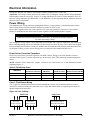
Power Wiring
The standard power wiring connection to Magnitude chillers is single point to a common disconnect switch
which is then factory-wired to individual disconnect switches for each circuit.
Proper phase sequence to the unit is not required as far as the unit operation is concerned. Correct motor
rotation is established by the chiller control system regardless of the connected phase sequence.
!
DANGER
Qualified and licensed electricians must perform wiring. An electrical shock hazard exists that
can cause severe injury or death.
The field power wiring required varies depending on unit model, and if optional EMI filters and/or harmonic
filters (including tuning reactors and referred to in this manual as combo harmonic filters) have been ordered.
Factory-mounted and wired line reactors are standard, but discarded when the optional combo harmonic filters
are included. Table 6 gives the various wiring cases as a function of unit model and filters used.
Power Factor Correction Capacitors
Do not use power factor correction capacitors with WMC chillers. Doing so can cause harmful electrical
resonance in the system. Correction capacitors are not necessary since VFDs inherently maintain high power
factors
NOTE: Harmonic filter dimensions, weights, connection size and location are in the Dimension Section
beginning on page 17.
Table 6, Field Wiring Cases
Standard With
Standard Line Reactors
With Optional
EMI Filters
WMC 145S
Case 1
Case 7
Case 8
Case 9
WMC 145D, 150D
Case 1
Case 2
Case 5
Case 6
WMC 250D, 290D, 400D
Case 1
Case 2
Case 3
Case 4
WMC Model
With Optional Combo With Optional Combo
Harmonic Filters
Harmonic Filters and EMI
Case 1, Field Power Wiring
Case 1 applies to standard units that also include standard line reactors. The standard connection is to two
disconnect switches on multi-point connection or to a single disconnect switch (or optional power block) on
optional single-point connection.
Figure 18, Case 1 Wiring
Multi-Point
Disconnect
Switch, Circuit #1
IM 1029-2
Disconnect
Switch, Circuit #2
Single-Point
Disconnect Switch or
Optional Power Block
Magnitude™ Frictionless Centrifugal Chillers – Model WMC
23
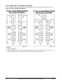
Case 2, WMC 145D – 400D Field Power Wiring
Case 2 adds optional factory-mounted and wired EMI filters. The actual field wiring is the same as Case 1.
Figure 19, Case 2 Field Power Wiring
NOTES:
1. Optional EMI Filter
2. Remove standard line reactor when optional combination line reactor/harmonic filter assembly is used.
3. Circuit breakers shown in the diagram function exclusively as disconnect switches.
24
Magnitude™ Frictionless Centrifugal Chillers – Model WMC
IM 1029-2
Case 3, WMC 250D, 290D, 400D Field Power Wiring
Case 3 adds the combo harmonic filters. The standard line reactors are shipped in the unit and are removed
and discarded in the field. Field wiring to the harmonic filter would be the same size as the incoming lines.
Figure 20 shows the optional multi-point connection to two disconnect switches. The standard would be a
single-point connection to a single disconnect switch.
Figure 20, Case 3 Field Power Wiring
NOTES:
1. Not applicable
2. Remove standard line reactor when optional combination line reactor/harmonic filter assembly is used.
3. Circuit breakers shown in the diagram function exclusively as disconnect switches.
IM 1029-2
Magnitude™ Frictionless Centrifugal Chillers – Model WMC
25
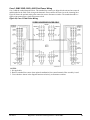
Case 4, WMC 250D, 290D, 400D Field Power Wiring
Case 4 adds both the EMI filters and the combo harmonic filters.
The EMI is factory mounted and the line side of the EMI is factory wired, the load side is field wired to the
remotely mounted harmonic filter.
The standard line reactors are shipped in the unit and are removed and discarded in the field. The field wiring
size to and from the harmonic filter should be the same as the incoming lines.
Figure 21 shows the optional multi-point connection to two disconnect switches. The standard would be a
single-point connection to a single disconnect switch. The balance of the wiring remains the same.
Figure 21, Case 4 Field Power Wiring
NOTES:
1. Optional EMI Filter
2. Remove standard line reactor when optional combination line reactor/harmonic filter assembly is used.
3. Circuit breakers shown in the diagram function exclusively as disconnect switches.
26
Magnitude™ Frictionless Centrifugal Chillers – Model WMC
IM 1029-2
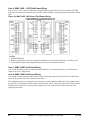
Case 5, WMC 145D – 150D Field Power Wiring
Case 5 adds remote-mounted combo harmonic filters. In these model WMCs the fuses are located in the
compressor. Field wiring is run from the disconnect switch load side to the power block in the remote filter.
The standard line reactors are shipped in the unit and are removed and discarded in the field. A shipped loose
power block is field mounted in their former location and one side is wired to the remote filter. The wires that
originally ran from the line reactor up to the compressor are now connected to the other side of the power
block.
NOTE: the fuses and compressor shown in the “Chiller” block are located in the compressors on these
models, not in the power panel. The wire routing is shown in Figure 22.
Figure 22, WMC 145D, 150D Case 5 Field Power Wiring
NOTES:
1. Not applicable.
2. Remove standard line reactor when optional combination line reactor/harmonic filter assembly is used.
3. Circuit breakers shown in the diagram function exclusively as disconnect switches.
IM 1029-2
Magnitude™ Frictionless Centrifugal Chillers – Model WMC
27
Case 6, WMC 145D – 150D Field Power Wiring
Refer to Case 5. Case 6 merely adds factory-mounted EMIs to the load side of the circuit breaker. The EMI
load side is wired out to the harmonic filter. In other words, the EMI is interposed between the breaker and the
filter
Figure 23, WMC 145D, 150D Case 6 Field Power Wiring
NOTES:
1. Optional EMI Filter
2. Remove standard line reactor when optional combination line reactor/harmonic filter assembly is used.
3. Circuit breakers shown in the diagram function exclusively as disconnect switches.
Case 7, WMC 145S Field Power Wiring
Case 7 adds an optional factory-mounted and wired EMI filter. The actual field wiring is to the disconnect
switch as in Case 1, Single-Point.
Case 8, WMC 145S Field Power Wiring
Case 8 adds a remote-mounted combo harmonic filter. Field wiring runs from the load side of the disconnect
switch to the power block in the remote harmonic filter.
The standard line reactors are shipped in the unit and are removed and discarded in the field. A shipped loose
power block is field mounted in their former location and one side is wired to the remote filter. The wires that
originally ran from the line reactor up to the compressor are now connected to the other side of the field
supplied power block.
28
Magnitude™ Frictionless Centrifugal Chillers – Model WMC
IM 1029-2
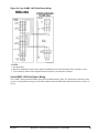
Figure 24, Case 8 WMC 145S Field Power Wiring
NOTES:
1. Not applicable
2. Remove standard line reactor when optional combination line reactor/harmonic filter assembly is used.
3. Circuit breakers shown in the diagram function exclusively as disconnect switches.
Case 9 WMC 145S Field Power Wiring
Case 9 adds a factory-mounted EMI to the remote-mounted harmonic filter. The field wiring remains the same
as Case 8 except that the wiring out to the filter emanates from the EMI rather than the disconnect switch as in
Case 8.
IM 1029-2
Magnitude™ Frictionless Centrifugal Chillers – Model WMC
29
Optional Harmonic Filter
The optional harmonic filters are field mounted and wired option, wired from the chiller power panel circuit
breakers out to the filter and back to the chiller’s power fuses and contactors. They limit current distortion to
less than 7% and meet IEEE 519 standards chiller power factor is improved across the entire load range. The
filters are mounted in a UL Type 1 enclosure and are UL and cUL listed. Model HG60 is wall mounted, the
balance are floor mounted.
!
WARNING
Only qualified electricians should carry out all electrical installation and maintenance work on the
harmonic filter.
!
WARNING
All wiring must be in accordance with the National Electrical Code (NEC) and/or any other codes
that apply to the installation site.
!
WARNING
Disconnect all power before working on the equipment. Do not attempt any work on a powered
HG7 filter.
!
WARNING
The HG7 harmonic filter, drive, motor, and other connected equipment must be properly grounded.
! WARNING
After switching off the power, always allow 5 minutes for the capacitors in the HG7 filter and in
the drive to discharge before working on the HG7, the drive, the motor, or the connecting wiring. It
is a good idea to check with a voltmeter to make sure that all sources of power have been
disconnected and that all capacitors have discharged before beginning work.
Mounting
As is the case with the chiller unit, the filter must be mounted in an indoor location suitable for a type 1
enclosure. Provide sufficient access and working space around the unit to permit ready and safe installation.
The installation must conform to all working space and clearance requirements of the National Electrical
Code (NEC) and/or any other applicable codes. Provide sufficient unobstructed space to allow cooling air to
flow through the front and sides of the unit. The filter must be mounted vertically on a smooth, solid surface,
free from heat, dampness, and condensation.
Power Wiring
Refer to the power wiring diagrams beginning on page 23. Route the conduit and wiring from the chiller
power panel to the filter and then back to the power panel. The compressor variable speed drives are located
in the compressors. The harmonic filter is provided with internal fuses. Additional fuses may be required at
the connecting point to protect the tap conductors. Refer to the National Electrical Code (NEC) and/or any
other applicable codes.
Cable Entry Locations: The harmonic filters are not provided with enclosure wiring knockouts. Typical or
recommended cable entry locations are shown on the drawings located in this section of this manual. A
selection can be made at the time of installation to best suit job conditions.
Field Wiring Connection Terminals: Compression type terminals are provided for all field wiring
connections. The control circuit terminals will accommodate 18 AWG to 10 AWG wire and should be
tightened to 7 lbs. - in. torque.
The wire size range and tightening torque for the grounding and power terminals are listed on the filter
dimension drawings.
30
Magnitude™ Frictionless Centrifugal Chillers – Model WMC
IM 1029-2
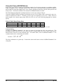
Electrical Data
General Note: The RLA for use in the following tables is obtained by the selection of a specific unit by Daikin
McQuay. When shipped, a unit will bear the specific RLA, stamped on the nameplate, for the selected
operating conditions.
!
CAUTION
The RLA stamped on the unit may be lower than the minimum shown in the following tables, in which case the
minimum table value must be used for wire sizing.
Table 7, Electrical Acronyms and Notes
ACRONYMS:
DS
LRA
N/A
MCA
MOP
PB
Disconnect switch
Locked rotor amps
Not available
Minimum circuit ampacity
Maximum overcurrent protection
Power block
RLA
Rated load amps
NOTES:
1
2
3
In all cases, a disconnect switch is supplied for each compressor circuit.
RLA and LRA data is for each compressor
Wire size per NEC 2008, table 310.16, 75° C, copper
4
MOP size per NEC 2008, section 440.22(a) for air conditioning and refrigeration equip.
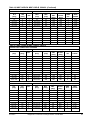
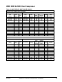
WMC 145S, Single Compressor
Table 8, WMC 145S-B, 3/60/460
SINGLE POINT CONNECTION, STANDARD
COMPRESSOR
CHILLER
DISC.
POWER
SWT.
BLOCK
[Amp]
[Amp]
RLA
[Amp]
LRA
[Amp]
QTY
MCA
[Amp]
MOP
[Amp]
79 to 80
81 to 88
89 to 92
93 to 99
110
110
110
110
1
1
1
1
99 to 100
101 to 110
111 to 115
116 to 123
175
175
200
200
150
150
150
150
WIRE
QTY
WIRE
GAUGE
3
3
3
3
3 GA
2 GA
2 GA
1 GA
3
1 GA
3
3
1 GA
1/0
100
110
1
125
225
150
101 to 104
105 to 111
132
132
1
1
126 to 130
131 to 138
225
225
200
200
112 to 120
132
1
140 to 150
250
200
3
1/0
121 to 133
154
1
151 to 166
250
225
3
2/0
134 to 140
154
1
167 to 175
300
225
3
2/0
141 to 150
165
1
176 to 187
300
225
3
3/0
WIRE
QTY
WIRE
GAUGE
N/A
Table 9, WMC 145S-B, 3/50/400
SINGLE POINT CONNECTION, STANDARD
COMPRESSOR
RLA
[Amp]
IM 1029-2
LRA
[Amp]
CHILLER
QTY
MCA
[Amp]
MOP
[Amp]
DISC.
SWT.
POWER
BLOCK
Magnitude™ Frictionless Centrifugal Chillers – Model WMC
31
[Amp]
100 to 104
105 to 111
112 to 120
121 to 133
132
132
132
165
1
1
1
1
125 to 130
132 to 139
140 to 150
152 to 167
225 Amps
225 Amps
250 Amps
250 Amps
200
200
200
225
134 to 140
165
1
168 to 175
300 Amps
225
141 to 150
151 to 155
165
176
1
1
177 to 188
189 to 194
300 Amps
300 Amps
156 to 160
176
1
195 to 200
350 Amps
[Amp]
3
3
3
3
3 GA
2 GA
2 GA
1 GA
3
1 GA
225
250
3
3
1 GA
1/0
250
3
1/0
N/A
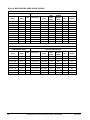
WMC 145D & 150D, Dual Compressor
Table 10, WMC 145D-B & WMC 150D-B, 3/60/460
SINGLE POINT CONNECTION, STANDARD
COMPRESSOR (EACH)
CHILLER
POWER
DISC.
SWT.
BLOCK
[Amp]
[Amp]
RLA
[Amp]
LRA
[Amp]
QTY
MCA
[Amp]
MOP
[Amp]
WIRE
QTY
WIRE
GAUGE
52 to 53
54 to 57
58 to 61
71
71
71
2
2
2
117 to 120
122 to 129
131 to 138
150
175
175
250
250
250
760
760
760
3
3
3
1 GA
1 GA
1/0
62 to 64
71
2
140 to 144
200
250
760
3
1/0
65 to 69
70 to 76
77
88
88
88
2
2
2
147 to 156
158 to 171
173
200
225
250
250
250
250
760
760
760
3
3
3
2/0
2/0
2/0
78 to 80
88
2
81 to 88
89 to 92
110
110
2
2
176 to 180
250
250
760
3
3/0
182 to 198
200 to 207
250
250
250
250
760
760
3
3
3/0
4/0
93 to 100
110
2
209 to 225
300
250
760
3
4/0
101 to 102
103 to 107
108 to 113
132
132
132
2
2
2
227 to 230
232 to 241
243 to 254
300
300
350
400
400
400
760
760
760
3
3
3
4/0
250MCM
250MCM
114 to 120
132
2
257 to 270
350
400
760
3
300MCM
Continued next page.
32
Magnitude™ Frictionless Centrifugal Chillers – Model WMC
IM 1029-2
Table 10, WMC 145D-B & WMC 150D-B, 3/60/460 (Continued)
MULTI-POINT CONNECTION, OPTIONAL
COMPRESSOR (EACH)
RLA
[Amp]
LRA
[Amp]
QTY
MCA
[Amp]
52
53 to 55
56 to 64
65 to 68
69 to 77
78 to 80
81 to 88
89 to 92
93 to 99
100
101 to 104
105 to 111
112 to 120
71
71
71
88
88
88
110
110
110
110
132
132
132
2
2
2
2
2
2
2
2
2
2
2
2
2
65
66 to 69 A
70 to 80 A
82 to 85 A
86 to 97 A
98 to 100
101 to 110
111 to 115
116 to 124
125
126 to 130
131 to 139
140 to 150
CHILLER (PER CIRCUIT)
DISC.
POWER
MOP
BLOCK
SWT.
[Amp]
[Amp]
[Amp]
110
110
125
150
150
175
175
200
200
225
225
225
250
100
100
100
125
125
125
150
150
150
150
200
200
200
N/A
N/A
N/A
N/A
N/A
N/A
N/A
N/A
N/A
N/A
N/A
N/A
N/A
WIRE
QTY
WIRE
GAUGE
3
3
3
3
3
3
3
3
3
3
3
3
3
6 GA
4 GA
4 GA
4 GA
3 GA
3 GA
2 GA
2 GA
1 GA
1 GA
1 GA
1/0
1/0
Table 11, WMC 145D-B & WMC 150D-B, 3/60/575
SINGLE POINT CONNECTION, STANDARD
COMPRESSOR (EACH)
CHILLER
POWER
DISC.
SWT.
BLOCK
[Amp]
[Amp]
RLA
[Amp]
LRA
[Amp]
QTY
MCA
[Amp]
MOP
[Amp]
WIRE
QTY
WIRE
GAUGE
51
52 to 53
54 to 57
58 to 61
62 to 64
71
71
71
71
71
2
2
2
2
2
115
117 to 120
122 to 128
131 to 138
140 to 144
150
150
175
175
200
250
250
250
250
250
760
760
760
760
760
3
3
3
3
3
2 GA
1 GA
1 GA
1/0
1/0
65 to 69
70 to 76
77
78 to 80
88
88
88
88
2
2
2
2
147 to 155
158 to 171
173
176 to 180
200
225
250
250
250
250
250
250
760
760
760
760
`
3
3
3
2/0
2/0
2/0
3/0
81 to 88
89 to 92
93 to 100
110
110
110
2
2
2
182 to 198
200 to 207
209 to 225
250
250
300
250
250
250
760
760
760
3
3
3
3/0
4/0
4/0
WIRE
QTY
WIRE
GAUGE
MULTI-POINT CONNECTION, OPTIONAL
COMPRESSOR (EACH)
CHILLER (PER CIRCUIT)
DISC.
POWER
MOP
SWT.
BLOCK
[Amp]
[Amp]
[Amp]
RLA
[Amp]
LRA
[Amp]
QTY
MCA
[Amp]
51 to 52
53 to 55
56 to 64
71
71
71
2
2
2
64 to 65 A
66 to 69
70 to 80 A
110
110
125
100
100
100
N/A
N/A
N/A
3
3
3
6 GA
4 GA
4 GA
65 to 68
69 to 77
78 to 80
88
88
88
2
2
2
82 to 85 A
86 to 97 A
98 to 100
150
150
175
125
125
125
N/A
N/A
N/A
3
3
3
4 GA
3 GA
3 GA
81 to 88
89 to 92
93 to 99
100
110
110
110
110
2
2
2
2
101 to 110
111 to 115
116 to 124
125
175
200
200
225
150
150
150
150
N/A
N/A
N/A
N/A
3
3
3
3
2 GA
2 GA
1 GA
1 GA
IM 1029-2
Magnitude™ Frictionless Centrifugal Chillers – Model WMC
33
Table 12, WMC 145D-B & WMC 150D-B, 3/50/400
SINGLE POINT CONNECTION, STANDARD
COMPRESSOR (EACH)
CHILLER
POWER
DISC.
BLOCK
SWT.
[Amp]
[Amp]
RLA
[Amp]
LRA
[Amp]
QTY
MCA
[Amp]
MOP
[Amp]
WIRE
QTY
WIRE
GAUGE
63 to 69
88
2
142 to 156
200
250
70 to 76
77
88
88
2
2
158 to 171
174
225
250
250
250
760
3
2/0
760
760
3
3
2/0
2/0
78 to 80
88
2
176 to 180
250
250
760
3
3/0
81 to 88
89 to 92
110
110
2
2
183 to 198
201 to 207
250
250
250
250
760
760
3
3
3/0
4/0
93 to 100
110
2
210 to 225
300
250
760
3
4/0
101 to 102
103 to 107
108 to 113
132
132
132
2
2
2
228 to 230
232 to 241
243 to 255
300
300
350
400
400
400
760
760
760
3
3
3
4/0
250MCM
250MCM
114 to 120
132
2
257 to 270
350
400
760
3
300MCM
MULTI-POINT CONNECTION, OPTIONAL
COMPRESSOR (EACH)
34
CHILLER (PER CIRCUIT)
DISC.
POWER
MOP
SWT.
BLOCK
[Amp]
[Amp]
[Amp]
150
250
760
150
250
760
RLA
[Amp]
LRA
[Amp]
QTY
MCA
[Amp]
WIRE
QTY
WIRE
GAUGE
63 to 68
69 to 77
88
88
2
2
79 to 85
87 to 97
3
3
4 GA
3 GA
78 to 80
88
2
98 to 100
175
250
760
3
3 GA
81 to 88
110
2
102 to 110
175
89 to 92
110
2
112 to 115
200
250
760
3
2 GA
250
760
3
2 GA
93 to 99
110
2
117 to 124
200
250
760
3
1 GA
100
110
2
125
225
250
760
3
1 GA
101 to 104
105 to 111
132
132
2
2
127 to 130
132 to 139
225
225
400
400
760
760
3
3
1 GA
1/0
112 to 120
132
2
140 to 150
250
400
760
3
1/0
Magnitude™ Frictionless Centrifugal Chillers – Model WMC
IM 1029-2
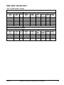
WMC 250D & 290D, Dual Compressor
Table 13, WMC 250D-B & WMC 290D-B, 3/60/460
SINGLE POINT CONNECTION, STANDARD
COMPRESSOR (Each)
CHILLER
DISC.
POWER
SWT.
BLOCK
[Amp]
[Amp]
RLA
[Amp]
LRA
[Amp]
QTY
MCA
[Amp]
MOP
[Amp]
79 to 88
89 to 92
110
110
2
2
178 to 198
201 to 208
250
250
250
250
WIRE
QTY
WIRE
GAUGE
760
760
3
3
3/0
4/0
93 to 100
110
2
210 to 226
300
250
760
3
4/0
101 to 107
108 to 113
132
132
2
2
228 to 241
244 to 255
300
350
400
400
760
760
3
3
250 MCM
250 MCM
114 to 120
132
2
257 to 271
350
400
760
3
300 MCM
121 to 123
124 to 126
127 to 137
138
154
154
154
154
2
2
2
2
273 to 277
280 to 284
286 to 309
311
350
400
400
400
400
400
400
400
760
760
760
760
3
3
3
3
300 MCM
300 MCM
350 MCM
400 MCM
139 to 140
154
2
313 to 316
450
400
760
3
400 MCM
141 to 149
165
2
318 to 335
450
400
760
3
400 MCM
150
165
2
338 Amps
450
400
760
3
500 MCM
WIRE
QTY
WIRE
GAUGE
MULTI POINT CONNECTION, OPTIONAL
COMPRESSOR (EACH)
CHILLER (PER CIRCUIT)
POWER
DISC.
MOP
SWT.
BLOCK
[Amp]
[Amp]
[Amp]
RLA
[Amp]
LRA
[Amp]
QTY
MCA [Amp]
79 to 80
81 to 88
89 to 92
93 to 99
110
110
110
110
2
2
2
2
99 to 100
101 to 110
111 to 115
116 to 123
175
175
200
200
150
150
150
150
N/A
N/A
N/A
N/A
3
3
3
3
3 GA
2 GA
2 GA
1 GA
100
110
2
125
225
150
N/A
3
1 GA
101 to 104
105 to 111
132
132
2
2
126 to 130
131 to 138
225
225
200
200
N/A
N/A
3
3
1 GA
1/0
112 to 120
132
2
140 to 150
250
200
N/A
3
1/0
121 to 133
154
2
151 to 166
250
225
N/A
3
2/0
134 to 140
154
2
167 to 175
300
225
N/A
3
2/0
141 to 150
165
2
176 to 187
300
225
N/A
3
3/0
IM 1029-2
Magnitude™ Frictionless Centrifugal Chillers – Model WMC
35
Table 14, WMC 250D-B & WMC 290D-B, 3/50/400
SINGLE POINT CONNECTION, STANDARD
COMPRESSOR (EACH)
CHILLER
DISC.
POWER
SWT.
BLOCK
[Amp]
[Amp]
RLA
[Amp]
LRA
[Amp]
QTY
MCA [Amp]
MOP
[Amp]
WIRE
QTY
WIRE
GAUGE
100 to 107
108 to 113
132
132
2
2
225 to 241
243 to 255
300
350
400
400
760
760
3
3
250 MCM
250 MCM
114 to 120
132
2
257 to 270
350
400
760
3
300 MCM
121 to 123
124 to 126
165
165
2
2
273 to 277
279 to 284
350
400
400
400
760
760
3
3
300 MCM
300 MCM
127 to 137
165
2
138
139 to 148
149 to 150
151 to 153
165
165
165
176
2
2
2
2
286 to 309
400
400
760
3
350 MCM
311
313 to 333
336 to 338
340 to 345
400
450
450
450
400
400
400
400
760
760
760
760
3
3
3
3
400 MCM
400 MCM
500 MCM
500 MCM
154 to 160
176
2
347 to 360
500
400
760
3
500 MCM
WIRE
QTY
WIRE
GAUGE
MULTI POINT CONNECTION, OPTIONAL
COMPRESSOR (EACH)
36
CHILLER (PER CIRCUIT)
DISC.
POWER
MOP
SWT.
BLOCK
[Amp]
[Amp]
[Amp]
RLA
[Amp]
LRA
[Amp]
QTY
MCA [Amp]
100 to 104
132
1
125 to 130
225 Amps
200
N/A
3
1 GA
105 to 111
132
1
132 to 139
225 Amps
200
N/A
3
1/0
112 to 120
132
1
140 to 150
250 Amps
200
N/A
3
1/0
121 to 133
165
1
152 to 167
250 Amps
225
N/A
3
2/0
134 to 140
165
1
168 to 175
300 Amps
225
N/A
3
2/0
141 to 150
165
1
177 to 188
300 Amps
225
N/A
3
3/0
151 to 155
176
1
189 to 194
300 Amps
250
N/A
3
3/0
156 to 160
176
1
195 to 200
350 Amps
250
N/A
3
3/0
Magnitude™ Frictionless Centrifugal Chillers – Model WMC
IM 1029-2
WMC 400D 3/60/460 ONLY
Table 15, WMC 400D-B, 3/60/460
SINGLE POINT CONNECTION, STANDARD
COMPRESSOR (EACH)
RLA
[Amp]
LRA
[Amp]
QTY
MCA
[Amp]
MOP
[Amp]
126
127 to 137
138
139 to 148
149 to 153
176
176
176
176
176
2
2
2
2
2
284
286 to 309
311
313 to 334
336 to 345
400
400
400
450
450
154 to 160
176
2
347 to 361
500
CHILLER
DISC.
POWER
SWT.
BLOCK
[Amp]
[Amp]
400
760
400
760
400
760
400
760
400
760
400
760
WIRE
QTY
WIRE
GAUGE
3
3
3
3
3
300 MCM
350 MCM
400 MCM
400 MCM
500 MCM
3
500 MCM
WIRE
QTY
WIRE
GAUGE
3
3
3
2/0
2/0
3/0
3
3/0
MULTI-POINT CONNECTION, OPTIONAL
COMPRESSOR (EACH)
RLA
[Amp]
LRA
[Amp]
QTY
MCA
[Amp]
126 to 133
134 to 140
141 to 155
176
176
176
2
2
2
157 to 166
167 to 175
176 to 193
156 to 160
176
2
195 to 200
IM 1029-2
CHILLER (PER CIRCUIT)
DISC.
POWER
MOP
SWT.
BLOCK
[Amp]
[Amp]
[Amp]
250
250
N/A
300
250
N/A
300
250
N/A
350
250
N/A
Magnitude™ Frictionless Centrifugal Chillers – Model WMC
37
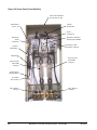
Figure 25, Power Panel (Front End Box)
Power Cable Entrance
Access Plate on Top
Transformers
T2, T3, T4
Current
Transformer
Power
Connection
Disconnect
switch
w/Lockout,
Ground
Fault Relay
Disconnect Switch w/
Thru-the-Door Handle
Disconnect switch
w/Lockout, Comp #2
Transformer
T1
Power System
Filter EMI
Comp #2
Power System
Filter EMI
Comp #1
Control Power
Interrupt Relay
(4) Control
Power Fuses
Drive Reactor
Comp #1
38
Drive Reactor
Comp #2
Magnitude™ Frictionless Centrifugal Chillers – Model WMC
IM 1029-2
Figure 26, Control Panel
EXV Board
Field Wiring Knockouts
Terminal Board
TB UTB1 for Field
Wiring Connections
On/Off
Switches
UNIT
COMP #1
COMP #2
Controller
OITS PC
Universal
Communication
Module
Comp #1 I/O
IM 1029-2
Magnitude™ Frictionless Centrifugal Chillers – Model WMC
Comp #2 I/O
39
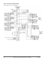
Figure 27, Field Control Wiring Diagram
NOTE: Complete notes are on the following page.
40
Magnitude™ Frictionless Centrifugal Chillers – Model WMC
IM 1029-2
Field Wiring Diagram Notes
1.
•
COMPRESSOR FRONT END BOX IS FACTORY MOUNTED AND WIRED. ALL LINE SIDE WIRING MUST BE
WIRED IN ACCORDANCE WITH THE NEC AND BE MADE WITH COPPER WIRE AND COPPER LUGS ONLY.
USE ONLY COPPER SUPPLY WIRES WITH AMPACITY BASED ON 75°C CONDUCTOR RATING. MAIN POWER
WIRING BETWEEN THE FRONT END BOX AND COMPRESSOR TERMINALS IS FACTORY INSTALLED.
MINIMUM WIRE SIZE FOR 115 VAC IS 12 GA. FOR A MAXIMUM LENGTH OF 50 FEET. IF GREATER THAN 50
FEET REFER TO MCQUAY FOR RECOMMENDED WIRE SIZE MINIMUM. WIRE SIZE FOR 24 VAC IS 18 GA.
ALL WIRING TO BE INSTALLED AS NEC CLASS 1 WIRING SYSTEM. ALL 24 VAC WIRING MUST BE RUN IN
SEPARATE CONDUIT FROM 115 VAC WIRING. WIRING MUST BE WIRED IN ACCORDANCE WITH NEC AND
CONNECTION TO BE MADE WITH COPPER WIRE ANC COPPER LUGS ONLY.
2.
FOR OPTIONAL SENSOR WIRING SEE UNIT CONTROL DIAGRAM. IT IS RECOMMENDED THAT DC WIRES
BE RUN SEPARATELY FROM 115 VAC WIRING.
3.
A CUSTOMER FURNISHED 24 OR 120 VAC POWER FOR ALARM RELAY COIL MAY BE CONNECTED
BETWEEN UTB1 TERMINALS 84 POWER AND 81 NEUTRAL OF THE CONTROL PANEL. FOR NORMALLY
OPEN CONTACTS WIRE BETWEEN 82 & 81. FOR NORMALLY CLOSED WIRE BETWEEN 83 & 81. THE ALARM
IS OPERATOR PROGRAMMABLE. MAXIMUM RATING OF THE ALARM RELAY COIL IS 25VA.
4.
REMOTE ON/OFF CONTROL OF UNIT CAN BE ACCOMPLISHED BY INSTALLING A SET OF DRY CONTACTS
BETWEEN TERMINALS 70 AND 54.
5.
THERMAL DISPERSION FLOW SWITCHES FOR THE EVAPORATOR AND CONDENSER ARE FACTORY
MOUNTED AS STANDARD AND PROVIDE ADEQUET FLOW LOSS PROTECTION. IF DESIRED, ADDITIONAL
FLOW OR PRESSURE DIFFERENTIAL SWITCHES CAN BE CUSTOMER SUPPLIED, MOUNTED AND WIRED
AS SHOWN. A FACTORY WIRED EVAP FLOW SWITCH IS CONNECTED BETWEEN EF1 & EF2, AND A COND
FLOW SWITCH BETWEEN CF1 & CF2. ANY ADDITIONAL DEVICES MUST BE WIRED IN SERIES WITH THEM.
IF FIELD SUPPLIED PRESSURE DIFFERENTIAL SWITCHES ARE USED THEN THESE MUST BE INSTALLED
ACROSS THE VESSEL AND NOT THE PUMP. THEY MUST BE SUITABLE FOR 24 VAC AND LOW CURRENT
APPLICATION.
6.
CUSTOMER SUPPLIED 115 VAC 20 AMP POWER FOR OPTIONAL EVAP AND COND WATER PUMP CONTROL
POWER AND TOWER FANS IS SUPPLIED TO UNIT CONTROL TERMINALS (UTB1) 85 POWER / 86 NEUTRAL,
PE EQUIPMENT GROUND.
7.
OPTIONAL CUSTOMER SUPPLIED 115 VAC 25 VA MAXIMUM COIL RATED CHILLED WATER PUMP RELAY
(EP1 AND EP2) MAY BE WIRED AS SHOWN. THIS OPTIONAL WILL CYCLE THE CHILLED WATER PUMP IN
RESPONSE TO CHILLER DEMAND.
8.
THE CONDENSER WATER PUMP MUST CYCLE WITH THE UNIT. A CUSTOMER SUPPLIED 115 VAC 25 VA
MAXIMUM COIL RATED CONDENSER WATER PUMP RELAY (CP1 & 2) IS TO BE WIRED AS SHOWN. UNITS
WITH FREE COOLING MUST HAVE CONDENSER WATER ABOVE 60° BEFORE STARTING.
9.
OPTIONAL CUSTOMER SUPPLIED 115 VAC 25 VA MAXIMUM COIL RATED COOLING TOWER FAN RELAYS
(C1 – C2 STANDARD, C3 – C4 OPTIONAL) MAY BE WIRED AS SHOWN. THIS OPTION WILL CYCLE THE
COOLING TOWER FANS IN ORDER TO MAINTAIN UNIT HEAD PRESSURE.
10.
AUXILIARY 24 VAC RATED CONTACTS IN BOTH THE CHILLED WATER AND CONDENSER WATER PUMP
STARTERS SHOULD BE WIRED AS SHOWN.
Control Wiring
The control circuit on the Daikin McQuay centrifugal packaged chiller is designed for 115-volts. Control power
is supplied from a factory-wired transformer located in the electrical box.
IM 1029-2
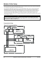
Magnitude™ Frictionless Centrifugal Chillers – Model WMC
41
VFD Line Harmonics
Despite their many benefits, care must be taken when applying VFDs due to the effect of line harmonics on the
building electric system. VFDs cause distortion of the AC line because they are nonlinear loads, that is, they
don't draw sinusoidal current from the line. They draw their current from only the peaks of the AC line, thereby
flattening the top of the voltage waveform. Some other nonlinear loads are electronic ballasts and
uninterruptible power supplies.
Line harmonics and their associated distortion can be critical to ac-drives for three reasons:
1. Current harmonics can cause additional heating to transformers, conductors, and switchgear.
2. Voltage harmonics upset the smooth voltage sinusoidal waveform.
3. High-frequency components of voltage distortion can interfere with signals transmitted on the AC
line for some control systems.
The harmonics of concern are the 5th, 7th, 11th, and 13th. Even harmonics, harmonics divisible by three, and high
magnitude harmonics are usually not a problem.
Current Harmonics
An increase in reactive impedance in front of the VFD helps reduce the harmonic currents. Reactive impedance
can be added in the following ways:
1.
2.
3.
4.
Mount the drive far from the source transformer.
Add line reactors. They are standard equipment on Magnitude chillers.
Use an isolation transformer.
Use a harmonic filter.
Voltage Harmonics
Voltage distortion is caused by the flow of harmonic currents through a source impedance. A reduction in
source impedance to the point of common coupling (PCC) will result in a reduction in voltage harmonics. This
can be done in the following ways:
1.
2.
3.
4.
Keep the PCC as far from the drives (close to the power source) as possible.
Increase the size (decrease the impedance) of the source transformer.
Increase the capacity (decrease the impedance) of the busway or cables from the source to the PCC.
Make sure that added reactance is "downstream" (closer to the VFD than the source) from the PCC.
Line Reactors
Five-percent line reactors are standard equipment on Magnitude chillers and located in each compressors power
panel. They are employed to improve the power factor by reducing the effects of harmonics.
Harmonic Filter
The harmonic filter is an option for field mounting and wiring outside of the power panel. It works in
conjunction with the line reactor to further minimize harmonic distortion. IEEE 519-1991 Standard defines
acceptable limits.
See the Magnitude certified drawings for harmonic filter dimensions and wiring information.
EMI (Electro Magnetic Interference) and RFI (Radio Frequency Interference) Filter
This filter is a factory-installed option. The terms EMI and RFI are often used interchangeably. EMI is actually
any frequency of electrical noise, whereas RFI is a specific subset of electrical noise on the EMI spectrum.
There are two types of EMI. Conducted EMI is unwanted high frequencies that ride on the AC wave form.
EMI
Radiated EMI is similar to an unwanted radio broadcast being emitted from the power lines. There are many
pieces of equipment that can generate EMI, variable frequency drives included. In the case of variable frequency
drives, the electrical noise produced is primarily contained in the switching edges of the pulse width modulation
(PWM) controller.
42
Magnitude™ Frictionless Centrifugal Chillers – Model WMC
IM 1029-2
As the technology of drives evolves, switching frequencies increase. These increases also increase the effective
edge frequencies produced, thereby increasing the amount of electrical noise.
The power line noise emissions associated with variable frequency and variable speed drives can cause
disturbances in nearby equipment. Typical disturbances include:
•
•
•
•
•
•
Dimmer and ballast instability
Lighting disturbances such as flashing
Poor radio reception
Poor television reception
Instability of control systems
Flow meter totalizing
•
•
•
•
•
Flow metering fluctuation
Computer system failures including loss of data
Thermostat control problems
Radar disruption
Sonar disruption
RFI
Three-phase filters are supplied as an option for factory mounting in the compressor power panels. They use a
combination of high frequency inductors and capacitors to reduce noise in the critical 150 kHz to 30 MHz
frequency range. The inductors act as open circuits and the capacitors act as short circuits at high frequencies
while allowing the lower power line frequencies to pass untouched. The filters assist with cost effective
compliance to Electro Magnetic Compatibility (EMC) directives, in a compact, efficient, light-weight design.
The high common mode and differential mode reduction in the critical 150kHz to 30MHz frequencies assures
that potential interference from AC drives is reduced or eliminated.
The filters are current-rated devices. In order to properly size a filter, it is necessary to know the operating
voltage and the input current rating of the drive. No derating or re-rating is necessary when applying the filter at
voltages that are less than or equal to the maximum voltage listed on the filter.
The IEEE 519-1991 Standard
The Institute of Electrical and Electronics Engineers (IEEE) has developed a standard that defines acceptable
limits of system current and voltage distortion. A simple form is available from McQuay International that
allows the system designer to determine compliance with IEEE 519-1991.
Line reactors, isolation transformers, or phase-shifting transformers can be required on some installations.
Fuses
All WMC chillers have power fuses upstream of the compressors. Models WMC 145S, 250D and 290D have
the fuses in the power panel. Models WMC 145D and 150D have them in the top of the compressor, accessible
by removing the compressor top cover.
Fuses are: Manufacturer: Littelfuse, Class: T, Amps: JLLS 175, Volts: 600V.
System Pumps
Operation of the chilled water pump can be to 1) cycle the pump with the unit, 2) operate continuously, or 3)
start automatically by a remote source.
The cooling tower pump must cycle with the compressor. The holding coil of the cooling tower pump motor
starter must be rated at 115 volts, 60 Hz, with a maximum volt-amperage rating of 100. A control relay is
required if the voltage-amperage rating is exceeded. See the Field Wiring Diagram on page 40 or in the cover of
control panel for proper connections.
All interlock contacts must be rated for no less than 10 inductive amps. The alarm circuit provided in the
control center utilizes 115-volts AC. The alarms must not draw more than 10-volt amperes.
IM 1029-2
Magnitude™ Frictionless Centrifugal Chillers – Model WMC
43
Multiple Chiller Setup
WMC units have their control components factory wired to an internal network (LAN) so that the components
can communicate with each other, within the chiller itself.
On multi-chiller Model WMC applications, up to four Model WMC chillers can be LAN interconnected by
field RS485 interconnecting wiring, with the addition of an accessory communication isolation board(s)
485OPDR (McQuay P/N 330276202) between each chiller (one less than the number of chillers connected),
and some MicroTech II control settings. The 485OPDR isolation board can be purchased with the unit or
separately, during or after chiller installation. N-1 boards are required. WMC chillers cannot be LAN
interconnected with WSC, WDC, WCC or WME centrifugal chillers. Interconnection should be made at startup
by the McQuay technician.
!
IMPORTANT NOTE
Chillers connected via pLAN connections MUST share the same software revision. WMC A-vintage models
may not be LAN interconnected to WMC B-vintage models. WMC chillers cannot be LAN interconnected with
WSC, WDC, WCC or WME centrifugal chillers.
Communication Setup
Figure 28, Communication Wiring
Chiller A
485
OPDR
C B A
P
P
J10 J11
UCM
Chiller C
A
P
485
B OPDR
C
P
J10 J11
UCM
Chiller B
C B A
44
Magnitude™ Frictionless Centrifugal Chillers – Model WMC
IM 1029-2
MicroTech II Operator Interface Touch Screen (OITS) Settings
Settings for any type of linked multiple compressor operation must be made to the MicroTech II controller.
Settings on a dual compressor unit are made in the factory prior to shipment, and verified in the field before
startup. Settings for multiple chillers are set in the field on the Operator Interface Touch Screen as follows:
Maximum Compressors ON – SETPOINTS - MODES screen, Selection #10 ‘= 2 for a dual, 4 for 2 duals, 3 for
three separate, single compressor chillers, etc. If all compressors in the system are to be available as normal
running compressors, then the value entered in #10 should equal the total number of compressors. If any
compressors are for standby and not operated in normal rotation, they should not be included in the compressor
count in Selection #10. The Max Comp ON setting can be made in only one touchscreen, the system will
observe the highest number set on all chillers-it is a global setting.
Sequence and Staging – SETPOINTS - MODES screen, Selection #12 & #14; #11 & #13. Sequence sets the
sequence in which compressors will start. Setting one or more compressors to “1” evokes the automatic lead/lag
feature and is the normal setting. The compressor with least starts will start first and the compressor with
maximum hours will stop first, and so on. Units with higher numbers will stage on in sequence.
The Modes setpoints will do several different types of operation (Normal, Efficiency, Standby, etc.) as described
in the operating manual.
The same Modes setting must be replicated on each chiller in the system.
Nominal Capacity – SETPOINTS - MOTOR screen, Selection #14. The setting is the compressor design tons.
Compressors on dual units are always of equal capacity.
Operating Sequence
For multiple-chiller, parallel operation, the MicroTech II controllers are tied together by a communications
network and stage and control compressor loading among the chillers. Each compressor, single or dual
compressor chiller, will stage on or off depending on the sequence number programmed into it. For example, if
all are set to “1”, the automatic lead/lag will be in effect.
When chiller #1 is fully loaded, the leaving chilled water temperature will rise slightly. When the Delta-T above
setpoint reaches the Staging Delta-T, the next chiller scheduled to start will receive a start signal and start its
pumps if they are set up to be controlled by the MicroTech II® controller. This procedure is repeated until all
chillers are running. The compressors will load-balance themselves.
If any of the chillers in the group are dual compressor, they will stage and load according to the staging
instructions.
See OM WMC (current edition) for a complete description of the various staging sequences available.
IM 1029-2
Magnitude™ Frictionless Centrifugal Chillers – Model WMC
45
Prestart System Checklist
Yes
No
N/A
Chilled Water
Piping complete .......................................................................................
Water system filled, vented ......................................................................
Pumps installed, (rotation checked), strainers cleaned .............................
Controls (3-way, face and bypass dampers, bypass valves, etc.) operable
Strainer installed at evaporator inlet.........................................................
Water system operated and flow balanced to meet unit design requirements
Condenser Water
Cooling tower flushed, filled and vented ................................................
Pumps installed, (rotation checked), strainers cleaned ............................
Strainer installed at condenser inlet..........................................................
Controls (3-way, bypass valves, etc.) operable .......................................
Water system operated and flow-balanced to meet unit requirements .....
Electrical
Power leads connected to the unit power panel(s) ..................................
All interlock wiring complete to control panel and complies with specifications
Pump starters and interlock wired ...........................................................
Cooling tower fans and controls wired ....................................................
Wiring complies with National Electrical Code and local codes ............
Condenser pump starting relay (CWR) installed and wired ....................
Miscellaneous
Relief valve piping complete ...................................................................
Thermometer wells, thermometers, gauges, control wells, controls, etc., installed
Minimum system load of 80% of machine capacity available for testing
and adjusting controls .............................................................................
Control wiring between multiple units, if applicable.........................................................
Note: This checklist must be completed and sent to the local McQuay Factory Service location two weeks prior
to start-up.
46
Magnitude™ Frictionless Centrifugal Chillers – Model WMC
IM 1029-2
Long Term Storage
This information applies to new units being stored waiting for startup or to existing units that may be
inoperative for an extended period of time.
The chiller must be stored in a dry location indoors and protected from any damage or sources of corrosion.
A McQuay service representative must perform an inspection and leak test of the unit on minimum quarterly
schedule, to be paid by the owner or contractor. McQuay International will not be responsible for any
refrigerant loss during the storage time or repairs to unit during period of storage, or while moving the unit
from original location to a storage facility and back to any new installation location.
The following tasks must be performed:
1.
As discussed above, the first and foremost task is to leak test the unit when it is in its final storage
location. If any leaks exist, repair them immediately. After the unit is stored, perform a periodic leak
test.
2.
It is possible that the unit could be bumped, hit or otherwise damaged while in storage; so in addition to
leak testing, a visual overall inspection should be done.
3.
If there is concern about the possibilities of damage and loss of charge during storage, the customer can
pay to have the charge removed and stored in recovery cylinders. If this is done, pressurize it to about
20 psi with nitrogen .Monitor and maintain the pressure. Install a pressure gauge that can easily be read
or tie in a remotely alarm that can be monitored if pressure reduces. This is desirable if the unit is stored
with refrigerant or with a nitrogen holding charge.
4.
If the unit has been shipped and not yet installed, keep it pumped down (as shipped from the factory)
with all refrigerant valves closed and capped.
5.
Clean and dry the unit and look for any chipped paint. Touch up as required to prevent rust.
6.
If the storage area is subject to a high humidity, consider a shrink wrap or water resistant covering of
some sort. Desiccants must be placed inside electrical panels and starters (mounted or shipped loose)
and be renewed as recommended by manufacturer. Remove the compressor top cover and place a
desiccant under the cover. Reinstall the cover and tighten all screws.
7.
The operator touchscreen monitor, which is shipped loose should be stored in a secure dry area. It is
subject to pilferage.
8.
Regardless of the temperature of the storage area, make sure all vessel tubes are drained and blown dry
of any water to prevent the minerals in standing water, plus oxygen present, causing tube pitting.
9.
Restart by a McQuay service technician will be required and paid to McQuay International by the
owner or contractor. It is prudent to take photos when the unit is stored to show that the conditions of
storage have been met. Also document all inspection reports and abnormal conditions found. If the unit
has been in operation, the run-time hours and number of starts must be documented prior to storage,
along with the date the unit was taken out of operation. The extended warranty coverage can be
suspended during the storage period-not to exceed 30 months. The remaining warranty time will restart
once unit is reinstalled and officially re-commissioned by McQuay Factory Service
IM 1029-2
Magnitude™ Frictionless Centrifugal Chillers – Model WMC
47
Operation
Operator Responsibilities
It is important that the operator become familiar with the equipment and the system before attempting operation.
During the initial startup of the chiller, the McQuay technician will be available to answer any questions and
instruct in the proper operating procedures.
It is recommended that the operator maintain an operating log for each individual chiller unit. In addition, a
separate maintenance log should be kept of the periodic maintenance and servicing activities.
Now that you have made an investment in modern, efficient Daikin McQuay equipment, its care and operation
should be a high priority. For training information on all Daikin McQuay HVAC products, please visit us at
www.daikinmcquay.com and click on Training, or phone 540-248-0711 and ask for the Training Department.
These sessions are structured to provide basic classroom instruction and include hands-on operating and
troubleshooting exercises.
Compressor Operation
The WMC compressors are two-stage. Suction gas enters the compressor through inlet guide vanes that can be
opened and closed to control refrigerant flow as the cooling load changes. The suction gas enters the first stage
impeller, is compressed, and travels through the vaned radial diffuser to the second stage impeller where
compression is completed. The gas travels to the condenser via the discharge volute, which converts any
remaining velocity pressure to static pressure.
Motor cooling is accomplished by utilizing the refrigerant effect of high-pressure liquid refrigerant from the
condenser expanded to a gas within the compressor. The refrigerant cools VFD heat sinks and the motor.
A five-axis magnetic bearing system supports the motor/compressor shaft, resisting radial and thrust forces. The
bearing control system uses shaft position feedback to continually adjust the bearing to keep the shaft in the
correct position. During coast down or in the event of a power failure, the compressor motor acts as a generator
and in conjunction with on-board capacitors powers the bearing support system. There is also a system to gently
de-levitate the shaft.
Many controls are mounted directly on the compressor where they monitor and control compressor operation.
These compressor controls are interfaced with the conventional MicroTech II controls to provide a complete
chiller control system.
System Water Volume
It is important to have adequate water volume in the system to provide an opportunity for the chiller to sense a
load change, adjust to the change, and stabilize. As the expected load change becomes more rapid, a greater
water volume is needed. The system water volume is the total amount of water in the evaporator, air handling
products and associated piping. If the water volume is too low, operational problems can occur including rapid
compressor cycling, rapid loading and unloading of compressors, erratic refrigerant flow in the chiller, improper
motor cooling, shortened equipment life and other undesirable consequences.
Some of the things the designer should consider when looking at water volume are the minimum cooling load,
the minimum chiller plant capacity during the low load period and the desired cycle time for the compressors.
Assuming that there are no sudden load changes and that the chiller plant has reasonable turndown, a rule of
thumb of “gallons of water volume equal to two to three times the chilled water gpm flow rate” is often used.
For process applications where the cooling load can change rapidly, additional system water volume is needed.
A process example would be a quenching tank. The load would be very stable until the hot material is immersed
in the water tank. Then, the load would increase drastically. For this type of application, system volume may
need to be increased.
48
Magnitude™ Frictionless Centrifugal Chillers – Model WMC
IM 1029-2
Since there are many other factors that can influence performance, systems may successfully operate below
these suggestions. However, as the water volume decreases below these suggestions, the possibility of problems
increases.
Variable Speed Pumping
Variable water flow involves inversely changing the water flow through the evaporator as the load changes.
Daikin McQuay chillers are designed for this duty provided that the rate of change in water flow is slow and the
minimum and maximum flow rates for the vessel, as shown in Figure 11 on page 18 are not exceeded.
The recommended maximum change in water flow is 10 percent of the allowable flow change per minute. Flow
is usually not reduced below 50 percent of design flow (provided vessel minimum flow rates are not exceeded).
For example, a 150-ton chiller might have chilled water flow of 360 gpm, reduced to 50 percent, would be 180
gpm. However, the minimum flow rate is 216 gpm, so the flow change would be 360 gpm minus 216 gpm, or
144 gpm. This means that the allowable flow rate change would be 10 percent of 144 or 14.4 gpm per minute.
MicroTech II Control
Figure 29, MicroTech II Control Panel
Magnitude chillers are equipped with the McQuay MicroTech II control system consisting of:
•
Operator interface touchscreen (OITS) with a 15-inch Super VGA color screen.
•
Control Panel containing the MicroTech II controller interfacing with the compressor-mounted controls,
the PC controlling the OITS and various switches and field connection terminals.
Operating instructions for the MicroTech II controller are contained in Operating Manual OM 1008.
Use with On-Site Generators
Magnitude chillers (excluding WMC 145S) have their total tonnage divided between two compressors that start
sequentially and they are operated with variable frequency drives. These features make Magnitude chillers
especially appropriate for use in applications where they may be required to run with on-site electrical
generators. This is particularly true when the generators are used for temporary power when the utility power is
lost.
Generator Sizing: Gas and diesel generators are sensitive to the compressor’s locked-rotor characteristics when
the chillers start up. Use the electrical data supplied with the performance output sheet, obtained from the Daikin
McQuay sales office, for generator sizing purposes. The chiller data sheet will show the RLA, which is for both
compressors. Refer to Electrical Data to determine the LRA, based on the RLA. It is important to size the
generator to handle the LRA at start up.
Starting/Stopping Procedure: The stopping of the chiller in the event of a power failure should be uneventful.
The chiller will sense a loss of voltage and the compressors will stop, coasting down using power generated
from their dynamic braking to maintain the bearing magnetic field. The stop signal will initiate a three-minute
stop-to-start timer, effectively preventing compressor restart for three minutes. The timer is adjustable from three
to fifteen minutes; the recommended default value is three minutes. This interval allows the generator sufficient
time to get up to speed and stabilize. The chiller will restart automatically when the start-to-start timer expires.
IM 1029-2
Magnitude™ Frictionless Centrifugal Chillers – Model WMC
49
Transfer Back to Grid Power: Proper transfer from stand-by generator power back to grid power is essential to
avoid compressor damage.
!
WARNING
Stop the chiller before transferring supply power from the generator back to the utility power grid. Transferring
power while the chiller is running can cause severe compressor damage.
The procedure for reconnecting power from the generator back to the utility grid is shown below. These
procedures are not peculiar to Daikin McQuay units only, but should be observed for any chiller manufacturer.
1. Set the generator to always run five minutes longer than the unit start-to-start timer, which could be set from
15 to 60 minutes. The actual setting can be viewed on the operator interface panel on the Setpoint/Timer
screen.
2. Configure the transfer switch, provided with the generator, to automatically shut down the chiller before
transfer is made. The automatic shut-off function can be accomplished through a BAS interface or with the
“remote on/off” wiring connection shown in the field wiring diagram. A start signal can be given anytime
after the stop signal since the three-minute start-to-start timer will be in effect.
Chiller Control Power: For proper operation on standby power, the chiller control power must remain as
factory-wired from a unit-mounted transformer. Do not supply chiller control power from an external power
source because the chiller may not sense a loss of power and do a normal shutdown sequence.
Building Automation Systems
All MicroTech II controllers with Open Choices™ are capable of BAS communications, providing easy
integration and comprehensive monitoring, control, and two-way data exchange with open standard protocols
such as LonTalk, Modbus or BACnet.
Daikin McQuay unit controllers strictly conform to the interoperability guidelines of the LONMARK
Interoperability Association and BACnet International. They have received LONMARK certification with
optional LONWORKS communication module.
Protocol Options
•
•
•
BACnet MS/TP
BACnet IP
BACnet Ethernet
•
•
LONWORKS (FTT-10A)
Modbus RTU
The BAS communication module can be ordered with a chiller and factory-mounted or can be field-mounted at
any time after the chiller unit is installed.
Table 16, Typical Data Point Availability
Active Setpoint
Actual Capacity
Capacity Limit Output
Capacity Limit Setpoint
Chiller Enable
Chiller Limited
Chiller Local/Remote
Chiller Mode Output
Chiller Mode Setpoint
Chiller On/Off
Chiller Status
Compressor Discharge Temp
Compressor Percent RLA
Compressor Run Hours
Compressor Select
Compressor Starts
Compressor Suction Line
Temp
Typical Data Points1 (W = Write, R = Read)
R
Cond EWT
R
Evap Water Pump Status
R
Cond Flow Switch Status
R
Liquid Line Refrigerant Pressure
R
Cond LWT
R
Liquid Line Refrigerant Temp
W
Cond Pump Run Hours
R
Maximum Send Time
W
Cond Refrigerant Pressure
R
Minimum Send Time
Cond Sat. Refrigerant
R
R
Network Clear Alarm
Temp
R
Cond Water Pump Status
R
Pump Select
R
Cool Setpoint
W
Run Enabled
W
Current Alarm
R
R
Default Values
W
R
Evap EWT
R
R
Evap Flow Switch Status
R
R
Evap LWT for Unit
R
R
Evap LWT for Compressor
R
W
Evap Pump Run Hours
R
R
Evap Refrigerant Pressure
R
Evap Sat. Refrigerant
R
R
Temp
R
R
R
W
W
W
W
R
Note: Data points available are dependent upon options selected.
50
Magnitude™ Frictionless Centrifugal Chillers – Model WMC
IM 1029-2
Connection to Chiller
Connection to the chiller for all BAS protocols will be at the unit controller. An interface card, depending on
the protocol being used, will have been factory installed in the unit controller if so ordered, or it can be field
installed.
Protocols Supported
Table 17, Standard Protocol Data
Protocol
Physical Layer
Data Rate
Controller
Other
BACnet/IP
Ethernet 10 Base-T
10 Megabits/sec
Color graphics SBC
Reference ED 15057: BACnet PICS
BACnet MSTP
RS485
(TBD)
pCO Unit Controller
LonTalk
FTT-10A
78kbits/sec
pCO Unit Controller
Reference ED 15057: BACnet PICS
LONMARK Chiller Functional
Profile
Modbus RTU
RS-485
(TBD)
pCO Unit Controller
NOTE: For additional information on the protocol data available through the BACnet or LonTalk
communications modules, reference McQuay ED 15062, MicroTech II Chiller Unit Controller Protocol
Information.
Modbus - When selected, the ident number and baud can also be changed to suit the application.
LONWORKS – When selected, the ident number and baud rate setpoints are not available. Baud rate is locked at
4800.
BACnet – When selected, the ident number and baud rate setpoints are not available. Baud rate is locked at
19200.
If an interface module was ordered, one of the following BAS interface installation manuals was shipped with
the unit. If necessary, contact your local Daikin McQuay sales office for a replacement or obtain from
www.daikinmcquay.com.
Modbus: IM 743
LonWorks: IM 735
BACnet Ethernet or IP: IM 837
BACnet MS/TP: IM 906
IM 1029-2
Magnitude™ Frictionless Centrifugal Chillers – Model WMC
51
52
Magnitude™ Frictionless Centrifugal Chillers – Model WMC
IM 1029-2
Daikin McQuay Learning Institute
Now that you have made an investment in modern, efficient Daikin McQuay equipment, its care should be a high
priority. For training information on all Daikin McQuay HVAC products, please visit us at
www.daikinmcquay.com/Training, or call 540-248-9646 to speak to the Training Department.
Warranty
All Daikin McQuay equipment is sold pursuant to McQuay International standard terms and conditions of sale,
including Limited Product Warranty. Consult your local Daikin McQuay Representative for warranty details. To
find your local Daikin McQuay Representative, go to www.daikinmcquay.com.
This document contains the most current product information as of this printing. For the most up-to-date product
information, please go to www.daikinmcquay.com.
© McQuay International • www.daikinmcquay • (800) 432-1342
IM 1029-2 (10/12)