1
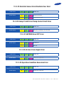
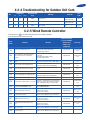
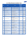
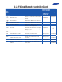
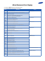
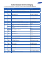
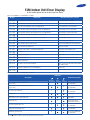
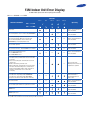
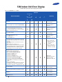
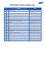
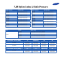
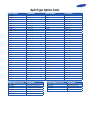
Samsung Error Code Booklet Introduction Welcome to the new Samsung Error Code Booklet, for our repair network. This booklet has been designed to offer on site assistance for fault code analysis across the whole Samsung Air Conditioning range. Split Systems AC Cassette System AC Ducted System AC Free Joint Multi AC Please use this book when attending Service Calls as it will assist you with the next steps on how to diagnose the system problem. Should you need any further assistance please call Technical Support on 1300 887 660 Option 1. Split Type Error Codes 12-2-1 Communication Error Indoor Display Communication error Outdoor Display 1 min. Time out Comm. Abnormal Communication 12-2-2 Indoor Temperature Sensor Error Indoor Display Indoor room temp sensor error 12-2-3 Indoor Heat Exchanger Temperature Sensor Error Indoor Display Indoor Eva-in temp sensor error 12-2-5 DC-Link Voltage Sensor Error Indoor Display Outdoor error Outdoor Display DC-link voltage sensor error 12-2-6 Indoor Fan Motor Speed Detecting Error (BLDC Fan) Indoor Display Indoor fan error 12-2-7 Outdoor Temtperature Sensor Indoor Display Outdoor error Outdoor Display Outdoor temperature sensor error LED 1 = Operation / LED 2 = Timer / LED 3 = S-Plasma Ion : Off : Blink : On 12-2-8 Outdoor Coil Temperature Sensor Error Indoor Display Outdoor error Outdoor Display Outdoor coil temperature sensor error 12-2-9 Outdoor Discharge Temperature Sensor Error Indoor Display Outdoor error Outdoor Display Outdoor discharge temperature sensor error 12-2-10 Outdoor Discharge Over Temperature Error Indoor Display Outdoor error Outdoor Display Outdoor discharge over temperature error 12-2-11 Outdoor Fan Motor Error Indoor Display Outdoor error Outdoor Display Outdoor fan error 12-2-12 Compressor Starting Error Indoor Display Outdoor error Outdoor Display Comp starting error LED 1 = Operation / LED 2 = Timer / LED 3 = S-Plasma Ion : Off : Blink : On 12-2-13 Compressor Wire Missing Error/Rotation Error Indoor Display Outdoor error Outdoor Display Compressor wire missing error/rotation error 12-2-14 O.C.(Over Current) Error Indoor Display Outdoor error Outdoor Display Comp starting error 12-2-16 DC-Link Voltage Under/Over Error, Over Voltage Protection Error/PFC Over Load Indoor Display Outdoor error DC-link voltage under/over error Over voltage protection error PFC overload Outdoor Display 12-2-17 I-Trip Error, PFC Over Current Indoor Display Outdoor error Outdoor Display I-trip error, PFC over current 12-2-18 Current Sensor Error/Input Current Sensor Error Indoor Display Outdoor error Outdoor Display Current sensor error/Input current sensor error LED 1 = Operation / LED 2 = Timer / LED 3 = S-Plasma Ion : Off : Blink : On 12-2-19 Heatsink Sensor Error/Heatsink Over Heat Indoor Display Outdoor error Outdoor Display Heatsink sensor error Heatsink over heat error 12-2-20 Comp V Limit Error/Comp Current Limit Error Indoor Display Outdoor error Outdoor Display Comp Vlimit error/Comp current limit error 12-2-21 EEPROM Error/OTP Error Indoor Display Outdoor error Outdoor Display EEPROM error OTP error 12-2-22 AC Zero Cross Signal Error Indoor Display Outdoor error Outdoor Display AC zero cross signal error 12-2-23 Operation Condition Secession Error Indoor Display Outdoor error Outdoor Display AC zero cross signal error LED 1 = Operation / LED 2 = Timer / LED 3 = S-Plasma Ion : Off : Blink : On 12-2-24 Capacity Miss Match Error Indoor Display Outdoor error Outdoor Display Capacity miss match error 12-2-25 Gas Leak Error Indoor Display Outdoor error Outdoor Display Gas leak error 12-2-26 IPM Over Current (O.C) Outdoor Display IPM Over Current (O.C) 12-2-27 Option Code Error Indoor Display All LED’s are flashing on the indoor unit LED 1 = Operation / LED 2 = Timer / LED 3 = S-Plasma Ion : Off : Blink : On Cassette Error Codes 4-2-1 Four directions cassette type Error mode Product operation with error Cause Operation Outdoor heat exchanger fan Indoor heat exchanger fan Outdoor Display Timer Filter X X X Power reset - Operationoff Operationoff Operationoff - X X Error of room temperature sensor in the indoor unit (open/short) - Check indoor temperature connection. - Check indoor temperature sensor’s resistance value to see if it’s short/open Operationoff Operationoff Operationoff page 4-17 X X Error of heat exchanger IN/OUT sensor in the indoor unit (Open/Short) - Check EVA IN/OUT sensor connection. - Check EVA IN/OUT sensor’s resistance value to see if it’s short/open. Operationoff Operationoff Operationoff page 4-18 X Error of fan motor in the Indoor unit - Check the connection of motor connector. - Check the speed of the motor fan Operationoff Operationoff Operationoff page 4-19 X Error of the outdoor temperature sensor Error of the condenser temperature sensor Error of the discharge temperature sensor - Check indoor temperature sensor connection. - Check indoor temperature sensor’s resistance value to see if it’s short/open. Operationoff Operationoff Operationoff - X No communication for 2 minutes between indoor and outdoor unit (communication error for more than 2 minutes) - Check connection between indoor and outdoor heat exchanges’ communication cables Operationoff Operationoff Operationoff page 4-20 Error of outdoor unit - Check error occurred with outdoor heat exchanger Operationoff Operationoff Operationoff - Detection of the float switch - Check float switch connection. - Check whether the drain has been filled with water. Operationoff Operationoff Operationoff page 4-21 EEPROM error - Check if there is damage with EEPROM component. Operationoff Operationoff Operationoff page 4-22 EEPROM option error - Check the indoor model to set the options. - Inspection for match between indoor and outdoor machine models. Operationoff Operationoff Operationoff - X X X X X Outdoor heat exchanger compressor Defrost X X Measures X X : On : Blink X : Off 4-2-4 Troubleshooting for Outdoor Unit If an error occurs during the operation, it is displayed on the outdoor unit PCB LED, both MAIN PCB and INVERTER PCB. LED Display Red Green Yellow Displayed PCB Assy Meaning Remarks - MAIN/INVERTER Normal operation (MAIN : IndoornOutdoor : Green ON) (INVERTER : MAIN PCBnINVERTER PCB : Green ON) 1 MAIN Refer to Service Manual for more information Check indoor quantity setting in outdoor (Refer to page 17.) 2 MAIN/INVERTER Abnormal state, no communication between Indoor and Outdoor Main PCB Check electrical connection and setting 1min. Time out of communication error (MainnInverter) Check electrical connection and setting Check Outdoor sensor Open/Short Check Cond. sensor Open/Short Check Discharge sensor Open/Short Check OLP sensor Open/Short No. Unit quantity miss matching between indoor and outdoor. 3 MAIN/INVERTER 4 MAIN Outdoor temp sensor error 5 MAIN Cond. temp sensor error 6 MAIN Discharge temp sensor error 7 MAIN OLP Sensor Error 8 MAIN Detection of Outdoor Freezing when Comp. Stop 9 MAIN Protection of Outdoor Overload when Comp. Stop 10 MAIN Discharge temperature of a compressor in an outdoor unit is overheated. 11 MAIN Heating operation is not available since the outdoor air temperature is over 30°C. Cooling operation is not available since the outdoor air temperature is lower than -5°C. 12 MAIN/INVERTER Outdoor unit BLDC Fan 1 or Fan 2 error 13 MAIN/INVERTER Comp. Starting error 14 MAIN Primary Current Trip error 15 MAIN Over current trip / PFC over current error 16 MAIN/INVERTER IPM(IGBT Module) Over Current(O.C) 17 MAIN/INVERTER Comp. Over load error 18 MAIN/INVERTER DC-Link voltage under/over error 19 MAIN/INVERTER Comp. wire missing error 20 MAIN/INVERTER Current sensor error 21 MAIN Outdoor EEPROM error 22 MAIN/INVERTER IPM(IGBT Module) or PFCM Temperature sensor Error 23 MAIN/INVERTER PFC Overload Error 24 MAIN/INVERTER IPM is over heated. Check Outdoor Cond. Check Comp. when it start Refer to Service Manual for more information Error Code - E201 E202 E203 E221 E231 E251 E320 E403 E404 E416 Heating E440 Cooling E441 FAN1 error FAN2 error Refer to Service Manual for more information Refer to Service Manual for more information E458 E475 Check OLP sensor E463 Refer to Service Manual for more information Refer to Service Manual for more information Check AC Power or DC-Link voltage Check Comp. wire Check Outdoor Inverter PBA Check Outdoor EEPROM date Check Outdoor Inverter PBA Check Outdoor Inverter PBA Check Outdoor Inverter PBA E461 E462 E464 E465 E466 E467 E468 E471 E474 E484 E500 : Off : Blink : On 4-2-4 Troubleshooting for Outdoor Unit Cont. LED Display Red Green Yellow Displayed PCB Assy 25 MAIN 26 MAIN Capacity miss match between indoor and outdoor MAIN Option code miss matching among the indoors (only for DPM) No. 27 Meaning Error Code Remarks GAS Leak error Check indoor and outdoor unit model Check indoor and outdoor unit model Check indoor option code E554 E556 E557 : Off : Blink : On 4-2-5 Wired Remote Controller - If an error occurs, ( ) icon will be displayed on the wired remote controller. - Press the Test button to see the error code. Error mode Product operation in error condition Contents Measure Outdoor unit/ Compressor/ Indoor unit Error type 101 Indoor unit communication error Check the communication cable of indoor unit. Check the DC output voltage at the communication terminal Operation Off Communication error 102 Indoor unit/outdoor unit communication time-out error: errors in more than 6 packets Check the outdoor communication cable connection. Check DC output voltage and the communication terminal Operation Off Communication error 121 Indoor temperature sensor (open/short error) Check indoor unit room temperature sensor. Check indoor unit PCB connector CN41 (White) Operation Off Indoor sensor error 122 Indoor unit Eva In sensor (Open/Short) Check indoor unit pipe sensor. Check indoor PCB connector CN41(White) Operation Off Indoor sensor error 128 Indoor unit Eva In sensor disconnection Check the disconnection of indoor unit pipe sensor Operation Off Indoor sensor error 129 Indoor unit EVA Out Sensor Separation Refer to Service Manual for more information 153 Indoor floating switch secondary detection Check indoor unit float sensor. Check indoor PCB connector CN5 (black) Operation Off Self diagnostic error 201 Unit Miss Match Indoor / Outdoor Refer to Service Manual for more information 202 Indoor/outdoor communication error (1 min) Check the communication connection between indoor and outdoor units. Check the power line and communication cable connection status Operation Off Communication error 203 Communication error between indoor/ outdoor INVnMAIN MICOM (1 min) Check MAIN MICOM Check INVERTER MICOM - Communication error 221 Outdoor temperature sensor error Check sensor connection status Check sensor location Check sensor resistance Operation Off Outdoor sensor error 231 Cond Temp Sensor Error Refer to Service Manual for more information 237 COND temperature sensor error Check sensor connection status Check sensor location Check sensor resistance Operation Off Outdoor sensor error 251 [Inverter] Emission temperature sensor error Check sensor connection status Check sensor location Check sensor resistance Operation Off Outdoor sensor error 320 OPL Sensor Error Refer to Service Manual for more information 403 Detection of Outdoor Freezing When Compressor Stop Refer to Service Manual for more information 4-2-5 Wired Remote Controller Cont. Product operation in error condition Error mode Contents Measure Outdoor unit/ Compressor/ Indoor unit Error type 404 Protection of Outdoor Overload When Compressor Stop Refer to Service Manual for more information 419 EEV Open Error Refer to Service Manual for more information 422 EVV Close Error Refer to Service Manual for more information 425 Power Cable Miss Connection Refer to Service Manual for more information 440 Heating operation blocked Check the operation setting state Check temperature sensor Operation Off Self diagnostic error 441 Cooling operation blocked Check the operation setting state Check temperature sensor Operation Off Self diagnostic error 461 [Inverter] Compressor startup error Check the compressor connection status Check the resistance between difference phases of the compressor Operation Off Outdoor unit protection control error 462 [Inverter] Total current error/PFC over current error Check the input power Check the coolant charging status Check the normal operation of outdoor fan Operation Off Outdoor unit protection control error 463 OLP Heat Sink Sensor Error Refer to Service Manual for more information 464 [Inverter] IPM over current error Check coolant charging Check the compressor connection status and normal operation Check the obstacles around the indoor and outdoor units Check whether the outdoor unit service valve is open Check whether the indoor/outdoor installation pipe/ wiring are correct Operation Off Outdoor unit protection control error 465 Compressor V limit error Check the compressor connection status Check the resistance between difference phases of the compressor Operation Off Outdoor unit protection control error 466 DC LINK over/low voltage error Check input power Check AC power connection Restart in 3 minutes Outdoor unit protection control error 467 [Inverter] Compressor rotation error Check the compressor connection status Check the resistance between difference phases of the compressor Operation Off Outdoor unit protection control error 468 [Inverter] Current sensor error Check EEPROM DATA Check the normal operation of PCB Operation Off Outdoor unit protection control error 469 [Inverter] DC LINK voltage sensor error Check the input power connection Check the status of RY21 and R200 in the INVERTER PCB Operation Off Outdoor unit Protection control error 471 [Inverter] OTP error Check EEPROM DATA Check the normal operation of PCB Operation Off Outdoor unit protection control error 472 AC ZERO CROSSING SIGNAL OUT error Check the input power status Operation Off Outdoor unit protection control error 473 Compressor LOCK error Check the compressor connection status Check the resistance between difference phases of the compressor Operation Off Outdoor unit protection control error 474 Heat Sink Sensor Error Refer to Service Manual for more information 4-2-5 Wired Remote Controller Cont. Product operation in error condition Error mode Contents Measure 475 Outdoor fan 2 error Check the input power connection status Check the connection status of the motor and the outdoor unit PCB Check the indoor/outdoor unit fuse 484 PFC Overload Error Refer to Service Manual for more information 485 Input Current Sensor Error Refer to Service Manual for more information 500 Heat Sink Over Heat Error Refer to Service Manual for more information 554 Gas leak error Check the coolant charging status Check the indoor EVA sensor Check if the outdoor unit service value is open Check that the indoor/outdoor installation pipe/ wiring are correct 557 Option Code Miss Match Indoor Units Refer to Service Manual for more information 601 Communication error between the indoor unit and wired remote controller 602 Outdoor unit/ Compressor/ Indoor unit Error type Operation Off Self diagnostic error Operation Off Self diagnostic error Check the connection wire between the indoor unit and the wired remote controller Normal operation Wired remote controller error Communication error between the Master and Slave wired remote controllers Check the option switch for defining the Master and Slave (only one Master and one Slave can exist) Normal operation Wired remote controller error 606 COM1/COM2 cross installation error Check that wired remote controller is connected to the COM2 terminal of the indoor unit Normal operation Wired remote controller error EA Wired remote controller COM2 option setting error Check that Com1, Com2 setting DIP switch is set to Com2 Normal operation Wired remote controller error Wired Remocon Error Display - If an error occurs, is displayed on the wired remote controller. - If you would like to see an error code, press the Test button. Display Explanation 101 Indoor unit Communication Error 102 Indoor/Outdoor unit Communication Time Out Error 60 Packet Over data 201 Indoor unit is not connected 203 Communication Error between Outdoor Main and Inverter Micom (Occurred after 1 minute detection in Main and Inverter) 121 Indoor Temp. Sensor(Open/Short Error) 122 Indoor Unit Eva in Sensor(Open/Short Error) 128 Indoor Unit Eva in Sensor Separation 221 Outdoor Temp. Sensor Error(Open/Short Error) 237 COND Temp. Sensor Error(Open/Short Error) 251 Inverter Compressor Discharge Temp. sensor Error(Open/Short Error) 425 Power cable miss connection error 153 Indoor Float Switch 2nd Detection 460 Outdoor unit - indoor unit communication wire miss connection (Connected to Power terminal) 554 Outdoor unit refrigerant Full leakage(Gas leak) 458 Outdoor Fan 1 Error 475 Outdoor Fan 2 Error 416 Discharge over temperature 461 [Inverter] Compressor starting error 462 Primary Current Over Trip error 464 [Inverter]IPM Over Current(O.C) 467 [Inverter] Compressor Rotation error 468 [Inverter] Current Sensor error 469 [Inverter] DC LINK Sensor error 471 [Inverter] EEPROM Read/Write Error 474 [Inverter] Heatsink temperature over Error 556 Outdoor unit Capacity Setup option error 601 Communication error between Indoor unit and wired remote control 602 Communication error between Master and Slave wired remote control 606 COM1/COM2 Cross-installed error EA Error of setting option for wired remote control COM2 Remark Communication Error Indoor Sensor Error Outdoor Sensor Error Self Diagnosis Error Outdoor Unit Protection Control Error Outdoor Unit Protection Control Error Wired remote control error Ducted Outdoor Unit Error Display - If an error occurs during the operation, it is displayed on the outdoor unit PCB LED, both MAIN PCB and INVERTER PCB. No. 1 Error Code E201 Meaning Remarks Unit quantity miss matching between indoor and outdoor. Check indoor quantity setting in outdoor (Refer to page 17.) 2 E202 Abnormal state, no communication between Indoor and Outdoor Main PCB Check electrical connection and setting 3 E203 1min. Time out of communcation error(MainnInverter) Check electrical connection and setting 4 E221 Outdoor temp sensor error Check Outdoor sensor Open/Short 5 E231 Cond. temp sensor error Check Cond. sensor Open/Short 6 E251 Discharge temp sensor error Check Discharge sensor Open/Short 7 E320 OLP Sensor Error Check OLP sensor Open/Short 8 E403 Detection of Outdoor Freezing when Comp. Stop Check Outdoor Cond. 9 E404 Protection of Outdoor Overload when Comp. Stop Check Comp. when it start E416 Discharge temperature of a compressor in an outdoor unit is overheated. Refer to Service Manual for more information E440 Heating operation is not available since the outdoor air temperature is over 30°C. Heating E441 Cooling operation is not available since the outdoor air temperature is lower than -5°C. Cooling 10 11 E458 12 FAN1 error Outdoor unit BLDC Fan 1 or Fan 2 error E475 FAN2 error 13 E461 Comp. Starting error Refer to Service Manual for more information 14 E462 Primary Current Trip error Refer to Service Manual for more information 15 E463 Over current trip / PFC over current error Check OLP sensor 16 E464 IPM(IGBT Module) Over Current(O.C) Refer to Service Manual for more information 17 E465 Comp. Over load error Refer to Service Manual for more information 18 E466 DC-Link voltage under/over error Check AC Power or DC-Link voltage 19 E467 Comp. wire missing error Check Comp. wire 20 E468 Current sensor error Check Outdoor Inverter PBA 21 E471 Outdoor EEPROM error Check Outdoor EEPROM date 22 E474 IPM(IGBT Module) or PFCM Temperature sensor Error Check Outdoor Inverter PBA 23 E484 PFC Overload Error Check Outdoor Inverter PBA 24 E500 IPM is over heated. Check Outdoor Inverter PBA 25 E554 GAS Leak error Check indoor and outdoor unit model 26 E556 Capacity miss match between indoor and outdoor Check indoor and outdoor unit model FJM Indoor Unit Error Display for AQV models please refer to the Split Type Error Codes MH h h h FVEA/MH h h h FBEA/MH h h h FAEA Display Explanation Main Checking Point / Remark E1 n 01 Communication error (unable to receive data) Communication cable connection E1 n 02 Communication error (outdoor cannot communicate) Another indoor unit or indoor PCB E1 n 21 Indoor unit room temperature sensor error (Open/Short) Room temperature sensor, indoor PCB E1 n 22 Indoor unit heat exchanger in temperature sensor error (Open/Short) Heat exchanger in sensor, indoor PCB E1 n 23 Indoor unit heat exchanger out temperature sensor error (Open/Short) Heat exchanger out sensor, indoor PCB E1 n 28 Indoor unit heat exchanger in temperature sensor detached Heat exchanger in sensor E1 n 29 Indoor unit heat exchanger out temperature sensor detached Heat exchanger out sensor E1 n 30 Indoor unit heat exchanger in & out temperature sensor detached Heat exchanger in & out sensor E1 n 53 Indoor unit float switch second detection Refer to Service Manual for more information E1 n 54 Indoor unit fan motor malfunction Fan motor and cable E1 n 61 More than 2 indoor units cool and heat simultaneously Another indoor unit operation mode E1 n 62 EEPROM error Indoor PCB E1 n 63 Option code setting error Option code E1 n 85 Cable miss-wiring Cable connection (Indoor & Outdoor unit) E1 n 86 MPI error malfunction MPI E2 n 01 The number of indoor unit mismatched Cable connection (another indoor unit & outdoor unit), SW01(outdoor) E2 n 51 Compressor discharge sensor error(Short/Open) Outdoor unit E2 n 59 Outdoor unit error Outdoor unit (Error code) MH h h h FVEA/MH h h h FBEA/MH h h h FAE A Indicators Description Main Checking Point Operation Indoor unit room temperature sensor error (open or short) Timer Indoor unit heat exchanger temperature sensor error (open or short) Indoor fan motor malfunction Turbo Refer to Service Manual for more information Refer to Service Manual for more information Refer to Service Manual for more information EEPROM error Option Setting Option error (option wasn’t set up or option data error) Option Setting Outdoor unit error Indoor unit communication error Simultaneous operation error : On, : Flickering, X: OFF u If you turn off the air conditioner when the LED is flickering, the LED is also turned off. Refer to Service Manual for more information X Outdoor unit communication error X Remote Control on/off Outdoor Unit Power Reset Refer to Service Manual for more information Refer to Service Manual for more information FJM Indoor Unit Error Display for AQV models please refer to the Split Type Error Codes MH h h h FSEA/MH h h h FMEA Indicators Abnormal Conditions Green Red Yellow Green Orange X X X X Refer to Service Manual for more information X X X Refer to Service Manual for more information X X X Refer to Service Manual for more information X X Refer to Service Manual for more information X X X Refer to Service Manual for more information X X X Refer to Service Manual for more information X Error of indoor unit: Displayed on the indoor unit regardless of operation MH h h h FSEA Operating MH h h h FMEA Power reset Error of temperature sensor in indoor unit (OPEN/SHORT) X Error of heat exchanger sensor in indoor unit Error of heat exchanger OUT sensor in indoor unit Error of outlet temperature sensor in indoor unit (OPEN/SHORT): For heat pump models only Error of mixed operation X Error of indoor fan motor : Below 450RPM for 15 minutes X Error of outdoor temperature sensor Error of CONDENSER sensor Error of DISCHARGE sensor 1. No communication for 2 minutes between indoor unit and outdoor unit (communication error for more than 2 minutes) 2. Indoor unit receiving the communication error from outdoor unit 3. Outdoor unit tracking 3 minutes error 4. When sending the communication error from outdoor unit due to the mismatching of the communication numbers and installed numbers after completion of tracking (communication error for more than 2 minutes) X X 1. 2nd detection of refrigerant completely leak 2. 2nd detection of high temperature CONDENSER 3. 2nd detection of high temperature DISCHARGE 4. Compressor down due to 6th detection of freezing X X Error of float switch X X Error of setting option switches for optional accessories X X EEPROM error EEPROM option error : On, : Flickering, X: OFF u If you turn off the air conditioner when the LED is flickering, the LED is also turned off. X Displayed on appropriate indoor unit which is operating Displayed on outdoor unit Refer to Service Manual for more information X Refer to Service Manual for more information X X Refer to Service Manual for more information Refer to Service Manual for more information FJM Indoor Unit Error Display for AQV models please refer to the Split Type Error Codes MH h h h FJEA LED lamp display Abnormal Conditions Remarks White X Refer to Service Manual for more information Power reset X X Error of temperature sensor in the indoor unit (Open/ Short) X X X Error of heat exchanger sensor in the indoor unit X X X Refer to Service Manual for more information Error of the outdoor temperature sensor Error of the condensor temperature sensor Error of the discharge temperature sensor X X Refer to Service Manual for more information X X 1. Indoor unit error (Display is unrelated with operation) 2. Outdoor unit error (Display is unrelated with operation) X X Indoor motor fan error X Refer to Service Manual for more information X Refer to Service Manual for more information X 1. No communication between indoor and outdoor unit for 2 minutes 2. Error on the communication received from outdoor unit 3. Outdoor unit tracking time out (3 minutes) 4. Number of installation does not match after tracking X Indoor fan motor is non-operative Indoor fan motor is operating slowly Indoor fan motor is operates at an excessive speed X X Simultaneous cooling/heating operation error (Multi model only) X X [Self diagnosis ]Power voltage detection between indoor and outdoor unit communication cable [Self diagnosis ]Outdoor unit refrigerant leakage(Gas leak) [Self diagnosis ]Outdoor fan restriction error [Inverter ]Inverter compressor operation failure [Inverter ] DC peak error [Inverter ]DC Link voltage 150V or less,410V or more [Inverter ] Compressor rotation error [Inverter ]Electric current error [Inverter ]DC Link sensor error [Inverter ]EEPROM READ/WRITE error [Inverter ]Inverter zerocrossing error Setting the outdoor unit capacity option error EEPROM error X X X X Refer to Service Manual for more information X Refer to Service Manual for more information EEPROM option error MPI no feedback error : On, : Flickering, X: OFF u If you turn off the air conditioner when the LED is flickering, the LED is also turned off. Refer to Service Manual for more information X X X X Refer to Service Manual for more information FJM Indoor Unit Error Display for AQV models please refer to the Split Type Error Codes NJ h h h LHXEA/MH h h h FUEA Indicators Concealed Type Abnormal Conditions Power reset Error of temperature sensor in indoor unit(OPEN/SHORT) X X Refer to Service Manual for more information X X X Displayed on appropriate indoor unit which is operating X X X Displayed on appropriate indoor unit which is operating X X Refer to Service Manual for more information X X Displayed on appropriate indoor unit which is operating Displayed on outdoor unit X 1. Error of indoor unit : Displayed on the indoor unit regardless of operation 2. Error of outdoor unit : Displayed on the indoor unit which is operating X X Error of heat exchanger sensor in indoor unit Error of heat exchanger OUT sensor in indoor unit Error of outlet temperature sensor in indoor unit (OPEN / SHORT): For heat pump models only Error of mixed operation X Error of outdoor temperature sensor Error of COND sensor Error of DISCHARGE sensor X 1. No communication for 2 minutes between indoor unit and outdoor unit (communication error for more than 2 minutes) 2. Indoor unit receiving the communication error from outdoor unit 3. Outdoor unit tracking 3 minutes error 4. When sending the communication error from outdoor unit the mismatching of the communication numbers and installed numbers after completion of tracking. (communication error for more than 2 minutes) X X Self-diagnostic error (including the indoor unit not detected) 1. Error of electronic expansion valve close 2. Error of electronic expansion valve open 3. Breakaway of EVA OUT sensor 4. Breakaway of EVA IN sensor 5. Breakaway of COND MID sensor 6. 2nd detection of refrigerant completely leak 7. 2nd detection of high temperature COND 8. 2nd detection of high temperature DISCHARGE 9. COMP DOWN due to 2nd detection of low pressure switch 10. Error of reverse phase 11. Compressor down due to 6th detection of freezing 12. Self-diagnosis of condensation sensor (G8, G9) 13. Compressor down due to condensation ratio control X X Error of float switch X X Error of setting option switches for optional accessories X X EEPROM error EEPROM option error : On, : Flickering, X: OFF Operating Blue Red Standard Type X X Displayed on appropriate indoor unit which is operating Displayed on outdoor unit Refer to Service Manual for more information X Refer to Service Manual for more information X X Refer to Service Manual for more information Refer to Service Manual for more information FJM Outdoor Unit Error Display Display EXPLANATION (The error indicated on the PCB display of outdoor unit) REMARK E1 01 Communiaction error (indoor unable to receive data) Check electrical connection and setting E1 02 Outdoor unit communication error (Abnormal data from indoor unit over 60 packet) Check electrical connection and setting E1 21 Indoor unit room temperature sensor error (Open/Short) Refer to Service Manual for more information E1 22 Indoor unit heat exchanger in temperature sensor error (Open/Short) Refer to Service Manual for more information E1 23 Indoor unit heat exchanger out temperature sensor error (Open/Short) Refer to Service Manual for more information E1 28 Indoor unit sensor error-Evaporator pipe in sensor - Self diagnosis Refer to Service Manual for more information E1 29 Indoor unit sensor error-Evaporator pipe out sensor - Self diagnosis Refer to Service Manual for more information E1 54 Indoor Unit FAN Error Refer to Service Manual for more information E1 61 More than two indoor units cool and heat simultaneously Refer to Service Manual for more information E1 62 Indoor Unit EEPROM Error Refer to Service Manual for more information E1 63 Indoor Unit EEPROM Option Error Refer to Service Manual for more information E1 90 Failure of pipe check operation Check piping connection and setting E1 99 No pipe check operation check - occasion : try to operation after the installation through auto addressing mode without pipe check operation. Check setting E2 01 The number of Indoor unit mismatched Check electrical connection and setting E2 02 Communication error between the outdoor and indoor unit Check electrical connection and setting E2 03 Outdoor communication error between main PCB and sub PCB Refer to Service Manual for more information E3 21 Outside temperature sensor error (Short/Open) - Error level: over 4.9V (-50°C) under 0.4V (93°C) Refer to Service Manual for more information E2 37 Condenser temperature sensor error (Short/Open) - Error level: over 4.9V (-50°C) under 0.4V (93°C) Refer to Service Manual for more information E2 46 Outdoor unit sensor error - Condenser out sensor (Short/Open) - Self diagnosis Refer to Service Manual for more information E2 51 Compressor Discharge temperature sensor error Refer to Service Manual for more information E2 61 Compressor discharge sensor detached - Self diagnosis Refer to Service Manual for more information E3 20 Compressor OLP sensor error (Short/Open) - Error condition : outdoor temperature under -20°C - Error level : over 4.95V (-30°C) under 0.5V (151°C) Refer to Service Manual for more information E3 30 EvaIn1 Sensor Short/Open Refer to Service Manual for more information E3 31 EvaIn2 Sensor Short/Open Refer to Service Manual for more information E3 32 EvaIn3 Sensor Short/Open Refer to Service Manual for more information E3 33 EvaIn4 Sensor Short/Open Refer to Service Manual for more information E3 34 EvaIn5 Sensor Short/Open Refer to Service Manual for more information E3 35 EvaOut1 Sensor Short/Open Refer to Service Manual for more information E3 36 EvaOut2 Sensor Short/Open Refer to Service Manual for more information E3 37 EvaOut3 Sensor Short/Open Refer to Service Manual for more information E3 38 EvaOut4 Sensor Short/Open Refer to Service Manual for more information FJM Outdoor Unit Error Display Cont. Display E3 EXPLANATION (The error indicated on the PCB display of outdoor unit) REMARK 39 EvaOut5 Sensor Short/Open Refer to Service Manual for more information E4 01 Outdoor unit freezing(Compressor stop) check pipe lenght, indoor unit filter, refrigerant leakage/charge and service port E4 04 Outdoor unit overload - Safety control(Compressor stop) check pipe lenght, refrigerant leakage/charge E4 16 Outdoor unit high discharge temperature - Safety control (Compressor stop) check pipe lenght, refrigerant leakage/charge E4 29 Outdoor unit EEV open (Stopped indoor unit’s) -Self diagnosis Refer to Service Manual for more information E4 22 Outdoor unit EEV open (operating indoor unit’s) -Self diagnosis Refer to Service Manual for more information E4 40 High temperature(over 30°C) of outdoor as heating mode Refer to Service Manual for more information E4 41 Low temperature(under -10°C) of outdoor as cooling mode Refer to Service Manual for more information E4 58 Outdoor Fan Error Refer to Service Manual for more information E4 60 Communication cable mismatched between indoor and outdoor unit Check electrical connection E4 61 Inverter compressor starting failure (5 times) Refer to Service Manual for more information E4 62 Compressor trip by input current control mode (PFC over current) Refer to Service Manual for more information E4 63 Compressor trip by OLP temperature control mode Refer to Service Manual for more information E4 64 Over current Refer to Service Manual for more information E4 65 Compressor Vlimit Error Refer to Service Manual for more information E4 66 DC link Voltage error (under 150V, over 410V) Refer to Service Manual for more information E4 67 Abnormal compressor running (Compressor Rotation Error) Refer to Service Manual for more information E4 68 Current sensor error Refer to Service Manual for more information E4 69 DC link Voltage sensor error Refer to Service Manual for more information E4 71 OTP Error Refer to Service Manual for more information E4 72 Inverter micom zero-crossing error Refer to Service Manual for more information FJM Option Codes & Static Pressure MODEL NUMBER OPTION CODE MODEL NUMBER OPTION CODE MH020FNEA 026402-13225E-200000-300000 MH020FAEA 047402-1320E9-200000-300000 MH026FNEA 027402-14221A-200000-300000 MH026FAEA 047402-14221C-200000-300000 MH035FNEA 027402-16224d-200000-300000 MH035FAEA 047402-16233C-200000-300000 MH052FNEA 026402-19228F-200000-300000 MH052FAEA 047406-19223E-200000-300000 MH026FSEA 078605-1420F8-200000-300000 MH035FSEA 075605-16225d-200000-300000 MH023FBEA 016402-142209-200000-300000 MH026FBEA MH035FBEA 016402-16223c-200000-300000 MH030FMEA MH052FBEA 016406-19224E-200000-300000 MH035FMEA MH020FVEA 007402-132219-200000-300000 MH052FMEA 045024-1940d0-200000-300000 MH026FVEA 004402-1420E7-200000-300000 MH026FJEA 087417-1400b6-200000-300000 MH035FVEA 007402-16221A-200000-300000 MH035FJEA 087417-1600d8-200000-300000 MH052FVEA 005406-19225E-200000-300000 MH052FJEA 087417-1900F9-200000-300000 TYPE MALDIVES 045023-16415b-200000-300000 MODEL Option Code AQV07PSBN 011305-1740E9-271416-372500-03403D-112E3F AQV09PSBN 011305-17421D-271921-372500-03403D-112E3F AQV12PSBN 011305-17423D-272328-372500-034B46-11474D AQV18PSBN 012305-17421D-27323C-372600-034743-113F47 AQV24PSBN 012305-17427B-27444E-378200-034C4B-104442 External Static Pressure (mmAq) 1.0 2.0(Standard) 3.0 4.0 NJ026LHXEA 015201-1400Fb -200000-300000 015201-14020c -200000-300000 015201-140360 -200000-300000 015201-1403A2 -200000-300000 NJ035LHXEA 015201-16025d -200000-300000 015201-16026E -200000-300000 015201-1603c4 -200000-300000 015203-160108 -200000-300000 External Static Pressure (mmAq) 0.0 2.0 4.0(Standard) 6.0 MH052FUEA 012221-194247 -200000-300000 012221-194360 -200000-300000 012221-1943A2 -200000-300000 012223-194105 -200000-300000 Split Type Option Code MODEL NUMBER OPTION CODE MODEL NUMBER OPTION CODE AQ09WHWE 25025 700FB SH12ZA6 007D25 17021D AQ12WHWE 25025 70340 SH12ZK8 066025 172362 AS09BPAN 00A577 175247 SH12ZWH 25025 70340 AS12BPAN 014577 175267 SH18ZA6 094417 1A021D AS18HM1 067013 17124E SH24TA8 094617 1A023F AS18HM2 067013 17024E SH24TK6 085416 1D2362 AS18BPAN 02F777 175227 SH24ZS6A 0872D6 1DA362 AS24BPAN 03E777 175249 SH24ZW6 654D5 D0351 AS24HM1 067114 1D126E SH30ZA2 0E5495 1D020A AS24HM2 067114 1D026E SH30ZC2 0E5495 1D020A MH18ZA2 016223 1000EA SH12ZAB 007227 17023F MH26ZA2 017553 10021D AQV09NSBN 084777 17522C SC09ZA8 010000 1700D9 AQV12NSBN 094777 17524E SC09ZK8 020000 17222E AQV18NSBN 0AD777 17526E SC09ZW8 25025 70340 AQV24NSBN 0BC777 17526E SC12TK6 060000 172384 AQV09VBCN 044777 17520C SC12ZA6 010000 17021D AQV12VBCN 054777 17521D SC18ZA6 090000 10021D AQV18VBCN 06E777 17524E SC24TA8 080000 1A0362 AQV24VBCN 07C777 17526E SC24TK6 0A0000 1A2362 AQV30JAN 0E777 7522C SC30ZC2 0E0000 1D020A or E54951D020A AQV09VSCN 044777 17520C SH09AW8 25025 70340 AQV12VSCN 054867 17524D SH09BPH 0090A0 10022E AQV18VSCN 06F677 17524E SH09BWHA 05000 01340 AQV24VSCN 07C767 17526E SH09VAD 006500 1010FB or 016500 1010FB AQV24NSGN 0BF777 17528C SH09ZA8 006825 1700D9 AQV09UWAN 43777 7D24C SH09ZK8 027064 17221D AQV12UWAN 53577 7D26C SH09ZW8 25025 70340 or 25025 7022E AQV18UWAN 6E777 7D21C SH09ZWH 25025 700FB AQV24UWAN 7F777 7D28C SH12AWH 25025 70340 ASV09UWLN 41777 7D21D SH12BPH 007090 110362 ASV12UWLN 51787 7D23D SH12BWHA 05010 01351 ASV24UWLN 7B777 7D25C SH12VAD 015212 10123F AQV30UWAN 0E777 7D23C MODEL NUMBER "Ducted" OPTION CODE MODEL NUMBER "Cassette" OPTION CODE NS100HHXEH 011034 15624F 276470 370000 NS0714PXEA 14077 560B6 74856 70000 NS125HHXEH 011034 156123 277D8C 370000 NS1004PXEA 14077 57239 76470 70000 NS140HHXEH 011034 116189 278CA0 370000 NS1254PXEA 14077 5723A 77D8C 70000 NS155HHXEH 011034 116189 279BAA 370000 NS1404PXEA 14077 5723B 78CA0 70000 NS180HHXEH 011034 1160C6 27B4D2 370000 NS071SDXEA 011037 11618C 274750 370010 TS Phone Number 1300 887 660 Option 1 for further assistance Date Printed: