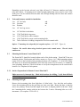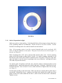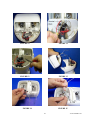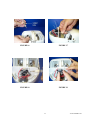
1
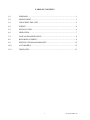
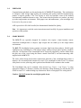
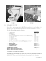
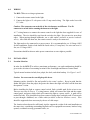
PRODUCT
SUPPORT
MANUAL
Y1-03-0158
Rev. D
RCL-75
Product No. 1946
Remote Control
Searchlight System
ACR Electronics, Inc.
5757 Ravenswood Road
Fort Lauderdale, Fl 33312
+1(954) 981-3333 · Fax +1 (954) 983-5087
www.acrelectronics.com
Email: [email protected]
A Chelton Group company
TABLE OF CONTENTS
1.0
FORWARD .............................................................................................................1
2.0
SEARCHLIGHT......................................................................................................1
3.0
UNPACKING THE UNIT ......................................................................................2
4.0
WIRING ..................................................................................................................4
5.0
INSTALLATION ....................................................................................................4
6.0
OPERATION...........................................................................................................7
7.0
CARE AND MAINTENANCE...............................................................................8
8.0
BULB REPLACEMENT.........................................................................................8
9.0
SPECIFICATIONS and WARRANTY.................................................................12
10.0
ACCESSORIES.....................................................................................................13
11.0
TEMPLATES ........................................................................................................13
i
Y1-03-0158 Rev. D
1.0
FORWARD
Congratulations and thank you for purchasing the ACR RCL-75 Searchlight. The combination
of computer aided design; high quality raw materials and quality-controlled manufacturing
produce a superior product. The Test Facility at ACR can reproduce some of the harshest
environmental conditions known to man. This assures that the products we produce can stand
up to the tough marine environment. With proper care and maintenance, your searchlight will
be in service for years to come.
ACR is proud to be ISO 9001certified, the International Standard for Quality.
Note. It is important to read this entire instruction manual carefully for proper installation and
operation of this product.
2.0
SEARCHLIGHT
The RCL-75 was specially designed for mariners who require a high intensity remote
controlled searchlight that is compact, light weight and can stand up to the tough marine
environment.
The RCL-75 Searchlight System contains an intense light beam that produces 180,000 peak
candlepower by combining two 55W halogen lamps with our unique optical quality, parabolic
reflectors. All functions of the Searchlight can be electrically operated by remote control from
the pilot area of the vessel using the remote control Point Pad™, and interconnecting cable
supplied with the RCL-75.
The sleek, robust design and modern construction materials of the searchlight body makes it
attractive for recreational and commercial vessels. The searchlight is made of an UV resistant
ASA plastic to resist yellowing, and is gasketed and finished to be resistant to the weather.
The Searchlight Unit can be mounted where desired (see Figure 1 and Figure 2), using
appropriate length 1/4" diameter, stainless steel fasteners. When mounting, be sure that the unit
is able to rotate 361° without hitting any obstructions. Refer to Paragraph 4 for wiring details.
Caution - DO NOT mount the searchlight upside down.
1
Y1-03-0158 Rev. D
FIGURE 1
3.0
FIGURE 2
UNPACKING THE UNIT
Every effort is made to assure that the RCL-75 has been delivered in good condition. It is
important to make sure that all parts are present before you begin installation. (see Figure 3)
The RCL-75 Searchlight contains the following:
-
Light Assembly
Deck Mount
17’ wire harness
Remote Control Point Pad™ and extra cover for flush mounting
4 ea. S/S Allen Bolts
4 ea. S/S Nuts
4 ea. S/S Flat washers
4 ea. S/S Lock washers
Special L wrench (Allen wrench and Phillips head screwdriver)
2 ea. U clamps for Remote Control Point Pad™ flush mount
Mounting Gasket
Surface Mount Gasket
Flush Mount Gasket
Light Base Mount Template*
Remote Control Panel Template (Flush)*
Remote Control Panel Template (Surface)*
Part Number
A3-06-2177
A1-18-1724
9426
9428
A1-05-0734-1
A1-05-0736
A1-05-0741
A1-05-0737
T1-04-0047
A1-17-1366
A1-25-0132
A1-25-0135-1
A1-25-0135-2
Y1-03-0158-1
"
"
*Templates are on a separate sheet in this box.
If by chance your kit is missing a part, please call our Toll free Customer Service Phone at
(800) 432-0227. Please provide the Serial number of your unit and location of purchase.
2
Y1-03-0158 Rev. D
FIGURE 3
3
Y1-03-0158 Rev. D
4.0
WIRING
The RCL-75 has two wiring requirements:
1. Connect the remote control to the light
2. Connect the light to 12-volt power with 15 amp rated wiring. The light works best with
13.5 volts.
Caution - The connectors on each side of the wire harness are different. Test fit
connector to switch before running the harness to the light.
A 17' wiring harness to connect the remote control to the light has been supplied for ease of
installation. The wire should be run from the switch to the light. Do not run wire near sharp
edges. When passing through bulkheads, use a cable outlet (available at marine hardware
stores). After cable has been run, the remote control is ready to be connected.
The light needs to be connected to a power source. It is recommended to use 14 Gauge AWG
for this installation. Positive lead should be fused with a (15 Amp fuse). For wire runs over 16
feet, use 12 Gauge AWG.
Precautions should be taken to make power connections as water tight as possible.
5.0
INSTALLATION
5.1
Location Selection
In order for the RCL-75 to achieve maximum performance, care and consideration should be
given to the selection of a mounting location for the Searchlight and Remote Control Panel.
Typical mount locations include, bow pulpit, fore deck, and cabin hardtop. See Figure 1 and 2.
Caution: Do not mount the searchlight upside down.
Mounting surface should be flat and parallel to the water’s surface. Keep in mind that the
further the light is from the pulpit, the greater the chance that light will reflect off the boat into
the operator’s vision.
Before installing the light or remote control switch, find a suitable path for the wires to run.
There are two sets of wires, a 17' wiring harness, which will connect the light and the remote
control panel, and power leads which will connect the light to a power source. A path will be
needed for both. Wire should be kept from contact of sharp edges, and tight radii. If wire needs
to pass through a bulkhead, use a cable outlet (available at marine hardware stores). Wire
should be supported where necessary by the use of cable straps.
The location selected must be sufficiently rigid to support the weight of the total installation at
the same time, considering surroundings hazards such as equipment movement, hatches being
opened, accidental covering, personnel traffic, etc.
4
Y1-03-0158 Rev. D
Depending on the location selected, your light will need 1/4” diameter stainless steel bolts,
nuts, and washers. If mounting area is robust enough panhead lag screws may be used. If the
surface area can be reached from the under side, through bolting with lock nuts and washers
should be used.
5.2
Tools and fasteners needed for installation
4 ea. 1/4” dia. bolts
4 ea. Lock nuts
4 ea. Washers
4 ea. 1/4” dia. Lag screws
1 ea.
1 ea.
1 ea.
1 ea.
1 ea.
and
and
or
1/4" Drill bit for bolt holes
or
17/64" Drill bit for lag screws
15/16" Drill bit for cable clearance
13/64" Drill bit for remote switch mounting bolts
Tube of silicone or bedding compound to close hole around cable.
Option: 1”mounting riser shapeable for irregular surfaces. (P/N 9427 - Figure 4)
Caution - Be careful when using electrical power tools around water. Electric shock
could occur.
5.3
Mounting the Remote Control Point Pad™
The Point Pad™ should be located within reach of the helm station. Point Pad™ has two
mounting options. Flush mount and Surface mount.(see Figures 6 & 7) Both mounting options
require access to the backside of the mounting location. (see Templates – Y1-03-0158-1) Make
sure there are no obstructions behind the area where the switch is to be located. (i.e. bulkheads,
wires, plumbing, hardware.) Check in advance to verify the wiring harness can be routed to this
location. Use Templates for hole pattern.
5.3.1 Surface Preparation for Remote Control Point Pad™
Make sure area is clean and dry. Mark hole locations for drilling. Verify that drill hole
will not impact or harm other items (wires, plumbing, hardware bulkhead).
5.4
Mounting the Light
Remove deck mounting plate from light base (4 Allen bolts). Save the bolts and washers.
Locate the mounting plate on the spot that you want your light. Rotate the plate so that the
arrows are pointing forward and the length of the arrow is aligned parallel to the keel. Mark
the 4 mounting holes, starting with the one between the 2 arrows. Mounting holes are in 90°
increments. (See template Y1-03-0158-1)
5
Y1-03-0158 Rev. D
FIGURE 4
5.4.1 Surface Preparation for light
Make sure surface is clean and dry. Verify that drill holes will not impact or harm other items
(wires, plumbing, hardware or bulkheads). Decide on the use of screws or bolts. Can the
backside of mounting surface be reached to install nuts and washers?
Note: If the mounting surface is not flat, a special shapeable plate can be purchased, (P/N
9427), to adapt the light base to the surface. This plate can also be used to raise the light 1” if
desired. (see Figure 4)
Drill 4 mounting holes (1/4") and a centered cable clearance hole (3/4"). Put the mounting
gasket on the deck mount (or shaped plate, if used). Use caulk or bedding compound to seal
bolt and wire holes before deck mount is attached to deck. The plates are keyed to each other
and to the light, be sure the arrows are pointing in the correct direction. (the light will rotate
180° either way from the arrows).
Use marine grade 316 stainless steel bolts, nuts, and lock washers to fasten the plate(s) to the
mounting surface. Install and connect the control cable and (+) Red and (-) Black power leads.
Seal hole if desired. Leave at least 8" of wire coiled in the base of light to allow for servicing.
(see Figure 5)
Seat the light assembly on the deck mount. Make sure the key is mated and the gasket edge is
not pinched. Reinstall the four (4 ) stainless steel Allen bolts with the flat washer next to the
plastic and the lock washer under the bolt head. (Allen wrench for these bolts is furnished).
Tighten securely.
6
Y1-03-0158 Rev. D
FIGURE 5
6.0
OPERATION
The remote control Point Pad™ is simple to operate. A red LED tells you that power is
available. A green LED lights when the light is in use.
The ON/OFF button turns the dual beams ON and OFF. The control disk is pushed down in
the direction you want to aim the light. Elevation and rotation can be operated at the same
time and with the light in the ON or OFF mode.
FIGURE 6
FIGURE 7
7
Y1-03-0158 Rev. D
7.0
CARE AND MAINTENANCE
The RCL-75 is relatively maintenance free. Clean the exterior of the light with a mild
detergent and water if desired. Rotate the light left, then right and up then down periodically to
keep motors and turning surfaces clean and operational.
Caution – DO NOT rotate light manually. This will strip the gear rack.
8.0
BULB REPLACEMENT
The bulbs are rated at over 200 hours of operation. If one burns out, you can replace it with a
prefocused, desiccated bulb assembly from ACR. (Product No. 9403) We recommend that you
replace both bulbs at the same time.
Note: One bulb will continue to run if one burns out, to give you 100,000 CD to get home with.
To replace a bulb:
1) Do not rotate light head by hand. This will strip the gear rack. Do not remove the front
bezel to replace the bulbs. Before replacing bulb, move lens via remote control to the
farthest down position, then it is recommended to remove the light from its mounting
location. Lamps should be changed while light is at a suitable work place.
2) Remove top cover, (4 top screws at sides of front, and 4 counter sunk phillips screws
attaching top cover to lower case). Use L wrench furnished with light. (see Figure 8)
3) Carefully remove top cover by lifting straight up. (see Figure 9)
4) Observe shape and position of the bulb wire loop. (see Figure 10)
5) Disconnect bulb wires from terminal block and with small wire snips, remove the cable ties
from bulb wires. (see Figure 11)
6) At the point where the grey bulb wire passes through the partition wall, remove the sealant
with a razor, screwdriver or snips. Beneath the sealant is a wire sleeve. Hold this sleeve
with needle nose pliers and push through the partition wall. (see Figure 12)
7) Gently remove the entire reflector assembly from the body. (see Figure 13)
8) Place the reflector assembly face down.
9) Remove rubber sleeve. (see Figure 14)
10) Squeeze the 2 wire ends of the G-clip together to get release of the insert pin from the
reflector and remove the clip. (see Figure 15)
11) Pull bulb out and discard
12) Install new bulb, aligning the larger hole toward the back of the tube with the G-clip hole.
Do not touch bulb with bare hands. (see Figure 16)
13) Re-install G-clip
14) Install the rubber sleeve over the base of the reflector, flush to the G-clip.
15) Hold the reflector assembly in one hand and feed the bulb wires through the partition. (see
Figure 17)
16) Seal metal sleeves on the bulb wires half way through the partition wall. (see Figure 18)
8
Y1-03-0158 Rev. D
17) Set reflector housing into the swivel sockets with the light pointed down and carefully
engage the gear rack. (make sure the drain hole and serial number is facing down).
18) Form the loops in the bulb wires in the same shape as the ones removed. (looking into the
back, the gear-toothed rack is on the right and the smooth arch is on the left). The wires on
the left are formed sharply down and back of the bulb assembly, then a 1” diameter loop is
formed back up and toward the smooth arch, continuing around to pass through the
partition below the lever switch.
The bulb wires on the right side are formed sharply up and back at the back of the bulb
assembly, then a 1” diameter loop is formed on the gear side and continued to pass through
the partition wall above the lever switch. These loops allow the elevation movements and
must not interfere with the lever switches or touch the reflector.
19) When the bulbs are properly installed to this point, you will have one long wire and one
short wire for each bulb.
20) The short wire of the left bulb and the long wire of the right bulb are joined together and
inserted into the lower left hole of the terminal block and screw tightened securely.
21) The short wire of the right bulb and the long wire of the left bulb are joined together and
inserted into the upper right side hole of the terminal block and screw tightened securely.
Gather wires together and install new cable ties. (see Figure 19)
22) Replace the top cover carefully, making sure the partition is seated in its proper groove and
the screw holes at the front match the metal braces.
23) Reinstall the four (4) long cover screws starting from the back and work forward, then
install the four (2) top screws at each side (total of 4). Tighten all screws securely, taking
care not to overtighten.
24) Light assembly is ready to be reinstalled on mount. Reattach control cable and wire power
leads. Precautions should be taken to make power connections as water tight as possible.
FIGURE 8
FIGURE 9
9
Y1-03-0158 Rev. D
FIGURE 10
FIGURE 11
FIGURE 12
FIGURE 13
FIGURE 14
FIGURE 15
10
Y1-03-0158 Rev. D
FIGURE 16
FIGURE 17
FIGURE 18
FIGURE 19
11
Y1-03-0158 Rev. D
9.0
RCL-75 SPECIFICATIONS (with Remote Control Point Pad™)
9.1
Specifications
RCL-75
Power Requirements
12 – 14 Volts DC
Current Draw
10 Amps
Power Wire Leads
14 Gauge
Wire harness
Peak Beam Candle Power
17’ minimum with Molex quick connect
locking connectors on each end
180,000 Candela*
Lamp
Dual beam 55 watt halogen
Reflector Size
6” x 4.5”
Beam Spread (degrees)
Horizontal
8° Approx.
Vertical
3° Approx.
Elevation Angle (degrees)
9.2
Up
18°
Down
45°
Turning Angle (degrees)
361°
Elevation Speed (top to bottom)
10 seconds
Turning Speed (1 revolution)
20 seconds (18° per sec approx.)
Weight
*Measured with direct light meter at 100’
4.2 Lbs. (1.9 kg)
Warranty
This product is warranted against factory defect in material and workmanship for a period of
one year from date of purchase or receipt as a gift. During the warranty period ACR
Electronics, Inc. will repair or, at its option, replace at no cost to you for labor, materials or
return transportation, provided you obtain a Return Authorization from ACR Electronics, Inc.,
5757 Ravenswood Road, Ft. Lauderdale, Fl. 33312-6645. To obtain a Return Authorization,
call our Customer Service Department at (800) 432-0227. This warranty does not apply if the
product has been damaged by accident or misuse, or as a result of service or modification by
other than the factory.
Except as otherwise expressly stated in the previous paragraph, the COMPANY MAKES NO
REPRESENTATION OR WARRANTY OF ANY KIND, EXPRESS OR IMPLIED, AS TO
MERCHANTABILITY, FITNESS FOR A PARTICULAR PURPOSE, OR ANY OTHER
MATTER WITH RESPECT TO THIS PRODUCT. The Company shall not be liable for,
consequential or special damages.
In order to place the warranty in effect, the accompanying registration card must be returned to
us within ten days of purchase or receipt as a gift.
12
Y1-03-0158 Rev. D
10.0
ACCESSORIES
Here is a list of options and replacement parts that can be ordered for your searchlight.
1)
2)
3)
4)
5)
11.0
Product Number
Mounting riser.
9427
This will raise the searchlight 1" from mounting surface to allow for clearance of deck
hardware. It can be shaped to adapt light to uneven surfaces.
Replacement bulbs
9403
17' Extension Wire harness
9426
nd
2 station harness adapter (splitter)
9442
nd
2 station Point Pad™ (flush & surface mount)
9428
TEMPLATES (see Y1-03-0158-1)
13
Y1-03-0158 Rev. D