1
Operating and installation instructions
Cooker hood
To avoid the risk of accidents or damage to this appliance,
it is essential to read these instructions before it is installed and used for
the first time.
en - GB
M.-Nr. 09 733 840
Contents
Warning and Safety instructions . . . . . . . . . . . . . . . . . . . . . . . . . . . . . . . . . . . . . 4
Caring for the environment . . . . . . . . . . . . . . . . . . . . . . . . . . . . . . . . . . . . . . . . . 13
Guide to the appliance . . . . . . . . . . . . . . . . . . . . . . . . . . . . . . . . . . . . . . . . . . . . 14
Modes of operation . . . . . . . . . . . . . . . . . . . . . . . . . . . . . . . . . . . . . . . . . . . . . . . 16
Con|ctivity 2.0 . . . . . . . . . . . . . . . . . . . . . . . . . . . . . . . . . . . . . . . . . . . . . . . . . . . 17
Operation (Automatic mode) . . . . . . . . . . . . . . . . . . . . . . . . . . . . . . . . . . . . . . . 18
Cooking with the Con|ctivity 2.0 function
(Automatic mode) . . . . . . . . . . . . . . . . . . . . . . . . . . . . . . . . . . . . . . . . . . . . . . . . . 18
After cooking . . . . . . . . . . . . . . . . . . . . . . . . . . . . . . . . . . . . . . . . . . . . . . . . . . . . . 19
Leaving automatic mode temporarily . . . . . . . . . . . . . . . . . . . . . . . . . . . . . . . . . . 20
Operation (Manual mode) . . . . . . . . . . . . . . . . . . . . . . . . . . . . . . . . . . . . . . . . . . 21
Cooking without the Con|ctivity 2.0 function
(Manual mode). . . . . . . . . . . . . . . . . . . . . . . . . . . . . . . . . . . . . . . . . . . . . . . . . . . . 21
To switch the fan on s . . . . . . . . . . . . . . . . . . . . . . . . . . . . . . . . . . . . . . . . . . . . . 21
To select a power level . . . . . . . . . . . . . . . . . . . . . . . . . . . . . . . . . . . . . . . . . . . . . 21
Run-on option "5¢15" . . . . . . . . . . . . . . . . . . . . . . . . . . . . . . . . . . . . . . . . . . . . . . 21
To switch the fan off s . . . . . . . . . . . . . . . . . . . . . . . . . . . . . . . . . . . . . . . . . . . . . 21
Hob lighting I. . . . . . . . . . . . . . . . . . . . . . . . . . . . . . . . . . . . . . . . . . . . . . . . . . . . 21
Power management system . . . . . . . . . . . . . . . . . . . . . . . . . . . . . . . . . . . . . . . . . 22
Operation (Automatic and manual modes) . . . . . . . . . . . . . . . . . . . . . . . . . . . . 23
Filter operating hours counter [ . . . . . . . . . . . . . . . . . . . . . . . . . . . . . . . . . . . . 23
Sensor tones . . . . . . . . . . . . . . . . . . . . . . . . . . . . . . . . . . . . . . . . . . . . . . . . . . . . . 25
Cleaning and care . . . . . . . . . . . . . . . . . . . . . . . . . . . . . . . . . . . . . . . . . . . . . . . . 26
Housing . . . . . . . . . . . . . . . . . . . . . . . . . . . . . . . . . . . . . . . . . . . . . . . . . . . . . . . . . 26
Grease filters . . . . . . . . . . . . . . . . . . . . . . . . . . . . . . . . . . . . . . . . . . . . . . . . . . . . . 27
Resetting the grease filter operating hours counter . . . . . . . . . . . . . . . . . . . . 28
Fitting and replacing the charcoal filters . . . . . . . . . . . . . . . . . . . . . . . . . . . . . . . . 29
Resetting the charcoal filter operating hours counter . . . . . . . . . . . . . . . . . . . 29
Appliance dimensions . . . . . . . . . . . . . . . . . . . . . . . . . . . . . . . . . . . . . . . . . . . . . 30
Safety distance between hob and cooker hood (S) . . . . . . . . . . . . . . . . . . . . . 31
Installation . . . . . . . . . . . . . . . . . . . . . . . . . . . . . . . . . . . . . . . . . . . . . . . . . . . . . . 32
Installation accessories . . . . . . . . . . . . . . . . . . . . . . . . . . . . . . . . . . . . . . . . . . . . . 32
Connection for air extraction . . . . . . . . . . . . . . . . . . . . . . . . . . . . . . . . . . . . . . . 43
Condensate trap . . . . . . . . . . . . . . . . . . . . . . . . . . . . . . . . . . . . . . . . . . . . . . . . . . 44
Silencer . . . . . . . . . . . . . . . . . . . . . . . . . . . . . . . . . . . . . . . . . . . . . . . . . . . . . . . . . 45
Electrical connection . . . . . . . . . . . . . . . . . . . . . . . . . . . . . . . . . . . . . . . . . . . . . 46
2
Contents
Activating the Con|ctivity 2.0 function. . . . . . . . . . . . . . . . . . . . . . . . . . . . . . . 47
Installing the Con|ctivity 2.0 stick. . . . . . . . . . . . . . . . . . . . . . . . . . . . . . . . . . . . . 47
Activating the Con|ctivity 2.0 function on the cooker hood . . . . . . . . . . . . . . . . . 47
Activating the Con|ctivity 2.0 function on the hob . . . . . . . . . . . . . . . . . . . . . . . . 48
Checking activation . . . . . . . . . . . . . . . . . . . . . . . . . . . . . . . . . . . . . . . . . . . . . . . . 48
Deactivating . . . . . . . . . . . . . . . . . . . . . . . . . . . . . . . . . . . . . . . . . . . . . . . . . . . . . . 49
After Sales Service . . . . . . . . . . . . . . . . . . . . . . . . . . . . . . . . . . . . . . . . . . . . . . . 50
Technical data . . . . . . . . . . . . . . . . . . . . . . . . . . . . . . . . . . . . . . . . . . . . . . . . . . . 51
Declaration of conformity . . . . . . . . . . . . . . . . . . . . . . . . . . . . . . . . . . . . . . . . . 51
3
Warning and Safety instructions
This appliance complies with all relevant safety requirements.
Improper use of the appliance can, however, present a risk of
both personal injury and damage to property.
To avoid the risk of accidents and damage to the appliance,
please read these instructions carefully before installation and
before using it for the first time. They contain important
information on the safety, installation, use and maintenance of the
appliance.
Miele cannot be held liable for damage caused by
non-compliance with these Warning and Safety instructions.
Keep these instructions in a safe place and ensure that new users
are familiar with the content. Pass them on to any future owner.
Correct application
~ The cooker hood is intended for use in domestic households and
similar working and residential environments.
~ The appliance is not intended for outdoor use.
~ It must only be used as a domestic appliance to extract vapours
and remove odours from cooking.
~ The appliance must not be used in a non-stationary location
(e.g. on a ship).
4
Warning and Safety instructions
~ The appliance can only be used by people with reduced
physical, sensory or mental capabilities, or lack of experience and
knowledge, if they are supervised whilst using it, or have been
shown how to use it in a safe way and recognise and understand the
consequences of incorrect operation.
Safety with children
~ Children under 8 years of age must be kept away from the cooker
hood unless they are constantly supervised.
~ Children 8 years and older may use the cooker hood only if they
have been shown how to use it in a safe way and understand the
hazards involved.
~ Children must not be allowed to clean or maintain the appliance
unsupervised.
~ Please supervise children in the vicinity of the appliance and do
not let them play with it.
~ Danger of suffocation. Packaging, e.g. plastic wrappings, must
be kept out of the reach of babies and children. Whilst playing,
children could become entangled in packaging or pull it over their
head and suffocate.
5
Warning and Safety instructions
Technical safety
~ A damaged appliance can be dangerous. Check the appliance
for visible signs of damage. Do not use a damaged appliance.
~ The electrical safety of this appliance can only be guaranteed if it
is correctly earthed. It is essential that this standard safety
requirement is met. If in any doubt please have the electrical
installation tested by a qualified electrician.
~ To avoid the risk of damage to the appliance, the connection data
(frequency and voltage) on the data plate must correspond to the
mains electricity supply. Check that this is the case before
connecting the appliance. Consult a qualified electrician if in any
doubt.
~ Do not connect the appliance to the mains electrical supply by a
multi-socket adapter or extension lead. These are a fire hazard and
do not guarantee the required safety of the appliance.
~ For safety reasons, this appliance may only be used when it has
been fully installed.
~ Tampering with electrical connections or components and
mechanical parts is highly dangerous to the user and can cause
operational faults. Only open the housing as described in the
instructions given in the installation sheet and in the Cleaning and
care section of this booklet. Under no circumstances should any
other parts of the housing be opened.
~ Unauthorised installation, maintenance and repairs can cause
considerble danger to users. Installation, maintenance and repair
work must only be carried out by a Miele authorised technician.
6
Warning and Safety instructions
~ A damaged connection cable must only be replaced by an
approved and suitably qualified technician.
~ Miele can only guarantee the safety of the appliance when
original Miele replacement parts are used. Faulty components must
only be replaced by genuine Miele original spare parts.
~ During installation, maintenance and repair work, the appliance
must be disconnected from the mains electricity supply.
7
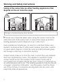
Warning and Safety instructions
Using at the same time as other heating appliances that
depend on the air from the room
Danger of poisoning by toxic fumes.
~ Great care should be taken when using the cooker hood at the
same time and in the same room or area of the house as another
heating appliance which depends on air in the room.
Such appliances include gas, oil, wood or coal-fired boilers and
heaters, continuous flow or other water heaters, gas hobs, cookers
or ovens which draw air in from the room and duct exhaust gases
out through a chimney or extraction ducting.
Cooker hoods draw air in from the room in which they are installed
and from neighbouring rooms. This applies to extraction mode
cooker hoods and to recirculation mode cooker hoods with a
recirculation box located outside the room. If there is insufficient air,
an underpressure will occur. The heating appliance may be starved
of oxygen, impairing combustion. Harmful gases could be drawn
out of the chimney or extraction ducting back into the room, with
potentially fatal consequences.
8
Warning and Safety instructions
In order to ensure safe operation, and to prevent gases given off by
the heating appliances from being drawn back into the room when
the cooker hood and the heater are in operation simultaneously, an
underpressure of 0.04 mbar (4 pa) is the maximum permissible in
the room.
This can be achieved by providing adequate ventilation such as air
inlets which cannot be blocked, in windows, doors and outside wall
vents, or by other technical measures, such as ensuring that the
cooker hood can only be switched on when the heating appliance is
switched off or vice versa.
The ventilation must have the appropriate cross-sectional area to
ensure an adequate supply of air.
A ventilation brick alone is not generally sufficient to ensure safe
ventilation.
, The overall ventilation condition of the dwelling must be taken
into account. If in any doubt, the advice of a competent builder
or, for gas, a qualified gas fitter (GasSafe registered in the UK)
must be sought.
If the hood is being operated in recirculation mode and the air is
being directed back into the kitchen, the above restrictions do not
apply.
9
Warning and Safety instructions
Correct use
~ Danger of burning with open flames. Never use an open flame
beneath the cooker hood. To avoid the danger of fire, do not flambé
or grill over an open flame. When switched on, the cooker hood
could draw flames into the filter. Fat particles sucked into the cooker
hood present a fire hazard.
~ When cooking with a gas hob, a build-up of heat can damage the
cooker hood.
– When using the cooker hood over a gas hob, ensure that any
burners in use are always covered by a pan. Switch the cooking
zone off when a pan is removed, even for a short time.
– Select pans which are suitable for the size of the cooking zone.
– Control the flame so that it does not spread out beyond the sides
of the pan.
– Do not allow the pans to overheat excessively (e.g. when using a
wok).
~ Always switch the cooker hood on when using the hob, otherwise
condensation may collect in the hood, which could cause corrosion.
~ Overheated oil and fat can ignite and could set the cooker hood
on fire. When cooking with oil or fat, chip pans and deep fat fryers
etc, do not leave the pans unattended. Never leave an open grill
unattended when grilling.
10
Warning and Safety instructions
~ Do not use the cooker hood without the filters in place. This way
you will avoid the risk of grease and dirt getting into the appliance
and hindering its smooth operation.
~ The filters should be regularly cleaned or changed as
appropriate. Saturated filters are a fire hazard.
~ The cooker hood can get very hot during cooking due to heat
rising from the hob.
Do not touch the housing or the grease filters until the cooker hood
has cooled down.
~ Do not use a steam cleaner to clean this appliance. Steam could
reach electrical components and cause a short circuit.
Correct installation
~ Check with the manufacturer of your cooking appliance whether it
is safe to install a hood above it.
~ The minimum safety distance between the top of the cooker or
hob and the bottom of the cooker hood given in the "Appliance
dimensions" section of this booklet must be maintained, unless the
manufacturer states that a greater safety distance is required.
If more than one cooking appliance is fitted beneath the cooker
hood, and they have different minimum safety distances to the
cooker hood, select the greater distance.
~ Safety regulations prohibit the fitting of a cooker hood over solid
fuel stoves.
11
Warning and Safety instructions
~ All ducting, pipework and fittings must be of non-flammable
material. These can be obtained from the Miele Spare Parts
department or from builders' merchants.
~ The appliance must not be connected to a chimney or vent flue
which is in use. Neither should it be connected to ducting which
ventilates rooms with fireplaces.
~ If exhaust air is to be extracted into a chimney or ventilation duct
no longer used for other purposes, seek professional advice.
Accessories
~ Only use genuine original Miele accessories with this appliance.
Using spare parts or accessories from other manufacturers will
invalidate the guarantee, and Miele cannot accept liability.
12
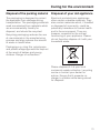
Caring for the environment
Disposal of the packing material
Disposal of your old appliance
The packaging is designed to protect
the appliance from damage during
transportation. The packaging materials
used are selected from materials which
are environmentally friendly for
disposal, and should be recycled.
Electrical and electronic appliances
often contain valuable materials. They
also contain materials which, if handled
or disposed of incorrectly, could be
potentially hazardous to human health
and to the environment. They are,
however, essential for the correct
functioning of your appliance. Please
do not therefore dispose of it with your
household waste.
Recycling packaging reduces the use
of raw materials in the manufacturing
process and also reduces the amount
of waste in landfill sites.
Packaging e.g. cling film, polystyrene
and plastic wrappings must be kept out
of the reach of babies and young
children. Danger of suffocation!
Please dispose of it at your local
community waste collection / recycling
centre or contact your dealer for
advice. Ensure that it presents no
danger to children while being stored
for disposal.
13
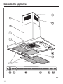
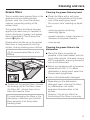
Guide to the appliance
14
Guide to the appliance
a Telescopic piece
n Sensor for the grease filters
b Tower
The sensor lights up when the grease
filters need to be cleaned.
c Canopy
d Controls
e Grease filters
f Spacer frame
The spacer frame creates a shadow
gap between the tower and the ceiling.
The cooker hood can be installed with
or without the spacer frame.
g Recirculation grille
(only for recirculation mode)
h Hob lighting
i Charcoal filter
(special accessory for recirculation
mode)
j Sensor for switching the fan on
and off
k Sensor for the hob lighting
It is used to reset the operating hours
counter every time the grease filters are
cleaned (see "Cleaning and care").
It can also be used to check and alter
the operating hours counter.
o Sensor for the charcoal filters
The sensor for the charcoal filter lights
up when the charcoal filter used in
recirculation mode needs to be
replaced. For this to happen, the
operating hours counter needs to be
activated before the appliance is used
for the first time.
The sensor is used to reset the
operating hours counter every time the
charcoal filters are replaced (see
"Cleaning and care").
It can also be used to check and alter
the operating hours counter.
l Sensors for selecting the fan
power level
m Sensor for the run-on option
This sensor activates the run-on option.
The fan can be set to switch off
automatically after either 5 or 15
minutes.
For information about using the
appliance, see "Operation".
15
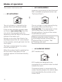
Modes of operation
The cooker hood works with
. . . air recirculation:
. . . air extraction:
(requires a conversion kit and charcoal
filter, available as optional extras: see
"Technical Data")
The air is drawn in, cleaned by the
grease filters and directed outside.
If the on-site ventilation system does
not have a non-return flap, then the
non-return flap supplied with the
appliance must be fitted in the exhaust
socket of the motor unit.
Having a non-return flap fitted in the
ducting ensures that air, once ducted
to the outside, cannot get back into the
room again.
The flap is closed when the cooker
hood is switched off.
When the cooker hood is switched on,
the non-return flap opens for the
cooking vapours to be blown directly
outside.
The air is drawn in and cleaned first by
the grease filters and then by a
charcoal filter. The cleaned air is then
recirculated back into the kitchen
through grilles in the top of the cooker
hood extension piece.
Before using the cooker hood in
recirculation mode, ensure that the
charcoal filter is in place. See
"Cleaning and care".
. . . an external motor:
(EXT models only)
EXT models are designed to be
connected to an external motor located
outside the room.
The external motor is connected to the
cooker hood by means of a control cable,
and is operated by the controls on the
cooker hood.
16
Modes of operation
Con|ctivity 2.0
Automatic control
This cooker hood is fitted with a
communication module which enables
the operation of the cooker hood to be
automatically controlled by the
operating status of a Miele electric hob
with onset controls.
The hob transmits information about its
operating status to the cooker hood via
radio.
– When the hob is switched on, the
cooker hood hob lighting switches on
and after a short time the cooker
hood fan switches on.
– During cooking the cooker hood
automatically sets its power level
according to the number of cooking
zones in operation and their power
levels.
– After the hob has been switched off,
the cooker hood fan and hob lighting
will switch off automatically after a
period of time.
For communication to take place, the
hob must be fitted with the Con|ctivity
2.0 stick a.
The Con|ctivity 2.0 stick for the hob is
supplied with this cooker hood. Please
refer to the installation instructions for
the Con|ctivity 2.0 stick to check
whether connection is possible.
To use the Con|ctivity 2.0 function a
radio connection between the hob and
the cooker hood must be established
(see "Activating the Con|ctivity 2.0
function").
For more detailed information about this
function, please see "Operation".
17
Operation (Automatic mode)
When Con|ctivity 2.0 is activated, the
cooker hood always operates in
automatic mode (see "Activating the
Con|ctivity 2.0 function").
To operate the cooker hood manually,
see "Cooking without the Con|ctivity
2.0 function".
Cooking with the Con|ctivity
2.0 function
(Automatic mode)
^ Switch on the hob and select a
setting.
The cooker hood lighting will come on.
After a few seconds the fan will come
on, first at level 2, then switching
immediately to level 1.
During cooking the cooker hood
automatically sets its power level
according to the number of cooking
zones in operation and their power
levels.
^ If a higher setting for a hob cooking
zone is selected or more cooking
zones are switched on, the hood will
then operate at a higher fan power
level as well.
^ Similarly, if a lower setting is selected
for a cooking zone or cooking zones
are switched off, the fan power level
of the cooker hood will be adjusted
accordingly.
The power level is adjusted according
to the total number of cooking zones
and power settings in use on the hob.
18
Examples for levels 1 to 4
Reaction time
The reaction of the cooker hood is
slightly delayed because altering the
power settings on the hob will not
necessarily result in an increase or
decrease in cooking vapours.
A delay in the reaction of the cooker
hood can also be because the hob
transmits information to the cooker
hood at intervals.
The cooker hood can react within
seconds or a few minutes.
Operation (Automatic mode)
Frying food
After cooking
^ If the hob is switched on at the
highest setting and is turned down
to a lower setting after approx. 60 to
90 seconds*, a frying process is
recognised.
(* 60 seconds to 5 minutes with a
HiLight hob).
^ When all cooking zones are switched
off, the fan power level is reduced in
stages within the next few minutes
and then eventually switched off.
This delay will allow any lingering
odours in the air to be neutralised.
The cooker hood switches itself on and,
when the hob is turned down to a lower
setting, switches itself to level 3 and
remains at this level for approx.
5 minutes.
After this period, the fan power level is
determined by the Con|ctivity 2.0
function.
^ You can also manually select another
fan power level early if you wish.
– The fan will reduce immediately from
Intensive setting IS to level 3.
– If it is operating on power level 3 it
will switch to power level 2 after
approx. 1 minute.
– From power level 2 it will switch to
power level 1 after 2 minutes.
– Then after 2 minutes operating at
power level 1, the fan will switch off.
– The lighting will go out 30 seconds
later.
The cooking process is complete.
19
Operation (Automatic mode)
Leaving automatic mode
temporarily
^ You can also leave automatic mode
during cooking, by
– manually selecting a different fan
power level, or
– manually switching off the cooker
hood, or
– activating the run-on option "" on
the cooker hood.
The fan will then switch off after the
run-on time selected.
The lighting will remain on.
The cooker hood can now be operated
manually (see "Cooking without the
Con|ctivity 2.0 function").
^ The cooker hood will revert to automatic mode, if
– after manually selecting a fan power
level, you do not operate the cooker
hood for approx. 5 minutes.
– the fan power level you have
selected manually is the same as the
power level which is selected
automatically.
– the cooker hood fan and the hob are
switched off for at least 30 seconds.
Automatic mode will start again the
next time the hob is switched on.
20
^ If you wish to operate the cooker
hood manually for a complete
cooking process, switch the cooker
hood fan on before the hob.
If the cooker hood and hob were
switched off at least 30 seconds after
cooking, automatic mode will resume
next time the hob is switched on.
Operation (Manual mode)
Cooking without the
Con|ctivity 2.0 function
(Manual mode)
The Con|ctivity 2.0 function must not
be activated for this mode.
Run-on option "5¢15"
It is advisable to leave the fan running
for a few minutes after cooking has
finished to neutralise any lingering
odours in the air.
However, manual operation is
temporarily possible even if the
Con|ctivity 2.0 function is activated
(see "Leaving automatic mode
temporarily").
The fan can be set to switch off
automatically after 5 or 15 minutes.
To switch the fan on s
– Touch once = The fan will switch off
after 5 minutes (5 ¢ will light up).
^ Touch the On/Off sensor s.
The fan will switch on at power level 2.
To select a power level
Depending on the intensity of the
cooking vapours, levels 1 to 3 are
usually sufficient for normal cooking.
^ After cooking has finished, touch the
Run-on option sensor ¢ whilst the
fan is still running
– Touch twice = The fan will switch off
after 15 minutes (¢15 will light up).
^ If you touch the Run-on sensor ¢
again, the fan remains on (5 ¢15
goes out).
To switch the fan off s
^ Select the level you require by
touching the 1, 2 or 3 sensor.
^ Touch the On/Off sensor s to switch
the fan off.
Intensive setting
Hob lighting I
^ For short periods of cooking food
with intensive vapours and a strong
aroma, e.g. when searing meat, you
may wish to select level IS, the
Intensive setting.
The hob lighting can be switched on
and off independently of the fan.
^ Touch the hob lighting sensor I.
21
Operation (Manual mode)
Power management system
The cooker hood features a Power
management system to help save
energy.
The fan power level is reduced and the
lighting is switched off automatically.
– If the Intensive setting is selected,
the fan will automatically revert to
level 3 after 5 minutes, to level 2
after 2 hours and then after a further
30 minutes to level 1. Finally, after a
further 30 minutes the fan will switch
off.
– If power level 2 or 3 is selected, the
fan will revert to a lower setting after
2 hours and then in 30-minute stages
until it switches off.
– If level 1 is selected, the fan will
switch off after 2 hours.
– The lighting will switch off
automatically after 12 hours.
22
Power management can be
deactivated.
^ Touch the Run-on sensor ¢ for
approx. 10 seconds until the 1 sensor
lights up.
^ Touch in turn
– the lighting sensor I,
– the 1 sensor, and
– the lighting sensor I again.
If Power management is activated,
1 and IS will light up constantly.
^ Touch the 1 sensor to deactivate
Power management.
1 and IS will flash.
Touch IS if you want to activate it
again.
^ Confirm the selection by touching the
Run-on sensor ¢.
If you do not confirm within 4 minutes,
the cooker hood will automatically
revert to the original setting.
Operation (Automatic and manual modes)
Filter operating hours
counter [
The number of hours the cooker hood
has been in operation is stored in
memory.
The operating hours counters tell you
when the grease filters or charcoal
filters need to be cleaned or replaced.
Grease filter operating hours counter
To alter the operating time:
^ Touch the On/Off sensor s to switch
the fan off.
^ Touch the Run-on sensor ¢ and the
Grease filter sensor [ at the same
time.
The Grease filter sensor [ and one of
the fan power level sensors 1 to IS will
flash.
After 30 hours of operation (or another
time if the operating hours counter has
been altered), the Grease filter sensor
[ will light up.
Sensors 1 to IS indicate the time set:
Sensor 1 = . . . . . . . . . . . . . . . 20 hours
Sensor 2 = . . . . . . . . . . . . . . . 30 hours
Sensor 3 = . . . . . . . . . . . . . . . 40 hours
Sensor IS = . . . . . . . . . . . . . . . 50 hours
The grease filters must then be cleaned
and the operating hours counter reset
(see "Cleaning and Care").
^ Touch the relevant number to select
the time you want.
Altering the grease filter operating
hours counter
You can set the operating hours
counter to suit the type of cooking you
do.
The operating hours counter is set at
the factory for 30 hours.
Select a shorter time of 20 hours if you
fry a lot.
If you only cook occasionally, we still
recommend 20 hours because grease
which has built up gradually over a long
period of time will harden on the grease
filters and make cleaning more difficult.
^ Touch the Grease filter sensor [ to
confirm your selection.
All the indicator lights will go out.
If you do not confirm within 4 minutes,
the cooker hood will automatically
revert to the original setting.
Checking the grease filter operating
hours counter
To check the percentage of time set
already used:
^ Touch the On/Off sensor s to switch
the fan on.
^ Touch and hold the grease filter
sensor [.
If you use very little fat for cooking,
select a longer time of 40 or 50 hours.
23
Operation (Automatic and manual modes)
One or more of sensors 1 to IS will
flash.
Activating and altering the charcoal
filter operating hours counter
The number of flashing sensors
indicates the percentage of the
operating time which has already been
used up.
^ Touch the On/Off sensor s to switch
the fan off.
Sensor 1 . . . . . . . . . . . . . . . . . . . . 25 %
Sensor 1 and 2 . . . . . . . . . . . . . . . 50 %
Sensor 1 to 3 . . . . . . . . . . . . . . . . . 75 %
Sensor 1 to IS . . . . . . . . . . . . . . . 100 %
^ When you take your finger off the
Grease filter sensor [, the current
fan setting will show.
The number of operating hours used
remains in the memory, even when the
cooker hood is switched off or there is a
power cut.
^ Touch the Run-on sensor ¢ and the
Charcoal filter sensor at the same
time.
The Grease filter sensor and one of
the fan power level sensors 1 to IS will
flash.
Sensors 1 to IS indicate the time set:
Sensor 1 . . . . . . . . . . . . . . . . 120 hours
Sensor 2 . . . . . . . . . . . . . . . . 180 hours
Sensor 3 . . . . . . . . . . . . . . . . 240 hours
Sensor IS . . . . . . . . . . . . . Deactivated
^ Touch the relevant number to select
the time you want.
Charcoal filter operating hours
counter
^ Confirm the selection by touching the
Charcoal filter sensor .
(only for recirculation mode)
All the indicator lights will go out.
On delivery, the operating hours
counter for the charcoal filter is
deactivated.
If you do not confirm within 4 minutes,
the cooker hood will automatically
revert to the original setting.
For recirculation mode, the operating
hours counter needs to be set to suit
the type of cooking you do.
The Charcoal filter sensor will light
up after the cooker hood has operated
for the number of hours set.
^ The charcoal filter must then be
replaced with a new one.
Afterwards, the operating hours counter
will need to be reset (see "Cleaning and
care").
24
Operation (Automatic and manual modes)
Checking the charcoal filter
operating hours counter
To check the percentage of time set
already used:
^ Touch the On/Off sensor s to switch
the fan on.
^ Touch and keep your finger on the
Charcoal filter sensor .
One or more of sensors 1 to IS will
flash.
The number of flashing sensors
indicates the percentage of the
operating time which has already been
used up.
Sensor 1 . . . . . . . . . . . . . . . . . . . . 25 %
Sensor 1 and 2 . . . . . . . . . . . . . . . 50 %
Sensor 1 to 3 . . . . . . . . . . . . . . . . . 75 %
Sensor 1 to IS . . . . . . . . . . . . . . . 100 %
When you take your finger off the
Grease filter sensor , the current fan
setting will show.
Sensor tones
When selecting a function with the
sensors, an audible tone will sound
briefly to confirm.
The audible tone can be deactivated.
^ Touch the On/Off sensor s to switch
the fan off.
^ Touch the IS sensor and the Grease
filter sensor [ at the same time for
approx. 5 seconds until a tone
sounds briefly. The audible tone is
now switched off for all functions.
^ To reactivate the audible tone, repeat
the above process.
After the cooker hood has been
disconnected from the mains electricity
supply or after a power cut, the audible
tone is activated regardless of the last
setting.
The number of operating hours used
remains in the memory, even when the
cooker hood is switched off or there is a
power cut.
25
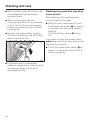
Cleaning and care
,Disconnect the cooker hood
from the mains supply before
mainentance and care (see
"Warning amnd Safety").
Housing
General
The surfaces and controls are
susceptible to scratches and
abrasion. Please observe the
following cleaning instructions.
^ All external surfaces and controls can
be cleaned using a microfibre cloth
or with warm water and a little
washing-up liquid applied with a well
wrung-out soft sponge or cloth.
^ Wipe the surfaces dry using a soft
cloth.
^ Glass surfaces can be cleaned with a
proprietary cleaning agent for glass.
Avoid:
– cleaning agents containing soda,
acids, chlorides or solvents,
– abrasive cleaning agents, e.g.
powder cleaners or cream cleaners,
and abrasive sponges, as well as pot
scourers or sponges which have
been previously used with abrasive
cleaning agents. These will damage
the surface material.
– sharp metal tools,
– oven sprays.
26
Important for appliances with
stainless steel surfaces
Stainless steel surfaces can be cleaned
using Miele's non-abrasive cleaning
agent for stainless steel, following the
instructions on the packaging.
To help prevent re-soiling, Miele
conditioning agent for stainless steel
can also be used. Follow the
instructions on the packaging.
Important for appliances with
lacquered housing
Please follow the information given in
“General notes" earlier in this section. It
is very difficult to clean this type of
surface without causing minor marks to
the surface material.
This can become particularly
noticeable with darker colours and if
there is halogen lighting in the kitchen.
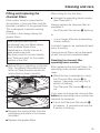
Cleaning and care
Grease filters
Cleaning the grease filters by hand
The re-usable metal grease filters in the
appliance remove solid particles
(grease, dust, etc.) from the kitchen
vapours, preventing soiling of the
cooker hood.
^ Clean the filters with a soft nylon
brush in a mild solution of hot water
and a little washing-up liquid.
Do not use "neat" washing-up liquid.
The grease filters should be cleaned
regularly (at least every 3-4 weeks) to
avoid a build-up of grease, but always
clean immediately if the Grease filter
sensor [ lights up.
Grease which builds up on the grease
filters over a long period of time can
harden, making cleaning more difficult.
,An oversaturated filter is a fire
hazard.
Avoid:
– cleaning agents containing
descaling agents,
– powder cleaners, cream cleaners or
abrasive all-purpose cleaners.
– oven sprays.
Cleaning the grease filters in the
dishwasher
^ Place the filters as upright as
possible in the lower basket, with the
short sides upright, and wash using a
65°C programme, ensuring the spray
arm is not obstructed.
^ Select a programme with a maximum
temperature of 65° C. If a Miele
dishwasher is being used, select the
Sensor wash programme.
^ Use a mild dishwasher detergent.
^ To take out the grease filters, release
the locking clip on the filters, lower
the filters 45°, unhook them at the
back and remove them.
To avoid damaging the filters or the
hob below, make sure you hold the
filters securely at all times when
handling them.
Depending on the dishwasher
detergent used, cleaning the filters
in a dishwasher can cause
permanent discolouration to the
surface.
However, this will not affect the
functioning of the filters in any way.
27
Cleaning and care
^ After cleaning, leave the filters to dry
on an absorbent surface before
replacing them.
^ When removing the filters for
cleaning, also clean off any residues
of oil or fat from the now accessible
housing to prevent the risk of these
catching fire.
^ Replace the grease filters, making
sure that the locking clips are facing
down towards the hob.
Resetting the grease filter operating
hours counter
After cleaning, the operating hours
counter needs to be reset.
^ Whilst the fan is switched on, touch
the Grease filter sensor [ for approx.
3 seconds until only the 1 sensor is
flashing.
The Grease filter sensor [ will go
out.
If you want to clean the grease filters
before the operating hours counter has
reached its maximum:
^ Touch the Grease filter sensor [ for
approx. 6 seconds until only the 1
sensor is flashing.
^ If a grease filter is inadvertently
replaced upside down, insert a small
screwdriver blade into the slit to
disengage the clip.
28
Cleaning and care
Fitting and replacing the
charcoal filters
If the cooker hood is connected for
recirculation, a charcoal filter must be
inserted in addition to the grease filters.
This is designed to absorb cooking
odours.
It is fitted in the canopy above the
grease filters.
New charcoal filters can be
purchased from your Miele dealer,
from the Miele Spare Parts
Department or via the internet at
www.miele.shop.com.
See back cover for contact details,
and "Technical data" for the model
number of the filter.
^ Before fitting or replacing a charcoal
filter, the grease filters must first be
taken out (see previous section for
instructions on how to do this).
When fitting for the first time:
^ Activate the operating hours counter
(see "Operation").
Always replace the charcoal filter immediately if
– the Charcoal filter sensor lights up
or
– it is no longer effective at absorbing
kitchen odours.
It should, however, be replaced at least
every 6 months.
Used charcoal filters can be disposed
of with the normal household waste.
Resetting the charcoal filter
operating hours counter
After replacing the charcoal filters, the
operating hours counter needs to be
reset.
^ Whilst the fan is switched on, touch
the Charcoal filter sensor for
approx. 3 seconds until only the 1
sensor is flashing.
The Charcoal filter sensor will go
out.
If you want to change the charcoal filter
before the operating hours counter has
reached its maximum:
^ Touch the Charcoal filter sensor
for approx. 6 seconds until only the
1 sensor is flashing.
^ Remove the charcoal filter from the
packaging and place in the recess
as shown.
^ Replace the grease filters.
29
Appliance dimensions
1) Cut-out for feeding through the
exhaust ducting, the mains cable and,
with ... EXT models, the connection
cable to the external motor
In recirculation mode, only the mains
cable is required.
2) Height range for appliance in
extraction mode
3) Height range for appliance in
recirculation mode
4) Installation option with spacer frame
5) Ventilation grille positioned at the top
for recirculation
6) A mains cable and, for extraction
mode, flexible exhaust ducting is
required from the ceiling connection to
the connection on the cooker hood.
Exhaust connection C 150 mm
30
Appliance dimensions
Safety distance between hob and
cooker hood (S)
The following minimum safety
distance must be maintained
between the top of the cooker/hob
and the bottom of the cooker hood
unless a greater distance is
specified by the manufacturer of the
cooker or hob:
Cooking appliance
Distance
S
Electric hob
450 mm
Open Grill
650 mm
Deep fat fryer (electric)
650 mm
Multi-burner gas hob with
a maximum total output of
12.6 kW, no burner
exceeding 4.5 kW.
650 mm
Multi-burner gas hob with
a total output of more than
12.6 kW, or a multi-burner
gas hob where one burner
exceeds 4.5 kW.
760 mm
Single gas burner with a
maximum output of 6 kW.
650 mm
Single gas burner with
output exceeding 6 kW.
760 mm
– When deciding on the safety
distance between the hob and
cooker hood, please note that a
distance of 650 mm above electric
cookers/hobs may be preferable to
give more working space under the
hood.
– Account should also be taken of the
height of the person who will be
using the hood most often. The
person should have sufficient space
to work comfortably at the hob, and
also be able to reach the hood
controls with ease.
– Please be aware that if positioned
too high, extraction will be inefficient.
See "Warning and Safety"
instructions for further information.
31
Installation
,Before installation, it is important
to read the information given on the
following pages as well as the
"Appliance dimensions" and the
"Warning and safety instructions" at
the beginning of this booklet.
This is particularly crucial when
using the cooker hood at the same
time as a heating appliance that
relies on oxygen from the same
room to avoid the danger of toxic
fumes building up.
Installation accessories
4 clamps for adjusting and securing
the extension piece
4 screws M4 x 8.5 mm for securing the
clamps
14 screws M4 x 8 mm for securing the
spacer frame and the cooker hood to
the installation frame.
4 screws 7 x 110 mm and
1 screw M4 x 16 mm for securing the
tower.
4 plugs 10 x 80 mm for securing the
cooker hood to the ceiling.
,The plugs are approved to
European technical standards for
use in concrete ceilings. Only use
the plugs in combination with the 7 x
110 mm screws supplied.
For other types of ceilings use the
appropriate fixing materials.
Make sure the ceiling is strong
enough to bear the weight of the
cooker hood.
32
Conversion kit DUI 32 for
recirculation mode (not supplied,
optional accessory). The kit contains a
directional unit and flexible aluminium
ducting with hose clips.
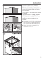
Installation
^ Draw two intersecting lines on the
ceiling a.
^ With air extraction:
– Place a section of exhaust ducting in
the ceiling and guide it through the
cross-section drawn on the ceiling b.
Exhaust ducting of approx. 700 mm
length is required between the ceiling
and the cooker hood exhaust air
connection.
– Secure the exhaust ducting to the
exhaust socket, using e.g. a hose
clip (available as an optional
accessory).
^ Place a mains cable and for ...EXT
models the connection cable to the
external motor in the ceiling and
guide them through the ceiling in the
area shown. A mains cable of
approx. 700 mm length is required
between the ceiling and the cooker
hood connectors.
33
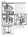
Installation
^ With a knife, release the four spacers
and the two covers from the spacer
frame c.
^ Drill four holes C 10 mm, approx.
115 mm deep, for the plugs
supplied e.
^ Use the spacer frame d as a drilling
template. Place it on the ceiling with
the arrows pointing forwards. Using
the notches on the centre lines, align
it and make pencil marks for the drill
holes.
^ Place the plugs into the holes and
insert the four screws so that they
protrude by approx. 30 mm.
34
Installation
A spacer frame can be installed
between the tower and the ceiling.
This creates a shadow which gives the
illusion of a gap between the ceiling
and the tower.
This is useful if the ceiling is not level or
is uneven.
The cooker hood is aligned vertically
with the spacers supplied. Visual
irregularities between the tower and
ceiling are then concealed by the
shadow.
^ If you wish to install the cooker hood
with the spacer frame, remove the
four inserts from the fixing holes f.
^ Mount the spacer frame onto the
installation frame g.
35
Installation
^ Hang the installation frame on the
four screws h. The holes for the
screws should be on the left when
seen from the front.
^ If using the spacer frame, place the
two covers into the fixing holes.
^ Align the installation frame to the
middle line and secure it with the
screws.
The spacers, which were removed
from the spacer frame at the start,
can be used to align the cooker hood
vertically i.
^ Holding the installation frame
securely, remove the two fixing
screws and extend the installation
frame to its maximum length j.
^ Replace the screws.
36
Installation
^ The directional unit from the
conversion kit DUI 32 (optional
accessory) is installed for
recirculation mode (UL):
– Bend the four retaining tabs on the
installation frame outwards k.
– Place the mains cable inside the
installation frame.
– Place the directional unit in as
shown l, noting the marking on the
front m.
– Bend the retaining tabs back and
approx. 45° inwards to hold the
directional unit in place n.
– Secure the exhaust socket to the
hose using a hose clip o.
– Secure the hose to the directional
unit socket using a hose clip.
– Check that the hose is securely
seated.
37
Installation
^ Push the telescopic piece over the
installation frame p:
– with the recirculation grille
downwards for extraction mode (AL,
EXT),
– with the recirculation grille upwards
for recirculation mode (UL).
^ Bend the two retaining tabs outwards
to prevent the telescopic piece from
slipping down again q.
38
^ Fit the four telescopic piece clamps
r. When the screws are tightened,
the clamps spread out and push the
telescopic piece upwards s.
Tighten the screws only until the top
edge of the telescopic piece is
evenly aligned with the ceiling or the
spacer frame.
Installation
^ Bend back the two retaining tabs t.
^ Push the tower over the telescopic
piece and bend the retaining tabs
outwards again to prevent the tower
from slipping down again u.
^ With extraction mode (AL, EXT): Fit
the non-return flap in the exhaust
socket of the motor unit v.
^ Hang the cooker hood on the
brackets, making sure that the
controls are to the front w.
39
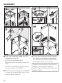
Installation
^ Unscrew both screws { from the
installation frame again.
The canopy can now be adjusted to the
desired height, observing the
permissible height ranges:
– With extraction mode:
Upwards as far as it will go,
downwards only to the A marking.
^ Secure the cooker hood with the
screws supplied x.
^ For ...EXT models only:
Connect the cooker hood and the
external motor using the connection
cable.
^ Connect the mains cable y. See
"Electrical connection".
^ Place the exhaust ducting onto the
exhaust socket z.
40
– With recirculation mode:
upwards only to the U marking,
downwards as far as it will go.
Follow the instructions in "Appliance
dimensions". Safety distances
between the hob and cooker hood
must be observed.
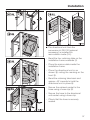
Installation
^ Raise the canopy to the desired height
and secure it with the screws |.
^ Hold the tower securely, bend back
the retaining tabs and carefully lower
the tower. The tower will locate in the
cut-out in the canopy }.
41
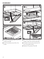
Installation
^ Remove the grease filters from the
cooker hood ~.
^ With recirculation mode (UL) cooker
hoods, insert the charcoal filter $.
^ Insert the safety screw # on the
inside.
^ Carefully remove the protective foil
from the grease filters.
^ Replace the grease filters %.
42
Connection for air extraction
Important: To avoid the danger of
toxic fumes, please observe the
Warning and Safety instructions.
This is especially crucial when using
the cooker hood at the same time as
another heating appliance which
relies on air from the same room.
The cooker hood should be installed
according to local and national
building regulations. Seek approval
from the building inspector where
necessary.
– Only use smooth pipes or flexible
hoses made from non-flammable
materials for the extraction ducting.
– When using an external motor, make
sure that the exhaust ducting is
sufficiently rigid. The external motor
can cause an underpressure which
could result in the exhaust ducting
distorting.
To achieve the greatest possible air
extraction with the lowest noise level,
please note the following:
– To ensure efficient air extraction, the
diameter of the exhaust ducting
should not be less than 150 mm.
– If flat ducting is being used, the
cross-sectional area must not be
smaller than the cross-sectional area
of the exhaust connection.
– The exhaust ducting should be as
short and straight as possible.
– Only use wide radius bends.
– The exhaust ducting should not be
kinked or compressed.
– Ensure that all connections are
strong and airtight.
– Where ducting is horizontal, it must
be laid to slope away at at least 1 cm
per metre. This is to ensure that
condensate cannot drain back into
the cooker hood.
43
Connection for air extraction
– If the exhaust air is to be ducted into
the open air, the installation of a
telescopic wall vent or roof vent is
recommended.
Condensate trap
(optional accessory)
– If the exhaust air is to be ducted into
a vent flue, the ducting must be
directed in the flow direction of the
flue.
Important.
If the exhaust ducting is to run through
rooms, ceiling space etc. where there
may be great variations in temperature
between the different areas, the
problem of condensation will need to
be addressed. The exhaust ducting will
need to be suitably insulated.
In addition to insulating the exhaust
ducting, we recommend that a suitable
condensate trap is also installed to
collect and evaporate any condensate
which may occur. Condensate traps
are available for C 125 mm or
C 150 mm ducting.
When installing a condensate trap,
ensure that it is positioned vertically
and if possible directly above the
exhaust connection. The arrow on the
housing indicates the direction of
air-flow.
Cooker hoods designed for use with an
external motor (...EXT models) have an
integrated condensate trap.
44
Connection for air extraction
Silencer
...with air extraction:
(optional accessory)
The silencer not only reduces noise
from the fan, but also sounds from
outside (e.g. traffic noise).
For this reason the silencer must be
positioned as close as possible to where
the ducting leaves the building a.
...air extraction with external motor:
To achieve even further reductions in
noise levels, a special silencer can be
fitted in the ducting system...
To minimise noise from the motor in
the kitchen, the silencer should be
positioned in front of the external
motor b if possible, or if the ducting is
long, then in the ducting above the
cooker hood itself c.
In the case of an external motor placed
inside the house, fitting a silencer
behind the external motor d reduces
the noise of the motor outside the
house.
In all modes of operation, the most
effective noise reductions are
achieved if two silencers are fitted
one behind the other in the system.
45
Electrical connection
,All electrical work should be
undertaken by a suitably qualified
and competent person in strict
accordance with current national
and local safety regulations
(BS 7671 in the UK).
If the switch is not accessible after
installation (depending on country), an
additional means of disconnection must
be provided for all poles.
For extra safety it is advisable to protect
the appliance with a suitable residual
current device (RCD).
Installation, repairs and other work
by unqualified persons could be
dangerous, for which the
manufacturer cannot be held liable.
Each wire must have a cross-section of
between 0.75 mm2 and 1.5 mm2. The
mains lead cleat supplied must be
used.
Ensure power is not supplied to the
appliance until after installation or
repair work has been carried out.
Important
Do not connect the appliance to the
mains electricity supply by an
extension lead. These do not
guarantee the required safety of the
appliance.
The connection data is given on the
data plate. (See "After Sales Service").
Ensure that this data matches the
household mains supply.
Connection of this appliance should be
made via a suitable isolator or a double
pole fused spur connection unit which
complies with national and local safety
regulations and the On-Off switch
should be easily accessible after the
appliance has been built in.
When switched off there must be an
all-pole contact gap of 3 mm in the
switch (including switch, fuses and
relays according to EN 60335).
46
This appliance is supplied for
connection to an a.c. 230 V single
phase 50 Hz supply.
The wires in the mains lead are
coloured in accordance with the
following code:
Green/yellow = earth
Blue
= neutral
Brown
= live
WARNING:
THIS APPLIANCE MUST BE
EARTHED
Activating the Con|ctivity 2.0 function
Installing the Con|ctivity 2.0
stick
The hob must be fitted with the
Con|ctivity 2.0 stick so that the
Con|ctivity 2.0 function can be used.
This is supplied with this cooker hood.
^ Please refer to the installation
instructions for the Con|ctivity 2.0
stick.
The radio connection between the hob
and the cooker hood must be activated
so that the Con|ctivity 2.0 function
can be used.
Both appliances must be installed and
operational.
You only need to carry out the
activation procedure once.
If the appliances are disconnected from
the electricity supply, during a power
cut for example, they will still remain
activated.
Important. To establish the radio
connection, the cooker hood and hob
are activated at the same time. Start
activating the cooker hood first, then
the hob.
Activating the Con|ctivity 2.0
function on the cooker hood
^ Switch off the fan, hob lighting and
hob.
^ Touch the Run-on sensor ¢ for
approx. 10 seconds until the 1 sensor
lights up.
^ Touch in turn
– the 1 sensor,
– then the IS sensor,
– then the lighting sensor I.
If Con|ctivity 2.0 is not activated, 2
and 3 will flash at the same time.
47
Activating the Con|ctivity 2.0 function
^ Touch the IS sensor to activate
Con|ctivity 2.0.
While it is searching for the radio
connection, the 2 sensor will light up
and 3 will flash.
^ Meanwhile you can start the
activation process for the hob.
Activating the Con|ctivity 2.0
function on the hob
Checking activation
To check whether the Con|ctivity 2.0
function is activated on the cooker
hood:
^ Switch off the fan and the hob
lighting.
^ Touch the Run-on sensor ¢ for
approx. 10 seconds until the 1 sensor
lights up.
^ Press in turn
^ While the cooker hood is searching
for the radio connection, start the
activation process for the hob.
For further information please refer to
the operating instructions for the hob.
– then the IS sensor,
The radio connection is established
when sensors 2 and 3 on the cooker
hood are constantly lit up.
If the Con|ctivity 2.0 function is
activated, 2 and 3 will light up
constantly.
^ Confirm activation of the cooker hood
by touching the Run-on option sensor
¢. All the indicator lights will go out.
If the Con|ctivity 2.0 function is not
activated, 2 and 3 will flash at the same
time.
^ Confirm activation of the hob.
The Con|ctivity 2.0 function is now
ready for use.
The function will not be activated unless
it is confirmed within 4 minutes.
– the 1 sensor,
– then the lighting sensor I.
^ Touch the Run-on sensor ¢ to exit
the check. All the indicator lights will
go out.
^ To check whether the hob is
activated, please refer to the
operating instructions for the hob.
If communication cannot be
established even although the cooker
hood and the hob have been
activated, both appliances must be
deactivated and then activated
again.
48
Activating the Con|ctivity 2.0 function
Deactivating
To deactivate the cooker hood:
^ Switch off the fan, hob lighting and
hob.
^ Touch the Run-on sensor ¢ for
approx. 10 seconds until the 1 sensor
lights up.
^ Touch in turn
– the 1 sensor,
– then the IS sensor,
– then the lighting sensor I.
If the Con|ctivity 2.0 function is
activated, 2 and 3 will light up
constantly.
^ Touch the 1 sensor to deactivate
Con|ctivity 2.0.
After deactivation has been
successfully completed, 2 and 3 will
flash simultaneously.
^ Confirm deactivation by touching the
Run-on sensor ¢. All the indicator
lights will go out.
^ Deactivate the hob.
For further information please refer to
the operating instructions for the hob.
To activate both appliances again,
proceed as described previously.
49
After Sales Service
In the event of a fault which you cannot
correct yourself, or if the appliance is
under guarantee, please contact:
– Your Miele Dealer / Chartered Agent
or
– The Miele Service Department (see
back cover for address).
When contacting your Dealer or Miele,
please quote the model and serial
number of your appliance. These are
shown on the data plate which is visible
when the grease filter is removed.
For the U.K.: Please note that
telephone calls may be monitored
and recorded for training purposes.
N.B. A call-out charge will be applied
for service visits where the problem
could have been resolved as described
in these instructions.
50
Guarantee
For information on the appliance
guarantee specific to your country
please contact Miele. See back cover
for contact details.
In the U.K. your appliance is
guaranteed for 2 years from the date of
purchase. However, you must activate
your cover by calling 0845 365 6640 or
registering online at www.miele.co.uk
Technical data
Total connected load * . . . . . . . . 102 W
- Fan motor* . . . . . . . . . . . . . . . 130 W
- Hob lighting . . . . . . . . . . . . . . 4 x 3 W
* For EXT models, the connected load
and extraction power will depend on
the type of external motor fitted.
Voltage . . . . . . . . . . . . . . . . . AC 230 V
...EXT models:
Length of connection cable to external
motor. . . . . . . . . . . . . . . . . . . . . . . 1.9 m
Frequency . . . . . . . . . . . . . . . . . . 50 Hz
Fuse rating . . . . . . . . . . . . . . . . . . . 10 A
Weight
DA 6690 D . . . . . . . . . . . . . . . . . . 35 kg
DA 6690 D EXT. . . . . . . . . . . . . . . 32 kg
Fan performance*
Extraction power according to
EN 61591
Extraction system C 150 mm:
Level 1 . . . . . . . . . . . . . . . . . . 220 m3/h
Level 2. . . . . . . . . . . . . . . . . . . 340 m3/h
Level 3 . . . . . . . . . . . . . . . . . . 500 m3/h
IS (Intensive setting) . . . . . . . . 750 m3/h
Declaration of conformity
Miele hereby declares that the cooker
hoods listed on the front of this booklet
comply with the basic requirements
and other relevant regulations of
Guideline 1999/5/EC.
A copy of the complete Declaration of
conformity can be obtained from the
address on the back page.
Recirculation power with charcoal filter:
Level I . . . . . . . . . . . . . . . . . . . 150 m3/h
Level 2. . . . . . . . . . . . . . . . . . . 260 m3/h
Level 3. . . . . . . . . . . . . . . . . . . 400 m3/h
IS (Intensive setting) . . . . . . . . 500 m3/h
Special accessories for recirculation
mode:
– Conversion kit DUI 32
– Miele charcoal filter DKF 12-1
51
52
53
54
8QLWHG.LQJGRP
-IELE#O,TD
&AIRACRES-ARCHAM2OAD
!BINGDON/XON/847
4EL
#USTOMER#ONTACT#ENTRE4EL
%MAILINFO MIELECOUK
)NTERNETWWWMIELECOUK
$XVWUDOLD
-IELE!USTRALIA0TY,TD
!".
'ILBERT0ARK$RIVE+NOXFIELD6)#
4EL&AX
)NTERNETWWWMIELECOMAU
&KLQD
-IELE3HANGHAI4RADING,TD
&LOOR.O3HI-EN9I2OAD
*INGgAN$ISTRICT
3HANGHAI02#
4EL&AX
%MAILINFO MIELECN)NTERNETWWWMIELECN
0LHOH+RQJ.RQJ/LPLWHG
&-ANHATTAN0LACE
7ANG4AI2OAD
+OWLOON"AY(ONG+ONG
4EL&AX
%MAILMIELEHK MIELECOMHK
,QGLD
-IELE)NDIA0VT,TD
'ROUND&LOOR#OPIA#ORPORATE3UITES
0LOT.O*ASOLA
.EW$ELHI
4EL&AX
%MAILCUSTOMERCARE MIELEIN)NTERNETWWWMIELEIN
,UHODQG
-IELE)RELAND,TD
"IANCONI!VENUE
#ITYWEST"USINESS#AMPUS$UBLIN
4EL&AX
%-AILINFO MIELEIE)NTERNETWWWMIELEIE
0DQXIDFWXUHU -IELE#IE+'
#ARL-IELE3TRAE'àTERSLOH'ERMANY
0DOD\VLD
-IELE3DN"HD
3UITE,EVEL
-ENARA3APURA+ENCANA0ETROLEUM
3OLARIS$UTAMAS.O*ALAN$UTAMAS
+UALA,UMPUR-ALAYSIA
0HONE
&AX
1HZ=HDODQG
-IELE.EW:EALAND,IMITED
#OLLEGE(ILL
&REEMANS"AY!UCKLAND.:
4EL&AX
)NTERNETWWWMIELECONZ
6LQJDSRUH
-IELE3OUTHEAST!SIA
-IELE0TE,TD
0ENANG2OAD
¬7INSLAND(OUSE))
3INGAPORE
4EL&AX
%-AILINFOSEA MIELECOMSG
)NTERNETWWWMIELESG
6RXWK$IULFD
-IELE0TY,TD
0ETER0LACE"RYANSTON
0/"OX"RYANSTON
4EL&AX
%MAILINFO MIELECOZA
)NTERNETWWWMIELECOZA
8QLWHG$UDE(PLUDWHV
-IELE!PPLIANCES,TD
0/"OX
'OLD$IAMOND0ARK
3HEIKH:AYED2OAD
"UILDING/FFICES.OSTO
$UBAI
4EL
&AX
%-AILINFO MIELEAE
)NTERNETWWWMIELEAE
55
DA 6690 D
DA 6690 D EXT
en - GB
M.-Nr. 09 733 840 / 01