1
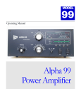
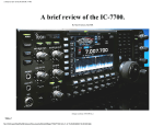
By Matt Erickson KK5DR
Copyright © 2004 M.A. Erickson, KK5DR. All rights reserved.
Introduction
Many hams have never heard of this particular model of ETO Alpha amplifier. A few have
heard of it, but have never seen one, even fewer own one.
I happen to be one of those very few who owns an 86. I'll elaborate on how I came to
acquire it later.
Only 274 of these jewels were built between December 1987 and October 1989. The last 74
units being what is known as "export" models, meaning they covered 1.8-30MHz
continuously. The unit I have falls into this final group. I personally know the person who
owns the last unit ever made, and he loves it (no, it's not me).
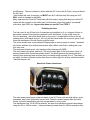
The picture of the front panel on the first page of this article shows a "domestic" model, on
which the band-switch positions are marked in ham bands, except for the 10meter band,
which is left blank and disabled from the factory.
The "export" model, has the same number of positions (9 total), but are marked in frequency
segments, including 22-30MHz position, which is enabled from the factory.
The picture of the interior, on the first page, is of a "factory-stock" domestic unit.
Some specifications:
The 86 weighs in at a healthy 66 Lbs.= 30Kg.
The box measures 7.5" H x 17"W x 15"D.
A pair of EIMAC 3CX800A7 triode tubes do the amplifying in a class AB2, grounded-grid
configuration.
A tape-wound Hipersil® 3.5kVA CCS transformer provides the power (not a Peter Dahl,
more about this later).
The 86 is able to produce 1500 watts of RF output in any mode, with no time limit.
Two plate voltages are available, 2.5kV & 1.6kV, SSB & CW respectively.
All front panel indicators are LED or LED bar-graph type.
The RF power output bar-graph full scale is 2.3kW, the grid current graph is 150mA. and the
reflected RF power reads up to 250 watts.
The Plate current graph reads up to 1.5A, and when switched, reads plate voltage up to
3.0kV
The plate current graph also can display the "tune" feature (more on this later).
The 86 uses a Pi-L output network, with a Pi type input network.
The T/R system uses PIN diode switching for high speed, silent change-over (more on this
later).
With the proper connections made, the 86 is capable of full QSK operation (more on this
later).
86 to 89
The Alpha 89, is a direct descendent of the 86, and has much of the same designs.
The similarities between the old 86 and the later 89 are many. The most obvious difference
is the outside color. The 86 is dark bluish-gray, and gray, the 89 is textured satin-black. The
basic hardware is the same, such as the cabinet, power transformer, tubes, RF tank circuit,
blower, power supply.
The PIN diode T/R system of the 89 was upgraded from the system used in the 86. I am told
that an 86 can be upgraded to become equal to an 89 for the sum of $1500 in parts. The
primary parts of this upgrade are the T/R board, and digital control board.
Recently, when the price of EIMAC 3CX800A7 tubes and power transformers had risen to
the point that they bit into the profits on the 89, Alpha/Crosslink Inc. discontinued it.
Currently, the model 99 has taken it's place, but now uses the Svetlana 4CX800's.
Busted 86
How I came to own an 86 is a twist of fate. A friend asked if I could fix a broken 86 for him,
he planned to purchase one at a low "busted" price. I told him most likely yes, so he sent the
unit to me for evaluation and repairs.
After a short while, I knew what the problems were, but I wished to do much more extensive
repairs an modifications on it, which he may not want to pay for, so instead, I purchased it
for the same amount he had paid for it, plus shipping. Poof! I have an 86, broken, but I have
one. I thought this to be good, since working examples had been selling for about $25002800 at the time. The 86 sold new for about $3995 in 1989.
The "post-mortem" evaluation on the unit revealed that the RF output PIN diodes were
completely destroyed, vaporized by something, by what, is unknown. In addition, one tube
was dead, the other weakened, but usable, so a new set of tubes would be needed.
The AC primary "step-start" system was also faulty, causing damage to the resistors in that
circuit.
There were a few other deficiencies, that I will expand on later.
PIN diode problems
The most common problem in the 86 is the failure of the PIN diode T/R system.
The problem is rooted in the devices and the SWR protection system. The PIN diodes in the
RF output line are rated at about 5 watts dissipation each without a heat-sink. The two
diodes are heat-sink mounted to handle about 10 watts each, two devices in this
configuration can handle about 20 watts reflected RF power. The forward RF power
capacity of this diode configuration is about 2500 watts. The problem happens when
reflected RF power exceeds the dissipation rating of the devices. Here is where the SWR
protection system comes into play. The SWR protection system is factory set to take the
amp off-line when the SWR hits 2.1:1, which at 1500 watts forward, is 150+ watts reflected.
You could see why the diodes would be vaporized in this condition. Under certain
conditions, on the lower frequency bands even a moderate SWR can create very high RF
voltages, which can damage the output PIN diodes.
To prevent this type of damage to an unmodified 86, the SWR reflected RF power sensor
level should be lowered to an SWR of about 1.5:1, by adjusting RP-1 on the control board.
These controls can be found inside the cabinet cover on the left hand side of the front panel.
A vertical series of blue trimmer pots are for various settings of the control board, RP-1 is
among them.
The receive PIN diodes can be damaged also, by what is known as "hot-switching". Hotswitching is when the amplifier is still in a receive condition when the exciter returns to
transmit, or vise-versa. The RX PIN diodes are much smaller, and have a greatly lower
power dissipation rating, so are easy to damage, with even a few hundred milli-watts of RF
power. If the amplifier is in a receive condition when the exciter goes into a transmit
condition, the RF can enter the RX PIN diodes, and burn them out, but there is an RX fuse
in-line with these diodes. If the fuse is burnt out, the exciter will not have good RX.
Replacing the fuse will usually fix the problem. A Hot-switch sensor will likely "trip" long
before the RX diodes will be damaged. An LED on the front panel will indicate that a "hotswitch" condition exists. Stop using the amp at this time, and make the needed changes to
prevent this condition. Details in the user manual tell how to configure the exciter and amp
for proper keying sequence.
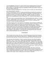
Since the PIN diodes in my 86 were beyond any repair, I decided to completely remove that
system, and install a vacuum relay T/R system. There are several web sites on the Internet,
which have this modification.
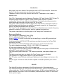
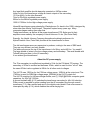
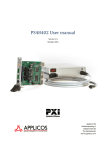
In fig.1 letter "A" points to the two vacuum relays and mounting hardware, of the modified
T/R system.
Fig.1
If you wish to do this mod, you will have to consult others that have done it, or figure it out
for yourself. The mod is not difficult for a technician with good radio knowledge &
experience in amplifiers.
If you can't do the mod, contact someone to do it for you, but don't expect the work to be
FREE!
The parts you will need are a pair of Jennings RJ-1A vacuum relays or equal type, for about
$45 each. You need hardware to mount the relays too.
The exact mod I did to my unit is proprietary so, I will not discuss it in any great detail.
Another method of repair of the PIN diodes, is to acquire a new set of diodes of much better
dissipation, and install them. High power PIN diodes of this type are not cheap!
Fig.1a shows the original PIN diode set up, the letter "A" points to the destroyed diodes.
Fig.1a
QSK?
In doing my vacuum relay modification, some would say that I have lost full QSK capability. I
say I have not. The PIN diode system has a maximum switch time of 4mS, good for about
50wpm, while the vacuum relays have a switch time of 6mS, or about 40wpm.
I ask this, how many hams do you know that do 50wpm full QSK at 1500 watts? How many
do 30wpm or even 20wpm? I think that far fewer do it, than do, and even fewer use legal
power. Going from 50 to 40wpm capacity is not a very great loss. I don't even use a power
amp when I do CW, so it is no loss at all to me. I guess the true hardcore high power full
QSK CW op will need the fastest PIN diode system available, but it's not going to be cheap.
The vacuum relay system is more that adequate for SSB VOX operation, or AMTOR.
Plate choke
In fig.1, the letter "C" points out the plate choke. The letter "B" points to an open-frame relay
that switches in or out a capacitor which alters the series resonance of the plate choke on a
given segment of frequencies. I feel that this method, although it does work, is not a very
elegant way to achieve the goal. The relay has 2.5kV across the contacts, and could arcover very easily, which could cause catastrophic damage, under certain conditions.
HV, in the presence of high RF voltages can become very erratic, better safe than sorry, I
say.
My solution for this potential problem is to replace the plate choke, and remove the choke
relay set up.
If you wish to change this system too, purchase an RFC-3 from RF Part Co., install the new
choke in the place of the old unit.
I made my own plate choke using a construction method I developed and described in an
article I wrote on amplifier building. My design uses a ferrite loaded choke to achieve very
high inductances, but avoid any series resonances within the HF spectrum.
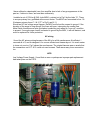
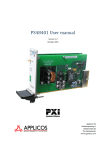
Fig.2
Fig.2 shows my plate choke design installed, the letter "D" shows the position. In addition, I
replaced L-8, C-13 to C-15, with a new choke/glitch resistor and capacitor configuration,
shown by the letters "A,B,&C", which forms an asymmetrical, low-VHF Q Pi-network.
This new network serves two purposes, (1) to prevent VHF energy from creating any feedback circuit in the tank/plate choke system. (2) to act as an HV "glitch" resistor, limiting any
HV fault current, should an HV flash-over take place inside the tubes. Capacitors "B&C" are
1000pF & 100pF, 5kV "door-knob" type, grounded to the chassis by virtue of the mounts.
The "hot" side of the caps supports the resistor "A".
The yellow line connecting at the top of the network comes from the HV power supply. The
bottom of the network connects to the base of the plate choke. The top end of the plate
choke connects to the tube side of the plate DC decoupling capacitor bracket marked letter
"E".
At this point you will notice that the plate decoupling caps are NOT original, and your right.
The original caps can be seen in Fig.1, letter "D".
My opinion on the use of "disk type" caps in high RF current/ high HV applications is a
cheap and not so reliable method. I opt for heavy epoxy encapsulated "door-knob" type HV
capacitors. I used two 1000pF @ 10kV caps, which required a new mounting bracket, that I
fabricated out of copper plate stock. These copper brackets can carry far more RF current
too. The new design is seen in Fig.2 letter "E".
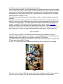
Under the sockets
Fig.3
Fig.3 shows the under side of the tube sockets, unmodified. You will notice that there is no
filament choke, I'll discuss this in detail later. The letter "C" points out the cathode choke,
which is only a 15µH @ 2A. unit, I removed this choke and replaced it with a choke of my
own design. I used a yellow mix toroid of about 5/8ths inch inside diameter. I wound #24
insulated wire on the core. The final inductance is 100µH. Toroids are self-shielding, so this
should be a very effective RF choke. My reason for doing this mod, is that the original choke
could resonate on certain frequencies in the ham bands, this mod prevents that possibility
from ever happening. The letter "A" points to the RF input coupling capacitors, which are a
pair of 0.02µF @ 1kV disk caps. A single 0.01µF @ 2.5kV silvered-mica cap would be a
good substitute. The SM cap being a more temperature stable type, and able to carry more
RF current without heating up.
The letter "D" points to the filament line. I feel that a choke is needed, even with tubes that
are "indirectly-heated" cathodes.
Here is my reasoning as to why; RF voltage potential differential between the cathode and
the heater could cause an arc-over under certain circumstances. To prevent this type of
damage, the heater is RF coupled to the cathode by a single 0.01µF @ 1kV disk cap. This
placed both at the same RF potential However RF coupled to the heater must then be
blocked from propagating back down the filament line. So, a choke must be installed on the
line.
The choke I used, is a toroid with bifilar # 14ga. Teflon® insulated wire. I used a 1" i.d. gray
mix type. I wrapped about 6 turns on the core, and the inductance is 130µH. The small size
of the core mounts easily near the base of the sockets in a corner of the plenum box.
The letter "E" points to the grid grounding tabs.
The letter "B" points to the "Tune" detector for the cathode. This circuit did not appear at all
in the main schematic, so I had to plot it all out, and find the values of the parts in it. There is
a similar circuit in the plate circuit located near the plate decoupling caps. These two
circuits form what is known as a "phase-detector" and or "gain-comparator", of which a
sample signal is sent to the control board, and displayed on the plate current bar-graph as a
"tuning aid". This feature aids the operator in tuning the amp for best gain & linearity.
This feature works well, except for 10 meters where it was a bit erratic, likely due to a nonlinear response of the detectors. For the most part, the tuning aid works well, and should
help the "less experienced" user tune up well & quickly.
Control board
This is the main control center of the amp. All the LED displays are driven from this board,
all time-delays and relay sequencing is done here too. Operational cathode bias of 9Vdc is
derived from this board also. The control board biases the PIN diode T/R system as well.
The only mod I did to this board, of which I'm willing to discuss is that of the dial lighting
behind the "Tune" & "Load" knobs. I replaced the original incandescent bulbs, which are
short-lived, and hard to get at, with super-bright jumbo LEDs. I replaced R-3 on the control
board, which is a 51 ohm 1/4 watt resistor, with a 5k ohm 1/4 watt resistor. The original light
bulb sockets can be used with the new LED, but care must be observed in the polarity of the
LED when installing it in the socket. Then, bend the leads of the LED 90 degrees toward the
front panel. Using LEDs will allow the user the choice of several colors. I chose red. The use
of LED should mean that they will effectively last a life-time.
Some strange errors were encountered on the control board. The board I have did not
match the schematic in that the part numbers were scrambled, but the circuitry was the
same. Scrambled part designators can really make circuit tracing difficult. Perhaps the board
I have is a later release than the schematic, or vise-versa. Another possibility is that it is a
variation of the "export" version, differing from the "domestic" schematic.
I took some time to trace and re-designate the proper part numbers on the schematic, this
should help me allot, later.
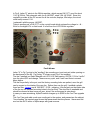
Over-drive
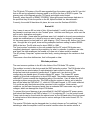
There is an LED indicator on the front panel that displays when the grid current is being
driven into over-drive. The level of "trip" on the display is set at the factory for 120mA of grid
current. This level is "hard-wired" into the bar-graph display of the grid current, it can't be
changed without moving the sense line from one point on the driver IC to another point. I
would not recommend doing that.
Fig.4
At this point, I want to tell you about the bar-graph displays, and associated driver IC's. I
found the displays to be highly accurate and ultra-fast, even faster than my RF applications
VFD outboard meter. As long as the displays are calibrated properly, they can be counted
on for accuracy and speed. For an older design, it certainly is good, even by today's
standards. Fig.4 shows all the LEDs of the front panel, some lit, some not.
Step-start trouble
Even before I was able to power up the amp, I noticed that there was a sign of a problem in
the "step-start" system. There are a pair of fuses that are rated 1.5A @ 250Vac. These
fuses had been changed to 3 & 4A. rating, this told me that this circuit had been drawing far
to much current for some reason.
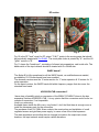
Fig.5
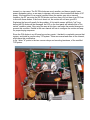
In Fig.5, the interior of the power supply side of the amp is shown, with the power
transformer removed. The letter "E" points to the "step-start" fuses. The letter "B" shows K12, and "C" points to K-11. K-11 is the primary contactor, which engages when the "ON"
switch is pushed. K-12 is the "step-start" relay, which closes after a short time-delay, after K11 closes. K-12 shorts the step-start resistors out of the circuit, when closed.
The problem with my unit, was that K-12 had worn out contacts which would not allow the
resistors to be shorted out of the circuit, which in turn caused a large current flow through
and burn up the resistors. I replaced K-12, and the resistors. I also found that the time-delay
IC was not sending current properly to K-12, so instead of replacing the IC, I built a small
RC network using a resistor and capacitor that caused about a half second delay in K-12
closure after power "ON". The replacement relay I used for K-12 was not a 24Vdc coil like
the original, all I had was a 12Vdc coil relay, but the resistors in the RC time-delay network
allows it to operate at the 28Vdc that the LVPS provides. The resistor I used was 50 ohms
@ 20 watts, with 4400µF @ 50Vdc capacitor. The main difficulty of this installation was
finding a place to put the components I found a small space to place them just to the left of
K-12 along the bulkhead.
The "step-start" system works fine now.
Surge suppression
It was a surprise to me to find that the 86 does not have any form of AC line voltage surge
suppression system.
I have suffered a catastrophic loss of an amplifier due to lack of surge suppressors in the
past so, I believe in them, and use them extensively.
I installed a set of 130Vac @ 340 Joule MOV's, pointed out in Fig.5 by the letter "A". There
is one per primary line, grounded at the mount center. The MOV's are connected to line 1 &
2 between primary fuses F-1 & 2 ("F" in Fig.5) and K-11.
Should an AC line voltage surge happen, the MOV's will shunt the current to ground. If the
duration of the surge is long enough, the fuses will open, interrupting the current flow.
Metal Oxide Varsistors are quite good about conducting only when an "over-volt" condition
is present. If enough surge current is shunted to ground by the MOV, it will self-destruct, and
must be replaced for future protection.
AC wiring
I found the AC primary wiring harness of the 86 to be a little cumbersome & inefficient. I
removed all of it, and re-designed it for a more efficient and cleaner layout. It is much easier
to trace out now too. Fig.5 shows the new harness. The original harness was so erratic that
the connections on K-11 & 12 could not even be seen. There were many loose connection
too.
LVPS
Low Voltage Power Supply; I found that an error or perhaps an improper part replacement
had taken place on the LVPS.
Fig.6
In Fig.6, Letter "A" points to the 28Vdc regulator, which was an LM-317T, good for about
1.5A. @ 32Vdc. The schematic calls for an LM-350T, rated 3.0A. @ 32Vdc. Since this
regulator provides all the DC current for all the controls, displays, and relays, the circuit
could easily exceed 1.5A.
I replaced it with the proper LM-350T.
There is another pair of LM-317T on the control board which reduces the voltage to + & 5Vdc for the digital IC's on that board. It is fed from the LVPS 28Vdc regulator.
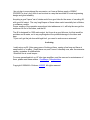
Fig.7
Fan & blower
Letter "A" in Fig.7 points to the "auxiliary" fan mounting port, and main air intake opening on
the back panel of the 86. Fig.5 letter "D" shows a new "Aux" fan installed.
The fan I installed is a Radio Shack® cat.# 273-241C Ball-bearing, 65CFM, 115Vac "muffin"
type fan, about $23 and change. These are very quiet, and I have used them in several
amps before.
The fan fits perfectly in the port, and the factory mounting holes are perfect, even the grill
can be reused on the intake of the new fan. Rather than use the grill, I installed a plastic
foam fan filter, Jameco part # 196816CF, $1.95 + shipping. It fits perfectly on the intake side
of the fan via the standard mounting holes in the fan body. The new filter is washable and
should be cleaned at least once per year, twice if the environment is extra dusty.
In case you were wondering, Alpha/Crosslink charges up to $300 for the "aux" fan upgrade
kit.
This "aux" fan mod adds much more cooling air to the system, and pressurizes the cabinet,
"force-feeding" the squirrel-cage blower that pressurizes the tube plenum. I have used this
mod on the old 76 series of Alpha amps with great success.
Now, we move to the blower, which is rated at about 40CFM under normal conditions, with
the "aux" fan installed, the flow is upped to about 50CFM, well above the CCS rating of the
tubes which is 39CFM at rated plate dissipation.
A common problem with the blower design has been excessive noise build up, most notably
in older Alpha amps such as the 76 series and the aging 86. The source of the noise is that
the blowers are mounted with an adhesive backed foam that over time decays and becomes
loose, allowing the blower body to vibrate and make contact with the metal of the cabinet.
I have a cure for this problem, which I first tried on the 76 series.
Here is the procedure: Remove the top cover, remove the tube plenum, and remove the
blower. It will be necessary to install a plug in the AC power line to the blower. With the
blower removed, it is a good time to install a plug.
Clean the chassis of the adhesive and foam. Take the blower apart to clean and lubricate it.
Wash the impeller in warm water and dish-soap, allow it to dry before re-installing it.
Next, remove the shaft, which is done by removing the end cover, and the "c" retainer that
holds it on the inner shaft. The outer shaft is hollow with felt liner inside it. Soak the felt with
high-grade machine oil or Teflon® based fine oil. Then re-assemble the shaft in reverse
order. This lubrication should be done every 5-10 years dependent on how much the amp is
used, heavy-use being the more frequent lube period.
Fig.7 "C" shows the "shipping" screws that the user is told in the operation manual to
remove after unpacking the amp. When re-installing the blower, glue two rubber grommets
to the inside panel, over the holes for these screws. The grommet should be somewhere
between 1/8th to 1/4" thick, with a hole large enough for the shipping screw to pass through.
Place the blower motor against these grommets and snug the screws down to the point that
slightly compresses the rubber. This mounting should drastically reduce the blower vibration
noise level. Rubber grommets are also used to mount the blower motor to the blower
housing. Be sure that these grommets are re-installed or replaced if needed.
Flaky switches
I ran into another problem with the front panel rocker switches. The switches were having
intermittent operation problems, and one of them stopped working in one position.
I thought of replacing the switches, but since these amps are long discontinued, it is not
likely that any replacement part could be found. I did not want to put a mis-matched switch
on the amp since the unit looks so nice and clean.
Fig.8
In Fig.8 you see an example of the panel rocker switches.
After I examined the switch, I found that the blade of a small screw-driver could be inserted
on each side of the switch, which opens the switch plastic frame enough to allow the rocker
to be removed, exposing the internal parts of the switch. The red dots show the position of
the center pivots, care should be taken not to push the blade in at these points. The blade
should be placed at points "A & B".
Now that I had removed the switch internal parts, I could see that they had become badly
oxidized.
The parts are mostly copper, so they can be cleaned. There are two small strips that move
when the rocker is moved. Behind the rocker are two spring-loaded pivot points that fit into
indents in the copper strips. The fixed contacts in the back of the switch housing are also
copper. I cleaned all of the green oxide off the strips and contacts. I used Pro-Gold® to
prevent re-oxidation or all the parts, and lubricate the rocker points. Then I carefully reinstalled the switch back into the housing, and tested its operation. They have not given me
any trouble since. It was a lot easier than replacing the entire switch, much cheaper too.
ALC on the 86
The ALC system of the 86 is not what you will find in most other amplifiers. It has no
adjustment. The level is factory set at between -7 and -10Vdc. This level of ALC feed-back
voltage will be much to high for some exciters, especially ICOM radios.
The 86 derives ALC signal from grid current flow, so it is more accurate and consistent than
RF drive signal derived ALC voltage.
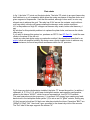
In Fig.9, "A", you can see how I installed an adjustment pot to control the ALC voltage.
Fig.9
The pot I used is a 2watt, 100k ohm, with a short shaft. I installed it into the hole vacated by
the "Key out" jack, seen in Fig.7 "B", which was removed during the vacuum relay
modifications. The pot is placed in series with the ALC line to the ALC jack, seen just below
the ALC pot.
I can't stress this topic to strongly you MUST use ALC with this amp! Not using the ALC
WILL result in damage to the tubes.
Many operators don't use ALC feed-back with their amps, saying that they can control RF
output with the controls on the radio itself, but this does not protect against "accidental"
over-drive, high SWR, etc. Anyone that does not use ALC is a FOOL!!
Finishing touches
The top cover for my 86 had a lot of scratches and oxidation on it, so I stripped it down to
bare metal, sanded it smooth and repainted it with satin black, it looks really nice now.
Prior to repainting, I did a little detail work on the cover. I chamfered the holes of the air
exhaust ports, both inside and out. Not only will this detail make the cover look good, it will
lower the resistance of the air-flow through the holes.
The cover screws were a mix-matched hodge-podge of various types of screws. I replaced
all of them with hex drive button-head screws with a black oxide finish, making the cover
look very nice.
The rear panel looked good, only needing a little cleaning with 409®.
The front panel looks great, near mint. The most unique part of the front panel is that it is
entirely covered with a protective plastic shield. The shield protects the panel paint and
lettering from everyday wear and tear that your hands would normally do to it. The plastic is
not shiny, but has a textured surface that does not reflect light like a shiny surface would do.
I like this feature a lot!
About the Power transformer
The main power transformer is the true heart of the 86. These units are high-silicon, grainorientated, steel cores (Hipersil®), wound with Teflon® insulated copper tape (flat wire).
Finally, the entire transformer was fully encapsulated in epoxy resin.
The transformer has 120 & 240Vac primary, but even the operations manual discourages
using the 86 on 120Vac mains. I have permanently wired mine for 240Vac operation only.
Any legal-limit amplifier should always be operated on 240Vac mains.
Here is a list of the transformer voltage & current outputs of the secondary:
13.5Vac @ 4A. for the tube filaments.
7Vac for the 5Vdc regulated power supply.
50Vac for the 28Vdc regulated power supply.
1250 & 1785Vac for the High voltage power supply.
Hipersil® transformers were patented by Westinghouse Co. back in the 1930's, designed by
none-other than Nikola Tesla himself. The patent expired many years ago. Many
companies began making them after that.
These transformers, as well as all the power transformers ETO Alpha used in their
amplifiers were made by the company of Harold Johnson Co Inc. (Not Peter Dahl).
Recently, the Harold Johnson Company discontinued making transformers for
Alpha/Crosslink. Now, Peter Dahl provides all the transformers for them.
The old transformers were very expensive to produce, costing in the area of $800 each.
They are very efficient, and very durable.
The white rope across the top of the transformer is for lifting, and at 45 Lbs. You need it!
The large bundle of wires is the low voltage primary and secondary. The small bundle with
Teflon® tubing on them, is the HV secondary.
It is a wicked good transformer!
About the DC power supply
The 7Vac secondary is rectified and regulated to 5Vdc for the PIN diode T/R system. The
secondary of 50Vac is rectified and becomes 36Vdc, which is used for tube "cut-off" bias,
the same 36Vdc is also regulated at 28Vdc for all other control voltages.
The HV PS uses 1250Vac for the CW/Low voltage range, 1600Vdc at the output end. The
1785Vac is used for SSB/High voltage range, 2500Vdc at the HV PS output end.
The HV PS consists of a full-wave bridge rectifier, and (7) 220µF@450Vdc computer-grade
capacitors, for 50µF @ 3150Vdc.
A ground isolated relay (K-13) switches the transformer secondary for hi/lo HV selection.
Plate current is sampled for meter reading from the AC secondary line through a small
transformer (T-2), then rectified and sent to the digital control board. Plate over-current is
interrupted by relay (K-14), which disables the exciter keying line.
RF section
Fig. 10
Fig.11
Fig.10 is the RF "tank" circuit for RF output. "D & C" points to the moving parts that should
be periodically treated with Pro-Gold®. The stock plate choke is pointed by "A", and the HV
"glitch" resistor is "B".
Fig.11 shows the "tuned input", consisting of silvered-mica capacitors, and toroid coils. The
band-switch of the input network should be treated with Pro-Gold® also.
WARC bands?
The Alpha 86 is fully-operational on all the WARC bands, no modifications are needed,
provided the 10/12 meter bands have been enabled.
The domestic version uses the 15 meter section for 17 meter operation & 10 meters for 12
meter operation.
On the export version, the WARC bands fall within frequency ranges that also cover the
standard ham bands.
4CX800/GU-74B conversion?
I have done a feasibility study on conversion of the EIMAC 3CX800A7 tubes to the less
expensive Svetlana 4CX800/GU-74B. It is my opinion that this conversion would be far too
complex & expensive, if not impossible.
Here is my reasoning:
Available space inside the 86 is very, very limited. I don't feel that there is enough room to
install the necessary parts for the conversion.
The purchase of two GU-74B's & two sockets, the construction and installation of a well
regulated screen and grid-bias power supply, to name a few of the initial expenses.
The plate impedance would allow that no changes be made in the output tank circuit,
however, the input network would require radical alterations.
I do not plan to even attempt the conversion, as I have a lifetime supply of EIMAC
3CX800A7's, plus I don't think it can be done in a way that would be of sound engineering
design and good reliability.
Acquiring a good "spare" set of triodes would be a good idea for the owner of a working 86,
with good full output. The very long lifespan of these tubes would essentially last a lifetime,
or enhance a resale.
Proper reading of the operation manual and strict adherence to it, will help the user get the
maximum life out of the tubes, and the 86.
The 86 is designed for 1500 watts output, but it can do a good bit more, but that would be
pointless and a waste, not to say anything about the potential damage to the tubes and
amp.
"If you can't get the job done with legal-limit, you need to work more on antennas."
In closing
I really enjoy my 86. After many years of looking at them, seeing a few here and there at
swap-meets, or on eBay, I finally have one, and I know it intimately now, after the extensive
repairs, upgrades, & modifications.
I think this one is a real keeper…
For more generalized info on HF tube type amplifiers, and the care and or maintenance of
them, please read these articles. GoodAmps, & Ampbuilders.
Copyright © 2004 M.A. Erickson, KK5DR. All rights reserved.