1
MODEL NO.
298.586190::
Foi _ q_iick :service or repair, take your Outboard .....
Motor t o any: Sears Service Unit throughout
the
U.S. and Canada.,
Each Service Unit is staffed
by trained
technicians,
using Sears approved
.
parts and repair
procedures
to ensure that we .
meet our pledge to youJ'We
service what we
Sell." Refe_ to the Iocat telephone directory
for •
the Sears Unit nearest you,
.
FULL ONE YEARWARRANTYON
OUTBOARDMOTOR
For one year
this
tions
will
plete
mode!
replacement
identification
number
parts
for
Plate
for
when requesting
your
outboard
the'chin-
"
service or
motor,
mercial
WAY£
GIVE
REPAPR
THE
TION! :
::
the
parts
You
FOLLOWING
from.
applies
for
order
will
need
be
are
not
tronic
AL-
trollin
or
the
is used
only
oui_ -_:
for
com-
this
thirty
war-
days
from
9 motor
to the
in the
Warranty
by simply
Or etec-
motor
nearest
United
iS valid
Sears
States
in country
Or
of
purchase.
warranty
rights,
and
rights which
gives
yoLf
vary
you
may
specific
also
have
legal
other
from state to state.
SEARS,ROEBUCK
AND CO.,
DEPARTMENT
698/731A
locally,
transmitted
Center for:
is avail_able
out,board
center
Canada.
INFORMA,
stocked
in
purposes,
Service
returning the
3. Part Name
4, Quantity
electronically
to a Sears Repair Parts Distribution
expedited
handling,
your
motor
rental
Warranty
This
_:1, Model:Number
Part Number
If
PARTS,
material
appear
free of charge,
or
service
ORDERING
the
Sears
the first, day of use,
.....
WHEN.......
in
followed,
in
which
Sears
Tower. Chicago_ lL 60684
SEARSCANADAINC.
::
222
Jarvis
St.
Toronto,
:
all instruc-
detailed
are
defects
the outboard
ranty
motor.-
All parts ]isted herein may beordered
ahy Sears, Roebuck and Co.
,
when
procedures
Manual
repair
board
first day of use of
motor,
workmanship
If
the
and
Owner's
HOWTOOROER
.EPAmPARTS.....
Refer 'to
from the
outboard
Ontario.
canada
:
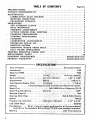
TABLE OF CONTENTS
SPECIFICATIONS
P se No.
..........................................
I
OWNER'S RESPONSIBILITY
...........
_ • , .............
:.......
2
MAINTENANCE
..........................................
4
"LUBRICATION
GEAR HOUSING
4
MUFFLER
INSPECTION
• .....................
4
PROLONGED
STORAGE
.................................
4
OPERATIONS
.............................................
4
NEW AUTOMATIC CLUTCH
• ..................
4
BOAT MOUNTING ..................................
.......
5
STEERING ADJUSTMENT
.....
...........................
5
2"CYCLE ENGINE FUEL MIXTURE
.........................
6
STARTING PROCEDURES_
. .................................
6
STOPPING PROCEDURES
............
. .........
.........
6
FLOODING
...........................................
7
CARBURETOR
ADJUSTMENTS
.............................
7
PROPELLER SHEAR PIN .................................
7
IGNITION SYSTEM
.............
, ..........................
8
REMOVING MOTOR FROM BOAT
• ........
8
SALT WATER OPERATIONS
..............................
8
TROUBLE SHOOTING CHECK LIST
..........................
9
REPLACEMENT PARTS ....................................
10
ORDERING PROCEDURES
......................
Outside Back Cover
PRODUCT WARRANTY
Outside Back Cover
SPECIFICATION:::,
Horsepower
...............
..i,:/_!_;,:/. o. , . , . Air Cooled 2-Cycle
'::"_:_;:_'-_,':?,_
:_i ; ::"' .... "..............
3.00
"
Propeller Via. and Pitch .....
; (!82mm x i30 mm) .. _7.177 x 5.127:
Lub. (Gear Hsg.) ...................
.... ::,:..
i;i_ : ,:_.....
. ..... _ ......
SAE 90!
Fuel Mixture , .,
50 to 1 ratio Of regula,_-gr_ad_gaso
ine t62-cycle outward
lubricant or its equivalent BIAcertified!TC_W:2_ycle outboard lubridanti
Steering ........................
,.,,
=.........
243
Pivot Steering
r
Type of Engine .................
...........
'
_i _
•_
•
:
IMPORTANT
• •
:
i
Owner's
.::.
:
BE SURE TO READ
OPERATING
SAFETY
Learn
2.
U,S. Coast Guard
3,
4:
5.
and
_!
:):
HH_
Check List
AND DO THE:FOLLOWING
BEFORE
YOUR OUTBOARD
MOTOR
:......_
the
t_oatingilawsof
reguMtions
an approved
II • ..................
:: • •
: i::H-:
req0i_:e the
life-Vest,
:
the
U.S, Coast
following:
tYPe 1,2
state.
Ic.:at:author:
"
or 3, Personal
:
:
Guard,
a,
Provide
b.
person in boat. (Encourage passengers to wear them,)
If the boat exceeds 16 feet, also carry a type 4, throwable
Device.
"
Flotation
7
::
Device for each
Personal
•
Flotation
Do not fill fuel tank with motor
running or near any flame or lighted smoking
material.
_ ,, ::
When loading boat distribute
the load evenly , keep the 10ad low; don't overload;
don't stand in a small boat. Take weather and water conditions
into account.
Do not permit
persons to ride on parts of the boat not designed
Standing, bow riding and seat back or gi_nWale riding can be especial|y
:i: OWNER'S
: 6.
• 7,
observe
:
i
and Operat_gSafety
CHECK,LIST
1.:
;:
: ;:
Responsibility
•
RESPONSIBILITY
for such use.
dangerous. "=
:
Read owner's manual before running your new outboard
motor,
Before starting, make sure your motor'
is!:seCurely mounted to boat
•
transom
:
with a
:i safew Chain: Tighten clamp stead handies_0:relyby
hand,
8. Be sure to have pliers, screwdriver,
spare'sp_tPk plugs, wrench, shear pins and cotter
_ins in boat whenever leaving shore,
9,
Be sure t_o have an adequate supply of fuel (carry only inan approved container) on
:_ board;
Use a good grade of regular gasoline with proper mixture,
as cited in the
Specifications.
10. Occasionally
check to be sure clamp stud handles on transom mounting
bracket are
11.
tight.
IN CASE
SING
12.
_:!!i 13,
14.
OF AN
THE
STOP
EMERGENCY,
BUTTON
THE
(IF
ENGINE
SO EQUIPPED)
CAN
BE STOPPED
OR
PLACING:CHOKE
BY DEPRES:
KNOB
::÷_
IN
Keep an alert i6ok0ut,
Serious accidents have resulted from failure to use eyes.
Keep
gh'tlngPOSITION
and lifesaving
equipment
in good €ondition
and readily accessible -FULL firef
CHOKE
........
at all times,
:
. :
Good housekeeping
is eveh more important
afloat than ashore: Cleanliness dimin;
ishes the probability
of fire and tripping
: TIPS FOR TRAILERING
hazards.
OR AUXILIARY
USE..... - ..... _
15.
When launching
or loading boat on a trailer, place your Outboard
motor
in tl_e
tilted
storage position,
Also when tra lering your boat and outboard
mot6r, keep
outboard
motor
inupright
(vertical)
position
on:the
boat transom.
Outboard
::motors,transp0rted,
across :rough roads in the "tilt"
position could cause trans0rn
...... iidam_;:br
::m0ul_tirig brackets to break off, losing your motor.
If motor_must
be:
iltra[i_b_i!!i_!_itiW!i:posJ:tli0n,
a Short
i_o_
ibrack"t
and the:mot0i::lag.
i•again:st :the, 2 x:4: to ,prevent
!:takbn: ifOSing
i: 'i
themoto
r asan
length of 2 x 4 should' be placed between the"
The motor leg shoiild then be firmly tied down
any possible
auxiliary
g motol_ as_an:auxiliary
power
motor:brackbt
is recommended.
damage.
power
source,
•
Similar
precautions
source for a sailboat
should
o(Powe¥
be
_oat, I
the use of an auxi[iaryadjustabie
:
•
-:
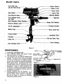
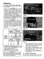
MAJOR PARTS
Fuel Filler Cap
a.d Air VentScrew
StarterHandle
ChokeLever
Power Head
Stop Bullon
Spark Plug
Fuel Shut-offValve
-Steering Handle
Fuel SedimentBow]
and Filler
Dual AutomaHc
Clutch
ClampStudHandles
/
ReverseDrivingLock
Brackel
Tilt Pin Adjustment
MufflerPipe
DriveShaft Pipe_
ExhaustOutlel
CavitalionPlale
Propeller---Fill and Drain Plug
CollerPin
Gear Housing
-
Figure
I
MAINTENANCE
1.
FEATURE
a.
This outboard
motor
has special design
features as shown in Figure 1,
Your selection of our Marine Products will
b.
INFORMATION
provide you with many hours of enjoyable
boating.
To assure your complete
satisfaction on the investment
you have just made,
we ask you to read this manual thoroughly
before going afloat.
Acquaint yourself with
the particular
areas of operation
on your
outboard
motor: as you read, the step-by-step
procedures.
Keep in mind maximum
Performance
is achieved only wher] the owner
or operator
is completely
familiar
with the
c,
operating instructions.
Periodic servicing
will
recommended
that you
: .....
be required,
consult your
Service Center when service
We will be happy to extend
and assure prompt service.
. Figure.2
it is
Sears=
is necessary,
our facilities
Figure 3
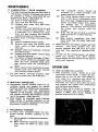
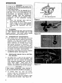
MAINTENANCE
2.
LUBRICATION
a.
The Gear Housing hasbeen pre-lubricated
at
the factory;
however, the grease level should
be checked as follows
using SAE 90 out-
_
GEAR
HOUSING
board motor grease, tSee Figure 2).
(1)
Prior to initial operation.
(2)
After first four {4) hours of use.
(3)
Recheck
after every fifty
(50)
b.
• _(3)
(4)
(5)
(6)
c.
3.
a.
For
with
(6)
Replace plug and washer. Be sure plug
is tightened securely.
To achieve complete
drainage of',lubricant. remove cotter pin, propeller
and
shear pin from propeller
shaft; also_
gear housing cover by Unscrewing
2
bolts,
c.
When lubricant
has completely
_ra_ned,
repJace parts and refill gear housing
using filling procedure above,
best results, lubricate
propeller
shaft
tithium grease every 30 to 60 days.
by uncarbon
build-up ins_i.de the muffler
inlet and outlet,
the
exhaust
port
andi:the
combustion
carbon
power
b_ Care: should
be exercised
while cleaning
.away
carbon
tO prevent:i scratches to the
surface of the engine components
and dropping carbon inside of crankcase.
4.
(5)
b.
"chamber
of the cylinder; ,:Excessive
will prevent drawing
the maximum
out of the engine. [see Figure 3).
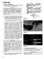
PROLONGED
STORAGE
a. Tot store your= outboardlonged ,storage,
prepare
lows:
motor
for pro=
outboard
as fol-
(1) ' See paragraph on stopping
(Ref. 10)
' '
(2)
When removing outboard
boat,
unit.
a_tow all
water
to
(4)
mounted
on a stand vertically
power head up for storage.
Pull starter handle slowly until
hours
Remove
drain plug and washer, then
insert
nozzle
of gear lubricant
tube
into hole.
-Squeeze tube until
lubricant
is forced
out around tube.
MUFFLER
INSPECTION
Periodically
remove '_miJffler coverscrewing
screws and
inspect for
The
outboard
motor
should
be
with
resist-
ance iS felt due to compression
pressure, then stop. Release starter tension
slowiy to prevent
engine from revers-
running time.
(4)
Replace with new |ubdcant
at the end
of your outboard
motor season.
This
is important,
as it removes any water
from
the gear housing
and prevents
possible corrosion to internal parts.
To Check, Drain or Fill gear housing, follow
these steps:
(1)
Position outboard
motor upright,
(2)
(3)
procedures.
motor
from
drain
from
ing
rotation
due
to
compression
pressure,
This position will close both.
the
intake
and
exhaust
ports
.for
storage.
Drain and fill gear housing as outlined
under Lubrication
of Gear Housing.
|Ref. 2)
Wipe exterior
completely
with
fresh
water cloth and then apply light coat-
ing of oil,
When starting a new season, always use fresh
gasoline.
Last year's gasoline may
have
varnish deposits that will plug the carburetor jets. thus requiring a complete
overhaul.
To plan for the coming season, we recommend
you
contact
your
Sears
Service
Center before the new season for any service
repair work required,
OPERATION
NEW
New
AUTOMATIC
CLUTCH
automatic
clutch.
Based
on
a dual
centrifugal
clutch design, it allows the outboard
prop to turn at very sJow speeds or
even come to a complete
stop while the
engine continues
operating
efficiently.
It
eliminates
the need to shift gears by hand
and prevents the engine from
overheating
and stalling at slow speeds.
When engine starts, motor
is neutral.
As
throttle
increases, sub clutch engages.
At
approx.
6 MPH,
main clutch
ehgages to
provide direct drive for cruising.
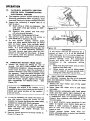
OPERATION
6. BOAT
a. Mount
MOUNTING
the motor
transom
Hand
(stern).
tighten
on the center of the boat
(See Figure 4).
CAUTION
transom
bracket
and clamp
stud handles simultaneously.
Do not use a
wrench or any other device that would
Cause damage to brackets.
Occasionally
:check tO be sure lamp stud handles on
transom
mounting
bracket
are tight.
(See Figure 5).
!,
20,7""
b.
To obtain
the best performance
from your
outboard,
the following
boat transom speci_
fications
are recommended:
(See Figure 4).
Transom Angle {See View 3):
....
. . . ....
12 to 15degrees
Transom Height (See View 4):
20.7 inches
c. The angle of the motor
column
is easily
adjusted
changing
View 4
•
.
?
by removing
the Hitch Pin:and
the Tilt Lock Bracket
Pin in the
five
(5)
different
angle position
holes
_ located on either side of the right or left
Transom
Mounting
Brackets,
Each angle
position
elevates
five
(5) degrees.
Try
center hole position
d.
first.
(See Figure 6).
To find the correct angle
test run at full
throttle
positio n, make a
with your
usual
loading in the boat,
Always stop motor to
change the Tilt Lock Bracket pin_ The c0r,: rect angle position
will
have your
boat
traveling
the-stern,
with the bow
but should
H
Figure 5
slightly higher than
not porpoise (bow
_:
rises and falls rapidly and continuously).
Be
sure Tilt Lock Bracket Pin is always pushed
completely
through
both Transom
Mount-_
ing Brackets and Hitch Pin is secured,
----------------If the motor
WARNING
column is tilted
ward, the boat
cavitate
at full
is likely
throttle,
too far out*
to porpoise
which can
or
be
dangerous because a cross wind or a wave
could suddenly .deflect
the boat into a
dangerous -turn.
Ale00
if the
motor
column
of-the
is tilted too fa T inward, the bow
boat wilt dig in, which can: be
dangerous
When
crossing.a
rough _water,i '' Do
St0_age position,
FigiJre 4) _.
e.
Secure
motor
to boat
Chain not included
wak e or fin
not runmotor_
(See -View.:1
with
with motor.
in, the.
and 2,
_,
Safety
:Chain.
.
Figure 6
7.
STEERING
Tighten
ADJUSTMENT
steering tension
for desired
bolt
steering eff0rt.(See
using a spanner
:
Figure 6).
_
There
is a possibility
of losing
backed out too far,
CAUTION
bolt
'
if
I
OPERATION
8. 2-CYCLE
ENGINE
FUEL
MIXTURE
Use a good grade of regular gasoline. (See mixing table below.)
CAUTION
Always use BIA certified
TC-W oil in the
50,1 ratio.
Failure to do so may result in
excessive
spark
plug
fouling,,
piston
scoring, or bearing failure.
Oonot
unde[
any circumstances,
use multigrade,
such as
10W-30, or other automobile
oils; •
if BIA certified
oil is not available,'use
an SAE 30 or 40 2-cycle or outboardoil;We reserve the right to refuse warranty on
parts
which are
damaged
when. using
improper
fuels or lubricants.
....
Figure 7
.WARNING
Gasoline is highly f!amm;_ble.
Always mix
in well ventilated
area; : Do not fill tank
with motor
running,
n0r= near any flame
or while smoking.
Be sure vent screws
and filler
caps on tanks are finger tighte:
ned when
trunk of
transporting
gasoline in the
your
automobile
to prevent
explosion.
Figure 7A
U.S. Measure
-::i
;
E:
Regular
Gasoline
_.!':
:
to be added
In Gallons
In Pints
1
FUEL
MIXING
i: TABLE
I. : 50:1
3
5
6
i_.
....
: '
':
In Oz
0.16
2.6'
0.48
0.80-_::
''''_ .......r
.:. 7.7
.....
I: MIXTUR
E
: "
=
Regular
Gasoline
AmoUnlof!:oil:
!
In Liters
In Liters
.
1
0i02 ;: :::
Figure 8
e.
,
9,
a.
': :,20
'
:
retract
STARTING
PROCEDURE
(See Fig;7&
7A)
Open air vent screw located on fuel filler
f.
cap by turning counterclockwise,
b. Open fuel shut-off valve.
c. Open throttle- grip to hatf throttle.
do Move choke lever to "On'* position.
g.
WARNING
When
stetting
outboard,
the
boat
Pull starter handle slowly until you feet
starter
engage.
Then pull with rapid
motion
and allow the starter cord to
slowly.
(See Figure 8).
After engine has started,
gradually move
choke
laver to "Off"
position
while
warming up the engine.
Let engine
idle for
approximately
3
minutes before moving throtUe grip to
"Fast"
position.
wilt
move with a sudden burst of speed. Make
sure you are well seated so as not to lose
your balance with e fast start,
10.
STOPPING
PROCEDURE
To
stop engine,
move throttle
position
grip
and press stop button,{See
to
"Slow"
Figure
7A)
OPERATION
WARNING
In case of an Emergency, the engine can
be stopped by moving the Choke Lever to
Full Choke Position.
if the motor will not be operated
for a
period of time, if it is to be removed from
the boat, or if it is to be tilted up, we
recommend
the
following
practice
to
prevent
spitlage
from
the
carburetor
_
throat
and bow!
and to prevent
gum
formations
in
the
carburetor
during
storage:
1,
Close fuel
shut-off
valve
and air
vent screw at fuel filler cap.
Al!ow
motor
to run at idling speed
until
it stops of its own accord,
indicating
the
carburetor
has run
dry,
2.
1%
Figure 9
FLOODING
To clear engine of excess fuel, move choke lever
to "Off"
position
and throttle
grip to half
throttle
position.
Pull recoil starter
handle
until engine starts and continues to run.
12.
a.
CARBURETOR
Your
motor
Figure IO
ADJUSTMENTS
has a idle adjusting
screw and
the idle speed has been preset at the factory.
However,
you may need to adjust the idle
speed using Idle Adjusting
Screw. Turn the
Screw clockwise
to increase motor
speed .......
and counter clockwise
to decrease it. The
idle speed adjustment
must be done with
' throttle
grip at ful closed position and the
idle speed should be as low as possible while
-
: the engine runs steady.
b,
.'
Periodically
ing Sediment
i3,
Bowl.
PROPELLER
PIN
a.
The
(See Figure 9)
check filter for dirtby
unscrew*
(See Figure 12)
SHEAR
PIN
"
& COTTER
HOLDER
Shear
Pin is used for
the
purpose
of
protecting
the Drive Train and Gears.
The
Shear Pin wil! not prevent
the propeller
from
becoming
damaged when striking an
under water
object.
When shear I pin is
broken,
the engine will continue
to run,
however, the propeller will not be rotating.
Stop engine immediately
after
shearing
CAUTION
pin to avoid possible
damage to the engine.
b.
To replace
shear
remove cotter pin
propeller.
c.
7
pin,
with
(See Figures
shut
pliers
off
motor,
and slip off
10 & t 1).
Replace with new shear pin located in shear
pin and cotter pin holder.
(See Figure 12).
Figure 12
Fl_Adjlsti!g
_rew
OPERATION
14.
FLYWHEEL
¸
MAGNETO
SYSTEM
WITH
ELECTRONIC
The magneto
following
sisterized
IGNITOR
ignition
system consists of the
component
parts: Flywheel. Trar_Electronic
Ignitor and Ignition Coil.
Inspect the following
if
hard to start:
(1)
Spark plug as often
sure spark
tO.6mm).
C,
d.
15.
a.
IGNITION
.TRANSISTERIZED
plug
engine
fails or
is
CENTER
as necessary.
gap setting
supply and
be open.
is .025"
fuel
(2)
Gasoline
fuel
off valvesho01d
{3)
The
Carburetor being starved of fuel.
correct
spark plug for this motor
Figure 13
shut-
is
NGK 8MR-6A
or Campion RCJ-8,
To
test
ignition
system,
remove
spark
plug and pl_E',ce against bare spot on meta_
part of motor
away
from cylinder
spark,'
plug hole and then pull starter cord several
times.
If a spar k bridges the plug gap. the:
magneto
is in good operating
condition.
The high tension lead wire must be con-:
nected to the plug for this check.
If there
is no spark,= have the ignition
checked
at
your Sears Service Center.
REMOVING
Always
shroud.
MOTOR
tilt motor
DO NOT
FROM
Figure
If
BOAT
by lifting
on rear of
PUSH DOWN
ON THE
upward
direction
until the propeller
clears
the transom.
Hold the motor upright long
enough to allow alt_Water to drain from the
exhaust pipe, When yop find it difficult
to
hold the;motor
uprigllti tighten the Center
Bolt increasingly
for desired effort.
(See
Figure 13).
_,.
possibleto
WARNING
burn your
one
be necessary
side
before
.16.
To
.......
to rotate
the
transom
tO remove leg from
.... installed on boats with thick
the motor
motor
on
WARNING
will not be operated
it Stops of its own
caring the carburetor
for
a.. Always
tilt your
when not in use.
b. Never leave the
motor
to
lower
follow
"
.
out
unit
of
the
steps
water
in salt-water
overnight.
Wipe exterior completely
with fresh water
cloth and then apply light
coating of oil.
Lubricate
propeller
shaft occasionally
with
a waterproof
type of lubricant
(Lithium
Grease), thus enabling
the propeller
to be
the
c. Always
carry
outboard
with
the engine
above
the lower unit'to
prevent moisture
from
entering • the
engine
through
the
exhaust ports.
handle
indi-
the
removed easily.
the water when_i
e,' It is good practice
when opereting
transoms;
.
1
water to inspect your .motor daily
:d_ Steering handle serves as carrying
.... shown in Figure 14.
a
SALT
WATER
OPERATION
" .:
materially
increase the life of all exposed
finishes;
c.
accord,
has run dry.
parts and decorative
indicated
below.
hands on the engine:
tilting
motor
until
d.
It may
the
storage:
1.
Close fuel shut-off valve and air vent
screw at fuel filler cap.
2.
Allow motor
to run at idling speed
"
biock and upper portion
of the cotumn.
Although'
the engine is air cooled, it is
Do not touch.
b.
14
period
of time.
if it is to be removed
from the boat, or if it is to be tilted up_
we recommend
the following
practice
to
prevent
spil|age
from
the
carburetor
throat
and bowl
end to prevent
gum
formations
in
the
carburetor
during
STEERING
HANDLE.
When removing the
motor from the boat. raise the outboard
i;n
,_ ,;
BOLT
Be
as
_
_
: f.
apply
a
part or
rosion or
Always
tically,
before
in salt
and to
light
coating
of grease to
area that shows evidence
of
rust,
remove
motor
from
boat
allowing water to drain
tilting the motor.
any
cot-:
ver-
from column
TROUBLE SHOOTING CHECK LIST
*Take
Fuel Tank
your
outboard
motor into any one of over
2000 Searz Service Units.
X
X
X
X
X
X
Fue
L ne KZnked or Pin_;hed
X
X
X
Fuel
Filter
X
X
X
vent
Screw On Fue] Tank
X
X
X
X
X
X
X
X
X i' '
incorrect
X
X
X
X
X
Carburetor
X
X
X
X
X
X
X
X
X
X
"" X
X
X
'
'i"
X
X.
x
.x"
x
X
X
X
X
Fuel-Oil
X
" ' '
X
X
•
×
X
•
='
'
Cap Closed.'
*
Out of Adjustment
•
'
Spark
Defective
or Fouled
Magneto
•
'
'
Ptug
Spark
Plug
,,i,.
,
Does Not Jump, Spark
Out of Time
: o
Transisterized
Electronic
Weak' 'Ignition
Coil
Spark
"
Dirty
Mixture
• Defective
.... Engine
X
Fitter
Passages Clogged or
Type
Spark
"'
or Clogged
Flooded
Wrong
x
X
Dirty
Carburetor
Engine
X
"
'
Empty
Piug Lead Wire
PJug Gap
:_
.
...
_gnitor
'
,
'-
out of order
"
_ -
:
Not Secured
* •
:' ' "
*
'
'_
• *
X
,
.1
.
X
X
Propeller
:
IMPORTANT
MODEL
NUMBER:,
SERIAL
NUMBER
Bound
High Tension
by Foreign
Lead-Salt
Objects
Water
(Fishing
Build
INFORMATION
Line. Weeds.
Etc.)
Up
IDENTIFICATION
PLATE
298.586190
DATE OF PURCHASE
INSURE
Many
insurance
InsuraNce
boat
offer
and
own
etc.,
as well
ble.
agen t
protection
outboard
your
damage
YOUR
companies
as
and
for_
be wise
further
Allstate
to
for
information
theft,
property
others
to contact
your
covering
damage,
insurance
injury
for
Insurance
againstr
liability
pe_'sonal
It would
including
contracts
engine_
equipment
ENGINE
is availa-
your
insurance
about
adequate
protection.
OPERATING?:LOG
DATE
9
NO.
HRS.
USED
GALS.
FUeL
USED
DATE
NO: HRS.
USED
GALS;
FUEL
USED
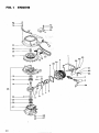
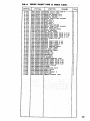
REPLACEMENT PARTS _
FOR!,,,_._
MODEL No.298.586190
IO
FIG.I
ENGINE
_
79_
1
3O
65
75
66
74
48
80
5
86
299
8
-27
|'!
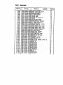
FIG.I
ENGINE
REENo,
_:o0i
P.P.No;
PARTS
NAME
o10-1o201-2oiCYLI'NHER:-SH2OUP_
1-002
157_04000-900
1 ";003
018-00546-200
1._004
002"10200"802
1-005
OI_-I0200:ZOZ
040-I0100-2_0
1-006
t°-007:
041_10100-201
t-OOE
039-02000-201
1-009
031-10100;210
037-10100;200
1-010
1-011
046-10242-800
1-012
068=02000-200
. _1-014
999-01020-300
1-015
996-66173-000
11017
" 999-62101-004
1-020
1:59-21401-871
1-024_
07!-02007-2]0
07.1.;02007-220
!-024
1 ;024
071_02007-230
1,_024
07I=02007-240
' _ 1-o25 999-61620_200
1-028
999-60153-000
1-027
o9o-lo2oo_202
,1-029
072-.I0242_900
:107-20751-801
:: 1-031_ :?:.198;01046_g00
.... 'I"032
155-21717-801
1-033112_10242-200
1-038
; 055:_02501-200
1-039.,
I 99I_00100_001
1-048
19U-11109-200
1-055
256-01046-200
1-065
g90_11050-102
1-006
1992-0!050-04!
1-067 :l 990-11060-302
1-068
: ] 992-10060-042
090_11040-162
•
_ 1-070.:
1_074
990-11040-182
, 1_075
992-10040-042
: 1-078
990-11060-252
1-079
_92-I0060-042
.!
1,080
992:10060-042
l:'OG 1
991-01060-021
:'_.
I "085
992-01050-041
l:-OGU
090-11050-102
1:1o3.... 992--ri0040--042
SPARE PLUG CAP ASS'Y
SPARS PLUG BHRSA
CYLINDEZiCONP.
"
CYLINDEI:_GASKET
PISTOH!.21B6
PISTOH R:IHO
PISTOH PIN CIRCLIF
_ISTOH
::
PISTORPIH
IOX35
.
CEAHK"SHAFT COHP.. " .
VOOD-_UFF KEY 3Xi3X5
5ALL BEARIHO e6203
OIL SEAL 17307
HEEDL2 BEARING FIOIOB
rIGHITOR TTI-IE
:CRANK SHAFT SHIK o;|o
CRAEK.SHAFT SHIX.O.15
CRA#ESUAFT SHIH0.20
CRAHS SHAFT S9IH 0.30
BALLBEARING
16202
_IL SEAL 15307
_RAHE.CASE GAS[ET
_RANI:CrASEASS'y
IGBITION:COIL
CORD"CLAHP
ASS COHP.
Y
MAGNETO ROTOE:'COHP._
FAH:CASE
:
FLYVBEEL VASUER
FLYVHEEL HUT 10
CO_D CLARP L
SPAR[ PLUG RUBBER COVER E
SCREH 5X10
VASHE_ 5
SC_EV 6X30
S.VASHEK 6
SCREV 4X16
SC_EU 4118
S,UASGER 4
SCR£9 6X25
S.HASHER 6
S,VAS_E2 6
NUT 0
..
VASHER 5SCREV 5X10
S.VAS_R
4
O'ty
1
!
1
I
1
1
1
1
t
1
1
1
1.
1
V
V
V
V
I
1
I
t
!
1
1
1
1
1
1
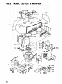
FIG.2
TANK,
CLUTCH
& MUFFLER
102
45
42
\
\
31
15
61
56
55
16
13
28
29
24
Z2
78
3O
13
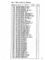
FIG,2
TANKt
REENo.
2-002
2-003
2-004
2-005
2-006
2-007
2-008
2-009
2-010
2-0It
2-012
2-013
2-014
2-015
2-010
2-017
2-OIG
2-019
2-020
2-02I
2-022
2-023
2-024
2-025
2-026
2-027
2-028
2-029
2-030
2+031
2-033
2-034
2-035
2-038
2-037
2-038
2-030
2-040
2-041
2-042
2-043
2-044
2-04S
2-04H
2-04?
2-048
2-049
2-050
2-052
2-053
2-054
2-055
2-050
2-059
2-060
2-001
2-082
2-063
2-004
2-085
2-066
2-087
2-068
2-069
2"070
2-071
2-072
2-073
2-074
2-075
2-070
2-077
2-07E
2-100
2-101
2-102
2-103
2-104
CLUTCH
P.P.No.
595-35100-D02
630-35500-200
300-35505-200
305-35500-200
650-00801-200
82D-10201-20
790-1020t-210
788-10200-202
793-10200-201
401-35500-200
603-02101-803
653-10218-800
854-10201-201
965-34501-200
1655-10201-200
855-014tA-200
592-10201-900
594-00517-200
700-15008-!26
T00-14508-140
680-01004-200
021-35100-202
260-00503-203
170-I0218-800
180-02004-200
182-01004-200
403-02000-202
393-02500-201
U80-031t3-200
420-10201-900
347-01046-20!
210-35300-800
358-10212-200
290-10112-802
359-10212-203
357-10112-204
342-10205-220
085-02501-200
991-09100-00!
737-10100-200
716-10201-200
737-10201-200
727-10201-200
221-35500-200
228-35500-200
220-35300-200
1225-35500-200
i227-35500-200
i990-12050-452
i992-20050-042
992-00050-04_
i990-21080-222
i992-I0060-042
1991-01080-021
992-20060-012
990-21040-302
992-20040-042
990-11060-202
992-20060-042i
990-12040-122i
992-10040-042i
990-12050-122
992-10050-042i
990-12050-252i
992"I0060-042
990-22050-222
D92-10050-042i
992"02050-04|:
990-12060-121
992-00050-021
012-35500-200
011-35100-200
702_30200-200
330_35555-200
331-355550200
900_35555-200
338_35118-200
992-10050-012
& MUFFLER
PARTS
NAME
O't_
_TANK CAP AS$'Y
TANK CAP GASKET
ENGINE
COVED
CUSHION
RUBBER
COLLAR
STARTER
PAUL BASE
STARTER
PAWL SPRING
STARTER
PAUL
I
1
1
2
4
l
2
2
STEP BOLT
FUEL TAHK
FUEL TANK RAnD CORP.
FUEL TAHX BRACKET
COXP.
FBEL TAnK
BRACKET
9
TAXE SUPPORT
RUBBER
FOEL TANK CUSHION
RUBBER
FUEL TAHK CUSHIOE
RUBBER
PET-COCK
ASS'Y
PET-COCR
FIXIE9
NUT
FUEL PIPE
5X8XI1U
FUEL PIPE
4.SXBX240
CLIP
a
PI_
HOLDER
STOP BUTTON COVER
STOP
BUTTUX CORP,
STOP BgTTOX
FIXIRG
NUT
SPECIAL
S.UASNER
'IHLET
RAnIFOLD
GASKET
INLET
XAHIFOLO
CLIP
7,5
AIR CLEANER
ASS'Y
CLUTCH
FLANGE
CLUTCH SPRING
COXP,
CLUTCH
HASHER A
CLUTCH
ARE CORP.
CLUTCH
HASHER B
CLUTCH STEP
BOLT
CLOTCII
$PRIHG
FLYVHEEL
VASHEE
FLYWHEEL
NUT 10
HUFFLER
GASKET
HgFFLER
BODY A
XUFELEE
GASKET
XUFPLER
BODY H
HUFFLER
PIPE
GASKET
HUFFLEE
PIPE
STAY
A
RUFFLER
PIPE
HUFFLER
PIPE
BRACKET
RUFFLER
PIPE
BRACKET
SCREW 5X45
S.UASHER
5
WASHER 5
SCREW 5X22
S.VA_flEK
8
: '.,
HUT 6
S.VASHEE
O
SCREV 4X30
S.VASAER
4
SCREW BX20'
S.gASHER
8
SCREV
4X12
2
12
!2
,1
I
1
I
1
4
4
4
2
251
A
B
....
.........
+,
::
.
.
:
+
:
•
+
S.VASEEE4
SCEEV
5X22
S.VASEER
5
SCREW 0X25
S.VASHER
6
SCREW 5El2
1
.
.
S.WASHER
5 BASHER 5
SCREW HX12
SHALL HASHER 5
SHEAR
PIE
....
COTTER PIN
_
FUEL
PIPE
COIL
RIGHT
SIDE
HARK
LEFT SIDE
HARE
RAgE
PLATE
STARTER
S.VASEEK
2
2
2
1
I
I
2
2
I
I
1
1
3
Z
1
I
2
2
]
1
I
2
I
3
3
3
3
3
3
2
HARK
O
, "
'
,_
:
'
.'
'
,
2,
+ 2
2
2
2
+ 2
.7
:
+
7
2
.2
I
!:
-_
3
3
3
2
_:
i+
+
"
:'
'
2
2"
2
1
1
1
2
3
14
FIG'S
RECOIL
STARTER
13
t4
0--
•
• •
18
3•0
_;f.--26
REENo,
•5 •
!,.,
P.P,No,
3-000
3-001
750-10207-900
772-10207-200
3-002
3-003
774-10200-200
779-10200-203
3-000
3-01I
3L012
3_013
3-014
3-Q15
3-_17
3-018
3-019
3-020
3-021
3-022
3-023
3-024
783-01006-201
780-10201-200
785-10207-201
833-10207-200
992-01040-011
773-10200-200
990-11050-25!
778-10200-200
827-10200-20]
900-11050-122
992-10050-042
992-01050-041
902-10050-042
991-41050-022
3-026
3-030
788-10200-200
791-I0200-200
:•
PARTS
NAME
• !Q'ty
_ECOIL 3Tk_TEg ASS Y
RECOIL STARTEE BODY
STARTEg 20PE REEL
AECOIL SPEIEG
•
STA£TE_ _OPE ''
20PE GUIOE
STA_TEZ HAHDLE
STAETEE EAEDLE CAP.
VASEZA 4
_
"
=,t
11
:t
t
I
1
1
t
1,
1
1
PULLEyrsBAFT/OUT_I
SC_EV 5X25
££C0IL SPBIHG CASE
RECOIL SPRZNGHOLDEZ_
SCREV 5X12
S,VASHgR 5
VASHE= 5
S,VASEEE 5
CAP HOT 5
STARTER VASHER
STARTER BUSBIKG
,
].
2
2
1
!
!
,
]
1
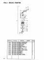
IG.4
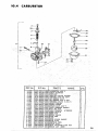
CARBURETOR
f
/""
/-
_38
0--
4o
12
17
30_
21
31_
......
:j%,,,
REENo.
4-000
4-002
4-003
4-004
4-005
4-000
4-007
4-008
4-010
4-011
4-012
4-018
4-017
4-OF!
4-024
4-026
4-027
4-028
4-029
4-030
4-031_
: 4-037
4-038
4 -039
4-040
P.P.No.
455-20217-900
597-20110-200
595-20200-200
594_20202-200
619-20202-200
593-20202-200
592-2002T-920
591-2005T-200
623-21700-200
622-20217-200
561-20202-900
6O7-EOHO_200
599-gOO]T-740
606-20202-200
994-34040-106
605-20202-200
603-20400-200
_2B-20202-EOO
604-20!t0-200
629-20202-2001
02?-20400-200
571-20200-200
802-20420-200i
598-20202-200
5_8-2005T-gSO
_
-
PARTS
•
NAME,
i O'ty
,4
CARBgRETOR ASS'Y
CABLE ADJUSTEE
BODYCAP
TIIEOTTLE VALVE $PR]_Q
TREOTTLE SPEING SEAT
I
.
i
..........
. 1
' _ 1
l
!
,i1
JET HEEOLE
NEEDLE ASS'Y
CLIP
JET
004
THROTTLE VALVE 0.5X1.5
ADJUST SPRIHG
ADJUST SCREV
:
.
OUTLET CLIP ASS'¥
FLOAT CHAHBER GASKET
HAIN JET fT4
FLOAT CHAXBER V/TNREAD
SCREV 4X10/S
CHOKE PIH
NEEDLE VALVE
FLOAT E_
FLOAT
DRAIN SCREV GASKET
DRAIN PLUG
HAN.IFOL_ SEAL
HEEDLE SEAT
CABLE ADJUSTER LOCK NUT
_EEDLH:JET
.2095
'
!
.
1
!
1
l
l
I
2
!
!
1
l
1
l
t
!
1
16
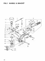
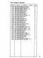
FIG.5
HANDLE
& BRACKET
0
52
47
7
]6 14 15
-54
|_
17
39
22'
23
41
20
4O
31
37
•I•,7
45
HANDLE
REF.No.
_,
& BRACKET,
P.P.No.
J
PARTS
NAME
O'ty
,,
5-000
570-35552-900
5-001
885-01058-800
5-005
200-35300-800
5-006
093-51042-002
5-BB?
999-61600-404
5-008
993-50020-002
5-009
185-35300-203
5-010
OBO-210UO-252
5-01!
992-10060-042
5-012
990-11050-202
5-013
992-10050-042
5-014
18t-35500-202
5-015
793-10200-201
5-016
992-O4080-B31
5-017
100-35552-800i
5-019
102-35500-200
5-020
, 990-21080-302
_5-021'
992-0'1080-041
5-022
991_010E0-021
5_023_ _ 992_1'0080-042;
5-024
134=r35500--201:
_5_025
"]'15--3530_'210
.-,_5-028.1
131-35308-200
5-027"
t35-35500-20I
":-5-028
990-21060-I02
5-029
990-11050-162
5_030,..
992-10050-042
5_031
13T-35500_20!
5_032
138-35500-201
5_033
992-10050-042
5-034
990-11050-122
5':035
139-35500-200
+5-038
t29_35100-200
'_5-037123-35500-201
5_038'_
107_35t18_801
5-039:
106_35119_'80!
5"040
990-2]0U0-752
5-04!
108:35501_:_200
5-042
991-41060-022
5-043 /
992-10060_042
5-044
g92-01060-041
5-045
871-35552-2U0
5-O45
8?2,_35552-290
5-047
873-35552-200
5-048
B74-35552:200
5-049
875-35552-'200
5-050
870-355527200
5-051,
879-35552-209
5-052
99BT11050-202
5-053
991-B1050-02|
5-054
877-355_2-200
5-055
578-35552-200
5-056
903-32201-200
TWIST 6RIP ASS'Y
THROTTLE WIRE COHP.
CLUTCH DRU# COEP.
STOP RtHG C42
BALL BEARING 160040D.
STOP RING C20
CLDTC_ CASE
HEX. BOLT 8X25
$.VASHER B
SCREW 5X20
S.VASHER 5
HAHDLB STOPPER
STEP BOLT
HAVE RASHER 8
5TEERIH6 HAHOLE COHP.
UAHDLE V_SBrE_
_OLT 8X30
WASHER 5
_UT 8
$,VASHER 8
THRUST VASBER
BRACKET
THRUST BRACKET
RETHRH CAH
BOLT BXIO
SCREW 5X10
S,VASHER 5
......
RETUXE CAH GUIDE
RETURK GUIDE PLATE
$.VASEER 5
SCREW 5XI2
.
RETURB SPRIHG
BRACKET PIH STOPPER A
5RAC£ET PIE S
CLAHP-BRACRET B COXP;
CLARP BRACKET A CBXP.
BOLT 6X75
CLAHP BRACKET BgSBIUG
CAP HUT 6
S.VAS'HER U
WASHER 6
!THROTTLE GRIP
ITHROTTLE I_HER .PIPE
THROTTLE HOLBER A
THROTTLE HOLDER H
THROTTLE HOLDER COVER
:WIRE GUIDE
:.
:TAPPIHG_;SCREV '
"
SCREW 5X20
;:
HUT 5
'
:
l
I
1
I
1
I
I
2
2
4
4
I
]
1
1
2
FIG,5
l
1
1
!
l
1
4
I
l
:
l
1
1
4
4
I
I
l
! .
1 .
1 _2
1
1
I
I
l
1
!
1
I
2
2
2
TttROTTLES_OPP'_R::
,t
THROTTLE STOPPERSPRIHG
VIRE CLAKPBA_P
'+
I
I
'
"
18
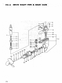
..... FIG.6
DRIVE SHAFT
PiPE'!I_::_GEAR:;¢ASE '_:
/
/
/
,/
/
•
24
T
18
27
28
22
21
23
30
29
19
/
/
PIPE & GEAR
PARTS
P,P.No.
_
!
I
3
2
2
I
2
2
1
!
1
'1
I
1
1
v
v
v
v
l
1
v
v
v
I
i
1
1
!
!
t
l
2
2
1
v,
v
1/
V
t
1
11
!
I
.!
2
?
.
'
L
" .J
,'"
+
+
,
:
.
:'
+
, :: .....
+
....
_
,
,
_
t
'
+
:
%
4
Q'ty
TH]_HST HEAEIH6 '1024
DRIVE SHAFT SHIH 0.50
DRIVE SE_FT S_tE O.tO _ +
DRIVE SHAFT S]flH 0,05 '+
DELVE SHAFT $EIH 0.20
PIHIOH COLLAE ,
P]IilOH
PlRIO]f FIN 4X16
GE/_R COLL_I_
GEAR PIE
DRAIN _ASRET O
BOLT _X8
THRUST VASHER 1024
i
t
;
t .......
NAME
DRIVE SHAFT PiPE A$S*Y
DRIVE SHAFT COHP.
BEARIHG BOLDER CLIP
HEEDLE 5EAHI'H6 10t5
BEAR IiiGHOLDEI_
OKlV_ SHAFT pIPE-GASKET
_OLT 6X18
S,VASHER 6
BOLT 8X40
S.VASBER 8
GEA_ CASE HOLD]_R
DRIVE SHAFT PIPE GASRET
9EAR CASE ASS'¥
BALL *BEA'R'IRG 16900
FLAIH BEAR.I]_G
.
OIL SEAL 10228 ..... :
PROPELLER SHAFT SAlt4 E 0,$0
PROPELLER SHAFT SHIH A 0.20
PKOPI';LLER SHAFT SHIH A 0.30
PROPELLER SHAFT SliIH A 1,0
STOP Ring C-ZO EX
GEAR
_EAA SHAFT Sllll_ 0,10
GEAR SHAFT SHIH 0.20
6EAR SHAET SHIN 0.30
GEAR CASE:,GASKET
BALL BEARING 10001
GEAR CASE COVER
OIL SEAL 12227
PROPELLER SHAFT
SHEA_ FIH
COTTER P l_
P20PELLEE
_BOLT 6X18"
.
8-OOl
090-35306-900
6-002
075-35300-800
9-003
OSB-S5_O0+200
8-004
999-82101-521
6-005
039-35500-200
0-000
091-35500-200
8-007
99o-21000-182
6-008
992-t1090-942
6-009
990-21080-402
6-010
992-10080-042
6-0t!
034-35500-201
6-012
091-35500-200
6-013
031-35500-900
8-014
999-81000-000
8-015
032-35500-210
6-016
999-00402-209
8-017
171-35500-201
6-017
173-35500-200
0-017
174-35500-200
8-017
I75-35500-200
6-018
993-50010-002
8-019
017-36120-201
6-020.
330-00200-2!0
0-020
330-00200-230
8-020
330-00206-24¢
6-021
048-35500-202
8-022
999-61600-100
6-023
046-35506-200
6-024
999-_5122-2BS
6-025
019-35500-201
6-026
012-35500-200
6-02T
011-35100-200
6-028
010-35555-200
8-029
990_21060-182
6-030
992-11060-042
8-031
999;62102_463
8-032
083:35500-200
6-032
064_35500-290
6-032
065-3550,0-200
8-032
066-35500-200
6-033
062-3550.0-200
8-034
080-35300-200
0-035
061-35500-20C
6-035026_35500-200
8-037
025-35500-200
8-038
31T-02000-200
6-039
_96-2_0_0-062
8-040
999-62102-464
+
RERNo: ....
SHAFT
r
DRIVE
I
FIG.6
"
r
. .
i
]
20.:i¸i
¸
TOOLS
FIG.7
o
REENo.
7ooo
PARTS
: P.P.No.
:
:
7-001
7"002
85_-20000-20|
808-20000-200
"
?-003
882-20000-200
SP^HHER lOX13
PLUS DRIVER 4
D48-32352-200'
TOOL
7-004
:
NAME
O'ty
Tool _T ....
gas-3s3o4:goo
sP^_KPLuG
_oxsP^,,E_
[
1
1
1
1
BAG
i
•
i
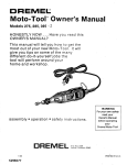
MODEL NO.
298.586190
t owner's
responsibilily
,o m_iintenance
i_
_*_operation
• Irouble
" shooling
• replacemen!
parls
Publication
967-45560-204
No,