1
INSTALLER / CONSUMER
SAFETY INFORMATION
PLEASE READ THIS MANUAL
BEFORE INSTALLING AND USING
APPLIANCE.
WARNING!
IF THE INFORMATION IN THIS
MANUAL IS NOT FOLLOWED
EXACTLY, A FIRE OR EXPLOSION
MAY RESULT CAUSING
PROPERTY DAMAGE, PERSONAL
INJURY OR LOSS OF LIFE.
— Do not store or use gasoline
or other flammable vapors and
liquids in the vicinity of this or
any other appliance.
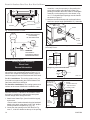
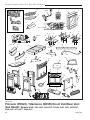
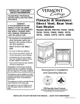
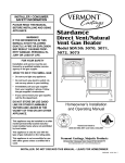
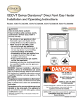
Pinnacle & Stardance
Direct Vent, Rear Vent
Gas Heater
Models:
SDVR: 3920-3936, 3960-3976
PDV20: 2995, 2997, 4065-4067,
4069-4072, 4075-4077, 4080-4083
— WHAT TO DO IF YOU SMELL
GAS:
• Do not try to light any appliance.
• Do not touch any electric switch; do
not use any phone in your building.
• Immediately call your gas supplier
from your neighbor’s phone. Follow
the gas supplier’s instructions.
• If you cannot reach your gas supplier,
call the fire department.
Installation and service must be
performed by a qualified installer,
service agency or the gas
supplier.
This appliance may be installed in an
after market permanently located
manufactured (mobile) home where not
prohibited by local codes.
Homeowner’s Installation
and Operating Manual
DE S I GN
This appliance is only for use with the
type of gas indicated on the rating plate.
This appliance is not convertible for use
with other gases unless a certified kit is
used.
CE
3457
PinStar
cover
10/6/00
C E RT I F I E D
RTIFI E D
INSTALLER: Leave this manual with the appliance.
CONSUMER: Retain this manual for future reference.
20007066 4/07 Rev. 11
Pinnacle & Stardance Direct Vent - Rear Vent Gas Heaters
Table of Contents
PLEASE READ THE INSTALLATION & OPERATING INSTRUCTIONS BEFORE USING APPLIANCE.
Thank you and congratulations on your purchase of a Vermont Castings stove.
IMPORTANT: Read all instructions and warnings carefully before starting installation. Failure to follow these
instructions may result in a possible fire hazard and will void the warranty.
Installation &
Operating
Instructions
Stove Dimensions ................................................................................................................4
Clearance Requirements .....................................................................................................5
Minimum Clearances, Parallel Installation, Corner Installation ............................................5
Minimum Clearances, Alcove Installation .............................................................................6
Mantel Clearances ...............................................................................................................6
Hearth Requirements ...........................................................................................................6
Gas Specifications................................................................................................................6
Gas Inlet and Manifold Pressures ........................................................................................6
High Elevations ....................................................................................................................7
Horizontal Termination..........................................................................................................7
Vertical Termination ..............................................................................................................8
Vent Termination Clearances ...............................................................................................8
General Venting Information - Termination Location ..........................................................10
Termination Clearances ..................................................................................................... 11
Vent Components ...............................................................................................................12
Installation
Install Optional FK28 Fan Kit .............................................................................................13
Venting System Assembly - Direct Vent .............................................................................14
Rear Vent ...........................................................................................................................14
Through Side Wall / Vent Termination Below Grade ..........................................................15
Side Wall Termination Assembly ........................................................................................16
Vent Termination Below Grade ...........................................................................................17
Vertical (Through the Roof) Vent Assembly .......................................................................18
Vertical Through Existing Chimney ....................................................................................19
Fireplace Vent Termination Clearances..............................................................................19
Fireplace Installation Requirements ...................................................................................21
Connect Gas Supply Line ..................................................................................................23
Burner Information..............................................................................................................23
Complete the Assembly .....................................................................................................23
Install ON/OFF Switch (R Models Only) .............................................................................23
Install the Front Plate .........................................................................................................24
Thermostat Connection ......................................................................................................24
Install the Log Set ..............................................................................................................25
Operation
Operable Doors ..................................................................................................................26
Your First Fire .....................................................................................................................26
Pilot and Burner Inspection ................................................................................................26
Flame & Temperature Adjustment ......................................................................................26
Flame Characteristics.........................................................................................................26
Lighting and Operating Instructions ...................................................................................28
Troubleshooting ..................................................................................................................29
Instructions for RF Comfort Control Valve ..........................................................................30
Fuel Conversion Instructions ..............................................................................................33
Maintenance
Annual System Inspection ..................................................................................................37
Logset and Burner Cleaning ..............................................................................................37
Care of Cast Iron ................................................................................................................37
Cleaning the Glass .............................................................................................................37
Glass Replacement ............................................................................................................37
Gasket Replacement ..........................................................................................................38
Inspect the Vent System Annually ......................................................................................38
Check the Gas Flame Regularly ........................................................................................38
Stove Disassembly .............................................................................................................39
Wiring Diagrams .................................................................................................................39
Replacement Parts ..........................................................................................................................................40
Optional Accessories ......................................................................................................................................43
...........................................................................................................................................47
Warranty
Energuide
...........................................................................................................................................48
2
20007066
Pinnacle & Stardance Direct Vent - Rear Vent Gas Heaters
Installation & Operating Instructions
The Pinnacle (PDV20) and Stardance (SDVR) Direct Vent
Room Heater, Model Nos. 3920-3936, 3960-3976, 2995,
2997, 4065-4067, 4069-4072, 4075-4077, 4080-4083 are
vented gas appliances listed to ANSI Standard Z21.882005 and CSA-2.33-2005 for Vented Room Heaters, and
CSA 2.17-M91, Gas-Fired Appliances For Use at High
Altitudes.
The installation of the PDV20 and SDVR Direct Vent Room
Heaters must conform with local codes, or in the absence
of local codes, with National Fuel Gas Code, ANSI Z223.1/
NFPA 54 — latest edition and CSA B-149.1 (EXCEPTION:
Do not derate this appliance for altitude. Maintain the manifold pressure at 3.5” w.c. for Natural Gas and 10” w.c. for LP
gas at maximum input.) Refer to Page 37 (RF only).
This appliance is only for use with the type of gas indicated
on the rating plate. This appliance is not convertible for use
with other gases unless a certified kit is used.
Installation and replacement of gas piping, gas utilization equipment or accessories, and repair and servicing
of equipment shall be performed only by a qualified
agency, preferably NFI or WETT (Canada) certified. The
term “qualified agency” means any individual, firm, corporation, or company that either in person or through
a representative is engaged in and is responsible for
(a) installation or replacement of gas piping, or (b), the
connection, installation, repair, or servicing of equipment, who is experienced in such work, familiar with
all precautions required, and has complied with all the
requirements of the authority having jurisdiction.
The PDV20 and SDVR Direct Vent Room Heaters should
be inspected before use and at least annually by a
qualified service agency. It is imperative that control
compartments, burners, and circulating air passageways of the appliance be kept clean.
The PDV20 and SDVR Direct Vent Room Heaters and the
individual shut-off valve must be disconnected from the gas
supply piping during any pressure testing of that system at
test pressures in excess of 1/2 psig (3.5 kPa).
The PDV20 and SDVR Direct Vent Room Heaters must be
isolated from the gas supply piping system by closing the
individual manual shutoff valve during any pressure testing
of the gas supply piping system at test pressures equal to
or less than 1/2 psig.
An accessible tap is located above the pilot/on-off knob for
checking the inlet pressure.
‘Direct Vent’ describes a sealed combustion system in which
incoming outside air for combustion and outgoing exhaust
enter and exit through two separate concentric passages
within the same sealed vent system. The system does
not use room air to support combustion. The Direct Vent
system permits the gas appliance to be vented directly to
the outside atmosphere through the side of the house or
vertically through the roof.
This appliance is approved for bedroom installations in the
U.S. and Canada.
This appliance may be installed in an aftermarket* manufactured (mobile) home, where not prohibited by state or
local codes.
20007066
WARNING: Operation of this heater when not connected
to a properly installed and maintained venting system
can result in carbon monoxide (CO) poisoning and
possible death.
The PDV20 and SDVR Direct Vent Room Heater, when
installed, must be electrically grounded in accordance
with local codes or, in the absence of local codes, with the
National Electrical Code ANSI/NFPA 70, (latest edition), or
of the current Canadian Electrical Code C22.1.
Due to high temperatures this appliance should be
located out of traffic and away from furniture and
draperies.
WARNING: This appliance is hot while in operation.
Keep children, clothing, and furniture away. Contact may
cause burns or ignition of combustible materials.
Children and adults should be alerted to the hazards
of high surface temperatures and should stay away to
avoid burns or clothing ignition. Young children should
be carefully supervised when they are in the same room
as the appliance.
Clothing or other flammable materials should not be
placed on or near the appliance.
Any safety screen, glass or guard removed for servicing an appliance must be replaced prior to operating
the appliance.
The appliance area must be kept clear and free from
combustible materials, gasoline, and other flammable
vapors and liquids.
The flow of combustion and ventilation air must not
be obstructed. The installation must include adequate
accessibility and clearance for servicing and proper
operation.
WARNING: Do not operate the Room Heater with the
glass panel removed, cracked or broken. Replacement
of the panel should be done by a licensed or qualified
service person.
Do not use this appliance if any part has been under
water. Immediately call a qualified service technician
to inspect the appliance and to replace any part of the
control system and any gas control which has been
under water.
Do not burn wood, trash or any other material for which
this appliance was not designed. This appliance is designed to burn either natural gas or propane only.
This gas appliance must not be connected to a chimney
flue serving a separate solid-fuel burning appliance.
CAUTION: Label all wires prior to disconnection when
servicing controls. Wiring errors can cause improper
and dangerous operation.
Verify proper operation after servicing.
Proposition 65 Warning: Fuels used in gas, woodburning or
oil fired appliances, and the products of combustion of such
fuels, contain chemicals known to the State of California to
cause cancer, birth defects and other reproductive harm.
California Health & Safety Code Sec. 25249.6
* Aftermarket: Completion of sale, nor for purpose of resale,
from the manufacturer.
3
Pinnacle & Stardance Direct Vent - Rear Vent Gas Heaters
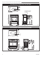
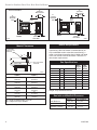
Stove Dimensions - Pinnacle Direct Vent Gas Heater
5"
(140mm)
17"
(432mm)
Flue Transition Connector
(For fireplace installation
only)
24³⁄₈"
(619mm)
25¹⁄₄"
(641mm)
22³⁄₈"
(568mm)
16³⁄₈"
(400mm)
26¹⁄₂"
(673mm)
3457
Fig. 1 PDV20 dimensions.
Stove Dimensions - Stardance Direct Vent Gas Heater
3457
Pinnacle specs
9"
10/9/00
(229
mm)
CL Valve
Inlet
26���"
(680 mm)
26"
(660 mm)
24"
(610 mm)
Valve Inlet
CL
3"
25"
(635 mm)
(76 mm)
14"
(356 mm)
3457
Fig. 2 SDVR dimensions.
4
3457
SDVR
dimensions
10/9/00 djt
20007066
Pinnacle & Stardance Direct Vent - Rear Vent Gas Heaters
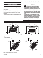
Clearance Requirements
WARNING:
Minimum Clearances to Combustible Materials
Measure side clearances as shown in Figures 3, 4 and
5 from the outer edge of the cast iron stove top. Measure rear clearances from the outermost surface of the
steel rear skirt.
The PDV20 and SDVR heaters are approved for installation into an alcove constructed of combustible materials to the dimensions and clearances shown on the
next page.
The same clearances apply in a standard parallel installation.
• Always maintain required clearances
(air spaces) to nearby combustibles
to prevent fire hazard. Do not fill air spaces
with insulation. All venting components must
maintain a 1” (25mm) clearance to combustible materials. Maintain a 6” (152mm) clearance when using single wall pipe. Maintain a
2” (51mm) clearance on top and 1” (25 mm) on
sides and bottom when venting straight off the
rear.
• The gas appliance and vent system must be
vented directly to the outside of the building
and never be attached to a chimney serving a
separate solid fuel or gas-burning appliance.
• Refer to the manufacturer’s instructions included with the venting system for complete
installation procedures.
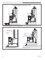
Minimum Clearances
Parallel Installation
C
L
�����"
(476mm)
C
L
18���"
(476mm)
2���"
(64mm)
6"
(150mm)
6"
(150mm)
PDV20
�"
(152 mm)
ST128c
Fig. 3 Parallel installationST128c
minimum clearances and flue centerline.
Corner Installation
7¹⁄₂"
(190mm)
2" (50mm)
2"
(50mm)
PDV20
SDVR
�"
(152 mm)
ST128a
ST128a
SDVR
7¹⁄₂"
flue
centerline
(190mm)
10/9/00 djt
PDV20 flue centerline
10/9/00 djt
Max. Vent
Length
20" (508mm)
2���"
(63mm)
Max. Vent
Length
20" (508mm)
2" (50mm)
2"
(50mm)
SDVR
ST129a
Fig. 4 Corner installation minimum clearances.
20007066
ST129a
PDV20
rear vent
corner specs
ST129a
stardance
corner specs
10/9/00 djt
5
Pinnacle & Stardance Direct Vent - Rear Vent Gas Heaters
9"
(230mm)
Max. Mantel
Width
Alcove Installation
6"
(150mm)
Sidewall/
Trim
See
Fig. 6
6"
(150mm)
Sidewall/
Trim
2���"
(63mm)
Rear Wall
PDV20
ST381
9"
(230mm)
Max. Mantel
Width
See
Fig. 6
2���"
(63mm)
Rear Wall
SDVR
ST381a
Fig. 5 Alcove installation.
ST381a
Hearth Requirements
ST381
Mantel Clearances
SDVR
The PDV20 and SDVR Heaters
must
be installed on
clearance
diagram
rigid flooring. When the heater
is
installed
directly on
10/9/00 djt
any combustible surface other than wood flooring, a
metal or wood panel extending the full width and depth
of the unit must be used as the hearth. There are no
other hearth requirements.
Pinnacle
clearance diagram
6/00
Combustible
Mantel or Trim
Materials
A
B
3" (75mm) Min.
ST382
PDV20 and SDVR
A (Max.)
B (Min.)
9”
10¹⁄₂”
(230 mm)
(270 mm)
7¹⁄₂”
9”
(190ST382
mm)
(230 mm)
6”
7¹⁄₂”
(152Pinnacle
mm)
(190 mm)
4¹⁄₂”
mantel clearances 6”
(114 mm)
(152 mm)
6/13/00
djt
3”
4¹⁄₂”
(76 mm)
(114 mm)
1¹⁄₂”
3”
(38 mm)
(76 mm)
A = Depth of Mantel and/or Top Trim
B = Height from Top of Heater
Fig. 6 Mantel / top trim clearances.
6
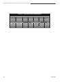
Gas Specifications
Noncombustible
Materials
Model
Fuel
Gas Control
Max.
Input
BTU/h
PDV20RN
PDV20RP
PDV20RFN
PDV20RFP
SDVRRN
SDVRRP
SDVRRFN
SDVRRFP
Nat
Prop
Nat
Prop
Nat
Prop
Nat
Prop
Millivolt
Millivolt
Comfort Control
Comfort Control
Millivolt
Millivolt
Comfort Control
Comfort Control
21,000
21,000
21,000
21,000
21,000
21,000
21,000
21,000
Min.
Input
BTU/h
15,500
16,500
15,500
16,500
15,500
16,500
15,500
16,500
Weight: Fully assembled 350 lbs.
Gas Inlet and Manifold Pressures
Inlet Minimum
Natural
5.5” w.c.
LP (Propane)
11.0” w.c.
Inlet Maximum
14.0” w.c.
14.0” w.c.
Manifold Pressure
3.5” w.c.
10” w.c.
20007066
Pinnacle & Stardance Direct Vent - Rear Vent Gas Heaters
Pinnacle / Stardance
Direct Vent / Rear Vent
Certified to:
ANSI Z21.88-2005 / CSA Z2.33-2005
Vented Gas Fireplace Heaters
The installation must conform with local codes or, in
the absence of local codes, with the National Fuel Gas
Code, ANSI Z223.1/NFPA 54 - latest edition. (EXCEPTION: Do not derate this appliance for altitude. Maintain the manifold pressure at 3.5” w.c. for Natural Gas
and 10” w.c. for Propane.)
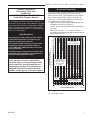
High Elevations
Horizontal Termination
The vent must rise vertically a minimum of 24” (610mm)
after the first elbow directly off the back of the unit,
before the next elbow. The horizontal run may extend
up to 20’ (6m) and include a vertical rise of up to 40’
(12m). (Fig. 7) Horizontal termination must also meet
the criteria shown in Figures 9 and 10.
• Approved vent systems must terminate above and
including the heavy line in Figure 7.
• Two 45° elbows may be substituted for each single
90˚ elbow.
• With a rise between 2’ - 5’, one 90° or two 45° elbows may be used (Excluding the first elbow directly
off the back of the unit.
30
Input ratings are shown in BTU per hour and are
certified without deration for elevations up to
4,500 feet (1,370m) above sea level.
WARNING: Improper installation, adjustment, alteration, service or maintenance
can cause injury or property damage. Refer
to this manual for correct installation and
operational procedures. For assistance or
additional information consult a qualified
installer, service agency, or the gas supplier.
27
Unacceptable
Venting Configuration
26
ST134a
FDV28
Horizonta
vent run
12/3/99 d
areas mo
1/11/00 d
25
Vertical Run (in feet)
In Canada, please consult provincial and/or local
authorities having jurisdiction for installations at
elevations above 4,500 feet (1,370m).
28
Measured after the first elbow. (Transition elbow)
For elevations above 4,500 feet (1,370m) in USA,
installations must be in accordance with the
current ANSI Z223.1/NFPA 54 and/or local codes
having jurisdiction.
29
24
23
22
21
20
19
18
16
May use up to
three 90° Elbows
(Excluding elbow
directly off back
of unit.)
15
14
13
12
11
10
9
8
7
6
5
4
3
One 90°
Elbow*
Unacceptable
Venting Configuration
2
1
0
1 2
3
4
5
6
7
8
9
10 11 12 13 14 15 16 17 18 19 20
Horizontal Run (in feet)
ST134f
Fig. 7 Horizontal vent termination window.
* Not the transition elbow.
20007066
7
Pinnacle & Stardance Direct Vent - Rear Vent Gas Heaters
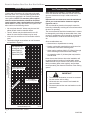
Vertical Termination
A vertical vent system must terminate no less than 8’
(2.44m) and no more than 40’ (12m) above the appliance flue collar. A 2¹⁄₄" restrictor plate (supplied) must
be used (where specified) in all vertically terminated
vent systems. NOTE: The restrictor plate supplied
with the vertical termination should be discarded.
Install restrictor plate supplied with stove directly at
stove outlet. A vertically terminated vent system must
also conform to the following criteria:
• No more than three 90° elbows may be used. 90°
•
•
•
elbow off back must be transition elbow.
Two 45° elbows may be substituted for one 90°
elbow. No more than six elbows may be used.
Vent must rise a minimum of 2 feet before offset is
used.
Termination height must conform to roof clearance
as specified in Figure 9.
38
37
36
35
34
33
• Obstructions or impediments to venting.
• Nearby combustible materials that could come into
All Vertical Terminations in this
area Require
use of the 2¹⁄₄”
Restrictor Plate*
•
•
Vertical Run (in feet)
(Measured after the first elbow. (Transition elbow)
contact with combustion exhaust gases.
Other nearby openings {within 9” (230mm)} through
which exhaust gas could reenter the building.
All vegetation within 3’ (914mm) that may interfere
with the draft.
Other factors that influence where the installation will
be sited include the location of outside walls, where
additional heat may be desired in the home, where the
family members gather most regularly, and perhaps
most importantly, the distance limitations of the venting
system.
31
30
29
28
27
26
24
23
The vent should be placed so that people cannot be
burned by accidentally touching the vent surfaces when
the stove is operating.
Some considerations are:
32
25
When planning the installation, consider the location
of the vent terminal and clearances. Some of the most
common clearances to keep in mind are shown in
Figure 9.
Important: All vent clearances must be maintained.
Check your vent termination clearances against
Figures 9 and 10 .
The vent termination should be located where it cannot
be damaged by such things as automobile doors, lawn
mowers or snowblowers and it should be located away
from areas where it could become blocked by snow,
etc.
40
39
Vent Termination Clearances
Vertical terminations
must be within this area
ST132f
Pinstar
Vertical
vent run
10/9/00 djt
22
21
20
IMPORTANT
19
• The horizontal termination must not be recessed
18
16
15
te
14
to
13
c
tri
12
11
10
o
N
into the exterior wall or siding.
Unacceptable
Venting Configuration
la
rP
• Horizontal vent runs must be level toward the
es
R
•
vent termination.
Clearances around the vent termination must be
maintained.
9
8
7
6
5
4
3
2
1
0
1
2
3
4
5
6
7
8
9
10 11 12 13 14 15 16 17 18 19
Horizontal Run (in feet)
20
ST132f
Fig. 8 Vertical vent termination window.
8
20007066
Pinnacle & Stardance Direct Vent - Rear Vent Gas Heaters
Vent Termination Clearances
Your stove is approved to be vented either through the
side wall, or vertical through the roof.
• CFM Corporation does not require any opening
for inspection of vent pipe.
• Only CFM Corporation venting components
specifically approved and labelled for this stove
may be used.
• Minimum clearances between vent pipes and
combustible materials is one (1”) inch (25mm),
except where stated otherwise.
• Venting terminals shall not be recessed into a wall
or siding.
• Horizontal venting must be installed on a level plane
without an inclining or declining slope.
20007066
There must not be any obstruction such as bushes, garden sheds, fences, decks or utility buildings within 24”
from the front of the termination hood.
Do not locate termination hood where excessive snow
or ice build up may occur. Be sure to check vent termination area after snow falls, and clear to prevent accidental blockage of venting system. When using snow
blowers, make sure snow is not directed towards vent
termination area.
Location of Vent Termination
It is imperative the vent termination be located observing the minimum clearances as shown in Figure 9.
9
Pinnacle & Stardance Direct Vent - Rear Vent Gas Heaters
General Venting Information - Termination Location
INSIDE
CORNER DETAIL
G
V
H
A
N
N
D
L
V
E
C
B
V
F
B
�����
������
Ope
V
Operable
rable
B
B
V
Fixed
Closed
B
V
J
X
X AIR SUPPLY INLET
C = Clearance to permanently closed window
D = Vertical clearance to ventilated soffit located
above the terminal within a horizontal
distance of 2’ (610mm) from the center
line of the terminal
E = Clearance to unventilated soffit
F = Clearance to outside corner
G = Clearance to inside corner (see next page)
H = Clearance to each inside of center line
extended above meter/regulator assembly
V
K
X
AREA WHERE TERMINAL IS NOT PERMITTED
Canadian Installations1
A = Clearance above grade, veranda, porch,
deck, or balcony
B = Clearance to window or door that may be
opened
M
I
A
CFM145a
V VENT TERMINATION
B
V
CFM145a
12”
(30cm)
DV Termin Location
5/01/01 Rev. 12/05/01
sta
6” (15cm) for appliances
< 10,000Btuh (3kW), 12” (30cm)
for appliances > 10,000 Btuh (3kW) and
< 100,000 Btuh (30kW), 36” (91cm)
for appliances > 100,000 Btuh (30kW)
US Installations2
12” (30cm)
12” (305mm) recommended to
prevent window condensation
6” (15cm) for appliances
< 10,000 Btuh (3kW), 9”
(23cm) for appliances > 10,000
Btuh (3kW) and < 50,000 Btuh
(15kW), 12” (30cm) for
appliances > 50,000 Btuh (15kW)
12” (305mm) recommended to
prevent window condensation
18” (458mm)
18” (458mm)
12” (305mm)
see next page
see next page
3’ (91cm) within a height of 15’ (5m)
above the meter/regulator assembly
12” (305mm)
see next page
see next page
3’ (91cm) within a height of 15’
(5m)above the meter/regulator
assy
3’ (91cm)
6” (15cm) for appliances
< 10,000 Btuh (3kW), 9”
(23cm) for appliances > 10,000
Btuh (3kW) and < 50,000 Btuh
(15kW), 12” (30cm) for
appliances > 50,000 Btuh (15kW)
3’ (91cm) above if within 10’
(3m) horizontally
7’ (2.13m)†
I = Clearance to service regulator vent outlet
J = Clearance to nonmechanical air supply inlet
to building or the combustion air inlet to any
other appliances
3’ (91cm)
6” (15cm) for appliances < 10,000
Btuh (3kW), 12” (30cm) for
appliances > 10,000 Btuh (3kW) and <
100,000 Btuh (30kW), 36” (91cm)
for appliances > 100,000 Btuh (30kW)
K = Clearance to a mechanical air supply inlet
6’ (1.83m)
L = Clearance above paved sidewalk or paved 7’ (2.13m)†
driveway located on public property
M = Clearance under veranda, porch, deck or
12” (30cm)‡
12” (30cm)‡
balcony
N = Clearance above a roof shall extend a minimum of 24” (610mm) above the highest point when it passes through the roof
surface, and any other obstruction within a horizontal distance of 18” (450mm).
1 In accordance with the current CSA-B149 Installation Codes
2 In accordance with the current ANSI Z223.1/NFPA 54 National Fuel Gas Codes
† A vent shall not terminate directly above a sidewalk or paved driveway which is located between two single family dwellings and serves both
dwellings
‡ only permitted if veranda, porch, deck or balcony is fully open on a minimum 2 sides beneath the floor:
NOTE: 1. Local codes or regulations may require different clearances.
2. The special venting system used on Direct Vent Stoves are certified as part of the appliance, with clearances tested and approved by the
listing agency.
3. CFM Corporation assumes no responsibility for the improper performance of the appliance when the venting system does not
meet these requirements.
Fig. 9 Vent termination clearances.
10
20007066
Pinnacle & Stardance Direct Vent - Rear Vent Gas Heaters
Termination Clearances
Termination clearances for buildings with combustible and noncombustible exteriors.
Inside Corner
Alcove Applications*
Outside Corner
G=
Combustible
6" (152 mm)
G
F=
Combustible
6" (152 mm)
Noncombustible
2" (51 mm)
V
Noncombustible
2" (51 mm)
V
C
V
E
O
F
Balcony with perpendicular side wall
Balcony with no side wall
D
C
E = Min. 6” (152 mm) for
non-vinyl sidewalls
Min. 12” (305 mm) for
vinyl sidewalls
O = 8’ (2.4 m) Min.
M
M
V
V
P
M=
Combustible &
Noncombustible
12" (305 mm)
Combustible &
Noncombustible
M = 24" (610 mm)
P = 20” (508 mm)
No.
of Caps
1
2
3
4
DMin.
3’ (914 mm)
6’ (1.8 m)
9’ (2.7 m)
12’ (3.7 m)
CMax.
2 x DActual
1 x DActual
2/3 x DActual
1/2 x DActual
DMin. = # of Termination caps x 3
CMax. = (2 / # termination caps) x DActual
584-15
*NOTE: Termination in an alcove space (spaces open only on one side and with an overhang) is permitted with the dimensions
specified for vinyl or non-vinyl siding and soffits. 1. There must be a 3’ (914 mm) minimum between termination caps. 2. All
mechanical air intakes within 10’ (1 m) of a termination cap must be a minimum of 3’ (914 mm) below the termination cap. 3. All
gravity air intakes within 3’ (914 mm) of a termination cap must be a minimum of 1’ (305 mm) below the termination cap.
Fig. 10 Termination clearances.
20007066
11
Pinnacle & Stardance Direct Vent - Rear Vent Gas Heaters
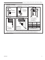
(1) Hardware Package
Vent Components
The following kits are available to meet the needs of most
installations. All pipe has a 7” outer diameter and includes a
4” diameter inner section. A (CG) designation indicates the
part is finished in Charcoal Gray paint. Consult your dealer
about other vent parts that may be appropriate to complete
the installation.
CFM Corporation Vent Components
Rear Vent Kit
7TFSRSK
(1) 20” Starter pipe (CG) for through wall installation
(1) Side Wall Termination
(1) Finishing Collar (CG)
(1) Firestop
(1)Zero Clearance Sleeve
(1) Wall plate (CG)
(1) Hardware Package
Min. Through the Wall Vent Kit
(1) 90-Degree Elbow (CG)
(1) 24” Straight pipe (CG)
(1) 24” - 42” Adjustable Straight Pipe
(1) Side Wall Termination
(1) Firestop
(1) Zero-clearance sleeve
(1) Hardware package
(1) Finishing plate (CG)
(1) Finishing collar (CG)
(4) Charcoal Gray flue pipe rings
Starter Kit for
Below-Grade Installation
(1) Snorkel Termination (7TDVSNORK)
7TFSSK
7TFSDVSKS
Vertical Termination Kit, 1/12-6/12 Pitch
7TDVSKVA
(1) Combination Horizontal Offset / Roof Support
(1) Vertical Termination
(1) Storm Collar
(1) 1/12-6/12 Flashing
(1) Finishing Plate (CG)
(1) Finishing Collar (CG)
(1) Polished Brass Flue Pipe Ring
12
Vertical Termination Kit, 7/12-12/12 Pitch
7TDVSKVB
(1) 7/12 - 12/12 Flashing
and all of the other Vertical Termination parts.
Vertical Termination, Flat Roof
7DVSKVF
(1) Flat Flashing
and all of the other Vertical Termination parts.
Twist Lock 12” Straight Pipe (CG)
(1) 12” Non-adjustable Pipe
7TFSDVP12
Twist Lock 12”-18” Straight Pipe (CG)
7TFSDVP1218
(1) 12” - 18” Adjustable Pipe
Twist Lock 24” Straight Pipe (CG)
(1) 24” Non-adjustable Pipe
7TFSDVP24
Twist Lock 48” Straight Pipe (CG)
(1) 48” Nonadjustable Pipe
7TFSDVP48
Twist Lock 45-Degree Elbow (CG)
for vertical offsets
(1) 45-degree Elbow
7TFSDVT45
Combination Offset/Roof Support
7DVCS
Attic Insulation Shield
7DVAIS
7” Charcoal Gray Pipe Rings, (4)
7FSDRG
7” Polished Brass Pipe Rings (4)
7FSDRP
Use the following approved CFM/Majestic vent components for fireplace installations vented through a
masonry chimney:
7TFSCSK
Transition Connector
HEDV25
25-foot flex connector
(two 25 foot sections)
HEDV35
35-foot flex connector
(two 35 foot sections)
HEDV32T812
Vent termination for 8 x 12” flue
HEDV32T1212
Vent termination for 12 x 12” flue
HEDVT
Round termination
20007066
Pinnacle & Stardance Direct Vent - Rear Vent Gas Heaters
Installation
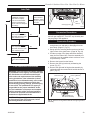
Unpack the Stove
The stove is shipped fully assembled on its back. Unpack the stove and carefully set it upright.
1/4-20 x 3/8”
Hex Head Bolt
CAUTION
Bracket
Porcelain enamelled surfaces are fragile. Handle
porcelain enamelled castings tenderly. Familiarize
yourself with the assembly steps before you begin
and proceed with deliberation and care. If possible,
have assistance available.
Place enamelled castings on a soft, cushioned surface until you are ready to assemble.
Avoid contact between the castings and other hard
surfaces or objects.
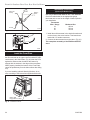
NOTE: Verify the two relief doors (located on top of
the firebox) are properly seated on the gasket. The
doors sit flush on the gasket, and should lift easily
from the seal around the opening.
If you are not installing a fan, proceed to the appropriate vent assembly section.
Snapstat
1/2” Sheet
Metal Screws
FK101a
Fig. 11 Snapstat assembly and installation.
Upper
Flange
FK101
Install snapstat
6/00
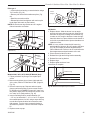
Install Optional Fan Kit #2960/FK28
Fan Kit Contents:
•
•
•
•
•
#10 x 1/2” phillips screws, 6
Control Knob
Retainer Collar
Snapstat
• Snapstat Bracket
Blower Assembly w/ Rheostat Control
ST240
Fig. 12 The upper flange of the fan skirt should be located
behind the lower edge of the shroud.
ST240
FDV attach fan
12/13/99 djt
NOTE: The Rheostat Assembly and the Snapstat Assembly are not used on RF Models.
For RF Models only: Follow Step 3, then run the
spliced female leads to the front of the stove and attach
to PC board of RF valve. Then follow Step 5.
1. Attach the Snapstat to the Bracket using two #10 x
1/2” phillips sheet metal screws as shown in Figure
12.
2. Locate and remove the 1/4-20 x 3/8” hex head bolt
installed in the hole in the right rear ledge of the
firebox. (Fig. 11) Use that bolt to secure the Snapstat
Bracket to the firebox. The mounting hole is slotted
to allow you to adjust the bracket so that its head
makes contact with the firebox surface. (Fig. 11)
3. Attach the Fan to the firebox by engaging the upper flange of the fan skirt under the lower edge of
the Shroud and secure the skirt with the four screws
provided with the kit. (Figs. 12, 13)
20007066
ST241
Fig. 13 Correct position of fan skirt installation.
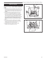
4. The rheostat control switch attaches to the left side of
the valve bracket at the front of the stove. (Fig. 14)
ST240
• Insert the switch
boxfan
shaft through the hole in the
FDV attach
back of the right
side
of
12/13/99 djt the valve bracket, aligning
the locator pin with the smaller hole in that bracket.
• Attach the retaining nut to the switch control shaft
to secure it to the plate.
• Attach the Control Knob to the rheostat shaft.
• Use the wire tie to secure the fan and rheostat
wire harnesses together.
13
Pinnacle & Stardance Direct Vent - Rear Vent Gas Heaters
centerline. It may be necessary to first position the
stove and measure to find the hole location. Depending on whether the wall is made of combustible
materials, cut the opening to the size shown in Figure 17. Combustible wall openings must be framed
as shown in Figure 17.
3. Measure the wall thickness and cut the wall sleeve
sections to proper length (MAXIMUM 12”). Assemble
Retaining Nut
Rheostat Knob
Rheostat
FK104
Sealant
Fig. 14 Attach rheostat to bracket.
Blower Wiring Diagram
FK104
Fan Assembly
Install cover plate
No. 000-2960 / FK28
BLK
BLK
MOTOR
Phillips
Screws
BLK
ST396a
WHT
GRN
WHT
BLK
ON/OFF
RHEOSTAT
SNAPSTAT
WARNING:
DISCONNECT
ELECTRICAL SUPPLY
BEFORE SERVICING
Fig. 15 Blower wiring diagram.
ST236
Venting System
FK26 wiringAssembly
diagram
12/99
Direct Vent
General Information
Fig. 16 Apply sealant to the starter pipe, and fasten to stove
with Phillips screws.
Vent Opening - Combustible
Wall
ST396
9³⁄₈" install start pipe
6/00
(240mm)
10³⁄₈"
(265mm)
Framing Detail
Vent Opening -Noncombustible Wall
The PDV20 and SDVR are approved for installation
only with the vent components listed on Page 13. Follow the vent component instructions exactly. These instructions apply to both the PDV20 and the SDVR shell.
For U.S. installations: The venting system must conform with local codes and/or the current National Fuel
Gas Code, ANSI Z223.1/NFPA 54
For Canadian installations: The venting system must
conform to the current CSA B149.1 installation code.
7¹⁄₂" Dia.
(190mm)
VO584-100
Fig. 17 Locate vent opening.
9³⁄₈” W x 10³⁄₈” H
Wall Opening
Wall Sleeve
- Seal Around
Finishing Collar
Rear Vent
Use Rear Vent Kit 7TFSRSK for an installation where
the heater is parallel to the wall and the vent system
extends straight back through that wall.
1. Attach Inner Starter Pipe, (found in with the logset),
to the stove.
• Run a bead of sealant beneath the pipe bead and
attach to the stove using three 1/4-20 x 3/8” phillips
screws provided in the parts bag. (Fig. 16)
2. Locate the vent opening on the wall. Refer to Figures 17, 18 & 19 to determine the top of the opening
Seal
Around
Terminal
Firestop
Ventilated Wall Plate
- Open End Down
27³⁄₈"
(695mm)
to Top of
Opening
VO584-100
Vent Opening
2/99 djt
ST400
Fig. 18 SDVR with Rear Vent Kit 7TFSRSK installation.
14
20007066
ST477
rear vent kit
6/00
Pinnacle & Stardance Direct Vent - Rear Vent Gas Heaters
9³⁄₈” W x 10³⁄₈” H
Wall Opening
Wall Sleeve
- Seal Around
Firestop
Ventilated Wall Plate
- Open End Down
Finishing Collar
59���"
(1505mm)
Seal
Around
Terminal
25���"
(654mm)
to Top of
Opening
ST400
Fig. 19 PDV20 with Rear Vent Kit 7TFSRSK installation.
4.
5.
6.
7.
the sleeve with the #8 sheet metal screws supplied.
Attach the firestop plate to the sleeve end with the
holes. (Fig. 25) NOTE: The wall sleeve is required in
ST400
combustible walls only.
rear vent kitassembly into the
Install the Wall Firestop/Sleeve
6/00
wall cutout and fasten
the firestop to the wall cutout
framing members. (Figs. 18, 19)
Measure, and cut if necessary, the appropriate
length of pipe section needed to make the connection through the wall.
Slip the wall plate and trim collar over the interior
end of the horizontal pipe and install into the wall
sleeve. Seal the joint inside the wall plate if needed
to keep cold air from being drawn into the home.
Connect the pipe to the inner collar. Fasten the wall
plate to the pipe with three sheet metal screws. Slide
the trim collar up against the wall plate to cover the
screws. (Figs. 18, 19)
8. Install the vent terminal. (Figs. 18, 19) Guide the
inner and outer vent termination collars into the adjacent pipes. Double check that the vent pipes overlap
the collars by 2”. Fasten the termination to the wall
with the screws provided, and caulk the joint with
weatherproof sealant.
Through Side Wall /
Vent Termination Below Grade
Refer to Figures 20 & 21 for minimum centerline of wall
opening.
1. Attach Inner Starter Pipe, (found in with the logset),
to the stove.
• Run a bead of sealant beneath the pipe bead and
attach to the stove using three 1/4-20 x 3/8” phillips
screws provided in the parts bag. (Fig. 22)
2. Dry fit the inner and outer pipe of the first elbow
directly to the starter pipe.
20007066
ST131c
Fig. 20 Minimum wall thimble centerline.
ST131b
wall thimble
12/3/99 djt
61"
(1549mm)
ST131b
Fig. 21 Minimum wall thimble centerline.
3. Dry fit the Inner pipe assembly to the stove for the
ST131b
purpose of determining
the center line of the pipe on
the wall.
wall thimble
• Side Wall Terminations:
Dry fit
12/3/99
djtthe outer elbow
with the vertical outer vent and confirm the centerline
alignment with the wall thimble opening.
4. Attach the elbow to the starter pipe.
• Run a bead of sealant about 1/2” from end of the
starter pipe and attach the assembly to the stove
using three 1/4-20 x 3/8” Phillips screws provided in
the parts bag. (Fig. 22)
15
Pinnacle & Stardance Direct Vent - Rear Vent Gas Heaters
5. Install the first elbow and secure using three sheet
metal screws. Insert the elbow over the stove flue
collar. Also, be sure to align holes on the pipe with
the holes on the flue collar of the firebox. Fasten the
pipe to the holes in the flue collar with the #12 x 1/2”
sheet metal screws provided. (Fig. 23)
Vent Opening - Combustible Wall
9³⁄₈"
(240mm)
9³⁄₈"
(240mm)
Inner Flue Collar
Vent Opening - Noncombustible Wall
Vent Starter Pipe
Inner Elbow
7¹⁄₂"
(191mm)
VO584-100a
Fig. 24 Locate vent opening.
Seal all around
crimped end
ST398b
Fig. 22 Install inner starter pipe and inner elbow.
ST398
install
restrictor plate
& starter pipe inner elbow
6/00
2. Measure the wall thickness and cut the wall sleeve
sections to proper length (MAXIMUM 12”). Assemble
the sleeve with the #8 sheet metal screws supplied.
Attach the firestop plate to the sleeve end with the
holes. (Fig. 25) NOTE: The wall sleeve is required
in combustible walls only.
3. Install the Wall Firestop/Sleeve
VO584-100 assembly into the
wall cutout and fasten
firestop to the wall cutout
Ventthe
Opening
framing members. (Fig. 25)
2/99 djt
12”
(305mm)
Max. Length
Sleeve
#8 Sheet
Metal Screws
ST479a
Fig. 23 Fasten outer pipe with #12 x 1/2” sheet metal screws.
Side Wall Termination
Assembly
ST398
1. Locate the vent opening on theinstall
wall. Refer to Figures 20 & 21, to determine the restrictor
minimumplate
centerline
& starter
pipeposition
inner elbow
of wall opening. It may be necessary
to first
6/00hole location. Dethe stove and measure to find the
pending on whether the wall is made of combustible
materials, cut the opening to the size shown in Figure 24. Combustible wall openings must be framed
as shown in Figure 24.
16
Firestop
ZCS103
Fig. 25 Assemble the wall sleeve and firestop.
4. If necessary, measure to determine the vertical
length (X) of pipe required from the first (transition)
ZCS103
elbow to the wall cutout centerline, including a 2”
Zero Clearance Sleeve
overlap at the joint.
(Fig. 26) Use a hacksaw or tin
& Firestop
snips to trim the12/6/99
pipe asdjtneeded.
5. Install first the inner then the outer straight pipe
section(s), trimmed end down, to the point of the elbow. Drill 3 holes through each joint and fasten with
sheet metal screws.
6. Install the elbow using 3 sheet metal screws at each
joint.
7. Measure, and cut if necessary, the appropriate
length of pipe section needed to make the connection through the wall. Include a 2” overlap; i.e. from
20007066
Pinnacle & Stardance Direct Vent - Rear Vent Gas Heaters
Trim Collar
Wall
Sleeve
X
Wall Plate
ST216
Fig. 28 Install the horizontal pipe and wall plate parts.
Seal Both Terminal Ends
ST478
Fig. 26 Determine the vertical pipe length.
the elbow to the outside wall face, about 2” or the
ST214
distance required if installing
second
90° elbow.
measureavertical
vent
(Fig. 27)
12/6/99 djt
8. Slip the wall plate and trim collar over the interior
end of the horizontal pipe and install into the wall
sleeve. Seal the joint inside the wall plate if needed
to keep cold air from being drawn into the home.
ST216
install pipe thru wall
12/6/99 djt
Caulk Plate Joint with
Weatherproof Sealant
ST217
Fig. 29 Install the vent terminal.
Vent Termination
Below Grade
ST217
install wall terminal
X
ST215
Fig. 27 Measure the horizontal length.
9. Connect the horizontal pipe to the elbow. Fasten the
wall plate to the pipe with three sheet metal screws.
Slide the trim collar up against the wall plate to cover
the screws. (Fig. 28) ST215
measure thru wall
10.Install the vent terminal. (Fig. 29) Guide the inner
12/6/99 djt
and outer vent termination collars into the adjacent
pipes. Double check that the vent pipes overlap the
collars by 2”. Fasten the termination to the wall with
the screws provided, and caulk the joint with weatherproof sealant.
11.Install Charcoal Gray Pipe Rings (#7FSDRG) or Polished Brass Pipe Rings (#7FSDRP) at pipe joints, if
desired.
20007066
Install Snorkel #7TDVSNORK
12/6/99 djt when it is not possible
to meet the required vent termination clearances of 12”
(305mm) above grade level. The snorkel kit will allow
installation depth of down to 7” (178mm) below grade
level. The seven inches is measured from the center of
the horizontal vent pipe as it penetrates the wall. If the
venting system is installed below grade, a window
well must be installed with adequate and proper
drainage. (Fig. 30)
NOTE: Be sure to maintain side wall clearances and
vent run restrictions. Refer to Figures 3 through 9.
1. Establish the vent hole through the wall.
2. Remove soil to a depth of approximately 16”
(400mm) below the base of the snorkel. Install a
window well (not supplied). Refill the hole with 12”
(305mm) of coarse gravel and maintain a clearance
of at least 4” (102mm) below the snorkel. (Fig. 30)
3. Install the vent system as described on Pages 14-17.
4. Be sure to make a watertight joint around the vent
pipe joint at the inside and outside wall joints.
5. Apply high temperature sealant around the inner
and outer snorkel collars. Join the pipes and fasten
the snorkel termination to the wall with the screws
provided.
17
Pinnacle & Stardance Direct Vent - Rear Vent Gas Heaters
6. Level the soil to maintain a 4” clearance below the
snorkel.
If the foundation is recessed, use extension brackets (not supplied) to fasten the lower portion of the
snorkel. Fasten the brackets to the wall first, and
then fasten to the snorkel with self-tapping #8 x 1/2”
sheet metal screws. Extend the vent pipes out as far
as the protruding wall face. (Fig. 31)
Wall Screws
Snorkel
and Anchors
Termination
Cap
Waterproof Seal
Around Pipe
Vertical (Through the Roof)
Vent Assembly
NOTE: All vertically terminated installations must,
where specified, use the 2¹⁄₄” restrictor plate, to
comply with Vertical Termination Window (Fig. 8,
Page 8), included in the hardware bag. The plate must
be installed within the firebox inner flue collar to insure
a proper air/fuel ration is maintained in an appliance
vented through the roof. (Fig. 32)
Inner Flue Collar
Firestop
2¹⁄₄” Restrictor Plate
Vent Starter Pipe
4” Clearance
Gravel
Drain
Window Well
Seal all
around
crimped end
ST398c
Fig. 32 Install restrictor plate and starter pipe/inner elbow
assembly.
ST398
ST218a
installconforms to all other
Make certain the vent system
restrictor plate
requirements for vertical termination
as specified on
& starter pipe inner elbow
Page 9.
Fig. 30 Snorkel kit installation.
Recessed Wall
Sheet Metal
Screws and
Bracket
ST218a
Pinstar
install snorkel
10/11/00 djt
6/00
Firestop
Finishing
Collar
Wall Screws
and Anchors
Waterproof Seal
Around Pipe
7” Pipe
ST219
Wall Plate
Fig. 31 Use extension brackets to mount snorkel against
recessed wall.
ST219
snorkel detail
12/6/99 djt
18
This installation will require you to first determine the
roof pitch and use the appropriate vent components.
Refer to Page 10, Figure 9.
1. Locate the final position of the stove, observing all
clearances for both the vent and the stove.
2. Plumb to the center of the inner (4”) flue collar from
the ceiling above, and mark that location.
3. Cut the opening: (Page 17, Fig. 24)
9³⁄₈” x 9³⁄₈” (240 x 240mm)
4. Plumb any additional opening through the roof or
other construction that may be needed. In all cases,
the opening must provide a minimum of 1” (25mm)
clearance to the vent pipe.
5. Place the stove in its final position.
6. Install firestop(s) #7DVFS and Attic Insulation Shield
#7DVAIS as needed. (Fig. 33) If there is a room
above ceiling level, a firestop must be installed on
both the bottom and top sides of the ceiling joists.
If an attic is above ceiling level, an attic insulation
shield must be installed.
7. Install the appropriate roof support and flashing,
making certain that the upper flange of the flashing
base is below the shingles. (Fig. 34)
20007066
Pinnacle & Stardance Direct Vent - Rear Vent Gas Heaters
8. Install appropriate pipe sections until the vent run
reaches above the flashing. The enlarged ends of
the vent sections always face downward.
9. Install the storm collar and seal around the joints. (Fig.
34)
10. Add additional vent lengths to achieve the proper
overall height.
11. Install termination cap.
#7DVAIS
Attic Insulation
Shield
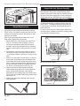
Vertical Through Existing Chimney
The heater must be vented to the outdoors through an
existing masonry or prefabricated fireplace chimney
system through the roof.
The heater is approved to be vented to the outdoors
through any solid-fuel fireplace chimney that has been
constructed or installed in accordance with the national, Provincial/State and local building codes and is
constructed of noncombustible materials. For Venting
Requirements, refer to Page 10. Refer to Venting Components on Page 12.
Fireplace Vent Termination Clearances
Observe the chimney-top vent termination clearances
specified in the instructions provided with those components. Some considerations are:
#7DVFS
Firestop in
Upper Floor
Use Four
8d Nails
• Obstructions or impediments to venting.
• Nearby combustible materials that could come into
•
•
#7DVFS
Firestop in
Ceiling
ST222
Fig. 33 Install firestops and attic insulation shield.
Use three #5
sheet metal ST222
screws at vent thru
each joint
12/99
ceiling
Sealant
Storm
Collar
Upper edge
of flange goes
under upper
shingles
Flashing
#7DVSKV (A,
B, or F) Roof
Support
ST221
Fig. 34 Roof support and flashing.
ST221
vent thru roof
12/99
20007066
contact with combustion exhaust gases.
Other nearby openings (within 9” (230mm) through
which exhaust gas could reenter the building.
All vegetation within 36” (914mm) that may interfere
with the draft.
NOTE: The collar extending down from the Termination base is the air intake collar. Use the flex vent liner,
marked with a blue line, to connect between this collar
and the lower flue collar on the Transition Connector.
Also make sure the other flex vent liner is attached to
the upper Transition Connector collar and the Rain Cap.
(Fig. 35)
1. Clean the top of the chimney as needed, to ensure a
good seal between it and the vent termination.
2. Slide the insulation sleeves provided in the termination kit over the two 3” flex liners (to be attached to
the 3” flue collar and cap of the termination assembly).
3. Feed 3” flex vent from the bottom of the termination
assembly up through the 4” sleeve. Apply high-temperature sealant to the rain cap collar, and slide the
flex vent over the end of the rain cap collar, fastening
with the clamp provided.
4. Slide the flex liner back through the 4” sleeve until
the rain cap/collar engages over the sleeve. Attach
the cap to the sleeve with three sheet metal screws
provided in the kit.
5. Apply high-temperature sealant over the air intake
collar, and attach the intake flex vent (blue) with a
clamp.
6. Apply high-temperature sealant to the top of the
chimney. Feed the two liners down through the
chimney flue and damper opening. Fasten the termination assembly to the chimney with the four set
screws (C) provided.
19
Pinnacle & Stardance Direct Vent - Rear Vent Gas Heaters
7. Trim the flex liners as needed. Each should be only
long enough to connect to the Transition Connector.
There should be no sag in either flex liner when the
stove is in place.
8. Attach the flex liners to the Transition Connector, using high-temperature sealant and clamps as shown
in Figure 35. Prop the connector in rough position
until the heater is in place in front of it.
Fireplace Vent System
B
B
A
B
D
B
C
C
B
A = Sealant Locations
B = Sheet Metal Screws
C = Termination Screws
D = Clamps
A
A
D
C
B
A
B
D
A
A
B
D
ST395
Fig. 35 Fireplace vent system installation.
ST395
Fireplace
vent system
6/00
20
20007066
Pinnacle & Stardance Direct Vent - Rear Vent Gas Heaters
Fireplace Installation Requirements - PDV20
Transition
Connector
25���"
(641mm)
22���"
(568mm)
24���"
(619mm)
Transition
Connector
24���"
(619mm)
15���"
(400mm)
18���"
(476mm)
ST379
ST380
Fig. 36 PDV20 minimum lintel height for flush or forward placement.
Fireplace
Installations Using Existing Wood Stove Chimneys
ST379
ST380
PDV20
min. lintel height
6/00
Pinnacle
Min. fireplace installation
6/00
Existing Wood Stove
Chimney PIpe
Existing Vent
Pipe
Finished Combustible Wall
Field
Fabricated Cover
Transition Connector
*
6"
(152mm)
22³⁄₈"
(568mm)
24³⁄₈"
(619mm)
X
18³⁄₄"
(476mm)
ST715
ST713
* Transition pipe must be at least 6” (152mm)
from any combustible material.
“X” must be 6” (152mm) from any combustible material unless
completely covered by field fabricated sheet metal. If 3” vent
pipes are covered by sheet metal, the clearance to combustibles may be 2” (51mm).
ST715
Fig. 37 PDV20 installations using existing wood stove chimney pipe.
ST713
PDV20
existing stove chimney
3/02
20007066
PDV20
thru fireplace
chimney wall
4/02
21
Pinnacle & Stardance Direct Vent - Rear Vent Gas Heaters
Fireplace Installation Requirements - SDVR
Transition
Connector
Transition
Connector
26"
(660mm)
26"
(660mm)
20���"
(521mm)
16"
(406mm)
ST380a
ST379a
Fig. 38 SDVR minimum lintel height for flush or forward placement.
Fireplace Installations Using Existing Wood Stove Chimneys
ST380a
SDVR
min. lintel height
6/00
ST379a
SDVR
Min. fireplace installation
Existing Wood6/00
Stove
Chimney Pipe
Finished Combustible Wall
Existing Vent Pipe
Field
Fabricated Cover
*6"
(152mm)
Transition Connector
26"
(660mm)
X
20¹⁄₂"
(521mm)
ST714
ST713a
* Transition pipe must be at least 6”
(152mm) from any combustible material.
Fig. 39 SDVR installations using existing wood stove chimney pipe.
ST713a
SDVR
existing stove chimney
3/02
22
“X” must be 6” (151mm) from any combustible material unless
completely covered by field fabricated sheet metal. If 3” vent
pipes are covered by sheet metal, the clearance to combustibles may be 2” (51mm).
ST714
SDVR
thru fireplace
chimney wall
4/02
20007066
Pinnacle & Stardance Direct Vent - Rear Vent Gas Heaters
Connect the Gas Supply Line
Check the rating plate attached by a steel cable to the
firebox, to confirm that you have the appropriate firebox
for the type of fuel to be used. The PDV20 and SDVR
may be converted from one gas to another using the
appropriate Fuel Conversion Kit listed on Page 41.
Burner Information
The appliance must only use the gas specified on the
rating plate, unless converted using a Vermont Castings
Fuel Conversion Kit. Refer to Page 41 for correct Fuel
Conversion Kit for your stove model.
Coversion instructions are provided with each kit and
beginning on Page 33 of this manual.
CAUTION
THIS APPLIANCE SHOULD BE CONNECTED TO
THE GAS SUPPLY ONLY BY A QUALIFIED GAS
SERVICE TECHNICIAN. FOLLOW ALL LOCAL
CODES.
THERE MUST BE A GAS SHUT-OFF BETWEEN
THE STOVE AND THE SUPPLY.
This appliance should only be connected by a qualified gas technician. Test to
confirm manifold pressures as specified
below.
The PDV20 and SDVR Heaters and the individual
shutoff valves must be disconnected from the
gas supply piping during any pressure testing
of that system at test pressures in excess of 1/2
psig (3.5 kPa).
The PDV20 and SDVR Heaters must be isolated
from the gas supply piping system by closing
the individual manual shutoff valve during any
pressure testing of the gas supply piping system
at test pressure equal to or less than 1/2 psig.
There must be a gas shutoff between the stove
and the supply.
In order to connect Natural Gas, use a fitting
with 3/8” NPT nipple on the valve side and 1/2”
natural gas supply line with an input of 21,000
BTUs at a manifold pressure of 3.5” and minimum inlet supply for adjustment of 5.5” w.c.
In order to connect Propane, use a fitting with
3/8” NPT nipple on the valve side and 1/2”
propane gas supply line with an input of 21,000
BTUs at a manifold pressure of 10.0” and minimum inlet supply for adjustment of 11.0” w.c.
In the U.S.: Gas connection should be made in accordance with current National Fuel Gas Code, ANSI
Z223.1/NFPA 54. Since some municipalities have
additional local codes, be sure to consult your local
authority.
In Canada: consult the local authority and CSA-B149.1
installation code.
In order to connect Natural Gas, use a fitting with a
3/8” NPT nipple on the valve side and 1/2” natural gas
supply line with an input of 21,000 BTU’s at a manifold
pressure of 3.5” and minimum inlet supply for adjustment of 5.5” w.c.
In order to connect Propane, use a fitting with 3/8”
NPT nipple on the valve side and 1/2” propane gas
supply line with an input of 21,000 BTUs at a manifold
pressure of 10.0” and minimum inlet supply for adjustment of 11.0” w.c.
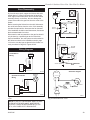
Complete the Assembly
•
Open the swiveling latches (cams) on the top left
and right corners of the glass frame.
• Position the glass and frame against the firebox by
placing the bottom edge on the brackets on the bottom face of the firebox.
• Swing the assembly against the firebox, and close
the latches firmly against the pins protruding from
the firebox top.
Install ON/OFF Switch (R Models ONLY)
The switch assembly parts are found in the parts bag.
1. Attach switch assembly to left rear side of stove
shroud using two screws and existing holes in
shroud. (Fig. 40)
2. Run wires down back of stove, under bottom of rear
shroud to valve.
3. Attach wires to valve terminals. (Fig. 41)
Connect the gas supply and test for leaks. Use a mild
soap and water solution applied with a brush no larger
than 1” (25mm). Never apply soap and water solution
with a spray bottle. Do not use an open flame for leak
testing.
20007066
23
Pinnacle & Stardance Direct Vent - Rear Vent Gas Heaters
Thermostat Connection
Switch Assembly
Existing
Holes
Screws
(Optional) R Models Only
Use only a thermostat rated for 500 - 750 millivolts.
Check the table below for the appropriate gauge
thermostat wire to use for the length of lead required in
your installation.
Thermostat
Wire / Gauge
18
20
22
ST315
Fig. 40 Attach switch assembly to rear shroud.
Maximum Run
40 feet
25 feet
16 feet
PILOT
ADJ
TPTH
TP
TH
1. Install the wall thermostat in the desired location and
run the wires to the stove location. Terminate these
leads with 1/4” female connectors.
2. Connect the thermostat wires to the valve. (Fig. 41)
This completes assembly of the PDV20 and SDVR
stove.
ST228
Fig. 41 Attach switch wires to valve.
Install the Front Plate
ST315
ST228
Grasp the Front Plate and lift it into position, engaging
attach switch
the two steel tabs at the upper corners
behind the
adjaattach
switch
wires to valve
cent bosses in the Side Plates. (Fig. 42) Seat the Front
12/99
against the Sides
so that the tabs at 1/31/00
the bottom lip djt
engage with the notches in the edge of the stove base.
When properly installed, the bottom of the Front Plate
cannot be pulled away from the sides without also lifting
it up.
assy
If you are installing optional Warming Shelves, do so
now, according to the instructions supplied with that kit.
Bottom Tabs
Engage Notch in Base
ST407
Fig. 42 Install Stove Front.
ST407a
install front
12/19/03
24
20007066
Pinnacle & Stardance Direct Vent - Rear Vent Gas Heaters
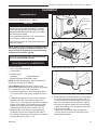
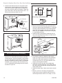
Install the Log Set
Remove the logs from their packaging, and inspect
each piece for damage. DO NOT INSTALL DAMAGED
LOGS.
1. Install the rear log by centering it side to side on the
sheet metal shelf at the back of the firebox. (Fig. 43)
The log will touch both sides and back wall of the
firebox.
2. Install the right log by placing right side of log on
burner so it is just touching firebox side. Lay log
flat on burner almost touching the decorative grate.
Then tilt log back so that it leans against rear log.
(Fig. 43) Only the topmost part of the left side of log
will touch the rear log. The right log sits freely on
the burner and does not use locator pins to stay in
place.
3. Place left log on burner, making sure to engage
locator pins in holes in bottom of the log. (Fig. 43)
This log does not touch any other log.
4. Sprinkle lava rock on burner in front of, and
between, left and right logs. (Fig. 44)
Right Log
Rear Log
LG138
Left Log
Decorative Grate
Fig. 43 Install back, right and left logs.
LG138
Pinstar logs
12/7/00 djt
Lava Rock
Decorative Grate
LG139
Fig. 44 Place lava rock on burner.
LG138
Pinstar logs
12/7/00 djt
20007066
25
Pinnacle & Stardance Direct Vent - Rear Vent Gas Heaters
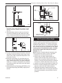
Operation
Piezo Ignitor
Button
OFF
ON P
IL
I
O
T
Pressure Tap
O H
PILOT
ADJ
L
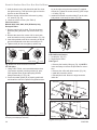
The Stardance is operated with the operable door front
plate in place with the doors open or closed. To open
the front doors, insert the handle into the door latch
stub and turn it to the left and up. (Fig. 45) When not in
use, the handle may be stored in the handle holder on
the right side of the rear shroud. (Fig. 46)
Clockwise to
Open
Regulator
Control Knob
Gas Control Knob
Pilot Adjustment
Screw
HV104
Fig. 47 RN & RP valve control.
HV100
Honeywell Valve
2/11/99 djt
Counterclockwise
to Close
ST621
Fig. 45 To open the front doors, turn handle clockwise.
Handle
Holder
Pilot Assembly
ST624
yourself with the burner controls shown in Figure 47.
Locate the pilot assembly, Figure 48. Follow the lighting
instructions on Page 28 exactly.
During the first fire, it is not unusual to smell some
odor associated with new logs, paint and metal being
heated. Odors should dissipate within a few hours. You
can open a window to provide fresh air to alleviate the
condition.
Pilot and Burner Inspection
ST624
handle holder
2/6/01
Each time you light your heater check that the pilot
flame and burner flame pattern are as shown in Figures
50 through 52. If flame patterns are incorrect, turn the
heater off. Contact your dealer or a qualified gas technician for assistance. Do not operate the heater until the
pilot flame is correct.
Follow regular maintenance procedures as described
on Page 36.
26
ST476a
Fig. 48 Pilot Assembly location.
ST477
Stardance
pilot location
Flame & Temperature
Adjustment
10/4/00
For stoves equipped with
HI/LO valves, flame adjust-
ment is accomplished by rotating the HI/LO adjustment
knob located near the center of the gas control valve.
(Fig. 49)
Turn
counterclockwise
to decrease
flame height
LO
ST261
Stardance
operable doors
Your First Fire
1/31/01
Read these instructions carefully and
familiarize
Fig. 46 When not in use, store handle in the handle holder.
HI
Turn clockwise
to increase
flame height
Fig. 49 Flame adjustment knob for Honeywell valve.
Flame Characteristics
It is important to periodically perform a visual check
of the pilot and the burner flames. Compare them to
HV102
Figures 50 through 52.
Honeywell hi/lo knob
If any of the flames appear
abnormal
call a service
4/5/99
djt
person.
20007066
Pinnacle & Stardance Direct Vent - Rear Vent Gas Heaters
ST233
Fig. 50 Correct pilot flame pattern. PSE Pilot.
Red Glow
LG140a
Fig. 52 Correct burner flame pattern.
LG138
Pinstar logs
12/7/00 djt
CO105c
Fig. 51 Correct pilot flame pattern. SIT pilot.
ST233
pilot
12/9/99 djt
CO105c
Pilot flame
4/10/00 djt
20007066
27
Pinnacle & Stardance Direct Vent - Rear Vent Gas Heaters
Lighting And Operating Instructions
FOR YOUR SAFETY READ BEFORE LIGHTING
WARNING:If you do not follow these instructions exactly, a fire or explosion
may result causing property damage, personal injury or loss of life.
A. This heater has a pilot which must be lit manually.
When lighting the pilot follow these
instructions exactly.
B. BEFORE LIGHTING smell all around the heater
area for gas. Be sure to smell next to the floor
because some gas is heavier than air and will
settle on the floor.
WHAT TO DO IF YOU SMELL GAS
• Do not try to light any fireplace
• Do not touch any electric switch
• Do not use any phone in your building
• Immediately call your gas supplier from a neighbor’s phone. Follow the gas supplier’s instructions.
•
If you cannot reach your gas supplier, call the
Fire Department
C. Use only your hand to push in or turn the gas
control knob. Never use tools. If the knob will not
push in or turn by hand, do not try to repair it, call a
qualified service technician. Applying force or any
attempted repair may result in a fire or explosion.
D. Do not use this fireplace if any part has been under
water. Immediately call a qualified service technician to inspect the heater and to replace any part of
the control system and any gas control which has
been under water.
Lighting Instructions
1. STOP! Read the safety information above.
2. Turn off all electrical power to the fireplace.
3. For MN/MP/TN/TP appliances ONLY, go on to
Step 4. For RN/RP appliances turn the On/Off
switch to “OFF” position or set thermostat to
lowest level.
4. Open control access panel.
5. Push in gas control knob slightly and turn
clockwise
to “OFF”.
T
ON
OFF
LO
3/8" - 1/2"
OFF
OFF
3 4 5
Euro SIT
PI
ON
1 2
P
OFF ilot
PILOT
10. Push the control knob all the way in and hold.
Immediately light the pilot by repeatedly depressing the piezo spark ignitor until a flame appears.
Continue to hold the control knob in for about one
(1) minute after the pilot is lit. Release knob and it
will pop back up. Pilot should remain lit. If it goes
out, repeat steps 5 through 8.
SIT NOVA
Honeywell
6. Wait five (5) minutes to clear out any gas. Then
smell for gas, including near the floor. If you
smell gas, STOP! Follow “B” in the safety inforFP1067
mation above. Iflighting
you do
not smell gas, go to the
instruction
knobs
next step.
3/9/01 djt
7. Remove glass door
before lighting pilot. (See
Glass Frame Removal section).
8. Visibly locate pilot by the main burner.
9. Turn knob on gas control counterclockwise
to “PILOT”.
•
If knob does not pop up when released, stop
and immediately call your service technician or
gas supplier.
FP1068
•
If after several tries,Lighting
the pilotinstructions
will not stay lit,
turn the gas control knobPilots
to “OFF” and call your
service technician or gas supplier.
11. Replace glass door.
12. Turn gas control knob to “ON” position.
13. For RN/RP appliances turn the On/Off switch to
“ON” position or set thermostat to desired setting.
14. Turn on all electrical power to the fireplace.
To Turn Off Gas To Heater
1. Turn the On/Off switch to Off position or set the
thermostat to lowest setting.
2. Turn off all electric power to the fireplace if
service is to be performed.
28
3. Open control access panel.
4. Push in gas control knob slightly and turn clockwise
to “OFF”. Do not force.
5. Close control access panel.
20007066
Pinnacle & Stardance Direct Vent - Rear Vent Gas Heaters
Troubleshooting / Honeywell #8420 Gas Control System
NOTE: Before troubleshooting the gas control system, be sure the external gas shutoff is in the “ON” position.
WARNING: REMOVE THE GLASS PANEL BEFORE PERFORMING ANY GAS CONTROL SERVICE WORK.
SYMPTOM
1. Spark ignitor will
not light
2. Pilot will not stay lit
after carefully following the lighting
instructions
3. Pilot lights, no gas
to burner, valve
knob ON, remote
switch (rocker
switch) ON
POSSIBLE CAUSES
CORRECTIVE ACTION
A. Defective or misaligned
electrode at the pilot
Using a match, light pilot. If pilot lights, turn off pilot and
push the ignitor button again. If pilot will not light, check
gap at electrode and pilot - it should be 1/8” to have a
strong spark.
B. Defective ignitor (push button)
Push piezo ignitor button. Check for spark at electrode
and pilot. If there is no spark at the pilot, and electrode
wire is properly connected, replace ignitor.
A. Defective pilot generator
(thermocouple)
Check pilot flame. It must impinge on the thermocouple
or thermopile. NOTE: This pilot burner assembly uses
both a thermocouple and a thermopile. The thermocouple operates the pilot flame. Tighten the thermocouple.
The thermopile operates the main valve (ON and OFF).
Clean and/or adjust pilot for maximum flame impingement on thermocouple and thermopile.
B. Defective automatic valve
operator
Turn valve knob to ‘Pilot’. Maintain flow to pilot; millivolt
meter should read greater than 10mV. If the reading
is okay and the pilot does not stay on, replace the gas
valve. NOTE: An interrupter block (not supplied) must be
used to conduct this test.
A. Remote switch or wires
defective
Check rocker switch and wires for proper connection.
Use jumper wires across terminals at rocker switch. If
burner lights, replace rocker switch. If okay, use jumper
wires across rocker switch wires at the valve; if burner
lights, wires are faulty or connections are bad.
B. Thermopile may not generate sufficient voltage
1. Be sure wire connections from thermopile at gas valve
terminals are tight and thermopile is fully inserted into
pilot bracket.
2. One of the rocker switch wires may be grounded.
Remove rocker switch wires from valve terminals. If
burner now stays lit, trace rocker switch wiring from
ground. It may be grounded to the appliance or the
gas supply line.
3. Check the thermopile with a millivolt meter. Take reading at thermopile (“TP” and “TP/TH”) terminals of gas
valve. Should read 325 millivolts minimum while holding valve knob depressed in PILOT position and with
rocker switch OFF. Replace faulty thermopile if reading
is below specified minimum.
4. Frequent pilot outage
20007066
C. Plugged burner orifice
Check burner orifices for debris, and remove.
D. Defective automatic valve
operator
Turn knob to ON, place rocker switch to ON, millivolt meter should read greater than 10 mV. If the reading is okay
and the burner does not light, replace the valve.
A. Pilot flame may be too low
or high, (blowing or lifting),
causing the pilot to drop out
B. Possible blockage of the
vent terminal
Clean and/or adjust pilot flame for maximum flame impingement on thermocouple and thermopile.
Check the vent terminal for blockage.
29
Pinnacle & Stardance Direct Vent - Rear Vent Gas Heaters
Instructions for RF Comfort Control Valve
The Comfort Control Valve allows remote control of
temperature, fan and flame appearance.
NOTE: The antenna should hang in free air away from
grounded metal.
Operation
1. If the manual switch is in remote position, switch it to
LOCAL. (Fig. 53)
2. Turn the pilotstat knob counterclockwise from OFF
to the PILOT position, push the knob down, and hold
in position. The pilot valve opens and allows gas to
flow to the pilot burner.
3. Push plunger on the piezo until the pilot burner is lit.
When the pilot burner is lit, the LED on the control
will come on after approximately 40 seconds and
will provide 1 short blink continuously in the normal
mode. When the light turns off which will be approximately 10 seconds after it has been continuously
red, the receiver/valve is fully powered.
Motor Top
Cap
7. If the manual switch is in the LOCAL position, the
valve will be at the highest fixed pressure setting
and the fan will be at the highest fixed speed. The
transmitter will control the fan only.
Shut Off Procedure
If the manual switch is in the REMOTE position, the
transmitter can shut off the main burner and fan. However, the control is still on and a command from the
transmitter can turn on the main burner or fan.
To shut off the system, turn the pilotstat knob clockwise
to the OFF position. This action closes the main gas
and safety valves. The transmitter cannot turn on the
main burner or fan.
Transmitter Operation
Off Mode
In the OFF mode, the fireplace flame and fan are
off, the display will show OFF and displays the room
temperature. If the receiver is in REMOTE mode, the
fireplace will shut off.
Display
Room Temperature
Set Temperature
Flame Height Level
Fan Speed Level
Countdown Timer
Low Battery
Flame
Piezo Ignitor
OFF
•
O
• N
OT
PIL
Mode
Auto
On
Off
LE
D
REMOTE
LOCAL
LED
Local/Remote
Switch
Pilotstat
Knob
FP1037
Fig. 53 Comfort control valve.
4. Release the knob. The shaft will move upward. The
Honeywell
pilot burner should now stay burning. If the pilot
comfort
valve
burner goes out,
repeat
step 2.
3/22/00 djt
5. Turn the knob counterclockwise to the ON position.
If the manual switch is in the LOCAL position, the
main burner will turn on immediately.
6. ON the initial use of a transmitter, a recognition
operation is required between the receiver/valve
and transmitter. Change the switch from LOCAL
to REMOTE. Press the fan or flame button on the
transmitter within 30 seconds. The LED will blink
indicating the transmitter will now work with the receiver/valve. If the switch continues in the REMOTE
position, the transmitter will now control the main
valve, flame modulation level and fan control.
30
Increases Flame
Height, Fan Speed
Timer, or Set Point
Down
Decrease
Flame, Fan
Speed Timer
or Set Point
Fan
Plug
Antenna
FP1037
Up
Countdown
Timer
Fig. 54 Transmitter diagram.
On (Manual) Mode
FP1039
In the ON mode,
the room
comfort
valve temperature, flame and fan
levels will be shown.
MANUAL will appear next to both
transmitter
the flame and 3/27/00
fan icons.
djt
When the control is in the ON mode, the flame and fan
levels, and delay timer are changed with the up and
down buttons. To change the flame level, press the
flame button followed by an arrow key. To change the
fan level, press the fan key followed by an arrow key.
Pushing the arrow key once will change the level by
one unit.
Delay Timer Mode
The shut off delay timer has a maximum of 2 hours and
a minimum of zero minutes. To change the timer level,
press the time key followed by an arrow key. Pushing
the key once will change the timer by 10 minutes.
20007066
Pinnacle & Stardance Direct Vent - Rear Vent Gas Heaters
Auto Mode
Pilot Assembly
In the AUTO mode, the room temperature, set temperature, flame and fan levels will be shown. AUTO will
appear next to both the flame and fan icons.
Fan
When the control is in the AUTO mode, the main burner
will turn on/off or modulate based on the heat needed
to maintain the set temperature. The flame level will
change automatically to optimize the heat output
needed to maintain the set temperature. To change the
set temperature, press the up or down key. Pushing a
key once will change the temperature by one degree.
Red
White
Change Between F/C Temperature Units
Push the up and down arrow keys simultaneously for
at least 3 seconds to toggle between Fahrenheit and
Celsius units.
Disable Thermostat Function
To disable the thermostat function in the AUTO mode,
push the time and down keys simultaneously for at
least 3 seconds.
To Change Batteries
1. Remove cover on the backside of the transmitter.
Install 3 AAA batteries as shown and reattach cover.
2. Once steps 1-3 in OPERATION are completed,
receiver/valve and transmitter are now ready. Press
any button on transmitter for recognition process to
occur between the receiver/valve and transmitter.
3. Use functions as described in TRANSMITTER section.
Troubleshooting
1. Locate LED light on valve.
2. LED will blink after every valid command received by
the transmitter; this is not an error.
3. Failure codes may occur anytime after pilot burner is
lit.
4. Sequence is failure code followed by light not blinking for 30 seconds.
5. In the event of multiple failure codes, next failure
code follows previous failure code by approximately
3 seconds.
20007066
Red
White
White Dots
Antenna
Fan Override During Auto Mode
If a lower or higher fan speed is desired when operating
in the AUTO mode, the fan speed can be overridden by
pushing the fan button followed by the up or down key.
Pushing a key once will change the fan level by one
unit. In this mode “AUTO” is displayed next to the flame
icon and “MANUAL” is displayed next to the fan icon.
FAN
In the AUTO mode, the fan speed will increase with
increasing flame height or decrease with decreasing
flame height. “AUTO” is displayed next to the flame and
fan icons.
Valve
(Bottom View)
FP1038
Fig. 55 Comfort Valve wiring diagram.
FP1038
If an Error Code 3 is observed while performing the
comfort valve
testing, complete the following:
wiring diagram
1. Make sure the spade connectors are pushed all the
3/24/00 djt
way on. If rhe Error Code 3 is still showing, then go
to the next step.
2. Switch the front two thermopile leads with the back
two. Be sure the white lead is connected to the
spade with the white dot next to it. If the Error Code
3 is still showing, replace the thermopiles.
If an Error Code 8 is observed while performing the
testing, complete the following:
1. Confirm the valve is not in REMOTE mode.
• If the valve is producing Error Code 8 and in REMOTE mode, the valve is defective and should be
replaced.
• If the valve is in LOCAL mode and producing Error
Code 8, then go to the next step.
2. Slide the Remote/Local switch to REMOTE and
teach the valve a transmitter (see item 6, page 1).
The Error Code will clear itself after approximately
1.5 minutes and return to normal operation.
LED Count
Service Action
8
Replace valve
7
Confirm stepper motor connection exists
5
Confirm fan connection exists and works
4
Confirm gas type; jumper in place
3
Replace thermopiles
2
Turn fan ON
NOTE: Some keys are not active.
31
Pinnacle & Stardance Direct Vent - Rear Vent Gas Heaters
Comfort Valve System Control Sequence Of Operation With Transmitter
Set manual switch
to local or remote
five minute wait
period
Light pilot burner
Did the LED stop
blinking?
Review LED
failure analysis
Release pilotstat
knob
Yes
Turn pilotstat knob
from PILOT to ON
Cycle switch once
and leave in remote.
Pressy any key on
transmitter for
recognition operation
On Path
Local Path
If manual switch is
set to LOCAL, did
main burner light and
fan turn on?
Yes
Turn pilotstat knob
to PILOT to turn off
main burner.
Turn pilotstat knob
to OFF to turn valve
completely off.
Choose Manual or
Remote path. Set
switch to manual or
remote.
Move switch from
local to remote.
Press any key on
transmitter. Move
switch back to
local.
If the manual switch
is set to REMOTE,
press the mode button to display “ON”.
Does transmitter control the main burner
and fan?
Move switch from
manual to remote.
Press any key on
transmitter.
Yes
Does transmitter
change levels of flame
height, fan speed?
No
Set levels of flame
height and fan to “0:
to shut off main burner
and fan.
Turn pilotstat knob
to OFF to turn valve
completely off.
32
20007066
Pinnacle & Stardance Direct Vent - Rear Vent Gas Heaters
Auto Path
OFF
O H
PILOT
ADJ
ON
I
PIL
OT
Move switch
from LOCAL to
REMOTE. Press
any key within 30
seconds.
L
If the manual switch is set
to REMOTE, press the
mode button to display
AUTO on the transmitter.
Does the transmitter display the room and temperature setting?
Main
Gas Line
Gas Supply Inlet
ST226
Fig. 56 Attach the gas line to the right side of the valve.
If the setting is above
room temperature on the
transmitter, does the main
valve and fan turn on?
Conversion Precautions
No
ST226
Before proceeding, turn
control knob on valve to OFF
attach gas line
and turn gas supply OFF. Turn OFF any electricity that
12/8/99 djt
may be going to the appliance.
Conversion Procedure
If the settings is below
room temperature on the
transmitter, does the main
valve and fan turn off?
No
Turn pilotstat knob to OFF
to turn valve completely
off.
Fuel Conversion Instructions
WARNING! This conversion kit shall be installed
by a qualified service agency in accordance with
the manufacturer’s instructions and all applicable codes and requirements of the authority
having jurisdiction. If the information in these
instructions is not followed exactly, a fire, explosion or production of carbon monoxide may
result causing property damage, personal injury
or loss of life. The qualified service agency is
responsible for the proper installation of this
kit. The installation is not proper and complete
until the operation of the converted appliance
is checked as specified in the manufacturer’s
instructions supplied with the kit.
CAUTION: The gas supply shall be shut off prior
to disconnecting the electrical power, before
proceeding with the conversion.
20007066
1. Remove stove front. Lift stove front up and then
swing bottom out and away to disengage from the
stove body. (Page 37, Fig. 67)
2. Swing open the swiveling latches at the top left and
right corners of the glass frame. (Page 38, Fig. 68)
3. Pull the top edge of the glass and frame assembly
away from the firebox face. Place the assembly out
of the way on a flat, padded surface such as a counter protected by a towel.
4. Remove the logset from the firebox.
5. Remove the rear log bracket by unfastening the
screw. (Fig. 57)
6. Remove the right and left log bracket assembly by
unfastening the two screws which hold the burner in
place. (Fig. 57)
Remove Screws
Rear Log Bracket
Pilot
Left & Right Log
Bracket Assembly
ST350
Fig. 57 Remove rear log bracket and left and right log bracket
assembly.
ST350
Jefferson
air shutter adj
3/20/00 djt
33
Pinnacle & Stardance Direct Vent - Rear Vent Gas Heaters
bly to the valve using the new screws (E) supplied
with the kit. Tighten the screws securely. (Ref. torque
= 25 in/lb) (Fig. 60)
3. Install the enclosed conversion label (F) to the valve
body where it can easily be seen. (Fig. 60)
E
OF
OT
O
D
F
Cap
HI
IL
FP
7. Hold the burner at the right hand side and lift to clear
the right burner leg. Then pull to the right to clear the
injectors on the left hand side.
8. Remove injector orifices from left burner leg using
1/2” wrench. (Fig. 66)
9. Install conversion orifices. (See Table 2)
Valve Conversion
Models 3920, 3930, 4065, 4070 (R Models) Only
Honeywell Valve
1. Remove cap from Hi-Lo knob. This can be accomplished by lifting the plastic cap off the screw. (Fig.
58)
2. Remove the screw from center of Hi-Lo knob with
small screwdriver turning counterclockwise. (Fig. 58)
3. Insert blue painted screw when converting to natural
gas and red painted screw when converting to LP.
4. Tighten screw (do not over tighten), replace cap.
Lift Open
FC108
HI
Fig. 60 Replace regulator.
LO
LO
Hi-Lo
Knob
Center Screw
CO100
Pilot Orifice Conversion
FC108
SIT57)
1. Locate pilot. (Fig.
regulator
2. Replace pilot orifice:
conversion
Pilot Type 1
10/03
• Remove pilot hood by lifting up. (Fig. 61) NOTE: It
Fig. 58 Remove center screw
from Hi-Lo knob.
CO100
Gas conversion
HI-LO knob
SIT 820 Valve
3/15/99 djt
1. Using TORX T20 bit, remove and discard the three
(3) pressure regulator mounting screws (A), pressure regulator tower (B) and the spring and diaphragm assembly (C). (Fig. 59)
2. Insure the rubber gasket (D) is properly positioned
and install the new HI/LO pressure regulator assem-
is not necessary to remove the pilot tube for conversion.
• Remove pilot orifice with allen wrench. (Fig. 62)
• Install the conversion orifice.
• Reinstall pilot hood. Be sure to align hood with
index tab.
Pilot Hood
A
B
Pilot
Bracket
C
CO105a
Fig. 61 Remove pilot hood.
Index Tab
FP
OF
IL
Allen Wrench
OT
O
FC107
Fig. 59 Remove mounting screws, pressure regulator tower
and spring and diaphragm assembly.
Snap Ring
CO105a
gas conversion
Pilot
1/28/00 djt
CO106a
Fig. 62 Remove pilot orifice.
34
FC107
SIT820
valve conversion
10/03
20007066
Pinnacle & Stardance Direct Vent - Rear Vent Gas Heaters
Pilot type 2
Pilot Hood
Index
Marks
Pilot Bracket
CO105
Fig. 63 Remove pilot hood. (Your pilot may have a different
appearance.)
Pilot
CO105
Orifice
Gas Conversion
Pilot
2/15/99 djt
Center
Plunger
OT
PIL
Red - LP
L
Blue - NG
FP1037b
Fig. 65 Depress and turn center plunger.
All Models
1. Replace burner. Slide the burner in at an angle
with left side lower than the right side. Slide the left
side onto the injectors, making sure the burner leg
remains at a 90° angle to the base. Lower the right
hand side down in to place. Make sure the burner is
FP1037b
as far left as possible and the injector shoulders are
comfort valve
inside the burner.
convert
NOTE: It is very critical to keep the left3/6/01
burner djt
leg,
which holds the injectors, at a 90° angle to the base.
(Fig. 66) This keeps the orifices aligned with the
tubes inside burner. Failure to do so could affect the
flame appearance and performance of the unit.
2. Place conversion label on valve.
3. Reinstall the right and left log bracket assembly.
4. Reinstall the rear log bracket.
5. Replace logs.
6. Replace glass and stove front.
Conversion is complete.
CO106b
Fig. 64 Remove pilot orifice.
Models 3960, 3970, 4075, 4080 (RF Models) Only
1. Follow procedure for pilotCO106a
type 2 to replace pilot
orifice.
Gas Conversion
2. Remove and replace plugPilot
on lower
right hand side
(Vermont)
of the valve; Red for LP and
Blue
for
7/19/99 djt NG. (Page 30,
Fig. 53)
3. Remove motor top cap. Depress and turn center
plunger until arrow points to correct screw. Red for
LP and Blue for NG. NOTE: Plunger will “snap” into
NG position when arrow is close to blue screw. It will
not “snap” at LP (Red) position. (Fig. 65)
4. Insure manifold pressure remains between 3.2”
- 3.5” w.c. for NG and 9.5” - 10” w.c. for LP. To adjust
the manifold pressure, for NG, using a torque #10 key
turn the blue screw clockwise to increase the manifold pressure. Turn the screw counterclockwise to
decrease the pressure. Use the red screw to adjust
LP.
5. Replace motor top cap.
20007066
OFF
•
O
• N
Valve
REMOTE
7/16” wrench. (Fig. 63)
• Remove pilot orifice with needlenose pliers. (Fig.
64)
• Install the conversion orifice.
• Reinstall pilot hood and tighten until mark on pilot
hood aligns with mark on pilot bracket.
NOTE: Be sure burner leg remains at a 90° angle to
firebox base after conversion.
Motor Top Cap
LOCAL
• Loosen pilot hood turning counterclockwise using a
Left Burner Leg
Injector Orifices
90°
ST353a
Fig. 66 Remove and replace injector orifices.
ST353a
injector orifice
replace
3/21/00 djt
35
Pinnacle & Stardance Direct Vent - Rear Vent Gas Heaters
Table 2. Injector Orifice Size Matrix
36
Conversion to Natural Gas
Part #
Rear
Part #
Kit #
Front
000-5004
000-5013
#56 / .0465”
#56 / .0465”
Kit #
Front
000-5005
000-5014
#68 / .031”
#68 / .031”
30000336
30000336
#47 / .078”
#47 / .078”
Conversion to LP
Part #
Rear
30000694
30000694
#56 / .0465”
#56 / .0465”
20003054
20003054
Part #
30000336
30000336
Input (BTU/h)
Minimum Maxi,mum
14,000
14,000
21,000
21,000
Input (BTU/h)
Minimum Maximum
14,000
14,000
21,000
21,000
20007066
Pinnacle & Stardance Direct Vent - Rear Vent Gas Heaters
Maintenance
Your PDV20 and SDVR Gas Heaters will provide years
of service with minimal upkeep. The following procedures will help ensure that your stove continues to
function properly.
Annual System Inspection
Have the entire heater and venting system inspected
annually by a qualified gas technician. Replace any
worn or broken parts.
Logset and Burner
Cleaning and Inspection
Cleanliness is critical to the proper function of the
heater. The logset and burner must all be kept free of
dust and unobstructed by debris. Inspect these areas
before each use and clean as necessary.
1. Turn the burner OFF and let the heater cool completely before cleaning.
2. Lift the Stove Front up and then swing the bottom
out to disengage it from the heater shell. (Fig. 67)
3. Carefully remove the glass and frame assembly
and place it out of the way on a flat, padded surface
such as a counter protected by a towel.
4. Carefully inspect the Logs for damage. Contact
your local dealer if any damage is evident. DO NOT
OPERATE THE HEATER WITH DAMAGED LOGS.
5. Use a soft bristled brush to sweep dust or debris
from the Logs, Pilot and Burner. Use care as the
logs are fragile and susceptible to damage.
6. Replace the glass panel and frame assembly.
CAUTION
TURN THE PILOT OFF BEFORE PAINTING.
ALLOW THE HEATER TO COOL COMPLETELY
BEFORE PAINTING.
Cleaning the Glass
WARNING: Let the glass cool completely before attempting to clean.
It will be necessary to clean the glass periodically. During start-up, condensation, which is normal, forms on
the inside of the glass and causes lint, dust and other
airborne particles to cling to the glass surface. Also
initial paint curing may deposit a slight film on the glass.
It is therefore recommended that the glass be cleaned
two or three times with a non-ammonia household
cleaner and warm water (we recommend gas fireplace
glass cleaner). After that the glass should be cleaned
two or three times during each heating season depending on the circumstances present.
Clean glass after first two weeks of operation.
Glass Replacement
Replace glass only with CFM Corporation approved
parts. Refer to Page 40 for Replacement Parts. Refer to
Figure 68 and previous instructions for removal of the
damaged glass frame.
7. Replace the Stove Front.
Care of Cast Iron
An occasional dusting with a dry rag will help keep the
painted surfaces looking new. Use high-temperature
stove paints, available through your local dealer, to
touch-up areas as needed. Clean areas to be painted
with a wire brush and be sure to cover the logs, burner
and valve assembly, glass and frame assembly. Apply
the paint sparingly; two light coats of paint will give better results than a single heavy coat.
Clean porcelain enamel surfaces with a soft, damp
cloth. Do not use abrasive cleaning agents. If necessary, use only a cleaning agent formulated especially
for use on porcelain enamel surfaces.
20007066
ST474d
Fig. 67 Remove the Stove Front.
ST474c
Stardance
Rear vent
Remove Front
10/12/00
37
Pinnacle & Stardance Direct Vent - Rear Vent Gas Heaters
Inspect the Vent System Annually
NOTE: Shown
without top for
clarity.
Have the vent system inspected annually by a qualified technician. Shut off the main gas supply before
inspecting the system. Both the inner exhaust pipe and
the outer combustion supply pipe must be checked to
confirm that they are unblocked and in good condition.
Check the Gas Flame Regularly
ST391a
Fig. 68 Release the latches to release the glass frame.
Gasket Replacement
The PDV20 and SDVR Gas Heaters use a ‘tadpole’
type gasket to seal between the glass panel and the
frame. In time, this gasket can become brittle and compressed and should be replaced. New gasket is available from your dealer.
To ensure that the stove is operating properly, check
the flames periodically to confirm that they match Figures 70 & 71. The flames will be blue during the first
15-20 minutes of operation, and will gradually turn to
yellow after that.
Do not use your stove if the flame pattern differs from
that shown here. Contact your Vermont Castings dealer
or a qualified technician for help.
Shut off the gas supply and allow the stove to cool.
Wear safety goggles and a dust mask.
1. Remove the Front, Glass Frame and Glass Panel.
(Figs. 67, 68) Remove the old gasket. Use a razor blade to separate the glass and gasket from
the frame, and to clean the glass of any remaining
cement or bits of gasket. Use a cold chisel if necessary.
2. Determine the correct length of gasket by laying it
ST391a
out around the edge
of the glass. Allow an extra 1
- 2” (25-50mm). Mark
the spot to be cut. Use a utility
Pinnacle
knife.
release
3. Starting on a long edge,
removelatches
about 6” of the protective paper strip and
apply
the
flat
adhesive face
6/00
of the gasket around the outside-facing edge of the
panel. Continue around the panel, applying about 6”
at a time and being careful to not stretch the material. Do not overlap the gasket ends. (Fig. 69)
4. Apply a thin bead of high temperature silicone
rubber sealant along the inside corner of the glass
frame, all around the perimeter. Place the flat
gasketed side of the glass panel back into the steel
frame. Pinch the rounded inside-facing gasket material to bulk it up.
5. Replace the glass frame and front panel as previously described.
Red Glow
LG140
Fig. 70 Correct flame pattern.
LG138
Pinstar logs
12/7/00 djt
Red Glow
LG155
Fig. 71 Correct flame pattern, Models 2950, 2951.
ST179
Fig. 69 Wrap the gasket material around the outside edge of
the glass.
38
ST179
glass gasket detail
11/99
LG155
PDV 20
log placement
4/16/01
20007066
Pinnacle & Stardance Direct Vent - Rear Vent Gas Heaters
Stove Disassembly
If there is ever a need to remove the firebox assembly from the stove shell, support the firebox with solid
stands about 6” (152mm) tall under the left and right
outer edges of the firebox base. Do not set the firebox
assembly directly on the floor; this can damage the
control valve and/or the gas lines from the valve to the
firebox.
Before removing the firebox from the shell, disconnect
the on/off switch wires from the valve. If the assembly
includes the optional fan, disconnect the fan rheostat.
If the installation includes a wall thermostat, disconnect
the thermostat leads from valve.
FAN
POWER
CORD
BL
Chassis
Ground
K
GRN
BL
Disconnection and reconnection to the gas line should
only be done by a qualified gas service technician.
K
BLK
FAN JUNCTION BOX
Upon reinstallation, the vent system must be sealed to
the firebox as shown in the installation section, page
14. Also be sure the logs are placed in the firebox correctly, as shown in Page 25, Figures 43-44.
Strain Relief
ON / OFF
Rheostat
Wiring Diagrams
OFF
ON
Snapstat
WHT
LK
On/Off Switch
Wiring
B
BLK
GRN
Thermopile
Black
TP/TH
Chassis Ground
RHEOSTAT / SNAPSTAT
BOX
ST153
Millivolt
Gas Valve
TP
Black
TH
Schematic Diagram
ST124b
MOTOR
Thermostat
(Optional)
ST153
rdv connections diag.
BLK
10/99
WHT
GRN
WHT
BLK
TP
TH
BLK
St124b
on/off/switch
wiring
1/11/00 djt
Thermopile
Black
BLK
Thermostat
(Optional)
Optional Thermostat
Wiring
TP/TH
BLK
WHT
SNAPSTAT
ON/OFF
RHEOSTAT
Black
ST124c
Fig. 72 PDV20/SDVR on/off switch and optional thermostat
circuit.
NOTE: IF ANY OF THE ORIGINAL WIRE, AS SUPPLIED WITH THE APPLIANCE, MUST BE REPLACED, IT MUSTSt124c
BE REPLACED WITH TYPE
SF-2, 200°C WIREThermostat
OR ITS EQUIVALENT.
20007066
wiring
1/11/00 djt
ST234
Fig. 73 PDV20/SDVR fan circuit.
ST236
FK26 wiring diagram
12/99
39
Pinnacle & Stardance Direct Vent - Rear Vent Gas Heaters
2
1a
6
5a,b
7
8
3
9
1b
I
PILOT
ADJ
10a,b
13
20a-d
OT
14
12a
15
19
12b
16
12c
OFF
•
11a,b
LE
D
LOCAL
REMOTE
ON
•
PIL
ON
CE
1c
T OFF
LO
PI
L
NT
ME
O H
4
24
17
21
22
18
25
30
41
23
27
26
28
31
29
35
42
32
44
36
37
33
43
34
38
40
39
45
46
48a,b
49
CFM Corporation reserves the right to make changes in design, materials, specifications, prices and discontinue colors and products at any time,
without notice.
7066
PinnStar
fully assembled parts
11/19/03 djt
Pinnacle (PDV20) / Stardance (SDVR) Direct Vent/Rear Vent
Gas Heater: Models SDVR: 3920-3936, 3960-3976; PDV20: 2995, 2997, 4065-4067,
4069-4072, 4075-4077, 4080-4083
40
20007066
Pinnacle & Stardance Direct Vent - Rear Vent Gas Heaters
Pinnacle (PDV20) / Stardance (SDVR) Direct Vent/Rear Vent Gas Heater,
(continued)
Ref. Description
1.
1a.
1b.
1c.
2.
3.
4.
5.
6.
7.
8.
9.
10a.
10b.
11a.
11b.
12a.
PDV20
SDVR
Gas Log Assembly
Log, Rear
Log, Right
Left Log
Grille, UV30
Mesh, Grille - UV30
Cement, Gasket 3oz. Tube
Manifold Assembly
Lava Rocks Burner
Gasket, Glass - Med. Knit-RDV40
Glass, DV25
Glass Frame Assembly, SDV30
Gas Valve, NG - Honeywell VS8420E 2038 (Serial #’s up to 3870)* 10001782
Gas Valve, LP - Honeywell VS8420E 2020 (Serial #’s up to 3870)** 10001759
Valve Gas Honeywell Convertible RFN RV8310E
Valve Gas Honeywell Convertible RFP RV8310E
Pilot Assembly 3Way N/DV RN 0.199.706
Pilot Assembly 3Way N/DV RP 0.199.703
12b. Pilot, PSE - NA175
Pilot, PSE - LP175
12c. Pilot Assembly 3Way DV/RFN CS3003A2009
Pilot Assembly 3Way DV/RFP CS3003A2017
13. Thermocouple, 24”
14. Electrode Ignitor w/ Cable SIT24
15. Pilot Top Convertible
16. Thermopile, 18” RS
17.
18.
19.
20a.
20b.
20c.
20d.
21.
22.
23.
24.
25.
26.
27.
28.
29.
30.
31.
32.
33.
34
35.
36.
Nut Electrode, SIT #0.974.144
Tubing Pilot w/ Fittings 1/8 x 24”
Thermopile - PSE for RF Pilots
Orifice Hood - Front - LP
Orifice Hood - Front - NG
Orifice Hood - Rear - LP
Orifice Hood - Rear - NG
Burner Housing Assembly
Grate, Burner JDV
Wire w/Straight Terms End 50”
Trim ON/OFF Switch - JDV
Control FS/HM
Bracket, Right Log
Bracket, Left Log
Gasket Base Pan
Gasket Inner Base Pan
Top, Stardance UV/PDV
Front, HM-VC
Door, Left - Stardance
Door, Right - Stardance
Front, Stardance OP Door
Nut, Hex Jam 3/8 - 16 TOPLK-Z
Pawl Assy, Ashdoor - ENC
20007066
20003467
20003467
20003463
20003463
20003464
20003464
20003465
20003465
30000393
30000393
30000508
30000508
1206122
1206122
20003739
20003739
57897
57897
1203702
1203702
1601691
1601691
30000127
30000127
10001782
10001759
20003719
20003719
20003720
20003720
10002264
10002264
10002265
10002265
20001115
20001115
20001116
20001116
20002266
20002266
20002268
20002268
53373
53373
7531137
7531137
10001297
10001297
10002266
10002266
51827
51827
7533113
7533113
57886
57886
10001296
10001296
20002400
20002400
30000694
30000694
30000336
30000336
30000336
30000336
20003054
20003054
20004066
20004066
20002167
20002167
10002582
10002582
53606
53606
Refer to Enamel Parts Chart Page 42
20005259
20005259
20002165
20002165
20002282
20002282
20002566
20002566
Refer to Enamel Parts Chart Page 42
Refer to Enamel Parts Chart Page 42
Refer to Enamel Parts Chart Page 42
Refer to Enamel Parts Chart Page 42
Refer to Enamel Parts Chart Page 42
1203290
1203290
5004025
5004025
41
Pinnacle & Stardance Direct Vent - Rear Vent Gas Heaters
Pinnacle (PDV20) / Stardance (SDVR) Direct Vent/Rear Vent Gas Heater
(continued)
Ref. Description
37.
38.
39.
40.
41.
42.
43.
44.
45.
46.
47.
48a.
48b.
49.
50.
PDV20
Front Handle Shaft - NI/VER
Handle Package, Ceramic w/Screw
Rear Shroud Assembly, PDV20
Gasket, HE Door
Left End, PDV20
Right End, PDV20
Left End, SDVR
Right End, SDVR
Transmitter Honeywell RF
FK28 Fan Subassembly for PDVRF
1/4” Fiberglass Gasket
Valve Nova SIT820.662 RN (Serial #’s starting with 3871)
Valve Nova SIT820.653 RP (Serial #’s starting with 3871)
Ignitor Piezo w/Nut SIT
Bracket Piezo Ignitor (not shown)
SDVR
30002717
30002717
0004345
0004345
20003801
20003801
1203687
1203687
Refer to Enamel Parts Chart Page 42
Refer to Enamel Parts Chart Page 42
Refer to Enamel Parts Chart Page 42
Refer to Enamel Parts Chart Page 42
20002047
20002047
30000887
30000887
1203560
1203560
20010563
20010645
52464
20010876
*When converting to SIT valve, must order RP275
**When converting to SIT valve, must order RP269
Fuel Conversion Kits
Conversion Kit, NG to LP
Kit #000-5005
PDV20RFN (Models 2997, 4065-4069, 4075- 4077, 4083) and SDV30RFN (Models 3960 thru 3969)
Conversion Kit, NG to LP
Kit #000-5014
PDV20RN (Models 2995, 4065-4067, 4069) and SDV30RN (Models 3920 thru 3929)
Conversion Kit, LP to NG
Kit #000-5004
PDV20RFP (Models 2998, 4080, 4081, 4082) and SDV30RFP Models 3970 thru 3976)
Conversion Kit, LP to NG
Kit #000-5013
PDV20RP (Models 2996, 4070, 4071, 4072) and SDV30RP Models 3930 thru 3936)
Shell Enamel Part Numbers - PDV20
Color
Top
Left End
Classic
30001278
30001282
Sand
30001299
30001303
Ebony
30001306
30001310
Biscuit
30003307
30003325
Shell Enamel Part Numbers - SDVR
Color
Top
Left End
Classic
30001278
30001280
Biscuit
30003307
30003300
Bordeaux
30001285
30001287
Chestnut Brown 30003315
30003308
Ebony
30001306
30001308
Forest Green
30001292
30001294
Midnight Blue
30001319
30001321
Sand
30001299
30001301
Suede Brown
30002554
30002547
Vermont
Classic Green
30003323
30003316
42
Right End
30001281
30001302
30001309
30003324
Front
1301129
1321129
1341129
30003326
Control Door
1301087
1321087
1341087
30003327
Right End
30001279
30003301
30001286
30003309
30001307
30001293
30001320
30001300
30002548
Front (OP)
30001496
30003302
30001261
30003310
30001270
30001264
30001314
30001267
30002550
Left Door
30001139
30003304
30001263
30003312
30001272
30001266
30001316
30001269
30002552
Right Door
30001138
30003303
30001262
30003311
30001271
30001265
30001315
30001268
30002551
30003317
30003318
30003320
30003319
20007066
Pinnacle & Stardance Direct Vent - Rear Vent Gas Heaters
Optional Accessories
Screen Kit
Fan Kits
FK28 Fan
The FK28 fan helps distribute heated air from within
the firebox out into the room. The fan is controlled by a
snapstat that turns power on and off as the firebox temperature rises above and falls below a preset temperature. A rheostat provides for variable fan speeds.
Specifications
Warming Shelf
Warming shelves add versatility to your stove; they can
be used to keep foods warm at mealtime.
Model Color
115 Volt / 60Hz / .75 Amps
Maintenance
The fan itself does not require regular maintenance,
however, periodic cleaning of the fan and the surrounding area is required.
Installation
Refer to Page 13 for installation instructions.
Remote Controls
The remote control allows you to turn the heater on or
off from anywhere in the room. Refer to Page 40 for
wiring diagrams. These remote controls are for use on
RN/RP model stoves.
Model Functions Controlled
RC1
ON/OFF
RC2
ON/OFF and Temperature
IMTFK Wall mounted thermostat control
20007066
An optional screen, S30SK, for use with the operable
doors is available for the Stardance only. The screen is
used when the doors are left in the open position.
2702
2684
2685
2688
2704
2706
2711
2764
2765
Classic Black
Biscuit
Chestnut Brown (Stardance Only)
Vt. Classic Green (Stardance Only)
Bordeaux (Stardance only)
Forest Green (Stardance only)
Midnight Blue (Stardance only)
Sand
Ebony
The shelf installation is completed in three stages. First
attach the shelf loosely to the stove, leaving the screws
loose enough to allow final adjustments. Then, position
the shelf and adjust the brackets so the shelf fits correctly. Finally, tighten the screws.
Refer to the instructions included with each warming
shelf for complete installation procedures.
43
Pinnacle & Stardance Direct Vent - Rear Vent Gas Heaters
44
20007066
Pinnacle & Stardance Direct Vent - Rear Vent Gas Heaters
20007066
45
Pinnacle & Stardance Direct Vent - Rear Vent Gas Heaters
46
20007066
Pinnacle & Stardance Direct Vent - Rear Vent Gas Heaters
LIMITED LIFETIME WARRANTY
PRODUCT COVERED BY THIS WARRANTY
All Vermont Castings gas stoves, gas inserts, and gas fireplaces, and all Majestic or brand gas fireplaces equipped with
an Insta-Flame Ceramic Burner, or standard steel tube burner.
BASIC WARRANTY
CFM Corporation (hereinafter referred to collectively as the Company)
warrants that your new Vermont Castings or Majestic Gas Fireplace/
Stove is free from manufacturing and material defects for a period of
one year from the date of purchase, subject to the following conditions
and limitations.
EXTENDED LIFETIME WARRANTY
The heat exchanger, where applicable, and combustion chamber
of every Vermont Castings or Majestic gas product is warranted for
life against through wall perforation. All appliances equipped with an
Insta-Flame Ceramic Burner have limited lifetime coverage on the
ceramic burner plaque. Warrantees are made to the original owner
subject to proof of purchase and the conditions and limitations listed
on this Warranty Document
•
•
•
•
COMPONENT WARRANTY
CAST IRON: All external and internal cast iron parts are warranted for a
period of three years.
Note: On porcelain enamel finished external parts and accessories The
Company offers no Warranty on chipping of enamel surfaces. Inspect
all product prior to accepting it for any damage to the enamel.
The salt air environment of coastal areas or a high humidity environment
can be corrosive to the porcelain enamel finish. These conditions can
cause rusting of the cast iron beneath the porcelain enamel finish,
which will cause the finish to flake off.
Dye lot variations with replacement parts and/or accessories can occur
and are not covered by warranty.
GLASS DOORS: Glass doors are covered for a period of one year.
Glass doors are not warranted for breakage due to misuse or accident.
Glass doors are not covered for discoloration or burned in stains due to
environmental issues, or improper cleaning and maintenance.
BRASS PLATED PARTS AND ACCESSORIES: Brass parts should be
cleaned with Lemon oil only. Brass cleaners cannot be used. Mortar
mix and masonry cleaners may corrode the brass finish. The Company
will not be responsible for, nor will it warrant any brass parts which are
damaged by external chemicals or down draft conditions.
GAS VALVES: Gas valves are covered for a period of one year
•
•
•
•
•
•
ELECTRONIC AND MECHANICAL COMPONENTS: Electronic and
mechanical components of the burner assembly are covered for one year.
All steel tube burners are warranted for one year.
ACCESSORIES: Unless otherwise noted all components and CFM
Corporation company supplied accessories are covered for a period of
one year.
CONDITIONS AND LIMITATIONS
•
•
•
•
This Vermont Castings or Majestic product must be installed or serviced
by a qualified installer, preferably NFI or WETT (Canada) certified, as
prescribed by the local jurisdiction. It must be installed and operated at
all times in accordance with the Installation and Operating instructions
furnished with the product. Any alteration, willful abuse, accident, or
misuse of the product shall nullify this warranty.
This warranty is non-transferable, and is made to the original owner,
provided that the purchase was made through an authorized supplier
of the Company.
The customer must pay for any Authorized Dealer in-home travel fees
or service charges for in-home repair work. It is the dealers option
whether the repair work will be done in the customer’s home or in the
dealer’s shop.
If upon inspection, the damage is found to be the fault of the manufacturer,
repairs will be authorized at no charge to the customer parts and/or
labor.
20007066
•
Any part and/or component replaced under the provisions of this
warranty is covered for six months or the remainder of the original
warranty, whichever is longest.
This warranty is limited to the repair of or replacement of part(s) found
to be defective in material or workmanship, provided that such part(s)
have been subjected to normal conditions of use and service, after
said defect is confirmed by the Company’s inspection.
The company may, at its discretion, fully discharge all obligations
with respect to this warranty by refunding the wholesale price of the
defective part(s)
Any installation, labor, construction, transportation, or other related
costs/expenses arising from defective part(s), repair, replacement,
or otherwise of same, will not be covered by this warranty, nor shall
the Company assume responsibility for same. Further, the Company
will not be responsible for any incidental, indirect, or consequential
damages except as provided by law.
SOME STATES DO NOT ALLOW FOR THE EXCLUSION OR
LIMITATIONS OF INCIDENTAL AND CONSEQUENTIAL DAMAGES
OR LIMITATIONS ON HOW LONG AN IMPLIED WARRANTY
LASTS, SO THE ABOVE LIMITATIONS MAY NOT APPLY TO YOUR
CIRCUMSTANCES. THIS WARRANTY GIVES YOU SPECIFIC
RIGHTS AND YOU MAY HAVE OTHER RIGHTS WHICH VARY FROM
STATE TO STATE.
All other warranties-expressed or implied- with respect to the product,
its components and accessories, or any obligations/liabilities on the
part of the Company are hereby expressly excluded.
The Company neither assumes, nor authorizes any third party to
assume on its behalf, any other liabilities with respect to the sale of
this Vermont Castings or Majestic product
The warranties as outlined within this document do not apply to
chimney components or other non CFM Corporation accessories used
in conjunction with the installation of this product..
Damage to the unit while in transit is not covered by this warranty but
is subject to claim against the common carrier. Contact the dealer
from whom you purchased your fireplace/stove (do not operate the
appliance as this might negate the ability to process the claim with the
carrier).
The Company will not be responsible for:
a) Down drafts or spillage caused by environmental conditions such
as near-by trees, buildings, roof tops, hills, or mountains.
b) Inadequate ventilation or negative air pressure caused by
mechanical systems such as furnaces, fans, clothes dryers, etc.
This warranty is void if:
a) The fireplace has been operated in atmospheres contaminated by
chlorine, fluorine, or other damaging chemicals.
b) The fireplace has been subjected to prolonged periods of dampness
or condensation
c) Any damages to the fireplace, combustion chamber, heat exchanger
or other components due to water, or weather damage, which is the
result of but not limited to, improper chimney/venting installation.
d) Any alteration, willful abuse, accident, or misuse of the product
has occurred.
IF WARRANTY SERVICE IS NEEDED…
1) Contact your supplier. Make sure you have your warranty,
your sales receipt, and the model/serial number of your
CFM Corporation product.
2) DO NOT ATTEMPT TO DO ANY SERVICE WORK
YOURSELF.
47
Efficiency Ratings
Model
PDV20RN
PDV20RP
PDV20RFN
PDF20RFP
SDVRRN
SDVRRP
SDVRRFN
SDVRRFP
EnerGuide Ratings
Fireplace Efficiency (%)
63.1
63.1
63.1
63.1
63.1
63.1
63.1
63.1
CFM Corporation
410 Admiral Blvd. • Mississauga, Ontario, Canada L5T 2N6
800-668-5323 • www.cfmcorp.com