1
Q Corresponding Serial
Communication Module
U
User's Manual (Application)
Q Corresponding Serial
Communication Module
User's Manual
(Application)
Q Corresponding Serial Communication Module User's Manual (Application)
MODEL
QJ71C24-U-OU-E
MODEL
CODE
13JL87
SH(NA)-080007-D(0301)MEE
HEAD OFFICE : 1-8-12, OFFICE TOWER Z 14F HARUMI CHUO-KU 104-6212,JAPAN
NAGOYA WORKS : 1-14 , YADA-MINAMI 5 , HIGASHI-KU, NAGOYA , JAPAN
When exported from Japan, this manual does not require application to the
Ministry of Economy, Trade and Industry for service transaction permission.
Specifications subject to change without notice.
Mitsubishi Programmable
Logic Controller
QJ71C24N
QJ71C24N-R2
QJ71C24N-R4
QJ71C24
QJ71C24-R2
• SAFETY PRECAUTIONS •
(Always read these instructions before using this equipment.)
Before using this product, please read this manual and the relevant manuals introduced in this manual
carefully and pay full attention to safety to handle the product correctly.
The instructions given in this manual are concerned with this product. For the safety instructions of the
programmable controller system, please read the user's manual for the PLC module to use.
In this manual, the safety instructions are ranked as "DANGER" and "CAUTION".
DANGER
Indicates that incorrect handling may cause hazardous conditions,
resulting in death or severe injury.
! CAUTION
Indicates that incorrect handling may cause hazardous conditions,
resulting in medium or slight personal injury or physical damage.
!
Note that the ! CAUTION level may lead to a serious consequence according to the circumstances.
Always follow the instructions of both levels because they are important to personal safety.
Please save this manual to make it accessible when required and always forward it to the end user.
[Design Precautions]
!
DANGER
• See manuals of each data link for the operating status of each station when there is a
communication error in the data link.
There is the risk of an accident occurring due to output error or malfunctioning.
• When using the notification function, the pager receiver may not be contacted due to the frequency
transmission status from the system setup environment and error on the receiver side.
To ensure the safety of the PLC system, install a call circuit with a lamp display or buzzer sound.
• When performing the control of the PLC in operation (changing data) by connecting a peripheral
devices to the CPU module or personal computer, etc. to the intelligent device module, configure an
interlock circuit in a sequence program so the safety of the overall system is always maintained.
Also when performing other controls of the PLC in operation (changing program and operation
status (status control)), read this manual carefully and confirm if the overall safety is maintained.
Especially, when this control is performed to a remote PLC from an external device, troubles
that have occurred on the PLC side may not be able to immediately be handled if there is a data
communication error.
Define a troubleshooting agreement between external devices and the PLC CPU for data
communication error occurrences, as well as construct an interlock circuit in the sequence program.
• Do not write data into the "system area" of the buffer memory of intelligent function modules.
Also, do not use any "prohibited to use" signals as an output signal to an intelligent function
module from the PLC CPU.
Writing data into the "system area" or outputting a signal for "prohibited to use" may cause a
PLC system malfunction.
A-1
A-1
[Design Precautions]
!
CAUTION
• Do not bunch the control wires or communication cables with the main circuit or power wires, or
install them close to each other.
They should be installed 100mm(3.9inch) or more from each other.
Not doing so could result in noise that may cause malfunction.
• When using the module while values, such as buffer memory set values, are registered in the
Flash ROM, do not turn off the power supply for the module loading station nor reset the PLC
CPU.
If the power supply for the module loading station is turned off or the PLC CPU is reset while any
values are registered, the data contents in the Flash ROM become inconsistent and as a result the
values must be set again in the buffer memory, etc. and reregistered to the Flash ROM.
Also, this may cause failure and malfunction of the module.
[Installation Precautions]
!
CAUTION
• Use the PLC in an environment that meets the general specifications contained in the user's
manual for the CPU module to use.
Using this PLC in an environment outside the range of the general specifications may cause
electric shock, fire, malfunction, and damage to or deterioration of the product.
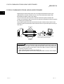
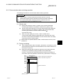
• While pressing the installation lever located at the bottom of module, insert the module fixing tab into
the fixing hole in the base unit until it stops. Then, securely mount the module with the fixing hole as
a supporting point.
If the module is not installed properly, it may cause the module to malfunction, fail or fall off.
Secure the module with screws especially when it is used in an environment where constant
vibrations may occur.
• Tighten the screws within the range of specified torque.
If the screws are loose, it may cause the module to fallout, short circuits, or malfunction.
If the screws are tightened too much, it may cause damage to the screw and/or the module,
resulting in fallout, short circuits or malfunction.
• Switch all phases of the external power supply off when mounting or removing the module.
Not doing so may cause damage to the module.
• Do not directly touch the conductive area or electronic components of the module.
Doing so may cause malfunction or failure in the module.
A-2
A-2
[Wiring Precautions]
!
CAUTION
• When turning on the power and operating the module after installation and wiring are completed,
always attach the terminal cover that comes with the product.
There is a risk of electric shock if the terminal cover is not attached.
• Perform correct pressure-displacement, crimp-contact or soldering for external wire connections
using the tools specified by the manufactures.
Incorrect connection may cause short circuits, fire, or malfunction.
• Attach connectors to the module securely.
• Be sure to fix communication cables or power supply cables leading from the module by placing
them in the duct or clamping them.
Cables not placed in the duct or without clamping may hang or shift, allowing them to be
accidentally pulled, which may cause a module malfunction and cable damage.
• Before connecting the cables, check the type o f interface to be connected.
Connecting or erroneous wiring to the wrong interface may cause failure to the module and
external devices.
• Tighten the terminal screws within the range of specified torque.
If the terminal screws are loose, it may result in short circuits or malfunction.
If the screws are tightened too much, it may cause damage to the screw and/or the module,
resulting in fallout, short circuits or malfunction.
• When removing the communication cable or power supply cable from the module, do not pull the
cable. When removing the cable with a connector, hold the connector on the side that is
connected to the module.
When removing the cable connected to the terminal block, first loosen the screws on the part
that is connected to the terminal block.
Pulling the cable that is still connected to the module may cause malfunction or damage to the
module or cable.
• Be careful not to let foreign matters such as sawdust or wire chips get inside the module.
They may cause fires, failure or malfunction.
• The top surface of the module is covered with protective film to prevent foreign objects such as
cable offcuts from entering the module when wiring.
Do not remove this film until the wiring is complete.
Before operating the system, be sure to remove the film to provide adequate heat ventilation.
A-3
A-3
[Starting and Maintenance Precautions]
!
CAUTION
• Do not disassemble or modify each module.
Doing so could cause failure, malfunction injury or fire.
• Switch all phases of the external power supply off when mounting or removing the module.
Not doing so may cause failure or malfunction of the module.
• Do not touch the connector while the power is on.
Doing so may cause malfunction.
• Switch all phases of the external power supply off when cleaning or retightening terminal screws
and module installing screws.
Not doing so may cause failure or malfunction of the module.
If the screws are loose, it may cause the module to fallout, short circuits, or malfunction.
If the screws are tightened too much, it may cause damages to the screws and/or the module,
resulting in the module falling out, short circuits or malfunction.
• Do not mount/remove the module onto/from base unit more than 50 times (IEC61131-2-
compliant), after the first use of the product.
Failure to do so may cause the module to malfunction due to poor contact of connector.
• Always make sure to touch the grounded metal to discharge the electricity charged in the body,
etc., before touching the module.
Failure to do so may cause a failure or malfunctions of the module.
[Operation Precautions]
!
CAUTION
• When performing the control of the PLC in operation (especially changing data, program, and
operation status (status control)) by connecting a personal computer, etc. to the intelligent
function module, read this manual carefully and confirm if the overall safety is maintained.
Failure to perform correct operation s to change data, program, or the status may result in
system malfunction, machine damage, or an accident.
[Disposal Precautions]
!
CAUTION
• When disposing of this product, treat it as industrial waste.
A-4
A-4
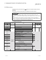
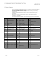
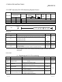
REVISIONS
The manual number is given on the bottom left of the back cover.
Print Date
Dec., 1999
Oct., 2000
Manual Number
Revision
SH (NA)-080007-A First Printing
SH (NA)-080007-B Add the contents of the function version B.
®
Put Windows base software products together from Mitsubishi
Programmable Logic Controller MELSEC series to Mitsubishi integrated
FA software MELSOFT series.
Standardize the name from software package (GPP function) to product
name (GX Developer).
Correction
Entire manual (change MELSECNET/10H to MELSECNET/H), Contents,
About the Manuals, About the Generic Terms and Abbreviations, Section
1.1, 1.2 POINT, Section 2.1, 2.2.1, 2.2.3, 2.2.5, 2.2.6, 2.3.1, 2.3.2,
Section 3.1.1, 3.2.3, 3.2.4, 3.3.1, 3.3.4, 3.3.5, 3.3.6, 3.4 (entire), Section
4.3, Chapter 9 (entire), Chapter 11 (entire), Section 12.2, 12.3, 12.4
(entire), 12.6 (entire), Section 13.3, 13.4, 13.6 (entire), Section 15.3,
Section 16.2 (entire) to 16.7
Jun., 2001
Addition
Section 2.4 (9), Section 3.2.3 POINT
SH (NA)-080007-C Standardize the name from utility package (QSCU) to product name (GX
Configurator-SC).
Correction
About the Manuals, The Manual's Use and Structure, About the Generic
Terms and Abbreviations, Program example (Section 9.4.1, 9.4.2, 9.4.3,
Section 11.5 (1) (2), Section 16.5, 16.6, 16.7), Section 1.1 (2) (diagram),
1.2, Chapter 3 (entire), Section 4.1 (2), Section 9.1.1 (4) 5), Section
11.3.2 (3), 11.3.3 (3), Section 13.6.1 (diagram)
Addition
Section 3.3.4, 3.3.6 (4), 3.4.5 (4)
Jan., 2003
SH(NA)-080007-D
Additional model
QJ71C24N,QJ71C24N-R2, QJ71C24N-R4
Correction
SAFETY PRECAUTIONS, About the Manuals, The Manual's Use and
Structure, About the Generic Terms and Abbreviations, Section 1.2,
Section 2.2.4 (2) (c), Section 3.3.1, 3.3.5, 3.3.6, 3.4.2, 3.4.3, 3.4.7,
3.4.8 (3), 3.5, Section 6.1, Section 7.1, 7.2, Section 9.1.1 (4), Section
10.4.1 (2) 1), Section 11.2.4 (2), 11.4.3 (a), 11.5, Section 15.1, 15.2,
15.3, 15.4.2, Section 17.1, 17.3, 17.4
Addition
Section 4.4.2 (6), Chapter 16 (entire)
Dec., 2003
SH(NA)-080007-E
Jun., 2004
SH(NA)-080007-F
A-5
Correction
About the Generic Terms and Abbreviations, Section 3.4.6 (4), Section
6.1, 6.3 (1) (b), Section 9.1.1 (4), Section 11.2.4 (2)
Correction
About the Generic Terms and Abbreviations, Section 3.3.4 (4), 3.4.3 (6),
3.4.4 (5), Section 8.2 (2), Section 11.3.1, Section16.2 (1)
A-5
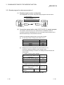
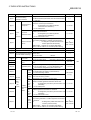
REVISIONS
The manual number is given on the bottom left of the back cover.
Print Date
Sep., 2004
Manual Number
SH(NA)-080007-G
Revision
Correction
Section 1.2, Section 6.1, Section 9.1.1
Addition
Section 17.8
Japanese Manual Version SH-080002-J
This manual confers no industrial property rights or any rights of any other kind, nor does it confer any patent
licenses. Mitsubishi Electric Corporation cannot be held responsible for any problems involving industrial property
rights which may occur as a result of using the contents noted in this manual.
1999 MITSUBISHI ELECTRIC CORPORATION
A-6
A-6
INTRODUCTION
Thank you for purchasing the MELSEC-Q series PLC.
Before using the equipment, please read this manual carefully to develop full familiarity with the functions
and performance of the Q series PLC you have purchased, so as to ensure correct use.
Please forward a copy of this manual to the end user.
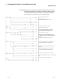
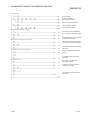
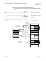
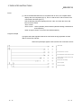
CONTENTS (This manual)
SAFETY PRECAUTIONS..............................................................................................................................A- 1
REVISIONS ....................................................................................................................................................A- 5
CONTENTS....................................................................................................................................................A- 7
About the Manuals .........................................................................................................................................A-14
The Manual's Use and Structure ...................................................................................................................A-15
About The Generic Terms and Abbreviations...............................................................................................A-17
Definitions and Descriptions of Terminology.................................................................................................A-19
1 OVERVIEW
1- 1 to 1- 6
1.1 Overview.................................................................................................................................................. 1- 1
1.2 Functions Added/Changed by Function Version B................................................................................ 1- 6
2 Using the PLC CPU Monitoring Function
2- 1 to 2-29
2.1 Overview.................................................................................................................................................. 2- 1
2.2 About the PLC CPU Monitoring Function............................................................................................... 2- 3
2.2.1 Data registration for using the PLC CPU monitoring function ........................................................ 2- 3
2.2.2 PLC CPU monitoring information .................................................................................................... 2- 3
2.2.3 Timing for PLC CPU monitoring ...................................................................................................... 2- 5
2.2.4 Timings of transmission and notification of monitoring results to the external device................... 2- 6
2.2.5 Transmission methods of monitoring results and transmission data to the external device..................... 2- 9
2.2.6 Execution sequence for using the PLC CPU monitoring function .................................................. 2-20
2.3 Settings for Using the PLC CPU Monitoring Function ........................................................................... 2-21
2.3.1 System setting items for the PLC CPU monitoring function ........................................................... 2-21
2.3.2 How to register and cancel the PLC CPU monitoring function....................................................... 2-26
2.4 Precautionary Notes for Using the PLC CPU Monitoring Function....................................................... 2-28
3 COMMUNICATIONS BY THE MODEM FUNCTION
3- 1 to 3-105
3.1 Overview.................................................................................................................................................. 3- 1
3.1.1 Features............................................................................................................................................ 3- 2
3.1.2 Function list....................................................................................................................................... 3- 5
3.1.3 Comparisons with related devices................................................................................................... 3- 6
3.2 System Configuration.............................................................................................................................. 3- 7
3.2.1 System configuration when performing data communication with an external device .................. 3- 7
3.2.2 System configuration when using the notification function ............................................................. 3- 8
3.2.3 System configuration when connecting GX Developer .................................................................. 3- 9
3.2.4 Precautions for system configurations ............................................................................................ 3-10
3.3 Specifications .......................................................................................................................................... 3-12
3.3.1 Transmission specifications ............................................................................................................. 3-12
3.3.2 Specification of connectable modems/terminal adapters ............................................................... 3-13
3.3.3 Compatibility with the QCPU remote password function ................................................................ 3-16
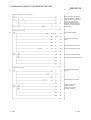
A-7
A-7
3.3.4 Compatibility with the callback function........................................................................................... 3-22
3.3.5 I/O signals with the PLC CPU.......................................................................................................... 3-31
3.3.6 Buffer memory.................................................................................................................................. 3-33
3.3.7 Precautions when using the modem function ................................................................................. 3-46
3.4 Start-up of the Modem Function ............................................................................................................. 3-52
3.4.1 Start-up procedures when communicating data with external devices .......................................... 3-52
3.4.2 Initial settings of the serial communication module......................................................................... 3-55
3.4.3 Register/read/delete of the initialization data .................................................................................. 3-58
3.4.4 Register/read/delete of the data for connection .............................................................................. 3-63
3.4.5 Initialization of modem/terminal adapter.......................................................................................... 3-68
3.4.6 Line connection ................................................................................................................................ 3-72
3.4.7 Data communication and notification............................................................................................... 3-78
3.4.8 Line disconnection............................................................................................................................ 3-84
3.5 Sample Programs ................................................................................................................................... 3-87
3.5.1 Sample program for data communication-1 .................................................................................... 3-88
3.5.2 Sample program for data communication-2 .................................................................................... 3-94
3.5.3 Sample program for notification..................................................................................................... 3-103
4 RECEIVING DATA WITH AN INTERRUPT PROGRAM
4- 1 to 4- 6
4.1 Settings for Receiving Data Using an Interrupt Program ...................................................................... 44.2 Interrupt Program Startup Timing ........................................................................................................... 44.3 Reception Control Method Using an Interrupt Program ........................................................................ 44.4 Programming........................................................................................................................................... 44.4.1 Program example............................................................................................................................. 44.4.2 Precautions when receiving data with an interrupt program .......................................................... 4-
2
2
3
4
4
5
5 CHANGING SEND AND RECEIVE DATA LENGTH UNITS TO BYTE UNITS
(WORD/BYTES UNITS SETTING)
5- 1 to 5- 2
6 CHANGING THE DATA COMMUNICATIONS MONITORING TIMES
6- 1 to 6-13
6.1
6.2
6.3
6.4
No-Reception Monitoring Time (timer 0) Setting ................................................................................... 6- 2
Response Monitoring Time (timer 1) Setting ......................................................................................... 6- 7
Transmission Monitoring Time (timer 2) Setting .................................................................................... 6-10
Message Wait Time Setting.................................................................................................................... 6-13
7 DATA COMMUNICATIONS USING DC CODE TRANSMISSION CONTROL
7- 1 to 7- 8
7.1 Control Contents of DTR/DSR (ER/DR) Signal Control ........................................................................ 7- 2
7.2 Control Contents of DC Code Control.................................................................................................... 7- 4
7.3 Precautions when Using the Transmission Control Functions.............................................................. 7- 7
8 DATA COMMUNICATIONS USING HALF-DUPLEX COMMUNICATIONS
8.1
8.2
8.3
8.4
8.5
8- 1 to 8- 8
Half-duplex Communications.................................................................................................................. 8Data Transmission and Reception Timing ............................................................................................. 8Changing the Communication System................................................................................................... 8Connector Connections for Half-duplex Communications..................................................................... 8Half-duplex Communications Precautions ............................................................................................. 8-
A-8
A-8
1
2
6
7
8
9 CONTENTS AND REGISTRATION OF THE USER FRAMES
FOR DATA COMMUNICATION
9- 1 to 9-20
9.1 User Frame Types and Contents During Communication .................................................................... 9- 1
9.1.1 User frames to be registered and used by the user........................................................................ 9- 1
9.1.2 Default registration frame (read only) .............................................................................................. 9- 9
9.2 Transmission/Reception Processing Using User Frame Register Data ............................................... 9-10
9.3 Precautions when Registering, Reading, Deleting and Using User Frames ........................................ 9-13
9.4 Register/Read/Delete User Frames ....................................................................................................... 9-15
9.4.1 Registering user frames................................................................................................................... 9-18
9.4.2 Reading user frames........................................................................................................................ 9-19
9.4.3 Deleting user frames ........................................................................................................................ 9-20
10 ON-DEMAND DATA COMMUNICATIONS USING USER FRAMES
10- 1 to 10- 9
10.1 User Frame Data Communications Function..................................................................................... 1010.2 User Frame Types and Registration .................................................................................................. 1010.3 User Frame On-Demand Data Transmission and Buffer Memory Used.......................................... 1010.4 On-Demand Function Control Procedure During User Frame Use .................................................. 1010.4.1 Data communication using the ASCII code ................................................................................ 1010.4.2 Data communications using the binary code .............................................................................. 1010.5 Example of an On-Demand Data Transmission Program Using User Frames................................ 1011 DATA COMMUNICATIONS USING USER FRAMES
1
2
2
4
4
6
8
11- 1 to 11-43
11.1 Overview of Data Communication Procedure.................................................................................... 11- 2
11.2 Data Reception ................................................................................................................................... 11- 3
11.2.1 About reception data .................................................................................................................... 11- 3
11.2.2 Timing for start/completion of data reception .............................................................................. 11-10
11.2.3 Receive procedure ....................................................................................................................... 11-14
11.2.4 User frame setting for reception .................................................................................................. 11-15
11.3 Receive Program ................................................................................................................................ 11-21
11.3.1 Sequence program example........................................................................................................ 11-21
11.3.2 Application example for data reception using a combination that specifies the first frame ....... 11-26
11.3.3 Application example for data reception using a combination that does not specify
the first frame................................................................................................................................ 11-32
11.4 Data Transmission .............................................................................................................................. 11-34
11.4.1 Send data ..................................................................................................................................... 11-34
11.4.2 Transmission procedure .............................................................................................................. 11-36
11.4.3 Settings for transmission user frames ......................................................................................... 11-37
11.5 Transmission program ........................................................................................................................ 11-41
12 TRANSPARENT CODES AND ADDITIONAL CODES
12- 1 to 12-20
12.1 Handling the Transparent Code and Additional Code Data .............................................................. 1212.2 Registering Transparent Codes and Additional Codes ..................................................................... 1212.3 Handling Transparent Codes and Additional Codes During Non Procedure Protocol Data
Communication ................................................................................................................................... 1212.4 Example of Data Communication Using the Non Procedure Protocol ............................................. 12-
A-9
A-9
1
2
3
8
12.4.1 Example of data reception ........................................................................................................... 12- 9
12.4.2 Example of data transmission...................................................................................................... 12-11
12.5 Handling Transparent Codes and Additional Codes During Bidirectional Protocol Data
Communication ................................................................................................................................... 12-13
12.6 Example of Data Communication Using the Bidirectional Protocol .................................................. 12-16
12.6.1 Example of data reception ........................................................................................................... 12-17
12.6.2 Example of data transmission...................................................................................................... 12-19
13 COMMUNICATING WITH ASCII CODE (ASCII-BIN CONVERSION)
13- 1 to 13-14
13.1 ASCII-BIN Conversion ........................................................................................................................ 13- 1
13.2 Settings for ASCII-BIN Conversion .................................................................................................... 13- 1
13.3 Performing ASCII-BIN Conversion for Data Communicated via Non Procedure Protocol .............. 13- 2
13.4 Example of Data Communication Using the Non Procedure Protocol ............................................. 13- 4
13.4.1 Example of data reception ........................................................................................................... 13- 5
13.4.2 Example of data transmission...................................................................................................... 13- 8
13.5 Performing ASCII-BIN Conversion for Data Communicated Via the Bidirectional Protocol ............ 13-10
13.6 Example of Data Communication Using the Bidirectional Protocol .................................................. 13-12
13.6.1 Example of data reception ........................................................................................................... 13-13
13.6.2 Example of data transmission...................................................................................................... 13-14
14 DATA COMMUNICATIONS USING EXTERNAL DEVICE AND PLC CPU M :
N CONFIGURATION
14- 1 to 14-11
14.1 Data Communications Precautions.................................................................................................... 1414.2 External Devices Interlock Conditions................................................................................................ 1414.2.1 Maximum communications time per external device station...................................................... 1414.2.2 Message structure when communicating data between external devices................................. 1414.3 Examples of Procedure for Data Communications with the PLC CPU............................................. 1414.3.1 Sequential data communications between external devices and the PLC CPU ....................... 1414.3.2 Data communications between PLC CPU and external devices by designating
a master station and slave stations ............................................................................................. 1415 SWITCHING THE MODE AFTER STARTING
1
3
3
4
6
6
9
15- 1 to 15-10
15.1 Mode Switching Operation and Contents that can be Changed ....................................................... 15- 2
15.1.1 Settings that can be changed with mode switching .................................................................... 15- 2
15.1.2 Operation for mode switching ...................................................................................................... 15- 2
15.2 Mode Switching Precautions .............................................................................................................. 15- 3
15.3 I/O Signals for Handshake with PLC CPU and Buffer Memory ........................................................ 15- 5
15.4 Switching the Mode from the PLC CPU............................................................................................. 15- 7
15.4.1 Mode switching procedure........................................................................................................... 15- 7
15.4.2 Mode switching sample program................................................................................................. 15- 8
15.5 Switching the Mode from an External Device .................................................................................... 15- 9
15.5.1 Mode switching procedure........................................................................................................... 15- 9
15.5.2 Mode switching sample program................................................................................................. 15-10
16 USING COMMUNICATION DATA MONITORING FUNCTION
16- 1 to 16-10
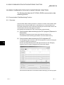
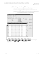
16.1 Communication Data Monitoring Function......................................................................................... 16- 1
16.1.1 Overview....................................................................................................................................... 16- 1
A - 10
A - 10
16.1.2 Communication data monitoring operation ................................................................................. 16- 2
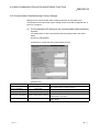
16.2 Communication Data Monitoring Function Settings .......................................................................... 16- 4
16.3 Communication Data Monitoring Example......................................................................................... 16- 8
17 DEDICATED INSTRUCTIONS
17.1
17.2
17.3
17.4
17.5
17.6
17.7
17.8
17- 1 to 17-31
Dedicated Instruction List ................................................................................................................... 17- 1
BUFRCVS Instruction ......................................................................................................................... 17- 2
CSET Instruction (PLC CPU Monitoring Register/Cancel)................................................................ 17- 5
CSET Instruction (Initial Settings)....................................................................................................... 17-11
GETE Instruction................................................................................................................................. 17-15
PRR Instruction ................................................................................................................................... 17-18
PUTE Instruction ................................................................................................................................. 17-21
UINI Instruction.................................................................................................................................... 17-25
INDEX
A - 11
Index- 1 to Index- 2
A - 11
(Related Manual-1) … Q Corresponding Serial Communication Module User's Manual (Basic)
SH-080006-H
1 OVERVIEW
1.1 Overview of the Serial Communication
Module
1.2 Features of the Serial Communication Module
1.3 About Added/Changed Functions in Function
Version B
2 SYSTEM CONFIGURATION AND AVAILABLE
FUNCTIONS
2.1 Applicable Systems
2.2 Combinations of PLC CPU and External
Device, and Available Functions
2.3 For Use in Multiple CPU System
2.4 For Use with Q00J/Q00/Q01CPU
2.5 For Use at MELSECNET/H Remote I/O
Station
2.6 Checking the Function Version, Serial No.,
and Software Version
3 SPECIFICATIONS
3.1 Performance Specifications
3.2 RS-232 Interface Specification
3.3 RS-422/485 Interface Specifications
3.4 Serial Communication Module Function List
3.5 Dedicated Instruction List
3.6 Utility Package (GX Configurator-SC)
Function List
3.7 List of GX Developer Setting Items for Serial
Communication Modules
3.8 List of Input/Output Signals for the PLC CPU
3.9 List of Applications and Assignments of the
Buffer Memory
4 SETTINGS AND PROCEDURES PRIOR TO
OPERATION
4.1 Handling Precautions
4.2 Settings and Procedures Prior to Operation
4.3 Part Names and Functions
4.4 External Wiring
4.5 Settings for GX Developer
4.6 Settings with the Utility Package (GX
Configurator-SC)
4.7 Individual Station Test
4.8 Loopback Test
4.9 Maintenance and Inspection
5 DATA COMMUNICATION USING THE MELSEC
COMMUNICATION PROTOCOL
5.1 Data Communication Functions
5.2 Utilizing the MX Component
6 DATA COMMUNICATION USING THE NON
PROCEDURE PROTOCOL
6.1 Data Reception from the External Device
A - 12
6.2 Sending Data to the External Device
6.3 Data Communications Precautions
7 DATA COMMUNICATION USING THE
BIDIRECTIONAL PROTOCOL
7.1 Data Reception from the External Device
7.2 Sending Data to the External Device
7.3 Processing when Simultaneous Transmission
Performed During Full-Duplex
Communications
7.4 Data Communications Precautions
8 UTILITY PACKAGE (GX Configurator-SC)
8.1 Functions Available with Utility Package
8.2 Installing and Uninstalling Utility Package
8.3 Explanation of Utility Package Operation
8.4 System Registration to Flash ROM
8.5 Auto Refresh Setting
8.6 Monitor/Test
8.7 Non Procedure Protocol Receive Data Clear
9 DEDICATED INSTRUCTIONS
9.1 Dedicated Instruction List
9.2 ONDEMAND Instruction
9.3 OUTPUT Instruction
9.4 INPUT Instruction
9.5 BIDOUT Instruction
9.6 BIDIN Instruction
9.7 SPBUSY Instruction
9.8 CSET (Receive data clear)
10 TROUBLESHOOTING
10.1 Checking the Status of the Serial
Communication Module
10.2 Error Code Tables
10.3 Troubleshooting by Symptom
APPENDIX
Appendix 1 Functional Improvements of the Q
Series C24
Appendix 2 QnA/A Series Module
Appendix 3 Processing Time
Appendix 4 ASCII-Code Table
Appendix 5 External Dimensions
Appendix 6 Example of Connection when a
Converter is Used
Appendix 7 Communication Support Tool (MX
Component)
Appendix 8 Example of Clear Process Program
for Receive Data
Appendix 9 Program Examples for Using Q
Series C24 at MELSECNET/H
Remote I/O station
Appendix10 Setting Value Recording Sheet
A - 12
(Related Manual-2) … Q Corresponding MELSEC Communication Protocol Reference Manual
SH-080008-F
1 OVERVIEW
1.1 Overview of the MELSEC Communication
Protocol
1.2 Features of the MELSEC Communication
Protocol
2 DATA COMMUNICATION USING THE MELSEC
COMMUNICATION PROTOCOL
2.1 Types and Applications of Data
Communication Frames
2.2 Accessible Range of Each Data
Communication Frames
2.3 How to Read the Control Procedures of the
MC Protocol
2.4 Access Timing of the PLC CPU Side
2.5 Setting Method for Writing to the PLC CPU
during RUN
2.6 Accessing Other Stations
2.7 Precautions on Data Communication
2.8 Time Chart and Communication Time of the
Transmission Sequence of the Serial
Communication Module
2.9 Transmission Time When Accessing Other
Stations Via MELSECNET/H, MELSECNET/10
2.10 Compatibility with Multiple CPU Systems
2.11 Compatibility with the Q00CPU, Q01CPU
Serial Communication Function
3 WHEN COMMUNICATING USING THE QnA
COMPATIBLE 3E/3C/4C FRAMES
3.1 Message Formats
3.2 List of Commands and Functions for the QnA
Compatible 3E/3C/4C Frames
3.3 Device Memory Read/Write
3.4 Buffer Memory Read/Write
3.5 Reading from and Writing to the Buffer
Memory of an Intelligent Function Module
3.6 PLC CPU Status Control
3.7 Drive Memory Defragmentation (for Other
Station QnACPU)
3.8 File Control
3.9 Registering, Deleting and Reading User
Frames: for Serial Communication Modules
3.10 Global Function: for Serial Communication
Modules
3.11 Data Transmission to an External device
(On-Demand Function): for Serial
Communication Modules
3.12 Initializing the Transmission Sequence: for
Serial Communication Modules
3.13 Mode Switching: for Serial Communication
Module
A - 13
3.14 Turning Off Displayed LEDs and Initializing
Communication Error Information and Error
Code: for Serial Communication Module
3.15 Turning Off the COM.ERR LED: for Ethernet
Modules
3.16 Loopback Test
3.17 Registering or Canceling PLC CPU
Monitoring: for Serial Communication
Modules
3.18 Remote Password Unlock/Lock
4 WHEN COMMUNICATING USING THE QnA
COMPATIBLE 2C FRAMES
4.1 Control Procedures and Message Formats
4.2 Contents of the Data Designation Items
4.3 List of Commands and Functions for QnA
Compatible 2C Frames
4.4 Precautions on the Data Communication
4.5 Example of Data Communication Using QnA
Compatible 2C Frames
5 WHEN COMMUNICATING USING THE A
COMPATIBLE 1C FRAMES
5.1 Control Procedures and Message Formats
5.2 Device Memory Read/Write
5.3 Extension File Register Read and Write
5.4 Reading and Writing in the Buffer Memory of
an Intelligent Function Module
5.5 Loopback Test
6 WHEN COMMUNICATING USING THE A
COMPATIBLE 1E FRAMES
6.1 Message Formats and Control Procedures
6.2 List of Commands and Functions for A
Compatible 1E Frames
6.3 Device Memory Read/Write
6.4 Extension File Register Read and Write
6.5 Reading and Writing in the Buffer Memory of
an Intelligent Function Module
APPENDIX
Appendix-1 Reading and Writing by Designation
of the Device Memory Extension
Appendix 2 Reading from and Writing to the
Buffer Memory
Appendix-3 Processing Time of the PLC CPU
Side While Communicating Using
the MC Protocol
A - 13
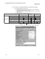
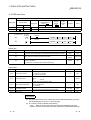
About the Manuals
The following manuals are available for this product.
Please order the desired manuals using the chart below.
Related Manuals
Manual number
(Model code)
Manual name
Q Corresponding Serial Communication Module User's Manual (Basic)
This manual explains an overview of the module and describes the applicable system configuration, the
specifications, the procedures prior to operations, the basic methods of communicating with the external
SH-080006
(13JL86)
device, maintenance and inspection, and the troubleshooting of the Q-series serial communication
module.
(Sold separately)
Q Corresponding MELSEC Communication Protocol Reference Manual
This manual explains information on how the external device reads data from and writes data to the PLC
CPU through communication using the MC protocol by utilizing the Q series C24/Q series E71.
SH-080008
(13JF89)
(Sold separately)
GX Configurator-SC Version 2 Operating Manual (Protocol FB support function)
This manual explains the function and usage of the protocol FB support function that supports the
creation of the data communication program of the module and set up of each parameter.
SH-080393E
(13JU46)
(Sold separately)
A - 14
A - 14
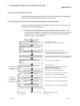
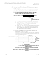
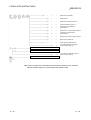
The Manual's Use and Structure
How to use this manual
This manual describes the use of special functions for the Q series C24
(QJ71C24N, QJ71C24N-R2, QJ71C24N-R4, QJ71C24, QJ71C24-R2), with each
chapter covering a specific function. Please read this manual and use the contents
below as a reference.
(1) To read an overview of special functions
• An overview of the major special functions is describes in Chapter 1.
(2) To use the function that monitors errors in the PLC CPU
• Chapter 2 describes the PLC CPU monitoring function, which monitors the
PLC CPU status and devices and automatically sends status information to
the opposite communicating device upon the occurrence of an error.
To use the PLC CPU monitoring function from the external device using
the MC protocol, refer to the reference manual for details on how to start
and cancel PLC CPU monitoring.
(3) To use the data communication function for the exchange of data with an
external device at a remote location
• Chapter 3 describes the specifications, procedures and other items regarding
communication using a modem function in order to exchange of data with an
external device at a remote location.
(4) To use the function for reading received data from the external device using an
interrupt program in order to reduce the scan time
• Chapter 4 describes the programming for execution of a receiving program
only when data from the external device is received.
(5) To use the function for monitoring the data communication time with the external
device
• Chapter 6 describes the function that monitors the data communication time
with the external device, along with the reception-interval time and the
response-reception time for transmission.
(6) To use the transmission control function to control data transmission/reception
with the external device.
• Chapter 7 describes the DTR/DSR control and the DC code function to control
the data communication with the external device.
(7) To use the function for simplifying the data communication program with the
registration data when preregistering the fixed-format section of the
communication message
• Chapters 9 to 11 describe the data transmission/reception function with user
frames in which the fixed-format section of the communication message has
been preregistered.
A - 15
A - 15
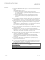
(8) To use the function that performs the data communication in ASCII code with
the external device
• Chapter 13 describes the handling of binary code on the PLC CPU and ASCIIBIN conversion function for communicating ASCII code data for an external
device.
(9) To use dedicated instructions
• Chapter 17 describes the dedicated instructions that are used to execute the
functions explained in this manual.
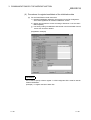
Structure of this manual
This manual describes how to use the utility package for the Q series C24 (GX
Configurator-SC) in order to perform the initial settings used to execute special
functions.
For details on the screens used for entering setting values, see Chapter 8 of
User's Manual (Basic).
A - 16
A - 16
About the Generic Terms and Abbreviations
This manual uses the following generic terms and abbreviations to describe the Q series C24 unless
otherwise specified.
(1) Generic terms and abbreviations
In this manual, the following generic terms and abbreviations are used to indicate
the PLC CPU and the Q series C24 used for the data-communication functions
of the serial communication modules. The model names of serial communication
modules are used to identify the specific models.
Generic term/abbreviation
Description of generic term/abbreviation
Ethernet modules
Q series E71 (E71)
Abbreviations for QJ71E71-100, QJ71E71-B5 and QJ71E71-B2 Ethernet interface modules
(Indicated as "E71" in diagrams)
Q series C24 (C24)
Abbreviations for QJ71C24N, QJ71C24N-R2, QJ71C24N-R4, QJ71C24 and QJ71C24-R2 serial
communication modules, and QJ71CM0 modem interface module (Indicated as "C24" in diagrams)
QC24
Generic term for AJ71QC24, AJ71QC24-R2, AJ71QC24-R4, A1SJ71QC24, A1SJ71QC24-R2
QC24N
Generic term for AJ71QC24N, AJ71QC24N-R2, AJ71QC24N-R4, A1SJ71QC24N, A1SJ71QC24NR2
QC24(N)
Generic term for QC24, QC24N
QCPU
Q mode
QCPU station
Abbreviation for PLC installed QCPU.
QnACPU
Generic term for Q2ACPU, Q2ACPU-S1, Q2ASCPU, Q2ASCPU-S1, Q2ASHCPU, Q2ASHCPU-S1,
Q3ACPU, Q4ACPU, Q4ARCPU
Q/QnACPU
Generic term for QCPU, QnACPU
UC24
Computer link modules
Generic term for AJ71UC24, A1SJ71UC24-R2, A1SJ71UC24-R4, A1SJ71UC24-PRF,
A1SJ71C24-R2, A1SJ71C24-R4, A1SJ71C24-PRF, A2CCPUC24, A2CCPUC24-PRF
A series computer link modules
Generic term for Q00JPUC, Q00CPU, Q01CPU, Q02CPU, Q02HCPU, Q06HCPU,
Q12HCPU, Q25HCPU, Q12PHCPU, Q25PHCPU
Generic term for the module below.
Serial communication modules
A - 17
QnA series
AJ71QC24, AJ71QC24-R2, AJ71QC24-R4, A1SJ71QC24, A1SJ71QC24-R2,
AJ71QC24N, AJ71QC24N-R2, AJ71QC24N-R4, A1SJ71QC24N, A1SJ71QC24N-R2
Q series
QJ71C24N, QJ71C24N-R2, QJ71C24N-R4, QJ71C24, QJ71C24-R2
A - 17
(2) Other generic terms and abbreviations
This manual uses the following generic terms and abbreviations to explain the
data-communication devices for the Q series C24. The names/model names are
provided when it is necessary to explicitly identify the model being discussed.
Generic term/abbreviation
Description of generic term/abbreviation
Buffer memory
Generic term for buffer memory of the intelligent function modules/special function modules used
for storing data sent to or received from the PLC CPU (setting values, monitor values, etc.)
Computer
Generic term for the external devices with which data can be sent/received using the MC protocol
or the bidirectional protocol.
Data communication functions
Generic term for MC protocol, non procedure protocol, and bidirectional protocol
GX Configurator-SC
Abbreviation for GX Configurator-SC (SW0D5C-QSCU-E or later).
• Initial settings for the module, monitoring and testing can be performed without using a
sequence program and without considering I/O signals or buffer memory. (Intelligent function
utility)
• Converting sequence programs necessary for data communication processing into FB can
shorten program production man-hours.
In addition, the monitoring and analysis of the transmitted/received data by the communication
network can shorten the system start-up time. (Protocol FB support function)
GX Developer
Abbreviation for GX Developer (SWnD5C-GPPW-E) (n in the model should be 4 or greater)
I/F
Abbreviation for Interface
Intelligent function modules
Generic terms for the Q series PLC modules that are operated by commands from the PLC CPU
(equivalent to the A series PLC special function modules).
Examples:
• CC-Link interface module
• A/D and D/A conversion modules
• Ethernet interface module
• Serial communication module
Intelligent function module devices
Generic terms for buffer memory of the intelligent function modules used for storing data sent to or
received from the PLC CPU (setting values, monitor values, etc.)
MELSECNET/10
Abbreviation for MELSECNET/10 network system
MELSECNET/H
Abbreviation for MELSECNET/H network system
MX Component
Abbreviation for MX Component (SWnD5C-ACT-E or later)
Operating Manual
(Protocol FB support function)
GX Configurator-SC Version 2 Operating Manual (Protocol FB support function)
Opposite devices
External devices
Generic term for Computers, indicators, measuring instruments, ID modules, bar code readers,
regulators, other serial communication modules, C24, etc. that are connected to the Q series C24
for data communication.
Reference manual
Q corresponding MELSEC communication protocol reference manual
RS-232 (Interface)
Abbreviation for Interface conforming to RS-232
RS-422/485 (Interface)
Abbreviation for Interface conforming to RS-422 and RS-485
Special function modules
Generic term for the A/QnA series PLC modules that are operated by commands from the PLC
CPU (equivalent to the Q series PLC intelligent function modules).
Examples:
• CC-Link interface module
• A/D and D/A conversion modules
• High-speed counter module
• Ethernet interface module
• Computer link module and serial communication module
Switch setting
Generic term for intelligent function module switch setting
User's manual (Basic) or Basic
Q corresponding serial communication module user's manual (Basic)
User's manual (Application) or
Application
Q corresponding serial communication module user's manual (Application)
A - 18
A - 18
Definitions and Descriptions of Terminology
The following table lists the definitions and descriptions of terminology used in this manual and related
manuals for the Q series C24.
Terminology
Description
One of the message formats for the serial communication modules for performing communication
using the MC protocol and ASCII code data.
This is the same message format as when communicating using the protocol for the A series
A compatible 1C frame
(Formats 1 to 4) computer link modules. Device memory read/write operations for the QCPU are allowed within the
device range of the AnACPU.
Details are explained in Chapter 5 of the Reference Manual.
Bidirectional protocol
A communication procedure for the serial communication modules and one of the data
communication functions for communicating any data between the PLC CPU and an opposite
device. Details are explained in Chapter 7.
Independent operation
A mode of interface operation to communicate data with external devices using a function
specified in each communication protocol setting. Two interfaces of serial communication
modules do not interact.
Linked operation
The operation mode of each of the two interfaces for a serial communication modules that are
connected to external devices and linked to one another in order to communicate data to/from the
external devices.
The two interfaces communicate data using the identical data-communication function (MC
protocol (identical format) or non procedure protocol) and the identical transmission specifications.
(Linked operation using the bidirectional protocol is not allowed.)
A communication procedure for the Q series serial communication modules or the Ethernet
interface modules, and a name of communication method for accessing to the PLC CPU from an
external device. (This is called the MC protocol in this manual.)
MELSEC communication protocol
(MC protocol) There are two communication methods; one uses ASCII code data and the other uses binary
code data.
Details are explained in the Reference Manual.
Message send function
This function registers character data (messages) to be sent to external devices (mainly printers)
in the serial communication modules as an user frame in advance, and sends the registered data
(Printer function) for multiple user frames using the non procedure protocol (sent by an instruction from the PLC
CPU).
Multidrop connection
A name of the connection when multiple external devices or other serial communication modules are
connected in a 1:n or m:n mode using the serial communication module's RS-422/485 interface.
Non procedure protocol
An user's communication procedure and one of the data communication functions for
communicating any data between the PLC CPU and an external device. Details are explained in
Chapter 6.
One of the message formats for the serial communication modules for performing communication
using the MC protocol and ASCII code data.
This is the same message format as the communication frame using the protocol for the QnA
QnA compatible 2C frame
(Formats 1 to 4) series serial communication modules.
• QnA compatible 2C frame (Formats 1 to 4): QnA simplified frame (Formats 1 to 4)
Details are explained in Chapter 4 of the Reference Manual.
One of the message formats for the serial communication modules for performing communication
using the MC protocol and ASCII code data.
QnA compatible 3C frame
This is the same message format as the communication frame using the protocol for the QnA
(Formats 1 to 4)
series serial communication modules.
QnA compatible 4C frame
• QnA compatible 3C frame (Formats 1 to 4): QnA frame (Formats 1 to 4)
(Formats 1 to 4)
• QnA compatible 4C frame (Formats 1 to 4): QnA extension frame (Formats 1 to 4)
Details are explained in Chapter 3 of the Reference Manual.
A - 19
A - 19
Terminology
QnA compatible 4C frame
User frame
A - 20
Description
One of the message formats for the serial communication modules for performing communication
using the MC protocol and binary code data.
This is the same message format as the communication frame using the protocol for the QnA
(Format 5) series serial communication modules.
• QnA compatible 4C frame (Format 5): QnA extension frame (Format 5)
Details are explained in Chapter 3 of the Reference Manual.
Data name when the fixed format portion of messages to be sent or received between a serial
communication module and an external device is registered in the module and used for sending
and receiving data with the functions listed below. (The contents of a user frame data should
conform to the specifications of the external device.)
The data array of the head and tail sections of a message (transmission control code, C24 station
number, sum check, fixed data, etc.) to be sent and received is registered in the serial
communication module before use.
• MC protocol on-demand function.
• Data-communication function using the non procedure protocol.
Details are explained in Chapter 9 of the User's Manual (Applications).
A - 20
MEMO
A - 21
A - 21
1 OVERVIEW
MELSEC-Q
1 OVERVIEW
1 1.1 Overview
This manual explains special functions of the MELSEC-Q series C24.
When applying the following program examples to the actual system, make sure to
examine the applicability and confirm that it will not cause system control problems.
This chapter provides an overview of these special functions. The primary special
functions of the Q series C24 and a functional overview are indicated below.
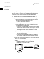
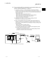
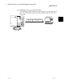
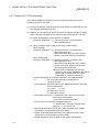
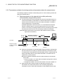
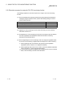
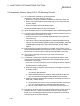
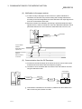
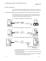
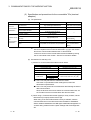
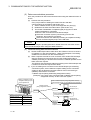
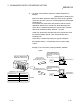
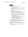
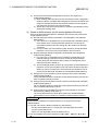
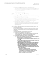
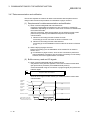
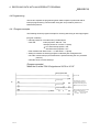
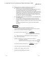
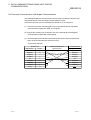
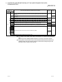
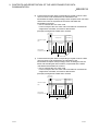
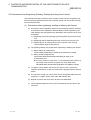
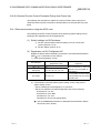
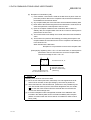
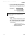
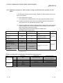
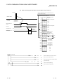
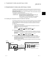
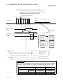
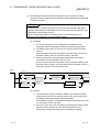
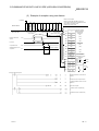
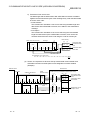
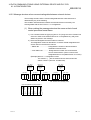
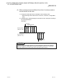
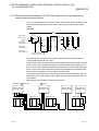
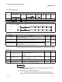
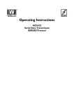
(1) Monitoring the PLC CPU (detailed explanation in Chapter 2)
(a) The local station PLC CPU can be monitored at time intervals set by the
user without a sequence program.
1) The following information can be registered as items to be monitored.
(Monitoring a device for the local station PLC CPU)
• A numeric value stored in a word device
• The ON/OFF status of a bit device
(Monitoring the status of the local station PLC CPU)
• Monitoring the status of the local station CPU module
2) For the results of the PLC CPU monitoring, the following monitored
information can be transmitted/notified.
• Transmission of information on the device to be monitored and status
of the PLC CPU (Monitoring information obtained through combined
use of the modem function can also be transmitted.)
• Notification of notification messages (character string data) registered
for connecting the modem function when using with the modem
function together
3) The user can select one of the following as transmission timing for the
PLC CPU monitoring results to the external device.
• Transmission/notification each time the PLC CPU is monitored.
(Constant cycle transmission)
• Transmission/notification when the information read from the PLC
CPU agrees with conditions set by the user. (Condition agreement
transmission)
(b) The PLC CPU monitoring function can be used in communication using MC
protocol or non procedure protocol.
(c) Using the PLC CPU monitoring function makes it possible to do the
following:
• Sends device data without using a sequence program
• Simplifies the device monitor procedure
• Sends CPU module error information
Q25HCPU
MELSEC
POWER
MODE
RUN
QJ71C24
CH1.
ERR.
External device
CH2.
CH1.
USER
BAT.
BOOT
CPU error
information
RS-232
Monitoring
device information
CH.2
SDA
1
SG
PULL
USB
SDB
2
(FG)
RDA
3
4
(FG)
RS-232
RDB
RS-422
/485
MITSUBISHI
Abnormal detection
5
6
7
Error
occurrence
1-1
1-1
1 OVERVIEW
MELSEC-Q
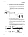
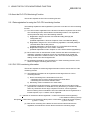
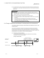
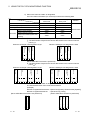
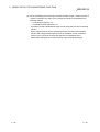
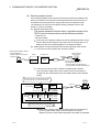
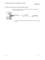
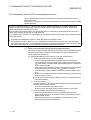
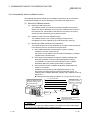
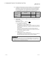
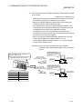
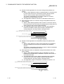
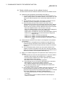
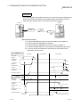
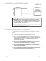
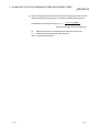
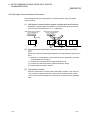
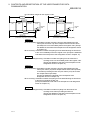
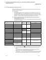
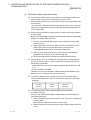
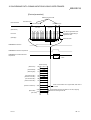
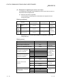
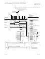
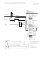
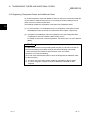
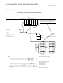
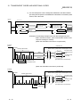
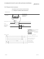
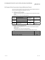
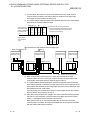
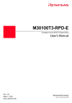
(2) Communicating with the external device at a remote location via a
modem (detailed explanation in Chapter 3)
1) Connecting a modem or TA (terminal adapter) to the RS-232 interface
facilitates communication via a public line/private line/digital line (ISDN), such
as data communication with a device at a remote location (listed below) and
calling a pager device.
• Data communication using the MC protocol
• Data sending and receiving using the non procedure protocol
• Data communication using the bidirectional protocol
• PLC access using the GX Developer
2) Initialization of a modem or TA, line connection (dialing), and line
disconnection are performed by the PLC CPU.
3) When a remote password is set in the QCPU with the GX Developer, the
following access from the external device to QCPU using the Q series C24
modem function can be performed by executing the unlock processing to the
remote password.
• Data communication using MC protocol
• Accessing the PLC using the GX Developer
The remote password function is a QCPU function designed to prevent
improper access to the QCPU by users.
The QCPU remote password function can be used by setting a remote
password in the QCPU with the GX Developer.
Q series C24
Modem/TA ( 1)
Modem/TA ( 1)
External device
RS-232
Pager receiver
1 TA is an abbreviation for Terminal Adapter.
1-2
1-2
1
1 OVERVIEW
MELSEC-Q
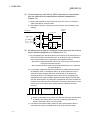
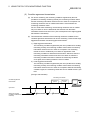
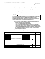
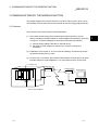
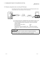
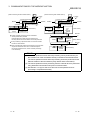
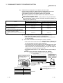
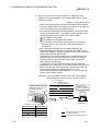
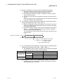
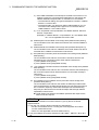
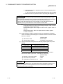
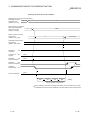
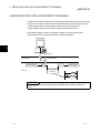
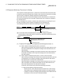
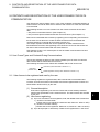
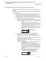
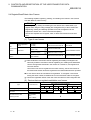
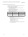
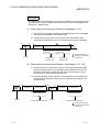
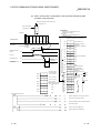
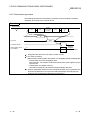
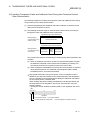
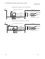
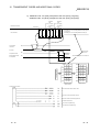
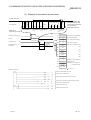
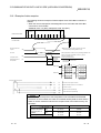
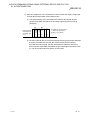
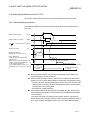
(3) Receiving data with an interrupt program (detailed explanation in
Chapter 4)
1) In data communication between the Q series C24 and the external device,
data can be received using an interrupt program with the following data
communication functions.
• Data reception during communication using the non procedure protocol
• Data reception during communication using the bidirectional protocol
2) Receiving data using an interrupt program expedites data reception by the
PLC CPU.
Q series C24
Data
transmission
Receive
Interrupt issued
Main program
Main program
Interrupt
program executed
PLC CPU
FEND
SM400
I
BUFRCVS
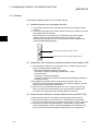
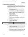
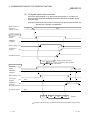
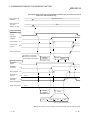
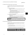
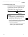
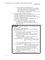
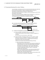
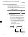
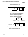
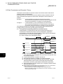
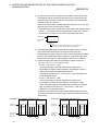
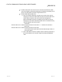
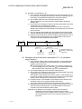
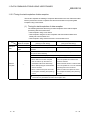
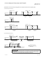
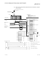
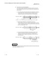
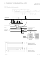
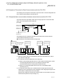
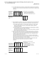
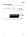
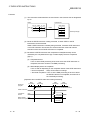
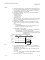
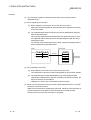
(4) Controlling data communication in accordance with the external
device (detailed explanation in Chapter 7)
1) The Q series C24 controls data communication with the external device by
turning ON/OFF the DTR/DSR signal and sending/receiving the DC code.
2) DTR/DSR signal control
Using the DTR (ER) and DSR (DR) signals, the external device is notified of
whether or not data communication can be performed.
3) DC code control
By sending/receiving the DC1 and DC3 code data, the external device is
notified of whether or not data can be received. By enclosing the user data
with the DC2 and DC4 code data, the external device is notified of the valid
transmission data range.
External
device side
(Interruption)
(Restart)...From the succeeding data
Data 1-2
Data 1-1
Data 2-1
PLC CPU
side
Data 2-2
(Interruption)
(Restart)...From the
succeeding
data
DTR signal
DSR signal
External
device side
PLC CPU side
1-3
Data 1-1
D
C
3
D
C
3
Data 2-1
(Restart)...From the succeeding data
(Interruption)
Data 1-2
D
C
1
D
C
1
Data 2-2
(Restart)...From the
(Interruption)
succeeding
data
1-3
1 OVERVIEW
MELSEC-Q
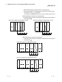
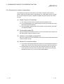
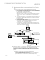
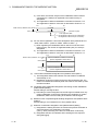
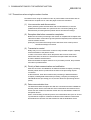
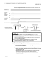
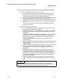
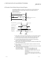
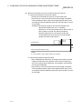
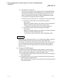
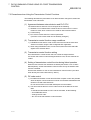
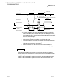
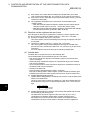
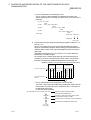
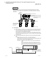
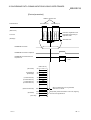
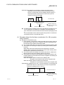
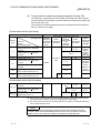
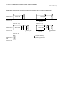
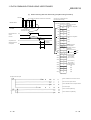
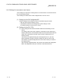
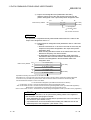
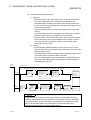
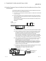
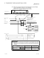
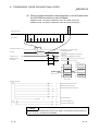
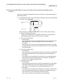
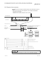
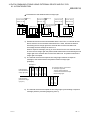
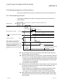
(5) Converting binary code data to ASCII code data to communicate
with the external device specification (detailed explanation in
Chapter 13)
1) Binary code data that is processed by the PLC CPU can be converted to
ASCII code data for communication.
2) ASCII-BIN conversion is performed by the Q series C24 according to user
settings.
External
device
Q series C24
Does not convert
Head data
Buffer memory
H
L
1234H
H
34H 12H
(34H)
Converts
(12H)
L
L
H
(3) (4) (1) (2)
33H 34H 31H 32H
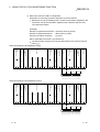
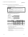
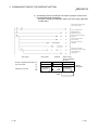
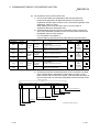
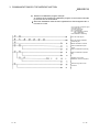
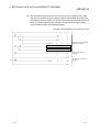
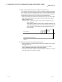
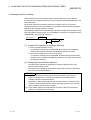
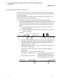
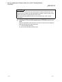
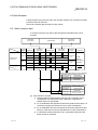
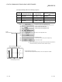
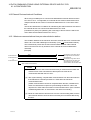
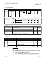
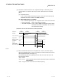
(6) Sending/receiving data in a message format tailored to the external
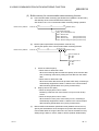
device (detailed explanation in Chapters 9 to 11)
First frame
Self-station
number
Destination
station number
ENQ
Password
1) By preregistering the data arrangement (user frames) of the messages to be
sent and received by the external device, to the Q series C24, the following
data communications can be performed using registered frames.
• MC protocol: Data transmission from the PLC CPU to the external device
using the on-demand function
• Non procedure protocol: Data communication between the PLC CPU and
the external device
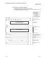
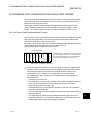
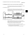
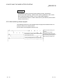
2) For example, multiple first frames and last frames (called user frames) with
the definition shown in the diagram below can be preregistered in the Q
series C24. When sending data to the external device, the data that is
arranged as shown in the diagram below can be sent by designating the
preregistered user frame numbers and arbitrary data. When receiving data
from the external device, by setting the preregistered user frame numbers for
reception at the startup of the Q series C24, the arbitrary data section can be
read to the PLC CPU when the message with the registered content is
received.
Arbitrary data
CR
LF
Last frame
Before sending data, the Q series C24 adds the first frame and last frame
to arbitrary data. When data is received, the arbitrary data section is
stored in the buffer memory as receive data.
3) User frames and various setting values for data communication with the
external device can be preregistered to the Q series C24 flash ROM.
1-4
1-4
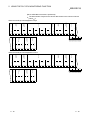
1 OVERVIEW
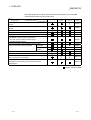
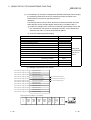
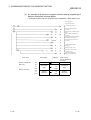
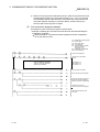
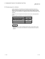
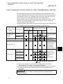
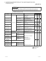
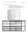
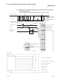
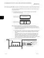
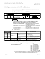
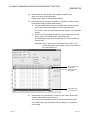
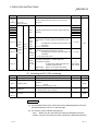
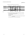
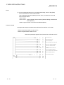
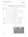
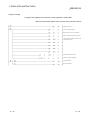
MELSEC-Q
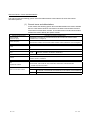
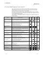
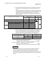
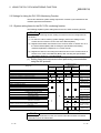
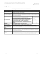
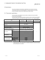
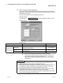
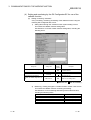
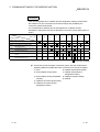
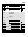
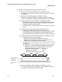
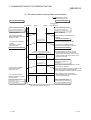
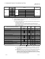
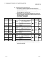
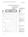
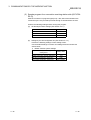
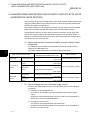
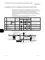
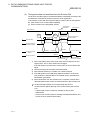
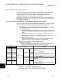
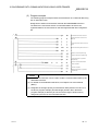
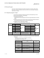
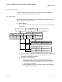
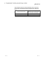
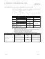
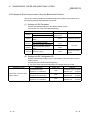
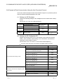
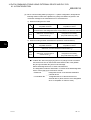
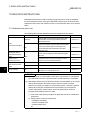
The following table shows which special functions are available for the main data
communication functions of the Q series C24.
Main data communication functions
Special functions
MC protocol
Non procedure
protocol
Bidirectional
protocol
Monitoring of the PLC CPU using the PLC CPU monitoring
Reference
section
Chapter 2
function
Data communication to a remote location using the modem
Chapter 3
function
Reading received data using an interrupt program
Chapter 4
Changing the unit of the data length for communication data
Chapter 5
Changing the monitoring time for data communication
Chapter 6
Transmission control for data communication
Chapter 7
• DC code control (Including Xon/Xoff control)
• DTR/DSR (ER/DR) control
Data communication using half-duplex communication
Data communication using user frames
Chapter 8
Registration
Chapter 9
Transmission,
Chapter 10
reception
Chapter 11
Data communication using the transparent code
Chapter 12
Communication using ASCII code data by ASCII-BIN conversion
Chapter 13
Data communication with multiple external devices using a multi-
Chapter 14
drop connection (m:n connection)
Changing the interface mode after starting data communication
Chapter 15
(Changes to communication protocol and transmission
specifications)
: Available
1-5
: Not available
1-5
1 OVERVIEW
MELSEC-Q
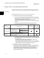
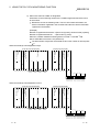
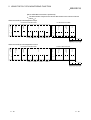
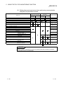
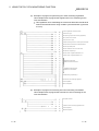
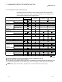
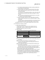
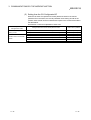
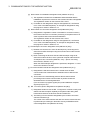
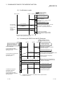
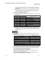
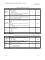
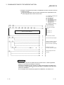
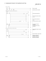
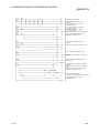
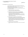
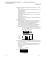
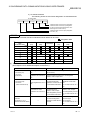
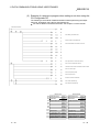
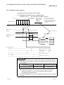
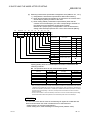
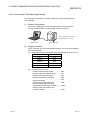
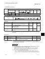
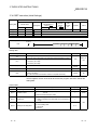
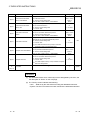
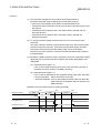
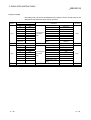
1.2 Functions Added/Changed by Function Version B
Of the special functions for the Q series C24 described in this manual, functions
added/changed in the Q series C24 of the function version B and communication
functions that can use those functions are listed below.
See Section 2.6 for the function version, serial NO. and software version of products
(CPU module, GX Developer, GX Configurator-SC) related to the Q Series C24 which
can use added/changed functions.
See Appendix 1.1 concerning a comparison of functions in the different Q Series C24
function versions.
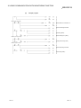
Function
Description of function
MC
Non
procedure
Bidirectional
Explanation
chapter
Transmission of PLC CPU
monitoring information through
combined use of the modem
function
In the PLC CPU monitoring function, PLC CPU monitoring information is
transmitted to the external device via a modem.
Remote password check
When accessing the QCPU from a remote location for the following data
communication using the Q series C24 modem function, data communication
is enabled after the unlock processing to a remote password set in the QCPU
is completed normally from the external device.
• Communication using MC protocol
• Communication using the GX Developer
Automatic initialization for
modem
Initializes the modem automatically when Q Series C24 starts up.
Callback
After line connection from the GX Developer, access to the QCPU from the
GX Developer is made possible through line reconnection from the Q Series
C24 (callback). Transmission costs after line connection from the Q Series
C24 side are borne by the Q Series C24 side.
Addition of non reception
monitoring time format in non
procedure protocol
This function allows messages to be received in the non reception protocol by
time-out in non reception monitoring time (timer 0) if the received complete
code and received data count have been not determined.
Chapter 6
Transmission control start/end
free area designation
This function allows the designation of the available capacity of the OS area
that notifies the data reception failure at the time of transmission control
(DTR/DSR signal control and DC code control).
Chapter 7
Registration, etc. of the following codes can be executed as the changeable
Adding changeable user frame data of user frames for data communication.
data
• Horizontal parity code
• Sum check code of two’s-complement number
Chapter 9
Chapter 2
Chapter 3
Adding the receive function
using user frames
When specifying the first frame and executing data reception, a message
comprised of the first frame and arbitrary data can be received.
For each combination of receiving user frame that the user has set, any data
length can be specified for the arbitrary data.
(Setting the data length for the arbitrary data to "0" makes it possible to
receive 1 byte only such as ACK/NAK).
Chapter
11
Multiple designations of send
transparent codes
When executing data transmission using the following protocol, it is possible to
designate a maximum of 10 types of sending transparent codes for each
interface.
• Non procedure protocol
• Bidirectional protocol
Chapter
12
Switching to the GX Developer
This functions allows the GX Developer connection mode to be switched by
connection mode by switching
an external device or the PLC CPU.
the mode
Chapter
15
Communication data
monitoring function
This function allows the monitoring of communication data transmitted on the
communication network of the Q series C24 and an external device.
Chapter
16
UINI instruction
The UINI instruction allows change of the mode, transmission specifications
and host station No. of the Q series C24.
Chapter
17
: Can be used
1-6
: Cannot be used
1-6
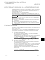
2 USING THE PLC CPU MONITORING FUNCTION
MELSEC-Q
2 USING THE PLC CPU MONITORING FUNCTION
This chapter explains the PLC CPU monitoring function with which the Q series C24
monitors the PLC CPU based on the monitoring information reregistered by the user.
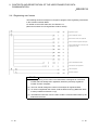
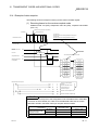
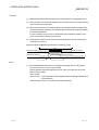
2.1 Overview
2
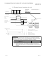
The following explains an overview of the PLC CPU monitoring function:
(1) Transmission without using a sequence program
1) The PLC CPU monitoring function enables the Q series C24 to monitor the
local station's PLC CPU at time intervals set by the user by reregistering data
to be used for the PLC CPU monitoring function.
Data transmission and notification to the external device is possible by
communication using the MC or non procedure protocol without using a sequence
program.
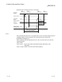
2) The following monitoring information selected by the user can be sent or
notified to the external device as the PLC CPU monitoring results.
Combined use of
Monitoring result
Without the
the modem
modem function
function (modem
communication)
Local station PLC CPU
Data transmission
device (information on the
device to be monitored)
Numeric value stored in a
word device
ON/OFF status for a bit
device
Status of the local station PLC CPU module
Notification
Notification message registered in data for connection
(character string data)
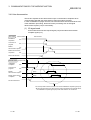
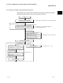
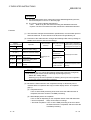
3) Two separate timings--constant-cycle transmission and condition-agreement
transmission--are used to transmit and notify the PLC CPU monitoring results
to the external device.
• In the constant cycle transmission, transmission and notification are
performed each time the PLC CPU is monitored.
• In the condition agreement transmission, transmission and notification are
performed when the information read from the PLC CPU satisfies the userdefined conditions and an error is detected in the PLC CPU.
(2) Simplifying the device monitoring procedure
When device monitoring is performed by communication using the MC protocol,
the external device must repeatedly perform monitor request transmission and
monitor data reception processing after it executes monitor registration.
By designating the constant cycle transmission for the PLC CPU monitoring
function, the device data can be monitored without performing the monitor
request reception processing.
2-1
2-1
2 USING THE PLC CPU MONITORING FUNCTION
MELSEC-Q
(3) Notification of an error in the PLC CPU
In the condition agreement transmission and notification, error information can be
sent to the external device without a sequence program whenever a PLC CPU
error occurs.
Q25HCPU
MELSEC
POWER
MODE
RUN
QJ71C24
External device
CH2.
CH1.
ERR.
CH1.
USER
2
BAT.
BOOT
CPU error
information
RS-232
Monitoring device
information
CH.2
SDA
1
SG
PULL
USB
SDB
2
(FG)
RDA
3
4
(FG)
RS-232
RDB
RS-422
/485
MITSUBISHI
Abnormal detection
5
6
7
Error
occurrence
2-2
2-2
2 USING THE PLC CPU MONITORING FUNCTION
MELSEC-Q
2.2 About the PLC CPU Monitoring Function
This section explains the PLC CPU monitoring function.
2.2.1 Data registration for using the PLC CPU monitoring function
The following explains the data registration by the user to use the PLC CPU monitoring
function.
(1) PLC CPU monitor registration for the Q series C24 that is required to use the PLC
CPU monitoring function is described in the following sections. The registration
can be performed using one of the following methods:
1) Registration using the Q series C24 dedicated utility package (GX
Configurator-SC)
(Detailed explanation is found in Chapter 8 of the User's Manual (Basic))
2) Registration using the PLC CPU monitoring registration command (0630) for
communication with the MC protocol
(Detailed explanation is found in Section 3.17 of the Reference Manual)
3) Registration using the PLC CPU "CSET" instruction
(Detailed explanation found in Chapter 17 of the User's Manual (Application))
(2) When this function is used with the modem function and data is transmitted or a
notification message is notified as a PLC CPU monitoring result, register the
connection data for the modem function on the "PLC CPU monitoring system
setting" screen of the GX Configurator-SC.
(3) By registering the data for using the above PLC CPU monitoring function, the Q
series C24 begins monitoring the PLC CPU.
2.2.2 PLC CPU monitoring information
This section explains the monitoring target information used to execute the PLC CPU
monitoring function.
(1) The following information can be registered as the target of the PLC CPU
monitoring function.
1) Device monitoring for the local station's PLC CPU
• Monitoring of the numeric values stored in the word device
• Monitoring of the bit device ON/OFF status
2) Monitoring of the local station's PLC CPU status
(2) In monitoring word and bit devices, a maximum total device point value of 960
(equivalent to a maximum of 15360 bits for only bit devices), or a total of 10 blocks
when any continuous device range comprises one block, can be registered.
Since monitoring of the local station's PLC CPU status will also be registered as a
one-block portion, up to 11 blocks can be registered.
11 ≥ (Number of word device blocks registered + number of bit device blocks registered)
+ CPU status monitoring (1 block)
960 points ≥ (Total number of all word device block points + total number of all bit device block points)
(1 point = 1 word)
(1 point = 16 bits)
(3) With device monitoring of the blocks for which the word and bit devices are
registered, the head device of each block becomes the monitoring target.
2-3
2-3
2 USING THE PLC CPU MONITORING FUNCTION
MELSEC-Q
(Example1) For a block in which 10 points of word devices from D100 to D109 are
registered
Monitoring target: Numeric value stored in D100
Data transmitted: Numeric values stored in D100 to D109
(Example2) For a block in which two points of bit devices from M100 to M131 are
registered
Monitoring target: ON/OFF status of M100
Data transmitted: ON/OFF status of M100 to M131
(4) The word and bit devices that can be designated as the monitoring targets and the
device codes that are used to register the monitoring devices are shown in the table
below.
Register the devices using the existing device ranges.
Classification
Internal system
Device
Device range
(Default)
Binary
Special relay
SM
91H
Special register
SD
A9H
Input
X
9CH
Output
Y
9DH
Internal relay
M
90H
Latch relay
L
92H
Annunciator
F
93H
Edge relay
V
94H
Link relay
B
A0H
Data register
D
A8H
0 to 12287
Link register
W
B4H
0 to 1FFFH
Internal user
Retentive timer
Word
Device code
ASCII
Timer
Contact
TS
C1H
Coil
TC
C0H
Current value
TN
C2H
Contact
SS
C7H
Coil
SC
C6H
Current value
SN
C8H
0 to 2047
0 to 1FFFH
0 to 8191
0 to 2047
0 to 1FFFH
0 to 2047
Contact
CS
C4H
Coil
CC
C3H
Current value
CN
C5H
Link special relay
SB
A1H
Link special register
SW
B5H
Step relay
S
98H
0 to 8191
Direct input
DX
A2H
0 to 1FFFH
Direct output
DY
A3H
Index register
Z
CCH
R
AFH
0 to 32767
ZR
B0H
0 to FE7FFH
Counter
Register
Device type
Bit
File register
0 to 1023
0 to 7FFH
0 to 15
POINT
(1) Designating a non-existent device code will result in an error.
(2) When the device range in the parameter setting has been changed, the new
device range can be set as the PLC CPU's monitoring target.
2-4
2-4
2 USING THE PLC CPU MONITORING FUNCTION
MELSEC-Q
2.2.3 Timing for PLC CPU monitoring
The following explains the timing for PLC CPU monitoring when the PLC CPU
monitoring function is executed.
(1) PLC CPU monitoring using the Q series C24 is performed continuously at cycle
time intervals registered by the user.
(2) Values from 1 to 65535 (unit: 100ms/s/min) can be registered as the cycle time.
Use the following expressions as a reference when registering the cycle time.
(a) When sending device data or the PLC CPU status
Cycle time designation > K + sequence scan time + processing time
+ data transmission time
(b) When notifying through combined use of the modem function
(when notifying)
Cycle time designation > K + sequence scan time + processing time
+ data transmission time
+ data transmission delay time of the modem
+ modem connection and disconnection time
(when sending data)
Cycle time designation > K + sequence scan time + processing time
+ data transmission time
+ data transmission delay time of the modem
+ modem connection and disconnection time
+ circuit disconnection wait time
When modem initialization has not been
performed, the modem initialization time will be
added. (We recommend that the modem
initialization be performed in advance.)
The items that appear in the above expressions are explained below:
• K
: 60 ms constant (internal processing time of
the Q series C24)
• Processing time: Processing time for the "Multiple block batch read word
unit command 0406"
For 1 point
: 11.3 ms
For 480 points: 23.4 ms
For 960 points: 36.2 ms
• Data transmission time = 1 / transmission rate × bit count for one byte
portion during transmission
× byte count for transmission data
• Bit count for one byte portion during transmission =
1 + data bit count + parity bit + stop bit count
(parity bit = 1, no parity bit = 0)
• Data transmission delay time by the modem: Depends on the modem
specifications, line specifications and line status.
• Modem connection and disconnection time: Depends on the modem
specifications, line specifications and line status.
• Modem initialization time: Depends on the modem specifications.
2-5
2-5
2 USING THE PLC CPU MONITORING FUNCTION
MELSEC-Q
(3) To monitor the PLC CPU, the Q series C24 reads monitoring information (device
information, PLC CPU status information) from the PLC CPU at time intervals set
by the user.
POINT
(1) Since the Q series C24 reads the monitoring information (device data, PLC
CPU status) at the time of the next PLC CPU END process after the cycle time
elapses, make the cycle time as long as possible.
(2) The following should be considered if the cycle time is short.
• The scan time of the PLC CPU is longer and the number of scan cycles has
increased.
• The increase in the processing time of the Q Series C24 PLC CPU
monitoring function has increased causing an increase in the processing
time of other data communication functions.
• The load on the external device has increased.
2.2.4 Timings of transmission and notification of monitoring results to the external device
The following explains the timings for the transmission and notification of the PLC CPU
monitoring results.
There are two transmission methods for transmitting and notifying the monitoring
results of the local station PLC CPU to the external device. These include constant
cycle transmission and condition agreement transmission. One of these methods must
be selected by the user during PLC CPU monitoring registration.
(1) Constant cycle transmission
The monitoring results are transmitted and notified each time monitoring
information is read from the PLC CPU.
(Timing to transmit data)
Monitoring information
Constant cycle
transmission
One-block
portion
•••
One-block
portion
External device
Cycle time
Sequence program
END
2-6
END
END
END
2-6
2 USING THE PLC CPU MONITORING FUNCTION
MELSEC-Q
(2) Condition agreement transmission
(a) For device monitoring, the monitoring conditions registered by the user
(conditions for sending monitoring results), the monitoring condition values
and the monitoring information read from the PLC CPU are compared. The
monitoring results are sent or notified when there is a block where the
monitoring conditions match.
For PLC CPU status monitoring, the monitoring results are sent or notified
only once when an error is detected for the first time from the status
information read from the PLC CPU. (This corresponds to the edge triggered
transmission noted below).
(b) Two transmission methods of the monitoring results are available for the
condition agreement transmission for device monitoring. These include edge
triggered transmission and level triggered transmission.
1) Edge triggered transmission
The monitoring conditions registered by the user (conditions for sending
monitoring results), the monitoring condition values and the monitoring
information read from the PLC CPU are compared. The monitoring
results are sent or notified only once when an agreement of the
monitoring conditions is detected for the first time. After that, when the
monitoring information read from the PLC CPU does not match the
monitoring conditions and then it matches the monitoring conditions
once again, the monitoring results are sent or notified.
2) Level triggered transmission
The monitoring conditions registered by the user (conditions for sending
monitoring results), the monitoring condition values and the monitoring
information read from the PLC CPU are compared. While the monitoring
conditions agree, the monitoring results are sent or notified at each cycle
time.
(Timing to transmit data)
Monitoring information
Condition agreement
transmission
One-block
portion
•••
One-block
portion
External device
Cycle time
Sequence program
(conditions matched/not
matched)
2-7
Matched
END
Not matched
END
Matched
END
2-7
2 USING THE PLC CPU MONITORING FUNCTION
MELSEC-Q
(c) In the condition agreement transmission for device monitoring, the head device
for each block is the monitoring target for condition monitoring of each block
device.
For the condition agreement transmission, the monitoring conditions that can be
designated for the device to be registered by the user and the registration values
when designating the monitoring condition are shown in the table below.
Register the monitoring conditions for the head device of each block using
the following table.
Registration value
Monitoring condition (item to be judged)
Device value or status = device monitoring condition value or status
Device value or status ≠ device monitoring condition value or status
Monitoring device < monitoring condition value
Unsigned
Signed
For edge triggered
transmissions
For level triggered
transmissions
0001H
0101H
0002H
0102H
0003H
0103H
Monitoring device < monitoring condition value
Monitoring device > monitoring condition value
0004H
0104H
0005H
0105H
Monitoring device > monitoring condition value
Monitoring device < monitoring condition value
0006H
0106H
0007H
0107H
Monitoring device < monitoring condition value
Monitoring device > monitoring condition value
0008H
0108H
0009H
0109H
Monitoring device > monitoring condition value
000AH
010AH
Valid designated
device
Bit
Word
(d) In device monitoring, register the monitoring condition value or status when
the Q series C24 judges that the numeric value/status of the monitoring
device for condition agreement transmission (head device of each block)
agrees with the condition using the registration values shown below.
Type of monitoring device
Bit device
Word device
Monitoring condition value or
status
Registration value
OFF
0000H
ON
0001H
Numerical value
0000H to FFFFH
(Example 1) When M0 = ON is the condition agreement
Monitoring condition registration value
: 0001H
Registration value for the monitoring condition value or status: 0001H
(Example 2) When D0 > 100 (signed) is the condition agreement
Monitoring condition registration value
: 000AH
Registration value for the monitoring condition value or status: 100(64H)
REMARK
In status monitoring for the PLC CPU, the monitoring conditions and condition
values for condition agreement transmission are not registered. Instead, it is
registered as whether or not PLC CPU status monitoring will be performed.
Monitoring results in condition agreement transmission are sent or notified only once
when an error is detected by the status information read from the PLC CPU for the
first time.
2-8
2-8
2 USING THE PLC CPU MONITORING FUNCTION
MELSEC-Q
2.2.5 Transmission methods of monitoring results and transmission data to the external device
The following explain the method of transmitting the PLC CPU monitoring results and
data to the external device.
(1) Data transmission to the external device while performing
communication using the MC protocol
(a) The same format as for the messages sent with the on-demand function is
used to transmit data, except that the on-demand data section is replaced
with the device information and PLC CPU status information. The data is
sent as explained in (c) and (d) below.
(Detailed explanation is found in Section 3.17 of the Reference Manual)
When the interface that is to use the modem function is set in the MC
protocol, connection processing and disconnection processing to the modem
are performed when the PLC CPU monitoring results are transmitted.
(Example) Data transmission by MC protocol with modem function (condition
agreement transmission)
Dial
Registration information
for PLC CPU monitoring
Disconnection
Cycle time
Sequence program
(conditions matched/
not match)
External device
END
END
END
Matched
Not matched
Matched
(b) When the transmission of on-demand data using user frames is designated,
the same format as for sending on-demand data using user frames is used
to transmit data, except that the on-demand data section is replaced with the
device information and PLC CPU status information. The data is sent as
explained in (c) and (d) below.
See the following explanatory items for data reception by the external
device side.
• Device information, PLC CPU status information arrangement: Section
3.17 of the Reference Manual
• Arrangement of data in the user frame section to be sent: Chapter 10
(c) When sending the monitoring results as data during constant cycle
transmission, the entire block portion of the monitoring target device
information and PLC CPU status information is transmitted in batch mode.
2-9
2-9
2 USING THE PLC CPU MONITORING FUNCTION
MELSEC-Q
(d) When sending the monitoring results as data during condition agreement
transmission, head data (header) and end data (footer) for the on-demand
function are added to the device information for a block with matched
monitoring conditions and the PLC CPU status information upon the
occurrence of an error. The header and footer are added to each clock, and
then the monitoring result data is transmitted.
Transmission is performed in the following order: the PLC CPU status
information, then the device information registered in the word block, and
then the device information registered in the bit block.
POINT
When there is communication using the MC protocol form 1) to 4), all of the device
monitoring head device number will be converted to hexadecimal ASCII data and
sent. (The same conversion is performed during either constant cycle transmission
or condition agreement transmission.)
(2) Data transmission to the external device while performing
communication using the non procedure protocol
(a) The device information and CPU information are sent by the word/byte unit
designations.
When the communication data ASCII-BIN conversion is designated, it is
converted to ASCII code data and sent. (Examples are shown in (f)).
1) When the word/byte unit designation is word unit, the device information
a and CPU information are each sent in one-word segments in a (H) (L)
sequence.
2) When the word/byte unit designation is byte, the device information and
CPU information are each sent in one-word segments in a (L) (H)
sequence.
When the interface that is to use the modem function is set in the non
procedure protocol, connection processing and disconnection processing
to the modem are performed when the PLC CPU monitoring results are
transmitted.
(Example) Data transmission by non procedure protocol with modem function
(condition agreement transmission)
Monitoring information
Dial
1 block
•••
1 block
Disconnection
Cycle time
Sequence program
(conditions matched/
not matched)
External device
END
END
END
Matched
Not matched
Matched
(b) When sending monitoring results as data during constant cycle transmission,
the device information of two or more user frame No. and PLC CPU status
information that have been currently designated for the constant cycle
transmission by the Q series C24.
2 - 10
2 - 10
2 USING THE PLC CPU MONITORING FUNCTION
MELSEC-Q
(c) When sending the monitoring results as data during condition agreement
transmission, the device information of two or more user frame No. and PLC
CPU status information that have been currently designated by the Q series
C24 for the condition agreement transmission of the block where the
monitoring conditions match are transmitted in batch mode.
When the monitoring conditions of two or more block match, the device
information and PLC CPU status information are transmitted for each block.
POINT
When there is an ASCII-BIN conversion of communication data using non procedure
protocol, all of the device monitoring head device number will be converted to
hexadecimal ASCII data and sent. (The same conversion is performed during either
constant cycle transmission or condition agreement transmission.)
(d) The user frame numbers that can be designated for data transmission of
PLC CPU monitoring results are listed below.
• 1H to 3E7H (Default registration frame numbers)
• 3E8H to 4AFH (Frame numbers registered by the user in the flash ROM)
• 8001H to 801FH (Frame numbers registered by the user in the buffer memory)
• B001H to B01FH (Dedicated frame numbers for this function listed in (e) below)
For details on how to designate user frame numbers, see Transmission
using user frames in Chapter 11.
(e) For instructing to transmit the device information and PLC CPU status
information when sending monitoring results as data, use the following
dedicated user frame numbers.
Valid function
Frame number
Information to be transmitted
Constant cycle
transmission
B001H
Number 1
B002H
Number 2
B003H
Number 3
B004H
Number 4
B005H
B006H
Device information for the block registered in
number n
Number 5
Number 6
B007H
Number 7
B008H
Number 8
B009H
Number 9
B00AH
B061H
Number 10
PLC CPU status information
(CPU abnormal monitoring data)
B080H
Number of blocks sent
B081H
Monitoring result information for all blocks
B082H
Monitoring result information for blocks satisfying the conditions
2 - 11
Condition agreement
transmission
2 - 11
2 USING THE PLC CPU MONITORING FUNCTION
MELSEC-Q
(f) Device information and PLC CPU status information are sent using the data
arrangement shown below.
The ASCII-BIN conversion designation is designated in buffer memory
address 121H/1C1H. Note that when the user frame has been designated
by setting to on the value for bit 14, which indicates the user frame No.,
there will be ASCII-BIN conversion of corresponding send data. It will be
sent as binary data. (See Section 13.3 )
1) When user frame numbers B001H to B00AH are designated (example of
a one-block portion)
• When word device data (W100 to W103, (4 points)) is sent
When the word/byte unit designation is word unit, the device data
will be sent in a (H) (L) sequence.
The number of registered points is the number of points in word units.
(When ASCII-BIN conversion is not performed)
The total number of bytes for the device data section is the number
of device points 2.
L
H
L
H
L
L
H
H
H
L
L
H
L
(W)
Device data
Device code
Monitoring head
device
H
L
Number of
registered points
When the word/byte unit designation is word
Device data
Number of
registered points
Monitoring head
device
Device code
When the word/byte unit designation is byte
H
H
L
H
L
H
L
H
L
(W)
00H 01H 00H B4H 04H 00H 00H 00H 01H 00H 02H 00H 03H 00H
00H 01H 00H B4H 04H 00H 00H 00H 00H 01H 00H 02H 00H 03H
W100 W101 W102 W103
W100 W101 W102 W103
H
L
H
0
W
0
0
1
Device data
Number of
registered points
Device code
Monitoring head
device
(When ASCII-BIN conversion is performed)
The total number of bytes for the device data section is the number
of device points 4.
When the word/byte unit designation is byte
0
L
L
0
0
0
0
H
L
4
0
0
0
H
L
0
0
1
0
H
L
0
0
H
2
0
0
L
0
H
3
0
0
57H 2A H 30 H 30H 30 H 31 H 30 H 30 H 30H 30 H 30 H 34 H 30 H 30 H 30 H 30H 30H 31 H 30 H 30 H 30 H 32 H 30 H 30 H 30 H 33 H 30H 30H
W100
W101
W102
W103
H
W
L
H
0
0
0
1
Device data
Number of
registered points
Device code
Monitoring head
device
When the word/byte unit designations word
0
L
H
0
0
0
0
L
H
4
0
0
0
L
H
0
0
0
0
L
H
1
0
0
0
L
H
2
0
L
0
0
3
57H 2A H 30 H 30H 30 H 31 H 30 H 30 H 30H 30 H 30 H 34 H 30 H 30 H 30 H 30H 30H 30 H 30 H 31 H 30 H 30 H 30 H 32 H 30 H 30 H 30H 33H
W100
2 - 12
W101
W102
W103
2 - 12
2 USING THE PLC CPU MONITORING FUNCTION
MELSEC-Q
• When data for bit device (M16 to M175, (10 point)) is sent
When the word/device unit designation is word unit, the device data
will be sent in a (H) (L) sequence.
The number of registered points is the number of points in word units.
(When ASCII-BIN conversion is not performed)
The total number of bytes for the device data section is the number of
device points 2.
L
H
L
H
L
H
L
L
Device data
Number of
registered points
Device code
Monitoring
head device
H
H
(M)
L
Device data
When the word/byte unit designation is word
Device data
Device data
Number of
registered points
Monitoring
head device
Device code
When the word/byte unit designation is byte
H
H
L
H
L
(M)
10H 00H 00H 90H 0AH 00H 30H 11H
12H 34H
3
0
M
2
3
0
M
2
2
0
1
M
2
1
1
M
2
0
0
M
1
9
0
M
1
8
10H 00H 00H 90H 0AH 00H 11H 30H
1
0
M
1
7
0
M
1
6
0
M
3
1
0
M
3
0
1
0
M
2
9
1
M
2
8
0
M
2
7
0
M
2
6
1
0
M
2
5
1
M
2
4
34H 12H
1
0 0 0 1 0 0
MMMMMM
3 3 2 2 2 2
1 0 9 8 7 6
3
0
0 1 0 0 1 1 0 0 0
MMMMMMMMM
2 2 2 2 2 2 1 1 1
5 4 3 2 1 0 9 8 7
0
M
1
6
(When ASCII-BIN conversion is performed)
The total number of bytes for the device data section is the number of
device points 4.
H
L
H
0
M
0
0
0
1
L
H
0
0
0
0
Device data
Device data
Number of
registered points
Device code
Monitoring head
device
When the word/byte unit designation is byte
L
L
A
3
0
1
H
L
1
1
4DH 2AH 30H 30H 30H 30H 31H 30H 30H 30H 30H 41H 33H 30H 31H 31H
3
4
3
31H 32H 33H 34H
1
0
H
2
1
0 0 1 1 0 0 0 0 0 0 0 1 0 0 0 1
MMMMMMMMMMMMMMMM
2 2 2 2 1 1 1 1 3 3 2 2 2 2 2 2
3 2 1 0 9 8 7 6 1 0 9 8 7 6 5 4
H
M
L
H
0
0
0
0
1
L
H
0
0
0
0
L
H
A
1
1
Device data
Device data
Number of
registered points
Monitoring head
device
Device code
When the word/byte unit designation is word
3
L
H
0
3
1
1
2
33H 34H 31H 32H
4DH 2AH 30H 30H 30H 30H 31H 30H 30H 30H 30H 41H 31H 31H 33H 30H
1
L
4
3
0
0 0 0 1 0 0 0 1 0 0 1 1 0 0 0 0
MMMMMMMMMMMMMMMM
3 3 2 2 2 2 2 2 2 2 2 2 1 1 1 1
1 0 9 8 7 6 5 4 3 2 1 0 9 8 7 6
2 - 13
2 - 13
2 USING THE PLC CPU MONITORING FUNCTION
MELSEC-Q
2) When user frame No. B061H is designated
PLC CPU status information (for one block) is sent as the following data:
when communicating with when communicating with
Device code
Number of registered points
binary code
"01"
01H
"0001"
0001H
"000000"
000000H
During normal operation
"0000"
0000H
Module warning occurring
"0001"
0001H
"0002"
0002H
Monitoring head device
Device data
ASCII code
Module error/module system error
occurring
Remark
All fixed value
H
L
L
H
L
H
H
L
01H 00H 00H 00H 01H 00H 01H 00H
Device data
Number of
registered points
Monitoring head
device
Device code
Device data
Number of
registered points
Device code
Monitoring head
device
(When ASCII-BIN conversion is not performed)
The total number of bytes for the device data section is the number of device
points 2.
When the word/byte unit designation is byte
When the word/byte unit designation is word
H
H
L
L
01H 00H 00H 00H 01H 00H 00H 01H
H
L
H
0
1
0
0
0
0
0
L
H
0
0
0
0
L
H
1
0
1
0
L
H
L
H
0
0
1
0
30H 31H 30H 30H 30H 30H 30H 30H 30H 30H 30H 31H 30H 31H 30H 30H
0
0
Device data
Number of
registered points
Monitoring head
device
Device code
Device data
Number of
registered points
Monitoring head
device
Device code
(When ASCII-BIN conversion is performed)
The total number of bytes for the device data section is the number of device
points 4.
When the word/byte unit designation is byte
When the word/byte unit designation is word
0
0
L
H
0
0
0
0
L
H
1
0
L
0
0
1
30H 31H 30H 30H 30H 30H 30H 30H 30H 30H 30H 31H 30H 30H 30H 31H
02H 01H 00 H
2 - 14
CPU abnormal
monitoring
Number of registered
bit blocks
Number of registered
word blocks
CPU abnormal monitoring
Number of registered bit blocks
Number of registered word blocks
3) When user frame No. B080H is designated
The transmission block count will be sent as follows:
(Example)
Number of registered word blocks: 2 (D0 to D3 (4 points), W100 to W107 (8 points))
Number of registered bit blocks : 1 (M0 to M31 (2 points))
(When ASCII-BIN conversion is not performed)
(When ASCII-BIN conversion is performed)
H
L
H
L
H
L
0
2
0
1
0
0
30H 32H 30H 31H 30H 30H
2 - 14
2 USING THE PLC CPU MONITORING FUNCTION
MELSEC-Q
4) When user frame No. B081H is designated
Information on monitoring results for all blocks are sent as follows:
Results are sent in the following order: the device information registered in the
word block, the device information registered in the bit block and then PLC
CPU status information.
(Example)
Number of registered word blocks: 1 (W100 to W103 (4 points))
Number of registered bit blocks : 1 (M0 to M15 (1 point))
Perform CPU status monitoring : 1 (1 point)
L
H
L
H
L
H
L
H
L
H
L
H
L
H
(W)
L
H
L
H
L
H
Device data
Number of
registered points
Device code
Monitoring head
device
Device data
Number of
registered points
Device code
Monitoring head
device
Device data
Number of
registered points
Device code
Monitoring head
device
(When ASCII-BIN conversion is not performed)
The total number of bytes for the device data section is the number of device
points 2.
When the word/byte unit designation is byte
L
H
L
H
(M)
00H 01H 00H B4H 04H 00H 00H 00H 01H 00H 02H 00H 03H 00H 00H 00H 00H 90H 01H 00H 30H 11H 00H 00H 00H 01H 01H 00H 00H 00H
W100
W101 W102
W103
3
0
1
1
0 0 1 1 0 0 0 0 0 0 0 1 0 0 0 1
MMMMMMMMMMMMMMMM
0 0 0 0 0 0 0 0 1 1 1 1 1 1 0 0
7 6 5 4 3 2 1 0 5 4 3 2 1 0 9 8
L
H
L
H
H
L
H
L
H
L
H
L
(W)
L
H
L
H
H
L
L
H
Device data
Number of
registered points
Device code
Monitoring head
device
Device data
Number of
registered points
Device code
Monitoring head
device
Device data
Number of
registered points
Device code
Monitoring head
device
When the word/byte unit designation is word
L
H
H
L
(M)
00H 01H 00H B4H 04H 00H 00H 00H 00H 01H 00H 02H 00H 03H 00H 00H 00H 90H 01H 00H 11H 30H 00H 00H 00H 01H 01H 00H 00H 00H
W100
W101 W102
W103
1
1
3
0
0 0 0 1 0 0 0 0 0 0 1 1 0 0 0 0
MMMMMMMMMMMMMMMM
1 1 1 1 1 1 0 0 0 0 0 0 0 0 0 0
5 4 3 2 1 0 9 8 7 6 5 4 3 2 1 0
2 - 15
2 - 15
2 USING THE PLC CPU MONITORING FUNCTION
MELSEC-Q
L
H
0
0
0
1
0
L
H
0
0
0
0
L
L
4
0
0
0
H
L
0
0
1
0
H
L
0
0
2
0
H
L
0
0
3
0
H
H
0
M
L
H
0
0
0
0
0
L
H
0
0
0
0
Device data
Number of
registered points
Monitoring
head device
Device code
Number of
registered points
Monitoring
head device
Device code
H
W
Device data
(When ASCII-BIN conversion is performed)
The total number of bytes for the device data section is the number of device
points 4.
When the word/byte unit designation is byte
L
L
1
3
H
0
1
1
57H 2AH 30H 30H 30H 31H 30H 30H 30H 30H 30H 34H 30H 30H 30H 30H 30H 31H 30H 30H 30H 32H 30H 30H 30H 33H 30H 30H 4DH 2AH 30H 30H 30H 30H 30H 30H 30H 30H 30H 31H 33H 30H 31H 31H
W100
W101
W103
W102
H
L
H
0
1
0
0
0
0
0
L
H
0
0
0
0
Device data
Number of
registered points
Monitoring head
device
Device code
3
L
L
1
0
1
0
1
0 0 1 1 0 0 0 0 0 0 0 1 0 0 0 1
MMMMMMMMMMMMMMMM
0 0 0 0 0 0 0 0 1 1 1 1 1 1 0 0
7 8 5 4 3 2 1 0 5 4 3 2 1 0 9 8
H
0
0
0
30H 31H 30H 30H 30H 30H 30H 30H 30H 30H 30H 31H 30H 30H 30H 30H
L
H
0
0
0
1
0
L
H
0
0
0
0
L
H
4
0
0
0
L
H
0
0
0
0
L
H
1
0
0
0
L
H
2
0
0
0
L
H
3
M
L
H
0
0
0
0
0
L
H
0
0
0
0
Device data
Number of
registered points
Monitoring
head device
Device code
Number of
registered points
Monitoring
head device
Device code
H
W
Device data
When the word/byte unit designation is word
L
H
1
1
L
1
3
0
57H 2AH 30H 30H 30H 31H 30H 30H 30H 30H 30H 34H 30H 30H 30H 30H 30H 30H 30H 31H 30H 30H 30H 32H 30H 30H 30H 33H 4DH 2AH 30H 30H 30H 30H 30H 30H 30H 30H 30H 31H 31H 31H 33H 30H
W100
W101
W102
W103
H
L
H
0
1
0
0
0
0
0
L
H
0
0
0
0
Device data
Number of
registered points
Monitoring head
device
Device code
1
L
H
1
0
1
3
0
0 0 0 1 0 0 0 1 0 0 1 1 0 0 0 0
MMMMMMMMMMMMMMMM
1 1 1 1 1 1 0 0 0 0 0 0 0 0 0 0
5 4 3 2 1 0 9 8 7 6 5 4 3 2 1 0
L
0
0
0
30H 31H 30H 30H 30H 30H 30H 30H 30H 30H 30H 31H 30H 30H 30H 30H
2 - 16
2 - 16
2 USING THE PLC CPU MONITORING FUNCTION
MELSEC-Q
5) When user frame No. B082H is designated
Information on the monitoring results for the condition agreement blocks are sent
for each block.
Results are sent in the following order: The PLC CPU status information, the
device information registered in the word block and then the device information
registered in the bit block.
(Example)
Number of registered word blocks: 2 (D0 to D3 (4 points), W100 to W103 (4 points))
Number of registered bit blocks : 1 (M0 to M15 (1 point))
When the condition satisfied monitoring device is W100 = 0 and M0 ≠ ON
(When ASCII-BIN conversion is not performed)
The total number of bytes the device data section is the number of device points
2.
When the word/byte unit designation is byte
L
H
L
H
L
H
L
H
L
H
L
H
L
H
(W)
Device data
Number of
registered points
Device code
Monitoring head
device
For M0 to M15 block data
Device data
Number of
registered points
Device code
Monitoring head
device
For W100 to W103 block data
L
H
L
H
(M)
00H 01H 00H B4H 04H 00H 00H 00H 01H 00H 02H 00H 03H 00H
W100
W102
W101
00H 00H 00H 90H 01H 00H 30H 11H
W103
3
0
1
1
0 0 1 1 0 0 0 0 0 0 0 1 0 0 0 1
MMMMMMMMMMMMMMMM
0 0 0 0 0 0 0 0 1 1 1 1 1 1 0 0
7 6 5 4 3 2 1 0 5 4 3 2 1 0 9 8
When the word/byte unit designation is word
L
H
L
H
H
L
H
L
H
L
H
L
(W)
L
H
Device data
Number of
registered points
Device code
Monitoring head
device
For M0 to M15 block data
Device data
Number of
registered points
Device code
Monitoring head
device
For W100 to W103 block data
L
H
H
L
(M)
00H 01H 00H B4H 04H 00H 00H 00H 00H 01H 00H 02H 00H 03H
W100
W101
W102
00H 00H 00H 90H 01H 00H 11H 30H
W103
1
1
3
0
0 0 0 1 0 0 0 1 0 0 1 1 0 0 0 0
MMMMMMMMMMMMMMMM
1 1 1 1 1 1 0 0 0 0 0 0 0 0 0 0
5 4 3 2 1 0 9 8 7 6 5 4 3 2 1 0
2 - 17
2 - 17
2 USING THE PLC CPU MONITORING FUNCTION
MELSEC-Q
(When ASCII-BIN conversion is performed)
The total number of bytes for the device data section is the number of device
points 4.
When the word/byte unit designation is byte
H
L
W
H
0
0
0
1
0
L
H
0
0
0
0
L
0
0
0
H
L
0
0
1
0
H
L
0
0
2
0
H
L
0
0
3
0
H
H
0
M
57H 2AH 30H 30H 30H 31H 30H 30H 30H 30H 30H 34H 30H 30H 30H 30H 30H 31H 30H 30H 30H 32H 30H 30H 30H 33H 30H 30H
W100
W101
W102
L
H
0
0
0
0
0
L
H
0
0
0
0
Device data
Monitoring head
device
Device code
Device data
L
4
Number of
registered points
For M0 to M15 block data
Number of
registered points
Monitoring head
device
Device code
For W100 to W103 block data
L
L
1
3
H
0
1
1
4DH 2AH 30H 30H 30H 30H 30H 30H 30H 30H 30H 31H 33H 30H 31H 31H
W103
3
1
0
1
0 0 1 1 0 0 0 0 0 0 0 1 0 0 0 1
MMMMMMMMMMMMMMMM
0 0 0 0 0 0 0 0 1 1 1 1 1 1 0 0
7 6 5 4 3 2 1 0 5 4 3 2 1 0 9 8
When the word/byte unit designation is word
H
W
L
H
0
0
0
1
0
L
H
0
0
0
0
H
0
0
0
L
H
0
0
0
0
L
H
1
0
0
0
L
H
2
0
0
0
L
H
3
M
57H 2AH 30H 30H 30H 31H 30H 30H 30H 30H 30H 34H 30H 30H 30H 30H 30H 30H 30H 31H 30H 30H 30H 32H 30H 30H 30H 33H
W100
W101
W102
L
H
0
0
0
0
0
L
H
0
0
0
0
Device data
Monitoring head
device
Device code
Device data
L
4
Number of
registered points
For M0 to M15 block data
Number of
registered points
Monitoring head
device
Device code
For W100 to W103 block data
L
H
1
1
L
1
3
0
4DH 2AH 30H 30H 30H 30H 30H 30H 30H 30H 30H 31H 33H 30H 31H 31H
W103
1
1
3
0
0 0 1 1 0 0 0 0 0 0 0 1 0 0 0 1
MMMMMMMMMMMMMMMM
1 1 1 1 1 1 0 0 0 0 0 0 0 0 0 0
5 4 3 2 1 0 9 8 7 6 5 4 3 2 1 0
2 - 18
2 - 18
2 USING THE PLC CPU MONITORING FUNCTION
MELSEC-Q
(3) Notification to the interface side using the modem function
(a) The notification message (text string data) contained in the user registered
data for connecting the modem function is conveyed using the modem
function.
The device information and the CPU status information read from the
PLC CPU are not sent to the external device in the notification message.
Include the device information and the CPU status information by which
the PLC CPU status can be checked in the preregistered notification
message.
(b) The method for message notification is functionally the same as the
notification using the modem function described in Chapter 3.
The difference is that notification is performed with Y14 OFF when using the
modem, whereas for notification using PLC CPU monitoring, notification is
performed for whenever the PLC CPU error is detected or the designated
device status is matched with the monitoring conditions (see Section 2.2.4).
(c) During constant-cycle transmission, a notification message for one
connection data registered for notifying constant-cycle transmission is sent.
(d) During condition agreement transmission, a notification message for
connection data registered in the block where the monitoring conditions
match is sent in block units.
When there are multiple blocks where the monitoring conditions match,
notification is performed at the "Wait time of notification" interval (notification
interval) set by the user for use with the modem function. The PLC CPU
monitoring stops until notification has been performed to all blocks where the
monitoring conditions match.
POINT
(1) When performing message notification using the PLC CPU monitoring
function, set the corresponding interface side as the target of the modem
function.
(2) When setting data for the PLC CPU monitoring function with GX ConfiguratorSC, PLC CPU monitoring begins immediately when the Q series C24 starts
up.
2 - 19
2 - 19
2 USING THE PLC CPU MONITORING FUNCTION
MELSEC-Q
2.2.6 Execution sequence for using the PLC CPU monitoring function
The following explains the execution sequence for using the PLC CPU monitoring
function.
(1) When transmitting the monitoring results through data transmission/notification
messages using the modem function, perform the following settings in order to
use the modem function.
Setting item
Initial setting using the GX Configurator-SC
Registration of data No. for initialization and data No. for connection
Initialization of the Q series C 24 modem/TA
Explanation section
Section 3.4.2
Sections 3.4.3 and 3.4.4
Section 3.4.5
(2) Register PLC CPU monitoring for the Q series C24 using one of the methods
described in Section 2.2.1.
(3) By registering PLC CPU monitoring, the Q series C24 monitors the local station's
PLC CPU regardless of the RUN/STOP status and sends the monitoring
information to the external device.
(4) When reregistering PLC CPU monitoring in order to change the registration data
for the PLC CPU monitoring, reregister after canceling the PLC CPU monitoring.
1) When registering with communication using the MC protocol (detailed
explanation found in Section 3.17 of Reference Manual)
2) When registering with the PLC CPU's "CSET" instruction (detailed explanation
found in Chapter 17 of User's Manual (Application))
To cancel when using GX Configurator-SC, change the PLC CPU to the STOP
status, redo the settings, and then restart the QCPU.
2 - 20
2 - 20
2 USING THE PLC CPU MONITORING FUNCTION
MELSEC-Q
2.3 Settings for Using the PLC CPU Monitoring Function
This section describes system settings required for constant cycle transmission and
condition agreement transmission.
2.3.1 System setting items for the PLC CPU monitoring function
The following explains system setting items for the PLC CPU monitoring function.
POINT
The PLC CPU monitoring function setting screens from the GX Configurator-SC
are shown.
(1) For the PLC CPU monitoring system settings, perform the settings on the
screens shown in Section 8.4.9 of the User's Manual (Basic).
(2) Register transmission user frames on the screens shown in Section 8.4.10 of
the User's Manual (Basic) after checking the specifications and setting
methods explained in Chapters 9 to 11 of this manual.
(3) Register the data for connecting the modem function on the screens shown in
Section 8.4.3 of the User's Manual (Basic) after checking the specifications
described in Section 3.4.4 of this manual.
(1) Setting items and requirement when performing communication
using the MC protocol
Constant cycle transmission
Setting item
Cycle time units
Cycle time
PLC CPU monitoring function
PLC CPU monitoring transmission measure
Constant cycle transmission Transmission pointer
Output count
Data No. for connection
Data
transmission
Notification
(1H: Constant cycle)
(Data)
(Notification)
Condition agreement
transmission
Data
Notification
transmission
Reference section
(3) (a) of this section
(3) (b) of this section
(2H: Condition agreement) (3) (c) of this section
(Data)
(Notification) (3) (d) of this section
(4) of this section
Section 11.4.2 (2)
Section 2.2.5 (3)
Section 3.4.4
Number of registered word blocks
Number of registered bit blocks
PLC CPU abnormal monitoring
No. n block monitoring device Monitoring device
Head device No.
Read point
Condition agreement transmission
Monitoring condition
Monitoring condition value
Transmission pointer
Output count
(3) (e) of this section
(3) (f) of this section
(3) (g) of this section
(3) (h) of this section
(3) (i) of this section
(4) of this section
Section 11.4.2 (2)
Section 2.2.5 (3)
Section 3.4.4
Data No. for connection
PLC CPU abnormal monitoring designation
Condition agreement transmission Transmission pointer
Output count
(4) of this section
Section 11.4.2 (2)
Section 2.2.5 (3)
Section 3.4.4
Data No. for connection
: Setting required
: Setting not required
POINT
While using the notification function, the device information and the CPU status
information cannot be transmitted.
2 - 21
2 - 21
2 USING THE PLC CPU MONITORING FUNCTION
MELSEC-Q
(2) Setting items and requirement when performing communication
using the non procedure protocol
Constant cycle transmission
Setting item
Cycle time units
Cycle time
PLC CPU monitoring function
PLC CPU monitoring transmission measure
Constant cycle transmission Transmission pointer
Output count
Data
transmission
Notification
(1H: Constant cycle)
(Data)
(Notification)
Condition agreement
transmission
Data
Notification
transmission
Reference section
(3) (a) of this section
(3) (b) of this section
(2H: Condition agreement) (3) (c) of this section
(Data)
(Notification) (3) (d) of this section
(4) of this section
Section 11.4.2 (2)
Section 2.2.5 (3)
Section 3.4.4
Data No. for connection
Number of registered word blocks
Number of registered bit blocks
PLC CPU abnormal monitoring
No. n block monitoring device Monitoring device
Head device No.
Read point
Condition agreement transmission
Monitoring condition
Monitoring condition value
Transmission pointer
Output count
(3) (e) of this section
(3) (f) of this section
(3) (g) of this section
(3) (h) of this section
(3) (i) of this section
(4) of this section
Section 11.4.2 (2)
Section 2.2.5 (3)
Section 3.4.4
Data No. for connection
PLC CPU abnormal monitoring designation
Condition agreement transmission Transmission pointer
Output count
(4) of this section
Section 11.4.2 (2)
Section 2.2.5 (3)
Section 3.4.4
Data No. for connection
: Setting required
: Setting not required
POINT
While using the notification function, the device information and the CPU status
information cannot be transmitted.
2 - 22
2 - 22
2 USING THE PLC CPU MONITORING FUNCTION
MELSEC-Q
(3) Contents of setting items
The data items to be set by the GX Configurator-SC in order to use the PLC CPU
monitoring function and the setting contents are explained below.
(a) Cycle time units
• Designates the unit for "(b) cycle time" below for reading information from
the PLC CPU using the PLC CPU monitoring function.
• The cycle time units and the cycle time designated using this unit can also
be used as the transmission time interval for constant cycle
communication.
(b) Cycle time
Designates the time for one cycle when reading information from the PLC
CPU in order to perform PLC CPU monitoring.
(c) PLC CPU monitoring function
Designates the timing (constant cycle transmission or condition agreement
transmission) when sending/notifying information on the PLC CPU
monitoring results (device information/CPU status information) to the
external device.
• The time interval designated in data items (a) and (b) above for reading
information from the PLC CPU can also be used as the transmission time
interval for constant cycle communication.
• The conditions for condition agreement transmission are designated using
data items (h) and (i) below.
(d) PLC CPU monitoring transmission measure
Designates the means by which the PLC CPU monitoring results are
conveyed to the external device.
• Data transmission
The device information and the PLC CPU status information are sent as
the monitoring results.
• Notification
Notification message is sent as the monitoring results.
(e) Number of registered word blocks, number of registered bit blocks
Designates the number of word device blocks (number of registered word
blocks) and the number of bit device blocks (number of registered bit blocks)
registered in the Q series C24 as the target when performing device data
monitoring or transmission.
(f)
2 - 23
CPU abnormal monitoring
Designates whether or not the Q series C24 monitors abnormality of the
local station PLC CPU (status monitoring) in the PLC CPU monitoring.
2 - 23
2 USING THE PLC CPU MONITORING FUNCTION
MELSEC-Q
(g) Monitoring device, head device No., read point (Number of registered points)
When performing device data monitoring or transmission, designate the
device range for each block for the number of blocks designated by setting
item (e), number of registered word blocks and number of registered bit
blocks.
The target of device data monitoring for condition agreement
transmission is the head device for each block.
Word device designated block: Head word device (for one word)
Bit device designated block : Head bit device (for one bit)
1) The monitored device is the item that indicates the target device of the
corresponding block and designated with the codes listed in Section
2.2.2 (4).
2) The head device is the data that designates the head of the target
device range for the corresponding block.
3) The read point is the item that indicates the target device range for the
corresponding block which designate points from the head device No..
The bit device designates points in word units (1 point = 16 bits)
4) The methods for designating these data are the same as the designation
methods when reading from or writing to the device memory described
in Section 3.3 of the Reference Manual. Designate according to the
explanations of items 2) through 4) in Section 3.3.1 (2) (c) of the
Reference Manual.
REMARK
When the user performs the PLC CPU monitoring registration, the device will
designate either a decimal or hexadecimal device No.. The read points (registration
points) are designated as hexadecimal. However, if this is done by either MC
protocol communication (form 1) to 4)) or non procedure protocol communication,
when ASCII-BIN conversion of the communication data has been designated, the
head device No. for all devices to be sent to external devices as the monitoring
results will be converted to hexadecimal ASCII data and sent.
(h) Monitoring condition
When condition agreement transmission is designated with the PLC CPU
monitoring function (c), designate the conditions for transmitting information
for the monitoring condition value (i).
(i)
2 - 24
Monitoring condition value
When condition agreement transmission is designated with the PLC CPU
monitoring function (c), this item designates the status/numeric value of the
monitoring condition (h).
• When the monitoring device is a word device: Designate the monitoring
condition value with a numeric value
• When the monitoring device is a bit device : Designate the monitoring
condition with a numeric
value (1/0) corresponding to
ON/OFF.
2 - 24
2 USING THE PLC CPU MONITORING FUNCTION
MELSEC-Q
(4) The following is an example of setting items and data transmission when sending
the monitoring results of the PLC CPU monitoring function execution to the
external device using the non procedure protocol.
(Example)
This example shows a case in which the D0 to D3 device information and user
frame data are sent by the edge trigger method using a condition of D0 = 0.
Perform the settings on the "PLC CPU monitoring system setting" screen and
the "Transmission user frame No. designation monitor" screen described in
Sections 8.4.9 and 8.4.10 of the User's Manual (Basic).
1) PLC CPU monitoring system setting
Setting item
Set data
Remarks
Cycle time units
min
Cycle time
3
PLC CPU monitoring function
Condition agreement
PLC CPU monitoring transmission measure
Data transmission
Number of registered word blocks
1
Number of registered bit blocks
0
PLC CPU abnormal monitoring
0
No. 1 block monitoring device Monitoring device
D
Head device No.
0
Read point
4
Condition agreement transmission
Edge =
Monitoring condition
Monitoring condition value
0
Transmission pointer
49
Output count
3
Settings other
than those listed
at left are not
required
2) Setting the transmission user frames
Output frame No. designation 46th
User frame number
Output frame No. designation 47th
User frame number
Output frame No. designation 48th
User frame number
Output frame No. designation 49th
User frame number (02H)
Set the user frame data (STX)
Output frame No. designation 50th
User frame number (B001H)
Set the first block (from D0 to D3)
Output frame No. designation 51st
User frame number (03H)
Set the user frame data (ETX)
Output frame No. designation 52nd
User frame number
Output frame No. designation 53rd
User frame number
Output frame No. designation 54th
User frame number
Output frame No. designation 55th
User frame number
Output frame No. designation 56th
User frame number
Output frame No. designation 57th
User frame number
Device
data
(D2)
Device
data
(D1)
Device
data
(D0)
Monitoring
head
device
Device
data
(D3)
Device code
E
T
X
Number of
registered
points
Data sent when the condition D = 0 is satisfied
E
T
X
External device
2 - 25
2 - 25
2 USING THE PLC CPU MONITORING FUNCTION
MELSEC-Q
2.3.2 How to register and cancel the PLC CPU monitoring function
The following describes the method for registering and canceling the PLC CPU
monitoring function from the PLC CPU.
POINT
(1) For details on the method for registering and canceling the PLC CPU
monitoring function with the GX Configurator-SC, see Section 8.4.9 of the
User's Manual (Basic).
(2) For details on the method for registering and canceling the PLC CPU
monitoring function with an MC protocol command, see Section 3.17 of the
Reference Manual.
(When registering or canceling from the PLC CPU)
For details on the CSET command, see Section 17.3.
Registering PLC
CPU monitoring
Create control code data from D0
ZP.CSET
M0
"Un" K1 D0 D200 M0
M1
Processing for normal completion
M1
Processing for abnormal completion
Sequence program
CSET instruction
Scan
END
processing
Scan
END
processing
Scan
END
processing
Instruction execution
Completion device
Completion device +1
PLC CPU
At abnormal completion
Setting processing
1) Stores the data for PLC CPU monitoring registration in the device that designates
the control data for the CSET instruction.
2) Executes the CSET instruction.
At the end of the scan in which the CSET instruction was completed, the
completion device (M0) designated by (D2) turns ON and then turns OFF at the
next END processing.
3) When there is an error, (D2) + 1 turns ON and the error code in stored in the
completion status (S2) + 1.
2 - 26
2 - 26
2 USING THE PLC CPU MONITORING FUNCTION
MELSEC-Q
(a) Example of a program for performing PLC CPU monitoring registration
This example shows a program that registers PLC CPU monitoring for the
CH1 side interface.
This registration is for transmitting the contents of M0 to M15 and D100 to
D109 to the external device using constant cycle transmission (cycle time
is 3 min).
Converts registration command to pulses
Sets execution type
Sets request type (PLC CPU monitoring registration)
Sets cycle time unit to minutes
Sets cycle time to 3 (min)
Sets the monitoring function to constant cycle transmission
Sets the means of transmission to data transmission
Sets the output head pointer
Sets the transmission count of the user frame
Sets data set complete flag -1
Sets the number of registered word blocks to 1
Sets the number of registered bit blocks to 1
Registers the devices for
D100 to D109 as the first block
Registers the devices for M0
to M15 as the second block
Sets data setting complete flag -2
Executes PLC CPU monitoring registration
Normal completion
Abnormal completion
(b) Example of a program for executing PLC CPU monitoring cancellation
This example shows a program that cancels PLC CPU monitoring for the
CH1 side interface.
Sets pulse command
Executes PLC CPU monitoring registration reset
Normal completion
Abnormal completion
2 - 27
2 - 27
2 USING THE PLC CPU MONITORING FUNCTION
MELSEC-Q
2.4 Precautionary Notes for Using the PLC CPU Monitoring Function
(1) The cycle time will be affected by the following factors.
Keep these in mind when setting the cycle time.
1) When the PLC CPU is accessed by a module other than the Q series C24.
2) When a data communication function other than the PLC CPU monitoring
function is used.
3) When transmission stops by DTR/DSR control.
(2) Both the constant cycle transmission and the condition agreement transmission
cannot be designated together for the same interface.
(3) Only the local station's PLC CPU can be the target for the PLC CPU monitoring function.
(4) A new PLC CPU monitoring registration cannot be performed while the PLC CPU
monitoring function is in operation. In this case,
1) Perform the new PLC CPU monitoring registration after canceling the PLC
CPU monitoring.
2) If the new PLC CPU monitoring registration is performed without canceling the
PLC CPU monitoring, an error will occur.
Also, for PLC CPU monitoring registration using GX Configurator-SC, perform the
registration after placing the PLC CPU in the STOP status, and then restart
QCPU.
(5) While the PLC CPU monitoring function is in operation, even if an error occurs
with transmission/notification of the PLC CPU monitoring results or reading of data
from the PLC CPU, the PLC CPU monitoring function operation will not stop.
(6) The PLC CPU monitoring function can only be used when the system
configuration is 1:1.
(7) The following describes how the Q series C24 operates when the PLC CPU
monitoring result information cannot be sent to the external device due to line
disconnection or other reason.
Even if an error occurs while the PLC CPU monitoring function is in operation,
the ERR LED does not light up. (This is the same as when using the ondemand function of the MC protocol).
(a) When the setting for the transmission monitoring time designation (timer 2) is
an infinite wait (0H)
1) Reading of monitoring data from the PLC CPU stops until the transmission
of monitoring data completes.
2) When transmission resumes, reading of monitoring data from the PLC
CPU resumes and monitoring data and information are transmitted.
(b) When the setting for the transmission monitoring time designation (timer 2) is
other than an infinite wait (0H)
1) A transmission timeout error occurs, monitoring information read from the
PLC CPU, and transmission of monitoring information resumes.
2) The error code is stored in the PLC CPU monitoring function error code
storage area (address: 2205H).
(8) When device data for the PLC CPU cannot be read because of a PLC CPU error
(hardware failure, etc.), the error code is stored in the PLC CPU monitoring
function error code storage area and the Q series C24 performs the monitoring
processing based on previously read data.
2 - 28
2 - 28
2 USING THE PLC CPU MONITORING FUNCTION
MELSEC-Q
(9) When transmitting the monitoring information as data using the modem function, a
modem connection error will occur if a modem connection is requested for the
following reasons.
• A connection request by Y11
• A notification-issued request by Y14
If possible, provide a dedicated Q series C24 for using the PLC CPU monitoring
function.
When using both the PLC CPU monitoring function and data communication
function with a single Q series C24 and one of the above modem connection
errors occurs, re-execute a connection request in consideration of the
transmission timing set by the user for the PLC CPU monitoring function.
2 - 29
2 - 29
3 COMMUNICATIONS BY THE MODEM FUNCTION
MELSEC-Q
3 COMMUNICATIONS BY THE MODEM FUNCTION
This chapter explains the overview and how to use the modem function, which can be
used for data communication with remote external devices and paging pager terminals.
3.1 Overview
The overview of the modem function is described below:
(1) The modem function easily performs data transmission/reception to remote
devices via public lines/office telephone systems/digital lines (ISDN) by connecting
a modem or TA (terminal adapter) to the Q series C24's RS-232 interface.
1) Communicating arbitrary data with an external device
2) Call pager receiver (beeper) to notify the PLC’s system maintenance
information.
(2) Initialization of the modem or TA, line connection (dialing), and line disconnection
are performed using the PLC CPU.
(3) Once the line is connected, data communication with the external device via public
line/office telephone system/digital line, or a call to pager receiver can be made.
Q series C24
Modem/TA ( 1)
Modem/TA ( 1)
External device
RS-232
Pager receiver
1 TA: terminal adapter
3-1
3-1
3
3 COMMUNICATIONS BY THE MODEM FUNCTION
MELSEC-Q
3.1.1 Features
The following explains the features of the modem function.
(1) Interface that can use the modem function
1) The modem function can be used with the Q series C24 using an RS-232
interface.
2) For the QJ71C24(N)-R2, the modem function can only be used by one of the
two existing RS-232 interfaces.
With the interface of the Q series C24, which does not use the modem
function, direct data communication with an external device can be
performed using an MC protocol, non procedure protocol or bidirectional
protocol (independent operation).
3
QJ71C24-R2
CH1.
CH2.
CH1.
Communication using the modem function
CH2.
Communication without using the modem function
(2) Initialization, line connection and disconnection of the modem or TA
1) The following set values for line connection can be used by storing to the Q
series C24 Flash ROM in multiple sets.
• Modem/TA initialization data (AT command)
User setup: 30 sets (78 bytes/set); default value: 13 sets
• Connection data
User setup: 30 sets (80 bytes/set)
(Telephone number of the connection destination and display message to
the pager receiver.)
2) By registering the above data to the Q series C24 ahead of time, the
modem/TA (terminal adapter) initialization, line connection (dialing), and line
disconnection can be performed with ease.
3) When the no-communication interval time (1 min to 120 min) is set, the Q
series C24 disconnects the line when a no-communication condition has
occurred for the set period of time following the line connection.
(3) Communication between a remote external device and PLC CPU
1) Data communication can be performed via full-duplex communication.
2) From the external device to the PLC CPU, communication using the MC
protocol, non procedure protocol and bidirectional protocol can be performed.
3) From the PLC CPU to the external device, communication using the MC
protocol (transmission by the on-demand dedicated-protocol function only),
the non procedure protocol and bidirectional protocol can be performed.
3-2
3-2
3 COMMUNICATIONS BY THE MODEM FUNCTION
MELSEC-Q
(4) Notification to the pager receiver
1) In order to notify to the pager receiver of the PLC system maintenance
information, the Q series C24 performs calling and message transmission
according to the user-designated connection data when the output signal from
PLC CPU is turned from ON to OFF.
2) Because Q series C24 notification processing is performed while the output
signals from PLC CPU are turned OFF from ON, dedicated notification can be
performed when the PLC CPU enters the STOP state due to an error, etc.
QJ71C24-R2
Q25HCPU
MODE
RUN
CH1.
CH2.
ERR.
USER
BAT.
Notification
BOOT
Modem
CH1.
USB
CH2.
RS-232
Out of material
detection
Notification-issued
request Y14
Notification execution
direction
0
1
Data number for
connection
0
n
(5) Communication from the GX Developer
1) Access from the GX Developer to the remote PLC CPU can be made. (read
and write from/to the device data and sequence program)
2) The QCPU can be accessed after reconnection from the Q Series C24 side
using the callback function.
Q25HCPU
MODE
GX Developer
QJ71C24-R
CH1.
CH2.
RUN
ERR.
USER
BAT.
BOOT
CH1.
RS-232
cable
USB
RS-232
CH2.
Modem
Public line
Modem
RS-232
cable
Transmission costs after line connection by callback from the Q Series C24
side are borne by the Q Series C24 side.
3-3
3-3
3 COMMUNICATIONS BY THE MODEM FUNCTION
MELSEC-Q
(6) Remote password check
If the remote password check has been set for the Q series C24 installed in the
QCPU, the Q series C24 executes a remote password check when the PLC is
accessed from an external device using the Q series C24 modem function.
The following is an overview of the QCPU remote password function. See
Section 3.3.3 for more details.
(a) Remote password function
The remote password function allows / prohibits access to the
QCPU from an external device via the following modules.
• Q Series C24
• Ethernet module
In the case of the Ethernet module, the remote password function can be
used for data communications connections with an external device. For
details, see the User’s Manual (Basic) for the Ethernet module.
(b) Station where the remote password and remote password check are set
1) In the case of a PLC system with one QCPU station
GX Developer parameter setting
• Remote password
• Module subject to the remote
password check
QCPU
External device
access source
Q series C24
Public line
Remote
password
check
Remote
password
Modem
Modem
Communication executing the
remote password check
• Communication using MC protocol
• Communication using the GX Developer
2) In the case of a PLC system consisted of multiple QCPU stations
Set in the QCPU station which is the entrance of the PLC system as
viewed from the external device (the local station QCPU in the diagram
below).
Set in the local station to allow/prohibit access to
the network System 1 from the external device.
Remote
password
check
Remote
password
(Local station)
QCPU
Ethernet
module
Q series C24
Public line
Modem
Modem
External device
access source
Ethernet
(Relay QCPU Ethernet Ethernet
station)
module module
QCPU
Ethernet
module
(Access
station)
Ethernet
Not set in the relay station or access station. ( )
Network System 1
When set in a station other than the QCPU which is the entrance of
the PLC system (relay station or access station in the above
diagram), access to other stations beyond the set station is prohibited.
3-4
3-4
3 COMMUNICATIONS BY THE MODEM FUNCTION
MELSEC-Q
3.1.2 Function list
The following describes the overview of the modem function:
Function
Modem/TA initialization
Overview
Initializes the modem/TA using the user-designated initialization data (AT command). (Auto
initialization of the modem / TA is possible.)
Dials the partner telephone number according to the user-designated connection data and
Line connection (dialing)
enables data communication after establishing the line connection. When the modem/TA is not
initialized, performs initialization.
Performs communication with an external device using the MC
protocol, non procedure protocol or bidirectional protocol.
Performs communication with the partner Q series C24-installed
Data communication
station by modem/TA connection using non procedure protocol or
bidirectional protocol. (Station-to-station communication.)
Enables the communication between GX Developer and PLC via Q
series C24.
Notification
Calls and transmits messages to the pager receiver.
Line disconnection
Forcefully disconnects the line from the connected destination device.
Flash ROM reading,
writing (registration) and
deletion
Communication method:
full-duplex
communication
Synchronization
method: start-stop
synchronous system
(asynchronous)
Reads, writes (registers) and deletes the initialization data (AT command) and data for
connection from/to the Flash ROM in the Q series C24 according to the request from PLC CPU.
Allows the Q series C24 to execute the remote password check set in the QCPU when there is
Remote password check
communication from the external device to the Q series C24 using MC protocol or the PLC is
accessed using the GX Developer.
After line connection from the GX Developer, access to the QCPU from the GX Developer is
Callback
made possible through line reconnection from the Q Series C24 (callback). Transmission costs
after line connection from the Q Series C24 side are borne by the Q Series C24 side.
3-5
3-5
3 COMMUNICATIONS BY THE MODEM FUNCTION
MELSEC-Q
3.1.3 Comparisons with related devices
The following shows a comparison with the related products which supports data
communication with the PLC using the modem and public line, etc., similarly to the
communication performed via the modem function.
Communication function name
Q series C24
(modem function)
B
Modem/TA
initialization
A
QC24N
(modem function)
Q6TEL
(for QnACPU/ACPU)
Sequence program
GX Configurator-SC
( 1)
—
—
Line connection (dialing)
Communication
between same
products (such as
C24-C24)
A6TEL
(for ACPU)
(Performed on the external device side)
MC protocol
Non procedure protocol
Bidirectional protocol
Communication between Q series C24 and
other products
—
—
—
Remote communication from GX Developer
Callback function
Remote communication from peripheral device
for GPPQ
Remote communication from peripheral device
for GPPA
Notification
Pager receiver
Remote password check
(
3
)
Line disconnection
(Performed on the external device side)
Sequence program
Data setting
GX Developer
• Data for modem
GPPQ
initialization
GPPA
• Data for connection
GX Configurator-SC
Number of connectable modems/TAs
Transmission type
—
—
—
1
Pulse/tone
Analog 2-line method
Connectable lines
Analog 4-line method
Digital line (ISDN)
: enable
: disable
1 Modem initialization is executed automatically when the Q Series C24 starts up.
2 The internal modem is automatically initialized.
3 Prior to data communication, the Q series C24 checks whether the remote password specified by the user
and the remote password set in the QCPU agree or not. If they agree, it allows access to the specified
station.
4 When starting data communication, designate the connection data with the buffer memory.
3-6
3-6
3 COMMUNICATIONS BY THE MODEM FUNCTION
MELSEC-Q
3.2 System Configuration
This section describes system configurations when the modem function is used to call a
pager receiver or to perform data communication with an external device via public lines.
3.2.1 System configuration when performing data communication with an external device
The following describes the system configuration examples used when performing
data communication between the external device and PLC using the Q series C24's
MC protocol/non procedure protocol/bidirectional protocol.
(1) Connection example with an external device
External device
QJ71C24-R2
Q25HCPU
MODE
CH2.
CH1.
RUN
ERR.
USER
BAT.
BOOT
CH1.
USB
RS-232
cable
Modem
Public line
Modem
RS-232
cable
CH2.
RS-232
(2) Connection example with a Q series C24
QJ71C24-R2
Q25HCPU
QJ71C24-R2
Q25HCPU
MODE
CH1.
CH2.
RUN
MODE
CH2.
CH1.
ERR.
RUN
USER
BAT.
ERR.
USER
BOOT
BAT.
BOOT
Public line
RS-232
cable
USB
CH1.
Modem
CH1.
Modem
RS-232
cable
CH2.
RS-232
USB
CH2.
RS-232
(3) Connection example with a Q series C24 via cellular phone
Q25HCPU
MODE
Q25HCPU
QJ71C24-R2
CH1.
MODE
CH2.
ERR.
ERR.
USER
BAT.
USER
BAT.
BOOT
Modem
CH1.
RS-232
cable
RS-232
CH2.
RUN
RUN
USB
QJ71C24-R2
CH1.
BOOT
Public line
CH1.
Cellular
Phone
USB
CH2.
CH2.
RS-232
Cellular phone
connection adapter
The public lines indicated in (1) to (3) above are compatible with the office
telephone system as well.
In the system configurations shown in (1) and (2) above, the digital line (ISDN)
can replace the public line.
When connecting via a digital line, a TA (terminal adapter) and a DSU (digital
service module) are used instead of a modem.
3-7
3-7
3 COMMUNICATIONS BY THE MODEM FUNCTION
MELSEC-Q
3.2.2 System configuration when using the notification function
The following describes the system configuration example when calling the pager
receiver by the notification function.
Q25HCPU
MODE
QJ71C24-R2
CH1.
CH2.
RUN
ERR.
USER
BAT.
BOOT
Modem
CH1.
RS-232
cable
USB
Public line
Pager receiver
CH2.
RS-232
The public line indicated above is compatible with the office telephone system
as well.
3-8
3-8
3 COMMUNICATIONS BY THE MODEM FUNCTION
MELSEC-Q
3.2.3 System configuration when connecting GX Developer
The following describes the system configuration when GX Developer performs data
communication with a remote station PLC via Q series C24.
Q25HCPU
MODE
GX Developer
QJ71C24-R2
CH1.
CH2.
RUN
ERR.
USER
BAT.
BOOT
Modem
CH1.
RS-232
cable
USB
Public line
Modem
RS-232
cable
CH2.
RS-232
The above public lines is compatible with the office telephone system as well.
The following settings are performed in the items below when setting the
connection destination using the GX Developer. See the GX Developer
manual for details.
Personal computer-side interface
: Serial
PLC-side interface
: C24
Telephone line connection (Q/A6TEL, C24) : Data for line connection
For other items, settings are performed according to the access destination
station.
POINT
When the GX Developer is connected, perform the settings and operations
described in Section 3.3.7 to prevent a line to the modem from disconnecting even
if communication between the GX Developer and PLC is interrupted.
3-9
3-9
3 COMMUNICATIONS BY THE MODEM FUNCTION
MELSEC-Q
3.2.4 Precautions for system configurations
The following describes the precautionary items when configuring the system to
perform data communication with an external device or call a pager receiver via public
line, an office telephone system or digital line (ISDN) using the Q series C24 modem
function.
(1) Usable Q series C24 interface
1) The modem function can be used with the RS-232 interface only.
2) For QJ71QC24(N)-R2, the modem function can only be used with one of the
two existing RS-232 interfaces.
3) It is not possible to perform data communication via two interface of Q series
C24 (linked operation).
(2) Connectable modem/TA
Only the modems/TA indicated in Section 3.3.2 can be used for the Q series C24
RS-232 interface using the modem function.
(3) Number of connectable modems/TA's
Only one modem/TA can be connected to the Q series C24 RS-232 interface that
uses the modem function.
(4) Modem/TA connection cables
1) The RS-232 cable supplied with the modem/TA or the designated modem/TA
cable can be used for connection between the Q series C24 and modem/TA.
2) RS-232 interface connector of the Q series C24 has D-sub 9 pins (female).
For the Q series C24 side of the connection cable, use the connector shell
indicated in Section 3.2.1 (3) of the User's Manual (Basic).
3 - 10
3 - 10
3 COMMUNICATIONS BY THE MODEM FUNCTION
MELSEC-Q
(5) Modem/TA installation
1) Install the modem/TA according to the modem/TA manual.
When installed in an area in which a lot of noises exists, malfunctions may
occur.
2) In order to prevent the effects of noise and power surges, do not connect
near or tie the cable together with a main circuit line, high-voltage line or load
line other than for the PLC with the modem/TA connection cable.
(6) Connectable lines
1) The connections can be made with the following lines.
Perform connection tests beforehand and confirm that connection is possible.
• Public line or office telephone system of analog two-line method
• Digital line (ISDN)
2) It is not possible to connect to call-waiting lines, in order to avoid data errors
or automatic line disconnection due to the call-waiting interrupt tone.
3) Avoid connections with party-line telephones to avoid interrupted calls during
communication.
4) If an alert sound is sent at fixed intervals from the communication machine to
prevent long-term calls, data may experience errors.
It is recommended to check the normality/abnormality of data reception
between devices, and perform transmission-retry processing when an
abnormality is detected.
5) See the modem/TA manual regarding the connection from a modem to public
line/office telephone system, or from a TA (terminal adapter) to a digital line.
(7) Communication system
Communication via the modem function is performed using full-duplex
communication.
Connections cannot be made devices designed for half-duplex communication.
(8) Data communication and notification to external devices
1) Data communication with external devices and notification to a pager receiver
are performed using the public line or electric wave transmitted from the
electric wave transmission base.
There might occur a condition in which correct data communication or
notification cannot be carried out due to an error from the system's setup
environment, electric-wave transmission status, error in the partner device,
etc.
Perform a connection test beforehand, and confirm that connection is
possible.
2) In notification processing via electric-wave transmission, errors from the
pager receiver cannot be detected.
Setup a separate call circuit with a lamp display or buzzer to ensure the
safety of the PLC system.
3 - 11
3 - 11
3 COMMUNICATIONS BY THE MODEM FUNCTION
MELSEC-Q
3.3 Specifications
This section explains the transmission specification on the Q series C24 side,
connectable modems/TA's (terminal adapter), I/O signals related to the modem
function, and buffer memory for the usage of the modem function.
3.3.1 Transmission specifications
The transmission specifications on the Q series C24 side for use of the modem
function are as shown below.
The transmission specifications between Q series C24 and a modem/TA (local station
Q series C24) that are not provided in this table are shown in User’s Manual (Basic).
Item
Modem function
QJ71C24N
QJ71C24N-R2
QJ71C24
QJ71C24-R2
Available
Interface that can use the modem function
Linked operation between CH1 and CH2 of the Q
series C24
Not available
Full duplex communication
Synchronization method
Asynchronous method
Start bit
Data format
Error detection
38400, 57600, 115200, 230400 (selectable)
1
7/8
Parity bit
1 (On) / 0 (Off)
Stop bit
1/2
Sum check code
Transmission control
—
On (odd/even selectable) / Off
On / Off
RS · CS control / not-control (selectable)
No procedure protocol
Data communication
1200, 2400, 4800, 9600, 14400, 19200, 28800,
Data bit
Parity check
Not available
RS-232
Communication method
Transmission speed (Unit: bps)
QJ71C24N-R4
Available
Bidirectional protocol
Available
MC protocol
Available
Line connection (Q series C24: modem)
1:1
1 When the first five digits of the serial No. are 03042 or earlier, the transmission
speed cannot be set to 115200 bps for connection between the Q series C24 and
the GX Developer via a modem.
3 - 12
3 - 12
3 COMMUNICATIONS BY THE MODEM FUNCTION
MELSEC-Q
3.3.2 Specification of connectable modems/terminal adapters
The specification of modems/TA's that can be connected to the Q series C24 side
when using the modem function is shown below.
(1) Specification and precautions for the connectable modems
(a) Modem specification
Specification
Item
When using the subscriber's telephone
line/office telephone system
Connection line
Initialization
Telephone line
Modem-tomodem
communication
specification
Analog 2-line
—
See Section 3.4.3
Communication
standard
ITU-T
Bell
212A/103
Error correction
MNP
Class 4 and 10 compliant
ITU-T
V.42 compliant
MNP
Class 5 compliant
(
ITU-T
1)
1)
Other
—
V.42bis compliant
—
Q series C24-side connector
(RS-232)
DR signal control
See Section 3.2.4 regarding
the restrictions
V. 34/V.32bis/V.32/V. 22bis/V. 22/V. 21/V. fc
Data compression
(
Remarks
Hayes AT command compatible
A line compatible with NTT communication protocol
ANS-ORG mode switch
Q series C24-to
modem
communication
specification
When using a manual line
connection/cellular phone
Mode switching required
9-pin (female) D sub
Only the DR (DSR) signal must be able to turn on
Compatible with the Q series C24 specification
See Section 3.2 of User's
Manual (Basic)
(
2)
See Chapter 3, Section 3.3.1
of User's Manual (Basic)
1 The following are the functions of the modem itself that become available by
issuing the AT commands to the modem. See the modem manual for
details.
(1) Error correction
1) When a noise occurs on the line, scrambled data may appear due
to interrupted communication data.
The error correction function is intended to suppress effects from
such noises.
2) If an error such as scrambled data is detected by the error
correction, the modem retries the transmission.
When the number of retries has exceeded the modem's limit, the
modem determines that communication cannot be performed in that
environment and disconnects the line.
3) Both modems must support the MNP4 or V.42 protocol.
(2) Data compression
1) This function compresses data to be sent prior to transmission, and
inflates the compressed data upon reception, then forwards to the
terminal.
2) The data compression is effective for the execution speed at a
maximum of 200 % for the MNP5 and 300 % for the V.42bis.
3) Both modems must support the MNP5 or V.42bis protocol.
(3) Flow control (RS · CS control)
When communication between a modem and terminal is faster than
between two modems, the flow control is performed in the following order:
3 - 13
3 - 13
3 COMMUNICATIONS BY THE MODEM FUNCTION
MELSEC-Q
1) The modem transmits data to the partner by storing the data from
the terminal in the modem buffer.
2) When the buffer in the modem becomes almost full, the modem
outputs a data-transmission temporary stop request (CS signal =
OFF) to the terminal.
The terminal then stops data transmission to the modem when the
data-transmission temporary stop request (CS signal = OFF) is
received.
Even while the terminal pauses data transmission, the modem
continues to send data to the partner.
3) When a free space is present in the modem buffer, the modem
outputs the data-transmission resume request (CS signal = ON) to
the terminal.
The terminal then resumes data transmission to the modem when the
data-transmission resume request (CS signal = ON) is received.
2 Modems that turn on the CD signal simultaneously cannot be used.
(b) Precautions for selecting a modem
1) When using a cellular phone
A modem with the error correction function of MNP class-10 is
recommended. However, note that communication may not be
established depending on the line condition.
2) Modem setting
• Set the modem on the Q series C24 side as shown below:
Setting item
Setting range
Communication rate
Modem command
Depends on the modem in use (
1)
Hayes AT command
SI/SO control
None
Communication method
No procedure
Data bit
Data format
Stop bit
Match the Q series C24 (
2) (
3)
Parity bit
1 When using different modems, the slower communication rate will
be in effect.
2 Some modems may transmit one character as 10 bits.
Check the modem specifications when setting the Q series C24
transmission specifications.
3 Some modems may switch the communication rate following the
start of data communication.
Since the Q series C24 cannot switch the communication rate, set
the modem side so that its communication rate does not switch.
• When using a modem whose DR terminal (signal) is set by a switch, set
the DR-terminal (modem output) switch level to high.
When using a modem whose DR terminal is set by a software, write the
command that turns on the DR terminal into the data for initialization.
Set the "Modem initialization time DR signal valid/invalid designation"
to "Invalid" during modem function system settings with GX
Configurator-SC.
3 - 14
3 - 14
3 COMMUNICATIONS BY THE MODEM FUNCTION
MELSEC-Q
(2) Specification and precautions for the connectable TA's (terminal
adapters)
(a) TA specification
Item
Specification
Remarks
ISDN (INS net 64) equivalent
High-speed digital dedicated line
DSU and TA are required
Initialization
Hayes AT command compatible
See Section 3.4.3
Communication standard
B-channel line exchange (V.110)
D-channel packet exchange
Connection line
TA-to-TA
communication
specification
Electrical condition
V.28 compliant
Circuit definition
V.24 compliant
Q series C24-side connector
Q series C24-to(RS-232)
TA
DR signal control
communication
specification
Other
—
See Section 3.2 of User's
Manual (Basic)
9-pin (female) D sub
( 1)
Only the DR (DSR) signal must be able to turn on
Compatible with the Q series C24 specification
See Chapter 3, Section
3.3.1 of User's Manual
(Basic)
1 TA's that turn on the CD signal simultaneously cannot be used.
Use a TA capable of flow control as described in (1) (a) in this section
also for the communication between the TA and terminal.
control is a function of the TA itself that becomes available by issuing
the AT commands to the modem. See the TA manual for details.
(b) Precautions for selecting a TA
1) Set the TA on the Q series C24 side as shown below:
Setting item
Setting range
Communication rate
Depends on the TA in use
TA command
Hayes AT command
SI/SO control
None
Communication method
No procedure
Data bit
Data format
Stop bit
Match the Q series C24 ( 1) (
2
)
Parity bit
1 Some TAs may transmit one character as 10 bits.
Check the TA specifications when setting the Q series C24
transmission specifications.
2 Some TAs may switch the communication rate following the start of
data communication.
Since the Q series C24 cannot switch the communication rate, set
the TA side so that its communication rate does not switch.
2) When using a TA whose DR terminal (signal) is set by a switch, set the
DR-terminal (TA output) switch level to high.
When using a TA whose DR terminal is set by a software, write the
command that turns on the DR terminal into the data for initialization.
Set the "Modem initialization time DR signal valid/invalid designation" to
"Invalid" during modem function system settings with GX ConfiguratorSC.
3 - 15
3 - 15
3 COMMUNICATIONS BY THE MODEM FUNCTION
MELSEC-Q
3.3.3 Compatibility with the QCPU remote password function
This section explains the Q series C24 data communication for the QCPU remote
password function.
See Section 3.1.1 (6) for an overview of the Q series C24 check function for the QCPU
remote password.
The remote password function is a function that has been added to the QCPU as a means of preventing
improper access (such as destroying a program or data) from an external device. However, this function
cannot completely prevent improper access.
The user should incorporate his/her own safeguards when it is necessary to protect the security of the PLC
system from improper access from an external device.
The company cannot assume any responsibility for any problems that may arise from system troubles caused
by improper access.
An example of a safeguard on the PLC CPU with respect to improper access
One example is shown in Section 3.3.6, in which the PLC CPU disconnects a line to the external device
when the number of times a "remote password mismatch" is detected exceeds the number set by the user
with regard to the Q series C 24 remote password check explained in this section.
(1) Data communication during remote password setting
This section explains the use and setting of the QCPU remote password function
and data communication between the external device and the QCPU when a
remote password has been set.
(a) Allowing/prohibiting access to the PLC from the external device
1) Access allow processing (unlock processing)
• To access the specified QCPU, the external device performs the
remote password unlock processing with respect to the Q series C24
( ) of the directly connected station (local station) after line connection
for the modem function.
• If the unlock processing has not been performed, the remote password
check performed by the Q series C24 ( ) that has received a
communication request prohibits access to the specified station. (See
(2).)
• All data communication before the unlock processing is performed will
be processed as an error.
The Q series C24 of the QCPU station for which a remote password is
set will be indicated.
2) Access processing
Normal completion of the remote password unlock processing allows the
specified station to be accessed.
• Perform communication using MC protocol.
(Perform on-line operation when the GX Developer is connected.)
3) Access prohibition processing (lock processing)
• When the specified station access is completed, the process for
disconnecting the line for the modem function is performed in order to
disable further access.
• When line disconnection is completed, the remote password lock
processing is performed automatically.
3 - 16
3 - 16
3 COMMUNICATIONS BY THE MODEM FUNCTION
(When accessing other station QCPU)
(When accessing the local station QCPU)
1) Unlock processing
A station
( 1)
Modem
Modem
2) Access
Remote password
QCPU
MELSEC-Q
1) Unlock processing
Modem
Modem
3) Lock processing ( 2)
3) Lock processing ( 2)
Remote password
check
(Local station)
Q series C24
A station
( 1)
Remote
password
QCPU
Remote password
check
Q series C24
( 3)
Ethernet
module
(Local station)
Ethernet
1 Unlock and lock processing for the local station
remote password is possible.
Remote password unlock and lock processing for
the relay station and access station cannot be performed
QCPU
Ethernet
module
Ethernet
module
(Relay station)
2 Lock processing is performed when a line for the modem
function is disconnected.
3 Even if the Ethernet module that transmits a communication
request to other Ethernet is set as a module subject to
the remote password check, unlock and lock processing
is not necessary.
Ethernet
2) Access
QCPU
Ethernet
module
(Access station)
POINT
(1) The remote password unlock and lock processing can be performed only for
the Q series C24 of the local station directly connected to the external device.
The remote password unlock and lock processing cannot be performed for the
Ethernet module of the other stations (relay station and access station).
(2) The remote password unlock processing from the external device is performed
using dedicated commands for MC protocol communication.
(3) See Section 3.3.7 (8) for what to do when the remote password unlock
processing is completed abnormally.
3 - 17
3 - 17
3 COMMUNICATIONS BY THE MODEM FUNCTION
MELSEC-Q
(2) Remote password check processing performed by the Q series
C24
(a) Communication in which a remote password check is performed
1) When the following parameters are set for the Q series C24 installed in
the QCPU station, the Q series C24 performs a remote password check
for communication requests listed below.
• When a remote password is set in the QCPU
• When the Q series C24 that is communicating data with the external
device has been set as a module subject to the remote password
check
2) The Q series C24 performs a remote password check with respect to a
communication request to the local station/other station received from
the external device.
3) The Q series C24 does not perform a remote password check for the
following communication requests.
• Transmission request from the local station QCPU (such as
transmission using non procedure protocol)
• Communication request from the external device (including the GX
Developer connected to the local station QCPU) transmitted to other
station upon request from the QCPU
Modem
QCPU
Modem
Q series
C24
Remote password
(Local station)
Ethernet module
Path for items subject
to remote password check
Path for items not subject
to remote password check
Remote password
check
1)
2)
3)
(Other station)
3)
GX Developer
QCPU
Remote
password
Remote password
check
( 1)
Ethernet module
1 In the above diagram, a communication request from the external device cannot
be received since the remote password check setting has been executed.
If the remote password check setting has not been executed, a communication
request can be received and data communication from the external device is
possible.
(b) Selecting modules subject to the remote password check
The user can select any Q series C24 to perform the remote password
check and set this using QCPU parameters.
(This is set on the GX Developer remote password setting screen.)
3 - 18
3 - 18
3 COMMUNICATIONS BY THE MODEM FUNCTION
MELSEC-Q
(c) Stations that can be accessed when the remote password check is
performed
1) If the external device performs the remote password unlock processing
with respect to the Q series C24 of the directly connected station (local
station) after line connection for the modem function, it can access the
local station QCPU.
2) When accessing the PLC of other station via the Ethernet module of a
relay station or access station, the following settings determine whether
access is allowed/prohibited.
• To prohibit access to other station from an external device using the
MELSECNET/H or MELSECNET/10 relay communication function of
the Ethernet module, place a check mark at the following setting items
in the remote password setting for the relay station or access station.
"GX Developer communication port (UDP/IP) ( ), dedicated
commands, MELSECNET/H, MELSECNET/10 relay communication
port"
Set on the GX Developer remote password setting screen.
If a check mark is not placed at the above setting items, access to
other station will be allowed.
3) See the user's manual (basic) for the Ethernet module for stations that
can be accessed when accessing other station PLCs via the Ethernet
module. (When reading the manual, substitute the Q series C24 with the
station connected to the external device).
(3) Data communication procedure
This section explains the procedure when the external device performs data
communication via the Q series C24 in which the remote password check is
performed.
1) Initialization of the modem of the Q series C24 side and external device side
is performed at each device sides.
2) The line is connected from the external device.
3) The external device performs the remote password unlock (release)
processing for the QCPU of the station where the Q series C24 is installed
using dedicated commands for MC protocol communication. (The unlock
processing cannot be performed for the QCPU of other station.)
See Section 3.3.7 (8) for what to do when the remote password unlock
processing is completed abnormally.
4) Data communication is performed from the external device using MC
protocol.
5) When data communication using MC protocol is completed, a line for the
modem is disconnected from the external device.
When line disconnection is completed, the remote password lock processing
is performed automatically.
REMARK
(1) See Section 3.18 of Reference Manual for the unlock processing for the remote
password.
(2) When accessing the PLC from the GX Developer connected to the Q series
C24, the remote password unlock processing is performed when on-line
operation begins.
3 - 19
3 - 19
3 COMMUNICATIONS BY THE MODEM FUNCTION
MELSEC-Q
(4) How to set the remote password
On the screen below for setting parameters (remote password) using the GX
Developer, set the remote password in the QCPU and specify the Q series C24
that performs the check.
Set the remote password as the following instructions.
[Start procedure]
"GX Developer"
Remote password
"Remote password setting" screen
[Setting screen]
[Setting item]
Item name
Set data
Enter the remote password to be set in the QCPU (
Password settings
Model name
Password active
module settings Start XY
Conditions
Select the type of module that checks the remote
password set in the QCPU
Set the head address of the module that checks the
remote password
(No setting required)
Setting range/choices
1
)
4 bytes
QJ71C24/CMO
0000H to 0FE0H
—
1 Consider the following when setting the remote password.
• Avoid using a character string of simple numbers or letters only.
• Mix numbers, letters and special characters (?, ., !, &, %, etc.).
• Avoid using a character string that represents the user's name or
date of birth.
POINT
(1) When using the Q series C24 in a multiple CPU system, write the remote
password setting in the control PLC of the Q series C24.
(2) After setting the remote password in the QCPU, reboot the QCPU (PLC No. 1 in
a multiple CPU system). (Reset/power reset using the RESET/L.CLR switch)
By rebooting the QCPU, the remote password becomes valid.
(3) The password supported by the QCPU function version A is used to prohibit
reading/writing of file data in the QCPU using the GX Developer.
Dual access control can be provided by using the remote password described
in this section and password for file access.
3 - 20
3 - 20
3 COMMUNICATIONS BY THE MODEM FUNCTION
MELSEC-Q
(5) Setting from the GX Configurator-SC
When the Q series C24 performs a remote password check for the remote
password set in the QCPU, the remote password check setting as well as the
present check results can be monitored with respect to the screen items listed in
the table below.
See Section 3.3.6 for an explanation of each area.
GX Configurator-SC
setting/monitor screen
"Modem function system
setting" screen
"Modem function monitor/test"
screen
3 - 21
Setting/monitor items for the remote password check
Remote password mismatch notification count designation
Buffer memory address
8204 (200CH)
Remote password mismatch notification accumulated count designation
8205 (200DH)
Remote password mismatch notification count designation
8204 (200CH)
Remote password mismatch notification accumulated count designation
8205 (200DH)
Accumulated count of unlock process normal completion
8955 (22FBH)
Accumulated count of unlock process abnormal completion
8956 (22FCH)
Accumulated count of lock process based on circuit disconnection
8959 (22FFH)
3 - 21
3 COMMUNICATIONS BY THE MODEM FUNCTION
MELSEC-Q
3.3.4 Compatibility with the callback function
The following describes the Q Series C24 callback function that can be used when
accessing the QCPU from the GX Developer connected to the Q Series C24.
(1) About the Callback function
(a)
What is the Callback function
The callback function is a function that makes it possible to access the
QCPU from the GX Developer by reconnection (callback) of the line from
the Q Series C24. Transmission costs after line connection from the Q
Series C24 side are borne by the Q Series C24 side.
(b)
Settings in order to use the callback function
The callback function can be used by setting it through the GX
Configurator-SC, then registering it in the Q Series C24. (See (4).)
(c)
Selecting the callback destination GX Developer
The GX Developer that can be called back in accordance with the settings
in the Q Series C24 can be selected as shown below.
1) If the callback destination GX Developer is fixed (1 module)
(Callback connection (during fixed))
Connection can be made to only the fixed GX Developer (1 module)
registered in the Q Series C24.
2) If it is being made possible to change the callback destination GX
Developer (Callback connection (during designated number))
It is possible to connect to the GX Developer when the callback
destination telephone number (Call number) is specified.
3) If the maximum number of callback destination GX Developers is
limited to 10 modules.
(Callback connection (during max. designated number is 10))
Connection is possible with only those GX Developers (max. 10
modules) with a callback destination telephone No. registered in the Q
Series C24.
A description of the callback operation in 1) to 3) is shown in (4) (b).
1) Line Connection
Setting of callback function
designation settings by the
GX Configurator-SC
2) Temporary line disconnection
3) Line connection
Selection of the
connection system
and line connections
4) Access to the QCPU
5) Line disconnection
Modem
Modem
GX Developer
Q Series C24
Processing for the GX Developer
to access the QCPU
Processing by the callback function
POINT
See Section 2.6 of the User’s Manual (Basic) for Q Series C24 and GX Developer
versions that are compatible with the callback function.
3 - 22
3 - 22
3 COMMUNICATIONS BY THE MODEM FUNCTION
MELSEC-Q
(2) Data communications procedure
Here, the procedure for data communications when using the callback function is
shown.
(a) Q series C24 side procedure
Carry out procedure of starting the modem function and data
communications in accordance with Section 3.4.1.
1) Set the callback function by the GX Configurator-SC. (See (4).)
2) Initialize the Q Series C24 side modem. (See Section 3.4.)
3) The modem’s initialization completed signal (X10) goes On when
modem initialization is completed.
Wait for the line connection from the GX Developer.
Select the connection system (connect way) from the GX
Developer, then make line connection.
When the Q Series C24 callback processing is completed normally,
the line connection signal (X12) is in the ON state.
POINT
See the GX Developer’s Operating Manual for details of the line connection screen
from the GX Developer when using the callback function.
(3) Cautions during data communications
(a)
(b)
(c)
Set the GX Developer side modem which the Q Series C24 is to reconnect
to (callback) on "with Auto Reception. " (With Auto Reception: This setting
enables line connection from the external device.)
When a request is issued for a line connection from another GX Developer
during a temporary line disconnection from the GX Developer side by
callback processing, the Q Series C24 executes a callback operation for the
latter connection request.
The Q Series C24 terminates callback processing to the GX Developer that
it received a connection request from earlier.
If you are making a line connection to the GX Developer by the following
connection system, select "callback reception waiting" as the connection
system for the GX Developer that the Q Series C24 is reconnecting to
(callback) and make the connection.
• Callback request (during fixed/during designated number)
(Example) In the case of line connections with "Callback request (during
designated number)" as the connection system.
Setting of callback function
designation settings by the
GX Configurator-SC
Select "Callback request (during designation number)",
input the telephone No. 2) and make the line connection.
Callback request
(during designated number)
Modem
GX Developer
Telephone No. 1)
Modem
Select "Callback reception waiting"
and make the line connection.
Registration in the Q Series C24
Callback data No. 1
Telephone No. 1)
Callback data No. 2
Telephone No. 2)
Callback data No. 3
Telephone No. 3)
to
to
Callback data No. 10 Telephone No. 10)
3 - 23
Line connection
Modem
GX Developer
Telephone No. 2)
"Callback
reception waiting"
3 - 23
3 COMMUNICATIONS BY THE MODEM FUNCTION
(d)
If callback processing was not executed normally, an error message screen
is displayed on the GX Developer side. Perform the processing operation
(reconnection operation, etc.) corresponding to the displayed message.
The operating state on the Q Series C24 side can be confirmed by the
following items in the GX Configurator-SC monitor/test screen.
GX Configurator-SC
Monitor / test screen
X•Y monitor/test
Modem function
monitor/test
(e)
MELSEC-Q
Buffer memory
address
Monitor item
X10: Modem initialization completion
—
X12: Connection in progress
—
Modem function sequence status
222H
Description
Section 3.3.5
Section 3.3.6
Set the settings related to the callback function in the following areas of the
GX Developer.
[Starting Procedure]
GX Developer [Tools]
[Options]
TEL
1)
Line callback cancel wait time
(Setting range: 1 to 180 s. (Default: 90 s.))
This specifies the waiting time after sending a response to a callback
request from the Q Series C24, until the line is disconnected from the
GX Developer.
If the line is not disconnected from the GX Developer within the
specified time in this area, the Q Series C24 forcibly disconnects the
line, terminating callback processing.
2)
Callback delay time
(Setting range: 1 to 999 s. (Default: 20 s.))
This specifies the time from the temporary line disconnect on the GX
Developer side until the Q Series C24 reconnects (callback).
POINT
See the troubleshooting section of the User’s Manual (Basic) for the symptoms of
trouble that may occur during access from the GX Developer to the QCPU using
the callback function, the causes and remedies.
3 - 24
3 - 24
3 COMMUNICATIONS BY THE MODEM FUNCTION
MELSEC-Q
(4) Setting and monitoring by the GX Configurator-SC for use of the
callback function
(a)
Setting, monitoring / test items
Carry out setting, monitoring and testing of the callback function using the
following GX Configurator-SC screen.
1) Setting items through the "modem function system setting" screen
This shows the callback function setting items.
See Section 3.3.6 for the modem function setting items, including the
following items.
Setting Item
Setting value
GX Developer connection designation
Callback function designation
Callback denial notification
accumulated count designation
Setting
possible /
impossible
Connect
Be sure so specify “Connect” when using
the callback function.
Settings 1 to 6 (See (b).)
Select according to the callback operation.
Specify the accumulated count value
informed to the user.
0 to 65535
Data No. for Callback designation 1 to
10
Description
Specify the connection data No. See
Section 3.4.4 for setting values.
BB8H to 801FH
: Must be set
2)
Monitoring / Testing through the "modem function monitor / test" screen
This shows the callback function monitoring and testing.
See Section 3.3.6 for monitoring and testing of the modem function,
including the following items.
Callback function monitoring / test items
3 - 25
: Set as necessary
Buffer memory address
Callback permit accumulated count
8944 (22F0H)
Callback denial accumulated count
8945 (22F1H)
Auto (callback) connection permit accumulated count
8946 (22F2H)
Auto (callback) connection denial accumulated count
8947 (22F3H)
Accumulated count of callback receive procedure cancel
8948 (22F4H)
3 - 25
3 COMMUNICATIONS BY THE MODEM FUNCTION
(b)
MELSEC-Q
Callback function designation and callback operation outline
Here the setting values for "Callback function designation" items in the
"Modem function system setting" screen and an outline of the
corresponding Q Series C24 callback operation are explained.
Values in parentheses are values when the set values are stored in
buffer memory (Address: 2001H).
If the connection system is set on "Auto (Callback: during fixed/Callback :
during designated number)" and line connection is executed, (Setting 1 to
Setting 3) are explained in 5).
Setting values for "Callback function designation" items.
Function
If you desire to set the connection system on
"auto" and carry out line connection.
1) If the callback function is not used.
If you set the connection system on "auto"
and do not carry out line connection.
Auto (0H)
—
2) If the callback destination GX Developer is fixed (1 module)
(Callback connection (during fixed))
Setting 1 (9H)
Setting 4 (1H)
3) If it is being made possible to change the callback
destination GX Developer
(Callback connection (during designated number))
Setting 2 (BH)
Setting 5 (3H)
4) If the maximum number of callback destination GX
Developers is limited to 10 modules.
(Callback connection (during max. designated number is
10)
Setting 3 (FH)
Setting 6 (7H)
1)
2)
If the callback function is not used (Auto (0H): (Default Value)
• Select this if the callback function is not being used.
• Data communications becomes possible after line connection from
the GX Developer.
If the callback destination GX Developer is fixed (1 module)
(Setting 1 (9H) or setting 4 (1H))
• Select this if the Q Series C24 fixes the telephone No. (1 module) of
the GX Developer side that is being called back.
• The Q Series C24 executes callback to the GX Developer side using
connection data set in the following data No. 1 for callback, shown
below. At this time, the external line dialing, line types and telephone
number in the connection data become valid.
• Set callback data number 1 in the "Modem function system settings"
screen.
(Example) If line connections are being made with "Callback
connection (during fixed)" as the connection system
Setting of callback function
designation settings by the
GX Configurator-SC
1) Line Connection
(Callback connection (during fixed))
2) Temporary line disconnection
Selection of the
connection system
and line connections
3) Line connection to Telephone No. 1
4) Access to the QCPU
5) Line disconnection
Modem
Modem
GX Developer
Registration in the
Q Series C24
Callback data No. 1
Telephone No. 1)
Callback data No. 2
Telephone No. 2)
Callback data No. 3
Telephone No. 3)
to
to
Processing for the GX Developer
to access the QCPU
Processing by the callback function
Not used
Callback data No. 10 Telephone No. 10)
3 - 26
3 - 26
3 COMMUNICATIONS BY THE MODEM FUNCTION
3)
MELSEC-Q
If it is being made possible to change the callback destination GX
Developer
(Setting 2 (BH) or Setting 5 (3H))
• Select the callback destination telephone No. if it is being specified
at the time when line connections are being made from the initial GX
Developer side.
• The Q Series C24 calls back the GX Developer with the callback
destination telephone No. received from the GX Developer side.
At this time, the external line dialing, line types and the connection
data set in the following callback data No. 1 are used.
• If the callback destination is not specified when line connections are
made from the initial GX Developer side, the connection data set in
the following callback data No. 1 are used to call back the GX
Developer side.
At this time, the external line dialing, line types and telephone
number in the connection data become valid.
• Set callback data No. 1 in the "Modem function system setting"
screen.
(Example) If line connections are being made with "Callback
connection (during designated number)" as the connection
system
Setting of callback function
designation settings by the
GX Configurator-SC
Input the telephone No. 1)
for the callback destination
telephone No. and make line
connections.
Line Connection
(Callback connection
(during designated number))
Modem
GX Developer
telephone No. 1)
Callback
Input the telephone No. n)
Modem
Line Connection
for the callback destination
telephone No. and make line
(Callback connection
(during designated number)) connections.
Registration in the Q Series C24
Callback data No. 1
Telephone No. 1)
Callback data No. 2
Telephone No. 2)
Callback data No. 3
Telephone No. 3)
to
to
Callback
Modem
GX Developer
telephone No. n)
Not used
Callback data No. 10 Telephone No. 10)
3 - 27
3 - 27
3 COMMUNICATIONS BY THE MODEM FUNCTION
4)
MELSEC-Q
If the maximum number of callback destination GX Developer is limited
to 10 modules.
(Setting 3 (FH) or Setting 6 (7H))
• Select the GX Developer to be called back if the Q Series C24 limits
the callback destination to a maximum of 10 modules.
• Specify the callback destination telephone No. when making line
connection from the initial GX Developer side.
• If the Q Series C24 checks the callback destination telephone No.
received from the GX Developer side and it is a telephone No. that
is registered in the Q Series C24, callback is executed.
If a telephone No. that is not registered in the Q Series C24 is
received from the GX Developer side, the Q Series C24 disconnects
the line and does not execute callback.
• Data for checking the callback destination telephone No. by the Q
Series C24 are registered in callback Data No. 1 to 10.
Set the data registered in callback data No. 1 to 10 in the "Modem
function system setting" screen.
(Example) If line connections are being made with "Callback
connection (during designated number)" as the connection
system
Set the Callback function designation by
the GX Configurator-SC.
Check the received telephone No. If it is
registered, make the line connection.
Input the telephone No. 1)
for the callback destination
telephone No. and make line
connections.
Line Connection
(Callback connection
(during designated number))
Modem
GX Developer
telephone No. 1)
Callback
Input the telephone No. 2)
Modem
Line Connection
for the callback destination
telephone No. and make line
(Callback connection
(during designated number)) connections.
Registration in the Q Series C24
Callback data No. 1
Telephone No. 1)
Callback data No. 2
Telephone No. 2)
Callback data No. 3
Telephone No. 3)
to
to
Callback
Modem
GX Developer
telephone No. 2)
Callback data No. 10 Telephone No. 10)
3 - 28
3 - 28
3 COMMUNICATIONS BY THE MODEM FUNCTION
5)
MELSEC-Q
If line connections from the GX Developer are made with "Auto
(Callback: during fixed/Callback: during designated number)" as the
connection system
(Setting 1 (9H) to Setting 3 (FH))
• When accessing the QCPU from the GX Developer, select whether
to use the callback function to make line connections or to make line
connections without using the callback function.
• If the following is selected for the GX Developer connection system
and line connections made, it is possible to access the QCPU from
the GX Developer by that method only on that occasion.
Auto (Callback: during fixed)
Auto (Callback: during designated number)
The procedure is the same as when accessing the QCPU by
selecting "Auto" for the connection system and making line
connections.
• If line connections are made with the callback destination GX
Developer limited to a maximum of 10 modules set, (setting 3 (FH)),
select "Auto (Callback : during designated number)" as the connection
system and specify the telephone No.
The Q Series C24 checks the telephone No. received from the GX
Developer side and if it is registered in the Q Series C24, the line
connection status is held and it becomes possible to access the
QCPU from the GX Developer.
If a telephone No. is received from the GX Developer that is not
registered in the Q Series C24, the Q Series C24 disconnects the line.
• Data for checking the callback destination telephone No. by the Q
Series C24 are registered in callback Data No. 1 to 10.
Set the data registered in callback data No. 1 to 10 in the "Modem
function system setting" screen.
(Example) If line connections are being made with "Auto (Callback:
during designated number)" as the connection system
1) Line Connection
(Auto (callback: during
designated number))
Setting of callback function
designation settings by the
GX Configurator-SC
2) Temporary line disconnection
3) Line connection
Selection of the
connection system
and line connections
4) Access to the QCPU
5) Line disconnection
Modem
Modem
GX Developer
telephone No. 1)
Registration in the Q Series C24
Callback data No. 1
Telephone No. 1)
Callback data No. 2
Telephone No. 2)
Callback data No. 3
Telephone No. 3)
Callback data No. 10 Telephone No. 10)
3 - 29
Processing for the GX Developer
to access the QCPU
Processing by the callback function
3 - 29
3 COMMUNICATIONS BY THE MODEM FUNCTION
MELSEC-Q
REMARK
If the GX Configurator-SC’s "Callback function designation" setting is performed in
the Q Series C24, line connections to the GX Developer are possible by the
connection system shown below.
The correspondence between the GX Configurator-SC "Callback function
designation" setting items and the GX Developer connection system setting items is
shown.
GX Developer connection
system ( 1)
Q Series C24 Side
Callback function specification
1)
2)
3)
4)
5)
6)
7)
8)
9)
Auto
Setting 1: Auto/Callback connection (during fixed)
Setting 2: Auto/Callback connection (during
designated number)
Setting 3: Auto/Callback connection (during max.
designated number is 10)
Setting 4: Callback connection (during fixed)
Setting 5: Callback connection (during designated
number)
Setting 6: Callback connection (during max.
designated number is 10)
: Connection possible
1 This shows the GX Developer connection system. See the GX Developer
Operating Manual for details about line connection from the GX Developer.
1) Auto
6) Callbak request (during fixed)
2) Auto (callback: during fixed)
7) Callbak request (during
designated number)
3) Auto (callback: during designated 8) Callback reception waiting
number)
9) Manual
4) Callback connection (during fixed)
5) Callback connection (during
designated number)
3 - 30
3 - 30
3 COMMUNICATIONS BY THE MODEM FUNCTION
MELSEC-Q
3.3.5 I/O signals with the PLC CPU
The I/O signals with the PLC CPU for the modem function are described. See Section
3.8 of User's Manual (Basic) for the I/O signals not related to the modem function.
(1) I/O signal list
Device
number
Device
number
Signal description
Signal description
X0
CH1 Transmission normal completion ON: Normal completion
Y0
CH1 Transmission request ON: Requesting transmission
X1
CH1 Transmission abnormal completion ON: Abnormal completion
Y1
CH1 Reception data read completion ON: Data read completed
CH1 Mode switching request ON: Requesting switch
X2
CH1 Transmission processing ON: Transmission in progress
Y2
X3
CH1 Reception data read request ON: Requesting read
Y3
X4
CH1 Reception abnormal detection ON: Abnormal detection
X5
Y4
(For system)
(Use prohibited)
Y5
X6
CH1 Mode switching ON: Switching
X7
CH2 Transmission normal completion ON: Normal completion
Y6
Y7
CH2 Transmission request ON: Requesting transmission
X8
CH2 Transmission abnormal completion ON: Abnormal completion
Y8
CH2 Reception data read completion ON: Data read completed
CH2 Mode switching request ON: Requesting switch
X9
CH2 Transmission processing ON: Transmission in progress
Y9
XA
CH2 Reception data read request ON: Requesting read
YA
XB
CH2 Abnormal reception detection ON: Abnormal detection
XC
(For system)
YB
XD
CH2 Mode switching ON: Switching
YD
XE
CH1 ERR occurrence ON: Error occurring
YE
XF
CH2 ERR occurrence ON: Error occurring
YF
X10
1
X11
1
X12
1
X14
1
X15
1
X16
1
CH1 ERR. information clear request ON: Requesting error clear
CH2 ERR. information clear request ON: Requesting error clear
1 Modem initialization request (standby request) ON: Requesting
Modem initialization completion ON: Initialization completed
Y10
Dialing ON: Dial in progress
Y11
1
Connection ON: Connection in progress
Y12
1
1 Initialization/connection abnormal completion
X13
(Use prohibited)
YC
ON: Initialization/connection abnormal completed
initialization
Connection request ON: Requesting connection
Modem disconnection request ON: Requesting disconnection
Y13
Modem disconnection completion ON: Disconnection completed
Y14
Notification normal completion ON: Normal completion
Y15
Notification abnormal completion ON: Abnormal completion
Y16
(Use prohibited)
1
Notification-issued request OFF: Requesting notification issuance
(Use prohibited)
X17
Flash ROM read completion ON: Completed
Y17
Flash ROM read request ON: Requesting
X18
Flash ROM write completion ON: Completed
Y18
Flash ROM write request ON: Requesting
X19
Flash ROM system setting write completion ON: Completed
Y19
Flash ROM system setting write request ON: Requesting
X1A
CH1 Global signal ON: Output directed
Y1A
X1B
CH2 Global signal ON: Output directed
Y1B
X1C
System setting default completion ON: Completed
Y1C
X1D
(For system)
(Use prohibited)
System setting default request ON: Requesting
Y1D
X1E
Q series C24 ready ON: Accessible
Y1E
X1F
Watchdog timer error (WDT error)
ON: Module error occurred
OFF: Module being normally operated
Y1F
(Use prohibited)
The signals shown with
are the I/O signals for the modem function.
1 QJ71C24N-R4 cannot be used. (Related to modem function signal.)
• X10 to X16: For system
• Y10 to Y16: Not usable
IMPORTANT
(1)
(2)
3 - 31
Of the input/output signals to the PLC CPU, the signals marked with "Use
prohibited" must not be output (ON).
If any of the "Use prohibited" signals is output, the PLC system may
malfunction.
When the modem function is not used or the QJ71C24N-R4 is used, X10 to
X16 are used for the system and Y10 to Y16 cannot be used.
3 - 31
3 COMMUNICATIONS BY THE MODEM FUNCTION
MELSEC-Q
(2) Function and description of each I/O signal
I/O signal
Signal name
Function/description
X10
Modem initialization
completion
Indicates normal completion of the Q series C24's initialization of the modem/TA
connected to itself according to the initialization data designated.
X11
Dial in progress
Indicates that the Q series C24 is dialing (connection processing) the partner side
according to the data for connection designated.
X12
Connection in
progress
1) Indicates normal completion of the line-connection processing from or to the partner
side.
2) When this signal is on, data communication with the destination is possible
(notification is not possible).
X13
1) Indicates abnormal completion of the modem/TA initialization or line connection
Initialization/
processing (dialing) to the destination.
connection abnormal
2) Check the cause of the abnormal completion in the modem-error code storage area
completion
(address: 221H) and remove the cause.
Description
Section 3.4.5
Section 3.4.6
Section 3.4.5
X14
Modem
disconnection
completion
Indicates that the line for data communication with the destination has been
disconnected.
X15
Notification normal
completion
Indicates the normal completion when performing the notification processing to the
destination.
X16
1) Indicates abnormal completion when the notification processing is performed with
the destination.
Notification abnormal
2) Check the cause of the abnormal completion in the modem error code storage area
completion
(address: 221H) and remove the cause.
Y10
Modem initialization
request (standby
request)
1) Indicates the initialization request to the modem connected to the local station Q
series C24.
2) Turn on the initialization-request signal after designating the initialization data to the
buffer memory when it is not set with GX Configurator-SC.
Section 3.4.5
Y11
Connection request
1) Indicates the connection request (dialing) to enable data communication with the
destination.
2) Turn on the connection request signal after designating the data for connection to
the buffer memory when it is not set with GX Configurator-SC.
3) If the modem/TA connected to the local station is not initialized, the Q series C24side modem is initialized as well prior to dialing, according to the initialization data
designated.
Section 3.4.6
Y12
Modem
disconnection
request
Indicates a line-disconnection request from the partner side upon completion of data
communication.
Section 3.4.8
Notification-issued
request
1) Indicates the notification request to the partner side.
2) Turns on before completing the Q series C24-side modem/TA initialization is
complete.
3) Turns off the notification-issued request signal after designating the data for
connection in the buffer memory when it is not set with GX Configurator-SC.
Section 3.4.7
Y14
Section 3.4.8
Section 3.4.7
POINT
In the descriptions hereafter, I/O signal numbers between QCPU and Q series C24
are indicated assuming that the Q series C24 is installed to slot 0 of the basic base
unit.
3 - 32
3 - 32
3 COMMUNICATIONS BY THE MODEM FUNCTION
MELSEC-Q
3.3.6 Buffer memory
The buffer memory (area shown with
) that can be used with modem function is
described.
See Section 3.9 for the buffer memory not related to the modem function.
POINT
The writing and reading of setting values to and from the buffer memory are
performed using the special utility package ("GX Configurator-SC") of the Q series
C24.
Perform settings and monitoring according to Chapter 8 of the User's Manual
(Basic). This section provides supplementary explanations on setting values used
to perform settings and monitoring with GX Configurator-SC.
(1) Buffer memory list
Address Dec. (Hex.)
CH1
CH2
0 (0H)
1 (1H)
Application
For LED and
communication
error clear
2 (2H)
3 (3H)
4 (4H)
5 (5H)
Name
Default
value
Correspondence protocol
0
RW
Bi
Communication error clear request for CH1 and to turn LED off
Communication error clear request for CH2 and to turn LED off
Frame No. direction
For Flash ROM
Register/read/delete result storage
access
Number of data bytes registration designation
0
RW
—
User frame
46 (2EH)
Modem connection channel directions
0: None
1: CH1
47 (2FH)
Notification execution designation
0: Does not execute
48 (30H)
Number of connection retries designation
1 to 5: Number of retries
49 (31H)
Connection retry interval designation
90 to 300: Connection retry interval (unit: s)
180
50 (32H)
Initialization/connection timeout designation
1 to 60: Time out (unit: s)
60
Number of initialization retries designation
1 to 5: Number of retries
3
51 (33H)
For modem
functions
designation-1
2: CH2
0
1: Execute
3
Data number for initialization designation
0H
: Sends initialization data designated by the transmission user 7D0H
frame designation area
(2000)
7D0H to 801FH: Data No. for initialization
53 (35H)
Data number for connection designation
BB8H to 801FH: Data number for connection
54 (36H)
GX Developer connection designation
0: Does not connect
55 (37H)
No-communication interval time designation
0
: Waits infinitely
1 to 120: Non-communication interval time (Line disconnection wait time)
(Unit: min)
30
56 (38H)
RS · CS control yes/no designation
0: Does not control
1
3 - 33
Non
Register/read/delete directions
6 to 45 (6H to 2DH)
52 (34H)
MC
RW
0
1: Connects
1: Controls
3 - 33
3 COMMUNICATIONS BY THE MODEM FUNCTION
Address Dec. (Hex.)
CH1
CH2
57 to 143 (39H to 8FH)
144 (90H)
304 (130H)
145 (91H)
305 (131H)
146 (92H)
306 (132H)
183 (B7H)
343 (157H)
184 (B8H)
344 (158H)
185 (B9H)
345 (159H)
186 to 285 346 to 445
(15A H to
(BAH to
11DH)
1BDH)
544 (220H)
Application
Use prohibited
For modem
switching
Signal setting
( 1)
Name
Switching mode number designation
Transmission specification designation after switching
RS and DTR signal status designation
Flash ROM
Output count designation
RW
0005H
RW
Non
Bi
For modem
function
confirmation
548 to 549
(224H to 225H)
0
—
RW
—
Transmission frame No. designation (A maximum of 100 frames can be
designated.)
Flash ROM system parameters write result
546 (222H)
0
RW
0
R
0
R
7: Modem disconnection
8: Callback Request reception waiting
9: Callback Modem disconnect waiting
10: Callback Delay time waiting
11: Callback Reconnecting
12: Callback Rechecking password
Number of data registrations for connection
0: No registration
1 or more: Number of registration
Data registration status for connection (for conformation of registration No.)
0: No registration
1: Registered
Bits for registration number are 0 (ON)/1 (OFF)
Registration number BB8H (3000): Address 224H (b0) to
Registration number BD5H (3029): Address 225H (b13)
Number of data registrations for initialization
550 (226H)
0: No registration
1 or more: Number of registration
Data registration status for initialization
0: No registration
1: Registered
Bits for registration number are 0 (ON)/1 (OFF)
Registration number 9C4H (2500): Address 227H (b0) to
Registration number 9E1H (2529): Address 228H (b13)
551 to 552
(227H to 228H)
Number of notification executions
553 (229H)
0: Not executed
1 or more: Number of executions
Notification execution data number
0
: No notification execution
Data storage BB8H or more: Notification executed (Notification executions
number)
area 1
554 (22AH)
Notification status
confirmation
R
System area (Use prohibited)
:
Notification execution data number
0
: No notification execution
Data storage BB8H or more: Notification executed (Notification execution
number)
area 5
570 (23AH)
571 to 573
(23BH to 23DH)
—
0
R
0
System area (Use prohibited)
574 to 591
(23EH to 24FH)
Use prohibited
3072 to 6911
(C00H to 1AFFH)
For user
3 - 34
0
MC
Output head pointer designation
Transmission
user frame
Modem function sequence status
0: Idle status
1: Waiting for initialization
2: Initializing modem
3: Standby in progress
4: Checking password
5: Communication in progress
6: Notification in progress
:
Correspondence protocol
CR/LF output designation
545 (221H)
555 to 557
(22BH to 22DH)
Default
value
System area
Modem function error code
0
: Normal completion
1 or more: Abnormal completion
(error code)
547 (223H)
MELSEC-Q
—
System area
User free area (3840 words)
Application is determined by the user.
0
RW
3 - 34
3 COMMUNICATIONS BY THE MODEM FUNCTION
Address Dec. (Hex.)
CH1
CH2
Application
6912 to 6952
(1B00H to 1B28H)
(For registration No.
8001H)
:
:
For user
registration
8142 to 8182
(1FCEH to 1FF6H)
(For registration No.
801FH)
8183 to 8191
(1FF7H to 1FFFH)
8192 (2000H)
Use prohibited
8201 (2009H)
0: No auto initialization
0: DR signal is not ignored.
8202 (200AH)
8203
(200BH)
8204 (200CH)
8205 (200DH)
8206 (200EH)
3 - 35
1: Auto initialization
Modem initialization time DR (DSR) signal valid/invalid designation
For modem
function
designation-2
Use prohibited
For remote
password
function
For modem
function
designation - 3
Bi
RW
—
0
RW
0
RW
—
1
System area
Auto modem initialization specification
8200 (2008H)
Non
System area
For callback
function
3199 (2007H)
MC
0
Callback function designation
0H: Auto
1H: Callback connection (during fixed)··············································(Setting 4)
3H: Callback connection (during designated number)······················(Setting 5)
7H: Callback connection (during max. designated number is 10)····(Setting 6)
9H: Auto/Callback connection (during fixed)·····································(Setting 1)
BH: Auto/Callback connection (during designated number)·············(Setting 2)
FH: Auto/Callback connection
(during max. designated number is 10)·····································(Setting 3)
Callback denial notification accumulated count designation
0H: Not specified
1H to FFFFH: Notification accumulated number count
Use prohibited
Correspondence protocol
1) If data communications is being carried out by user registration frame.
• User registration frame (See Chapter 9)
2) If data communications is being carried out by the modem function.
• Initialization Data (See Section 3.4.3)
• Connection Data (See Section 3.4.4)
Flash ROM writing allow/prohibit designation
0: Write prohibited
1: Write allowed
8194 (2002H)
Default
value
User registration area (Registration No. 8001H to 801FH)
The user registration area has the following combined uses, with data written
by the user according to the purpose of use by the TO instruction, etc.
See each explanation item concerning the configuration of each area, the
data written, etc.
System
designation
8193 (2001H)
8195 to 8198
(2003H to 2006H)
Name
MELSEC-Q
1: DR signal is ignored.
0
1
Complete signal handling designation for modem function
0: Does not turn ON/OFF from X13 to X16
1: Turns ON/OFF from X13 to X16
1
Wait time of notification designation
0H
: No waiting time
1H to FFFFH: Wait time of notification (Notification interval time)
(Unit: s)
10
RW
System area
Remote password mismatch notification count designation
0H: No designation
1H to FFFFH: Count for notification
0
Remote password mismatch notification accumulated count designation
0H: No designation
1H to FFFFH: Accumulated count for notification
1
Circuit disconnect wait time (PLC CPU watch use)
0000H to FFFH: Wait time (Unit: s)
0
RW
—
RW
—
3 - 35
3 COMMUNICATIONS BY THE MODEM FUNCTION
Address Dec. (Hex.)
CH1
CH2
Application
8207 (200FH)
Use prohibited
8449 to 8458
(2101H to 210AH)
For callback
Function
Name
Data No. for callback designation 1 to 10
BB8H to 801FH: Data number for callback
Callback permit accumulated count
0 or more : Accumulated count
8945 (22F1H)
Callback denial accumulated count
0 or more : Accumulated count
For callback
function
Auto (callback) connection permit accumulated count
0 or more : Accumulated count
8947 (22F3H)
Auto (callback) connection denial accumulated count
0 or more : Accumulated count
8978 (22F4H)
Accumulated count of callback receive procedure cancel
0 or more : Accumulated count
8949 to 8954
(22F5H to 22FAH)
8955 (22FBH)
8956 (22FCH)
Use prohibited
For remote
password
function
Accumulated count of unlock process normal completion
0 or greater: Accumulated count of normal completion
Accumulated count of unlock process abnormal completion
0 or greater: Accumulated count of abnormal completion
Use prohibited
8959 (22FFH)
For remote
password
function
9216 (2400H)
Use prohibited
System area
For user (
User free area 2 (6656 words)
(Communication data monitoring function default buffer)
Usage is determined by the user.
1)
Correspondence protocol
MC
Non
Bi
0
RW
—
0
RW
—
0
RW
—
0
RW
—
System area
8957 to 8958
(22FDH to 22FEH)
9728 to 16383
(2600H to 3FFFH)
Default
value
System area
8944 (22F0H)
8946 (22F2H)
MELSEC-Q
System area
Accumulated count of lock process based on circuit line disconnection
0 or greater: Accumulated count of lock process based on circuit line
disconnection
0
RW
1 Only QJ71C24N (-R2/R4) is usable. (System area when using QJ71C24 (-R2))
IMPORTANT
Do not write data in the system area of the buffer memory.
If data is written in the system area, the PLC system may operate abnormally.
There is also a partial system area in the user's area. Be careful when reading and
writing from and to the buffer memory.
POINT
The writing and reading of setting values to and from the buffer memory are
performed using the special utility package (GX Configurator-SC) of the Q series
C24.
Perform settings and monitoring according to Chapter 8 of the User's Manual
(Basic). This section provides supplementary explanations on setting values used
to perform settings and monitoring with GX Configurator-SC.
3 - 36
3 - 36
3 COMMUNICATIONS BY THE MODEM FUNCTION
MELSEC-Q
(2) Details of the buffer memory (for modern function)
(a) Modem connection channel designation area (address 46 (2EH))
The interface on the Q series C24 side to which a modem/TA is connected
is designated.
(b) Notification execution designation area (address 47 (2FH))
Whether or not to perform notification (message transmission) to the pager
receiver during the fall of the notification-issued request signal Y14 is designated.
(c) Number of connection retries designation area (address 48 (30H))
1) Designates the number of retries for the notification/connection request
when the connection could not be made to the partner device by the
notification request/connection request.
2) The default value is recommended to use for the number of connection
retries.
(d) Connection retry interval designation area (address 49 (31H))
1) Designates the interval time of the retry processing for the
notification/connection request when the connection could not be made
to the partner device by the notification request/connection request.
2) The default value is recommended to use for the connection retry interval.
(e) Initialization/connection timeout time designation area (address 50 (32H))
1) The following wait times are designated.
• Wait time until the modem/TA initialization is complete.
• Wait time per wait when the connection could not be made to the
destination by the notification/connection request.
2) The default value is recommended to use for the initialization/connection
retry timeout.
Shown below is the relationship of the number of connection retries
designation, connection retry interval designation and the time for
initialization/connection timeout time designation used for the
notification/connection request to the partner device.
• Number of connection retries
: 3 times
• Connection retry interval
: 180 s
• Initialization/connection retry timeout: 60 s
(1st retry)
Notification
60 s
Notification
180 s
60 s
180 s
(2nd retry)
(3rd retry)
Notification
Notification
60 s
180 s
60 s
Notification abnormal
completion signal
X16
Notification-issued
request signal
Q series C24 ready
signal
X14
X1E
(f) Number of initialization retries designation area (address 51 (33H))
The number of retries when the initialization per the initialization request to
the modem on to the Q series C24 side has failed.
3 - 37
3 - 37
3 COMMUNICATIONS BY THE MODEM FUNCTION
MELSEC-Q
(g) Data number for initialization designation area (address 52 (34H))
1) The registration number for the initialization data transmitted with the
initialization request to the modem on the Q series C24 side is designated.
The registration number for the Q series C24 is used.
2) For details on the designation using GX Configurator-SC, see Section
8.4.4 of the User's Manual (Basic). An example of designations using
the program is shown in Section 3.4.5.
(h) Data number for connection designation area (address 53 (35H))
1) Designates the registration number of the data for connection used by
the Q series C24 for the connection processing to the partner device in
order to perform data communication/notification.
The registration number for the Q series C24 is used.
2) For details on the designation using GX Configurator-SC, see Section
8.4.4 of the User's Manual (Basic). An example of designations using
the program is shown in Section 3.4.6.
(i) GX Developer connection designation area (address 54 (36H))
1) Whether to access the PLC from GX Developer by connecting the Q
series C24 and GX Developer using the Q series C24 modem function
is designated.
2) When connecting the Q series C24 and GX Developer using the Q
series C24 modem function, select "personal computer-side interface =
via telephone line connection (Q/A6TEL, C24) ". (When connecting
direct shown in Section 3.2.3).
When this GX Developer designation is performed, designate "1" in this
area on the Q series C24 side.
(j) No-communication interval time designation area (address 55 (37H))
1) Designates the wait time until the line is closed when the data
communication has ceased with the destination device after the line
connection.
2) The Q series C24 automatically performs the line disconnection
processing when no data communication is performed with the
destination device for a designated time.
(The connection in progress signals (X12) and initialization complete
signals (X10) turn off.)
(k) RS · CS control yes/no designation area (address 56 (38H))
1) Designates whether to use the RS · CS signals for controls to notify local
station-side data reception capability to the partner side during data
transmission between the Q series C24 and modem/TA.
2) This setting is for the interface designated by the modem connection
channel indicated in (a).
The control of the other interface that does not use the modem function
is performed by the settings in the buffer memory DTR/DSR and DC
control designation area (address: 93H/133H).
3 - 38
3 - 38
3 COMMUNICATIONS BY THE MODEM FUNCTION
MELSEC-Q
REMARK
The overview of the RS · CS controls are described.
(1) When transmission data
1) The Q series C24 detects the modem/TA data reception capability
from on/off of the CS signal.
2) When the CS signal is on, data transmission from the Q series C24
starts or continues.
When the CS signal is off, data transmission from the Q series C24
is interrupted.
(2) When reception data
1) The Q series C24 side reception capability is notified to the
modem/TA by the on/off of the RS signal.
2) When the RS signal is on, the Q series C24 can receive data.
Start/continue data transmission from the modem/TA to the Q series
C24.
When the RS signal is off, the Q series C24 cannot receive data.
Cancel data transmission from the modem/TA to the Q series C24.
3) The on/off of the RS signal is controlled by the following conditions
of the Q series C24:
• ON OFF control of the RS signal
Performed when the OS area for reception data storage in the Q
series C24 becomes 64 bytes (default) or less.
• OFF ON control of the RS signal
Performed when the OS area for reception data storage in the Q
series C24 becomes 263 bytes (default) or more.
(l) Modem function error code storage area (address 545 (221H))
1) Stores the error code when an error occurs during the modem function
or abnormal signal (such as the initialization/connection abnormal
completion signal X13) turns on.
2) See Section 10.2 of User's Manual (Basic) for the error codes.
(m) Modem function sequence status storage area (address 546 (222H))
1) The current status during use of the modem function is stored as a
number.
2) See Section 3.4.1 for storage values for the modem function sequence
status when using the modem.
3 - 39
3 - 39
3 COMMUNICATIONS BY THE MODEM FUNCTION
MELSEC-Q
(n) Number of data registrations for connection storage area (address 547
(223H))
1) Stores in Flash ROM the number of registered data for connection used
by the Q series C24 for the connection processing with the partner
device in order to perform data communication/notification.
The number of registrations is the number of data for connection
registered to the Flash ROM by the user.
2) The registration of data for connection is described in Section 3.4.4.
(o) Data registration status for connection storage area (address 548 to 549
(224H to 225H))
1) Stores in Flash ROM registration status of data for connection used by
the Q series C24 in the connection processing with the partner device in
order to perform data communication/notification.
2) The registration status of each data for connection with registration
numbers of No.BB8H to BD5H (3000 to 3029) is indicated in the
corresponding bit in the range shown in the figure below.
Registration status of data for connection number BB8H (3000)
Registration status of data for connection number BC7H (3015)
b15 b14 b13 b12
Buffer memory address
548 (224H)
549 (225H)
0
to
b2
b1
b0
0
Registration status of data for connection number BD5H (3029)
Registration status of data for connection number BC8H (3016)
0 (OFF) : No registration
1 (ON) : Registration exists
(p) Number of data registrations for initialization storage area (address 550
(226H))
1) Stores in Flash ROM the number of data registrations for initialization,
sent to the modem on the Q series C24 side with the initialization
request.
The number of registrations indicates the number of data for initialization
registered to the Flash ROM by the user.
(q) Data registration status for initialization storage area (address 551 to 552
(227H to 228H))
1) Stores in Flash ROM registration status for initialization of data for
initialization transmitted with the initialization request to the modem on
the Q series C24 side.
2) The registration status of each data for initialization with registration
numbers of No.9C4H to 9E1H (2500 to 2529) is indicated in the
corresponding bit in the range shown in the figure below.
3) The registration of data for initialization is described in Section 3.4.3.
Registration status of the data for initialization number 9C4H (2500)
Registration status of the data for initialization number 9D3H (2515)
Buffer memory address
551 (227H)
552 (228H)
b15 b14 b13 b12
to
0
to
to
0
b2
b1
b0
Registration status of the data for initialization number 9E1H (2529)
Registration status of the data for connection number 9D4H (2516)
0 (OFF) : No registration
1(ON) : Registration exists
3 - 40
3 - 40
3 COMMUNICATIONS BY THE MODEM FUNCTION
MELSEC-Q
(r) Number of notification execution storage area (address 553 (229H))
1) Stores the number of execution of the Q series C24 notification
(message transmission) processing for the pager receiver.
2) The storage value when the number of notification execution exceeds
32767 remains at 32767.
3) The value for this area can be changed by the user in the range of 0 to
32767.
When the storage value is changed by the user, the number of execution
is stored according to the changed value.
(s) For notification execution data storage: Notification execution data number
storage area (address 554, 558... (22AH, 22EH...))
1) Stores the registration number of the data for connection used in the Q
series C24 notification (message transmission) processing to the pager
receiver as log information.
2) The latest five data is stored in order at the corresponding areas (data 1,
data 2, ....). (The latest information is stored in the data 1 notification
execution data number storage area.)
The old notification execution data number other than the latest five are
deleted in order.
b15
b0
to
Buffer memory address 554(22AH)
0H, BB8H to BD5H, 8001H to 801FH (Data 1)
570(23AH)
0H, BB8H to BD5H, 8001H to 801FH (Data 1)
0: Notification not executed
BB8H or more: Notification executed
(execution number)
BB8H to BD5H (3000 to 3029)
(t)
For user registration frame registration: Number of bytes in registration data
designation area (address 6912, 6953... (1B00H, 1B29H...))
1) The initialization data or data for connection can be stored into the buffer
memory as well as the Q series C24's Flash ROM.
Data type
Registration destination
Initialization data
Data for connection
Registration number (Decimal (Hex.))
Data registered by the OS
2000 to 2013 (7D0H to 7DDH)
User-registered data
2500 to 2529 (9C4H to 9E1H)
Buffer memory
(All registered by user)
–32767 to –32737 (8001H to 801FH)
Flash ROM
(All registered by user)
3000 to 3029 (BB8H to BD5H)
Buffer memory
(All registered by user)
–32767 to –32737 (8001H to 801FH)
Flash ROM
A registration number for the initialization data or data for connection to
the buffer memory is in the range of -32767 to 32737 (8001H to 801FH),
and determined by the used area.
3 - 41
3 - 41
3 COMMUNICATIONS BY THE MODEM FUNCTION
MELSEC-Q
2) In this area, the number of bytes for the initialization data or data for
connection (for 1 data) to be registered to the buffer memory is
designated.
3) The registration of data for initialization is described in Section 3.4.3.
The registration of data for connection is described in Section 3.4.4.
b15
Buffer memory address 6912 (1B00H)
to
0 to 78/80
8142 (1FCEH)
0 to 78/80
b0
(Number of bytes)
0: No registration data
1 to 78: Registration data exists (for initialization)
80: Registration data exists (for connection)
(u) For user frame registration: User frame designation area (address 6913 to
6952, 6954 to 6993... (1B01H to 1B28H, 1B2AH to 1B51H...))
1) When registering the initialization data or data for connection to the
buffer memory, the number of registration data bytes (for 1 data) is
designated.
2) The registration of data for initialization is described in Section 3.4.3.
The registration of data for connection is described in Section 3.4.4.
b15
to
Buffer memory address 6913 (1B01H)
to
6952 (1B28H)
Data for initialization or data for connection
(Area for registration number 8001H)
to
8143 (1FCFH)
to
8182 (1FF6H)
Data for initialization or data for connection
(Area for registration number 801FH)
(v)
b0
Auto modem initialization designation area (Address 8199 (2007H)
1) This designates whether the Q Series C24 side modem is initialized
automatically or not.
2) Registration of this area is done through the GX Configurator-SC. The
modem is initialized automatically when the Q Series C24 starts up after
the QCPU restarts.
(w) DR (DSR) signal valid/invalid designation area during modem initialization
(address 8200 (2008H))
Set this setting to "DR signal valid."
This setting is used to designate how the DR signal is treated when only
modem initialization is performed. Following the completion of modem
initialization, data is sent according to the status of the DR signal.
(x) Modem function completed signal handling designation area (address 8201
(2009H))
Set this setting to "turn ON/OFF X13 to X16" (default value).
(y) Wait time of notification designation area (address 8202 (200AH))
1) Designates the waiting time from the moment the present notification is
executed until the next notification is executed
(Unit: s), when performing more than one notification continuously.
2) Designates wait time of notification after checking the time required
during debugging.
3 - 42
3 - 42
3 COMMUNICATIONS BY THE MODEM FUNCTION
MELSEC-Q
(z) Circuit disconnect wait time designation area (PLC CPU watch use)
(address 8206 (200EH))
1) When sending data using the PLC CPU monitoring function, designates
the time it takes to complete data transmission from the local station side
modem to the external device after data transmission from the Q series
C24 (wait time until the circuit is disconnected).
2) Specify the circuit disconnect wait time to match the specifications of the
modem that is being used.
(3) Details of buffer memory (for the remote password function)
Each of the areas described below is valid when the Q series C24 performs the
remote password check.
(a) Remote password mismatch notification count designation area (address
8204 (200CH))
1) Use 0 to FFFFH to designate the count that will be the notification timing
to the QCPU when a remote password mismatch occurs during the
user/external device unlock processing after the modem line has been
connected.
2) It cannot confirm the accumulated number of times a remote password
mismatch occurred up to the present after the line connection.
(b) Remote password mismatch notification accumulated count designation
(address 8205 (200DH))
1) Use 0 to FFFFH to designate the accumulated count that will be the
notification timing to the QCPU when a remote password mismatch
occurs during the user/external device unlock processing after the Q
series C24 has been started up.
2) The accumulated number of times up to the present a remote password
mismatch occurred (accumulated count value in the Q series C24) after
starting up can be checked in the area where the accumulated count of
unlock process abnormal completion is stored (address 8956 (22FCH)).
(c) Storage area for accumulated count of unlock process normal completion
(address 8955 (22FBH))
The accumulated number of times the remote password unlock process has
been completed normally is stored.
(d) Storage area for accumulated count of unlock process abnormal completion
(address 8956 (22FCH))
The accumulated number of times the remote password unlock process has
been completed abnormally is stored.
(e) Storage area for accumulated count of lock process based on circuit line
disconnection (address 8959 (22FFH))
The accumulated number of times the Q series C24 has automatically
performed the lock process due to a modem line disconnection is stored.
POINT
Each of the accumulated count values stored in (c) to (e) above are further
explained below:
1) The user can clear the values using either of the following:
• Set the accumulated count to "0" using the GX Configurator-SC modem
function monitor/test screen.
• Write "0" to the applicable area of the buffer memory.
2) The accumulated count will be stored as 0H 1H 2H··· FFFFH 0H 1H
···.
3 - 43
3 - 43
3 COMMUNICATIONS BY THE MODEM FUNCTION
MELSEC-Q
(4) Details of buffer memory (for the callback function)
The areas shown below are valid if the Q Series C24 uses the callback function.
(a) Callback function designation area (Address 8193 (2001H))
1) If communications are done by connecting to the GX Developer via a
modem, specify whether the callback function is to be used or not. Also
specify the callback operation in the case that the callback function is
used.
2) This specification becomes valid if "Connection" is entered in the GX
Developer connection designation area (Address 54 (36H).
3) Show the setting value (the value stored in this area) in the GX
Configurator-SC and show the corresponding Q Series C24’s callback
operation. This becomes invalid if any setting values other than those
shown below are specified, and the callback function does not operate.
• When the callback function is not to be used : Auto (0H)
• When the callback function is to be used : Setting 1 (9H) to setting 6 (7H)
Setting 1 (9H): Auto/Callback connection (during fixed)
Setting 2 (BH): Auto/Callback connection (during designation number)
Setting 3 (FH): Auto/Callback connection (during max. designation
number is 10))
Setting 4 (1H): Callback connection (during fixed)
Setting 5 (3H): Callback connection (during designation number)
Setting 6 (7H): Callback connection (during max. designation number
is 10))
(b) Callback denial notification accumulated count designation area (Address
8194 (2002H))
1) Use 0 to FFFFH to designate the accumulated count that will be the
notification timing to the QCPU when a denial of the callback occurs
during access from the GX Developer after the Q series C24 has been
started up.
2) The accumulated number of times up to the present a denial of the
callback occurred (accumulated count value in the Q series C24) after
starting up can be checked in the area where the accumulated count of
denial of the callback is stored (address 8945 (22F1H)).
(c) Data No. for Callback designation area (Addresses 8449 to 8458 (2101H to
210AH))
1) This specifies the connection data registration No. where the callback
destination GX Developer side’s telephone No. is registered.
Connection data are data that have been registered in the Q Series
C24’s flash ROM or buffer memory.
See Section 3.4.4 for connection data registration.
2) In the following case, the connection data telephone No. specified in
callback data No. 1 becomes the callback destination.
• If the callback destination GX Developer is fixed (1 module).
The external line dialing, line types and telephone number in the
connection data become valid.
3) In the following cases, when the callback destination telephone No. from
the GX Developer is specified and connection made, callback is
performed using the external line dialing and line types in the connection
data for the registration No. specified in callback data No. 1.
• If it is being made possible to change the callback destination GX
Developer.
• If the maximum number of callback destination GX Developer is
limited to 10 modules.
3 - 44
3 - 44
3 COMMUNICATIONS BY THE MODEM FUNCTION
MELSEC-Q
4) If the callback destination GX Developer is limited to a maximum of 10
modules, specify the connection data registration No. that specify the
callback destination telephone No. for a maximum of 10 modules.
• The external line dialing, line types and telephone number in callback
data No. 1 become valid.
• The telephone No. only becomes valid in callback data No. 2 to 10.
The external line dialing and line types in the connection data for
callback data No. 1 are used for these.
5) If "0H" is specified in this specification, the callback data No. after that
become "unspecified."
(Example) If callback data No. 4 is specified as "0H," the callback data
No. 4 to 10 registrations become invalid.
(d) Callback permit accumulated count storage area (Address 8944 (22F0H))
The accumulated count value when the Q Series C24 executed callback is
stored here.
(e) Callback denial accumulated count storage area (Address 8945 (22F1H))
The accumulated count value for callbacks which the Q Series C24 did not
executed due to callback error detection is stored here.
(f) Auto (callback) connection permit accumulated count storage area (Address
8946 (22F2H))
The accumulated count value for normal line connections from the GX
Developer by the connection system shown below is stored here.
1) Auto (callback: during fixed)
2) Auto (callback: during designated number)
(g)
Auto (callback) connection denial accumulated count storage area (Address
8947 (22F3H))
The accumulated count value for line connections from the GX Developer by
the connection system shown below that were not connected normally is
stored here.
1) Auto (callback: during fixed)
2) Auto (callback: during designated number)
(h) Accumulated count of callback receive procedure cancel storage area
(Address 8948 (22F4H))
The accumulated count value for the number of callback procedures that
were terminated from the initial GX Developer by the Q Series C24 when a
line connection request by another GX Developer was executed during
temporary line disconnect from the GX Developer side through callback
specification is stored here.
The Q Series C24 performs the callback operation with respect to the
latest connection request.
POINT
Each of the accumulated count values stored in (d) to (h) above are further
explained below:
1) The user can clear the values using either of the following:
• Set the accumulated count to "0" using the GX Configurator-SC modem
function monitor/test screen.
• Write "0" to the applicable area of the buffer memory.
2) The accumulated count will be stored as 0H 1H 2H··· FFFFH 0H 1H
···.
3 - 45
3 - 45
3 COMMUNICATIONS BY THE MODEM FUNCTION
MELSEC-Q
3.3.7 Precautions when using the modem function
Precautions when using the modem function to perform data communication with an
external device via public line or call to the pager receiver are described.
(1) Line connection and disconnection
When performing data communication with an external device, it must be
predetermined which station is to perform the line connection (dialing) and
disconnection processing with the partner device as well as the timings.
(2) Reception data before connection completion
Before the connection processing to the modem is completed the reception data
other than modem commands is ignored (read and disposed) at the interface that
uses the modem function.
(Example) The Q series C24 will ignore the data even when an MC protocol
command message is received.
(3) Transmission control
Delays may occur in transmission controls to notify the data reception capability
at the local station to the partner device.
In order not to have a state in which the partner device cannot receive the
transmission data, the amount of transmission/reception data and intervals
should be determined beforehand.
When transmission/reception data in the non procedure protocol, the procedure
must also be predetermined.
(4) Priority of data communication and notification
After line connection is established, the data transmission/reception processing
with the partner device is performed in the order of the processing request
occurrence.
At the same time, when the line disconnect processing or data transmission
reception (including data transmission processing, reception processing and
Flash ROM access processing) occurs, the line disconnect processing has the
priority.
(5) Data communication time
The data transmission/reception time after line connection has been established
with the partner device is the total time of the transmission time between the Q
series C24 and modem/TA, between modem and TA, and between modem/TA
and partner device.
When communicating via the MC protocol, the transmission time (such as T0 and
T3) indicated in Chapter 2 of Reference Manual must include the transmission
time between the Q series C24-side modem/TA and the destination device.
3 - 46
3 - 46
3 COMMUNICATIONS BY THE MODEM FUNCTION
MELSEC-Q
(6) Initial Settings
The connection data used for modem functions can be registered as follows
using setting procedures.
Set the telephone number and message within the permissible number of
registration characters for modem/TA.
1) If registered using GX Configurator-SC
• Comments can be set to a maximum of 256 bytes. (These are not used for
control.)
• Telephone numbers can be set to a maximum of 64 bytes.
• Messages can be set to a maximum of 256 bytes.
2) If registered from the PLC CPU (sequence program)
• Comments cannot be set.
• Telephone numbers can be set to a maximum of 18 bytes.
• Messages can be set to a maximum of 30 bytes.
(7) PLC CPU monitoring function
See Section 2.4 for precautions when transmitting monitoring results using the
modem function.
(8) Remote password check
(a) How to unlock the remote password
1) When the Q series C24 has been set as a module subject to the remote
password check with the QCPU parameter, a remote password unlock
processing must be performed from the external device after line
connection before starting data communication.
2) The unlock processing for the QCPU remote password is performed as
follows:
• When communicating using MC protocol
Perform the unlock processing from the external device using
dedicated commands.
• When accessing the PLC from the GX Developer
Perform the unlock processing on the GX Developer screen when
access begins.
(b) When the remote password unlock processing is completed abnormally
1) Repeat the unlock processing after checking the remote password set in
the QCPU.
2) Start with the line connect processing again if the Q series C24 line
connect signal (X12) turns OFF due to the unlock processing abnormal
completion.
3) The user should clear the accumulated count stored in the following
buffer memory before repeating the line connect processing if the Q
series C24 CHn side ERR occurrence signal (XE/XF) turns ON and the
ERR LED lights up due to the unlock processing abnormal completion.
(Applicable buffer memory)
Storage area for accumulated count of unlock process abnormal
completion accumulated : Address 8756 (22FCH)
(How to clear)
Cleared by the user using one of the following:
• Set the accumulated count to "0" on the GX Configurator-SC modem
function monitor/test screen.
• Write "0" to the applicable area of the buffer memory.
3 - 47
3 - 47
3 COMMUNICATIONS BY THE MODEM FUNCTION
MELSEC-Q
(c) When the number of times remote password mismatch occurs is large
1) When the number of times notification of a remote password mismatch
is received exceeds the number of times specified in buffer memory
address 8204 (200CH), the Q Series C24 disconnects the line
automatically. (The connection signal (X12) turns OFF.)
After confirming the remote password registered in the QCPU and the
remote password specified in the external device execute line
connection again.
2) When the number of times notification of a remote password mismatch
is received exceeds the accumulated count value (buffer memory
address 8205 (200DH)), the Q Series C24 executes the following
processing. (The line and modem are not disconnected.)
(when communicating using MC protocol)
• An error code (7FE8H) is stored in the buffer memory’s MC protocol
transmission error code storage area (address 602/618 (25AH/26AH).
• The CHn side error occurrence signal (XE/XF) turns ON and the ERR
LED lights up.
(When communicating using the GX Developer)
• An error code (7FE8H) is stored in the buffer memory’s modem function
error code storage area (address 545 (221H).
• The CHn side error occurrence signal (XE/XF) turns ON and the ERR
LED lights up.
3) The accumulated number of times up to the present a remote password
mismatch occurred (accumulated count value in the Q series C24) can
be checked in the area where the accumulated count of unlock process
abnormal completion is stored (address 8956 (22FCH)).
4) The user should clear the accumulated number of times up to the
present a remote password mismatch occurred using one of the
following methods.
• Set the accumulated count of unlock processing abnormal completion
to "0" on the GX Configurator-SC's modem function monitor/test
screen.
• Write "0" in the buffer memory area where the accumulated count of
unlock process abnormal completion is stored (address 8956
(22FCH)).
POINT
If the CHn side ERR occurrence signal (XE/XF) for the Q series C24 turns ON and
the ERR LED lights up, this could indicate improper access from the external
device.
See also an example of measures taken on the PLC CPU side described in (12).
REMARK
See Section 10.1.2 of User's Manual (Basic) on how to turn off the Q series C24
ERR LED after it has lit up.
3 - 48
3 - 48
3 COMMUNICATIONS BY THE MODEM FUNCTION
MELSEC-Q
(9) Number of modules for which the remote password check can be
set
A maximum of eight modules can be registered with remote passwords in the
QCPU. 1
To set the remote password in a module, use the GX Developer remote
password setting screen.
1 The remote password modules are as follows:
• Q series C24
• Q series Ethernet module
(10) Callback Function
(a)
When the number of callback processing denials exceeds callback denial
notification accumulated count (buffer memory address 8194 (2002H), the
following processing is executed each time the Q Series C24 issues
another refusal.
• An error code (7FE9H) is stored in the buffer memory's modem function
error code storage area (address 545 (221H).
• The CHn side error occurrence signal (XE/XF) turns ON and the ERR
LED lights up.
(b)
When the number of callback processing refusals exceeds callback denial
notification accumulated count, after performing the following checks and
clearing processing, make the line connection again from the GX
Developer.
• Check the setting contents of the callback function set in the Q Series
C24.
• Check the setting contents of the callback function set in the GX
Developer.
• The user should clear the accumulated counts stored in the following
buffer memory areas.
(Affected buffer memory)
Callback denial accumulted count: Address 8945 (22F1H)
(Clearing method) ···The user should clear this area by either of the
following methods.
• Set the accumulated count value in the GX Configurator-SC's modem
function monitoring / test screen to "0."
• Write "0" to the affected storage area in the buffer memory.
REMARK
See Section 10.1.2 of the User's Manual (Basic) for the method for turning off the Q
Series C24's ERR LED when it lights up.
3 - 49
3 - 49
3 COMMUNICATIONS BY THE MODEM FUNCTION
MELSEC-Q
(11) Preventing a line disconnect when the GX Developer is connected
Perform the following settings and operations to prevent a line to the modem
from disconnecting even if communication between the GX Developer and PLC
is interrupted.
(a) Initial setting using the GX Configurator-SC (See Section 8.4.4 of User's
Manual (Basic).)
1) Setting screen: Modem function system setting screen
2) Setting item: No-communication interval time designation
3) Setting value: 0 (infinite wait)
(b) Operation using the GX Developer
Always perform the line disconnect operation when the GX Developer online operation is completed after the line to the Q series C24 side is
connected.
(12) An example of what to do on the PLC CPU side for improper
access from the external device
The following is an example of performing, on the PLC CPU side, the line
disconnect processing with respect to the opposite device and prohibiting receive
via a modem when the number of "remote password mismatch" detected by the
Q series C24 remote password check function exceeds the number set by the
user.
1) The user should determine the count and accumulated count of notification
given when a remote password mismatch occurs during the unlock
processing from the external device with respect to the remote password set
in the QCPU. (See Section 3.3.6 (3) (a) and (b).)
2) In the GX Configurator-SC system settings, in order for the Q series C24 to
operate, set the count determined above in the following item on the "Modem
function system setting" screen and register this to the Q series C24. (See
Section 8.4.4 of User's Manual (Basic).)
• Set in the item "Remote password mismatch notification count."
• Set in the item "Remote password mismatch notification accumulated
count."
3) In addition to initialization commands used in normal modem initialization,
specify "No automatic receive" and additionally register the modem
initialization command for this step to the Q series C24. (No automatic
receive: This is the setting to prohibit line connection from the opposite
device.) Use the "Modem function initialization data" screen to set. (See
Section 8.4.2 of User's Manual (Basic).)
4) Constantly monitor the rise (OFF ON) of the ERR occurrence signal (XE or
XF) when connecting the line to the opposite device using the modem
function after the system begins operating.
5) Monitor the following buffer memory when the ERR occurrence signal turns
ON.
Storage area for MC protocol transmission error codes (address: 602 (25AH))
6) Perform the line disconnect processing with respect to the opposite device
when the error code stored in the above buffer memory is 7FE8H.
(Use the modem disconnection request signal (Y12).)
7) After the above line disconnect processing is completed, specify the modem
initialization command for which "No automatic receive" has been specified
and perform modem initialization only. (See Section 3.4.7.)
8) Describe the above occurrence to the system manager and take necessary
measures.
3 - 50
3 - 50
3 COMMUNICATIONS BY THE MODEM FUNCTION
MELSEC-Q
(Example) When the number of times a remote password mismatch occurred
exceeds the notification accumulated count setting value during the
remote password unlock processing in communication using MC
protocol with the Q series C24 CH1 side interface used.
Access enabled flag is turned ON
Register initialization data for
"No automatic receive" to the buffer memory
CH1 side ERR occurrence is detected
Read the CH1-side error code
If the error code indicates that the accumulated
count of remote password mismatch is exceeded,
the modem disconnect request signal is set
Modem disconnection completed
When the modem disconnection completed signal turns
OFF, the No. for the modem initialization data
(for "No automatic receive") is specified and initialization
requested
The modem initialization data setting flag is set
The modem initialization normal completion flag is set
The modem initialization request signal is reset
Error code is read if the modem initialization completes
abnormally
The modem initialization ERR occurrence flag is set
The modem initialization request signal is reset
The unlock processing accumulated count is cleared
The modem initialization processing normal completion flag
is set
An instruction from the user resets the flag
3 - 51
3 - 51
3 COMMUNICATIONS BY THE MODEM FUNCTION
MELSEC-Q
3.4 Start-up of the Modem Function
This section explains the start-up procedures, processing methods and programming
when the modem function of the Q series C24 is to be used.
3.4.1 Start-up procedures when communicating data with external devices
This section shows the procedure for starting the modem function and up to the point
when data communications is started.
(1) Procedure up to initialization of the Q Series C24's modem / TA
This initializes the modem / TA connected to the Q Series C24 in order to use the
modem function. It becomes possible to carry out all kinds of communications
when the modem / TA is initialized.
Start
• Determine the configuration of the system
• Verify the Q series C24 specification
..... See Section 3.2 and 3.3
See Chapters 2, 3 of User's Manual (Basic)
• Installation to the base unit
• Suppling power to the Q series C24 loading
station
Individual testing of the Q series C24
Connecting the Q series C24 and modem/TA
Parameter setting
of the Q series C24
to QCPU
..... Supply power from the modem/TA
Setting and registration with GX Developer
• Switch setting of Q series C24
.....
Transmission setting
(Other than operation setting (OFF) should be set
accordingly with the modem/TA)
Stasion number setting (set to 0 to 31)
See Section 4.5 of User's Manual (Basic)
Initial setting of Q series C24
..... See Section 3.4.2 for setting the modem functions
See Section 8.4.4 of User's Manual (Basic)
Registration of the data for initialization
..... See Sections 3.4.3, 8.4.2 of User's Manual (Basic)
Registration of data for connection
..... See Sections 3.4.4, 8.4.3 of User's Manual (Basic)
Initialization of the modem/TA
(modem function system setting)
..... See Sections 3.4.5, 8.4.4 of User's Manual (Basic)
(2) In case of data
communication
3 - 52
..... After setting the modem/TA switch, connect to modem/TA
using the included RS-232 cable or any designated cables
• Suppling power to the modem/TA
• Supplying power to the Q series C24 loading
station
Registration to QCPU (Write to PLC)
Initial setting
of Q series C24
(Setting with
GX Configuration-SC)
..... See Section 4.7 of User's Manual (Basic)
After inidividual station testing, turn off the power
supply to the Q series C24 loading station
(3) In case of notification
(4) Access from GX Developer
to QCPU
3 - 52
3 COMMUNICATIONS BY THE MODEM FUNCTION
MELSEC-Q
(2) Procedure when executing data communications
indicates processing
performed by the user.
Line connection wait side
Line Connection Side
Q Series C24
Perform the processing up to the
point where the modem/TA is
initialized by the procedure in (1).
Modem
Modem
Q Series C24
or
External Device
Perform the processing up to the
point where the modem/TA is
initialized by the procedure in (1).
0
1
Modem initialization
Modem initialization
Line connection wait state
Modem initialization completion
signal (X10 = ON)
2
Modem initialization completion signal
(X10)=ON
3
Execute line connection.
Line Connection
(See Section 3.4.6.)
Connection request signal (Y11)=ON
Line connection completed
normally.
Connection in progress
signal (X12)=ON
Line connection completed normally.
Connection in progress signal (X12)=ON
Execute data communications.
Execute data communications.
Remote password unlock processing
(See Section 3.3.3 and the Reference Manual,
Section 3.18.)
5
Data communications
(See Section 3.4.7.)
Line disconnect
(See Section 3.4.8.)
The line is disconnected after
data communications are
completed.
Modem disconnection request signal (Y12)=ON
Line disconnect completed
Modem disconnection completion signal (X14)=ON
Connection in progress signal (X12)=OFF
Modem initialization completion signal (X10)=OFF
Line disconnect completed
Connection in progress
signal (X12)=OFF
Remote password lock processing
Line connection wait state
Modem initialization completion
signal (X10)=ON
If communications are carried out using
an external device and the MC protocol,
when a remote password is set in the QCPU,
unlock processing with respect to the remote
password is executed.
3
If data communications is being
executed again, carry out
communications after line connection
from the external device.
By completing the line disconnection,
lock processing of the remote password
is executed automatically.
If data communications are
executed again, proceed from
the modem initialization stage.
Shows the value stored for the modem function
sequence status (Address 546 (221H)).
3 - 53
3 - 53
3 COMMUNICATIONS BY THE MODEM FUNCTION
MELSEC-Q
(3) If notification is made
Pager receiver
Modem
indicates processing
performed by the user.
Q Series C24 (Line connection side)
0
1
(1) Perform the processing up to
the point where the modem/TA is
initialized by the procedure in (1).
Modem initialization
2
Modem initialization completion signal
(X10)=ON.
3
Line connection
Line connection
normally completed
Notification-issued request signal (Y14)=OFF
Notification
(See Section 3.4.7.)
Notification data
reception
Make notification
Line connection normally completed
Connection in progress signal (X12)=ON
6
Line disconnect
Line disconnect
completed
3
Line disconnect completed
Notification-issued request (Y14)=ON
Modem initialization completion signal
(X10)=ON
Shows the value stored for the modem function
sequence status (address 546 (221H))
(4) If accessing the QCPU from the GX Developer
Q Series C24
Perform the processing up to the
point where the modem/TA is
initialized by the procedure in (1).
Modem initialization
Line connection wait state
Modem initialization completion
signal (X10) = ON
Modem
Modem
indicates processing
performed by the user
GX Developer (Line connection side)
0
Initialize the personal
computer side modem.
1
Registration of the modem
connected to the personal computer
Registration complete
2
Execute line connection.
3
Line connection
Line connection normal response
Connection in progress
signal (X12)=ON
Password check (for the system)
Normal response
4
Remote password check (See Section 3.3.3.)
If the callback function is used (See Section 3.3.4.)
Access to the QCPU
5
Line connection wait state
Modem initialization completion
signal (X10)=ON
3 - 54
When setting the remote password in
the QCPU, the remote password input
dialog box is displayed
Access to the QCPU.
Execute line disconnect.
Line Disconnect
Line disconnect response
Connection in progress
signal (X12)=OFF
Connect to the line after setting the
necessary items in the line connection screen.
Line connection normal response
Line disconnect processing by
the line disconnect screen
Line disconnect response
3
Shows the value stored for the modem function sequence status
(address 546 (221H))
3 - 54
3 COMMUNICATIONS BY THE MODEM FUNCTION
MELSEC-Q
3.4.2 Initial settings of the serial communication module
This section explains the initial settings of the Q series C24 when data communicating
with external device, remotely notifying a pager receiver and accessing from GX
Developer using the modem function.
(1) Switch settings by GX Developer
Switch setting by GX Developer
Data
communication
Notification
GX Developer
access
Communication protocol setting
1 to 7
1 to 7
5
Operation setting
OFF (Independent operation)
Data bit setting
Parity/non-parity setting
(Set according to modem/
TA on local station)
Even/odd parity setting
Transmission
specification
communication
rate setting
Write during RUN
enable/disable setting
Setting modification
enable/disable setting
Transmission rate setting
(Set according
to system
specification)
—
Set both CH1 and CH2 OFF
ON
OFF=7 bits, ON=8 bits
OFF
OFF = Non-parity, ON = Parity
OFF
OFF = Odd, ON = Even
OFF
OFF = 1 bit, ON = 2 bits
OFF/ON
ON
OFF = Disabled, ON = Enabled
OFF/ON
ON
OFF = Disabled, ON = Enabled
OFF/ON
OFF/ON
OFF = Disabled, ON = Enabled
Stop bit setting
Sum check enable/disable
setting
Remarks
(Set according to modem/TA on local station) ( 1)
(bps)
00 to 31
—
Station number setting
1 When the first five digits of the serial No. are 03042 or earlier, the transmission speed cannot be set to
115200 bps for connection between the Q series C24 and the GX Developer via a modem.
REMARK
This gives an example of the switch setting when the modem function is used to
connect the GX Developer to the Q series C24 CH1 side and the PLC is accessed.
Perform the switch setting similar to this example also when performing data
communication or notification.
(See Section 4.5.2 of User's Manual (Basic) for more detail on switch setting.)
[Start procedure]
"GX Developer"
"PLC parameters"
"I/O assignment setting"
Switch setting
[Setting example]
3 - 55
3 - 55
3 COMMUNICATIONS BY THE MODEM FUNCTION
MELSEC-Q
Bit
Switch number
Switch 1
Position
Specified
value
b0
b1
OFF
ON
b2
OFF
b3
OFF
b4
OFF
b5
ON
b6
ON
b7
ON
b8 to b15
Description
Operation setting
Data bit
CH1
transmission
setting
―
Setting value
Independent
8 bits
Parity bit
No
Odd/even parity
Odd
Stop bit
1 bit
Sum check code
Yes
Write during RUN
Setting modification
Allowed
Enable
CH1 communication rate setting
07E2
19200 bps
Switch 2
―
CH1 communication protocol setting
5
0005
Switch 5
―
Station number setting
0th station
0000
(2) Initial settings by GX Configurator-SC (set in the setting screen for
modem function system)
(a) Perform initial settings on the interface side that use the modem function as
described in Section 3.3.6:
The following table shows the default settings in the “Modem function
system setting" screen and whether setting is possible or impossible in each
type of communications.
Data communications
(MC non procedure,
bidirectional)
"Modem function system setting" screen setting item
Notification
GX Developer
Buffer memory address
Modem connection channel designation
46 (2EH)
Notification execution designation
47 (2FH)
Number of connection retries
48 (30H)
Connection retry interval designation (unit: s)
49 (31H)
Initialization/connection timeout time designation (Unit: s)
50 (32H)
Number of initialization retries designation
51 (33H)
1
)
52 (34H)
)
53 (35H)
Data No. for initialization designation (
Data No. for connection designation (
1
GX Developer connection designation
No-communication interval time designation (
54 (36H)
2
)
55 (37H)
RS · CS control yes/no designation
56 (38H)
Modem initialization time DR signal valid/invalid designation (
3
)
8200 (2008H)
Wait time of notification (Unit: s)
Circuit disconnect wait time (PLC CPU watch use)
8202 (200AH)
Unit: s
8206 (200EH)
Remote password mismatch notification count designation
8204 (200CH)
Remote password mismatch notification accumulated count designation
8205 (200DH)
Auto modem initialization designation
8199 (2007H)
Callback function designation
8193 (2001H)
Callback denial notification accumulated count designation
8194 (2002H)
8449 to 8458
(2101H to 210AH)
Data No. for Callback designation 1 to 10
: Required item
: Setting possible
: Setting not required
1 For details on how to register the data No. for initialization, see Section
3.4.3. For details on how to register the data No. for connection, see
Section 3.4.4.
2 Even if the PLC CPU on the Q series C24 loading station (local station)
becomes STOP status under the following circumstances, the line
(telephone) with the partner devices will be left connected. In order to
prevent the line from being left connected when the line is not in use, be
sure to make the appropriate settings.
3 - 56
3 - 56
3 COMMUNICATIONS BY THE MODEM FUNCTION
MELSEC-Q
1) When the PLC CPU is stopped when the connected signal (X12) is
at the ON status.
This occurs because the program write after remote stop is enabled.
2) When the PLC CPU performs an error stop during self-diagnosis, etc.
POINT
When setting the No-communication interval time as infinite wait (set value = 0), be
sure to perform line disconnection processing after the data has been communicated.
If the line is left connected for long periods of time without performing line
disconnection after data has been communicated, not only will telephone bills be
applied, but it may violate electronic communication business laws.
3 The "Modem initialization time DR signal valid/invalid designation"
designates whether the status of the DR signal output is valid or invalid
at the startup of the Q series C24 .
When the DR signal = ON is output from the modem, register "valid" for
this item.
When the DR signal = ON is not output from the modem, register
"invalid" for this item.
(b) All transmissions using the modem function are transmitted in full-duplex.
Leave the following initial settings for the interface side that uses the modem
function as default.
(Default value)
1) CD terminal check
: Not checked
2) Communication system
: Full-duplex communication
(c) The processes that correspond to the following output signals may not be
aborted.
Output signal
Requesting process name
Y10
Initialization request (standby request)
Y11
Connection request
Y12
Disconnection request
Y14
Notification-issued request
It is recommended to leave the following initial settings for the modem
functions as default. (Upon error, it will end due to time out.)
(Default value)
1) Number of connection retries
: 3 times
2) Connection retry intervals
: 180 s
3) Initialization/connection time out
: 60 s
POINT
Also perform the settings for a remote password check described in Section 3.3.5
(3) (a) and (b) when a remote password check is executed with respect to the
remote password set in the QCPU.
3 - 57
3 - 57
3 COMMUNICATIONS BY THE MODEM FUNCTION
MELSEC-Q
3.4.3 Register/read/delete of the initialization data
The section explains the register/read/delete of the data for initialization such as
initialization commands for the modem/TA connected to the Q series C24 side for data
communication with the external device, pager receiver notification and accessing from
GX Developer using the modem functions.
(1) Registration destination of the data for initialization
1) The data for initialization may be used by registering to the Q series C24
Flash ROM or buffer memory.
2) The buffer memory may register the data for connection shown in Section
3.4.4 and will register the data for initialization or data for connection in the
designated area.
3) It is recommended that the data for initialization during the debug process is
stored in the buffer memory. The registration data in the buffer memory will
be erased after starting up the Q series C24 loading station again. It is
necessary to register the data for initialization in the buffer memory after each
start-up of the Q series C24.
4) It is recommended to store the data for initialization to the Flash ROM after
completing the debug process.
By registering it to the Flash ROM, the registration process of the data for
initialization will be unnecessary thereafter.
(2) Types of data for initialization
1) There are data for initialization that are registered in the Flash ROM of the Q
series C24 upon shipping and data for initialization that are set by the user.
2) The number of times registered/number of possible registrations are shown in
the chart below.
(3) Data for initialization registration number
1) The registration numbers shown in the table below are used from the
memory of the registration destination.
2) The registration number of the data for initialization is determined by the area
of registration.
Registration data
Data for initialization
Registration destination
Flash ROM
Data registered by the OS
Data registered by the user
Buffer memory
(All are set by the user)
Registration number (Decimal (hexadecimal))
Number of registrations
2000 to 2013 (7D0H to 7DDH)
2500 to 2529 (9C4H to 9E1H)
13
30
–32767 to –32737 (8001H to 801FH)
31
(4) Precautions during the registration of data for initialization
1) The maximum size of the initialization commands that may be registered as
one data for initialization is 78 bytes
2) Do not include CR/LF (data code : 0DH/0AH) in the data for initialization to be
registered to the Q series C24. The CR/LF is output at the end of the AT
command by the Q series C24 when processing initialization (automatically
added).
3) The registration status of the data for initialization stored in the Flash ROM
may be checked in "data registration for modem initialization" screen for GX
Configurator-SC or the buffer memory (address : 226H to 228H (550 to 552).
When newly registering, register by designating an unregistered number.
3 - 58
3 - 58
3 COMMUNICATIONS BY THE MODEM FUNCTION
MELSEC-Q
When designating a registration number that has already been registered,
first delete the registration data in the preoccupied registration number prior
to registration.
4) When connecting the Q series C24 to an external device using a cellular
phone and a modem, set the transmission rate supported by the cellular
communication module on the modem side.
(5) Registration contents at shipment
1) The data for initialization registered in the Flash ROM of the Q series C24 are
shown below:
Registration number
Hexadecimal
Decimal
7D0H
7D1H
7D2H
7D3H
7D4H
7D5H
7D6H
7D7H
7D8H
7D9H
7DAH
7DCH
7DDH
2000
2001
2002
2003
2004
2005
2006
2007
2008
2009
2010
2012
2013
Initialization command
ATQ0V1E1X1\J0\Q2\V2\N3S0=1
ATQ0V1E1X1\Q2\V2\N3S0=1
ATQ0V1E1X1&K3\N3S0=1
ATQ0V1E1X1&H1&R2&A3&D2S0=1
ATQ0V1E1X1\J0\Q2\N3S0=1
ATE1Q0V1&C1&D2&H1&I0&R2&S0S0=1
ATE1Q0V1&C1&D2&K3&S0S0=1
ATE1Q0V1&C1&D2&K3&S1S0=1
ATE1Q0V1&C1&D2&K3&S0S0=1
ATE1Q0V1&C1&D1&Q2&S0S0=1
ATE1Q0V1&C1&D2&Q3&S0S0=1
AT&S0S0=1
ATX1&S0S0=1
2) If initialization commands other than listed above are needed, the data for
initialization needs to be registered to the Flash ROM or the buffer memory of
the Q series C24.
REMARK
• Perform the following setting in respect to the modem/TA connected to the Q
series C24 side.
For settings other than listed below, perform the setting as designated by the modem/TA.
Setting contents
—
Display the result code (or, return the result code).
Set the result code as a word.
Perform character echo.
Dial tone and busy tone detection + X1
Set register 0 at 2
The modem and the serial speed are not equal.
Control RTS/CTS.
Control DSR.
Control DTR.
Enable extension result code (display MNP class).
MNP mode/normal mode auto selection
Setting command example
AT
Qn
Vn
En
Xn
Sr=n
\Jn
\Qn
&Sn
&Dn
\Vn
\N3
• The following shows an specification example of the transmission rate supported
by the cellular communication module using the modem initialization command,
when connecting the Q series C24 to an external device using a cellular phone
and a modem. (Transmission rate = 9600 bps is set)
For the details, see the manual of the modem used.
(Setting example for the initialization command of the registration No.7D3H)
ATQ0V1E1X1&H1&R2&A3&D0S0=1&N6
(Setting example for the initialization command of the registration No.7D4H)
ATQ0V1E1X1\J0\Q2\N3&D0+MS=, 9600, 9600S0=1
3 - 59
3 - 59
3 COMMUNICATIONS BY THE MODEM FUNCTION
MELSEC-Q
(6) Procedures for register/read/delete of the initialization data
(a) For the Flash ROM in the Q series C24
1) Register/read/delete operations are executed on the GX ConfiguratorSC's "Data registration for modem initialization" screen.
2) Display and operate the screen according to Section 8.4.2 of the User's
Manual (Basic).
The factory setting of initialization data stored in the Flash ROM of the Q
series C24 cannot be deleted.
(Registration example)
REMARK
Use \\ code to specify a field to register "\" if GX Configurator-SC is used for data for
modem initialization.
(Example) To register the \Q2 of data: \\Q2
3 - 60
3 - 60
3 COMMUNICATIONS BY THE MODEM FUNCTION
MELSEC-Q
(b) For the buffer memory of the Q series C24
1) The initialization data write (registration) and read operations are
performed by designating an applicable area that corresponds to
registration numbers 8001H to 801FH for the user frame registration area
(addresses: 1B00H to 1FF6H).
When deleting the initialization data, write "0" to the number of
registration data bytes designation area.
2) The table below shows an overview of the buffer memory used in the
write, read, and delete operations of the initialization data as well as the
designated values for each area.
For more details, see Chapter 9.
(Use the table by replacing the user frame with the initialization data.)
Address
Hexadecimal
1B00H
Decimal
6912
1B01H
6913
1B02H to
1B28H
6914 to 6952
1B29H
6953
1B2AH
6954
1B2BH to
1B51H
6955 to 6993
1FCEH
1FCFH
1FD0H to
1FF6H
8142
8143
8144 to 8182
Name
Designated/stored value
0
: When deleting
Registration data
1 to 78: Number of bytes in the registration data
byte number
(Only for the initialization command
designation
section)
Registration
User controlled
No.8001H
data
Initialization
command
Any data used by the user to manage the
registration data (manufacturer code, control
number, etc.)
Initialization
command
Any data used by the user to manage the
registration data (manufacturer code, control
number, etc.)
Initialization
command
)/not required (
Read
Delete
(Read
processing
not required)
(Read
processing
not required)
Data code for the initialization command for
registration
0
: When deleting
Registration data
1 to 78: Number of bytes in the registration data
byte number
(Only for the initialization command
designation
section)
Registration
No. 801FH
User controlled
data
Write
Data code for the initialization command for
registration
0
: When deleting
Registration data
1 to 78: Number of bytes in the registration data
byte number
(Only for the initialization command
designation
section)
Registration
User controlled
No. 8002H
data
Specification required (
Any data used by the user to manage the
registration data (manufacturer code, control
number, etc.)
(Read
processing
not required)
Data code for the initialization command for
registration
3) The contents of the data to be written into the designated area that
corresponds to registration numbers 8001H to 801FH are the same as
those for the Flash ROM.
3 - 61
3 - 61
)
3 COMMUNICATIONS BY THE MODEM FUNCTION
MELSEC-Q
4) The following shows an example of a sequence program used to write
the initialization data (registration).
• Example of writing the initialization data to the area having registration
number 8001H
X1E: Q series C24 ready signal
X1F: WDT error signal
Turns the ready flag ON
Data registration for
initialization instruction
Sets the number of registration
data bytes
Sets the user control data
(control number)
Sets the AT command for
initialization
Sets the AT command for
initialization to the buffer memory
Sets the initialization
completed flag
Data register
(Item name)
(Address)
Buffer memory
Area for registration
No. 8001H
Number of registration data bytes D0
D1
User control data
D2
Initialization command
to
D13
30
1B00H
30
1
1B01H
1
Initialization
command
1B02H
to
1B0DH
Initialization
command
Data for
initialization
to
1B28H
3 - 62
3 - 62
3 COMMUNICATIONS BY THE MODEM FUNCTION
MELSEC-Q
3.4.4 Register/read/delete of the data for connection
This section explains the registration/reading/deletion of data for connection such as
the telephone number of the partner device and notification messages that are used
for communicating data with external devices, notify pager receivers and accessing
from GX Developer using the modem functions.
(1) Registration destination of data for connection
1) The data for connection can be used by registering to the Q series C24's
Flash ROM or buffer memory.
2) The buffer memory can register the data for initialization shown in Section
3.4.3. The data for initialization or data for connection will be registered in the
applicable area.
3) It is recommended to store the data for connection during the debug process
in the buffer memory. The registration data in the buffer memory will be
erased after the starting up the Q series C24 loading station again. It is
necessary to register the data for connection in the buffer memory after each
start-up of the Q series C24.
4) It is recommended to store the data for connection to the Flash ROM after
completing the debug process.
By registering it to the Flash ROM, the registration process of the data for
connection will be unnecessary thereafter.
(2) Types of data for connection
1) All data for connection are registered and used as defined by the user.
2) The number of possible registrations are shown in the table below.
(3) Data for connection registration number
1) The registration numbers shown in the table below are used by the memory
of the registration destination.
2) The registration number of the data-for-connection is determined by the area
of registration.
Registration data
Data for connection
Registration destination
Flash ROM
Buffer memory
(All are set by user)
Registration number (Decimal (hexadecimal))
Number of registrations
3000 to 3029 (BB8H to BD5H)
30
–32767 to –32737 (8001H to 801FH)
31
(4) Precautions during the registration of data for connection
1) The maximum size of data that can be registered as one data for connection is
80 bytes. Do not deviate from the following data sizes for the following items:
Message area for notification = 36 bytes, data-for-connection area = 44 bytes
2) Designate the messages for notification accordingly with the display
designation of the partner devices.
3) The registration status of the data for initialization stored in the Flash ROM
can be checked in "data registration for modem connection" screen for GX
Configurator-SC or the buffer memory (address : 223H to 225H (547 to 549)
When newly registering, register by designating an unregistered number.
When designating a number which is already registered, delete the
registered data for that number first, then perform the registration.
3 - 63
3 - 63
3 COMMUNICATIONS BY THE MODEM FUNCTION
MELSEC-Q
(5) Procedures for register/read/delete of the data for connection
(a) For the flash ROM in the Q series C24
1) Register/read/delete operations are executed on the GX ConfiguratorSC's "Data for modem connection" screen.
2) Display and operate the screen according to Section 8.4.3 of the User's
Manual (Basic).
3) Set the required items with the table below.
"Data for modem connection" screen setting item
Data communication
(MC, non procedure, bidirections)
Notification
GX Developer
Pager receiver designation
Telephone number
(for callback)
External line dialing
(for callback)
Data for modem
Line types
connection 1 to
Wait time for message transmission
30
unit: s
(for callback)
Message
Comment
: Required item
: Setting possible
: Setting not required
(Registration example) Setting example to perform data communication
3 - 64
3 - 64
3 COMMUNICATIONS BY THE MODEM FUNCTION
MELSEC-Q
(b) For the buffer memory of the Q series C24
1) The connection data write (registration) and read operations are
performed by designating an applicable area that corresponds to
registration numbers 8001H to 801FH for the user frame registration area
(addresses: 1B00H to 1FF6H).
When deleting the connection data, write "0" to the number of
registration data bytes designation area.
2) The table below shows an overview of the buffer memory used in the
write, read, and delete operations of the connection data as well as the
designated values for each area are.
For more details, see Chapter 9.
(Use the table by replacing the user frame with the connection data.)
Address
Hexadecimal
1B00H
1B01H to
1B28H
1B29H
1B2AH to
1B51H
1FCEH
1FCFH to
1FF6H
Name
Decimal
Specification required (
Designated/stored value
Write
Registration data
0 : When deleting
byte number
80: Number of registration data bytes
Registration
designation
No.8001H
Notification message for connection data to be
6913 to 6952
Connection data
registered, and connection data
6912
Registration data
0 : When deleting
byte number
80: Number of registration data bytes
Registration
designation
No.8002H
Notification message for connection data to be
6954 to 6993
Connection data
registered, and connection data
6953
Registration data
0 : When deleting
byte number
80: Number of registration data bytes
Registration
designation
No.801FH
Notification message for connection data to be
8143 to 8182
Connection data
registered, and connection data
8142
)/not required (
Read
)
Delete
(Read
processing
not required)
(Read
processing
not required)
(Read
processing
not required)
3) The following shows the data arrangement of the connection area data
(area corresponding to registration numbers 8001H to 801FH) in the
buffer memory that is used for the register, read and delete operations of
the connection data, as well as the designated values and stored values.
Data for connection
(H)
(L)
Message area for notification (36 bytes)
Connection data area (44 bytes)
Pager receiver designation (2)
Telephone number (18)
External line dialing (2)
Line types (2)
(Open) (20)
Wait time for Message transmission (2)
Message (30)
Message length (2)
(Open) (2)
3 - 65
(Data name (number of bytes))
3 - 65
3 COMMUNICATIONS BY THE MODEM FUNCTION
MELSEC-Q
(Data for connection area) … 44 bytes
Data name
Designated/stored value and contents
Number of bytes
Data type
2
Binary
18
ASCII
2
Binary
2
Binary
20
Binary
Whether or not notification is performed, and the notification target
module are designated.
Pager receiver
0 : No notification
designation
3 : Notification performed
In the case of 3 above, the wait time for message transmission in
the notification message must be designated.
• The other party's phone number used to establish line connection
Telephone
number
when communicating data or performing notification is designated.
• When phone number is less than 18 characters, a space (code:
20H) must be entered for the remainder.
The external-line access number on Q series C24 side when
performing data communication/notification to the partner device is
designated.
External line
0 to 9
dialing number
10( ) : External-line access number on the Q series C24 side
11(#)
255
: No external-line access number required on the Q series
C24 side
The line type used to perform data communication/notification with the
partner device is designated.
Line type
0 : Pulse
1 : Tone
2 : ISDN
(Open)
Designate "0" .
(Notifying message area) … 36 bytes (Designated when performing notification)
Data name
Wait time for
message
transmission
Message
Designated/stored value and contents
Number of bytes
Data type
2
Binary
30
Binary
2
Binary
2
Binary
The wait time after line connection until message transmission is
designated. (Unit: s)
0 to 255 : Wait time
Valid when the pager receiver designation in data connection is "3".
Designate the notification message according to the display
specification on the other party's device.
The number of designated message bytes shown above is
Message
length
designated.
0
: No message designation
1 to 30 : Number of message bytes
(Open)
3 - 66
Designate "0".
3 - 66
3 COMMUNICATIONS BY THE MODEM FUNCTION
MELSEC-Q
(4) An example of a sequence program used for writing (registering) of
data for connection is shown below.
• Example of writing data for connection to the registration number 8002H area
X1E: ready signal
X1F: WDT error signal
Turns the ready flag ON.
Connection data registration
command
Set the number of registration data
bytes
Clear the data storage device for
connection
Set the pager receiver designation
(Notification is not executed)
Set the telephone number to be
connected
Set the external line dialing
number (0)
Sets the line type to tone.
Writes the connection data in
the buffer memory.
Sets the connection data
registration completion flag.
(Item name)
Data register
(Address)
Buffer memory
Area for registration
No. 8002H
Number of registration
data bytes
D0
D1
to
Data for connection
D22
D23
to
D40
3 - 67
80
(Connection
data)
(Data for
notification)
1B29H
1B2AH
to
1B3FH
1B40H
to
1B51H
80
(Connection
data)
(Data for
notification)
3 - 67
3 COMMUNICATIONS BY THE MODEM FUNCTION
MELSEC-Q
3.4.5 Initialization of modem/terminal adapter
This section explains the initialization of the modem/TA connected to the Q series C24,
used for communicating data with the external device, performing notifications to pager
receivers and accessing from GX Developer using the modem function.
(1) Requirements for initialization
Perform the following setting and registration:
1) The Q series C24 initial settings as shown in Section 3.4.2.
2) The data for initialization registration shown in Section 3.4.3, when initializing
the modem/TA with the data for initialization set by the user.
REMARK
It is possible to initialize and connect at the same time by performing the connection
process by designating the data for initialization and data for connection. (See
Section 3.4.6.)
(2) Registering initialization data using GX Configurator-SC (Settings
on the modem function system setting screen)
The number of the initialization data used to initialize the modem connected to the Q
series C24 is registered on the GX Configurator-SC's "Modem function system
setting" screen.
The following explains the number designated by the "Initialization data number"
item on the GX Configurator-SC's "modem function system setting" screen and
the related buffer memory when the initialization data number = 0 is designated.
Name
1
2
3
4
5
6
Used buffer memory
Address (CH1/CH2)
Hexadecimal
Decimal
Data number for initialization
designation
User frame being transmitted
number
CR/LF output designation
Output head pointer designation
Output count designation
First
Output frame
Second
number
to
designation
Hundredth
34H
52
The number of data for initialization used and buffer memory designated value
When number used = 1
7D0H to 801FH :
Data for initialization registration number
(
B6HH/156H
182/338
B7H/157H
B8H/158H
B9H/159H
BAH/15AH
BBH/15BH
to
11DH/1BDH
183/339
184/340
185/341
186/342
187/343
to
285/445
When number used = 2 or more
0H
1
)
(Unused)
(During initialization, the data registration
number currently being sent is stored.)
0 (default value)
1 to 100 (See 1))
1 to 100 (See 2))
7D0H to 801FH :
Data for initialization registration number
(
1
)
1 The data for initialization registration number to be used is designated.
7D0H to 7DDH (2000 to 2013)
: Data registered by the OS
9C4H to 9E1H (2500 to 2529)
: Data registered in the Flash ROM by
the user
8001H to 801FH (–32767 to –32737): Data registered in the buffer memory
by the user
1) Output head pointer designation area (address: 184/344 (B8H/158H))
Designate the location of the head position (n-th unit) in the output frame
number designation area to which the registration number of the data for
initialization to be sent is written.
1 : Transmitted form the first unit
to
100: Transmitted from the 100th unit
3 - 68
3 - 68
3 COMMUNICATIONS BY THE MODEM FUNCTION
MELSEC-Q
2) Output count designation area (address: 185/345 (B9H/159H))
The number of data for initialization units to be transmitted starting from the
location set by the output head pointer designation area is designated here.
1 : 1 data will be transmitted
to
100: 100 data will be transmitted
(3) Precautions during modem/TA initialization
If the DSR signal from the modem/ TA goes OFF when modem/TA initialization is
completed (X10 goes ON), the Q Series C24 executes initialization processing
automatically in accordance with the following.
1) If the auto modem initialization is specified
Modem / TA initialization processing is executed in the initialization /
connection timeout time interval while the DSR signal is OFF without relation
to the ON/OFF status of the modem initialization request signal Y10.
2) If the auto modem initialization is not specified
The modem / TA initialization processing is executed when the DSR signal
restarts without relation to the ON/OFF status of the modem initialization
request signal Y10.
(4) If modem / TA initialization is executed automatically (Set by the
GX Configurator-SC)
By having the GX Configurator-SC perform the settings for automatic modem
initialization, modem initialization is executed automatically when the Q Series
C24 starts up.
The modem initialization completion signal (X10) goes On.
(a) Settings for auto initialization of the modem / TA
Select "auto initialize" for the auto modem initialization designation in the
GX Configurator-SC’s "Modem function system setting" screen.
(b) Cautions when initializing the modem / TA automatically
1) If the modem's initialization processing is completed abnormally, the Q
Series C24 executes the following processing.
• The initialization / connection abnormal completion signal (X13) does
not go ON.
• An error code is stored in the buffer memory's modem function error
code storage area (Address: 545 (221H)).
• Modem initialization is retried automatically using the initialization /
connection timeout time stored in the buffer memory (address: 50
(32H), and is repeated until initialization is completed normally.
When modem initialization is not completed normally, the user
should perform the following, and restart the station where the Q
Series C24 is installed.
• Check the set initialization data No.
• Check the registered contents of the initialization data
corresponding to the set initialization data No. (If they are
abnormal, correct them and register them again.)
• Check if the modem’s power is turned on.
3 - 69
3 - 69
3 COMMUNICATIONS BY THE MODEM FUNCTION
MELSEC-Q
2) When the line is disconnected from the Q Series C24 side (using Y12),
the initialization completion signal (X10) goes off together with the
connection in progress signal (X12).
When connecting to the line again, do so after first initializing the modem.
POINT
When the line to the Q Series C24 is disconnected from the external device side,
the Q Series C24’s initialization completion signal (X10) does not go OFF.
When desiring to disable reception by the Q Series C24 side’s modem, execute
line disconnect by the modem disconnection request signal (Y12).
(5) If the modem/TA is initialized by a sequence program
(a) I/O signals used in initialization
The initialization request signal (Y10), initialization complete signal (X10) and
initialization/connection abnormal complete signal (X13) are used.
(Example) When initializing the modem connected to CH1 of the Q series
C24 using two set of data for initialization (registration numbers
8001H and 8002H) that are registered in the buffer memory
Address
Buffer memory
(Designated
value)
B6H
Frame number being
transmitted
0
B7H
CR/LF output designation
0
B8H
Output head pointer
designation
3
B9H
Number of outputs
2
BAH
1st unit
BBH
2nd unit
9C5H
BCH
3rd unit
8001H
4th unit
8002H
5th unit
9D0H
6th unit
9D1H
BDH
BEH
Output
frame
number
BFH
9C4H
….… Out of the output frame numbers, from which one the transmission
will be initiated is designated.
….… Out of the output frame numbers, the number of units to be
transmitted is designated.
….… Data for initialization registration number is designated.
The Q series C24 will transmit the data for initialization in the designated order.
Must be designated prior to the
modem initialization request.
Initialization request
Y10
Initialization completion
X10
(Normal completion)
Initialization/connection abnormal
completion
X13
(Abnormal completion)
After the designated number of initialization retries
have been executed
Initialization data
Registration No.8002H
Initialization data
Registration No.8001H
Q series C24
Modem
3 - 70
3 - 70
3 COMMUNICATIONS BY THE MODEM FUNCTION
MELSEC-Q
(b) Modem/TA initialization program example
An example of the modem/TA initialization program on the Q series C24 side
by the PLC CPU is shown below.
When the initialization data has been registered from GX Configurator-SC or
from the PLC CPU.
X12: Connection in progress signal
X1E: Ready signal
X1F: WDT error signal
M0 : Accessible flag
M1 : Data registration complete
flag for initialization
M30: Initialization enabled flag
Turns the ready flag ON
Turns the modem initialization
enabled flag ON
Modem initialization command
Sets the initialization request
signal
Sets the initialization request flag
Sets the initialization completed
flag
Reads the error code at
initialization abnormal completion
Resets the flag with the clear
command
3 - 71
3 - 71
3 COMMUNICATIONS BY THE MODEM FUNCTION
MELSEC-Q
3.4.6 Line connection
This section explains the connection (dialing) with the partner devices for the purpose
of data communication with external devices using the modem functions.
In case of notification to a pager receiver, the line is connected while the notification is
being processed. The connection processing such as a connection request (Y11) to
I/O signal is, therefore, unnecessary.
The data for connection indicated in this section should be set to perform the
notification processing
(1) Requirements for connection
Complete the following settings and registrations in advance.
1)
2)
3)
4)
The initial settings for the Q series C24 as shown in Section 3.4.2
The registration of the data for initialization as shown in Section 3.4.3
The registration of the data for connection as shown in Section 3.4.4
The initialization of the modem/TA connected to the Q series C24 side as
shown in Section 3.4.5
In addition, both the initialization and line connection can be conducted
simultaneously by designating the data for initialization and data for
connection to perform connection processing.
For the data setting for initialization to perform initialization and line
connection simultaneously, see Section 3.4.2, 3.4.5. Explanation on the
above-mentioned setting is omitted in this section.
(2) Registering the data for connection using GX Configurator-SC
(Settings on the modem function system setting screen)
The number of the data for connection that is used for line connection in order to
perform data communication with the external device is registered on the GX
Configurator-SC's "Modem function system setting" screen.
The following explains the number designated by the "Connection data number"
item on the GX Configurator-SC's "Modem function system setting" screen.
The addresses shown in parentheses below indicate the addresses of the
buffer memory where the setting values for this item on the "Modem function
system setting" screen are stored.
1) When line connecting from the Q series C24 side
• Data number for connection designation area (address : 35H (53))
The data for connection registration number is designated.
BB8H to BD5H (3000 to 3029)
: Data registered to the Flash ROM by
the user
8001H to 801FH (–32767 to –32737): Data registered to the buffer memory
by the user
2) When line connecting from the external device
Since the line connection processing is not necessary on the Q series C24
side, connecting data registration for line connection and data number setting
for connection are not needed.
3 - 72
3 - 72
3 COMMUNICATIONS BY THE MODEM FUNCTION
MELSEC-Q
(3) I/O signals used in line connection
Connection request signal (Y11), dial in progress signal (X11), connection in
progress signal (X12) and initialization/connection abnormal completion signal
(X13) are used.
(Example1) When performing the line connection from the Q series C24 side only
following the completion of initialization
Buffer memory for
connection
Address: 35H (53)
0
3000
Normal completion
Connection
request
Y11
Initialization
completion
Y10
Dial in progress
X11
Connection in
progress
X12
(ON)
RS-232 CD terminal
Dial
Result code
receive
Abnormal completion
Connection
request
Y11
Initialization
completion
Y10
Dial in progress
X11
Connection in
progress
X12
Set "Display a result code using
the AT command" in the local station
side modem.
(ON)
(OFF)
Initialization/
X13
connection
abnormal completion
RS-232 CD terminal
(OFF)
Dial
Dial
Dial
Dial
(Dialing)
Retry (In case of three times)
Connection channel and retry operation are performed using the buffer memory setting.
3 - 73
3 - 73
3 COMMUNICATIONS BY THE MODEM FUNCTION
MELSEC-Q
(Example2) When performing the initialization and the line connection from the Q
series C24 side simultaneously
Buffer memory for
initialization
(See Section 3.4.5)
Buffer memory for
connection
Address: 35H (53)
0
3000
Normal completion
Connection
request
Y11
Initialization
completion
Y10
Dial in progress
X11
Connection in
progress
X12
RS-232 CD terminal
Set "Display a result code
using the AT command" in
the local station side modem.
Abnormal completion
Connection
request
Y11
Initialization
completion
Y10
Dial in progress
X11
Connection in
progress
X12
Modem
initialization
(See section 3.4.5)
Dial
Result code
receive
(OFF)
Initialization/
X13
connection
abnormal completion
RS-232 CD terminal
(OFF)
Modem
initialization
(See section 3.4.5)
Dial
Dialing
Dial
Dial
Dial
Retry (In case of three times)
Connection channel and retry operation are performed using the buffer memory setting.
3 - 74
3 - 74
3 COMMUNICATIONS BY THE MODEM FUNCTION
MELSEC-Q
(Example) When initiating the line connection from the partner device after the
completion of initialization
Buffer memory for
connection
Address: 35H (53)
0
Connection
request
Y11
Initialization
completion
Y10
Dial in progress
X11
Connection in
progress
(OFF)
(ON)
(OFF)
(Normal connection)
X12
(Normal connection)
RS-232 CD terminal
Unlock processing for
the remote password
Reception Result code
receive
Password
(for system)
Set "Display a result code
using the AT command" in
the local station side modem.
Response
Communication only
when connected with
GX Developer
Remote
password
Response
Communication using MC protocol
When connecting to the GX Developer
POINT
(1) The connection channel on the Q series C24 side is set in the "modem
function system setting" screen of GX Configurator-SC.
(2) Abnormal processing when the partner device initiate the line connection is left
entirely to the partner device.
There is no method on the Q series C24 side to check a line connection error
occurrence at the partner device.
(3) When a remote password check is performed for the QCPU, normal
completion of the unlock processing allows access to data
communication/PLC thereafter.
(4) Precautions during the line connection
1) Prior to data communication with external devices, determine when and
which station will perform the line connection (dialing) and line disconnection
processing to the external device.
2) Use the following method to perform the unlock processing for the QCPU
remote password from the opposite device.
• During communication using MC protocol, transmit the dedicated command
to the Q series C24 side.
• When accessing the PLC using the GX Developer, perform the unlock
processing on the GX Developer screen when access begins.
See Section 3.3.7 (8) for what to do when the unlock processing is
completed abnormally.
3 - 75
3 - 75
3 COMMUNICATIONS BY THE MODEM FUNCTION
MELSEC-Q
3) When reconnecting the line after disconnection, allow several seconds for the
modem before turning on the Connection request (Y11). If it (Y11) is turned
on immediately after line disconnection, the modem may not accept the first
connection request, resulting in connection failure, and the user may be
forced to wait for the retry time to elapse.
(5) Line connection program example
An example of a line connection program is shown below.
• Example of initiating line connection from the Q series C24 side following the
initialization completion
When the data for connection has been registered from GX ConfiguratorSC or from the PLC CPU.
X10 : Initialization complete signal
X1E : Ready signal
X1F : WDT error signal
M0 : Accessible flag
M2 : Data registration complete
flag for connection
See Section 3.4.4
M3 : Initialization complete flag
M40: Connectable flag
Turns the ready flag ON
Turns the line connectable
flag ON.
• Data for initialization registration
• Data for connection registration
• Modem/TA initialization
See Section 3.4.3
See Section 3.4.4
See Section 3.4.5
Line connection command
Sets connection request signals
When the connection in progress
signal ON (normal completion),
sets the connection complete flag.
Reads the error code at
connection abnormal completion.
Resets the flag with the clear
command.
3 - 76
3 - 76
3 COMMUNICATIONS BY THE MODEM FUNCTION
MELSEC-Q
• Example of simultaneous execution of initialization and line connection from the
Q series C24 side
When the initialization and connection data have been registered from the
GX Configurator-SC or from the PLC CPU.
X10 : Initialization complete signal
X1E : Ready signal
X1F : WDT error signal
M0 : Accessible flag
M1 : Data registration complete
flag for initialization
M2 : Data registration complete
flag for connection
See Section 3.4.4
M3 : Initialization complete flag
M40: Connectable flag
Turns the ready flag ON
Turns the line connectable
flag ON.
• Data for initialization registration
• Data for connection registration
See Section 3.4.3
See Section 3.4.4
Line connection command
Sets connection request signals
When the connection in progress
signal ON (normal completion),
sets the connection complete flag.
Reads the error code at
connection abnormal completion.
Resets the flag with the clear
command.
REMARK
When the line connection is initiated from the partner device, neither registration,
setting nor connection processing is necessary.
As shown in example 3) of this section's (3), data communication is possible if the
connection in progress signal ( 12) turns ON after the completion of Q series C24
modem/TA initialization.
For an example of the modem/TA program for initialization, see Section 3.4.7.
3 - 77
3 - 77
3 COMMUNICATIONS BY THE MODEM FUNCTION
MELSEC-Q
3.4.7 Data communication and notification
This section explains the cautions for data communication with the partner device
using modem function and procedures for notification to pager receivers.
(1) Requirements for data communication and notification
a) When communicating data with external devices
Perform the appropriate processing up to line connection or modem/TA
initialization, depending on whether or not the line connection is initiated from
the Q series C24 side.
After line connection, data communication can be performed using an MC
protocol/non procedure protocol/bidirectional protocol in full-duplex
communication.
1) When line connecting from the Q series C24 side
Processing up to line connection as shown in Section 3.4.6.
2) When line connecting from the external device
Processing up to the initialization of the modem/TA as shown in Section
3.4.5.
b) When notifying to pager receivers
Perform processing up to the initialization of the modem/TA as shown in
Section 3.4.5.
In notification to pager receiver, since the line connection is performed
during notification processing, line connection processing is unnecessary.
However, be sure to register data for connection.
(2) Buffer memory used and I/O signals
a) When communicating data with the external device
Only buffer memory and I/O signals the user uses for data communication
(MC protocol/non procedure protocol/bidirectional protocol).
Communicate data using the connection in progress signal (X12) ON as the
interlock signal.
X12
Program for data communication
There is no I/O signal or buffer memory for modem functions used in data
communication.
Initialization
request
Y10
Initialization
completion
X10
Connection
request
Y11
Connection in
progress
X12
(ON)
(ON)
(ON)
RS-232 CD terminal
Set "Display a result code
using the AT command" in
the local station side modem.
3 - 78
Initialization
Dial
Result code
receive
Data communication is possible
3 - 78
3 COMMUNICATIONS BY THE MODEM FUNCTION
MELSEC-Q
REMARK
This section explains the general procedure for non procedure protocol/bidirectional
protocol (executed in full-duplex communication) data communication using the
modem function between the PLC CPU with Q series C24 installed.
Station A
Q25HCPU
MODE
RUN
Station B
QJ71C24-R2
CH1.
Q25HCPU
CH2.
MODE
RUN
ERR.
ERR.
USER
BAT.
USER
BAT.
BOOT
Modem
CH1.
CH2.
BOOT
Public line
CH1.
RS-232
cable
USB
QJ71C24-R2
CH1.
Modem
RS-232
cable
CH2.
RS-232
USB
CH2.
RS-232
(General Procedure)
1)
2)
3)
4)
5)
Station A
(connection request side)
Connection
request
Y11
Initialization
completion
X10
Connection in
progress
X12
Disconnection
request
Y12
Disconnection
completion
X14
Perform initial setting for Q series C24 at both station A and station B.
Perform modem/TA initialization in station B.
Perform modem/TA initialization and line connection in station A.
Communicate data using the non procedure protocol/bidirectional protocol.
In order to end the communication, disconnect line from station A that
initiated the line connection.
Connection
Communication
Disconnection
RS-232 CD terminal
Station B
(connection reception side)
Initialization
completion
X10
Connection in
progress
X12
Disconnection
request
Y12
(OFF)
Disconnection
completion
X14
(OFF)
(ON)
RS-232 CD terminal
It is possible to disconnect line from Station B, as well.
3 - 79
3 - 79
3 COMMUNICATIONS BY THE MODEM FUNCTION
MELSEC-Q
b) When notifying to pager receiver
1) Initial setting by GX Configurator-SC
Register the data number registration area for connection below in the
"Modem function system setting" screen.
BB8H to BD5H (3000 to 3029)
: Data registered to the Flash ROM
by the user
8001H to 801FH (–32767 to –32737): Data registered to the buffer
memory by the user
2) I/O signal
Use notification-issued request signal (Y14), notification normal complete
signal (X15), notification abnormal complete signal (X16).
(Example 1) When normal completion
Buffer memory for Q series C24 initial setting
Notification execution
0
designation area
(Address: 2FH (47))
…
1
Buffer memory for notification
Data number for
connection designation area
(Address: 35H (53))
0
3000
Modem function error code
storage area
(Address: 221H (545))
0
Notification execution data
storage area
(Address: 22AH (554))
0
……
3000
Initialization
completion
X10
Connection in
progress
X12
(ON)
Notification
X15
normal completion
X16
Notification
abnormal completion
Notificationissued request
(OFF)
Y14
RS-232 CD terminal
(OFF)
Dial
3 - 80
Notification
Disconnection
3 - 80
3 COMMUNICATIONS BY THE MODEM FUNCTION
MELSEC-Q
(Example 2) When abnormal completion
Buffer memory for Q series C24 initial setting
Notification execution
0
designation area
1
…
(Address: 2FH (47))
Buffer memory for notification
Data number designation
area for connection
(Address: 35H (53))
0
3000
Modem function error code
storage area
(Address: 221H (545))
0
(Error code)
Notification execution data
storage area
(Address: 22AH (554))
……
0
Initialization
completion
X10
(ON)
Connection in
progress
X12
(OFF)
Notification
X15
normal completion
(OFF)
X16
Notification
abnormal completion
Notificationissued request
Y14
RS-232 CD terminal
(OFF)
Dial
Dial
Dial
Dial
(Dialing)
Retry (In the case of three times)
Retry processing is conducted according to the values for the connection retry number
to initialization/connection timeout registered in the initial setting for GX Configurator-SC.
3 - 81
3 - 81
3 COMMUNICATIONS BY THE MODEM FUNCTION
MELSEC-Q
(3) Precautions for performing data communication and notification
a) When communicating data with the external device
1) When setting the no-communication interval time to infinite wait (set
value=0) in the initial setting of Q series C24, be sure to perform line
disconnection after the completion of data communication.
2) Only the no procedure protocol/bidirectional protocol data communication
can be performed in the PLC CPU with Q series C24 installed.
3) The Q series C24 automatically performs line disconnection processing if
no data exchange is performed during the no-communication interval
time.
(The connection in progress signals (X12) and initialization complete
signals (X10) turn off.)
b) When notifying to pager receivers
1) Turn on the notification-issued request signal (Y14) before the Q series
C24 modem/TA initialization is completed.
2) Notification processing is conducted when the notification-issued request
signal (Y14) turns from ON to OFF after the completion of modem/TA
initialization.
Therefore, notification processing is conducted when the PLC CPU of the
station with Q series C24 installed is in stop status, or the PLC CPU
stops due to error, since the notification-issued request signal (Y14) is
turned off in either case.
Write the data number for connection in the initial setting for GX
Configurator-SC.
3) When the notification-issued request signal (Y14) is turned OFF from ON
before initialization of the Q series C24 modem/TA, the processing will
end abnormally.
4) When the notification-issued request signal (Y14) is turned OFF from ON
during initialization of the Q series C24 modem/TA, notification
processing will be conducted after the completion of the modem/TA
initialization.
5) Notification processing is completed in the order of line connection,
message transmission, and line disconnection from Q series C24 for the
transmission station of the radio wave to the notification destination.
Therefore, even if the power to the notification destination equipment is
off, the notification processing will end normally as long as the above
processing is completed.
6) When the notification-issued request signal (Y14=ON) is turned ON
before notification processing is complete, some messages may not be
sent.
POINT
Turn on the notification-issued request signal (Y14) before the initialization
processing of the Q series C24 modem/TA is completed, and turn it off after the
initialization complete signal (X10) is turned ON (notification request).
3 - 82
3 - 82
3 COMMUNICATIONS BY THE MODEM FUNCTION
MELSEC-Q
(4) Program for notification example
An example of program for notification is shown below.
When the initialization and connection data have been registered from the GX
Configurator-SC or from the PLC CPU.
X10: Initialization complete signal
X1E: Ready signal
X1F: WDT error signal
M0 : Accessible flag
M2 : Data registration complete
flag for connection
See Section 3.4.4
M3 : Initialization complete flag
M40: Notification enable flag
Turns the ready flag ON.
Turns the notification enable
flag ON.
• Data for initialization registration
• Data for connection registration
See Section 3.4.3
See Section 3.4.4
Sets the notification-issued
request signal.
• Modem/TA initialization
See Section 3.4.5
Notification command
Resets the notification-issued
request signal (notification-issued).
Sets the notification-issued
request flag.
Sets the flag at notification normal
completion.
Reads the error code at
notification completion.
Resets the flag with the clear
command.
3 - 83
3 - 83
3 COMMUNICATIONS BY THE MODEM FUNCTION
MELSEC-Q
3.4.8 Line disconnection
This section explains the line disconnection upon communication completion when
communicating data with the external device using the modem functions.
In case of notification to pager receivers, since the line will be disconnected at the end
of the notification processing, the disconnection processing such as I/O signal
disconnection request (Y12) is unnecessary.
(1) I/O signal used
Uses modem disconnection request signal (Y12) and modem disconnection
complete signal (Y14).
Host station
Communication
Initialization
completion
X10
Connection in
progress
X12
Disconnection
Modem
Y12
disconnection request
Modem disconnection
X14
completion
RS-232 CD terminal
External station (Q series C24)
Initialization
completion
X10
Connection in
progress
X12
(ON)
Modem
Y12
disconnection request
(OFF)
Modem disconnection
X14
completion
(OFF)
RS-232 CD terminal
This is the procedure to take in order to turn off the initialization complete signal (X10).
In the case of Q series C24, when the line is disconnected from the external device,
the initialization complete signal (X10) at the local station is not turned OFF.
3 - 84
3 - 84
3 COMMUNICATIONS BY THE MODEM FUNCTION
MELSEC-Q
POINT
(1) Line disconnection processing can be conducted from either device as long as
the connection is in progress.
(2) The line disconnection processing disconnects the line connection with the
external device as well as the connection with the Q series C24 modem.
(3) Even when an error occurs during the line disconnection, the disconnection
processing will be forced.
(4) If data communication is to be resumed after line disconnection, either one of
the following processing will be initiated depending on the initialization
complete signal (X10).
1) If the initialization complete signal is OFF
Start from the initialization of the modem/TA.
2) If the initialization complete signal is ON
Start from the line connection with the external device.
REMARK
There is no buffer memory for line disconnection processing.
(2) Precautions during the line disconnection
1) Prior to data communication with external devices, determine when and
which station will perform the line connection (dialing) and line disconnection
processing to the external device.
2) If the line is disconnected during data transmission, transmission processing
will be performed depending on the signal status of the Q series C24 RS232C interface.
3) If the line is disconnected during data reception, data reception will be
disabled. This may cause an error occurrence such as a reception time out.
3 - 85
3 - 85
3 COMMUNICATIONS BY THE MODEM FUNCTION
MELSEC-Q
(3) Program example for line disconnection
A program example for line disconnection is shown below.
X0: Normal transmission completion signal
X1: Abnormal transmission completion signal
X3: Reception data read request signal
X4: Abnormal reception detection signal
X10: Initialization complete signal
X12: Connection signal
X1E: Ready signal
X1F: WDT error signal
•
•
•
•
•
Registration of data for initialization
Registration of data for connection
Modem/TA initialization
Line connection
Data communication
Y0: Transmission request signal
Y1: Reception data read complete signal
M0: Accessible flag
M50: Data communication enable flag
M70: Line disconnection enable flag
See Section 3.4.3
See Section 3.4.4
See Section 3.4.5
See Section 3.4.6
See Section 3.4.7
Ready flag is ON
Data communication enable flag is ON
The line disconnection enable flag is
ON
Line disconnection command
Modem disconnection request signal
is set
When the modem disconnection
completion signal is ON, the error
code is read.
Line disconnection completion flag
is set upon normal completion
Performs error handling when D105 is
other than 0 (error code)
Modem disconnection request signal
is reset
Line disconnection processing
(Line disconnection from external
device)
Various request signals are reset
When any connection signal or
completion signal is ON, the modem
disconnection request signal is set.
When the modem disconnection
completion signal is ON, the request
signal is reset.
When the modem disconnection
completion signal is OFF, the line
disconnection request signal is reset.
3 - 86
3 - 86
3 COMMUNICATIONS BY THE MODEM FUNCTION
MELSEC-Q
3.5 Sample Programs
This section shows sample programs to test the connection with the remote station's
PLC CPU to which Q series C24 is installed.
Each program contains a minimum set of processing necessary for performing a
exchange test.
Modify the data for initialization and data for connection to match each system
environment.
When adding error-handling procedures, add them separately by seeing the
explanation in this chapter.
The uses of major devices that are used in these sample programs are listed below.
Application of device (comment list)
Device
Application
Device
Application
Device
Application
X3
Reception data read request
Y64
Line connection completion
M100
Initialization request execution
X4
Reception abnormal detection
Y66
Notification completion
M101
Connection request execution
Notification execution
X10
Initialization completion
Y67
Line disconnection completion
M102
Transmission execution in progress
X11
Dial in progress
M103
Reception data read execution in progress
X12
Connection in progress
M0
Q series C24 accessible
X13
Initialization/connection abnormal
completion
M1
Initialization data registration completion
X14
Modem disconnection completion
M2
Data registration completion for
connection
X15
Notification normal completion
M3
Initialization completion
D0
Number of registration data bytes
X16
Notification abnormal completion
M4
Line connection completion
D1
Control number designation
Receiver designation
X1E
Q series C24 ready
M6
Notification completion
D2
Initialization command/telephone
number
SM400
Always ON
X1F
WDT error
M7
Line disconnection completion
D11
External line dialing number, etc.
X20
Initialization command
M10
Convert the registration command into
pulse
D12
Line type, etc.
X21
Line connection command
M20
Convert the registration command into
pulse
D23
Wait time for message transmission
X22
Data communication command
M30
Initialization enabled
D24
Message
X23
Line disconnection command
M31
Convert the initialization command into
pulse
D39
Message length
X24
Notification command
M40
Connectable
D50
Number of transmission data
M41
Convert the connection command into
pulse
D51
Transmission data
Y10
Initialization request
M50
Data communication enabled
D60
Number of reception data
Y11
Connection request
M51
Transmission enabled
D61
Reception data
D100
Initialization error code
Y12
Modem disconnection request
M52
Convert the transmission command into
pulse
Y14
Notification-issued request
M60
Convert the notification command into
pulse
D101
Line connection error code
Y60
Q series C24 accessible
M70
Line disconnection enabled
D102
Notification error code
D103
Data transmission error code
Y61
Initialization data registration completion
M71
Convert the line disconnection
command into pulse
Y62
Data registration completion for connection
M80
Line disconnection (request) occurrence
D104
Data reception error code
Y63
Initialization completion
M91
Reception processing in progress flag
D105
Line disconnection error code
M92
Transmission processing in progress flag
3 - 87
3 - 87
3 COMMUNICATIONS BY THE MODEM FUNCTION
MELSEC-Q
3.5.1 Sample program for data communication-1
(1) Sample program system configuration
The configuration of a system using this sample program is shown below.
1) Line connection
2) Communications by
the non-procedure protocol
3) Line disconnection
Modem
Modem
QJ71C24-R2 2)
QJ71C24-R2 1)
(2) Connection request station side (QJ71C24-R2 1)) sample program
The modem connected to the CH1 side interface is initialized, the line is
connected, data are transmitted by the non-procedure protocol and the line is
disconnected through commands from the user.
Perform the following settings before running this program.
(a) GX Developer switch settings (See Section 3.4.2.)
(b)
Switch No.
Setting value
Switch 1
07E2
Switch 2
0006
Switch 5
0000
Settings by the GX Configurator-SC (See Section 3.4.2.)
Perform the following settings in each setting screen.
Use the default settings in screens and setting items other than those
shown below.
1) Modem function system settings
"Modem function system setting" screen
setting items
Setting value
Modem connection channel designation
1CH
Data No. for initlaization designation
07D5
Data No. for connection designation
0BB8
2)
Modem connection data registration
"Data for modem connection" screen
setting items
Data for modem connection Telephone
1 (H0BB8)
No. (
1
)
Setting value
0123456789
1 Specify the external party's telephone No.
3 - 88
3 - 88
3 COMMUNICATIONS BY THE MODEM FUNCTION
MELSEC-Q
<Status confirmation>
Access possible
Modem initialization,
line connection possible
Data communications possible
Data transmission possible
Line disconnect possible
<Modem initialization, line connection processing>
Conversion of modem initialization,
line connection commands to pulses
<Data transmission processing (non procedure protocol)>
Modem initialization, line connection
processing to sub routine
Conversion of data communications
(transmission) commands to pulses
To the data transmission processing
sub routine
<Data reception processing (non procedure protocol)>
Setting of the receive data reading
request
To the data reception processing
rub routine
<Line disconnect processing>
Conversion of line disconnect
commands to pulses
Conversion of turning connected
signals OFF to pulses
To the line disconnect processing
sub routine
3 - 89
3 - 89
3 COMMUNICATIONS BY THE MODEM FUNCTION
MELSEC-Q
[Modem initialization, line connection processing]
Set the connection request signal
With the initialization completed
signal ON and the connected signal
ON, reset the request signal
With the initialization/connection
abnormally completed signal ON,
read the error code and reset the
request signal
[Data transmission processing]
Set the transmission data
Set the transmission channel
on CH1
Set the transmission data count
Execute the transmission request
Transmission normally completed
Transmission abnormally completed
[Data reception processing]
Set the data reception channel
on CH1
Execute reading of receive data
Reading of receive data
normally completed
Reading of receive data
abnormally completed
3 - 90
3 - 90
3 COMMUNICATIONS BY THE MODEM FUNCTION
MELSEC-Q
[Line disconnection processing]
Modem disconnection request signal
is set
When the modem disconnection
completion signal is ON, the error code
is read.
When the normal completion signal is
ON, the line disconnection completion
flag is set.
Modem disconnection request signal
is reset
3 - 91
3 - 91
3 COMMUNICATIONS BY THE MODEM FUNCTION
MELSEC-Q
(3) Sample program for a connection receiving station side (QJ71C24R2 2))
After the connection in progress signal (x12) = ON, data communications are
carried out by the non procedure protocol through a command from the user.
Perform the following settings before running this program.
(a) GX Developer switch settings (See Section 3.4.2.)
(b)
Switch No.
Setting value
Switch 1
07E2
Switch 2
0006
Switch 5
0000
Settings by the GX Configurator-SC (See Section 3.4.2.)
Perform the following settings in each setting screen.
Use the default settings in screens and setting items other than those
shown below
1) Modem function system settings
"Modem function system setting" screen
setting items
3 - 92
Setting value
Modem connection channel designation
1CH
Data No. for initialization designation
07D5
Auto modem initialization designation
Auto initialize
3 - 92
3 COMMUNICATIONS BY THE MODEM FUNCTION
MELSEC-Q
<Status confirmation>
Access possible
Data transmission possible
<Data transmission processing (non procedure protocol)>
Set the transmission data
Set the transmission channel
on CH1
Set the transmission data
count
Execute transmission request
Transmission normally
completed
Transmission abnormally
completed
<Data reception processing (non procedure protocol)>
Set the data reception channel
on CH1
Execute reading of receive data
Reading of receive data
normally completed
Reading of receive data
abnormally completed
3 - 93
3 - 93
3 COMMUNICATIONS BY THE MODEM FUNCTION
MELSEC-Q
3.5.2 Sample program for data communication-2
(1) Sample program on the connection request station side
Initialization for the modem connected to CH1 interface, line connection, data
communication by the non procedure protocol and line disconnection are
executed by commands from the user.
Before executing this program, perform the following settings (changing the
default values) on the GX Configurator-SC's "Modem function system
setting/registration" screen and register them in the Q series C24. (Settings other
than the items shown below are not required).
Settings on the GX Configurator-SC's "Modem function system setting" screen
(For more details, see Section 8.4.4 of User's Manual (Basic).)
Setting item
Modem connection channel designation
Setting value
CH1
No-communication interval time designation
2 (min)
Data No. for initialization designation
8001H
Data No. for connection designation
8002H
REMARK
Registration of the modem's initialization data and line connection data, modem
initialization, line connection, data communications by the non procedure protocol
and line disconnection are all performed by the sequence program.
3 - 94
3 - 94
3 COMMUNICATIONS BY THE MODEM FUNCTION
MELSEC-Q
Accessible flag is turned ON
Modem initialization enabled flag is
turned ON
Line connectable flag with the
remote station is turned ON
Exchangeable flag with the partner
station is turned ON
Data transmission enabled flag to
the partner station turned ON
Line disconnection enabled flag
with the partner station is turned ON
To the data registration processing
for initialization subroutine
To the data registration processing
for connection subroutine
Convert the initialization command
into pulse
Various complete flags after the modem
initialization processing is reset
To the modem initialization processing
subroutine
Convert the line connection command
into pulse
Various complete flags after the line
connection processing is reset
To the line connection processing
subroutine
Convert the data communication
(transmission) command into pulse
To the data transmission processing
subroutine
Convert the reception data read
request into pulse
To the reception data read processing
subroutine
Convert the line disconnection
command into pulse
(Line disconnection from local station)
Line disconnection complete flag
is reset
To the line disconnection processing
subroutine
Convert the connection in progress
signal OFF into pulse
(Line disconnection from partner side)
3 - 95
3 - 95
3 COMMUNICATIONS BY THE MODEM FUNCTION
MELSEC-Q
Convert the reset command of various
requestb signal into pulse
To the various request signal and the
complete signal OFF subroutine
Output the various complete flag status
(LED display)
Data registration processing for
initialization subroutine
P1
• Set the number of bytes of the
registration data
• Set the user control data
(control number)
• Set the initialization command
• Write the data for initialization
(Data No. 8001H)
(Registration to buffer memory)
• Data registration complete flag for
initialization is set
Data registration processing for
connection subroutine
• Set the number of bytes of the
registration data
• Clear the data storage device for
connection
• Set the pager receiver designation
(Notification is not executed)
P2
• Set the telephone number
• Set the space to the remainder of the
telephone number designation area
• Set the rxternal line dialing number (0)
• Set the line type (tone)
• Write the data for connection
(Data No.8002H)
(Registration to buffer memory)
• Data registration complete flag for
connection set
Modem initialization processing subroutine
• Set the initialization request signal
P3
• Initialization request execution flag is set
• When the initialization complete signal
ON, the initialization complete flag is
set and the request signal is reset
• When the initialization/connection
abnormal complete signal ON, the
error code is read and the request
signal is reset
3 - 96
3 - 96
3 COMMUNICATIONS BY THE MODEM FUNCTION
MELSEC-Q
Line connection processing subroutine
• Connection request signal is set
P4
• Connection requestr execution flag is set
• When the connection in progress signal
ON, the connection complete flag is set
and the request signal is reset
• When the initialization/connection
abnormal complete signal ON, the error
code is read and request signalis is reset
Data communication processing subroutine
(Non procedure protocol, transmission)
P51
• Set the transmission data
• Sets the transmission channel to CH1
• Set the number of transmission data
• Sets the transmitting flag
• Executes the transmission request
• Transmission request execution flag
is set
• Transmission normal completion
• Transmission abnormal completion
Data reception processing subroutine
• Sets the data reception channel to CH1
P52
• Reception data read execution flag
is set
• Executes the reception data reading
3 - 97
3 - 97
3 COMMUNICATIONS BY THE MODEM FUNCTION
MELSEC-Q
• Received data read normally
completed
• Received data read abnormally
completed
Line disconnection processing subroutine
(Line disconnection from local station)
• Modem disconnection request signal
is set
• When the modem disconnection
completion signal is ON, the error code
is read.
• When the normal completion signal is
ON, the line disconnection completion
flag is set.
• Modem disconnection request signal
is reset
Subroutine resetting various request
signals and completion signals
• Various request signals are reset
• When any completion signal is ON,
the modem disconnection request
signal is set.
• When the initialization complete signal
is OFF and the modem disconnection
completion signal is ON, the request
signal is reset.
• When the related signals are OFF,
the flag is reset.
3 - 98
3 - 98
3 COMMUNICATIONS BY THE MODEM FUNCTION
MELSEC-Q
(2) Sample program on the connection reception station side
The modem initialization and data communication by the non procedure protocol
are executed by commands from the user.
Before executing this program, perform the following settings (changing the
default values) on the GX Configurator-SC's "Modem function system setting"
screen and register them in the Q series C24. (Settings other than the items
shown below are not required).
Settings on the GX Configurator-SC's "Modem function system
setting/registration" screen
(For more details, see Section 8.4.4 of User's Manual (Basic).)
Setting item
Modem connection channel designation
3 - 99
Setting value
CH1
No-communication interval time designation
2 (min)
Data No. for initialization designation
8001H
3 - 99
3 COMMUNICATIONS BY THE MODEM FUNCTION
MELSEC-Q
Accessible flag is turned ON
Modem initialization enabled flag is
turned ON
Exchangeable flag with the partner
station is turned ON
Data transmission enabled flag to the
partner station turned ON
To the data registration processing for
initialization subroutine
Convert the initialization command
into pulse
Various complete flags after the
modem initialization processing is reset
To the modem initialization processing
subroutine
Convert the data communication
(transmission) command into pulse
To the data transmission processing
subroutine
Convert the reception data read request
into pulse
To the reception data read processing
subroutine
Convert the connection in progress
signal OFF into pulse
(Line disconnection from partner side)
Convert the reset command of various
request signal into pulse
To the various request signal and the
complete signal reset subroutine
Output the various complete flag status
(LED display)
3 - 100
3 - 100
3 COMMUNICATIONS BY THE MODEM FUNCTION
MELSEC-Q
Data registration processing for
initialization subroutine
• Sets the number of bytes of the
registration data
P1
• Sets the user control data
(control number)
• Sets the initialization command
• Write the data for initialization
(Data No. 8001H)
(Registration to buffer memory)
• Data registration complete flag for
initialization is set
Modem initialization processing subroutine
• Initialization request signal is set
• Initialization request execution flag is set
P3
• When the initialization complete signal
ON, the initialization complete flag is
set and the request signal is reset
• When the initialization/connection
abnormal complete signal ON, the error
code is read and the request signal
is reset
P51
Data communication processing
subroutine
(Non procedure protocol, transmission)
• Set the transmission data
• Sets the number of transmission data
(words)
• Transmission request execution flag
is set
• Transmission request execution
• Transmission request normal
completion
• Transmission request abnormal
completion
3 - 101
3 - 101
3 COMMUNICATIONS BY THE MODEM FUNCTION
P52
MELSEC-Q
Data reception processing subroutine
• Sets the data reception channel to
CH1
• Sets the data setting completion flag
for reading the receive data.
• Executes the receive data reading.
• Receive data read execution flag
is set
• Receive data normal completion
• Receive data abnormal completion
P8
Resets subroutine of various request
signal and complete signal
• Various request signal is reset
• When any complete signal ON, the
modem disconnection request signal is set
• When the initialization complete signal OFF
and the modem disconnection complete
signal ON, the request signal is reset
• When the relation various signal OFF,
the flag is reset
3 - 102
3 - 102
3 COMMUNICATIONS BY THE MODEM FUNCTION
MELSEC-Q
3.5.3 Sample program for notification
Modem initialization and notification are executed by commands from the user.
Before executing this program, perform the following settings (changing the default
values) on the GX Configurator-SC's "Modem function system setting" screen and
register them in the Q series C24. (Settings other than the items shown below are not
required.)
Settings on the GX Configurator-SC's "Modem function system setting/registration"
screen
(For more details, see Section 8.4.4 of User's Manual (Basic).)
Setting item
Modem connection channel designation
Notification execution designation
Setting value
CH1
Perform notification
No-communication interval time destination
2 (min)
Data No. for initialization designation
8001H
Data No. for connection designation
8002H
REMARK
Registration of the modem's initialization data and line connection data, modem
initialization, line connection and notifications are all performed by the sequence
program.
3 - 103
3 - 103
3 COMMUNICATIONS BY THE MODEM FUNCTION
MELSEC-Q
Accessible flag is turned ON
Modem initialization enabled flag is
turned ON
Line connectable flag with the remote
station is turned ON
To the data registration processing for
initialization subroutine
To the data registration processing for
connection subroutine
Converts the initialization command into pulse
Various complete flags after the modem
initialization processing is reset
To the modem initialization processing
subroutine
Converts the notification command into pulse
To the notification processing subroutine
When the reset command, the complete flag
is reset
Output the various complete flag status
(LED display)
P1
Data registration processing for initialization
subroutine
• Sets the number of bytes of the registration
data
• Sets the user control data (control number)
• Sets the initialization command
• Write the data for initialization
(Data No.8001H) (Registration to buffer memory)
• Data registration complete flag for
initialization is set
3 - 104
3 - 104
3 COMMUNICATIONS BY THE MODEM FUNCTION
P2
MELSEC-Q
Data registration processing for
connection subroutine
• Set the number of bytes of the
registration data
• Clear the data storage device for
connection
• Set the pager receiver designation
(Notification is executed)
• Set the telephone number
• Set the space to the remainder of the
telephone number designation area
• Set the external line dialing number (0)
• Set the line type (tone)
• Set the waiting time for the message
transmission
• Set the message
• Set the message length
• Write the data for connection
(Data No. 8002H)
(Registration to buffer memory)
• Data registration complete flag for
connection is set
• Notification-issued request signal is set
(Initial status)
P3
Modem initialization processing subroutine
• Initialization request signal is set
• Initialization request execution flag is set
• When the initialization complete signal
ON, the initialization complete flag is
set and the request signal is reset
• When the initialization/connection
abnormal complete signal ON, the
error code is read and the request
signal is reset
P6
Notification processing subroutine
• Notification-issued request signal
is reset (Issue request)
• Notification execution flag is set
• When the notification normal complete
signal ON, the notification complete flag is
set and the request signal is set (Initial status)
• When the notification abnormal complete
signal ON, the error code is read and the
request signal is set (Initial status)
3 - 105
3 - 105
4 RECEIVING DATA WITH AN INTERRUPT PROGRAM
MELSEC-Q
4 RECEIVING DATA WITH AN INTERRUPT PROGRAM
In data communication between the Q series C24 and the external device, an interrupt
program can be used to receive data for the following data communication functions.
• Data reception during communication using the non procedure protocol
• Data reception during communication using the bidirectional protocol
This chapter explains a case in which data reception using the following data
communication functions is performed with an interrupt program.
External device
4
Data transmission
Q series C24
Receive
Interrupt-issued
Main program
Main program
Interrupt program
execution
PLC CPU
FEND
SM400
I
BUFRCVS
POINT
Receiving data with an interrupt program expedites data reception by the PLC
CPU.
4-1
4-1
4 RECEIVING DATA WITH AN INTERRUPT PROGRAM
MELSEC-Q
4.1 Settings for Receiving Data Using an Interrupt Program
The following explains the settings for performing data reception with an interrupt
program during communication using the non procedure protocol or bidirectional
protocol.
(1) Setting by GX Developer
1) The following settings are performed with the interrupt pointer No. of module
screen.
• The interrupt pointer number and quantity (quantity is fixed at 2) for the
PLC CPU used for the Q series C24.
• Assigning correspondence between the PLC CPU interrupt pointer number
and the Q series C24 control number (fixed at 0).
2) Set the interrupt pointer No. of modules according to the explanation in
Section 4.5.3 of the User's Manual (Basic).
(2) Setting by GX Configurator-SC
1) Perform the following settings in the transmission control and other system
setting screens.
• Specify "Interrupt-issued" in Receive interrupt-issued designation.
2) Display the screen in accordance with Section 8.4.5 of the User's Manual
(Basic) and perform the system settings.
POINT
To start the interrupt program, the settings of the "Interrupt pointer No. of module"
in GX Developer and the "System setting" in GX Configurator-SC are required.
4.2 Interrupt Program Startup Timing
The following explains the startup timing for interrupt program when performing data
reception with an interrupt program during communication using the non procedure
protocol or bidirectional protocol.
(1) The startup timing is the same for communication using either the non procedure
protocol or bidirectional protocol.
(2) Receive data from the external device is stored in the reception area of the buffer
memory. When the next input signal rises, the interrupt program is started.
Input signal name
4-2
CH1 side
CH2 side
CHn reception data read request signal
X3
XA
CHn reception abnormal detection signal
X4
XB
4-2
4
4 RECEIVING DATA WITH AN INTERRUPT PROGRAM
MELSEC-Q
4.3 Reception Control Method Using an Interrupt Program
The following explains the reception control method when receiving data with an
interrupt program during communication using the non procedure protocol or
bidirectional protocol.
<Data reception using the dedicated instruction,
BUFRCVS instruction (interrupt program)>
FEND
SM400
I50
Z.BUFRCVS "U0"
K1
D200
Control data
• [D200]: Word count for stored receive data
• [D201]: Receive data
IRET
2)
5)
Main program execution
Interrupt program execution
BUFRCVS instruction
3)
Reception data read
request signal
X3
Reception abnormal
detection signal
X4
1)
4)
Buffer memory
reception area
Reception using bidirectional
protocol
Data reception
Response
transmission
1) When data is received from the external device, the receive data is stored in
the buffer memory and the reception data read request signal turns ON.
2) The main program stops executing and the interrupt program starts.
3) The data reception dedicated instruction, BUFRCVS, for the interrupt
program is executed and data is received. ( 1)
4) When execution of the BUFRCVS instruction is complete, the reception data
read request signal turns OFF.
5) When execution of the interrupt program is finished, execution of the main
program restarts.
1 When the reading of receive data using the BUFRCVS instruction is finished,
the following processes are performed.
At normal completion:
PLC CPU error flag (SM0) turns OFF.
At abnormal completion:
PLC CPU error flag (SM0) turns ON.
The error code is stored in the PLC CPU error
code (SD0).
For more details on the PLC CPU error flag
(SM0) and error codes (SD0), see the PLC CPU
Manual.
4-3
4-3
4 RECEIVING DATA WITH AN INTERRUPT PROGRAM
MELSEC-Q
4.4 Programming
This section explains the programming when data reception is performed with an
interrupt program during communication using the non procedure protocol or
bidirectional protocol.
4.4.1 Program example
The following shows a program example for receiving data using an interrupt program.
(Program condition)
• Interrupt pointer No. of module set by GX Developer
CPU side:
Interrupt pointer. Start No. = 50,
Interrupt pointer No. of units = 2 (fixed)
CH1 side interrupt pointer = I50,
CH2 side interrupt pointer = I51
Intelli. module side: Start I/O No. = 0, Start SI No. = 0 (fixed)
• Setting for whether the interrupt program is started by GX Configurator-SC
CH1 side: Issues interrupt (Communication is performed using the non procedure
protocol.)
CH2 side: Does not issue interrupt.
(Program example)
When the Q series C24 I/O signals are X/Y00 to X/Y1F
Interrupt program enabled
For CH1 side
Normal reception
Abnormal reception
Sets the flag for confirming
normal reception/abnormal
reception in the main program.
Resets by the main program.
Reception interrupt program executed
Receives data and stores it in D200
and succeeding addresses.
D200
: No. of receive data
From D201 : Receive data
4-4
4-4
4 RECEIVING DATA WITH AN INTERRUPT PROGRAM
MELSEC-Q
Data register
Buffer memory
D200
D201
Reception area
No. of receive data
Receive data
D2nn
POINT
(1) When data reception is performed with an interrupt program, the dedicated
BUFRCVS instruction is used regardless of whether the communication uses
the non procedure protocol or bidirectional protocol. For more details on the
BUFRCVS instruction, see Section 17.2.
(2) Create a program that enables/disables interrupts during execution of the main
program in order to start the interrupt program.
Use the EI, DI and IMASK instructions.
4.4.2 Precautions when receiving data with an interrupt program
The following shows the precautionary notes when receiving data with an interrupt
program.
(1) Create an interrupt program for data reception for each interface.
(2) Use GX Configurator-SC to set whether or not the interrupt program is started.
Whether or not the interrupt program is started can also be set with direct writing
to the buffer memory . However, if it is specified during data reception, the
interrupt program will not start.
(3) Do not use the INPUT and BIDIN instructions during execution of the interrupt
program. Always use the BUFRCVS instruction to receive data.
(4) Do not turn the reception data read completion signal (Y1/Y8) ON/OFF during
execution of the interrupt program.
(5) Use always ON (SM400) or direct input signal (DX3, DX4) as the contact signal
when executing the BUFRCVS instruction. (See Section 4.4)
4-5
4-5
4 RECEIVING DATA WITH AN INTERRUPT PROGRAM
MELSEC-Q
(6) After the power supply turns from OFF to ON or the CPU module is reset, data
cannot be received because the interrupt program is invalidated during the initial
processing of the CPU module. For asynchronous data communication with the Q
series C24 from the external device without communication procedure setting,
read the data as shown in the following program.
Q series C24 I/O signals are from X/Y00 to X/Y1F
After RUN, 1 scan only INPUT
instruction execution
Normal completion processing
Abnormal completion processing
CH1 error information is
initialized
Received interrupt program
execution
4-6
4-6
5 CHANGING SEND AND RECEIVE DATA LENGTH UNITS TO BYTE
UNITS (WORD/BYTES UNITS SETTING)
MELSEC-Q
5 CHANGING SEND AND RECEIVE DATA LENGTH UNITS TO BYTE UNITS
(WORD/BYTES UNITS SETTING)
The word units are used for the data length (count) of the amount of data sent/received
using the following data communication functions in data communication between the
Q series C24 and the external device.
This chapter explains how to change the units (word to byte, byte to word) of the data
length (count) sent/received with the following data communication functions.
The data length units can be set for each Q series C24 interface. The Q series C24
controls the number of data to be transmitted to the external unit and the number of
data when it requests the PLC CPU to read the data received from the external device
according to the units set by the user.
(1) Data communication functions and buffer memory related to data
length units
The following shows the data communications functions and buffer memory
related to the data length units.
(The buffer memory addresses in the table are the default value.)
5
Data communications function
MC protocol
On-demand function
Data transmit
Name of buffer memory related to
data length units (Address CH1, CH2)
On-demand data length designation area
(A1H, 141H)
Reference manual Section 3.11
Send data count storage area
(400H, 800H)
function
Non procedure
protocol
Reference section
Received data count designation area
(A4H, 144H)
Data receive
User's manual (Basic) Chapter 6
Receive data count storage area
function
(600H, A00H)
Data transmit
Bidirectional
function
protocol
Data receive
function
Send data count storage area
(400H, 800H)
Receive data count storage area
User's manual (Basic) Chapter 7
(600H, A00H)
(2) How to change the units of the data length (count)
The units of the data length (count) can be changed using one of the following
procedures.
1) Changing via GX Configurator-SC
The units can be changed on the GX Configurator-SC's system setting
screen.
Change the units of the data length (count) according to the explanation in
Section 8.4.5 of the User's Manual (Basic).
2) Changing via the PLC CPU
The units can be changed with the CSET instruction.
Change the units of the data length (count) according to the explanation in
Section 17.4 of this manual.
5-1
5-1
5 CHANGING SEND AND RECEIVE DATA LENGTH UNITS TO BYTE
UNITS (WORD/BYTES UNITS SETTING)
MELSEC-Q
MEMO
5
5-2
5-2
6 CHANGING THE DATA COMMUNICATIONS MONITORING TIMES
MELSEC-Q
6 CHANGING THE DATA COMMUNICATIONS MONITORING TIMES
The monitoring times are timers used by the Q series C24 to monitor the receiving
interval time between each byte when receiving data from the external device, the PLC
CPU processing time, and the time it takes to transmit to the external device.
The monitoring times can be set for each interface. The Q series C24 uses the
monitoring time set by the user to control data transmission to and reception from the
external device.
Set the monitoring times to match the specifications of the external device.
The Q series C24 monitoring times are shown below.
Q series C24
Monitoring time
1)
2)
3)
4)
default value
MC
Non
Bi-
procedure
directional
Notes
Transmission time for the set
No-reception Format 0
monitoring
time (timer 0) Format 1
0 bytes
number of bytes. (depends on
(Infinite wait)
Response monitoring time
Transmission monitoring
the transmission rate)
For bidirectional protocol, this is
5s
(timer 1)
valid for transmission only.
3 min
time (timer 2)
Message wait time
6
Protocol that can monitor the time
0 ms
No wait time
(Example) Data communications using an MC protocol
Command message
1 byte
First data
Last data
External
device
First data
Last data
PLC CPU
Response message
Q series C24
ready to receive
data state
Timer 0 monitoring time
Timer 0 elapsed time reset
Timer 1 monitoring time
Timer 2 monitoring time
H/W gate OFF time
Message wait time
Timer 1 elapsed time reset
6-1
Timer 2 elapsed time reset
6-1
6 CHANGING THE DATA COMMUNICATIONS MONITORING TIMES
MELSEC-Q
6.1 No-Reception Monitoring Time (timer 0) Setting
The no-reception monitoring time (timer 0) is the time for clearing the Q series C24 state
when the Q series C24 is placed into the data receive wait state by trouble in the external
device.
The Q series C24 monitors the reception interval in byte units at the start of data
reception from the external device and ends monitoring when the preset last data is
received and repeats this operation.
The following explains the no-reception monitoring time (timer 0) operation.
1 byte
External
device
Data 1
Data 2
Data n-1
PLC CPU
Data n
Data receive interval
(depends on the transmission rate, etc.)
Monitoring
time
Elapsed time reset
POINT
(1) One byte is always handled as 12 bits in the no-reception monitoring time
(timer 0), regardless of the transmission setting.
(2) When changing the non-reception monitoring time (timer 0) default value by
the sequence program and having the timer 0 checked with the new value by
the Q series C24, switch the mode (refer to Chapter 15) or execute the UINI
instruction (refer to Chapter 17) after changing the default value.
(1) Q series C24 operation by no reception monitoring time (timer 0)
Monitors the receive interval in byte units and returns the elapsed time to 0 each
time one byte is received.
At time-out, the Q series C24 performs the following processing.
(a) Data communication using MC protocol
• Stores the error code to the MC protocol transmission error code storage
area (buffer memory addresses 25AH, 26AH) for the target interface.
• Transmits a NAK message to the external device and enters the
command message receive wait state.
6-2
6-2
6
6 CHANGING THE DATA COMMUNICATIONS MONITORING TIMES
MELSEC-Q
(b) Data communications using non procedure protocol (Format 0)
1) Data communications not using user frames
• Passes the receive data up to time-out to the Q series C24.
• Stores the error code to the data receive result storage area (buffer
memory addresses 258H, 268H) for the target interface and turns on
the reception abnormal detection signal (X4, XB) and waits to receive
the next data.
(Example) Receiving according to the received complete code
(Received complete code: CR + LF (0D0AH))
When the LF is not received within the set time for timer 0
after reception of the CR, the abnormal reception
detection signal to the PLC CPU turns ON and the
received data at the CR is stored in the received data
storage area of the buffer memory.
External device
Q series C24
C
R
Timer 0
Set time
( 1)
Abnormal reception detection signal
(X4/XB)
1 CR is treated as 1 byte of data included in the message.
2) Data communications using user frames
• When designating the last frame, an arbitrary part of data in the area
starting from the start of the reception of the current message until
time-out is read into the Q series C24, and the data in the last frame
area is ignored (deleted).
• Stores the error code to the data receive result storage area (buffer
memory addresses 258H, 268H) for the target interface and turns on
the reception abnormal detection signal (X4, XB) and waits to receive
the next data.
6-3
6-3
6 CHANGING THE DATA COMMUNICATIONS MONITORING TIMES
MELSEC-Q
(c) Data communication using non procedure protocol (Format 1)
The reception monitoring format 1 of the no-reception monitoring time (timer
0) is used for receiving a message for which the receive complete code and
receive data count has not been preset. This occurs when the no-reception
monitoring time (timer 0) runs out on the non procedure protocol.
• Data is received by the Q series C24 until the time is out, the receive data
read request signal (X3, XA) turns ON, and the following data reception
waiting condition occurs.
(Example) When receiving using the receive data count (Receive data
count: 4 bytes)
After 3 bytes of data is received, the 3-byte data is stored in the
received data storage area of the buffer memory by the time out
(timer 0) and the receive data read request signal to the PLC
CPU turns ON.
External device
A
B
C
Timer 0
Set time
Q series C24
Receive data read request signal
(X3/XA)
(d) Data communications using bidirectional protocol
• Ignores (deletes) the receive data from the start of reception of the current
message to time-out.
• Stores the error code to the data receive result storage area (buffer
memory addresses 258H, 268H) for the target interface.
• When the receive data complete, transmits a NAK message to the external
device and waits to receive the next data.
6-4
6-4
6 CHANGING THE DATA COMMUNICATIONS MONITORING TIMES
MELSEC-Q
(2) Changing the no-reception monitoring time (timer 0)
(a)
Changing the no-reception monitoring time (timer 0)
The no-reception monitoring time (timer 0) is designated by the number of
transmitted characters (byte count) corresponding to the data
communication rate set in the interface, and then it is registered on the GX
Configurator-SC's "Transmission control and others system setting" screen.
Adjust or set the value based on the specifications of the external device.
For details on the registration method of the no-reception monitoring time,
see Section 8.4.5 of the User's Manual (Basic).
(b)
No-reception monitoring time format specification in non procedure protocol
(Format 0/Format 1)
The no-reception monitoring time format in non procedure protocol is
specified to use the no-reception monitoring time (timer 0) by the non
procedure protocol and is registered on the "Non procedure system setting"
screen.
For details on the registration method, see the User’s Manual (Basic)
Section 8.4.7.
REMARK
1) When changing the no-reception monitoring time (timer 0)
Find the result using the following expression and set the number of bytes or
greater for the no-reception monitoring time (timer 0).
Td Vbps
12000
(Round up fractions below decimal point.)
No-reception monitoring time (timer 0) = 1 +
Td : Maximum delay time for external device output processing (ms)
Vbps: Transmission rate (bps)
(Example) Calculation of no-reception monitoring time (timer 0)
• Transmission rate (Vbps)
: 9600bps
• Maximum delay time for external device output processing (Td)
: 50ms
No-reception monitoring time (timer 0) = 1 +
50 9600
= 41 bytes
12000
In this case, actual monitoring time is as follows:
41 bytes
12
1
/ 9600
1000 = 51.25ms
1 Number of transmit bits per byte (Fixed)
6-5
6-5
6 CHANGING THE DATA COMMUNICATIONS MONITORING TIMES
MELSEC-Q
2) When exchanging data with the external device through the Q series C24 RS422/485 interface and changing the no-reception monitoring time (timer 0)
(Td + T1) Vbps
12000
(Round up fractions below decimal point.)
No-reception monitoring time (timer 0) = 1 +
Td : Maximum delay time for external device output processing (ms)
T1 : External device side H/W gate OFF time (ms)
Vbps: Transmission rate (bps)
6-6
6-6
6 CHANGING THE DATA COMMUNICATIONS MONITORING TIMES
MELSEC-Q
6.2 Response Monitoring Time (timer 1) Setting
The response monitoring time (timer 1) clears the receive wait state of the device that
receives the response message when trouble in the device that received the message
does not return a response message (result) to the external device.
When the Q series C24 receives a message from the external device, it monitors the
PLC CPU processing time up to the start of transmission of the response message to
the external device.
When a message was received, it monitors the external device processing time up to
the start of reception of the response message from the external device.
The following describes the response monitoring time (timer 1) operation.
E x te rn a l
d e v ic e
1 b y te
D a ta 1
D a ta 2
D a ta n -1
PLC CPU
D a ta n
D a ta re c e iv e in te rv a l
(d e p e n d s o n th e tra n s m is s io n ra te , e tc .)
M o n ito rin g
tim e
E la p s e d tim e re s e t
If on-demand data is transmitted before a response message during data
communications using a MC protocol, the time up to the start of transmission of the
on-demand data is monitored.
External
device
PLC CPU
Command
message
On-demand data
Response
message
Monitoring time
Elapsed time reset
(1) Q series C24 operation by response monitoring time (timer 1)
(a) When response monitoring time (timer 1) set to 0ms
After receiving a message, the Q series C24 does not monitor the time up to
the start of transmission of a response message to the external device, but
waits infinitely.
After transmitting a message, the Q series C24 does not monitor the time up
to the start of reception of the response message from the external device,
but waits infinitely.
(b) When response monitoring time (timer 1) is set to 100 ms or longer
After receiving a message, the Q series C24 monitors the time up to the start
of transmission of a response message to the external device and returns
the elapsed time to 0 at the start of transmission.
After transmitting a message, the Q series C24 monitors the time up to the
start of reception of the response message from the external device and
returns the elapsed time to 0 at the start of reception.
At time-out, the Q series C24 performs the following processing.
1) Data communications using a MC protocol
• Stores the error code to the MC protocol transmit error code storage
area (buffer memory addresses 25AH, 26AH) for the target interface.
• Transmits a response message (NAK message) to the external device
and waits to receive the next command message.
6-7
6-7
6 CHANGING THE DATA COMMUNICATIONS MONITORING TIMES
MELSEC-Q
2) Data communications using bidirectional protocol
• Stores the error code to the data transmission result storage area
(buffer memory addresses 257H, 267H) for the target interface and
performs transmission processing abnormal completion.
• While waiting to transmit a response message, the Q series C24 does
not check the response monitoring time.
(2) Changing the response monitoring time (timer 1)
The response monitoring time (timer 1) is registered on the GX Configurator-SC's
"Transmission control and others system setting" screen. For data
communication using the MC protocol, set the response monitoring time so that it
is longer than the message wait time. ( 1)
For details on the registration method of the response monitoring time, see
Section 8.4.5 of the User's Manual (Basic).
1 The message wait time is designated at the following locations.
• A compatible 1C frame: Designate in a command message
• QnA compatible 2C/3C/4C frame: GX Configurator-SC "MC protocol
system setting" screen
POINT
When changing the response monitoring time (timer 1) default value (5 s), observe
the following precautions.
(1) Data communications using an MC protocol
In any of the following cases make the default value the message wait time
described in Section 6.4, or longer.
(a) When designating the monitor conditions with the following functions, set
the maximum time matched to system operation.
• Word units random read (See Section 3.3.8 of Reference Manual.)
• Device memory monitor (See Section 3.3.9 of Reference Manual.)
(b) Access other than (a) above
1) When accessing a station connected (including multidrop link) to an
external device, set the following value, or longer.
Response monitoring time > = Maximum number of scans required to process
the command used connected station scan
time
2) When accessing another station over a network system, set the default
value to infinity or the following time, or longer.
Response monitoring time > = Maximum number of scans required to process
the command used communications time
When setting the default value to infinity, check the external device
response wait time and initialize the Q series C24 transmission
sequence when time-out is generated. (See Reference Manual "Data
designation item description" for each frame.)
See Appendix 3 of Reference Manual for the number of scans required
by processing.
See Chapter 2 of Reference Manual for the communications time.
6-8
6-8
6 CHANGING THE DATA COMMUNICATIONS MONITORING TIMES
MELSEC-Q
POINT
(2) Data communications using bidirectional protocol
Set the default value to the following time, or longer.
(Sequence scan time 2) + 100 ms
6-9
6-9
6 CHANGING THE DATA COMMUNICATIONS MONITORING TIMES
MELSEC-Q
6.3 Transmission Monitoring Time (timer 2) Setting
The transmission monitoring time (timer 2) clears the wait state when the Q series C24
that is to transmit a message or response message (result) has entered the
transmission end wait state due to trouble in the external device.
When the Q series C24 transmits a message, it monitors the wait time up to the end of
transmission of the message.
When the Q series C24 received a message from the external device, it monitors the
wait time up to the end of transmission of the response message.
The following explains the transmission monitoring time (timer 2) operation.
External device
Response
message
Message
PLC CPU
Response
message
Message
Monitoring
time
Monitoring
time
Elapsed time reset
If on-demand data is transmitted before a response message during data
communications using an MC protocol, each time is monitored.
External device
PLC CPU
Command
message
On-demand data
Monitoring time
Response
message
Monitoring
time
Elapsed time reset
(1) Q series C24 operation by transmission monitoring time (timer 2)
(a) When transmission monitoring time (timer 2) is set to 0ms
The time until transmission of the message or response message is not
monitored.
If the Q series C24 cannot transmit, it waits infinitely.
(b) When transmission monitoring time (timer 2) is set to 100 ms or longer
Monitors the time from completion of message or response message
transmission preparations to the end of transmission and returns the
elapsed time to 0 at the end of transmission.
At time-out, the Q series C24 performs the following processing.
1) Data communications using MC protocol
• While waiting for the end of transmission of the response message, the Q
series C24 stores the error code to the data transmission result storage
area (buffer memory addresses 257H, 267H) for the target interface.
The Q series C24 enters the state in which it waits to receive the next
command message without sending a response message (NAK
message) to the external device.
• During on-demand data transmission, the Q series C24 stores the error
code to the on-demand execution result storage area (buffer memory
addresses 256H, 266H) for the target interface.
• If transmission was terminated midway in either of the cases above, the Q
series C24 does not transmit the remaining data.
6 - 10
6 - 10
6 CHANGING THE DATA COMMUNICATIONS MONITORING TIMES
MELSEC-Q
2) Data communications using non procedure protocol or bidirectional
protocol
• While waiting for the end of transmission of a message, the Q series
C24 stores the error code to the data transmission result storage area
(buffer memory addresses 257H, 267H) for the target interface and
performs transmission processing abnormal completion.
If message transmission was terminated midway, the Q series C24
does not transmit the remaining data.
• If waiting for the end of transmission of a response message, the Q
series C24 stores the error code to the data receive result storage
area (buffer memory addresses 258H, 268H) for the target device and
turns on the reception abnormal detection signal (X4, XB). ( 1)
When the receive data read complete, the Q series C24 turns off the
reception abnormal detection signal (X4, XB) and waits to receive the
next command.
If transmission of the response message was terminated midway, the
Q series C24 does not transmit the remaining data.
1 When communicating using bidirectional protocol, it stores the error code in
the data receive result storage area for the target interface. (The reception
abnormal detection signal does not turn on.)
(2) Changing the transmission monitoring time (timer 2)
The transmission monitoring time (timer 2) is registered on the GX ConfiguratorSC's "Transmission control and others system setting" screen.
For details on the registration method of the transmission monitoring time, see
Section 8.4.5 of the User's Manual (Basic).
POINT
The transmission monitoring time (timer 2) monitors the transmission termination
time when the following states are generated.
• When DTR/DSR signal control is used and the DSR signal is turned off
(See Section 7.1.)
• When DC1/DC3 receive control is used and DC3 is received (See Section 7.2.)
• When the RS-232 interface CS signal is turned off (See Section 3.2.1 of User's
Manual (Basic).)
6 - 11
6 - 11
6 CHANGING THE DATA COMMUNICATIONS MONITORING TIMES
MELSEC-Q
REMARK
Criteria when changing the transmission monitoring time (time 2) setting
Find the transmission monitoring time (timer 2) time from the maximum delay time
of external device message receive processing or response message transmission
processing and the transmission time/byte (t) and change the set value.
• Number of bytes transmitted/second (n) = Transmission rate/number of
transmit bits/byte
• Transmission time/byte (t) = 1000 (ms)/number of bytes transmitted/s (n)
• Transmission monitoring time (timer 2) = (Maximum external device processing
delay time) + (transmission time/byte
(t) transmit byte count)
......100 ms units truncated
Under the following conditions, the transmission monitoring time (timer 2) is set to
300 ms
• Transmission rate
: 9600 bps
• Number of transmit bits/byte
: 11 (start bit: 1, data bits: 8, stop bits: 2)
• Maximum processing delay time : 200 ms
• Transmit byte count
: 3 bytes
6 - 12
6 - 12
6 CHANGING THE DATA COMMUNICATIONS MONITORING TIMES
MELSEC-Q
6.4 Message Wait Time Setting
The message wait time is used during data communications using a MC protocol.
It is the time for an external device that cannot receive the data immediately after it has
been transmitted.
When the Q series C24 transmits a response message in reply to a command
message received from the external device, transmission of the response message is
delayed by the message wait time, or longer.
The following explains the message wait time operation for data communications using
QnA compatible 2C/3C/4C frame. (For A compatible 1C frames, the message wait time
is designated in the command message.)
External device
PLC CPU
Command
message
Response
message
Message wait time
(1) Q series C24 operation by message wait time
1) When message wait time is 0 ms
If a response message can be transmitted, the Q series C24 immediately
transmits the response message. A transmission wait time is not set.
2) When the message wait time is 10 ms or longer
If a response message can be transmitted, and the message wait time after
reception of the command message has elapsed, the Q series C24 transmits
the response message.
(2) Changing the transmission wait time
The transmission wait time is registered on the GX Configurator-SC's "MC
protocol system setting" screen
For details on the registration method of the transmission wait time, see Section
8.4.6 of the User's Manual (Basic).
POINT
(1) If the external device that must wait a certain time before it can receive a
response message after a command message was transmitted, set the
message wait time as explained above.
Especially, for data communications with an external device connected to the
Q series C24 RS-422/485 interface, set the message wait time to the external
device hardware gate OFF time or longer.
(2) The message wait time described here is the time for data communications
using QnA compatible 2C/3C/4C frame.
6 - 13
6 - 13
7 DATA COMMUNICATIONS USING DC CODE TRANSMISSION
CONTROL
MELSEC-Q
7 DATA COMMUNICATIONS USING DC CODE TRANSMISSION CONTROL
The transmission control function controls (termination, restart) the transmission and
reception of data between the Q series C24 and external device by turning transmission
control signals on and off, or by transmitting and receiving DC codes (DC1, DC2, DC3,
DC4), or informs the range of validity for the data to the external device.
The transmission control function can be set for each Q series C24 interface. The Q
series C24 uses the transmission control function set by the user to control data
communications with external devices.
Set the transmission control function to match the specifications of the external device .
The table below shows the Q series C24 transmission control functions.
Interface that can be
Transmission control
Kind of control
function
controlled
232
DTR control
DTR/DSR signal
control 1
DSR control
RS/CS signal control
2
422/485
Protocol that can be controlled
MC
Non
Bidirec-
procedure
tional
(Ignored)
Note
Cannot be used
simultaneously with DC
control.
One is selected.
Normal control.
The cable wiring
depends on whether or
CD signal control
2
not control is used.
With half-duplex
communications,
control is necessary.
DC1/DC3 transmission control
DC1/DC3 reception
DC code control
1
control
DC2/DC4 transmission control
DC2/DC4 reception
Cannot be used
simultaneously with
DTR/DSR signal
control.
One is selected.
control
: Possible (transmission control used)
: Invalid
1 When using full-duplex communications with bidirectional protocol data
communications, see Section 7.3 of User's Manual (Basic).
2 See Section 3.2.1 (1) of User's Manual (Basic) and check Q series C24 operation
according to the RS and CS signal control contents and CD terminal check
designation.
POINT
When the Q series C24 is started, DTR/DSR signal control and RS/CS signal
control are enabled.
7-1
7-1
7
7 DATA COMMUNICATIONS USING DC CODE TRANSMISSION
CONTROL
MELSEC-Q
7.1 Control Contents of DTR/DSR (ER/DR) Signal Control
This control uses the RS-232 interface DTR/DSR signals to inform the external device
whether or not the local station is ready to receive data.
The Q series C24 uses the DTR (ER) signal to inform the external device whether or
not the local station is ready to receive data and uses the DSR (DR) signal to check if
the external device is ready to receive data.
(Example)
(Terminate)
External device
(Restart)...Continue
Data 1-2
Data 1-1
PLC CPU
Data 1-2
Data 2-2
(Terminate)
(Restart)...Continue
DTR signal
DSR signal
(1) Q series C24 DTR control
(a)
7
Q series C24 DTR control
The Q series C24 uses the DTR signal to inform the external device
whether or not it is ready to receive data.
The data transmitted from the external device by non procedure protocol is
stored to the buffer memory receive data storage area through the OS
area. (See User's Manual (basic) Section 6.1.2 1.)
For the following conditions, the receive data is temporarily stored to the
OS area and is transferred to the receive data storage area when the
present receive data read processing is complete.
1) Receive data size exceeds the size of the buffer memory area when
"receive data storage area < receive data length data" was received.
2) The data was received before the sequence program read the
previously received data.
The Q series C24 turns the DTR signal on/off as shown below,
depending on the size of the vacant OS area.
• Vacant area 64 bytes (default) or less ......... OFF
• Vacant area 263 bytes (default) or more ..... ON
ON
DTR signal
OFF
ON
OFF
ON : Ready to receive
OFF : Not ready to receive
Receive preparations
complete
8448
bytes
Q series C24
(OS area)
(Data storage)
Vacant area
Q series C24
(OS area)
(Data storage)
8448
bytes
64 bytes
or less
(default)
Vacant area
263 bytes
or more
(default)
After read complete from
sequence program
7-2
7-2
7 DATA COMMUNICATIONS USING DC CODE TRANSMISSION
CONTROL
MELSEC-Q
(b)
Specification of free OS area
The limit of free OS area for data reception under the DTR/DSR (ER/DR)
signal control is specified in GX Configurator-SC's "Transmission control
and others system setting" (See User's Manual (Basic), Section 8.4.5.).
When it reaches the limit, this status is notified to disable data reception.
The set values must satisfy the following condition.
"Transmission control start free area < Transmission control end free area"
1) Transmission control start free area specification (Address:
2012H/2112H)
Specifies an available capacity in the OS area so that the full status is
notified to disable the data reception (DTR signal is OFF).
• Transmission control start free area: 64 to 4095 (Default: 64)
2) Transmission control end free area specification (Address:
2013H/2113H)
Specifies an available capacity in the OS area so that data reception is
enabled by notification (DTR signal is ON).
• Transmission control end free area: 263 to 4096 (Default: 263)
REMARK
• Receive data clear described in Section 6.1.4 of User's Manual (Basic) clears the
OS area simultaneously with clearing of the receive data storage area.
• If more data is received when the OS area mentioned above are 0 bytes, an SIO
error is generated and the data received until the OS area becomes vacant is
ignored. At this time, the SIO signal is turned on. (See User's Manual (Basic)
Section 10.1.1.)
(2) Q series C24 DSR control
The Q series C24 uses the DSR signal to detect whether or not the external
device is ready to receive data and to control data transmission to the external
device as shown below, depending on whether the DSR is on/off.
1) If the DSR signal is ON and there is send data, the Q series C24 transmits it
to the external device.
2) If the DSR signal is OFF, even if there is send data, the Q series C24 does
not transmit it to the external device.
When the DSR signal is turned on, the Q series C24 transmits the send data
to the external device.
7-3
7-3
7 DATA COMMUNICATIONS USING DC CODE TRANSMISSION
CONTROL
MELSEC-Q
7.2 Control Contents of DC Code Control
This control uses the Q series C24 transmission control data to inform the external
device whether or not local station is ready to receive data and the valid range of the
send and receive data.
The four kinds of Q series C24 DC code control shown below are available. These
control functions can be used simultaneously.
(1) DC1/DC3 transmission control, DC1/DC3 reception control
The Q series C24 informs the external device whether or not local station is ready
to receive data by transmitting the DC1 and DC3 signals and checks whether or
not the external device is ready to receive data by receiving the DC1 and DC3
signals.
DC1 Control data that informs the external device that the Q series C24 is
ready to receive data
DC3 Control data that informs the external device that the Q series C24 is not
ready to receive data
(Example)
(Terminate)
External device
PLC CPU
Data 1-1
D
C
3
(Restart)...Continue
Data 1-2
D
C
1
D
C
3
Data 2-1
D
C
1
(Terminate)
Data 2-2
(Restart)...Continue
(a) Q Series C24 DC1/DC3 transmission control and free OS area specification
The control is performed in the same as those described in Section 7.1 (1)
DTR control and the free OS area specification are the same as those
described in Section 7.1 (1) (b).
The Q series C24 transmits DC1 or DC3 to the external device instead of
turning the DTR signal on/off.
For the DC1 and DC3 transmit timing, replace DTR signal ON/OFF as
shown below.
(DTR control)
(DC1, DC3 transmission control)
DTR signal OFF= DC3 transmit .......Transmitted when the vacant OS area
drops to 64 bytes (default) or less
.........
DTR signal ON = DC1 transmit
Transmitted when the vacant OS area
reaches 263 bytes (default) or more
External device
PLC CPU
7-4
Data
Data
D
C
3
D
C
1
7-4
7 DATA COMMUNICATIONS USING DC CODE TRANSMISSION
CONTROL
MELSEC-Q
REMARK
• Receive data clear described in Section 6.1.4 of User's Manual (Basic) clears the
OS area simultaneously with clearing of the receive data save area.
• If more data is received when the vacant OS area mentioned above is 0 bytes, an
SIO error is generated and the data received until the OS area becomes vacant is
ignored. At this time, the SIO LED is turned on. (See Section 10.1.1 of User's
Manual (Basic).)
(b) Q series C24 DC1/DC3 reception control contents
1) When the Q series C24 receives DC3 from the external device, it
terminates data transmission.
The sequence program cannot read the received DC3 signal.
2) When the Q series C24 receives DC1 from the external device, it
restarts data transmission.
(The Q series C24 resumes transmission from the data terminated on
DC3 reception.)
The sequence program cannot read the received DC1 signal.
D
C
3
External device
Q series C24
D
C
1
Data
Data
3) Once DC1 is received, subsequent DC1 are ignored and are removed
from the receive data.
POINT
(1) In the DC1/DC3 transmission/reception control, the state of the Q series C24 is
as follows at the time of power-on, reset or mode switching of the CPU, or the
UINI instruction execution.
(2) DC1 is not transmitted to the external device.
• This is the same state as when DC1 was transmitted.
• The same state as when DC1 was received even if DC1 is not received from
the external device.
(2) DC2/DC4 transmission control, DC2/DC4 reception control
The Q series C24 encloses the send data from the local station in the DC2 and
DC4 codes and transmits it to the external device and processes the data
received from an external device enclosed in the DC2 and DC4 codes as valid
data.
DC2...Control data that informs the external device that the data following it is
the start of the valid data
DC4...Control data that informs the external device that the data immediately
preceding it is the end of the valid data
(Example)
External device
PLC CPU
7-5
DC2
Data
DC2
DC4
DC2
Data
Data
DC4
7-5
7 DATA COMMUNICATIONS USING DC CODE TRANSMISSION
CONTROL
MELSEC-Q
(a) Q series C24 DC2/DC4 transmission control contents
When transmitting data to an external device, the Q series C24 adds the
DC2 code to the head of the send data and the DC4 code to the end of the
send data.
D
C
4
Data
D E
C N
2 Q
Transmit order
(Non procedure protocol)
Data
Sum check
D
C
2
Data length
External device
PLC CPU
D
C
4
Transmit order
(Bidirectional protocol)
The DC2 and DC4 code are also added when MC protocol is used.
(b) Q series C24 DC2/DC4 reception control contents
1) When the Q series C24 receives DC2 from the external device, it
processes the receive data up to DC4 as valid data.
The sequence program cannot read the received DC2 code.
2) When the Q series C24 receives DC4, it ignores the receive data up to
immediately before DC2 as invalid data.
The sequence program cannot read the received DC4 code.
(Non procedure protocol)
D
C
2
D
C
4
Data
1
D
C
2
Arbitrary
data
D
C
4
Data
External device
PLC CPU
Stored to Q series C24
buffer memory or OS area
Ignored by
the Q series C24
Stored to Q series C24
buffer memory or OS area
code
Sum check
Character
Message wait
E
N
Q
Command
D
External C
2
device
PLC No.
1 MC protocol A
comoatible 1C frame
format 1
Station No.
3) Once DC2 is received, subsequent DC2 are ignored and are removed
from the receive data.
D
C
4
(3) The transmission control method and changing the DC code
Switching between DC code control method and DTR/DSR control as well as
changing of the DC code are registered on the GX Configurator-SC's
"Transmission control and others system setting" screen.
For details on the registration method, see Section 8.4.5 of the User's Manual
(Basic).
7-6
7-6
7 DATA COMMUNICATIONS USING DC CODE TRANSMISSION
CONTROL
MELSEC-Q
7.3 Precautions when Using the Transmission Control Functions
The following describes the precautions to be observed when using the Q series C24
transmission control functions.
(1) Agreement between external device and PLC CPU
The external device and PLC CPU must agree to the following.
1) Whether or not a transmission control function is to be used. If a control
function is used, which control is to be used for data communications.
2) Control timing.
3) DC1 to DC4 codes when DC control is performed.
(The DC1 to DC4 codes used can be arbitrarily changed.)
(2) Transmission control function usage conditions
1) DTR/DSR control and DC code control cannot be used at the same time.
Select one of them using the GX Configurator-SC registration.
2) When using DTR/DSR control, connect the Q series C24 DTR and DSR
signals to the external device.
(3) Transmission control function setting
Set a transmission control function that can control the target interface.
If a function that cannot control the target interface is set, the set contents are
invalid.
(4) Setting of transmission control function during linked operation
When the two Q series C24 interfaces are linked (see Section 4.4.2 of User's
Manual (Basic), set the transmission control function of only the interface that
must be controlled.
Set the other interface to "Do not use transmission control function" (set value
when directly set to the buffer memory: 0001H).
(5) DC code control
1) DC1/DC3 transmission control and DC1/DC3 reception control are possible
when full-duplex communications is used to communicate data between the
Q series C24 and external devices.
Do not use DC1/DC3 control with half-duplex communications.
2) The same data as the DC1 to DC4 codes cannot be included in the user
data.
To handle the same data as a DC code as user data, do the following.
• Use DTR/DSR control.
• Change the DC code.
• Do not use the transmission control functions.
7-7
7-7
7 DATA COMMUNICATIONS USING DC CODE TRANSMISSION
CONTROL
MELSEC-Q
POINT
If the user data received from the external device includes the relevant DC code
when DC1/DC3 reception control and DC2/DC4 reception control are used, the Q
series C24 uses the corresponding DC code control.
If the user data transmitted from the PLC CPU includes a DC code, it is sent
unchanged.
(6) Handling of DTR and DSR signals when DTR/DSR control is not
used
When the DTR/DSR control function is not used, the Q series C24 handles the
DTR and DSR signals as described below.
1) Leaves the DTR signal ON.
2) Ignores the DSR signal ON/OFF state.
7-8
7-8
8 DATA COMMUNICATIONS USING HALF-DUPLEX
COMMUNICATIONS
MELSEC-Q
8 DATA COMMUNICATIONS USING HALF-DUPLEX COMMUNICATIONS
For data communications between the Q series C24 and an external device using the
RS-232 interface, it is set so that the Q series C24 and the external device do not
transmit data at the same time.
The QJ71C24 (N)-R2 can be set for each interface.
When the Q series C24 is started, full-duplex communications is set. The user can
change the communications method to match the specifications of the external device.
POINT
Since half-duplex communications does not have to be set in the following cases,
you do not have to read this section.
(1) When data is only transmitted or receive during non procedure protocol data
communications.
(2) When it is designated in the external device that no data transmission is
performed from the external device to the Q series C24 unless so directed by
the Q series C24.
8.1 Half-duplex Communications
The following describes the differences between full-duplex communications and halfduplex communications.
Since the Q series C24 uses the communications method designated by the user to
control PLC CPU communications, control by sequence program is unnecessary.
(1) Full-duplex communications
This communication method uses telephone conversation format image to
communicate data with the external device.
The Q series C24 can receive data while transmitting data to the external device.
It can also transmit data while receiving data from the external device.
External device
Data A-1
PLC CPU
Data A-2
Data B-2
Data B-1
8
(2) Half-duplex communications
This communications method uses transceiver conversation format image to
communicate data with the external device.
If the Q series C24 receives data from the external device while transmitting data
to the external device, it controls data transmission and reception according to
"Simultaneous transmission priority/non-priority designation".
The Q series C24 does not transmit data while it is receiving data from the
external device.
External device
PLC CPU
8-1
Data A-1
Data A-2
Data B-1
Data B-2
8-1
8 DATA COMMUNICATIONS USING HALF-DUPLEX
COMMUNICATIONS
MELSEC-Q
8.2 Data Transmission and Reception Timing
Half-duplex communications uses the Q series C24 RS-232 interface CD and RS
signals to control communications.
If the external device can transmit and receive data according to ON/OFF of the Q
series C24 RS and CD signals as shown below, half-duplex communications is
possible.
RS signal............. Turned ON/OFF by the Q series C24 as shown below.
When data is transmitted from the Q series C24, this signal is turned
ON. When transmission is complete, turn this signal OFF.
CD signal............. Turned ON/OFF by at the external device as shown below.
When data is transmitted from the external device, this signal is
turned ON. When transmission is complete, turn this signal OFF.
The following describes the half-duplex communications data transmission and
reception timings by Q series C24 CD signal and RS signal.
(1) Timing when transmitting data from external device
Transmit data by controlling the Q series C24 CD signal according to the
"simultaneous transmission priority/non-priority designation" registered in
"Transmission control and others system setting" screen of the GX ConfiguratorSC (See Section 8.4.5 of User’s Manual (Basic))
(a) When Q series C24 is designated "priority"
Data B
Data A
External device
PLC CPU
Terminate data
transmission.
Data B
Data C
Since the Q series C24 has
priority, it continues
to transmit even if the DC
signal is turned ON.
Store this data at the
external device.
Data C
SD (Send Data)
RS (Send Request)
Retransmission
4)
5)
1)
CS (Send possible)
CD (Receive Carrier
Detect)
RD (Receive Data)
2)
Data A
The Q series C24
ignores the receive
data.
( 1)
3)
Data B
Data B
1) When transmit data, check the RS signal. If the RS signal is OFF, turn
on the CD signal. If the RS signal is ON, wait until it is turned OFF, then
turn ON the CD signal.
2) Transmit data after the CD signal is turned ON.
3) After data transmission is complete, turn off the CD signal.
4) If the RS signal was turned ON during data transmission, terminate
data transmission and turn OFF the CD signal and perform data
transmission processing. (Simultaneous transmission generated)
5) After transmission from the Q series C24 is complete, retransmit all the
data terminated at step 4.
8
1 Take the following measures between the communicating devices as a countermeasure
against ignoring of the receive data by the Q series C24.
• Transmit and receive a response message in reply to data transmission
• Retransmit the data due to response message time-out check or generation of a timeout error (external device side)
8-2
8-2
8 DATA COMMUNICATIONS USING HALF-DUPLEX
COMMUNICATIONS
MELSEC-Q
(b) When Q series C24 is designated "non-priority"
Continue data
transmission.
Data B
Data A
External device
PLC CPU
Data C-2
Data C-1
Since the Q series C24
does not have priority,
when the CD signal is turned
ON, it terminates transmission.
Data C-1
SD (Send Data)
RS (Send Request)
Retransmission
See (2) for the transmission
contents.
Data C-2
4)
1)
CS (Send Possible)
CD (Receive Carrier
Detect)
RD (Receive Data)
5)
2)
Data A
3)
The Q series C24 stores
the receive data.
Data B
The contents of steps 4 and 5 below are different from those of item (a).
1) When transmitting data, check the RS signal. If the RS signal is OFF,
turn ON the CD signal. If the RS signal is ON, wait until it is turned OFF,
then turn ON the CD signal.
2) After the CD signal is turned ON, transmit the data.
3) After data transmission is complete, turn OFF the CD signal.
4) The external device will continue to transmit data to the Q series C24
even if the RS signal is turned ON during data transmission.
(Simultaneous transmission generated)
5) After transmission from the external device is complete, data is
transmitted from the Q series C24 to the external device. (See (2).)
REMARK
When using the DTR/DSR transmission control function described in Chapter 7,
transmit data from the external device to the Q series C24 as shown below in both
cases (a) and (b) above.
• When the Q series C24 DTR signal is turned OFF, terminate data transmission.
• When the Q series C24 DTR signal is turned ON after data transmission was
terminated, restart data transmission (transmit from the terminated data).
8-3
8-3
8 DATA COMMUNICATIONS USING HALF-DUPLEX
COMMUNICATIONS
MELSEC-Q
(2) Timing when data is transmitted from the Q series C24
The Q series C24 RS signal is controlled and data is transmitted according to the
"simultaneous transmission priority/non-priority" value registered in
"Transmission control and others system setting" screen of the GX ConfiguratorSC. (See Section 8.4.5 of User's Manual (Basic)).
(a) When Q series C24 is designated "priority"
Terminate data
transmission
Data C-1
External decvice
PLC CPU
Data A
Send
request
1)
Data C
Data B
Since the Q series C24
has prioriry, it continues
to transmit even if the
CD signal is turned
ON.
Send
request
Time for
transmitting
2 characters
Data A
SD (Send data)
3)
Store thie data at the
external device.
Data B
2)
RS (Send Request)
CS (Send Possible)
5)
4)
CD (Receive Carrier
Detect)
RD (Receive Data)
Retransmission
CD check
CD check
CD check
Data C-1
The Q series C24 ignores
the receive data.( 1)
Data C
The Q series C24
stores the receive data.
1) When transmitting data, check the Q series C24 CD signal. If the CD
signal is OFF, turn on the Q series C24 RS signal.
If the CD signal is ON, wait until it is turned OFF, then turn ON the RS
signal.
2) After the RS signal is turned ON, transmit the data.
3) After data transmission is complete, turn off the RS signal.
4) If the CD signal is turned ON during data transmission, the Q series
C24 continues to transmit data to the external device. (Simultaneous
transmission generated)
5) After transmission from the Q series C24 is complete, transmit all the
data terminated at step 4 from the external device to the Q series C24.
1 Do the following between the communicating devices as a
countermeasure against ignoring of the receive data by the Q series
C24.
• Transmit and receive a response message in reply to data
transmission.
• Time-out check of the response message and data transmission due
to time-out error (external device side).
8-4
8-4
8 DATA COMMUNICATIONS USING HALF-DUPLEX
COMMUNICATIONS
MELSEC-Q
(b) When Q series C24 is designated "non-priority"
Continue data transmission.
Data C
External device
PLC CPU
Data B
Data A
Send
request
Data A
SD (Send Data)
Send
request
Time for
transmitting
2 characters
1)
Data B
Since the Q series C24
does not have priority,
when the CD signal is
turned ON it terminates
transmission.
3)
Data B
( 2)
Data B
2)
RS (Send Request)
CS (Send Possible)
4)
CD (Receive Carrier
Detect)
RD (Receive Data)
CD check
CD check
CD check
5)
CD check
Transmission wait time
( 1)
Data C
The Q series C24 stores the receive data.
The contents of steps 4 and 5 below are different from those of item (a).
1) When transmitting data, check the Q series C24 CD signal. If the CD
signal is off, turn on the Q series C24 RS signal.
If the CD signal is on, wait until it is turned off, then turn on the RS signal.
2) After the RS signal is turned on, transmit the data.
3) After data transmission is complete, turn off the RS signal.
4) If the CD signal is turned on during data transmission, terminate data
transmission and turn off the RS signal and perform the data receive
processing. (Simultaneous transmission generated)
5) After transmission from the external device is complete, transmit the data
terminated at step 4 from the beginning or from the last data transmitted.
2
1 The data size set to "Simultaneous transmission priority/non-priority" by
GX Configurator-SC is not transmitted.
2 Transmit from the beginning or from the data transmitted immediately
before transmission was terminated, according to the contents set to
"Retransmission time transmission method by GX Configurator-SC".
REMARK
When using the DTR/DSR transmission control function described in Chapter 7,
transmit data from the Q series C24 to the external device as shown below in both
cases (a) and (b) above.
• When the Q series C24 DSR signal is turned OFF, terminate data transmission.
• When the Q series C24 DSR signal is turned on after data transmission was
terminated, restart data transmission (transmit from the terminated data).
8-5
8-5
8 DATA COMMUNICATIONS USING HALF-DUPLEX
COMMUNICATIONS
MELSEC-Q
8.3 Changing the Communication System
To change the data communication mode from full-duplex communication to halfduplex communication, registration on the GX Configurator-SC's "Transmission control
and others system setting" screen is required.
The following explains setting items for changing the communication system.
For more details on the registration method of the communication system, see Section
8.4.5 of User's Manual (Basic).
(1) RS-232 communication system designation
Designate either full-duplex or half-duplex communication.
(2) Simultaneous transmission priority/non-priority designation
When the Q series C24 and the external device start data transmission
simultaneously in half-duplex mode, designate whether to continue (priority) or
stop (non-priority) transmission from the Q series C24.
Designated values "1" to "255" for setting "non-priority" will be the transmission
wait time that elapses from when the resumption of data transmission becomes
available until data is actually sent.
(3) Retransmission time transmission method designation
When "half-duplex communication" and "non-priority" are set as indicated above,
this setting becomes valid. When the Q series C24 and the external device begin
transmission simultaneously, if the Q series C24 stops and then restarts
transmitting, designate whether the stopped message will be transmitted from the
beginning ("resend") or whether transmission will continue after the stopped
message ("not resend").
(4) RS-232 CD terminal check designation
When using half-duplex communication, set the "CD terminal check designation"
to on.
8-6
8-6
8 DATA COMMUNICATIONS USING HALF-DUPLEX
COMMUNICATIONS
MELSEC-Q
8.4 Connector Connections for Half-duplex Communications
The following explains the functions of the connector that connects the Q series C24
and external device when half-duplex communications is used.
Connect the Q series C24 and external device based on (1) and (2) below.
(1) Connect the Q series C24 RS signal to one of the external device half-duplex
communications signals (CS, DSR, or CD signal).
(2) Connect the Q series C24 CD signal to one of the external device half-duplex
communications signals (RS or DTR signal).
(3) The half-duplex communications described in this section cannot be performed
when an RS-232 and RS-422 converter is used.
(Connection example)
Q series C24
Signal name
Cable connection and
signal direction
External device
Signal name
1
CD
RD(RXD)
2
RD(RXD)
SD(TXD)
3
SD(TXD)
DTR(ER)
4
DTR(ER)
SG
5
SG
DSR(DR)
6
DSR(DR)
RS(RTS)
7
RS(RTS)
CS(CTS)
8
CS(CTS)
RI(CI)
9
CD
8-7
Pin No.
8-7
8 DATA COMMUNICATIONS USING HALF-DUPLEX
COMMUNICATIONS
MELSEC-Q
8.5 Half-duplex Communications Precautions
The following describes the precautions to be observed when using half-duplex
communications.
(1) Half-duplex communications system configuration and functions
Half-duplex communications is possible only with a system that connects the
PLC CPU and external device in a 1: 1 configuration.
(Half-duplex communications
can be dedignated)
(Half-duplex communications
cannot be designated)
External device
External device
RS-232
CPU
RS-232
CPU
QC24
CPU
CPU
RS-422/485
(2) Agreement and confirmation between external device and PLC
CPU
Agree and confirm the following items between the external device and the PLC
CPU.
1) Whether or not half-duplex communications can be performed by Q series
C24 RS signal and CD signal.
2) Q series C24 RS signal and CD signal ON/OFF timing.
3) Q series C24 and external device data transmission timing.
4) RS-232 cable connection method.
(3) Transmission control
When the transmission control functions described in Chapter 7 are used, DC
code control DC1/DC3 transmission control and DC1/DC3 reception control
cannot be used with half-duplex communications. Therefore, do not designate
them.
8-8
8-8
9 CONTENTS AND REGISTRATION OF THE USER FRAMES FOR DATA
COMMUNICATION
MELSEC-Q
9 CONTENTS AND REGISTRATION OF THE USER FRAMES FOR DATA
COMMUNICATION
User frames are used to register some, or all, of the messages exchanged between an
external device and the Q series C24 in advance and use them to check the send data
or receive data.
The following functions can use Q series C24 user frames to transmit and receive
data.
• MC protocol on-demand function. (See Chapter 10)
• Non procedure protocol data transmit and receive functions. (See Chapter 11)
Data can be transmitted and received by registering the corresponding user frames to
the Q series C24 in advance to match the data contents that are transmitted and
received between the external device and the Q series C24.
This chapter explains the data that can be registered, the data contents that are
transmitted and received, and registering to the Q series C24 of user frames that can
be used in data communications with the external device.
See Chapters 10 and 11 for a description of how each data communications function
uses the user frames.
9.1 User Frame Types and Contents During Communication
This section explains the kinds of user frames handled by the Q series C24 and the
data contents that are transmitted and received.
The following two kinds of user frames are available. Either kind can be used.
User frame (Frame described in Section 9.1.1)
User frame
(Generic term)
Default registration frame (Frame described in Section 9.1.2)
9.1.1 User frames to be registered and used by the user
The following explains the registered data, data contents that are transmitted and
received, and how the Q series C24 handles user frames registered the Q series C24
Flash ROM or buffer memory by the user.
(1) General description
User frames registered by the user are frames that contain arbitrary data that
matches the specifications of the external device. The data contents are selected
by the user.
(2) User frame registering
(a) Up to 231 user frames can be registered, read, and deleted at the Q series C24.
1) Q series C24 Flash ROM
(number that can be registered : Maximum 200, frame No.: 3E8H to 4AFH)
2) Q series C24 buffer memory
(number that can be registered : Maximum 31, frame No.: 8001H to 801FH)
(b) Up to 80 bytes (80 en characters) of data can be registered as 1 user frame.
9-1
9-1
9
9 CONTENTS AND REGISTRATION OF THE USER FRAMES FOR DATA
COMMUNICATION
MELSEC-Q
(c) User frames can include data for handling the variable data (sum check
code, Q series C24 station No., etc.) shown in (4) as a part of user frames.
(d) User frames can be overwritten to the Q series C24 buffer memory. (The old
contents are destroyed.)
(e) The registration destination for the user frame can be divided into the
following usage.
• After data communication has started, register the user frames without
changes to buffer memory and use. (Frame No: 3E8H to 4AFH)
• After data communication has started, register the user frames with changes
to buffer memory and use. (Frame No: 8001H to 801FH)
(3) Data that can be registered as user frame
Up to 80 bytes of data can be registered by combining 1 byte of register code
01H to FEH data and 2 bytes of register code FFH + 00H to FFH + FFH data.
(a) One byte of register code (01H to FEH) data
This is the register code for transmitting and receiving the register code (01H
to FEH) data.
(b) Two bytes of register code (FFH + 00H) to (FFH + FFH) data
This is the register code for transmitting and receiving the variable data
(Sum check code, Q series C24 station No., etc.) shown in (4) as part of the
user frame.
FFH is the register code of the first byte for handling variable data.
(4) Variable data
"Variable data" is the generic term for the following data.
These variable data can be handled as part of a user frame.
• Sum check code whose objective is an arbitrary range in the transmit and
receive messages.
• Horizontal parity code whose objective is a determined range in the transmit
and receive messages.
• Two's complement sum check code whose objective is a determined range in
the transmit and receive messages.
• Q series C24 station No.
• One byte data in data transmission (NULL: Code 00H)
One byte of arbitrary data in data reception. (Used to handle an arbitrary byte
of data as part of the user frame during receiving check by the Q series C24.)
(a) Variable data designation method
Variable data is designated by combining write code FFH and the data codes
shown in the table below.
The sum check code, Q series C24 station No., and other variable data can
be handled according to FFH of the first byte and 00H to FFH of the second
byte.
FFH
9
00H to FFH
2nd byte
1st byte
(b) Variable data designation contents, data contents transmitted and received,
and handling by the Q series C24
The table below shows the register codes (FFH+00H) to (FFH + FFH)
combinations for handling variable data, the data contents that are
transmitted and received, and how the Q series C24 handles the data.
Combinations other than those shown in the table cannot be registered.
9-2
9-2
9 CONTENTS AND REGISTRATION OF THE USER FRAMES FOR DATA
COMMUNICATION
MELSEC-Q
Changeable data
register code
1st byte
Data contents transmitted and received/Q series C24 handling
2nd byte
Transmission: Transmits the data code 00H (NUL) data (1 byte).
Reception: Skips the given part (1 byte) of the receive user frame. (Skips the check and performs receive
processing.)
00H
1)
—
Transmits and receives the station No. set in the GX Developer switch setting as 1-byte binary code data
(00H to 1FH).
01H
FFH
Calculation
Detailed
range ( 3) explana-tion
04H
1
Transmits and receives the horizontal parity code in the calculation range using 1 byte of binary code data
05H
1
Transmits and receives the horizontal parity code in the calculation range using 2-byte ASCII code data
0AH
1
Transmits and receives the horizontal parity code in the calculation range using 1 byte of binary code data
0BH
1
Transmits and receives the horizontal parity code in the calculation range using 2-byte ASCII code data
11H
1
17H
1
E5H
1
EBH
1
Transmits and receives the two's complement sum check code in the calculation range.
Transmits and receives the sum check code in the calculation range.
2 (Except the last one frame)
2)
Range 1
3)
Range 2
Range 1
4)
Range 2
Range 3
6)
Range 4
7)
EEH
F0H
Range 1
F1H
F3H
F4H
Transmits and receives the sum check code in the calculation range.
F6H
2
5)
Range 2
F7H
F9H
FFH
Transmits and receives the register code FFH data (1 byte).
—
1 For usage of the register code, there are restrictions on versions of the Q series
C24.
Refer to the User’s Manual (Basic) Section 2.6 for how to check the version.
2 During data communication using a user frame that handles the last frame, the
contents of the "sum check code" set in the transmission setting using the GX
Developer switch setting will be ignored.
9-3
9-3
9 CONTENTS AND REGISTRATION OF THE USER FRAMES FOR DATA
COMMUNICATION
MELSEC-Q
3 Calculation ranges for the register codes
Range 4
Range 4
Range 3
Range 3
User frame
(1st)
User frame
(2nd)
User frame
("n-1"th)
User frame
("n"th)
User frame
(First frame)
Arbitrary data
User frame
(Last frame)
Register
code
FFH
Range 1
Range 2
Register
code
FFH
H
H
Range 1
Range 2
(Calculation range when transmitting data)
(Calculation range when receiving data)
Range 1
When transmitting: Calculation includes everything from the data following the first
frame (first one frame only when multiple user frames have been
specified) to the one immediately before the register code. (Except
the additional code data of the transparent code designation shown
in Chapter 12)
When receiving: Calculation includes everything from the data following the first frame
to the one immediately before the register code. (Except the additional
code data of the transparent code designation shown in Chapter 12)
Range 2
When transmitting/receiving: Calculation includes everything from the head of the
message to the one immediately before the register code.
(Except the additional code data of the transparent code
designation shown in Chapter 12)
Range 3
When transmitting: Calculation includes everything from the data following the first
frame (user frame (1st) when multiple frames have been specified)
to the frame preceding the last one (user frame ("n"th) when there
are multiple frames specified).
(Except the additional code data of the transparent code
designation shown in Chapter 12)
When receiving: Calculation includes everything from the data following the first frame
to the frame preceding the last one.
(Except the additional code data of the transparent code designation
shown in Chapter 12)
Range 4
When transmitting/receiving: Calculation include everything from the head of the
message to the frame preceding the last one.
(Except the additional code data of the transparent code
designation shown in Chapter 12)
9-4
9-4
9 CONTENTS AND REGISTRATION OF THE USER FRAMES FOR DATA
COMMUNICATION
MELSEC-Q
1) Q series C24 processing corresponding to register codes FFH and 00H
The following uses an example to describe the processing performed
by the Q series C24 when it receives a user frame part corresponding
to register codes FFH and 00H.
Assume that a user frame containing the data codes 02H, FFH, 00H, and
3BH was set as receive user frame No. 3EAH.
• When the Q series C24 receives the 3 bytes of data "STX, arbitrary data
(1 byte), ; ", it processes them as if user frame No. 3EAH was received.
• The Q series C24 does not check the 2 bytes described above.
S
T
X
Receive data
Receive data
code
:
1
A
B
02H 31H 3BH 41H 42H
Check
If the 02H and 3BH data parts match, they are processed as if
user frame No. 3EAH mentioned above was received
2) Transmission/reception data corresponding to register codes FFH and 01H
The Q series C24 transmits and receives the user frame part
corresponding to register codes FFH and 01H by representing the station
No. set in the GX Developer switch setting as 1-byte binary data. See
the first frame part shown in the illustration in item 3 for an example.
3) Transmission/reception data corresponding to register codes FFH +
04H, FFH + 05H, FFH + 0AH, and FFH + 0BH.
• For FFH + 04H and FFH + 0AH
The horizontal parity code that calculates the range for the
transmission/reception data (message) is expressed as 1 byte of
binary data and then transmitted and received.
The difference between FFH + 04H and FFH + 0AH is the difference
in the calculation range.
• For FFH + 05H and FFH + 0BH
The horizontal parity code that calculates the range for the
transmission/reception data (message) is expressed as 2-byte
ASCII code data and then transmitted and received from the upper
digit. The difference between FFH + 05H and FFH + 0BH is the
difference in the calculation range.
Examples of the transmission and reception data arrangement of the
horizontal parity codes are shown below. (One first frame and one last
frame each)
(Example 1) For register code FFH + 04H
User frame
(first frame)
User frame
register code
Transmission/
reception
data code
9-5
02H FFH+01H 3BH
S Station
T
No.
X
02H
00H
;
(Example 2) For register code FFH + 05H
User frame
(last frame)
Arbitrary data
User frame
(first frame)
03H FFH+04H 0DH 0AH
1
2
3
4
E Horizontal C
T
parity
X
R
code
3BH 31H 32H 33H 34H 03H
Calculation
range
07H
L
User frame
register code
F
0DH 0AH
Transmission/
reception
data code
Arbitrary data
02H FFH+01H 3BH
S Station
T
No.
X
02H
00H
;
User frame
(last frame)
03H FFH+05H 0DH 0AH
1
2
3
4
E Horizontal C
T
parity
X
R
code
L
F
3BH 31H 32H 33H 34H 03H 30H 37H 0DH 0AH
Calculation
range
9-5
9 CONTENTS AND REGISTRATION OF THE USER FRAMES FOR DATA
COMMUNICATION
MELSEC-Q
• How to calculate the horizontal parity code
This is a numeric value obtained by calculating the XOR for the
subject data and then converting it to ASCII code. (In the case of the
example)
"1" (31H) 0011 0001
XOR
0011 0010 = 0000 0011
"2" (32H)
XOR
"3" (33H)
0011 0011 = 0011 0000
XOR
"4" (34H)
0011 0100 = 0000 0100
XOR
"ETX" (03H)
0000 0011 = 0000 0111
ASCII code
"0" "7"
(30H) (37H)
4) Transmission/reception data corresponding to register codes FFH+11H
and FFH+17H
The two's complement sum check code that calculates the subject
range for transmission/reception data (message) is expressed as twocharacter data in ASCII code, then transmitted and received from the
upper digit.
The difference between (FFH+11H) and (FFH+17H) is the difference
between the calculation ranges.
An example of the contents (arrangement) of the transmission and
reception of the two's complement sum check code is shown below.
(Example) Arrangement of data transmitted and received with the
register code FFH+17H (one first frame and one last frame)
User frame register code
Transmission/reception
data code
02H FFH+01H 3BH
S
T
X
Station
No.
02H
00H
User frame
(last frame)
Arbitrary data
;
03H FFH+17H 0DH 0AH
1
2
3
4
E
T
X
Two's complement
sum check code
User frame
(first frame)
C
L
R
F
3BH 31H 32H 33H 34H 03H 46H 36H 0DH 0AH
Calculation range
• How to calculate the two's complement sum check code
The lower 1 byte of the value obtained by adding the subject data as
binary data is converted to a two's complement, then converted to a
hexadecimal ASCII code.
(In the case of the example)
02H+00H+3BH+31H+32H+33H+34H+03H=10AH
Data in the subject rangeare added
as binary data (hexadecimal)
00001010
The lower 1 byte of the above numeric value
is expressed as a binary number
11110110
Reversed, then converted to a two's complement
F6H
Converted to a hexadecimal ASCII code
"F" "6"
(46H) (36H)
9-6
9-6
9 CONTENTS AND REGISTRATION OF THE USER FRAMES FOR DATA
COMMUNICATION
MELSEC-Q
5) Transmission/reception data corresponding to register codes FFH+EEH
to FFH+F9H
The sum check code that calculates the subject range for
transmission/reception data (message) is expressed as the binary
code/ ASCII code data shown below, then transmitted and received.
Register code
Data contents transmitted and received
The lower 2 bytes of the calculated sum check code are transmitted
and received as 2-byte binary code data.
The lower byte of the calculated sum check code is transmitted and
received as 1-byte binary code data.
The lower byte of the calculated sum check code is converted to 2digit ASCII code, then transmitted and received.
The lower 4 bits of the calculated sum check code is converted to 1digit ASCII code, then transmitted and received.
FFH + EEH or FFH + F4H
FFH + F0H or FFH + F6H
FFH + F1H or FFH + F7H
FFH + F3H or FFH + F9H
An example of the contents (arrangement) of the transmission and reception of the sum check
code is given below.
(Example) Arrangement of data transmitted and received (one first frame and one last
frame)
User frame
(first frame)
User frame register code
02H FFH+01H 3BH
S Station
T
No.
X
Transmission/reception
data code
02H
00H
User frame
(last frame)
Arbitrary data
;
03H FFH+F1H 0DH 0AH
A
1 (12ABH)
E
T
X
Sum
check
code
C
L
R
F
3BH 41H 31H ABH 12H 03H 32H 01H 0DH 0AH
Range 1
Range 2
• How to calculate the sum check code and data contents transmitted
and received
This is a numeric value obtained by adding data in the above range
as binary data.
(In the case of the example Range 1 ) (H) (L)
41H+ 31H + ABH + 12H + 03H = 0132H
Register code
FFH + EEH
FFH + F0H
FFH + F1H
FFH + F3H
Data contents transmitted and received (arrangement)
01H and 32H are transmitted and received, beginning from 32H.
32H is transmitted and received.
"3" and "2" are transmitted and received, beginning from "3."
"2" is transmitted and received.
(In the case of the example Range 2 )
(H) (L)
02H + 00H + 3BH + 41H + 31H + ABH + 12H + 03H = 016FH
Register code
FFH, F4H
FFH, F6H
FFH, F7H
FFH, F9H
9-7
Data contents transmitted and received (arrangement)
01H and 6FH are transmitted and received, beginning from 6FH.
6FH is transmitted and received.
"6" and "F" are transmitted and received, beginning from "6."
"F" is transmitted and received.
9-7
9 CONTENTS AND REGISTRATION OF THE USER FRAMES FOR DATA
COMMUNICATION
MELSEC-Q
6) Transmission/reception data corresponding to register code FFH+E5H
The sum check code resulted from the calculation of the
transmission/reception data (message) codes except the first one frame
and last one frame is expressed as the ASCII code data and
transmitted or received.
• How to calculate the sum check code
Lower one byte of the sum check value calculated is converted into
2-digit ASCII code data, and used for data transfer.
(Example) Arrangement of data when received
User frame
(First frame)
User frame
(Last frame)
Arbitrary data
User frame register
code
02H
S
T
X
03H FFH+E5H
Station
No.
0
Transmission/
reception data code
1
E
T
X
Read data
1
7
7
0
Sum
check
code
3
0
02H 30H 31H 31H 37H 37H 30H 03H 33H 30H
Calculation range
30H+31H+31H+37H+37H+30H
=130H
7) Transmission/reception data corresponding to register code FFH+EBH
The sum check code resulted from the calculation of the
transmission/reception data (message) codes, including the first one
frame and excluding the last one frame, is expressed as the ASCII
code data and transmitted or received.
• How to calculate the sum check code
Lower one byte of the sum check value calculated is converted into
2-digit ASCII code data, and used for data transfer.
(Example) Arrangement of data when received
User frame
(First frame)
User frame
(Last frame)
Arbitrary data
User frame register
code
02H
S
T
X
03H FFH+EBH
Station
No.
0
Transmission/
reception data code
1
E
T
X
Read data
1
7
7
0
Sum
check
code
3
2
02H 30H 31H 31H 37H 37H 30H 03H 33H 32H
Calculation range
02H+30H+31H+31H+37H+37H+30H
=132H
9-8
9-8
9 CONTENTS AND REGISTRATION OF THE USER FRAMES FOR DATA
COMMUNICATION
MELSEC-Q
9.1.2 Default registration frame (read only)
This frame is registered to the Q series C24 in advance and can be used in the same
way as the other user frames.
(1) Overview
The default registration frame is registered in the OS ROM of the Q series C24.
The following table lists one-byte data (codes: 01H to FEH) to a maximum of fivebyte data, which is registered in the frames and can be used for read-only (frame
numbers: 1H to 3E7H). Each of these frames is treated as an user frame.
(2) Default registration frame write data and data contents that are
transmitted and received
The following shows the codes of the register data and the data contents that are
transmitted and received.
Default registration frame No.
(Hexadecimal (decimal))
Register data code
(1st byte to nth byte)
1H(
1)
01H
2H(
2)
02H
to
to
FEH(254)
FEH
Register byte
count
Frame byte
count
Data contents that are transmitted and
received
data contents
(Data codes shown at the left)
1
1
STX
to
(Data codes shown at the left)
FFH(255)
—
100H(256)
00H
1
—
101H(257)
FFH
1
102H(258)
0DH, 0AH
103H(259)
10H, 02H
1
(For variable data designation)
NUL
(Data codes shown at the left)
CR, LF
2
2
DLE, STX
DLE, ETX
104H(260)
10H, 03H
105H(261)
00H, FEH
2
2
(Data codes shown at the left)
106H(262)
00H, 00H, FEH
3
3
(Data codes shown at the left)
107H(263)
03H, FFH, F1H
3
2
ETX, sum check code
108H(264)
03H, FFH, F1H, 0DH, 0AH
5
4
ETX, sum check code, CR, LF
(None)
—
—
2
1
—
—
1
1
109H(265)
to
—
10DH(269)
10EH(270)
FFH, EEH
to
to
11FH(287)
FFH, FFH
Sum check code
1
120H(288)
to
(None)
—
3E7H(999)
H in the register code is used to handle variable
1 The combination of FFH,
data (sum check code, Q series C24 station No., etc.) as part of the user
frame.
The data contents that are transmitted and received and the byte count
depend on the code combined with register code FFH.
See Section 9.1.1 (4) for the register code combinations that can be handled
as variable data and the data contents that are transmitted and received.
9-9
9-9
9 CONTENTS AND REGISTRATION OF THE USER FRAMES FOR DATA
COMMUNICATION
MELSEC-Q
9.2 Transmission/Reception Processing Using User Frame Register Data
The following explains how the Q series C24 transmits and receives using user frame
register data.
The Q series C24 checks the transmission/reception of following data, using registered data.
(1) Transmission
(a) If user frame transmission is designated, the user frame is converted, or not
converted, from ASCII to BIN data and transmitted, depending on the data
communications protocol, ASCII-BIN conversion designation, and user frame
No. designation, based on the following data as the send data of the given part.
1)
Register code 01H to FEH 1-byte data register part
Q series C24 transmission is based on the register code (01H to FEH) data.
(Example) Register the data codes 03H, 0DH, and 0AH as user frame
No. 3E8H
When user frame No. 3E8H is designated during data
transmission, if ASCII-BIN conversion is disabled, the Q series
C24 transmits the data codes 03H, 0DH, 0AH (ETX, CR, LF) as
the send data of the given user frame part.
If ASCII-BIN conversion is enabled, the Q series C24 converts
each of the data above to 2-character ASCII code data and
transmits.
Part that designated user frame
No. 3E8H (Added by the Q series C24)
Data designated by sequence
program
A
B
1
2
to
41H 42H 31H 32H
2)
E
T
X
C
L
R
F
(When ASII-BIN conversion disabled)
(89ABH)
AB H 89H 03H 0DH 0AH
Register data codes FFH+00H to FFH 2-byte data register part
The Q series C24 transmission is based on the variable data
corresponding to the combination of the register codes FFH and 00H to
FFH.
For example, if sum check code is registered, the Q series C24 will
calculate and transmit the sum check code.
If the Q series C24 station No. is registered, the station No. set in the Q
series C24 is transmitted.
(Example) Register the data codes 03H, FFH, F0H, 0DH, 0AH as user
frame No. 3E9H
When user frame No. 3E9H is designated during data
transmission, the Q series C24 calculates the sum check code
as the send data of the given user registration frame part. If
ASCII-BIN conversion is disabled, the Q series C24 transmits
the calculated sum check code as the send data of that user
frame part.
If ASCII-BIN conversion is enabled, the Q series C24
converts the calculated sum check code to 2
characters/byte ASCII code data and transmits.
Part that designated user frame
No. 3E9H (Added by the Q series C24.)
Data designated by sequence
program
A
B
1
2
41H 42H 31H 32 H
to
E Sum C
T check
code
X
R
L
(When ASCII-BIN conversion disabled)
F
(89AB H)
AB H 89H 03H 12H 0DH 0AH
Calculated by the Q series C24
9 - 10
9 - 10
9 CONTENTS AND REGISTRATION OF THE USER FRAMES FOR DATA
COMMUNICATION
MELSEC-Q
REMARK
With a multidrop link, the user frame includes data that identifies which station
transmitted the message to the external device to facilitate generation of arbitrary
send data.
External
device
Data that identifies the transmitting staion
to the external device
S
C L
T 1 A ; A B C 1 2 3 ;
R F
X
Arbitarary data
User frame
CPU C24
(0)
CPU C24
(1)
When message transmitted from the staion
No.1 Q series C24
Data designated to the station
"ABC123"
No.1 Q series C24 send data
designation area.
CPU C24
(5)
( ): Station No.
Data when transmitting
a frame written to each
Q series C24 for
transmission
S
T 1 A ;
X
S
T 0 A ;
X
;
C L
R F
;
S
T 5 A ;
X
C L
R F
;
C L
R F
C24: Q series C24, QC24(N)
(2) Reception
(a) When setting for reception by user frame is performed, and the first frame is
set, the Q series C24 receives the message when it receives data with the
same contents as the designated first frame.
If the last frame is set, when the Q series C24 receives data with the same
contents as the designated last frame, it sends a reception data read request
to the PLC CPU.
(b) The following describes the Q series C24 receive processing using register
data.
1) Register data code 01H to FEH 1-byte data register part
The Q series C24 receives and checks if the received data is data of the
same code (01H to FEH) as the registered code.
(Example) Register the data codes 03H, 0DH, 0AH as user frame No.
3E8H
When user frame No. 3E8H is set as data receive, the Q
series C24 receives and checks data codes 03H, 0DH, 0AH
(ETX, CR, LF) as the receive data of that user frame part.
E
T
X
Artbitrary data area
PLC CPU
Q series C24
Buffer memory
A
B
1
2
3
4
(1234H)
C
L
R
F
(89ABH)
41H 42H 31H 32H 33H 34H 34H 12H ABH 89H 03H 0DH 0A H
4241H
(Receive data
storage area)
Reception data
read request
9 - 11
When the Q series C24 receives
the data, it performs a Reception
data read request to the PLC CPU
89ABH
9 - 11
9 CONTENTS AND REGISTRATION OF THE USER FRAMES FOR DATA
COMMUNICATION
MELSEC-Q
2)
Register data code FFH + 00H to FFH 2-byte data register part
The Q series C24 receives and checks if the received data is variable
data corresponding to the combination of the register codes FFH and
00H to FFH.
For example, if a sum check code is registered, the Q series C24
calculates the sum check code from the receive data and checks if it is
the same as the received sum check code. If the two codes are not the
same, the Q series C24 performs error processing.
If the Q series C24 station No. is registered, the Q series C24 checks if
the received station No. is the same as the station No. set in the Q
series C24. If the station Nos. are not the same, the Q series C24
processes the data as if normal data was received instead of an user
frame.
(Example) Register the data codes 03H, FFH, F0H, 0DH, 0AH as user
frame No. 3E9H
When user frame No. 3E9H is set as a data receive frame,
the Q series C24 calculates, receives, and checks the sum
check code as the receive data of that user frame part.
(c) The Q series C24 removes the user frame data from the received message.
(The PLC CPU cannot read this data.)
REMARK
With a multidrop link, if the receive user frame inherent to each Q series C24 is
connected to the link in advance, the Q series C24 of a given station will store only
the arbitrary data area of the message transmitted by the external device to the
receive data storage area.
External
device
Data used by the external device
to indicate the transmission destination
S
T 5 A ;
X
CPU C24
(0)
Data when a receive
frame is received at
each Q series C24
(First frame)
S
T 0 A ;
X
(Last frame)
;
C L
R F
Arbitrary
C L
data area ;
R F
CPU C24
(1)
S
T 1 A ;
X
;
C L
R F
Received by the station No.5 Q series C24.
CPU C24
(5)
( ): Station No.
S
T 5 A ;
X
;
C L
R F
C24:Q series C24, QC24(N)
9 - 12
9 - 12
9 CONTENTS AND REGISTRATION OF THE USER FRAMES FOR DATA
COMMUNICATION
MELSEC-Q
9.3 Precautions when Registering, Reading, Deleting and Using User Frames
The following shows the precautions which should be observed when registering user
frames and using registered user frames to transmit data to and receive data correctly
from the external device.
(1) Precautions when registering, reading or deleting user frames
(a) User frames can be registered using one of the following methods. However,
an user frame to be registered to the flash ROM could be registered by the
utility package (GX Configurator-SC) dedicated to the Q series C24 as much
as possible.
1) Registering via the utility package (GX Configurator-SC) for the Q series
C24.
2) Registering with the dedicated instruction "PUTE" from the PLC CPU.
3) Registering from an external device with command "1610" through
communication using the MC protocol.
(b) The following settings are required when registering or deleting user frames.
1) Switch setting via GX Developer
Set the setting modification to Enable in the transmission setting.
2) Setting via GX Configurator-SC
Set the flash ROM write allow/prohibit setting to Allow on the
monitor/test screen.
To set from the PLC CPU, write "1" in the following buffer memory at
the startup of the Q series C24 (when the ready signal rises).
Flash ROM write allow/prohibit designation area (address: 2000H)
(c) To register, read or delete user frames from the PLC CPU, perform the
operation while there is no data communication in progress with the external
device.
(d) An user frame having only a sum check code as changeable data cannot be
registered. To register a sum check code, add arbitrary data.
(e) Register a receive user frame in the Q series C24 flash ROM.
(f) The changeable data (05H to F9H) can be specified at only one place in the
last frame.
9 - 13
9 - 13
9 CONTENTS AND REGISTRATION OF THE USER FRAMES FOR DATA
COMMUNICATION
MELSEC-Q
(2) Precautions when using user frames
(a) To send/receive data using the user frames, it is necessary to set the user
frame number to be used in the buffer memory prior to data
transmission/reception (receive user frames must be set at the startup of the
Q series C24).
The user frame number to be used can be set from the PLC CPU. However,
please try to register frames using the utility package (GX Configurator-SC)
of the Q series C24.
(b) Set the receive user frame number by the PLC CPU to show the procedure
to receive data.
Receive user frame data by performing the following operations sequentially.
(chapter 11 explains steps 2) and 3).)
1) If an user frame used in data reception was registered from PLC CPU,
restart PLC CPU.
2) When starting the Q series C24, set the receive user frame No. to the
buffer memory and write [1] to buffer memory user frame use
enable/disable designation area (addresses: ADH/14DH).
3) After the value of the buffer memory user frame use enable/disable
designation area changes to [2], start receiving data.
4) Check if the data from the external device was received normally.
(c) If the Q series C24 receives additional code data while receiving data with
the non procedure protocol, it does not assume that the last byte of data is
the following control data.
• Data received as user frame first frame, last frame (See Sections 9.1 and
9.2.)
• Receive complete code data
Therefore, do not set a user frame containing data receive additional code
data as a non procedure protocol receive user frame.
(d) The arbitrary data area of a message received from an external device
cannot include data with the same contents (same code) as the last frame.
(Example)
User frame
(first frame)
Arbitrary
dat area
User frame
(last frame)
(e) In the following cases, set the data bit length of the transmission
specification to 8 bits.
(It is set in the "transmission setting" of switch setting by GX Developer on
the Q series C24 side.)
1) When transmitting and receiving the sum check code of the variable data
as binary data
(Write code: FFH, EEH/FFH, F0H/FFH, F4H/FFH, F6H)
2) When transmitting and receiving a user frame containing data codes 80H
to FFH
9 - 14
9 - 14
9 CONTENTS AND REGISTRATION OF THE USER FRAMES FOR DATA
COMMUNICATION
MELSEC-Q
9.4 Register/Read/Delete User Frames
The following explains registering, reading, and deleting user frames in the Q series
C24 flash ROM or buffer memory.
POINT
When registering, reading and deleting the user frames in the flash ROM, try to
register them using the utility package (GX Configurator-SC) of the Q series C24.
Registering, reading and deleting operations from GX Configurator-SC are
explained in Section 8.4.1 of the User's Manual (Basic).
This section explains how to register, read, or delete user frames from the PLC
CPU.
(1) Type of user frames
Type
User frame No.
Default registration
frames
Data
communication
function
User frame
1H to 3E7H
(1 to 999)
Registration destination
Remarks
ROM for the Q series C24 OS
3E8H to 4AFH
(100 to 1199)
( 2)
Q series C24 flash ROM
( 3)
8001H to 801FH
(-32767 to -32737)
Q series C24 buffer memory
( 1) (Addresses: 1B00H to 1FF6H)
User frame for the PLC CPU monitoring B001H to B00AH, B061H,
function
B080H to B082H
Read enabled
Register/read/delete enabled
ROM for the Q series C24 OS
Register/read/delete disabled
1 Data contained in user frames used for registering and reading is arranged in the
same way as data in user frames used for registering in or reading to the flash ROM.
Use the arrangement described in this section as a reference, and register and
read user frames.
User frames can also be registered in the buffer memory, but the user frame for
the fixed format section should be registered in the flash ROM whenever possible.
2 A user frame cannot be overwritten for registration. To reregister a user frame
having the same number, first delete the current user frame and then reregister.
3 Check the registration status of the user frame number from GX Configurator-SC.
(2) Devices that can register/read/delete user frames
Device that can register/read/delete
Type
User frame No.
PLC CPU
Register Read
Default registration frame
User frame
User frame for PLC CPU
monitoring function
9 - 15
External device
Delete Register Read
GX Configurator-SC
Delete Register Read
Delete
1H to 3E7H
3E8H to 4AFH
8001H to 801FH
(FROM/TO)
B001 to B00AH,
B061H,
B080H to B082H
9 - 15
9 CONTENTS AND REGISTRATION OF THE USER FRAMES FOR DATA
COMMUNICATION
MELSEC-Q
POINT
Conduct registering, reading, and deletion of the user frame from the sequence
program when data communication is not being conducted with external device.
(3) Buffer memory to use
Address (Hexadecimal
(decimal))
Name
Processing
Stored value
Register
2H (
2)
Register/read/delete direction
0: No request
1: Register request
2: Read request
3: Delete request
3H (
3)
Frame No. direction
0: No frame No.
1000 to 1199 (3E8H to 4AFH)
: Register/read/delete frame No.
4H (
4)
Register /read/delete result
storage
0: Normal completion
One or higher: Abnormal completion
(error code)
5H (
5)
Write data byte count
designation (See 1).)
0: Delete
1 to 80 (1H to C8H)
: Register data byte count
6H (
6)
to
2DH ( 45)
User frame (See 2).)
Data code of frame to be registered/ deleted
204H ( 516)
Number of registered user
frame storage
0: Not registered to Flash ROM
1 to 200 (1H to C8H)
: Number registered to Flash ROM
205H ( 517)
to
21DH ( 541)
User frame registration status
storage (See 3).)
(For registration No. check)
0: Given range not registered
One or higher : Registration status
Flash ROM access
21EH ( 542)
Number of registered default registration frames
storage (OS ROM)
1B00H (6912)
Register data byte count
designation
1B01H (6913)
to
1B28H (6952)
Registration No.
8001H
1B29H (6953)
1B2AH (6954)
to
1B51H (6993)
1B52H (6994)
to
1FCDH (8141)
Registration No.
8002H
Delete
n: Registration count
(See Section 9.1.2.)
User frame storage
40 words
Register data byte count
designation
User frame storage
40 words
(Register data byte count designation.
See 1).)
1 to 80 (1H to C8H)
: Register data byte count
(User frame storage. See 2).)
Register frame data code
to
1FCEH (8142)
1FCFH (8143)
to
1FF6H (8182)
Read
Registration No.
80F1H
Register data byte count
designation
User frame storage
40 words
Register area for 31 frames
Read/write from PLC CPU
: Always performed
: Performed as required
: Unnecessary
9 - 16
9 - 16
9 CONTENTS AND REGISTRATION OF THE USER FRAMES FOR DATA
COMMUNICATION
MELSEC-Q
1) Registration data byte count designation area (Addresses: 5H, 1B00H,
1B29H,..., 1FCEH)
• Indicates the total number of bytes of register data of the user frame
to be registered/read.
• Flash ROM access
During the register operation, the user registers the total number of
bytes of register data.
During the read operation, the total number of bytes of registered
data is stored.
• Buffer memory access
During the register operation, the user registers the total number of
bytes of register data.
2) User frame storage area
(Addresses: 6H to 2DH, 1B01H to 1B28H, 1B2AH to 1B51H,...1FCFH to 1FF6H)
• During the register operation, the user sequentially stores the
register data of the user frame to be registered in (L) (H) order,
beginning from the head area of the given area range.
• During the read operation, the register data of the registered user
frame is stored with the same contents as when registering.
(Example) Contents stored to user frame storage area when a user
frame to transmit and receive ETX, sum check code,
CR, and LF (register codes: 03H, FFH, F1H, 0DH, 0AH) is
registered to the Flash ROM.
Buffer memory
(H) (L)
Address
6H
7H
8H
Head data
FFH to 03H
0DH to F1H
00H to 0AH
Last data
(Part corresponding to write frame above)
(Data contents transmitted and received)
User frame
Arbitarary data
User frame
(first frame)
User frame register
code
(last frame)
02H FFH,01H 3BH
S
T
X
Transmission/
reception data
corresponding to
register code
Transmission/
reception data code
02H
;
Station
No.
00H
03H FFH,F1H 0DH 0AH
A
1
(12ABH)
E
T
X
Sum
check
code
C
L
R
F
3BH 41H 31H ABH 12H 03H 32H 01H 0DH 0AH
Sum check code
calculation range
The Q series C24 calculates
the PLC CPU checksum.
3) User frame registration status storage area (Addresses: 205H to 21DH)
• The registration status of user frames to the Flash ROM is stored as
the values shown below.
• The contents of each area that indicates the registration status are
shown below. The contents of the area are indicated in one user
frame No./1 bit form.
(Example)
User frame No. 1015 (3F9H)
registration status
User frame No. 1000 (3E8H)
registration status
(H) Buffer memory (L)
Address b15
0: Not registered
1: Rgistered
to
b8 b7
to
b0
205H
0 0 0 0 0 0 1 1 0 0 0 0 1 1 1 1 to 030FH
206H
0 0 0 0 0 0 1 1 0 0 0 0 0 0 1 1 to 0303H
211H
0 0 0 0 0 0 0 0 0 0 0 0 0 0 0 0 to 0000H
User frame No. 1199 (4AFH)
registration status
(Subsequent bits are spares)
9 - 17
9 - 17
9 CONTENTS AND REGISTRATION OF THE USER FRAMES FOR DATA
COMMUNICATION
MELSEC-Q
9.4.1 Registering user frames
The following shows an example of a sequence program when registering user frames
in the Q series C24 flash ROM.
For details on the PUTE instruction, see Section 17.7.
(When the Q series C24 I/O signals are X/Y80 to X/Y9F)
Registration request
Sets the registration request
Sets the frame number to be registered
Sets the number of registration data bytes
Sets the registration data for the frame to be
registered in D4 to D8
Sets the flash ROM write allow
Executes user frame registration
Normal completion
Abnormal completion
POINT
(1) When registering a user frame in the flash ROM, to designate an user frame
number that has already been registered, delete the previously registered
number and then reregister.
(2) The user should manage the number of total bytes for registered data.
(3) To check unregistered user frames, read the buffer memory (addresses: 205H
to 21DH) indicated in Section 9.4 (3).
(4) The SPBUSY instruction can be used to read the communication status by the
dedicated instruction.
9 - 18
9 - 18
9 CONTENTS AND REGISTRATION OF THE USER FRAMES FOR DATA
COMMUNICATION
MELSEC-Q
9.4.2 Reading user frames
The following shows an example of a sequence program when reading user frames
registered in the Q series C24 flash ROM.
For details on the GETE instruction, see Section 17.5.
(When the Q series C24 I/O signals are X/Y80 to X/Y9F)
Read request
Sets the frame No. to be read
Sets the allowable number of data to be read
Clears the device in which to store the read
user frame data
Executes user frame reading
Normal completion
Abnormal completion
POINT
(1) When an unregistered user frame number is designated, the operation will
complete abnormally.
(2) When the total bytes of data registered in the frame to be read is unknown,
read 40 words (80 bytes) by the dedicated instruction.
(3) The SPBUSY instruction can be used to read the communication status by the
dedicated instruction.
9 - 19
9 - 19
9 CONTENTS AND REGISTRATION OF THE USER FRAMES FOR DATA
COMMUNICATION
MELSEC-Q
9.4.3 Deleting user frames
The following shows an example of a sequence program when deleting user frames
registered in the Q series C24 flash ROM.
For details on the PUTE instruction, see Section 17.7.
(When the Q series C24 I/O signals are X/Y80 to X/Y9F)
Deletes request
Sets the delete request
Sets the No. of the user frame to be deleted
Sets a dummy number for the allowable
number of deletions
Set the flash ROM write allow.
Executes user frame deletion
Normal completion
Abnormal completion
POINT
(1) When an unregistered user frame number is designated, the operation will
complete abnormally.
(2) The SPBUSY instruction can be used to read the communication status by the
dedicated instruction.
9 - 20
9 - 20
10 ON-DEMAND DATA COMMUNICATIONS USING USER FRAMES
MELSEC-Q
10 ON-DEMAND DATA COMMUNICATIONS USING USER FRAMES
During communications between external device and PLC CPU using an MC protocol,
on-demand data can be transmitted from the PLC CPU to the external device by ondemand function using user frames.
This chapter describes the transmission of designated send data by the PLC CPU
using a message format other than the message formats (A compatible 1C frame
formats 1 to 4, QnA compatible 4C frame format 5) described in Section 3.11.2.
10.1 User Frame Data Communications Function
The user frame data communications transmits and receives the message first and last
parts in the format selected by the user during data communications between PLC
CPU and external device via the Q series C24.
By using the function described in this chapter, on-demand data listed as shown below
can be transmitted from the Q series C24 to an external device.
(Transmitting in QnA compatible 3C frame format 1)
PLC No.
Local station No.
H L
H L
H L
H L
character
Sum check code
Network No.
H L
Send data
Station No.
S
T
X
Frame identification No.
On-demand data
area B
H L
E
T
X
Lists other than the "send data" part of the message
format described in Section 3.11.2 are selected by
the user as shown at the left. The "send data" part
is the same as the list given in Section 3.11.2.
Range that is transmitted by user frame.
1 User frame data communications can be carried out by registering (registered by
the data code) the message format to be transmitted by the external device and
the message format to be received by the external device according to the
specifications of the external device to the Q series C24 as user frames.
For the illustration above, the Q series C24 transmits the on-demand data as
described below.
• User frame sum check code
Calculates the sum check code according to the contents registered in advance
by the user and transmits the result as ASCII code or binary code data.
• Other than user frame sum check code
Transmits data of the code registered in advance by the user. (No conversion)
• Send data (character area B)
This is the data that the sequence program requested for a transmission with ondemand instruction.
The same contents and list as when transmitted without using a user frame
described in Section 3.11.3 of Reference Manual by communication protocol by
GX Developer switch setting and word/byte designation.
10 - 1
10 - 1
10
10 ON-DEMAND DATA COMMUNICATIONS USING USER FRAMES
MELSEC-Q
10.2 User Frame Types and Registration
Data communications using user frames can be performed by registering the user
frames to the Q series C24 from an external device and the PLC CPU.
Chapter 9 explains the types of user frames and the data that can be used.
To register a user frame from the PLC CPU, see Chapter 9.
To register a user frame from an external device, first see Chapter 9 and check the
precautions, etc., then register the user frame using the function described in Section
3.9 of Reference Manual.
10.3 User Frame On-Demand Data Transmission and Buffer Memory Used
This section describes user frame on-demand data transmission processing and the
on-demand data list by user frame setting to Q series C24 buffer memory.
(1) Transmission of on-demand data using user frames
The following describes the transmission of on-demand data using user frame.
1) PLC CPU processing
• Before issuing a transmission request to the Q series C24, set the No. of
the user frame registered in the Q series C24 to the buffer memory shown
below.
• Except for the above, the PLC CPU execution procedure and control
procedure are the same as when transmitting on-demand data without user
frames described in Section 3.11 of Reference Manual.
2) External device processing
• When the external device receives the user frame transmitted by the Q
series C24 as the first frame, receive it as on-demand data.
(2) Buffer memory used and on-demand data list
1) Buffer memory used
During on-demand data transmission by user frame, the user frame to be
transmitted is designated by the buffer memories shown below.
Address
CH1
A9H(169)
Name
CH2
149H(329)
Description
(1st)
Designates the No. of the user frame that is transmitted as
the first frame.
0H
: Do not transmit
Others : Transmit ( 1)
(2nd)
Other than 0 is always designated for the 1st frame.
When designating the 1st frame, the 2nd frame can
also be designated.
First frame No.
designation
AAH(170)
14AH(330)
On-demand user
frame designation
ABH(171)
14BH(331)
(1st)
Last frame No.
designation
ACH(172)
10
14CH(332)
(2nd)
Designates the No. of the user frame to be transmitted as
the last frame.
0H
: Do not transmit
Others : Transmit ( 1)
When designating the 1st frame, the 2nd frame can
also be designated.
1 Designates the registration No. (shown below) of the user frame to be transmitted from among the user
frames registered in the Q series C24.
1H to 3E7H (
1 to
999)
: Default registration frame
3E8H to 4AFH (
1000 to 1199) : User frame (registered in flash ROM)
8001H to 801FH (-32767 to -32737) : User frame (registered in buffer memory)
10 - 2
10 - 2
10 ON-DEMAND DATA COMMUNICATIONS USING USER FRAMES
MELSEC-Q
2) On-demand data list
The following shows the user frame designation on-demand data list.
On-demand data
User frame
User frame
Send data
User frame
User frame
Transmitted when last frame (2nd) designated.
Transmitted when last frame (1st) designated.
On-demand instruction/transmitted when send
data designated in buffer memory.
Transmitted when first frame (2nd) designated.
First frame (1st).
POINT
(1) Only the on-demand data list combinations shown below can be used.
: Designation data
Data name
First frame
First frame
(1st)
(2nd)
Combination
Send data
Last frame
Last frame
(1st)
(2nd)
1)
2)
3)
4)
5)
6)
7)
8)
(2) The send data for on-demand data transmission by user frame is outlined below.
(See Chapter 9 for a detailed description of user frame.)
Contents of send data
User frame
First frame (1st)
Last frame
(Last frame)
User frame
First frame (2nd)
Last frame
(Other than last frame)
ASCII mode
Codes registered from 00H to Transmit the data of the code registered in the Q series C24.
FEH
(No conversion)
Combination of codes
registered in FFH and 00H to
FFH
10 - 3
Transmit the data according to the user-designated
contents, code, and byte count.
Transmits data code
registered in the Q series
Converts the data code
Codes registered from 00H to
registered in the Q series C24 C24.
FEH
to ASCII data and transmits. For 10H data, transmits 10H +
10H.
Combination of codes
registered in FFH and 00H to
FFH
Send data
(See Section 3.11.3 of
Reference Manual for details.)
Binary mode
—
Transmits the data of the
Converts data of the
contents, code, and byte
contents, code, and byte
count designated by the user.
count designated by the user
For 10H data, transmits 10H +
to ASCII data and transmits.
10H.
Converts the designated
send data to ASCII data and
transmits.
Transmits the designated
data unchanged.
(No conversion)
For 10H data, transmits 10H +
10H.
10 - 3
10 ON-DEMAND DATA COMMUNICATIONS USING USER FRAMES
MELSEC-Q
10.4 On-Demand Function Control Procedure During User Frame Use
The following uses examples to explain the control procedure when using the ondemand function to frame to transmit on-demand data to an external device by user
frame.
10.4.1 Data communication using the ASCII code
The following shows the control procedure when performing switch settings via GX
Developer and registration via GX Configurator-SC.
(1) Switch settings via GX Developer
1) Set the "Communication protocol setting" to any one of the "MC
protocol (formats 1 to 4) ".
2) Set the "Station number" to "0".
(2) Registration via GX Configurator-SC
Register as follows when transmitting a user frame, user selected transmission
data ( 1) or a combination of user frames.
1) "User frame registration" screen
User frame No.
02H (
2)
3EBH(1003)
User frame
Contents of user frame
(Registration code)
registration
02H
F9H, 00H, 00H, FFH, FFH, 00H
STX to host station No. data code
matched to QnA compatible 3C
frame format 1
QnA compatible 3C frame format
401H(1025)
03H, FFH, F1H
1 corresponding ETX, sum check
code data code
2) "Transmission control and others system setting" screen, "MC protocol
system setting" screen
• Set the "Word/byte units designation" to word units.
• Set the "On-demand user frame designation" items to the following:
First frame No. 1st: 02H
First frame No. 2nd: 3EBH
Last frame No. 1st: 401H
Last frame No. 2nd: 0H (No specification)
1 Use the ONDEMAND instruction to designate the transmission data to
two words (1234H, 5678H).
10 - 4
10 - 4
10 ON-DEMAND DATA COMMUNICATIONS USING USER FRAMES
MELSEC-Q
[Control procedure]
Added by Q series C24
First frame (1st)
External device
First frame (2nd)
Last frame (1st)
User frame
Send data
User
frame
F9H
00H
00H FFH, FFH
00H
03H FFH,F1H
User frame registration code
Code
02H
Sum check
(Data name)
Send data corresponding to
registration code
H
L
E
S
T F 9 0 0 0 0 F F 0 0 1 2 3 4 5 6 7 8 T
X
X
PLC CPU
(Example)
02H 46H 39H 30H 30H 30H 30H 46H 46H 30H 30H 31H 32H 33H 34H 35H 36H 37H 38H 03H 44H 32H
Send data code
ONDEMAND command
ONDEMAND command complete bit
ONDEMAND command abnormal
complete bit
1 scan
Buffer memory
0
(Word units)
96H
(First address)
A0H
C00H
(Data lenghth)
A1H
2
(1st first frame No.)
A9H
02H
(2nd first frame No.)
AAH
3EBH
(1st last frame No.)
ABH
401H
(2nd last frame No.)
ACH
0H
(Result of execution)
256H
0
C00H
1234H
C01H
5678H
(Send data)
When a transmission error is generated, other than 0
is stored.
Sequentially transmits the data in 4-bit units, begining
from the most significant bit.
(CH1 side)
10 - 5
10 - 5
10 ON-DEMAND DATA COMMUNICATIONS USING USER FRAMES
MELSEC-Q
10.4.2 Data communications using the binary code
The following shows the control procedure when performing switch settings via GX
Developer and registration via GX Configurator-SC.
(1) Switch settings via GX Developer
1) Set the "Communication protocol setting" to "MC protocol (format 5)."
2) Set the "Station number" to "0."
(2) Registration via GX Configurator-SC
Register as follows when transmitting a user frame, user selected transmission
data ( 1) or a combination of user frames.
1) "User frame registration" screen
User frame No.
3ECH(1004)
User frame
(Registration code)
02H, FFH, 01H, 3BH
User frame registration contents
STX + Q series C24 station No. + ;
ETX + sum check code + CR + LF
402H(1026)
03H, FFH, F0H, 0DH, 0AH
Sum check code is designated by
a 1 byte binary code.
2) "Transmission control and others system setting" screen, "MC protocol
system setting" screen
• Set the "Word/byte units designation" to word units.
• Set the "On-demand user frame designation" items to the following:
First frame No. 1st: 3ECH
First frame No. 2nd: 0H (No designation)
Last frame No. 1st: 402H
Last frame No. 2nd: 0H (No designation)
1 Use the ONDEMAND instruction to designate the transmission data to
two words (1234H, 5678H).
10 - 6
10 - 6
10 ON-DEMAND DATA COMMUNICATIONS USING USER FRAMES
MELSEC-Q
[Control procedure]
Added by Q series C24
External device
First frame (1st)
Last frame (1st)
User frame Send data
User frame
(Data name)
PLC CPU
;
03HFFH,F0H0DH 0AH
E
T
X
Sum check
code
Station No.
S
T
X
Q series C24
02HFFH,01H 3BH
C
R
L
F
(Example)
02H
00H 3BH 12H 34H 56H78H 03H
17H 0DH 0AH
User frame registration code
Send data corresponding to
registration code
Send data code
ONDEMAND command
ONDEMAND command complete bit
ONDEMAND command abnormal
completion bit
1 scan
Buffer memory
0
(Word units)
96H
(First address)
A0H
C00H
(Data length)
A1H
2
(1st first frame No.)
A9H
(2nd first frame No.)
AAH
3ECH
0H
(1st last frame No.)
ABH
402H
(2nd last frame No.)
ACH
0H
(Result of execution)
256H
0
C00H
1234H
C01H
5678H
(Send data)
When a transmission error is generated,
other than 0 is stored.
Sequentially transmits the data in 4-bit units, begining
from the most significant bit.
(CH1 side)
10 - 7
10 - 7
10 ON-DEMAND DATA COMMUNICATIONS USING USER FRAMES
MELSEC-Q
10.5 Example of an On-Demand Data Transmission Program Using User Frames
The following shows an example of a sequence program when sending on-demand
data including user frames.
Perform the following settings via GX Developer and registration using GX
Configurator-SC in advance.
The sequence program for sending on-demand data when performing the following
settings using GX Developer and registration using GX Configurator-SC is the same as
the sequence program indicated in Section 11.4 of Reference Manual.
(The Q series C24 I/O signals are X/Y00 to X/Y1F and are sent from the CH1 side
interface)
(1) Switch settings via GX Developer
To set the following setting values on the "intelligent functional module switch
setting" screen, see Section 4.5 of the User's Manual (Basic).
Setting item
Setting value
CH1 Transmission setting
Switch 1
CH1 Communication rate setting
Switch 2
Switch 3
Remarks
Set according to the
external device.
CH1 Communication protocol setting
0001H
CH2 Transmission setting
0000H
CH2 Communication rate setting
0000H
Switch 4
CH2 Communication protocol setting
0001H
Switch 5
Station No. setting
0000H
—
MC protocol form 1
Not used
Q series C24 station No.
(2) Registration via GX Configurator-SC
1) Registering the user frame to be transmitted
To register the user frame data to be transmitted on the "User frame
registration" screen, see Chapter 9 of this manual.
For more details on the "User frame registration" screen, see Section 8.4.1 of
User's Manual (Basic).
2) Registering the user frame No. to be transmitted and the unit of the data length.
Using the screens listed below, register the user frame No. and the unit of the
length of data to be transmitted, which have been registered on the "User
frame registration" screen.
For more details on the "Transmission control and others system setting"
screen, see Section 8.4.5 of User's Manual (Basic).
For more details on the "MC protocol system setting" screen, see Section
8.4.6 of User's Manual (Basic).
Registration screen
Setting item
"Transmission control and others system setting" screen Word/byte units designation
"MC protocol system setting" screen
Remarks
0000H
Word unit
On-demand buffer memory head address
designation
0400H
—
On-demand data length designation
0000H
—
On-demand
user frame
designation
First frame No. designation 1st
0002H
First frame No. designation 2nd
03EBH
Last frame No. designation 1st
0401H
Last frame No. designation 2nd
Message wait time designation
10 - 8
Setting
value
—
0000H
(No designation)
0000H
—
10 - 8
10 ON-DEMAND DATA COMMUNICATIONS USING USER FRAMES
MELSEC-Q
(3) Program example
The following program example shows the transmission of on-demand data using
the on-demand function.
Designate two words of transmission data with the ONDEMAND instruction.
The data for the user frame section of on-demand data to be sent is the
registered data for the user frame No. that was registered with GX ConfiguratorSC.
On-demand transmission instruction
Sets the transmission channel to the
CH1 side
Sets the transmission data count to two
words
Sets the transmitting data in D10 to D11
Resets the normal completion flag
Resets the abnormal completion flag
Sets the transmission preparation
completion flag
Executes on-demand transmission
Normal completion
Abnormal completion
Resets the transmission preparation
completion flag
POINT
(1) The SPBUSY instruction can be used to read the communication status by the
dedicated instruction.
(2) For details on the dedicated instructions, see Chapter 9 of User's Manual
(Basic).
(3) Designate the storage capacity for transmission data (stored in D10 to D11 in
the above program example) and data length (stored in D2 in the above
program example) so that they do not exceed the range of buffer memory
assigned by the user for the on-demand function.
10 - 9
10 - 9
11 DATA COMMUNICATIONS USING USER FRAMES
MELSEC-Q
11 DATA COMMUNICATIONS USING USER FRAMES
11
Registering the fixed format portion of the message transmitted/received by the
opposite device and the Q series C24 as a user frame beforehand allows data
transmission/reception using a user frame.
The use of the user frame to perform data transmission/reception facilitates the
creation of transmission data on the PLC CPU side and a simplified sequence program
for checking the reception data.
This Chapter explains the data transmission/reception method and procedure when
performing data communication with the Q series C24 non procedure protocol using a
user frame.
User frame
Data
transmission
Arbitrary data
Q series C24
Arbitrary data
Data
transmission
Opposite device such as a bar code reader
or ID controller personal computer
User frame
POINT
For more details on the "Transparent code" and "ASCII-BIN conversion" used in the
explanations of this chapter, see the chapters listed below. When using transparent
codes or performing data communication using ASCII-BIN conversion, please read
the following chapters, as well.
• When using transparent codes: See Chapter 12.
• When performing data communication using ASCII-BIN conversion: See Chapter
13.
11 - 1
11 - 1
11 DATA COMMUNICATIONS USING USER FRAMES
MELSEC-Q
11.1 Overview of Data Communication Procedure
The following is an overview of the procedure when performing data communication
between the opposite device and PLC CPU using a user frame.
Start
Switch setting by GX Developer.
Initial setting by GX Configurator-SC .
• • • See Section 4.5 and Chapter 8 of User's Manual (Basic).
(When only default registration frame used)
(When registering user frames)
• Register to the Q series C24 Flash ROM.
• Register to the Q series C24 buffer memory.
• • • See Section 8.4.1 of User's Manual (Basic).
See this manual Chapter 9.
(When receiving data)
Set user frame Nos., etc. to receive
user frame designation area
(addresses ADH to B5H, 14DH to 155H,
2020H to 2027H, 2120H to 2127H) of the
Q series C24 buffer memory
Must be set by GX Configurator-SC
after debugging is completed.
• • • See Section 11.2.4 of this manual.
Start data communications
(Transmission)
Designate user frame No. to
transmission user frame designation
area (address B7H to 11DH,157H to 1BDH)
of the Q series C24 buffer memory.
Designate transmission data
(arbitrary data area in transmit message)
to transmit area of the Q series C24
buffer memory.
(Reception)
Read receive data
• • • See Section 11.2.1, 11.2.2.
•• See Section 11.4.
Data transmission
11 - 2
11 - 2
11
11 DATA COMMUNICATIONS USING USER FRAMES
MELSEC-Q
11.2 Data Reception
In data reception using the user frame, the reception method on the Q series C24 side
includes format 0 and format 1.
This section explains data reception for each format.
11.2.1 About reception data
In reception using the user frame, data arranged as indicated below can be
received.
User frame
(first frame)
Reception
Combination
method
User frame
(last frame)
Arbitrary data
User frame
(first frame)
Arbitrary data
User frame
(last frame)
Explanation
section
Remarks
(1-A)
Format-0
With the first
frame ( 1)
—
(1-B)
(1-C)
—
—
(1-D)
Format-1
(1-E)
Without the first
frame ( 1)
—
(2-A)
—
(2-B)
—
Format-0
—
This section
(1)
For data
reception,
This section mixed settings
are possible.
(2)
This section
(3)
—
: Specified data exists.
(When ASCII-BIN conversion is set to "Disable")
Codes that can
be received
Codes stored to
receive area 3
00H to FFH
00H to FFH
(Not stored)
00H to FFH
(When ASCII-BIN conversion is set to "Enable")
2
Codes that can
be received
Codes stored to
receive area 3
00H to FFH
30H to 39H,
41H to 46H
(Not stored)
0H to 9H, AH to FH
1 User frames for reception
1) The user frame for data reception can set up to a maximum of four
combinations of the first frame and the last frame, regardless of
whether there is a specification.
2) For a combination that specifies the first frame (with the first frame), it is
necessary to specify the first frame even in other combinations.
3) For a combination that does not specify the first frame (without the first
frame), the first frame cannot be specified even in other combinations.
4) A combination with the first frame and a combination without the first
frame cannot be combined.
11 - 3
11 - 3
11 DATA COMMUNICATIONS USING USER FRAMES
MELSEC-Q
2 If data of other than 30H to 39H and 41H to 46H are received as the data
code of the arbitrary data area (including the transparent code data), the Q
series C24 ASCII-BIN conversion will generate an error.
3 Receive data arbitrary data area
1) When the arbitrary data area is stored to the receive area, and the
storage byte count is an odd number of bytes, the receive data count
shown below is stored to the receive data count storage area.
(When ASCII-BIN conversion is enabled, receive data count is the
storage byte count when the arbitrary data area is converted to binary
code and stored to the receive area.)
• Word units
Receive data count = Number of bytes stored to receive area ÷ 2....Fractions are truncated
• Byte units
Receive data count = Number of bytes stored to receive area
(00H is stored to the upper byte of the last data storage location of
the receive area.)
2) When ASCII-BIN conversion enabled, make the arbitrary data area of
the receive data an even number of bytes excluding the additional
code.
11 - 4
11 - 4
11 DATA COMMUNICATIONS USING USER FRAMES
MELSEC-Q
(1) Reception with the first frame (combination 1-A to C) (reception
using Format-0)
(a) Reception of combination (1-A)
1) In this method, any data section of the reception message that can be
handled by the PLC CPU side is enclosed by the first frame and the last
frame and transmitted from the external device.
2) Any reception data prior to the first frame will be ignored.
3) The Q series C24 will begin reception processing when data of the same
arrangement as the first frame is received.
When data of the same arrangement as the last frame is received,
arbitrary data is stored in the reception area of the buffer memory and a
read request is performed to the PLC CPU.
4) The received data count initially set in the Q series C24 should be a data
count that exceeds the size of the arbitrary data to be received.
5) Reception processing via the receive complete code initially set in the Q
series C24 will not be performed. The reception data for the receive
complete code will be treated as arbitrary data.
(Example) When data transmitted from a bar code reader is received
STX will be registered in the first frame and ETX registered
in the last frame according to the message format of the bar
code reader.
(Data format transmitted from the bar code reader)
Reception
data
S
T
X
Data (arbitrary data)
First frame : STX
Last frame : ETX
03H
02H
Ignored
E
T
X
Stored in the reception area
: Reception start timing
: Receive complete timing
(read timing)
(b) Reception of combination (1-B)
1) In this method, messages to be received by the PLC CPU side are all
transmitted from the external device as fixed format data.
2) Any reception data prior to the first frame will be ignored.
3) The Q series C24 will begin reception processing when data of the same
arrangement as the first frame is received.
When data of the same arrangement as the last frame is received, a
read request is performed to the PLC CPU.
4) Since there is no arbitrary data, the reception data count will be "0" when
a read request is performed to the PLC CPU.
5) The received data count initially set in the Q series C24 uses the default
value.
Reception
data
Ignored
11 - 5
A
C
K
C
R
L
F
06H 0DH 0AH
Stored in the reception area
The received data count is "0."
First frame : ACK
Last frame : CR, LF
: Reception start timing
: Receive complete timing
(read timing)
11 - 5
11 DATA COMMUNICATIONS USING USER FRAMES
MELSEC-Q
(c) Reception of combination (1-C)
1) In this method, start of data transmission from the external device to the
PLC CPU side is notified by the first frame, after which arbitrary data of a
fixed length is repeatedly transmitted from the external device.
2) Any reception data prior to the first frame will be ignored.
After the first frame is received, all later reception data is treated as
arbitrary data.
3) The Q series C24 will begin reception processing when data of the same
arrangement as the first frame is received.
A read request will be repeatedly performed to the PLC CPU when
arbitrary data equaling the received data count initially set in the Q series
C24 is received.
4) The received data count initially set in the Q series C24 should be a data
count for arbitrary data (fixed length) transmitted from the external device.
5) Reception processing via the receive complete code initially set in the Q
series C24 will not be performed. The reception data for the receive
complete code will be treated as arbitrary data.
Reception
data
Arbitrary data
First frame
Equaling the received Equaling the received
data count
data count
Ignored
Stored in the
reception area
Stored in the
reception area
: Reception start timing
: Receive complete timing
(read timing)
(2) Reception with the first frame (combination 1-D, 1-E) (reception
using Format-1)
1) In this method, arbitrary data of exclusive format-1 received data count
initially set in the Q series C24 is transmitted from the external device
together with the first frame.
The data length for the arbitrary data in the reception message that
can be handled by the PLC CPU side ( 1) can be specified for each
data reception frame combination (up to four combinations).
2) Any reception data prior to the first frame will be ignored.
3) The Q series C24 will begin reception processing when data of the same
arrangement as the first frame is received.
When arbitrary data equaling the exclusive format-1 received data count
is received, the arbitrary data is stored in the reception area of the buffer
memory and a read request is performed to the PLC CPU.
4) Exclusive format-1 received data count initially set in the Q series C24
should be a data count for arbitrary data to be received.
The received data count initially set in the Q series C24 is not used.
5) Reception processing via the receive complete code initially set in the Q
series C24 will not be performed. The reception data for the receive
complete code will be treated as arbitrary data.
(Example 1) By specifying a user frame, in which only ACK (06H) is
registered, as the first frame and also exclusive format-1
received data count for arbitrary data as 0 bytes, a read request
will be performed to the PLC CPU upon the reception of a 1byte ACK.
11 - 6
11 - 6
11 DATA COMMUNICATIONS USING USER FRAMES
MELSEC-Q
(Example 2) By specifying a user frame, in which only NAK (15H) is
registered, as the first frame and also specifying exclusive
format-1 received data count for arbitrary data as 2 bytes, a
read request will be performed to the PLC CPU upon the
reception of NAK + 2-byte data.
N
A
K
Reception
data
(1234H)
First frame: NAK
15H 34H 12H
Equaling exclusive format-1
receive data count
: Reception start timing
: Receive complete timing
(read timing)
Ignored
Stored in the reception area
1 The data length for arbitrary data can be specified as a word/byte count
of 0 or greater (the unit depends on word/byte units designation) for
each combination of the first frame and the last frame specifying format1.
The received data count for data reception using format-1 is referred to
as exclusive format-1 received data count.
(3) Reception without the first frame (combination 2-A, 2-B) (reception
using Format-0)
(a) Reception of combination (2-A)
1) In this method, a user frame is used as the last frame in place of the non
procedure protocol data receive complete code and is transmitted from
the external device together with arbitrary data.
2) Any reception data prior to the last frame are all treated as arbitrary data.
3) The Q series C24 will begin reception processing when arbitrary data is
received.
When data of the same arrangement as the last frame is received,
arbitrary data is stored in the reception area of the buffer memory and a
read request is performed to the PLC CPU.
4) The received data count initially set in the Q series C24 is a data count
that exceeds the size of the arbitrary data to be received.
5) The Q series C24 performs the following processing with respect to the
reception data that is the same as the receive complete code initially set
in the Q series C24.
When the reception data is included in the arbitrary data:
Reception is processed via the receive complete code.
When the reception data is included in the last frame:
Reception is not processed via the receive complete code.
(Example) By registering ETX + CR + LF as the last frame, a read request is
performed to the PLC CPU when the end of the reception data
receives a message of ETX + CR+ LF.
Arbitrary data
E
T
X
C
R
L
F
Last frame: ETX, CR, LF
03H 0DH 0AH
Stored in the reception area
11 - 7
: Reception start timing
: Receive complete timing
(read timing)
11 - 7
11 DATA COMMUNICATIONS USING USER FRAMES
MELSEC-Q
(b) Reception of combination (2-B)
1) In this method, a user frame is used as the last frame in place of the non
procedure protocol data receive complete code, and fixed format data is
transmitted from the external device.
2) Any reception data prior to the last frame are all treated as arbitrary data.
3) When data of the same arrangement as the last frame is received, the Q
series C24 performs a read request to the PLC CPU.
4) Upon the reception of data from this combination that contains no
arbitrary data, the reception data count will be "0" when a read request is
performed to the PLC CPU.
5) The received data count initially set in the Q series C24 uses the default
value.
6) The Q series C24 performs the following processing with respect to the
reception data that is the same as the receive complete code initially set
in the Q series C24.
When included in the last frame:
Reception is not processed via the receive complete code.
(Example) By registering ACK + CR + LF as the last frame, a read request is
performed to the PLC CPU when the end of the reception data
receives a message of ACK + CR + LF.
A
C
K
C
R
L
F
Last frame: ACK, CR, LF
06H 0DH 0AH
Stored in the reception area
The received data count is "0."
: Reception start timing
: Receive complete timing
(read timing)
POINT
Handling of the Q series C24 receive data
(1) When an user frame (first frame, last frame) of a code registered in the Q
series C24 is received, receive processing by user frame is performed.
(2) Of the first frame No. and last frame No. (maximum 4 sets) initialized by the
user at the buffer memory receive user frame designation area, the set No.
( th) of the user frame received from the external device is stored to the
receive user frame storage area.
(3) If receive transparent code is designated, the data of the additional code
included in the arbitrary data area is removed immediately after reception
(before conversion when the receive data is converted from ASCII code to
binary code).
11 - 8
11 - 8
11 DATA COMMUNICATIONS USING USER FRAMES
MELSEC-Q
REMARK
The following shows the difference in how reception data for each reception method
(Format-0 and Format-1) is treated when data is received using the combination of
(first frame + arbitrary data).
(1) When data is received using Format-0 (combination (1-C))
1) The Q series C24 regards all arbitrary data after the first frame as valid data
and stores it sequentially in the reception area.
2) A read request is performed to the PLC CPU each time arbitrary data
equaling the received data count is received, and this process is repeated.
Reception
data
Arbitrary data
First frame
Equaling the received Equaling the received
data count
data count
Ignored
Stored in the
reception area
Stored in the
reception area
: Reception start timing
: Receive complete timing
(read timing)
(2) When data is received using Format-1 (combination (1-D, 1-E))
1) After the first frame is received, the Q series C24 regards all arbitrary data
equaling exclusive format-1 received data count specified for the received
first frame combination as valid data and stores it in the reception area. It
then performs a read request to the PLC CPU.
2) After data equaling exclusive format-1 received data count is received, any
data until the next first frame will be ignored. (Data will not be stored in the
reception area.)
Reception
data
First frame
Arbitrary data
Reception
data
Equaling exclusive format-1
received data count
Ignored
Stored in the reception area
First frame
Arbitrary data
Equaling exclusive format-1
received data count
Ignored
Stored in the reception area
: Reception start timing
: Receive complete timing
(read timing)
11 - 9
11 - 9
11 DATA COMMUNICATIONS USING USER FRAMES
MELSEC-Q
11.2.2 Timing for start/completion of data reception
This section explains the reading of reception data based on the user frame and other
factors (such as the receive complete code and received data count) during data
reception using a user frame.
(1) Timing for start/completion of data reception
The following describes the timing for start/completion of the data reception
processing with the Q series C24.
• Data reception using a user frame
• Data reception using the receive complete code and received data count
initially set in the Q series C24
• Data reception using exclusive format-1 received data count
Reception
start
Setting the user
When using format-0
When using Format-1
frame for reception
(See (2) for each timing)
(See (2) for each timing)
With the first frame
When the first frame is received.
Without the first
When the first data of arbitrary data is
frame
received.
—
When the factor of receive complete (timing of reception data reading to the PLC
CPU) is one of the following:
(Depends on prior settings. See (2).)
• When the last frame is received.
• When data of the receive complete
code is received. (In the case of a
Receive
complete
—
combination without the first frame)
• When data equaling the received data
count is received.
• When a receive error (time out for the
• When exclusive format-1 received data
count is specified as 0 and the first
frame is received.
• When exclusive format-1 received data
count is specified as 1 or more and data
equaling this count is received.
• When a receive error (time out for the
no-reception monitoring time (timer 0))
no-reception monitoring time (timer 0))
occurs.
occurs.
All arbitrary data received up to the point when one of the above occurs or a
receive error is generated is stored in the reception area.
11 - 10
11 - 10
11 DATA COMMUNICATIONS USING USER FRAMES
MELSEC-Q
(2) Timing chart for reception processing using the Q series C24
The following is a timing chart for the reception processing when data reception
is performed using the user frame, which includes the reception processing using
the received data count.
The numbers in the table indicate the timing of a reception data read request to
the PLC CPU (see next page).
[Combination with the first frame]
—
Timing pattern number (see next page)
When
Reception data Reception
When
receiving
data prior to
When
When
receiving the
Combinarbitrary data
the reception receiving the
receiving the
Amount of
complete
in the
ation
of the first
first frame
last frame
reception
reception
code ( 1)
frame
data of arbitrary data
message
Data of the
Reception data count < Received
complete
—
1-A 1)
data count
code is
1-A
treated as
Reception data count > Received
part of
1-A 2)
data count
arbitrary data.
1-B
Reception data count = 0
Reception
Reception data count < Received
Deleted
data count
1-C
start
Reception data count > Received
Reception data count (exclusive
format-1 received data count > 0)
Reception data count (exclusive
1-E
1-B
—
1-D
Data of the
complete
code is
treated as
part of
arbitrary data.
—
—
1-C 1)
1-C 2)
data count
1-D
—
1-E
format-1 received data count = 0)
[Combination without the first frame]
Reception data count < Received
2-A (
2
)
data count
start
Reception data count > Received
data count data
2-B (
Reception
2
) Reception data count = 0
—
—
2-A 1)
2-A 2)
—
Reception
start
2-A 3)
2-A 4)
2-B
—
1 The reception processing via the receive complete code is not performed when the same
data as the receive complete code has been registered in the last frame.
2 The data reception interval is not monitored with the no-reception monitoring time (timer 0)
when only the last frame is set.
POINT
When a receive error is detected, the Q series C24 stores arbitrary data of the
reception data received immediately before the error in the reception area of the
buffer memory, then turns the reception error detection signal (X4) ON.
11 - 11
11 - 11
11 DATA COMMUNICATIONS USING USER FRAMES
MELSEC-Q
[Combination with the first frame] Timing patterns for reception start and receive complete (read)
(For data reception with format-0)
Arbitrary data
Equaling the
received data
count
PLC CPU side
Last frame
First frame
Arbitrary data
Pattern No. 1-A 2)
Last frame
External device
side
First frame
Pattern No. 1-A 1)
Equaling the
received data
count
External device
side
Last frame
First frame
Pattern No. 1-B
PLC CPU side
Pattern No. 1-C 2)
First frame
External device
side
First frame
Pattern No. 1-C 1)
Arbitrary data
Equaling the
received data
count
PLC CPU side
Arbitrary data
Equaling the
received data
count
Equaling the
received data
count
(For data reception with format-1)
Arbitrary data
Reception data
Equaling exclusive format-1
received data count
PLC CPU side
Ignored
First frame
External device
side
First frame
Pattern No. 1-D
Arbitrary data
Equaling exclusive format-1
received data count
PLC CPU side
Reception data
Ignored
First frame
External device
side
First frame
Pattern No. 1-E
: Reception start timing
: Receive complete timing
(read timing)
When exclusive format-1
received data count is 0
POINT
When data is received using Format-1, the Q series C24 checks again whether the
first frame has been received after receiving data equaling the exclusive format-1
received data count. Reception data during that time is ignored.
11 - 12
11 - 12
11 DATA COMMUNICATIONS USING USER FRAMES
MELSEC-Q
[Combination without the first frame] Timing patterns for reception start and receive complete (read)
Pattern No. 2-A 1)
Arbitrary data
PLC CPU side
Equaling the received
data count
PLC CPU side
Arbitrary data
Equaling the received
data count
Last frame
Arbitrary data
Complete
code
Last frame
Arbitrary data
Pattern No. 2-A 4)
Complete
code
Pattern No. 2-A 3)
External device
side
Last frame
Arbitrary data
Last frame
External device
side
Pattern No. 2-A 2)
Arbitrary data
External device
side
Last frame
Pattern No. 2-B
: Reception start timing
: Receive complete timing
(read timing)
PLC CPU side
11 - 13
11 - 13
11 DATA COMMUNICATIONS USING USER FRAMES
MELSEC-Q
11.2.3 Receive procedure
The following shows the receive procedure when a message, including data with the
same arrangement as the specified user frame, is received and the arbitrary data is
read to the PLC CPU.
Procedure
(When the CH1 side interface of the Q series C24 receives data)
Reception data with the user frame ( 1)
External device
User frame
(first frame)
Arbitary
data area
User frame
(last frame)
PLC CPU ( 2)
( 1)
Reception data
X3
read request signal
(
PLC CPU
3 2))
INPUT
ON
Completion device
Abnormal
ON completion
Status display device
at completion
Normal
completion
1 scan
(
3 1))
FROM
1 See Sections 11.2.1 and 11.2.2 regarding the reading of reception data using a
user frame and the timing of reception data reading to the PLC CPU.
2 Sets the receive user frame registration No., etc. in the "non procedure system
setting" screen for GX Configurator-SC.
During debugging, the initial setting value for data reception shall be set prior to
data receiving, but after debugging is completed, it shall be set when the Q
series C24 starts up. (See Section 11.2.4.)
3 Reading ((1) below) for checking which user frame was received by the Q series
C24 from the PLC CPU and reading of the receive data (2) below).
1) Reads which of the user frames set in the receiver user frame designation
area was received from the receive user frame storage area (address: 25BH).
2) Reads the arbitrary data area of the receive message from the receive area
(default addresses: 600H to 7FFH).
11 - 14
11 - 14
11 DATA COMMUNICATIONS USING USER FRAMES
MELSEC-Q
11.2.4 User frame setting for reception
(1) About user frame setting for reception
This setting is to receive data from the opposite device using non procedure
protocol through the use of a user frame. Everything is set on the GX
Configurator-SC "Non procedure system setting" screen. The setting items are
listed below. (See Section 8.4.7 of User's Manual (Basic).)
[Setting screen] Non procedure system setting screen
GX Configurator-SC setting items
(Non procedure system setting screen)
Description of setting values
Format-0
Format-1
Received data count designation
Designates the data count that
exceeds the size of the arbitrary
data to be received or the data
count of the received data size.
Receive complete code designation
(Reception of combination with the first frame)
The specified value is invalid.
(Reception of combination without the first frame)
Designates the code for the last data in the reception message for
performing a read request to the PLC CPU.
User frame use enable/disable designation
The specified value is invalid.
(Exclusive format-1 received data
count becomes valid.)
See Chapter 6 of
User's Manual
(Basic).
Designates "Enable."
First frame No. designation 1st to 4th
Designates the user frame No.
(0 or 1 or higher).
Designates the user frame No.
(1 or higher).
Last frame No. designation 1st to 4th
Designates the user frame No.
(0 or 1 or higher).
Designates 0H for everything.
User frame receive format designation
1st to 4th
Designates "Format-0."
Designates "Format-1."
Exclusive format-1 received data count
1st to 4th
The specified value is invalid.
Designates the data count for the
arbitrary data to be received.
11 - 15
Remarks
See (2) of this section
for the contents of
each setting.
11 - 15
11 DATA COMMUNICATIONS USING USER FRAMES
MELSEC-Q
(2) Initial settings via GX Configurator-SC ("Non procedure system
setting" screen)
This section explains the buffer memory when setting various setting data for
data reception using a user frame in a sequence program. (Numbers in the
parentheses indicate the buffer memory address.)
(a)
User frame use enable/disable designation (addresses: ADH/14DH)
Designate "Enable" when using user frames to receive data.
b15
Buffer memory address
b0
to
ADH/14DH
(Default 0H)
Write 1H
0: Do not use.
1: Use.
2: Data communication enable
(Q series C24 is set)
1)
2)
3)
(b)
"1" is written in the user frame use enable/disable designation area.
After the preparation for the data reception using the user frames is
completed, "2" is written in the user frame use enable/disable
designation area. (Q series C24 is set)
After the value in the user frame use enable/disable designation area is
changed from "1" to "2," start receiving data used by the user frame.
Until "2" is written in the user frame use enable/disable designation
area, data transmission is also not available.
First frame No. designation area and last frame No. designation area
(addresses: AEH to B5H/14EH to 155H)
From among the user frames registered in the Q series C24, designate the
frame numbers of the user frames you wish to use in the combination and
order of priority as described in (1).
b15
Buffer memory address
to
AEH/14EH
to
b0 (Default All 0H)
First frame (1st)
to
to
B1H/151H
First frame (4th)
B2H/152H
Last frame (1st)
to
B5H/155H
to
to
First
combination
Fourth
combination
Last frame (4th)
Write 0H to 801FH
0H ( 0): No designation
1H to 3E7H (1 to 999): Designate the default registration frame (for
OS ROM registration).
3E8H to 4AFH (1000 to 1199): Designate the user frame (for flash ROM
registration).
8001H to 801FH (–32767 to –32737): Designate the user frame (for buffer memory
registration).
11 - 16
11 - 16
11 DATA COMMUNICATIONS USING USER FRAMES
MELSEC-Q
[How to specify the first frame No. and the last frame No.]
Set the frame numbers using the following setting method.
(1) For the receive user frames, the first frame and last frame are set as a pair,
regardless of whether the external device transmits these frames.
(If the external device does not transmit either one of the frames, the unsent frame
No. is set to "0" (no setting)).
(2) A maximum of four combinations of first and last frames can be set for the non
procedure protocol. (See Section 11.2.1.)
Of the maximum four combinations to be set, if there is a combination that
specifies the first frame, specify the first frame for all other combinations. In
addition, set in the following order starting from the first buffer memory (AEH to
B5H/14EH to 155H).
(When specifying the first frame)
(i) Each frame No. for combinations that specify the first frame and the last frame
(ii) Each frame No. for combinations that specify the first frame but not the last
frame
Of the maximum four combinations to be set, if there is a combination that
specifies the last frame only without specifying the first frame, the first frame
cannot be specified in any of the combinations. Set the number of the last
frame to be used in order starting from the first area of the buffer memory (AEH
to B5H/14EH to 155H).
(3) When setting more than one combination, the first frame having the registered
data in the same arrangement or the same frame number cannot be designated.
However, the last frame can be designated.
(4) Use the user frame numbers of the following user frames to set the receive user
frames. (See Section 9.1.)
1) Default registration frame numbers: 1H to 3E7H
2) User frame numbers registered in the Q series C24 flash ROM : 3E8H to 4AFH
3) User frame numbers registered in the Q series C24 buffer memory: 8001H to
801FH
(5) Do not specify (set) the frame No. of a user frame that includes the receive
transparent code designation additional code data shown in Chapter 12 as a user
frame for data reception using non procedure protocol.
11 - 17
11 - 17
11 DATA COMMUNICATIONS USING USER FRAMES
MELSEC-Q
(c) User frame receive format designation (address: 2020H to 2023H/2120H to
2123H)
In data reception using a user frame, specify the reception method for each
combination of receive user frames. This setting is valid in a setting shown in
(2) (b) when it is set using a combination that specifies a user frame.
b15
Buffer memory address 2020H/2120H
b0 (Default
to
0 H)
Setting for the first combination
Setting for the second combination
to
Setting for the third combination
2023H/2123H
Setting for the fourth combination
Specify the reception method
0H: Format-0
1H: Format-1
POINT
For combinations other than those with the first frame only, data reception is
performed using Format-0 even if Format-1 is specified through the above
reception method setting.
(d) Exclusive format-1 received data count designation (address: 2024H to
2027H/2124H to 2127H)
• For a combination specifying Format-1 in the user frame receive format
designation, specify the arbitrary data word/byte count (size for performing
a reception data read request to the PLC CPU) when the applicable first
frame is received. Specify this for each combination specifying Format-1.
• Specify a size within the size of the storage area for the reception data in
the buffer memory.
• The unit for the setting value depends on the setting value given in the
word/byte units designation.
b15
Buffer memory address
2024H/2124H
to
2027H/2127H
to
b0 (Default
0H)
Setting for the first combination
Setting for the second combination
Setting for the third combination
Exclusive format-1
received data count
Setting for the fourth combination
Write 0H to FFFFH
11 - 18
11 - 18
11 DATA COMMUNICATIONS USING USER FRAMES
MELSEC-Q
(3) Examples of registering a receive user frame
The following are examples of pre-registering a receive user frame on the CH1
side with the GX Configurator-SC.
(a) When the first frame is specified
In the example, the following three combinations are registered for the
receive user frame.
[Setting conditions]
User frame receive
format designation
Exclusive format-1
received data count
1st
(First frame + last
combinaframe)
tion
Format-0
—
2nd
combina- (First frame only)
tion
Format-1
0H
3rd
combina- (First frame only)
tion
Format-1
2H
User frame
Remarks
The received
data count
becomes valid.
Exclusive
format-1
received data
count becomes
valid.
See Section 8.4.7 of User's Manual (Basic) for registration using the GX
Configurator-SC.
[Setting value]
Setting item
Setting value
Received data count designation
Remarks
For Format-0
Receive complete code designation
FFFFH
Set to "No receive
complete code."
User frame use enable/disable designation
Enable
Always specify
"Enable."
Receive user frame designation
First frame No. designation
Receive user frame designation
Last frame No. designation
User frame receive format
designation
Exclusive format-1 received data
count designation
11 - 19
1FFH
1st
3E8H
2nd
3E9H
3rd
3EAH
4th
0H
1st
41DH
2nd
0H
3rd
0H
4th
0H
1st
Foramt-0
2nd
Foramt-1
3rd
Foramt-1
4th
Foramt-0
1st
0H
2nd
0H
3rd
2H
4th
0H
0H: No designation
1H or higher: There is
a designation.
In this setting, only
three combinations
become valid.
The received data
count becomes valid.
Exclusive format-1
received data count
becomes valid.
—
For Format-1
11 - 19
11 DATA COMMUNICATIONS USING USER FRAMES
MELSEC-Q
(b) When the first frame is not specified
In the example, the following three combinations are registered for the
receive user frame.
[Setting conditions]
User frame
User frame receive
format designation
Exclusive format-1
received data count
Format-0
—
Remarks
1st
combina- (Last frame only)
tion
2nd
combina- (Last frame only)
tion
The received
data count
becomes valid.
3rd
combina- (Last frame only)
tion
See Section 8.4.7 of User's Manual (Basic) for registration using the GX
Configurator-SC.
[Setting value]
Setting item
Setting value
Received data count designation
00
User frame use enable/disable designation
Enable
Receive user frame designation
Last frame No. designation
User frame receive format
designation
Exclusive format-1 received data
count designation
Remarks
For Format-0
Receive complete code designation
Receive user frame designation
First frame No. designation
11 - 20
1FFH
H
1st
0H
2nd
0H
3rd
0H
4th
0H
1st
41DH
2nd
41EH
3rd
41FH
4th
0H
1st
Format-0
2nd
Format-0
3rd
Format-0
4th
Format-0
1st
0H
2nd
0H
3rd
0H
4th
0H
Designate any received
complete code.
Always specify
"Enable."
0H: No designation
0H: No designation
1H or higher: There is
a designation.
In this setting, only
three combinations
become valid.
Everything is set to
Format-0 since the first
frame is not
designated.
Setting value for
Format-1.
This setting is not
required since
everything is set to
Format-0.
11 - 20
11 DATA COMMUNICATIONS USING USER FRAMES
MELSEC-Q
11.3 Receive Program
This section shows examples of the sequence program to read the reception data
stored in the Q series C24 buffer memory to the PLC CPU, when data including the
user frame is received.
11.3.1 Sequence program example
In the program examples provided in this section, data reception by the user
frame are indicated based on the following:
1) I/O signals of Q series C24
Install Q series C24 in the position where the I/O signal with QCPU is X/Y00 to
X/Y1F.
2) Interface for Q series C24 used for data communications with external device
Use an RS-232 interface on the CH1 side of Q series C24.
3) Intelligent function module switch settings
(Refer to the User’s Manual (Basic), Section 4.5.)
Switch No.
Switch 1
Position
Bit
Specified value
b0
b1
b2
b3
b4
b5
b6
b7
b8 to b15
OFF
ON
OFF
OFF
OFF
OFF
OFF
OFF
-
Description
Operation setting
Data bit
Parity bit
Even/odd parity
Transmission
setting
Stop bit
Sum check code
Write during RUN
Setting modifications
Communication rate setting
Switch 2
-
Communication protocol setting
Switch 3
-
Station number setting
Set value
Independent
8 bits
None
Odd
1 bit
None
Prohibited
Prohibited
19200 bps
Nonprocedural
protocol
No. 0 station
0702H
(Matched with
the external
device)
0006H
0000H
4) Buffer memory settings for the examples (For other than below, default values
are used.)
• Example (1) shows the GX Configurator-SC setting.
For settings, refer to Section 11.2.4.
• Example (2) shows the setting by a sequence program.
Address in DEC (HEX)
CH1
Name
173 (ADH)
User frame use enable/disable designation
174 (AEH)
First frame No. designation, 1st *1
175 (AFH)
First frame No. designation, 2nd *1
176 (B0H)
177 (B1H)
First frame No. designation, 3rd *1
First frame No. designation, 4th *1
178 (B2H)
Last frame No. designation, 1st *1
179 (B3H)
180 (B4H)
181 (B5H)
Last frame No. designation, 2nd
Last frame No. designation, 3rd
Last frame No. designation, 4th
Set value
1H: Enable
Example (1): 3E8H
Example (2): 8001H
Example (1): 3E9H
Example (2): 8002H
6H
15H
Example (1): 41BH
Example (2): 8005H
0H: None
0H: None
0H: None
(Continued to the next page)
11 - 21
11 - 21
11 DATA COMMUNICATIONS USING USER FRAMES
MELSEC-Q
Address in DEC (HEX)
CH1
Name
8224 (2020H)
8225 (2021H)
8226 (2022H)
8227 (2023H)
8229 (2025H)
8230 (2026H)
8231 (2027H)
User frame receive format designation, 1st
User frame receive format designation, 2nd
User frame receive format designation, 3rd
User frame receive format designation, 4th
Exclusive format-1 received data count, 2nd
Exclusive format-1 received data count, 3rd
Exclusive format-1 received data count, 4th
Set value
0H: Format 0
1H: Format 1
1H: Format 1
1H: Format 1
12 words
0 word
2 words
1 Indicates the settings of the user frame No. to which the first and last frame
Nos. are specified in the programs.
User frame No.
3E8H/8001H
3E9H/8002H
6H
15H
41BH/8005H
11 - 22
Registration code
02H, 51H, 20H, 0AH, 3BH
02H, 41H, 3BH
06H
15H
03H, FFH, F0H
Registered data
STX, Q, (SP), Station No. of external device, ;
STX, A, ;
ACK
NAK
ETX, Sum check code
11 - 22
11 DATA COMMUNICATIONS USING USER FRAMES
MELSEC-Q
(1) Sequence program example when using GX Configurator-SC
For details of the INPUT instruction, refer to the User’s Manual (Basic), Section
9.4.
<Reads combination No.
\
>
Reads combinations of user frames received.
Sets the reception channel to CH1.
Sets the allowable number of reception data to 20.
<Reads reception data
>
Executes reception.
Sets the normal completion flag.
Sets the abnormal completion flag.
Q series C24
Address
ADH
(Sequence program)
Sets the receive user frame
regitration No.(See Section 11.2.4.)
AEH
to
B1H
Buffer memory
User frame use control designation
(1st)
First frame
to
No. designation
(4th)
B2H
(1st)
Last frame
No. designation
Receive user frame
to
B5H
D2
Data receive result
258H
Data reception result
D3
Receive data count
25BH
Receive user frame (
D10
Receive data
D0
1st set
4th set
to
(4th)
D1
th set)
D11
Receive data
count storage
600H
601H
Dn
to
Receive area
Receive data storage
7FFH
(Sequence program)
Setting the user frame
receive format, etc.
(Refer to Section 11.2.4.)
11 - 23
2020H User frame
receive
to
format
2023H designation
2024H Exclusive
format-1
to
received data
2027H count designation
(1st)
to
1st set
(4th)
(1st)
to
4th set
(4th)
11 - 23
11 DATA COMMUNICATIONS USING USER FRAMES
MELSEC-Q
(2) Sequence program example when not using GX Configurator-SC
For details of the INPUT instruction, refer to the User’s Manual (Basic), Section
9.4.
<<User frame reception setting>>
<Frame No. 8001H setting
>
\
\
\
\
<Frame No. 8002H setting
>
User frame registration
(See Chapter 9.)
\
\
\
<Frame No. 8005H setting
>
\
\
\
11 - 24
11 - 24
11 DATA COMMUNICATIONS USING USER FRAMES
MELSEC-Q
<First frame No. (for reception) designation, 1st to 4th>
\
\
\
\
<Last frame No. (for reception) designation, 1st to 4th>
\
\
\
\
<Reception format designation 2 to 3, format-1 specified>
\
\
User frame setting for reception
(See Section 11.2.4.)
\
<Format-1 received data count designation 2 to 3>
\
\
\
<Set to enable user frame>
\
<<Wait until data communications are enabled>>
\
<Reception is ready>
<<Start communications after M2 turns ON>>
<Reads combination No.>
\
Reads combination of received user frames
Sets to CH1 for reception channel
Sets to 20 for No. of allowable reception data
<Reads reception data>
Executes reception
Sets normal completion flag
Sets abnormal completion flag
11 - 25
11 - 25
11 DATA COMMUNICATIONS USING USER FRAMES
MELSEC-Q
11.3.2 Application example for data reception using a combination that specifies the first
frame
In the description of this program example, conditions for data reception using a user
frame are as follows.
(1) The Q series C24 I/O signal
The Q series C24 is installed at QCPU I/O signal addresses X/Y80 to X/Y9F.
(2) Q series C24 interface used in data communications with the external device
The Q series C24 CH1 side RS-232 interface is used.
(3) Data to be registered on the GX Configurator-SC "Transmission control and other
system settings" screen and "Non procedure system settings" screen used for
data communication using a user frame.
Change default values for the items listed in the table below.
Use default values for other items.
Item
Word/byte units designation
Receive transparent code
designation
ASCII-BIN conversion designation
Received data count
Receive complete code
User frame use control designation
Set contents
Buffer memory address to
store registration value
Word/byte
96H
Yes/No
120H
Do not convert
121H
Last frame No. designation (
1
)
User frame receive format
designation
Exclusive format-1 received data
count designation
Set to either one according to the
example.
When Yes,
Additional code: 10H (DLE)
Transparent code: 02H (STX)
Select "Do not convert" in the
example.
Set according to the example.
6 to 511
A4H
None
Use
A5H
ADH
Yes
AEH to B5H
Format-0/ Format-1
2020H to 2023H
0H to FFFFH
2024H to 2027H
First frame No. designation
Explanation
section
Remarks
Section 8.4.5 of
User's Manual
(Basic)
—
See the diagram in the application
example.
Section 8.4.7 of
User's Manual
(Basic)
1 This program example gives the registered contents of the user frame No. specified as the first frame No.
and the last frame No.
[When receiving with a combination that specifies the first frame]
First frame No.
Last frame No.
11 - 26
User frame No.
Registered code
Registered data contents
1st
3E8H
02H, 51H, 20H, 0AH, 3BH,
2nd
3E9H
02H, 41H, 3BH
STX, Q, (SP),
External device station No.,;
STX, A, ;
3rd
4th
6H
15H
06H,
15H,
ACK
NAK
1st
2nd
41BH
0H (none)
03H, FFH, F0H
3rd
4th
0H (none)
0H (none)
ETX, Sum check code
—
—
—
11 - 26
11 DATA COMMUNICATIONS USING USER FRAMES
MELSEC-Q
(a) When receiving with a combination of the first frame, arbitrary data and last
frame (reception using Format-0)
Additional code (Removed by Q series C24.)
Transparent code
D
L
E
When STX handled
as transparent code.
S
T
X
10H 02H
External device
;
0
1
3
2
S
T A B C
X
C
L
R
F
E
T
X
(1234H)
Sum check
code
S
T Q
X
External device
station NO.
Head data
Receive data count
Word units
Receive byte count excluding frame and
additional code (12)/2=6
Byte units
Receive byte count excluding frame and
additional code (12)
The figure shown below is for word units.
02H51H 20H 0AH 3BH30H 31H 32H 33H 02H 41H 42H 43H 34H 12H0DH0AH03H EEH
ADH
First frame
(corresponds to register No. 3E8H)
PLC CPU
Last frame
Arbitrary data area
(corresponds to register
No.41BH)
AEH
AFH
Reception data
read request
1)
X83
B0H
B1H
INPUT
PLC CPU
2H
User frame use control
designation
3E8H
First frame No. designation
(1st)
3E9H
(2nd)
6H
(3rd)
15H
(4th)
ON
B2H
M0
ON
Status display device
at completion
Abnormal
completion
M1
Nomal
completion
1 scan
2020H
2021H
2022H
2023H
Reception data read request
0H
User frame receive
format designation
(1st = Format-0)
0H
(2nd = Format-0)
1H
1H
(3rd = Format-1)
B4H
B5H
120H
121H
25BH
600H
601H
(4th = Format-1)
602H
Exclusive format-1
received data count
(1st)
603H
2024H
0H
2025H
0H
(2nd)
2026H
0H
(3rd)
2027H
2H
(4th)
Buffer memory
B3H
(Each 1st designated frame)
Completion device
604H
605H
606H
41BH
(None)
0H
(None)
0H
(None)
0H
(YES) (NO)
1002H/ 0H
(Disable)
0H
1H
00H , 06H
(1) (0)
31H , 30H
(3) (2)
33H , 32H
(A) (STX)
41H , 02H
(C) (B)
43H , 42H
(1234H)
12H , 34H
(LF) (CR)
0AH , 0DH
Last frame No. designation
(1st)
(2rd)
(3rd)
(4th)
Receive transparent
code designation
ASCII-BIN conversion
designation
Receive user frame 2)
to D0
(
th)
3)
Receive data count
to D3
Receive data
(arbitrary data
area)
4)
to D10 or after
Buffer memory
Reads combinations of user frames received.
Sets to CH1 the reception channel.
Sets the allowable number of reception data to 6.
Executes reception.
Sets the normal completion flag.
Sets the abnormal completion flag.
11 - 27
11 - 27
11 DATA COMMUNICATIONS USING USER FRAMES
MELSEC-Q
(b) When receiving with a combination of the first frame and arbitrary data
(reception using Format-0)
Additional code (Removed by Qseries C24.)
Transparent code
D
L
E
When STX handled
as transparent code.
S
T
X
Receive data count
Word units
Receive byte count excluding frame and
additional code (12)/2=6
Byte units
Receive byte count excluding frame and
additional code (12)
10H 02H
Head data
S
T A
X
External device
;
0
1
2
3
S
T A B C
X
C
L
R
F
The figure shown below is for word units.
(1234H)
A4H
02H41H 3BH30H 31H 32H 33H 02H 41H 42H 43H 34H 12H0DH0AH
ADH
PLC CPU
First flame
(corresponds to register
No.3E9H)
Arbitrary data are (Received data count)
AEH
AFH
Reception data read
request
1)
X83
PLC CPU
B0H
B1H
INPUT
6H
2H
3E8H
3E9H
6H
15H
ON
B2H
M0
ON
Status diaplay device
at completion
M1
Abnormal
completion
B3H
Normal
completion
B4H
1 scan
2020H
2021H
2022H
2023H
0H
User frame receive
format designation
(1st = Format-0)
(2nd = Format-0)
1H
(3rd = Format-1)
(4th = Format-1)
Exclusive format-1 received
data count designation
(1st)
2024H
0H
2025H
0H
(2nd)
2026H
0H
(3rd)
2027H
2H
(4th)
Reception data read request
B5H
120H
121H
25BH
600H
0H
1H
(Each 2nd designated frame)
Completion device
601H
602H
603H
604H
605H
606H
41BH
(None)
0H
(None)
0H
(None)
0H
(YES) (NO)
1002H/ 0H
(Disable)
0H
2H
00H , 06H
(1) (0)
31H , 30H
(3) (2)
33H , 32H
(A) (STX)
41H , 02H
(C) (B)
43H , 42H
(1234H)
12H , 34H
(LF) (CR)
0AH , 0DH
Receive data count
User frame use control
designation
First frame No. designation
(1st)
(2nd)
(3rd)
(4th)
Last frame No.designation
(1st)
(2nd)
(3rd)
(4rth)
Receive transparent
code designation
ASCII-BIN conversion
designation
Receive user frame 2)
(
th)
to D0
3)
Receive data count
to D3
Receive data
(arbitary data
area)
4)
D10 or after
Buffer memory
Buffer memory
Reads combinations of user frames received.
Sets CH1 to the reception channel.
Sets the allowable number of reception data to 6.
Executes reception.
Sets the normal completion flag.
Sets the abnormal completion flag.
11 - 28
11 - 28
11 DATA COMMUNICATIONS USING USER FRAMES
MELSEC-Q
(c) When receiving with user frame only (reception using Format-0)
Head data
External device
;
E
T
X
Sum check
code
S
T Q
X
External device
station No.
(For reception using first frame and last frame combination)
Since there is no arbitrary data area,
the receive data count is [0].
The illustration below is for reception using
first frame and last frame combination.
ADH
02H51H 20H 0AH 3BH03H 03H
AEH
First frame
Last frame
(Correspond to register
PLC CPU
AFH
Nos. 3E8H and 41BH)
B0H
Reception data read
request
1)
X83
PLC CPU
B1H
B2H
INPUT
ON
Completion device
M0
ON
Status display device
at completion
Abnormal
completion
M1
Normal completion
1 scan
(Each 1st designated frame)
B3H
B4H
B5H
120H
121H
25BH
600H
2020H
2021H
2022H
2023H
2H
3E8H
User frame use control
designation
First frame No. designation
(1st)
3E9H
(2nd)
6H
(3rd)
15H
41BH
(None)
0H
(4th)
Last frame No. designation
(1st)
(2nd)
(None)
0H
(None)
0H
(YES) (NO)
1002H/ 0H
(Disable)
0H
1H
00H , 00H
0H
0H
(3rd)
(4th)
Receive transparent
code designation
ASCII-BIN conversion
designation
Receive user frame 2)
to D0
th)
Receive data count 3) to D3
(
User frame receive
format designation
(1st = Format-0)
(2nd = Format-0)
1H
(3rd = Format-1)
1H
(4th = Format-1)
Exclusive format-1
received data count
(1st)
2024H
0H
2025H
0H
(2nd)
2026H
0H
(3rd)
2H
(4th)
2027H
Buffer memory
Reception data read request
Reads combinations of user frames received.
Sets CH1 to the reception channel.
Sets the allowable number of reception data to 6.
Executes reception.
Sets the normal completion flag.
Sets the abnormal completion flag.
11 - 29
11 - 29
11 DATA COMMUNICATIONS USING USER FRAMES
MELSEC-Q
(d) When receiving with first frame only (reception using Format-1)
Head data
Since it is designated to system 1 received data count "0",
the receive data count is [0].
A
C
K
External device
The illustration below is for byte unit.
ADH
06H
AEH
First frame
(Correspond to
PLC CPU
AFH
register No. 6H)
Reception data read
request
1)
X83
PLC CPU
INPUT
ON
Completion device
M0
ON
Status display device
at completion
Abnormal
completion
M1
Normal completion
(Each 3rd designated frame)
B0H
B1H
B2H
B3H
B4H
B5H
120H
1 scan
121H
25BH
600H
2020H
2021H
2022H
2023H
2H
3E8H
User frame use control
designation
First frame No. designation
(1st)
3E9H
(2nd)
6H
(3rd)
15H
41BH
(None)
0H
(None)
0H
(None)
0H
(YES) (NO)
1002H/ 0H
(Disable)
0H
3H
00H , 00H
0H
0H
(4th)
Last frame No. designation
(1st)
(2nd)
(3rd)
(4th)
Receive transparent
code designation
ASCII-BIN conversion
designation
Receive user frame 2)
(
th)
to D0
Receive data count 3) to D3
User frame receive
format designation
(1st = Format-0)
(2nd = Format-0)
1H
(3rd = Format-1)
1H
(4th = Format-1)
Exclusive format-1
received data count
(1st)
2024H
0H
2025H
0H
(2nd)
2026H
0H
(3rd)
2027H
2H
(4th)
Buffer memory
Reception data read request
Reads combinations of user frames received.
Sets CH1 to the reception channel.
Sets the allowable number of reception data to 6.
Executes reception.
Sets the normal completion flag.
Sets the abnormal completion flag.
11 - 30
11 - 30
11 DATA COMMUNICATIONS USING USER FRAMES
MELSEC-Q
(e) When receiving with a combination of the first frame and arbitrary data
(Exclusive format-1 dedicated received data count) (reception using
Format-1)
Receive data count
Word units
Receive byte count excluding frame and
additional code (2)/2=1
Byte units
Receive byte count excluding frame and
additional code (2)
Head data
N
A
K
External device
The illustration below is for byte unit.
(0022)
15H22H 00H
ADH
AEH
Reception data read
request
Arbitrary data area
First frame
(Correspond to
AFH
register No. 15H)
B0H
1)
X83
B1H
INPUT
PLC CPU
ON
Completion device
M0
ON
Status display device
at completion
Abnormal
completion
M1
Normal completion
(Each 4th designated frame)
PLC CPU
B2H
B3H
B4H
B5H
120H
1 scan
121H
25BH
600H
601H
2020H
2021H
2022H
2023H
2H
3E8H
User frame use control
designation
First frame No. designation
(1st)
3E9H
(2nd)
6H
(3rd)
15H
41BH
(None)
0H
(None)
0H
(None)
0H
(YES) (NO)
1002H/ 0H
(Disable)
0H
4H
00H , 02H
(0022H)
00H, 22H
0H
0H
(4th)
Last frame No. designation
(1st)
(2nd)
(3rd)
(4th)
Receive transparent
code designation
ASCII-BIN conversion
designation
Receive user frame 2)
to D0
th)
Receive data count 3) to D3
4)
Receive data
to D10
(arbitrary data area)
User frame receive
format designation
(1st = Format-0)
(
(2nd = Format-0)
1H
(3rd = Format-1)
1H
(4th = Format-1)
Exclusive format-1
received data count
(1st)
2024H
0H
2025H
0H
(2nd)
2026H
0H
(3rd)
2027H
2H
(4th)
Buffer memory
Reception data read request
Reads combinations of user frames received.
Sets CH1 to the reception channel.
Sets the allowable number of reception data to 6.
Executes reception.
Sets the normal completion flag.
Sets the abnormal completion flag.
11 - 31
11 - 31
11 DATA COMMUNICATIONS USING USER FRAMES
MELSEC-Q
11.3.3 Application example for data reception using a combination that does not specify the
first frame
In the description of this program example, conditions for data reception using a user
frame are as follows.
(1) The Q series C24 I/O signal
The Q series C24 is installed at QCPU I/O signal addresses X/Y80 to X/Y9F.
(2) Q series C24 interface used in data communications with the external device
The Q series C24 CH1 side RS-232 interface is used.
(3) Data to be registered on the GX Configurator-SC "Transmission control and other
system settings" screen and "Non procedure system settings" screen used for
data communication using a user frame.
Change default values for the items listed in the table below.
Use default values for other items.
Item
Word/byte units designation
Receive transparent code
designation
ASCII-BIN conversion designation
Received data count
Receive complete code
User frame use control designation
First frame No. designation (
Last frame No. designation (
Set contents
Buffer memory address to
store registration value
Word/byte
96H
The unit is set to "Word" in the
example.
Yes
120H
Specify as follows:
Additional code: 10H (DLE)
Transparent code: 02H (STX)
Do not convert
121H
Select "Do not convert" in the
example.
6 to 511
None
A4H
A5H
Set according to the example.
—
Use
ADH
)
None
AEH to B1H
)
Yes
B2H to B5H
Format-0
2020H to 2023H
0H
2024H to 2027H
1
1
User frame receive format
designation
Exclusive format-1 received data
count designation
Explanation
section
Remarks
See the diagram in the application
example.
See the diagram in the application
example.
Specify Format-0 for a combination
that does not specify the first frame.
Section 8.4.5 of
User's Manual
(Basic)
Section 8.4.7 of
User's Manual
(Basic)
1 This program example gives the registered contents of the user frame No. specified as the first frame No.
and the last frame No.
User frame No.
First frame No.
Last frame No.
11 - 32
Registered code
Registered data contents
1st
2nd
0H (none)
0H (none)
—
—
3rd
4th
0H (none)
0H (none)
—
—
1st
2nd
419H
0H (none)
3rd
4th
0H (none)
0H (none)
3BH, 04H
;, E0T
—
—
—
11 - 32
11 DATA COMMUNICATIONS USING USER FRAMES
(d)
MELSEC-Q
When receiving using arbitrary data and last frame combination. (reception
using Format-0)
Addtional code (Removed by the Q series C24.)
Transparent code
D
L
E
When STX is handled
as transparent code.
S
T
X
10H 02H
Receive data count
Word units
Receive byte count excluding frame and
additional code (12)/2=6
Byte units
Receive byte count excluding frame and
additional code (12)
Head data
0
1
2
S
T A B C
X
3
External device
C
L
R
F
;
E
O
T
(1234H)
The illustration below is for word units.
30H 31H 32H 33H 02H 41H 42H 43H 34H12H0DH0AH3BH04H
ADH
Arbitrary data area
Last frame
(Corresponds to register
No.419H)
PLC CPU
AEH
AFH
Reception data read
request
1)
X3
PLC CPU
B0H
B1H
INPUT
2H
(None)
0H
(None)
0H
(None)
0H
(None)
0H
ON
B2H
M0
ON
Status display device
at completion
M1
Abnormal
completion
Normal completion
1 scan
2020H
2021H
2022H
2023H
Reception data read request
0H
User frame receive
format designation
(1st = Format-0)
(2nd = Format-0)
0H
(3rd = Format-1)
B5H
120H
121H
25BH
601H
602H
(4th = Format-1)
Exclusive Format-1
received data count
(1st)
2024H
0H
2025H
0H
(2nd)
2026H
0H
(3rd)
2027H
0H
(4th)
Buffer memory
B4H
600H
0H
0H
B3H
(Each 1st designated frame)
Completion device
603H
604H
605H
606H
419H
(None)
0H
(None)
0H
(None)
0H
(YES)
1002H
(Disable)
0H
1H
User frame use control
designation
First frame No. designation
(1st)
(2nd)
(3rd)
(4th)
Last frame No. designation
(1st)
(2nd)
(3rd)
(4th)
Receive transparent
code designation
ASCII-BIN conversion
designation
Receive user frame 2)
(
th)
3)
00H , 06H
(1) (0)
31H , 30H
(3) (2)
33H , 32H
(A) (STX)
41H , 02H
(C) (B)
43H , 42H
(1234H)
12H , 34H
(LF) (CR)
0AH , 0DH
Rceive data count
Receive data
(arbitrary data
area)
To D0
To D3
4)
To D10 or after
Buffer memory
Reads combinations of user frames received.
Sets CH1 to the reception channel.
Sets the allowable number of reception data to 6.
Executes reception.
Sets the normal completion flag.
Sets the abnormal completion flag.
11 - 33
11 - 33
11 DATA COMMUNICATIONS USING USER FRAMES
MELSEC-Q
11.4 Data Transmission
This section explains the arrangement of the transmission data and transmission
procedure when transmitting data using a user frame.
11.4.1 Send data
The following describes the data list, codes, and handling of the Q series C24 send
data during user frame data transmission.
(1) Send data list
Only the data list combinations shown below are allowed during user frame data
transmission.
User frame (first n frames)
Data name
Combination
User frame
(first n frames)
Arbitrary data area
(Send data designation area data)
User frame (last m frames)
User frame
(last m frames)
Arbitrary data area
1)
2)
3)
4)
Note
Total 99 frames
Total 100 frames
: Designated data exists
(When ASCII-BIN conversion disabled)
2
Codes that can
be designated
Codes when
transmitting
00H to FFH
00H to FFH
Note
Added by the Q series C24.
Transmission area data.
(When ASCII-BIN conversion enabled)
Codes that can
be designated
0H to 9H,AH to FH
1
0H to 9H,AH to FH
Codes when
transmitting
30H to
41H to
30H to
41H to
39H,
46H
39H,
46H
Note
Added by the Q series C24.
The codes shown at the left
are 4-bit codes.
Transmission area data.
The codes shown at the left at
are 4-bit codes.
1 Four bits of 0H to FH data are converted to 30H to 39H and 41H to 46H ASCII
data and transmitted as the data codes of the data to be transmitted
(including the transparent code data).
2 Send data arbitrary data area
1) When the send data count designated by the PLC CPU during
transmission in byte units is an odd number of bytes, the data of the
lower byte of the last send data storage location of the send data
storage area are transmitted.
2) When ASCII-BIN conversion is enabled, the data to be transmitted is
transmitted as 2 characters/byte.
11 - 34
11 - 34
11 DATA COMMUNICATIONS USING USER FRAMES
MELSEC-Q
POINT
Handling of the Q series C24 send data
(1) The data of the user frame and the data of the transmission area designated
from the PLC CPU are transmitted in the contents and order set in the buffer
memory send user frame designation area.
(2) For the user frame section and arbitrary data section, the data can be sent as
ASCII code using the ASCII-BIN conversion.
For more details on the ASCII-BIN conversion, see Chapter 13.
(3) If send transparent code is designated, the additional code data is added in
front of the transparent code/additional code in the data of the designated area
during transmission and transmitted.
11 - 35
11 - 35
11 DATA COMMUNICATIONS USING USER FRAMES
MELSEC-Q
11.4.2 Transmission procedure
The following describes the transmission procedure when transmitting a message
containing user frames to the external device.
Procedure
External device
PLC CPU
( 1)
User frame
(1st)
(
2)
PLC CPU
User frame
(nth)
Arbitrary
data area
[Transmissiion
area data]
User frame
(mth)
User frame
( th)
TO
PRR
ON
Completion device
ON
Status display device
at completion
(
3)
Abnormal
completion
Normal completion
1 scan
1 Designates the data of the user frame number to send.
2 PLC CPU processing
Before issuing a send request to the Q series C24, designate (write) the following data.
• Transmission user frame designation area
User frame No., transmission method and transmission order registered in the
Q series C24
• Transmission area (Buffer memory)
User data corresponding to transmit message arbitrary data area
3 When a transmission data count error or data transmission error is generated, the
Q series C24 stores the error code to the data transmission result storage area
and turns on the transmission abnormal end signal (Xn1).
11 - 36
11 - 36
11 DATA COMMUNICATIONS USING USER FRAMES
MELSEC-Q
11.4.3 Settings for transmission user frames
These settings are required for sending data to an external device via user frames and
the non procedure protocol.
These settings are made from the GX Configurator-SC or the PLC CPU.
(1) Settings via the GX Configurator-SC
Perform settings on the following screen to send data using user frames.
• "Non procedure system settings" screen
• "Transmission user frame No. designation system settings" screen
For setting contents on each screen, see (2).
(2) Settings via the PLC CPU
(a) How to designate and write transmission data when transmitting via user
frames
For arbitrary data section when sending a combination of user frames and
arbitrary data section, the transmission data count and transmission data are
written in the transmission area (the same as when sending them in an
arbitrary format.)
User frames are registered using the GX Configurator-SC. Or, the user
frame registration number to be sent is written from the PLC CPU to the
transmission user frame designation area of the buffer memory as shown in
the diagram below.
After executing registration/write, the Q series C24 transmits the designated
data in the designated order upon execution of the PRR instruction.
11 - 37
11 - 37
11 DATA COMMUNICATIONS USING USER FRAMES
MELSEC-Q
(Example) Sending data in the following sequence
Sending
Transmission data type
sequence
1
User frame
2H (
2)
2
User frame
3E82H (
1000)
3
Arbitrary data
8000H (—32768)
4
User frame
Address
B6H
B7H
B8H
B9H
BAH
BBH
BCH
BDH
BEH
BFH
To the
external device
User frame No.
400H (
Buffer memory
0 or the following frame designation No
0
1
4
2H (1st)
3E8H (2nd)
8000H (3rd)
400H (4th)
0H (5th)
0H (6th)
400H
401H
402H
1024)
Contents of sent/registered
data
02H (STX)
00H, 3BH (station No., ":")
41H, 42H, 43H, 44H ("ABCD")
03H, FFH, F6H, 0DH, 0AH
(ETX, Sum check, CR, LF)
(Transmission user frame designation area)
•••••User frame being transmitted designation No. area
•••••CR/LF output designation area
•••••Output head pointer designation area
•••••Output head pointer designation area
1
2 or 4
42H(B) , 41H(A)
44H(D) , 43H(C)
•••Output count designation area
(Transmission area)
•••••Transmission data count (word unit/byte unit)
•••Transmission data
1 When sending data that was written to the transmission area, 8000H is
used as a temporary user frame number. (Refer to (b) 5))
(When the ASCII-BIN conversion
is not performed) User frame
User frame Arbitrary data
(;) A
(4th)
B
C
D
E
T
X
Sum check
S
T
X
(2nd)
Station No.
1st
User frame
C
L
R
F
Figure at left is for byte units.
For word units, the optional data section is sent in the sequence "ABCD."
02H 00H 3BH 41H 42 H 43H 44H 03H 4AH 0DH 0AH
2H
3E8 H
8000H
400 H
Corresponding frame No.
11 - 38
11 - 38
11 DATA COMMUNICATIONS USING USER FRAMES
MELSEC-Q
(b) Transmission user frame designation
The following explains application of the buffer memory to be used
when sending data using user frames, along with the designated and
stored values.
1) User frame being transmitted storage area (addresses: B6H/156H)
What number of the output frame number designation area is
being sent is stored in the data transmission via user frames.
b15
Buffer memory address
B6H
156H
to
0H to 64H
0H to 64H
b0
(CH1 side)
(CH2 side)
0H(
0) : Not sent
1H to 64H( 1 to 100) : User frame being transmitted designation No. (nth number)
2) CR/LF output designation area (addresses: B7H/157H)
When sending a user frame or arbitrary data that does not contain
a CR/LF, designate whether a CR+LF will be sent each time a user
frame or arbitrary data is sent.
b15
Buffer memory address
B7H
157H
to
0 to 1
0 to 1
b0
(CH1 side)
(CH2 side)
0 : Do not send
1 : Send
3) Output head pointer designation area (addresses: B8H /158H)
Write the head position (nth number) in the output frame No.
designation area for writing the registration number of the user
frame to be sent.
b15
Buffer memory address
B8H
158H
to
0 to 100
0 to 100
b0
(CH1 side)
(CH2 side)
0 : No designation
1 : Send from the first
to
to
100: Send from the 100th
REMARK
Transmission using a user frame cannot be performed when the value of the output
head pointer designation area is "0."
11 - 39
11 - 39
11 DATA COMMUNICATIONS USING USER FRAMES
MELSEC-Q
4) Output count designation area (addresses: B9H/159H)
Write the output count of the user frames to be sent from the
position desingnate in the output head pointer designation area.
b15
Buffer memory address
B9H
159H
to
0 to 100
0 to 100
b0
(CH1 side)
(CH2 side)
0 : No designation
1 : Transmit 1 frame
to
to
100: Transmit 100 frames
REMARK
The operation is completed normally without data transmission if the value for the
output count designation area is "0."
5) Output frame No. designation area (addresses: BAH to 11DH/15AH
to 1BDH)
• Write the user frame No. to be sent in the order in which they are
output from the position designated in the output head pointer
designation area.
• When sending data that is written in the transmission area, use
8000H as a temporary user frame number.
• By designating user frame number 8000H, the Q series C24
transmits the data of the transmission data designation area for
the data count designated in the transmission data count
designation area.
Buffer memory address
BAH
to
11DH
0H to 801FH (1st)
to
0H to 801FH (100th)
(CH1 side)
15AH
to
1BDH
0H to 801FH (1st)
to
0H to 801FH (100th)
(CH2 side)
Specifies the following user frame No. for the data to be sent.
Note that the No. on the right side of the user frame No. below is the No. used for transmission without ASCII-BIN
conversion for only the data of any frame section when transmission data is converted into ASCII-binary data
and transmitted. See Chapters 12 and 13 for details.
0H: No transmission designation. (No additional transmission is allowed.)
1H to 3E7H/4001H to 43E7H: Transmits the default frame having the designated number.
3E8H to 4AFH/43E8H to 44AFH: Transmits the user frame having the designated number. (For flash ROM registration)
8000H/C000H: Transmits data in the transmission area of the buffer memory.
8001H to 801FH/C001H to C01FH: Transmits the user frame having the designated number. (For buffer memory registration)
POINT
The following transmission can be performed by adding 4000H to the registered
user frame No. and specifying this number.
• When ASCII-BIN conversion is designated, a specified frame can be sent without
the conversion. (See Section 13.3.)
• A specified frame can be transmitted without adding the additional code for the
send transparent code designation. (See Section 12.3.)
11 - 40
11 - 40
11 DATA COMMUNICATIONS USING USER FRAMES
MELSEC-Q
11.5 Transmission program
The following are examples of a sequence program when the user frame (four) and
transmission area data are transmitted.
In the description of the sample programs, data transmission using user frames is
described for the following conditions case:
1) The Q series C24 I/O signals
The Q series C24 installed at QCPU I/O signal addresses X/Y80 to X/Y9F.
2) The Q series C24 interface used in data communications with the external
device
The Q series C24 CH1 RS-232 interface
3) Switch setting using the GX Developer
Set the following setting values on the "Intelligent function module switch
setting" screen in accordance with Section 4.5 of User's Manual (Basic).
Switch 1
Switch 2
Switch 3
Setting item
Setting value
Remarks
CH1 Transmission setting
Set according to the
external device
—
0006H
Non procedure protocol
CH1 Communication rate setting
CH1 Communication protocol setting
CH2 Transmission setting
CH2 Communication rate setting
0000H
Switch 4
CH2 Communication protocol setting
0000H
Switch 5
Station No. setting
0001H
Not used
Q series C24 station number
(used in the user frame)
4) Data to be registered on the GX Configurator-SC's "Transmission control and
others system setting" screen and the "Non procedure system settings"
screen for data communication via user frames
Change the default values for the items listed in the table below. Use default
settings for other items.
In example (2), the output frame No. is not registered using the GX
Configurator-SC. (It is registered using a sequence program.)
Set contents
Buffer memory address to
store registration value
Byte
96H
Send transparent code designation
No
11FH
ASCII-BIN conversion designation
Output frame No. designation 1st
Disable
3F2H
121H
BAH
Output frame No. designation 2nd
Output frame No. designation 3rd
3F3H
8001H
BBH
BCH
Output frame No. designation 4th
Output frame No. designation 5th
8000H
41BH
BDH
BEH
Item
Word/byte units designation
11 - 41
Remarks
—
Additional code: 10H (DLE)
Transparent code: 02H (STX)
—
See the diagram in the application
example.
Explanation
section
Section 8.4.5 of
User's Manual
(Basic)
Section 8.4.10 of
User's Manual
(Basic)
11 - 41
11 DATA COMMUNICATIONS USING USER FRAMES
MELSEC-Q
(1) Example of a sequence program when setting is done using the
GX Configurator-SC
See Chapter 17 of this manual for details on the PRR command.
Q series C24
Station No.
02H 51H
0AH
01H
PLC CPU side
Registration No. of the
corresponding user frame
(Total number)
;
T O T
A
L
;
(012DH)
3BH 54H 4FH 54H 41H 4CH 3BH
3F2 H
(First specification)
2DH
Transmission area data
(arbitrary data section)
(1234H)
01H
34H
3F3H
8001H
(Second specification) (Third specification)
12H
56H
8000H
(Fourth specification)
B7H
PRR
ON
B8H
Completion device
ON
Abnormal
completion
Normal
completion
One scan
B9H
BAH
BBH
BCH
BDH
BEH
BFH
C0H
C1H
11FH
121H
1 400H
401H
402H
(Yes) (No)
1002H/ 0DH
C2H
Send transparent code designation
(No conversion)
ASCII-BIN conversion designation
0H
Tarnsmission area
00H , 04H
(transmission data count designation)
(1234H)
(transmission data)
12H , 34H
(56ABH)
56H , ABH
Buffer memory
1: 0002H for word unit
37H
Four bytes of data in the
transmission area are
sent as is.
(4 byte units in the left
diagram.)
41BH
(Fifth specification)
B6H
Status display device
at completion
03H
(56ABH)
ABH
Transmission instruction
PLC CPU
E
T
X
Sum check
code
S
T Q
X
External device
Station No.
External device side
C3H
C4H
C5H
C6H
C7H
(Not transmitted)
(Sending)
0H/Other than 0H
User frame No. being transmitted
(Do not transmit)
CR/LF output designation
0H
(1st)
1H
5H
3F2H
Output head pointer designation
Output count designation
Output frame No. designation (1st)
(2nd)
3F3H
(3rd)
8001H
(4th)
8000H
(5th)
41BH
(6th)
0H
(7th)
3F4H
(8th)
8002H
(9th)
3F5H
(10th)
8003H
(11th)
3F6H
(12th)
8004H
(13th)
41BH
(14th)
0H
Buffer memory
Transmission instruction
Sets arbitrary transmission data in D1 to D2.
Sets arbitrary transmission data in the transmission area.
Sets CH1 to the transmission channel.
Sets the output head pointer
Sets the output head count
Executes transmission
Sets normal completion flag.
Sets abnormal completion flag.
11 - 42
11 - 42
11 DATA COMMUNICATIONS USING USER FRAMES
MELSEC-Q
(2) Example of a sequence program when setting is not done using the
GX Configurator-SC
The following is the method of data transmission without performing the output
frame No. designation using the GX Configurator-SC.
For further details on the PRR instruction, see Chapter 17 of this manual.
Transmission instruction
Sets arbitrary transmission data.
Sets the number of transmitted data.
Sets the transmission user frames in D5 to D9.
Sets output frame No. in the buffer memory.
Sets CH1 to the transmission channel.
Clears the device in which transmission results are stored.
Sets to no CR/LF output.
Sets the output head pointer.
Sets the output counter.
Executes user frame transmission.
Sets normal completion flag.
Sets abnormal completion flag.
D0
D1
D2
D5
D6
D7
D8
D9
D10
D11
D12
D13
D14
D15
11 - 43
Normal end
Send data count
(0004H)
(3412H)
Send data
(AB56H)
Output frame No.
(03F2H)
(03F3H)
(8001H)
(8000H)
(041BH)
(0000H)
Interface No.
(0001H)
Transmission result (0000H)
CR/LF output
(0000H)
Output head pointer (0001H)
Output counter
(0005H)
Abnormal end
Send data count
(0004H)
(3412H)
Send data
(AB56H)
Output frame No.
(03F2H)
(03F3H)
(8001H)
(8000H)
(041BH)
(0000H)
Interface No.
(0001H)
Transmission result (other than 0000H)
CR/LF output
(0000H)
Output head pointer (0001H)
Output counter
(0005H)
11 - 43
12 TRANSPARENT CODES AND ADDITIONAL CODES
MELSEC-Q
12 TRANSPARENT CODES AND ADDITIONAL CODES
Transparent codes and additional codes are used during data communication with an
external device to send/receive one-byte data for transmission control on the external
device side as user data.
Transparent codes and additional codes are handled in data communication using the
non procedure or bidirectional protocol.
• Transparent code: One-byte data for transmission control.
• Additional code : During transmission, one-byte data added preceding the
transparent code and additional code data.
During reception, one-byte data deleted (the immediately
succeeding one-byte data is processed for reception).
12.1 Handling the Transparent Code and Additional Code Data
The following explains how the Q series C24 handles transparent codes and additional
codes during data communication using the non procedure or bidirectional protocol.
The range of additional code data that is added or deleted is explained in Sections
12.3 and 12.5.
(1) During data transmission
Additional code data is added immediately before the transparent code and
additional code data set for transmission.
(Example)
Buffer memory
Transparent
code
Transparent
code
Additional
code
Send
(2) During data reception
When additional code data set for reception is detected, the additional code data is
removed and the immediately succeeding one-byte data is processed for reception.
(Example)
Buffer memory
Arbitrary
code
Additional
code
Arbitrary
code
Receive
(3) During data communication using the ASCII-BIN conversion
The handling of transparent codes and additional codes is done for data after
ASCII-BIN conversion during transmission and data immediately before the
conversion during reception.
(Example) When communicating using an arbitrary format of the non procedure
protocol
External
device side
Buffer memory (transmission area/reception area)
Head data
1
2
0
2
3
D
L
E
A
B
C
31H 32H 30H 32H 33H 10H 41H 42H 43H
Receive
Conversion
Send
Arbitrary data section
Delete Additional
Addition
code
(H)
(L)
(0002H)
00H , 02H
(0212H)
02H , 12H
(BC3AH)
BCH , 3AH
Transmission data
count/Receive data
count
Transmission data/
receive data
(The data count is in word units)
(For 41H)
(For 10H)
12 - 1
Transparent code
Additional code
12 - 1
12
12 TRANSPARENT CODES AND ADDITIONAL CODES
MELSEC-Q
12.2 Registering Transparent Codes and Additional Codes
To control transparent codes and additional codes for data to be sent/received with the
non procedure or bidirectional protocol, it is necessary to perform settings in the Q
series C24 prior to data communication.
The following explains the registration of transparent and additional codes.
12
(1) For each interface, 10 combinations and one combination of transparent codes
and additional codes can be set for transmission and reception, respectively.
(2) Transparent and additional codes are registered on the GX Configurator-SC's
"Transmission control and others system setting" screen.
For details on the screen used for registration, see Section 8.4.5 of User's Manual
(Basic).
POINT
If additional data code is received during data reception, the Q series C24 will not
treat the immediately succeeding one-byte data as the following control data:
• Data received as the first frame and last frame of the user frames
Therefore, do not set the following:
(The code of the data described above cannot be designated as additional codes
for data reception).
1) A receive user frame that contains additional code data for data reception
2) The same reception complete code as the additional code data for data
reception
12 - 2
12 - 2
12 TRANSPARENT CODES AND ADDITIONAL CODES
MELSEC-Q
12.3 Handling Transparent Codes and Additional Codes During Non Procedure Protocol
Data Communication
The following explains the handling of transparent codes and additional codes during
non procedure protocol data communication.
(1) The data designated by the additional code will be added to or deleted from the
data to be transmitted or received.
(2) The following shows the range of communication data for which processing of
transparent codes and additional codes is performed.
Applicable range during transmission
Message during
communication using
arbitrary format
Arbitrary data section
Applicable range during reception
Applicable range during transmission
Message during
communication using
user frames
User frame
(first frame)
Arbitrary
data
section
User frame
(last frame)
Applicable range during reception
The Q series C24 performs the following processing during data transmission and
reception:
(a) When an additional code set for reception is detected during data reception,
the additional code data is removed and the immediately succeeding onebyte data is processed for reception as part of the receive data.
(b) When transparent code/additional code data set for transmission is detected
during data transmission, the additional code designation data is added
immediately before, and is then transmitted.
During data transmission using user frames, even if a transparent code or
additional code has been specified in the send transparent code designation
area, it is possible to transmit data without adding the additional code data to
the user frame portion or arbitrary data.
When sending data without adding the additional code data specified by the
send transparent code designation, specify the user frame No. using the
following method.
• Specify the number obtained by adding 4000H to the registered user frame
No.
b15 b14 b13
to
b0
Frame No.
0: Conversion enable 1: Conversion disable
0: Frame registered in flash ROM 1: Frame registered in the buffer memory
12 - 3
12 - 3
12 TRANSPARENT CODES AND ADDITIONAL CODES
MELSEC-Q
When sending the data for the section designated by 4001H to 44AFH and
C000H to C01FH, data will be sent without conversion even if "Enable" has
been specified in the ASCII-BIN conversion designation area. (See Section
13.3.)
No. of the use frame to be sent
12 - 4
Designation No. when sending data without
adding the additional code specified by the
send transparent code designation.
1H to 3E7H
(
1 to
999)
4001H to 43E7H ( 16385 to 17383)
3E8H to 4AFH
( 1000 to
1199)
43E8H to 44AFH ( 17384 to 17583)
8000H to 801FH (-32768 to -32737)
C000H to C01FH (-16384 to -16353)
12 - 4
12 TRANSPARENT CODES AND ADDITIONAL CODES
MELSEC-Q
(3) The following describes the processing steps taken by the Q series C24 when
performing communication with the transparent code designation and the ASCIIBIN conversion enabled.
(a) Communication using arbitrary format
1) Receiving
• If a receive transparent code is designated, the additional code
designation data is deleted (removed).
• The arbitrary data section is stored in the reception area of the buffer
memory.
If the ASCII-BIN conversion is designated, the data section is stored in
the buffer memory after it has been converted to binary code data.
• During reception of an arbitrary data section, if the reception-complete
code data or the entire count of receive data has been stored, a
reception-data read is requested of the PLC CPU.
2) Sending
• The transmission data designated from the PLC CPU (arbitrary data
section of the transmission message) is sent.
If the ASCII-BIN conversion is designated, the transmission data
section is sent after it has been converted to binary code data.
• If a send transparent code is designated, additional code data is added
preceding the transparent code/additional code data, and is then
transmitted.
External
device
Q series C24
(ASCII-BIN conversion designation)
(Transparent code designation)
No
Data
transmission
Adding
additional
code
Yes
No
Data
reception
Yes
12 - 5
No
ASCII-BIN
conversion of
transmission data
Buffer memory
Transmission
area data
Yes
No
Delete
additional
code
Yes
ASCII-BIN
conversion of
arbitrary data
section
Check receive
complete code
and received
data count
Data to be stored
in the reception area
12 - 5
12 TRANSPARENT CODES AND ADDITIONAL CODES
MELSEC-Q
(Example) When ASCII-BIN conversion is not performed
External
device
Q series C24
(Communicating in an arbitrary format)
Head data
Buffer memory (transmission area/reception area)
(For 02H)
Receive
(L)
(0002H)
00H , 02H
(0212H)
02H , 12H
(BC3AH)
BCH , 3AH
Addition
12H
D
L
E
10H 02H 3AH BCH
Delete
Arbitrary data section
Additional
code
(H)
Send
Transmission data
count/Receive data
count
Transmission data/
receive data
(The data count is in word units)
Transparent code
Additional code
(For 10H)
(Example) When ASCII-BIN conversion is performed
External
device
(Communicating in an arbitrary format)
Q series C24
Buffer memory (transmission area/reception area)
Head data
0
2
3
A
B
C
31H 32H 30H 32H 33H 10 H 41H 42 H 43H
Receive
Conversion
2
Addition
1
D
L
E
Delete
Arbitrary data section
Additional
code
(H)
Send
(L)
(0002H)
00H , 02H
(0212H)
02H , 12H
(BC3AH)
BC H , 3AH
Transmission data
count/Receive data
count
Transmission data/
receive data
(The data count is in word units)
(For 41H)
(For 10H)
12 - 6
Transparent code
Additional code
12 - 6
12 TRANSPARENT CODES AND ADDITIONAL CODES
MELSEC-Q
(b) Communication using user frames
1) Receiving
• Reception check of user frames (first frame, last frame) is performed.
• If a receive transparent code is designated, the additional code
designation data is deleted (removed) from the arbitrary data section.
• If a sum check code is designated in a user frame (last frame), the sum
check code is calculated.
• The arbitrary data section is stored in the reception area of the buffer
memory.
If the ASCII-BIN conversion is designated, the data section is stored in
the buffer memory after it is converted to binary code data.
• During reception of an arbitrary data section, if the reception complete
code or the entire count of received data has been stored, or when a
user frame (last frame) has been received, a receive data read is
requested of the PLC CPU.
2) Sending
• The transmission data designated by a user frame or the PLC CPU
(arbitrary data section of the transmission message) is sent in the order
designated by the user.
• If the ASCII-BIN conversion is designated, the applicable range of data
is sent after data is converted to ASCII code data.
Also, if a send transparent code is designated, the applicable range of
data is sent after adding additional code data before the transparent
code/additional code data.
External
device
Q series C24
(Transparent code designation) (Sum check code designation)
No
(ASCII-BIN conversion designation)
No
Data
Adding
transmission
Calculating sum
additional
Yes
code
check code using
Yes
user frames
ASCII-BIN
conversion of
transmission
data
No
Buffer memory
Yes
Data designated
in the output
frame No.
designation area
For Output count designation
No
No
No
Data
reception
Delete
Check and
delete user
frames
Yes
additional
Calculate and check
Yes
code
sum check code
using user frames
Yes
ASCII-BIN
conversion of
arbitrary data
section
Check reception
complete code
and received
data count
Data stored in the
reception area
(Arbitrary data section only)
POINT
Explained above is how the Q series C24 processes communication data when
enabling and disabling the communication via the user-frame function, ASCII-BIN
conversion function, and/or transparent code-designation communication function.
When communicating data to an external device, use this information as a
reference in the selection of a communication method.
12 - 7
12 - 7
12 TRANSPARENT CODES AND ADDITIONAL CODES
MELSEC-Q
12.4 Example of Data Communication Using the Non Procedure Protocol
This section shows examples of data communication using the non procedure protocol
when the following settings and registrations are made.
(1) Settings via GX Developer
Perform the following settings on the "Intelligent functional module switch setting"
screen.
(See Section 4.5 of the User's Manual (Basic))
Setting item
Switch 1
Switch 2
Switch 3
Switch 4
Switch 5
Setting value
CH1 Transmission setting
Set according to the
CH1 Communication rate setting
external device
CH1 Communication protocol
0006H
setting
CH2 Transmission setting
Remarks
—
Non procedure
protocol
0000H
CH2 Communication rate setting
Not used
CH2 Communication protocol
0000H
setting
Station No. setting
0000H
Q series C24 station
number
(2) Settings via GX Configurator-SC
Register the following on the "Transmission control and others system setting"
screen and the "Non procedure system settings" screen.
(See Sections 8.4.5 and 8.4.7 of User's Manual (Basic))
For items other than those noted below, the default values are used.
Registration screen
Setting item
Send transparent code
designation 1st combination
Transmission control and other
Send transparent code
system settings
designation 2nd combination
Receive transparent code
designation 1st combination
Non procedure system settings
12 - 8
Received data count designation
Setting value
1002H
1003H
1002H
0006H
Remarks
Transparent code : 02H (STX)
Additional code
: 10H (DLE)
Transparent code : 03H (ETX)
Additional code
: 10H (DLE)
Transparent code : 02H (STX)
Additional code
: 10H (DLE)
—
12 - 8
12 TRANSPARENT CODES AND ADDITIONAL CODES
MELSEC-Q
12.4.1 Example of data reception
The following shows an example of storing receive data in the data register.
(1) Receiving based on the receive complete code
Additional code: 10H (DLE), transparent code: 02H (STX), complete code: 0D0AH
(CR + LF)
Additional code (Q series C24 deletes)
Transparent code
Head data
0
1
2
3
D
L
E
S
T
X
External device side
N
U
L
L
A
C
L
R
F
For word unit:
Received byte count excluding additional code (12)/2=6
For byte unit:
Received byte count excluding additional code (12)
B
(1234H)
30H 31H 32H 33H 10H 02H 00H 41H 42H 34H 12H 0DH 0AH
PLC CPU side
Reception data read
request
X83
Received data
count is stored
INPUT
PLC CPU
ON
Completion device
The following diagram is for word unit
M0
ON
Status display device
at completion
Abnormal
completion
M1
Normal
completion
600H
601H
One scan
602H
603H
604H
605H
606H
00H , 06H
(1) (0)
31H , 30H
(3) (2)
33H , 32H
(NULL) (STX)
00H , 02H
(B) (A)
42H , 41H
(1234H)
12H , 34H
(LF) (CR)
0AH , 0DH
D3
D10
D11
D12
D13
D14
D15
Buffer memory
00H , 06H
(0) (0)
31H , 30H
(3) (2)
33H , 32H
(NULL) (STX)
00H , 02H
(B) (A)
42H , 41H
(1234H)
12H , 34H
(LF) (CR)
0AH , 0DH
Sequence program
device memory
Reception data read request
Sets CH1 to the reception
channel
Sets the allowable number
of receive data to 6
Executes reception
Sets the normal completion flag
Sets the abnormal completion flag
POINT
When the receive transparent code designation is set to Enable and the ASCII-BIN
conversion is set to Disable, the codes for receivable data and those for receive
data that is stored in the buffer memory's reception area as follows:
Receivable codes
Receive transparent code
designation section
Additional code
01H to FFH
(Delete)
Transparent code
00H to FFH
00H to FFH
00H to FFH
00H to FFH
Arbitrary data section (including complete code)
12 - 9
Codes stored in the
reception area
12 - 9
12 TRANSPARENT CODES AND ADDITIONAL CODES
MELSEC-Q
(2) Receiving based on the completed data count
Additional code: 10H (DLE), transparent code: 02H (STX),
Completed data count: Six words or 12 bytes
Additional code (Q series C24 deletes)
Head data
Transparent code
0
External device side
1
2
3
D
L
E
S
T
X
N
U
L
L
A
C
L
R
F
For word unit:
Received byte count excluding additional code (12)/2=6
For byte unit:
Received byte count excluding additional code (12)
B
(1234H)
30H 31H 32H 33H 10H 02H 00H 41H 42H 34H 12H 0DH 0AH
PLC CPU side
Reception data read
request
X83
Received data
count is stored
INPUT
PLC CPU
ON
Completion device
The following diagram is for word unit
M0
ON
Status display device
at completion
Abnormal
completion
M1
Normal
completion
600H
601H
One scan
602H
603H
604H
605H
606H
D2
00H , 06H
(1) (0)
31H , 30H
(3) (2)
33H , 32H
(NULL) (STX)
00H , 02H
(B) (A)
42H , 41H
(1234H)
12H , 34H
(LF) (CR)
0AH , 0DH
D10
D11
D12
D13
D14
D15
Buffer memory
00H , 06H
(0) (0)
31H , 30H
(3) (2)
33H , 32H
(NULL) (STX)
00H , 02H
(B) (A)
42H , 41H
(1234H)
12H , 34H
(LF) (CR)
0AH , 0DH
Sequence program
device memory
Reception data read request
Sets CH1 to the reception
channel
Sets the allowable number
of receive data to 6
0
Executes reception
Sets the normal completion flag
Sets the abnormal completion flag
POINT
When the receive transparent code designation is set to Enable and the ASCII-BIN
conversion is set to Disable, the codes for receivable data and those for receive
data that is stored in the buffer memory's reception area as follows:
Receivable codes
Receive transparent code
designation section
Additional code
01H to FFH
(Delete)
Transparent code
00H to FFH
00H to FFH
00H to FFH
00H to FFH
Arbitrary data section (including complete code)
12 - 10
Codes stored in the
reception area
12 - 10
12 TRANSPARENT CODES AND ADDITIONAL CODES
MELSEC-Q
12.4.2 Example of data transmission
The following shows an example of data transmission.
1) Additional code: 10H (DLE), transparent code: 02H (STX)
External device side
Additional code (Q series C24 deletes)
Head data
Transparent code
0
PLC CPU side
1
2
3
D
L
E
S
T
X
N
U
L
L
A
C
L
R
F
For word unit:
Received byte count excluding additional code (12)/2=6
For byte unit:
Received byte count excluding additional code (12)
B
(1234H)
30H 31H 32H 33H 10H 02H 00H 41H 42H 34H 12H 0DH 0AH
Transmission
command
X50
PLC CPU
OUTPUT
ON
Completion device
Transmission
data count
M0
Abnormal
completion
ON
Status display device
at completion
M1
Normal
completion
The following diagram is for word unit
One scan
D3
Transmission data
D10
D11
D12
D13
D14
D15
00H , 06H
(1) (0)
31H , 30H
(3) (2)
33H , 32H
(NULL) (STX)
00H , 02H
(B) (A)
42H , 41H
(1234H)
12H , 34H
(LF) (CR)
0AH , 0DH
400H
401H
402H
403H
404H
405H
406H
Sequence program
device memory
00H , 06H
(1) (0)
31H , 30H
(3) (2)
33H , 32H
(NULL) (STX)
00H , 02H
(B) (A)
42H , 41H
(1234H)
12H , 34H
(LF) (CR)
0AH , 0DH
Buffer memory
Transmission instruction
Sets transmission data in D10 to D15
Sets CH1 to the transmission channel
Sets the allowable number of
transmitting data to 6
Executes transmission
Sets normal completion flag
Sets abnormal completion flag
12 - 11
12 - 11
12 TRANSPARENT CODES AND ADDITIONAL CODES
MELSEC-Q
2) Additional code: 10H (DLE), transparent code: 02H (STX) (1st group)
Additional code: 10H (DLE), transparent code: 03H (ETX) (2nd group)
External device side
Head data
0
PLC CPU side
1
2
Additional
code
(1st group)
Additional
code
(2nd group)
Transparent
code
(1st group)
Transparent
code
(1st group)
D S N
3 L T U
E X L
L
A
D E N
B L T U
E X L
L
C
L
R
F
For word unit:
Received byte count excluding additional code (12)/2=6
For byte unit:
Received byte count excluding additional code (12)
30H 31H 32H 33H 10H 02H 00H 41H 42H 10H 03H 00H 0DH 0AH
Transmission
command
X50
OUTPUT
PLC CPU
Completion device
Status display device
at completion
ON
Transmission
data count
M0
Abnormal
completion
ON
M1
Normal
completion
The following diagram is for word unit
One scan
D3
Transmission data
D10
D11
D12
D13
D14
D15
00H , 06H
(1) (0)
31H , 30H
(3) (2)
33H , 32H
(NULL) (STX)
00H , 02H
(B) (A)
42H , 41H
(NULL) (ETX)
00H , 03H
(LF) (CR)
0AH , 0DH
400H
00H , 06H
(1) (0)
31H , 30H
(3) (2)
33H , 32H
(NULL) (STX)
00H , 02H
(B) (A)
42H , 41H
(NULL) (ETX)
00H , 03H
(LF) (CR)
0AH , 0DH
401H
402H
403H
404H
405H
406H
Sequence program
device memory
Buffer memory
Transmission instruction
Sets transmission data in D10 to D15
Sets CH1 to the transmission channel
Sets the number of transmitting data to 6
Executes transmission
Sets normal completion flag
Sets abnormal completion flag
12 - 12
12 - 12
12 TRANSPARENT CODES AND ADDITIONAL CODES
MELSEC-Q
12.5 Handling Transparent Codes and Additional Codes During Bidirectional Protocol Data
Communication
The following explains the handling of transparent codes and additional codes during
data communication using the bidirectional protocol.
(1) The additional code designation data will be added to or deleted from the data that
is sent or received.
(2) Communication data for which transmission/reception processing of transparent
codes and additional codes is performed includes the message data length, data
section and error code.
Such processing is not performed for the head code (ENQ, ACK, NAK) and sum
check code of a message.
(Example)
Transmission sequence
A
C
K
External device side
(When
normal)
N
A
K
Error
code
L
PLC CPU side
E
N
Q
Data
length
L
Data section
(Designated
transmission data)
H
Sum
check
code
L
(When
abnormal)
H
Applicable data range
H
The Q series C24 performs the following processing during data transmission/reception.
(a) When an additional code set for reception is detected during data reception,
the additional code data is removed and the immediately succeeding onebyte data is processed for reception as part of the receive data.
When transparent code/additional code data set for transmission is detected
during transmission of a message in response to data reception, the additional
code designation data is added immediately before, and is then transmitted.
(b) When transparent code/additional code data set for transmission is detected
during data transmission, the additional code designation data is added
immediately before, and is then transmitted.
When an additional code set for reception is detected while a message is
being received in response to data transmission, the additional code data is
removed and the immediately succeeding one-byte data is processed for
reception as part of the receive data.
(c) Data having an additional code that is added or deleted cannot be included in
the data length, nor will it be used for the sum check code.
(Example) When not using the ASCII-BIN conversion
Additional code
Transparent code
Message
E
N
Q
05H
12 - 13
Data length
(0002H)
Data section
Sum
check
code
D
D
L H
L
H
L
L
E
E
10H 02H 00H 12H 10H 02H 3AH BCH 0CH 01H
Additional code: 10H
Transparent code: 02H
Buffer memory
(H) (L)
00H , 02H
02H , 12H
BCH , 3AH
Transmission data count/
Receive data count
Transmission data/
receive data
12 - 13
12 TRANSPARENT CODES AND ADDITIONAL CODES
MELSEC-Q
(3) The following shows the processing steps taken by the Q series C24 when
performing communication with the transparent code designation and ASCII-BIN
conversion enabled.
POINT
Explained above is how the Q series C24 processes communication data, when
enabling and disabling the ASCII-BIN conversion function and/or transparent code
designation communication function.
When communicating data to an external device, use this information as a
reference in the selection of a communication method.
(a) Receiving
1) If a receive transparent code is designated, the additional code
designation data is deleted (removed) from the arbitrary data section.
2) The arbitrary data section is stored in the reception area of the buffer
memory.
If the ASCII-BIN conversion is designated, the data section is stored in
the buffer memory after it is converted to binary code data.
3) When the data section of the designated data length is received, a
receive data read is requested of the PLC CPU.
If the sum check code is set to Enable in the transmission setting via GX
Developer switch settings, a reception data read is requested of the PLC
CPU upon reception of the sum check code.
External
device
Q series C24
(Transparent code designation)
Data
reception
(Sum check code setting)
No
(Arbitrary data section only)
Yes
Deleting
additional code
Response
transmission
Adding
additional code
Yes
No
(ASCII-BIN conversion designation)
No
Buffer memory
Deleting transmission
control code (ENQ)
Adding transmission
control code
(ACK/NAK)
(Error code section only)
No
Yes
Calculation and check of
sum check code
Yes
ASCII-BIN conversion of
data length, data section
ASCII-BIN conversion
of error code
Yes
Reception area
Reception
result storage
area
No
(b) Sending
1) The transmission control code data is added to the transmission data
designated by the PLC CPU (arbitrary data section of the transmission
message), and that transmission data is transmitted.
If ASCII-BIN conversion is designated, the transmission data is sent after
it is converted to ASCII code data.
2) If the sum check code is set to Enable in the transmission setting via GX
Developer switch settings, the code will be calculated from the
transmission message and added to the transmission message.
12 - 14
12 - 14
12 TRANSPARENT CODES AND ADDITIONAL CODES
MELSEC-Q
3) If a send transparent code is designated, additional code data is added
preceding the transparent code/additional code data for the arbitrary data
section, and is then sent.
External
device
Q series C24
(Transparent code designation)
Data
transmission
(Sum check code setting)
No
(Arbitrary data section only)
Adding
additional code
Response
reception
Yes
(ASCII-BIN conversion designation)
No
No
Buffer memory
Yes
Adding transmission
control code (ENQ)
Deleting
additional code
Deleting transmission
control code
(ACK/NAK)
Calculation and check of
sum check code
ASCII-BIN conversion of
transmission data count
and transmission data
Yes
ASCII-BIN conversion
of error code
Yes
(Error code section only)
No
Yes
Transmission
area
Transmission
result storage
area
No
(Example) The following example shows the data arrangement when
data is sent and received. (The communication section of the
response message is omitted).
(When the ASCII-BIN conversion is not performed)
External
device
Q series C24
Head data
Buffer memory (transmission area/reception area)
Arbitrary data section
05H
Data length
Send
Sum
Data section
Delete Additional
Addition
code
(H)
E
N
Q
check
code
D
D
L H
L H
L
L
E
E
10H 02H 00H 12H 10H 02H 3AH BCH 0CH 01H
Receive
Transmission data
count/Receive data
count
Transmission data/
receive data
(The data count is in word units)
Additional code
(For 10H)
(L)
(0002H)
00H , 02H
(0212H)
02H , 12H
(BC3AH)
BCH , 3AH
Transparent code
(For 02H)
(When the ASCII-BIN conversion is performed)
External
device
Q series C24
Head data
Buffer memory (transmission area/reception area)
Arbitrary data section
check
L
H
1
2
0
2
3
D
L
E
code
L
A
B
C
H
0
2
0
0
05H 30H 32H 30H 30H 31H 32H 30H 32H 33H 10H 41H 42H 43H 80H 02H
(For 41H)
(For 10H)
12 - 15
Send
Receive
Transparent code
Conversion
Sum
Addition
Data section
Delete
Data length
Additional
code
(H)
E
N
Q
(L)
(0002H)
00H , 02H
(0212H)
02H , 12H
(BC3AH)
BCH , 3AH
Transmission data
count/Receive data
count
Transmission data/
receive data
(The data count is in word units)
Additional code
12 - 15
12 TRANSPARENT CODES AND ADDITIONAL CODES
MELSEC-Q
12.6 Example of Data Communication Using the Bidirectional Protocol
This section shows examples of the bidirectional protocol data communication when
the following settings and registrations are made.
(1) Settings via GX Developer
Perform the following settings on the "Switch setting" screen.
(See Section 4.5 of the User's Manual (Basic)).
Setting item
Switch 1
Switch 2
Switch 3
Switch 4
Switch 5
Setting value
CH1 Transmission setting
Set according to the
CH1 Communication rate setting
external device
CH1 Communication protocol
0007H
setting
CH2 Transmission setting
Remarks
—
Bidirectional protocol
0000H
CH2 Communication rate setting
Not used
CH2 Communication protocol
0000H
setting
Station No. setting
0000H
Q series C24 station
number
(2) Settings via GX Configurator-SC
Register the following settings on the "Transmission control and others system
setting" screen.
(See Section 8.4.5 of User's Manual (Basic)).
For items other than those listed below, the default values are used.
Registration screen
Setting item
Send transparent code
designation 1st combination
Transmission control and other
Send transparent code
system settings
designation 2nd combination
Receive transparent code
designation 1st combination
12 - 16
Setting value
1002H
1003H
1002H
Remarks
Transparent code : 02H (STX)
Additional code
: 10H (DLE)
Transparent code : 03H (ETX)
Additional code
: 10H (DLE)
Transparent code : 02H (STX)
Additional code
: 10H (DLE)
12 - 16
12 TRANSPARENT CODES AND ADDITIONAL CODES
MELSEC-Q
12.6.1 Example of data reception
The following shows an example of storing receive data in the data register.
(1) When the receive transparent code designation is set to Enable
and the ASCII-BIN conversion is set to Disable
Additional code: 10H (DLE), transparent code: 02H (STX)
Additional code (the Q series C24 deletes.)
Transparent code
Sum
E Data
Data section
check
N length
code
Q (0004H) D
C L
L
L H E (1102H) A B (1234H) R F L H
05H 04H00H 10H 02H11H 41H 42H 34H12H0DH0AHF7H 00H
External device side
A
C
K
PLC CPU side
06H
Reception data read
request
X83
PLC CPU
Completion device
Status display device
at completion
Data length (receive data count):
Excluding additional codes
For word unit : 0004H
BIDIN
ON
M0
ON
Abnormal
completion
The following diagram is for word unit
M1
Normal completion
Data length
One scan
600H
601H
602H
Data section
603H
604H
00H , 04H
(1102H)
11H , 02H
(B) (A)
42H , 41H
(1234H)
12H , 34H
(LF) (CR)
0AH , 0D H
D3
D10
D11
D12
D13
Buffer memory
00H , 04H
(1102H)
11H , 02H
(B) (A)
42H , 41H
(1234H)
12H , 34H
(LF) (CR)
0AH , 0D H
Sequence program
device memory
Reception data read request
Sets CH1 to the reception
channel
Sets the allowable number of
receive data to 6
Executes reception
Sets the normal completion flag
Sets the abnormal completion flag
POINT
(1) When the receive transparent code designation is set to Enable and ASCIIBIN conversion is set to Disable, the codes for receivable arbitrary data
sections and those for receive data that is stored in the buffer memory's
reception area are as follows:
Receive transparent code
designation section
Data length, data section
Additional code
Transparent code
Receivable codes
Codes stored in the
reception area
01H to FFH
(Delete)
00H to FFH
00H to FFH
(2) When the data length used is in byte units and the data length is an odd byte,
00H will be stored in the upper byte of the last data-storage position in the
reception area.
12 - 17
12 - 17
12 TRANSPARENT CODES AND ADDITIONAL CODES
MELSEC-Q
(2) When the receive transparent code designation is set to Enable
and the ASCII-BIN conversion is set to Enable
Additional code: 10H (DLE), transparent code: 02H (STX)
E
N
Q
External device side
Data length
(0004H)
Data section
Sum
check
code
L
H
L H
0 4 0 0 0 2 1 1 4 1 4 2 3 4 1 2 0 D 0 A
05H 30H 34H 30H 30H 30H 32H31H 31H 34H 31H 34H 32H 33H 34H31H 32H 30H 44H 30H 41H 02H 04H
PLC CPU side
A
C
K
Exclude the additional code and set to an even byte.
06H
Reception data read
request
Two bytes of receive data are read to the
PLC CPU as one-byte data
(excluding the additional code).
X83
PLC CPU
BIDIN
ON
Completion device
M0
Abnormal
completion
ON
Status display device
at completion
M1
Normal
completion
Data length (No. of receive data):
Excluding additional code
For word unit;
Byte count after ASCII-BIN conversion (8)/2=4
For byte unit;
Byte count after ASCII-BIN conversion (4)
The following diagram is for word unit
One scan
Data length
600H
601H
602H
Data section
603H
604H
D3
00H , 04H
D10
11H , 02H
D11
42H , 41H
D12
12H , 34H
D13
0AH , 0DH
Buffer memory
00H , 04H
11H , 02H
42H , 41H
12H , 34H
0AH , 0DH
Sequence program
device memory
Transmission instruction
Sets CH1 to the reception
channel
Sets the allowable number of
receive data to 6
Executes reception
Sets the normal completion flag
Sets the abnormal completion flag
POINT
(1) When the receive transparent code designation is set to Enable and the ASCIIBIN conversion is set to Enable, the codes for receivable arbitrary data section
and those for receive data that is stored in the buffer memory's reception area
as follows:
Receivable codes
Receive transparent code
designation section
Data length, data section
12 - 18
Codes stored in the
reception area
Additional code
01H to FFH
(Delete)
Transparent code
30H to 39H
41H to 46H
0H to 9H
AH to FH
12 - 18
12 TRANSPARENT CODES AND ADDITIONAL CODES
MELSEC-Q
12.6.2 Example of data transmission
The following shows an example of data transmission.
(1) When the send transparent code designation is set to Enable and
the ASCII-BIN conversion is set to Disable
Additional code: 10H (DLE), transparent code: 02H (STX) (1st group)
Additional code: 10H (DLE), transparent code: 03H (ETX) (2nd group)
A
C
K
Transparent code (2nd group)
External device side
Additional code (2nd group)
06H
E Data
Sum
Data section
N length
check
Q (0004H) D
D
C L code
L
L H L
L H
E (1102H) A B E (0003H) R F
05H04H 00H 10H 02H 11H 41H42H 10H 03H 00H 0DH0AH B4H00H
PLC CPU side
Transparent code (1st group)
Additional code (1st group)
Transmission command X50
PLC CPU
BIDOUT
ON
Completion device
M0
ON
Status display device
at completion
Abnormal
completion
M1
Normal
completion
Data length (transmission data count):
Excluding additional codes
For word unit : 0004H
For byte unit : 0008H
The following diagram is for word unit
Address
One scan
D3
D10
D11
Transmission
data
D12
D13
00H , 04H
(1102H)
11H , 02H
(B) (A)
42H , 41H
(0003H)
00H , 03H
(LF) (CR)
0AH , 0DH
400H
00H , 04H
(1102H)
11H , 02H
(B) (A)
42H , 41H
401H
402H
(0003H)
00H , 03H
(LF) (CR)
0AH , 0DH
403H
404H
Sequence program
device memory
Buffer memory
Transmission instruction
Sets CH1 to the transmission channel
Sets transmission data count to 4
Sets the transmission data in D10 to D13
Executes transmission
Sets the normal completion flag
Sets the abnormal completion flag
12 - 19
12 - 19
12 TRANSPARENT CODES AND ADDITIONAL CODES
MELSEC-Q
(2) When the send transparent code designation is set to Enabled and
the ASCII-BIN conversion is set to Enabled
Additional code: 10H (DLE), transparent code: 02H (STX) (1st group)
Additional cede: 10H (DLE), transparent code: 03H (ETX) (2nd group)
A
C
K
External device side
06H
E
N
Q
PLC CPU side
Transmission command
Data length
(0004H)
Data section
Sum
check
code
L H
L
H
0 4 0 0 0 2 1 1 4 1 4 2 0 3 0 0 0 D 0 A
05H 30H 34H 30H 30H 30H 32H 31H 31H 34H 31H 34H 32H30H 33H 30H 30H30H 44H30 H 41HFBH03 H
X50
BIDOUT
PLC CPU
ON
Completion device
M0
ON
Status display device
at completion
Abnormal
completion
Data length (No. of transmission data):
Excluding additional code
For word unit;
Byte count before ASCII-BIN conversion (8)/2=4
For byte unit;
Byte count before ASCII-BIN conversion (8)
M1
Normal
completion
The following diagram is for word unit
Address
One scan
D3
D10
D11
Transmission
data
D12
D13
00H , 04H
11H , 02H
42H , 41H
00H , 03H
0AH , 0DH
400H
401H
402H
403H
404H
Sequence program
device memory
00 H , 04H
11 H , 02H
42 H , 41H
00 H , 03H
0AH , 0D H
Buffer memory
Transmission instruction
Sets CH1 to the transmission channel
Sets transmission data count to 4
Sets the transmission data in D10 to D13
Executes transmission
Sets normal completion flag
Sets abnormal completion flag
POINT
One word of data designated from the PLC CPU is converted to four-byte data ("0"
to "9", "A" to "F"), and is then transmitted.
12 - 20
12 - 20
13 COMMUNICATING WITH ASCII CODE (ASCII-BIN CONVERSION)
MELSEC-Q
13 COMMUNICATING WITH ASCII CODE (ASCII-BIN CONVERSION)
This chapter explains the binary-to-ASCII conversion (called ASCII-BIN conversion) in
order to send/receive data in ASCII format to/from an external device.
13.1 ASCII-BIN Conversion
ASCII-BIN conversion is a data conversion function that converts all data
communicated between the Q series C24 and an external device to ASCII code data.
The ASCII-BIN conversion of communication data is performed by the Q series C24
according to the user settings.
PLC CPU
External device
Q series C24
With ASCII-BIN conversion
QJ71C24
Q25HCPU
MODE
RUN
CH2.
CH1.
32H 31H 34H 33H
ERR.
CH1.
USER
BAT.
BOOT
1234H
37H 38H 35H 36H
RS-232
Without ASCII-BIN conversion
CH.2
SDA
1
SG
USB
5678H
SDB
(FG)
RDA
2
4
(FG)
RS-232
RDB
RS-422
/485
12H 34H
3
5
6
78H 56H
7
13.2 Settings for ASCII-BIN Conversion
In order to convert data to be sent/received via the non procedure protocol and
bidirectional protocol from binary code to ASCII code, it is necessary to make specific
settings for the Q series C24 before performing data communication.
The following describes the settings for the ASCII-BIN conversion:
(1) The ASCII-BIN conversion settings can be designated for each interface.
(2) The ASCII-BIN conversion settings are registered in the "Transmission control and
others system setting" screen of GX Configurator-SC.
For the registration screen, see Section 8.4.5 of the User's Manual (Basic).
13 - 1
13 - 1
13
13 COMMUNICATING WITH ASCII CODE (ASCII-BIN CONVERSION)
MELSEC-Q
13.3 Performing ASCII-BIN Conversion for Data Communicated via Non Procedure Protocol
This section explains the ASCII-BIN conversion of data to be communicated using the
non procedure protocol.
(1) The following shows the range of send/receive data for which ASCII-BIN
conversion can be performed:
Applicable data range at transmission
Message at transmission/
reception in arbitrary format
13
Arbitrary data section
Applicable data range at reception
Applicable data range at transmission
Message at transmission/
reception using user frames
User frame
(first frame)
Arbitrary
data
section
User frame
(last frame)
Applicable data range at reception
When sending or receiving data, the Q series C24 processes data as follows:
1) Out of the data in the applicable data range shown above, the Q series C24
sends and receives data whose data code is in the range of 30H to 39H ("0" to
"9") and 41H to 46H ("A" to "F").
2) During data reception, the Q series C24 regards the arbitrary data section as
ASCII code data, converting it to binary code data for storage in the buffer
memory.
The user frame section is received in the data format corresponding to the
registration contents in the Q series C 24. During data transmission, the Q
series C 24 regards data designated by the PLC CPU (an arbitrary data
section in the transmission message) and user-frame sections as binary code
data, converting them into ASCII code data and transmitting them.
External device (When communicated in an arbitrary format)
Buffer memory (transmission area/reception area)
Head data
Arbitrary data section
1
2
0
2
3
A
B
C
31H 32H 30H 32H 33H 41H 42H 43H
Receive
Conversion
(H)
Send
(L)
(0002H)
00H , 02H
(0212H)
02H , 12H
(BC3AH)
BCH , 3AH
Trasmission data
count/Rreceive data
count
Transmission data/
receive data
(No. of data in word units)
13 - 2
13 - 2
13 COMMUNICATING WITH ASCII CODE (ASCII-BIN CONVERSION)
MELSEC-Q
Even if ASCII-BIN conversion is "enabled," it is possible to transmit data
without converting the data in any user frame portion or buffer memory
transmission area. When sending data without ASCII-BIN conversion,
specify the user frame No. using the following method.
• Specify the number obtained by adding 4000H to the registered user
frame No.
b15 b14 b13
to
b0
Number of frames
0: Conversion enabled
1: Conversion disabled
0: Frame registered in Flash ROM
1: Frame registered in buffer memory
When sending data in the sections designated in 4001H to 44AFH, C000H to
C01FH, the additional codes by transmission transparent code designation will
not be added. (See Section 12.3)
User frame No. to be sent
Designated No. when transmitting without
ASCII-BIN conversion
1H to 3E7H (
1 to
999)
4001H to 43E7H (
16385 to
17383)
3R8H to 4AFH (
1000 to
1199)
43E8H to 44AFH (
17384 to
17583)
8000H to 801FH ( -32768 to -32737)
C000H to C01FH ( -16384 to -16353)
(2) The processing steps taken by the Q series C24 when communicating with ASCIIBIN conversion and transparent code designation enabled are explained in
Section 12.3.
• Transmission/reception in arbitrary formats
• Transmission/reception using user frames
13 - 3
13 - 3
13 COMMUNICATING WITH ASCII CODE (ASCII-BIN CONVERSION)
MELSEC-Q
13.4 Example of Data Communication Using the Non Procedure Protocol
This section shows examples of data communication using the non procedure protocol
when the following settings/registrations are made.
(1) Settings via GX Developer
Perform the following settings on the "Intelligent function module switch setting"
screen.
(See Section 4.5 of the User's Manual (Basic).)
Setting item
Switch 1
Switch 2
Switch 3
Setting value
CH1 Transmission setting
CH1 Communication rate setting
Remarks
Set according to the
external device
CH1 Communication protocol setting
CH2 Transmission setting
CH2 Communication rate setting
0006H
0000H
Switch 4
CH2 Communication protocol setting
0000H
Switch 5
Station No. setting
0000H
—
Non procedure protocol
Not used
Station number of the Q
series C24
(2) Settings via GX Configurator-SC
Register the following items on the "Transmission control and others system
setting," "Non procedure system setting," and "Transmission user frame No.
designation system setting" screens.
(See Sections 8.4.5, 8.4.7 and 8.4.10 of the User's Manual (Basic).)
For items other than those noted below, the default values are used.
Registration screen
"Non procedure system setting" screen
"Transmission user frame No. designation system
setting" screen
"Transmission control and others system setting"
screen
13 - 4
Setting item
Setting value
Received data count designation
0003H
Receive complete code designation
0009H
Receive user frame designation
User frame use enable/disable designation
Enable
Receive user frame designation
First frame No. designation 1st
03E8H
Receive user frame designation
First frame No. designation 2nd
03E9H
Receive user frame designation
Last frame No. designation 1st
041BH
Receive user frame designation
Last frame No. designation 2nd
041BH
Transmission user frame designation
Output head pointer designation
0001H
Transmission user frame designation
Output count designation
0005H
Output frame No. designation 1st
43F2H
Output frame No. designation 2nd
43F3H
Output frame No. designation 3rd
C001H
Output frame No. designation 4th
8000H
Output frame No. designation 5th
441BH
ASCII-BIN conversion designation
Enable
13 - 4
13 COMMUNICATING WITH ASCII CODE (ASCII-BIN CONVERSION)
MELSEC-Q
13.4.1 Example of data reception
The following shows an example of data reception:
(1) Reception using the receive complete code
Complete code: 9H ...... (the code after ASCII-BIN conversion)
Head data
Data corresponding
to complete code
0
1
2
3
4
5
A B C D E
9
External device side
Number of bytes after
ASCII-BIN conversion:
((6)/2=3) when word
units are used,
(6) when byte
units are used
• Two bytes of receive data is read to
the PLC CPU as one-byte data.
• Send data from the external device so
that the converted complete code data is
arranged with data having an even
byte number.
30H 31H 32H 33H 34H 35H 41H 42H 43H 44H 45H 39H
Set to even byte
PLC CPU
Reception data read
request
X83
Store data received count
PLC CPU
INPUT
ON
Completion device
The diagram below is for when
word units are used.
M0
ON
Abnormal completion
Status display device at
completion
M1
Normal completion
600H
One scan
601H
602H
603H
2)
D2
00H , 03H
23H , 01H
D10
3)
D11
ABH , 45H
D12
E9H , CDH
Buffer memory
00H , 03H
23H , 01H
ABH , 45H
E9H , CDH
Sequence program
device memory
Reception data read request
Sets CH1 to the reception channel
Sets the allowable number of
receive data to 6
Executes reception
Sets the normal completion flag
Sets the abnormal completion flag
POINT
(1) When ASCII-BIN conversion is enabled, the codes of receivable data and the
codes of receive data that is stored in the reception area of the buffer memory
are as follows:
Arbitrary data section
(including complete code section)
Receivable codes
Codes stored in the reception area
30H to 39H, 41H to 46H
0H to 9H, AH to FH
If data codes other than 30H to 39H and 41H to 46H are received for an
arbitrary data section, an error occurs after ASCII-BIN conversion
processing by the Q series C24.
(2) To perform ASCII-BIN conversion, the complete code after conversion should
be used.
13 - 5
13 - 5
13 COMMUNICATING WITH ASCII CODE (ASCII-BIN CONVERSION)
MELSEC-Q
(2) Reception based on the received data count
Head data
0
1
2
3
4
5
A B C D E
Two bytes of reception data is read to
the PLC CPU as one-byte data.
Number of bytes after
ASCII-BIN conversion:
((6)/2=3) when
word units are used,
(6) when byte units are used
9
External device
30H 31H 32H 33H 34H 35H 41H 42H 43H 44H 45H 39H
Set to even byte
PLC CPU side
Reception data read
request
X83
Store data received count
PLC CPU
INPUT
ON
Completion device
The diagram below is for when
word units are used.
M0
ON
Abnormal completion
Status display device
at completion
M1
Normal completion
600H
One scan
601H
602H
603H
2)
D2
00H , 03H
23H , 01H
ABH , 45H
E9H , CDH
D10
3)
D11
D12
Buffer memory
00H , 03H
23H , 01H
ABH , 45H
E9H , CDH
Sequence program
device memory
Reception data read request
Sets CH1 to the reception channel
Sets the allowable number of receiving data to 6
Executes reception
Sets the normal completion flag
Sets the abnormal completion flag
POINT
When the receive transparent code designation is set to Disable and ASCII-BIN
conversion is enabled, the codes of receivable data and the codes of receive data
that is stored in the reception area of the buffer memory are as follows:
Arbitrary data section
Receivable codes
Codes stored in the reception area
30H to 39H, 41H to 46H
0H to 9H, AH to FH
If data codes other than 30H to 39H and 41H to 46H are received for an
arbitrary data section, an error occurs after ASCII-BIN conversion by the Q
series C24.
13 - 6
13 - 6
13 COMMUNICATING WITH ASCII CODE (ASCII-BIN CONVERSION)
MELSEC-Q
(3) Example of reception using user frames
;
0
1
F
5
A B C D E F
9
E
T
X
Number of receive data
Number of bytes after ASCII-BIN conversion of
receive data excluding frames and additional codes:
(6)/2=3 When word units are used,
(6) When byte units are used.
The diagram below is for when word units are used
0AH 3BH 30H 31H 32H 46H 35H 41H 42H 43H 44H 45H 46H 39H 03H DEH
02H51H 00H
ADH
Last frame
(corresponds to
register number 41BH)
First frame
(corresponds to register
number 3E8H)
PLC CPU side
2
Sum
check code
External device
Station No. of
external device
S
T Q
X
Station No. of
Q series C24
Head data
Arbitrary data section
AEH
AFH
Reception data read
request
1)
X83
B0H
B1H
INPUT
PLC CPU
2H
3E8H
3E9H
(2nd)
3EAH
(3rd)
(No designation)
41BH
(4th)
Last frame No.
designation
(1st)
41BH
(2nd)
0H
Completion device
M0
ON
Status display device at
completion
Abnormal completion
M1
Normal completion
One scan
(The first designated frame for each)
ON
B2H
B3H
B4H
B5H
120H
121H
25BH
600H
601H
602H
603H
Reception data read request
User frame enable/
disable designation
First frame No.
designation
(1st)
(No designation)
0H
(3rd)
(No designation)
0H
(Designate)
(No designation)
1002H/ 0H
(Convert)
1H
1H
00H , 03H
2FH , 01H
(4th)
Receive transparent
code designation
ASCII-BIN conversion
designation
Receive user
frame ( th)
Number of data
received
To D0
To D3
Number of receive
data
(arbitrary data section)
BCH , 5AH
D10 to
D12
F9H , DEH
Buffer memory
Reads combination of received user
frames
Sets CH1 to the reception channel
Sets the allowable number of receive
data to 6
Executes reception
Sets the normal completion flag
Sets the abnormal completion flag
13 - 7
13 - 7
13 COMMUNICATING WITH ASCII CODE (ASCII-BIN CONVERSION)
MELSEC-Q
13.4.2 Example of data transmission
The following shows an example of data transmission:
(1) Example of arbitrary data transmission
External device side
Eight characters of data
in the transmission area
are sent in two characters
per byte through
ASCII-BIN conversion.
Data transmission area
(arbitrary data section)
PLC CPU side
3
4
1
2
A B
5
6
33H 34H 31H 32H 41H 42H 35H 36H
Transmission instruction
X50
OUTPUT
PLC CPU
Completion device
Status display device
at completion
ON
M0
ON
M1
Abnormal
completion
Normal
completion
One scan
121H
400H
401H
402H
(Convert)
1H
00H , 02H
(1234H)
12H , 34H
(56ABH)
56H , ABH
ASCII-BIN conversion designation
Transmission area
(Designation of no. of data sent)
Buffer memory
Transmission instruction
(Transmission data)
0004H in byte units
Sets the arbitrary transmission data for D11 to D12
Sets CH1 to the transmission channel
Sets the number of data sent to 2
Execute the transmission
Sets normal completion flag
Sets abnormal completion flag
13 - 8
13 - 8
13 COMMUNICATING WITH ASCII CODE (ASCII-BIN CONVERSION)
MELSEC-Q
(2) Example of transmission by user frame
02H 51H 0AH
Register No. of
corresponding user frame
C24
;
T O T
A
L
(012DH)
00H 3BH54H 4FH54H 41H4CH3BH 2DH
Corresponds to 3F2H
(for first designated frame)
E
T
X
Data in transmission area
(arbitrary data section)
; (Total number)
3
4
1
2
A
B
5
6
01H 33H 34H 31H 32H 41H 42H 35H 36H 03H A7H
Corresponds to 3F3H
Corresponds to 8001H
(for second designated (for third designated
frame)
frame)
B6H
B7H
OUTPUT
ON
Completion device
B8H
M0
ON
Status display device
at completion
M1
B9H
Abnormal
completion
Normal
completion
One scan
Eight characters of data
in the transmission area
are sent in two characters
per byte through
ASCII-BIN conversion.
8000H
Corresponds to 41BH
(for fourth designated (for fifth designated
frame)
frame)
Transmission instruction X50
PLC CPU
Sum
check code
PLC CPU side
Station No.
S
T Q
X
Station No. of
external device
External device side
BAH
BBH
BCH
BDH
BEH
BFH
121H
400H
401H
402H
(Not sent)(Sending)
0H/Other than 0H
(Do not send)
0H
(1st)
1H
5H
3F2H
User frame No. being transmitted
CR/LF output designation
Output head pointer designation
Output count designation
Output frame no. designation (1st)
(2nd)
3F3H
(3rd)
C001H
(4th)
8000H
(5th)
441BH
(6th)
0H
(Convert)
1H
00H , 02H
(1234H)
12H , 34H
(56ABH)
56H , ABH
Buffer memory
ASCII-BIN conversion designation
Transmission area
(Designation of no. of data sent)
(Transmission data)
0004H in byte units
Transmission instruction
Sets CH1 to the transmission channel
Sets the number of data sent to 2
Sets the arbitrary transmission data for D11 to D12
Sets the arbitrary transmission data for transmission buffer
Executes user frame transmission
Sets normal completion flag
Sets abnormal completion flag
13 - 9
13 - 9
13 COMMUNICATING WITH ASCII CODE (ASCII-BIN CONVERSION)
MELSEC-Q
13.5 Performing ASCII-BIN Conversion for Data Communicated Via the Bidirectional
Protocol
This section explains the ASCII-BIN conversion of data to be communicated using the
bidirectional protocol.
(1) The following shows the range of transmission/reception data for which ASCII-BIN
conversion can be performed.
Applicable data range at transmission/reception
Message at data transmission/
reception
E
N
Q
(Arbitrary data section)
Sum check code
Data length
Data section
Applicable data range at transmission/reception
Response message
A
C
K
N
A
K
Error code
When sending or receiving data, the Q series C24 processes data as follows:
1) Range of ASCII-BIN conversion
The Q series C24 performs the ASCII-BIN conversion for any data section
(data length and data section) and error code in a message.
2) Conversion of data length
• At transmission
The Q series C24 converts a transmission data count to 4-digit ASCII code
data (hexadecimal), then sends it beginning with the lowest byte (L).
• At reception
The Q series C24 converts a received data length (4-digit ASCII code data
(hexadecimal)) to 2-byte binary code data and stores it in the reception data
count storage area.
3) Conversion of data section
• At transmission
The Q series C24 converts transmission data for one address to 4-digit ASCII
code data (hexadecimal), then sends it beginning with the lowest byte (L).
• At reception
The Q series C24 converts each two characters of a received data section
(2-digit ASCII code data (hexadecimal)) to 1-byte binary code data and
stores it in the reception data storage area.
4) Conversion of error code
• At transmission
The Q series C24 converts an error code for a detected error to 4-digit ASCII
code data (hexadecimal), then sends it beginning with the lowest byte (L).
(For 3412H, it is converted to "3412" and sent beginning with "12".)
• At reception
The Q series C24 converts the first 2 digits of a received error code (4-digit
ASCII code data (hexadecimal)) to 2-byte binary code data as the lower
byte, and stores it in the transmission result storage area.
(For "1234" is received, it is converted to 3412H and stored.)
13 - 10
13 - 10
13 COMMUNICATING WITH ASCII CODE (ASCII-BIN CONVERSION)
MELSEC-Q
5) Treatment of sum check code
The data length and the data section after ASCII-BIN conversion are added
together and the lowest two bytes of the resulting binary code data are treated
as a sum check code.
• At transmission
The Q series C24 calculates a sum check code using the data length and
data section after ASCII-BIN conversion, then adds it to the transmission
message.
• At reception
The Q series C24 calculates a sum check code using the received data
length and data section prior to ASCII-BIN conversion, then checks the
received head of the sum-check code using the code as a lower byte.
(When word units are used)
Message
Buffer memory
1
(H)
E
N
Q
Data length
Data section
(0002)
L
H
(L)
Sum
check
code
00H , 02H
L
34H , 12H
H
0
2
0
0
1
2
3
4
5
A B C
05H 30H 32H 30H 30H 31H 32H 33H 34H 35H 41H 42H 43H 87H 02H
Transmission data
count/Receive data
count
Transmission data/
receive data
BCH , 5AH
ASCII-BIN conversion
1 Calculation of sum check code
30H + 32H + 30H + 30H + 31H + 32H + 33H + 34H + 35H + 41H + 42H + 43H = 0287H
(H) (L)
(2) Section 12.5 explains how Q series C24 processes data communicated when
ASCII-BIN conversion and transparent code designation are both enabled.
(Example)
Q series C24
External device
E
N
Q
Data length
code
H
L
H
0
2
0
0
1
2
0
2
3
A B C
30H 32H 30H 30H 31H 32H 30H 32H 33H 41H 42H 43H 80 H 02H
Starting data
N
A
K
A
C
K
Error code
L
H
3
4
1
2
15H 33H 34H 31H 32H
13 - 11
Send
check
L
05H
Data section
Sum
(H)
Receive
(L)
(0002H)
00H , 02H
(0212H)
02H , 12H
(BC3AH)
BCH , 3AH
Trancmission data
count/Receive data
count
Transmission data/
receive data
(Communication of
response massage)
Send
Or
06H
Buffer memory (transmission area/reception area)
Conversion
(Data
communication)
Arbitrary data section
Receive
Conversion
Head data
At normal
completion
At abnormal
completion
: 0000H
: 1234H
Transmission result/
reception result
13 - 11
13 COMMUNICATING WITH ASCII CODE (ASCII-BIN CONVERSION)
MELSEC-Q
13.6 Example of Data Communication Using the Bidirectional Protocol
This section shows examples of data communication using the bidirectional protocol
when the following settings and registrations are made.
(1) Settings via GX Developer
Perform the following settings on the "Intelligent function module switch setting"
screen.
(See Section 4.5 of the User's Manual (Basic).
Setting item
Switch 1
Switch 2
Switch 3
Setting value
CH1 Transmission setting
CH1 Communication rate setting
CH1 Communication protocol setting
CH2 Transmission setting
CH2 Communication rate setting
Remarks
Set according to the
external device
0007H
0000H
Switch 4
CH2 Communication protocol setting
0000H
Switch 5
Station No. setting
0000H
—
Bidirectional protocol
Not used
Station number of Q
series C24
(2) Settings via GX Configurator-SC
Register the following items on the "Transmission control and others system
setting" screen.
(See Sections 8.4.5 of the User's Manual (Basic).)
For items other than those noted below, the default values are used.
Setting item
Send transparent code designation
Receive transparent code designation
ASCII-BIN conversion designation
13 - 12
Setting value
1004H
1004H
Convert
13 - 12
13 COMMUNICATING WITH ASCII CODE (ASCII-BIN CONVERSION)
MELSEC-Q
13.6.1 Example of data reception
The following shows an example of data reception when ASCII-BIN conversion is
enabled.
• When the receive transparent code designation is set to Enable and ASCII-BIN
conversion is set to Enable
Additional code: 10H (DLE), transparent code: 04H (E0T)
External device side
E
N
Q
Data length
(0004H)
Data section
Sum
check
code
L H
L
H
0 4 0 0 1 2 3 4 5 A B C D E F 0 0 D 0 A
05H 30H 34H 30H 30H 31H 32H 33H 34H 35H 41H 42H 43H 44H 45H 46H 30H 30H 44H 30H 41H6DH04H
A
C
K
Set to even byte except for additional code
PLC CPU side
06H
Reception data read
request
Two bytes of reception data is read to the PLC CPU
as one-byte data (excluding additional code).
1)
X83
BIDIN
PLC CPU
Data length (Number of data received) : Excluding additional code
Number of bytes after ASCII-BIN conversion: ( (8)/2=4)
when word units are used
(8) when byte units are used
ON
Completion device
M0
Status display device
at completion
M1
ON
Abnormal
completion
Normal
completion
This diagram is for when word
units are used.
One scan
2)
Data length
600H
D3
00H , 04H
601H
D10
34H , 12H
602H
BCH , 5AH
Data section
603H
F0H , DEH
604H
0AH , 0DH
3)
D11
D12
D13
Buffer memory
00H , 04H
34H , 12H
BCH , 5AH
F0H , DEH
0AH , 0D H
Sequence program
device memory
Reception data read request
Sets CH1 to the reception channel
Sets the allowable number of receive data to 6
Executes reception
Sets the normal completion flag
Sets the abnormal completion flag
POINT
When the receive transparent code designation is set to Enable and ASCII-BIN
conversion is set to Enable, the codes of receivable arbitrary data sections and the
codes of receive data that is stored in the reception area of the buffer memory are
as follows:
Sections for which the
reception transparent
code designation is
enabled
Additional
code
Transparent
code
Data length, data section
13 - 13
Receivable codes
Codes stored in the reception area
01H to FFH
(Delete)
30H to 39H
41H to 46H
0H to 9H
AH to FH
13 - 13
13 COMMUNICATING WITH ASCII CODE (ASCII-BIN CONVERSION)
MELSEC-Q
13.6.2 Example of data transmission
The following shows an example of data transmission when ASCII-BIN conversion is
enabled.
• When the send transparent code designation is set to Enable and ASCII-BIN
conversion is set to Enable
Additional code: 10H (DLE), transparent code: 04H (E0T)
A
C
K
External device side
06H
E
N
Q
Data length
(0004)
Data section
Sum
check
code
L H
L
H
0 4 0 0 1 2 3 4 5 A B C D E F 0 0 D 0 A
05H 30H 34H 30H 30H 31H 32H 33H 34H 35H 41H 42H 43H 44H 45H 46H 30H 30H 44H 30H 41H6DH04H
PLC CPU side
Transmission instruction X50
BIDOUT
PLC CPU
Data length (Number of data received) : Excluding additional code
Number of bytes after ASCII-BIN conversion: ( (8)/2=4)
when word units are used
(8) when byte units are used
ON
Completion device
M0
Status display device
at completion
M1
ON
Abnormal
completion
Normal
completion
This diagram is for when word
units are used.
One scan
Transmission data
D3
Transmission data
D10
D11
D12
D13
400H
00H , 04H
34H , 12H
BCH , 5AH
00H , 04H
401H
34H , 12H
1) 2) 402H
F0H , DEH
0AH , 0DH
BCH , 5AH
403H
F0H , DEH
404H
Sequence program
device memory
0AH , 0DH
Buffer memory
Transmission instruction
Sets CH1 to the transmission channel
Sets the number of data sent to 4
Sets the arbitrary transmission data to D10 to D13
Executes transmission
Sets normal completion flag
Sets abnormal completion flag
POINT
Data for one address (one word) in the buffer memory's transmission area is converted
into four-byte ASCII code data ("0" to "9" and "A" to "F"), and is then transmitted.
13 - 14
13 - 14
14 DATA COMMUNICATIONS USING EXTERNAL DEVICE AND PLC CPU
M : N CONFIGURATION
MELSEC-Q
14 DATA COMMUNICATIONS USING EXTERNAL DEVICE AND PLC CPU
M : N CONFIGURATION
Always read this chapter when communicating data by using a multidrop link to
connect the external devices and PLC CPU in an m: n system configuration.
You do not have to read this chapter when using a system configuration other than
m: n to communicate data.
This section describes the case when data is communicated between external devices
and the PLC CPU by connecting multiple external devices (m stations) and multiple Q
series C24 (n stations) over a multidrop link. (The total number of m and n is up to 32
stations.)
With this m : n multidrop link, only MC protocol data communications by command
transmission from the external devices can be performed.
14.1 Data Communications Precautions
(1) When communicating data by using an m: n system configuration, multiple
external devices cannot communicate data with the PLC CPU at the same time.
Interlock the external devices so that the external device can communicate with
the PLC CPU in a 1:1 configuration.
See Sections 14.2 and 14.3 for the items to be agreed upon and the interlock
method to interlock the external devices.
(2) Communicate data between external devices and the PLC CPU by the following
methods only.
• Full-duplex data communications (m : n data communications is impossible with
half-duplex data communications)
• Data communications by command transmission from external device using an
MC protocol excluding the format 3 and format 5 control procedure (Data
communications using the format 3 and format 5 control program and data
transmission from sequence program using the on-demand function cannot be
performed.)
(3) The data transmitted by one external device is received by all the other external
devices, including the external device that transmitted the data. The send data
from a PLC CPU is also received by all the external devices.
Therefore, it may be necessary for devices that received data not addressed to
them (judged by station No. in the message) to ignore the receive data.
At the PLC CPU, Q series C24 also ignores the receive data other than that
addressed to it.
(4) Connect to multiple external devices and connect the terminating resistor as
described in Section 4.4.2 of User’s Manual (Basic).
14 - 1
14 - 1
14
14 DATA COMMUNICATIONS USING EXTERNAL DEVICE AND PLC CPU
M : N CONFIGURATION
MELSEC-Q
(5) When communicating data by using an m: n system configuration, designate the
following station number at the [Station No.] and [Local station No.] items in the
command message to be transmitted from an external device.
1) When accessing the PLC CPU
Station
No.
Communications using QnA
Communications using A
compatible 2C/3C/4C
compatible 1C frame
Station No. of Q series C24 to be passed through (Station No. described in
"Contents of the data designation items" of each frame in the reference manual.
Local
station
Station No. of access source
external device 1
No.
Designation unnecessary
(No [Local station No.] item)
2) When accessing another external device (interlock communications)
14
Station
Communications using QnA
Communications using A
compatible 2C/3C/4C
compatible 1C frame
Station No. of access destination external device
1
No.
Local
station
No.
Station No. of access source
external device 1
Designation unnecessary
(No [Local station No.] item)
1 A station No. with in the [0] to [31] (00H to 1FH) range not set in Q series
C24 at the PLC CPU is used as the external device No. in the [Station
No.] and [Local station No.] items in the message.
Select and designate the No. of each external device.
The designation method is described in "Contents of the data designation
items" of each frame in the reference manual.
• Station No. ................ Designates the No. of the transmit destination
external device.
........
• Local station No.
Designates the No. of the transmit source
external device. (Does not have to be designated
when A compatible 1C frame is used.)
14 - 2
14 - 2
14 DATA COMMUNICATIONS USING EXTERNAL DEVICE AND PLC CPU
M : N CONFIGURATION
MELSEC-Q
14.2 External Devices Interlock Conditions
When using a multidrop line to communicate data between external devices and the
PLC CPU in an m: n configuration, the external devices must be interlocked so that
multiple external devices cannot communicate data with the PLC CPU at the same
time.
This section describes the conditions for interlocking the external devices so that all of
the external devices can communicate data with the PLC CPU.
(Conditions for priority use (obtaining line ownership) of the line from the start to the
end of data communications with the PLC CPU.)
14.2.1 Maximum communications time per external device station
This condition determines the maximum time each external device can communicate
with the PLC CPU after obtaining line ownership. (Time
in the illustration below.)
This is selected to prevent loss of data communications between other external
devices and the PLC CPU by shutdown of the external device that obtained line
ownership.
(Example)
Time
External device 1
External device 2
to
External device 5
Start of data communications
Indicates the range within which
the target device cannot obtain
line ownership.
Indicates the range within which
the target device can obtain line
ownership and can have data
communication with the PLC CPU.
POINT
(1) Make the maximum data communications time per external device station the
maximum time of the external device that requires the most time to
communicate data with the PLC CPU.
(2) After system starting, complete data communications from the external device
that obtained line ownership and the PLC CPU within the maximum
communications time.
(If data communications cannot be completed within this time, initialize the Q
series C24 transmission sequence by transmitting the EOT/CL code to the
objective PLC CPU within the maximum communications time. (See "Contents
of data designation item" of each frame in the reference manual.))
(3) While an external device and the PLC CPU are communicating data, have the
other external devices check the time so that they do not transmit data during
this time.
14 - 3
14 - 3
14 DATA COMMUNICATIONS USING EXTERNAL DEVICE AND PLC CPU
M : N CONFIGURATION
MELSEC-Q
14.2.2 Message structure when communicating data between external devices
The message structure when communicating data between external devices is
determined by any of the following.
This condition is determined to interlock the external devices so that they can
exchange data with the PLC CPU in a 1:1 configuration.
(1) When making the message structure the same as that of each
control procedure format frame
1) Use a number within the [0] to [31] (00H to 1FH) range not set in Q series C24
of the PLC CPU as the external device No. in the [Station No.] and [Local
station No.] items in the message.
2) Select and designate the external device numbers.
The designation method is described in "Contents of data designation item"
of each frame in the reference manual.
• Station No. ..................... Designates the number of the transmission
destination external device.
• Local station No. ............. Designates the number of the transmission
source external device. (Does not have to be
designated when A compatible frame 1C is used.)
(Example) When m : n configuration is 5:27
The values in ( ) are the external device and Q series C24
station numbers. (decimal : hexadecimal).
(27: 1BH)
(28: 1CH)
(31: 1FH)
External
device
-1-
External
device
-2-
External
device
-5-
(0: 00H)
CPU
(1: 01H)
C24
CPU
(2: 02H)
C24
CPU
C24
(3: 03H)
CPU
C24
(26: 1AH)
CPU
C24
C24: Q series C24, QC24(N), UC24
Local station
No.
PC No.
Network No.
Station No.
E
N
Q
Frame
identification
No.
(QnA Compatible 3C frame format 1)
H L H L H L H L H L
F 9 1 C 0 0 F F 1 B
05H 46H 39H 31H 43H 30H 30H 46H 46H 31H 42H
14 - 4
14 - 4
14 DATA COMMUNICATIONS USING EXTERNAL DEVICE AND PLC CPU
M : N CONFIGURATION
MELSEC-Q
(2) When message structure different from that of control procedure
format frames can be used
1) Change the head data of each message to other arbitrary data.
• When selecting ASCII code format 1, format 2, or format 4, change ENQ
(05H).
2) Arbitrarily list the data following the head data of each message according to
the user specifications.
(Example)
Sum check
code
Message wait
Command
Transmission
source
station No.
External device 1
(station No. 1BH)
Transmission
destination
station No.
Head data
Arbitrary contents
(:)
3AH
Transmission
source
station No.
External device 2
(station No. 1CH)
Transmission
destination
station No.
(;) (1C)
(1B)
(ZZ) (2) (CD)
3BH 31H 43H 31H 42H 5AH 5AH 32H 43H 44H
(1C)
(1B)
Arbitrary contents
Head data
POINT
Correspond the message structure for general reporting to all the other external
devices except PLC CPU stations using unused station numbers or a message
structure different from the Q series C24 control procedure format.
14 - 5
14 - 5
14 DATA COMMUNICATIONS USING EXTERNAL DEVICE AND PLC CPU
M : N CONFIGURATION
MELSEC-Q
14.3 Examples of Procedure for Data Communications with the PLC CPU
The following uses examples to describe the procedure when communicating data with
a PLC CPU by interlocking the external devices.
14.3.1 Sequential data communications between external devices and the PLC CPU
The external devices sequentially obtain the line usage right and communicate data
with the PLC CPU based on their station No..
(Example)
Time
Station No. 1BH
external device
Transmission to transfer
the line usage right
Response
Station No. 1CH
external device
Data communications
with the PLC CPU
Station No. (m-1)
external device
The following uses an example to describe the procedure when external devices
communicate data with the PLC CPU.
: External device that obtained the line usage right
External device
(Station No.:1BH)
(Station No.:0H)
CPU
C24
1)
When communicating
data with the station
No. 1H PLC CPU
2)-a)
(Station No.:1H)
CPU
C24
External device
(Station No.:1CH)
3)
External device
(Station No.:1DH)
3)
External device
(Station No.:1EH)
(Station No.:2H)
(Station No.:15H)
CPU
CPU
C24
3)
C24
C24: Q series C24, QC24 (N), UC24
1) When the system starts, the external device with the lowest station No. (1BH) is
given the line usage right.
2) The external device that obtained the line usage right,
a) When communicating data with the PLC CPU, begins processing from 4) after
communicating data with the PLC CPU within the maximum data
communications time from among all the external devices.
b) When not communicating data with the PLC CPU, immediately begins
processing from 4).
3) The external devices that have not obtained the line usage right check the line
usage time of the external device that obtained the line usage right and ignore the
receive data not addressed to their own station.
When the line usage time exceeds the maximum data communications time, each
external device performs the processing of 7).
14 - 6
14 - 6
14 DATA COMMUNICATIONS USING EXTERNAL DEVICE AND PLC CPU
M : N CONFIGURATION
MELSEC-Q
: External device that obtained the line usage right
(Before 5))
(Before 5))
External device
(Station No.:1BH)
External device
(Station No.:1CH)
4)
Data communications
with arbitary PLC CPU
(Station No.:2H)
5)
(Station No.:0H)
CPU
CPU
C24
External device
(Station No.:1EH)
6)
(Station No.:1H)
C24
External device
(Station No.:1DH)
CPU
C24
(Station No.:15H)
CPU
C24
C24: Q series C24, QC24 (N), UC24
4) External devices that communicated data with the PLC CPU, or external devices
that do not have to communicate data with the PLC CPU, transmit the data for
transferring the line usage right to the external device of the next station No..
A message structure example is shown in 5.
When a response message (see 5)) is not received from the next external device
to which the line usage right was passed, data transmission for transferring the line
usage right to the external device of the next station No. is repeated until the line
usage right is accepted.
5) The external device that accepts the line usage right transmits a response
message to the external device that passed it the line usage right.
(Example)
(;) (1C)
(1B)
(ZZ) (2) (CD)
3BH 31H 43H 31H 42H 5AH 5AH 32H 43H 44H
External device
passed line usage
right (1CH)
1 Command "ZZ" is command for
description purposes.
The user should select the
command that transfers/accepts
the line usage right.
Transmission
destination
station No.
Transmission
source
station No.
Sum check
code
Message wait
1
Command
External device
that transfers line
usage right (1BH)
Transmission
destination
station No.
Transmission
source
station No.
Message of
4) above
(:) (1C)
(1B)
3AH 31H 43H 31H 42H
Message of 5)
6) The external device that accepted the line usage right by transmitting a response
message performs processing beginning from 2).
14 - 7
14 - 7
14 DATA COMMUNICATIONS USING EXTERNAL DEVICE AND PLC CPU
M : N CONFIGURATION
MELSEC-Q
7) When line usage time of the external device that currently has the line usage right
exceeds the maximum data communications time.
a) The external device of the next station No. transmits all external devices
general report data and obtains the line usage right and performs step 2).
(Example)
Sum check
code
Messaage wait
2
Command
External device
that obtains the
line usage right
(1CH)
Transmission
designation
station No.
Transmission
source
station No.
1
1 Station No. for all external
devices general report.
2 See 1 of 5) above.
(;) (1F)
(1C)
(ZZ) (0) (0A)
3BH 31H 46H 31H 43H 5AH 5AH 30H 30H 41H
b) The other external devices check if all external devices general report data was
received. If the data was received, the external device performs step 3).
If the data was not received, the next external device transmits all external
devices general report data and obtains the line usage right and performs step
2). The other external devices perform b) of this item.
14 - 8
14 - 8
14 DATA COMMUNICATIONS USING EXTERNAL DEVICE AND PLC CPU
M : N CONFIGURATION
MELSEC-Q
14.3.2 Data communications between PLC CPU and external devices by designating a
master station and slave stations
One of the external devices is made the master station and the other external devices
communicate data with the PLC CPU after obtaining permission from the master
station.
(Example)
TIme
Permission
granted
response
Master station
external device
Communications
complete
report
Communications
request
Slave station
external device 1
Communications
request
General report to
start and end data
communications
between master
station and PLC
CPU
Communications request
Permission
granted
response
Communications
complete
report
Response
Response
Permission
granted
response
Slave station
external device 2
Start
End
Data communications with PLC CPU
Slave station
external device m-1
Data communications
with PLC CPU
The following uses an example to describe the procedure when external devices
communicate data with the PLC CPU.
In this example, after the start of data communications between external devices and
the PLC CPU, the external devices perform a maximum data communications time
time-out check. Slave station external devices that are not communicating data with
the PLC CPU check if the external device that completed data communications with
the PLC CPU transmitted a communications complete report.
In the following descriptions, the external device with the lowest station No. (1BH) is
assumed to be the master station and the other external devices are assumed to be
slave stations.
: External device that obtained the line usage right
Master station
(Before 2))
(after 2))
External device
(Station No.:1BH)
External device
(Station No.:1CH)
2)
External device
(Station No.:1EH)
1)
(Station No.:0H)
CPU
External device
(Station No.:1DH)
C24
(Station No.:1H)
CPU
C24
(Station No.:2H)
CPU
C24
(Station No.:15H)
CPU
C24
C24: Q series C24, QC24 (N), UC24
14 - 9
14 - 9
14 DATA COMMUNICATIONS USING EXTERNAL DEVICE AND PLC CPU
M : N CONFIGURATION
MELSEC-Q
1) A slave station that wants to communicate data with the PLC CPU sends a
communications request to the master station to obtain the line usage right.
A message structure example is shown in 2).
2) The master station transmits a permission granted response to the slave station
that issued the communications request.
Sum check
code
Massage wait
1
Command
1 Command "ZX" is a communications
request command for description purpose.
The user should select the command that
requests communications.
Master station
external device
(1BH)
Permission granted/
permission not granted
(;) (1B)
(1C)
(ZX) (2) (CB)
3BH 31H 42H 31H 43H 5A H 58H 32H 43H 42H
Transmission
destination
station No.
Transmission
source
station No.
External device of
slave station that
wants to obtain the
line usage right
(1CH)
Transmission
destination
station No.
Transmission
source
station No.
Massage of 1)
(:) (1B)
(1C) (Y)
3A H 31H 42H 31H 43H 59H
Massage of 2)
: External device that obtained the line usage right
Mater station
(Before 6))
4)
(After 6))
4)
External device
(Station No.:1BH)
External device
(Station No.:1CH)
6)
5)
(Station No.:0H)
CPU
C24
(Station No.:1H)
CPU
C24
4)
External device
(Station No.:1EH)
External device
(Station No.:1DH)
3)
(Station No.:2H)
CPU
C24
(Station No.:15H)
CPU
C24
C24: Q series C24, QC24 (N), UC24
3) After communicating data with the PLC CPU within the maximum data
communications time from among the external devices, the slave station that
received the "permission granted" response goes to step 5).
4) The master station that transmitted the "permission granted" response and the
slave stations that did not obtain line usage right check the line usage time of the
slave station that obtained the line usage right and ignore receive data other than
that addressed to their local station.
If the line usage time exceeds the maximum communications time, the external
devices perform the processing of step 7).
5) After data communications are complete, the slave station that exchanged data
with the PLC CPU transmits a communications complete report to the master
station. A message structure example is shown in 6).
Slave stations that do not communicate data with the PLC CPU check if a
communications complete report was transmitted and do not communicate data
with the master station during that time.
14 - 10
14 - 10
14 DATA COMMUNICATIONS USING EXTERNAL DEVICE AND PLC CPU
M : N CONFIGURATION
MELSEC-Q
6) The master station that received the communications complete report transmits a
response to the slave station that transmitted the communications complete report.
(Example)
Sum check
code
Massage wait
1
Command
Transmission
destination
station No.
Transmission
source
station No.
Massage of 5)
1 Command "ZY" is a communications
complete report command for description
purpose. The user should select the
communications complete report command.
(;) (1B)
(1C)
(ZY) (2) (CC)
3BH 31H 42H 31H 43H 5AH 59H 32H 43H 43H
Transmission
destination
station No.
Transmission
source
station No.
External device of
slave station to
perform the
communications
complete report
(1CH)
Master station
external device
(1BH)
(:) (1B)
(1C)
3AH 31H 42H 31H 43H
Massage of 6)
7) After completion of 6) above, or when the line usage time of the slave station that
obtained the line usage right exceeds the maximum data communications time:
a) The master station waits for a communications request from a slave station.
When the master station receives a communication request, it performs
processing from step 2).
b) The slave stations do not communicate data with the master station until data
communications with the PLC CPU is necessary.
When data communications with the PLC CPU becomes necessary, that slave
station performs processing from step 1).
8) When the master station itself wants to exchange data with the PLC CPU and a
slave stations does not have the line usage right, it transmits all external devices
except PLC CPU a general report data and obtains the line usage right before
communicating data with the PLC CPU.
After data communications with the PLC CPU is complete, the master station
transmits all external devices general report data to inform the slave stations that
data communications with the PLC CPU is complete.
During this time, the slave stations do not communicate data with the master
station until master station data communications is complete.
(Example)
14 - 11
Sum check
code
Message wait
Command
(;) (1F)
(1B)
(ZX) (0) (07)
3BH 31H 46H 31H 42H 5AH 58H 30H 30H 37H
1 Station No. for all external devices
general report.
2 Commands "ZX" and "ZY" are commands
for description purposes.
The user should select the command
when the master station communicates
data with slave stations.
Sum check
code
2
Message wait
Transmission
destination
station No.
Transmission
source
station No.
1
External device of
master station that
transmits
communications
complete report
(1BH)
2
Command
External device of
master station that
obtained the line
usage right (1BH)
Transmission
destination
station No.
Transmission
source
station No.
1
(;) (1F)
(1B)
(ZY) (0) (08)
3BH 31H 46H 31H 42H 5AH 59H 30H 30H 38H
14 - 11
15 SWITCHING THE MODE AFTER STARTING
MELSEC-Q
15 SWITCHING THE MODE AFTER STARTING
This function forcefully switches the current communication protocol and transmission
specifications of the designated interface from an external device and the PLC CPU
after the Q series C24 starts.
When the Q series C24 starts, it begins operation with the setting values of the GX
Developer switch setting.
POINT
The mode switching function is used to change the communication protocol of the
specified interface and transmission specifications and continue data
communications without restarting the QCPU.
(When using the dedicated instruction (UINI instruction) for mode switching, refer to
Section 17.8.)
(1) Mode switching from external device
(a)
(b)
If the communication protocol of the interface connecting the external device
is MC protocol, mode switching can be performed.
The communication protocol can be changed from the MC protocol as
shown below.
MC protocol
(Formats 1 to 5)
15
Non procedure protocol
(Format switching)
Bidirectional protocol
GX Developer connection
(c)
The transmission specifications set by the GX Developer switch setting can
be changed.
(2) Mode switching from PLC CPU
(a)
(b)
Regardless of the current communication protocol of the connected
interface, the external device can perform mode switching from the PLC
program.
The communication protocol can be changed from the PLC program as
shown below.
MC protocol
(Formats 1 to 5)
(Format switching)
Non procedure protocol
Bidirectional protocol
GX Developer connection
(c)
The transmission specifications set by the GX Developer switch setting can
be changed.
POINT
When using the mode switching function, set the setting change of the
communication setting to "enable" in the GX Developer switch setting.
(See the User’s Manual (Basic) Section 4.5.2.)
15 - 1
15 - 1
15 SWITCHING THE MODE AFTER STARTING
MELSEC-Q
15.1 Mode Switching Operation and Contents that can be Changed
This section describes the set contents that can be changed with mode switching and
the operation of Q series C24 after mode switching.
15.1.1 Settings that can be changed with mode switching
The following describes the settings that can be changed with mode switching.
(1) Switching the communication protocol
(a)
The communication protocol setting of each interface can be switched.
(b)
The communication protocol after the mode switching is specified by the
switching mode No. designation area of the buffer memory (address: 90H,
130H).
(2) Changing the transmission specifications
(a)
The transmission setting of each interface can be switched.
(b)
The transmission setting after the mode switching is specified by the
transmission specification after switching designation area of the buffer
memory (address: 91H, 131H).
POINT
Mode switching allows the user to change the settings corresponding to
communication protocol and transmission switch settings of the GX developer.
15.1.2 Operation for mode switching
The following describes the Q series C24 operation for mode switching.
(1) Processing currently executing
(a) If there is a mode switching request, mode switching immediately starts.
(b) If one of the following processings was being performed when a mode
switching request was issued, that processing is terminated.
1) Data communications using an MC protocol
• Command message receive processing and response message or ondemand data transmission processing are all terminated.
• The transmission complete end signal for an on-demand data
transmission request is not turned on.
15 - 2
15 - 2
15
15 SWITCHING THE MODE AFTER STARTING
MELSEC-Q
2) Data communications using non procedure protocol and bidirectional
protocol
• Data and response message transmit and receive processing are all
terminated.
• All the input signals from the PLC CPU related to transmit and receive
processing are turned off.
• If the receive data from the external device was being stored to the Q
series C24, the receive data up to that point is ignored and the data is
processed with the current receive data count as [0].
(2) Modification of buffer memory stored value
(a) Special applications area (addresses: 252H to 253H, 262H to 263H)
The communication protocol status and transmission specifications after
mode switching is complete are stored.
The values stored to areas other than the above are not changed. The
contents before switching are preserved.
(b) User free area (addresses: 400H to 1AFFH, 2600H to 3FFFH)
The stored values are not changed. The contents before mode switching are
preserved.
15.2 Mode Switching Precautions
(1) Set-up between the external device and the PLC CPU
Make the following setting for the external device and the PLC CPU so that mode
switching is not performed during data communications.
15 - 3
(a)
Which side is to switch the mode, the PLC CPU or external device
(b)
Timing for each mode switching pattern
(For mode switching patterns, see Chapter 15, Section (1)(2).)
(c)
Interlocking of all connected devices in the case of mode switching
1)
Method and message structure when all the connected stations are
informed of the mode switching execution
2)
Method and message structure when all the connected stations are
informed of the mode switching completion
3)
Device No. and meaning of the value when a PLC CPU word device is
used
15 - 3
15 SWITCHING THE MODE AFTER STARTING
MELSEC-Q
(2) Mode switching from external device
(a)
(b)
Once the mode has been changed to a mode other than MC protocol
(Formats 1 to 5), it cannot be changed from the external device.
In this case, change the mode on the PLC CPU.
Only the Q series C24 (including multidrop link stations) connected to an
external device is available for mode switching from the external device
(See the Reference Manual, Section 3.13.)
It is not available for other Q series C24 stations connected over a network
system.
POINT
It is recommended to switch the mode on the PLC CPU side.
(3) Data communications after mode switching
The Q series C24 requires approximately 400 ms as processing time of mode
switching only.
While the mode switching is being executed, the setting values cannot be stored
into the buffer memory special applications area and data cannot be transmitted
between the Q series C24 and the external device.
Approx. 400 ms
Mode switching
processing
Mode switching signal
X6/XD
(4) Linked operation mode switching
Do not switch the mode when two interfaces of the Q series C24 are in linked
operation.
Also, do not switch the mode for linked operation.
15 - 4
15 - 4
15 SWITCHING THE MODE AFTER STARTING
MELSEC-Q
15.3 I/O Signals for Handshake with PLC CPU and Buffer Memory
This section describes the I/O signals for handshake and the buffer memories used
when mode switching is performed.
(1) I/O signals for handshake with PLC CPU
I/O signal
Device turned ON/OFF
Signal name
CH1
CH2
CPU
Mode
X6
XD
Mode switching in progress
switching
Y2
Y9
Mode switching request
Timing
C24
Complete
(Switching)
REMARK
The following signals can also be used as I/O signals, in addition to the above.
See Section 3.8 of User’s Manual (Basic) for the PLC CPU I/O signals.
• Q series C24 ready signal (X1E) ...... Turned ON when the Q series C24 can be
accessed from the PLC CPU
• Watchdog timer error signal (X1F) ... Turned ON when the Q series C24 does not
operate normally
• CH1 ERR. signal (XE) ...................... Turned ON when the CH1 ERR. occurred
• CH2 ERR. signal (XF) ...................... Turned ON when the CH2 ERR. occurred
(2) Buffer memory
Address
(Decimal (hexadecimal))
CH1
144 (90H)
Name
304 (130H)
For specifying mode
switching
145 (91H)
Setting value/Stored value
CH2
305 (131H)
515 (203H)
For confirming mode
switching and switch setting
(a)
Switching mode No. designation
(See (a).)
0001H: MC protocol (Format 1)
to
0007H: Bidirectional protocol
00FFH: GX Developer connection
Transmission specification setting
after switching
(See (b).)
0000H
: Matched to the settings at the GX Developer
8000H to 8FFFH: Matched to the settings of this area
0
: Normal
Switch setting error, mode switching
Other than 0: Switch setting error, mode switching error
error condition
(See the User’s Manual (Basic) Section 10.1.5)
Switching mode No. designation area (addresses: 90H, 130H)
Write the desired mode No. (0001H to 0007H , 00FFH).
b15
Buffer memory address 90H/130H
to
b0
(Default 0000H)
0001H : MC protocol (Format 1)
0002H : MC protocol (Format 2)
0003H : MC protocol (Format 3)
0004H : MC protocol (Format 4)
0005H : MC protocol (Format 5)
0006H : Non procedure protocol
0007H : Bidirectional protocol
00FFH : GX Developer connection
1
1 The communication protocol is specified as "00H" when the GX Developer connection mode is set
using the GX Developer switch setting. (See the User’s Manual (Basic) Section 4.5.2.)
15 - 5
15 - 5
15 SWITCHING THE MODE AFTER STARTING
MELSEC-Q
(b) Switching transmission specifications designation area (address: 91H, 131H)
1) Designates the transmission specifications after mode switching.
2) When the transmission specifications are returned to the contents set in
GX Developer, [0000H] is written to this area.
3) When setting arbitrary transmission specifications (other that the
contents set in GX Developer), the value corresponding to ON/OFF of
the relevant bit in the illustration shown below is written.
Relevant bit 1 (ON)/0 (OFF) is designated the same as transmission
setting of GX Developer (See Section 4.5.2 of User’s Manual (Basic)).
b15
b14 to b8
b7
b6
b5
b4
b3
b2
b1
b0
1
00H to FH
1/0
1/0
1/0
1/0
1/0
1/0
1/0
1/0
CH1
1
00H to FH
1/0
1/0
1/0
1/0
1/0
1/0
1/0
1/0
CH2
Bit position
Description
b0
Operation setting
Setting
OFF(0)
ON(1)
Independent
Linked
b1
Data bit
7
8
b2
Parity bit
No
Yes
b3
Even/odd parity
Odd
Even
b4
Stop bit
1
2
b5
Sum check code
No
Yes
b6
b7
Write during RUN
Prohibited Allowed
Setting modification Prohibited Allowed
b8
to
Communication rate
(
1)
b14
b15
(Fixed to ON (1))
—
—
Specify [8000H] when the "GX Developer connection" is selected for the
switching mode No..
1 The specified values for the communication speed
Communication rate
(Unit: bps)
Bit position
Communication rate
(Unit: bps)
Bit position
b14 to b8
50
0FH
14400
06H
300
00H
19200
07H
600
01H
28800
08H
1200
02H
38400
09H
2400
03H
57600
0AH
4800
04H
9600
05H
115200
230400
0CH
b14 to b8
0BH
• Transmission speed of 230400 bps is available for only CH1 of the QJ71C24N (-R2/R4).
• When connecting external devices to both of two interfaces, the total of the communication speed should be
115200 bps of less (230400 bps or less if using QJ71C24N (-R2/R4)). When connecting an external device
to either of two interfaces, the maximum of 115200 bps is available for the interface (a maximum of 230400
bps if using QJ71C24N (-R2/R4)). In this case, set 300 bps for the other interface to which no external
device is connected.
• Set "00H" to the interface for which "GX Developer connection" is set in the communication protocol setting.
Serial communication module will operate at the communication speed set on the GX Developer.
REMARK
The PLC CPU must also be aware of the following I/O signals for handshake and
buffer memories when the mode is switched from an external device.
• Mode switching in progress signal (X6/XD)
• Switch setting error, mode switching error storage area (address: 203H)
15 - 6
15 - 6
15 SWITCHING THE MODE AFTER STARTING
MELSEC-Q
15.4 Switching the Mode from the PLC CPU
This section shows how the Q series C24 mode is switched from the PLC CPU.
15.4.1 Mode switching procedure
The following explains the procedure for switching the Q series C24 mode from the
PLC CPU.
1
Mode switching request
Y2/Y9
Mode switching in progress
X6/XD
Approx. 400 ms
2
CH
ERR. communication error XE/XF
Q series C24 ready
X1E
Mode switching area
(address 90H to 91H/130H to 131H)
TO
Switch setting error,
mode switching error storage area
(address 203H)
Buffer memory special applications area
Data communications initialization
setting areas described in
User's Manual (Basic) Section 3.9
Addresses 93H to 121H/133H to 1C1H)
FROM
(Only when normal)
TO
Data
communications
possible
Data communications impossible
Default value change
(Performed only when necessary)
3 Data communications
possible
1 Inform in advance all the connected device that data communications by
mode switching cannot be performed.
2 When XE and XF were turned on, check the error contents as described in
Sections 10.1.2 of User's Manual (Basic) and take the corresponding action.
• Checking of mode switching designation contents for buffer memory mode
switching area and writing of mode switching designation contents within
the range that can be designated.
• Re-execution of mode switching.
3 After checking that mode switching was completed normally, inform all the
connected devices that data communications are possible and restart data
communications.
To check the Q series C24 mode (communication protocol, transmission
specifications) after switching, read the buffer memories (addresses: 252H to
253H, 262H to 263H) described in Section 10.1.5 of User’s Manual (Basic).
15 - 7
15 - 7
15 SWITCHING THE MODE AFTER STARTING
MELSEC-Q
15.4.2 Mode switching sample program
The following shows a sample sequence program that switches the CH1 interface
mode.
(The Q series C24 I/O signals X/Y00 to X/Y1F)
Changes the operation mode to
MC protocol format 1.
Reception Transmission Reception Abnormal
Mode
read
reception
switching processing processing
request
detection
instruction
Sets the transmission specifications.
Writes the mode switching designation
contents to the buffer memory.
Sets the mode switching request.
Resets the mode switching error
signal.
Reads the mode switching request
contents.
Mode switching complete.
Modification of the setting values of the buffer
memory special applications area
Changes the setting value of the
communication protocol according
to the communication specification
Mode switching complete reset
Error processing (LED OFF, error code clear)
Mode switching request clear
by clear command.
15 - 8
15 - 8
15 SWITCHING THE MODE AFTER STARTING
MELSEC-Q
15.5 Switching the Mode from an External Device
This section shows how the Q series C24 mode is switched from an external device.
15.5.1 Mode switching procedure
The following explains the procedure for switching the Q series C24 mode from an
external device.
External device
1
Mode switching
command
message
See Section 3.13 of reference manual for message format
Mode switching
response
message
PLC CPU
(Normal end)
Approx. 400 ms
Mode switching in progress
X6/XD
2
CH ERR. communication error XE/XF
Q series C24 ready
X1E
3
Switch setting error, mode switching
error strage area (address 203H)
FROM
Buffer memory special applications area
Data communications initialization
setitng area described in
Section 3.9 of User's Manual (Basic).
Addresses 93H to 121H/133H to 1C1H
(Only when normal)
3
TO
Data
communications
possible
Data communications impossible
default value modification
(Performed only when necessary)
4 Data communications
possible
1 Inform in advance all the connected devices that data communications by
mode switching cannot be performed.
2 When XE, XF was turned on, check the error contents described in Sections
10.1.2 and 10.1.5 of User’s Manual (Basic) and take the corresponding action.
• Checking of mode switching designation contents for buffer memory mode
switching area and writing of mode switching designation contents within
the range that can be designated.
• Re-execution of mode switching
3 When the mode was switched from an external device, after mode switching
is complete, read and write the buffer memory special applications area
shown below from the PLC CPU.
• Switch setting error, mode switching error storage area (address: 203H)
• Data communications initialization setting areas (addresses: 93H to
121H/133H to 1C1H) described in Section 3.9 of User's Manual (Basic).
4 After checking that mode switching was completed normally, inform all the
connected devices that data communications are possible and restart data
communications.
15 - 9
15 - 9
15 SWITCHING THE MODE AFTER STARTING
MELSEC-Q
REMARK
To check the Q series C24 mode (communication protocol, transmission
specifications) after switching, read the buffer memory (addresses: 252H to 253H,
262H to 263H) described in Section 10.1.5 of User's Manual (Basic).
(To check the external device, read the buffer memory with the MC protocol buffer
memory read function.)
15.5.2 Mode switching sample program
The following shows a PLC CPU sample sequence program that switches the CH1
interface mode from an external device.
(The Q series C24 I/O signals X/Y00 to X/Y1F)
Remodification of setting value of buffer memory
special applications area
Reads the mode switching error
contents.
Mode switching complete.
Changes the setting value of the
communication protocol accoding to
the communication specification.
Mode switching complete reset.
Error processing (LED OFF, error code clear)
15 - 10
15 - 10
16 USING COMMUNICATION DATA MONITORING FUNCTION
MELSEC-Q
16 USING COMMUNICATION DATA MONITORING FUNCTION
The following describes the QJ71C24N (-R2/R4) communication data
monitoring function.
16.1 Communication Data Monitoring Function
16.1.1 Overview
Communication data monitoring function is a function to monitor communication data
between the QJ71C24N (-R2/R4) and an external device on communication lines.
The system startup time can be reduced by analyzing the communication data on the
communication lines when debugging the system.
The following two methods are for the communication data monitoring.
(1) Communication data monitoring by the PLC program (Explained in
this section)
Monitoring is performed by the monitor start instruction written in the
communication data monitoring specification area of the buffer memory.
(2) Communication data monitoring by GX Configurator-SC
The debugging support function of the GX Configurator-SC protocol FB support
in used for monitoring (circuit trace).
See the Operating Manual (Protocol FB support function) for the debugging
support function of the GX Configurator-SC protocol FB support.
16
This section describes the communication data monitoring by the PLC program.
16 - 1
16 - 1
16 USING COMMUNICATION DATA MONITORING FUNCTION
MELSEC-Q
16.1.2 Communication data monitoring operation
The following describes the communication data monitoring operation.
POINT
(1)
(2)
When using the communication data monitoring function, the total
transmission speed of the two interfaces should not exceed 115200 bps.
The communication data monitoring function is effective when the
communication protocol is assigned to 0H to 8H.
(1) Monitor start
(a)
(b)
(c)
Monitor start instruction "0001H" is written in the communication data
monitoring specification area (Address: 2018H/2118H). (Set by user)
By the monitor start instruction, the monitor data pointer/monitor data size
area are cleared to 0 and "0002H" is written in the communication data
monitoring specification area which starts monitoring. 1
(Q series C24 is set.)
When a monitor setting error occurs, "100FH" is written in the
communication data monitoring specification area. (Q series C24 is set.)
Check the monitor buffer head address and the monitor buffer size setting
range and perform monitoring again.
1 Monitor data area (Default address: 2602H to 32FFH/3302H to 3FFFH) is not
cleared to 0.
16
(2) During monitoring
(a)
(b)
After monitoring starts, data of reception, transmission, receiving error, and
signal change are stored from the head address of the monitor data area in
the order of occurrence.
When the monitoring data exceeds the capacity of the monitor data area,
monitoring is continued by writing new data over the oldest data.
However, monitoring may automatically stop according to the settings of
the monitor option area (Address: 2019H/2119H). (See Section 16.2 (2) (b).)
(CH1)
2600H
2601H
2602H
2603H
2604H
2605H
2606H
Buffer memory
0003H
0CFEH
Oldest data
Monitor data pointer storage area
Monitor data size storage area
+0
+1
+2
+3
Monitor data area
to
32FFH
(Default value)
16 - 2
16 - 2
16 USING COMMUNICATION DATA MONITORING FUNCTION
(c)
MELSEC-Q
Each data is stored in the monitor data area using the following timing.
Data classification
Data storage timing
Received data
When receiving data
Transmitted data
When transmitting data
Receiving error data
When detecting receiving errors
RS, DSR
signals
RS-232 line
CS, DSR,
CD signals
When changing the RS, ER signals
When signal changes are detected during the periodic processing
(Operation interval: 1 to 19 ms) as well as for the above timing
(Monitoring is not performed during the periodic processing)
(3) Monitor stop
Monitoring stops if any of the following conditions are satisfied.
(a) Monitor stop by user instructions
Monitoring stops if "0000H" is written in the communication data monitoring
specification area of the buffer memory. (Set by user)
(b)
Monitor stop by the system when the monitor data area is full
1) The full stop specification (bit 0) of the monitor option specification area
of the buffer memory is set to "ON. "
2)
(c)
When the monitor data area is full (monitor buffer size), monitoring is
automatically stopped and "1002H" is written in the communication
data monitoring specification area. (Q series C24 is set.)
Monitor stop by the system when the timer 0 error occurs
1) The timer 0 error stop specification (bit 2) of the monitor option
specification area of the buffer memory is set to "ON. "
2)
When the timer 0 error (error code 7F40H) occurs, monitoring is
automatically stopped and "1002H" is written in the communication
data monitoring specification area. (Q series C24 is set.) 1
1 Part of the data immediately after the occurrence of a timer 0 error may be
entered in the monitor data area.
16 - 3
16 - 3
16 USING COMMUNICATION DATA MONITORING FUNCTION
MELSEC-Q
16.2 Communication Data Monitoring Function Settings
Settings for the communication data monitoring function can be made on the
"Transmission control and other system setting" screen of the GX Configurator-SC, or
by the PLC program.
(1) GX Configurator-SC setting for the communication data monitoring
function
The setting items for the communication data monitoring function are shown
below.
See (2) for setting details.
[Transmission control and other system setting screen]
[Setting items]
Setting items
Send/Receive data
monitoring designation
Setting values
No monitoring/Monitor stop
Monitor start
Item details
Select "monitor start" for constant monitoring.
Action for buffer full
Continue/Stop
Select "stop" to stop monitoring when the monitor data area is full.
Stop by Timer 0 error
Continue/Stop
Select "stop" to stop monitoring when a timer 0 error occurs.
Monitor buffer head address
Monitor buffer size
16 - 4
0400H to 1AFDH, 2600H to 3FFDH
0003H to 1A00H
Enter a value to change the monitor buffer address.
(Default address: 2600H/3300H)
Enter a value the monitor buffer size.
(Default: 0D00H)
16 - 4
16 USING COMMUNICATION DATA MONITORING FUNCTION
MELSEC-Q
(2) Buffer memory for communication data monitoring function
(a)
Communication data monitoring specification area (Address: 2018H/2118H)
Set start/stop of the communication data monitoring.
See Section 16.1.2 for communication data monitoring setting operation.
b15
Buffer memory address
to
2018H/2118H
b0
(Default: 0000H)
Set the monitor start/stop.
0000H: No monitor/Monitor stop
0001H: Monitor start
0002H: Monitoring
(Set by Q series C24)
(Set by Q series C24)
1002H: Monitor stop
100FH: Monitor setting error (Set by Q series C24)
(b)
Monitor option specification area (Address: 2019H/2119H)
Specify the options of the communication data monitoring function.
b15
Buffer memory address
2019H/2119H
to
0
b3 b2 b1 b0
1/0 0 1/0 (Default: 0000H)
Action for buffer full
0H: OFF
1H: ON
Stop by timer 0 error
0H: OFF
1H: ON
(c)
16 - 5
1)
Action for buffer full (bit 0)
• When action for buffer full is OFF
When the monitoring data exceeds the capacity of the monitor data
area, monitoring continues by writing the new data over the oldest
data.
• When action for buffer full is ON
When the monitor data area is full (monitor buffer size), monitoring is
automatically stopped and "1002H" is written in the communication
data monitoring specification area. (set by Q series C24)
2)
Stop by timer 0 error (bit 2)
• When the stop by timer 0 error is OFF
Monitoring continues even if the timer 0 error (error code 7F40H)
occurs.
• When the stop by timer 0 error is ON
When the timer 0 error (error code 7F40H) occurs, monitoring is
automatically stopped and "1002H" is written in the communication
data monitoring specification area. (set by Q series C24)
Monitor buffer head address specification area (Address: 201AH/211AH)
Specify the head address of the storage area (monitor data area) for the
monitor data within the range of the user’s free area of the buffer memory.
Setting range: 0400H to 1AFDH, 2600H to 3FFDH (Default: 2600H/3300H)
16 - 5
16 USING COMMUNICATION DATA MONITORING FUNCTION
MELSEC-Q
(d)
Monitor buffer size specification area (Address: 201BH/211BH)
Set the size of the monitor data area.
Setting range: 0003H to 1A00H (Default: 0D00H)
(e)
Monitor data pointer storage area (Address: according to monitor buffer
head address setting (Default: 2600H/3300H))
1) The oldest data position of the monitor data area is stored using the
offset value from the head address of the monitor data area.
0 to (monitor buffer size specification (Default: 0D00H) –3): oldest data
position
2)
When the monitoring data exceeds the monitor buffer size, the new
data is written over the oldest data. (Ring buffer type)
The oldest data position of the monitor data area can be confirmed
from this area.
(Example) "2611H" becomes the oldest data when "000FH" is the
monitor data pointer using "2602H" as the head address of
the monitor data area.
Monitor data pointer
storage area
+0
+1
+2
+3
+4
+5
+6
+7
+8
+9
+A
+B
+C
+D
+E
+F
Monitor data size
storage area
Oldest data in the
monitor data area
(f)
Monitor data size area (Address: according to the monitor buffer head
address setting (Default: 2601H/3301H))
The number of monitor data stored in the monitor data area is stored.
0 to (monitor buffer size specification (Default: 0D00H) –2): Number of
monitor data
16 - 6
16 - 6
16 USING COMMUNICATION DATA MONITORING FUNCTION
(g)
b15 b14 b13 b12
b11 b10
MELSEC-Q
The monitor data area (Default addresses: 2602H to 32FFH /3302H to
3FFFH)
The monitor data are stored in one-word units as shown in the configuration
below.
See Section 16.3 for an example of the communication data monitoring.
b9
b8
b7
b6
b5
b4
b3
b2
b1
b0
0
0
0
0
CD
CS DSR
Received data
When receiving data
0
0
0
1
CD
CS DSR
Transmitted data
When transmitting data
0
0
1
0
CD
CS DSR
0
0
1
1
CD
CS DSR
0
1
0
0
CD
CS DSR
0
RS DTR
0
FE OVR PE
When the RS/DTR
signal is changed
When a reception error occurs
( 1)
Data classification
Signal condition (b8 to b11)
(b12 to b15)
System area
0: When receiving data
1: When transmitting data
2: When the RS/DTR
signal is changed
3: When a reception error occurs
4: When detecting a CD to DSR
signal change
16 - 7
0
When detecting a CD to DSR
signal change
1 FE: Framing error
OVR: Overrun error
PE: Parity error
16 - 7
16 USING COMMUNICATION DATA MONITORING FUNCTION
MELSEC-Q
16.3 Communication Data Monitoring Example
The following is an example of the data monitoring of nonprocedural protocol
communication.
(1) System configuration
The system configuration for the sample program is as shown below.
The CH used for operation of this sample program is CH1 only.
CH1: Transmission channel
CH2: Reception channel
GX Developer
QJ71C24N-R2
(2) Program condition
This is a program to monitor transmitted data from CH1 of the QJ71C24N-R2
with user instructions.
(a) GX Developer switch setting (See User’s Manual (Basic) Section 4.5.2.)
(b)
Switch number
Setting value
Switch 1
07C2
Switch 2
0006
Switch 3
07C2
Switch 4
0006
Switch 5
0000
Devices used by the user
• Monitor start instruction signal ..................
• Monitor option specification signal ............
• Monitor stop instruction signal ..................
• During monitor start instructions ...............
• During monitoring .....................................
• During monitor stop instructions ...............
X20
X21
X22
M20
M21
M22
• Communication data monitoring
specification area storage condition ......... D300
• Monitor option specification area
storage condition....................................... D301
16 - 8
16 - 8
16 USING COMMUNICATION DATA MONITORING FUNCTION
(C)
MELSEC-Q
Sample program
<Monitor start (X20 is ON)>
Monitor data area is cleared to 0.
Monitor start being instructed
Monitoring (0002H)
Monitor setting error (100FH)
<Monitor option (X21 is ON)>
During monitor stop (1002H)
<Monitor stop (X22 is ON)>
Monitor stop being instructed
Monitor stop (0000H)
16 - 9
16 - 9
16 USING COMMUNICATION DATA MONITORING FUNCTION
MELSEC-Q
(3) Confirming monitor data by GX Developer
The monitor data area for CH1 (Address: 2602H to 32FFH) is monitored on the
buffer memory batch monitoring screen of the GX Developer.
See Section 16.2 (2) (g) for the data configuration of the monitor data area.
(Example) The following data are sent from CH1 using non procedure protocol.
Transmitted data; "ABCDEFGH" + 0D0AH (five-word)
b15 b14 b13 b12 b11 b10
0
0
0
System area
16 - 10
1
0
0
CD
b9
b8
b7
b6
b5
b4
b3
b2
b1
b0
1
1
0
1
0
0
0
0
0
1
CS DSR
When transmitting data
Data transmission
16 - 10
17 DEDICATED INSTRUCTIONS
MELSEC-Q
17 DEDICATED INSTRUCTIONS
Dedicated instructions are used to simplify programming when using the intelligent
functional module functions. Among the dedicated instructions for the Q series C24
explained in this manual, this chapter focuses on the instructions that can be used for
QCPU.
17.1 Dedicated Instruction List
The following table lists the dedicated instructions explained in this chapter.
Application
Dedicated instruction
Functional description
Reference section
Receives data by an interrupt program during data
BUFRCVS
communication via the non procedure protocol or
Section 17.2
bidirectional protocol.
Data
Employs user frames to perform data communication
transmission/reception
via the non procedure protocol according to the
PRR
contents defined in the transmission user frame
Section 17.6
designation area.
Setting the units of
Sets the units (word/byte) of transmission/reception
communication data
count
data count.
CSET
The PLC CPU
Registers/cancels PLC CPU monitoring in order to
monitoring function
use the PLC CPU monitoring functions.
Registration/reading of
Section 17.4
Section 17.3
PUTE
Registers a user frame.
Section 17.7
ROM
GETE
Reads a user frame.
Section 17.5
Mode switching
UINI
user frames to Flash
17
Changes the mode, transmission specifications and
host station No. of the Q series C 24.
Section 17.8
POINT
(1) The user should not change data (control data, request data, etc.) designated
by a dedicated instruction until the execution of that instruction is completed.
(2) Dedicated instructions for the Q series C24 are executed based on the current
setting values stored in the buffer memory when the module is started.
When it is necessary to change any of the setting values, change the desired
setting value using GX Configurator-SC before starting up the respective
module. Alternatively, setting values can be changed using a sequence
program before starting up the PLC CPU.
1) Area of the buffer memory assigned for applicable functions of dedicated
instructions.
2) Setting values for data communication
• Word/byte unit setting
• Receive complete code
• Received data count
etc.
17 - 1
17 - 1
17 DEDICATED INSTRUCTIONS
MELSEC-Q
17.2 BUFRCVS Instruction
Applicable device
Internal device
Setting data
Bit
(S)
MELSECNET/H,
MELSECNET/10
Direct J \
File register
Word
Bit
Word
Special
module
U \G
—
Index
register
Zn
Constant
Others
—
(D)
—
[Instruction code]
[Executing
condition]
[Instruction format]
BUFRCVS
Z.BUFRCVS
"Un"
(S)
(D)
Setting data
Setting data
"Un"
Description
Setting range
Start I/O signal of the module
(00 to FE: The 2 upper digits of an input/output signal
expressed in 3-digit.)
(S)
Reception channel number
1: Channel 1 (CH1 side)
2: Channel 2 (CH2 side)
(D)
Head number of the devices that store receive data
Receive data is read from the reception area of the buffer
memory.
Set by
Data type
Binary 16
bits
0 to FEH
User
1, 2
Device name
—
System
The file registers of each of the local device and the program cannot be used as the
setting data.
17
Receive data
Device
(D)+0
(D)+1 to
(D)+n
Item
Setting range
Set by
Receive data length
Stores the number of data read from the receive data count
storage area. ( 1)
Setting data
0 or more
System
Receive data
Stores data read from the receive data count storage area in
sequence, starting from the youngest address.
—
System
1 According to the "Word/byte units designation" by GX Configurator-SC, the
number of bytes is stored when byte is designated and the number of words is
stored when word is designated.
REMARK
(1) For information about errors caused by incorrect data designated by the user,
see the description in "Errors" on the next page.
When a reception error occurs, the error code can be read from the data
reception result storage area (address: 258H/268H) in the buffer memory.
(2) The "Set by" column indicates the following:
• User : Data set by the user before executing the dedicated instruction.
• System: The PLC CPU stores execution results of the dedicated instruction.
17 - 2
17 - 2
17 DEDICATED INSTRUCTIONS
MELSEC-Q
Functions
(1) This instruction stores data received from an external device to a designated device.
(2) This instruction can identify the address of the reception area in the buffer memory
and read relevant receive data.
(3) When this instruction is executed, reception is completed and the reception data
read request signal (X3/XA) or the reception abnormal detection signal (X4/XB) is
turned off automatically.
It is not necessary to turn on the reception data read completion signal (Y1/Y8)
when receive data is read by this instruction.
(4) The BUFRCVS instruction is used by an interrupt program and its processing is
completed in one scan.
[Operation when the BUFRCVS instruction is being executed]
Scan
END processing
Sequence program
Interrupt program
BUFRCVS instruction
Data reception
Instruction execution
Receive data storage
Errors
(1) When the dedicated instruction is completed abnormally, the error flag (SM0)
turns on and the error code is stored in SD0.
See the following manuals regarding the error code, and check the errors and
take corrective actions.
<Error codes>
4FFFH or less : QCPU (Q Mode) User's Manual (Hardware Design, Maintenance
and Inspection)
7000H or higher: Section 10.2 of the User's Manual (Basic)
17 - 3
17 - 3
17 DEDICATED INSTRUCTIONS
MELSEC-Q
Precaution when using the BUFRCVS instruction
(1) Use the BUFRCVS instruction when receiving data via an interrupt program.
(2) If reading of data received is to be done for the same interface, data cannot be
received by the main program when the receiving of data is done by an interrupt
program.
Thus, the BUFRCVS instruction cannot be used together with the following
instructions.
• INPUT instruction (instruction for receiving data using the non procedure
protocol via the main program)
• BIDIN instruction (instruction for receiving data using the bidirectional protocol
via the main program)
Data cannot be received using the FROM instruction and input/output signals.
(3) The CSET and BUFRCVS instructions cannot be executed at the same time.
(4) The device storing data received via the BUFRCVS instruction must have an area that
is large enough to store the maximum size of data received from the external device.
If an area large enough to store the maximum size of data received from the external
device is not secured, the data following the storage device will be overwritten.
Program example
An interrupt program that reads receive data.
(Setting)
• Interrupt pointer setting with GX Developer
CPU side:
Interrupt pointer. Start No. = 50,
Interrupt pointer No. of units = 2 (fixed)
CH1 side interrupt pointer = I50,
CH2 side interrupt pointer = I51
Intelligent. module side: Start I/O No. = 0, Start SI No. = 0 (fixed)
• Interrupt program start enable/disable setting with GX Configurator-SC
CH1 side: Issues interrupt (performs communication via the non procedure protocol.)
CH2 side: Does not issue interrupt
When the input/output signals of the Q series C24 are X/Y00 to X/Y1F
<Interrupt program enabled
>
In case of CH1 side
<Normal reception
>
<Abnormal reception
>
<Reception interrupt program execution>
Sets the checking flag for normal
reception/abnormal reception via the
main program.
Resets on the main program side
Receives data and stores in D200 and
later.
D200: Receive data count
D201 and later: Receive data
17 - 4
17 - 4
17 DEDICATED INSTRUCTIONS
MELSEC-Q
17.3 CSET Instruction (PLC CPU Monitoring Register/Cancel)
Applicable device
Internal device
Setting data
Bit
File register
Word
MELSECNET/H,
MELSECNET/10
Direct J \
Bit
Special
module
U \G
Word
Index
register
Zn
(S1)
—
(S2)
—
—
—
(D1)
—
—
(D2)
Constant
Others
K, H
—
—
[Instruction code]
[Executing
condition]
[Instruction format]
CSET
ZP.CSET
"Un"
(S1)
(S2)
(D2)
(D1)
Setting data
Setting data
Description
"Un"
Start I/O signal of the module
(00 to FE: The 2 upper digits of an input/output signal expressed in 3-digit.)
(S1)
Channel No. for sending the monitoring result
1: Channel 1 (CH1 side)
2: Channel 2 (CH2 side)
(S2)
Head number of the devices that store control data
(D1)
Dummy
(D2)
Head bit device number of the local station that turns ON for one scan upon
instruction completion.
(D2)+1 also turns ON if the instruction execution completes abnormally.
Set by
Data type
User
Binary 16
bits
User,
System
Device name
—
Device name
System
Bit
The file registers of each of the local device and the program cannot be used as the
setting data.
Control data
(1) Registering the PLC CPU monitoring
Device
(S2)+0
Item
Setting data
Setting range
Set by
Execution type
Designate 0.
0
User
(S2)+1
Completion status
Stores the result of execution upon completion of an instruction.
0
: Normal
Other than 0: Abnormal (error code)
—
System
(S2)+2
Request type
Designate the request content.
2: Registers PLC CPU monitoring.
2
(S2)+3
Cycle time units
(S2)+4
Cycle time
Designate the cycle time.
1H to FFFFH: Cycle time
(S2)+5
PLC CPU monitoring function
Designate the monitoring function.
1: Constant cycle transmission
2: Condition agreement transmission
17 - 5
Designate the unit of cycle time.
0: 100 ms
1: s
2: min
0 to 2
1H to FFFFH
User
1, 2
17 - 5
17 DEDICATED INSTRUCTIONS
Device
(S2)+6
Item
(S2)+8
Setting data
Setting range
Designate the transmission measure.
0: Data transmission (device data, CPU abnormal information)
1: Notification
0, 1
User frame output
head pointer
Designate the head pointer of the table setting the user frame
numbers for constant cycle transmission.
0
: No designation (at condition agreement
transmission and notification)
1 to 100: Head pointer
0, 1 to 100
User frame
transmission count
Designate the user frame transmission (output) counts for
constant cycle transmission.
0
: No designation (at condition agreement
transmission and notification)
1 to 100: Transmission count
0, 1 to 100
Modem connection
data No.
Designate the data No. for connecting the modem function
when sending notifications in constant cycle transmission.
0
: No designation (at data transmission and
condition agreement transmission)
BB8H to BD5H : Data No. for connection (flash ROM)
8001H to 801FH: Data No. for connection (buffer memory)
PLC CPU monitoring
transmission measure
(S2)+7
Constant
cycle
transmission
(S2)+9
MELSEC-Q
0,
BB8H to BD5H
8001H to 801FH
(S2)+10
Registered word blocks count
Designate the number of blocks of a word device to be monitored.
0 to 10
(S2)+11
Registered bit blocks count
Designate the number of blocks of a bit device to be monitored.
0 to 10
(S2)+12
Designate whether or not to execute abnormal monitoring for
PLC CPU abnormal monitoring
the PLC CPU.
(PLC CPU status monitoring)
0: Do not monitor.
1: Monitor.
0, 1
(S2)+13
Device code
Designate the code of a device to be monitored.
0: Do not monitor device.
Other than 0: Device code.
See Section
2.2.2 (4).
(S2)+14
(S2)+15
Monitoring head
device
Designate the head number of the monitoring device in this
block.
0 or more
(S2)+16
Registration points
Designate the registration points (read points) for this block.
0: Do not monitor device. 1or more: Registration points
For a bit device, designate the points in word units.
0.1or more
(S2)+17
Designate the monitoring condition for this block.
0: No designation (at constant cycle transmission)
condition
1or more: Monitoring condition
(S2)+19
(S2)+20
(S2)+21
17 - 6
User
Monitoring
Monitoring Designate the monitoring condition value for this block.
(S2)+18
Set by
condition
PLC CPU
value
monitoring
User
setting
frame
1 st.
output
first
head
block Condition pointer
agreement
User
transframe
mission
transmission
count
See Section
2.2.2 (2).
0 or more: Monitoring condition
Designate 0 for constant cycle transmission.
Designate the head pointer of the table designating the user frame
number for condition agreement transmission for this block.
: No designation (at constant cycle transmission and
0
notification)
1 to 100: Head pointer
0, 1 to 100
Designate the user frame transmission (output) count in
condition agreement transmission for this block.
: No designation (at constant cycle transmission and
0
notification)
1 to 100: Transmission count
0, 1 to 100
Designate the data No. for connecting the modem function
when sending notification in condition agreement transmission
Modem
0,
for this block.
connec: No designation (at data transmission and
BB8H to BD5H
0
tion data
8001H to 801FH
constant cycle transmission)
No.
BB8H to BD5H : Data No. for connection (flash ROM)
8001H to 801FH: Data No. for connection (buffer memory)
17 - 6
17 DEDICATED INSTRUCTIONS
Device
Item
MELSEC-Q
Setting data
PLC CPU monitoring setting
(S2)+22
to
2nd to 10 th
(S2)+102
* 2nd to 10th block
The same arrangement as the first PLC CPU monitoring
setting item.
(S2)+103
Set by
—
1
(S2)+104
0
(S2)+105
Fixed
value
(S2)+106
Designate the fixed value when the CPU status monitoring is
performed.
(S2)+107
0
1
5
(S2)+108
1
Designate the head pointer of the table designating the user
frame number for condition agreement transmission for this
block
: No designation (at constant cycle transmission and
0
notification)
1 to 100: Head pointer
0, 1 to 100
Designate the transmission (output) count of the user frames
User
in condition agreement transmission for this block.
frame
: No designation (at constant cycle transmission and
0
transmissi
notification)
on count
1 to 100: Transmission count
0, 1 to 100
User
frame
(S2)+109 CPU status
output
monitoring
head
Condition
setting
pointer
agreement
Abnormal
monitoring
11 th
(S2)+110
Setting range
transmissio
n
11th block
Designate the data No. for connecting the modem function
when sending notifications in condition agreement
Modem
transmission for this block.
connec: No designation (at data transmission and
0
tion data
constant cycle transmission)
No.
BB8H to BD5H : Data No. for connection (flash ROM)
8001H to 801FH : Data No. for connection (buffer memory)
(S2)+111
User
0,
BB8H to BD5H,
8001H to 801FH
(2) Canceling the PLC CPU monitoring
Device
(S2)+0
Item
Setting data
Setting range
Set by ( 1)
Execution type
Designate 0H.
0
User
(S2)+1
Completion status
Stores the result of execution upon completion of an
instruction.
0
: Normal
Other than 0: Abnormal (error code)
—
System
(S2)+2
Request type
Designate the request content.
3: Cancels the PLC CPU monitoring.
3
User
—
System
(S2)+3
to
For system
(S2)+111
—
REMARK
(1) For information about errors caused by incorrect data designated by the user,
see the description in "Errors" on the next page.
(2) The "Set by" column indicates the following:
• User : Data set by the user before executing the dedicated instruction.
• System: The PLC CPU stores execution results of the dedicated instruction.
17 - 7
17 - 7
17 DEDICATED INSTRUCTIONS
MELSEC-Q
Functions
(1) To register the PLC CPU monitoring, this instruction registers data necessary for
the Q series C24 to execute the PLC CPU monitoring function.
When the data registration to execute the PLC CPU monitoring function is
completed normally, the Q series C24 begins monitoring the PLC CPU and
transmitting monitoring results to an external device.
(2) To cancel the PLC CPU monitoring, this instruction ends the Q series C24's
monitoring operation of the PLC CPU.
When canceling of the PLC CPU monitoring is completed normally, the Q series
C24 terminates the operation of the PLC CPU monitoring function.
(3) A maximum of 10 blocks can be designated for a word device or bit device to
monitor the device memory.
To register the device memory to monitor, designate the word device blocks for
the registered word blocks, then designate the bit device blocks for the registered
bit blocks.
(4) Before sending the PLC CPU monitoring results to the external device, the user
frame and user frame number should be registered with GX Configurator-SC in
advance.
(5) To register the PLC CPU monitoring once again, cancel the PLC CPU monitoring
before registration.
(6) Whether the CSET instruction is being executed or has been completed
normally/abnormally can be checked by the completion device (D2) designated as
a setting data.
(a) Completion device ((D2) + 0)
Turns on at the END processing of the scan where the CSET instruction is
completed, and turns off at the next END processing.
(b) Completion device ((D2) + 1)
Turns on and off depending on the completion status of the CSET instruction.
• Normal completion : Stays off and does not change.
• Abnormal completion: Turns on at the END processing of the scan where
the CSET instruction is completed, and turns off at
the next END processing.
(7) When the PLC CPU monitoring registration is performed, the corresponding
interface data communication protocol setting is only designated when non
procedure protocol is used for the following data for designation in the control data.
• User frame output head pointer for constant cycle sending/ batch conditions
sending.
• User frame transmission count for constant cycle sending/ batch conditions
sending.
When the communication protocol setting for the corresponding interface is MC
protocol, there is no need to designate the user frame output head pointer and
the user frame transmission count. (It is ignored when being designated.)
17 - 8
17 - 8
17 DEDICATED INSTRUCTIONS
MELSEC-Q
[Operation when a CSET instruction is being executed]
Sequence program
CSET instruction
Scan
END
processing
Scan
END
processing
Scan
END
processing
Instruction execution
Completion device
Abnormal completion
Completion device + 1
Q series C24
Setting processing
Errors
(1) When the dedicated instruction is completed abnormally, the error flag (SM0)
turns on and the error code is stored in SD0.
See the following manuals regarding the error code, and check the errors and
take corrective actions.
<Error codes>
4FFFH or less : QCPU (Q Mode) User's Manual (Hardware Design, Maintenance
and Inspection)
7000H or higher: Section 10.2 of the User's Manual (Basic)
17 - 9
17 - 9
17 DEDICATED INSTRUCTIONS
MELSEC-Q
Program example
(1) A program that registers the PLC CPU monitoring
The following example shows how to register the PLC CPU monitoring and send
the monitoring results from the interface on the CH1 side.
The following registration is done to send the contents of M0 to M15 and D100
to D109 to the external device on a constant cycle (cycle time is 3 min).
When the input/output signals of the Q series C24 are X/Y00 to X/Y1F
Converts registration command to pulses
Sets execution type
Sets request type (PLC CPU monitoring registration)
Sets cycle time unit to minutes
Sets cycle time to 3 (minutes)
Sets the monitoring function to constant cycle transmission
Sets the means of transmission to data transmission
Sets the output head pointer
Sets the transmission count of the user frame
Sets data set complete flag -1
Sets the number of registered word blocks to 1
Sets the number of registered bit blocks to 1
Registers the devices for
D100 to D109 as the first block
Registers the devices for M0
to M15 as the second block
Sets data setting complete flag -2
Executes PLC CPU monitoring registration
Normal completion
Abnormal completion
(2) A program that cancels the PLC CPU monitoring
This following example shows how to cancel the PLC CPU monitoring for the
interface on CH1 side.
When the input/output signals of the Q series C24 are X/Y00 to X/Y1F.
Instruction pulse set
Execute canceling the PLC CPU
monitoring
Normal completion
Abnormal completion
17 - 10
17 - 10
17 DEDICATED INSTRUCTIONS
MELSEC-Q
17.4 CSET Instruction (Initial Settings)
Applicable device
Internal device
Setting data
Bit
File register
Word
MELSECNET/H,
MELSECNET/10
Direct J \
Bit
Special
module
U \G
Word
Index
register
Zn
(S1)
—
(S2)
—
—
—
(D1)
—
—
(D2)
Constant
Others
K, H
—
—
[Instruction code]
[Executing
condition]
[Instruction format]
CSET
ZP.CSET
"Un"
(S1)
(S2)
(D1)
(D2)
Setting data
Setting data
Description
"Un"
Start I/O signal of the module
(00 to FE: The 2 upper digits of an input/output signal expressed in 3-digit.)
(S1)
Channel No. for sending the monitoring result
1: Channel 1 (CH1 side)
2: Channel 2 (CH2 side)
(S2)
Head number of the devices that store control data
(D1)
Dummy
(D2)
Head bit device number of the local station that turns ON for one scan upon
instruction completion.
(D2)+1 also turns ON if the instruction execution completes abnormally.
Set by
Data type
User
Binary 16
bits
User,
System
Device name
—
Device name
System
Bit
The file registers of each of the local device and the program cannot be used as the
setting data.
Control data
Device
(S2)+0
Item
Setting data
Setting range
Set by
Execution type
Designate 0.
0
User
(S2)+1
Completion status
Stores the result of execution upon completion of an instruction.
0
: Normal
Other than 0: Abnormal (error code)
—
System
(S2)+2
Request type
Designate the request content.
1: Setting of word/byte units and buffer memory assignment
change
1
User
Designate the units of transmission/reception data count.
(S2)+3
17 - 11
Word/byte units designation
0: Current setting value
1: Word units
2: Bit units
0, 1, 2
17 - 11
17 DEDICATED INSTRUCTIONS
Device
Item
MELSEC-Q
Setting data
Setting range
(S2)+4
On-demand function buffer
memory head address
Designate the head address of the buffer memory used with
the on-demand function.
0H: Use the current setting value
400H to 1AFFH, 2600H to 3FFFH : Head address
0H,
400H to 1AFFH,
2600H to
3FFFH
(S2)+5
On-demand function buffer
memory size
Designate the size (word number) of the buffer memory used
with the on-demand function.
0H: Use the current setting value
1H to 1A00H: Size
0H,
1H to 1A00H
(S2)+6
Transmission area head
address
Designate the head address of the transmission area used
with the non procedure /bidirectional protocol.
0H: Use the current setting value
400H to 1AFFH , 2600H to 3FFFH: Head address
0H,
400H to 1AFFH,
2600H to
3FFFH
Transmission area size
Designate the size (word number) of the transmission area
used with the non procedure /bidirectional protocol.
0H: Use the current setting value
1H to 1A00H: Size
The head transmission area (1 word) is used as a
transmission data count designation area.
0H,
1H to 1A00H
Reception area head address
Designate the head address of the reception area used with
the non procedure /bidirectional protocol.
0H: Use the current setting value
400H to 1AFFH, 2600H to 3FFFH : Head address
0H,
400H to 1AFFH,
2600H to
3FFFH
Reception area size
Designate the size (word number) of the reception area used
with the non procedure /bidirectional protocol.
0H: Use the current setting value
1H to 1A00H: Size
The head reception area (1 word) is used as a reception
data count storage area.
(S2)+7
(S2)+8
(S2)+9
(S2)+10
to
For system
(S2)+111
—
Set by
User
0H,
1H to 1A00H
—
System
REMARK
(1) For information about errors caused by incorrect designated by the user, see
the description in "Errors" on the next page.
(2) The "Set by" column indicates the following:
• User : Data set by the user before executing the dedicated instruction.
• System: The PLC CPU stores execution results of the dedicated instruction.
17 - 12
17 - 12
17 DEDICATED INSTRUCTIONS
MELSEC-Q
Functions
(1) This instruction changes the current values of the settings below to
transmit/receive data using the following communication protocols:
• Data count unit (word/byte) of the data to be transmitted/received
• Transmission area in the buffer memory used by the on-demand function of the
MC protocol
• Transmission and reception areas in the buffer memory used with the nonprocedure protocol
• Transmission and reception areas in the buffer memory used with the
bidirectional protocol
(2) To change the above setting values from the PLC CPU, execute the CSET
instruction.
The CSET instruction must be executed before starting any data communication
(execute it before the first scan). Once data communication begins, the CSET
instructions cannot be executed (the setting values cannot be changed).
More than one CSET instruction cannot be executed simultaneously to perform
the initial settings.
(3) Whether the CSET instruction is being executed or has been completed normally/
abnormally can be checked with the completion device (D2) designated by the
setting data.
(a) Completion device ((D2) + 0)
Turns on at the END processing of the scan where the CSET instruction is
completed, and turns off at the next END processing.
(b) Completion device ((D2) + 1)
Turns on and off depending on the completion status of the CSET instruction.
• Normal completion : Stays off and does not change.
• Abnormal completion: Turns on at the END processing of the scan where the
CSET instruction is completed, and turns off at the next
END processing.
[Operation when the CSET instruction is being executed]
Sequence program
CSET instruction
Scan
END
processing
Scan
END
processing
Scan
END
processing
Instruction execution
Completion device
Abnormal completion
Completion device + 1
Q series C24
17 - 13
Setting processing
17 - 13
17 DEDICATED INSTRUCTIONS
MELSEC-Q
Errors
(1) When the dedicated instruction is completed abnormally, the error flag (SM0)
turns on and the error code is stored in SD0.
See the following manuals regarding the error code, and check the errors and
take corrective actions.
<Error codes>
4FFFH or less : QCPU (Q Mode) User's Manual (Hardware Design, Maintenance
and Inspection)
7000H or higher: Section 10.2 of the User's Manual (Basic)
Program example
A program that changes the transmission buffer area for interface on CH1 side
• Set the transmission buffer to C00H to FFFH.
• Set the reception buffer to 600H to 7FFH.
When the input/output signals of the Q series C24 are X/Y00 to X/Y1F
Clears D0 to D111
Sets the execution type
Sets the request type
Sets the word/byte units to word units
Sets the on-demand head address
Sets the on-demand buffer size
Sets the transmission buffer head
address
Sets the transmission buffer size
Sets the reception buffer head address
Sets the reception buffer size
Executes the initial setting
17 - 14
17 - 14
17 DEDICATED INSTRUCTIONS
MELSEC-Q
17.5 GETE Instruction
Applicable device
Internal device
Setting data
Bit
File register
Word
MELSECNET/H,
MELSECNET/10
Direct J \
Bit
Word
Special
module
U \G
Index
register
Zn
(S1)
—
—
(S2)
—
—
(D)
Constant
Others
—
[Instruction code]
[Executing
condition]
Command
GETE
G.GETE
Un
(S1)
(S2)
(D)
GP.GETE
Un
(S1)
(S2)
(D)
Command
GETE
Setting data
Setting data
Description
Set by
Data type
User
Binary 16
bits
Un
Start I/O signal of the module
(00 to FE: The 2 upper digits of an input/output signal expressed in 3-digit.)
(S1)
Head number of the devices that store control data
(S2)
Head number of the devices storing the registered data that has been read
User,
System
Device name
(D)
Head bit device number of the local station that turns ON for one scan upon
instruction completion.
(D)+1 also turns on if the execution completes abnormally.
System
Bit
The file registers of each of the local device and the program cannot be used as setting data.
Control data
Device
(S1)+0
Item
Dummy
(S1)+1
Read result
(S1)+2
Directed frame No.
(S1)+3
Setting data
Setting range
Set by
—
0
—
—
System
1000 to 1199
User
1 to 80
User
1 to 80
System
The result of reading via the GETE instruction is stored.
0
: Normal
Other than 0: Abnormal (error code)
Designate the user frame No.
Designate the maximum bytes of the user frame's registered
Allowable number of read bytes
data that can be stored in (S2).
The number of bytes of the user frame's registered data that
Registered bytes count
has been read is stored.
REMARK
(1) For information about errors caused by incorrect data designated by the user,
see the description in "Errors" on the next page.
(2) The "Set by" column indicates the following:
• User : Data set by the user before executing the dedicated instruction.
• System: The PLC CPU stores execution results of the dedicated instruction.
17 - 15
17 - 15
17 DEDICATED INSTRUCTIONS
MELSEC-Q
Functions
(1) This instruction reads data from the user frame in the Q series C24 as designated
by Un.
QCPU
(S2) +0
+1
+2
Q series C24
b15 to b8 b7
B
D
F
to b0
A
C
E
User frame
A
B
C
D
E
F
Read
Read byte length
(2) While the GETE instruction is being executed, no other GETE or PUTE
instructions can be executed.
While a GETE instruction is already being executed, if another GETE instruction
or a PUTE instruction is executed, the second instruction must wait until the
execution of the current GETE instruction is completed.
(3) Whether the GETE instruction was completed normally/abnormally can be
checked by the completion device (D) or status display device at completion
((D)+1).
(a) Completion device
Turns on at the END processing of the scan where the GETE instruction is
completed, and turns off at the next END processing.
(b) Status display device at completion
Turns on and off depending on the completion status of the GETE instruction.
• Normal completion : Stays off and does not change.
• Abnormal completion: Turns on at the END processing of the scan where
the GETE instruction is completed, and turns off at
the next END processing.
[Operation when the GETE instruction is being executed]
Sequence
program
END
processing
END
processing
GETE instruction
execution
END
processing
END
processing
Completion of reading user
frames by the GETE instruction
GETE instruction
ON
Completion
device
OFF
Status display
OFF
device at completion
17 - 16
Abnormal
ON completion
Normal completion
One scan
17 - 16
17 DEDICATED INSTRUCTIONS
MELSEC-Q
Errors
(1) When the dedicated instruction is completed with an error, the complete status
display device at completion ((D)+1), turns on and the error code is stored in the
control data read result ((S1)+1).
See the following manuals regarding the error code, and check the errors and
take corrective actions.
<Error codes>
4FFFH or less : QCPU (Q Mode) User's Manual (Hardware Design, Maintenance
and Inspection)
7000H or higher: Section 10.2 of the User's Manual (Basic)
Program example
A program that reads registered data of the user frame having registration number
3E8H to devices D4 and later.
When the input/output signals of the Q series C24 are X/Y80 to X/Y9F
Read request
Sets the frame No. to be read
Sets the allowable number of data to be read
Clears the device in which to store the read
user frame data
Executes user frame reading
Normal completion
Abnormal completion
17 - 17
17 - 17
17 DEDICATED INSTRUCTIONS
MELSEC-Q
17.6 PRR Instruction
Applicable device
Internal device
Setting data
Bit
(S)
File register
Word
MELSECNET/H,
MELSECNET/10
Direct J \
Bit
Special
module
U \G
Word
—
Index
register
Zn
Constant
Others
—
(D)
—
[Instruction code]
[Executing
condition]
Command
PRR
G.PRR
Un
(S)
(D)
GP.PRR
Un
(S)
(D)
Command
PRR
Setting data
Setting data
Description
Set by
Data type
User
Binary 16
bits
Un
Start I/O signal of the module
(00 to FE: The 2 upper digits of an input/output signal expressed in 3-digit.)
(S)
Head number of the devices that store control data
User,
System
Device name
(D)
Head bit device number of the local station that turns ON for one scan upon
instruction completion.
(D)+1 also turns on if the execution completes abnormally.
System
Bit
The file registers of each of the local device and the program cannot be used as setting data.
Control data
Device
Item
Setting data
(S)+0
Transmission channel
(S)+1
Transmission result
(S)+2
CR/LF addition designation
(S)+3
Transmission pointer
(S)+4
Output count
Designate the transmission channel.
1: Channel 1 (CH1 side)
2: Channel 2 (CH2 side)
The transmission completion result by the PRR instruction is
stored.
0
: Normal
Other than 0: Abnormal (error code)
Designate whether or not to add CR/LF to the transmission data.
0: Do not add CR/LF.
1: Add CR/LF.
Transmission user frame designation area designates from
which the frame number data may be transmitted.
Designate the number of user frames to be transmitted.
Setting range
Set by
1, 2
User
—
System
0, 1
User
1 to 100
User
1 to 100
User
REMARK
(1) For information about errors caused by incorrect data designated by the user,
see the description in "Errors" on the next page.
(2) The "Set by" column indicates the following:
• User : Data set by the user before executing the dedicated instruction.
• System: The PLC CPU stores execution results of the dedicated instruction.
17 - 18
17 - 18
17 DEDICATED INSTRUCTIONS
MELSEC-Q
Functions
(1) This instruction transmits the user frame data using the non procedure protocol of
the Q series C24 as designated by Un, according to the control data stored in the
device designated by (S) and succeeding devices, as well as the transmission
user frame designation area of the Q series C24.
(2) The following instructions cannot be executed on a channel on which a PRR
instruction is being executed.
• OUTPUT instruction
• ONDEMAND instruction
• Other PRR instruction
• BIDOUT instruction
While a PRR instruction is already being executed, if one of the instructions above
is executed, the second instruction must wait until the execution of the current
PRR instruction is completed.
(3) Whether the PRR instruction was completed normally or abnormally can be
checked with the completion device (D) or status display device at completion
((D)+1).
(a) Completion device
Turns on at the END processing of the scan where the PRR instruction is
completed, and turns off at the next END processing.
(b) Status display device at completion
Turns on and off depending on the completion status of the PRR instruction.
• Normal completion : Stays off and does not change.
• Abnormal completion: Turns on at the END processing of the scan where
the PRR instruction is completed, and turns off at the
next END processing.
[Operation when the PRR instruction is being executed]
Sequence
program
END
processing
END
processing
PRR instruction
execution
END
processing
END
processing
Completion of transmission
by the PRR instruction
PRR instruction
ON
Completion
device
OFF
Status display
OFF
device at completion
Abnormal
ON completion
Normal completion
One scan
Errors
(1) When the dedicated instruction is completed with an error, the status display
device at completion ((D)+1), turns on and the error code is stored in the control
data transmission result ((S1)+1).
See the following manuals regarding the error code, and check the errors and
take corrective actions.
<Error codes>
4FFFH or less : QCPU (Q Mode) User's Manual (Hardware Design, Maintenance
and Inspection)
7000H or higher: Section 10.2 of the User's Manual (Basic)
17 - 19
17 - 19
17 DEDICATED INSTRUCTIONS
MELSEC-Q
Program example
A program that sends arbitrary data and the first to fifth user frames registered in the
output frame setting.
When the input/output signals of the Q series C24 are X/Y80 to X/Y9F
Transmission instruction
Sets arbitrary transmission data.
Sets the number of transmitted data.
Sets the transmission user frames in D5 to D9.
Sets output frame No. in the buffer memory.
Sets CH1 to the transmission channel.
Clears the device in which transmission results are stored.
Sets to no CR/LF output.
Sets the output head pointer.
Sets the output counter.
Executes user frame transmission.
Sets normal completion flag.
Sets abnormal completion flag.
D0
D1
D2
D5
D6
D7
D8
D9
D10
D11
D12
D13
D14
D15
17 - 20
Normal end
Send data count
(0004H)
(3412H)
Send data
(AB56H)
Output frame No.
(03F2H)
(03F3H)
(8001H)
(8000H)
(041BH)
(0000H)
Interface No.
(0001H)
Transmission result (0000H)
CR/LF output
(0000H)
Output head pointer (0001H)
Output counter
(0005H)
Abnormal end
Send data count
(0004H)
(3412H)
Send data
(AB56H)
Output frame No.
(03F2H)
(03F3H)
(8001H)
(8000H)
(041BH)
(0000H)
Interface No.
(0001H)
Transmission result (other than 0000H)
CR/LF output
(0000H)
Output head pointer (0001H)
Output counter
(0005H)
17 - 20
17 DEDICATED INSTRUCTIONS
MELSEC-Q
17.7 PUTE Instruction
Applicable device
Setting data
Internal device
Bit
File register
Word
MELSECNET/H,
MELSECNET/10
Direct J \
Bit
Word
Special
module
U \G
Index
register
Zn
(S1)
—
—
(S2)
—
—
(D)
Constant
Others
—
[Instruction code]
[Executing
condition]
Command
PUTE
G.PUTE
Un
(S1)
(S2)
(D)
GP.PUTE
Un
(S1)
(S2)
(D)
Command
PUTE
Setting data
Setting data
Description
Un
Start I/O signal of the module
(00 to FE: The 2 upper digits of an input/output signal expressed in 3-digit.)
(S1)
Head number of the devices that store control data
(S2)
Head number of the devices storing the registered data that has been read
(D)
Head bit device number of the local station that turns ON for one scan upon
instruction completion.
(D)+1 also turns on if the execution completes abnormally.
Set by
Data type
User
Binary 16
bits
User,
System
System
Device name
Bit
The file registers of each of the local device and the program cannot be used as setting data.
Control data
Device
Item
Setting data
Designate whether to register or delete the user frame having
the number designated by (S1) +2.
Register: 1
Delete: 3
The registration/deletion result by the PUTE instruction is stored.
: Normal
0
Other than 0: Abnormal (error code)
(S1)+0
Register/delete designation
(S1)+1
Register/delete result
(S1)+2
Frame No.
Designate the user frame No.
Registered bytes count
1 to 80: Number of bytes of the user frame to be registered.
Designate 1 to 80 as dummy when deleting.
(S1)+3
Setting range
Set by
1, 3
User
—
System
1000 to 1199
User
1 to 80
User
REMARK
(1) For information about errors caused by incorrect data designated by the user,
see the description in "Errors".
(2) The "Set by" column indicates the following:
• User : Data set by the user before executing the dedicated instruction.
• System: The PLC CPU stores execution results of the dedicated instruction.
17 - 21
17 - 21
17 DEDICATED INSTRUCTIONS
MELSEC-Q
Functions
(1) This instruction registers or deletes the user frame for the Q series C24 as
designated by Un.
(2) When registering a user frame
(a) When registering a user frame, set 1 to the device for (S1)+0.
Data in the device designated by (S2) and after will be registered according
to the control data.
(b) The registered data should be stored in the device designated by (S2) and
after as described below.
Thus, at least (registered data number)/2 devices will be necessary to store
the registered data and they should be assigned beginning with the device
designated by (S2).
For example, when registering 6 bytes of data, 3 devices beginning with the
device designated by (S2) will be used.
QCPU
(S2) +0
+1
+2
Q series C24
b15 to b8 b7 to b0
B
A
D
C
F
E
Register
User frame
A
B
C
D
E
F
Registered
byte length
(3) When deleting a user frame
(a) When deleting a user frame, set 3 to the device for (S1)+0.
The user frames of the frame numbers designated by (S1)+2 will be deleted.
(b) The registered byte number designated by (S1)+3 and registered data
storage device designated by (S2) are not used by the PUTE instruction, but
they are necessary for formatting it.
Designate 1 to 80 for (S1)+3 and a dummy device for (S2).
(4) While a PUTE instruction is being executed, another PUTE instruction or a GETE
instruction cannot be executed.
While a PUTE instruction is already being executed, if another PUTE instruction or
a GETE instruction is executed, the second instruction must wait until the
execution of the current PUTE instruction is completed.
17 - 22
17 - 22
17 DEDICATED INSTRUCTIONS
MELSEC-Q
(5) Whether the PUTE instruction was completed normally or abnormally can be
checked with the completion device (D) or status display device at completion
(D+1).
(a) Completion device
Turns on at the END processing of the scan where the PUTE instruction is
completed, and turns off at the next END processing.
(b) Status display device at completion
Turns on and off depending on the completion status of the PUTE instruction.
• Normal completion : Stays off and does not change.
• Abnormal completion: Turns on at the END processing of the scan where
the PUTE instruction is completed, and turns off at
the next END processing.
[Operation when the PUTE instruction is being executed]
END
processing
Sequence
program
END
processing
PUTE instruction
execution
END
processing
END
processing
Completion of reading user
frames by the PUTE instruction
PUTE instruction
ON
OFF
Registration/
deletion request
Completion
device
OFF
Status display
OFF
device at completion
ON
Abnormal
ON completion
Normal completion
One scan
Errors
(1) When the dedicated instruction is completed with an error, the status display
device at completion ((D)+1), turns on and the error code is stored in the control
data registration/deletion result ((S1)+1).
See the following manuals regarding the error code, and check the errors and
take corrective actions.
<Error codes>
4FFFH or less : QCPU (Q Mode) User's Manual (Hardware Design, Maintenance
and Inspection)
7000H or higher: Section 10.2 of the User's Manual (Basic)
17 - 23
17 - 23
17 DEDICATED INSTRUCTIONS
MELSEC-Q
Program example
A program that registers the user frame having registration number 3E8H.
When the input/output signals of the Q series C24 are X/Y80 to X/Y9F
Registration request
Sets the registration request
Sets the frame number to be registered
Sets the number of registration data bytes
Sets the registration data for the frame to be
registered in D4 to D8
Sets the flash ROM write allow
Executes user frame registration
Normal completion
Abnormal completion
17 - 24
17 - 24
17 DEDICATED INSTRUCTIONS
MELSEC-Q
17.8 UINI Instruction
Changes the mode, transmission specifications and host station number of the Q
series C24.
Applicable device
Setting data
Internal device
Bit
(S)
File register
Word
MELSECNET/H,
MELSECNET/10
Direct J \
Bit
Special
module
U \G
Word
—
Index
register
Zn
Constant
Others
—
(D)
—
[Instruction code]
[Executing
condition]
Command
ZP.UINI
UINI
"Un"
(S)
(D)
Setting data
Setting data
Description
Set by
Data type
User
Binary 16
bits
Un
Start I/O signal of the module
(00 to FE: The 2 upper digits of an input/output signal expressed in 3-digit.)
(S)
Head number of the devices that store control data
User,
System
Device name
(D)
Head bit device number of the local station that turns ON for one scan upon
instruction completion.
(D)+1 also turns on if the execution completes abnormally.
System
Bit
The file registers of each of the local device and the program cannot be used as setting data.
Control data
Device
(S)+0
Item
For system
Setting data
Always specify this to 0.
The execution result of the UINI instruction is stored.
0
: Normal
Other than 0 : Abnormal (Error code)
Specify the execution type.
0: Switch the settings by those indicated in (S)+3 and later.
1: Return the settings to the GX Developer switch settings.
Setting range
Set by
0
User
—
System
(S)+1
Execution result
(S)+2
Execution type
(S)+3
CH1 transmission specifications
Set the CH1 side transmission specifications. (Refer to (1))
setting
(S)+4
CH1 communication protocol
setting
(S)+5
CH2 transmission specifications
Set the CH2 side transmission specifications. (Refer to (1))
setting
(S)+6
CH2 communication protocol
setting
Set the CH2 side communication protocol. (Refer to (2))
0 to 7
(S)+7
Station No. setting
Set the host station No.
0 to 31
(S)+8
to
(S)+12
For system
Always specify this to 0.
0
17 - 25
Set the CH1 side communication protocol. (Refer to (2))
0, 1
0 to 0FFEH
0 to 8
0 to 0FFFH
User
17 - 25
17 DEDICATED INSTRUCTIONS
MELSEC-Q
(1) (S)+3 (CH1 transmission specifications setting) and (S)+5 (CH2 transmission
1
specifications setting)
b15 to
b8 b7 b6 b5 b4 b3 b2 b1 b0
0
00H to 0FH
00H to 0FH
CH1 side
CH2 side
Description
Bit
OFF(0)
ON(1)
b0
Operation setting
Independent
Link
b1
b2
Data bit
Parity bit
7
NO
8
Yes
b3
Even/odd parity
Odd
Even
Remarks
Be sure to set the CH1 side
((S)+3) to OFF(0).
Parity bit is not included.
Vertical parity
Valid only when parity bit is
set to Yes.
b4
Stop bit
1
2
b5
b6
b7
Sum check code
Write during RUN
Setting modifications
NO
Prohibited
Prohibited
Yes
Allowed
Allowed
b8
to
b15
Communication
speed
Refer to (a) below.
(a) Communication speed
Communication
speed
Bit position
b15 to b8
Bit position
Communication
speed
b15 to b8
50bps
0FH
14400bps
06H
300bps
00H
19200bps
07H
600bps
01H
28800bps
08H
1200bps
02H
38400bps
09H
2400bps
03H
57600bps
0AH
4800bps
04H
115200bps
0BH
9600bps
05H
230400bps
0CH
Remarks
• 230400bps is applicable to only the CH1
side ((S)+3). (Set 300bps to the CH2 side
((S)+5).)
• The sum of CH1 and CH2 communication
speed should be within 230400bps.
1 Specify "0000H" on the CH side where "GX Developer connection" has been
specified in the communication protocol setting.
(2) (S)+4 (CH1 communication protocol setting) and (S)+6 (CH2 communication
protocol setting)
Setting No.
0H
Description
Remarks
Set "0000H" for transmission
specifications setting.
GX Developer connection
1H
Format 1
—
2H
Format 2
—
Format 3
—
4H
Format 4
—
5H
Format 5
—
3H
MC protocol
6H
Non procedure protocol
—
7H
Bidirectional protocol
—
8H
For synchronous setting
Only CH1 side ((S)+4) can be set.
POINT
For details of the CH transmission specifications setting, CH communication
protocol setting and station No. setting, refer to User's Manual (Basic), Section
4.5.2.
17 - 26
17 - 26
17 DEDICATED INSTRUCTIONS
MELSEC-Q
REMARK
(1) For information about errors caused by incorrect data designated by the user,
see the description in "Errors" on the next page.
(2) The "Set by" column indicates the following:
• User : Data set by the user before executing the dedicated instruction.
• System: The PLC CPU stores execution results of the dedicated instruction.
Functions
(1) This instruction changes the transmission specifications, communication protocol
and host station No. of each channel of the Q series C24 specified by Un.
(2) Execution of the UINI instruction changes the following buffer memory settings to
enable communication with the new settings.
Address
Decimal (Hexadecimal)
CH1
Application
CH2
When module is
started up
When mode is switched by
When UINI instruction
mode switching request signal
is executed
(Y2/Y9) (Refer to Chapter 15)
512 (200H)
Station No. (switch setting)
GX Developer set
value
591 (24FH)
Station No. (instruction setting)
Set value changed by
UINI instruction
Communication protocol status
(switch setting)
592 (250H)
608 (260H)
593 (251H)
Transmission setting status
609 (261H)
(switch setting)
594 (252H)
610 (262H)
595 (253H)
611 (263H) Transmission status (current)
Communication protocol status
(current)
GX Developer set
values
GX Developer set values
GX Developer set
values
Set values changed
by UINI instruction
Set values changed by mode
switching
POINT
The UINI instruction can change the following settings that cannot be changed by
mode switching that uses the mode switching request signal (Y2/Y9).
• Station No. setting change
• Switching to synchronous operation or switching from synchronous operation
to the other mode (independent operation)
(3) Whether the UINI instruction was completed normally or abnormally can be
checked with the completion device (D) or status display device at completion
((D)+1).
(a) Completion device
Turns on at the END processing of the scan where the UINI instruction is
completed, and turns off at the next END processing.
(b) Status display device at completion
Turns on and off depending on the completion status of the UINI instruction.
• Normal completion : Stays off and does not change.
• Abnormal completion: Turns on at the END processing of the scan where
the UINI instruction is completed, and turns off at the
next END processing.
17 - 27
17 - 27
17 DEDICATED INSTRUCTIONS
MELSEC-Q
[Operation when the UINI instruction is executed]
Sequence
program
END
processing
END
processing
END
processing
END
processing
UINI instruction execution
UINI instruction
ON
Completion
device
OFF
Error
ON completion
Status indication OFF
device at
completion
Normal
completion
One scan
ON
Mode switching
signal (X6/XD)
Q series C24
OFF
Setting processing
Communication disabled
Errors
When the dedicated instruction is completed with an error, the status display device at
completion ((D)+1), turns on and the error code is stored in the control data
transmission result ((S1)+1).
See the following manuals regarding the error code, and check the errors and take
corrective actions.
<Error codes>
4FFFH or less : QCPU User's Manual (Hardware Design, Maintenance and
Inspection)
7000H or higher: Section 10.2 of the User's Manual (Basic)
17 - 28
17 - 28
17 DEDICATED INSTRUCTIONS
MELSEC-Q
Program example
The settings of the Q series C24 installed in the position of I/O No. X/Y00 to X/Y1F are
changed as indicated below when X20 is turned on.
Device
(S)+3
Bit
b0
OFF
Operation setting
b1
ON
Data bit
b2
ON
Parity bit
Yes
b3
OFF
Even/odd parity
Odd
b4
OFF
b5
ON
b6
ON
b7
ON
Setting modifications
—
Communication speed
setting
(S)+4
17 - 29
CH1 communication protocol setting
—
8 bits
1 bit
Allowed
Allowed
19200bps
Synchronous setting
Operation setting
b1
ON
Data bit
b2
ON
Parity bit
Yes
b3
OFF
Even/odd parity
Odd
b4
OFF
b5
ON
b6
ON
CH2 transmission
Stop bit
specifications
Sum check code
setting
Write during RUN
ON
Setting modifications
—
Communication speed
setting
—
CH2 communication protocol setting
—
Station No. setting
07E6H
Yes
ON
b8 to b15
(S)+7
CH1 transmission
Stop bit
specifications
Sum check code
setting
Write during RUN
Independent
b0
b7
(S)+6
Set value
Specified value
b8 to b15
(S)+5
Description
Position
0008H
Synchronous
8 bits
1 bit
07E7H
Yes
Allowed
Allowed
19200bps
MC protocol format 5
0005H
Station 1
0001H
17 - 29
17 DEDICATED INSTRUCTIONS
MELSEC-Q
Clears the control data.
UINI
CH1 mode CH2 mode CH1 mode CH2 mode
instruction switching
switching switching
switching
command request
request
Always sets 0.
Clears the execution result to 0.
Sets the execution type to 0.
Sets the CH1 transmission
specifications.
Sets the CH1 communication protocol.
Sets the CH2 transmission
specifications.
Sets the CH2 communication protocol.
Sets the host station No.
Executes the UINI instruction.
Turns ON the interlock signal for
communication stop. 1
Processing for normal completion
Processing for error completion
Turns OFF the interlock signal for
communication stop. 1
Data communication processing
Interlock
signal for
communication
stop
( 1)
1 Perform programming so that data communication processing is not executed
while the interlock signal for communication stop (M100) is ON.
17 - 30
17 - 30
17 DEDICATED INSTRUCTIONS
MELSEC-Q
Precautions
(1) Execute the UINI instruction after stopping all data communications with the other
device.
Otherwise, the following will occur.
(a) When the UINI instruction is executed during receive processing
The receive processing is stopped and the reception data accumulated until
then are all discarded.
(b) When the UINI instruction is executed during transmission processing
The transmission processing is stopped upon acceptance of the UINI
instruction.
(2) When a modem is connected, execute the UINI instruction after cutting off the line
with the other device. (The line is cut off when the UINI instruction is executed.)
(3) If the communication protocol and/or transmission specifications are changed with
the UINI instruction, also change those of the other device according to the new
settings.
Also, if the station No. setting (host station No.) is changed, correct the station No.
in the other device side request message to the new station No.
(4) While the UINI instruction is being executed, any other UINI instruction cannot be
executed concurrently.
(5) If the UINI instruction is executed during execution of any other dedicated
instruction or if any other dedicated instruction is executed during execution of the
UINI instruction, the instruction executed later will result in an error.
(6) Before executing the UINI instruction, set the transmission setting modification to
"Enabled" in the GX Developer switch setting.
When the switch setting has not yet been made, the transmission setting
modification is processed as "Enabled". (Refer to the User's Manual (Basic)
Section 4.5.2.)
(7) Do not use the UINI instruction and mode switching request signal (Y2/Y9)
together to execute mode switching.
(8) To use the current communication protocol, transmission specifications and host
station No. obtain the values from the following status storage areas (current) of
the buffer memory and set them to the control data.
Address
Decimal (Hexadecimal)
CH1
591 (24FH)
17 - 31
Application
CH2
Station No. (instruction setting)
594 (252H)
610 (262H)
Communication protocol status (current)
595 (253H)
611 (263H)
Transmission status (current)
17 - 31
INDEX
Ind
[A]
[H]
Additional codes ........................................ 12-1
ASCII-BIN conversion ............................... 13-1
Half-duplex communications .......................8-1
[I]
[B]
I/O signals for handshake
(for mode switching)...................................15-5
I/O signals with the PLC CPU
(modem function) .......................................3-31
Improper access............................... 3-16, 3-47
Information to be transmitted .....................2-11
Initialization commands (for modem) ........3-58
Initialization of modem/terminal adapter ...3-68
Interrupt program example ..........................4-4
Interrupt program startup timing ..................4-2
Buffer memory (for modem)...................... 3-33
(for on-demand data transmission)...... 10-2
(for user frame)..................................... 9-16
BUFRCVS instruction................................ 17-2
[C]
Callback function ....................................... 3-22
Communication data monitoring ............... 16-1
Condition agreement transmission ............. 2-7
Constant cycle transmission ....................... 2-6
CR/LF output designation area ............... 11-39
CSET instruction (initial setting) .............. 17-11
CSET instruction
(PLC CPU monitoring register/cancel) ..... 17-5
[M]
m : n............................................................14-1
Message wait time .....................................6-13
Mode switching ..........................................15-1
Modem function list ......................................3-5
Modern function system setting.................3-56
Monitoring condition.....................................2-8
Monitoring target device...............................2-4
[D]
Data communication using user frames ... 11-1
Deleting................................................. 9-20
Reading ................................................ 9-19
Registering............................................ 9-18
Registration status storage area.......... 9-17
Storage area......................................... 9-17
Type ...................................................... 9-15
DC code transmission control ..................... 7-1
DC1/DC3...................................................... 7-4
DC2/DC4...................................................... 7-5
Dedicated instruction list ........................... 17-1
Default registration frame............................ 9-7
DTR/DSR (ER/DR) signal control ............... 7-2
[F]
Format-0 and Format-1
(reception method) .................................... 11-9
Full-duplex communications........................ 8-1
[G]
[N]
Non-communication interval time designation
area.............................................................3-38
No-reception monitoring time (timer 0)........6-2
Notification function....................................2-19
[O]
On-demand data communication
(user frame)................................................10-1
On-demand data list...................................10-2
On-demand function control procedure
(ASCII code)...............................................10-4
On-demand function control procedure
(binary code) ..............................................10-6
Output count designation area ................11-40
Output frame No. designation area .........11-40
Output head pointer designation area.....11-39
GETE instruction ..................................... 17-15
GX Developer connection .................. 3-9, 3-50
GX Developer connection designation
area ............................................................ 3-38
Index - 1
Index - 1
[P]
[U]
PLC CPU monitoring function ..................... 2-1
PRR instruction........................................ 17-18
PUTE instruction...................................... 17-21
Ind
[R]
UINI instruction.........................................17-25
User frame....................................................9-1
User frame setting for reception ..............11-15
[V]
Receive procedure (user frame) ............. 11-14
Receiving data with an interrupt program... 4-1
Reception control method
(interrupt program)....................................... 4-3
Reception method
(Format-0 and Format-1)........................... 11-9
Register/read/delete of the data for connection
(for modem) ............................................... 3-63
Registration data byte count
designation area ....................................... 9-17
Remote password check...........3-4, 3-16, 3-47
Remote password mismatch notification
accumulated count designation ................ 3-43
Remote password mismatch notification
count designation ...................................... 3-43
Response monitoring time (timer 1)............ 6-7
RS·CS control (for modem function)......... 3-38
Variable data (User frame) ..........................9-2
[W]
Word/bytes units setting...............................5-1
[S]
Sample program (mode switching) ........... 15-8
Sample programs (for modem function) ... 3-87
Send data list (user frame)...................... 11-34
Setting for transmission user frames ...... 11-37
Start-up of the modem function................. 3-52
[T]
Timing for PLC CPU monitoring.................. 2-5
Timing of transmission of monitoring
results.......................................................... 2-6
Transmission control ................................... 7-1
Transmission data arrangement
On-demand data .................................. 10-3
PLC CPU monitoring............................ 2-12
Non procedure protocol ..................... 11-37
Transmission monitoring time (timer 2) .... 6-10
Transmission procedure (User frames) .. 11-36
Transmission program (user frames) ..... 11-41
Transmission specification ........................ 3-12
Transparent codes..................................... 12-1
Index - 2
Index - 2
WARRANTY
Please confirm the following product warranty details before using this product.
1. Gratis Warranty Term and Gratis Warranty Range
If any faults or defects (hereinafter "Failure") found to be the responsibility of Mitsubishi occurs during use of the product
within the gratis warranty term, the product shall be repaired at no cost via the sales representative or Mitsubishi Service
Company.
However, if repairs are required onsite at domestic or overseas location, expenses to send an engineer will be solely at
the customer’s discretion. Mitsubishi shall not be held responsible for any re-commissioning, maintenance, or testing onsite that involves replacement of the failed module.
[Gratis Warranty Term]
The gratis warranty term of the product shall be for one year after the date of purchase or delivery to a designated
place.
Note that after manufacture and shipment from Mitsubishi, the maximum distribution period shall be six (6) months, and
the longest gratis warranty term after manufacturing shall be eighteen (18) months. The gratis warranty term of repair
parts shall not exceed the gratis warranty term before repairs.
[Gratis Warranty Range]
(1) The range shall be limited to normal use within the usage state, usage methods and usage environment, etc.,
which follow the conditions and precautions, etc., given in the instruction manual, user's manual and caution labels
on the product.
(2) Even within the gratis warranty term, repairs shall be charged for in the following cases.
1. Failure occurring from inappropriate storage or handling, carelessness or negligence by the user. Failure caused
by the user's hardware or software design.
2. Failure caused by unapproved modifications, etc., to the product by the user.
3. When the Mitsubishi product is assembled into a user's device, Failure that could have been avoided if functions
or structures, judged as necessary in the legal safety measures the user's device is subject to or as necessary
by industry standards, had been provided.
4. Failure that could have been avoided if consumable parts (battery, backlight, fuse, etc.) designated in the
instruction manual had been correctly serviced or replaced.
5. Failure caused by external irresistible forces such as fires or abnormal voltages, and Failure caused by force
majeure such as earthquakes, lightning, wind and water damage.
6. Failure caused by reasons unpredictable by scientific technology standards at time of shipment from Mitsubishi.
7. Any other failure found not to be the responsibility of Mitsubishi or that admitted not to be so by the user.
2. Onerous repair term after discontinuation of production
(1) Mitsubishi shall accept onerous product repairs for seven (7) years after production of the product is discontinued.
Discontinuation of production shall be notified with Mitsubishi Technical Bulletins, etc.
(2) Product supply (including repair parts) is not available after production is discontinued.
3. Overseas service
Overseas, repairs shall be accepted by Mitsubishi's local overseas FA Center. Note that the repair conditions at each FA
Center may differ.
4. Exclusion of loss in opportunity and secondary loss from warranty liability
Regardless of the gratis warranty term, Mitsubishi shall not be liable for compensation of damages caused by any cause
found not to be the responsibility of Mitsubishi, loss in opportunity, lost profits incurred to the user by Failures of Mitsubishi
products, special damages and secondary damages whether foreseeable or not , compensation for accidents, and
compensation for damages to products other than Mitsubishi products, replacement by the user, maintenance of on-site
equipment, start-up test run and other tasks.
5. Changes in product specifications
The specifications given in the catalogs, manuals or technical documents are subject to change without prior notice.
6. Product application
(1) In using the Mitsubishi MELSEC programmable logic controller, the usage conditions shall be that the application will
not lead to a major accident even if any problem or fault should occur in the programmable logic controller device, and
that backup and fail-safe functions are systematically provided outside of the device for any problem or fault.
(2) The Mitsubishi programmable logic controller has been designed and manufactured for applications in general
industries, etc. Thus, applications in which the public could be affected such as in nuclear power plants and other
power plants operated by respective power companies, and applications in which a special quality assurance system
is required, such as for Railway companies or Public service purposes shall be excluded from the programmable logic
controller applications.
In addition, applications in which human life or property that could be greatly affected, such as in aircraft, medical
applications, incineration and fuel devices, manned transportation, equipment for recreation and amusement, and
safety devices, shall also be excluded from the programmable logic controller range of applications.
However, in certain cases, some applications may be possible, providing the user consults their local Mitsubishi
representative outlining the special requirements of the project, and providing that all parties concerned agree to the
special circumstances, solely at the users discretion.
Microsoft, Windows, Windows NT are registered trademarks of Microsoft Corporation in the United States and other
countries.
Adobe and Acrobat are registered trademarks of Adobe Systems Incorporation.
Pentium and Celeron are trademarks of Intel Corporation in the United States and other countries.
Ethernet is a trademark of Xerox Co., Ltd. in the United States.
Other company names and product names used in this document are trademarks or registered trademarks of respective
owners.
Q Corresponding Serial
Communication Module
U
User's Manual (Application)
Q Corresponding Serial
Communication Module
User's Manual
(Application)
Q Corresponding Serial Communication Module User's Manual (Application)
MODEL
QJ71C24-U-OU-E
MODEL
CODE
13JL87
SH(NA)-080007-G(0409)MEE
HEAD OFFICE : 1-8-12, OFFICE TOWER Z 14F HARUMI CHUO-KU 104-6212,JAPAN
NAGOYA WORKS : 1-14 , YADA-MINAMI 5-CHOME , HIGASHI-KU, NAGOYA , JAPAN
When exported from Japan, this manual does not require application to the
Ministry of Economy, Trade and Industry for service transaction permission.
Specifications subject to change without notice.
Mitsubishi Programmable
Logic Controller
QJ71C24N
QJ71C24N-R2
QJ71C24N-R4
QJ71C24
QJ71C24-R2