1
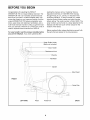
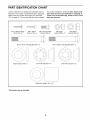
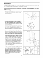
Model No. WLEL19020
Serial No.
USER'S MANUAL
Serial
Decal
/ii i
QUESTIONS?
If you have questions, or if
there are missing or damaged
parts, we will guarantee complete satisfaction through direct
assistance from our factory.
/
TO AVOID DELAYS, PLEASE
CALL DIRECT TO OUR TOLLFREE CUSTOMER HOT LINE.
The trained technicians on our
customer hot line will provide
immediate assistance, free of
charge.
CUSTOMER
,/
7
HOT LINE:
1-800-999-3756
Mon.-Fri.,
6 a.m.-6 p.m. MST
J
Patent Pending
CAUTION
Read all precautions and
instructions in this manual
before using this equipment.
Keep this manual for future
reference.
Visit our website at
www.weslo.com
new products, prizes,
fitness tips, and much more!
TABLE OF CONTENTS
IMPORTANT PRECAUTIONS
.............................................................
BEFORE YOU BEGIN ...................................................................
PART IDENTIFICATION CHART ...........................................................
ASSEMBLY ...........................................................................
HOW TO USE THE ELLIPTICAL ...........................................................
MAINTENANCE .......................................................................
CONDITIONING GUIDELINES ............................................................
PART LIST ...........................................................................
EXPLODED DRAWING .................................................................
HOW TO ORDER REPLACEMENT PARTS ...........................................
LIMITED WARRANTY
...........................................................
WESLO is a registered trademark of ICON Health & Fitness, Inc.
2
3
4
5
6
9
11
12
14
15
Back Cover
Back Cover
IM PORTANT PRECAUTIONS
WARNING:
To reduce the risk of serious injury, read the following
important precau-
tions before using the elliptical,
1, Read all instructions in this manual before
using the elliptical,
2. Use the elliptical only as described in this
manual.
3. It is the responsibility of the owner to
ensure that all users of the elliptical are adequately informed of all precautions,
,
Place the elliptical on a level surface, with a
mat beneath it to protect the floor or carpet,
Keep the elliptical indoors, away from moisture and dust.
5. Inspect and properly tighten all parts regularly. Replace any worn parts immediately.
6. Keep children under the age of 12 and pets
away from the elliptical at all times.
7. The elliptical should not be used by persons
weighing more than 250 pounds,
WARNI NG:
Wear appropriate clothing when using the
elliptical. Always wear athletic shoes for foot
protection.
9. When mounting and dismounting the elliptical, always hold the handlebars or the Thandle and step onto and off the pedal that
is in the lowest position.
10. Each time you stop exercising on the
elliptical, allow the pedals to come to
a complete stop before dismounting.
11. Always keep your back straight when using
the elliptical. Do not arch your back.
12. If you feel pain or dizziness at any time
while exercising, stop immediately and
begin cooling down.
13. The elliptical is intended for in-home use
only. Do not use the elliptical in a commercial, rental, or institutional setting.
Before beginning this or any exercise program, consult your physician.
This is especially important for persons over the age of 35 or persons with pre-existing health
problems. Read all instructions before using. ICON assumes no responsibility for personal injury
or property damage sustained by or through the use of this product.
BEFORE YOU BEGIN
Congratulations for selecting the WESLO ®
MOMENTUM 700 low-impact elliptical exerciser. The
MOMENTUM 700 is an incredibly smooth exerciser
that moves your feet in a natural elliptical path, minimizing the impact on your knees and ankles. And the
unique MOMENTUM 700 features adjustable resistance, upper-body and stationary handlebars, and a
multi-mode exercise monitor to help you get the most
from your exercise. Welcome to a whole new world of
natural, elliptical-motion exercise from WESLO.
For your benefit, read this manual carefully before
you use the elliptical. If you have questions after
reading the manual, call our Customer Service
Department toll-free at 1-800-999-3756, Monday
through Friday, 6 a.m. until 6 p.m. Mountain Time
(excluding holidays). To help us assist you, please
note the product model number and serial number
before calling. The model number is WLEL19020. The
serial number can be found on a decal attached to the
elliptical (see the front cover of this manual for the
location of the decal).
Before reading further, please familiarize yourself with
the parts that are labeled in the drawing below.
Water Bottle Holder
(Bottle not included)
Book Holder
Resistance Knob
T-Handle
/
Handlebar
®
Upright
Side Shield
FRONT
Disk
o
/
LEFT SIDE
Pedal
PedalArm
BACK
PART IDENTIFICATION
CHART
Use the chart below to identify the small parts used in
assembly. The number in parenthesis below each part
refers to the key number of the part, from the PART
LIST on page 14. The number after the dash indicates
M4 x 19mm Flange
Screw (9)--6
M4 x 16mm
Screw (16)4
the quantity needed for assembly. Note: Some small
parts may have been pre-attached for shipping. If
a part is not in the parts bag, check to see if it has
been pre-attached.
M6 x 16mm Button
Screw (54)_
M10 x 75mm Carriage Bolt (47)--2
Nylon Spacer (39)--2
M6 Nylon
Locknut (55)--2
M10 Nylon
Locknut (29)--6
M10 x 68mm Carriage Bolt (60)--2
3/4" Axle Cap (43)_*
Pedal Arm Spacer (41)--2*
* Extra parts may be included.
5
5/8" Axle Cap (57)--2*
ASSEMBLY
Assembly requires two people. Place all parts of the elliptical in a cleared area and remove the packing materials. Do not dispose of the packing materials until assembly is completed.
Assembly requires a phillips screwdriver
mallet r------"-_
.
(_,
two adjustable wrenches _
, and a rubber
"
Attach the Rear Stabilizer (33) to the Frame (1) with
two M10 x 75mm Carriage Bolts (47) and two M10
Nylon Locknuts (29).
29 "/"_," ",,_
_.-'>1
33
__47
.
Hold the Console Bracket (45) near the Upright (3)
and insert the Resistance Cable (26) down through
the Upright. Feed the Extension Wire (62) up through
the Console Bracket.
Attach the Console Bracket (45) to the Upright (3)
with two M6 x 16mm Button Screws (54) and two M6
Split Washers (38). Make sure not to pinch the
Resistance Cable (26) or the Extension Wire (62).
.
38 _&_,._._-----54
54C\
3\.
Making sure that the Reed Switch Wire (25) and the
Resistance Cable (58) are in the indicated slot in the
Frame (1), slide the Front Stabilizer (34) into the Frame.
Do not allow the Wire or the Cable to get pinched.
While a second person holds the Upright (3) near the
Frame (1), connect the Reed Switch Wire (25) to the
Extension Wire (62). Next, connect the Resistance
Cable (26) to the Lower Cable (58) in the following way:
_'_
• Refer to drawing A. Pull up on the metal bracket,
and insert the tip of the Resistance Cable (26) into
the wire clip on the Lower Cable (58) as shown.
62- _!
;I
34
F
• Refer to drawing B. Firmly pull the Resistance
Cable (26) and slide it into the metal bracket on the
Lower Cable (58) as shown.
• Refer to drawing C. Using pliers, squeeze the prongs
on the upper end of the metal bracket together.
Pull any slack Resistance Cable (26) out of the top of
the Upright (3). Attach the Upright to the Front
Stabilizer (34) with two M10 Nylon Locknuts (29).
Attach the Upright to the Frame (1) with two M10 x
68mm Carriage Bolts (60) and two M10 Nylon
Locknuts (29).
A t
B
i,i!/ 6.eta i
Bra cket_
58
i
//
.
While a second person holds the Console (6) near
the Console Bracket (45), connect the Extension Wire
(62) to the console wire. Make sure the slack
Resistance Cable (26) is pulled out of the Upright (3).
Attach the Console (6) to the Console Bracket (45)
with four M4 x 16mm Screws (16). Push the
Resistance Control Knob (50) onto the Resistance
Control (26).
Console
Wire
//,
16
.
Make sure that there are two Pivot Bushings (56) in
each Handlebar (8) and in the Upright (3).
Tap a 5/8" Axle Cap onto one end of the Pivot Axle
(2). Apply a thin film of the included grease to the
Pivot Axle.
57
Insert the Pivot Axle (2) through one of the Handlebars
(8) and the Upright (3).
2
56
.
Slide the other Handlebar (8) onto the Pivot Axle (2).
Secure the Handlebars to the Upright (3) by tapping a
5/8" Axle Cap (57) onto the end of the Pivot Axle.
57
7. AttachtheT-handle(10)to theUpright(3)withtwo
M6x 16mmButtonScrews(54)andtwo M6Nylon
Locknuts(55).
54
63
10
55
.
Make sure that there are four Pedal Arm Bushings
(11) in each Pedal Arm (12).
11
Identify the Left Pedal (31), which has an "L" molded
into its bottom surface. Attach the Left Pedal to one of
12
/
the Pedal Arms (12) using three M4 x 19mm Flange
Screws (9).
\
Attach the Right Pedal (not shown) in the same way.
.
9
Apply a thin film of grease to the left Handlebar (8)
and the Crank Arm (59)in the indicated locations.
Grease
59
Slide a Nylon Spacer (39) onto the Handlebar (8) and
a Pedal Arm Spacer (41) onto the Crank Arm (59).
Next, slide the Pedal Arm (12) with the Left Pedal
(31) onto the Handlebar and the Crank Arm. Secure
the Pedal Arm by tapping one 3/4" Axle Cap (43) onto
the Handlebar and another one onto the Crank Arm.
Attach the other Pedal Arm (not shown) to the right
side of the elliptical in the same way.
43
31
41
10. The Console (6) requires two "AA" batteries (not
included). Alkaline batteries are recommended.
10
To install batteries, first locate the battery clip under
the Console (6). Insert two batteries into the battery
clip as shown. Make sure that the batteries are
turned so the negative ends of the batteries
(marked "-') are touching the springs in the
battery clip.
@
Batteries
©
Battery
Clip--
11. Make sure that all parts of the elliptical are properly tightened. Place a mat under the elliptical to protect
the floor or carpet from damage.
HOW TO USE THE ELLIPTICAL
HOW TO EXERCISE ON THE ELLIPTICAL
HOW TO ADJUST THE RESISTANCE
PEDALS
To mount the elliptical, firmly hold the handlebars or
the T-handle and carefully step onto the pedal that is
in the lowest position. Next, step onto the other pedal.
Push the pedals until they begin to move with a continuous motion. Note: The pedal disks can turn in
either direction; it is recommended that you turn
the pedal disks in the direction shown below;
however, to give variety to your exercise, you may
choose to turn the pedal disks in the opposite
direction.
Pedal Disk
I
Pedal
To dismount the elliptical, allow the pedals to come to
a complete stop. CAUTION: The elliptical does not
have a freewheel; the pedals will continue to
move until the flywheel stops. When the pedals are
stationary, step off the highest pedal first. Then, step
off the lowest pedal.
As you exercise,
you can adjust
the resistance of
the pedals with
OF THE
Resistance Knob
/_-_
/
J
the resistance
F.--_- 9-
knob on the
console. To
_,
:_t_,
,W\_ ........ y/_ ......-_
increase the
resistance,
\
_y
turn the knob
_, _':', ',i'_J
clockwise; to
decrease the
resistance, turn the knob counterclockwise.
DESCRIPTION
OFTHECONSOLE
HOWTOOPERATE
THECONSOLE
Theconsoleis designedtohelpyougetthemost
fromyourworkouts.
Asyouexercise,youcanwatch
yourprogressaroundthe LEDtrack,whilethe
displayprovidescontinuous
exercisefeedback.
Thesix modesof thedisplayaredescribedbelow.
If there is a thin sheet of clear plastic on the face of
the console, remove it.
To turn on the power, press the on/reset button or
simply begin exercising. When the power is turned
on, one LED indicator will light in the LED track,
and the entire display will appear for two seconds.
The console will then be ready for operation.
000@000
2. Select one of the five modes:
o --
I
o
Scan mode-When the power
is turned on, the
scan mode will
automatically be
selected. One
mode indicator
will show that the
SCAN
CAL.
LAPS
TI --I.I I n--I
II'OO
SPe_D
TIME
DIST.
Mode Indicators
scan mode is selected, and a flashing mode indicator will show which mode is currently displayed.
Note: If a different mode is selected, you can
select the scan mode again by repeatedly pressing
the mode button.
Speed--This mode displays your current exercise
speed, in miles per hour.
Speed, time,
distance, laps,
or calorie mode-To select one of
these modes for
continuous
Time--This mode displays the length of time you
have exercised. Note: If you stop exercising, the time
mode will pause until you resume.
Distance--This mode displays the total distance you
have completed, in miles.
/
SCAN
CAL,
LAPS
i
13 1
t"7
SPffffD
TIMff
DIST.
display, press the
mode button repeatedly. The mode indicators will
show which mode is selected. (Make sure that the
scan mode is not selected.)
Laps--This mode displays the number of 1/4-mile
laps you have completed around the LED track.
The LED track represents a distance of 1/4 mile. As
you exercise, the indicators around the track will
light one at a time until you have completed 1/4
mile. A new lap will then begin.
Calorie--This mode displays the approximate number
of Calories you have burned.
Scan--This mode displays the speed, time, distance,
laps, and calorie modes, for 5 seconds each, in a
repeating cycle.
4. To reset the display, press the on/reset button.
To turn off the power, simply wait for about four
minutes. Note: The console has an "auto-off"
feature. If the pedals are not moved and the
console buttons are not pressed for four
minutes, the power will turn off automatically
in order to conserve the batteries.
BATTERY INSTALLATION
Before the console can be operated, two "AA" batteries must be installed. If you have not installed batteries, see assembly step 10 on page 8.
10
MAINTENANCE
CONSOLE TROUBLESHOOTING
Inspect and tighten all parts of the elliptical
regularly. Replace any worn parts immediately.
If the console does not function properly, the batteries
should be replaced. To replace the batteries, refer to
assembly step 10 on page 8.
The elliptical can be wiped clean with a soft cloth and
mild detergent. Do not use abrasives or solvents.
To prevent damage to the console, keep liquids away
from the console. Use only a sealable water bottle in
the console.
STORAGE
When storing the elliptical, remove the batteries from
the console. Keep the elliptical in a clean, dry location, away from moisture and dust.
11
CONDITIONING
GUIDELINES
The following guidelines will help you to plan your
exercise program. Remember that proper nutrition
and adequate rest are essential for successful results.
,WARN
gy. Only after the first few minutes of exercise does
your body begin to use stored fat calories for energy.
If your goal is to burn fat, adjust the intensity of your
exercise until your heart rate is near the smallest
number in your training zone as you exercise.
ING: Before
beginning this
For maximum fat burning, adjust the intensity of your
exercise until your heart rate is near the middle number in your training zone as you exercise.
or any exercise program, consult your physician, This is especially important for persons
over the age of 35 or persons with pre-existing health problems.
Aerobic Exercise
If your goal is to strengthen your cardiovascular system, your exercise must be "aerobic." Aerobic exercise is activity that requires large amounts of oxygen
for prolonged periods of time. This increases the
demand on the heart to pump blood to the muscles,
and on the lungs to oxygenate the blood. For aerobic
exercise, adjust the intensity of your exercise until
your heart rate is near the largest number in your
training zone.
EXERCISE INTENSITY
Whether your goal is to burn fat or to strengthen your
cardiovascular system, the key to achieving the
desired results is to exercise with the proper intensity.
The proper intensity level can be found by using your
heart rate as a guide. The chart below shows recommended heart rates for fat burning, maximum fat
burning, and cardiovascular (aerobic) exercise.
HOW TO MEASURE YOUR HEART RATE
HEART RATE TRAINING
To measure your
heart rate, first
exercise for at
least four minutes.
Then, stop exercising and place two
fingers on your
wrist as shown.
Take a six-second
heartbeat count, and multiply the result by 10 to find
your heart rate. For example, if your six-second heartbeat count is 14, your heart rate is 140 beats per
minute. (A six-second count is used because your
heart rate will drop rapidly when you stop exercising.)
ZONES
Mm _
]25
120
115
110
105
95
90
FatBum
BPM
145
138
130
125
118
110
103 MaxBurn
MAxV 165 155 145140 130 125 115 o;a ,o
AGE 20
30
40
50
60
70
80
To find the proper heart rate for you, first find your age
at the bottom of the chart (ages are rounded off to the
nearest ten years). Next, find the three numbers
above your age. The three numbers are your "training
zone." The smallest number is the recommended
WORKOUT
heart rate for fat burning; the middle number is the
heart rate for maximum fat burning; the largest
number is the heart rate for aerobic exercise.
GUIDELINES
Each workout should include the following three
important parts:
A warm-up, consisting of 5 to 10 minutes of stretching and light exercise. (See page 13.) A proper warmup increases your body temperature, heart rate, and
circulation in preparation for exercise.
Burning Fat
To burn fat effectively, you must exercise at a relatively low intensity level for a sustained period of time.
During the first few minutes of exercise, your body
uses easily accessible carbohydrate calories for ener-
12
EXERCISE FREQUENCY
Training zone exercise, consisting of 20 to 30
minutes of exercising with your heart rate in your
training zone. (During the first few weeks of your
exercise program, do not keep your heart rate in
your training zone for longer than 20 minutes.)
To maintain or improve your condition, plan three workouts each week, with at least one day of rest between
workouts. After a few months of regular exercise, you
may plan up to five workouts each week, if desired.
CAUTION: Make sure to progress at your own
pace and avoid overdoing it. Incorrect or excessive
training may result in injury to your health.
Remember, the key to success is make exercise a
regular and enjoyable part of your everyday life.
A cool-down, with 5 to 10 minutes of stretching.
This will increase the flexibility of your muscles
and will help to prevent post-exercise problems.
SUGGESTED
STRETCHES
The correct form for several basic stretches is shown at the
right. Move slowly as you stretch--never bounce.
1. Toe Touch Stretch
Stand with your knees bent slightly and slowly bend forward
from your hips. Allow your back and shoulders to relax as you
reach down toward your toes as far as possible. Hold for 15
counts, then relax. Repeat 3 times. Stretches: Hamstrings, back
of knees, and back.
2. Hamstring
Stretch
Sit with one leg extended. Bring the sole of the opposite foot
toward you and rest it against the inner thigh of your extended
leg. Reach toward your toes as far as possible. Hold for 15
counts, then relax. Repeat 3 times for each leg. Stretches:
Hamstrings, lower back, and groin.
3. Calf/Achilles
Stretch
With one leg in front of the other, reach forward and place your
hands against a wall. Keep your back leg straight and your back
foot flat on the floor. Bend your front leg, lean forward and move
your hips toward the wall. Hold for 15 counts, then relax.
Repeat 3 times for each leg. To cause further stretching of the
achilles tendons, bend your back leg as well. Stretches: Calves,
achilles tendons, and ankles.
4. Quadriceps Stretch
With one hand against a wall for balance,
one foot with your other hand. Bring your
buttocks as possible. Hold for 15 counts,
times for each leg. Stretches: Quadriceps
reach back and grasp
heel as close to your
then relax. Repeat 3
and hip muscles.
13
4
PART LIST--Model
Key
No.
Qty.
1
2
1
1
3
4
5
No. WLEL19020
R0802A
Key
No.
Qty.
Frame
Pivot Axle
36
37
2
2
Pulley Bearing
Pedal Disk
1
1
1
Upright
Right Side Shield
Left Side Shield
38
39
40
2
2
1
M6 Split Washer
Nylon Spacer
Side Shield Bracket
6
7
8
9
10
1
2
2
6
1
Console
Foam Handlebar Grip
Handlebar
M4 x 19mm Flange Screw
T-handle
41
42
43
44
45
2*
1
4*
1
1
Pedal Arm Spacer
Right Pedal
3/4" Axle Cap
M4 x 16mm Flat Screw
Console Bracket
11
12
13
14
15
16
8
2
10
1
1
11
Pedal Arm Bushing
Pedal Arm
M5 x 16mm Button Screw
Resistance Strap
Strap Buckle
M4 x 16mm Screw
46
47
48
49
50
51
2
2
1
1
1
4
Front Stabilizer Endcap
M10 x 75mm Carriage Bolt
Cable Clamp Assembly
M4 x 64mm Button Screw
Resistance Control Knob
M5 x 28mm Button Screw
17
18
19
20
21
22
23
24
25
26
27
28
29
30
31
2
2
2
2
1
2
1
1
1
1
2
1
6
1
1
M6 Nut
Adjustment Bracket
Eyebolt
M8 Nylon Jam Nut
Flywheel Axle
Flywheel Bearing
Flywheel
Magnet
Reed Switch/Wire
Resistance Control/Cable
Rear Stabilizer Endcap
Tension Spring
M10 Nylon Locknut
Belt
Left Pedal
52
53
54
55
56
57
58
59
60
61
62
63
64
65
#
1
2
4
2
6
2*
1
2
2
1
1
2
1
1
1
Return Spring
8.5 Washer
M6 x 16mm Button Screw
M6 Nylon Locknut
Pivot Bushing
5/8" Axle Cap
Lower Cable
Crank Arm
M10 x 68mm Carriage Bolt
Reed Switch Clamp
Extension Wire
T-handle Endcap
Plastic Washer
Crank Arm Plastic Spacer
Grease Packet
32
33
1
1
Pulley w/Shaft
Rear Stabilizer
#
#
1
2
User's Manual
Side Shield Decal
34
35
1
2
Front Stabilizer
5/16" Zinc Bolt
#
#
1
1
Warning Decal
Hardware Kit
Description
Description
Note: "#" indicates a non-illustrated part. "." indicates that an extra part may be included. Specifications are
subject to change without notice. See the back cover of this manual for information about ordering replacement
parts.
14
m
X
49
51
38
54
0
0
m
0
0
42
43
11
16
\
39
3
29
&
46
34
12
Z
46
11
37
36
0
r
m
r
0
0
64
11
11 41
%43
44
.-
27
29
32
47
9
12 43_11
o
00
o
i,.3
3>
HOW TO ORDER REPLACEMENT
PARTS
To order replacement parts, simply call our Customer Service Department toll-free at 1-800-999-3756, Monday
through Friday, 6 a.m. until 6 p.m. Mountain Time (excluding holidays). To help us assist you, please be prepared to give the following information when calling:
• The MODEL NUMBER of the product (WLEL19020)
• The NAME of the product (WESLO ® MOMENTUM
700 elliptical)
• The SERIAL NUMBER of the product (see the front cover of this manual)
• The KEY NUMBER and DESCRIPTION
of the part(s) from page 14 of this manual
LI MITED WARRANTY
ICON Health & Fitness, Inc. (ICON) warrants this product to be free from defects in workmanship and
material, under normal use and service conditions, for a period of ninety (90) days from the date of purchase. This warranty extends only to the original purchaser. ICON's obligation under this warranty is limited to replacing or repairing, at ICON's option, the product at one of its authorized service centers. All
products for which warranty claim is made must be received by ICON at one of its authorized service centers with all freight and other transportation charges prepaid, accompanied by sufficient proof of purchase.
All returns must be pre-authorized by ICON. This warranty does not extend to any product or damage to
a product caused by or attributable to freight damage, abuse, misuse, improper or abnormal usage or
repairs not provided by an ICON authorized service center, to products used for commercial or rental purposes, or to products used as store displays. No other warranty beyond that specifically set forth above
is authorized by ICON.
ICON is not responsible or liable for indirect, special or consequential damages arising out of or in connection with the use or performance of the product or damages with respect to any economic loss, loss
of property, loss of revenues or profits, loss of enjoyment or use, costs of removal, installation or other
consequential damages of whatsoever nature. Some states do not allow the exclusion or limitation of incidental or consequential damages. Accordingly, the above limitation may not apply to you.
The warranty extended hereunder is in lieu of any and all other warranties and any implied warranties of
merchantability or fitness for a particular purpose is limited in its scope and duration to the terms set forth
herein. Some states do not allow limitations on how long an implied warranty lasts. Accordingly, the above
limitation may not apply to you.
This warranty gives you specific legal rights. You may also have other rights which vary from state to state.
ICON HEALTH & FITNESS, INC., 1500 S. 1000 W., LOGAN, UT 84321-9813
Part No. 189444 R0802A
Printed in USA © 2002 ICON Health & Fitness, Inc.