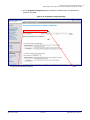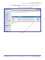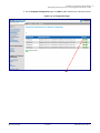
1
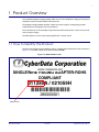
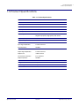
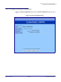
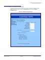
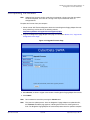
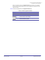
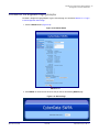
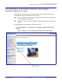
The IP Endpoint Company Singlewire Paging Adapter Operations Guide Part #011280 Document Part #930729A for Firmware Version 3.0.0 CyberData Corporation 3 Justin Court Monterey, CA 93940 (831) 373-2601 Singlewire Paging Adapter Operations Guide 930729A Part #011280 COPYRIGHT NOTICE: © 2013, CyberData Corporation, ALL RIGHTS RESERVED. This manual and related materials are the copyrighted property of CyberData Corporation. No part of this manual or related materials may be reproduced or transmitted, in any form or by any means (except for internal use by licensed customers), without prior express written permission of CyberData Corporation. This manual, and the products, software, firmware, and/or hardware described in this manual are the property of CyberData Corporation, provided under the terms of an agreement between CyberData Corporation and recipient of this manual, and their use is subject to that agreement and its terms. DISCLAIMER: Except as expressly and specifically stated in a written agreement executed by CyberData Corporation, CyberData Corporation makes no representation or warranty, express or implied, including any warranty or merchantability or fitness for any purpose, with respect to this manual or the products, software, firmware, and/or hardware described herein, and CyberData Corporation assumes no liability for damages or claims resulting from any use of this manual or such products, software, firmware, and/or hardware. CyberData Corporation reserves the right to make changes, without notice, to this manual and to any such product, software, firmware, and/or hardware. OPEN SOURCE STATEMENT: Certain software components included in CyberData products are subject to the GNU General Public License (GPL) and Lesser GNU General Public License (LGPL) “open source” or “free software” licenses. Some of this Open Source Software may be owned by third parties. Open Source Software is not subject to the terms and conditions of the CyberData COPYRIGHT NOTICE or software licenses. Your right to copy, modify, and distribute any Open Source Software is determined by the terms of the GPL, LGPL, or third party, according to who licenses that software. Software or firmware developed by Cyberdata that is unrelated to Open Source Software is copyrighted by CyberData, subject to the terms of CyberData licenses, and may not be copied, modified, reverse-engineered, or otherwise altered without explicit written permission from CyberData Corporation. TRADEMARK NOTICE: CyberData Corporation and the CyberData Corporation logos are trademarks of CyberData Corporation. Other product names, trademarks, and service marks may be the trademarks or registered trademarks of their respective owners. Technical Support The IP Endpoint Company The fastest way to get technical support for your VoIP product is to submit a VoIP Technical Support form at the following website: http://www.cyberdata.net/support/contactsupportvoip.php Phone: (831) 373-2601, Ext. 333 Email: [email protected] Fax: (831) 373-4193 Company and product information is at www.cyberdata.net. CyberData Corporation 930729A Operations Guide Revision Information Revision 930729A, which corresponds to firmware version 3.0.0, was released on September 24, 2013. Browsers Supported The following browsers have been tested against firmware version 3.0.0: Operations Guide • Internet Explorer (version: 10) • Firefox (also called Mozilla Firefox) (version: 22.0) • Chrome (version: 27.0.1453.116) • Safari (version: 6.0.5) 930729A CyberData Corporation Important Safety Instructions 1. Read these instructions. 2. Keep these instructions. 3. Heed all warnings. 4. Follow all instructions. 5. Do not use this apparatus near water. 6. Clean only with dry cloth. 7. Do not block any ventilation openings. Install in accordance with the manufacturer’s instructions. 8. Do not install near any heat sources such as radiators, heat registers, stoves, or other apparatus (including amplifiers) that produce heat. 9. Do not defeat the safety purpose of the polarized or grounding-type plug. A polarized plug has two blades with one wider than the other. A grounding type plug has two blades and a third grounding prong. The wide blade or the third prong are provided for your safety. If the provided plug does not fit into your outlet, consult an electrician for replacement of the obsolete outlet. 10. Protect the power cord from being walked on or pinched particularly at plugs, convenience receptacles, and the point where they exit from the apparatus. 11. Only use attachments/accessories specified by the manufacturer. 12. Refer all servicing to qualified service personnel. Servicing is required when the apparatus has been damaged in any way, such as power-supply cord or plug is damaged, liquid has been spilled or objects have fallen into the apparatus, the apparatus has been exposed to rain or moisture, does not operate normally, or has been dropped. 13. Prior to installation, consult local building and electrical code requirements. Warning Electrical Hazard: This product should be installed by a licensed electrician according to all local electrical and building codes. GENERAL ALERT Warning Electrical Hazard: To prevent injury, this apparatus must be securely attached to the floor/wall in accordance with the installation instructions. GENERAL ALERT CyberData Corporation 930729A Operations Guide Pictorial Alert Icons General Alert GENERAL ALERT This pictorial alert indicates a potentially hazardous situation. This alert will be followed by a hazard level heading and more specific information about the hazard. Ground This pictorial alert indicates the Earth grounding connection point. Hazard Levels Danger: Indicates an imminently hazardous situation which, if not avoided, will result in death or serious injury. This is limited to the most extreme situations. Warning: Indicates a potentially hazardous situation which, if not avoided, could result in death or serious injury. Caution: Indicates a potentially hazardous situation which, if not avoided, could result in minor or moderate injury. It may also alert users against unsafe practices. Notice: Indicates a statement of company policy (that is, a safety policy or protection of property). The safety guidelines for the equipment in this manual do not purport to address all the safety issues of the equipment. It is the responsibility of the user to establish appropriate safety, ergonomic, and health practices and determine the applicability of regulatory limitations prior to use. Potential safety hazards are identified in this manual through the use of words Danger, Warning, and Caution, the specific hazard type, and pictorial alert icons. CyberData Corporation 930729A Operations Guide Abbreviations and Terms Abbreviation or Term Definition A-law A standard companding algorithm, used in European digital communications systems to optimize, i.e., modify, the dynamic range of an analog signal for digitizing. AVP Audio Video Profile Cat 5 TIA/EIA-568-B Category 5 DHCP Dynamic Host Configuration Protocol LAN Local Area Network LED Light Emitting Diode Mbps Megabits per Second. NTP Network Time Protocol PBX Private Branch Exchange PoE Power over Ethernet (as per IEEE 802.3af standard) RTFM Reset Test Function Management SIP Session Initiated Protocol u-law A companding algorithm, primarily used in the digital telecommunication UC Unified Communications VoIP Voice over Internet Protocol CyberData Corporation 930729A Operations Guide i Contents Chapter 1 Product Overview 1 1.1 How to Identify This Product .....................................................................................................1 1.2 Product features .......................................................................................................................2 1.3 Product Specifications ..............................................................................................................3 1.4 Dimensions ...............................................................................................................................4 Chapter 2 Installing the Singlewire Paging Adapter 5 2.1 Parts List ..................................................................................................................................5 2.2 Installation ................................................................................................................................6 2.3 Connecting the Singlewire Paging Adapter ..............................................................................7 2.3.1 Connection Options ........................................................................................................7 2.3.2 Removable Connector ....................................................................................................8 2.3.3 Connect to the Power Source ........................................................................................9 2.3.4 Connect to the Network ...............................................................................................10 2.3.5 Confirm that the Singlewire Paging Adapter is Up and Running .................................11 2.3.6 Announcing the IP Address ..........................................................................................12 2.3.7 Restore the Factory Default Settings ...........................................................................13 2.4 Configure the Device Parameters ..........................................................................................14 2.4.1 Log in to the Configuration Home Page .......................................................................15 2.4.2 Configure the Device Parameters ................................................................................17 2.4.3 Configure the Network Parameters .............................................................................19 2.4.4 Updating the Firmware .................................................................................................22 2.4.5 Reboot the Singlewire Paging Adapter .........................................................................24 2.5 Identifying and Testing a Device when Using InformaCast 4.0 or Later .................................25 Appendix A Setting up a TFTP Server 31 A.1 In a LINUX Environment ........................................................................................................31 A.2 In a Windows Environment ...................................................................................................31 Appendix B Troubleshooting/Technical Support 32 B.1 Frequently Asked Questions (FAQ) ........................................................................................32 B.2 Documentation .......................................................................................................................32 B.3 Contact Information ................................................................................................................33 B.4 Warranty .................................................................................................................................34 B.4.1 Warranty & RMA Returns within the United States ......................................................34 B.4.2 Warranty & RMA Returns outside of the United States ...............................................34 B.4.3 Spare in the Air Policy ..................................................................................................35 B.4.4 Return and Restocking Policy ......................................................................................35 B.4.5 Warranty and RMA Returns Page ................................................................................35 Index Operations Guide 36 930729A CyberData Corporation 1 1 Product Overview The CyberData Singlewire Paging Adapter (SPA) is for use with Singlewire's paging and emergency notification software InformaCast® or InformaCast CK. The Singlewire Paging Adapter provides a direct connection to legacy analog paging systems enabling Informacast paging events to be broadcast. The on board relay can be controlled using InformaCast GPIO commands or can be set to activate when a page has begun. The SPA supports a Line-In input for playing MOH from a remote source 1.1 How to Identify This Product To identify the Singlewire Paging Adapter, look for a model number label similar to the one shown in Figure 1-1. The model number on the label should be 011280. Figure 1-1. Model Number Label WWW.CYBERDATA.NET SINGLEWIRE PAGING ADAPTER-ROHS COMPLIANT 011280A / 021059H 280000001 Model number Operations Guide 930729A CyberData Corporation Product Overview 2 Product features 1.2 Product features Operations Guide ● InformaCast ● 10k Ohm line out and 600 Ohm connectors for interfacing with analog amplifiers ● Audio Codecs • G.711 U-law • G.711 A-law • Singlewire's proprietary "high quality" audio format. ● 802.11Q VLAN support ● Web-based configuration and firmware upload ● PoE 802.3af enabled (Power-over-Ethernet) ● 19-inch rack mount option 930729A CyberData Corporation Product Overview 3 Product Specifications 1.3 Product Specifications Table 1-1. Product Specifications Specifications Protocol Informacast 4.0 or later Power Requirement PoE or 48V DC Ethernet I/F 10/100 Mbps Power Input PoE 802.3af or 48VDC Operating Temperature -10o C to 50o C (14o F to 122o F) Payload Types G711 Singlewire proprietary 'high quality' audio format Regulatory Compliance FCC Class A, UL 60950 Page Port Output Balanced 600 Ohm 10VPP Line In: Input Signal Amplitudes 2.0 VPP maximum Input Impedance 10k Ohm Line Out: Operations Guide Output Signal Amplitudes 2.0 VPP maximum Output Level +2dBm nominal Total Harmonic Distortion 0.5% maximum Output Impedance 10k Ohm Dimensions 6.11” L x 4.05” W x 1.15” H Weight 1.2 pounds Boxed Weight 1.8 pounds Part Number 011280 930729A CyberData Corporation Product Overview 4 Dimensions 1.4 Dimensions Figure 1-2 shows the dimensions for the Singlewire Paging Adapter. Figure 1-2. Dimensions 6.0 [152.4] 4.1 [104.0] 1.2 [29.6] Dimensions areare ininInches [Millimeters] Dimensions Inches [Millimeter] Operations Guide 930729A CyberData Corporation 5 2 Installing the Singlewire Paging Adapter 2.1 Parts List The packaging for the Singlewire Paging Adapter includes the parts in Table 2-2. Table 2-2. Parts List Quantity Operations Guide Part Name Illustration 1 Singlewire Paging Adapter 1 Installation Quick Reference Guide 1 Mounting Template (located on the last page of the Installation Quick Reference) 1 Mounting Kit (part #070057A) which includes: (2) #4-6 x 7/8" Mounting Anchors (2) #4 x 1-1/4" Round Phillips Wood Screws 930729A CyberData Corporation Installing the Singlewire Paging Adapter 6 Installation 2.2 Installation Figure 2-3 illustrates a typical configurations for the Singlewire Paging Adapter. Figure 2-3. Typical SPA Configuration (600 Ohm Output) InformaCast Server CD C Dp player layyerr Singlewire Paging g g g Adapter p 10k Ohm Line-In POE Switch 600 Ohm Page Port or 10k Ohm Line-Out IP Phone TPU-xxx Operations Guide 930729A CyberData Corporation Installing the Singlewire Paging Adapter 7 Connecting the Singlewire Paging Adapter 2.3 Connecting the Singlewire Paging Adapter Before you connect the Singlewire Paging Adapter, be sure that you have received all of the parts described in Section 2.1, "Parts List". 2.3.1 Connection Options See Figure 2-4 and Table 2-1 for the connection options that are available for the Singlewire Paging Adapter. Figure 2-4. Connection Options Line In Line Out Page Port Output Power Pin 1 Pin2 Pin 3 Pin 4 Pin 5 48VDC Pin 6 Pin 7 Table 2-1. Page Port Output Connections Pin Description 1 Unused 2 Unused 3 Positive 600-Ohm Audio Outputa. See Section 2.3.1.1, "Pin 3, 4, and 5—Positive/Negative 600Ohm Audio Output/Audio Ground Reference". 4 Negative 600-Ohm Audio Output.a. See Section 2.3.1.1, "Pin 3, 4, and 5—Positive/Negative 600Ohm Audio Output/Audio Ground Reference". 5 Audio Ground Reference. See Section 2.3.1.1, "Pin 3, 4, and 5—Positive/Negative 600-Ohm Audio Output/Audio Ground Reference". 6 Relay Contact - Commonb. See Section 2.3.1.2, "Pin 6 and 7—Relay Contact (Common/Normally Open)". 7 Relay Contact - Normally Openb. See Section 2.3.1.2, "Pin 6 and 7—Relay Contact (Common/Normally Open)". a. The 600-Ohm audio output of the page port is also suited for interfaces with lower input impedances. b. 1 Amp at 30 VDC for continuous loads Operations Guide 930729A CyberData Corporation Installing the Singlewire Paging Adapter 8 Connecting the Singlewire Paging Adapter 2.3.1.1 Pin 3, 4, and 5—Positive/Negative 600-Ohm Audio Output/Audio Ground Reference This output allows direct connection to paging amplifiers requiring a "Page Port" type input that meets a balanced 600 Ohm 10Vpp signal. 2.3.1.2 Pin 6 and 7—Relay Contact (Common/Normally Open) When enabled on the web interface (Section 2.4.2, "Configure the Device Parameters"), every time an audio file is played out of the local line-out or 600 Ohm output, the relay will close, thereby enabling amplifiers with a remote turn-on capability to become active. 2.3.2 Removable Connector Figure 2-5 shows the connector that is removable on the Singlewire Paging Adapter. Figure 2-5. Removable Connector Operations Guide 930729A CyberData Corporation Installing the Singlewire Paging Adapter 9 Connecting the Singlewire Paging Adapter 2.3.3 Connect to the Power Source To use PoE, plug a Cat 5 Ethernet cable from the Singlewire Paging Adapter Ethernet port to your network. As an alternative to PoE, you can plug one end of a +48V DC power supply into the SIP Paging Adapter, and plug the other end into a receptacle. If required, connect the earth grounding wire to the chassis ground on the back of the unit. See Figure 2-6. Figure 2-6. Connecting to the Power Source PoE To set up the Singlewire Paging Adapter, connect the device to your network: Poe • Non PoE with 48 VDC Power Supply For PoE, plug one end of an 802.3af Ethernet cable into the Singlewire Paging Adapter Ethernet port. Plug the other end of the Ethernet cable into your network. See the figure on the left. Non-Poe • Chassis Ground For Non-PoE, connect the Singlewire Paging Adapter to a 48VDC power supply. See the figure on the left. Chassis Ground • Chassis ground Operations Guide 930729A If required, connect the earth grounding wire to the Chassis Ground. See the figure on the left. CyberData Corporation Installing the Singlewire Paging Adapter 10 Connecting the Singlewire Paging Adapter 2.3.4 Connect to the Network Plug one end of a standard Ethernet cable into the SIP Paging Adapter Ethernet port. Plug the other end into your network. Figure 2-7. Connecting to the Network Operations Guide 930729A CyberData Corporation Installing the Singlewire Paging Adapter 11 Connecting the Singlewire Paging Adapter 2.3.5 Confirm that the Singlewire Paging Adapter is Up and Running The LEDs on the front of the Singlewire Paging Adapter verify the unit’s operations. Figure 2-8. SIP Paging Adapter LEDs Link (GREEN/AMBER LED) Activity (GREEN LED) Status (GREEN/BLUE LED) Paging (GREEN LED) 2.3.5.1 Confirm Power on, Network Connectivity, and Connection Speed When you plug in the Ethernet cable or power supply: • The GREEN/BLUE Status LED and the GREEN Paging LED both blink at a rate of 10 times per second during the initial network setup. • The round, GREEN/BLUE Status LED on the front of the Singlewire Paging Adapter comes on indicating that the power is on. Once the device has been initialized, this LED blinks at one second intervals. • The square, GREEN/AMBER Link LED above the Ethernet port indicates that the network connection has been established. The Link LED changes color to confirm the auto-negotiated connection speed: • • The Link LED is GREEN at 10 Mbps. • The Link LED is AMBER at 100 Mbps. The GREEN Paging LED comes on after the device is booted and initialized. This LED blinks when a page is in progress. You can disable Beep on Initialization on the Device Configuration page. 2.3.5.2 Verify Network Activity The square, GREEN Activity LED blinks when there is network traffic. Operations Guide 930729A CyberData Corporation Installing the Singlewire Paging Adapter 12 Connecting the Singlewire Paging Adapter 2.3.6 Announcing the IP Address To announce the IP address for the Singlewire Paging Adapter, briefly press and then quickly release the RTFM switch. See Figure 2-9. Note The IP address announcement can be heard if a speaker or amplified speaker is connected to the unit. Figure 2-9. RTFM Switch RTFM Switch Operations Guide 930729A CyberData Corporation Installing the Singlewire Paging Adapter 13 Connecting the Singlewire Paging Adapter 2.3.7 Restore the Factory Default Settings The Singlewire Paging Adapter is delivered with factory set default values for the parameters in Table 2-3. Use the RTFM switch (see Figure 2-10) on the back of the unit to restore these parameters to the factory default settings. Figure 2-10. RTFM Switch RTFM Switch Note When you perform this procedure, the factory default settings are restored. The default parameters for access are shown in Table 2-3. Table 2-3. Factory Default Settings Parameter Factory Default Setting IP Addressing DHCP IP Addressa 10.10.10.10 Web Access Username admin Web Access Password admin a Subnet Mask 255.0.0.0 Default Gatewaya 10.0.0.1 a. Default if there is not a DHCP server present. To restore these parameters to the factory default settings: 1. Press and hold the RTFM switch until the status and paging lights come on. 2. Continue to press the switch until after the indicator lights go off, and then release it. Note The “Restoring Defaults” announcement can be heard if a speaker or amplified speaker is connected to the unit. 3. The Singlewire Paging Adapter settings are restored to the factory defaults. Operations Guide 930729A CyberData Corporation Installing the Singlewire Paging Adapter 14 Configure the Device Parameters 2.4 Configure the Device Parameters To configure the device online, use a standard web browser. Configuration of the device is taken care of by the InformaCast server. If an InformaCast server can not be found, the device will return to factory defaults as shown in Table 2-4.. Table 2-4. Factory Default Settings Parameter Factory Default Setting IP Addressing DHCP a IP Address 10.10.10.10 Web Access Username admin Web Access Password admin a 255.0.0.0 Subnet Mask a 10.0.0.1 Default Gateway a. Default if there is not a DHCP server present. Operations Guide 930729A CyberData Corporation Installing the Singlewire Paging Adapter 15 Configure the Device Parameters 2.4.1 Log in to the Configuration Home Page 1. Open your browser to the Singlewire Paging Adapter IP address. This can be found within the InformaCast Server Test Menu. Note If the network does not have access to a DHCP server, the device will default to an IP address of 10.10.10.10. Note Make sure that the PC is on the same IP network as the Singlewire Paging Adapter. 2. When prompted, use the following default Web Access Username and Web Access Password to access the Home Page (Figure 2-11): Web Access Username: admin Web Access Password: admin Figure 2-11. Home Page Operations Guide 930729A CyberData Corporation Installing the Singlewire Paging Adapter 16 Configure the Device Parameters 3. On the Home Page, review the setup details and navigation buttons described in Table 2-5. Table 2-5. Home Page Overview Web Page Item Description Device Settings Change Username Type in this field to change the username (25 character limit). Change Password Type in this field to change the password (19 character limit). Re-enter Password Type the password again in this field to confirm the new password (19 character limit). Current Settings Serial Number Shows the device serial number. Mac Address Shows the device Mac address. Firmware Version Shows the current firmware version. IP Addressing Shows the current IP addressing setting (DHCP or Static). IP Address Shows the current IP address. Subnet Mask Shows the current subnet mask address. DNS Server 1 Shows the current DNS Server 1 address. DNS Server 2 Shows the current DNS Server 2 address. Boot Time Shows the boot time. Current Time Shows the current time. InformaCast Server Shows the InformaCast Server IP address. Configuration File Shows the configuration file. B’casts Accepted Shows the number of B’casts accepted. B’casts Rejected Shows the number of B’casts rejected. B’casts Active Shows the number of active B’casts. RTP Packets Rx’d Shows the number of RTP packets Rx’d. Import/Export Settings The user can export and edit the device's configuration (in XML format), and then reload it to a device (or devices) instead of making changes through the web interface. Press the Browse button to select a configuration file to import. Press the Import Configuration button to save a board configuration to the board. Note: The board will have to be reset before changes will take effect. Press the Export Configuration button to download the current board configuration. Click the Save button to save your configuration settings. Note: You need to reboot for changes to take effect. Click on the Reboot button to reboot the system. Operations Guide 930729A CyberData Corporation Installing the Singlewire Paging Adapter 17 Configure the Device Parameters 2.4.2 Configure the Device Parameters 1. Click on the Device Configuration button to open the Device Configuration page. See Figure 2-12. Figure 2-12. Device Configuration Page Operations Guide 930729A CyberData Corporation Installing the Singlewire Paging Adapter 18 Configure the Device Parameters 2. On the Device Configuration page, you may enter values for the parameters indicated in Table 2-6. Table 2-6. Device Configuration Parameters Web Page Item Description Miscellaneous Settings Beep on Initialization When selected, you will hear a beep when the device initializes. Enable line in to line out loopback When selected, audio is sent from the line -in to the line-out output. Enable relay on local audio When selected, the relay will be closed any time that audio is played out of the line-out/page port. This setting is for legacy analog amplifiers that are often connected to the page port. Analog amplifiers will often have a noticeable hum if they are turned on while there is no audio being played. The relay closure causes these amplifiers to turn on only when audio is sent to them. Click the Save button to save your configuration settings. Note: You need to reboot for changes to take effect. When the Test Audio button is pressed, you will hear a voice message for testing the device audio quality and volume. Click on the Test Relay button to do a relay test. Click on the Reboot button to reboot the system. 3. After changing the parameters, click the Save button. Operations Guide 930729A CyberData Corporation Installing the Singlewire Paging Adapter 19 Configure the Device Parameters 2.4.3 Configure the Network Parameters Configuring the network parameters enables your network to recognize the Singlewire Paging Adapter and communicate with it. Click on the Networking button to open the Network Configuration page. Figure 2-13. Network Configuration Page Operations Guide 930729A CyberData Corporation Installing the Singlewire Paging Adapter 20 Configure the Device Parameters On the Network Configuration page, enter values for the parameters indicated in Table 2-7. Table 2-7. Network Configuration Parameters Web Page Item Description Stored Network Settings Shows the settings stored in non-volatile memory. IP Addressing Select either DHCP IP Addressing or Static IP Addressing by marking the appropriate radio button. If you select Static, configure the remaining parameters indicated in Table 2-7. If you select DHCP, go to Step 3. IP Address Enter the Static IP address. Subnet Mask Enter the Subnet Mask address. Default Gateway Enter the Default Gateway address. DNS Server 1 Enter the DNS Server 1 address. DNS Server 2 Enter the DNS Server 2 address. VLAN ID (0-4095) Enter the VLAN ID number. Note: The device supports 802.11Q VLAN tagging support. The switch port connected to the device will need to be in “trunking mode” for the VLAN tags to propagate. VLAN Priority (0-7) Enter the VLAN priority number. DHCP Timeout DHCP Timeout in seconds Enter the desired timeout duration (in seconds) that the device will wait for a response from the DHCP server before defaulting back to the stored static IP address. Note: A value of -1 will cause the device to retry indefinitely and a value of 0 will cause the device to reset to a default of 60 seconds. Current Network Settings Shows the current network settings. IP Address Shows the current Static IP address. Subnet Mask Shows the current Subnet Mask address. Default Gateway Shows the current Default Gateway address. DNS Server 1 Shows the current DNS Server 1 address. DNS Server 2 Shows the current DNS Server 2 address. Click the Save button to save your configuration settings. Note: You need to reboot for changes to take effect. Click on the Reboot button to reboot the system. On this page: 1. Specify whether you use Static or DHCP IP Addressing by marking the appropriate radio button. Then, if you select Static, go to Step 2. 2. For Static IP Addressing, also enter values for the following parameters: • Operations Guide The Singlewire Paging Adapter’s IP Address: The Singlewire Paging Adapter is delivered with a factory default IP address. Change the default address to the correct IP address for your system. 930729A CyberData Corporation Installing the Singlewire Paging Adapter 21 Configure the Device Parameters • The Subnet Mask. • The Default Gateway. 3. Click Save when you are finished. 4. Click Reboot for the new settings to take effect. Operations Guide 930729A CyberData Corporation Installing the Singlewire Paging Adapter 22 Configure the Device Parameters 2.4.4 Updating the Firmware Note Updating from firmware versions earlier than 2.0.0 require a factory reset after the update has been completed. This is due to a change in the way that the device stores its configuration file. To update the firmware from your computer: 1. Please contact VoIP Technical Support to obtain the latest Singlewire Paging Adapter firmware file by submitting a contact form at the following website: http://www.cyberdata.net/support/contactsupportvoip.php 2. Log in to the Singlewire Paging Adapter home page as instructed in Section 2.4.1, "Log in to the Configuration Home Page". Figure 2-14. Upgrade Firmware Page 3. Select Browse, and then navigate to the location of the Singlewire Paging Adapter firmware file. 4. Click Submit. Operations Guide Note Do not reboot the board after pressing the Submit button. Note This starts the update process. Once the Singlewire Paging Adapter has updated the file, the Firmware countdown page appears, indicating that the firmware is being written to flash. The Singlewire Paging Adapter will automatically reboot when the upload is complete. 930729A CyberData Corporation Installing the Singlewire Paging Adapter 23 Configure the Device Parameters When the countdown finishes, the Upgrade Firmware page will refresh. The uploaded firmware filename should be displayed in the system configuration (indicating successful upload and reboot). Table 2-8 shows the web page items on the Upgrade Firmware page. Table 2-8. Firmware Upgrade Parameters Web Page Item Description File Upload Firmware Version Shows the current firmware version. Use the Browse button to navigate to the location of the firmware file that you want to upload. Click on the Submit button to automatically upload the selected firmware and reboot the system. Operations Guide 930729A CyberData Corporation Installing the Singlewire Paging Adapter 24 Configure the Device Parameters 2.4.5 Reboot the Singlewire Paging Adapter To reboot a Singlewire Paging Adapter, log in to the web page as instructed in Section 2.4.1, "Log in to the Configuration Home Page". 1. Click the Reboot button (Figure 2-15). Figure 2-15. Reboot Button Reboot button 2. Click Reboot. A normal restart will occur and you will see the following Reboot page. Figure 2-16. Reboot Page Operations Guide 930729A CyberData Corporation Installing the Singlewire Paging Adapter 25 Identifying and Testing a Device when Using InformaCast 4.0 or Later 2.5 Identifying and Testing a Device when Using InformaCast 4.0 or Later This section describes the basic process for identifying and testing the CyberData device when using Singlewire's InformaCast software version 4.0 or later. Note If you have questions or need help, please consult your InformaCast documentation and or contact the CyberData support team. Note CyberData's support is limited to IP endpoint functionality when used with an InformaCast system. To add the Singlewire Paging Adapter to the InformaCast server: 1. Click Edit IP Speakers on the Main Screen of the Singlewire Informacast Server Web Interface. Figure 2-17. Main Screen of the Singlewire InformaCast Server Web Interface Edit IP Speakers Operations Guide 930729A CyberData Corporation Installing the Singlewire Paging Adapter 26 Identifying and Testing a Device when Using InformaCast 4.0 or Later 2. On the IP Speaker Configuration page, InformaCast will indicate that it has detected new speakers. Click View. Figure 2-18. IP Speaker Configuration Page View InformaCast has detected new devices. Operations Guide 930729A CyberData Corporation Installing the Singlewire Paging Adapter 27 Identifying and Testing a Device when Using InformaCast 4.0 or Later 3. The IP Speaker Configuration page will show four newly detected speakers. Click Test. Figure 2-19. IP Speaker Configuration Page Test Operations Guide 930729A CyberData Corporation Installing the Singlewire Paging Adapter 28 Identifying and Testing a Device when Using InformaCast 4.0 or Later 4. On the Test IP Speaker page, Enter a number into the Test duration field. 5. Click Test. 6. You will hear a tone from the speaker being testing. 7. After the test, click Cancel to return to the IP Configuration page. Figure 2-20. Test IP Speaker Page Test duration View Speaker’s Status Page Note Cancel Test When viewing the device's status page via Informacast, Informacast links to the wrong port and path. Informacast expects our device's status page to be at: http://<ipaddr>:10004/status. The status page is actually at: http://<ipaddr>/ (port 80) Therefore, if a user clicks the link to view the status page and is directed to: http://10.10.10.10:1004/status The user will need to edit the url in the address bar to: http://10.10.10.10/ Operations Guide 930729A CyberData Corporation Installing the Singlewire Paging Adapter 29 Identifying and Testing a Device when Using InformaCast 4.0 or Later 8. On the IP Speaker Configuration page, Click Add to add a speaker to the InformaCast server. Figure 2-21. IP Configuration Page Add Operations Guide 930729A CyberData Corporation Installing the Singlewire Paging Adapter 30 Identifying and Testing a Device when Using InformaCast 4.0 or Later 9. On the Add IP Speaker page, Fill out appropriate fields and click Add. Figure 2-22. Add IP Speaker Page Add Your device is now registered to the InformaCast server. You now can configure this device as part of the InformaCast system setup as required. Operations Guide 930729A CyberData Corporation 31 Appendix A: Setting up a TFTP Server A.1 In a LINUX Environment To set up a TFTP server on LINUX: 1. Create a directory dedicated to the TFTP server, and move the files to be uploaded to that directory. 2. Run the following command where /tftpboot/ is the path to the directory you created in Step 1: the directory that contains the files to be uploaded. For example: in.tftpd -l -s /tftpboot/your_directory_name A.2 In a Windows Environment You can find several options online for setting up a Windows TFTP server. This example explains how to use the Solarwinds freeware TFTP server, which you can download at: http://www.cyberdata.net/support/voip/solarwinds.html To set up a TFTP server on Windows: 1. Install and start the software. 2. Select File/Configure/Security tab/Transmit Only. 3. Make a note of the default directory name, and then move the firmware files to be uploaded to that directory. Operations Guide 930729A CyberData Corporation 32 Appendix B: Troubleshooting/Technical Support B.1 Frequently Asked Questions (FAQ) To see a list of frequently asked questions, go to the following URL: http://www.cyberdata.net/products/voip/digitalanalog/singlewirepagingadapter/faqs.html B.2 Documentation The documentation for this product is released in an English language version only. You can download PDF copies of CyberData product documentation by going to the following URL: http://www.cyberdata.net/products/voip/digitalanalog/singlewirepagingadapter/docs.html Operations Guide 930729A CyberData Corporation 33 Contact Information B.3 Contact Information Contact CyberData Corporation 3 Justin Court Monterey, CA 93940 USA www.CyberData.net Phone: 800-CYBERDATA (800-292-3732) Fax: 831-373-4193 Sales Sales 831-373-2601 Extension 334 Technical Support The fastest way to get technical support for your VoIP product is to submit a VoIP Technical Support form at the following website: http://www.cyberdata.net/support/contactsupportvoip.php The Support Form initiates a ticket which CyberData uses for tracking customer requests. Most importantly, the Support Form tells us which PBX system and software version that you are using, the make and model of the switch, and other important information. This information is essential for troubleshooting. Please also include as much detail as possible in the Comments section of the Support Form. Phone: (831) 373-2601, Ext. 333 Email: [email protected] Returned Materials Authorization To return the product, contact the Returned Materials Authorization (RMA) department: Phone: 831-373-2601, Extension 136 Email: [email protected] When returning a product to CyberData, an approved CyberData RMA number must be printed on the outside of the original shipping package. Also, RMA numbers require an active VoIP Technical Support ticket number. A product will not be accepted for return without an approved RMA number. Send the product, in its original package, to the following address: CyberData Corporation 3 Justin Court Monterey, CA 93940 Attention: RMA "your RMA number" RMA Status Form If you need to inquire about the repair status of your product(s), please use the CyberData RMA Status form at the following web address: http://www.cyberdata.net/support/rmastatus.html Operations Guide 930729A CyberData Corporation 34 Warranty B.4 Warranty CyberData warrants its product against defects in material or workmanship for a period of two years from the date of purchase. Should the product fail Within Warranty, CyberData will repair or replace the product free of charge. This warranty includes all parts and labor. Should the product fail Out of the Warranty period, a flat rate repair charge of one half of the purchase price of the product will be assessed. Repairs that are Within Warranty period but are damaged by improper installation, modification, or abuse are deemed Out of Warranty and will be charged at the Out of Warranty rate. A device is deemed Out of Warranty when its purchase date is longer than two years or when the device has been damaged due to human error during installation, modification, or abuse. A replacement unit will be offered at full cost if the device cannot be repaired. End of Life Devices are included under this policy. End of Life devices are devices that are no longer produced or sold. Technical support is still available for these devices. However, no firmware revisions or updates will be provided. If an End of Life device cannot be repaired, the replacement offered may be the current version of the device. Products shipped to CyberData, both within and out of warranty, are shipped at the expense of the customer. CyberData will pay return shipping charges for repaired products. CyberData shall not under any circumstances be liable to any person for any special, incidental, indirect or consequential damages, including without limitation, damages resulting from use or malfunction of the products, loss of profits or revenues or costs of replacement goods, even if CyberData is informed in advance of the possibility of such damages. B.4.1 Warranty & RMA Returns within the United States If service is required, you must contact CyberData Technical Support prior to returning any products to CyberData. Our Technical Support staff will determine if your product should be returned to us for further inspection. If Technical Support determines that your product needs to be returned to CyberData, an RMA number will be issued to you at this point. Your issued RMA number must be printed on the outside of the shipping box. No product will be accepted for return without an approved RMA number. The product in its original package should be sent to the following address: CyberData Corporation 3 Justin Court. Monterey, CA 93940 Attn: RMA "xxxxxx" B.4.2 Warranty & RMA Returns outside of the United States If you purchased your equipment through an authorized international distributor or reseller, please contact them directly for product repairs. Operations Guide 930729A CyberData Corporation 35 Warranty B.4.3 Spare in the Air Policy CyberData now offers a Spare in the Air no wait policy for warranty returns within the United States and Canada. More information about the Spare in the Air policy is available at the following web address: http://www.cyberdata.net/support/warranty/spareintheair.html B.4.4 Return and Restocking Policy For our authorized distributors and resellers, please refer to your CyberData Service Agreement for information on our return guidelines and procedures. For End Users, please contact the company that you purchased your equipment from for their return policy. B.4.5 Warranty and RMA Returns Page The most recent warranty and RMA information is available at the CyberData Warranty and RMA Returns Page at the following web address: http://www.cyberdata.net/support/warranty/index.html Operations Guide 930729A CyberData Corporation 36 Index Symbols D +48V DC power supply 9 default gateway 13, 14 IP address 13, 14 subnet mask 13, 14 username and password 13, 14 web login username and password 15 default gateway 13, 14, 20 default gateway for static addressing 21 default login address 15 default settings, restoring 13 device configuration 7, 17 device configuration page 17 configurable parameters 16 device configuration parameters 18 device configuration password changing for web configuration access 17 DHCP addressing 20 DHCP IP addressing 20 dimensions 3, 4 DNS server 20 drivers 32 Numerics 100 Mbps indicator light 11 A activity light 11 address, configuration login 15 addressing DHCP 20 static 20 audio ground reference 8 audio output 8 C cat 5 ethernet cable 9 changing the web access password 17 Chrome (web browser) 3 configurable parameters 16, 18, 20 configuration device 7 using Web interface 14 configuration home page 15 configuration page configurable parameters 18, 20 connection options 7 connection speed 11 verifying 11 connections 7 connector (removable) 8 contact information 33 contact information for CyberData 33 Current Network Settings 20 current network settings 20 CyberData contact information 33 CyberData support limited to IP endpoint functionality 25 E ethernet port 9 export configuration button 16 export settings 16 F faqs 32 features 2 Firefox (web browser) 3 frequently asked questions (faqs) 32 H home page 15 I identifying the device (when using InformaCast 4.0) 25 Operations Guide 930729A CyberData Corporation 37 identifying your product 1 import configuration button 16 import settings 16 import/export settings 16 InformaCast Add IP Speaker Page 30 IP Speaker Configuration page 26 Test IP Speaker Page 28 testing and identifying a Singlewire-enabled device 25 Informacast linking to the wrong port and path 28 input specifications 3 installation 6 Internet Explorer (web browser) 3 IP address 13, 14, 20 IP addressing 20 default IP addressing setting 13, 14 L P page port 7 page port output connections 7 part number 3 parts list 5 password login 15 restoring the default 13, 14 pdf copies 32 port ethernet 9 power connecting to 9 requirement 3 product configuring 14 product overview 1 R line input specifications 3 line output specifications 3 line-in 7 line-out 7 link light 11 Linux, setting up a TFTP server on 31 log in address 15 reboot 24 regulatory compliance 3 relay 8 relay contact 8 restoring factory default settings 13 return and restocking policy 35 RMA returned materials authorization 33 RMA status 33 M S Mozilla Firefor (web browser) 3 Safari (web browser) 3 sales 33 service 33 Singlewire Informacast Server Web Interface 25 Singlewire-enabled device how to identify 1 installation 6 Spare in the Air Policy 35 static addressing 20 static IP addressing 20 status light 11 Stored Network Settings 20 subnet mask 13, 14, 20 subnet mask static addressing 21 N network activity, verifying 11 network configuration page 19 network parameters, configuring 19 network setup button 19 network, connecting to 10 O orange link light 11 output specifications 3 overview 1 T tech support 33 Operations Guide 930729A CyberData Corporation 38 technical support 32 technical support, contact information 33 testing the device (when using InformaCast 4.0) 25 typical system installation 6 U username changing for web configuration access 17 default for web configuration access 15 restoring the default 13, 14 utilities 32 V verifying connection speed 11 network activity 11 network connectivity 11 VLAN ID 20 VLAN Priority 20 VLAN tagging support 20 VLAN tags 20 W warranty 34 warranty & RMA returns outside of the United States 34 warranty and RMA returns page 35 warranty policy at CyberData 34 web access password 13, 14 web access username 13, 14 web configuration log in address 15 web-based configuration 14 weight 3 Windows, setting up a TFTP server on 31 Operations Guide 930729A CyberData Corporation