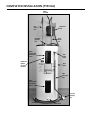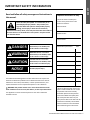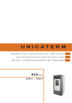
1
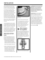
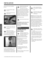
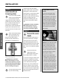
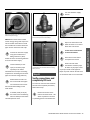
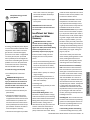
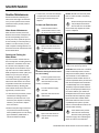
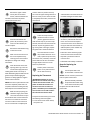
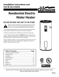
Installa on Instruc ons and
Use & Care Guide
Residential Electric
Water Heater
DO NOT RETURN THIS UNIT TO THE STORE
Read this manual and the labels on the water heater before you install,
operate, or service it. If you have difficulty following the direc ons, or
aren’t sure you can safely and properly do any of this work yourself:
• Call your Lowe’s® store to have this water heater installed. Lowe’s® Professional
Installa on is available for this product and the work is guaranteed.
• Schedule an appointment with a qualified person to install your water heater.
• Call our Technical Assistance Hotline at 1-877-817-6750. We can help you with installa on, opera ons, troubleshoo ng, or maintenance. Before you call, write down
the model and serial number from the water heater’s data plate.
Incorrect installa on, opera on, or service can damage the water heater, your house
and other property, and present risks including fire, scalding, electric shock, and
explosion, causing serious injury or death.
Table of Contents................................... Page
Important Safety Informa on ............................................... 3
Ge ng Started ....................................................................... 6
Installa on .............................................................................. 7
Troubleshoo ng ................................................................... 17
Maintenance ........................................................................ 21
Safety Labels ......................................................................... 25
Diagrams............................................................................... 27
Repair Parts .......................................................................... 28
LOW LEAD
CONTENT
Keep this manual in the pocket on heater for future reference whenever maintenance, adjustment or service is required.
Retain your original receipt as proof of purchase.
323099-000
March 2012
COMPLETED INSTALLATION TYPICAL
Water
shut off
Hot
water
line
Electrical
junc on
box
Expansion
tank
Cold
water
line
Upper
Element and
Thermostat
access
T&P
relief
valve
ECO Reset
Bu on
(on most
models)
Data
plate
T&P
discharge
pipe
Lower
Element and
Thermostat
access
Drain pan
discharge
pipe
Drain pan
Drain valve
Read and follow all safety messages and instruc ons in
this manual.
This is the safety alert symbol. It is used to alert you to
poten al physical injury hazards. Obey all safety messages that follow this symbol to avoid possible property
damage, serious injury or death. Do not remove any
permanent instruc ons, labels, or the data plate from either the outside of
the water heater or on the inside of the access panels. Keep this manual
near the water heater.
Important informa on to keep
Fill out this sec on and keep this
manual in the pocket of the water
heater for reference.
Date Puchased:
Model number:
Serial number:
DANGER
DANGER indicates hazardous
situa on that, if not avoided, will
result in death or serious injury.
WARNING
WARNING indicates a hazardous
situa on that, if not avoided, could
result in death or serious injury.
CAUTION
CAUTION indicates a hazardous
situa on that, if not avoided, could
result in minor or moderate injury.
NOTICE
Maintenance performed:*
Date:
NOTICE indicates prac ces not
related to physical injury.
The California Safe Drinking Water and Toxic Enforcement Act requires the
Governor of California to publish a list of substances known to the State of
California to cause cancer, birth defects, or other reproductive harm, and
requires businesses to warn of potential exposure to such substances.
WARNING! This product contains one or more chemicals known to the
State of California to cause cancer, birth defects, or other reproductive harm.
This appliance can cause low-level exposure to some of the substances
included in the act.
*Drain and flush tank and remove and
inspect anode rod a er first six months
of opera on and at least annually
therea er. Operate the Temperature
and Pressure Relief Valve (T&P) annually and inspect T&P valve every 2-4
years (see the label on the T&P valve for
maintenance schedule). See the Maintenance sec on for more informa on
about maintaining this water heater.
Residen al Electric Water Heater Use and Care Guide • 3
SAFETY
IMPORTANT SAFETY INFORMATION
SAFETY
IMPORTANT SAFETY INFORMATION
T
o reduce the risk of property
damage, serious injury or death,
read and follow the precau ons below,
all labels on the water heater, and
the safety messages and instruc ons
throughout this manual.
RISKS DURING INSTALLATION
AND MAINTENANCE
Electric Shock Risk
Contact with the electrical
parts in the junc on box
and behind the access
doors can result in severe injury or
death from electrical shock:
• Disconnect power by opening the
circuit breaker or removing the fuses
before installing or servicing.
• Use a non-contact circuit tester to
confirm that power is off before
working on or near any electrical
parts.
• Replace the junc on box cover and
access doors a er servicing.
Li ing Risk
WARNING! The
water heater is heavy.
Follow these precauons to reduce the risk of property
damage, injuries from li ing or impact
injuries from dropping the water
heater.
• Use at least two people to li the
water heater.
• Be sure you both have a good grip
before li ing.
• Use an appliance dolly or hand truck
to move the water heater.
RISKS DURING OPERATION
Scalding Risk
This water heater
can make water hot
enough to cause
severe burns instantly, resul ng in
severe injury or death.
• Feel water before bathing or
showering
• To reduce the risk of scalding, install
Thermosta c Mixing Valves (temperature limi ng valves) at each pointof-use. These valves automa cally
mix hot and cold water to limit the
temperature at the tap. Mixing valves
are available from Lowe’s®. Follow
manufacturer’s instruc ons for installa on and adjustment of the valves.
• The thermostat(s) on this water
heater have been factory set to
approximately 120°F to reduce the
risk of scalding. Higher temperatures
increase the risk of scalding, but
even at 120°F, hot water can scald.
If you choose a higher temperature,
Thermosta c Mixing Valves located
at each point-of-use are par cularly
important to help avoid scalding.
Temperature
Time to Produce
a Serious Burn
120°F (49°C)
More than 5 minutes
125°F (52°C)
1½ to 2 minutes
130°F (54°C)
About 30 seconds
135°F (57°C)
About 10 seconds
140°F (60°C)
Less than 5 seconds
145°F (63°C)
Less than 3 seconds
150°F (66°C)
About 1½ seconds
155°F (68°C)
About 1 second
4 • Residen al Electric Water Heater Use and Care Guide
For informa on about changing the
factory thermostat se ng(s), refer to
the “Adjus ng Temperature” sec on in
this manual (see page 15, step 10).
Even if you set the water heater
thermostat(s) to a low se ng, higher
temperatures may occur in certain
circumstances:
• In some cases, repeated small draws
of water can cause the hot and cold
water in the tank to “stack” in layers. If this happens, the water can
be as much as thirty degrees ho er
than the thermostat se ng. This
temperature varia on is the result
of your usage pa ern and is not a
malfunc on.
• Water temperature will be ho er if
someone adjusted the thermostat(s)
to a higher se ng.
• Problems with the thermostat(s),
or other malfunc ons may result in
higher than expected water temperatures.
• If the water heater is in a hot environment, the water in the tank can
become as hot as the surrounding air,
regardless of the thermostat se ng.
• If the water supplied to the water
heater is pre-heated (for example,
by a solar system) the temperature
in the tank may be higher than the
water heater’s thermostat se ng.
To reduce the risk of unusually hot
water reaching the fixtures in the
house, install Thermosta c Mixing
Valves at each point-of-use.
If anyone in your home is at par cular
risk of scalding (for example, the elderly, children, or people with disabili es)
or if there is a local code or state law
According to a na onal standard
American Society of San ary Engineering (ASSE 1070) and most local plumbing
codes, the water heater’s thermostat
should not be used as the sole means to
regulate water temperature and avoid
scalds.
Properly adjusted Thermosta c Mixing
Valves installed at each point-of-use allow you to set the tank temperature to
a higher se ng without increasing risk
of scalds. A higher temperature se ng
allows the tank to provide much more
hot water and can help provide proper
water temperatures for appliances such
as dishwashers and washing machines.
Higher tank temperatures (140°F)
also kill bacteria that cause a condion known as “smelly water” and can
reduce the levels of bacteria that cause
water-borne diseases.
Water Contamina on Risk
Do not use chemicals that could contaminate the potable water supply. Do
not use piping that has been treated
with chromates, boiler seal, or other
chemicals.
Fire Risk
To reduce the risk of a
fire that could destroy
your home and seriously
injure or kill people:
• Do not store things that can burn
easily such as paper or clothes next to
the water heater.
• Be sure the junc on box cover and
the access door covers are in place.
These covers keep debris from entering and poten ally being ignited,
and help keep any internal fires from
spreading.
• Keep the water heater from becoming wet. Immediately shut the water
heater off and have it inspected by a
qualified person if you find that the
wiring, thermostat(s) or surrounding
insula on have been exposed to water in any way (e.g., leaks from plumbing, leaks from the water heater
itself can damage property and could
cause a fire risk). If the water heater
is subjected to flood condi ons or the
thermostat(s) have been submerged
in water, the en re water heater must
be replaced.
• Make electrical connec ons properly,
according to the instruc ons on page
14. Use 10 gauge solid copper wire.
Use a UL listed or CSA approved strain
relief. Connect ground wire to green
ground screw.
Explosion Risk
High temperatures and
pressures in the water
heater tank can cause an
explosion resul ng in property damage,
serious injury or death. A new Temperature and Pressure (T&P) Relief
Valve is included with your water heater
to reduce risk of explosion by discharging hot water. Addi onal temperature
and pressure protec ve equipment may
be required by local codes.
Maintain the T&P Relief Valve properly.
Follow the maintenance instruc ons
provided by the manufacturer of the
T&P Relief Valve (label a ached to T&P
Relief Valve) and the procedure that
starts on page 24.
An explosion could occur if the T&P Relief Valve or discharge pipe is blocked.
Do not cap or plug the T&P Relief Valve
or discharge pipe.
Fire and Explosion Risk if Hot Water is
Not Used for Two Weeks or More
CAUTION! Hydrogen gas builds up
in a hot water system when it is not
used for a long period (two weeks or
more). Hydrogen gas is extremely
flammable. If the hot water system has
not been used for two weeks or more,
open a hot water faucet for several
minutes at the kitchen sink before
using any electrical appliances connected to the hot water system. Do
not smoke or have an open flame or
other igni on source near the faucet
while it is open. ■
A na onally recognized tes ng laboratory maintains periodic inspec on
of the valve produc on process and
cer fies that it meets the requirements
for Relief Valves for Hot Water Supply
Systems, ANSI Z21.22. The T&P Relief
Valve’s relief pressure must not exceed
the working pressure ra ng of the water heater as stated on the ra ng plate.
Residen al Electric Water Heater Use and Care Guide • 5
SAFETY
requiring a certain water temperature
at the hot water tap, then these precauons are par cularly important.
GETTING STARTED
Review all of the instruc ons
before you begin work.
If you aren’t sure that you
can safely and properly do this work
yourself, call your Lowe’s® store to
arrange for Professional Installa on
(you may also call a qualified person
of your choice, such as a licensed
plumber or electrician, to have the
work done). Improper installa on can
damage the water heater, your home
and other property, and can present
risks of serious injury or death.
GETTING STARTED
1
Figure 1 - Flexible connectors use compression
fi ngs and do not require soldering.
Figure 2 - Use a non-contact circuit tester to
insure that the power is off before you work on
a circuit.
Figure 3 - Install a Pressure Reducing Valve set to
50 to 60 PSI.
Check with your local and
state authori es for any local
or state codes that apply to
your area. In the absence of local and
state codes, follow Na onal Fire
Protec on Associa on (NFPA-70) and
the current edi ons of the Na onal
Electric Code (NEC) and the Internaonal Plumbing Code (IPC). The
instruc ons in this manual comply with
na onal codes, but the installer is
responsible for complying with local
codes.
2
Massachuse s code requires this water heater to be installed in accordance
with Massachuse s 248-CMR 2.00 and
248-CMR 5.00: State Plumbing Code.
Other local and state authori es may
have similar requirements or other
codes applicable to the installa on of
this water heater.
3
Before you start, be sure you
have, and know how to use, the
following tools and supplies:
• Plumbing tools and supplies appropriate
for the type of water pipes in your home
• Threaded connectors (figure 1) for
the cold and hot water pipes
• For homes plumbed with plas c
pipe, use threaded connectors
6 • Residen al Electric Water Heater Use and Care Guide
suitable for the specific type of
plas c pipe used: CPVC and PEX
(cross-linked polyethylene). Do
not use PVC pipe.
• For homes with copper pipes,
you may purchase connector kits
with compression fi ngs that
don’t require soldering (figure 1).
Compression fi ngs are easier
to install than soldering copper
pipes.
• Teflon® tape or pipe joint compound
approved for potable water
• Tools to make the electrical connecons (for example, screwdrivers, wire
strippers)
• Non-Contact circuit tester to check
for power (figure 2)
• Water Pressure Gauge (see next
page, figure 4)
Recommended Accessories:
• Suitable drain pan (see page 8, figure 6)
• Automa c leak detec on and shutoff device
• Pressure Reducing Valve (figure 3)
• Thermal Expansion Tank (see next
page, figure 5)
• Point-of-use Thermosta c Mixing
Valves (see page 8, figure 7) ■
INSTALLATION
✓
Water pressure
increase caused by
thermal expansion
Step 1:
✓
Verify that your
home is equipped
and up-to-date for
proper opera on
Installing a new water heater is the
perfect me to examine your home’s
plumbing system and make sure the
system is up to current code standards.
There have likely been plumbing code
changes since the old water heater
was installed. We recommend installing the following accessories and any
other needed changes to bring your
home up to the latest code requirements.
Use the checklist below and inspect
your home. Install any devices you need
to comply with codes and assure that
your new water heater performs at its
best. Check with your local plumbing
official for more informa on.
✓
Water pressure
We recommend checking your
home’s water pressure with a pressure
gauge (figure 4). Most codes allow a
maximum incoming water pressure of
80 psi. We recommend a working pressure no higher than 50-60 psi.
HOW: Purchase an inexpensive water
pressure gauge from Lowe’s®. Connect
the Water Pressure Gauge to an outside faucet and measure the maximum
water pressure experienced throughout the day (highest water pressures
Figure 4 - Use a Water Pressure Gauge to make
sure your home’s water pressure is not too high.
o en occur at night).
Verify that you have a properly sized
Thermal Expansion Tank (figure 5). We
recommend installing an expansion
tank if your home does not have one.
Codes require a properly pressurized,
properly sized Thermal Expansion Tank
in almost all homes. (See photo on
inside front cover.)
To limit your home’s water pressure:
Locate your home’s Pressure Reducing Valve (PRV) on the main incoming
(cold) water supply line and adjust the
water pressure control to between 50
and 60 psi. If your home does not have
a Pressure Reducing Valve, install a
PRV on the home’s main water supply
line and set it to between 50 and 60
psi. Pressure Reducing Valves are available at Lowe’s®.
BACKGROUND: Over the years, many
u li es have increased water supply pressures so they can serve more
homes. In some homes today, pressures exceed 100 psi. High water
pressures can damage water heaters,
causing premature leaks. If you have
replaced toilet valves, had a water
heater leak, or had to repair appliances connected to the plumbing system,
pay par cular a en on to your home’s
water pressure. When purshasing a
PRV, make sure the PRV has a built-in
bypass.
Figure 5 - A Thermal Expansion Tank helps
protect the home’s plumbing system from pressure spikes.
HOW: Connect the Thermal Expansion
Tank (available from Lowe’s®) to the
cold water supply line near the water
heater. The expansion tank contains
a bladder and an air charge. To work
properly, the Thermal Expansion Tank
must be sized according to the water
heater’s tank capacity and pressurized
to match the home’s incoming water
pressure. Refer to the installa on
instruc ons provided with the Thermal
Expansion Tank for installa on details.
BACKGROUND: Water expands when
heated, and the increased volume
of water must have a place to go, or
Residen al Electric Water Heater Use and Care Guide • 7
INSTALLATION
F
ollow these steps for proper
installa on:
INSTALLATION
INSTALLATION
thermal expansion will cause large
increases in water pressure (despite
the use of a Pressure Reducing Valve
on the home’s main water supply
line). The Safe Drinking Water Act of
1974 requires the use of backflow
preventers and check valves to restrict
water from your home reentering
the public water system. Backflow
preventers are o en installed in water
meters and may not be readily visible.
As a result, most all plumbing systems
today are now “closed,” and almost all
homes now need a Thermal Expansion Tank.
A Thermal Expansion Tank is a prac cal and inexpensive way to help avoid
damage to the water heater, washing
machine, dishwasher, ice maker and
even toilet valves. If your toilet occasionally runs for no apparent reason
(usually briefly at night), that may be
due to thermal expansion increasing
the water pressure temporarily.
Water pipe and tank
leaks
Leaks from plumbing pipes or from
the water heater itself can damage
property and could cause a fire risk.
• Install an automa c leak detec on
and shutoff device (available from
Lowe’s®). These devices can detect
water leaks and can shut off the water
heater’s water supply if a leak occurs.
• Install a suitable drain pan (available
from Lowe’s®) under the water heater (figure 6) to catch condensa on
or leaks in the piping connec ons
or tank. Most codes require and
we recommend installing the water
WARNING! Even if the water heater
thermostat is set to a rela vely low
temperature, hot water can scald.
Install Thermosta c Mixing Valves at
each point-of-use to reduce the risk of
scalding (see page 4).
Figure 6 - A suitable drain pan piped to an
adequate drain can help protect flooring from
leaks and drips.
heater in a drain pan that is piped
to an adequate drain. The drain pan
must be at least two inches wider
than the diameter of the water
heater. Install the drain pan so the
water level would be limited to a
maximum depth of 1-3/4”.
✓
Water temperature regula on
Install Thermosta c Mixing Valves (figure 7) to regulate the temperature of
the water supplied to each point-ofuse (for example, kitchen sink, bathroom sink, bath, shower). Consult the
valve manufacturer’s instruc ons or a
qualified person.
Figure 7 - Thermosta c Mixing Valves installed
at each point-of-use can help prevent scalding.
8 • Residen al Electric Water Heater Use and Care Guide
BACKGROUND: A Thermosta c Mixing Valve, installed at each pointof-use, mixes hot water from the
water heater with cold water to more
precisely regulate the temperature of
hot water supplied to fixtures. If you
aren’t sure if your plumbing system
is equipped with properly installed
and adjusted Thermosta c Mixing
Valves at each point where hot water
is used, contact a qualified person for
more informa on. ■
5
The loca on is not prone to
physical damage by vehicles,
flooding, or other risks.
Before installing your water heater,
ensure that:
The water heater will be:
• Installed indoors close to
the center of the plumbing
system.
• In a suitable drain pan piped to an
adequate floor drain or external to
the building (See page 8, figure 6).
• In an area that will not freeze
• In an area that is suitable for installing the water heater ver cally
2
The loca on has adequate
space (clearances) for periodic
servicing.
3
The floor can support the
weight of a full water heater.
Your area is not prone to
earthquakes. If it is, use
special straps as required by
local building codes.
4
NOTICE: The state of California requires bracing, anchoring, or strapping
the water heater to avoid its moving
during an earthquake. Contact local
u li es for code requirements in your
area, visit h p://www.dsa.dgs.ca.gov,
or call 1-916-445-8100 and request
instruc ons. Other loca ons may have
similar requirements. Check with your
local and state authori es.
Drain
Pan
Drain
In a garage, install a vehicle stop to avoid water
heater damage.
Avoid loca ons such as a cs,
upper floors, or where a leak
might damage the structure
or furnishings. Due to the normal
corrosive ac on of water, the tank will
eventually leak. To minimize property
damage from leaks, inspect and
maintain your water heater in accordance with this manual’s instruc ons.
Install a suitable drain pan under the
water heater piped to an adequate
drain. Inspect the drain pan, pipes, and
surrounding area regularly and fix any
leaks found. Drain pans are available
from Lowe’s®. Leaks are frequently in
the plumbing system itself and not the
water heater.
6
Step 3:
On the old water heater,
remove the electrical
junction box access panel.
Using a non-contact circuit tester,
check the wiring to make certain the
power is OFF.
WARNING! Working on an energized circuit can result in severe injury
or death from electrical shock.
4
Disconnect the electrical
wires.
Open a hot water faucet and
let the hot water run un l it is
cool (This may take 10
minutes or longer).
5
Let the hot water run un l it is cool.
Removing the old water
heater
Read each installa on step
and decide if you have the
necessary skills to install the
water heater. Only proceed if you can
safely perform the work. If you are not
comfortable, have a qualified person
perform the installa on.
1
Locate the water heater’s
circuit breaker and turn it OFF
(or remove the circuit’s
fuses).
3
Vehicle
Stop
1
2
WARNING! Be sure the water runs
cool before draining the tank to reduce
the risk of scalding.
Connect a garden hose to the
drain valve and place the
other end of the hose in a
drain, outside, or a bucket. (Note that
sediment in the bo om of the tank
may clog the valve and prevent it
from draining. If you can’t get the
6
Residen al Electric Water Heater Use and Care Guide • 9
INSTALLATION
Step 2:
Verify that the loca on
is appropriate
INSTALLATION
tank to drain, contact a qualified
person.)
7
Turn the cold water supply
valve OFF.
8
Open the drain valve on the
water heater.
Disconnect the water pipes.
Many water pipes are
connected by a threaded
union which can be disconnected with
wrenches. If you must cut the water
pipes, cut the pipes close to the water
heater’s inlet and outlet connec ons,
leaving the water pipes as long as
possible. If necessary, you can make
them shorter later when you install
the new water heater.
11
12
INSTALLATION
Draining the old water heater.
9
Also open a hot water faucet
to help the water in the tank
drain faster.
When the tank is empty,
disconnect the Temperature &
Pressure (T&P) Relief Valve
discharge pipe. You may be able to
reuse the discharge pipe, but do not
10
Removing the T&P Relief Valve discharge pipe.
reuse the old T&P Relief Valve. A new
T&P Relief Valve comes installed on
your water heater (or on some models,
is in the carton with the water heater).
Remove the old water heater.
WARNING! Use two or more people
to remove or install water heater.
Failure to do so can result in back or
other injury.
2
Install a suitable drain pan
that is piped to an adequate
drain.
3
Set the water heater in place
taking care not to damage
the drain pan.
NOTICE: Most codes require se ng
the water heater in a suitable drain
pan piped to an adequate drain. The
drain pan helps avoid property damage which may occur from condensaon or leaks in the piping connec ons
or tank. The drain pan must be at
least two inches wider than the diameter of the water heater. Install the
drain pan so the water level is limited
to a maximum depth of 1-3/4”.
Step 4:
Installing the new
water heater
Completely read all instrucons before beginning. If you
are not sure you can complete the installa on, DO NOT
RETURN THIS UNIT TO THE STORE.
Seek assistance from any of the
following sources:
• Lowe’s® Professional Installa on
is available for this product and
the work is guaranteed. Call your
Lowe’s® store to have this water
heater installed.
1
• Schedule an appointment with
a qualified person to install your
water heater.
• Call our Technical Assistance Hotline
at 1-877-817-6750.
10 • Residen al Electric Water Heater Use and Care Guide
Verify that the water heater
is set in place properly. Check
that:
• The T&P Relief Valve will not be in
contact with any electrical parts.
• There is adequate space to install
the T&P Relief Valve discharge pipe
and that it can be piped to a separate drain (and not into the drain
pan).
• There is adequate access and space
around the water heater for future
maintenance.
4
DO NOT CONNECT ELECTRICAL
WIRING UNTIL YOU ARE
INSTRUCTED TO DO SO.
NOTICE: Connec ng electrical power
to the tank before it is completely
full of water (water must run FULL
STREAM from a hot water tap for a full
three minutes) will cause the upper
hea ng element to burn out.
• The discharge pipe must withstand
250°F (121°C) without distor on. Use
only copper or CPVC pipe. Do not
use any other type of pipe, such as
PVC, iron, flexible plas c pipe, or any
type of hose.
• Do not place any valve or other restric on between the tank and T&P
Relief Valve. Do not cap, block, plug,
or insert any valve between the T&P
Relief Valve and the end of the discharge pipe. Do not insert or install
any reducer in the discharge pipe.
Step 5:
Most T&P Relief Valves are pre-installed
at the factory. In some cases, they are
shipped in the carton and must be
installed in the opening marked and
provided for this purpose and according
to local codes.
WARNING! To avoid serious injury
or death from explosion, install a T&P
Relief Valve according to the following
instruc ons:
If your water heater does not
have a factory installed T&P
Relief Valve, install the new
T&P Relief Valve that came with your
water heater. Do not reuse an old T&P
Relief Valve. Install a T&P Relief Valve
discharge pipe according to local codes
and the following guidelines:
1
• The discharge pipe should be at least
3/4” inside diameter and sloped for
proper drainage. Install it to allow
complete drainage of both the T&P
Relief Valve and the discharge pipe.
The T&P Relief Valve discharge pipe must be installed properly and piped to an adequate drain.
• Terminate the discharge pipe a maximum of six inches above a floor drain
or outside the building. Do not drain
the discharge pipe into the drain
pan; instead pipe it separately to
an adequate drain. In cold climates,
terminate the discharge pipe inside
the building to an adequate drain.
Outside drains could freeze and
obstruct the drain line. Protect the
drain from freezing.
DISCHARGE
PIPE
DRAIN
PIPE
Make sure the insula on does not interfere with
the T&P Relief Valve’s opera on.
Install the foam insulator (supplied) on the T&P Relief Valve
body. Locate the slit running
the length of the insulator. Spread the
slit open and fit the insula on over the
T&P Relief Valve body. Apply gentle
pressure to the insula on to ensure
that it is fully seated on the T&P Relief
Valve. Once seated, secure the
insula on with tape. Make sure that
the insula on and tape:
2
• Do not block or cover the T&P Relief
Valve drain opening.
• Do not block or hinder access to the
manual lever on the valve.
• Do not interfere with the T&P Relief
Valve’s opera on.
The end of the T&P Relief Valve discharge pipe
must stop no more than six inches above a floor
drain or outside.
Residen al Electric Water Heater Use and Care Guide • 11
INSTALLATION
Connect the Temperature and Pressure (T&P)
Relief Valve/Pipe
INSTALLATION
Step 6:
Install shutoff and
tempering valves
If one is not already installed,
install a manual shutoff valve
in the cold water line that
supplies the water heater. Install the
shutoff valve near the water heater so
that it is readily accessible. Only use
valves that are compa ble with
potable water. Use only full-flow ball
or gate valves. Other types of valves
may cause excessive restric on to the
water flow.
1
Install a Thermosta c Mixing
Valve at each point-of-use
(for example, kitchen sink,
bathroom sink, bath, shower).
Consult the valve manufacturer’s
instruc ons or a qualified person.
INSTALLATION
2
system (or any other pre-hea ng
system), always install a Thermosta c
Mixing Valve or other temperature
limi ng device in the inlet water supply
line to limit water supply inlet temperature to 120°F. Solar water hea ng
systems can supply water with
temperatures exceeding 170°F and
may result in water heater malfuncon.
WARNING! Hot water provided by
solar hea ng systems can cause
severe burns instantly, resul ng in
severe injury or death (see page 4).
1
Connect the water
supply
Determine the type of water pipes in
your home. Most homes use copper
water pipes, but some use CPVC or
cross-linked polyethylene (PEX). Use
fi ngs appropriate for the type of pipe
in your home. Do not use iron or PVC
pipe – they are not suitable for potable
water.
Connect the cold water
supply using 3/4 inch
Na onal Pipe Thread “NPT”
to the fi ng marked “C” (COLD).
WARNING! Even if the water
heater’s thermostat(s) are set to a
rela vely low temperature, hot water
can scald. Install Thermosta c Mixing
Valves at each point-of-use to reduce
the risk of scalding. (See page 4.)
3
For water heaters that are fed
by a solar water hea ng
If your home has copper water
pipes, you can solder the water
pipe connec ons or use compression fi ngs which don’t require
soldering. Compression fi ngs
are easier to install than soldering
pipe. Check with local plumbing
officials to determine what types
of pipe materials are suitable for
your loca on. Do not use leadbased solder.
Step 7:
2
Install Thermosta c Mixing Valves at each point
where hot water will be used.
IF YOU HAVE COPPER
PIPES:
For ease of removing the water heater
for service or replacement, connect
the water pipes with a coupling called
a union. We recommend using a
dielectric-type union (available from
Lowe’s®). Dielectric unions can help
prevent corrosion caused by ny electric currents common in copper water
pipes and can help extend the life of
the water heater.
12 • Residen al Electric Water Heater Use and Care Guide
NOTICE: Do not solder pipes while
they are a ached to the water
heater. The water heater’s inlet
and outlet connec ons contain
non-metallic parts which could be
damaged. The proper way to connect the water heater to copper
water pipes is as follows:
• Solder a short length of pipe
(about a foot or so) to a threaded adapter using only 95/5 nan mony or equivalent solder.
A ach the threaded adapters to
the water heater’s connec ons
(using Teflon® tape or pipe joint
compound). Connect the home’s
water pipes by soldering, keeping the connec ons at the water
heater cool with wet rags.
2
Full-flow ball valve
A Pressure Reducing Valve is required if your
home’s water pressure is above 80 psi.
NOTICE: Most water heater models
contain energy saving heat traps in the
inlet and outlet connec ons to avoid
the circula on of hot water within the
pipes. Do not remove the heat traps.
Connect the hot water supply
using 3/4 inch NPT to the
fi ng marked “H” (HOT).
Follow the same connec on guidelines
as for the cold water supply.
3
Install insula on (or heat
tape) on the water pipes
especially if the indoor
installa on area is subject to freezing
temperatures. Insula ng the hot water
pipes can increase energy efficiency.
4
Double check to make sure
the hot and cold water pipes
are connected to the correct
hot and cold water fi ngs on the
water heater.
5
If needed, install (or adjust)
the home’s Pressure Reducing
Valve to 50-60 psi and install a
Thermal Expansion Tank.
6
The Thermal Expansion Tank should be pressurized with air, to match the home’s incoming
water pressure.
Step 8:
Fully open the cold water supply valve.
3
Open a hot water faucet and
allow the water to run un l it
flows with a full stream.
4
Let the water run full stream
for three full minutes.
5
Close the hot water faucet
and replace the aerator.
Check inlet and outlet
connec ons and water pipes
for leaks. Dry all pipes so that
any drips or leaks will be apparent.
Repair any leaks. Almost all leaks occur
at connec ons and are not a tank leak.
6
Verify connec ons and
completely fill tank
To remove air from the tank and allow
the tank to fill completely with water,
follow these steps:
Remove the aerator at the
nearest hot water faucet. This
allows any debris in the tank
or plumbing system to be washed out.
1
Residen al Electric Water Heater Use and Care Guide • 13
INSTALLATION
Heat traps installed in the inlet and outlet connec ons help save energy.
Turn the cold water supply
back on.
INSTALLATION
Step 9:
Make electrical
connec ons
INSTALLATION
WARNING! Working on an energized circuit can result in severe injury
or death from electrical shock.
NOTICE: The tank must be completely empty of air and full of
water before connec ng electrical
power to avoid “Dry Firing.” Dry
Firing may result in the upper element burning out. This is a common installa on mistake. A er
you make the water connec ons,
but before you connect the electrical power, open a hot water faucet
and let the water run full un l all
the air is removed. Let the “hot”
water run full for three minutes
or longer before connec ng any
electrical wires. A Dry Fired upper
hea ng element is an installa on
error and is not covered under
warranty.
If Dry Firing occurs, replace the upper hea ng element according to
the instruc ons on page 22.
NOTICE: Do not turn electrical power
on unless you are sure all of the air
is out of the tank and the tank is
completely full of water. If power is
applied before the tank is completely
full of water, the upper element will
burn out (Dry Fire).
Be sure the electrical power
to the water heater is turned
OFF at the circuit breaker
panel (or remove the circuit’s fuses).
1
2
Using a non-contact circuit
tester, check the wiring to
make certain the power is OFF.
Check the water heater’s
data plate and ensure that
the home’s voltage, wiring
size (ampacity) and circuit breaker
ra ng and type are correct for this
water heater. Refer to the wiring
diagram located on the water heater
for the correct electrical connec ons.
Ensure that wire sizes, type, and
connec ons comply with all applicable local codes. In the absence of
local codes, follow NFPA-70 and the
current edi on of the Na onal Electric
Code (NEC).
3
4
Remove the cover on the
electrical junc on box on the
top of the water heater.
14 • Residen al Electric Water Heater Use and Care Guide
The water heater’s electrical requirements can
be determined from the data plate.
Install wiring in an approved
conduit (if required by local
codes). Use a UL listed or CSA
approved strain relief to secure the
electrical wiring to the water heater.
5
Connect the ground wire to
the green ground screw.
Connect the home’s two
power wires to the water heater’s two
power wires. Use suitable wire nuts or
other approved means to make the
power connec ons.
6
Connec ng the electrical wires.
Replace the junc on box
cover and secure with the
screws provided.
thermostat, it is located behind the
lower access panel.
• Fold the insula on back in place and
replace the access panels.
WARNING! Be sure cover is secured
to reduce the risk of fire and electric
shock.
WARNING! Be sure panels are
secured to reduce the risk of fire and
electric shock.
Step 10:
Adjus ng the
Temperature
Adjust Thermosta c Mixing Valves at each pointof-use to 120°F or lower.
With the installa on steps completed,
you may adjust the water heater’s
temperature se ng if desired.
To adjust the water heater’s thermostat:
Set the thermostat(s) to
desired temperature. The
thermostat(s) on this water
heater have been factory set to
approximately 120°F to reduce the risk
of scald injury. You may wish to set a
higher temperature to provide hot
water for automa c dishwashers or
laundry machines, to provide more hot
water capacity, and to reduce bacterial
growth. Higher tank temperatures
(140° F) kill bacteria that cause a
condi on known as “smelly water”
and can reduce the levels of bacteria
that cause water-borne diseases.
1
WARNING! Higher temperatures
increase the risk of scalding, but even at
120°F, hot water can scald (see page 4).
If you increase the water heater’s temperature se ng, install Thermosta c
Mixing Valve(s) at each point-of-use to
reduce the risk of scalding.
• Be sure the electrical power to the
water heater is turned OFF at the
circuit breaker panel (or remove the
circuit’s fuses).
WARNING! Working near an
energized circuit can result in severe
injury or death from electrical shock.
Check wires with a circuit tester to
make sure power is off.
• Remove the upper and lower access
panels and fold away the insula on.
• Turn the water temperature dial
clockwise ( >>) to increase the temperature, or counter clockwise ( << )
to decrease the temperature. Adjust
both thermostats to the same temperature se ng. To avoid a shortage
of usable hot water, do not adjust
the upper thermostat to a temperature se ng that is higher than the
lower thermostat’s temperature
se ng.
2
Turn the electric power back
on.
Wait for the water to heat up.
It may take several hours for a
tank of cold water to heat up.
If you have no hot water a er two
hours, refer to the Troubleshoo ng
Sec on (see page 17).
3
WARNING! If you have increased
the temperature se ng and the
Thermosta c Mixing Valves are not set
properly (or not installed) you could
scald yourself while checking the
temperature.
Check water temperature at
several points of use in your
home (for example, bathtub
faucet, shower, or lavatory sink) and
adjust the Thermosta c Mixing Valves
as needed. If you aren’t sure how to
adjust the Thermosta c Mixing Valve
se ngs, or aren’t sure if you have
Thermosta c Mixing Valves, contact a
qualified person.
4
NOTE: Most models have two thermostats, but some models may only have
one. If your water heater has only one
Residen al Electric Water Heater Use and Care Guide • 15
INSTALLATION
7
INSTALLATION
Step 11:
Opera on
INSTALLATION
The water heater is now ready for
normal opera on. To keep your water
heater working safely and efficiently
and extend its life, perform maintenance according to the schedule on
page 21.
Vaca on
To save energy, lower the temperature
se ng on the thermostat(s) if you
plan to be gone for an extended me.
Follow the instruc ons in Step 10 for
adjus ng the thermostat to a lower
temperature se ng before you leave
and to properly raise the temperature
se ng when you return.
CAUTION! Hydrogen gas builds up
in a hot water system when it is not
used for a long period (two weeks or
more). Hydrogen gas is extremely
flammable. If the hot water system
has not been used for two weeks or
more, open a hot water faucet for
several minutes at the kitchen sink
before using any electrical appliances
connected to the hot water system.
Do not smoke or have an open flame
or other igni on source near the
faucet while it is open. ■
Need Assistance?
Call our Technical Assistance Hotline at 1-877-817-6750.
We can help you with installa on, opera on, troubleshoo ng, or maintenance.
Before you call, write down the model and serial number from the
water heater’s data plate.
16 • Residen al Electric Water Heater Use and Care Guide
PROBLEM
POSSIBLE CAUSE(S)
See explanaons on the following pages.
CORRECTIVE ACTION
NO HOT WATER
(page 18)
• No power to water heater
Check for blown fuses or tripped circuit breaker.
Check for power.
• Burned out upper heang element (Dry Fired)
Replace upper heang element.
• Energy Cut Off Switch tripped
See page 19, step 5.
• Faulty Thermostac Mixing Valve
Check hot water at other faucets.
• Non-Funconing upper thermostat
Check/replace upper thermostat. (See page 23)
• Leak in plumbing system
Check hot water side of home’s plumbing system
for leaks.
• Thermostats set too low
Set thermostats to desired temperature.
See page 15.
• Non-Funconing lower heang element
Replace lower heang element. (See page 22)
• Water heater’s capacity too small (or usage too high)
Install adequately sized water heater
(or reduce usage).
• Thermostac Mixing Valve faulty/set too low
Check hot water at other faucets.
• Non-Funconing lower thermostat
Replace lower thermostat. (See page 23)
• Hot and cold pipe connecons reversed
Correct piping.
• Leak in plumbing system
Check hot water side of home’s plumbing system
for leaks.
• Melted dip tube
Check/replace dip tube.
• Low supply voltage
Check power (voltage).
• Malfunconing lower heang element
Check lower element and replace if burned out.
(See page 22)
• Non-funconing thermostat
Replace thermostat. (See page 23)
• Grounded/shorted heang element
Replace heang element. (See page 22)
• Thermostac Mixing Valve faulty/set too high
Check hot water at other faucets.
INSUFFICIENT HOT WATER
(page 19)
SLOW HOT WATER RECOVERY
(page 19)
TEMPERATURE TOO HIGH
(page 20)
LOW WATER PRESSURE (page 20) • Parally closed supply valve.
See Low Water Pressure secon on page 20.
DRIPS FROM T&P RELIEF VALVE
(page 20)
• Excessive water pressure
Use Pressure Reducing Valve set to 50-60 psi.
• Thermal expansion
Install a Thermal Expansion Tank.
• Debris under valve seat
See page 20.
• Bacteria in the water
See Water Odor secon on page 20.
WATER ODOR (page 20)
Residen al Electric Water Heater Use and Care Guide • 17
TROUBLESHOOTING
TROUBLESHOOTING
TROUBLESHOOTING
WARNING! Working near an
energized circuit can result in severe
injury or death from electrical shock.
• Locate the electrical junc on box on
top of the water heater and remove
the cover.
WARNING! When you are finished,
be sure all covers are secured to
reduce the risk of fire and electric
shock.
• Iden fy the two power wires. The
power wires are usually black/black
or black/red—the green or copper
wire is the ground wire.
No Hot Water
The most likely reasons for an electric water heater to produce NO hot water are:
• No electric power—a common problem with new installa ons
• Turn the circuit breaker back on
(or install the fuses) and check the
power on both incoming power wires
using a non-contact circuit tester.
• Tripped Energy Cut Off (red bu on
on upper thermostat)
• Turn the power off and replace the
cover on the electrical junc on box.
• The water heater’s inlet and outlet
connec ons are reversed (usually
only in new installa ons)
If the water heater is not ge ng
power, contact a qualified person to
have your home’s wiring or circuit
breakers checked.
TROUBLESHOOTING
• A leak in the hot water side of the
plumbing system that exceeds the
water heater’s hea ng capacity and
makes it appear that the water heater
is producing li le to no hot water
Follow these steps to diagnose and
correct common electrical problems:
Check the electric power to
the water heater. No hot
water is o en caused by a
problem with the home’s electrical
wiring or circuit breakers. You’ll need a
non-contact circuit tester. Follow these
guidelines:
1
• Locate the water heater’s circuit
breaker and turn it off (or remove the
circuit’s fuses).
• With the electrical power off, remove
the two power wires from the upper
hea ng element.
Use a non-contact circuit tester to check for
electrical power.
• Burned out upper element (Dry
Fired) — a common problem with
new installa ons
• Broken upper thermostat (or wiring)
Check the top two screws of
the upper thermostat using a
non-contact circuit tester and
confirm that power is off (screw
terminals 1 and 3 in photo on next
page).
3
Check the upper hea ng
element. If the water heater is
ge ng electrical power, check
to see if the upper hea ng element has
burned out. If the upper element is
burned out, you’ll have no hot water.
To check the upper element, you’ll
need a mul meter capable of reading
resistance.
2
• Turn the power OFF at the circuit
breaker or remove fuses.
• Remove the upper access panel.
• Remove the insula on to access the
upper thermostat and hea ng element.
18 • Residen al Electric Water Heater Use and Care Guide
Use a mul meter to check the resistance of the
upper hea ng element.
Check the resistance of the
upper hea ng element using
a mul meter. Measure the
resistance between the two screw
terminals on the upper hea ng
element. A good element will have a
resistance ranging between 5 and 25
Ohms. If the resistance is:
4
Outside this range. Replace the element (see the Rou ne Maintenance
sec on on page 22). On a new water
heater, a burned out upper hea ng
element is almost always caused by
turning the power on before the tank
was completely full of water (Dry Fire).
(See Step 8 in the Installa on sec on.)
Within this range. Rea ach the power
wires, making sure the wires are in
good condi on and the connec ons
are clean and ght. Next, check the
following:
Check/Reset Energy Cut Off
(ECO) Bu on.
check the water temperature at several
faucets to make sure the problem is not
in a faucet or shower control.
• Replace the insula on and the upper
access panel.
Thermostats set too low. If the water
temperature at several faucets is too
cool, adjust the thermostat(s) according to the instruc ons in Step 10 of the
Installa on sec on of this manual.
WARNING! Be sure all covers are
secured to reduce the risk of fire and
electric shock.
Insufficient Hot Water
or Slow Hot Water
Recovery
Energy Cut Off (ECO) bu on
The Energy Cut Off (ECO) shuts off power to the water heater’s elements if the
temperature of the water in the tank
gets too hot. If the ECO has tripped,
you’ll have no hot water. A tripped ECO
can usually be reset, but you should
have a qualified person inves gate the
cause of the overhea ng and repair the
problem. Do not turn the power back
on un l the cause of the overhea ng
has been iden fied and repaired.
To check the Energy Cut Off (ECO)
• Turn off the power to the water
heater.
WARNING! Working near an
energized circuit can result in severe
injury or death from electrical shock.
Check power wires in the electrical
junc on box with a non-contact circuit
tester to make sure power is off.
• Press the red ECO reset bu on (see
photo above).
• The ECO was tripped if you hear a
click when it is reset. In most cases,
a tripped ECO indicates that the tank
overheated due to a problem with
one of the elements or thermostats—
have a qualified person check the upper and lower elements and thermostats and replace if necessary.
• The ECO was not tripped if you didn’t
WARNING! Because of the increased risk from scalding, if you set
the water heater’s thermostat(s)
higher than 120°F, Thermosta c Mixing
Valves at each point-of-use are
par cularly important (see page 4).
If the hot water is simply not warm
enough, there are several possible
causes:
• Faulty Thermosta c Mixing Valve in a
faucet or shower control (check other
faucets in the house for hot water)
• One (or both) of the thermostats set
too low
• Water heater’s capacity too small (or
usage too high)
• Reversed plumbing connec ons or
melted dip tube (usually found soon
a er new installa on)
• Plumbing leak
• Bad lower hea ng element (or lower
thermostat)
• Low supply voltage
Thermosta c Mixing Valves. If the
hot water is simply not warm enough,
make sure the faucet you are checking
doesn’t have a defec ve Thermosta c
Mixing Valve. Many shower controls
now have built-in mixing valves. If
these devices fail, they can reduce the
amount of hot water the shower or
faucet delivers even though there is
plenty of hot water in the tank. Always
Undersized water heater. If your water
heater runs out of hot water too quickly, it may be too small for your needs. If
the water heater is old, consider replacing it with a larger model. If the water
heater is in good condi on, you may
be able to meet your family’s hot water
needs with the exis ng water heater by
installing Thermosta c Mixing Valves at
each point-of-use and then turning the
thermostat(s) to a higher se ng. See
page 15, step 10.
You can also reduce your home’s hot
water needs by washing clothes in cold
water, installing flow restrictors on
shower heads, repairing leaky faucets,
and taking other conserva on steps.
Reversed connec ons or melted dip
tube. Check the hot and cold connecons and make sure your home’s hot
water pipe is connected to the hot water outlet on the water heater. Usually,
reversed connec ons are found soon
a er the installa on of a new unit. If
copper pipes were soldered while they
were a ached to the water heater, the
dip tube may have melted. The dip tube
is a long plas c tube inside the tank
a ached to the cold water inlet. If the
dip tube has melted, it can be replaced
by removing the cold water inlet connec on, removing the old dip tube and
installing a new one.
Plumbing leak. Even a small leak in the
hot water side of the home’s plumbing
system can make it appear that the water heater is producing li le to no hot
water. Locate and repair the leak.
Lower hea ng element not working.
If the lower hea ng element (or, more
Residen al Electric Water Heater Use and Care Guide • 19
TROUBLESHOOTING
5
hear a click. In that case, the upper
thermostat should be checked by a
qualified person.
TROUBLESHOOTING
rarely, the lower thermostat) is not
working, you will have some hot water
but not as much as before. Because
the lower element does most of the
work, the lower element usually wears
out before the upper element. Replace
the lower element and/or thermostat
if necessary (see page 22-23).
Temperature Too High
If the water temperature is too hot:
• Install or adjust the Thermosta c
Mixing Valves for each point-of-use
(see manufacturer’s instruc ons), or
TROUBLESHOOTING
• Adjust the thermostat(s) on the water heater (see Step 10 in the installaon sec on of this manual).
A nonfunc oning thermostat or a
shorted hea ng element can cause extremely hot water. If the Temperature
and Pressure Relief Valve (T&P Valve)
releases large amounts of very hot
water, it is likely due to a shorted heating element, or more rarely a nonfunconing thermostat, or the thermostat
does not fit snuggly against the tank.
Very high water temperatures can also
cause the Energy Cut Off (ECO) to trip
(see page 19). Turn power off un l this
problem is fixed.
Low Water Pressure
Check both the cold and hot water at a
sink to determine if the lower pressure
is only on the hot water side. If both hot
and cold faucets have low pressure, call
your local water u lity. If the low pressure is only on the hot water side, the
primary causes of this are:
• Melted heat traps or dip tube. Soldering copper pipes while they are connected to the water heater can melt
the heat traps inside the hot and cold
water connec ons or the dip tube
(cold water side). Melted heat traps or
a melted dip tube can restrict the flow
of hot water. If that’s the case, replace
the heat traps or dip tube.
• Par ally closed supply valve. Open
the water heater’s supply valve fully.
Drips from T&P Relief
Valve Discharge Pipe
A small amount of water dripping from
the Temperature and Pressure (T&P)
Relief Valve usually means the home’s
water pressure is too high or you need
a properly sized and pressurized Thermal Expansion Tank. Refer to Step 1 in
the Installa on sec on of this manual
for more informa on. A large amount
of hot water coming from the T&P
discharge pipe may be due to the tank
overhea ng.
WARNING! Do not cap or plug the
T&P relief valve or discharge pipe, and
do not operate the water heater
without a func oning T&P Relief Valve
- this could cause an explosion.
Water pressure too high. High water
pressure can cause the T&P Relief
Valve to drip. Install a Pressure Reducing Valve (PRV) on the main cold water
supply line. Adjust the PRV to between
50 and 60 psi.
Thermal Expansion Tank. Install a
Thermal Expansion Tank. If a Thermal
Expansion Tank is already installed and
the T&P Relief Valve discharge pipe
drips, the Thermal Expansion Tank may
be pressurized to the wrong pressure or the internal bladder may be
defec ve. Refer to the instruc ons that
came with the Thermal Expansion Tank
for more informa on.
Debris. In rare cases, debris can s ck
inside the T&P Relief Valve preven ng
the valve from sea ng fully. In that
20 • Residen al Electric Water Heater Use and Care Guide
case, the T&P Relief Valve discharge
pipe will drip. You may be able to clear
debris from the T&P Relief Valve by
manually opera ng the valve, allowing
small quan es of water to flush out
the debris. See the label on the T&P
Relief Valve for instruc ons.
If the water pressure is between 50
and 60 psi, a Thermal Expansion Tank
is installed and properly pressurized,
and the valve has been cleared of any
debris, and it s ll drips, the valve may
be broken—have a qualified person
replace the T&P relief valve.
Water Odor
Harmless bacteria normally present in
tap water can mul ply in water heaters and give off a “ro en egg” smell.
Although elimina ng the bacteria that
causes “smelly water” with a Chlorinaon system is the only sure treatment,
in some cases, the standard anode
rod that came with your water heater
can be replaced with a special zinc
anode rod which may help reduce or
eliminate the odor. Contact a qualified
person.
NOTE: To protect the tank, an anode
rod must be installed in the water
heater at all mes or the warranty is
void.
In cases where the “ro en egg” smell
is pronounced, you can raise the tank
temperature to 140°F in order to reduce bacteria growth in the tank.
WARNING! Because higher
temperatures increase the risk of
scalding, if you set the thermostat(s)
higher than 120°F, Thermosta c
Mixing Valves at each point-of-use are
par cularly important (see page 4). ■
MAINTENANCE
Rou ne Maintenance
Rou ne maintenance will help your
water heater last longer and work better. If you can’t perform these rou ne
maintenance tasks yourself, contact a
qualified person.
Water Heater Maintenance
A er the first six months, drain and
flush the water heater and inspect the
anode rod. Depending on the hardness of your water, repeat this process
at least annually, or more frequently if
needed. From me to me you may
need to replace a hea ng element or a
thermostat. All three maintenance tasks
are described below.
• In most cases, it is easier and cheaper
to replace lime-encrusted elements
than trying to remove heavy lime
deposits.
To drain and flush the tank:
1
Locate the water heater’s
circuit breaker and turn it OFF
(or remove the circuit’s fuses).
2
Open a hot water faucet and
let the hot water run un l it is
cool.
NOTICE: DO NOT turn electrical power
back on unless the tank is completely
full of water.
Remove and inspect the anode
rod (see Repair Parts Illustraon on back cover for loca on
of the anode rod). Replace the anode
rod if it is depleted.
7
Draining and Flushing the
Water Heater
• In areas with very hard water, remove
and check the hea ng elements
whenever you drain the tank. If you
have heavy lime deposits on hea ng
elements, you will need to replace
them more o en.
• Sediment may form large masses that
can prevent the tank from draining.
Have a qualified person use a de-liming
agent suitable for potable water to
remove the sediment buildup.
Anode Rods from new (top) to par ally depleted
(middle) to fully depleted stage (bo om)
WARNING! Be sure the water runs
cool before draining the tank to reduce
the risk of scalding.
Connect a garden hose to the
drain valve and place the other
end of the hose in a drain,
outside, or in buckets.
3
4
Turn the cold water supply
valve OFF.
5
Open the drain valve on the
water heater.
6
Open a hot water faucet to
help the water in the tank
drain faster.
Anode Rod. The anode rod is a sacrificial
metal rod that helps reduce corrosion
and premature failure (leaks) in the tank.
The anode rod is a consumable item.
Inspect the anode rod a er the first six
months of opera on when you drain and
flush the tank. Replace the anode rod if
it is substan ally worn out or depleted.
Therea er, inspect the anode rod annually or more frequently if needed. If you
use a water so ener, your anode rod
will deplete faster than normal. Inspect
the anode rod more frequently, replacing the anode rod as needed. Obtain
new anode rods from Lowe’s® or have
a qualified person replace it. (Anode
rods are a consumable item and are not
covered under warranty).
If the sediment was present
when the tank was drained,
flush the tank by opening the
cold water supply valve and le ng the
water run un l no more sediment
8
Residen al Electric Water Heater Use and Care Guide • 21
MAINTENANCE
Tap water contains minerals that can
form lime deposits on hea ng elements
or sediment in the bo om of the tank.
The amount of lime deposits or sediment depends on the hardness of your
tap water. The rate at which sediment
builds up depends on water quality and
hardness in your area, the temperature se ngs, and other variables. We
recommend draining and flushing the
water heater a er the first six months
of opera on to determine the amount
of sediment build up. Draining sediment extends the life of the tank, heating elements, and drain valves.
MAINTENANCE
drains from the tank. Close the drain
valve when you are done.
NOTICE: Do not turn power back on
un l the tank is completely full of water. For complete instruc ons on filling
the tank, follow Step 8 in the Installaon sec on.
Refill the tank by opening the
cold water supply valve. Make
sure a hot water faucet is
open and the drain valve is closed.
Allow the hot water to run full for at
least three minutes to make sure the
tank has all the air removed and is
completely full of water. Failure to
perform this step can cause the upper
hea ng element to burn out. Once you
are certain the tank is completely full
of water, close the hot water faucet.
9
10
Steps for Replacing the Hea ng
Element:
Non-Contact Circuit Tester
Open the electrical junc on
box on top of the water
heater. Using a non-contact
circuit tester, check the power wires to
make certain the power is OFF.
2
Hea ng Element (with gasket)
• Check your water heater’s data plate
for the correct wa age and voltage.
Hea ng elements are available at
Lowe’s®.
Restore power to the water
heater. It may take two hours
for the tank to heat up.
Replacing the Hea ng Element
WARNING! Working on an energized circuit can result in severe injury
or death from electrical shock. Turn
power off. Check wires with a noncontact circuit tester to make sure
power is off. When you are finished,
be sure all covers are secured to
reduce the risk of fire and electric
shock.
If you are not comfortable replacing a
hea ng element or thermostat yourself, have this work done by a qualified
person. To replace the hea ng element, you’ll need the following tools
and supplies:
Turn the power OFF at the
circuit breaker or remove fuses.
• Always turn power OFF and check
the power wires with a non-contact
circuit tester before working on the
water heater.
Element Wrench
MAINTENANCE
1
3
• Some regular sockets (1 1/2 inch)
may work, but regular sockets are
o en beveled and may slip. Inexpensive element wrenches are available
at Lowe’s®.
Open a hot water faucet and
let the hot water run un l it is
cool.
• Garden hose to drain the tank
• Hand dishwashing soap to lubricate
the gasket
• A clean cloth to clean the threaded
opening
• A flat blade and a Phillips screwdriver
22 • Residen al Electric Water Heater Use and Care Guide
WARNING! Be sure the water runs
cool before draining the tank to
reduce the risk of scalding.
Connect a garden hose to the
drain valve and place the other
end of the hose in a drain or
outside (or use buckets). Turn OFF the
cold water valve that supplies the water
heater. Open the drain valve on the
water heater. Opening a hot water
faucet will help the tank drain faster.
4
Remove the upper or lower
access panel on the water
heater, and then fold back the
insula on and remove the plas c
element/thermostat cover.
of water. Failure to perform this step
can cause the upper hea ng element to
burn out. Once you are certain the tank
is completely full of water, close the hot
water faucet.
With the tank drained and
power off, remove the power
wires from the element you
intend to replace.
Check the newly installed
element for leaks. If a leak is
present, ghten the element
un l the leak stops. If you cannot stop
the leak, drain the tank and remove the
element. Inspect the gasket for damage. If the gasket is damaged, replace
the gasket and re-install the element.
11
6
7
Remove the bad element using
an element wrench.
Make sure the new element is
the correct replacement by
referring to the water heater’s
data plate for voltage and wa age
informa on.
8
Clean the threads in the tank
opening with a rag. Insert the
new element equipped with a
rubber gasket. NOTE: Use a drop of
hand dishwashing liquid to lubricate the
gasket to help avoid damaging the
gasket as it is being ghtened. Tighten
with an element wrench.
Once the element is successfully installed and there are no
leaks, replace the power wires,
thermostat cover, insula on, and access
panel. Make sure all wire connec ons
are ght. Replace the cover on the
electrical junc on box.
12
9
NOTICE: Do not turn power back on un l
the tank is completely full of water. For
complete instruc ons on filling the tank,
follow Step 8 in the Installa on sec on.
Refill the tank by opening the
cold water supply valve. Make
sure a hot water faucet is open
and the drain valve is closed. Allow the
hot water to run full for at least three
minutes to make sure the tank has all
the air removed and is completely full
10
13
Restore power to the water
heater. It may take two hours
for the tank to heat up.
Replacing the Thermostat
WARNING! Working on an energized circuit can result in severe injury
or death from electrical shock. Turn
power off. Check wires with a noncontact circuit tester to make sure
power is off. When you are finished, be
sure all covers are secured to reduce
the risk of fire and electric shock.
and check with a non-contact circuit tester before working on the water heater.
• A replacement thermostat (available
at Lowe’s®). Take the old thermostat
to the store to ensure the replacement thermostat is correct. Note that
the upper and lower thermostats are
different (above). Some models only
have one thermostat.
• A business card to check the gap between the thermostat and the tank
• Tape and a permanent marker to
mark the wires
• A flat blade and a Phillips screwdriver
Steps for Replacing the
Thermostat:
1
Turn the power OFF at the
circuit breaker or remove fuses.
NOTICE: It is not necessary to drain the
tank to replace a thermostat.
Open the electrical junc on box
on top of the water heater. Using
a non-contact circuit tester, check
the power wires to make certain the
power is OFF.
2
To replace the thermostat, you’ll need
the following tools and supplies:
• A non-contact circuit tester. Always
turn power OFF
Residen al Electric Water Heater Use and Care Guide • 23
MAINTENANCE
5
MAINTENANCE
Remove the upper or lower
access panel on the water
heater and carefully fold back
the insula on and plas c element/
thermostat cover.
3
4
Make sure the replacement
thermostat matches the
original thermostat.
5
Mark the wires with tape so
you’ll know how to put them
back on.
Disconnect the wires from the
bad thermostat and remove
the thermostat from the
metal moun ng clip.
6
7
Install the new thermostat in
the metal moun ng clip.
Make sure the new thermostat fits snuggly against the
tank. You should NOT be able
to slip a business card between the
thermostat and the tank. If you can,
bend the thermostat moun ng clip
un l the thermostat fits ghtly against
the tank.
8
T&P Relief Valve Maintenance
Read and follow the opera ng and
annual maintenance instruc ons
provided by the manufacturer of the
T&P Relief Valve (yellow label a ached
to T&P Relief Valve). Minerals in the
water can form deposits that cause
the valve to s ck or create blocked
passages, making the T&P Relief Valve
inopera ve. Follow these guidelines:
• At least annually, operate the T&P
Relief Valve manually to ensure the
waterways are clear and the valve
mechanism moves freely (above).
Before opera ng the valve manually,
check that it will discharge in a place
for secure disposal. If water does
not flow freely from the end of the
discharge pipe, turn OFF the power
to the water heater. Call a qualified
person to determine the cause.
WARNING! Hot water will be
released. Before opera ng the T&P
relief valve manually, check that it will
discharge in a safe place. If water does
not flow freely from the end of the
A ach the wires following the
wiring diagram on the water
heater’s label. Make sure all
wire connec ons are ght.
MAINTENANCE
9
10
Replace the plas c element/
thermostat cover, insula on,
and access panel.
11
Replace the cover on the
electrical junc on box.
12
Restore power to the water
heater. It may take two hours
for the tank to heat up.
discharge pipe, turn the power to the
water heater OFF. Call a qualified
person to determine the cause.
• At least every five years, have a qualified person inspect the T&P Relief
Valve and discharge pipe. Damage
caused by corrosive water condi ons,
24 • Residen al Electric Water Heater Use and Care Guide
mineral deposits, or other problems
can only be determined when a qualified person removes and inspects
the valve and its components.
• Note that a dripping T&P Relief Valve
is usually caused by the home’s water
pressure being too high or the lack
of a Thermal Expansion Tank. If your
T&P Relief Valve drips, see page 20.
■
SAFETY LABELS
Safety Labels
Residen al Electric Water Heater Use and Care Guide • 25
SAFETY LABELS
The following safety labels are provided on the water heater. If these labels are damaged
or missing, call 1-877-817-6750 for replacements.
SAFETY LABELS
SAFETY LABELS
26 • Residen al Electric Water Heater Use and Care Guide
DIAGRAMS
Residen al Electric Water Heater Use and Care Guide • 27
DIAGRAMS
Thermostat Wiring Diagram
REPAIR PARTS
Repair Part Illustra on
Repair parts may be ordered through your
plumber, local distributor, Lowe’s®, or by
calling 1-877-817-6750. When ordering
repair parts always give the following
informa on:
1. Model and serial number.
2. Item number and part descrip on.
Repair Parts List
PARTS DESCRIPTION
ITEM
NO.
1
ACCESS DOORS
2
THERMOSTAT COVERS (UPPER & LOWER)
3
UPPER THERMOSTAT
4
LOWER THERMOSTAT
5
ELEMENT
6
ELEMENT GASKET
7
TEMPERATURE & PRESSURE RELIEF VALVES
8
HEAT TRAPS
9
DIP TUBE
10
HEAT TRAP/DIP TUBE COMBINATION
11
ANODE ROD
12
HEAT TRAP/ANODE ROD COMBINATION
13
JUNCTION BOX COVER
14
DRAIN VALVE
LEGEND
REPAIR PARTS
Special anode rod (See “Anode Rod/Water Odor” sec on)
Temperature and Pressure Relief Valve is required, but may not
be factory installed.
Specifiy thermostat type when ordering
LOWE’S is a registered trademark of LF, LLC.
® Registered trademark/TM Trademark of Whirlpool, U.S.A.
© 2012 Whirlpool Corpora on. All rights reserved.
Manufactured under license by American Water Heater Company, Tennessee.
Warranty provided by Manufacturer.