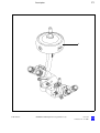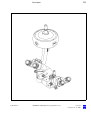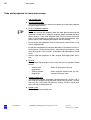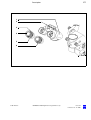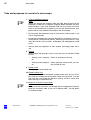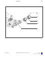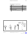
1
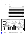
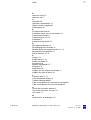
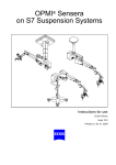
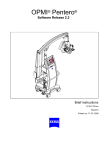
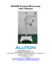
OPMI® VISU 200 BrightFlex™
Surgical Microscope
Instructions for use
G-30-1439-en
Issue 3.0
Printed on 21. 11. 2002
Contents
G-30-1439-en
Functions at a glance
5
– VISU 200 BrightFlex™ surgical microscope
6
– Key to symbols
7
Safety
9
– Directives and standards
10
– Notes on installation and use
11
– When using a fundus imaging system (e.g. BIOM II)
14
– Phototoxic retinal injury in eye surgery
14
– Warning labels and notes
18
Description
19
VISU 200 BrightFlex™ Surgical Microscope
20
– Intended use
20
– Description of the modules
20
– Illumination system
28
– Controls, displays, connections
30
– Hand grips (option)
38
– Tube and eyepieces for main microscope
40
– Tube and eyepieces for assistant's microscope
42
Preparations for use
45
– Mounting the binocular tubes, eyepieces and the objective lens
46
Operation
49
Preparations for use
50
– Adjusting the tilt angle
50
– Setting the microscope tilt to angles greater than 15°
52
– Adjusting the surgical microscope
53
– Checklist
54
– When using a fundus imaging system (e.g. BIOM II)
56
OPMI® VISU 200 BrightFlex™ Surgical Microscope
Issue 3.0
Printed on 21. 11. 2002
Procedure
57
What to do in an emergency
59
–
Failure of zoom system
59
–
Failure of X-Y coupling
60
–
Failure of focusing system
60
Maintenance / Further information
61
–
Trouble-shooting table
62
–
Magnifications / Fields of view
64
–
Care of the unit
65
–
Sterilization
66
–
Ordering data
67
–
Spare parts
68
–
Accessories
68
–
Adapter cables
70
Technical data
71
–
Technical data
72
–
Ambient requirements
74
Index
G-30-1439-en
OPMI® VISU 200 BrightFlex™ Surgical Microscope
75
Issue 3.0
Printed on 21. 11. 2002
5
Functions at a glance
Functions at a glance
G-30-1439-en
VISU 200 BrightFlex™ surgical microscope
6
Key to symbols
7
OPMI® VISU 200 BrightFlex™ Surgical Microscope
Issue 3.0
Printed on 21. 11. 2002
6
Functions at a glance
VISU 200 BrightFlex™ surgical microscope
1
Resetting the X-Y coupling, focus and zoom to their initial
positions
2 Adjusting the tilt of the surgical microscope
3 Setting the interpupillary distance
4 Adjusting the eyecups
5 Setting your prescription
6 Display of the magnification factor of the zoom system
7 Setting the red reflex illumination (+2° and -2°)
8 Releasing the magnetic brakes of the suspension system
9 Changing the magnification on assistant's microscope
10 Focusing of assistant's microscope
11 Setting the 6° illumination
12 Arrows indicating the focusing range
13
14
15
16
Locking screw for assistant's microscope (vertical)
Selecting light stops
Connecting the light guide
Locking screw for assistant's microscope (horizontal)
Page 30
Page 50
Page 40
Page 40
Page 40
Page 32
Page 28
Page 32
Page 34
Page 34
Page 36
Pages
30, 56
Page 34
Page 36
Page 36
Page 36
1
2
3
4
5
6
7
G-30-1439-en
8
9
10 5
4
11
12 8
OPMI® VISU 200 BrightFlex™ Surgical Microscope
10 9 13
14
15 16
Issue 3.0
Printed on 21. 11. 2002
7
Functions at a glance
Key to symbols
Different symbols used in this user's manual draw your attention to safety
aspects and useful tips. The symbols are explained in the following.
Warning!
The warning triangle indicates potential sources of danger which may
constitute a risk of injury for the user or a health hazard.
Caution:
The square indicates situations which may lead to malfunction, defects,
collision or damage of the instrument.
Note:
The hand indicates hints on the use of the instrument or other tips for the
user.
OPMI®
G-30-1439-en
OPMI® is a registered trademark of Carl Zeiss.
OPMI® VISU 200 BrightFlex™ Surgical Microscope
Issue 3.0
Printed on 21. 11. 2002
8
Functions at a glance
G-30-1439-en
OPMI® VISU 200 BrightFlex™ Surgical Microscope
Issue 3.0
Printed on 21. 11. 2002
9
Safety
Safety
G-30-1439-en
Directives and standards
10
Notes on installation and use
11
When using a fundus imaging system (e.g. BIOM II)
14
Phototoxic retinal injury in eye surgery
14
Warning labels and notes
18
OPMI® VISU 200 BrightFlex™ Surgical Microscope
Issue 3.0
Printed on 21. 11. 2002
10
Safety
The instrument described in this manual has been developed and tested
in accordance with Carl Zeiss safety standards and with national and international regulations. A high degree of instrument safety is thus ensured.
We would like to inform you on the safety aspects involved in operating
the instrument. This chapter contains a summary of the most important
precautions to be observed.
Further safety notes are also contained in other parts of this user's
manual; they are marked with a warning triangle containing an exclamation mark as shown here. Please pay special attention to these safety
notes.
Safety is only ensured when this instrument is operated properly. Please
read through this manual carefully before turning the instrument on. Also
read through the user's manuals of the other equipment used with this instrument. You may obtain further information from our service organization or authorized representatives.
Directives and standards
The instrument described in this manual has been designed in compliance with the following standards:
–
EN
–
IEC
–
UL
–
CSA
In accordance with Directive 93/42/EEC, the complete quality management system of the company Carl Zeiss has been certified by the DQS
Deutsche Gesellschaft zur Zertifizierung von Managementsystemen
mbH, a notified body, under registration number 250758 MR2.
G-30-1439-en
•
The instrument must be connected to a special emergency backup
line supply in accordance with the regulations or directives which apply in your country.
•
This is a class I instrument as defined by Directive 93/42 /EEC.
•
Please observe all applicable accident prevention regulations.
OPMI® VISU 200 BrightFlex™ Surgical Microscope
Issue 3.0
Printed on 21. 11. 2002
11
Safety
Notes on installation and use
Safe working order
•
G-30-1439-en
Do not operate the equipment contained in the delivery package in
–
explosion-risk areas,
–
the presence of inflammable anesthetics or volatile solvents such
as alcohol, benzine or similar chemicals.
•
Do not station or use the instrument in damp rooms. Do not expose
the instrument to water splashes, dripping water or sprayed water.
•
Immediately unplug any equipment that gives off smoke, sparks or
strange noises. Do not use the instrument until our service representative has repaired it.
•
Do not place any fluid-filled containers on top of the instrument. Make
sure that no fluids can seep into the instrument.
•
Do not force cable connections. If the male and female parts do not
readily connect, make sure that they are appropriate for one another.
If any of the connectors are damaged, have our service representative
repair them.
•
Potential equalization: The instrument can be incorporated into potential equalization measures. For this purpose, contact our service department.
•
Do not use a mobile phone in the vicinity of the equipment because
the radio interference can cause the equipment to malfunction. The effects of radio interference on medical equipment depend on a number
of various factors and are therefore entirely unforeseeable.
•
Modifications and repairs on these instruments or instruments used
with them may only be performed by our service representative or by
other authorized persons.
•
The manufacturer will not accept any liability for damage caused by
unauthorized persons tampering with the instrument; this will also forfeit any rights to claim under warranty.
•
Use this instrument only for the applications described.
•
Only use the instrument with the accessories supplied. Should you
wish to use other accessory equipment, make sure that Carl Zeiss or
the equipment manufacturer has certified that its use will not impair
the safety of instrument.
OPMI® VISU 200 BrightFlex™ Surgical Microscope
Issue 3.0
Printed on 21. 11. 2002
12
Safety
•
Only personnel who have undergone training and instruction are allowed to use this instrument. It is the responsibility of the customer or
institution operating the equipment to train and instruct all staff using
the equipment.
•
Keep the user's manuals where they are easily accessible at all times
for the persons operating the instrument.
•
Never look at the sun through the binocular tube, the objective lens or
an eyepiece.
•
Do not pull at the light guide cable, at the power cord or at other cable
connections.
•
This instrument is a high-grade technological product. To ensure optimum performance and safe working order of the instrument, its safety
must be checked once every 12 months. We recommend having this
check performed by our service representative as part of regular maintenance work.
If a failure occurs which you cannot correct using the trouble-shooting
table, attach a sign to the instrument stating it is out of order and contact our service representative.
Requirements for operation
Our service representative or a specialist authorized by us will install the
instrument. Please make sure that the following requirements for operation remain fulfilled in the future:
–
All mechanical connections (details in the user's manual) which are
relevant to safety are properly connected and screw connections tightened.
–
All cables and plugs are in good working condition.
–
The voltage setting on the instrument conforms to the rated voltage of
the line supply on site.
–
The instrument is plugged into a power outlet which has a properly
connected protective earth contact.
–
The power cord being used is the one designed for use with this instrument.
Before every use and after re-equipping the instrument
G-30-1439-en
•
Make sure that all ”Requirements for operation” are fulfilled.
•
Go through the checklist.
•
Re-attach or close any covers, panels or caps which have been removed or opened.
OPMI® VISU 200 BrightFlex™ Surgical Microscope
Issue 3.0
Printed on 21. 11. 2002
13
Safety
•
Pay special attention to warning symbols on the instrument (triangular
warning signs with exclamation marks), labels and any parts such as
screws or surfaces painted red.
For every use of the instrument
G-30-1439-en
•
Avoid looking directly into the light source, e.g. into the microscope objective lens or a light guide.
•
Any kind of radiation has a detrimental effect on biological tissue.This
also applies to the light illuminating the surgical field. Please therefore
reduce the brightness and duration of illumination on the surgical field
to the absolute minimum required.
•
When operating on the eye, always use a GG 475 protection filter to
ensure that the patient's retina is not exposed to unnecessary (blue)
radiation (retinal injury).
OPMI® VISU 200 BrightFlex™ Surgical Microscope
Issue 3.0
Printed on 21. 11. 2002
14
Safety
When using a fundus imaging system (e.g. BIOM II)
When using a fundus imaging system (e.g. BIOM II from the company Oculus) which is usually installed between the surgical microscope and the
patient, make sure that the patient is neither put at risk nor injured by the
motorized focusing system or the movement of the stand arm.
Only use accessories expressly certified by the manufacturer for combination with the surgical microscope described in this manual.
Caution!
Risk of collision!
1
•
With the fundus imaging system swung out of position, always position
the microscope body in such a way that index dot (1) of the microscope's focus is in the middle of triangle (2) of the marking.
•
Select a medium magnification (e.g. 1.0).
•
Lower the surgical microscope towards the surgical field until you see
the patient's cornea sharply defined.
•
Turn the screw for limiting the downward movement clockwise as far
as it will go.
•
It is vital that you read the user’s manual on the fundus imaging system (e.g. BIOM II from the company Oculus).
2
Phototoxic retinal injury in eye surgery
General
Several papers have been published dealing with the problems of phototoxicity during eye surgery. A comprehensive review of these publications
reveals five aspects of particular concern:
G-30-1439-en
–
Illumination characteristics (spectral composition)
–
Intensity of illumination
–
Angle of illumination
–
Focus of the light source
–
Exposure time to light
OPMI® VISU 200 BrightFlex™ Surgical Microscope
Issue 3.0
Printed on 21. 11. 2002
15
Safety
In the following, comments on these aspects are given and a description
of how Carl Zeiss, as a manufacturer, makes allowance for them in its instruments.
Illumination characteristics (spectral composition)
Studies on exposure of the eye to light of varying spectral composition
date back to the early 1950s. These studies suggest that the potential
hazard of phototoxic injury to the patient's retina can be reduced by
blocking out the blue and ultraviolet light below a wavelength of 475 nm.
Carl Zeiss provides a GG 475 retina protection filter for surgical microscopes recommended for use in ophthalmic surgery. This reduces not
only the light exposure of the patient's eye, but also that of the surgeon's.
It should be noted in this context that the use of filters inevitably leads to
a change in the color of the light. The surgeon may therefore have to get
used to the changed appearance of anatomical structures.
Intensity of illumination
The majority of researchers suggest that the surgeon should use the
lowest light intensity necessary to guarantee good viewing during surgery.
Carl Zeiss has addressed this concern by providing a device for continuously varying the brightness of the light source. This permits the surgeon
to optimally adapt the light intensity at the patient's eye to the conditions
existing in each case. Carl Zeiss strongly discourages the use of xenon or
other high-intensity light sources in ophthalmology.
Angle of illumination
A number of publications suggest that the microscope should be tilted to
reduce the exposure of the macula to direct illumination.
Carl Zeiss ophthalmic surgical microscopes are therefore equipped with
the following:
– Tilting mechanism for the microscope body
– Oblique illumination with brightness control
Focus of the light source
Studies show that injuries are likely to occur if the filament of the light
source is imaged on the patient's retina. The peak intensity of a filament
is considerably higher than the peak intensity of an even and extended
light source such as a fiber guide.
G-30-1439-en
OPMI® VISU 200 BrightFlex™ Surgical Microscope
Issue 3.0
Printed on 21. 11. 2002
16
Safety
This is the reason why fiber optic illumination is used in surgical microscopes from Carl Zeiss.
Exposure time to light
According to some publications, the phakic or aphakic eye should not be
exposed to the light source longer than a few minutes. In every operation
the exposure of the retina to light is dependent on the type and duration
of surgery and on any complications which occur. It is therefore recommended in ophthalmic surgery to keep the light intensity as low as possible, or to use a device which prevents the light from entering through the
patient's pupil. Also, the surrounding light sources should not cause additional strain to the patient's eye.
Carl Zeiss has provided an answer to this problem in the form of a swingin retinal protection device for insertion into the beam path of the surgical
microscope. This device ensures total eclipsing of the pupil, preventing
light from entering into the patient's eye. It can be swung out when a red
reflex is required.
Intensity scale
The intensity scale of our suspension system is calibrated in units of the
”Spectrally weighted radiance for the photochemical hazard of the phakic
eye (LB)”
LB is the spectral radiance integrated over the spectral range from 380 nm
to 700 nm and weighted with B(λ):
700
LB =
∑ L(λ) B(λ) ∆λ
380
in which B(λ) is the spectral weighting function for the photochemical hazard of the retina of the phakic eye.
The value LB = 500mW/cm² sr is the reference value and is defined as
1.0 on the intensity scale of the suspension system as recommended in
the ISO 10936-2 standard draft for surgical microscopes used in ophthalmic applications. At this reference value, photoretinitis might be expected to occur from the surgical microscope light source in a total retinal
exposure time of 10 minutes. This applies to the exposure of a specific
point on the retina with an uninterrupted illumination beam. In a cataract
procedure, instruments such as the phacoemulsification handpiece, the
G-30-1439-en
OPMI® VISU 200 BrightFlex™ Surgical Microscope
Issue 3.0
Printed on 21. 11. 2002
17
Safety
use of fluids in the eye, manipulation and movement of the eye, among
other factors, result in the interruption of the illumination from the surgical
microscope light source. Such factors would be expected to significantly
extend the time at which photoretinitis might occur.
In conclusion
Carl Zeiss recommends:
– Use of the GG 475 eye protection filter.
– Reduction of the illumination of the surgical area to the extent required
for the patient's safety and for microscopic visualization.
– Tilting of the microscope body as required.
– Insertion of the retinal protection device.
– Maximum reduction of the exposure of the patient's eye to light from
surrounding light sources.
These measures should help the surgeon to reduce the likelihood of phototoxic retinal injury.
Note:
The VISU 150 microscope always contains a UV blocking filter.
The use of this filter ensures that the illumination intensity lies below 50
µW/cm2 in the range between 305 nm and 400 nm.
These measures help the surgeon to reduce the risk of phototoxic retinal
injury.
G-30-1439-en
OPMI® VISU 200 BrightFlex™ Surgical Microscope
Issue 3.0
Printed on 21. 11. 2002
18
Safety
Warning labels and notes
Caution:
Observe all warning labels and notes!
If any label is missing on your instrument or has become illegible, please
contact us or one of our authorized representatives. We will supply the
missing labels.
G-30-1439-en
OPMI® VISU 200 BrightFlex™ Surgical Microscope
Issue 3.0
Printed on 21. 11. 2002
Description
19
VISU 200 BrightFlex™ Surgical Microscope
20
Intended use
20
Description of the modules
20
Illumination system
28
Controls, displays, connections
30
Hand grips (option)
38
Tube and eyepieces for main microscope
40
Tube and eyepieces for assistant's microscope
42
Description
G-30-1439-en
OPMI® VISU 200 BrightFlex™ Surgical Microscope
Issue 3.0
Printed on 21. 11. 2002
20
Description
VISU 200 BrightFlex™ Surgical Microscope
Intended use
The VISU 200 BrightFlex™ surgical microscope has been designed for
surgical procedures in the field of ophthalmology, i.e. the microscope
meets the special requirements of this discipline.
Description of the modules
The VISU surgical microscope is comprised of the following modules:
1
X-Y coupling
The X-Y coupling allows fine, motorized positioning of the surgical microscope in a horizontal plane. The range of travel is 40 mm x 40 mm.
The speed of travel can be set on the display field of the suspension
system.
The X-Y coupling is provided with a recentering mechanism. When
you press the actuator button,
–
the X-Y coupling adopts its center position,
–
the focusing system of the surgical microscope is reset to its initial
position and
–
the zoom system will set a preselected magnification factor if the
XYZ-RES function has been activated (possible with S8 suspension systems only).
You can also trigger the recentering movement using the foot control
panel..
G-30-1439-en
OPMI® VISU 200 BrightFlex™ Surgical Microscope
Issue 3.0
Printed on 21. 11. 2002
21
Description
1
G-30-1439-en
OPMI® VISU 200 BrightFlex™ Surgical Microscope
Issue 3.0
Printed on 21. 11. 2002
22
Description
2
Support arm for the surgical microscope
The support arm incorporates a tilt device. This allows the viewing direction of the surgical microscope to be adapted to the requirements
of the surgical field. Using the knob for fine tilt, you can position the
surgical microscope in a range from +180° to -180° (+ in the direction
of the surgeon and - in the opposite direction). The +90° setting is ideal
for surgery on patients in a seated position or lying on their side.
Caution:
Do not tilt the main microscope beyond + / - 180°, as this could
damage the microscope cable or the light guide.
3
Main microscope
The apochromatic optics of the main microscope provide superb optical quality. The microscope image displays optimum contrast and excellent detail recognition along with a large depth of field. The bright
microscope image is a particular benefit in vitreoretinal surgery. A 1:6
ratio zoom system allows the magnification of the overall system to be
set as required by the surgical procedure.
Two apochromatic objective lenses with focal lengths of 175 mm and
200 mm are available for different working distances.
A 180° tiltable tube is used as a viewing device for the surgeon. The
large tilt range allows work with minimum fatigue.
The standard equipment includes eyepieces with a magnification
factor of 12.5x (option: 10x).
The illumination system has been designed for use in ophthalmology.
A light guide directs the light from the light source in the suspension
system to the surgical microscope.
6° illumination can be continuously faded in. This allows the illumination intensity in the surgical field to be adjusted continuously, without
changing the color of the light. The illumination of the surgical field at
an angle of 6° produces an image with an outstanding impression of
depth.
An additional illumination system produces an intensive red reflex
even when the eye is decentered. The angle of illumination can be
switched from +2° to -2°.
G-30-1439-en
OPMI® VISU 200 BrightFlex™ Surgical Microscope
Issue 3.0
Printed on 21. 11. 2002
23
Description
2
3
G-30-1439-en
OPMI® VISU 200 BrightFlex™ Surgical Microscope
Issue 3.0
Printed on 21. 11. 2002
24
Description
To protect the patient's eye against photo-retinitis, a retinal protection device is provided. This device can be swung into the illumination beam
path, if no red reflex is required.
At the light source integrated in the stand, a GG 475 eye protection filter
can be swung into the illumination beam path. This filter markedly reduces
the exposure of the patient's and surgeon's eyes to radiation.
A video camera from our MediLive video camera line can be optionally
connected to the VISU 200 surgical microscope. The light loss for the surgeon is only 20% and cannot be perceived subjectively.
Caution!
G-30-1439-en
–
Avoid looking directly into the light source, e.g. into the microscope objective lens or into the light guide!
–
When selecting the brightness level for the patient's eye, always take
care to keep the strain on the patient's eye to a minimum.
–
If the red reflex is not necessary, move the retinal protection device
into the beam path. Only use the retro-illumination contrast stop, if the
surgical procedure requires a red reflex.
–
When operating on the eye, always use a GG 475 eye protection filter
to ensure that the patient's retina is not exposed to unnecessary (blue)
radiation (retinal injury)!
OPMI® VISU 200 BrightFlex™ Surgical Microscope
Issue 3.0
Printed on 21. 11. 2002
25
Description
G-30-1439-en
OPMI® VISU 200 BrightFlex™ Surgical Microscope
Issue 3.0
Printed on 21. 11. 2002
26
Description
4
0° assistant's microscope
The assistant's microscope is an integral part of the VISU 200 BrightFlex™ surgical microscope, i.e. it cannot be separated from the main
microscope. The assistant sees the same image as the main surgeon.
The system's excellent image quality is also available to the assistant.
The assistant's microscope has two working positions. They are located on the right and left of the main surgeon at an angle of 90° to the
main surgeon's viewing direction. No locking mechanism has been
provided, allowing the assistant to move the microscope by a certain
amount out of the 90° position, if necessary.
Warning!
To prevent the assistant's microscope from moving downward of its
own accord when the main microscope is being tilted, the assistant's
microscope must be adjusted and locked in position using screw (5)
before surgery.
The assistant's microscope is equipped with a focusing system and a
5-step magnification changer. This enables the assistant to adjust his
microscope image independently of the main surgeon.
The binocular tube can be turned by ± 12° about the optical axis of the
assistant's microscope. In addition, the assistant's microscope can be
tilted by 15°. If the assistant finds the viewing angle too steep, an optical wedge (option) can be installed between the microscope body
and the binocular tube to permit horizontal viewing.
The standard equipment includes eyepieces with a magnification
factor of 10x, providing a low initial magnification. This provides the
benefit of a wide field of view and an improved overview of the surgical
field. The assistant sees the red reflex in both eyepieces.
5
G-30-1439-en
Locking screw for assistant's microscope
After adjusting the assistant's microscope as required, secure it in position using this screw.
OPMI® VISU 200 BrightFlex™ Surgical Microscope
Issue 3.0
Printed on 21. 11. 2002
27
Description
4
5
G-30-1439-en
OPMI® VISU 200 BrightFlex™ Surgical Microscope
Issue 3.0
Printed on 21. 11. 2002
28
Description
Illumination system
6° illumination
You can continuously fade out the 6° illumination. This results in markedly
reduced reflection from the cornea, while providing nevertheless a highcontrast, informative microscope image.
For cataract surgery, we recommend opening the 6° illumination system
approx. 25%.
2° illumination
You can switch the illumination from +2° to -2°. This ensures good visibility of the red reflex even when the patient's eye is decentered.
1
2
6° illumination and 2° illumination
2° illumination with centered patient's eye
Here, the red reflex is clearly visible in both positions (+2° and -2°).
3
2° illumination with decentered patient's eye
The red reflex is no longer visible at +2°. After switching to -2°, the red
reflex is again clearly visible.
+ 6°
- 2°
G-30-1439-en
+ 2°
OPMI® VISU 200 BrightFlex™ Surgical Microscope
Issue 3.0
Printed on 21. 11. 2002
29
Description
1
2
G-30-1439-en
3
OPMI® VISU 200 BrightFlex™ Surgical Microscope
Issue 3.0
Printed on 21. 11. 2002
30
Description
Controls, displays, connections
1
Instrument connector
2
Microscope shaft
3
X-Y coupling
4
Actuator button
–
recenters the X-Y coupling.
–
resets the focus to its initial position in the focusing range, and
–
the zoom system will set a preselected magnification factor if the
XYZ-RES function has been activated (possible with S8 suspension systems only).
Note:
Press this button to start the recentering movement. To stop this
movement, press the button again.
You can also stop the recentering movement by briefly tipping on one
of the direction keys on the foot control panel.
G-30-1439-en
5
Cable and light guide clip
6
Support arm with tilt device
7
Knob
for setting the tilt angle of the surgical microscope;
+180° in the direction of the surgeon,
-180° in the opposite direction.
8
Arrows indicating the focusing range
OPMI® VISU 200 BrightFlex™ Surgical Microscope
Issue 3.0
Printed on 21. 11. 2002
31
Description
1
2
3
4
5
6
7
8
G-30-1439-en
OPMI® VISU 200 BrightFlex™ Surgical Microscope
Issue 3.0
Printed on 21. 11. 2002
32
Description
9
Dust cover
10 Release buttons for the magnetic brakes of the stand
Only in connection with suspension systems with magnetric brakes.
A second button with the same function is located on the opposite side
in the knob for the additional red reflex illumination.
–
Button pressed
magnetic brakes are released, the unit
can be moved as required.
–
Button released
magnetic brakes are locked, the unit
cannot be moved.
11 Maneuvering grip including release button. See (10).
12 Display of the magnification factor of the zoom system
13 Securing screw
G-30-1439-en
OPMI® VISU 200 BrightFlex™ Surgical Microscope
Issue 3.0
Printed on 21. 11. 2002
33
Description
9
10
11
G-30-1439-en
12
13
OPMI® VISU 200 BrightFlex™ Surgical Microscope
Issue 3.0
Printed on 21. 11. 2002
34
Description
14 Manual adjustment of zoom system
15 Knob for adjusting the red reflex illumination
The angle of illumination can be switched between + 2° and - 2°.
16 Release button for magnetic brakes
(A second button with the same function is located in maneuvering
grip (10).
–
Button pressed
magnetic brakes are released, the unit
can be moved as required.
–
Button released
magnetic brakes are locked, the unit
cannot be moved.
17 Securing screw
for locking the assistant's tube within its 12° range of movement.
18 Binocular tube of the assistant's microscope
19 Focusing knob
for adjusting the assistant's microscope independently of the main
surgeon.
20 Five-step manual magnification changer
21 Screw
for locking the assistant's microscope within its 15° tilt range.
G-30-1439-en
OPMI® VISU 200 BrightFlex™ Surgical Microscope
Issue 3.0
Printed on 21. 11. 2002
35
Description
14
15
16
17
18
19
20
G-30-1439-en
21
OPMI® VISU 200 BrightFlex™ Surgical Microscope
Issue 3.0
Printed on 21. 11. 2002
36
Description
22 Light stop knob
Retro-illumination contrast stop.
This stop reduces the straylight reflected from the sclera.
Diameter approx. 16 mm (with objective lens f = 200 mm): Free
passage.
Diameter over approx. 16 mm: Partially transmitting periphery.
Free passage. The field of view is fully illuminated.
Retinal protection device. This device does not snap in, i.e. it
can be moved continuously in the image.
23 Adjusting lever for the 6° illumination
for gradual fading in/out the coaxial illumination. Fading out the 6° illumination improves the visualization of structures in retro-illumination.
24 Connector socket for S light guide
25 Locking screw for assistant's microscope
for locking the assistant's microscope in both working positions on the
right and left of the main microscope.
Warning!
To prevent the assistant's microscope from moving downward of its
own accord when the main microscope is being tilted, the assistant's
microscope must be adjusted and locked in position using screw (25)
before surgery.
G-30-1439-en
OPMI® VISU 200 BrightFlex™ Surgical Microscope
Issue 3.0
Printed on 21. 11. 2002
37
Description
22
G-30-1439-en
23
OPMI® VISU 200 BrightFlex™ Surgical Microscope
24
25
Issue 3.0
Printed on 21. 11. 2002
38
Description
Hand grips (option)
In addition to the maneuvering grips provided, larger hand grips can be
mounted. The mounting procedure is described in the instructions enclosed.
This does not affect the functioning of the surgical microscope. Only the
operation of the surgical microscope is slightly changed.
1
2
G-30-1439-en
Maneuvering grip with integrated release button
By turning one of the two maneuvering grips you will activate the
button for magnetic brakes of the suspension system.
(Only in combination with suspension systems with magnetic brakes
(e.g. S8 Floor Stand)).
–
Button pressed
Magnetic brakes are released, the unit
can be moved as required.
–
Button released
Magnetic brakes are locked, the unit
cannot be moved.
Knob for adjusting the red reflex illumination
By sliding the knob, you can switch the angle of illumination between
+ 2° and - 2°.
OPMI® VISU 200 BrightFlex™ Surgical Microscope
Issue 3.0
Printed on 21. 11. 2002
39
Description
1
2
1
G-30-1439-en
OPMI® VISU 200 BrightFlex™ Surgical Microscope
Issue 3.0
Printed on 21. 11. 2002
40
Description
Tube and eyepieces for main microscope
G-30-1439-en
1
180° tiltable tube
2
PD adjustment knob
The correct interpupillary distance has been set when both eyepiece
images merge into one.
3
Push-in widefield eyepiece
Note:
When you remove the eyepiece from the tube, please note that this
eyepiece is fitted with a magnetic coupling. When mounted, the eyepieces display a very weak magnetic field. For this reason, the usual
rules for the handling of magnets must only be observed with eyepieces which have not been mounted on the microscope:
•
Do not place the eyepieces close to instruments where there is any
risk of magnetization.
•
Do not place eyepieces on sensitive electronic instruments such as infusion pumps, cardiac pace-makers, measuring instruments or magnetic data carriers such as disks, audiotapes and videotapes or credit
cards.
•
Always store the eyepieces in their original packaging when not in
use.
4
Eyecup
Always adjust the eyecups in such a way that you can see the full field
of view.
–
Viewing with
eyeglasses:
Screw in eyecups all the way.
–
Viewing without
eyeglasses:
Screw eyecups outward until you can
see the full field of view.
5
Diopter setting ring
The eyepieces provide ametropia compensation from -8 D to +5 D. If
you wear your eyeglasses during work, adjust the ring to 0 D. Turn the
ring until you have found the optimum setting. A built-in catch lever
locks the ring in the position set.
6
Diopter scale
For reading the prescription set.
OPMI® VISU 200 BrightFlex™ Surgical Microscope
Issue 3.0
Printed on 21. 11. 2002
41
Description
1
2
3
4
5
6
G-30-1439-en
OPMI® VISU 200 BrightFlex™ Surgical Microscope
Issue 3.0
Printed on 21. 11. 2002
42
Description
Tube and eyepieces for assistant's microscope
7
Push-in widefield eyepiece
Note:
When you remove the eyepiece from the tube, please note that this
eyepiece is fitted with a magnetic coupling. When mounted, the eyepieces display a very weak magnetic field. For this reason, the usual
rules for the handling of magnets must only be observed with eyepieces which have not been mounted on the microscope:
•
Do not place the eyepieces close to instruments where there is any
risk of magnetization.
•
Do not place eyepieces on sensitive electronic instruments such as infusion pumps, cardiac pace-makers, measuring instruments or magnetic data carriers such as disks, audiotapes and videotapes or credit
cards.
•
Always store the eyepieces in their original packaging when not in
use.
8
Eyecup
Always adjust the eyecups in such a way that you can see the full field
of view.
9
–
Viewing with eyeglass- Screw in eyecups all the way.
es:
–
Viewing w/out eyeglass- Screw eyecups outward until you see
es:
the full field of view.
Diopter scale
For reading the prescription set.
10 Diopter setting ring
The eyepieces provide ametropia compensation from -8 D to +5 D.If
you wear your eyeglasses during work, adjust the ring to 0 D. Turn the
ring until you have found the optimum setting. A built-in catch lever
locks the ring in the position set.
11 Binocular assistant's microscope
Note:
Always use the assistant's microscope with the appropriate (shown)
binocular assistant's tube. If you use a different tube, you will obtain
an inverted image.
G-30-1439-en
OPMI® VISU 200 BrightFlex™ Surgical Microscope
Issue 3.0
Printed on 21. 11. 2002
43
Description
7
8
9
10
11
G-30-1439-en
OPMI® VISU 200 BrightFlex™ Surgical Microscope
Issue 3.0
Printed on 21. 11. 2002
44
Description
G-30-1439-en
OPMI® VISU 200 BrightFlex™ Surgical Microscope
Issue 3.0
Printed on 21. 11. 2002
45
Preparations for use
Preparations for use
Mounting the binocular tubes, eyepieces and the objective lens
G-30-1439-en
OPMI® VISU 200 BrightFlex™ Surgical Microscope
Issue 3.0
Printed on 21. 11. 2002
46
46
Preparations for use
Mounting the binocular tubes, eyepieces and the objective lens
Note:
Always use the assistant's microscope with the appropriate binocular assistant's tube (shown). If you use a different tube, you will obtain an inverted image.
•
Loosen securing screw (5) by a few turns.
•
Remove cover (1) and store it in a safe place.
•
Place binocular tube (2) on the surgical microscope and tighten securing screw (5) firmly.
•
You can install other units between the binocular tube and the microscope body. Lock these units in position in the same way using securing screw (5).
•
Place binocular tube (10) on the assistant's microscope and tighten
securing screw (7)firmly.
•
You can install other units between the binocular tube and the microscope body (e.g. an optical wedge, 30°). Lock these units in position
in the same way using securing screw (7).
•
Insert 12.5x widefield eyepieces (4) into the mounts intended for them
(3) as far as they will go. The magnetic coupling reliably secures them
in position.
•
Insert 10x widefield eyepieces (9) into the mounts intended for them
(8) as far as they will go. The magnetic coupling reliably secures them
in position.
Note:
If a documentation device is used, one of the eyepieces can be delivered
with a reticle to aid focusing. Retrofitting the reticle can only be performed
at the factory or by our service representative. Always use the eyepiece
with reticle on the same side of the binocular tube as the documentation
device is installed.
•
G-30-1439-en
Screw objective lens (6) into the microscope body and tighten itfirmly.
OPMI® VISU 200 BrightFlex™ Surgical Microscope
Issue 3.0
Printed on 21. 11. 2002
47
Preparations for use
Caution:
Before using and after re-equipping the unit, make sure that the two binocular tubes (2 and 10) are securely locked in position. Make sure that
– securing screws (5 and 7) and
– objective lens (6)
have been tightened firmly.
1
2
3
10
4
9
8
5
7
6
G-30-1439-en
OPMI® VISU 200 BrightFlex™ Surgical Microscope
Issue 3.0
Printed on 21. 11. 2002
48
Preparations for use
G-30-1439-en
OPMI® VISU 200 BrightFlex™ Surgical Microscope
Issue 3.0
Printed on 21. 11. 2002
Operation
49
Preparations for use
50
Adjusting the tilt angle
50
Setting the microscope tilt to angles greater than 15°
52
Adjusting the surgical microscope
53
Checklist
54
When using a fundus imaging system (e.g. BIOM II)
56
Procedure
57
What to do in an emergency
59
Failure of zoom system
59
Failure of X-Y coupling
60
Failure of focusing system
60
Operation
G-30-1439-en
OPMI® VISU 200 BrightFlex™ Surgical Microscope
Issue 3.0
Printed on 21. 11. 2002
50
Operation
Preparations for use
Adjusting the tilt angle
Using knob (1), you can position the surgical microscope in a range from
+180° to -180° (+ in the direction of the surgeon and - in the opposite direction). The +90° setting is ideal for surgery on patients in a seated position or lying on their side.
Warning!
– To prevent the assistant's microscope from moving downward of its
own accord when the main microscope is being tilted, the assistant's
microscope must be adjusted and locked in position using screw (2)
before surgery.
–
Check that the assistant's microscope is firmly seated.
–
Do not tilt the main microscope beyond + / - 180°, as this could damage the microscope cable or the light guide.
•
Using locking screw (2), secure the assistant's microscope in the
working position set (on the left or right of the main microscope).
•
Turn knob (1) until the surgical microscope is in the viewing position
required.
After the viewing angle has been set, the surgical microscope remains in
this position. The gear drive is self-locking.
G-30-1439-en
OPMI® VISU 200 BrightFlex™ Surgical Microscope
Issue 3.0
Printed on 21. 11. 2002
51
Operation
1
2
G-30-1439-en
OPMI® VISU 200 BrightFlex™ Surgical Microscope
Issue 3.0
Printed on 21. 11. 2002
52
Operation
Setting the microscope tilt to angles greater than 15°
•
Using locking screw (2), secure the assistant's microscope in the
working position set (on the left or right of the main microscope).
•
Check that the assistant's microscope is firmly seated.
•
Remove the binocular tube and all accessories mounted on the assistant's microscope.
•
Remove all accessories mounted on the objective lens (e.g. 0° or 8°
assistant's microscope).
•
Turn knob (1) until the surgical microscope is in the viewing position
required.
After the viewing angle has been set, the surgical microscope remains in
this position. The gear drive is self-locking.
2
1
G-30-1439-en
OPMI® VISU 200 BrightFlex™ Surgical Microscope
Issue 3.0
Printed on 21. 11. 2002
53
Operation
Adjusting the surgical microscope
Bring the surgical microscope into starting position within the focusing range. Set the minimum magnification on the surgical microscope. Bring the surgical microscope into working position. Adjust the interpupillary distance on the binocular tube. Set the diopter
scales on the eyepieces. Please note that instrument myopia may occur.
Eyepieces with reticles:
Eyepieces without reticles:
Emmetropes
set the diopter scale to 0 diopter (D).
Eyeglass wearers
(who perform surgery wearing their
glasses) set the diopter scale to 0 diopter (D).
Ametropes
(who know their refractive powers
and perform surgery without wearing their glasses) set the diopter
scale ring to their refractive powers.
Ametropes (who do not know their refractive powers and perform surgery
without wearing their glasses):
Set both eyepieces on the main microscope to +5 D.
Set both eyepieces on the assistant’s
microscope to +5 D (if applicable).
Set both eyepieces on the main microscope to +5 D.
Set both eyepieces on the assistant’s
microscope to +5 D (if applicable).
Remove the binocular tube and
eyepieces from the microscope
body and point them at a distant object*) , i.e. use them like a pair of
binoculars.The image of the object
is still unsharp.
Turn the diopter scale ring on the eyepiece slowly clockwise until the reticle is
imaged sharply. Stop turning the ring.
Turn the diopter scale ring of one
eyepiece slowly clockwise until the
image of the object is sharp. Stop
turning the ring. If necessary, repeat
this procedure three times and take
the average of the readings found.
Adjust the second eyepiece in the
same manner.
Focus the surgical microscope on the
object. The reticle and the object must
be imaged sharply at the same time.
Replace the tube and eyepieces on
the microscope body and firmly
tighten the securing screw.
Adjust the second eyepiece in the same
way until the object is seen sharply.
Adjust the eyecups in such a way that the full field of view can be seen. Set the maximum magnification on the microscope and focus
on the object. Set the working magnification required. When the magnification is changed, the focal plane is retained, but the depth
of field changes.
Note: If several surgeons use the instrument, it is advisable to draw up a table
showing the individual refractive powers of each surgeon and to keep it in a handy
location near the instrument.
*) CAUTION: Never point the eyepieces at the sun!
G-30-1439-en
OPMI® VISU 200 BrightFlex™ Surgical Microscope
Issue 3.0
Printed on 21. 11. 2002
54
Operation
Checklist
Always check the following points before surgery (without the patient!):
VISU 200 BrightFlex™ surgical microscope
–
Check that the correct rated voltage has been set for the suspension
system.
–
Check that all cables have been connected.
–
Check that the light guide has been connected.
•
Turn on the instrument at the power switch of the suspension system.
Note:
After the system has been switched on, the S8 suspension system(ophthalmology) automatically performs a self-test. The self-test is completed
after approx. five seconds.
Zoom
– Check this function using the appropriate key on the foot control panel.
Focus
– Check this function using the appropriate key on the foot control panel.
Friction adjustment of the surgical microscope
– Check that the friction of the surgical microscope's rotation has been
adjusted as required using the friction adjustment knob on the suspension system.
Locking the assistant's microscope in position
– Check that the assistant's microscope is locked in the working position
required (on the right or left of the main microscope).
Speeds of the surgical microscope's functions
(only in connection with S8 suspension system (ophthalmology))
–
Check that the speeds of the microscope's functions have been set as
required on the S8 suspension system (ophthalmology).
Eyepieces / Tiltable binocular tubes
– Check that the tiltable tube of the main microscope and the assistant's
microscope are in positions convenient for you.
G-30-1439-en
–
Check that the correct interpupillary distance has been set.
–
Check that the eyecups have been adjusted in such a way that you
can see the full field of view.
–
Check that the correct prescription has been set on the diopter scale.
OPMI® VISU 200 BrightFlex™ Surgical Microscope
Issue 3.0
Printed on 21. 11. 2002
55
Operation
– Check that image quality is the same throughout the entire magnification range.
Accessories
– Using the relevant user's manuals, check that the other equipment (illumination system, video system, etc.) is working properly.
Warning!
If a function fails, you must not use this instrument for safety reasons. Correct the fault (see the "Troubleshooting table“) or contact our service dept.
G-30-1439-en
OPMI® VISU 200 BrightFlex™ Surgical Microscope
Issue 3.0
Printed on 21. 11. 2002
56
Operation
When using a fundus imaging system (e.g. BIOM II)
When using a fundus imaging system (e.g. BIOM II from the company Oculus) which is usually installed between the surgical microscope and the
patient, make sure that the patient is neither put at risk nor injured by the
motorized focusing system or the movement of the stand arm.
Only use accessories expressly certified by the manufacturer for combination with the surgical microscope described in this manual.
Caution!
Risk of collision!
1
•
With the fundus imaging system swung out of position, always position
the microscope body in such a way that index dot (1) of the microscope's focus is in the middle of triangle (2) of the marking.
•
Select a medium magnification (e.g. 1.0).
•
Lower the surgical microscope towards the surgical field until you see
the patient's cornea sharply defined.
•
Turn the screw for limiting the downward movement clockwise as far
as it will go.
•
It is vital that you read the user’s manual on the fundus imaging system (e.g. BIOM II from the company Oculus).
2
G-30-1439-en
OPMI® VISU 200 BrightFlex™ Surgical Microscope
Issue 3.0
Printed on 21. 11. 2002
57
Operation
Procedure
G-30-1439-en
•
Turn on the power switch of the suspension system.
•
Adjust the brightness of the surgical field illumination as required on
the stand.
•
Check the unit using the checklist.
•
Move the surgical microscope over the surgical field and bring it into a
convenient position within the working distance.
•
Press the activator button.
–
The X-Y coupling is recentered.
–
The focus is reset to its initial position in the focusing range.
•
Select the lowest magnification (zoom function on the foot control panel).
•
For coarse focusing, look through the eyepieces and lower the surgical microscope using the suspension arm until the surgical field comes
into focus.
•
Select the highest magnification (zoom function on the foot control
panel).
•
Look through the eyepieces and activate the focusing function on the
foot control panel until the microscope is sharply focused on the surgical field.
•
Select the magnification required (zoom). Look through the eyepieces
of the binocular tube. Adjust the eyepieces (including those of the assistant's microscope) in such a way that you can see both the edge of
the field of view and the microscope image sharply. Also see “Adjusting the surgical microscope“.
•
Switch the unit off when it is not in use.
OPMI® VISU 200 BrightFlex™ Surgical Microscope
Issue 3.0
Printed on 21. 11. 2002
58
Operation
Caution!
G-30-1439-en
–
Avoid looking directly into the light source, e.g. into the microscope objective lens or into a fiber light guide!
–
When selecting the brightness level for the patient's eye, always take
care to keep the strain on the patient's eye to a minimum.
–
If the red reflex is not necessary, move the retinal protection device
into the beam path. Only use the retro-illumination contrast stop, if the
surgical procedure requires a red reflex.
–
When operating on the eye, always use a GG 475 protection filter to
ensure that the patient's eye is not exposed to unnecessary (blue) radiation (retinal injury).
OPMI® VISU 200 BrightFlex™ Surgical Microscope
Issue 3.0
Printed on 21. 11. 2002
59
Operation
What to do in an emergency
Failure of zoom system
•
Manually adjust the magnification using zoom control (1) on the microscope (if necessary, use a tool, e.g. screwdriver, coin, etc.).
1
G-30-1439-en
OPMI® VISU 200 BrightFlex™ Surgical Microscope
Issue 3.0
Printed on 21. 11. 2002
60
Operation
Failure of X-Y coupling
•
If the X-Y coupling fails, you can manually position the surgical microscope utilizing the possibilities of the suspension system you are using.
Failure of focusing system
G-30-1439-en
•
Disconnect the cable between the surgical microscope and the suspension system (illumination continues to be on.)
•
Focus the surgical microscope by moving the suspension arm or the
lift arm of the suspension system you are using.
OPMI® VISU 200 BrightFlex™ Surgical Microscope
Issue 3.0
Printed on 21. 11. 2002
61
Maintenance / Further information
Maintenance / Further information
G-30-1439-en
Trouble-shooting table
62
Magnifications / Fields of view
64
Care of the unit
65
Sterilization
66
Ordering data
67
Spare parts
68
Accessories
68
Adapter cables
70
OPMI® VISU 200 BrightFlex™ Surgical Microscope
Issue 3.0
Printed on 21. 11. 2002
62
Maintenance / Further information
Trouble-shooting table
•
This instrument is a high-grade technological product. To ensure optimum performance and safe working order of the instrument, its safety
must be checked once every 12 months. We recommend having this
check performed by our service representative as part of regular maintenance work.
If a failure occurs which you cannot correct using the trouble-shooting
table, attach a sign to the instrument stating it is out of order and contact our service representative.
VISU 200 BrightFlex™ Surgical Microscope
Problem
Possible cause
See
No function at all.
Power cord of suspension Plug in power cord.
system not plugged in.
-
Power switch of suspension Press power switch. Green system not on.
light in power switch must
come on.
Circuit breaker in suspen- Press power switch again.
sion system power switch
activated.
Line power failure.
Contact
cian.
in-house
-
electri- -
Lamp module has no con- Insert lamp module as far as tact.
it will go.
Surgical field illumination at Illumination system of sus- Switch
microscope inoperative.
pension
system
not system
switched on.
system.
on
of
illumination suspension
S light guide not properly in- Insert S light guide as far as serted in lamp or micro- it will go.
scope.
Failure
of
suspension Illuminate surgical field system electronics.
using an OR illuminator.
Contact service dept.
G-30-1439-en
OPMI® VISU 200 BrightFlex™ Surgical Microscope
Issue 3.0
Printed on 21. 11. 2002
63
Maintenance / Further information
Problem
Possible cause
See
Insufficient surgical field illu- Brightness level set too low. Adjust brightness on sus- mination.
pension system or using
foot control panel.
Defective S light guide (no Contact service dept.
homogeneous illumination). The light guide must probably be changed.
Focusing function inopera- Connectors on suspension Plug in connectors correctly. tive.
system not correctly inserted.
Focusing system always Check suspension system. moves into upper or lower Move the suspension arm to
end position.
adjust the focus.
Contact service dept.
Zoom function inoperative.
Connectors on suspension Plug in connectors correctly. system not correctly inserted.
Zoom system always moves Check suspension system. page 34
into upper or lower end posi- Manually adjust magnification.
tion using the zoom knob.
Contact service dept.
X-Y coupling inoperative.
Connectors on suspension Plug in connectors correctly. –
system not correctly inserted.
Defective motor.
Position microscope manu- ally.
Contact service dept.
X-Y coupling always moves Function not correctly ad- Check suspension system.
in opposite direction.
justed
on
suspension
system.
-
Zoom and focusing func- Functions not correctly ad- Check suspension system.
tions inoperative.
justed
on
suspension
system.
-
Microscope motion too stiff. Friction adjustment knob on Loosen friction adjustment.
suspension system tightened too firmly.
-
G-30-1439-en
OPMI® VISU 200 BrightFlex™ Surgical Microscope
Issue 3.0
Printed on 21. 11. 2002
64
Maintenance / Further information
Magnifications / Fields of view
Using the magnification factor γ of the zoom system, you can calculate the
total magnification of the surgical microscope according to the following
formula:
f tube
MT = ----------- ⋅ γ ⋅ M eye
f obj
where:
ftube is the focal length of the binocular tube
fobj is the focal length of the main objective lens
γ
is the magnification factor set on the zoom system
M eye is the magnification of the eyepiece
Example:
ftube= 170 mm, fobj = 200 mm, γ = 1.6 and M eye = 12.5 x.
The resulting total magnification is:
170 mm
MT = --------------------- ⋅ 1.6 ⋅ 12.5 = 17.0
200 mm
If the total magnification M T of the surgical microscope is known, the fieldof-view diameter FoVD can be calculated using the formula:
FoV N ⋅ M eye
FoV D = --------------------------------MT
The field-of-view diameter FoVD is the diameter of the circular area of the
surgical field which can be seen through the eyepieces.
FoVN in the above formula stands for the field-of-view number of the eyepiece. This number is marked on our widefield eyepieces.
Using M T = 17.0 from the example above, the field-of-view diameter obtained with a 12.5x eyepiece with a field-of-view number FoVN of 18 mm
is calculated as follows:
18 mm ⋅ 12.5
FoV D = ---------------------------------- = 13.2 mm
17.0
G-30-1439-en
OPMI® VISU 200 BrightFlex™ Surgical Microscope
Issue 3.0
Printed on 21. 11. 2002
65
Maintenance / Further information
Care of the unit
Cleaning optical surfaces
The multilayer T* (T-star) coating of our optical components (e.g. eyepieces, objective lenses) results in optimum image quality.
Image quality is impaired by even slight contamination of the optics or by
a fingerprint. In order to protect the internal optics from dust, the instrument should never be left without the objective lens, binocular tube and
eyepieces installed when it is not in use. Always store objective lenses,
eyepieces and accessories which are not being used in dust-free cases.
The external surfaces of optical components (eyepieces, objective
lenses) should only be cleaned when required:
•
Do not use any chemical cleaning agents.
•
Blow off dust on the optical surfaces using a squeeze blower or remove the dust using a clean and grease-free brush.
Fogging of optical surfaces
To protect the eyepiece optics from fogging, we recommend using an
anti-fogging agent.
Note:
Anti-fogging agents provided by eyecare professionals for use with eyeglass lenses are also suitable for Zeiss eyepieces.
•
Please observe the instructions for use supplied with each anti-fogging agent.
Anti-fogging agents do not only ensure fog-free optics. They also clean
the eyepiece optics and protect them against dirt, grease, dust, fluff and
fingerprints.
Cleaning mechanical surfaces
All mechanical surfaces of the equipment can be cleaned by wiping with
a moist cloth. Do not use any aggressive or abrasive cleaning agents.
Wipe off any residue with a mixture of 50% ethyl alcohol and 50% distilled
water plus a dash of household dish-washing liquid.
G-30-1439-en
OPMI® VISU 200 BrightFlex™ Surgical Microscope
Issue 3.0
Printed on 21. 11. 2002
66
Maintenance / Further information
Sterilization
The asepsis sets available from Carl Zeiss contain rubber caps, sleeves
and handgrips which can be sterilized in autoclaves. We recommend the
following program for sterilization:
Sterilization temperature:
134° C
Sterilization time:
10 minutes
Sterile single-use drapes are available to cover the instrument.
Note:
When draping the system, make sure there is enough slack in the drapes
to allow for movement of the microscope carrier and surgical microscope.
It is especially important that the drapes are completely loose around the
handgrips. The surgeon must be able to operate the keys through the
drape.
G-30-1439-en
OPMI® VISU 200 BrightFlex™ Surgical Microscope
Issue 3.0
Printed on 21. 11. 2002
67
Maintenance / Further information
Ordering data
VISU 200 BrightFlex™ Surgical Microscope
Description
Cat.No.
VISU 200 BrightFlex™ surgical microscope including 1179-101
X-Y coupling and assistant's microscope
G-30-1439-en
180° tiltable tube
30 37 91-0000
10x eyepiece for assistant's microscope (2x)
30 55 42-0000
12.5x/18 B eyepiece for main microscope (2x)
30 55 43-0000
Objective lens, f = 175 mm
30 26 51-9902
Dust cover
1055-278
OPMI® VISU 200 BrightFlex™ Surgical Microscope
Issue 3.0
Printed on 21. 11. 2002
68
Maintenance / Further information
Spare parts
VISU 200 BrightFlex™ Surgical Microscope
Description
Cat. No.
S light guide (not shown) 2.0 m
30 34 81-9020
Dust cover (not shown)
1055-278
Asepsis set (not shown)
1009.100
Accessories
Please observe the following:
Only operate the instrument with the accessories included in the delivery
package. If you want to use other accessories, make sure that Carl Zeiss
or the manufacturer of the accessories has proved and confirmed that
these accessories meet the respective technical safety standards and
can be used without risk.
G-30-1439-en
OPMI® VISU 200 BrightFlex™ Surgical Microscope
Issue 3.0
Printed on 21. 11. 2002
69
Maintenance / Further information
VISU 200 BrightFlex™ Surgical Microscope
1
G-30-1439-en
Description
Cat. No.
1
Objective lens, f = 200 mm
30 26 52-9903
2
Optical wedge, 30°
1006-145
3
Sleeve (for insertion of eyepiece (4))
30 55 42-0107
4
10x eyepiece with magnetic coupling
30 55 42-0000
5
OPMI VISU hand grips
1049- 171
Asepsis for OPMI VISU hand grips
(1x included in delivery package 1049- 171)
1054- 074
2
3
4
OPMI® VISU 200 BrightFlex™ Surgical Microscope
5
Issue 3.0
Printed on 21. 11. 2002
70
Maintenance / Further information
Adapter cables
for the electrical connection of the surgical microscope to different types
of suspension system.
Cat. No.
1
G-30-1439-en
1
EMD II Electromechanical Ceiling Mount
30 26 02- 9053
1
S3 Ceiling Mount
30 26 02- 9053
2
S4 Ceiling Mount
30 26 02- 9054
1
S23 Ceiling Mount
30 26 02- 9053
3
S6 Ceiling Mount
30 26 02- 9055
3
S61 Ceiling Mount
30 26 02- 9055
1
S22 Floor Stand
30 26 02- 9053
2
S4 Floor Stand
30 26 02- 9054
1
S3 Floor Stand
30 26 02- 9053
2
OPMI® VISU 200 BrightFlex™ Surgical Microscope
3
Issue 3.0
Printed on 21. 11. 2002
71
Technical data
Technical data
G-30-1439-en
Technical data
72
Ambient requirements
74
OPMI® VISU 200 BrightFlex™ Surgical Microscope
Issue 3.0
Printed on 21. 11. 2002
72
Technical data
Technical data
VISU 200 BrightFlex™ Surgical Microscope
Optical data
Magnification
Main microscope:
4.9x - 29x
Motorized zoom system with apochromatic optics, 1:6 zoom ratio,
magnification factor γ = 0.4x - 2.4x.
Focusing
Motorized, focusing range 50 mm
At the press of a button, the focusing drive returns
to its initial position.
Objective lens focal f = 175 mm (option: f = 200 mm)
length
Tubes / Eyepieces
Main microscope:
180° tiltable binocular tube, f=170 mm. 12.5x
screw-type, widefield eyepieces (option: 10x ).
Assistant's microscope:
5-step magnification changer, separate fine focusing, adjustable tilt.
Binocular tube, can be turned by ±12° about its
optical axis,
10x widefield eyepieces with magnetic coupling.
Illumination
Fiber illumination with two lamp modules, each
with two 12 V 100 W halogen reflector lamps,
fully automatic lamp change in the event of lamp
failure,
filter against UV exposure,
protection against IR exposure,
6° illumination (continuous fading),
patented 2° illumination for red reflex, usable in
+2° and -2° positions
Pat. No. DE40 28 60 5 C2
G-30-1439-en
OPMI® VISU 200 BrightFlex™ Surgical Microscope
Issue 3.0
Printed on 21. 11. 2002
73
Technical data
Swing-in stops
Patented retinal protection device,
Pat. No. DE 33 39 17 2 C2
Patented field stop for reduced glare,
Pat. No. G 91 03 43 3.7
Mechanical data
Front-to-back tilt of With self-locking gear drive, manually adjustable
microscope
using a knob.
Tilt angle ± 180°
Swivel range of
Swivel angle ± 90°, manually lockable
assistant's
microscope
X-Y coupling
Adjustment range: max. 40 mm x 40 mm
Automatic centering at the press of a button
Weight
G-30-1439-en
approx. 13 kg
OPMI® VISU 200 BrightFlex™ Surgical Microscope
Issue 3.0
Printed on 21. 11. 2002
74
Technical data
Ambient requirements
For operation
Temperature
Rel. humidity
Air pressure
For transportation and Temperature
storage
Rel. humidity
(without
condensation)
Air pressure
+10 °C...+40 °C
30%...75%
700 hPa...1,060 hPa
- 40 °C...+70 °C
10%...100%
500 hPa...1,060 hPa
The unit meets the essential requirements stipulated in
Annex I to the 93/42/EEC Directive governing medical devices. The unit is marked with:
Subject to change.
G-30-1439-en
OPMI® VISU 200 BrightFlex™ Surgical Microscope
Issue 3.0
Printed on 21. 11. 2002
75
Index
Index
Symbols
+90° position 50
Numerics
2° illumination 28
A
Accessories 68
Accident prevention regulations 10
Actuator button 30
Adapter cables 70
Adjusting lever for 6° illumination 36
Adjusting the microscope tilt to angles greater than 15° 52
Adjusting the surgical microscope 53
Adjusting the tilt angle 50
Ambient requirements 74
Angle of illumination 15
Anti-fogging agent 65
Arrows indicating the focusing range 30
Assistant's microscope 0° 26
B
Binocular tubes, eyepieces and objective lens, mounting of 46
Buttons for the release of the magnetic brakes 32
C
Cable and light guide clip 30
Care of the unit 65
CE marking 74
Checklist 54
Cleaning optical surfaces 65
Composition, spectral 15
Connector socket for S light guide 36
Controls, displays, connections 30
D
Description 19
Diopter scale 40, 42
Directive 93/42/EEC 74
Directives 10
E
Emergency backup line supply 10
Exposure time to light 16
Eyecup 40, 42
G-30-1439-en
OPMI® VISU 200 BrightFlex™ Surgical Microscope
Issue 3.0
Printed on 21. 11. 2002
76
Index
Eyepiece optics, fog-free 65
F
Failure of a function 55
Failure of zoom system 59
Fields of view 64
Focus of the light source 15
Focusing knob 34
Focusing system failure 60
Fogging of optical surfaces 65
Fundus imaging system 14, 56
G
GG 475 eye protection filter 17
GG 475 protection filter 13
H
Hand grips (option) 38
I
Illumination characteristics 15
Installation, notes 11
Instrument class 10
Instrument connector 30
Intensity of illumination 15
Intensity scale 16
ISO 10936-2 draft for surgical microscopes used in ophthalmic applications 16
K
Key to symbols 7
Knob for adjusting the red reflex illumination 34
L
LB 16
Light source, focus 15
Light stop knob 36
Locking screw for assistant's microscope 26, 36
M
Magnification changer 34
Magnifications 64
Main microscope 22
Main microscope, tilted 26
Maintenance 61
Manual adjustment of zoom system 34
Mechanical surfaces, cleaning 65
Microscope shaft 30
Mobile phones 11
G-30-1439-en
OPMI® VISU 200 BrightFlex™ Surgical Microscope
Issue 3.0
Printed on 21. 11. 2002
77
Index
N
Notes on safety 10
Notes on use 11
O
Operation 49
Operation, requirements 12
Optical surfaces, fogging 65
Ordering data 67
P
PD adjustment knob 40
Phototoxic retinal injury in eye surgery 14
Potential equalization 11
Preparations for use 45
Procedure 57
Protective earth contact 12
R
Red reflex illumination 38
Re-equipping the instrument 12
Release button for magnetic brakes 34, 38
Requirements for operation 12
Risk of collision! 14, 56
S
Safety 9, 10
Safety check 12, 62
Safety standards 10
Spare parts 68
Spectral composition 15
Standards 10
Sterilization 66
Support arm for surgical microscope 22
Support arm with tilt device 30
T
Technical data 71, 72
Time of exposure to light 16
Trouble-shooting table 62
Tube and eyepieces for assistant's microscope 42
Tube and eyepieces for main microscope 40
U
Use of the instrument, before 12
Use of the instrument, for every 13
Use, notes 11
W
What to do in an emergency 59
G-30-1439-en
OPMI® VISU 200 BrightFlex™ Surgical Microscope
Issue 3.0
Printed on 21. 11. 2002
78
Index
X
X-Y coupling 20, 30
X-Y coupling failure 60
G-30-1439-en
OPMI® VISU 200 BrightFlex™ Surgical Microscope
Issue 3.0
Printed on 21. 11. 2002
79
G-30-1439-en
OPMI® VISU 200 BrightFlex™ Surgical Microscope
Issue 3.0
Printed on 21. 11. 2002
Carl Zeiss
Surgical Products Division
73446 Oberkochen
Germany
G-30-1439-en
Fax: +49 (0) 7364 20-4823
E-mail: [email protected]
www.zeiss.com/surgical
Printed in Germany
MS-TD