1
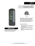
1-500
5H081501
October, 2010
INSTALLATION AND SERVICE MANUAL
HOT DAWG H2O® - Low Profile Hot Water Unit Heater
Model HHD
WARNING
Improper installation, adjustment, alteration,
service or maintenance can cause property
damage, injury or death. Read the installation,
operating and maintenance instructions
thoroughly before installing or servicing this
equipment.
IMPORTANT
The use of this manual is specifically intended
for a qualified installation and service agency. A
qualified installation and service agency must
perform all installation and service of these
appliances.
General Information
Installation and service instructions in this manual are
applicable to model HHD, low profile hot water unit heaters,
which should be installed in their proper applications for their
most effective function as heating units.
The water coils are warranted for operation at water pressures
up to 150 psi and temperatures up to 200°F.
Motors are designed for continuous duty. They can operate in
a maximum ambient temperature of 104°F (40°C).
The unit heaters are listed by ETL as certified. Units not
approved for use in potable water systems.
Table of Contents
General Information……………………………………..
Inspection on Arrival…………………………………….
Special Precautions……………………………………..
SI (Metric) Conversion Factors………………………...
Installation
Unit Location…………………………………………
Unit Mounting………………………………………..
Hot Water Piping…………………………………….
Electrical Connections………………………………
Start-Up Procedure
Prior to Operation……………………………………
Initial Start-Up………………………………………..
Typical Sequence of Operation……………………
Troubleshooting……………………………………..
Unit Data
Dimensions…………………………………………..
Electrical Data……………………………………….
Mechanical Data…………………………………….
Performance Data…………………………………...
Maintenance/Replacement Parts……………………...
Warranty………………………………………………….
1
1
2
2
3
4-5
6
6
7
7
7
7
8
8
8
9
10
12
Inspection upon Arrival
1.
2.
3.
Inspect unit upon arrival. In case of damage, report
immediately to transportation company and your local
factory sales representative.
Check rating plate on unit to verify that the power supply
meets available electric power at the point of installation.
Inspect unit received for conformance with description of
product ordered (including specifications where
applicable).
Note: Modine Manufacturing Company has a continuous
product improvement program, and therefore reserves the right
to change design and specifications without notice.
THIS MANUAL IS THE PROPERTY OF THE OWNER.
PLEASE BE SURE TO LEAVE IT WITH THE OWNER WHEN YOU LEAVE THE JOB.
SPECIAL PRECAUTIONS
THE INSTALLATION AND MAINTENANCE INSTRUCTIONS IN
THIS MANUAL MUST BE FOLLOWED TO PROVIDE SAFE,
EFFICIENT, AND TROUBLE-FREE OPERATION. IN ADDITION,
PARTICULAR CARE MUST BE EXERCISED REGARDING THE
SPECIAL PRECAUTIONS LISTED BELOW. FAILURE TO
PROPERLY ADDRESS THESE CRITICAL AREAS COULD
RESULT IN PROPERY DAMAGE OR LOSS, PERSONAL INJURY,
OR DEATH. THESE INSTRUCTIONS ARE SUBJECT TO ANY
MORE RESTRICTIVE LOCAL OR NATIONAL CODES.
CAUTION
3.
4.
5.
HAZARD INTENSITY LEVELS
1. DANGER: Indicates an imminently hazardous situation which,
if not avoided, WILL result in death or serious injury.
2. WARNING: Indicates a potentially hazardous situation which,
if not avoided, COULD result in death or serious injury.
3. CAUTION: Indicates a potentially hazardous situation which, if
not avoided, MAY result in minor or moderate injury.
4. IMPORTANT: Indicates a situation which, if not avoided, MAY
result in a potential safety concern.
6.
7.
DANGER
8.
Units must not be installed where they may be exposed to
potentially explosive or flammable atmosphere.
IMPORTANT
WARNING
1.
2.
3.
4.
5.
1.
Disconnect power supply before making wiring
connections to prevent electrical shock and equipment
damage.
All appliances must be wired strictly in accordance with
the wiring diagram furnished with the appliance. Any
wiring different from the wiring diagram could result in a
hazard to persons and property.
Any original factory wiring that requires replacement
must be replaced with wiring material having a
temperature rating of at least 105°C.
Ensure that the supply voltage to the appliance, as
indicated on the serial plate, is not 5% greater than the
rated voltage.
When servicing or repairing of this equipment, use only
factory-approved service replacement parts. A
complete replacement parts list may be obtained by
contacting Modine Manufacturing Company. Refer to
the rating plate on the unit for complete model and serial
number and Company address. Any substitution of
parts or controls not approved by the factory will be at
the owner’s risk.
2.
3.
4.
5.
6.
2.
2
Start-up and adjustment procedures should be
performed by a qualified service agency.
Be sure no obstructions block air intake and discharge
of unit heaters. Do not attach ductwork or air filters to
this unit heater. Maintain a minimum of 6” clearance to
inlet openings.
When mounting the unit to the joists, do not compress
the vibration isolators by over tightening the lag bolt
screws into the joist. Doing so will greatly reduce the
ability of the isolator to dampen vibration.
No water-flow can cause a freeze condition resulting in
damage to the coil.
Never leave the unit filled with water in a building
without heat unless antifreeze has been added.
To check most of the Possible Remedies in the
troubleshooting guide listed in Table 7.1, refer to the
applicable sections of the manual.
Table 2.1 – SI (Metric) Conversion Factors
CAUTION
1.
Units are designed for use in heating applications with
ambient temperatures between 40°F and 100°F.
Heaters should not be used in applications where the
heated space temperature is below 40°F unless a glycol
anti-freeze solution has been added.
Units not approved for use in potable water systems.
Do not install units below 7' measured from the bottom
of the unit to the floor in commercial applications (unless
unit is properly guarded to provide user protection from
moving parts) and 5' measured from the bottom of the
unit to the floor in residential applications.
Do not reuse any mechanical or electrical components
which have been wet. Replace defective components.
Do not operate the unit with steam. The coil is not
designed for steam condensate removal which can
damage the unit.
Ensure the supply voltage to the appliance, as indicated
on the serial plate, is not 5% less than the rated voltage.
All literature shipped with this unit should be kept for
future use for servicing or service diagnostics. Leave
manual with the owner. Do not discard any literature
shipped with this unit.
Consult piping and electrical instructions in this manual
before final installation.
1-500
To Convert
Multiply By
“W.C.
ºF
BTU
BTU/ft3
BTU/hr
CFH (ft3/hr)
CFH (ft3/hr)
CFM (ft3/min)
CFM (ft3/min)
0.249
(ºF-32) x 5/9
1.06
37.3
0.000293
0.000472
0.00000787
0.0283
0.000472
To
Obtain
kPa
ºC
kJ
kJ/m³
kW
m³/min
m³/s
m³/min
m³/s
To Convert
feet
Gal/hr
Gal/hr
gallons
Horsepower
inches
pound
psig
psig
Multiply
By
0.305
0.00379
3.79
3.79
746
25.4
0.454
6.89
27.7
To
Obtain
m
m³/hr
l/hr
l
W
mm
kg
kPa
“W.C.
INSTALLATION – UNIT LOCATION
Units must not be installed where they may be exposed to
potentially explosive or flammable atmosphere.
CAUTION
1.
2.
3.
4.
All literature shipped with this unit should be kept for
future use for servicing or service diagnostics. Leave
manual with the owner. Do not discard any literature
shipped with this unit.
Consult piping and electrical instructions in this manual
before final installation.
Units are designed for use in heating applications with
ambient temperatures between 40°F and 100°F.
Heaters should not be used in applications where the
heated space temperature is below 40°F unless a glycol
anti-freeze solution has been added.
Units not approved for use in potable water systems.
Figure 3.1 – Model HHD Mounting Orientations
Horizontal Air Delivery,
Perpendicular to Joists
DANGER
the unit can be flipped 180° from the way it was received
from the factory. By doing so, the sides become opposite
but the front and back remain in the same relative position.
The bottom panel now becomes the top panel and viceversa. Be sure to remove the spring loaded deflector
blades, turn them over, replace, and adjust so they are open
and in a position to direct the heated air down to the floor.
Note that the labels on the front of the unit will be upside
down. New stickers can be purchased from Modine.
IMPORTANT
1.
2.
3.
4.
5.
6.
7.
8.
9.
Horizontal Air Delivery,
Parallel to Joists
2.
Start-up and adjustment procedures should be
performed by a qualified service agency.
Be sure no obstructions block air intake and discharge
of unit heaters. Do not attach ductwork or air filters to
this unit heater. Maintain a minimum of 6” clearance to
inlet openings.
Units should not be installed in atmospheres where
corrosive fumes or sprays are present.
When locating the heater, consider general space and
heating requirements and availability of hot water and
electrical supply.
Be sure the structural support at the unit location site is
adequate to support the unit’s weight.
Determine mounting orientation of the unit heater.
Figure 3.1 shows three typical orientations. Additional
details can be seen in Figure 5.2.
Be sure no obstructions block air intake and discharge
of unit heaters. Do not attach ductwork or air filters to
this unit heater. Maintain a minimum of 6” clearance to
inlet openings. Failure to do so will result in poor unit
performance.
Unit heaters installed in a building exposed to a
prevailing wind should be located to direct a major
volume of heated air along the windward wall.
Vertical delivery unit heaters should generally be
located in the central area of the space to be heated.
Place horizontal delivery units along the walls of the
same building where heat loss is usually greatest.
Locate units so they do not blow directly at occupants.
Locate units so their air streams blanket exposed walls.
Vertical Air Delivery,
Recessed Between Joists
1.
Reversing Electrical/Piping Connection Access
Units feature electrical access on the left and piping
connections on the right as standard (when looking at the
unit). If the installation requires the access to be reversed,
1-500
3
INSTALLATION – UNIT MOUNTING
3.
CAUTION
Do not install units below 7' measured from the bottom of the
unit to the floor in commercial applications (unless unit is
properly guarded to provide user protection from moving
parts) and 5' measured from the bottom of the unit to the
floor in residential applications.
IMPORTANT
When mounting the unit to the joists, do not compress the
vibration isolators by over tightening the lag bolt screws into
the joist. Doing so will greatly reduce the ability of the
isolator to dampen vibration.
1.
2.
With the brackets installed on the unit, the unit can be
installed to the ceiling joists or trusses as follows (refer
to Figure 5.2):
• The bracket mounting hole locations accommodate
joists on 16" centerlines.
• Use (4) 1/4" lag bolt screws (supplied by others) that
are at least 3” long. The (4) 1-1/2” x 1/4” Fender
Washers (supplied by Modine) must be placed
between the lag bolt screw and bottom vibration
isolation piece
• Install the lag bolt screws until the top of the isolator
just touches the bottom of the joist. Do not
compress the isolator by over tightening the lag bolt
screw. Doing so will greatly reduce the ability of the
isolator to dampen vibration.
Figure 4.1
Bracket Installation for Horizontal Air Delivery
Be sure the means of suspension is adequate to
support the weight of the unit (see Table 8.1 for unit
weights).
Before lifting the heater for suspension, based on the
mounting orientation selected (refer to Figure 3.1), the
mounting brackets must be installed on the unit as
follows:
c
d
For Horizontal Air Delivery Orientations:
a)
e
g
Position the brackets on the top of the unit as
shown in Figure 4.1.
For Vertical Air Delivery Orientations:
a)
Position the brackets on the side of the unit as
shown in Figure 5.1. Note the following:
• For 10” or 12” deep joists, the bracket can be
oriented as shown in the top picture.
• For 12” deep joists, the bracket can be oriented
as shown in the bottom picture for additional
headroom. Refer also to Figure 5.2.
• If required, louver blades can be flipped to
change the direction of airflow control. To do
so, remove the spring loaded deflector blades,
turn them over, replace, and adjust so they are
open and in a position to direct the heated air.
h
f
For All Units:
b)
c)
d)
4
Secure the brackets to the unit with the 3/8”-16 x 1”
Hex Bolts and 3/8” Lock Washers included with the
bracket kit. The bolts thread into the retaining nuts
that are located in the top of the unit casing.
Repeat for the bracket on the left side of the unit
(not pictured).
Install the vibration isolators that were supplied with
the unit (see Figure 4.1) by inserting the smaller
diameter pieces through the ¾” diameter holes from
the top side of the bracket. The larger diameter
pieces are fitted from the bottom side. The outer
diameter of the top mounted pieces will friction fit
into the inside diameter of the bottom pieces.
Item
c
d
e
f
g
h
Qty (total for unit) - Description
Qty (4) – Hex Bolts, 3/8"-16 x1"
Qty (4) – 3/8” Lock Washers
Qty (2) – Mounting Brackets
Qty (4) – Retainer Nuts , 3/8"-16
Qty (4) – Two-Piece Vibration Isolators
Qty (4) – 1-1/2” x 1/4” Fender Washers
(used when the unit is installed to the joists)
Note: Figure 4.1 shows the unit with standard right hand piping
connections. See page 3 for instructions on reversing the piping
access side.
1-500
INSTALLATION – UNIT MOUNTING
Figure 5.1
Bracket Installation for Vertical Air Delivery
Figure 5.2
Model HHD Mounting Orientations
Bracket Orientation for 10” or 12” Deep Joists
16" O.C.
Horizontal Air Delivery,
Perpendicular to Joists
16" O.C.
e
For 10” or
12” Deep Joists
f
11.98
Speed Control
(Model Size 45 Only)
g
Horizontal Air Delivery,
Parallel to Joists
16" O.C.
h
c
d
Bracket Orientation for 12” Deep Joists
11.98
e
For 12” Deep
Joists
Vertical Air Delivery,
Recessed Between 10” Joists
c
d
e
f
g
h
Qty (total for unit) - Description
Qty (4) – Hex Bolts, 3/8"-16 x1"
Qty (4) – 3/8” Lock Washers
Qty (2) – Mounting Brackets
Qty (4) – Retainer Nuts , 3/8"-16
Qty (4) – Two-Piece Vibration Isolators
Qty (4) – 1-1/2” x 1/4” Fender Washers
(used when the unit is installed to the joists)
Vertical Air Delivery,
Recessed Between 12” Joists
Item
16" O.C.
1-500
10" JOIST
6.10
16" O.C.
12" JOIST
4.17
5
INSTALLATION – HOT WATER PIPING / ELECTRICAL CONNECTIONS
HOT WATER PIPING
ELECTRICAL CONNECTIONS
CAUTION
2.
3.
4.
Units are designed for use in heating applications with
ambient temperatures between 40°F and 100°F.
Heaters should not be used in applications where the
heated space temperature is below 40°F unless a glycol
anti-freeze solution has been added.
Units not approved for use in potable water systems.
Do not reuse any mechanical or electrical components
which have been wet. Replace defective components.
Do not operate the unit with steam. The coil is not
designed for steam condensate removal which can
damage the unit.
1.
2.
3.
4.
IMPORTANT
1.
2.
CAUTION
No water-flow can cause a freeze condition resulting in
damage to the coil.
Never leave the unit filled with water in a building
without heat unless a glycol solution has been added.
Ensure the supply voltage to the appliance, as indicated
on the serial plate, is not 5% less than the rated voltage.
1.
Do not operate the units with steam. The coil is not
designed for steam condensate removal which can
damage the unit.
2. Supply and return lines should be adequately sized to
handle heating requirements under maximum load.
3. Piping connections are ½” NPT (see Figure 6.1).
4. Install unions and shut-off valves in lines to and from the
unit to allow maintenance or replacement of unit without
shutting down and draining entire system.
5. Install a return line circuit setter to regulate water flow.
6. Include an air vent at the high point of the piping to allow
removal of entrained air if required.
7. Include a drain valve (hose bib) at the low end of the
piping to allow removal of water from the coil if required.
8. It is advisable to use a pipe line strainer before the coil.
9. Provide adequate pipe hangers, supports, or anchors to
secure the piping system independently of the coil.
10. Install piping to provide for expansion and contraction
normally encountered with temperature changes.
11. Hot water pipes should be insulated to reduce heat loss.
1.
2.
3.
4.
5.
6.
Figure 6.1 – Unit Electrical and Piping Access Locations
Electrical
Conduit Entry
Disconnect power supply before making wiring
connections to prevent electrical shock and
equipment damage.
All appliances must be wired strictly in accordance
with the wiring diagram furnished with the appliance.
Any wiring different from the wiring diagram could
result in a hazard to persons and property.
Any original factory wiring that requires replacement
must be replaced with wiring material having a
temperature rating of at least 105°C.
Ensure that the supply voltage to the appliance, as
indicated on the serial plate, is not 5% greater than
rated voltage.
Hot Water Supply/Return Piping
Connections (not pictured)
Installation of wiring must conform with local building
codes, or in the absence of local codes, with the
National Electric Code ANSI/NFPA 70 - Latest Edition.
Unit must be electrically grounded in conformance to
this code. In Canada, wiring must comply with CSA
C22.1, Part 1, Electrical Code.
Electric wiring must be sized to carry the full load amp
draw of the motor and any controls that are used with
the unit heater.
The power supply to the unit must be protected with a
fused or circuit breaker switch, sized based on motor
current rating shown on the unit serial plate, and
applicable National Electric Code procedures.
All units are provided with an electrical junction box
(Figure 6.1). Make wiring connections from
115V/60Hz/1ph building service to control box as shown
on wiring diagram furnished with the unit (Figure 6.2).
Any damage to or failure of Modine units caused by
incorrect wiring of the units is not covered by warranty.
The power supply must be within +/- 5 percent of the
voltage rating. If not, advise the utility company.
Figure 6.2 – Unit Electrical Wiring Diagram
!
WARNING: SHUT OFF POWER BEFORE ENTERING J-BOX
CAUTION
WIRING LEGEND
FAILURE TO WIRE THIS UNIT ACCORDING TO THIS WIRING
DIAGRAM MAY RESULT IN INJURY TO THE INSTALLER OR
USER. FOR DEVIATIONS CONTACT THE FACTORY.
FAN MOTOR
ALL WIRING MUST COMPLY WITH NATIONAL ELECTRIC
CODE AND ALL LOCAL CODES. ALL COMPONENTS MUST
AGREE WITH THEIR RESPECTIVE POWER SOURCE.
WATER
CONTROL
VALVE
(BY OTHERS)
Unit Serial
Plate
Electrical J-Box
Access Door
USE COPPER SUPPLY WIRES.
UTILISER DES FILS
D'ALIMENTATIONEN CUIVRE.
GND (GRN)
L2 (W)
L1 (BK)
Solid State Motor Speed Control
(Model Size 45 Only)
SPEED
CONTROL
(HHD45 ONLY)
Note: Standard piping/electrical access side orientation shown.
6
FACTORY
FIELD
WIRE NUT
1-500
AQUA-STAT
(ACCESSORY)
LINE VOLT
T-STAT
(BY OTHERS)
FUSED DISCONNECT
SWITCH
(BY OTHERS)
115V/60Hz/1Ø POWER SHOWN
5H081497A REV A
1.
WARNING
START UP PROCEDURE / TROUBLESHOOTING
START-UP PROCEDURE
INITIAL START-UP
IMPORTANT
1.
2.
3.
Start-up and adjustment procedures should be
performed by a qualified service agency.
No water-flow can cause a freeze condition
resulting in damage to the coil.
Never leave the unit filled with water in a building
without heat unless a glycol solution has been
added.
PRIOR TO OPERATION
1.
2.
3.
4.
5.
6.
7.
8.
9.
Check that all the electrical connections are tight.
Check that the unit has the correct main power supply
wired to the unit and is within +/- 5% of the voltage
shown on the unit serial plate.
Check that the power supply to the unit is protected with
a properly sized fused or circuit breaker switch.
Check that the unit has no visible damage and that all
the components are secure.
Check that all field electrical and mechanical work has
been performed according to all applicable Federal,
State, and Local codes.
Check that the system has been correctly flushed.
Check for any water leaks.
Check rigidity of unit mounting. Tighten all fasteners if
necessary.
Inspect piping, strainers, fittings, etc.
1.
2.
3.
4.
5.
6.
7.
8.
9.
Set thermostat to lowest position.
Turn on power supply to unit.
Open field installed supply and return shut-off valves.
Raise thermostat setting to desired position.
Check for correct fan operation, no excessive noise or
vibrations.
Confirm that air is blowing out of the discharge opening.
Adjust louvers for desired heat distribution.
Check water flow rates and compare to design.
To insure proper sequence of operation, cycle unit on
and off a few times by raising and lowering thermostat
setting.
TYPICAL SEQUENCE OF OPERATION
Fan Operation
Fan operation can be either intermittent on a call for heat
from a room stat or continuous. An aquastat accessory can
be strapped to the return piping to prevent fan operation
when heat is not being supplied to the unit heater.
Model size 45 features a solid state speed control that allows
infinite speed control between high speed and low speed
and also provides an “OFF” setting for the unit.
Intermittent Hot Coil
A room thermostat controls a valve which opens to allow hot
water to supply the unit and closes to shut off the supply
when the thermostat is satisfied.
Continuous Hot Coil
A valve opens to allows continuous hot water flow to the coil
whenever the system is energized. Continuous hot coil
operation may help prevent coil freeze-ups in cold weather,
however, a proper glycol mix is also recommended.
Table 7.1 – Troubleshooting
TROUBLE
POSSIBLE CAUSE
POSSIBLE REMEDY
Unit Not Operating – Power On
1.
2.
3.
Speed control in “OFF” position.c
Tripped circuit breaker(s).
Loose supply power wiring.
1.
2.
3.
Turn speed control to any position but “OFF”.
Reset the tripped circuit breaker(s).
With power OFF, inspect wiring connections.
Unit Operating – No Heat
1.
2.
3.
Thermostat not calling for heat.
Loose wiring.
Faulty control valve.
1.
2.
3.
Adjust setting on room thermostat.
Inspect wiring at thermostat and valve.
Test and replace valve if faulty.
Unit Fan Not Operating
1.
Motor internal overload protection
tripped.
Motor failure.
Speed control failure (size 45 only)
Fan not required.
No power to the fan.
1.
Let motor cool to allow overload protection to
automatically reset
Replace motor.
Replace speed control.
Check that thermostat is set to call for heat.
Check wiring connections and panel fuse.
2.
3.
4.
5.
2.
3.
4.
5.
c Speed control only available on model size 45.
1-500
7
DIMENSIONS / ELECTRICAL & MECHANICAL DATA
Figure 8.1 – Dimensions (inches)
34.00
32.00
0.50
6.00
MINIMUM DISTANCE
TO WALL
(BOTH SIDES)
11.46
SPEED CONTROL
(MODEL SIZE 45 ONLY)
31.60
17.50
17.50
16.00
16.00
O .85
CONDUIT
ENTRANCE
2.92
2.00
1.62
1.42
2.88 x 6.25
ELECTRICAL
ACCESS DOOR
14.34
2.25
1/2"-14 NPT
PIPING CONNECTIONS
RIGHT SIDE VIEW
LEFT SIDE VIEW
Note: Mounting point spacing on brackets based on joist spacing 16” on-center.
Table 8.1 – Unit Mechanical/Electrical Data
Unit Size
Coil
High Capacity – 2 Row Face Area, ft2
Standard Coil Connections
Approximate Coil Volume (Gallons)
Blowers (Direct Drive)
(Qty) - Diameter x Width (Inches)
High Speed (RPM)
Low Speed (RPM)
High CFM
Low CFM
Motor
Motor Type
(Qty) - HP
Voltage
Amps
Shipping Weight – lbs. (approximate)
c
8
30
45
1.625
½” NPT
0.40
1.625
½" NPT
0.40
(2) – 5.75 x 7
1050
n/a c
405
n/a c
(2) – 5.75 x 7
1625
1090
710
425
Shaded Pole
(1) – 1/20
115V/1ph/60Hz
2.1
70
Permanent Split Cap
(1) – 0.40
115V/1ph/60Hz
4.6
73
The solid state speed control is standard on model size 45 and not available on model size 30 (single speed only).
1-500
PERFORMANCE DATA
Table 9.1 – Performance Data cd
Entering Water Temperature (60°F Entering Air Temperature)
Model
Size
30
GPM
WPD
(ft. Water)
405
1
2
3
4
5
710
(High
Speed)
Airflow
CFM
45
425
(Low
Speed)
120°F
Btu/Hr WTD
140°F
Btu/Hr WTD
160°F
Btu/Hr WTD
180°F
Btu/Hr WTD
200°F
Btu/Hr WTD
0.6
2.2
4.7
7.9
12.0
11,900
15,500
17,200
18,200
19,600
25
16
12
10
8
15,800
20,600
22,900
24,200
26,100
33
22
16
13
11
19,800
25,800
28,600
30,300
32,600
41
27
20
16
14
23,700
30,900
34,400
36,300
39,200
49
32
24
19
16
27,700
36,100
40,100
42,400
45,700
58
38
28
22
19
1
2
3
4
5
0.6
2.2
4.7
7.9
12.0
17,200
22,400
24,900
26,400
28,400
36
23
17
14
12
22,900
29,900
33,200
35,100
37,800
48
31
23
18
16
28,600
37,300
41,500
43,900
47,300
60
39
29
23
20
34,400
44,800
49,800
52,700
56,800
72
47
35
27
24
40,100
52,300
58,100
61,500
66,300
84
55
40
32
28
1
2
0.6
2.2
11,900
15,600
25
16
15,900
20,700
33
22
19,900
25,900
41
27
23,900
31,100
50
33
27,900
36,300
58
38
3
4
5
4.7
7.9
12.0
17,300
18,300
19,700
12
10
8
23,000
24,400
26,300
16
13
11
28,800
30,500
32,800
20
16
14
34,600
36,600
39,400
24
19
16
40,300
42,700
46,000
28
22
19
c For conditions other than shown above, please refer to the Modine Breeze AccuSpec program for detailed performance data.
d Allowable water temperature range is 100°F to 200°F. Allowable indoor air temperature range is 40°F to 100°F. If temperatures below freezing
are expected, provisions should be made to either drain the unit heater coil or utilize a continually circulating glycol solution.
Useful Formulas:
Air Temperature Rise
The air temperature rise can be calculated by the following formula:
Air Temp Rise =
Btu/Hr
1.08 x CFM
Example:
What is the Air Temp Rise for a model size 45 unit, operating at high speed, 140°F entering water, 3 GPM flow rate?
From Table 9.1, the output is 33,200 Btu/Hr. The air temperature rise, per the formula above, is:
Air Temp Rise =
33,200 Btu/Hr
1.08 x 710CFM
= 43°F
Final Air Temperature
The final discharge air temperature can be calculated by the following formula:
Final Air Temperature = Air Temperature Rise + Entering Air Temperature
Example:
What is the Final Air Temperature for the previous example?
The air temperature rise was previously calculated to be 43°F. The final air temperature, per the formula above, is:
Final Air Temperature = 43°F + 60°F = 103°F
1-500
9
MAINTENANCE / REPLACEMENT PARTS
MAINTENANCE
REPLACEMENT PARTS
WARNING
For ease of identification when ordering replacement parts or
contacting the factory about your unit, please quote the Unit
Type and unit Serial Number. This information can be found
on the serial plate attached to your unit (see Figure 6.1 and
Figure 10.2).
When servicing or repairing of this equipment, use only
factory-approved service replacement parts. A complete
replacement parts list may be obtained by contacting
Modine Manufacturing Company. Refer to the rating plate
on the unit for complete model and serial number and
Company address. Any substitution of parts or controls
not approved by the factory will be at the owner’s risk.
When a component part fails, a replacement part should be
obtained through our Parts Department. If the part is
considered to be under warranty, the following details are
required to process this requirement:
1. Full description of part required, including unit part
number, if known.
2. The original equipment serial number.
3. An appropriate purchase order number.
CAUTION
Do not reuse any mechanical or electrical controllers
which have been wet. Replace defective controller.
Figure 10.1 – Model Nomenclature
HHD
IMPORTANT
S
01
Model Type
HHD = Hot Dawg H2O
To check most of the Possible Remedies in the
troubleshooting guide listed in Table 7.1, refer to the
applicable sections of the manual.
MBH Rating
@ 180°F EWT, 60°F EAT, 2 GPM
All installation and service of these units must be performed
by a qualified installation and service agency.
Coil Type
S - Standard
Before any service, BE SURE TO TURN OFF ALL
ELECTRICAL POWER TO THE HEATER. Turn off supply
and return shut off valves as required.
Power Code
01 = 115V/60Hz/1ph
At a minimum, before the start of each heating season:
1.
With the Disconnect Switch in the “OFF” position,
inspect all electrical circuits for loose connections and
signs of physical damage.
2. Wipe clean or vacuum the electrical junction box section
of all dirt that may affect the unit operation.
3. Check for correct fan operation, no excessive noise or
vibrations.
4. Wash down the cabinet using mild detergent and treat
any paint damage or rust as necessary.
5. Clean coil of dirt, lint, and dust, which can reduce the
unit heating capacity. Use a high pressure air hose to
loosen dirt by blowing from side where air leaves coil.
Coils subjected to corrosive fumes should be checked
and cleaned frequently. Do not use any commercial
solvent that could deteriorate the coil and do not use
any liquid or steam sprays that could damage electrical
components.
6. Provide controlled water treatment; don’t use excessive
amounts of boiler compounds. Contact your boiler
compound supplier for proper usage.
7. Periodic internal flushing of the coils is recommended in
areas where water supply is suspected of causing scale.
Use an alkaline-chelant solution and introduce it at the
main pump of the hydronic system. Flush thoroughly.
8. De-aerate boiler feed-water (particularly if large amount
of new water is used).
9. Clean strainers ahead of unit.
10. Adequately vent each unit to remove air from system.
10
30
Figure 10.2 – Serial Number Format
S
01 01 12 10 6789 - 12345
SPO Number
(if applicable)
Sequential Number
(0000 to 9999)
Year of Manufacture
(10=2010)
Week of Manufacturer
(12=12th Week)
Fan Supplier
(contact Modine)
Motor Manufacturer
(contact Modine)
S = Special Product Order
(if applicable)
1-500
THIS PAGE INTENTIONALLY LEFT BLANK
1-500
11
COMMERCIAL WARRANTY
Seller warrants its products to be free from defects in material and
workmanship, EXCLUSIVE, HOWEVER, of failures attributable to the use of
materials substituted under emergency conditions for materials normally
employed. This warranty covers replacement of any parts furnished from
the factory of Seller, but does not cover labor of any kind and materials not
furnished by Seller, or any charges for any such labor or materials, whether
such labor, materials or charges thereon are due to replacement of parts,
adjustments, repairs, or any other work done. This warranty does not apply
to any equipment which shall have been repaired or altered outside the
factory of Seller in any way so as, in the judgment of Seller, to affect its
stability, nor which has been subjected to misuse, negligence, or operating
conditions in excess of those for which such equipment was designed. This
warranty does not cover the effects of physical or chemical properties of
water or steam or other liquids or gases used in the equipment.
BUYER AGREES THAT SELLER’S WARRANTY OF ITS PRODUCTS TO
BE FREE FROM DEFECT IN MATERIAL AND WORKMANSHIP, AS
LIMITED HEREIN, SHALL BE IN LIEU OF AND EXCLUSIVE OF ALL
OTHER WARRANTIES, EITHER EXPRESS OR IMPLIED, WHETHER
ARISING FROM LAW, COURSE OF DEALING, USAGE OF TRADE, OR
OTHERWISE, THERE ARE NO OTHER WARRANTIES, INCLUDING
WARRANTY OF MERCHANTABILITY OR FITNESS FOR PURPOSE,
WHICH EXTEND BEYOND THE PRODUCT DESCRIPTION CONFIRMED
BY BUYER AND SELLER AS OF THE DATE OF FINAL AGREEMENT.
This warranty is void if the input to the product exceeds the rated input as
indicated on the product serial plate by more than 5% on gas-fired and oilfired units, or if the product in the judgment of SELLER has been installed in
a corrosive atmosphere, or subjected to corrosive fluids or gases, been
subjected to misuse, negligence, accident, excessive thermal shock,
excessive humidity, physical damage, impact, abrasion, unauthorized
alterations, or operation contrary to SELLER’S printed instructions, or if the
serial number has been altered, defaced or removed.
BUYER AGREES THAT IN NO EVENT WILL SELLER BE LIABLE FOR
COSTS OF PROCESSING, LOST PROFITS, INJURY TO GOODWILL, OR
ANY OTHER CONSEQUENTIAL OR INCIDENTAL DAMAGES OF ANY
KIND RESULTING FROM THE ORDER OR USE OF ITS PRODUCT,
WHETHER ARISING FROM BREACH OF WARRANTY,
NONCONFORMITY TO ORDERED SPECIFICATIONS, DELAY IN
DELIVERY, OR ANY LOSS SUSTAINED BY THE BUYER.
Component
Applicable Models
Heat Exchangers
Gas-Fired Unit Heaters except PSH/BSH
Heat Exchangers
Low Intensity Infrared Units
Compressors
Condensing Units for Cassettes
Burners
Low Intensity Infrared Units
Other
Components excluding Heat Exchangers,
Coils, Condensers, Burners, Sheet Metal
Heat Exchangers/Coils
Indoor and Outdoor Duct Furnaces and
System Units, PSH/BSH, Steam/Hot Water
Units, Oil-Fired Units, Electric Units,
Cassettes, Vertical Unit Ventilators
Compressors
Vertical Unit Ventilators
BUYER’S REMEDY FOR BREACH OF WARRANTY, EXCLUSIVE OF ALL
OTHER REMEDIES PROVIDED BY LAW, IS LIMITED TO REPAIR OR
REPLACEMENT AT THE FACTORY OF SELLER, ANY COMPONENT
WHICH SHALL, WITHIN THE APPLICABLE WARRANTY PERIOD
DEFINED HEREIN AND UPON PRIOR WRITTEN APPROVAL, BE
RETURNED TO SELLER WITH TRANSPORTATION CHARGES PREPAID
AND WHICH THE EXAMINATION OF SELLER SHALL DISCLOSE TO
HAVE BEEN DEFECTIVE; EXCEPT THAT WHEN THE PRODUCT IS TO
BE USED BY BUYER AS A COMPONENT PART OF EQUIPMENT
MANUFACTURED BY BUYER, BUYER’S REMEDY FOR BREACH, AS
LIMITED HEREIN, SHALL BE LIMITED TO ONE YEAR FROM DATE OF
SHIPMENT FROM SELLER. FOR GAS-FIRED PRODUCTS INSTALLED IN
HIGH HUMIDITY APPLICATIONS AND UTILIZING STAINLESS STEEL
HEAT EXCHANGERS, BUYER’S REMEDY FOR BREACH, AS LIMITED
HEREIN, SHALL BE LIMITED TO TEN YEARS FROM DATE OF
SHIPMENT FROM SELLER.
These warranties are issued only to the original owner-user and cannot be
transferred or assigned. No provision is made in these warranties for any
labor allowance or field labor participation. Seller will not honor any
expenses incurred in its behalf with regard to repairs to any of Seller’s
products. No credit shall be issued for any defective part returned without
proper written authorization (including, but not limited to, model number,
serial number, date of failure, etc.) and freight prepaid.
OPTIONAL SUPPLEMENTAL WARRANTY
Provided a supplemental warranty has been purchased, Seller extends the
warranty herein for an additional four (4) years on certain compressors.
Provided a supplemental warranty has been purchased, Seller extends the
warranty herein for an additional four (4) years or nine (9) years on certain
heat exchangers.
EXCLUSION OF CONSUMABLES & CONDITIONS BEYOND SELLER’S
CONTROL
This warranty shall not be applicable to any of the following items:
refrigerant gas, belts, filters, fuses and other items consumed or worn out by
normal wear and tear or conditions beyond Seller’s control, including
(without limitation as to generality) polluted or contaminated or foreign
matter contained in the air or water utilized for heat exchanger (condenser)
cooling or if the failure of the part is caused by improper air or water supply,
or improper or incorrect sizing of power supply.
“APPLICABLE WARRANTY PERIOD”
TEN YEARS FROM DATE OF FIRST BENEFICIAL USE BY BUYER OR ANY OTHER USER, WITHIN
TEN YEARS FROM DATE OF RESALE BY BUYER OR ANY OTHER USER, WITHIN TEN YEARS FROM
DATE OF RESALE BY BUYER IN ANY UNCHANGED CONDITION, OR WITHIN ONE HUNDRED
TWENTY-SIX MONTHS FROM DATE OF SHIPMENT FROM SELLER, WHICHEVER OCCURS FIRST
FIVE YEARS FROM DATE OF FIRST BENEFICIAL USE BY BUYER OR ANY OTHER USER, WITHIN
FIVE YEARS FROM DATE OF RESALE BY BUYER OR ANY OTHER USER, WITHIN FIVE YEARS
FROM DATE OF RESALE BY BUYER IN ANY UNCHANGED CONDITION, OR WITHIN SIXTY-SIX
MONTHS FROM DATE OF SHIPMENT FROM SELLER, WHICHEVER OCCURS FIRST
TWO YEARS FROM DATE OF FIRST BENEFICIAL USE BY BUYER OR ANY OTHER USER, WITHIN
TWO YEARS FROM DATE OF RESALE BY BUYER IN ANY UNCHANGED CONDITION, OR WITHIN
THIRTY MONTHS FROM DATE OF SHIPMENT FROM SELLER, WHICHEVER OCCURS FIRST
ONE YEAR FROM DATE OF FIRST BENEFICIAL USE BY BUYER OR ANY OTHER USER, WITHIN
ONE YEAR FROM DATE OF RESALE BY BUYER IN ANY UNCHANGED CONDITION, OR WITHIN
EIGHTEEN MONTHS FROM DATE OF SHIPMENT FROM SELLER, WHICHEVER OCCURS FIRST
Burners
High Intensity Infrared Units
Sheet Metal Parts
All Products
© Modine Manufacturing Company 2010
Commercial Products Group
Modine Manufacturing Company
1500 DeKoven Avenue
Racine, WI 53403
Phone: 1.866.828.4328 (HEAT)
www.modine.com