1
OWNERS
MANUAL
MODEL N O.
917.255813
YT 14 TWIN
Caution:
Read Rules for
Safe Operation
and Instructions
Carefully
ii
5 SPEED
YARD TRACTOR
Assembly
Installation
Operation
Repair Parts
Sears, Roebuck and Coo,Chicago, IL 60684 USA,
CONGRATULATIONS
Tractor.
It has been
to give you
Should
you
on your
purchase
of
designed,
engineered
and
the best possible dependability
experience any problem
you
a Sears Yard
manufactured
dy, please contact
your nearest
They have competent,
well-trained
tools to service or repair this unit
Sears Service
Department
technicians
and the proper
Please read and retain
The instructions
this
manual,
MODEL
NUMBER
SERIAL
NUMBER
and performance,
cannot easily reme-
THE MODEL
AND
SERIAL
NUMBERS
WILL
FOUND
ON THE MODEL
PLATE
ATTACHED
THE FENDER,.
will enable
you to assemble, operate and maintain
your- Tractor
properly
Always observe the "RULES
FOR SAFE OPERATION",
..........
ON
ELECTRIC
YOU SHOULD
RECORD
BOTH MODEL AND
SERIAL NUMBERS AND KEEP IN A SAFE PLACE
FOR FUTURE REFERENCE_
START
RIDING
EOutPrVIENT
ment,
.....
.....
expendable
and become worn during normal use.
This warranty
d°es n°t c°ver:
" riding equipment
product
...........
(_
used f°ri°mmercial
Sears will replace the battery
state
BE
TO
°r rental purp°ses_
I
at no charge.
is in use in the United States,
I
to state_
,
TABLE
RULES FOR SAFE OPERATION
ASSEMBLY
INSTRUCTIONS
OPERATION
INSTRUCTIONS-
OPERATION
INSTRUCTIONS
..............
..................
TRACTOR
- MOWER
......
........
t
OF CONTENTS
3
MAINTENANCE
INSTRUCTIONS
4
MAINTENANCE
INSTRUCTIONS-
7
TROUBLE
REPAIR
11
-2-
SHOOTING
- MOWER
......................
PARTS ...........................
TRACTOR
....
12
, . 14
21
24
RULES
FOR
SAFE
1. Know the controls
and how to stop quickly.
READ THIS
OPERATOR'S
MANUAL
and
instructions
furnished
with attachments,
2. Do not allow children
to operate
the machine.
Do not
allow adults to operate it without
proper instruction,
3, Do not carry passengers, Do not mow when children
and
others are around,
4, Always wear substantial footwear
Do not wear loose fitting
clothing that could get caught in moving parts.
5, Keep your eyes and, mind on your tractor, mower and the
area being cut, Don't let other interests distract you.
6_ Do not attempt
to operate your tractor
or mower when
not in the drivers seat.
7., Always get on or off your tractor from the operators left
hand side.
8. Clear the work
area of objects
(wire, rocks, etc) which
might be picked up and thrown.
9, Disengage
all attachment
clutches
before
attempting
to
start the engine.
10o Disengage power to attachments
and stop the engine before leaving the operator s position.
11. Disengage power to mower, stop the engine and disconnect
spark plug'wire(s)
from spar,k plug(s) before cleaning, mak.
12,
ing an adjustment
Disengage power
in use.
or repairs,
to attachments
23.
24
25,
26
27.
28°
29.
when
transporting
or not
13, Take all possible precautions
when leaving the vehicle unattended,
Disengage the power-take-off,
lower the attachmerits, shift into neutral,
set the parking
brake, stop the
engine and remove the key_
14o Do not stop or start suddenly
when going uphill
or down.,
hill. Mow up and down the face of slopes (not greater than
15°); never across the face. Refer to page 47.,
15, Reduce speed on slopes and make turns gradually
to prevent tipping
or loss of control
Exercise extreme
caution
when changing direction
on slopes,
16. While going up or down slopes, place Gear Shift Control
Lever in 1st gear position
to negotiate
the slope without
stopping°
17. Never mow in wet or slippery
grass, when traction
is unsure or at a speed which could cause a skid.
18, Stay alert for holes in the terrain and other hidden hazards,
Keep away from drop-offs=
19. Do not drive too close to creeks, ditches and public highways.,
20, Exercise special care when mowing
around fixed objects
in order to prevent the blades from striking
them. Never
deliberately
object.
run tractor
or mower
30,
31,
32°
33.
34°
35°
Use care when pulling loads or using heavy equipmenL
a. Use only approved drawbar hitch points.
b, Limit loads to those you can safely control,
c. Do not turn sharply. Use care when backing,
do Use counterweight
or wheel weights when suggested in
the owner s manual.
Watch out for traffic when crossing or near roadways.
When using any attachments,
never direct discharge of
material toward bystanders nor allow anyone near the vehicle while in operation.,
Handle gasoline with care _ it is highly flammable
a, Use approved gasoline containers
b, Never remove the fuel cap of the fuel tank or add gasoline to a running
or hot engine or an engine that has
not been aflowed
to coo_ for severa_ minutes after running. Never fill the tank indoors, always clean up spilled
gasoline
c. Open doors if the engine is run in the garage - exhaust
fumes are dangerous,
Do not run the engine indoors.
Keep the vehicle and attachments
in good operating
condition, and keep safety devices in place and working,.
Keep all nuts, bolts and screws tight to be sure the equip,.
ment is in safe working
condition,,
Never store the equipment
with gasoline in the tank inside
a building
where fumes may reach an open flame or spark,
Allow the engine to cool before storing in any enclosure.
To reduce fire hazard, keep the engine free of grass, leaves
or excessive grease. Do not clean product while engine is
running,
Except for adjustment;
DO NOT
operate Engine if air
cleaner or cover directly
over carburetor
air intake is re-.
moved. Removal of such part could create a fire hazard,,
Do not operate
without
a muffler
or tamper
with
the
exhaust system. Damaged mufflers
or spark arresters could
create
a fire hazard,
Inspect periodically
and replace if
necessary.
The vehicle and attachments
should be stopped
and inspected for damage after striking
a foreign
object and the
damage should be repaired before restarting and operating
the equipment.
Do not change the engine governor
settings or overspeed
the engine; severe damage or injury may result.
When using the vehicle with
mower,
proceed as follows:
a. Mow only in daylight
or in good artificial
light
b_ Shut the engine off when unclogging
chute°
c. Check the blade mounting
bolts for proper tightness at
frequent
intervals.
36. Do not operate the mower without
the deflector
shield in
place,
37. Disengage power to mower before backing up, Do not mow
in reverse unless absolutely
necessary and then only after
careful observation
of the entire area behind the mower.
38. Under normal usage the grass catcher bag material is subject
to deterioration
and wear. It should be checked frequently
for bag replacement°
Replacement
bags should be checked
to ensure
compliance
with
the original
manufacturerts
recommendations
or specifications
into or over any foreign
21. Never shift gears until tractor comes to a stop.
22° Never place hands or feet under the mower, in discharge
chute or near any moving parts while tractor or mower are
rurming,
OPERATgG
Always keep clear of discharge chute.
PRECAUTIONS.
MEANSTO
- ATTENTION!
BECOME ALERT!
LOOK FOR THIS IT
SYMBOL
POINT OUT IMPORTANT
SAF ETY
YOUR SAFETY IS INVOLVED,
WARNING
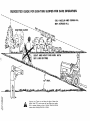
This unit is equipped with an internal
combustion
engine and should not be used on or near any unimproved
forest-covered, brush
covered or grass-covered
land unless the enginefs exhaust system is equipped with a spark arrester meeting applicable
local or state
laws (if any), If a spark arrester is used, it should be maintained
in effective working
order by the operator.
tn the State
of California
the
have similar
10009 ! M.,
laws,
laws apply
Federal
above
is required
on federal
by law
(Section
4442
lands,
See your
Authorized
-3-
of the
California
Service
Public
Center
Resources
for spark
Code)Ott_er
arrester
screen
states may
part
number
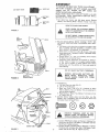
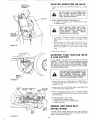
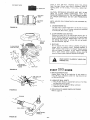
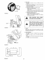
ASSEMBLY
CUT
AWAY
VENT
VIEW
To assemble and adjust your Tractor you will need:
two 7/16" wrenches, one 3/4" wrench, one 9/16"
wrench, one 1/2" wrench, one 3/4" socket, one
ratchet wrench and a utility knife
CAP
NOTE:
RIGHT HAND
(R.H.) AND LEFT HAND
(L.H.,) ARE
DETERMINED
FROM
OPERATOR'S
POSITION
WHILE
SEATED
ON THE TRACTOR
BATTERY
TUBE
1. Cut down
four
corners
and
Battery
and Steering
Wheel.
BATTERY
CELL
WEAR
EYE AND
fotd down carton,
Remove
Remove
Tractor
from skid.,
FACE
SHIELD..
WASH
HANDS
OR CLOTHING
IMMEDIATELY
IF ACCIDENTALLY
IN CONTACT
WITH E LECTROLYTE_
FIGURE 1
DO NOT SMOKE,
ED ELECTROLYTE
AIR
INTAKE
DUCT
FUMES
FROM CHARGARE EXPLOSIVE°
HOOD
2,
Flit and charge
Battery
(before
installing).
DETAILED
INSTRUCTIONS
PACKAGED
TERY
NOTE:
WITH
SEE
BAT-
a
Fitl Battery
with electrolyte
to bottoms of tubes in cells
(Fig 1), NOTE:
DO NOT OVERFILL.
OVERFILLING
WILL
RESULT
IN DAMAGE
TO TRACTOR
b, Check level of electrolyte
after 30 minutes.
Add additional electrolyte
if necessary° NOTE: TIGHTEN
VENT
CAPS SECURELY
c. Charge Battery
at a rate not exceeding
for about two and one half hours
d
amperes
Neutralize
excess electrolyte
for disposal
by adding
it
to four inches of water in a five gallon plastic contain,.
er, Stir with a wooden
or plastic paddle while adding
baking soda until the addition
of more soda causes no
more foaming
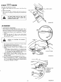
DO NOT
GRILL
FIGURE 2
three
SHORT
BATTERY
TERMINALS.
BEFORE
INSTALLING
BATTERY,WRISTREMOVE
METAL
BRACELETS,
WATCH
BANDS,
RINGS, ETC, FROM
YOUR PERSON,,
BATTERY
COMPARTMENT
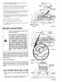
3,
Install
Battery
a
b,
Lift hood from rear sides (Fig
Lift out Air Intake Duct,
c
Make sure Drain Tube
(Fig
3) is fastened
to Drain
Hole in Battery
Tray and Battery
Tray is positioned
in
hole of Battery Support.
d, Place Battery
in Plastic
of Tractor)
(Fig, 3),
Tray
2)
(Battery
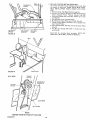
4. Connect
Battery
Cables using: two
Washers, two Lockwashers
and two
size below) found in Bag of Parts.
ER
Terminals
to front
Hex Bolts, two
Hex Nuts (shown
Flat
full
LOCKWASHER
HEX
BOLTS
POSITIVE
TERMINAL
MUST
BE CONNECTED
FIRST
TO PREVENT
SPARKS
FROM ACCIDENTAL
GROUNDING_
BLACK
(NEGATIVE)
CABLE
DRAIN
FIGURE
3
-4*
a
Connect
RED Battery
Cable to Positive (+) Battery Terminal with Hex Bolt, Flat Washer, Lockwasher
and Hex
Nut (Fig, 3) Tighten securely_
b,
Connect
BLACK
Ground
Terminal
with remaining
washer' and Hex Nut (Fig,
Cable to Negative (-) Battery
Hex Bolt, Flat Washer, Lock3),, Tighten securely,
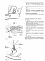
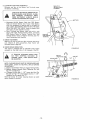
5. InstallBatteryusing:
two Int./EXtLockwashers,
twoWing
Nuts(shown
fullsizebelow)and
I NT./E X T,
LOCKWASHER
WING
NUT
WING
NUT
INT./EXT,
;KWASHER
_iiiii
ACCESS
DOO R
©
_'_I_II'_
TERMINAL
GUARD
TERMINAL
ACCESS DOOR
;ATTERY
two Battery
Bolts and one Terminal
Guard found in Bag of
Parts,
a. Using the slotted hole on one side of the Battery
Support
(Fig, 4) "insert one Battery
Bolt,
head of Bolt down,
Fasten the Battery
Bolt to the Terminal
Guard using
lntoiExt
Lockwasher
and Wing Nut as shown in Fig 4,
BOLT
BATTERY
SUPPORT
FIGURE
4
BATTERY
BOLT
/
SLOTTED
HOLE
b_
maining
tnt,/Ext.,
Lockwasher
and Wing Nut, Tighten
Wing Nuts securely by hand (Fig, 4).
NOTE:
USE TERMINAL
ACCESS DOORS (FIG, 4) FOR:
1., Inspection
2o
3.
4.
5.
for
secure connerJtions
(tighten
_ ./----"-_
1t2" HEX NUT
hardware).
Inspection
for corrosion_
Testing battery°
Jumping
(if required).
Charging (if required),
WHEN NOT IN USE, KEEP TERMINAL
ACCESS DOORS CLOSED°
.---_--STEERING
WHEEL
INSERT
COLUMN
64 Replace Air Intake Duct (Fig, 2)° Make sure bottom
Duct sits between battery and lip of Battery Tray
7.. Remove plastic on Tractor
Hood.
8. Close Hood.
9.
Install Steering Wheel.
NOTE:
POSITION
FRONT
a, Remove
1/2"
Hex Nut
WHEELS FORWARD°
and 2 = 1/4" Dia. Washer
Steering Colum0
(Fig° 5}.
b, Position
Steering
Wheel over Steering
c Secure Steering Wheel to Steering Column
Dia, Washer and Hex Nut (Fig, 5),
wt0.,
do Snap Steering
Steering Wheel
Install Seat_
lip of
FIGURE
5
from
Whe.el Insert°
using 2- 1/4"
Wheel Cap in place on Steering
Cap found in Bag of Parts..
SEAT
Wheel.
a, Mount
Seat Pivot Bracket
to Fender Strap Studs using
two Lock Nuts 3/8 - 16 (Fig
5A). Seat Pivot Bracket
and Lock Nuts found
in Bag of Parts, Tighten
Nuts
securely.
bo Mount Seat Pan to Seat Pivot Bracket using two Shoulder Bolts 5/16 - 18 and two Lock Nuts 5/t6 - 18 (Fig.
5A) (head of Bolts to outside)°
Bolts and Lock Nuts
found in Bag of Parts. Tighten
Bolts and Nuts securely,
SEAT PIVOT
BRACKET
SHOULDER
AND LOCK
SHOULDER
"" AND
LOCK
BOLT
\
/
-5-
BOLT
NUT
LOCK
NUTS
3/8,
16
FIGURE
5A
c
Place Seat on Seat Pan,, Screw 3/8"
Adjustment
Bolts,
Lockwashers
and Flat Washers into Seat (Fig, 6) Adjustment
Bolts, Lockwashms
and Ftat Washers found in
Bag of Parts, Tighten
finger tight,
SEAT
d. Place Seat in operating
position
Sit on the Seat an(_
press Clutch-Brake
Pedal all the way down. If operatin_
position is not comfortable,
adjust Seat,,
e Raise Seat,
Use 9/16"
wrench
to loosen Adjustment
T PAN
ADJUSTMENT
BOLTS
Bolts
ation
(Fig. 6), When
adjusted
for comfortable
tighten Adjustment
Bolts securely
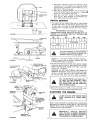
INITIAL
\
/
SERVICE
1. This engine has been shipped filled with oiIo Check Engine
Oil Level with Tractor
on level ground. Wipe Dipstick
(Fig.
7) clean, screw it in tight for' a few seconds, remove and
read Oil Level,, if necessary,
add OiD until "FULL"
mark is
reached.
RECOMMENDED
TEMPERATURE
CHANGE.
ALL
FIGURE 6
SAE
VISCOSITY
GRADES
RANGE
EXPECTED
BEFORE
NEXT OIL
OILS MUST MEET
A.P.I,, SERVICE
CLAS-
SIF1CATION SD, SE, OR SF.
-20o
0o
32 °
AIR
oper-
INTAKE
60 °
80 °
100 o
_1 Ilil
30 OR
:
.................
10W-30
:.........
"TT°wJ
i....
I
TO AVOID DAMAGE TO THE STARTING
SYSTEM, USE SAE 5W 30 OIL WHEN THE
TEMPERATURE
FALLS BELOW 32 °,
Capacity is 1 - 1/2 quarts, NOTE: DO NOT OVERFILL°
Dipstick assembly must be securely tightened into tube
at all times when engine is operating.
ENGINE
FIGURE
_\\
7
DIPSTICK
,, PARKING
BRAKE
"ENGAGED"
POSITION
"CLUTCH/BRAKE
POSITION
21
°'
Fill Fuel Tank (Fig, 6). Use fresh, clean, regular unieaded
automotive gasoline, (Use of leaded gasoline will increase
carbon and lead oxide deposits and reduce valve life).
Capacity is 3 - 1/2 gallonso
WARNING:
E_O NOT USE GASOHOL, METHANOL
OR
PREMIUM UNLEADED_ These type fuels react with water
content in the fuer and tend to form strong acids which
can corrode metal parts and harm rubber and p_astiCSo
CLUTCH!BRAKE
PEDAL
"CLUTCH"
POSITION
FILL TO BOTTOM OF GAS TANK FILLER NECK, DO NOT OVERFILL.
WIPE
OFF ANY SPILLED OIL OR FUEL. DO
NOT STORE, SPILL OR USE GASOLINE
NEAR AN OPEN FLAME.
FIGURE 8
LIGHT
SWITCH
{,
3.
THROTTLE
CONTROL
IGNITION
KEY
ATTACHMENT,
CLUTCH
LEVER
DISENGAGED"
POSITION
PARKING
BRAKE
\
GEAR SHIFT
CONTROL
LEVER
FIGURE 9
Reduce Tire
Tires,
CHOKE
pressure
to
14 PSI in front
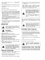
(Tires were overinflated
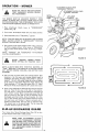
STARTING
THE
for shipping
and
12 PSI in rear
purposes),
ENGINE
LEARN TO START, STOP AND REVERSE
YOUR TRACTOR
IN A LARGE, OPEN
AREA_
NOTE: THIS TRACTOR IS EQUIPPED WITH INTERLOCK
SWITCHES TO PREVENT STARTING
OF THE TRACTOR
ENGINE WHILE THE ATTACHMENT
CLUTCH OR THE
TRACTOR CLUTCH IS ENGAGED.
IMMEDIATELY
THAT ARE NOT
ORDER. DO NOT
THE PURPOSE OF
REPLACE
SWITCHES
IN PROPER WORKING
ATTEMPT TO DEFEAT
THESE SWITCHES,,
1. Place
Attachment
position
Clutch
Lever
in
"DISENGAGED"
into
brake
4
(Fig., 9),
If ground
"F"
(fast}
travet is too slow, move Throttle
Control
to
position
or press Clutch-Brake
Pedal and shift
to a different
2,. Push Clutch-Brake
3., Place
Gear
Pedal
Shift
fully
Control
Lever
position
in "N"
neutral,
position
(Fig.
(Fig
start
NOTE:
BRING
TRACTOR
TO COMPLETE
STOP BEFORE
SHIFTING
GEARS
ALWAYS
SELECT
A
GROUND
TRAVEL
SPEED THAT WILL SUIT THE TERRAIN AND THE ATTACHMENT
BEING USED
posi _
tion
(Fig
9)o
4.
Pull
Choke
5
Move Throttle
6
Turn
Ignition
Key to "START"
position
until Engine starts
(Fig, 9). NOTE:
DO NOT
RUN STARTER
CONTINUOUSLY
FOR
MORE
THAN
FIFTEEN
SECONDS
PER
out (Fig
9),
Control
to middle
9).
NEVER
PLACE
YOUR
HANDS
OR FEET
IN OR UNDER
ANY POWERED
ATTACHMENT
OR NEAR
ANY
MOVING
PART
WHILE
TRACTOR
OR ANY
POWERED
ATTACHMENT
IS RUNNING
MINUTE.
If engine does not start after several attempts,
move Throttle
Control
to "F"
(fast} position,
wait a few
minutes
and try
DO NOT OPERATE
THE
OUT
THE
DISCHARGE
PLACE,
again.
The first time you start the engine, it will take extra cranking time to move fuel from tank to the engine.
NOTE:
ALLOW
ENGINE
TO WARM
UP FOR A FEW
MINUTES
BEFORE
OR ATTACHMENT,
7,,
ENGAGING
When restarting
a warm engine,
way between
"S"
(slow} and
may not
gear
B)_
CLUTCH
OF TRACTOR
NOTE: A SPARK ARRESTER
MUFFLER
(PAGE 28) IS
AVAILABLE
AS AN ACCESSORY
PART FOR YOUR
TRACTOR.
CHECK LEGAL
REQUIREMENTS
IN YOUR
AREA.
move Throttle
Control
mid"F"
(fast} position.
Choke
have to be used.
NEVER
OPERATION
RUN
AND
STOPPING
CAUTION
TO AVOID
1
INJURY
1. Read owners manual
2, Know location
and function
3. Keep guards, safety shields
ingo
4, Remove objects that can be
5. Do not mow when children
3
thrown
by blades,
and others are around.
tQ.
Be sure blades and engine
hands or feet near the blades,
11.
Remove
key when
leaving
have
stopped
before
LIP OF BATTERY
YOUR
Push Clutch-Brake
Pedal
Move Shift
4. Place
tion_
Control
Attachment
slowly
5, Move Throttle
placing
6, Turn
WEIGHT
full
"BRAKE"
position
ignition
to "NEUTRAL"
Clutch
Control
Lever
in "DISENGAGED"
to "S" (slow)
Key to "OFF"
position.
posi-
position,
position,
TRANSPORTING
mid.
2. Push Clutch-Brake Pedal down firmly (Fig. 8)° Move Gear
Shift Control Lever to desired gear (Fig, 9}°
Pedal
SLOWLY
to
start
YOUR
For pushing or towing your tractor,
Lever to
N neutral
poslt_on
(Fig.
YOUR
TRACTOR
FASTER
THAN
OPERATION
1o With engine running and warm, place Throttle
Control
way between
"S" (slow) and "F" (fast) position
PREVENT
KEY WHEN
UNAUTHORIZED
LEAVING
TRAC-
TO
OPTIONAL
WHEELOTHER
WEIGHTS,
THE
TRACTOR
THAN EXCESTHE
SIVE WEIGHT MAY OVERLOAD
AND
DAMAGE THE TRANSMISSION.
Clutch-Brake
TRAY,
machine
DO NOT ADD ADDITIONAL
Release
WITHOUT
TRACTOR
into
Lever
TOR
TO
REMOVE
USE.
3,
ENGINE
DUCT INSTALLED
(FIG. 7)
BOTTOM
LiP OF AIR
iN_
SITS BETWEEN
BATTERY
2_ Place Parking Brake Lever in "ENGAGED
I' position
and release pressure from Clutch-Brake.
Pedal should
remain in
brake position,.
NOTE:
MAKE
SURE PARKING
BRAKE
WILL HOLD TRACTOR
SECURE,
of all controls,
and switches in place and work-
Never carry children or passengers,
Always look behind machine before backing,
Do not mow where machine can tip or slip,
If machine
stops going uphill,
stop blade and back
down.
TRACTOR
THE
AIR INTAKE
MAKE
SURE
TAKE
DUCT
BEFORE DRIVING
THE TRACTOR,
INSTALL
MOWER OR REMOVE MOWER
PARALLEL
LINK (FIG. tl).
6,
7o
8,
9.
MOWER
W1THGUARD
1N
movement.
-7-
TRACTOR
place Gear Shift Control
9), NOTE: DO NOT TOW
SIX MILES
PER HOUR.
TRACTOR
NEGATIVE
(BLACK
CABLE)
TERMINAL
1
Choose
hills.
OPERATION
the
lowest
DO
gear
NOT
ON
BEFORE
DRIVE
HILLS
starting
UP
OR
up
or
DOWN
down
HILLS
AND
WITH
DO
SLOPES
NOT GREATER
DRIVE
ACROSS
THAN
SLOPE.. REFER TO PAGE 47.
ANY
15 ° ,
BATTERY
2. AVOID
a
STOPPING
OR SHIFTING
if slowing
is necessary,
to middle position,
ON HILLS
move" Throttle
Controt
Lever
LEAVE
ENOUGH
ROOM
WHEN
STOP.
PING
AND
STARTING
TO
ALLOW
SLIGHT
TRACTOR
ROLL DOWNHILL
AS
CLUTCH-BRAKE
PEDAL
MOVES
THROUGH
CLUTCH
POSITION..
POSITIVE
(RED CABLE)
TERMINAL
b, If stopping
is absolutely
Pedal quickly
to brake
Brake
l
necessary,
push Cfutch-Brake
position
and engage Parking
c. After
starting
your tractor,
make sure tractor
is in 1st
gear and that you have allowed
room to roll slightly
downhill.
Disengage
Parking
Brake and release Clutch8rake Pedal SLOWLY
to start tractor
forward
move-
FIGURE 10
merit
3.
Make all turns
graduaNy
STARTING
YOUR
A LOW BATTERY
TRACTOR
WOTH
If your' Battery
is too low to start the engine, it should be
recharged.
If
Jumper Cables
are used for' emergency
starting
follow
this procedure:
NOTE:
YOUR TRACTOR
iS EQUIPPED WITH A 12 VOLT
NEGATIVE
GROUNDED
SYSTEM,
THE OTHER
VEHICLE
MUST ALSO BE A 12 VOLT
NEGATIVE GROUNDED
SYSTEM°
LEAD-ACID BATTERIES GENERATE EXPLOSIVE GASES. KEEP SPARKS, FLAME,
AND
SMOKING
MATERIALS
AWAY
FROM BATTERIES, ALWAYS WEAR EYE
PROTECTION AROUND BATTERIES.
MOWER
PARALLEL
LINK
FIGURE
1t
Connect
each end of the
terminals
of
chassis) (Fig
CLUTCH
ROD
RETAINER
SPRING
PARAI,LEL
LINK
FRONT
AXLE
REAR
HINGE
PIN
FIGURE
FRONT
HINGE
PIN
cable
(taking
to the
care not
Connect
one end of the BLACK
cable
(-) terminal
of fully charged battery,
3_
Connect
the other
or good CHASSIS
Tank or Battery)
4,
J
RED
2,
RETAINER
SPRINGS
CLUTCH
each battery
10),
Disconnect
end of the cable to
GROUND
on tractor
(+)
against
the NEGATIVE
ENGINE
(away
BLOCK
from Gas
cables in reverse order:
a Engine Block or chassis of tractor.
b, Negative terminal
of fully charged
c_ Positive termina[so
MOWER
to
POSITIVE
to short
AND
DRIVE
battery
BELT
INSTALLATION
Your
38"
Mower
instalts without
the use of tools,,
Lever (Fig_ 15) to its highest position,
Knob to lowest position
(Fig 14},
12
-8-
Turn
Depth
Raise
Lift
Adjustment
t.
Install Front Hinge Pin through Axle
! 2). Secure with Retainer Spring,
2, install
Rear
Parallet
13, install
Hinge
Link (Fig,
Clutch
Rod
Pin through
Mower
12),, Secure with
in Clutch
and Parallel
Lift
Retainer
Link
(Fig,
Brackets
and
CLUTCH
LEVER
ROD
Spring,
Lever (Fig., 13 - inset).
SUSPENSION
4, Move Lift
Lever (Fig° 15) forward
Arms,, Slide Trunnions
through
Lift
cure with Retainer Springs (Fig. 13)
5
Roll
Belt
RETAINER
SPRING
to lower Suspension
Bracket holes and se_
Belt over Mower Drive Pulley,, Make sure Belt is inside
Guides (Fig, t4)o See Belt Drive Schematic
Decal on
Mower
Housing,,
6. Use Lift Lever (Fig° 15) to raise mower
NOTE', SEE MOWER ADJUSTMENT,
7., Turn Depth Adjustment
dle of it's travel°
Knob
BELOW
clockwise
(/"'_}
to tile midRETAINER
SPRING
LIFT
BRACKET
TRUNNION
MOWER
FIGURE
13
ADJUSTMENT
FOR ANY ADJUSTMENTS,
OR MAINTENANCE:
INSPECTION
\
PUSH
TRACTOR
CLUTCH-BRAKE
PEDAL
COMPLETELY
INTO
BRAKE
POSITION,,
MOVE
GEAR
SHIFT
LEVER
TO
"'N"
ING
\
NEUTRAL
POSITION.
PLACE PARKBRAKE
IN "ENGAGED"
POSITION,,
tN
POSITRON.
SHUT
PLACE "ENGAGED"
ATTACHMENT
CLUTCH
LEVER
OFF THE ENGINE,,
MAKE ABSOLUTELY
SURE THE BLADES
AND ALL
MOVING
PARTS
HAVE
COMPLETELY
STOPPED,
REMOVE
THE IGNITION
KEY, DISCONNECT
THE SPARK
PLUG WIRES
FROM
THE
SPARK
PLUGS AND
KEEP WIRES
AWAY
FROM THE PLUGS TO PREVENT
INJURY
FROM
ACCIDENTAL
STARTINGo
FIGURE 14
NOTE: BEFORE CHECKING THE SIDE TO SIDE AND
FRONT TO REAR ADJUSTMENTS, PAGES 9 AND 10, BE
SURE PRESSURE IN FRONT TIRES IS 14 PSI AND PRESSURE IN REAR TIRES IS 12 PS1, IF TIRESARE OVER OR
UNDER INFLATED
YOU WILL NOT PROPERLY ADJUST
YOUR MOWER,
D EPTH ADJUSTM ENT
LIFT LEVER
PLUNGER
Adjustment
for mower height is made with the Depth
ment Knob°
Raise Mower cutting
height
by turning
Adjustment
height by
LEVEL
Knob
turning
clockwise
( /'_
Depth Adjustment
MOWER
FROM
AdjustDepth
LIFT
LEVER
)o Lower Mower cutting
Knob counterclockwise
SIDE
TO
SIDE-TO-SIDE
'ADJUSTMENT
,,
SIDE
TOP OF
In Park tractor
on level surface
Depress Lift
Lever
and use Lift
Lever to raise mower to maximum
Plunger
cutting
height
2., Measure height of Top of Flange to level surface at front
.
It
I_
mower. D_stance
A should be the same (Fig. 15).
of
-9-
FIGURE
15
3,
If distance t'A" needs to be changed, snap out Access Hole
Cover on LH
side above Footrest_ Use 9/t6"
wrench on
Nuts "B" and "C" at Side-To-Side
Adjustment
Trunnion
(Fig° 16)..
4.
To raise left
Nut UC"
5,=
To lower left side of mower, loosen Nut "C" and tighten
Nut t'B",
NOTE: ONE ROTATION
OF ADJUSTMENT
NUTS IS
EQUIVALENT
TO APPROXIMATELY
3/161' HEIGHT
CHANGE,
.
SIDE*TO-SIDE
ADJUSTMENT
_.
TRUNNION
_'_
NUT
ii
FIGURE
n
'
i
"B"
r
side
of
mower,
loosen
Be sure atl Nuts are securely tightened.
NOTE: SEE MOWER ADJUSTMENT,
BELOW,
Nut
_B"
and
tighten
FRONT-TO-REAR,
i
ADJUST
MOWER
TO REAR
16
FROM
FRONT
1. To obtain the best cutting resufts, your Mower Housing
should be adjusted so the Front and Rear Flange distance
='D_ (Fig, 17) is 5/16" lower in front when the mower is
positioned in the highest cutting position.
NOTE: MEASURE DISTANCE _ID" FROM SURFACE TO
RIGHT REAR FLANGE AND COMPARE TO DISTANCE
"D" ON RIGHT FRONT FLANGE_
REAR
SUSPENSION
ARM
2,
To raise rear of mower,
loosen Nut "E" on both Rear Suspension Arms. Screw both Nuts "F" up EQUAL
NUMBER
OF TURNS {Fig. 18).
3_
When distance "D"
en Nut "E"
is 5/16"
lower at front than rear, tight-
4. To lower rear of mower, loosen Nut '_F" on both Rear
Suspension Arms an EQUAL NUMBER OF TURNS (Fig_
L1 FT
BRACKET
18)_
FRONT
FLANGE
5, When distance "D u is 5/16" lower- at front than rear, re_
tighten Nuts t_E".
NOTE: WHEN ADJUSTING
REAR SUSPENSION TRUNNIONS, ALWAYS ADJUST BOTH EQUALLY
SO MOWER
WILL STAY LEVEL,
REAR
SUSPENSION
TRUNNION
FIGURE
17
REAR
SUSPENSION
ARM
REAR
LIFT
TRUNNION
NUT
FIGURE 18
- 10-
OPERATION
- MOWER
ATTACHMENT
"DISENGAGED"
READ
THE "RULES
TION"
CAREFULLY
ING YOUR MOWER,
FOR SAFE OPERABEFORE
OPERAT-
ATTACHMENT
"ENGAGED"
DEPTH
ADJUSTMENT
KNOB
THE MOWER MUST BE ADJUSTED PROPERLY FROM
FRONT TO REAR AND LEVELED FROM SIDE TO SIDE
BEFORE OPERATING. THIS IS NECESSARY FOR LEVEL
AND EFFICIENT MOWING REFER TO PAGES9&
10,
1. Place Attachment
position (Fig,, 19),
2. Push tractor
Clutch
Clutch-Brake
Lever
in
CLUTCH
LEVER
POSITION
CLUTCH
POSITION
LIFT LEVER
R
"DISENGAGED"
LEVER
LIFT
[.EVER
"LOWEST"
POSITION
Pedal fully into brake position.
3, Place Gear Shift Lever in *'NEUTRAL"
position
NOTE: TRACTOR MUST BE IN NEUTRAL AND ATTACHMENT CLUTCH
LEVER IN HDISENGAGED"
POSITION
BEFORE TRACTOR WILL START,,
4, Start tractor and set engine speed to about 1/3 to t/2 throttle before engaging mower, After mower is _'ENGAGED"
and you have started forward travel, set to FULL THROTTLE,
NOTE:
"ENGAGE"
OR I_DISENGAGE'_ ATTACHMENT
CLUTCH LEVER SLOWLY,
GUARD
FIGURE t9
NEVER
WHEN
"ENGAGE" ON
SITTING
MOWER
TRACTOR
EXCEPT
SEAT,
f f
NOTE: ALWAYS
MOW WITH THROTTLE
CONTROL IN
"FAST" POSITION. THIS RESULTS IN BETTER GRASS
CUT, BETTER ENGINE COOLING, AND BETTER FUEL
ECONOMY.
=.
5. Use Lift Lever to lower mower
into cutting
position
Start
mowing
in the first
gear and increase ground
speed as
conditions
will permit,
Average cutting
height
is approximately 2- 1/2 to 2- 3/4 inches, Height of cut can be adjusted by means of the Depth Adjustment
Knob, Moving the
Knob clockwise
(/'_'_,)
raises the mower (Fig, t4 - Inset),
Moving the Knob counterclockwise
(F'_) lowers the mower.
FIGURE 20
6. Drive so that clippings
are discharged
onto the area that has
been cut. Have the cut area to the right of the machine°
This wil! result in a more even distribution
of clippings
and
more uniform
cutting,
When mowing
large areas (Fig, 20)
start by turning
to the right so that the clippings
will be
discharged
away from shrubs, fences, driveways,
etc After
two or three rounds, mow in the opposite
direction
making
left hand turns until finished,
If grass is extremely
tall, it
should be mowed twice. The first time cut relatively
high.
The second time to the desired height
The left hand side
of mower should be used for trimming
FLIP=UP
DISCHARGE
GUARD
Your mower has a flip.up
Discharge Guard (Fig.
or gate clearance when held in raised position,
19) lot
dool
7
MAKE
SURE
ATTACHMENT
CLUTCH
LEVER
tS IN "DISENGAGED"
POSITION
AND BLADES
HAVE
STOPPED
BEFORE
RAISING
DISCHARGE
GUARD
(DEFLECTOR)., NEVER
OPERATE
MOWER WITHOUT DISCHARGE
GUARD
tN OPERAT.,
ING POSITION.
|
1
1'1"
£L
ASSEMBLY
1. When grinding,
care should be taken to maintain
blade balance and the blade should be checked for proper balance
before reinstallation
on mower, Unbalanced
or bent blade
will cause excessive vibration
when running,
and eventual
damage to mower or engine
Replace bent, damaged or unbalanced blades.
To check Blade balance, drive a nail into a beam or wall.
Leave about one inch of the straight nail exposed, Place
Center Hole of clean Blade over the head of the nail (Fig.
22). NOTE: CENTER HOLE OF BLADE ON NAIL,, tF
BLADE IS PROPERLY BALANCED,
BLADE SHOULD
REMAIN IN POSITION SHOWN IN FIG. 22, IF EITHER
END OF THE BLADE MOVES DOWNWARD, BLADE IS
NOT BALANCED AND MUST BE REPLACED.
FLANGES
I
BLADE
WASHER
.
LOCKWASHER_
HEX BOLTGR5_-_
FIGURE
21
To ensure satisfactory
operation r it is recommended
that
before the start of each mowing
season, the old blades be
discarded
and replaced with new blades, Mower blades can
be purchased
at any Sears Service Center/Departments
and
most Sears Retail Stores
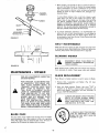
DAI LY
MAI
NTENANCE
Make sure all nuts on bolts are tight and cotter pins and retainer springs are secure= Keep blades sharp, Observe atl safety precautions.
K_ep mower well lubricated
(refer to page 22),
¸¸¸
CLEANING
MOWER
DISCONNECT
SPARK
PREVENT
ACCIDENTAL
FORE CLEANING.
FIGURE
MAINTENANCE
INSPECTION
PUSH TRACTOR
CLUTCH-BRAKE
PEDAL COMPLETELY
INTO BRAKE POSITION,
PLACE
bARKING
BRAKE
IN
"ENGAGED"
POSITION.
MOVE GEAR
SHIFT LEVER
TO "NEUTRAL"
POSITION,
PLACE ATTACHMENT
CLUTCH
LEVER
IN "DISENGAGED"
POSITION,
TURN
IGNITION
KEY TO OFF POSITION. F/lAKE ABSOLUTELY
SURE THE
BLADES
AND
ALL
MOVING
PARTS
HAVE
COMPLETELY
STOPPED.
REMOVE
THE IGNITION
KEY, DISCONNECT THE SPARK PLUG WIRES FROM
THE SPARK PLUGS AND KEEP WIRES
AWAY FROM THE PLUGS TO PREVENT
INJURY FROM ACCIDENTAL
STARTING,
CAR
E
For best results mower blades must be kept sharp The blades
can be sharpened
with a few strokes of a file or on a grinding
wheel° We suggest they be sharpened after every 15 hours of
Do not attempt
from a garden hose will remove
of mower.
Clean mower
after
fresh clippings
each mowing_
= MOWER
FOR ANY ADJUSTMENTS,
OR MAINTENANCE:
mowing,.
TO
BE-
22
Water pressure
from underside
BLADE
PLUG
WIRES
STARTING
to sharpen while
on mower_
BLADE
Raise
t.
Mower
REPLACEMENT
to
highest
Remove
Bolt,
counterclockwise
position
Lockwasher
(f-X),
to
and
permit
Washer
access to Blades.
(Fig
21)
(turn
2. Place new Blade between
Flanges,
(the word
"TOP"
is
stamped
on all Blades to assure proper
installation),
and
secure with
Washer,
Lockwasher
and Bolt previously
removed. TIGHTEN
SECUR ELY.
ALWAYS
USE GRADE
5 HEAT TREATED
BOLTS
TO ATTACH
BLADES_
CHECK
BOLTS
IN BLADES
OCCASIONALLY
TO
MAKE
SURE
BOLTS
ARE TIGHT.
QUE BOLTS 30 - 35 FT. LBS.
TOR-
A GRADE
5 HEAT TREATED
BOLT
CAN
BE IDENTIFIED
BY THREE
LINES
ON
THE
BOLT
HEAD
AS
SHOWN AT LEFT,
MOWER
BELT
ADJUSTMENT
Your tractor has been manufactured with the abiNty to re-adjust mower drive belt to provide you with longer belt life,
/I"
ATTACHMENT
CLUTCH
LEVER "DISENGAGED"
/
POSITION
/_._._ES/T'7>OSITtON
DEPTH
)If the Attachment Clutch Lever (Fig, 23) travels 3- 1/2" up
the slot in the dash before spring tension resistance is evident,
adjustment
is necessary. NOTE: CHECK FOR PROPER
SPRING TENSION WITH ENGINE OFF AND LIFT LEVER
IN HIGHEST POSITION,
_1
1_"_
t_,_,_._
I...,_tL'L_/_/q
1, Remove
mowel
2, Remove
Cotter
Assembly
(Fig,
deck
Pins
from
t
"LOWEST"
_
,pOSITION
tractor,
from
both
sides
of
the
Rock
Shaft
24)
3, Loosen the 4 Locknuts on the EH, and L, Ho Pivot Brackets
(Fig, 24) only until Rock Shaft Assembly can be removed.,
4. Remove Rock Shaft Assembly from R,H, and L..H, Pivot
Brackets, NOTE; DO NOT DISASSEMBLE BRAKE ROD,
ENGINE
!'°,LL
PULLEY
5,, Remove Extension
Spring from lower hole (original
position) in Rock Shaft Assembly
and insert in upper hole in
Rock Shaft Assembly
(Fig 24- Inset),
GUIDE
L,H, MANDREL
6, Replace Rock Shaft Assembly between R,H and L.H Pivot
Brackets
7, Tighten Locknuts securely making sure Carriage Bolts are
seated in square holes of mower housing,
8, Replace Cotter Pins on both sides of Rock Shaft Assembly.
NOTE: WHEN INSTALLING
A NEW BELT, EXTENSION
SPRING MUST BE RETURNED TO LOWER HOLE (ORIGINAL POSITION) ON ROCK SHAFT ASSEMBLY,
TO
REMOVE
MOWER
PiN
COTT
LOWER HOLE
(ORIGINAL
POSITION)
BELT
REPLACE
MANUAL:.
ONLY
DECAL
Lever
HOLE%
R.H.
LOCATED
PIVOT
ET
IN THIS
ROD
BRAKE
I
Clutch
24
EXTEN5
SPRING
WITH THE BELTS SPECIFIED
1_, Place Attachment
position (Fig" 23),
RH, MANDREL
FIGURE
uPPER
NOTE: MOWER BELT INSTALLATION
ON MOWER HOUSING,
ER
SPRING
in
"DISENGAGED"
2. Turn Depth Adjustment
Knob to lowest position. Move
Mower Lift Lever (Fig. 23) forward to lower Mower to its
lowest position.
L.H.
BRACKET
\
LOCI(NtJT
LOCKNUTS
I"
3. Rofl Belt off Engine Pulley (Fig° 24).
RETAINER
SPRINGS
4o Pul! Belt off both Mandrels (Fig, 24)
5, Spring Belt Guide away from
,off Idler Pulley.
R,H,
SUSPENSION
ARM
Idler Pulley and pull Belt
RETAINER
SPRINGS
6,,,,SNde Belt from under Idler Spring,
TO
REPLACE
MOWER
BELT
1., Slide Belt under Idler Spring (Fig,. 24),,
2. Place Belt on rear side of both Mandrels,
3. Spring Idler Belt Guide down and place Belt around rear
side of Idler Pulley,
4, Roll Belt over Engine Pulteyo
HINGE
REAR
SUSPENSION
TRUNNIONS
PINS
CLUTCH
ROD
LIFT
BRACKET
FIGURE 25
STORAGE
When mower
is to
thoroughly,
remove
be stored
for a period of time.
clean it
al! dirt, grease, leaves, etc. Give blades
and underside
of housing a good coat
ventative= Sl_ore in a clean dry area
of
grease
or rust
pre-
TRACTOR
MAINTENANCE
INSTRUCTIONS
\
To
keep
essary
ENGINE OIL
DiPSTiCK
AND FILL TUBE
your
service
tractor
using
running
the
better,
following
longer;
DISCONNECT
SPARK
PREVENT
ACCIDENTAL
FIGURE
27
FORE
MAKING
JUSTMENT
OR
BURETOR),.
FIRST
_
1. CHANGE
Changing
breakqn
ANY
INSPECTION,
REPAIR
(EXCEPT
REMOVE
ADCAR-
HOURS
ENGINE
OIL
Oil
the
after
residue
which
first
might
two
hours
will
be damaging
help eliminate
to your
Engine.
DIRT TO ENTER
MOWER
1,, Remove rmower Belt
Mower Belt", through
per instructions
step 3,
under
"To
2. Turn Depth Adjustment
Knob to lowest position
Lever to lower mower to its lowest position
Remove
Use Lift
4. Pull Retainer Springs out of Rear Suspension Trunnions
Remove Rear Suspension Trunnions from Lift Brackets
(Fig. 25)
5 Pull Retainer Spring out of Rear Hinge Pin Remove Rear
Hinge Pin (Fig 25)
Poll Retainer Spring out of Front Hinge Pin Remove Front
Hinge Pin (Fig 25)_
raise Suspension
Arms.
Slide
DAILY
CHECK
OR
ENGINE
EVERY
OIL
HOURS
LEVEL
!
3. Remove Retainer' Spring from Clutch Rod; pull Clutch Rod
out of Clutch Bracket.
7. Use Lift Lever to
from under tractor
TO
BE-
a. Drain Oil with Engine warm, Loosen Oil Drain Plug Wing
Nut (Fig, 28) and remove Dipstick
Catch Oil in a suit
able container
Tighten Oil Drain Plug Wing Nut_
b Refill
Engine Oil
(See chart,
page 6) Refill capacity
ix 1 - 1/2 quarts
NOTE:
DO NOT OVERFILL
Replace Dipstick
FIGURE 28
6
nec-
ScheduleQ
PLUG
WIRES
STARTING
NOTE: BE CAREFUL NOT TO ALLOW
THE ENGINE WHEN CHANGING OIL
TO
perform
Maintenance
mower
out
NOTE: IF AN ATTACHMENT
OTHER THAN THE MOWER
DECK IS TO BE MOUNTED ON THE TRACTOR, THE LH
AND RH
SUSPENSION ARMS (FIG
25) SHOULD BE
REMOVED FROM TRACTOR
WITH
DO
NOT
ENGINE
CHECK
RUNNING
ENGINE
OIL
LEVEL
Several minutes after stopping
Engine, check Engine Oil Level
with
Tractor
on level ground
Wipe Dipstick
(Fig
27) clean,
screw it down tight for a few seconds,
remove and read Oil
Level. If necessary, add Oil until
"FULL"
mark is reached.
(See chart, page 6} NOTE: DO NOT OVERFILL
t
t
.ouRs
(_,.,,._KNOB
(EVERY
15 HOURS
IN VERY
!1
DUSTY
CLEAN
Air
AIR
Screen
IF OPERATING
CONDITIONS)
SCREEN
(Fig,
29)
must
allow
free.,ftow
of
air to prevent
Engine damage from overheating.
Clean with a wire
compressed
air or water
pressure
to remove
dirt,
stubborn
dried
CLEAN
FRONT
brush,
chaff,
gum and fibers_
PLATE
2,
GRILL
The front Grill (Fig 30) must allow
vent engine damage from overheating
a Brush off debris
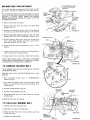
3o LUBRICATE
STEERING
There is a grease fitting
free flow
of air to
pre-
AND FRONT WHEELS
on each front wheel
Use a grease
FOAM
PRE*CLEANER
gun; give each grease fitting
two shots of Extreme Pressure
Lubricating
Grease Amdex
No. 1 or equivalent
(available
through
your Sears Service Center),
Use 30 weight
oil to
lubricate
Front
Spindles
(Fig, 31)
Use 30 weight
oil to
lubricate
Front Axle Pivot (Fig, 31)
4, OIL
PIVOT
POINTS
Place several drops of SA E 30 Oil at points
move against each other, especially:
a Front Axle Pivot,
b Hood Hinges
c. Foot Pedal Shaft (both
d Lift Shaft (both ends)
SEE LUBRICATION
5, CHECK
'ER
CARTRIDGE
where
parts
BODY
ends)
CHART,
PAGE
22
FIGURE
29
BATTERY
a,
Electrolyte
solution
level in each Battery
Celt should be
even with bottoms
of tubes in cells (Fig. 32), Add distilled water if necessary
NOTE:
DO NOT OVERFILL
b, Keep Battery and Terminals
clean, Refer to step 6_
c, Keep Battery
Bolts tight.
d, Keep Vent
Caps tight
and small vent holes
open.
e, Recharge SLOWLY
at 3 amperes if necessary
6. CLEAN
BATTERY
AND
in
Caps
TERMINALS
Corrosion
and dirt on the Battery
and Terminals
cause
the Battery
to "leak"
power and hinders the operation
of
the charger,
a, Remove
the Battery
from
the Tractor
and wash with
GRILL
four tablespoons
of baking soda to one gallon of water
NOTE:
BE CAREFUL
NOT
'tO
GET
THE
SODA
b
SOLUTION
INTO THE CELLS.
Rinse the Battery
plain water, dry and reinstall on Tractor°
Clean terminals
and cable ends with a wire brush
bright,
Replace
Battery
tions with Vasoline
Cables,
Coat
terminal
with
until
FIGURE 30
connec-
GREASE
BOTH
Ev .v 5® .ou..
(OPERATING
IN
MORE FREQUENT
DUSTY
CONDITIONS
SERVICING)
MAY
REQUIRE
b1_ CLEAN AIR CLEANER
FOAM PRE-CLEANER
(FIG 29)
a. Remove Knob and Cover,
b Remove Foam Pre..Cleaner
element
by sliding it off of
the Paper Cartridge.
c, Wash Foam Pre_Cleaner
in liquid
detergent
and water,
d Wrap Foam Pre-Cteaner in cloth and squeeze dry,
e., Saturate
Foam Pre-Cleaner
in engine oil, Squeeze to remove excess oil.
f,
Install
Foam
Pre-Cleaner
ble Cover and Screw
down
over Paper Cartridge.
tight
OIL SPINDLES
Reassem
- 15 -
FIGURE 3]
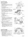
CUT-AWAY
Yearty
or every 100 hours,
whichever
occurs first,
remove
Paper Cartridge
(Service more often if necessary)= Clean by
tapping
gentry
on flat
surface,
if very dirty,
replace Cartridge.
VIEW
NT
CAP
CAUTION:
PETROLEUM
SOLVENTS
ARE NOT TO BE
USED TO CLEAN
PAPER CARTRIDGE,
THEY MAY
CAUSE DETERIORATION
OF THE CARTRIDGE. DO NOT
OIL PAPER CARTRIDGE,
DO NOT USE PRESSURIZED
AIR,
BATTERY
TUBE
BATTERY
CELL
NOTE: NEVER
MOVED,
,
FIGURE 32
RUN ENGINE
CHANGE
ENGINE
The
time
best
WITH
AIR
CLEANER
OIL
to drain
Engine
Oil
is at the end of
operation
when all dirt and foreign materials
in the hot Oit, See oil char% page 6,
3_
CLEAN
ENGINE
Remove
any
COOLING
dust,
dirt
FINS
or oil from
Engine
Cooling
Fins to
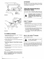
MUFFLER
_,f
Do not operate the tractor
without a Muffler
{Fig. 33) or
tamper
with
the exhaust
system,
Damaged
Mufflers
or
spark arresters could create a fi_e hazard. Inspect periodi*
catly and replace if necessary
If your engine is equipped
with
a spark attester
screen assembly,
remove
every 50
hours for cleaning and inspection.
Replace if damaged,
CLEAN ENGINE
COOLING FINS
WEAR SAFETY
PRESSED AIR_
AIR GUIDE
COVER (BOTH
SIDES)
\
GLASSES IF USING COM-
MUFFLER
,=v,=.v
FIGURE 33
1., REPLACE
.ou.s
SPARK
PLUGS
Replace Spark Plugs at the beginning
every !00 hours, whichever
comes first
at 030 inch (Fig, 34},
030" FEELER
GAUGE
2_
LUBR ICATE BALL JOIN1"S
a Move Rubber Boots to expose
and Steering Link (Fig,. 35},
b. Coat Ball Joints with Silicone
SPARK
PLUG
c
3.
FIGURE 34
ROD
BALL
FRONT
WHEEL
SPINDLE
FIGURE 35
a day's
are suspended
prevent Engine damage from overheating.
Air Guide Covers
must be removed
(Fig, 33)
Remove eight 7/16"
bolts and
five phillips
head screws to remove
side and top covers,
See Hood Removal, page 20_
TOP AIR
GUIDE
COVE R
TIE
RE-
- 16-
Reposition
Rubbm
REPLACE
AIR
Refer to
page t5,
Bail
Spray
of each season or
Gap should be set
Joints
Lubricant
Boots,
CLEANER
PAPER
CARTRIDGE
on Tie
Rods
REPLACE
ao Remove
36),,
IN-LtNE
Hose
FUEL
Clamps
FILTER
from
Fuel
bo Remove Fuel Filter,
c, Ptace new Fuel Filter in position
side of FPter in direction
of Fuel
Lines
at Fuel
Filter
(Fig.
HOSE CLAMPS
FUEL
with fuel line (arrow on
Filter) and reinstall Hose
Clamps.
BE SURE THERE ARE NO FUEL LINE
LEAKS AND THAT HOSE CLAMPS ARE
PROPERLY INSTALLED°
FIGURE
36
As NEEOEa
1. CARBURETOR
ADJUSTMENT
Never attempt
to change maximum
preset at the factory
and should only
engine speed This is
be changed by a quali-
fied service technician who has the necessary
a, Move Throttle
Control
(on the dashboard)
b
position.
Check that two holes "A"
Screw and adjust Throttle
line up (Fig° 37 _ Inset).
REFER
TO
PAGE 6,,
equipment
to "SLOW
Hold
Governor
Control
Mixture
Screw clockwise
to slow (Fig, 38),
g, Turn Mixture
ho Move Throttle
or dies, turn
'_
line up, If not, loosen Clamp
Cable until the two holes do
"STARTING
THE
ENGINE",
c, Start Engine and allow to warm for five minutes°
final adjustments
with engine running,
do High Speed is fixed, no adjustment
is possible,
e,, Adjust
Carburetor
Mixture
Screw to suggested
setting.
-- Turn
Mixture
Screw clockwise
(('_'_)
closing
tight ONLY,
and then turn counterclockwise
1 - t/2 turns
(Fig. 38), CAUTION:
VALVE
BE DAMAGED
IF TURNED
IN TOO FAR°
f,
THROTTLE
CABLE
HOLES
"'A'"
Make
initial
finger
(t-'n)
MAY
THROTTLECABLE
against Throttle
Stop° Turn
(/_)
untii engine just starts
FIGURE 37
Screw counterclockwise
(1(_) 1/2 turn,
Control
to "FAST",
If engine hesitates
Mixture
Screw
1/4 turn counterclockwise
(F-"x)
until engine will accelerate
as Throttle
÷
_1
I1
It
II
Is moved from
SLOW
to
FAST
,
Control
THROTTLE
STOP
SCREW
GOVERNOR
CONTROL
- 17 -
FIGURE
38
2,.
GUIDE
TRANSAXLE
PULLEY
REPLACE
The tractor
TRACTOR
Drive
MOTION
Belt may
the tractor
on level
BELT
INSTALLATION
R EST,
area.
DRIVE
BELT
be replaced
without
Engage Parking
DECAL
UNDER
tools, Park
Brake,
LEFT
NOTE:
FOOT-
a
b,
Remove mower, (See Mower Section,
page 13),
Remove two Retainer
Springs from Belt Guide Bracket
below
Transaxte
Pulley,
Remove
Bracket
(Fig° 39},
c, Swing Belt Guides away from Belt, toward
rear of trac_
tot (Fig,, 39)°
d. Rotl Belt over top of Transaxte
Pulley.
e= Roll Belt over Engine Pulley and off Idler (Fig. 4i)
f. Release Parking Brake. Pull Belt as far as possible over'
top of Clutch Pulley.
g.
Reset Parking
(Figo41),
h,, Pull Belt out
RETAINER
SPRING
r i
BELT GUIDE
BRACKET
FIGURE 39
BELT
SHIFT
FIGURE 40
R.H. SIDE
GATE
ENGINE
PULLEY
DRIVE
BELT
SCHEMATIC
CLUTCH
PULLEY
LH. SIDE
BELT
GUIDE
REAR
VIEWED
FIGURE
41
FROM BOTTOM
OF TRACTOR
-18-
through
Belt over top of Clutch
Shift
Gate
to
remove
Pulley
flora
trac-
Instatl Belt by reversing above procedure. NOTE:
PLACE ONLY WITH BELT LISTED IN MANUAL,
RE.
tor (Fig,
RETAINER
SPRING
Brake= Pull
40),
3., CLEAN
BATTERY
AND
Corrosion
and dirt on
the Battery to discharge,
LEAD-ACID
TERMINALS
the
Battery
and
BATTERIES
Terminals
GENERATE
NEGATIVE
(BLACK
CABLE)
TERMINAL
cause
EX-
AND
SMOKING
MATERIALS
AWAY
PLOSIVE
GASES., KEEP SPARKS,
FLAME,
FROM
BATTERIES
ALWAYS
SHIELD
YOUR EYES AROUND
BATTERIES,,
a_ Disconnect
BLACK
Battery
Cable then RED Battery
Cable and remove Battery
from Tractor_ Wash Battery
with four tablespoons
of baking soda to one gallon of
water, NOTE: BE CAREFUL
NOT TO GET THE SODA
SOLUTION
INTO THE CELLS.
Rinse the Battery with
plain water, dry and reinstall on Tractor
b, Cle_n Terminals
and Battery
Cable ends with
a wire
brush until bright,
Replace Battery
Cables, connecting
RED
Battery
Cable to Positive
Terminal
first,
tl_en
BLACK
Battery
Cable to Negative Terminal.
Coat Terminal C6nnections
with Vasolineo
4o CHECK
POSITIVE
(RED CABLE)
TERMINAL
FASTENERS
Make sure all nuts on bolts are tight and cotter pins are secure,, Observe
all safety
precautions.
Keep Tractor
well
lubricated
(refer to page 22).
5. CHECK
BRAKE
OPERATION
This tractor is equipped
mounted
on the right
IF
TRACTOR
FIGURE
with an adjustable brake system
side of the transaxle
(Fig, 43)
REQUIRES
SIX
FEET GEAR,
STOPPING
HIGHEST
THEN
BE ADJUSTED,
MORE
THAN
42
BRAKE
OPERATING
DISTANCE
IN
BRAKE
MUST
BRAKE
ROD
ARM
JAM
NUT
NUT-A"
NOTE: PARKING
BRAKE
MUST BE DISENGAGED
AND
GEAR
SHIFT
LEVER
IN NEUTRAL
WHILE
MAKING
ADJUSTMENT,,
a. Depress
b., Measure
Nut "A"
c.
Clutch-Brake
Pedal and engage Parking Brake.
distance
between
Brake Operating
Arm and
on Brake Rod.,
if distance is other than I - 1/2", loosen Jam Nut (Fi_.
43) and turn Nut "A" until distance becomes 1 - 1/2 .
Retighten Jam Nut against Nut _'A'_.
Road test tractor
for proper
stopping
above° Readjust if necessary_
distance
D|SCBRAKE
as stated
FIGURE 43
- 19-
6
TIRE CARE
a, Maintain
tire
at 12 PSI,
pressure
in front
at
14 PSI and
b_ Keep tires free of gasoline, oil, of insect
cals which can destroy rubber,
WASHERS
control
chemi-
c,
Avoid stumps, stones, deep ruts and other hazards that
may cause tire damage.
d,. Removing
front wheel for tire repair (Fig,. 44).
--- Block up front axle securely.
-- Remove
Hub Cap. Klip Ring and Washers to altow
wheel removal.
HUB
CAP
-KLIP
rear tires
RING
e.
FIGURE 44
Repair tire and reassemble.
Rep(ace Washers and snap
Klip Ring securely
in axle groove,, Replace Hub Cap=
Removing rear wheel for tire repair,,
-- Block up rear axle secure)y_
-- Remove Hub Cap, Klip Ring and Washers_
-- Repair
tire and reassemble.
Replace Tire,
Klip Ring and Hub Cap.
Washers,
BEADS ARE
SEATED, OVERINFLATION
WHEN
MOUNTING
TIRES,
UNLESS
CAN CAUSE A FATAL EXPLOS|ON.
WHEN
REPLACING
WHEELS
ON
THE
TRACTOR
THEY
MUST
BE MOUNTED
WITH
THE
LONG
HUB SIDE
TOWARD
THE
CENTER
OF THE TRACTOR.
INCORRECT
INSTALLATION
COULD
AFFECT
LATERAL
STABILITY.
SEE FIG,
47.
SCRE
FIGURE 45
7.
FINISH
Keep tractor
chemicals
or
with
8_
automotive
finish
and seat free of gasoline,
oi_ insect
battery
electrolyte,
Protect painted
surfaces
type
wax,
HOOD REMOVAL
a Lift
Hood
Disconnect
(Fig. 46),,
bo Unscrew
one Screw at
Headlight
rear of
Wiring
each
Side
Connection
Panel
(Fig.
45L
WIRE
CONNECTION
FIGURE 46
..._.._.....p
LOr- G
FIGURE 47
,..___...I
- 20-
c
Pivot
d
(Fig. 46).
To replace,
Hood
and
Side Panel
forward
and lift off
reverse the above procedure.
tractor
TROUBLE
SHOOTING
POSSIBLE
CAUSE
WI LL NOT
START
ClutchoBrake
Attachment
POSSIBLE REMEDY
Pedal in drive position
Clutch Lever in "ENGAGED"
No gasoline in Fuel Tank
Filter
Blown Fuse
Dead Battery
Defective
Ignition
Spark Plug fouled
or clogged
Fuel
Push Pedal into brake position
(Fig 8).
Move Lever to "DISENGAGED"
position
(Fig, 9)
FIll Tank with fresh Gasoline
Check Fuel Fflter (Fig,, 36}
and Carburetor
(clean if necessary)
Check for fault and replace Fuse
Recharge or replace Battery
Check Wiring
Replace Spark Plug and adjust gap (Fig 34)
position
Line or Fuel
or loose Wiring
HARD TO START
Choked improperly, flooded Engine
Place Throttle
Control
in fast position
(Fig. 9) and with
choke pushed in run starter several times to clean out gas
Remove and clean° Replace Filter (Fig, 36)
Replace Spark Plug and adiust gap (Fig° 34)
Recharge or replace
Check the wiring and Spark PLug
Drain Fuel Tank and Carburetor,
use fresh fuel and
replace Spark Plug
Make necessary adjustments
(page 17)
Clogged Fuel Tank, Fuel Line or Fuel Filter
Spark Plug fouled
Defective
Battery
Defective Ignition or loose wiring
Water in gasoline or old fuel
Improper Carburetor
Poor compression
ENGINE
MISSES
adjustment
Major enginp
OR LACKS
Shift to a lower gear or reduce
Remove and replace (Fig 36)
Remove and clean
Engine overloaded
Clogged Fuel Fitter
Clogged Fuel Tank
Partially plugged Air Cleaner
Improper
Carburetor
adjustment
Dirty Air Screen
Low oil level
Spark Plug fouled,
Faulty ignition
Poor compression
Gasoline in oil
Dirty
ENGINE
Air
overhaul
POWER
improper
Remove and clean (Fig, 29}
Make necessary adjustments
gap or wrong
load
(page 17)
Clean Air Screen, Cooling Fins (Fig 33} and Muffler
Add or change oil (page 14)
Replace Spark Plugs and adjust gap (Fig, 34)
Check Spark Plugs and for any loose wires
Major Engine overhaul
Drain Engine oil and refill
Remove and cl_an (Fig. 29)
type
Cleaner
OVERHEATS
Dirty Air Screen
Low oil level
Clean Air Screen
(Fig.
29}
Add or change oil (page 14)
Clean Cylinder
Fins, Air Screen and Muffler
Remove and clean Muffler
(Fig. 33)
Adjust Carburetor
(page 17}
Dirty Engine
Partially plugged Muffler
Improper
Carburetor
adjustment
area
NO LIGHTS
No Headlight
with
Light
Switch
in "ON"
position
Check
Wire
Connections
and Switch,
Replace
Light
Bulbs
and engine running
WON'T
CHARGE
Blown Fuse
Defective
Battery
UNSATISFACTORY
Check for fault
Replace
MOWER
Tires not inflated
Mower
PERFORMANCE/UNEVEN
DISTRIBUTION
properly
improperly
Check
adjusted
Grass high or wet
Incorrect
engine RPM's
Excessive wear to outer cutting
Improper
incorrect
mower
mower
blade
blade
tip of mower
blade
installation
Belt slippage
STORAGE
1, FUEL SYSTEM
a, Drain fuel tank and carburetor
by allowing
the engine to
run out
of gasoline.
NOTE:
GASOLINE
LEFT
IN
YOUR ENGINE
WILL
LEAVE GUM DEPOSITS
CLOGGING FUEL SYSTEM.
b Dispose of gasoline
if not to be used, NOTE:
GASOLINE
STORED
FOR
SEVERAL
MONTHS
LOSES
ITS
VOLATILITY
(ABILITY
TO BURN
EFFECT1VELY).
2,, ENGINE
OIL
Drain (with engine warm) and replace with clean engine oil
(See chart, page 6).,
3., CYLINDERS
&, Remove Spark Plugs,
b. Pour one once of oil
through
spark
plug holes
into
cy-.
and replace
OF CLIPPINGS
air pressure
in tires (page 20)
Check front to rear and side to side mower
ment (pages 9 & 10)
adiust-
Use a slower ground speed
instructions,
page 11)
Check engine RPM's (refer
Replace mower blade
Reinstall with top of blade
Replace with proper mower
Re-adiust mower drive belt
Operating
(refer
to Mower
to Carburetor
Adjustment,
page 17)
up
blade
(page t3}
linderso
Turn
Ignition
Key to "START"
position
for a few
seconds to distribute
oil
d. Replace with new Spark Plugs.
4. BATTERY
ao Remove
battery
if tractor
is not used regularly
during
winter
months
Store •in cool, dry place (above 50 _'F ,}.
CAUTION:
A DIRTY
BATTERY
CAN
RUIN
A
FI.OOR
CLEAN
BATTERY
BEFORE
STORAGE.
b Re-charge each month if necessary. NOTE:
BATTERIES
NOT
IN USE FOR SEVERAL
MONTHS
AND
NOT
KEPT
FULLY
CHARGED,
'PRODUCE
SULPHATE
DEPOSITS
ON PLATES
WHICH
CANNOT
BE REMOVED
BY RECHARGING,
5. GENERAL
CLEANING
21 Clean engine, battery
seat, finish,
etc. of all foreign matter.
c
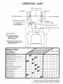
LUBRICATIONCHART
AXLE PIVOT
FRONT
!
®
SPINDLE
.-I-
WHEEL BEARINGS
(_
_WHEEL
MOWER CLUTCH PIVOT
Q
/:_
tJL)
BEARINGS
(_
E®
STEERtNG ROD
BOTH ENDS OF
FOOT PEDAL SHAFT
PIVOTQ
STEERING
ROD PIVOT
BOTH ENDS LIFT SHAFT (_}
(_) SAE MOTOR OIL
EXTREME PRESSURE
LUBRICATING GREASE
AMDEX NO. 1, SEARS
PART NO. 2557R
Q
REFER TO ENGINE OIL SPECS,
(UNDER INITIAL PREPARATION
IN OWNERS MANUAL)
SERVICE
RECORD
FILL IN DATES
AS YOU COMPLETE
REGULAR SERVICE
I
Check Engine0ii Level
Change Engine 0ii (see chart, page 6)
Lubricate
........................
Pivot Points
Check Brake Operation
Clean Air Screen
v"
......
_.........
V
i#"
_
II_
'
Clean Air Cleaner
Replace Air'.Cleaner
Paper Cartridge
Clean Engine Cooling Fins
Replace Spark Plug
Check Battery Level
Check Tire Pressure
i#
Replace Fuel Filter
Sears, Roebuck and Co, reserves the right to make any changes
in design or improvements
without
imposing
any obligation
22-to
install the same upon its items heretofore
manufactured..
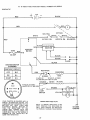
YT 14 TWIN YARD TRACTOR--MODEL
NUMBER
917.255813
_CHEMATIC
12V
__
BLACK
RED
O
O
RED
ATTACH
NEUTRAL
\
WHITE
SOLENOID"
RED
S
MO
..........
IGNITION
SWITCH
BLACK._MAGNETRON
L
.................
"]
[ ......
IGNITION
TTOL,C,
OB
30 AMP
O
G¢
\
L
/
.............
_.
BLACK
©
0
®
PLUGS
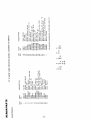
BLACK
IGNITION SWITCH
STD365402
POSITION
CIRCUIT
RECTIFIER
OFF
M-G
ON
B-L
START
B-S
RED
_
CHARGING_coIL
3 AMPS, DC
20 VOLTS, AC (MIN,)
AT 3600 RPM, BATTERY IN LINE
ORANGE
14 VOLTS, AC (MIN,)
_
WHITE
AC COIL
_
LIGHTS OFF AT 3600 RPM!_.'t
BROWN
LIGHT
SWITCH
YOUR TRACTOR 1S EQUIPPED WITH A
SPECIAL ALTERNATOR
SYSTEM. THE
LIGHTS ARE NOT CONNECTED TO THE
BATTERY,
BUT
HAVE
THEIR
OWN
ELECTRICAL
SOURCE, BECAUSE OF
THIS,
THE
BRIGHTNESS
OF THE
LIGHTS
WILL
CHANGE
WITH
THE
ENGINE SPEED. AT IDLE SPEED THE
LIGHTS WILL DIM. AS THE ENGINE IS
SPEEDED UP, THE LIGHTS WILL BE.
COME THEIR BRIGHTEST,
WIRING
INSULATED
CLIPS
NOTE: IF WIRING
INSULATED
CLIPS
WERE REMOVED FGR SERVICING OF
UNIT,
THEY SHOULD BE REPLACED
TO PROPERLY SECURE YOUR WIRING,
- 23 -
Z
CHAS:;IS
GROUNE
o
O_
L_
(.0
W
Z
J
L_
0
0
r_
0
i/
/
O
Z
lb-
W
I-
E
,-i
E
m
m
E
c.)
n_
lW
--I
24 -
>...
O
0
0
_
J
J
<
O
d
UJ
O0
<
I
Z
0
brr
00
o
ID
O3
UJ
O,I
a
r,,:
O
O
_
t:t, ''_
-
_
X..,_
0
G_
3
z_
O
L'3
_O _
'
O_
"-"
o._O
' c3 _..,: ,mz
o
OZ
_--
_
_
o
_
0
_
_
_
_:zz
x@x_
-o8@
_
N_xx
_o__
14.1
I:G
Cq r'l
_3
,-" _
o
:7
W
D
Z
.J
LU
>-
,,,d
O
l
O
I-
m 0== O@
<
I:l:
I,.-
o
13
<@@
,<
>Z
o
0
_oo
_--
v
I-
X+_
Q _C
'mO
Z
>-
o
I-
.':
'_
t::
OlD
T
tZ30"J .t'_ _
0-
_
.--1
O_ ''_'_
J
c:X
O
rr"
G,1
uJ
o
v
m
O3 _= Z
0
l-
m
_
_0_
_O
_m_NNmmm_oQNN_
n,
W
I..,
_d
_z
_1
E
lal
,<
o
Io
ILl
-J
W
- 25 -
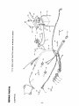
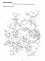
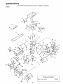
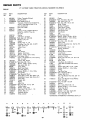
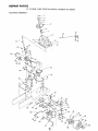
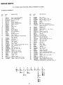
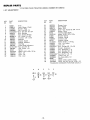
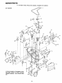
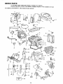
REPAIR
PARTS
YT 14 TWIN
CHASSIS AND
YARD
TRACTOR--MODEL
NUMBER
917.255813
ENCLOSU R ES
78
2
E
F
80
67
33
t4
18
69
2
57
G
72
49
38
61
P
75
"ra
36
28
- 26 -
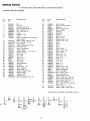
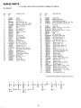
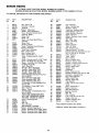
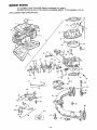
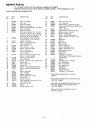
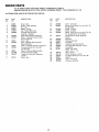
REPAIR
PARTS
YT
CHASSIS
AND
14 TWIN
YARD
TRACTOR--MODEL
NUMBER
917,255813
ENCLOSURES
KEY
NO,
PART
NO
DESCRIPTION
1
2
3
4
6
7
8
9
t0
11
108446X
I08176X
1055!3X
t05529X
73680500
73680600
105507X
t06202X
105801X
17490612
t2
t3
14
15
t6
18
t9
20
2t
22
23
24
25
26
27
28
29
30
31
32
33
34
35
36
37
19131312
STD523707
10551 tX
19131216
STD551137
t 055 t 2X
t05514X
19132012
105509X
t 0553 t X
!06020X
t05965X
6999R
5277J
106082X
108965X
102481 X
105523X
105505X
105522X
105525X
106092X
I05465X
t05464X
STD533707
Seat
Pan - Seat
Bracket * Pivot - Seat
Bolt- Shoulder 5/16- 18
Nut- Lock 5/16- 18
Nut- Lock 3/8_ 16
Fender
Reflector- Rear
Decal
Screw - Hex Washer Thread Rolling
3/8_ 16 x 3/4
Washer 13/32 x 13/16 x 12 Ga.,
*Bolt_ Hex 3/8- 16 x 3/4
Strap- Fender
Washer 13/32 x 3/4 x 16 Ga
* Lockwasher 3/8
Spring- Compression
Clamp _Spring
Washer 13/32 x 1 _ 1/4 x 12 Ga,
Bracket, Fender
Nut _ Push
Tank - Fuel
Cap - Fuel
Clamp- Hose
Line- Fuel
Pad o Spacer
Chassis Assembly
Drawbar
Panel _ Dash- L,H,
Cover ° Access
Panel- Dash - Roll,,
Bracket - Support _ Dash
Shield- Support
Footrest- L H.
Footrest - R.H.
"Bolt- Carriage 3/8 _ 16 x 3/4
KEY
NO,,
PART
NO.
DESCRIPTION
38
39
40
4t
42
43
44
45
46
47
48
49
50
54
55
56
57
58
59
60
6t
62
63
64
66
67
68
69
70
71
72
73
74
75
76
77
78
79
80
81
105466X
106297X
3645J
105809X
108885X
915tR
t05839X
I05838X
105751X
I05867X
109015X
109016X
!06013X
108067X
105528X
105806X
105568X
108744X
108743X
I05560X
108403 X
108410X
106091X
106090X
106003X
I06004X
106006X
t06005X
!08512X
I08513X
4900J
105813X
STD523710
8710J
105524 X
11050600
106813X
106814X
106974X
17490616
82
83
19131616
19131316
*STANDARD
A
B
C
D
®7
F
13@ 2o
_11
@6
E
@12
®7
G
J
1t
K
37 _74
®7
_77
®7
®7
27 -
L
Pad- Footrest
Bracket- Clutch - Mower
Bushing
Decal - 5 Speed - 38"
Guard- Muffler
Grommet
Receptacle
Retainer
Stud - !/4 Turn
Shield _ Heat
Bracket - Pivot - L_,H
Bracket- Pivot - R, H,
Hood
Pal Nut
Grill
Decal
Decal - Stripe
Decal. Hood- R,H
Decat _ Hood ° L H,
Decal o 14 H,,P.
Panel - Side- R H,
Panel - Side - L,H
Hinge- R ,H,
Hinge ,, L H,
Lens- R .H,
Lens- L_H,
Bezel - L,H,
Bezel- Roll
Bracket- Pivot- R,H,
Bracket o Pivot - L H
Decal o Clutch/Brake
Decal - Drive Belt
*Bolt- Hex 3/8- 16 x 1
Stem. Tank, Fuel
Strap Assembly - Grill
Washer, Lock, Ext, Tooth 3/8
Decal, Stripe, Side Panel, L H
Decal ° Stripe, Side Panel, R H
Decal., Opel - Caution
Bolt, Hex Washer Thread Rolling
3/8- t6 x 1
Washer 13/32 x 1 x 16 Gao
Washer t3/32 x 13/16 x 16 Ga
HARDWARE--PURCHASE
N
P
Q
_81
(_)
G 54
(_
_7
74
74
@ 82 @ 82
@ 83
®
7
LOCALLY
P RT8
YT
14 TWIN
YARD
TRACTOR--IVlODEL
NUMBER
917,255813
76
D
83
82
OPTIONAL
81
Spark Arr ester Screen
#
/
8O
84
- 28
EQUIPMENT
100091M
PARTS
YT
KEY
NO.
YARD
TRACTOR--MODEL
DESCRIPTION
PART
NO.
1
2
3
4
105703X
12000028
STD580025
108854X
5
7
8
105953X
106817X
t05949X
9
10
11
12
13
14
15
t6
t7
t8
19
20
21
22
23
24
108373X
!00229L
ST0522507
STD551!31
8545J
13280328
13300300
9767H
105732X
2751 R
106933X
t05699X
105701X
19151216
STD5612t0
17490612
25
26
27
28
29
30
31
32
33
34
35
36
37
38
39
40
41
42
43
44
45
46
47
105730X
ST05237!0
19131312
73680600
8883R
109037X
STD571810
19252016
I069t8X
STD580025
t06301X
10630(_
184777X
106191X
4470J
4859J
ST0523727
10573tX
10040700
74770720
106903X
4921H
I06294X
A
14 TWIN
B
Pulley, Transaxle (Driven)
Ring, Retainer
* Key, Woodruff No. 9
Transaxle, 5 Speed, Foote Model No.
4150-17 (see pages 36 and 37 for
parts breakdown)
Duct, Air intake
Foam
Engine, 14 H_P., Briggs & Stratton
Model No. 400707, Type No..
0111-02
Muffler
Tube Ass'y - Exhaust
*Bolt, H'ex, t/4 - 20 x 3/4
*Washer, Lock, 1/4
Gasket
Nipple, Pipe * 3- 1/2
Coupling, Pipe, Std 3/8- t8 NPT
Valve, Drain, Oit
V-Belt, Drive
Clip
Knob
Rod, Shifter
Washer - Shift Plate
Washer, 15/32 x 3/4 x 16 Ga.
*Pin, Cotter, 1/8 x 1
Screw- Hex Washer Hd. Thd,. Rolling
3/8- 16 x 3/4
Keeper, Belt, Engine
*Bolt, Hex, 3/8 -16 x 1
Washer, 13/32 x 13/16 x 12 Ga.
Nut, Lock, 3/8 - 16
Cover, Pedal
Shaft, Foot Pedal
*Pin, Roll, 3/t6 x t
Washer, 25/32 x t - 1/4 x 16 Ga.
Arm, Brake
* Key, Woodruff, No.. 9
Guide, Belt, Lower. Eng.. Pulley L.H.
Guide, Belt, Lower, Eng. Pulley R.H.
Guide, Belt
Keeper, Belt
Spacer
Idler, Flat
*Bolt, Hex 3/8- 16 x 2 - 3/4
Pulley, Engine
Washer, Lock, 7/16
Bolt, Hex, 7/16- 20 x 1 - 1/4
Keeper, Belt. L..H.
Retainer, Spring
Strap, Locator
C
D
E
F
G
NUMBER
917.255813
KEY
NO.
PART
NO.
48
51
52
53
54
55
56
57
58
59
6O
61
62
63
65
66
67
68
69
7O
7t
72
73
74
75
76
77
78
79
8O
106t90X
Clamp
STD523107 "Bolt, Hex 5/16 - 18 x 3/4
73680500
Nut, Lock, 5/16- 18
ST0523727
"Bolt, Hex. 3/8 - t6 x 2- 3/4
105842X
Strap, Torque
3723J
Bracket, Transaxte
106157X
Plate, Strap, Torque
76020412
Pin, Cotter, 1/8 x 3/4
I05844X
Rod, Brake, Park
105752X
Rod, Brake
7 t673
Cap
106888X
Spring, Rod, Brake
STD551037 *Washer, 13/32 x 13/16 x t6 Ga.
19252616
Washer 25/32 x I - 5/8 x 16 Ga.
t05724X
Bracket, Clutch
STD533707 "Bolt. Carro, 3/8 - 16 x 3/4
106298X
Pulley, Idler
105705X
Bellcrank Assembly (Inc, Key No. 9t)
106499X
Retainer, Belt
STD523715 "Bolt, Hex, 3/8- !6 x 1 - I/2
207J
Washer, Hardened
12000039
Ktip Ring
105709X
Spring, Return, Clutch
105710X
Link, Clutch
61159
Knob, Throttle Control
106678X
Control, Throttle
17720408
Screw, Hex Thd. Cut, t/4 - 20 x 1/2
59192
Cap, Valve
65'139
Stem, Valve
106268X
Tire, Rear, 18 x 9°50 x 8
7152J
Tube (Not furnished with tractor)
106108X
Rim
105702Y_
Spacer, Split, ,80' x 11 Ga, x 2.06
19252016
Washer, 25/32 x 1 - I/4 x 16 Ga.
12000001
E-Ring
104757X
Cap. Hub, Rear
STD580105
*Key - Square, 3/16 x 2
I06904X
Keeper, Belt, R.H.
17490624
Bolt, Hex Washer Thdo Roll. 3/8 : 16
xlI/2
]74905t2
Screw, Rex Washer Thread-RoHing
5/16. 18 x 3/4
STD523707
"Bolt, Hex 3/8 • 16 x 3/4
105706X
E_earing
73960500
Nut- Lock. Whiz 5/16- 18
19132012
Washer 13/32 x 1 -1/4 x 12 Gao
I06919X
Plate, Rod, Shift
I05700X
Spring - Torsion
11050600
Washer - Lock Ext. Tooth 3/8
ST0541237
*Nut- Hex Jam 3/8- 16
73510600
Nut- Keps 3/8- 16
• STANDARD HARDWAR E--PURCHASE LOCALLY
8t
82
83
84
85
86
87
88
89
9O
91
92
93
94
95
96
97
98
H
J
DESCRIPTION
K
L
M
N
88
27
2e
@=7
Q 93
@28
28
- 2g _
_)
27
_
28
,_96
98
REPAIR
PARTS
YT
STEERING
14 TWIN
YARD
TRACTOR--MODEL
NUMBER
917o255813
ASSEMBLY
ebb-----
3
37
38 57
2O
22
33
24
31
D
5O
63
42
54
43
48
66
69
56
57
50
53
67
68
REPAIR
PARTS
YT 14 TWIN YARD
STEERING
NUMBER
917,255813
ASSEMBLY
KEY
NO,
PART
NO.
1
2
3
4
5
6
7
8
9
10
11
12
13
14
15
16
17
18
I05810X
100710L
STD541350
100712K
100713N
100711 L
!06015X
t08407X
108809X
108402X
t06910X
t06909X
108705X
2882J
7 t208
10253! X
108685X
17490612
19
20
21
22
23
24
25
26
27
28
29
3O
31
32
33
34
35
36
37
38
TRACTOR-_MODEL
DESCR IPTION
Decal - Cap, Steering Wheel
Insert- Steering Wheel
* Nut- Hex 1/2 - 20
Washer
Wheel - Steering
Adapter - Steering Wheel
Sleeve - Steering
Dash
Decal - Dash
U-Clip
Washer
Screw - Special
Shaft - Steering
Pin - Drive 3/16 x 1
Bushing
Bracket - Steering
Gear- Pinion
Screw - Hex Washer Thread Rolling
3/8- 16 x 3/4
t08683X
Rod - Steering
12000029
Klip Ring
6266H
Bearing - Thrust
108684X
Gear- Sector
t06126X
Key _Woodruff
t05518X
Dash - Lower
74180512
Screw - Crown Truss Hdo 5/16 _ 18 x 3/4
73680500
Nut- Lock 5/16- t8
108263 X
Saddle
73680600
Nut- Lock 3/8 - 16
STD523120 *Bolt- Hex 5/16 - 18x 2
102949X
Spacer
106001X
Support Plate- Battery
STD523707
Bolt- Hex 3/8 _ 16 x 3/4
7603J
Tray - Battery
6999R
Clamp- Hose
100541K
Tube
6447J
Control - Choke
STD551037 *Washer 13/32 x 13/16 x 16 Ga.
t 1050600
Washer- Lock, Ext. Tooth 3/8
A
B
C
KEY
NQ
PART
NO.
40
41
42
43
44
45
46
47
105669X
105663X
74761060
105664X
105725X
105726X
73901000
17490508
48
49
50
51
52
53
54
55
56
57
58
59
60
61
63
64
65
66
67
68
69
_-70
71
73
74
75
76
78
79
80
D
E
D ESCR IPTION
Axle- Front
Support - Saddle - Rear
Bolt - Hex 5/8- 11 x 3 - 3/4
Support - Saddle _ Front
Spacer
Bearing
Nut - Lock - Flange 5/8- 11
Screw- Hex Washer Thread Rolling
5/16- 18 x 1/2
t05655X
Spindle- L.H
I05653X
Spindle- R.H.
19252016
Washer 25/32 x I - 1/4 x 16 Ga
I06440X
Rod - Tie
STD551131 *Washer - Lock 5/16
STD541131 *Nut-Hex5/16-24
3366R
Bearing
105727X
Link - Drag
STD551137 * Lockwasher 3/8
STD54t 137 * Nut- Hex 3/8- 24
1554J
Bushing - Steering
17431008
Screw - Hex No. 10 * 16 x 1/2
104757X
Cap- Hub _ Front
2751R
Clip _Fuel Line
100207K
Clip 3/8
59192
Cap _Valve
65139
Stem - Valve
278H
Fitting. Grease
9040H
Bearing
106732X
Rim - 6" Front
t06222X
Tire- Front
59904
Tube - Tire - Front
101930X
Washer, Hardened
108456X
Decal - Instruction, Operating
721 i 0622
Bolt - Carriage Hex 3/8 - 16 x 2- 3/4
106486X
Spacer
19131416
Washer 13/32 x 7/8 x 16 Ga.
74580
Spacer
STD541037 *Nut- Hex 3/8 _ 16
72110608
Bolto Carriage Hex 3/8 o 16 x 1
19252616
Washer 25/32 x 1 - 5/8 x 16 Ga
*STANDARD
HARDWARE--PURCHASE
LOCALLY
F
H
G
73
_)
79
@ 75
@
(_) 26
(_
75
56
- 31 -
56
78
REPAIR
PARTS
YT 14 TWIN
YARD
LIFT ADJUSTMENT
TRACTOR--MODEL
NUMBER
917,255813
14
d;°;o
4oZ
28
2O
39
4 .. '.,,.,,_D
44_
43-
i
_.39
U
44 __30
9
-32 -
REPAIR
PARTS
YT 14 TWIN
L1FT
KEY
NO L
1
2
3
4
5
6
7
8
9
10
11
12
13
14
15
16
t7
18
20
21
22
YARD
TRACTOR--MODEL
NUMBER
917_255813
ADJUSTMENT
PART
NOo
6465R
106861X
106498X
73680600
STD523707
206451X
108387X
76020412
106308X
106441X
108236X
I06444X
12000037
100734K
STD541237
100735K
2876H
19131016
105632X
106645X
106644X
DESCRIPTION
Knob
Lever - Mower- Clutch
Bracket - Pivot
Nut- Lock 3/8 - 16
* Bolt - Hex 3/8 .. t6 x 3/4
Bolt- Shoulder
Rod - Clutch - Primary
Pin - Cotter 1/8 x 3/4
Trunnion - Lift- Lower
Bellcrank
Bracket- Switch
Bracket- Beltcrank
Klip Ring
Knob, Depth Adjustment
*Nut-Jam
3/8- !6
Rod - Adjust- Lift
Spring
Washer 13/32 x 5/8 x 16 Ga,
Shaft- Lift
Lever- Lift
Rod- Lever
A
B
KEY
NO.
PART
NO.
23
24
25
26
27
28
29
30
3t
32
33
34
35
36
37
39
40
41
42
43
44
45
46
47
48
105723X
106019X
10601 tX
74570632
105630X
6519J
19151216
9135R
4939M
t06204X
4921H
19171616
105855X
105856X
STD533707
105864X
t05863X
105848X
I05862X
STD541050
73680800
76020308
58606
19131312
17021008
• STANDARD
C
26
- 33 -
E
D
37
DESCRIPTION
41
Plunger- Lever
Grip o Handle
Spacer * Split
Screw- Cap-SocketHd
3/8_ 16x2
Washer _ Nylon
Trunnion - Stop Depth
Washer t 5/32 x 3/4 x 16 Ga.
Retainer - Spring
Retainer - Spring
TrunnionLift
Retainer * Spring
Washer 17/32 x 1 x 16 Ga,
Link- Lift- Adjust
Link- Lift
* Bo_t • Carriage 3/8- t6 x 3/4
Bracket* Suspension
Arm - Suspension - LH.
Bolt _ Shoulder 3/8 - 16
Arm - Suspension- R.H..
*Nut-Hex
Fin. 1/2- 13
Locknut 1/2- 13
Pin, Cotter 3/32 x 1/2
Spring
Washer 13/32 x 13/16 x 12 Ga.
Screw - Hex Hd,. Tap_. No. 10-24 x I/2
HARDWARE--PURCHASE
LOCALLY
REPA|R
PARTS
YT 14 TWIN
YARD
TRACTOR--MODEL
NUMBER
917.255813
38" MOWER
L
45
16
t4
I5
CC
22
A
55
5
4
B:
]
jB
13/9
46
60
36
±
NIl
H
-11
H
J
H
H
IF REAR BAGGER ATTACHMENT
IS BEe
ING USED, REFER TO REAR BAGGER
OWNERS MANUAL
FOR BLADE PART
NO.
41 42
41 42
- 34
13), ," 8
PARTS
REPAIR
YT
14 TWIN
YARD
TRACTOR--MODEL
NUMBER
917.2558t3
38" MOWER
KEY
NO
PART
NO
DESCRIPTION
t
2
3
4
5
6
7
8
9
10
1t
12
13
14
t5
16
17
18
19
20
2t
22
23
24
25
26
27
28
29
30
32
33
106085X
105689X
84t7J
73680600
19111216
72140505
105896X
5846R
106734X
106735X
106736X
1058t4X
105304X
t05662X
I05744X
3t46R
105872X
105743X
STD523707
73680500
t05659X
t05660X
STD533107
37t3J
106295X
I05850X
106975X
106461X
STD523720
108832X
102403X
106902X
V-Belt
Housing
Runner, R H
Nut, Lock, 3/8- 16
Washer, 1!/32 x 3/4 x 16Ga,
Bolt, Carr,, 5/16- 18 x 5/8
Bracket, Deflector
Nut
Spring, Deflector
Rod - Hinge
Deflector - Shield
Decat
Cap
Link, Parallel
Pin, Front Hinge
Spring- Retainer
Stop, Link
Pin, Rear Hinge
*Bolt 3/8- 16 x 3/4
Nut. Lock 5/16 - t8
Bracket, Lift, R.H
Bracket, Lift, L H
*Bolt, Carr 5/16- 18 x 3/4
Instruction - Caution Decal
Support, Arm
Stop, Deck, Front
Decal - Safety Standard
Guide, Belt
*Bolt 3/8 - t6 x 2
Arm, Idler
Pulley, Idler
Spacer - Retainer
KEY
NO
PART
NO
34
35
36
37
38
102669X
105891X
100668L
17490612
17490620
39
40
4I
42
43
44
45
46
47
48
49
50
52
53
54
55
56
57
58
59
60
61
62
63
64
65
66
67
68
69
70
7t
72
73
74
t06634X
19132012
STD551137
STD6327t5
I08250X
I08235X
492t H
STD560907
108068X
76020616
I08247X
STD533707
I08243X
t08241X
105857X
108673X
106578X
I06463X
108249X
106456X
100672K
I00673L
106514X
19111016
74760684
7631J
19131614
72140610
78850
STD55t037
19141610
72110606
19132012
106679X
76020308
DESCRIPTION
Keeper, Belt
Mandrel Assembly
Plate, Support, Mandrel
Screw, Hex Washer Hdo 3/8 - 16 x 3/4
Screw, Hex Washer Hd 3/8 - 16
x 1 -1/4
8lade, 38"
Washer 13/32 x 1 - 1/4 x 12Ga,
*Washer, Lock, 3/8
*Bolt, Hex, 3/8- 24 x 1 - 1/2 Gr 5
Spring. Ext
Rod
Spring, Retainer
* Pin, Cotter, 3/32 x 3/4
Shaft Assembly, Rock
Pin, Cotter, 3/16 x 1
Rod. Brake. Primary
*Bolt, Cart, 3/8 - 16 x 3/4
Bracket, Pivot, R H
Bracket, Pivot, L H
Bracket, Susp, Rear, R H
Bracket, Susp=, Rear, L H
Brake
Rod, Brake, Secondary L H
Rod, Brake, Secondary, RH
Bracket, Brake, Pivot
Spacer, Brake
Bracke_, Support
Washer, Wear 3/16
Washer, 11/32 x 5/8 x 16 Ga
Bolt, 3/8 - 16 x 5 - 1/4
Runner, LH
Washer 13/32 x 1 x 14 Ga
Bolt, Carr, 3/8- 16 x 1 - 1/4
Decal - Warning
*Washer 13/32 x 13/t6 x 16 Ga,
Washer 7/16 x 1 x 10 Ga,
Bolt, Carriage 3/8 - 16 x 3/4
Washer 13/32 x 1 - t/4 x 12 Ga
Decal Warning
Pin, Cotter 3/32 x 1/2
'STANDARD
A
B
C
D
E
G
J
H
37
@
5
@2o
@ 20
_"_ 4
(_
@
70
38
04
C) 20
4
- 35 -
K
HARDWARE--PURCHASE
L
M
N
67
LOCALLY
REPAIR
TRANSAXLE
PARTS
YT 14 TWIN
TRANSAXLE
YARD
TRACTOR--MODEL
FOOTE--MODEL
NUMBER
NUMBER
4150-17
917o255813
19
16
14
38*
46
58
59
6O
65
66
57
58
- 36 -
_63
REPAIR
PARTS
YT 14 TWIN
TRANSAXLE
TRANSAXLE
YARD
TRACTOR--MODEL
FOOTE--MODEL
NUMBER
NUMBER
4150-17
KEY
NO.
PART
NO,
DESCRIPTION
KEY
NO
PAR'[
NO
I
2
3
4
5
6
7
8
8
8
8
8
8
8
8
8
9
10
tI
12
I06845X
22765
2274J
68003
105904X
t05905X
2267J
2233J
2232J
223t_J
2230J
2229J
2228J
2227J
2226J
105906X
6725J
2228J
2257J
106094X
13
14
15
16
17
!8
19
20
21
22
23
24
25
26
27
28
29
30
3t
32
33
34
35
36
t06095X
t05909X
105910X
105911X
108976X
1059t3X
105914X
2242J
1059t5X
2244.J
I05916X
105917X
105918X
t08977X
108978X
t08979X
108980X
t08998X
108455X
t05925X
108981X
I05927X
34t3J
105928X
Housing, Upper
Screw, Tapping, t/4 - 20 x 1.31 Lg.
Screw, Tapping, 1/4 - 20 x ,875 Lg
Ball, Detent
Spring, Detent
Screw, Set
Ring, Retaining
Washer, Plain, .632 x 1BOx ..020
Washer, Plain, .632 x 100 x .026
Washer, Plain, .632 x 1,00 x .031
Washer, Plain, .632 x 1.00 x .036
Washer, Plain, ..632 x 1.00 x o041
Washer, Plain, ,632 x 1.00 x .046
Washer, Plain, 632 x 1.00 x ,050
Washer, Plain, 632 x 1o00 x 060
Washer, Plain, 632 x 100 x 082
O-Ring
Washer, Plain, ,632 x t00 x .046
Key, Woodruff, No. 9
Assembly, Kit, Input Shaft (tnc's. Key
No's. 7, 8, 9, 1I, 13, t4, 68 and 2 each
Key No's. 10 & 37)
Pinion Bevel 14T
Ring, Retaining
Chain, 24 Pitches
Bearing, Flange
Gear, Spur, 14T
Collar, Clutch
Key, Clutch
Key, Woodruff, No. 3
Shaft, Intermediate
Key, Woodruff, No 61
Ring, Retaining
Sprocket, 18"1"
Spacer
Gear, Spur, 37T
Spacer
Gear, Spur, 30T
Gear, Spur, 25T
Gear, Spur, 22T
Gear, Spur, 19T
Washer, Plain, 640 x t.37 x .061
Assembly, Gear, Comb., 12T & 35T
Shaft, Idler
Washer, Plain, 631 x 1.00 x .010
Sprocket, 9T
37
38
38
38
38
38
38
38
38
38
38
38
38
38
39
40
41
42
43
44
45
46
47
48
49
50
51
52
53
54
55
56
57
58
59
60
61
62
63
64
65
66
67
68
69
70
71
72
t06605X
108983X
t05930X
105931X
I05932X
3417J
106097X
2264J
106098X
22653
t06586X
106587X
I06588X
2263J
105933X
105934X
106589X
I06130X
t05937X
105938X
2226J
2272J
2264J
106590X
t06591X
105941X
2268J
22705
106596X
106593X
I08986X
108987X
105945X
108988X
64260
108989X
108990X
108991X
108992X
!08993X
108994X
t08995X
108996X
106592X
106782X
..............
I08727X
I08997X
- 37 -
917.255813
DESCRIPTION
Gear, BevP', 42T
Washer, Pi_in, .758 x 1,12 x ,010
Washer, Pt_;n, .758 x 1.12 x o015
Washer, PIai% .,758 x 1.12 x ,020
Washer, Plain, ,,758 x 1.12 x ,025
Washer, Plain, .758 x 1.25 x .020
Washer, Plain, °758 x 1o25 x .025
Washer, Plain, .758 x 1.25 x,031
Washer, Plain, .758 x 1.25 x 035
Washer, Plain, .758 x t ,25 x °040
Washer, Plain, .758 x 1.25 x °045
Washer, Plain, .758 x 1,25 x .,050
Washer, Plain, .758 x 1_25 x B55
Washer, Plain, °758 x 125 x -062
Gear, Spur, 12T
Gear, Spur, 20T
Gear, Spur, 25T
Gear, Spur, 28T
Gear, Spur, 31T
Shaft, Drive
Washer, Plain, .640 x 1.00 x .060
Seal, Felt
Washer, Plain, .758 x 125 x 031
Axle, L.H
Gear, Miter, 15T
Ring, Retaining
Gear, Spur, 32T
Shaft, Cross
Screw, Tapping, 5/16- 18 x 1o44 Lg.
Axle, R.H.
Assembly, Shifter
Cap, Support
Housing, Lower
Puck, Friction
Disc t Brake
Spacer
Assembly, ,Jaw, Brake
Pin, Dowel
Lever, Actuating
Screw, Tapping, 5/16 - 18 x 1.5 Lg_
Spacer, .323 x ..563 x 1.00 Lgo
Screw, Tapping, 5/16- 18 x 250 Lg°
Washer, Plain .321 x 1.00 x .055
Gear, Miter, 15T
Bearing, Needle
+Input Shaft
V-Ring
Nut, Lock, 5/16- 24
*USE IN VARIOUS COMBINATIONS
TAIN PROPER CLEARANCES
TO MAIN.
+NOT SOLD SEPARATELY--ORDER
KEY NOo 12
REPAIR pARTS
YT 14 TWIN YARD TR ACTOR+'MODEL
ENGINE BRIGGS & STRATTON--MODEL
CYLINDER,
CRANKSHAFT
2
AND ENGINE
NUMBER 917o255813
NUMBER 400707, TYPE NUMBER
0111-02
BASE GROUP
3
74
" !
70
_
75
68
I
|6
66"
18
71
37
36
20
58
61
22
59
55
25
54
24.
5:t-.--_
•
I
|
O
.38 -
REPAIR
PARTS
YT 14 TWIN YARD
ENGINE
CYLINDER,
BRIGGS
CRANKSHAFT
KEY
NOr
PART
NO,
1
2
3
4
5
6
7
8
9
10
90576
280180
231174
27803
92791
222892
93722
93394
222912
93777
11
12
I3
14
15
16
17
18
19
93158
393287
93882
270981
222860
261463
210940
212462
93111
20
21
22
23
24
25
25
25
25
26
93113
93686
92290
393415
260924
394959
394960
394961
394962
394955
26
26
25
27
394956
394957
394958
299691
27
28
29
30
391286
394348
222773
39327O
3t
32
33
34
35
36
37
37
37
92909
220863
291675
91084
393552
270983
271142
271188
271189
TRACTOR-MODEL
& STRATTON--MODEL
AND
ENGINE
NUMBER
NUMBER
917.255813
400707,
TYPE
NUMBER
0111_02
BASE GROUP
DESCRIPTION
Nut- Hex 8 - 32
Grommet- Insulator
Terminal
* Gasket- Valve Cover
Washer * Lock, Shakeproof
Cover - Breather Cylinder No. 24
Terminal - Spade
Screw - Sem
Baffle _Air
Screw - Hex Head (Back Plate to
Cylinder)
Screw - Sere
Housing- Blower
Screw- Crankcase Cover Mtg. Sere
* Gasket _Crankcase
Cover Plate - Crankcase
+Seat - Intake Valve
+Seat - Exhaust Valve
Head - Cylinder No, 2
Screw - Cylinder Head (1- 15/16"
Long)
Screw - Cylinder Head (2 - 5/16" Long)
Screw* Hex Head (10 ° 32 x 5/8)
Washer- Lock (No. t0 x 1/16 x 3/64)
Oil Slinger Assembly
Lock - Piston Pin
Ring Set - Piston (Standard)
Ring Set- Piston (o01'0" OoSo)
Ring Set- Piston (°020" O.S.)
Ring Set- Piston (.030" O.S.)
Piston Assembly (Standard) (lnco Key
No's. 24 & 25)
Piston Assembly (.010" O.So)
Piston Assembly (.0_0" O.S_)
Piston Assembly (,030" O,S.)
Pin Assembly. Piston (Standard) (Inc.
Key No. 24)
Pin Assembly _ Piston (.005" OoS,)
Gear- Governor
Washer - Th rust
Rod Assembly - Connecting (Inc. Key
No's. 31 & 32)
NOTE; FOR CONNECTING ROD
WtTH .020" UNDERSIZE CRANKPIN BORE. ORDER NOr 393714
Screw - connecting Rod
Washer
Seal - Oil
Plug- Oil Drain
Base Assembty _Crankcase
* Gasket - Cylinder Head No. 2 '
*Gasket- Crankcase Cover (1/64" thick)
* Gasket - Crankcase Cover (,005" thick)
*Gasket
Crankcase Cover (_009" thick)
KEY
NO.
PART
NO,
38
39
40
41
42
43
44
45
46
47
48
49
50
51
52
53
54
222698
93585
93851
271316
261560
261559
394349
220863
394501
271157
93469
212337
222875
280224
271170
394020
394394
55
56
57
59
60
61
62
63
64
65
66
67
68
69
70
71
72
73
390419
261528
231321
26828
292260
93630
221596
65906
261368
393382
231218
394941
230318
394539
66538
89838
280225
394358
74
75
76
77
78
79
80
81
82
83
212461
270984
392934
261623
391086
298693
299146
93053
393370
223167
* INCLUDED
DESCRIPTION
Key- Flywheel
Screw- Hex Hd. Sem
Retainer _E-Ring
Foam Seal - Governor Shaft
Upper Bushing - Governor
Lower Bushing - Governor
Crank - Governor
Washer- Governor Crank (Inside)
Gasket Set
Seat - Filler Tube
Screw - Hex Head
Gear _Cam
Clamp - Oil Filler
Tube _ Oil Filler
Seal - Oil Filler Cap
Cap and Dipstick . Oil Filler
Dipstick and Tube Assembly (Inc. Key
No_s, 47, 48, 50, 51, 52 & 53)
Valve - Exhaust
Valve _ intake
Gear - Timing
Spring - Exhaust Valve
Rotocoi! - Exhaust Valve
Retainer - Exhaust Valve Rotocoil
Retainer- Intake Valve
Spring o Intake Valve
Tappet * Valve
Crankshaft
+Guide - Exhaust Valve
Cylinder Assembly (Inc. K_y No. 68)
Connector -Jmpulse Pump
Plug - Spark (Resistor)
Elbow- Spark Plug
Wrench - Spark Plug
Tube Breather
Filter- Fuel (In Fuel Line to
Tank)
Head - Cylinder No. I
• Gasket - Cylinder
Back Plate Assembly
+Bearing. Cylinder
Seal - Oi!
Wire - Ground
Line - Fuel (lnc, Key No, 81)
Clamp, Fuel Line
Breather Assembly No_ 1
Clamp- Fuel Pipe
IN GASKET SET 394501
+SPECIAL TOOLS REQUIRED
- 39 -
TO INSTALL
REPAIR
PARTS
YT 14 TWIN YARD
TRACTOR--MODEL
ENGINE
BRIGGS
& STRATTON--MODEL
AIR
CLEANER
AND
NUMBER
917.255813
NUMBER
400707,
TYPE
NUMBER
0111-02
CARBURETOR
61
13
15
59
48 \
57
56
50
53
4t
39
4O
30
22
25
- 40 -
REPA|R
PARTS
YT 14 TWIN YARD
TRACTOR--MODEL
ENGINE
BRIGGS
& STRATTON--MODEL
AIR
CLEANER
KEY
NQ
PART
NO,
1
2
3
4
5
6
7
8
212292
93715
223002
271271
394546
93893
222861
398107
398108
10
11
271411
93499
12
t4
15
16
t7
222010
392673
271609
298514
93496
t8
397270
t9
20
21
22
23
24
25
26
231209
22337O
271412
93897
93971
280320
270884
93208
27
28
29
30
31
32
33
93970
261587
280319
394374
93158
261720
394470
34
35
36
92278
222289
261563
AND
NUMBER
917,255813
NUMBER
400707,
TYPE
NUMBER
0111-02
CARBURETOR
DESCRIPTION
Knob - Air Cleaner
Nut- Hex
Cover - Air Cleaner
Element - Air Cleaner
Mounting Strap Assembly - Air Cleaner
Screw- Hex Head
Body - Air Cteaner
Carburetor Assembly (Inc. Key No's.
9, 10, 11, 12, t4, 15, 16, 17, 19, 20,
42,43,44,45,46,47,48,49,50,51,
52, 53, 54, 55, 56, 57, 62 & 63)
Body Assembly
Upper Carburetor
(Inc_ K_y No'so I1, 12, 14& 15)
Gasket- Air Cleaner
Screw -Throttle and Choke
Valve Mounting Sere
Valve - Choke
Shaft and Lever _Choke
+Gasket- Carburetor Body
Float _Carburetor
Screw- Hex Head Sem
(10 - 32 x 5/8)
Body - Lower Carburetor (Inc Key
No's. 11, 19, 20,45 & 46)
Bushing- Throttle Shaft
Valve - Throttle
+_
Gasket- Carburetor and Intake Elbow
Screw. Sere
Screw- Hex Head
Crank- Bell
* Gasket - Intake Manifold Mounting
Screw- Intake Manifold Mounting
Sem
Screw- Hex Head
Link _Throttle
Spacer - Carburetor
Manifold Assembly - Intake
Screw- Sem
Spring _ Governor
Lever Assembly - Governor (Inc, Key
No_s,,34, 35 & 37)
Nut- Hex (t0- 24)
Washer
Spring- Governor ldle
KEY
NQ
PART
NO.
37
38
39
40
93853
261586
394538
390674
4t
44
45
46
47
48
93053
292681
392672
271013
26157
91920
49
50
51
52
53
54
55
56
57
58
59
270988
261358
221377
261395
222615
93829
271025
270989
280197
394501
394019
60
61
62
63
65
66
67
-----
271180
222859
230896
299096
231339
397882
280474
393397
394502
DESCRIPTION
Bolt, Governor Lever
Link- Governor
Ptate Assembly - Governor Control
Impulse Line and Clamp Assembly (lnc,,
Key No. 41 )
Clamp - Fuel Line
+Valve Assembly - Carburetor Idle
Shaft and Lever - Throttle
+Washer- Choke Shaft
Spring - Throttle Adjustment
Screw - Machine Fill, Hd. (8 - 32 x
5/8)
*INCLUDED
394501
x Diaphragm
xSpring
x Cap - Spring
xSpdng - Pump
Cover - Diaphragm
Screw - Diaphragm Cover
xGasket- Carburetor Pump
x Diaphragm - Damping
Body _ Pump
Gasket Set
Cartridge o Air Cleaner
NOTE: USE 271197 GASKET BELOW
CARTRIDGE
Washer
Cartridge Plate - Air Cleaner
+Pin - Float Hinge
+VaNe - Fuel Inlet
° Jet - Needle Valve
Plug & Seal
O-Ring Seal
Repair Kit. Pump
Overhaul Kit- Carburetor
IN GASKET
SET . PART NO
+INCLUDED
IN CARBURETOR
PART NO., 394502
OVERHAUL
KIT-
xlNCLUDED
IN CARBURETOR OVERHAUL
KIT PART NO, 394502 AND PUMP REPAIR KITPART NO, 393397
°HIGH ALTITUDE
- JET-NEEDLE
PART NOo 231333
VALVE
REPAIR
PART8
YT 14 TWIN YARD TRACTOR_MODEL
NUMBER 917,255813
ENGINE BRIGGS & STRATTON-_MODEL NUMBER 400707, TYPE NUMBER 0111-02
ALTERNATOR
AND STARTER MOTOR GROUP
2
5
1
10
40
39
15
16
34
32 31
- 42
17
REPAIR
PART8
YT 14 TWIN "YARD TRACTOR--MODEL
ENGINE
BRIGGS
& STRATTON--MODEL
ALTERNATOR
KEY
NQ
AND
STARTER
MOTOR
NUMBER
NUMBER
917,255813
400707,
TYPE
NUMBER
0111-02
GROUP
PART
NO.
DESCRIPTION
KEY
NO,
PART
NQ
DESCRIPTION
1
2
3
4
5
6
93805
222673
231247
222511
222674
392956
18
19
222849
396865
20
2!
24
222846
222847
3948O8
8
9
393456
393474
25
395537
10
11
93621
391362
12
13
19203
394891
26
27
28
29
30
31
32
395538
393825
94003
392747
394860
90366
91162
t4
15
t6
93381
221798
394970
17
93163
Screw - Sem
Screen - Flush Rotating
Nut _ Hex
Washer - Spring
Cup - Screen Mounting
Flywheel and Ring Gear
Assembly - Magneto
Diode and Connector Assembly
Stator- Alternator (Dual Circuit)
(Inc. Key No, 8)
Screw - Sere
Gear- Flywheel Ring (Includes
Mounting Parts}
Puller- Flywheel (Optional Accessary)
Armature Group (Inc. Key No's,
15, 16 & 40)
Screw - Armature Mounting Sem
Terminal- Ignition Cable
Trigger Coil Assembly Magnatron
Ignition
Screw- Sere
33
34
35
36
39
40
280104
391135
393254
93754
222848
394988
Cover - Air Guide
Starter Drive Group (tnc Key No's. 33,
34, 35 & 36)
Shield - Cylinder
Shield - Cylinder
Motor - Starting (Inc. Key No's. 25, 26,
27, 28, 29, 30, 31, 32, 33 & 34)
Commutator End Cap Assembly
Starter
Brush Set
Housing Assembly
Thru Bolt
Armature Assembly (Motor}
Drive End Cap Assembly - Starter
Lockwasher
Screw- Hex Head
(5/16- 18 x 1 - I/2
Gear - Starter
Clutch Assembly - Starter
Kit Pinion Spring (lnc, Key No 36)
Roll Pin
Cover - Air Guide
Armature Assembly
- 43 -
SERVICE
NOTES
_44-
SERVICE
NOTES
45_
SERVICE
NOTES
46 -
SUGGESTED
GUIDE
FOR SIGHTING
SLOPES
FOR SAFE
ONLY
NOT
SIGHTING
RIDE
SIGHT
AND HOLD THIS
SKY LINE OR TREE
15 °
LEVEL
WITH
MAX.
Operate
your Tractor
up and down the face of slopes (not
greater than 15°); never across the face. Make turns gradually to prevent
tipping
or loss of control.
Exercise extreme
caution when changing direction
on slopes.
UP AND
ACROSS
GUIDE
OPERATION
HILL
DOWN
HILL
OWNERS
MANUAL
YT 14 TWIN
5 SPEED
YARD TRACTOR
MODEL NO.
917.255813
The Model Number' wilt be found on the Model Plate attached
to the Fender, Always mention the Model Number when requesting service or parts for your Yard Tractor.
All parts listed herein may be ordered from any Sears Service
Center/Departments
and most Sears Retail Stores,
WHEN ORDERING
REPAIR
FOLLOWING
INFORMATION:
HOW TO ORDER
REPAIR PARTS
0
•
®
®
THE
THE
THE
THE
PARTS,
ALWAYS
GIVE
THE
PART NUMBER
PART DESCRIPTION
MODEL NUMBER
NAME OF MERCHANDISE
If the parts you need are not stocked locally, your order will
be electronically
transmitted to a Sears Repair Parts Distribution Center' for "expedited handling'L
Sears, Roebuck and Co., Chicago, IL 60684 U,S.A.