1
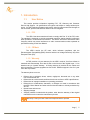
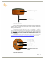
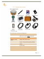
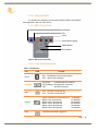
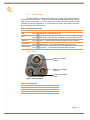
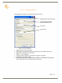
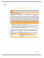
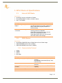
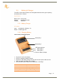
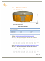
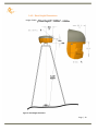
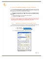
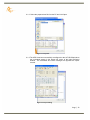
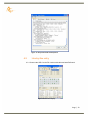
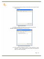
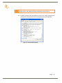
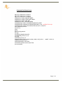
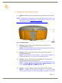
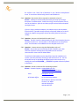
APS-3 User Manual Revision 2.00 Page | 1 APS-3 User Manual © 2011 ALTUS Positioning Systems Inc. All rights reserved. ALTUS, the ALTUS logo, and APS-3 are trademarks of ALTUS Positioning Systems Inc. registered in the U.S. and other countries. No part of this document may be copied, used or reproduced without the prior written permission of ALTUS Positioning Systems. No part of this manual may be reproduced or transmitted in any form or by any means, electronic or mechanical, including photocopying and recording, for any purpose without the express written permission of ALTUS Positioning Systems Inc. Mention of third-party products in this document is for informational purposes only and does not constitute an endorsement or a recommendation. ALTUS Positioning Systems assumes no responsibility with regard to the performance or use of the APS-3 due to GPS characteristics, USA Department of Defense operations control, atmospheric effects, multipath and RF interference. All understandings, agreements, or warranties take place directly between the seller and the prospective users. Every effort has been made to ensure that the information in this manual is accurate. ALTUS is not responsible for printing or clerical errors. All specifications are typical and subject to change without prior notice. Page | 2 Table of Contents 1. Introduction ..................................................................................................... 5 1.1. User Notice ....................................................................................................................... 5 1.1.1. FCC ....................................................................................................................5 1.1.2. CE Mark .............................................................................................................5 1.1.3. Warranty .............................................................................................................5 1.1.4. Customer Service and Support ...........................................................................6 1.2. Foreword .......................................................................................................................... 6 1.2.1. Related Software ................................................................................................ 6 1.2.2. Revision History .................................................................................................6 2. APS-3 Overview ............................................................................................... 7 2.1. APS-3 Key Features .........................................................................................................7 2.1.1. Navigation Accuracy .......................................................................................... 7 2.1.2. APS-3 Ease of Use ............................................................................................. 7 2.1.3. Shipping Case Contents ...................................................................................... 9 2.1.4. Using the APS-3 ............................................................................................... 10 2.1.5. APS-3 Front Panel ............................................................................................ 10 2.1.6. Front Panel Description .................................................................................... 10 2.1.7. Power Button .................................................................................................... 11 2.1.8. Ports.................................................................................................................. 11 2.1.9. Power Input ...................................................................................................... 12 2.1.10. SIM Card .......................................................................................................... 12 2.1.10.1. Purchasing a SIM Card w/ plan ......................................................... 12 2.1.10.2. Installing SIM Card ........................................................................... 13 2.1.11. SD Card ............................................................................................................ 13 2.1.11.1. Removing SD Card ........................................................................... 13 2.1.11.2. Installing SD Card ............................................................................. 13 2.1.11.3. Formatting SD Card .......................................................................... 14 2.1.11.4. Known Compatible SD Cards ........................................................... 15 3. APS-3 Device & Specifications ..................................................................... 16 3.1. Internal UHF Radio ....................................................................................................... 16 3.2. GSM Modem .................................................................................................................. 16 3.2.1. Communication Protocol .................................................................................. 16 3.3. Battery & Charger ......................................................................................................... 17 3.3.1. Battery Charger ................................................................................................ 17 3.3.2. Charging Battery .............................................................................................. 17 3.3.3. APS-3 Battery Installation and Replacement ................................................... 18 3.4. GNSS Antenna Offsets .................................................................................................. 19 3.4.1. NGS Calibration ............................................................................................... 19 Page | 3 3.4.2. Slant Height Dimensions .................................................................................. 20 4. Factory AsteRx2/AsteRx2e receiver Settings.............................................. 21 4.1. Uploading a script/text file using RxControl ............................................................... 21 4.2. Line-by-line entry .......................................................................................................... 23 5. Frequently Asked Questions......................................................................... 27 6. List of Typical GNSS Related Acronyms .................................................... 31 7. Table of Figures ............................................................................................. 32 Page | 4 1. Introduction 1.1. User Notice This section provides information regarding FCC, CE, Warranty and Customer Service with Support. All specifications are typical and subject to change without prior notice. ALTUS Positioning Systems reserves the right for improvements and changes to this document, products and services without notice or obligation. 1.1.1. FCC The APS-3 has been tested and found to comply with Part 15 of the FCC rules. The standard is designed to provide reasonable protection against harmful interference when operated in a commercial environment. This device will receive and transmit radio frequency which may cause interference to radio communications unless operated as specified according to this User Manual. 1.1.2. CE Mark The APS-3 carries the CE mark, which indicates compliance with the Electromagnetic Compatibility (EMC) directive and the Low Voltage Directive (LVD) of the European Union (EU). 1.1.3. Warranty ALTUS provides a 2-year warranty for the APS-3 receiver, free from defects in materials and workmanship, from date of sale on the invoice of the original buyer. Li-ion batteries carry a 6-month warranty. A 90-day warranty is provided for the cables and other accessories. Firmware upgrades are free for life. Software support is free for 1-year from date of purchase. The warranty does not cover: Defects due to accidents, abuse, misuse, negligence, abnormal use or any other non-recommended use. Defects due to environmental conditions that do not conform to APS-3 specifications Defects due to improper installation or operating procedures Defects due to modifications, alterations, or changes not made in accordance with the APS-3 User Manual and other technical documentation or directly authorized by ALTUS Normal wear and tear use Shipping damage 3rd-party software included with the product, other than the warranty of the original manufacturer to the extent the manufacturer permits Warranty is void if the APS-3 has been tampered with or opened. Page | 5 1.1.4. Customer Service and Support Contact your ALTUS dealer for first-line support. Further problems or questions, please contact ALTUS Positioning Systems support. [email protected] http://www.altus-ps.com/support or write to ALTUS Positioning Systems 20725 Western Avenue, Suite 100 Torrance, CA 90501 (310) 541-8139 office (310) 541-8257 fax 1.2. Foreword Congratulations on purchasing the APS-3. The APS-3 is a high precision GNSS satellite receiver with integrated state-of-the-art wireless communications specifically designed for the Surveying market. This APS-3 User Manual contains important reference information to assist you with using your new receiver. 1.2.1.Related Software ArWest AWLaunch Carlson SurvCE MicroSurvey FIELDGenius Septentrio RxControl 1.2.2. Revision History Rev 1.00 (November 2008) Rev 1.01 (February 2009) Rev 1.02 (June 2009) Rev 2.00 (March 2011) Initial Release Subsequent Release Subsequent Release Subsequent Release Page | 6 2. APS-3 Overview 2.1. APS-3 Key Features The APS-3 is an all-in-one, cable free solution for your Surveying needs. It’s a simple and easy to use GNSS surveying product, which provides the following features: 136 Channel AsteRx2e GNSS receiver, with L1/L2/L2C GPS, GLONASS and SBAS. Bluetooth® Internal GSM or CDMA Modem to communicate with RTK Networks Internal digital UHF Radio to receive/transmit RTK corrections Two (2) Lithium-Ion Batteries for up to 10 hours of use Easy-access removable SIM card for cellular service (SIM card not Included) Easy-access removable 2GB SD Card for internal data logging. 2.1.1. Navigation Accuracy Navigation Performance Standalone (Autonomous) SBAS (WAAS, EGNOS, MSAS) DGPS (RTCM1,3 / 9,3) RTK Table 1: Navigation Accuracy Horizontal (m) 1.3 0.6 0.5 0.01 + 1 ppm Vertical (m) 1.9 0.8 0.9 0.02 + 1 ppm 2.1.2. APS-3 Ease of Use GNSS Antenna LED Status Indicators Power Button Release Button for Battery Compartment Battery A Compartment Battery B Compartment Figure 1: APS-3, Front View Page | 7 SIM & SD Card Compartment UHF Radio Antenna Figure 2: APS-3, Rear View The rear view of the APS-3 shows the door to access the SD card and SIM card. GNSS raw data can be saved to the SD Card, and the SIM card allows cellular service with the internal GSM modem. The ports and the product label can be seen on the underside of the APS-3. There are 3 ports: two serial ports and one external power input port. Also located on the base of the APS-3 is a TNC connector for a UHF antenna, which is utilized by the internal radio. ALWAYS connect a UHF antenna before powering ON the APS-3. The threaded connector in the middle is a standard 5/8” connector for mounting onto survey poles or accessories. NGS relative calibration value for the APS-3 L1 vertical offset is 113.5 mm. See http://www.ngs.noaa.gov/cgi-bin/query_cal_antennas.prl?Model=APS for information. Data (8-pin LEMO) Power (4-pin LEMO) Control (5-pin LEMO) Model & Serial # 5/8” Thread Nut CE / FCC / Bluetooth® Label TNC Connector for UHF Radio Antenna Figure 3: APS-3, Bottom View Page | 8 2.1.3. Shipping Case Contents Table 2: Shipping Contents APS-3 UHF Radio Antenna 2GB SD Card SIM Card Holder** Allegro MX* (2) Lithium-ion Batteries Battery Charger AC Adapter Archer* Power Cable; unterminated Controller Cable Data Cable* *- Optional Items ** - SIM Card not included A full APS-3 system consists of the following items: Items What to use it for UHF Radio Antenna A UHF Radio Antenna should be connected to the APS-3’s TNC connector before powering ON Lithium-ion Battery Battery Charger Handheld Controller Device Controller Cable Data Cable Power Cable Preinstalled Items SD Card SIM Card Holder Provides internal power to the APS-3 Charge the lithium-ion batteries Configure and control the APS-3 RS232/Serial connectivity to handheld controller or computer. [Required when upgrading firmware] Communication to devices such as external radios or modems Provide 9-15 VDC external power with use of battery or power supply What to use it for 2GB memory card for internal data logging A secure GSM SIM card receptacle Page | 9 2.1.4. Using the APS-3 For problem free operation, the user should read this APS-3 User Manual thoroughly before first use of the APS-3. 2.1.5. APS-3 Front Panel Bluetooth® RTK Power Internal Data Logging GNSS Satellite Power Button Figure 4: APS-3 Front Panel Label 2.1.6. Front Panel Description Table 3: LED Operation LED ICON STATUS BLUE ON: Established device Communication OFF: Idle for device bonding ORANGE ON (Solid): Transmitting RTK corrections ON (Flashing): Receiving RTK corrections OFF: No RTK corrections RED ON: Receiver is Powered ON OFF: Receiver is Powered OFF GREEN Fast & Continuous (10 times per sec.) Blinks 1 time, then pauses Blinks 2 times, then pauses Blinks 3 times, then pauses Blinks 4 times, then pauses Blinks 5 times, then pauses RED Internal SD card Data Logging On 0 Satellites 1,2 Satellites 3,4 Satellites 5,6 Satellites 7,8 Satellites 9+ Satellites Page | 10 2.1.7. Power Button The power button is located on the front panel, and has the primary function for turning the APS-3 ON or OFF. Secondary functions are for data logging On/Off, soft and hard receiver reboot/reset. In a soft reboot the receiver resets the firmware, while retaining the current configurations. In a hard reboot the APS-3 will recall the receiver’s boot configuration file (default reboot). Table 4: Power Button Operations What to do ON Press and release, RED LED turns ON OFF Press and hold for 4 seconds and release or until power LED turns OFF Data Logging ON/OFF Press twice < 1 second apart and Data Logging LED turns ON/OFF Soft Reboot Press three times < 1 second apart and Soft Reboot will occur Hard Reboot Press four times < 1 second apart and Hard Reboot will occur 2.1.8. Ports Data (8-pin LEMO) Serial 2 Power (4-pin LEMO) External Control (5-pin LEMO) Serial 1 Figure 5: Ports Description Table 5: Port Descriptions LEMO Description 8-pin Data 5-pin Control 4-pin Power What to use it for External Radio Controller or Computer External Power Page | 11 2.1.9. Power Input The external power input is via the 4-pin LEMO connector. The specifications are: Power Consumption: 3.6W Typical External Power: +9VDC to +15VDC Current: 300mA @ 12V DC Nominal Table 6: Power Cable Description Wire Color Function RED Power (+) BLACK Ground (-) GREEN Not Used WHITE Not Used 2.1.10. SIM Card Figure 6: SIM Card & SD Card Compartment SIM Card Holder Eject button 2.1.10.1. SIM Card Holder Compartment Door SD Card Purchasing a SIM Card w/ plan Cellular service not included and is the user’s responsibility to purchase and activate o Choose a GSM/GPRS Cellular service provider o Call or visit the carrier’s website to purchase a SIM Card and activate a new line of service with data plan o Choose a data plan that suits your needs Page | 12 2.1.10.2. Installing SIM Card Turn Off APS-3 to install or remove SIM card. Damage to SIM card may occur if installed or ejected with power ON. To Install/Remove SIM Card: Unlock SIM & SD Card compartment by turning lock groove horizontal Open SIM & SD Card compartment Push the yellow SIM Card holder eject button to release SIM Holder Pull out SIM Holder Place SIM Card in SIM Card Holder Hold the SIM Card in holder upside down Using the guide, slide SIM Card Holder in the slot. The eject button will pop out. 2.1.11. SD Card The APS-3 comes pre-installed with a 2GB SD Card for internal data logging. When using with APS-3 for data logging, it will record data in SBF (Septentrio Binary Format), which can be converted into RINEX format for Post Processing. Handle the SD Card with care. When not in use, leave it inside the APS-3 or place it in SD Card Holder for transportation or storage. A 2GB SD Card has capacity of ~8.8 days at 1Hz data rate. Memory is used at 9.4 MB/hr when logging default data at 1Hz. File Information: Format: Septentrio Binary Format (SBF) Size: Up to 72kB per second Turn OFF the APS-3 to install or remove SD card. Data loss and corruption may occur if SD Card is removed while APS-3 is ON. 2.1.11.1. Unlock SIM & SD Card compartment on the back of the APS-3 Open SIM & SD Card compartment Push SD Card to release locking mechanism Pull SD Card out of the slot 2.1.11.2. Removing SD Card Installing SD Card Unlock SIM & SD Card compartment on the back of the APS-3 Open SIM & SD Card compartment Insert SD Card using the guide Push SD Card into the slot until it locks into place Page | 13 2.1.11.3. Formatting SD Card Use Windows OS computer to format the SD Card prior to use Assigned Drive Letter (may vary) SD Card Memory Capacity (Included 2GB SD Card) File system Volume label Figure 7: SD Card Formatting Slide SD Card into SD Card reader Windows will recognize SD Card as removable device and assign a drive letter Right click on drive letter, select Format Select FAT as File System Verify the Quick Format box is unchecked to perform a full format Click Start to format the SD Card When done, make sure to “Safely Remove Hardware” as USB Mass Storage Device prior to physically removing the SD Card from computer. Page | 14 2.1.11.4. Known Compatible SD Cards Not all removable SD cards are guaranteed to be compatible with the APS-3. The following SD cards have been successfully tested for APS-3 compatibility. Table 7: SD Card Compatibility Memory Size Description 256MB 1GB 1GB 1GB 1GB 2GB 2GB 2GB SanDisk ULTRA II SanDisk Standard SanDisk Standard Integral SanDisk Ultra® II SanDisk Standard SanDisk Extreme® III Kingston Ultimate (120x) Part # SDSDH-256-901 SDSDB-1024-A11 SDSDB-2048-A11 SDSDH-1024-901 SDSDX3-2048-901 Approximate Capacity ~27 hrs / ~1.1 days ~106 hrs / ~4.4 days ~106 hrs / ~4.4 days ~106 hrs / ~4.4 days ~106 hrs / ~4.4 days ~212 hrs / ~8.8 days ~212 hrs / ~8.8 days ~212 hrs / ~8.8 days High capacity, such as SDHC, are not supported SD Cards with slow speed may experience slow transfer time when loading files. Slow transfer times can also occur with SD Cards that have many files in them. While any compatible SD cards can be used with the APS-3, using the SD Card, which came with unit, is highly recommended. What you need to know Can I use different SD cards? Unable to read or write data in SD card I can’t find the data logged It is highly recommended to only use compatible SD cards. Use compatible SD Cards. Make sure to correctly format the SD Card prior to use. Data log files are located in My Computer/SD Card (selected by driver letter)/SSN folder/SSRC1 folder/.SBF file Page | 15 3. APS-3 Device & Specifications 3.1. Internal UHF Radio Specification Operating Frequency: 406 MHz to 470 MHz Occupied Bandwidth: 6.25kHz, 12.5kHz or 25kHz Gain: 145-146dBm What you need to know How do I configure my UHF Radio? My rover is not receiving RTK corrections. 3.2. Configuration is done via data collector software (see ALTUS website for manuals, software) or with the AWLaunch program (available on ALTUS website) Make sure that Base Station receiver is receiving more than 5 Satellites. Check Rover Configuration is set to use the same RTK message type as Base. Check Base Station and Rover use the same UHF Radio Channel and settings. GSM Modem Specification Quad Band GSM/GPRS Class 10 Radio Device for true Global usage GSM 850/900MHz power class 4 (33dBm) GSM 1800/1900MHz power class 1 (30dBm) 3.2.1. Communication Protocol NTRIP TCP/IP UDP/IP Direct Dial What you need to know What’s my country operating frequency? GSM Modem Will the GSM work with any cellular provider? Do I need to unlock my GSM modem? Unable to connect to RTK Network 900/1800MHz within North America (USA, Canada) 850/1900MHz International (Europe, Asia, Latin America) Make sure that SIM Card is activated for a data plan Only cellular providers with GSM/GPRS capability No Verify IP / Port / Username / Password Page | 16 3.3. Battery & Charger The APS-3 comes with two lithium-ion rechargeable batteries with a typical operating time between 8 to 10 hours. Specifications Battery Type: Lithium ION Voltage: +6.2VDC to 8.4VDC Capacity: 2500mAH 3.3.1. Battery Charger AC Adapter Input: 100-240VAC ~50/60Hz 1.7A Output: 19.0VDC @ 3.16A 3.3.2. Charging Battery Table 8: Battery Charging Description Battery Bay 1 Battery Bay 2 LED Status Indicator: Battery Bay 2 Battery Bay 1 Power for Battery Charger Plug the AC cord to AC Adapter Plug in AC Adapter to Battery Charger Plug the AC wall battery charger into the wall socket and power LED turns ON Place your battery in charger bay correctly Wait until battery LED indicator turns GREEN for a full charge LED NONE GREEN RED Flashing RED Description Battery is not seated correctly Battery is fully charged Battery is being re-charged Charge error or bad battery Page | 17 A fully discharged battery will take approximately 2 hours to fully charge and may not light the LED status indicator when first mounted. 3.3.3. APS-3 Battery Installation and Replacement Removing the battery in use will cause the APS-3 to restart or turn OFF. Use the battery status indicator in data collection software to confirm which battery is “in use” before hot-swapping batteries. Press button to open battery door compartment Use the guide to slide the battery into the APS-3 Swivel the battery door compartment up and push from the bottom until it latches completely What you need to know How long can each battery last when using APS-3? Will the APS-3 swap to a fully charged battery if one discharges? Can I remove one of the batteries while the APS-3 is in use? How long does it take to charge a battery? How do I know if battery is fully charged? A battery can last 4 - 5 hours Yes. No user action is required Before battery removal, use data collection software to check which battery is in use. Remove the battery not in use It takes 2 hours to fully charge a battery Battery bay LED turns Green when fully charged Contact a Recycling Center to ensure proper disposal of lithium-ion Batteries. Page | 18 3.4. GNSS Antenna Offsets 3.4.1. NGS Calibration Figure 8: Phase Center Location Phase Center Location NGS Vertical Offsets Absolute Relative L1 Offset (mm) 94.7 113.5 L2 Offset (mm) 86.2 94.1 Absolute - http://www.ngs.noaa.gov/ANTCAL/images/ant_info.abs APS_APS-3 NONE ALTUS GNSS RCVR/ANT, P/N:10015, PNL TO N NGS ( 3) 1.3 1.1 -0.5 -1.0 0.0 -1.0 -1.4 -1.9 0.0 -0.3 -0.6 1.8 2.0 -0.5 -0.5 3.2 -1.4 -1.3 -2.5 -2.9 94.7 1.9 -0.3 86.2 -1.0 -3.1 1.5 -0.1 1.1 0.4 0.5 0.0 0.1 0.0 -0.2 -0.6 -3.1 -0.3 -2.5 -0.3 0.0 -0.5 0.0 -0.9 Relative - http://www.ngs.noaa.gov/cgi-bin/showdoc.prl?Data=GPS/ant_info.003 APS_APS-3 NONE ALTUS GNSS RCVR/ANT, P/N:10015, PNL TO N NGS ( 3) 0.7 1.3 7.0 -0.9 0.0 -0.9 3.8 2.9 0.0 7.8 -0.1 113.5 2.7 4.0 5.2 5.8 4.1 1.9 3.8 94.1 -0.9 -0.2 0.8 1.5 -0.1 -1.9 6.2 -0.9 7.1 -4.4 7.7 0.0 8.1 0.0 8.1 2.0 -3.7 3.1 -5.3 3.9 0.0 4.3 0.0 4.3 Page | 19 3.4.2. Slant Height Dimensions Height of ARP = Figure 9: Slant Height Dimensions Page | 20 4. Factory AsteRx2/AsteRx2e receiver Settings The instructions below should be used to reconfigure an APS-3 back to ALTUS Default. This is the #1 method for resolving problems with the APS-3’s operation, and should always be executed before contacting ALTUS support. Reconfiguring the APS-3 back to ALTUS Default sets the unit as a Rover, Message Type: RTCM v3.1, Logged Data Type: SBF. The two ways of accomplishing factory settings are: [1] 1) Upload appropriate ALTUS default script using RxControl 2) Typing the commands in line-by-line. [1] The APS-3 model is determined by the serial number found on the bottom of the receiver. Serial numbers in the 10000 series are classified as APS-3. Serial numbers in the 20000 series are classified as APS-3 V2. 4.1. Uploading a script/text file using RxControl A text file with factory reset commands is included on the CD shipped with each new APS-3 unit. The file can also be downloaded from the ALTUS website (linked): APS-3 (10XXX): APS-3 Default Config.txt APS-3 V2 (2XXXX): APS-3 V2 Default Config.txt 4.1.1. From the RxControl File menu, select “Upload script”. Figure 10: Upload Script Page | 21 4.1.2. Select the prepared text file from the PC and click Open. Figure 11: Script File 4.1.3.The APS-3 has been successfully reconfigured to the ALTUS Default when the commands appear in the bottom left corner of the main RxControl window. The commands and return messages will populate the expert console. Figure 12: Script Loading Page | 22 Figure 13: Script Commands and Responses 4.2. Line-by-line entry 4.2.1.Connect the APS-3 to the PC via the serial cable and start RxControl. Figure 14: RxControl Display Page | 23 4.2.2.In the Tools tab select the Expert Console Menu and the Expert Console window will open. . Figure 15: Expert Console 4.2.3.Select the SSRC1 tab and type the first command into the text box. sgpf, GP1, Output,none, LevelLow, then hit the Enter Key. Figure 16: Expert Console SSRC1 Display 4.2.4.The command will populate the screen (< “input”) followed by a return message (> “output”) indicating whether the command was accepted/valid ($R) or an invalid command ($R?). Page | 24 For more information concerning RxControl, Expert Console, and command messages refer to the Septentrio RxControl Manual on the ALTUS CD 4.2.5. Continue entering the commands into the text box, when completed the APS-3that is connected has been reconfigured to the ALTUS Default. Figure 17: Commands & Responses Page | 25 Commands for Manual entry: sgpf, GP1, Output,none, LevelLow sgpf, GP2, Output,none, LevelLow sgpf, GP3, Output,none, LevelHigh setDataInOut, COM3, CMD,SBF+NMEA setDataInOut, COM2, RTCMv3,SBF+NMEA setDataInOut, COM1, CMD ,SBF setDataInOut, DSK1, CMD,SBF+NMEA setCOMSettings, COM1, baud2400,BITS8,NO,BIT1,NONE setCOMSettings, COM2,baud115200,BITS8,NO,BIT1, none (or RTS|CTS for V2)* setCOMSettings, COM3, baud115200 ,BITS8 ,NO ,BIT1 , RTS|CTS sdcu,lowlatency,20,auto,0 sem,PVT,10 sst,all snt,all spm,rover,all,geodetic1 srd,high ssu,GPS+GLONASS+GALILEO setFixReliability, RTK, 0.2, 4.4 snu,all,all setPVTMode, Rover, all setAntennaOffset, Main, 0.0000, 0.0000, 0.0000, "APS_APS-3 NONE", "APS-3", 0 setMarkerParameters,APS_, , setGeoidUndulation, manual,0.0 setFileNaming,DSK1,Incremental,ALTUS eccf,current,boot Page | 26 5. Frequently Asked Questions 5.1. Question: Where is the Antenna Reference Point (ARP) located on the APS3? Answer: The NGS ARP is the bottom of the bolt on the underside of the APS-3. The NGS calibration value for the APS-3 L1 vertical offset is 113.5 mm. For more information see section 2.4 GNSS Antenna Offsets: http://www.ngs.noaa.gov/cgi-bin/query_cal_antennas.prl?Model=APS Figure 18: NGS ARP Diagram 5.2. Question: Does the APS-3 L1 vertical offset need to be added to the measured height to the bolt? Answer: No. Data collection software adds the vertical offset automatically when the appropriate antenna type is selected. 5.3. Question: How do I know which battery I can remove without having operations interrupted? Answer: Use the battery status indicator in data collection software to confirm which battery is “in use” before hot-swapping batteries. 5.4. Question: How do I make the push button logging files increment rather than appending once SurvCE has been used? Answer: Send the increment command via the Send File utility, which can be located via SurvCE Equip Tab GPS Utilities Send Command. Then enter: setFileNaming, DSK1, Incremental, ALTUS. 5.5. Question: How do I configure a unit back to the ALTUS factory defaults? Answer: Located on the ALTUS CD there is a text file called “APS-3_Default_Config.txt” or “APS-3_Rev2_Default_Config.txt” Follow the Page | 27 Factory AsteRx2/AsteRx2e receiver Settings in section 3 of this manual to upload that file into the APS-3. 5.6. Question: What are the correct specifications for a GSM SIM card in order for it to operate with the APS-3? Answer: There are three key items that must be specified to get the correct GSM SIM card and service from your cellular service provider; GSM SIM card (not UMTS) Data service only No IMEI number (i.e. no associated hardware/handset) SIM cards that had one or more of the above 3 features incorrect did not work. In the USA, AT&T and T-Mobile provide GSM SIM cards that have been used successfully with the APS-3. 5.7. Question: Why am I not receiving GLONASS corrections? Answer: You must first verify that the base station transmits GLONASS corrections. The APS-3 first utilizes GPS satellites to get to RTK Fixed status. Then if more than 2 acceptable GLONASS satellites are available, RTK Fixed GPS+GLO RTK status is achieved. 5.8. Question: Why is my radio not receiving RTK corrections? Answer: Check Base Station Configuration. Make sure that Base Station receiver is set up and using more than 5 common Satellites. Check Rover Configuration; make sure that it is configured to use the correct RTK format corrections. Both Base Station and Rover must use the same UHF Radio Channel and same correction format. 5.9. Question: How do I know which message type to select RTCM V2.3, RTCM V3.0, CMR, or CMR+? Answer: Base stations transmit different messages types. It is important to confirm what message type(s) the base is transmitting so the Rover can be set accordingly. 5.10. Question: How can I verify the Windows Mobile® version my hand held device is operating on? Answer: In the main view of the controller, select the Start Menu, next click Settings Menu, then select the System tab, lastly select the About icon which will display the Windows Mobile® version. 5.11. Question: How do I delete points that have been stored in SurvCE? Answer: One way to delete points is to go to the File tab and select the Points button. Once in the Points Menu select the point and click delete. Page | 28 5.12. Question: How do I change my settings in SurvCE to use metric, International Feet, or US Survey Feet for the distance? Answer: These settings must be set when starting a new job. In the File tab select Job Settings, then select the System tab and choose the Distance Units from the drop down menu. 5.13. Question: How do I stop the APS-3 from logging automatically on startup? (SurvCE users only) Answer: The APS-3 remembers the settings set during the last configuration and uses these upon restart. To stop logging upon startup, Close the Data File and reconfigure the base/rover. Reconfigure by selecting the green check mark on GPS Base/Rover tab. 5.14. Question: I can’t connect to the APS-3 via Bluetooth®, why not? Answer: Make sure that the serial cable (SER1) is disconnected. The serial cable takes precedence over Bluetooth® connectivity, and because of this Bluetooth® is unable to connect when the cable is attached. Also verify the Bluetooth® is ON/Visible on the controller. Lastly, uploading the ALTUS default script (using RxControl) will reset all COM ports and often fixes Bluetooth® connectivity. 5.15. Question: How do I update my data collector to the latest Software version? Answer: Locate the most recent data collection software in the download section of the ALTUS website. These versions have been tested and approved by ALTUS. Connect the data collector to a PC (via Serial or USB connection), then run the latest data collection executable and perform the tasks as directed on the screen. 5.16. Question: I noticed that the units get extremely hot at the top, what effect might this have on any operations? Answer: The APS-3 is designed to operate reliably from -20 to +65 °C. Like most manufacturers, we test beyond that limit to ensure we can operate at the published extremes. 5.17. Question: How do I update the APS-3 to the latest firmware version? Answer: Get the latest firmware release from ALTUS. Connect the 5 pin controller serial cable (SER1) to the bottom of the APS-3, connecting the DB9 side of the cable to a PC’s RS232 serial port. Power on the APS-3 and open RxControl. Once connected to the APS-3 click the tools tab and select upgrade receiver. Click Ok to close connection. Then click “Next” in the RxControl Upgrade Wizard. Next select the COM port used for the connection between the APS-3 and computer followed by clicking “Next”. Locate the appropriate SUF file, and click “Next”. Then select “Upgrade”, and proceed with any other on screen directions. Once completed, firmware version can Page | 29 be verified in the “Help” tab of RxControl in the “Receiver Identification” menu. It can also be checked using SurvCE and FIELDGenius. 5.18. Question: My receiver will not respond to commands, why not? Answer: A setting in the APS-3 may have been incorrectly set causing a disruption in communication. Power the unit off, remove all power sources, turn the unit back on. After the unit boots, perform a hard reset and upload the default script. If you are using a USB-Serial adapter, the adapter may not be compatible with the APS-3. If possible connect directly to a physical COM port on the PC. Otherwise, adapters using prolific drivers have been found to work more reliably. 5.19. Question: How can I tell which APS-3 model I have? Answer: The APS-3 model is determined by the APS-3 Serial number found on the bottom of the unit. Serial numbers in the 10000 series are classified as APS-3. Serial numbers in the 20000 series are classified as APS-3 V2. 5.20. Question: I cannot connect using the GSM modem, why not? Answer: Be sure that you are selecting the APS-3 model in your data collection software. Selecting the wrong model version will cause communication issues with the GSM modem. The APS-3 V2 GSM modem requires that Flow Control be enabled on the system. If this was previously turned off it will need to be re-set. You can accomplish this by re-uploading the default script to the receiver or by sending the command SCS,COM2, , , , RTS|CTS using data collection software or RxControl. 5.21. Question: How do I contact ALTUS Positioning Systems? Answer: Customer Support: [email protected] http://www.altus-ps.com/support Sales: [email protected] ALTUS Main Office: ALTUS Positioning Systems 20725 Western Avenue, Suite 100 Torrance, CA 90501 310-541-8139 office 310-541-8257 fax Page | 30 6. APME ARP ASCII CMR CPU CR CTS DGPS DOP EGNOS ESTB FPGA GLONASS GNSS GPRS GPS GPX GSM GUI HERL HPL IGS LAMBDA LED MDB MOPS MSAS MT NGS NMEA OEM OTF PPS PVT RAIM RINEX ROM RTCA RTCM RTK SBAS SD SDHC SIM UHF VRS WAAS List of Typical GNSS Related Acronyms A Posteriori Multipath Estimation Antenna Reference Point American Standard Code for Information Interchange Compact Measurement Record Central Processing Unit Carriage Return Clear to Send Differential Global Positioning System Dilution of Precision European Geostationary Navigation Overlay System EGNOS System Test Bed Field Programmable Gate Array Global Orbiting Navigation Satellite System (Russian alternative for GPS) Global Navigation Satellite System General Packet Radio Service Global Position System GPS eXchange Global System for Mobile communications Graphical User Interface Horizontal External Reliability Level Horizontal Protection Level International GNSS Service Least-squares Ambiguity Decorrelation Adjustment Light Emitting Diode Minimal Detectable Bias Minimum Operational Performance Standards Multi-functional Satellite Augmentation System Message Type National Geodetic Survey National Marine Electronics Association Original Equipment Manufacturer On the Fly Pulse Per Second Position Velocity Time Receiver Autonomous Integrity Monitoring Receiver Independent Exchange Format Read Only Memory Radio Technical Commission for Aeronautics Radio Technical Commission for Maritime Services Real Time Kinematic Satellite Based Augmentation System Secure Digital Secure Digital High Capacity Subscriber Identity Module Ultra high frequency Virtual Reference Station Wide Area Augmentation System Page | 31 7. Table of Figures Figure 1: APS-3, Front View ............................................................................................... 7 Figure 2: APS-3, Rear View .................................................................................................. 8 Figure 3: APS-3, Bottom View ............................................................................................. 8 Figure 4: APS-3 Front Panel Label ..................................................................................... 10 Figure 5: Ports Description............................................................................................... 11 Figure 6: SIM Card & SD Card Compartment .................................................................... 12 Figure 7: SD Card Formatting ............................................................................................ 14 Figure 8: Phase Center Location ....................................................................................... 19 Figure 9: Slant Height Dimensions .................................................................................... 20 Figure 10: Upload Script.................................................................................................... 21 Figure 11: Script File.......................................................................................................... 22 Figure 12: Script Loading................................................................................................... 22 Figure 13: Script Commands and Responses .................................................................... 23 Figure 14: RxControl Display ............................................................................................. 23 Figure 15: Expert Console ................................................................................................. 24 Figure 16: Expert Console SSRC1 Display.......................................................................... 24 Figure 17: Commands & Responses ................................................................................. 25 Figure 18: NGS ARP Diagram............................................................................................ 27 ^ Return to Top ^ Page | 32