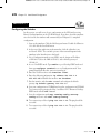
1
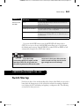
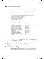
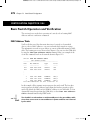
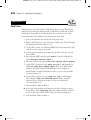
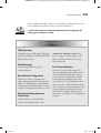
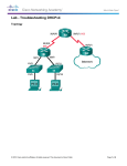
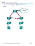
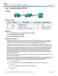
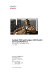
CertPrs8/CCNA® Cisco Certified Network Associate Study Guide/Richard Deal/149728-5/Chapter 12
Blind Folio 357
12
Initial Switch
Configuration
CERTIFICATION OBJECTIVES
ch12.indd 357
12.01
2960 Overview
12.05
12.02
Switch Startup
✓
12.03
Basic Switch Configuration
12.04
Basic Switch Operation and Verification
Q&A
Port Security Feature
Two-Minute Drill
Self Test
3/12/08 4:45:00 PM
CertPrs8/CCNA® Cisco Certified Network Associate Study Guide/Richard Deal/149728-5/Chapter 12
358
Chapter 12: Initial Switch Configuration
T
he 2940, 2955, and 2960 series of switches are Cisco’s current desktop and workgroup
switching solution; they replace the 1900 and 2950 switches. The new switches support
Fast Ethernet and Gigabit Ethernet interfaces. This book, and the CCNA exam, focus
on the end-of-sale 2950 and the newer 2960 switches, but the topics and configuration commands
discussed in this chapter apply to all of Cisco’s Catalyst switches running the Internetwork
Operating System (IOS).
CERTIFICATION OBJECTIVE 12.01
2960 Overview
The 2960 series of switches comes with the LAN-based software image, which
provides advanced quality of service, rate limiting, access control list (ACL), and
many other features. Table 12-1 compares the 2960 switches and their port types and
capacities. The dual-purpose Gigabit Ethernet (GE) port supports a 10/100/1000
port and an SFP (fiber) port, where one of the two ports (not both) can be used. If a
2960 supports dual-ports, this is displayed in the Dual-Purpose column of Table 12-1.
The 2960 series supports an optional external redundant power supply (RPS) that
can be attached to the rear of the chassis.
TABLE 12-1
2960 Models
ch12.indd 358
Switch
10/100 BaseTX
10/100/1000
BaseTX
Dual-Purpose GE
WS-C2960-8TC-L
8
0
1
WS-C2950-24TT-L
24
2
0
WS-C2960-48TT-L
48
2
0
WS-C2950-24TC-L
24
0
2
WS-C2960-48TC-L
48
0
2
WS-C2960G-8TC-L
0
7
1
WS-C2960G-24TC-L
0
20
4
WS-2960G-48TC-L
0
44
4
3/12/08 4:45:01 PM
CertPrs8/CCNA® Cisco Certified Network Associate Study Guide/Richard Deal/149728-5/Chapter 12
2960 Overview
359
Before you begin connecting any cables to your Cisco switches, you should
become familiar with their chassis and interfaces. First, you should understand how
to turn on your Cisco device, what interfaces it has, and the meanings of the various
LEDs (light-emitting diodes) on the chassis. The next few sections cover this in
more depth for the 2960.
2960 Chassis
Figure 12-1 shows illustrations of the front (at top) and rear (at bottom) views of a
2960-24TT switch. For the front view, the ports on the left are the 10/100 BaseTX
ports and the two on the right are the two 10/100/1000 BaseTX ports. For the
10/100 ports, the ports are numbered in the first column, 1 at the top and 2 at the
bottom; in the second column, 3 at the top and 4 at the bottom; and so on. The
front of the chassis contains the MODE button as well as the LEDs.
The rear of the chassis has the management connections. You’ll notice that no
toggle switch is included to turn the switch on or off. To turn the switch on, plug
one end of the power cable into the back of the switch and the other into a power
outlet. To turn the switch off, unplug the power cable from either end. The 2960
supports an RJ-45 console interface, which uses a rollover cable for connectivity to
a terminal or terminal emulation device for console access.
Ports and LEDs
FIGURE 12-1
A 2950-24TT
switch
2960 Front
SYST
RPS
STAT
DUPLX
SPEED
MODE
2960 Rear
RJ-45
console port
ch12.indd 359
Fan exhaust
RPS outlet
Power
3/12/08 4:45:01 PM
CertPrs8/CCNA® Cisco Certified Network Associate Study Guide/Richard Deal/149728-5/Chapter 12
360
Chapter 12: Initial Switch Configuration
TABLE 12-2
2960 SYSTEM
and RPS LEDs
LED
Color
Description
SYSTEM
Green
The system is up and operational.
Amber
The system experienced a malfunction.
Off
The system is powered down.
Green
The RPS is attached and operational.
Amber
The RPS is installed but is not operational. Check the RPS
to ensure that it hasn’t failed.
Flashing
amber
Both the internal power supply and the external RPS are
installed, but the RPS is providing power.
Off
The RPS is not installed.
RPS
2960 LEDs and MODE Button
Remember that if the
SYSTEM LED is amber, the switch is
experiencing a malfunction.
The front of the 2960 chassis has many LEDs
that you can use to monitor the switch’s activity
and performance. At the top-left of the 2960’s
front chassis are the SYSTEM and RPS LEDs.
The colors of these LEDs and their meanings
are shown in Table 12-2.
MODE Button
The meaning of the LED above each port on the front of the 2960’s chassis depends
on the LED’s mode setting. You can change the mode by pressing the MODE button
on the bottom-left side of the chassis front, below the SYSTEM and RPS LEDs. Just
above the MODE button are three port-mode LEDs: STAT, DUPLX, and SPEED. By
default, the STAT LED is lit, indicating that the LEDs above the Ethernet ports refer
to the status of the port. Table 12-3 shows the LED colors and descriptions for the
various port statuses.
If you push the MODE button once, the MODE LED will change from STAT
to DUPLX. The LEDs above each of the ports will reflect the duplex setting of the
associated port. If the LED above the port is off, the port is set to half-duplex; if the
LED is green, the port is set to full-duplex. By pressing the MODE button again,
the MODE LED will change from DUPLX to SPEED. The 2960 supports 10/100
and 10/100/1000 ports. When the mode LED is set to SPEED, the LEDs above the
port refer to the speed at which the port is operating. If the LED is off, the port is
operating at 10 Mbps; if solid green, 100 Mbps; and if blinking green, 1 Gbps.
ch12.indd 360
3/12/08 4:45:02 PM
CertPrs8/CCNA® Cisco Certified Network Associate Study Guide/Richard Deal/149728-5/Chapter 12
Switch Startup
TABLE 12-3
Status Mode and
Port LEDs
361
LED Color
LED Meaning
Green
A powered-up physical layer connection to the device is
attached to the port.
Flashing green
Traffic is entering and/or leaving the port.
Flashing green and amber
An operational problem is occurring with the port—perhaps
excessive errors or a connection problem.
Amber
The port has been disabled manually (shut down), disabled
because it is in a blocking STP state, or disabled because of
a security issue.
Off
No powered-up physical layer connection exists on the port.
If you press the MODE button again, the MODE LED will change back to
STAT. As you can see, the use of the MODE button allows you to cycle through
the different mode settings. If the MODE LED is either DUPLX or SPEED, it will
automatically change back to STAT after 1 minute.
If you don’t have
connectivity through the switch and the
switch port LEDs are all off, make sure
the switch is powered on. Reseat the cable
connectors in their ports. Also check the
cables to make sure they are the correct
type: straight versus cross-through.
CERTIFICATION OBJECTIVE 12.02
Switch Startup
Now that you have a basic understanding of the chassis of the 2960, you are ready to
learn about the bootup process of the switch: this includes the running of hardware
tests, loading the IOS, and finding and applying a configuration file. The following
sections discuss these processes.
ch12.indd 361
3/12/08 4:45:03 PM
CertPrs8/CCNA® Cisco Certified Network Associate Study Guide/Richard Deal/149728-5/Chapter 12
362
Chapter 12: Initial Switch Configuration
Switch Bootup Process
For your initial access to the switch, make sure you plug the rollover cable into the
switch’s console port and the other end into the COM port of your computer. Start
up a terminal emulation program such as HyperTerminal, Tera Term, or PuTTY to
view the command-line interface (CLI) output of the switch. When power is applied
to the 2960, the switch will begin its bootup process. Flash is first validated, and
then the IOS is found, uncompressed, and loaded.
POST is then run to verify that the different components of the switch are
operational. When POST begins, the SYSTEM LED is off. Once POST completes
all testing, and all tests have passed, the SYSTEM LED should turn green. If the
LED is amber, you know that at least one test has failed during POST, which is
usually catastrophic for the switch: in other words, the switch won’t boot up.
Running POST takes about a minute.
Assuming that the POST tests pass, at least the critical ones, the IOS continues
executing. Once the IOS completely loads, a configuration is found and applied
to the switch, and you’ll be presented with the User EXEC prompt, assuming you
are connected to the console port of the switch. An example of the 2960’s bootup
process is shown here:
Base ethernet MAC Address: 00:1c:f6:89:97:00
Xmodem file system is available.
The password-recovery mechanism is enabled.
Initializing Flash...
flashfs[0]: 602 files, 19 directories
flashfs[0]: 0 orphaned files, 0 orphaned directories
.
.
.
flashfs[0]: flashfs fsck took 10 seconds.
...done Initializing Flash.
Boot Sector Filesystem (bs) installed, fsid: 3
done.
Loading "flash:c2960-lanbasek9-mz.122-40.SE/c2960-lanbasek9mz.12240.SE.bin"...@@@@@@@@@@@@@@@@@@@@@@@@@@@@@@@@@@@@@@@@@@@
@@@@@@@@@@@@@@@@@@@@@@@@@@@@@@@@@@@@@@@@@@@@@@@@@@@@@@@@@@@@@@
.
.
.
File "flash:c2960-lanbasek9-mz.122-40.SE/c2960-lanbasek9-mz.
122-40.SE.bin" uncompressed and installed, entry point:
0x3000
ch12.indd 362
3/12/08 4:45:03 PM
CertPrs8/CCNA® Cisco Certified Network Associate Study Guide/Richard Deal/149728-5/Chapter 12
Switch Startup
363
executing...
Restricted Rights Legend
Use, duplication, or disclosure by the Government is
subject to restrictions as set forth in subparagraph
(c) of the Commercial Computer Software – Restricted
Rights clause at FAR sec. 52.227-19 and subparagraph
(c) (1) (ii) of the Rights in Technical Data and Computer
Software clause at DFARS sec. 252.227-7013.
Cisco Systems, Inc.
170 West Tasman Drive
San Jose, California 95134-1706
Cisco IOS Software, C2960 Software (C2960-LANBASEK9-M),
Version 12.2(40)SE, RELEASE SOFTWARE (fc3)
Copyright (c) 1986-2007 by Cisco Systems, Inc.
Compiled Fri 24-Aug-07 01:55 by myl
Image text-base: 0x00003000, data-base: 0x00FC0000
Initializing flashfs...
flashfs[1]: 602 files, 19 directories
flashfs[1]: 0 orphaned files, 0 orphaned directories
flashfs[1]: Total bytes: 32514048
.
.
.
flashfs[1]: Initialization complete....done Initializing
flashfs.
POST: CPU MIC register Tests : Begin
POST: CPU MIC register Tests : End, Status Passed
POST: PortASIC Memory Tests : Begin
POST: PortASIC Memory Tests : End, Status Passed
POST: CPU MIC interface Loopback Tests : Begin
POST: CPU MIC interface Loopback Tests : End, Status Passed
POST: PortASIC RingLoopback Tests : Begin
POST: PortASIC RingLoopback Tests : End, Status Passed
POST: PortASIC CAM Subsystem Tests : Begin
POST: PortASIC CAM Subsystem Tests : End, Status Passed
POST: PortASIC Port Loopback Tests : Begin
POST: PortASIC Port Loopback Tests : End, Status Passed
Waiting for Port download...Complete
ch12.indd 363
3/12/08 4:45:03 PM
CertPrs8/CCNA® Cisco Certified Network Associate Study Guide/Richard Deal/149728-5/Chapter 12
364
Chapter 12: Initial Switch Configuration
This product contains cryptographic features and is subject
to United States and local country laws governing import,
export, transfer and use. Delivery of Cisco cryptographic
.
.
.
cisco WS-C2950-24TT-L (PowerPC405) processor (revision D0)
with 61440K/4088K bytes of memory.
Processor board ID FOC1131W4NR
Last reset from power-on
1 Virtual Ethernet interface
24 FastEthernet interfaces
2 Gigabit Ethernet interfaces
The password-recovery mechanism is enabled.
64K bytes of flash-simulated non-volatile configuration memory.
Base ethernet MAC Address
: 00:1C:F6:89:97:00
Motherboard assembly number
: 73-10390-04
Power supply part number
: 341-0097-02
Motherboard serial number
: FOC11305QDR
Power supply serial number
: AZS113104M2
Model revision number
: D0
Motherboard revision number
: A0
Model number
: WS-C2950-24TT-L
System serial number
: FOC1131W4NR
Top Assembly Part Number
: 800-27221-03
Top Assembly Revision Number
: A0
Version ID
: V03
CLEI Code Number
: COM3L00BRB
Hardware Board Revision Number : 0x01
Switch
Ports
---------*
1
26
Press RETURN to
Model
----WS-C2950-24TT-L
get started!
SW Version
---------12.2(40)SE
SW Image
---------C2960-LANBASEK9-M
I prefer using PuTTY as my management program. It supports COM terminal
emulation, telnet, and SSH functions—and it’s free!
System Configuration Dialog
If no configuration is found, the IOS will run the setup script, commonly called the
System Configuration Dialog. This script asks you questions to help it create a basic
ch12.indd 364
3/12/08 4:45:04 PM
CertPrs8/CCNA® Cisco Certified Network Associate Study Guide/Richard Deal/149728-5/Chapter 12
Switch Startup
365
configuration on the switch. When posing questions, the setup script uses brackets
([ and ]) to indicate default values. Leaving these answers blank (that is, not supplying
an answer) results in the script accepting the value indicated in brackets for the
configuration component. In the script, you can configure the switch’s hostname, set
up a Privilege EXEC password, assign a password for the virtual type terminals (VTYs),
and set up an IP address for a VLAN interface to manage the switch remotely.
If a switch boots up without (System Configuration Dialog) will be
a configuration in NVRAM, the setup script presented to the administrator.
Here’s an example of this script:
Would you like to enter the initial configuration dialog? [yes/no]: yes
At any point you may enter a question mark '?' for help.
Use ctrl-c to abort configuration dialog at any prompt.
Default settings are in square brackets '[]'.
Basic management setup configures only enough connectivity
for management of the system, extended setup will ask you
to configure each interface on the system
Would you like to enter basic management setup? [yes/no]: yes
Configuring global parameters:
Enter host name [Switch]:
The enable secret is a password used to protect access to
privileged EXEC and configuration modes. This password, after
entered, becomes encrypted in the configuration.
Enter enable secret: cisco
The enable password is used when you do not specify an
enable secret password, with some older software versions, and
some boot images.
Enter enable password: boson
The virtual terminal password is used to protect
access to the router over a network interface.
Enter virtual terminal password: sanjose
Configure SNMP Network Management? [no]:
Current interface summary
ch12.indd 365
3/12/08 4:45:04 PM
CertPrs8/CCNA® Cisco Certified Network Associate Study Guide/Richard Deal/149728-5/Chapter 12
366
Chapter 12: Initial Switch Configuration
Interface
Vlan1
FastEthernet0/1
FastEthernet0/2
.
.
.
FastEthernet0/24
GigabitEthernet0/1
GigabitEthernet0/2
IP-Address
unassigned
unassigned
unassigned
OK?
YES
YES
YES
Method
unset
unset
unset
unassigned
unassigned
unassigned
YES unset
YES unset
YES unset
Status
up
down
down
Protocol
down
down
down
down
down
down
down
down
down
Enter interface name used to connect to the
management network from the above interface summary: vlan1
Configuring interface Vlan1:
Configure IP on this interface? [no]: yes
IP address for this interface: 192.168.1.253
Subnet mask for this interface [255.255.255.0] :
Class C network is 192.168.1.0, 24 subnet bits; mask is /24
Would you like to enable as a cluster command switch? [yes/no]: no
The following configuration command script was created:
hostname Switch
enable secret 5 $1$.N.L$t4q9Jw5DTffPTPE.KkKNX/
enable password boson
line vty 0 15
password sanjose
no snmp-server
interface Vlan1
no shutdown
ip address 192.168.1.253 255.255.255.0
!
interface FastEthernet0/1
.
.
.
interface GigabitEthernet0/1
!
interface GigabitEthernet0/2
end
[0] Go to the IOS command prompt without saving this config.
[1] Return back to the setup without saving this config.
[2] Save this configuration to nvram and exit.
Enter your selection [2]: 2
ch12.indd 366
3/12/08 4:45:04 PM
CertPrs8/CCNA® Cisco Certified Network Associate Study Guide/Richard Deal/149728-5/Chapter 12
Basic Switch Configuration
CertCam
ON
THE CD
367
12.01. The CD contains a multimedia demonstration of the bootup process of
a 2950 switch.
At the end of the script, type 2 to accept and activate your changes, as well as
save the configuration to NVRAM. Entering 0 aborts the script and 1 starts the
script over, remembering what you just entered, as the defaults, for the questions you
were just asked.
One problem with this script is that once you answer a question—correctly
or incorrectly—there is no way of going back to the question. To abort the
script, press CTRL-C and start over. To run the script from the CLI without
rebooting the switch, go to Privilege EXEC mode and execute the setup
command.
CERTIFICATION OBJECTIVE 12.03
Basic Switch Configuration
Common IOS configuration tasks for switches and routers, such as assigning a
hostname, setting up passwords for User and Privilege EXEC access, and configuring
hardware characteristics for interfaces (speed and duplexing), were discussed in
Chapter 11. This section addresses how to assign an IP address and default gateway
address to your switch so that you can access it remotely. You’ll also see a quick and
basic initial switch configuration based on the commands in Chapter 11 and this
chapter.
Remember that you don’t have to enable interfaces manually on your
Catalyst switches: they are enabled by default.
IP Address and Default Gateway
If you want to manage your layer 2 switch remotely, you need to assign it IP
addressing information. For example, if you want to telnet or SSH to your switch,
remotely manage it from a web browser or SNMP management station, or back
up and restore configuration files or upgrade the switch, you’ll need to set up IP
ch12.indd 367
3/12/08 4:45:05 PM
CertPrs8/CCNA® Cisco Certified Network Associate Study Guide/Richard Deal/149728-5/Chapter 12
368
Chapter 12: Initial Switch Configuration
addressing information on the switch: an IP address associated with an interface and
a default gateway address. Here’s the configuration you’ll use:
Switch(config)# interface vlan VLAN_#
Switch(config-vlan)# ip address IP_address subnet_mask
Switch(config-vlan)# exit
Switch(config)# ip default-gateway router’s_IP_address
With layer 2 switches such as the 2960, you must go into the VLAN interface
with which you want the IP address to be associated—this will be the management
VLAN in which your administrative PC is located. The System Configuration
Dialog assumes this will be VLAN 1, but you can use any VLAN you want; however,
you must first create the VLAN (see Chapter 13.) Once you’re working in the
VLAN interface, use the ip address command to assign the address and subnet
mask. Next, assign the default gateway: ip default-gateway. This command
is necessary if the switch needs to communicate with other devices, via IP, that are
located in other subnets.
For the switch to access
devices in other VLANs, you need to
assign it an IP address and a default
gateway: use the ip address and ip
default-gateway commands. Hosts
should not use a layer 2 switch’s address
as a default gateway.
Example Configuration
Now let’s pull together the basic configuration tasks from Chapter 11 as well as the
above configuration in a simple example, using the network shown in Figure 12-2:
Switch(config)# hostname Switch-A
Switch-A(config)# line console 0
Switch-A(config-line)# exec-timeout 5 0
Switch-A(config-line)# password consolepass123
Switch-A(config)# exit
Switch-A(config)# line vty 0 15
Switch-A(config-line)# password telnetpass123
Switch-A(config-line)# exec-timeout 5 0
ch12.indd 368
3/12/08 4:45:06 PM
CertPrs8/CCNA® Cisco Certified Network Associate Study Guide/Richard Deal/149728-5/Chapter 12
Basic Switch Configuration
FIGURE 12-2
Simple switch
configuration
example
369
PC-A
10.0.1.10/24
0000.1111.AAAA
PC-B
10.0.1.11/24
0000.1111.CCCC
Switch-A
10.0.1.2/24
1
2
3
Router-A
FA0/0:
10.0.1.1/24
0000.1111.BBBB
Switch-A(config-line)# login
Switch-A(config-line)# exit
Switch-A(config)# enable secret secretpass123
Switch-A(config)# service password-encryption
Switch-A(config)# banner motd $
This is a private system and only authorized individuals
are allowed!
All others will be prosecuted to the fullest extent of the law!
$
Switch-A(config)# interface vlan 1
Switch-A(config-vlan)# ip address 10.0.1.2 255.255.255.0
Switch-A(config-vlan)# exit
Switch-A(config)# ip default-gateway 10.0.1.1
Switch-A(config)# end
Switch-A# copy running-config startup-config
In this example, the switch was given a hostname (Switch-A), passwords for the
console, VTYs, Privilege EXEC mode, a login banner, an IP address for VLAN 1,
and a default gateway; plus, I saved the switch’s configuration to NVRAM.
CertCam
ON
THE CD
ch12.indd 369
12.02.The CD includes a multimedia demonstration of placing a basic
configuration on a 2950 switch.
3/12/08 4:45:08 PM
CertPrs8/CCNA® Cisco Certified Network Associate Study Guide/Richard Deal/149728-5/Chapter 12
370
Chapter 12: Initial Switch Configuration
EXERCISE 12-1
Configuring the Switches
ON THE CD
In this exercise, you will create a basic configuration on the 2950 switches using
Boson’s NetSim simulator on the CD-ROM switch. If you have closed the simulator
since the last lab, the simulator will automatically load Chapter 11’s completed
configuration.
1. Start up the simulator. Click the LabNavigator button. Double-click Exercise
12-1 and click the Load Lab button.
2. At the top of the application in the menu bar, click the eSwitches icon
and choose 2950-1. You can find a picture of the network diagram for the
simulator in the Introduction to this book.
3. Go to Configuration mode on your 2950-1 switch. Assign an IP address
of 192.168.1.2/24 to the 2960 in VLAN 1, with a default gateway of
192.168.1.1.
4. Access User EXEC mode. Type enable to go to Privilege EXEC mode and
then type configure terminal to access Configuration mode. Your
prompt should look like this: Switch(config)#.
5. Enter the VLAN interface with interface vlan1.
6. Enter the addressing information: ip address 192.168.1.2
255.255.255.0. Enable the interface: no shutdown.
7. Exit the interface with the exit command and configure the default
gateway: ip default-gateway 192.168.1.1.
8. Save your configuration to NVRAM and view the configuration in NVRAM.
Test connectivity by pinging the Host-1 and Host-2 PCs. Return to Privilege
EXEC mode with the end command.
9. Save the configuration with copy running-config startupconfig and view it with show startup-config.
10. Test connectivity to Host-1: ping 192.168.1.10. The ping should be
successful.
11. Test connectivity to Host-2: ping 192.168.1.11. The ping should be
successful.
ch12.indd 370
3/12/08 4:45:09 PM
CertPrs8/CCNA® Cisco Certified Network Associate Study Guide/Richard Deal/149728-5/Chapter 12
Basic Switch Configuration
371
Now configure the 2950-2 switch. The commands are the same, except use
the appropriate configuration information: the IP address is 192.168.1.3/24. Test
connectivity to the Host-1 PC and 2950-1 switch.
1. Click the eSwitches icon in the toolbar and choose 2950-2.
2. On the 2950-2 switch, access User EXEC mode, and then enter the
following: enable, configure terminal, interface vlan1, ip
address 192.168.1.3 255.255.255.0, no shutdown, exit,
ip default-gateway 192.168.1.1, end, copy runningconfig startup-config, and show startup-config. Make sure
you configured the right IP address.
3. Test connectivity by pinging Host-1 and the 2950-1 switch: ping
192.168.1.10 and ping 192.168.1.2. The pings should be
successful.
Now configure the 2950-3 switch. The commands are the same, except use
the appropriate configuration information: the IP address is 192.168.3.2/24. Test
connectivity to the 2600-1 and Host-4.
1. Click the eSwitches icon in the toolbar and select 2950-3.
2. On the 2950-3 switch, access User EXEC mode, and then enter the
following: enable, configure terminal, interface vlan1, ip
address 192.168.3.2 255.255.255.0, no shutdown, exit,
ip default-gateway 192.168.3.1, end, copy runningconfig startup-config, and show startup-config. Make sure
you configured the right IP address.
3. Test connectivity by pinging the Host-3 and Host-4 PCs: ping
192.168.3.10 and ping 192.168.3.11. The pings should be
successful.
Now you should be comfortable with the basic configuration of the Catalyst IOS
switches.
ch12.indd 371
3/12/08 4:45:09 PM
CertPrs8/CCNA® Cisco Certified Network Associate Study Guide/Richard Deal/149728-5/Chapter 12
372
Chapter 12: Initial Switch Configuration
CERTIFICATION OBJECTIVE 12.04
Basic Switch Operation and Verification
This section focuses on the basic operations of a switch, such as learning MAC
addresses and basic verification commands.
MAC Address Table
You’ll recall that one of the three main functions of a switch is to learn which
devices—that is, MAC addresses—are associated with which interfaces or ports.
This information is stored in a port address, or content addressable memory (CAM),
table. The learning process was discussed in Chapter 4. You can view the CAM table
by using the show mac-address-table command. Here is an example of the
use of this command, based on the network shown in Figure 12-2:
Switch> show mac address-table
Mac Address Table
-----------------------------------------Vlan
Mac Address
Type
Ports
--------------------All
0000.0000.0001
STATIC
CPU
All
0000.0000.0002
STATIC
CPU
.
.
.
1
0000.1111.AAAA
DYNAMIC
FA0/1
1
0000.1111.CCCC
DYNAMIC
FA0/2
1
0000.1111.BBBB
DYNAMIC
FA0/3
Total Mac Addresses for this criterion: 12
In this example, all the STATIC entries represent the switch itself. The last three
entries represent the MAC addresses learned from the first three interfaces of the
switch. By default, the 2960 can fit 8192 MAC addresses in its CAM table. To clear
dynamically learned entries from the CAM table, use the clear mac-addresstable command from Privilege EXEC mode.
You shouldn’t see a broadcast or multicast addresses in the port address table
since these are not seen as source addresses in frames and thus aren’t learned
by the switch.
ch12.indd 372
3/12/08 4:45:10 PM
CertPrs8/CCNA® Cisco Certified Network Associate Study Guide/Richard Deal/149728-5/Chapter 12
Basic Switch Operation and Verification
Be familiar with the output
of the show mac-address-table
command. If a destination MAC address is
373
not in the table (unknown), the switch will
flood it.
Static MAC Addresses
In addition to having the switches learn MAC addresses dynamically, you can
manually create static entries. You might want to do this for security reasons. If a
user moves her connection from one switch port to another, her traffic won’t be
forwarded correctly if you had statically configured her address to the old port. For
traffic to flow correctly again, you would have to change the old entry to reflect the
user’s new interface. You may want to do this to ensure that the user doesn’t unplug
her connection from one port and connect it to another port, where the user might
have access to more networking resources.
Unlike dynamic entries in a CAM table, static entries do not age out. This is true
even if you reboot the switch (assuming your configuration has been saved). Also,
if you have a static entry for a device and you move that device to a different port,
even though the switch will see the change, the static entry will always override the
learning function of the switch.
On a 2960 switch, use the following command to create a static entry in the
CAM table:
Switch(config)# mac-address-table static MAC_address
vlan VLAN_#
interface type module/port_#
In addition to specifying the MAC address of the device and the interface where the
device is located, you must also specify the VLAN in which the device is located
(see Chapter 13). Use the show mac-address-table command to view your
new entries. To remove a static entry from the CAM table, preface the preceding
command with the no parameter.
Statically configuring MAC addresses on the switch is not very common today.
If configured, static entries are typically used for network devices, such as
servers and routers. If you are concerned about controlling what user device is
located from which interface on a switch, either use the port security feature
or 802.1x authentication.
ch12.indd 373
3/12/08 4:45:10 PM
CertPrs8/CCNA® Cisco Certified Network Associate Study Guide/Richard Deal/149728-5/Chapter 12
374
Chapter 12: Initial Switch Configuration
EXERCISE 12-2
ON THE CD
CAM Tables
The following sections deal with the CAM table and port security. This exercise
will help you become more familiar with the CAM table on a 2950 switch. You’ll
perform this lab using Boson’s NetSim simulator. You can find a picture of the
network diagram for the simulator in the Introduction of this book.
1. Start up the simulator and click the Lab Navigator button.
2. Double-click Exercise 12-2 and click the Load Lab button. This will load the
lab configuration based on Exercise 12-1.
3. On the 2950-1 switch, access Privilege EXEC mode and examine the CAM
table. If any entries appear, clear them.
4. At the top of the simulator in the menu bar, click the eSwitches icon and
choose 2950-1.
5. Enter Privilege EXEC mode by typing enable. View the CAM table by
typing show mac-address-table.
6. Clear the CAM table by typing clear mac-address-table dynamic.
7. On the 2950-1, ping Host-1: type ping 192.168.1.10. Examine the
CAM table: show mac-address-table. What is the MAC address
of Host-1? The MAC address will be different for each computer on
which NetSim is installed. With what interface is it associated (should be
fastethernet0/3)?
8. On the 2950-1, ping Host-2: type ping 192.168.1.11. Examine
the CAM table: show mac-address-table. What is the MAC
address of Host-2? With what interface is it associated (should be
fastethernet0/4)?
9. Verify the MAC address on Host-1.
10. At the top of the simulator in the menu bar, click the eStations icon and
choose Host-1. Enter ipconfig /all and compare the MAC address of
the PC to that learned by the 2950-1 switch on fastethernet0/3.
11. Verify the MAC address on Host-2.
ch12.indd 374
3/12/08 4:45:11 PM
CertPrs8/CCNA® Cisco Certified Network Associate Study Guide/Richard Deal/149728-5/Chapter 12
Port Security Feature
375
12. At the top of the simulator in the menu bar, click the eStations icon and
choose Host-2. Enter ipconfig /all and compare the MAC address of
the PC to that learned by the 2950-1 switch on fastethernet0/4.
You should be more comfortable with the CAM table on Cisco switches.
CERTIFICATION OBJECTIVE 12.05
Port Security Feature
Port security is a switch feature that allows you to lock down switch ports based on
the MAC address or addresses associated with the interface, preventing unauthorized
access to a LAN. For example, if MAC address 0001.001c.dddd is supposed to be
off of fa0/1, but it is seen off of fa0/2, this would be considered a security violation.
Or, if more addresses are seen off the interface than you allow, this would also be
considered a violation. As an administrator, you control what should happen when
a violation occurs, be it generating a notification about the issue, dropping traffic
for the MAC address that caused the violation,
or completely disabling the port where the
violation occurred.
The port security feature will not work
Port security and/or
on trunk ports (Chapter 13), switch port
802.1x can be used lock down ports on a
analyzer ports (SPANs), and EtherChannel
switch, preventing unauthorized access to
ports (Chapter 14). However, it is compatible
your LAN network.
with 802.1x (Chapter 5) and Voice VLANs
(Chapter 13).
Port Security Configuration
Starting in IOS 12.1(6)EA2, Cisco standardized how port security is configured on
its switches. The entire configuration is performed on an interface-by-interface basis
by using the switchport commands:
switch(config)# interface fastethernet|gigabit 0/port_#
switch(config-if)# switchport mode access
switch(config-if)# switchport access vlan VLAN_#
ch12.indd 375
3/12/08 4:45:12 PM
CertPrs8/CCNA® Cisco Certified Network Associate Study Guide/Richard Deal/149728-5/Chapter 12
376
Chapter 12: Initial Switch Configuration
switch(config-if)# switchport port-security
switch(config-if)# switchport port-security maximum value
switch(config-if)# switchport port-security violation
protect|restrict|shutdown
switch(config-if)# switchport port-security mac-address MAC_address
switch(config-if)# switchport port-security mac-address sticky
Be familiar with configuring
port security with the switchport
port-security commands (enabling it,
limiting the MAC addresses, violation mode,
and sticky learning).
First, you must enter the appropriate interface where you want to set up restricted
security. The first command, switchport mode access, defines the interface
as a host (access) port instead of a trunk port (trunking is explained in Chapter 13).
The second command places the access port in a specific VLAN (also discussed
in Chapter 13). The third command on the
interface, switchport port-security,
enables port security (it is disabled, by default).
The fourth command, switchport portSet the maximum to
security maximum, specifies the maximum
1 address for an interface to prevent
number of devices that can be associated with
spoofing of MAC addresses: only one
the interface. This defaults to 1 and can range
MAC address is learned.
from 1 to 132.
The fifth command on the interface specifies what should occur if a security
violation occurs—the MAC address is seen connected to a different port. Three
options are possible:
When the number of secure addresses reaches the maximum
number allowed, any additionally learned addresses will be dropped. This
applies only if you have enabled the sticky option, discussed in the next
paragraph.
■ protect
■ restrict
Causes the switch to generate a security violation alert.
Causes the switch to generate an alert and to disable the
interface. The only way to re-enable the interface is to use the no shutdown
command. This is the default violation mode if you don’t specify the mode.
■ shutdown
ch12.indd 376
3/12/08 4:45:12 PM
CertPrs8/CCNA® Cisco Certified Network Associate Study Guide/Richard Deal/149728-5/Chapter 12
Port Security Feature
377
When an interface is disabled because of a violation with port security, you
can reset the interface with this Configuration mode command: errdisable
recovery cause psecure-violation.
The last two commands in the preceding code listing affect how the switch learns
the secure MAC addresses on the interface. The first one has you specify the exact
MAC address that is allowed to be associated with this interface—this is statically
defining the MAC addresses allowed off of the port. The second command uses the
sticky feature, which allows the switch to dynamically learn the MAC address(es)
associated with the interface and convert these dynamic entries to static entries.
The interface will learn MAC addresses only up to the maximum configured value
for that interface. After you save your configuration (copy running-config
startup-config), and when you reboot your switch, the sticky-learned
addresses appear as statically secure addresses. Basically, sticky learning lets you
avoid having to configure the MAC addresses associated with the interface.
If you don’t statically define the MAC addresses or use sticky learning to learn
them with port security, dynamic learning is used. Dynamic learning is similar to
sticky learning in that the switch will learn the MAC addresses dynamically off of
the interface up to the maximum defined; however, unlike sticky learning, these
addresses are not saved: every time the switch boots up or the interface is reset, the
MAC addresses are relearned for the interface.
Sticky learning allows a
switch to dynamically learn MAC addresses
up to the maximum allowed for the
interface, which is then automatically saved
in the switch’s configuration.This is used
as the most efficient way of learning the
MAC addresses connected to the switch.
Statically configuring a MAC address is
typically used for network devices such as
servers and routers.
Port Security Verification
To verify your configuration, use the show port-security interface
command:
switch# show port-security interface fa0/2
Port Security : Enabled
Port status : SecureUp
Violation mode : Restrict
Maximum MAC Addresses : 1
Total MAC Addresses : 1
ch12.indd 377
3/12/08 4:45:12 PM
CertPrs8/CCNA® Cisco Certified Network Associate Study Guide/Richard Deal/149728-5/Chapter 12
378
Chapter 12: Initial Switch Configuration
Configured MAC Addresses : 1
Aging time : 0 mins
Aging type : Absolute
SecureStatic address aging : Disabled
Security Violation count : 0
In this example, you can see that port security is enabled, the violation mode is restrict,
the maximum number of MAC addresses that can be connected to the port is 1, and
one MAC address has to be statically configured for the port. At the bottom of the
output, you can see that no security violations have occurred on the port.
To see an overview configuration of port security on your switch, use the show
port-security command:
switch# show port-security
Port
MaxSecureAddr CurrentAddr SecurityViolation Security Action
(Count)
(Count)
(Count)
-----------------------------------------------------------------Fa0/1
10
10
0
Shutdown
Fa0/2
1
1
0
Restrict
.
.
.
-----------------------------------------------------------------Total Addresses in System :21
Max Addresses limit in System :6176
In this example, 10 MAC addresses can be learned off of FA0/1, 10 have been
learned, and the violation mode is shut down; but currently no violations have
occurred on the port.
To see the MAC addresses statically defined or dynamically learned with port
security, use the show port-security address command:
IOS# show port-security address
Secure Mac Address Table
----------------------------------------------------------Vlan Mac Address
Type
Ports Remaining Age
(mins)
---- -------------- ----------------- ----- ------------1
0001.0001.0011 SecureDynamic
Fa0/1
15 (I)
1
0001.0001.0022 SecureDynamic
Fa0/1
15 (I)
1
0001.0001.1144 SecureConfigured Fa0/1
.
.
.
---------------------------------------------------------------Total Addresses in System :21
Max Addresses limit in System :6176
ch12.indd 378
3/12/08 4:45:13 PM
CertPrs8/CCNA® Cisco Certified Network Associate Study Guide/Richard Deal/149728-5/Chapter 12
Port Security Feature
379
In this example, three MAC addresses are off of FA0/1, where the first two were
learned dynamically and the last one was statically configured.
CertCam
ON
THE CD
12.03. The CD contains a multimedia demonstration of configuring and
verifying port security on a switch.
INSIDE THE EXAM
2960 Overview
Be familiar with the LEDs on the 2900 series
switches, including the SYSTEM and PORT
LEDs and their colors.
Switch Startup
Understand when the setup script
automatically runs.
Basic Switch Configuration
Be able to put a basic configuration on a
switch: hostname, passwords, assigning an IP
address to a VLAN interface, and assigning a
default gateway address. Know when you must
configure a default gateway address on a switch.
Basic Switch Operation and
Verification
(show mac-address-table) and
how to compare incoming frames to the
table to determine how the switch will
forward the frame.
Port Security Feature
Of the five sections in this chapter, this
section is probably the most emphasized on
the exam. Understand why port security is
used as well as the commands to configure
it. Know why the maximum addresses for
an interface is set to 1. Remember the three
violation modes, as well as what they do. Be
able to compare and contrast dynamic, sticky,
and static learning and when each is used.
And be able to configure this feature on a
switch, since you might see it on a simulation
question!
Understand how to view the MAC
addresses in the MAC address table
ch12.indd 379
3/12/08 4:45:13 PM
CertPrs8/CCNA® Cisco Certified Network Associate Study Guide/Richard Deal/149728-5/Chapter 12
380
Chapter 12: Initial Switch Configuration
CERTIFICATION SUMMARY
This chapter focused on basic configuration tasks specific to Cisco Catalyst switches.
The 2960 switches were introduced, including the meaning of their LEDs and the
use of the MODE button. When a switch boots up, it runs POST, loads the IOS,
and then loads its configuration. If the IOS can’t find a configuration file, it runs the
System Configuration Dialog.
To manage the switch remotely, minimally it will need an IP address associated
with a VLAN (interface vlan and ip address) and a default gateway
address (ip default-gateway). To view the MAC addresses the switch learns,
use the show mac-address-table command.
Port security can be used to prevent unauthorized access to a LAN. Addresses
can be learned dynamically (not saved), using sticky learning (saved), or statically
configured. A violation occurs when more MAC addresses are off of an interface
than are specified or when a MAC address is seen off of a different interface than
expected. Violation modes are restrict, protect, and shutdown. Port security can
be configured only on access (non-trunk) ports with the switchport portsecurity commands.
ch12.indd 380
3/12/08 4:45:13 PM
CertPrs8/CCNA® Cisco Certified Network Associate Study Guide/Richard Deal/149728-5/Chapter 12
Two-Minute Drill
✓
381
TWO-MINUTE DRILL
2960 Overview
❑ The 2960 switches support Fast Ethernet and/or Gigabit Ethernet interfaces.
❑ The SYSTEM LED will be amber if the switch experiences a malfunction.
❑ The MODE button is used to change the meanings of the port LEDs.
❑ If a port LED is flashing amber/green, there is an operational problem with
the port; if it is amber, the port has been disabled: shutdown, STP blocking,
or port security violation.
Switch Startup
❑ When a switch boots up, POST is run, the IOS is found and loaded, and the
configuration is found and loaded.
❑ If a configuration file cannot be found when booting up, the System
Configuration Dialog questions can be answered to place a basic
configuration on the switch.
Basic Switch Configuration
❑ An IP address can be assigned to a VLAN interface on a switch for accessing
it remotely via telnet or SSH, or to back up its configuration or upgrade its
IOS using the ip address command.
❑ The ip default-gateway command assigns a router address the switch
should use to access other subnets.
Basic Switch Operation and Verification
❑ The show mac-address-table command displays the port address
table of the switch.
Port Security Feature
❑ Port security is used to prevent unauthorized access to a LAN on access
interfaces (non-trunk connections).
❑ The switchport port-security commands are used to configure it.
ch12.indd 381
3/12/08 4:45:14 PM
CertPrs8/CCNA® Cisco Certified Network Associate Study Guide/Richard Deal/149728-5/Chapter 12
382
Chapter 12: Initial Switch Configuration
❑ The defaults for port security are learning one MAC address on the interface
with a violation mode of shutdown.
❑ Sticky learning allows a switch to dynamically learn which MAC addresses
are associated with an interface, as well as saving these in the running
configuration of the switch.
ch12.indd 382
3/12/08 4:45:14 PM
CertPrs8/CCNA® Cisco Certified Network Associate Study Guide/Richard Deal/149728-5/Chapter 12
Self Test
383
SELF TEST
The following Self Test questions will help you measure your understanding of the material presented
in this chapter. Read all the choices carefully, as there may be more than one correct answer. Choose
all correct answers for each question.
2960 Overview
1. The SYSTEM LED will be __________ if the switch has experienced a malfunction.
A.
B.
C.
D.
green
off
amber
red
2. Two PCs are connected to a switch configured in the same subnet, but they can’t ping each
other. 100BaseTX is used for connectivity. What would not indicate a problem?
A.
B.
C.
D.
The PORT LED is off on one of the two PCs’ switch port connections.
The PORT LED is amber on one of the two PCs’ switch port connections.
The SYSTEM LED is off.
The MIC connectors on the Ethernet cables are not seated correctly in the switch ports.
Switch Startup
3. Which of the following is not asked for during the System Configuration Dialog script?
A.
B.
C.
D.
Enabling interfaces
Default gateway address
VLAN interface to use for management functions
Enable secret password
Basic Switch Configuration
4. In which configuration mode is the default gateway address configured for a switch?
A.
B.
C.
D.
Interface
Line
Global
Port
5. Your switch is in the management subnet (192.168.1.0/25). The switch should have the second
to the last valid host address in the subnet in the management VLAN, which is VLAN 5. The
router in the subnet uses the last valid host address in the subnet, which is the switch’s default
gateway. Configure the switch to allow it to reach other subnets.
ch12.indd 383
3/12/08 4:45:15 PM
CertPrs8/CCNA® Cisco Certified Network Associate Study Guide/Richard Deal/149728-5/Chapter 12
384
Chapter 12: Initial Switch Configuration
Basic Switch Operation and Verification
6. Enter the switch command that allows you to see the contents of the port address
table: __________.
7. Examine the following MAC address table on a switch. What will happen if a switch sees
a frame with a destination MAC address of 0000.1111.DDDD?
Switch>
Vlan
---1
1
1
A.
B.
C.
D.
show mac address-table
Mac Address
Type
-------------0000.1111.AAAA
DYNAMIC
0000.1111.CCCC
DYNAMIC
0000.1111.BBBB
DYNAMIC
Ports
----FA0/1
FA0/2
FA0/3
Flood it
Drop it
Forward it out FA0/1
Forward it out of FA0/1 and FA0/2
Port Security Feature
8. Which switch feature is used to prevent unauthorized access to a LAN?
A.
B.
C.
D.
Port security
Port security and 802.1Q
VTY passwords
Enable password
9. Which of the following is not a default configuration for port security?
A.
B.
C.
D.
1 MAC address per interface
Violation mode shutdown
Sticky learning
Disabled by default
10. What learning mode should you use to associate a server with a switch port when port security
is enabled?
A.
B.
C.
D.
ch12.indd 384
Dynamic
Automatic
Sticky
Static
3/12/08 4:45:15 PM
CertPrs8/CCNA® Cisco Certified Network Associate Study Guide/Richard Deal/149728-5/Chapter 12
Self Test Answers
385
SELF TEST ANSWERS
2960 Overview
✓ C. The SYSTEM LED will be amber if the switch has experienced a malfunction.
1. ®
®
˚ A is incorrect because green indicates that the switch is operational. B is incorrect because
the LED is off when the switch is turned off. D is not a valid color for the system LED.
✓ D. 100BaseTX uses RJ-45 connectors, not MIC connectors. MIC connectors are used for
2. ®
fiber connections.
®
˚ A, B, and C would indicate a problem and are thus incorrect answers.
Switch Startup
✓ A. Enabling the interfaces is not asked for during the System Configuration Dialog script:
3. ®
interfaces are enabled by default on Cisco switches.
®
˚ B, C, and D are asked for and are thus incorrect answers.
Basic Switch Configuration
✓ C. The ip default-gateway command is a Global configuration mode command.
4. ®
®
˚ A is incorrect because the Interface mode is used to assign an IP address to a VLAN
interface. B is incorrect because Line mode is used to restrict User EXEC access to the switch.
D is a nonexistent configuration mode.
✓ Here is how to configure the switch to allow it to reach other subnets:
5. ®
interface vlan 5
ip address 192.168.1.125 255.255.255.128
exit
ip default-gateway 192.168.1.126
Notice that the subnet mask is not /24, but /25!
Basic Switch Operation and Verification
✓ show mac-address-table allows you to see the contents of the port address table.
6. ®
✓ A. Unknown unicast destination MAC addresses are flooded.
7. ®
®
˚ B is true of routers, not switches. C and D are incorrect because the frame is flooded since
the destination is unknown.
ch12.indd 385
3/12/08 4:45:16 PM
CertPrs8/CCNA® Cisco Certified Network Associate Study Guide/Richard Deal/149728-5/Chapter 12
386
Chapter 12: Initial Switch Configuration
Port Security Feature
✓ A. Port security is used to prevent unauthorized access to a LAN.
8. ®
®
˚ B is incorrect because 802.1Q is a VLAN trunking protocol. C and D are used to restrict
access to the switch, not to the LAN for which the switch provides connectivity.
✓ C. Dynamic, not sticky, learning is the default.
9. ®
®
˚ A, B, and D are defaults and thus incorrect.
✓ D. You should statically define MAC addresses of servers and routers when using port
10. ®
security.
®
˚ A and C are used for user ports. B is a nonexistent learning mode.
ch12.indd 386
3/12/08 4:45:16 PM