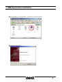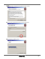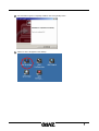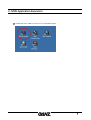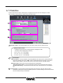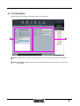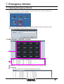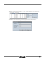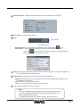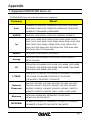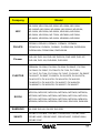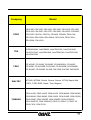
1
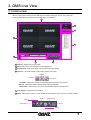
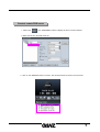
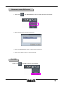
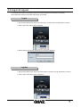
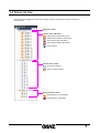
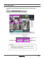
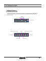
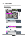
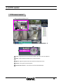
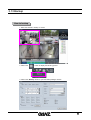
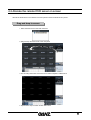
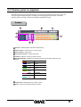
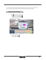
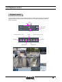
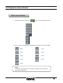
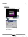
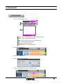
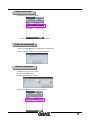
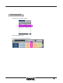
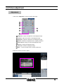
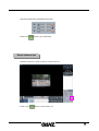
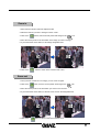
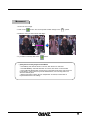
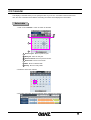
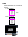
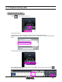
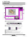
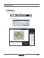
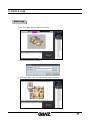
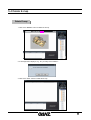
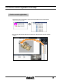
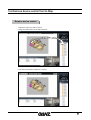
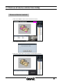
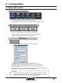
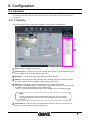
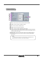
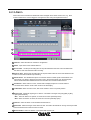
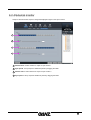
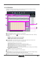
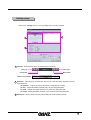
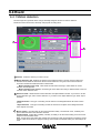
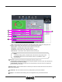
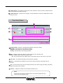
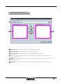
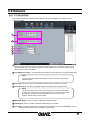
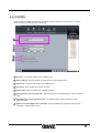
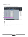
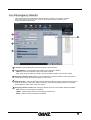
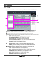
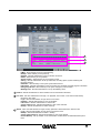
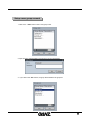
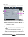
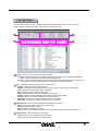
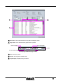
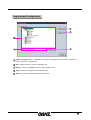
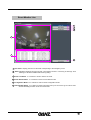
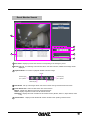
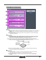
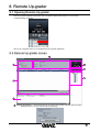
GMS MANUAL
Before
Before Setting
Setting
What
WhatisisGMS?
GMS?
GMS is an integrated security management system that provides a useful solution for
central monitoring station operation.
Minimum
MinimumSystem
SystemSpecifications
Specifications
►CPU
: P-4 or higher than Celeron 1.5GHz
►MEMORY : 256MB or more
►VGA CARD : AGP 64MB or more
►HDD
: Over 100 MB available space
►O/S
: Windows 2000 or Windows XP Professional
►DirectX
: V9.0 or higher
Contents
Contents
After purchasing the GMS program, make sure that the following contents are included.
GMS software
User’s manual
Table
Table of
of Contents
Contents
1. GMS Application Installation………..……………………………………………………………………….6
2. GMS Application Execution….………………………………………………………………………………9
3. GMS Live View.………………………………………………………………………………………………………10
3.1 Initial screen…..…………………………………………………………………………………………10
3.2 Remote DVR server connection ……….………….……………………………………………………………12
3.3 Login-in & Log-out……………………………………………………………………………………………17
3.4 Server list tree………………………………………………………………………………………………18
3.5 Display live screen………………………………………………………………………………………..19
3.6 Screen division….……………………………………………………………………………………….21
3.7 Full-screen enlargement….……….………………………………………………………………………..22
3.8 2Way Audio….……….…………………………………………………………………………………..23
3. 9 T imeline panel..………………..……………………………………………………………………24
3.10 Playback panel..………………..………………………………………………………………………………22
3.11 1 Channel playback….……………..……………………………………………………………………………28
3.12 PTZ control…………………….………………………………………………………………………………29
3.13 Backup…..………………………………………………………………………………….…………………30
4. GMS Search……………………………………………………………………………………………………34
4.1 Playback recorded data……...………..…………………………………………………………………………34
4.2 Allocate remote DVR server on screen ………………………………………………………………35
4.3 Timeline panel on playback ……….……………………………………………………………………………35
4.4 Playback control……………….…………………………………………………………………………………38
4.5 Playback screen division………………………………………………………………………………………39
4.6 Printing………..……………………………………………………………………………………………………40
4.7 Bookmark………………………………………………………………………………………….……………..42
4.8 Picture adjustment ………………………………………………………………………………..…………..45
4.9 Calendar ……………….……………………………………….………………………………………………49
4.10 Event…………………………………………………………………………………………………………….50
4.11 Playback Backup data……………………………………………………………………………………….51
5. GMS E-map….………………………………………………………………………………………………………52
5.1 Display E-map …………..………………………………………………………………………………..52
5 . 2 A d d E - m a p . . … … … … … … … … … … … … … … … … … … … … … … … … … … … … … … … … … .. 53
5. 3 Edit E-map ……………………………………………………………………………………………54
5.4 Delete E-map.....………………………………………………………………………………………….55
5.5 Device control registration to E-map ……………………………………………………………………56
5.6 Remove device control from E-map ……..…….……………………………………………………….57
5.7 Remove all device controls from E-map ..………………………………………………………………….58
5.8 Live screen output ……………………………………………………………………………………………59
6. Configuration………………………………………………………………………………………………… 60
6.1 Basic Menu Parts……………………………………………………………………………………………60
6.2 Hardware……………………………………………………………………………………………………61
6.2.1 Camera………………………………………………………………………………………………………..61
6.2.2 Audio……………………………..…………………………………………………………………………66
6.2.3 Alarm………………..……..………………………………………………………………………………67
6.2.4 External Monitor…………….………………………………………………………………………………68
4
6.3 Recording………………………………………………………………………………………………………69
6.3.1 Recording…………………………………………………………………………………69
6.3.2 Schedule…………………………………………………………………………………70
6.4 E vent ……………………………………………………………………………………………………74
6. 4. 1 Motion Detect ion ………………………………………………………………………………74
6.4.2 Emergency ………………..…………………………………………………………………77
6.4.3 Video Loss……………………………………………………………………………………78
6. 4 . 4 E-ma i l N oti ce… … …… … ………………………………………………………………………79
6.5 Backup………………………………………………………………………………………………………… 81
6.6 Network ……………………………………………………………………………………………………83
6.6.1 Connection……….…………….………………………………………………………………………83
6.6.2 DDNS……..………………….………………………………………………………………………84
6.6.3 Stream Control……………….………………………………………………………………………85
6.6.4 Emergency Monitor………….………………………………………………………………………86
6.7 System …………………………………………………………………………………………………… 87
6.7.1 User……….…………………………………………………………………………………………87
6.7.2 Setting………………………………………………………………………………………………95
6.7.3 Date/Time …………………………………………………………………………………………100
6.7.4 Information…………………………………………………………………………………………101
7. Emergency Monitor….……………………………………………………………………………………………102
7.1 Opening Emergency Monitor ……………..…………………………………………………………………..102
7.2 Emergency Monitor Screen..……………………………..…………………………………………………..102
8. Event Monotor….……………………………………………………………………………………………104
8.1 Opening Event Monitor ……………..………………………………………………..…………………..104
8.2 Event Monitor screen..……………………………..……………………………………………………..104
9. Remote Up-grader….……………………………………………………………………………………………109
9.1 Opening Remote Up-grader……………..………………………………………………..…………………..109
9.2 Remote Up-grader screen..…………………………..……………………………………………………..109
Appendix
1. Supported CD/DVD-RW Drive List …………..………………………………………………………………….111
5
1. GMS Application Installation
1 Insert the GMS CD and double click on “setup.exe” to run the setup program.
2
Click on the [Next] button.
6
3
Check the box “I accept this License Agreement” and click on [Next].
4
Enter the path to install the GMS program and click on the [Next] button.
5
This will start the installation process.
7
6
After the GMS Program is completely installed, click on the [Finish] button.
7
“GMS Live View” will appear on the desktop.
8
2. GMS Application Execution
1
Double click on the “GMS Live View” icon to run the GMS Program.
9
3. GMS Live View
3.1 Initial screen
GMS Live View offers functions such as real time DVR remote viewing and control. The system user
interface is illustrated below. Each element is described in the following:
1
5
6
2
7
4
3
8
9
1 Title bar : Displays the program name.
2 View panel : Live and recorded pictures are display here.
3 Display panel : Multi screen splits, sequence and Full screen display.
4 Tool bar : Live Mode, Refresh, 2Way Audio, Alarm in Full screen.
Refresh
Live Mode
2 Way Audio
Live Mode : Returns any camera in 1 channel playback mode back to live mode.
Refresh : Updates the timeline with the most recent recorded data.
2 Way Audio : Select to use 2 way audio communication between GMS and DVR.
5 Time display : Displays the logo and time.
6 Menu : Event Monitor, Search, E-map, Backup, System settings, Remote server connection possible.
Search
Event Monitor
E-Map
System setup
Server
Backup
10
7 Server list : Shows resource information on the camera, alarm-in and alarm-out for each server.
8 Timeline panel : Displays the recording time of the selected channel.
The recorded time is shown in the graph (24-hour clock).
9 Play tab/PTZ tab : The play tab features the normal/reverse play buttons.
The PTZ tab features the PTZ camera control buttons.
11
3.2 Remote DVR server connection
GMS Live View allows you to connect and manage all the DVR servers in the network.
Add
AddDVR
DVRserver
servergroup
group
1.When you add or connect the remote DVR server, click on the
then be displayed as shown below.
button. It will
2. Click on the “Connection” button to open Server Connect.
3. Enter the group name.
4. Click on the “Add” button to add the group to the server list.
12
Add
AddDVR
DVRremote
remoteserver
server
1. Select the group to be registered.
2. Enter the server connect information.
d
e
a
b
c
a Remote DVR server list : Displays the registered group and server list .
b Import : Imports server connect information from the other DVR.
c Export : Exports server connect information to another DVR or the outside DVR.
d Group : Displays the group name or can be changed to another group.
e Name : Displays the server name or a server name can be entered here to add a new
connect server.
13
p
f
g
h
i
j
m
j
k
n
o
p
f Server Type : Select the server type according to the DVR type.
g Network Type : Select the network type.
h Address : Enter the IP address or domain name of the DVR server to connect.
i
Port : Enter the network port number to communicate with the GMS and DVR
servers.
j
Upgrade Port : Input the network port number by which to upgrade DVR software.
k ID : Enter the administrator ID of the DVR server.
l
Password : Enter the password of the DVR server.
m Auto Login : Check to log-in automatically when GMS is started.
n Add : Click on the “Add” button to add a group or server.
o Update : Click on the “Update” button to update revised server information.
p Del : Click on the “Del” button to delete the server from the server list.
q
Connect : Click on the “Connect” button to connect to the selected DVR server.
3. Click on the “Add” button to add the server to the server list.
14
Connect
Connectremote
remoteDVR
DVRserver
server
1. Click on the
and “Connection” buttons to display the server connect windows.
2. Select the server in the DVR server list.
3. Click on the “Connect” button to connect. The connected server is shown in the server list.
15
Disconnect
Disconnectremote
remoteDVR
DVRserver
server
1. Click on the
and “Disconnection” buttons to display the disconnect windows.
2. Select the DVR server you wish to disconnect.
3. Click on the “Disconnect” button to disconnect the DVR server.
4. Click on the “Close” button to close the windows.
Exit GMS
Exit GMS
1. Click on the
and “Exit” buttons to exit to Windows.
16
3.3 Log-in & Log-out
To use DVR server which is connected to Server List, User should get a use permission by entering
ID and Password. Resource information without login is protected.
Log-In
Log-In
1. After choosing DVR Server which user want to log in on Server list, Push right button on mouse.
2. Click “Login” button when popup is displayed.
3. Enter Password and ID when following log in message is displayed.
Log-Out
Log-Out
1. After choosing DVR Server which user want to logout on Server List, Push right button on mouse.
2. Click “Logout” button when popup is displayed.
17
3.4 Server list tree
The server list tree displays the status of the cameras, alarm-in and alarm-out devices in the form of
a tree structure.
DVR server name
Camera name and status
: Normal camera (with video input)
: Normal camera (without video input)
: PTZ camera (with video input)
: PTZ camera (without video input)
: Covert camera
Alarm-In name, status
: No event occurrence
: Event occurrence status
Alarm-Out name, status
: External device is not activated
: External device is activated
18
3.5 Display live screen
To watch live pictures, you can set up the cameras on each connected DVR and watch on one or
more DVR servers.
Display
Displaythe
thelive
livepicture
pictureon
onscreen
screen
1. To display resource information in the DVR server list, click on ‘+’ to expand the
resource information.
2. If you drag the camera and move to another DVR server in the DVR server list, the
camera picture will be shown at another site.
3. Repeat 3 times to set up cameras from one or more DVR servers.
☞
[Note]
• All cameras on DVR servers can be set up on the same view panel. Set up a
multiple screen view by dragging a camera group or the DVR server from the
server list.
DVR server
Camera group
19
Remove
Removelive
livepicture
picturefrom
fromscreen
screen
1. Select the camera picture you wish to remove.
2. Drag it to the DVR server list.
3. The ‘GANZ’ logo screen will be displayed in place of the removed DVR server. This
indicates a vacant area.
20
3.6 Screen division
GMS Live View makes it possible to watch several camera pictures from multiple DVR at the same
time. The display setup can be selected in multiple screen configurations using the screen division
button.
Select
Selectscreen
screendivision
division
1. To divide the view panel, click on the
button. It will be displayed as follows.
2. Click on the button corresponding to the desired screen division to change the display.
Quad
6-way
9-way
10-way
13-way
16-way
25-way
33-way
36-way
☞
[Note]
• GMS Light version supports a maximum of 36 cameras on each page.
21
3.7 Full-screen enlargement
Enlarge
Enlargetotofull
fullscreen
screenon
onthe
themonitor
monitor
1. Click on the
the monitor.
button to enlarge the picture to full screen without a frame on
2. Only video can be displayed in full screen.
3. Click on the left mouse button to exit the full screen display.
22
3.8 2 Way Audio
2 Way Audio allows communication between GMS and DVR sites. When 2 Way Audio is activated,
simultaneously you can listen to the signal from the DVR though a speaker and communicate with a
microphone.
22Way
WayAudio
AudioSetup
Setup
1. In Live View select the image of camera you want to access.
2. Select the two way audio button and then the software will try to connect GMS and
DVR. Once the connection is made the window appear as below.
Detail of linked
DVR IP address
Close 2 Way audio
function
Volume control for
incoming audio
☞
Select for audio
transmission
[Note]
•2 Way Audio function is only supported on ZR-DHC1630NP/ZR-DHC830NP.
• The right speaker on the DVR is linked to the 2 way audio function and the left
speaker will output live or playback Audio.
•The 2 Way Audio function cannot work unless GMS is connected to the DVR.
23
3.9 Timeline panel
The recorded volume of the selected channel is shown here by means of a 24-hour timeline. The color
of the graph indicates the type of recording. The recording types are as follows: continuous recording,
motion detection recording, alarm recording, pre-alarm recording and ATM/POS recording.
Timeline
Timeline
b
c
d
e
a
f
g
h
a Live mode : Returns any camera in 1 channel playback mode back to live mode..
b Refresh : Updates the timeline with the most recent recorded data
c 2Way Audio : Select to use 2 way audio communication between GMS and DVR.
d Date selection : Select the year, month and day.
e
Time selection : Manual input for time.
f
Camera : Camera selected for playback.
g
Recorded data bar : Displays the recording type and time details as a bar graph.
Orange
Continuous
Blue
Motion
Gray
Object watch
Green
Alarm-in
Yellowish
Green
Pre rec
Violet
ATM/POS
Light
Blue
Audio
h Timeline bar : Designates the time you wish to search.
24
You can use the calendar to go to any specific date. If you select the date on which you wish to search,
it will be displayed in a different color. Recording information is shown automatically in the timeline.
Select
Selectdate
datefor
forsearch
search
1. Click on the
button to display the calendar.
2. Select the date on the calendar.
3. Enter the time you wish to view.
25
You can enlarge the size of the timeline. Whenever you click the time display section, it will be enlarged
to display smaller time intervals for precise time settings.
Enlarge
Enlargetimeline
timeline
1. Click on the left mouse button to enlarge the timeline display.
2. The timeline is enlarged each time you click on it.
Reduce
Reducetimeline
timeline
1. Click on the right mouse button to reduce the timeline display.
2. The timeline is reduced each time you click on it.
26
3.10 Playback control
Playback
Playbackcontrol
control
Use the Playback controls to move between recordings in forward and reverse play. Also select the
playback in frame by frame and first / last image of the day. The speed control function allows for
effective monitoring.
Normal
Slow
Fast
Max. speed
Reverse play per 1 picture
Pause
Forward play per 1 picture
Last data
First data
Reverse play
Forward play
27
3.11 1 Channel playback
GMS Live View allows for live picture viewing and searching through 1 channel recordings.
11Channel
Channelplayback
playback
1. Select the picture that you wish to search and click on it with the mouse.
2. The time graph for the selected channel is displayed.
3. Click on “Camera 1”.
4. Select the time and date .
5. If you click on the
button, the recorded file will be played in the view panel.
6. To switch to live viewing mode, click on the
button.
28
3.12 PTZ control
PTZ
PTZcamera
cameracontrol
control
1. Select a picture provided by PTZ.
2. Select the PTZ tab.
5
1
2
3
4
1 Focus : Adjust the lens focus in the PTZ camera. Auto focus cannot be adjusted.
2 Zoom : Adjust ZOOM IN/ ZOOM OUT on the PTZ camera.
3 Speed : Adjust the speed of the PTZ camera and the speed of focus.
4 Control : Set up the focus/zoom/speed.
5 PTZ Direction Control : Move the PTZ camera up/down/left/right.
29
3.13 Backup
How
Howtotobackup
backup
1. Select the channel to backup on screen.
2. Click on the
button to display the following options.
3. Click on the “Backup” button to open the backup dialogue window.
30
4. Enter detailed information for the backup.
1
5
2
6
3
7
4
1 Backup format : Select the recording format for the backup.
• Time backup
This function is used to backup video data in GANZ video
format, GANZ viewer software is required for playback.
• AVI backup
This is used to backup video data in one of the standard MS
Windows Media Player formats.
• SFX backup
(Self Extract file)
This is used to backup video data with the player included for
playback.
• BMP, JPEG backup
This is used to backup still images in BMP or JPEG format.
2 Range : Set the backup time.
3 Camera : Select the camera or channel to backup. Only one channel can be selected for AVI
and SFX formats.
4 Size : Click on the “Calculation” button to calculate the backup file size.
5 Source : Displays the transmitted server name.
6 Destination : Set the backup destination.
7 Option : The setup options may differ depending on the selected backup format.
• Time backup
Backup event option (Continuous, Motion, Alarm, Event,
Pre Rec, Audio)
• AVI backup
Audio backup, codec.
• SFX backup
(Self Extract file)
Audio backup
• BMP, JPEG backup
Watermark, watermark check S/W copy, frame information
display.
5. Click on the “OK” button to start the backup.
☞
[Note]
• In reference to CD/DVD-R/RW, please refer to “APPENDIX 1. Supported
CD/DVD-RW Drive List” at the last page of this manual.
31
The booked list with the registered backup time, cycle and backup media is displayed.
The backups are created according to the backup schedule.
Manage
Managebackup
backupschedule
schedulelist
list
1. Click on the
button to run the backup schedule management dialogue.
2. Click on the “Management” button to display the backup schedule management dialogue.
1
2
4
5
3
6
7
1 Backup schedule list : Displays the backup schedule list.
2 Information : Displays all backup schedule information.
3 Progress : Displays progress in percent.
4 Priority Up : Change to high priority.
5 Priority Down : Change to low priority.
6 Delete : Delete selected backup schedule from list.
32
7 Safety Remove Hardware : Click “Safety Remove Hardware” button to remove UBS
device which is connected with the system. If the window below displays, click the
device to remove in the list and then click “Remove” button.
33
4. GMS Search
4.1 Playback recorded data
GMS Search allows you to watch recorded DVR data in the network via remote control. GMS
Search has a user interface as shown below. Each element is described in detail in the
following:
1
7
8
2
9
10
12
11
13
3
4
5
6
1 Title bar : Displays the name of the program playing.
2 View panel : Plays the recorded picture.
3 Spilt button : Split view panel.
4 Printer button : Opens the print page from which the user can select print options to then
print screen.
5 Timeline panel : Show the recorded volume on each camera in the form of a graph.
Click on the
button to display the latest recorded timelines.
6 Play Panel : Offers option such as normal/reverse play to play the recorded picture. You can
also adjust the play speed and audio volume.
7 Time : Displays the logo and time.
8 Menu : Can be used to access Live View, E-map, Backup, System setup, Remote Server
setup.
9 Server list : The DVR server connected to GMS is listed .
10 Bookmark : Register the location of play picture to find it later.
11 Display control : It can repair or enhance the selected picture. You can also change the light
and darkness, clearness and restoration settings.
12 Calendar : The calendar is displayed. If a recorded file exists, it is shown in a different color.
13 Event : Lists alarm-in and motion detection events. If you choose an event, the picture in
which the event has occurred will be shown.
34
4.2 Allocate the remote DVR server on screen
Allocate the DVR server in the network to the view panel to search the DVR server’s picture..
Drag
Dragand
anddrop
droptotoscreen
screen
1. Select the DVR server in the DVR server list.
2. Drag and drop the DVR server to the view panel.
3. The recording information of the DVR server will be adapted in GMS Search.
4. Repeat these steps to search another DVR server.
35
4.3 Timeline panel on playback
The timeline shows the recorded data and times over a 24-hour time period in the form of a graph. The
color of the graph indicates the type of recording. The recording types are as follows: Continuous
recording, motion recording, pre-alarm recording and ATM/POS recording.
Timeline
Timeline
a
b
c
d
i
e
f
g
a Refresh : Refresh timeline with latest recorded times.
b Date selection : Select the year, month and day.
c Time selection : Set the time.
d All cameras selection : Select all cameras.
e Camera : Select the camera you wish to search.
f Recorded data bar : Displays the recording type and time recording details as a bar
graph.
Orange
Continuous
Blue
Motion
Gray
Object watch
Green
Alarm-In
Yellowish
Green
Pre rec
Violet
ATM/POS
Bluish
green
Audio
g Timeline bar : Designate time you wish to search.
i Scroll : Used to move within the list of cameras.
36
You can move recorded dates using the calendar. Select any date to move it. If data exists for this date,
the color of the date will be changed. Recording information will be displayed automatically.
Date
Dateselection
selectioninintimeline
timeline
1. Click
to select the searching date.
2. Select the date in the calendar.
2. Enter the time you wish to search.
37
4.4 Playback control
Playback
Playbackcontrol
control
Use the Playback controls to move between recordings in forward and reverse play. Also select the
playback in frame by frame and first / last image of the day. The speed control function allows for
effective monitoring.
Normal
Slow
Fast
Max. speed
No sound
Volume up
Reverse play per 1 picture
Pause
Forward play per 1 picture
Last data
First data
Reverse play
Forward play
38
4.5 Playback screen division
Select
Selectscreen
screendivision
division
1. To divide the view panel, click on the
button. It will be displayed as follows.
2. Click on the button corresponding to the desired screen division to change the display.
Quad
6-way
9-way
10-way
13-way
16-way
25-way
33-way
36-way
☞
[Note]
• If there are not enough cameras connected for a multiple screen division then
those screens will be blank.
39
4.6 Printing
Printing
Printing
1. Select the searching picture you wish to print.
2. Click
to print.
3.Click “OK” to start printing.
40
☞ [Note]
Print setup
1. Select Start Æ SetupÆ Printer in Windows.
2. Double-click on [Add a printer ] in the Print menu.
3. Click [Next] in the Add printer wizard.
4. Check to see which [Local printer] is available, select, then click [Next].
5. Click [Disk included] or select printer driver.
6. After the driver has been installed, the print setup is completed.
Image printing
1. When printing, select the monitor size.
If printing is not successful
1. Check the printer setup in Windows.
2. Check to be sure that the printer and power cables are correctly connected.
41
4.7 Bookmark
Add
Addbookmark
bookmark
1. Click on the “Bookmark” button.
c
a
e
b
d
f
a Add : Add the currently displayed frame to the bookmark list.
b Go to : Jump to the selected bookmark.
c Edit : Edit the name or time of the selected bookmark.
d Del : Deletes the selected bookmark.
e Del All : Deletes all bookmarks.
f Bookmark list : Shows all bookmark list.
2. Select the bookmark time.
3. Click on the “Add” button.
4. Enter the name of the bookmark.
5. Click on the “OK” button to add it to the bookmark list.
42
Delete
Deletebookmark
bookmark
1. Select the item you wish to delete.
2.. Click on the “Del” button to delete the bookmark.
Delete
Deleteall
allbookmarks
bookmarks
1. Click on the “Del All” button to delete all of the bookmarks.
2. Click on the “Yes” button to complete the deletion.
Revise
Revisebookmarks
bookmarks
1. Select the item you wish to revise.
2. Click on the “Edit” button.
3. Revise the bookmark information.
4.Click on the “OK” button to view your changes.
43
Go
Gototobookmark
bookmark
1. Select the item you wish to access.
2. Click on the “Goto” button.
3. It will move to the specified bookmark time.
44
4.8 Picture adjustment
Adjustment
Adjustment
1. Click on the “Adjustment” button to improve the image.
a
b
c
d
e
f
h
g
a Brightness : Adjust the brightness of the displayed image.
b Contrast : Adjust the contrast of the displayed image.
c Sharpness : Adjust the sharpness of the displayed image.
d Restore : Restore the displayed frame’s original parameters.
e Screen Zoom : Enlarge or reduce the displayed image.
f Zoom In : Enlarge the displayed image.
g Zoom Out : Reduce the displayed image.
h Move : Locate one DVR server to another DVR server.
2. Select the channel you wish to adjust.
45
3. Adjust the Brightness/Contrast/Sharpness button.
4. Click on the
button to go to initial setup.
Zoom
Zoomin/zoom
in/zoomout
out
1. Select the channel on which you want to zoom in/zoom out.
2. Click on the
button to zoom in/zoom out.
46
Zoom
Zoominin
1. Enter search mode and select the adjustment tab.
2. Select the channel you wish to enlarge in search mode .
3. Click on the
button, then the mouse pointer will change to the
icon.
4. Move the mouse pointer to the area within in the image you wish to enlarge .
5. If you left-click the mouse button, it will enlarge designated area.
6. Click on the
button to return to the normal mouse cursor.
Zoom
Zoomout
out
1. Once you have zoomed in on an image, you can zoom out again.
2. Click on the
button, then the mouse pointer will change to the
icon.
3. Move the mouse pointer to the area which you want to zoom out from.
4. If you left-click the mouse button, it will then zoom out from the designated area.
5. Click on the
button to return to the normal mouse cursor.
47
Movement
Movement
1. Zoom out on an image.
2. Click on the
button. The mouse pointer will then change to the
symbol.
3. Select the area you wish to move and drag it.
4. If you want to cancel it, click on the
button.
☞ [Note] Zoom in/out by Keyboard and Mouse
• Push Ctl key and Click left button on mouse, then Zoom-in is executed.
• Push Ctl+Shift key and Click left button on mouse, then Zoom-out is executed.
• Push up Mouse Wheel button, then Zoom-in is executed. Push down, then Zoom-out
is executed. In case of Zoon-in by Mouse Wheel button, User can drag and move
wherever wished place.
• When Zoom button is been using on “Adjustment” of Search, Zoom-in/Out on
Keyboard & Mouse is not working
48
4.9 Calendar
This displays a calendar where you can specify the date of your choice. If recorded volumes exist for this
date, the color of the date will be different. Recording information will be displayed in the timeline.
Select
Selectdate
date
1. Click on the “Calendar” button to search for the date.
a
c
b
d
e
e
a Previous year : Move to previous year.
b Next year : Move to next year.
c Previous month : Move to previous month.
d Next month : Move to next month.
e Date : Move to selected date.
f Today : Move to today’s date.
2. Select the date in the calendar.
3. Recording information about the selected date is marked in the timeline.
49
4.10 Event
Events which have occurred in the DVR system are displayed. All events triggered due to motion
detection or alarms are listed in the event list. Double-click on the event to the display the picture you
wish to search.
Event
Event
1. Click on the “Event” button to search the event.
Event display
2. Double-click on the event you wish to search.
3. The picture of the selected event is displayed.
50
4.11 Playback backup data
Playback
Playbackbackup
backupdata
data
1. Click
button to open backup menu.
2. Click “Search” button.
3. Find the location of backup then click the “Select” button to open backup data folder.
(DVR HDD Backup path : ‘LocalServer_IP127.0.0.1’ folder -> ‘NDB’ folder’ -> Select backup folder (See
below))
4. Selected backup will then be displayed in the Server list.
5. The backup time range will be displayed in the search timeline. Select the search time then Click
button to playback backup data.
51
5. GMS E-Map
5.1 Display E-Map
E-map is a computer map of the area with designated locations of installed cameras, alarm-in(s) and
alarm-out(s). E-map has a user interface as illustrated below. Each box is described in detail in the
following.
1
4
2
8
9
3
10
5
6
7
1 Title bar : Specifies the name of the running program.
2 E-map editing panel : Register, edit or delete E-map. It can delete all cameras, alarm-in and
alarm-out controls in the E-map.
Selected E-map
Add E-map
Edit E-map
Delete E-map
Delete all controls
3 View panel : Indicates the status of cameras and alarm controls in the E-Map.
4 E-map device panel : You can enlarge/reduce the E-map or clockwise/counter-clockwise
control.
Enlarge E-map
Counter-clockwise
Reduce E-map
control
Clockwise control
5 Device selection panel : Shows camera control information.
6 Device list panel : Displays information for the listed devices.
7 Camera image panel : Shows the selected camera control image in the E-map.
8 Time : Displays the logo and time.
9 Menu : Access settings for search, backup, system setup and remote server.
10 Server list : Resource information for cameras, alarm-ins and alarm-outs is shown in order.
52
5.2 Add E-map
Add
AddE-map
E-map
1. Click on the “New” button to add an E-Map.
2. Enter the map name and map path.
3 . Click on the “OK” button. The registered display will be shown.
53
5.3 Edit E-map
Edit
EditE-map
E-map
1. Click on the “Edit” button to add an E-map image.
2. Enter the map name and map path.
3 . Click on the “OK” button. The edited display will then be shown.
54
5.4 Delete E-map
Delete
DeleteE-map
E-map
1. Click on the “Delete” button to delete the E-map.
2. A message will be displayed, e.g. “Do you really want to delete?”.
3. Click on the “Yes” button to delete the E-map.
55
5.5 Device control registration to E-Map
Device
Devicecontrol
controlregistration
registration
1. Expand the resource information to see the resource information of the connected DVR
server in the DVR server list.
2.Drag and drop the cameras, alarm-ins and alarm-outs in the DVR server list to the required
locations.
56
5.6 Remove device control from E-Map
Remove
Removedevice
devicecontrol
control
1. Select the control you wish to remove.
2. Drag the camera picture to the DVR server list
3. The removed camera is marked as a vacancy.
57
5.7 Remove all device controls from E-Map
Remove
Removeall
alldevice
devicecontrols
controls
1. Click on the “Reset” button to remove all device controls.
2. A box will be shown as below.
3. Click on the “Yes” button. Then all device controls will be removed.
58
5.8 Live screen output
Display
Displaylive
livescreen
screen
1. Double-click on the
control in E-map.
2. The live screen in which you wish to search will be output.
59
6. Configuration
6.1 Basic Menu Parts
Menu
Menuconfiguration
configurationbuttons
buttons
• By pressing buttons, you can select between each menu.
• The main categories : Camera, Recording, Event, Backup, Network, System.
Saving/Cancelling
Saving/Cancellingofofchanged
changedInformation
Information
• OK : Closes the window and saves any changed information.
• Cancel : Closes the windows and does not save changed information.
• Apply : Saves information but does not close the window.
GMS
GMSSetting
Setting
• Click on the “GMS Setting” button to open the setting window.
• Software Information : Displays installed GMS software version.
• Language : Select an appropriate language for the country of installation.
• Emergency Monitor : Enter the port number to use for Emergency Monitor.
• Auto Logout : To use Auto Logout function, check Use button. During setting time, if
user doesn’t use mouse or keyboard, it automatically log out.
☞
[Note]
• This manual is published by CBC Co.,Ltd and contains information about GMS
Software which will enable you to use this product property. Different models can
have limited function, if so the menu or function will be disabled.
60
6. Configuration
6.2 Hardware
The hardware setup allows users to modify external device configurations, such as cameras, alarms
and monitors.
6.2.1 Camera
You can set up each camera configuration individually using the options available below.
2
3
4
5
1
6
1 Camera : Select channel to set up camera.
2 Camera display : It shows the picture of the selected camera. When you make adjustments to the
camera settings, you can see the changes in the picture.
3 Information : It shows all the setup information of the selected channel.
4 Attribute : Set up the camera name, camera in use or disabled, apply PTZ protocol and whether
the covert camera is enabled or disabled, apply Masking (privacy) zone.
5 Adjustment : Change the settings for the brightness, hue, contrast and saturation.
If you click on the “Default” button, it will return to the default settings. AGC (Auto Gain Control) is
an additional feature (automatically controls the brightness).
* Apply to : The selected channel setting value can be applied to all or just selected channels.
☞
[Note]
• Picture control should not be used as the main setup point. It is only intended
for adjustment purposes. Please check the setup of the camera and monitor the
output first.
6 Linked Alarm-In : Select an alarm-in to be linked with the camera. When an event occurs in an
alarm-in, any camera linked to the alarm-in will record.
61
Camera
Cameraattributes
attributes
1
2
3
4
5
5
1 Name : Enter the name of location where the camera is installed.
2 Camera : Choose to enable or disable the camera.
3 PTZ : Choose to enable or disable the PTZ.
4 Setting : Select the PTZ setup configuration.
5 Covert : Choose to enable or disable the covert camera.
Covert camera is the function that will disable the display in live mode. This feature
is used for security reasons so that anyone who views the security display does not
know the location of the camera.
6 Masking Zone : Set up the camera name, camera in use or disabled, apply PTZ
protocol and whether the covert camera is enabled or disabled, apply Masking
(privacy) zone.
☞
[Note]
• In situations where the picture is viewed remotely, the administrator can
select which users can view the covert camera remotely.
62
The DVR system can connect with any PTZ, speed dome or Rx receiver and control the devices
remotely via our software. To use this function, connect the device to the RS485 port on the DVR
and set up the address and settings of the remote device.
PTZ
PTZsetup
setup
1. Select the camera number for which you wish to set up PTZ control.
2. Click on the
button to select “use” PTZ.
3. If you choose “use”, the “Setting” button will be activated.
4. Click on the “Setting” button. The display will appear as follows.
.
63
5. Input the PTZ model (protocol), speed (baud rate), address and port settings.
6. Click on the “OK” button once setup is complete.
1
2
3
4
5
6
7
8
9
1 Model : Select the PTZ protocol of the installed PTZ.
2 Speed : Select the PTZ speed(2400~115200 Bps).
3 Address : Enter the PTZ adress(0~255).
4 Port : Select the port number connected to the PTZ.
5 Mode : Select the port mode connected to the PTZ.
6 Parity : Set bit (None, Odd, Even, Space) to prevent fatal error.
7 Data Bit : Set data bit 4, 5, 6, 7 or 8.
8 Stop Bit : Set stop bit 1, 1.5 or 2.
9
Default : Install the port number with the initial number.
64
In camera watch part, when user wish to hide some special part because of privacy matter,
User can set up Privacy zone.
Masking
Masking(privacy)
(privacy)zone
zonesetup
setup
1. Select a camera number for Privacy Zone you wish to set up.
2. Select “Use” in the Masking Zone menu.
3. Click “Setting” button, then Grid pattern will be displayed on camera Display.
4. Select a part wished to hide by mouse on camera.
Assigning of Privacy Zone : Click left button on mouse and Drag.
Removing of Privacy Zone : Click right button on mouse and Drag.
5. Press “OK” button, then Privacy Zone will applied on watch screen
☞
[Note]
• On recording, the special pare set as Privacy Zone will be not recorded.
65
6.2.2 Audio
The audio setup allows users to modify live audio output and recordings on the watch screen.
2
4
3
5
6
1
7
1 Camera : Select the channel to set up the camera.
2 Audio Input : Select the audio channel to link with the selected channel.
3 Live : Set up live audio output on the watch screen
4 Recording : Set up audio recording.
5 Name : Enter audio channel name.
6 Sampling : Select audio quality to record audio.
7 Audio Link Info : Displays each channel audio property.
66
6.2.3 Alarm
Alarms are used to activate and deactivate sirens and lights when certain events occur, e.g. when
motion is detected or a sensor triggered. Configure the DVR using the explanations below.
2
4
5
1
3
6
7
8
9
10
11
1 Channel : Select the alarm-in number for configuration.
2 Name : Input name for the selected alarm-in .
3 Pre rec time : Set the pre-recording time for the period between when the event was detected in
the alarm-in and when the DVR starts recording.
4 Post rec time : Set the post-recording time for the period after when the event was detected in the
alarm-in and when the DVR stops recording.
5 Discard Time : The discard time option is to limit the amount of alarm inputs created within a set
time period. If an alarm is triggered more than once in the set time period, then the subsequent
alarms will be discarded until the time from the first alarm is more than the discard time.
6 Full Screen : When event an occurs, set the DVR to display the picture of camera which is
connected to the alarm-in in full screen mode on the live display.
7 Linked PTZ : When an event occurs, link a PTZ camera to move to a preset position.
8 Sensor type : Designate signal type of alarm-in. The alarm-in changes from [NC]->[NO] or [NO]>[NC upon activation].
“N.C” : When an alarm-in is opened, an event has occurred. (Normally Close).
“N.O”: When an alarm-in is closed, an event has occurred. (Normally Open).
9 Channel : Select an alarm-out to be linked with the alarm-in.
10 Dwell time : Select the length of the alarm-out time. The alarm will activate for as long as the input dwell
time and will start from when the event occurred.
11 Sensor button : Select an alarm-in to be linked with an alarm-out.
67
6.2.4 External monitor
Setup for external monitor output to change the displayed images on the spot monitors.
1
2
3
4
1 Camera select : Select camera for output on spot monitor 1.
2 Cycle period : Set up sequence dwell time period by dragging the slider.
3 Camera select : Select camera for output on spot monitor 2.
4 Cycle period : Set up sequence dwell time period by dragging the slider.
68
6.3 Recording
6.3.1 Recording
Recording contains the settings for each channel. You can set the frame rate, emergency frame rate,
quality and resolution by weekdays, Saturdays and holidays.
1
4
2
5
6
3
7
button. You can make a schedule using
1 Schedule type : To see schedule type, click on the
different recording options (recording fps, quality, resolution, emergency fps. You can also click on the
“Color” button to assign each schedule a color to distinguish between schedule types.
2 Frame : Set the recording fps for each camera.
3 Quality : Set the recording quality for each camera.
4 Resolution : Set the recording resolution size.
5 Emergency recording rate : Set the recording fps for emergency situation.
6 Apply to : The selected channel setting value can be applied to all or just selected channels.
7 Timeline panel : Shows the recording schedule by weekdays, Saturdays, holidays. You can select
which type of recording option you want to set up by using the mouse to drag areas of each recording
option on the graph.
69
6.3.2 Schedule
Establish the recording schedule using the various recording modes and set for weekdays, Saturdays
and holidays. The display includes a calendar for selection by day.
4
2
1
3
5
6
7
1 12-month calendar : Displays a calendar for a 12-month period.
2 Schedule mode : Click on the
“Holiday“.
button to select between the different modes “Week”, “Saturday”,
Weekday : Make a schedule to loop for every weekday.
Saturday : Make a schedule to loop for every Saturday.
Holiday : Make a schedule to loop for every holiday.
3 Recording mode : Select between the variety of recording modes. Click on the box next to each
recording mode to select each or simultaneous recording modes.
Continuous recording : Records continuously.
Motion recording : Recording only when motion is detected on screen.
Object watch recording : Only recording for movement within a designated area.
Sensor recording : Recording only when alarm-in is activated.
Pre recording : Recording by motion but recording starts before motion according to a pre-recording
time period that can be manually set.
ATM/POS : Recording only by ATM/POS events.
4 Holiday : Set up holiday by designation of user (see page 64).
5 Timeline panel : Set up the recording type for each camera across a 24-hour period. Multiple recording
type can be set up, use the mouse to drag recording areas on the graph.
6 Apply to : Selected channel setting values can be applied to all or just selected channels.
70
7
Motion Schedule : Click this button to view the motion schedule set for weekday, saturday, holiday.
71
Holiday
Holidaysetup
setup
1. Click on the “Holiday” button to set up a holiday in the recording schedule.
1
3
2
1 Calendar : Select the date which you will designate as a holiday.
Last year
Last month
Next year
Next month
Move to current date
2 Repetition : After setting up a holiday date, the user can create the holiday repetition period by
day/week/month.
no repetition : It will just record one day which is designated as a holiday.
per day : Repeat the holiday schedule every day from designated date.
per week : Repeat the holiday schedule every week from designated date.
per month : Repeat the holiday schedule every month day from designated date.
3 Holiday list : Shows a list of previously setup holidays and their repetition periods.
72
4
5
6
7
4 Range : Set up the holiday by different time and count ranges.
Unlimited : Will never stop looping the holiday.
View count
time : Set up number of holidays to repeat based on the starting day.
End : Set up holiday from a specific starting day and finishing day.
5 Add : Add holiday date to the recording schedule.
Click on the “Add” button to add a new designated holiday.
6 Update : Update holiday information.
Click on the “Update” button to update holiday information.
7 Del : Delete holiday from the recording schedule.
Click on the “Del” button to delete the holiday from the holiday list.
73
6.4 Event
6.4.1 Motion detection
Record images and generate alarms using individually assigned cameras for motion detection.
Determine motion block areas, sensitivity and pre/post recording times.
3
3
2
4
1
1 Camera : Select the camera you wish to set up.
2 Motion detection grid : Displays the picture for the selected camera. Use the mouse to select and
deselect blocks within the area to be used for motion detection. The green color means the area is
active and a blank block indicates that it is deactivated.
Motion detection area setup : Click the left mouse button and drag or select areas for motion
detection area designation.
Motion detection area removal : Click the right mouse button and drag or deselect areas to remove
from the motion detection area.
3 Detection mode : Select between motion detection and object detection modes. If you want to use the
motion detection type, select “motion detection”. If you want to use object detection type, select “object
detection”.
Motion detection : This type of recording records motion in the designated areas whenever motion
occurs.
Object detection : This type of recording records the movement of objects in the designated areas
when objects are moved.
4
Motion setting : Input the setup for the motion Detection facility. Use the block count, sensitivity and
grid to select how the motion detection will work.
Schedule Mode : Select either weekday, saturday or holiday to set the motion setting, there are 5 area
setup’s for each schedule mode.
Area : Set the area. First select area number then use the gird, block and sensitivity to adjust the motion
options. Click the set button to apply the settings, the Area All is the default setting if no area setups are
used.
74
5
8
6
7
9
10
Zone : Set the time period for which each area setup will be used. In the zone setting select the
schedule mode and then select the area to set over the 24hr time line period.
Block Count : Configure the number of blocks within the motion grid.
Sensitivity : Set the sensitivity of the motion detection.
Set All Area : Select all the motion detection blocks on the grid.
Erase all area : Clear all the motion detection blocks from the grid.
☞
[Note]
• The motion setting options, schedule mode, area and zone only function when
the detection mode is set to motion detection and are not available for object
watch detection.
5 Rec Time : Input the pre and the post recording time when the event occurs.
Pre rec time : Set the pre-recording time for the period between when the motion was detected and
the time when the DVR starts recording.
Post rec time : Set the post-recording time for the period after when the motion has stopped and
when the DVR stops recording.
6 Action setting : Set the internal buzzer to activate upon motion and select the camera to full screen in
live view upon motion.
7 Linked PTZ : Set a PTZ camera to move to a preset position upon motion activation.
8 Apply to : The selected channel setting value can be applied to all or just selected channels.
75
9 Linked Camera : Link cameras to record upon motion detection in another camera, multiple cameras
can be selected to be linked via motion.
10 Linked Alarm-Out : Link alarm-outs to trigger on motion detected in a camera, multiple alarms can be
linked via motion
Time
TimeZone
ZoneSetting
Setting
3
1
4
2
5
6
1 Schedule Mode : Select the schedule Mode (Weekday, Saturday, Holiday)
Weekday : Setup timeline for the weekday schedule
Saturday : Setup timeline for the Saturday schedule
Holiday : Setup timeline for the Holiday schedule
2 Area : Select the area mode, there are 5 area modes for each schedule mode
Area1 ~ Area4 : Select a preset area mode to add
All : The Area All option is the default mode on the timeline when no other area (1-4) are used.
3 Time Zone : For selected area input the time period for operation.
4 Clear : For the select the Area(Area1~4) the “Clear” button removes the area setup from the
timeline.
5 Set : Once the area and time zone are selected click the “Set” button to apply the setting, the setting
will then be shown on the timeline.
6 Timeline : Displays the timeline for the selected schedule mode.
[Note]
•Each area mode cannot be selected twice on the same schedule also area
modes cannot overlap each other.
76
6.4.2 Emergency
Emergency events can be detected via motion detection, video loss or alarm-ins. Select the input
numbers that are to be set up for an emergency event to record the emergency frame rate and to
inform the remote computer when the event has occurred.
1
2
3
4
1 Motion : Select the cameras to be used to activate the emergency settings of the DVR
upon motion detection.
2 Object Watch : Select the cameras to be used to activate the emergency setting of the
DVR upon object watch.
3 Video Loss : Select the channels to be used to activate the emergency settings upon video
loss.
4 Alarm-In : Select the alarm-in to be used to activate the emergency settings of the DVR
upon alarm-in activation.
77
6.4.3 Video loss
Video loss setup is used for when the video signal is lost either through camera malfunction, cable
disconnection, damage or other external tampering. When video loss occurs, it can be used to make
another camera record or trigger an alarm and PTZ preset movement.
2
3
4
5
1
6
1 Camera : Select the channel to set up the camera.
2 Enable : Trigger the DVR internal speaker to beep when video loss occurs.
3 Camera : Indicate the name of the selected camera.
4 Linked camera : Set up other cameras to be linked to the selected camera upon video loss.
5
Linked PTZ : Link a PTZ camera to the camera. Upon video loss, the PTZ camera will move to a
selected preset position.
6
Linked alarm : Link alarm outputs to be connect to the selected camera. Upon video loss, the alarm-out
will be activated.
78
6.4.4 E-mail notice
Send an e-mail to single or multiple accounts when an emergency occurs set by motion,
object watch, video loss and alarm input.
1
2
5
3
4
6
1 Mail list name : Enter name of who will be added to the mail list.
2 Mail setup : Enter receiver, CC and the subject.
Receiver : Enter receiver’s mail address.
CC : Enter CC’s mail address.
Subject : Enter the subject of the message.
3 Mail server setup : Enter information of server name, Mail address. ID, Password etc.
Sender name : Enter the address for the sender name.
Mail address : Enter the mail address of the sender.
Server (SMTP) : Enter server address of the sender.
Server Authentication : If the server uses password identification to access the mail address.
ID : Enter the ID for SMTP.
Password : Enter the password for SMTP.
4 Notification Item : Select the notification item, either “emergency” or “event”. Select the channel to send
e-mail notifications when event, motion detection, object watch or video loss has occurred.
5 Mail list : The mail list can be added, updated or deleted.
Add : Add list to the mail list.
Update : Edit the information of an account in the mail list.
Delete : Delete item from the mail list.
6 Mail address manage: Here you can manage e-mail groups.
79
Manage
Manageuser
usermail
mailgroups
groups
2
1
6
10
11
3
7
4
9
5
8
1 Name : Input the contact name you wish to search for.
2 Search : Click the button to start the search.
3 Mail list : Displays all registered contact names and e-mail addresses in a list.
4 Add : Add new user name and e-mail address.
5 Del : Delete the selected user from the list.
6 Group Name : Select a group name from the drop-down menu, all e-mail contacts connected to the
group name will then appear below in the group list.
7 Group list : Displays all e-mail contacts in current selected group.
8 Add : Add a new group.
9 Del : Delete selected group.
10 Add : Add selected e-mail contact from mail list to add to a group list.
11 Del : Delete selected e-mail contact from the group list.
80
6.5 Backup
Establish a schedule that assigns backup recordings to be created at a certain time and date. The
backup can be made to HDD, USB, CD or DVD on the local system.
1
2
6
3
4
5
7
8
9
1 Backup list name : Input backup name which will be added to the backup list.
2 Time : Select “Daily”, “Weekly”, “Monthly” or “Yearly” and the repetition period. Then select the start and
end time range.
Start Time : Enter the time you wish to start the backup. (Must be after end time range)
Start Time Range : Enter the start time range for the backup period.
End Time Range : Enter the end time range for the backup period.
3 Destination : Enter the details for where the backup is to be made.
Server : Select the DVR server on which the backup will be made.
Media type : Select backup media on which backup data will be stored.
Device : Select the drive path for the type of media on DVR server.
Path : Select the path which the backup will be made.
Multiple Drive : During backup, when one HDD is full, it moves to next HDD and back up
automatically & sequentially. To set Multi Drive, check “Multiple Drives” and click “Drive Selection”
button.
4 Option : Make a backup by an event category.
5 Camera : Select the camera or channel to backup.
6 Backup list : It shows the backup details for the time, cycle period and backup media. The backup will
start in order according to time which is set up in the backup list.
7 Add : After entering a backup schedule, click on the “Add” button.
8 Update : Select to update a backup in the list, click on the “Update” button.
9 Delete : Select backup to delete from the list, click on the “Delete” button.
81
Set
Setup
upMultiple
Multiplebackup
backupdrive
drive
1
4
5
2
3
6
1 Media Type : Select drive wished to make as Multiple backup drive.
2 Available Drive(s) : This indicates drive for selected Media Type.
3 Selected Drive(s) : This indicates drive for selected Multiple backup drive. .
4 Add : Select drive on Available Drive(s) list and press “Add” button, then it will be added on
Selected Drive(s) list.
5 Remove : Select a drive wished to delete on selected Drive(s) list and press “Remove” button,
then it will be deleted.
6 RemoveAll : Press “Remove All” button in case of deleting all drive list on Selected Drive(s).
82
6.6 Network
6.6.1 Connection
Enter network details and configure network settings such as the bandwidth, port number and user
connection number.
1
2
3
4
5
6
7
1 IP Auto Allocation (DHCP) : Check the IP Auto Allocation box to receive the address automatically
from the DHCP server if the DVR is connected to a DHCP network. If connected to a LAN network
without a DHCP server, then manually enter the network details for the connected network, input IP
address, subnet mask and gateway.
2 Auto DNS Server setting : Input first DNS server address to main DNS server and support DNS server.
☞
[Note]
• Please contact the network administrator if you don’t know the IP address or
network situation.
3 Bandwidth : Set up the maximum bandwidth for the DVR data transmission by network.
4 Acceptable count : Set up the acceptable number of connected clients (remote users).
☞
[Note]
• When many clients connect to the DVR, the system can interfere with basic
operation due to a large load on system resources. The count function is made
to prevent the system from being overloaded by too many users. If this
happens, limit the client connect number.
5 WEB DVR Support : Select to enable or disable the Web DVR facility.
6 CMS Support : Select to enable or disable the CMS software connection.
7 Port number : Input the network port on which data is transferred. Click on the “Port Check” button to
find if the selected port number is available on your network.
83
6.6.2 DDNS
A DVR system connected by DDNS does not require a static IP address. For this reason, the system
can be connected to ADSL line with a dynamic IP.
1
2
3
4
5
6
7
8
1 Account : Enter ID and password for the DDNS server.
2 Server Address : Enter the address of server which provides DDNS service.
3 Server Port : Enter the port number of the DDNS server.
4 Client Port : Enter the client port number of DDNS.
5 Update Time : Enter the update time of DDNS information.
6 Automatically run when system start : The DDNS program will automatically run when the system
starts.
7 Automatically run when application start : The DDNS program will automatically run when
application starts.
8 Start service when DDNS client is launched : When the DDNS client program is launched, the
connection is made to DDNS server.
84
6.6.3 Stream control
Set the stream control for all cameras by frame rate, resolution and quality.
1
2
3
4
5
1 Use : Select a camera on which you want to use transfer control.
2 Camera : It shows each camera number.
3 Remote frame : Control the frame rate which is transferred by each camera across the network.
4 Remote resolution : Set the resolution size to be transferred by each camera across the network.
5 Remote quality : Set the quality of picture to be transferred by each camera across the network.
85
6.6.4 Emergency Monitor
This function transfers the pictures and data to Emergency Monitor on the client computer
when an emergency or event occurs. You have to set up the remote IP address, port
number and picture transfer time.
1
5
2
3
4
1 List Name : Enter the Emergency Monitor setup name for the account.
2 Remote Address : Enter the address information of the Emergency Monitor.
Address : Enter the IP address of the remote client computer.
Port : Enter the port number for transfer to the remote client computer. (Port number: 12005)
3 Emergency Stream Transfer Time : Set up the dwell time of the picture and the event information on
remote client computer when the emergency or event occurs.
4 Notification Item : Select the Emergency Monitor transfer method. Emergency Monitor has two types of
methods: ‘Emergency’ and ‘Event’. Select a channel to inform the Emergency Monitor for the options
motion detection, object watch, video loss, alarm-in.
5 Emergency Stream Transfer List : Emergency Monitor accounts can be added, deleted and edited.
Add : Add account in Emergency Monitor list.
Update : Update existing account in the Emergency Monitor list.
Delete : Delete account in Emergency Monitor list.
86
6.7 System
6.7.1 User
Manage users and groups. This function can limit the authority of a user or group to manage the DVR,
which enables the user to administer the unit effectively.
3
1
4
5
2
1 Group list : Displays current group accounts. Groups can be added or deleted from the list.
2 User list : Displays current user accounts. Users can be added or deleted from the list.
3 Account : Displays the information of user currently selected and is the area of data input for a new user.
Name : Enter the name of the user.
Group : Select the group category appropriate to the user access level.
Password : Enter the user password.
Use Password Expiry Date : Set up the password expiry function.
Password Expiry Date : Set up the use by date for the password.
Advanced Password Expiry Date : Set up the alarm function before the expired date.
Phone : Enter the telephone number of the user.
E-mail : Enter the e-mail address of the user.
Description : Enter any addition explanation if required.
4 Server : Stops the user authorization to interfere with DVR server DB allocation options.
Shut down: Whether the user can exit the DVR software or shutdown the system.
DB Alloc : Whether user can allocate DB changes on the hard disk in the DVR server.
Remote Upgrade : Set up the upgrade of DVR S/W to GMS.
5 Configuration : Allow user authorization to change composition for the DVR system setup.
Login : Allocate authorization to login when in the setup menu.
Camera : Allocate authorization to set up camera options.
Audio : Allocate authorization to set up live audio and recording options.
Alarm : Allocate authorization to set up sensor (alarm-in) and alarm (alarm-out) options.
External monitor : Allocate authorization to set up external monitor options.
Recording : Allocate authorization to set up recording options.
Schedule : Allocate authorization for recording schedule setup.
Motion : Allocate authorization to set up motion detection options.
Emergency : Allocate authorization to emergency setup.
Video Loss : Allow authority to set up video loss.
87
6
7
8
E-Mail : Allow authority to set up E-mail sending.
Backup : Allow authority to set up backup.
Network : Allocate authorization to set up network connection.
DDNS : Allow authority to set up DDNS.
Stream Control : Allow authority to set up stream control.
Setting : Allocate authorization to set up watermark, recording speed, system restarting and
language features.
Data/Time : Allow authority to set up the system data and time.
Information : Allocate authorization to see the system OS, hardware and DVR program information.
Emergency Monitor : Allow authority to set up the emergency notice function.
Masking Zone : Allocate authorization to set up the Masking Zone.
6 Camera : Allocate authorization to which cameras can be watched and searched.
7 Live View : Set user authorization from login, 1ch playback, PTZ control, covert camera and backup
functions in live mode.
Login : Allocate authorization to login when in live screen.
Playback : Allocate authorization to use 1ch playback.
PTZ control : Allocate authorization to control PTZ.
Covert Channel Live : Allocate authorization to see covert channels.
Backup : Allocate authorization to make a backup.
8 Search : Allow user authorization for login, backup, protection camera features in search mode.
Login : Allocate authorization to login when in the search menu.
Backup : Allocate authorization to make a backup.
Covert Channel Search : Allocate authorization to see covert channel.
Remote Backup : Set up whether or not authorization of GMS about recorded data backup from
DVR.
88
Setup
Setupaanew
newgroup
groupaccount
account
1. Click on the “Add” button to add a new group name.
2. Input the name and description of the group for account information.
3. If you click on the “OK” button, the group will be added to the group list.
89
Delete
Deleteaagroup
groupaccount
account
1. Select the group you wish to delete.
2. Click on the “Del” button.
3. When the message box is shown as below, click on the “Yes” button.
4. Confirm that the group has been deleted from the group list.
90
Set
Setup
upaanew
newuser
useraccount
account
1. Click on the “Add” button to add a user account.
2. Enter the user name, password, group, phone, e-mail and description.
3. Click on the “OK” button and the user will be added to the user list.
91
Delete
Deleteaauser
useraccount
account
1. Select the user name you wish to delete.
2. Click on the “Del” button.
3. When the message is shown as below, click on the “Yes” button.
4. You can confirm that the user account has been deleted in the user list.
92
Set
Setup
upauthorization
authorizationlevel
levelfor
forgroup
groupaccounts
accounts
1. Select the group for which you wish to allocate authorization changes in the group list.
2. Adjust the group authorization in the permission menus.
3. Click on the “OK” button to save the changes in authorization.
93
Set
Setup
upindividual
individualuser
useraccount
accountauthorization
authorizationlevel
level
1. Select the user account for which you wish to configure authorization changes.
2. Adjust the user authorization in the permission menus.
3. Click on the “OK” button to save the changes in authorization.
94
6.7.2 Settings
Configure the settings for instant playback, watermark, video format, recording type, system restarting
and language. Also view the system log and upgrade the software.
2
1
3
4
6
5
1 Instant playback time : Set up the playback time. When you click on the
the live screen, the playback will start by the set time period in this menu.
2 Instant backup time : Setup the instant backup time. When you click on the
the live screen, the playback will start by the set time period in the menu.
button in
button in
3 Auto Delete : This is the auto delete data function after DB retention time.
Use Auto Delete : Set up auto delete function.
DB Retention Time : Set up DB retention time.
4 Watermark : Set whether the watermark feature is encrypted with recorded data.
Watermark : Enable or disable watermark feature.
Display : When recorded picture is played back, the display will indicate that a watermark is used.
☞
[Note]
• Watermark encrypts the data in such a way that when anyone tries to alter the
picture data, the GANZ system can detect the changes. This prevents forgery
or tampering video given for evidence.
5 Video format : Select the picture format type which the camera uses. You can select between NTSC or
PAL formats, please reboot the DVR after changing the video format.
6 Masking Zone : Set up whether or not “Masked” indication in case of image setting Privacy zone on
playback.
95
7
6
8
9
10
7 Recording type : Choose between once and cycle type recording. If you choose the once type, the
recording will stop when the hard disk is full. If you choose the cycle type, the recording will be
continually loop the HDD storage. An alarm output can be used to indicate when the HDD is full.
8 System restarting : You can set the system to restart as a maintenance precaution. Restarting the
system lets the computer reconfigure files and so reduces the prevention of system damage through
file errors. (Recommended reboot once a week)
Use : Enable or disable the restarting feature.
Cycle : Enter the cycle period (day) of system restarting .
Time : Enter the system restarting time.
9 Languages : Select an appropriate language for the country of installation.
10 Log information : Search and view the system log information.
11 Import/Export : Import or export the configuration file.
96
Log
Loginformation
information
Log information creates a record of all operations performed by the DVR system. If there is an event,
system change or abnormal operation, this data can be located in the log.
1
2
3
4
1 Option : Here, you can set up the log path and duration.
Log path : Indicates the path on the HDD where the log data will be stored. Click on the “Browse”
button, then select the path where the log data will be stored.
Duration : Enter the log data retention period. Set the duration for the log file data to be stored by the
DVR system. Once this duration period has ended, the log data will be deleted.
2 Item : Select the categories that you wish to save in the log.
System : Displays system information details.
Network : Displays the remote program type, time of program connection and network status.
Video : Displays the status of the video and display.
DB : Displays information about the DB status.
Setup : Displays settings changed in the setup by which user.
Backup : Displays backup information about both local and remote backup.
Alarm-In : Alarm-in event detail, displays the channel and time.
Alarm-Out : Alarm-out event detail, displays the channel and time.
Notification : Displays the contents of the emergency notification.
3 Date/time filter : Set the scope of the log data displayed in the search.
Range : Select the search range by the number of days.
Start : Select a start date to search.
End : Select an end date for the search
Search : Click on the “Search” button, then the data will be displayed between set parameters.
4 Category filter : Filter the data by level and type.
Level : Select to show a specific level in the search.
Type : Select to show a specific type in the search.
97
6
5
7
8
9
5 View count : Select to limit the amount of log data on the display screen.
6 Page control : Use to select between pages within a log search.
Go to first page
Go to next page
Goto
Go to previous page
Go to last page
Current page number/total page number
7 Print : Print log on printer.
8 Save as : Save log data to another media.
9 Log list display : Displays the log information.
98
Import/export
Import/exportConfiguration
Configuration
4
5
1
3
2
1
System Configuration list : Displays the system setup configuration. After you select configuration,
click on the Import or Export button.
2
Path : Displays location of system configuration file.
3
Browse : Click on the “Browse” button to select a folder to save.
4
Import : Import the configuration file to another DVR.
5
Export : Export the configuration file from another DVR.
99
6.7.3 Date/time
Set the current date and time of DVR system, configure the local time zone and change the current
time and date or synchronize the system time by the NTP server.
1
2
3
1 Date/Time Setup : Set up the time/date, time zone, date and time format, calendar format.
☞
[Note] Calendar Format
• Calendar Format function is to select what day is displayed at first.
The basic value is displayed from Sunday.
• S, M ,T, W, T, F, S : from Sunday.
• M, T, W, T, F, S, S : from Monday.
• S, S, M, T, W, T, F : from Saturday.
2 NTP Sychronizatino :
NTP Time Server : Enter the address of the NTP (Network Time Server) server. After entering the
NTP server address, click on the “Add” button to add the NTP server to the list. If you want to
delete the NTP address, select the NTP server for removal and click on the “Del” button.
Automatic setup : Set the time for synchronizing the time automatically.
Time setting when reboot : It synchronizes with the NTP server and sets the time at reboot .
Schedule time setting : It synchronizes with the NTP server and sets the time at a scheduled
time.
3 Overwrite option : Set up the data overwrite properties when the time is changed. Select to either
overwrite if system time is before the backed up data or to old start writing once new time reaches
the end of the previously recorded data.
100
6.7.4 Information
Displays the system information, disk space allocation and A/S history.
1
2
1 System : Displays the OS version, processor type, memory, LAN card, graphic card and HDD details.
2 System information : Displays the name of DVR, installed details, DVR software version, model name
and A/S history.
101
7. Emergency Monitor
7.1 Opening Emergency Monitor
The Emergency Monitor can receive the DVR status (motion, object watch, video loss, alarm-in) with
pictures from the DVRs throughout the network.
When user click “GMS Emergency Monitor” icon, The following login message for Emergency Monitor
application wil be displayed. (Initial Password is set as ‘”111111” )
7.2 Emergency Monitor screen
1
2
1
View Panel : Displays pictures from the DVR corresponding to the emergency event.
2
View/Search :
View tab : Displays the connected DVR information and event log.
102
Search tab : Displays the event log list, set up search condition field (Server, Event, Channel) and
then press the “Search” button
Password tab : The following message for changing password on login will be displayed.
103
8. Event Monotor
8.1 Opening Event Monitor
The Event Monitor can receive the DVR status (motion, object watch, video loss, alarm-in) with
pictures from the DVRs throughout the network.
Click on the
button to run the Event Monitor application.
8.2 Event Monitor screen
104
Event
EventMonitor
MonitorLive
Live
3
4
5
1
2
6
1 View Panel : Display pictures from the DVR corresponding to the emergency event.
2 Event Log List : Display Event log from DVR. The maximum number of event log is 1000 logs. Over
1000 logs, it will start to delete initial event log firstlys.
3 Event Live Button : It is a button to enter to Event Live mode.
4 Event Search Button : It is a button to enter to Event Search mode.
5 Configuration Button : It is a button to enter to Event Configuration mode.
6 Acknowledge Button : It is a button to check event items one by one on Event Log List. This is used
when Acknowledge function is set as manual mode.
105
Event
EventMonitor
MonitorSearch
Search
1
3
4
2
5
6
1 View Panel : Displays pictures from the DVR corresponding to the emergency event.
2 Event Log List : It’s searching event item list. When user click event list, releated event image will be
displayed.
3 Playback Button : It’s button to playback related event item image
Pause
Reverse play
Forward play
per 1 picture
per 1 picture
Reverse play
Forward play
4 Start & End : Set up a time length which user want to search among received events from DVR.
5 Event Search Item : Select an item which user want to search.
Motion : Display only Motion events from all received events.
Alarm : Display only Alarm events from all received events.
DVR Name : Display all events of DVR from all received events. (Motion, Alarm In, Object Watch, Video
Loss)
6 Search Button : Display events related with search condition when pushing “Search” button.
106
Event
EventMonitor
MonitorConfiguration
Configuration
1
2
3
4
5
1 Setting :
Enable Auto Pop-up : When it receive Event Message (Motion, Object Watch, Video Loss, Alarm In)
from DVR server, “Event Monitor” Application is pop up always automatically on top portion of
screen.
Execute Automatically : When executing “GMS Live View” Application, it executes automatically
“Event Monitor” Application.
2 Display Mode :
Keep sequence interval : When receiving events from several channel, it moves to the occurred
event screen. In case of setting Display interval for 5 seconds, when it initially occurs event on
channel #2 like below image, it will display the channel #2 for 5 seconds.
Also in 5 seconds, when another event will occur again, it will display event with previous event.
For example, when event occurs on the channel #2, and the others events occur on the channel #1,2,3
screen in 5 seconds, it changed sequentially about the channel #1,2,3 screen.
Switch to new event Immediately : When events occur on several channels, the latest event
channel will be displayed for the specified interval.
3
Acknowledge :
Use auto acknowledge : It’s function to check automatically received events. Each event take
Acknowledge. Over Acknowledge time, it check automatically event items.
Use manual acknowledge: It’s function to check received events by clicking “Acknowledge”
manually.
107
4 Event Setup :
View Count : Set up the maximum event number on Event View. Over the maximum number,
The initial event will be deleted, and the acknowledge information related with event will be deleted as
well.
5 Log DB Setup : Set up a path recorded event item info & DB size. Maximum 1GB can be set up.
When event occurs on DVR, received image and event info will be recorded on Log DB.
108
8. Remote Up-grader
9.1 Opening Remote Up-grader
Remote Up-grader application allows the user to up-grade multiple DVR systems to a new version
of software easily by network.
Click on the “Upgrade” button to run the GMS Remote Up-grader application.
9.2 Remote Up-grader screen
2
1
3
4
5
6
7
1
Package Information : It shows information of the current S/W package selected, click the “Select
Package” button to choose another S/W Package (Zip).
109
2
Server Information : Displays detailed information for the DVR selected in the server list.
3
Time display : Displays the logo and time.
4
Menu :
Server Search
Reload Server List
Reload Server List :The DVR server list information can be refreshed by the
button.
Server Search : Search GMS for existing DVR accounts to add to the DVR Server list
Press the
button, then the search window is displayed as below, then enter
the information of DVR that you want to search.
5
Server List : Displays current DVR details in list format. Remote Up-grader can upgrade any DVR in the
list. To renew the list, click “Reload Server”
6
Upgrade Status : Displays the information about any unit being upgraded.
Upgrade : If the upgrade button is pressed then the selected S/W Package will be uploaded to the
ticked DVR on the server list.
Clear : Delete an up-grade item from the list.
Cancel : Cancel the up-grade of a DVR currently in progress.
7
Log : Displays information of previous upgrades.
☞
[Note]
• Do not use up-grade when the package version is lower than the DVR version
• Log off is compulsory between remote Up-grader and DVR if there isn’t any
action or reply within 30min duration.
• If transmitting S/W Package to DVR fails it will retry access three times.
110
Appendix
1. Supported CD/DVD-RW Drive List
* CD/DVD-R/RW Drive not in the list might not be supported.
Company
Model
CRW4432A, CRW6432A, CRW8432A, CRW1032A, CRW1832A,
Acer
CRW1208A, CRW1610A, CRW2010A, CRW2410A, CRW3210A,
CRW4012P, CRW4406EU, CRW6406EU
AOPEN
CRW1232, CRW1232Pro, CRW1632, CRW2040, CRW2440
8100i, 8110i, 8200i, 8210i, 8200e, 8210e, 8220e, 8230e, 8270e,
9100i, 9110i, 9140i, 9200i, 9210i, 9200e, 9210e, 9300i, 9310i, 9340i,
hp
9350i, 9500i, 9510i, 9600si, 9600se, 9700i, 9710i, 9900ci, DVD
Writer 100j, DVD Writer 200j, DVD Writer 300c, DVD Writer 300n,
DVD Writer 400c, DVD Writer 420n
imation
iomega
CD-R 8x20, CD-R 4x4x20, CD-R 8x2x20
ZIPCD 650, ZIPCD 4x4x24, ZIPCD 8x4x32, ZIPCD 12x4x32,
ZIPCD 12x10x32
CED-8120B, GCA-4040N, GCC-4120B, GCC-4080N, GCE-8160B,
LG
GCE-8521B, GCE-8525B, GMA-4020B, GMA-4040B, GSA-4080B,
GSA-4081B, GSA-4082B, GSA-4120B
LDW-451S, LTC-48161H, LTR-12101B, LTR-12102B, LTR-16101B,
LITEON
LTR-16102B, LTR-24102B, LTR-32123S, LTR-40125S,
LTR-48125W, LTR-52246S, LTR-52327S
CW-7502, CW-7503, CW-7582, CW-7585, CW-7586, CW-8123,
National
CW-8124, SW-9571, SW-9572, SW-9573, SW-9581, SW-9582,
Panasonic
SW-9583, UJDA310, UJDA320, UJDA330, UJDA340, UJDA710,
UJDA720, UJDA730, UJDA740, UJ815, UJ825, UJ835, UJ845
Memorex
MITSUSMI
CRW-6424, MCW6432AI, MCW8432AI, CD-RW12432,
MCW1210AI, MCW1210DVD
CR-4801TE, CR-4802TE, CR-4804TE, CR-4805TE, CR-4808TE,
CR-4809TE, CR-485CTE, DW-7801TE, DW-7802TE
111
Company
Model
CB-2100A, ND-1100A, ND-1200A, ND-1300A, ND-2100A,
ND-2100AD, ND-2300A, ND-2500A, ND-2500A2, ND-2510A,
NEC
ND-3100A, ND-3500A, ND-5000A, ND-5100A, ND-5200A,
ND-5300A, ND-5500A, NR-7700A, NR-7800A, NR-7900A,
NR-8400A, NR-8500A, NR-9100A, NR-9200A, NR-9300A
CDD3801, CDD4201, CDD4401, CDD4401, CDD4801,
PHILIPS
CDRW2010K, DVD8301, DVD8421, DVDRW1208, DVDRW228,
DVDRW416N, PCRW1208K, RWDV2010K
Pioneer
DVR-103, DVR-104, DVR-105, DVR-106, DVR-106D, DVR-107,
DVR-108, DVR-109, DVR-S303, DVR-S502
PREMIUM, PX-208U, PX-230A, PX-504A, PX-504UF, PX-708A,
PX-708A2, PX-708UF, PX-708UF2, PX-712A, PX-712SA,
PX-712UF, PX-716A, PX-716SA, PX-716UF, PX-R412C, PX-R820T,
PLEXTOR
PX-S2410T, PX-S88T, PX-S88TU, PX-W124TS, PX-W1210TA,
PX-W1210TS, PX-W1610TA, PX-W2410TA, PX-W4012S,
PX-W4012TA, PX-W4012TU, PX-W4220T, PX-W4824TA,
PX-W4824TU, PX-W5224TA, PX-W8220T, PX-W8432T
MP5120A, MP5122E, MP5125A, MP7040A, MP7040S, MP7060A,
RICOH
MP7060S, MP7063A, MP7080A, MP7083A, MP7120A, MP7125A,
MP7163A, MP7200A, MP7240A, MP7320A, MP7400A, MP8165A,
MP9060A, MP9120A, MP9200A, RW5120A, RW5125A, RW8165A
SAMSUNG
SN-324B, SW-240, SW-352, SW-352B
CRD-BP3, CED-BP4, CRD-BP5, CRD-BP900P, CRD-BP1300P,
SANYO
CRD-BP1400P, CRD-BP1500P, CRD-BP1600P, CRD-BP1500U,
CRD-BP1700P
112
Company
Model
CRX100E, CRX120E, CRX140S, CRX140E, CRX145S, CEX145E,
CRX160S, CRX160E, CRX175E, CRX185E, CRX195E, CRX200E,
SONY
CRX215E, CRX75A, CRX75U, CRX85A, CRX85U, DRU110A,
DRU120A, DRU-500A, DRU-500UL, DRU-510A, DRU-510UL,
DRU-530A, DW-U12A
DVDRW0404N, VeloCD8432, VeloCD121032, VeloCD161040,
TDK
VeloCD161040, VeloCD241040, VeloCD241040, VeloCD321040,
VeloCD401248
CD-W224E, CD-W24E, CD-W28E, CD-RW280PU, CD-W54E,
TEAC
CD-W58E, CD-W512EB, CD-512SB, CD-W516EB, CD-W524EB,
CD-W540E, CD-W548E, DV-50E, DW-224E, DW-28E, DW-285PU
WALTEC
WT2082, WT3284, Shuttle, Celerus, Saurus, WT128, Raptor Red,
T-REX, T-REX EIDE, Aladar, Titan, Megalus
CRW-4416S, CRW-4416E, CRW-6416S, CRW-8424S, CRW-8424E,
CRW-8824S, CRW-8824E, CRW-2100S, CRW-2100E, CRW-2200S,
YAMAHA
CRW-2200E, CRW-3200SZ, CRW-3200EZ, CRW-3200SXZ,
CRW-3200FXZ, CRW-3200UXZ, CRW-70, CRW-F1, CRW-F1E,
CRW-F1DX, CRW-F1SX
113