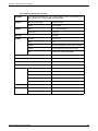
1
Theater Installation Guide 7!2 /& 7/ "!4 3 ,!. $/ &$ ,/. 3 ,$ /2 7 $ /& %! 2 $ 7! /& $ . ,! !2$ 49 '%3 %!$ 3 '). "% -!. 2,$ ,/ .' "! %34 4- 9 !. !2 " $ %' ). 3 7!2/&7/2,$0' ,!.$/&$%!$2 ,/.'%349!2$0' "!4-!.0' "%7)4#(%$0' &!.4!34)#0' 3)34%2(//$0' -!$!'!3#!20' © Copyright 2005-2006 Adaptive Micro Systems LLC. All rights reserved. Adaptive Micro Systems • 7840 North 86th Street • Milwaukee, WI 53224 USA • 414-357-2020 • 414-357-2029 (fax) • http://www.adaptivedisplays.com Trademarked names appear throughout this document. Rather than list the names and entities that own the trademarks or insert a trademark symbol with each mention of the trademarked name, the publisher states that it is using names for editorial purposes and to the benefit of the trademark owner with no intention of improperly using the trademark. The following are trademarks of Adaptive Micro Systems: Adaptive, Alpha, AlphaLert, AlphaNET, AlphaNet plus, AlphaEclipse, AlphaEclipse RoadStar, AlphaPremiere, AlphaTicker, AlphaVision, AlphaVision InfoTracker, Automode, BetaBrite, BetaBrite Director, BetaBrite Messaging Software, Big Dot, Director, EZ KEY II, EZ95, PagerNET, PPD, PrintPak, Serial Clock, Smart Alec, Solar, TimeNet. The distinctive trade dress of this product is a trademark claimed by Adaptive Micro Systems LLC. Due to continuing product innovation, specifications in this manual are subject to change without notice. August 24, 2006 97127016B Theater Installation Guide (pn 97127016B) Revision history Part number Date 9712-7016 November 14, 2005 9712-7016B August 24, 2006 Notes First release. Reorganized manual to flow in a similar sequence as an installation occurs and to add networking and addressing information. Related documentation Part number 97112101E Title AlphaVision FS Series Character Matrix Sign Installation Instructions Description This 20-page document describes how to install AlphaVision™ FS series LED signs and change the serial address. Information is also included for: • environmental requirements • electrical input • reducing electrical noise • temperature controls • connecting a sign to a computer • routine maintenance • mounting specifications 97000043C 97114201E ALPHA™ Series Sign Installation Instructions These instructions show how to change the serial address and how to mount ALPHA series signs. AlphaPremiere 9000 Series Sign Installation Instructions This 22-page manual describes the AlphaPremiere™ 9000 series LED sign. The 9000 series are 4-line, full-matrix, indoor LED signs that can be networked together. These signs can display both text and graphics, and speakers in the sign can generate tones. Alpha 220C Sign Trim Kit Installation Guide This document describes how to install an Alpha 220C sign into the optional trim kit enclosure. 97000043C ALPHA™ Series Sign Installation Instructions These instructions show how to change the serial address and how to mount ALPHA series signs. 97040002 ALPHA™ Remote Control Programming Manual This document describes how to use an infrared Remote Control to program the following signs: Alpha 200, 300, 400, 4000, and 7000 series signs. Also for Big Dot and Solar signs. 97101401A Theater Installation Guide (pn 97127016B) Contents Safety information . . . . . . . . . . . . . . . . . . . . . . . . . . . . . . . . . . . . . . . . . . . . . . . . . . . . . . . . . . . . . . . . . . . . . . . . . . . . . 5 Warnings and cautions. . . . . . . . . . . . . . . . . . . . . . . . . . . . . . . . . . . . . . . . . . . . . . . . . . . . . . . . . . . . . . . . . . . . . . 5 Controlling electrostatic discharge (ESD). . . . . . . . . . . . . . . . . . . . . . . . . . . . . . . . . . . . . . . . . . . . . . . . . . . . . . . . 5 Introduction . . . . . . . . . . . . . . . . . . . . . . . . . . . . . . . . . . . . . . . . . . . . . . . . . . . . . . . . . . . . . . . . . . . . . .6 How to use this guide . . . . . . . . . . . . . . . . . . . . . . . . . . . . . . . . . . . . . . . . . . . . . . . . . . . . . . . . . . . . . . . . . . . . . . . . . . . 7 Overview . . . . . . . . . . . . . . . . . . . . . . . . . . . . . . . . . . . . . . . . . . . . . . . . . . . . . . . . . . . . . . . . . . . . . . . . . . . . . . . . . . . . . 8 Purpose . . . . . . . . . . . . . . . . . . . . . . . . . . . . . . . . . . . . . . . . . . . . . . . . . . . . . . . . . . . . . . . . . . . . . . . . . . . . . . . . . 8 Electrical and Data Requirements . . . . . . . . . . . . . . . . . . . . . . . . . . . . . . . . . . . . . . . . . . . . . . . . . . . . . .9 Overview . . . . . . . . . . . . . . . . . . . . . . . . . . . . . . . . . . . . . . . . . . . . . . . . . . . . . . . . . . . . . . . . . . . . . . . . . . . . . . . . . . . . 10 Power and data requirements . . . . . . . . . . . . . . . . . . . . . . . . . . . . . . . . . . . . . . . . . . . . . . . . . . . . . . . . . . . . . . . . . . . . 11 Power and data hookups for Box Office and directional signs . . . . . . . . . . . . . . . . . . . . . . . . . . . . . . . . . . . . . . . 11 Power and data hookups for house signs . . . . . . . . . . . . . . . . . . . . . . . . . . . . . . . . . . . . . . . . . . . . . . . . . . . . . . 12 Sign networking and addressing considerations. . . . . . . . . . . . . . . . . . . . . . . . . . . . . . . . . . . . . . . . . . . . . . . . . . . . . . 13 About networking signs . . . . . . . . . . . . . . . . . . . . . . . . . . . . . . . . . . . . . . . . . . . . . . . . . . . . . . . . . . . . . . . . . . . . 13 RS485 Converter Box. . . . . . . . . . . . . . . . . . . . . . . . . . . . . . . . . . . . . . . . . . . . . . . . . . . . . . . . . . . . . . . . . . . . . . 14 About addressing signs . . . . . . . . . . . . . . . . . . . . . . . . . . . . . . . . . . . . . . . . . . . . . . . . . . . . . . . . . . . . . . . . . . . . 15 Addressing and Hanging Box Office and Directional Signs . . . . . . . . . . . . . . . . . . . . . . . . . . . . . . . . . .17 Overview . . . . . . . . . . . . . . . . . . . . . . . . . . . . . . . . . . . . . . . . . . . . . . . . . . . . . . . . . . . . . . . . . . . . . . . . . . . . . . . . . . . . 18 Setting Box Office and Directional Sign Addresses . . . . . . . . . . . . . . . . . . . . . . . . . . . . . . . . . . . . . . . . . . . . . . . . . . . . 19 Mounting Box Office and directional signs . . . . . . . . . . . . . . . . . . . . . . . . . . . . . . . . . . . . . . . . . . . . . . . . . . . . . . . . . . 22 Wall mounting specifications . . . . . . . . . . . . . . . . . . . . . . . . . . . . . . . . . . . . . . . . . . . . . . . . . . . . . . . . . . . . . . . . Preparation. . . . . . . . . . . . . . . . . . . . . . . . . . . . . . . . . . . . . . . . . . . . . . . . . . . . . . . . . . . . . . . . . . . . . . . . . . . . . . Mounting a sign on a wall . . . . . . . . . . . . . . . . . . . . . . . . . . . . . . . . . . . . . . . . . . . . . . . . . . . . . . . . . . . . . . . . . . Mounting a light box . . . . . . . . . . . . . . . . . . . . . . . . . . . . . . . . . . . . . . . . . . . . . . . . . . . . . . . . . . . . . . . . . . . . . . 22 25 26 27 Addressing and hanging house signs . . . . . . . . . . . . . . . . . . . . . . . . . . . . . . . . . . . . . . . . . . . . . . . . . .29 Overview . . . . . . . . . . . . . . . . . . . . . . . . . . . . . . . . . . . . . . . . . . . . . . . . . . . . . . . . . . . . . . . . . . . . . . . . . . . . . . . . . . . . 30 Setting house sign addresses . . . . . . . . . . . . . . . . . . . . . . . . . . . . . . . . . . . . . . . . . . . . . . . . . . . . . . . . . . . . . . . . . . . . 31 Mounting house signs . . . . . . . . . . . . . . . . . . . . . . . . . . . . . . . . . . . . . . . . . . . . . . . . . . . . . . . . . . . . . . . . . . . . . . . . . 33 Software and Installation Verification . . . . . . . . . . . . . . . . . . . . . . . . . . . . . . . . . . . . . . . . . . . . . . . . . .35 Overview . . . . . . . . . . . . . . . . . . . . . . . . . . . . . . . . . . . . . . . . . . . . . . . . . . . . . . . . . . . . . . . . . . . . . . . . . . . . . . . . . . . . 36 Wiring the sign network to the computer . . . . . . . . . . . . . . . . . . . . . . . . . . . . . . . . . . . . . . . . . . . . . . . . . . . . . . . . . . . 37 Software . . . . . . . . . . . . . . . . . . . . . . . . . . . . . . . . . . . . . . . . . . . . . . . . . . . . . . . . . . . . . . . . . . . . . . . . . . . . . . . . . . . . 38 Installing Simply Done Software . . . . . . . . . . . . . . . . . . . . . . . . . . . . . . . . . . . . . . . . . . . . . . . . . . . . . . . . . . . . . 38 Configuring STS . . . . . . . . . . . . . . . . . . . . . . . . . . . . . . . . . . . . . . . . . . . . . . . . . . . . . . . . . . . . . . . . . . . . . . . . . . 38 Verifying the installation . . . . . . . . . . . . . . . . . . . . . . . . . . . . . . . . . . . . . . . . . . . . . . . . . . . . . . . . . . . . . . . . . . . . . . . . 43 Verifying house sign addresses . . . . . . . . . . . . . . . . . . . . . . . . . . . . . . . . . . . . . . . . . . . . . . . . . . . . . . . . . . . . . . 43 Rebooting the displays. . . . . . . . . . . . . . . . . . . . . . . . . . . . . . . . . . . . . . . . . . . . . . . . . . . . . . . . . . . . . . . . . . . . . 43 iii Theater Installation Guide (pn 97127016B) Appendix . . . . . . . . . . . . . . . . . . . . . . . . . . . . . . . . . . . . . . . . . . . . . . . . . . . . . . . . . . . . . . . . . . . . . . . 45 Sign identification . . . . . . . . . . . . . . . . . . . . . . . . . . . . . . . . . . . . . . . . . . . . . . . . . . . . . . . . . . . . . . . . . . . . . . . . . . . . .46 Converter Box . . . . . . . . . . . . . . . . . . . . . . . . . . . . . . . . . . . . . . . . . . . . . . . . . . . . . . . . . . . . . . . . . . . . . . . . . . . . . . . .47 RS485 data cable information . . . . . . . . . . . . . . . . . . . . . . . . . . . . . . . . . . . . . . . . . . . . . . . . . . . . . . . . . . . . . . . . . . . .48 Adaptive Micro Systems Contact Information . . . . . . . . . . . . . . . . . . . . . . . . . . . . . . . . . . . . . . . . . . . . . . . . . . . . . . . .50 Customer Service . . . . . . . . . . . . . . . . . . . . . . . . . . . . . . . . . . . . . . . . . . . . . . . . . . . . . . . . . . . . . . . . . . . . . . . . .50 Technical Support . . . . . . . . . . . . . . . . . . . . . . . . . . . . . . . . . . . . . . . . . . . . . . . . . . . . . . . . . . . . . . . . . . . . . . . . .50 USA HEADQUARTERS. . . . . . . . . . . . . . . . . . . . . . . . . . . . . . . . . . . . . . . . . . . . . . . . . . . . . . . . . . . . . . . . . . . . . .50 EUROPE . . . . . . . . . . . . . . . . . . . . . . . . . . . . . . . . . . . . . . . . . . . . . . . . . . . . . . . . . . . . . . . . . . . . . . . . . . . . . . . .50 Theater Installation Guide (97127016B) iv Safety information Safety information Warnings and cautions Be aware of the following warnings when installing or servicing signs. WARNING Hazardous voltage. Contact with high voltage may cause death or serious injury. Always disconnect power to unit prior to servicing. SM1000A 7!2.).' !6%24)33%-%.4 #/52!.4$% &5)4%%,%6% 2ACCORDEMENT ALATERRE INDISPENSABLE AVANTLE RACCORDEMENT AURESEAU ()'(,%!+!'% #522%.4 %ARTHCONNECTION ESSENTIALBEFORE CONNECTING SUPPLY 3-! 7!2.).' 7!2.).' 0OSSIBLECRUSHHAZARD 5NPACKSIGNASDIRECTED /THERWISESIGNCOULDTIPOVER WHICHCOULDRESULTIN SERIOUSINJURYORDEATH 3- 0OSSIBLECRUSHHAZARD -OUNTUNITONAWALLTHATCAN SUPPORTATLEASTTIMESTHE UNITgSWEIGHT/THERWISEUNIT MAYFALLCAUSINGSERIOUS INJURYORDEATH 3-! Controlling electrostatic discharge (ESD) !44%.4)/. /"3%26%02%#!54)/.3 %,%#42/34!4)# 3%.3)4)6%$%6)#% This equipment contains components that may be damaged by “static electricity”, or electrostatic discharge. To prevent this from happening, be sure to follow the guidelines in Adaptive Tech Memo 00-0005, “Preventing Electrostatic Discharge (ESD) Damage,” available on our Web site at http://www.adaptivedisplays.com. Theater Installation Guide (97127016B) 5 Theater Installation Guide (pn 97127016B) Introduction 6 Introduction — How to use this guide How to use this guide This guide is intended to assist you with the configuration of ALPHA™ displays in your theater. Before you hang the first display and power it on, you need to ensure the data communication lines and electrical outlets are correctly wired and in the right locations. Once this has been accomplished, we recommend that you address the displays prior to mounting them. Finally, we address some basic setup steps for the Simply Theatre Signs software. You can obtain further software training and configuration assistance by enrolling in Adaptive Micro Systems STS E-training program. For questions regarding this guide or available products for the theater industry, please refer to “Adaptive Micro Systems Contact Information” on page 50. This guide consists of seven sections: Section Description Safety Important safety information regarding the installation of theater signage. Introduction Basic information regarding this guide. Electrical and data requirements • Power requirements for Box Office, directional, and house signs • Sign networking and addressing • About networking signs • RS485 Converter Box • About addressing signs Addressing and hanging Box Office and directional signs • Wall mounting specifications • Setting Box Office and directional sign addresses • Mounting Box Office and directional signs • Mounting light boxes Addressing and hanging house signs • Setting house sign address Setting up and configuring STS • Connecting the RS485 adapter • Ceiling and wall mounting house signs • Making the connections • Configuring STS • Verifying the installation Appendix • Sign identification • Converter Box • RS485 data cable information Theater Installation Guide (97127016B) 7 Introduction — Overview Overview This guide provides requirements and steps for installing Box Office, House, and Directional signs in a theater. Additionally, information regarding networking, addressing and installing Simply Theater Software is also provided. Figure 1: Sample signage arrangement in a theater. House signs 7!2 /& 7/ "!4 3 ,!. $/ &$ %!$ 3 ,$ /2 7 $ /& %! 2 &$ ! 7 / .$ ,! Box Office sign Directional signs 7!2/&7/2,$0' ,!.$/&$%!$2 ,/.'%349!2$0' "!4-!.0' "%7)4#(%$0' &!.4!34)#0' 3)34%2(//$0' -!$!'!3#!20' !2$ 49 '%3 ,/. 3 '). "% -!. 2,$ ,/ .' "! %34 4- 9 !. !2 " $ %' ). 3 Box Office sign Purpose This manual is intended for the theater signage installer. Please refer to "Related documentation" on the inside cover for more specific information about specific signs. Theater Installation Guide (97127016B) 8 Theater Installation Guide (pn 97127016B) Electrical and Data Requirements 9 Electrical and Data Requirements — Overview Overview 7!2 3 %'). /&7 !." /2,$ "!4- 3 ,!.$ /& 9!2$ %34 $%!$ ,/.' 3 ,$ /2 7 $ /& %! 2 $ 7! /& $ . ,! ,/ .' "! %34 4- 9 !. !2 " $ %' ). 3 7!2/&7/2,$0' ,!.$/&$%!$2 ,/.'%349!2$0' "!4-!.0' "%7)4#(%$0' &!.4!34)#0' 3)34%2(//$0' -!$!'!3#!20' Prior to hanging signs, power and data should be run to the sign locations. The following topics are covered in this section: • Power and data requirements, page 11 – Power and data hookups for Box Office and directional signs, page 11 – Power and data hookups for house signs, page 12 • Sign networking and addressing considerations, page 13 – About networking signs, page 13 – RS485 Converter Box, page 14 – About addressing signs, page 15 Theater Installation Guide (97127016B) 10 Electrical and Data Requirements — Power and data requirements Power and data requirements Power and data hookups for Box Office and directional signs Important! All cables should be kept as short as possible to ensure effective communication. Figure 2: Power and communication hookup for Box Office and directional signs Power outlet should be right behind this plug. Do NOT put power outlet directly under this plug. Power/Communications panel (back of sign) Theater Installation Guide (97127016B) Communication jacks — multiple signs can be daisy chained together (see “Sign networking and addressing considerations” 11 Electrical and Data Requirements — Power and data requirements Power and data hookups for house signs Important! All cables should be kept as short as possible to ensure effective communication. Figure 3: Power and communication hookup for house signs House sign (back) Line power cord connection Communication jacks — multiple signs can be “daisy chained” together (see “Sign networking and addressing considerations” on page 13): Theater Installation Guide (97127016B) 12 Electrical and Data Requirements — Sign networking and addressing considerations Sign networking and addressing considerations About networking signs Signs must be networked together in a bus topology. The bus topology uses a single cable from one end of the network to the other end. Signs, computers, or other devices can be added throughout the network at different locations. Figure 4: Acceptable sign network topology: Bus topology (single branch or “daisy chaining”) Converter Box (Terminate) Terminate !LPHASIGN !LPHASIGN !LPHASIGN Converter Box (Terminate) Terminate !LPHASIGN !LPHASIGN !LPHASIGN Converter Box (Do NOT Terminate) Terminate !LPHASIGN Theater Installation Guide (97127016B) !LPHASIGN !LPHASIGN Terminate !LPHASIGN 13 Electrical and Data Requirements — Sign networking and addressing considerations Other network topologies, such as the one in the following illustration, are not recommended. Figure 5: Unacceptable network topology: Star topology (multiple branches) !LPHASIGN !LPHASIGN !LPHASIGN !LPHASIGN !LPHASIGN !LPHASIGN !LPHASIGN !LPHASIGN RS485 Converter Box The signs communicate on an RS485 network which is the best choice for transferring messages over long distances. This means that messages sent from the computer must be converted to RS485. The RS485 converter box is used for this purpose. It must be located between the sign computer and the signs. See Figure 6: "Method 1 — Converter Box located at one end of sign network" and Figure 7: "Method 2 — Converter Box located in middle of sign network" for examples of where to position the converter box on the network. NOTE: See “Converter Box” on page 47 and “RS485 data cable information” on page 48 for more information RS485 converter boxes and cable specifications. Figure 6: Method 1 — Converter Box located at one end of sign network #ONVERTER"OX PN 23DATACABLE PN FOOTCOMPUTERCABLE SEE./4%BELOW #OMPUTERRUNNING 3IMPLY4HEATER 3OFTWARE 7!2/&4(%7/2,$3 23CABLE FOOTOR FOOT 7!2/&4(%7/2,$3 #OMMUNICATION7ALL0LATE#ONNECTIONS 7IRECRIMP ./4% 0LENUM23DATACABLE s!DAPTIVE"ELDIN .ONPLENUM23DATACABLE s!DAPTIVE"ELDIN! Theater Installation Guide (97127016B) 23WIRE "LACK 2ED 3HIELD 7ALLPLATE "LACK 9ELLOW #ONNECT3HIELDWIRESTO EACHOTHERNOTTOWALLPLATE 14 Electrical and Data Requirements — Sign networking and addressing considerations Figure 7: Method 2 — Converter Box located in middle of sign network 23DATACABLE SEE./4%BELOW #ONVERTER"OX PN 7!2/&4(%7/2,$3 7!2/&4(%7/2,$3 23CABLE FOOTOR FOOT #OMMUNICATION7ALL0LATE#ONNECTIONS 7IRECRIMP FOOTCOMPUTERCABLE PN ./4% 0LENUM23DATACABLE s!DAPTIVE"ELDIN .ONPLENUM23DATACABLE s!DAPTIVE"ELDIN! 23WIRE "LACK 2ED 3HIELD #OMPUTERRUNNING 3IMPLY4HEATER 3OFTWARE 7ALLPLATE "LACK 9ELLOW #ONNECT3HIELDWIRESTO EACHOTHERNOTTOWALLPLATE About addressing signs The software and network uses sign addresses to identify each sign and send messages. To send messages to the correct signs, they must be correctly addressed. To make this easier, there is an addressing convention for each type of sign. By using this convention, you can be confident that the right messages will display on the appropriate sign(s). In general, sign addressing follows the conventions listed in Table 1: "Sign addressing conventions" Table 1: Sign addressing conventions Sign Type Starting Address Box Office 1 Directional 10 House Match auditorium number Outdoor 31 Box Office sign addressing considerations If your theater will display performance information on Box Office signs and will repeat the information, you can duplicate addresses. Figure 8: Sign banks ACCEPTED DESCENT, THE JOHN TUCKER MATERIAL GIR PG13 R PG13 PG 1:25 7:10 1:30 1:10 4:30 7:30 9:45 9:35 6:55 4:40 7:20 9:35 MIAMI VICE MONSTER HOUS PIRATES CARI STEP UP R PG PG13 PG13 Bank 1 Theater Installation Guide (97127016B) 7:15 1:05 1:15 1:20 9:50 3:00 5:05 4:20 7:45 4:45 7:05 9:25 ACCEPTED DESCENT, THE JOHN TUCKER MATERIAL GIR PG13 R PG13 PG 1:25 7:10 1:30 1:10 4:30 7:30 9:45 9:35 6:55 4:40 7:20 9:35 MIAMI VICE MONSTER HOUS PIRATES CARI STEP UP Bank 2 R PG PG13 PG13 7:15 1:05 1:15 1:20 9:50 3:00 5:05 4:20 7:45 4:45 7:05 9:25 ACCEPTED DESCENT, THE JOHN TUCKER MATERIAL GIR PG13 R PG13 PG 1:25 7:10 1:30 1:10 4:30 7:30 9:45 9:35 6:55 4:40 7:20 9:35 MIAMI VICE MONSTER HOUS PIRATES CARI STEP UP R PG PG13 PG13 7:15 1:05 1:15 1:20 9:50 3:00 5:05 4:20 7:45 4:45 7:05 9:25 Bank 3 15 Electrical and Data Requirements — Sign networking and addressing considerations Example A theater with multiple Box Offices wants to repeat the performance list three times. It takes two signs to display the full performance listing. These two signs are referred to as a “bank.” This same exact information can be repeated on the other two sign banks. To do this, they set the address for the first sign in each bank to 1 and the address for the second sign in each bank to 2. When the sign addressing is set up this way, all Box Office signs with the same address will display the same information at the same time. Sign addressing and the hexadecimal numbering system The hexadecimal numbering system is used to represent the sign address on the network. In this numbering system, 15 different numerals can be used in each of its positions. Since we only have 1-digit numerals 0-9, the hexadecimal system uses the letters A through F to represent the extra numerals. When a sign powers up, it uses the hexadecimal numbering system to display its address. This will appear familiar for sign addresses 1-9. But for an address of 10, for example, it would display 0A. You can use the Windows Calculator to quickly convert addresses between the numbering systems. To convert addresses between numbering systems: 1. On a computer with Windows, open the Calculator. 2. Select View | Scientific. 3. To convert a hexadecimal value to a decimal value, do the following: • • • Select the Hex option. Enter the (hexadecimal) address appearing on the sign. Select the Dec option. The decimal value will appear on the Calculator. 4. To convert a decimal value to a hexadecimal value, do the following: • • • Select the Dec option. Enter the address you want to convert to hexadecimal. Select the Hex option. The hexadecimal value will appear on the Calculator. Theater Installation Guide (97127016B) 16 Theater Installation Guide (pn 97127016B) Addressing and Hanging Box Office and Directional Signs 17 Addressing and Hanging Box Office and Directional Signs — Overview Overview Directional sign Address = 10 7!2 Directional sign Address = 11 3 %'). /&7 !." /2,$ "!4- 3 ,!.$ /& ,/.' 3 ,$ /2 7 $ /& %! 2 $ 7! /& $ . ,! Box Office sign Address = 1 9!2$ %34 $%!$ ,/ .' "! %34 4- 9 !. !2 " $ %' ). 3 7!2/&7/2,$0' ,!.$/&$%!$2 ,/.'%349!2$0' "!4-!.0' "%7)4#(%$0' &!.4!34)#0' 3)34%2(//$0' -!$!'!3#!20' Box Office sign Address = 2 The following topics are covered in this section: • Setting Box Office and Directional Sign Addresses, page 19 – Step 1: Open the sign, page 19 – Step 2: Set the sign’s DIP switches, page 20 • Mounting Box Office and directional signs, page 22 – Wall mounting specifications, page 22 – Preparation, page 25 – Mounting a sign on a wall, page 26 – Mounting a light box, page 27 Theater Installation Guide (97127016B) 18 Addressing and Hanging Box Office and Directional Signs — Setting Box Office and Directional Sign Addresses Setting Box Office and Directional Sign Addresses Step 1: Open the sign 1. Remove power from the sign. WARNING Hazardous voltage. Contact with high voltage may cause death or serious injury. Always disconnect power to unit prior to servicing. SM1000A 2. Remove the sign’s cover by loosening the clips that hold the cover in place: 3. Unscrew the vertical rails that hold the LED boards. Then lift up frame holding the LED boards and use the sign’s prop rod to hold the frame open: Vertical rail Prop rod Theater Installation Guide (97127016B) 19 Addressing and Hanging Box Office and Directional Signs — Setting Box Office and Directional Sign Addresses Step 2: Set the sign’s DIP switches 1. Locate the sign’s DIP switches:. Theater Installation Guide (97127016B) 20 Addressing and Hanging Box Office and Directional Signs — Setting Box Office and Directional Sign Addresses 2. Set the sign’s DIP switches as shown below: ON Set these DIP switches . . . For this address . . . 1 2 3 4 5 6 7 8 1 ON OFF OFF OFF OFF OFF OFF OFF 2 OFF ON OFF OFF OFF OFF OFF OFF 3 ON ON OFF OFF OFF OFF OFF OFF 4 OFF OFF ON OFF OFF OFF OFF OFF 5 ON OFF ON OFF OFF OFF OFF OFF 6 OFF ON ON OFF OFF OFF OFF OFF 7 ON ON ON OFF OFF OFF OFF OFF 8 OFF OFF OFF ON OFF OFF OFF OFF 9 ON OFF OFF ON OFF OFF OFF OFF 10 OFF ON OFF ON OFF OFF OFF OFF 11 ON ON OFF ON OFF OFF OFF OFF 12 OFF OFF ON ON OFF OFF OFF OFF 13 ON OFF ON ON OFF OFF OFF OFF 14 OFF ON ON ON OFF OFF OFF OFF 15 ON ON ON ON OFF OFF OFF OFF 16 OFF OFF OFF OFF ON OFF OFF OFF 17 ON OFF OFF OFF ON OFF OFF OFF 18 OFF ON OFF OFF ON OFF OFF OFF 19 ON ON OFF OFF ON OFF OFF OFF 20 OFF OFF ON OFF ON OFF OFF OFF 21 ON OFF ON OFF ON OFF OFF OFF 22 OFF ON ON OFF ON OFF OFF OFF 23 ON ON ON OFF ON OFF OFF OFF 24 OFF OFF OFF ON ON OFF OFF OFF 25 ON OFF OFF ON ON OFF OFF OFF 26 OFF ON OFF ON ON OFF OFF OFF 27 ON ON OFF ON ON OFF OFF OFF 28 OFF OFF ON ON ON OFF OFF OFF 29 ON OFF ON ON ON OFF OFF OFF 30 OFF ON ON ON ON OFF OFF OFF Theater Installation Guide (97127016B) 21 Addressing and Hanging Box Office and Directional Signs — Mounting Box Office and directional signs Mounting Box Office and directional signs Wall mounting specifications B D A C BACK OF BOX OFFICE OR DIRECTIONAL SIGN Theater Installation Guide (97127016B) Mounting brackets — used to mount the sign. Bottom brackets are only used if sign is mounted on an angle (see Figure 11 on page 26). 22 Addressing and Hanging Box Office and Directional Signs — Mounting Box Office and directional signs Table 2: Wall mounting specifications Dimensions Model number (see “Sign identification” on page 46) A (Height) B (Width) C (Vertical center-to-center distance between shoulder bolts) D (Horizontal center-to-center distance between shoulder bolts) Weight (approx.) TCM032006P02zzz 17.65 in. 44.8 cm. 43.20 in. 109.7 cm. 15.03 in. 38.2 cm. 40.58 in. 103.1 cm. 60 lbs. 27 kg. TCM032008P02zzz 22.05 in. 56.0 cm. 43.20 in. 109.7 cm. 19.43 in. 49.4 cm. 40.58 in. 103.1 cm. 71 lbs. 32 kg. TCM032010P02zzz 26.46 in. 67.2 cm. 43.20 in. 109.7 cm. 23.84 in. 60.5 cm. 40.58 in. 103.1 cm. 82 lbs. 37 kg. TCM032012P02zzz 30.83 in. 78.3 cm. 43.20 in. 109.7 cm. 28.21 in. 71.5 cm. 40.58 in. 103.1 cm. 93 lbs. 42 kg. TCM040006P02zzz 17.65 in. 44.8 cm. 52.83 in. 134.2 cm. 15.03 in. 38.2 cm. 50.21 in. 127.5 cm. 71 lbs. 32 kg. 22.05 in. 56.0 cm. 52.83 in. 134.2 cm. 19.43 in. 49.4 cm. 50.21 in. 127.5 cm. 82 lbs. 37 kg. 26.46 in. 67.2 cm. 52.83 in. 134.2 cm. 23.84 in. 60.6 cm. 50.21 in. 127.5 cm. 93 lbs. 42 kg. TCM040012P02zzz 30.83 in. 78.3 cm. 52.83 in. 134.2 cm. 28.21 in. 71.6 cm. 50.21 in. 127.5 cm. 104 lbs. 47 kg. TCM048006P02zzz 17.65 in. 44.8 cm. 62.40 in. 158.5 cm. 15.03 in. 38.2 cm. 59.78 in. 151.8 cm. 82 lbs. 37 kg. TCM048008P02zzz 22.05 in. 56.0 cm. 62.40 in. 158.5 cm. 19.43 in. 49.4 cm. 59.78 in. 151.8 cm. 93 lbs. 42 kg. TCM048010P02zzz 26.46 in. 67.2 cm. 62.40 in. 158.5 cm. 23.84 in. 60.6 cm. 59.78 in. 151.8 cm. 104 lbs. 47 kg. TCM048012P02zzz 30.83 in. 78.3 cm. 62.40 in. 158.5 cm. 28.21 in. 71.6 cm. 59.78 in. 151.8 cm. 116 lbs. 53 kg. TCM040008P02zzz TCM040010P02zzz Character size 1.4 inch Theater Installation Guide (97127016B) 23 Addressing and Hanging Box Office and Directional Signs — Mounting Box Office and directional signs Table 2: Wall mounting specifications (Continued) Dimensions Model number (see “Sign identification” on page 46) A (Height) B (Width) C (Vertical center-to-center distance between shoulder bolts) D (Horizontal center-to-center distance between shoulder bolts) Weight (approx.) TCM024004P03zzz 17.92 in. 45.5 cm. 48.77 in. 123.9 cm. 15.30 in. 38.86 cm. 46.15 in. 117.2 cm. 55 lbs. 25 kg. TCM024006P03zzz 24.52 in. 62.3 cm. 48.77 in. 123.9 cm. 21.90 in. 55.6 cm. 46.15 in. 117.2 cm. 74 lbs. 33.5 kg. TCM024008P03zzz 31.15 in. 79.1 cm. 48.77 in. 123.9 cm. 28.53 in. 72.5 cm. 46.15 in. 117.2 cm. 93 lbs. 42 kg. TCM024010P03zzz 37.71 in. 95.8 cm. 48.77 in. 123.9 cm. 35.09 in. 89.1 cm. 46.15 in. 117.2 cm. 112 lbs. 50.1 kg. TCM024012P03zzz 44.33 in. 112.6 cm. 48.77 in. 123.9 cm. 41.71 in. 105.9 cm. 46.15 in. 117.2 cm. 131 lbs. 59.4 kg. TCM032004P03zzz 17.92 in. 45.5 cm. 63.15 in. 160.4 cm. 15.30 in. 38.86 cm. 60.53 in. 153.7 cm. 74 lbs. 33.5 kg. TCM032006P03zzz 24.52 in. 62.3 cm. 63.15 in. 160.4 cm. 21.90 in. 55.6 cm. 60.53 in. 153.7 cm. 93 lbs. 42 kg. TCM032008P03zzz 31.15 in. 79.1 cm. 63.15 in. 160.4 cm. 28.53 in. 72.5 cm. 60.53 in. 153.7 cm. 112 lbs. 50.1 kg. TCM032010P03zzz 37.71 in. 95.8 cm. 63.15 in. 160.4 cm. 35.09 in. 89.1 cm. 60.53 in. 153.7 cm. 131 lbs. 59.4 kg. 44.33 in. 112.6 cm. 63.15 in. 160.4 cm. 41.71 in. 105.9 cm. 60.53 in. 153.7 cm. 150 lbs. 68 kg. 17.92 in. 45.5 cm. 77.55 in. 197 cm. 15.30 in. 38.86 cm. 74.93 in. 190.3 cm. 93 lbs. 42 kg. TCM040006P03zzz 24.52 in. 62.3 cm. 77.55 in. 197 cm. 21.90 in. 55.6 cm. 74.93 in. 190.3 cm. 112 lbs. 50.1 kg. TCM040008P03zzz 31.15 in. 79.1 cm. 77.55 in. 197 cm. 28.53 in. 72.5 cm. 74.93 in. 190.3 cm. 131 lbs. 59.4 kg. TCM040010P03zzz 37.71 in. 95.8 cm. 77.55 in. 197 cm. 35.09 in. 89.1 cm. 74.93 in. 190.3 cm. 150 lbs. 68 kg. TCM040012P03zzz 44.33 in. 112.6 cm. 77.55 in. 197 cm. 41.71 in. 105.9 cm. 74.93 in. 190.3 cm. 169 lbs. 76.7 kg. TCM048004P03zzz 17.92 in. 45.5 cm. 91.96 in. 233.6 cm. 15.30 in. 38.86 cm. 89.34 in. 226.9 cm. 112 lbs. 50.1 kg. TCM048006P03zzz 24.52 in. 62.3 cm. 91.96 in. 233.6 cm. 21.90 in. 55.6 cm. 89.34 in. 226.9 cm. 131 lbs. 59.4 kg. TCM048008P03zzz 31.15 in. 79.1 cm. 91.96 in. 233.6 cm. 28.53 in. 72.5 cm. 89.34 in. 226.9 cm. 150 lbs. 68 kg. TCM048010P03zzz 37.71 in. 95.8 cm. 91.96 in. 233.6 cm. 35.09 in. 89.1 cm. 89.34 in. 226.9 cm. 169 lbs. 76.7 kg. TCM048012P03zzz 44.33 in. 112.6 cm. 91.96 in. 233.6 cm. 41.71 in. 105.9 cm. 89.34 in. 226.9 cm. 188 lbs. 85.3 kg. TCM032012P03zzz TCM040004P03zzz Character size 2.1 inch Theater Installation Guide (97127016B) 24 Addressing and Hanging Box Office and Directional Signs — Mounting Box Office and directional signs Preparation 7!2.).' WARNING 0OSSIBLECRUSHHAZARD -OUNTUNITONAWALLTHATCAN SUPPORTATLEASTTIMESTHE UNITgSWEIGHT/THERWISEUNIT MAYFALLCAUSINGSERIOUS INJURYORDEATH Hazardous voltage. Contact with high voltage may cause death or serious injury. Always disconnect power to unit prior to servicing. SM1000A 3-! Figure 9: Parts for mounting signs Mounting bracket Shoulder bolt Sign bumper and Adjustment bolt Retaining pin Attach mounting bolts to back of sign 1. Remove the screw from each of the four corners. 2. Attach a shoulder bolt (provided) into each of the top corners 3. Attach a sign bumper and adjustment bolt (provided) into each of the bottom corners. Theater Installation Guide (97127016B) 25 Addressing and Hanging Box Office and Directional Signs — Mounting Box Office and directional signs Mounting a sign on a wall Figure 10: Flush mounting Box Office or directional signs Mounting bracket (see below) BACK OF BOX OFFICE OR DIRECTIONAL SIGN Power/Communications panel Sign bumper For sign mounting dimensions, see “Wall mounting specifications” on page 22. Retaining pin Mounting bracket The fasteners that hold this bracket to a wall must be able to support 4 times the weight of the sign. Shoulder bolt Figure 11: Angle mounting Box Office or directional signs BACK OF BOX OFFICE OR DIRECTIONAL SIGN GN 3I CA ETI NB LTED AX AM OF IMUM Mounting brackets (see above) Four brackets must be used for angle mounting. For sign mounting dimensions, see “Wall mounting specifications” on page 22. Theater Installation Guide (97127016B) 26 Addressing and Hanging Box Office and Directional Signs — Mounting Box Office and directional signs Mounting a light box A light box is used to display a Mylar transparency image. The HEIGHT and WIDTH of this image depends on the size of the light box used. A light box is typically placed directly under a Box Office or Lobby Directional sign. Figure 12: Light box mounting considerations "ACKVIEW (%)'(4 7)$4( &RONTVIEW 4RANSPARENCYFILMIMAGEAREADASHEDLINE(%)'(4nvX7)$4(nv 4RANSPARENCYACCESS $//2 #,/3%$ -OUNTINGBRACKETS 0OWERCORD FT $//2 /0%. Theater Installation Guide (97127016B) 27 Addressing and Hanging Box Office and Directional Signs — Mounting Box Office and directional signs Figure 13: Mounting light boxes "ACKVIEW 3IDEVIEW v (%)'(4 (%)'(4nv v v v v $¿ v $ 7)$4( 3IDEVIEW -OUNTINGBRACKET v 7ALL v v v Xv !LPHA6ISION&3SIGN ./4% !LIGHTBOXCANBEATTACHEDDIRECTLYTO THEBOTTOMOFAN!LPHA6ISION&3SIGN #ONTACT!DAPTIVE-ICRO3YSTEMSFOR DETAILS Theater Installation Guide (97127016B) 28 Theater Installation Guide (pn 97127016B) Addressing and hanging house signs 29 Addressing and hanging house signs — Overview Overview House sign Address = 9 House sign Address = 4 7!2 3 %'). /&7 !." /2,$ "!4- 3 ,!.$ /& 9!2$ %34 $%!$ ,/.' 3 ,$ /2 7 $ /& %! 2 $ 7! /& $ . ,! ,/ .' "! %34 4- 9 !. !2 " $ %' ). 3 House sign Address = 7 House sign Address = 2 7!2/&7/2,$0' ,!.$/&$%!$2 ,/.'%349!2$0' "!4-!.0' "%7)4#(%$0' &!.4!34)#0' 3)34%2(//$0' -!$!'!3#!20' The following topics are covered in this section: • Setting house sign addresses, page 31 – Step 1: Open the sign:, page 31 – Step 2: Set the sign’s DIP switches, page 32 • Mounting house signs, page 33 Theater Installation Guide (97127016B) 30 Addressing and hanging house signs — Setting house sign addresses Setting house sign addresses These instructions apply to the ALPHA™ 220C series signs. Addresses for ALPHA™ 4000 and 7000 series signs are set via the hand held remote. Refer to “Related documentation” on page ii for applicable documentation. Step 1: Open the sign: 1. Remove power from the sign. WARNING Hazardous voltage. Contact with high voltage may cause death or serious injury. Always disconnect power to unit prior to servicing. SM1000A 2. Unscrew the cap from the end of the sign furthest from the power supply. Power supply Open this end. 3. Gently pull the sign’s circuit board out a few inches. Pull Theater Installation Guide (97127016B) 31 Addressing and hanging house signs — Setting house sign addresses Step 2: Set the sign’s DIP switches 1. Locate the sign’s DIP switches: 2. Set the sign’s DIP switches as shown below:. ON Set these DIP switches . . . For this address . . . 1 2 3 4 5 6 7 8 1 ON OFF OFF OFF OFF OFF OFF OFF 2 OFF ON OFF OFF OFF OFF OFF OFF 3 ON ON OFF OFF OFF OFF OFF OFF 4 OFF OFF ON OFF OFF OFF OFF OFF 5 ON OFF ON OFF OFF OFF OFF OFF 6 OFF ON ON OFF OFF OFF OFF OFF 7 ON ON ON OFF OFF OFF OFF OFF 8 OFF OFF OFF ON OFF OFF OFF OFF 9 ON OFF OFF ON OFF OFF OFF OFF 10 OFF ON OFF ON OFF OFF OFF OFF 11 ON ON OFF ON OFF OFF OFF OFF 12 OFF OFF ON ON OFF OFF OFF OFF 13 ON OFF ON ON OFF OFF OFF OFF 14 OFF ON ON ON OFF OFF OFF OFF 15 ON ON ON ON OFF OFF OFF OFF 16 OFF OFF OFF OFF ON OFF OFF OFF 17 ON OFF OFF OFF ON OFF OFF OFF 18 OFF ON OFF OFF ON OFF OFF OFF 19 ON ON OFF OFF ON OFF OFF OFF 20 OFF OFF ON OFF ON OFF OFF OFF 21 ON OFF ON OFF ON OFF OFF OFF 22 OFF ON ON OFF ON OFF OFF OFF 23 ON ON ON OFF ON OFF OFF OFF 24 OFF OFF OFF ON ON OFF OFF OFF 25 ON OFF OFF ON ON OFF OFF OFF 26 OFF ON OFF ON ON OFF OFF OFF 27 ON ON OFF ON ON OFF OFF OFF 28 OFF OFF ON ON ON OFF OFF OFF 29 ON OFF ON ON ON OFF OFF OFF 30 OFF ON ON ON ON OFF OFF OFF Theater Installation Guide (97127016B) 32 Addressing and hanging house signs — Mounting house signs Mounting house signs These instructions explain how to mount ALPHA 220C signs using the available trim kits. For information about mounting other types of signs, refer to the appropriate manual, see “Related documentation” on page ii. 7!2.).' WARNING 0OSSIBLECRUSHHAZARD -OUNTUNITONAWALLTHATCAN SUPPORTATLEASTTIMESTHE UNITgSWEIGHT/THERWISEUNIT MAYFALLCAUSINGSERIOUS INJURYORDEATH Hazardous voltage. Contact with high voltage may cause death or serious injury. Always disconnect power to unit prior to servicing. SM1000A 3-! Figure 14: Ceiling mounting Power outlet Communication wall plate — see “Sign networking and addressing considerations” on page 13. 7! 2 ,EA /& 4 (% 7 /2 ,$ VEA T FROMLEASTA THE IN SIG CHC NTO LEA AW RANC ALL E 3 Shown with the optional Alpha 220C Trim Kit - Ceiling Mount (pn 10149009). 4/06)%7 IN IN IN IN IN &2/.46)%7 3)$%6)%7 IN Theater Installation Guide (97127016B) 33 Addressing and hanging house signs — Mounting house signs Figure 15: Wall mounting Power outlet 7!2 ,EAVEA TLEA FROMT STAINCHC HESIG NTOTH LEARANCE ECEILIN G /&4 (%7 /2,$ 3 Communication wall plate — see “Sign networking and addressing considerations” on page 13. Shown with the optional Alpha 220C Trim Kit - Wall Mount (pn 68014013). 4/06)%7 IN IN IN IN &2/.46)%7 3)$%6)%7 IN Theater Installation Guide (97127016B) 34 Theater Installation Guide (pn 97127016B) Software and Installation Verification 35 Software and Installation Verification — Overview Overview In this section, you will be performing the final stage of the theater sign installation. This is where you will connect the computer to the signs and install and configure the software so you can begin sending messages. The Simply Theater Signs (STS) software is used to communicate to the signs. This software was designed to make it easier for you to complete the installation and configuration in as quick a time as possible. The steps required to complete the software installation include the following: • • • • Wiring the sign network to the computer, page 37 Software, page 38 Configuring STS, page 38 Verifying the installation, page 43 Theater Installation Guide (97127016B) 36 Software and Installation Verification — Wiring the sign network to the computer Wiring the sign network to the computer The following figure depicts an example of wiring the sign network to the computer running Simply Theater Signs. For more information, refer to “Networking Alpha Signs” (part number 97000112). Figure 16: Example of sign network wiring to the STS workstation A To next sign Alpha sign B C D E Alpha sign G F PC running STS software Item Part # Description A 1088-9107 End-of-line (EOL) terminator B — Ferrite (ferrite end toward sign) 1088-8624 8-foot RS485 cable 1086-8636 1-foot RS485 cable 4331-0602 Modular Network Adapter 1088-8002 1000-foot RS485 shielded plenum cable 7122-0283 100-foot RS485 shielded plenum cable 7122-0284 100-foot RS485 outdoor-rated shielded plenum cable F 1088-1111 Converter Box III with a Converter Box III AC Adapter: pn 4011-1201 (120 volt) pn 4011-4201 (230 volt) G 1088-8634 Type A9 RS232 cable (connects Converter Box III to PC RS232 port) C D E Theater Installation Guide (97127016B) 37 Software and Installation Verification — Software Software Installing Simply Done Software To install Simply Done Software, insert the CD-ROM into the drive and follow the prompts. If the CDROM does not automatically start, do the following: 1. Double-click the My Computer icon on the desktop. 2. Navigate to the CD-ROM drive (double-click the drive letter with the CD-ROM in it). 3. Double-click setup.exe and follow the prompts. Configuring STS This section only highlights some of the configuration settings. For more details on the complete configuration, refer to the online help. To set the COM ports: 1. Access the Dealer Maintenance Options screen in Simply Theatre Signs. Figure 17: Accessing the Dealer Maintenance Options screen. To access the Dealer Maintenance Options screen, click this icon. Theater Installation Guide (97127016B) 38 Software and Installation Verification — Software 2. Click the Communication Ports tab and then click the Edit button and make the appropriate changes. Figure 18: Editing the communication ports. Set the communication port settings as they apply to your location. To set the number of houses: 1. Access the Dealer Maintenance Options screen in Simply Theatre Signs. Figure 19: Accessing the Dealer Maintenance Options screen. To access the Dealer Maintenance Options screen, click this icon. Theater Installation Guide (97127016B) 39 Software and Installation Verification — Software 2. Click the Number of Houses tab and then click the Edit button. Update the number of houses and click the Commit Change button when done. Figure 20: Setting the number of houses. Set the number of houses and Theater Installation Guide (97127016B) 40 Software and Installation Verification — Software To configure the point of sale: 1. Access the General Settings screen. Figure 21: Accessing the Configuration screen. A. Click Configuration. Figure 22: Accessing the General Settings screen. B. Click General Settings. Theater Installation Guide (97127016B) 41 Software and Installation Verification — Software 2. Click the General Options tab, click Edit, and check the Use Point of Sale System box. Figure 23: Enabling the POS option. Check the Use Point of Sale System box. 3. Click the Point of Sale System tab and set the options as appropriate for the point of sale system used in your theater. Figure 24: Configuring the point of sale system information. Theater Installation Guide (97127016B) 42 Software and Installation Verification — Verifying the installation Verifying the installation Verifying house sign addresses When the house signs first boot up, they will display their hex address. Verify this is correct based on the house number. Refer to “About addressing signs” on page 15 for more information. Rebooting the displays These instructions apply to Box Office, directional, and outdoor signs because these signs must be reset in order to configure the memory and establish communications. This is done through the Simply Theatre Software. To reboot Box Office, directional, and outdoor signs: 1. Open the appropriate emulator and click the e. Figure 25: Opening the Box Office emulator. Select the appropriate emulator (the Box Office emulator is shown as an example). Theater Installation Guide (97127016B) 43 Software and Installation Verification — Verifying the installation 2. Click the ellipse button. Figure 26: Box Office sign emulator. Click this button to reset the sign. 3. Wait approximately two (2) minutes for the sign to reset. 4. Move to the next sign or emulator and reset the next sign. Figure 27: Moving to the next sign in the emulator. Use the slider to move to the next sign. You can navigate between signs using the slider in all of the emulators. Theater Installation Guide (97127016B) 44 Theater Installation Guide (pn 97127016B) Appendix 45 Appendix — Sign identification Sign identification B -/$%,./ 3%2)%3 6/,43 (Z !-03 4#-02%$ " 6!#^ (Z &4 & & / 2 ) . $ / / 2 5 3 % / . ,9 #%24)&)%$4/ #!.#3!34$ #.O #/.&/2-34/ 86 !.3)5,34$ .O #/-0,)%34/34$ !3.:3 4(%$)34).#4)6%42!$%$2%33/&4()302/$5#4)3! 42!$%-!2+/&!$!04)6%-)#2/3934%-3,,# A C D E $GDSWLYH0LFUR6\VWHPV//& 0LOZDXNHH:LVFRQVLQ86$ Identification label (back of sign) Item Name A Model number Model number description TCM048010P02RED LED color Pitch: P02=1.4” characters P03=2.1” characters Characters per line. Number of rows of characters Character matrix: CM None B Serial letter C Electrical information Input voltage, frequency, and amperage. D Date of manufacture Month, day, and year the sign was made. E Serial number Theater Installation Guide (97127016B) Revision level of sign. Consecutive, unique identification number. 46 Appendix — Converter Box Converter Box Front view A Back view F E D C B Table 3: Converter Box components Item A Name Description RS-232 TXD indicator Flashing = data being sent from the computer to the sign(s). RS-232 RXD indicator Flashing = data being sent from the sign(s) to the computer. Power indicator Lit = power is supplied to Converter Box. B RS-485 jack Optional RS485 connection. C Termination switch To turn Converter Box termination on, set switch to TERMINATED. To turn Converter Box termination off, set switch to UNTERMINATED. D RS485 connector Used to network signs together. E RS-232 connector Connect to a computer’s RS232 port. F DC power jack Used to power the Converter Box. Theater Installation Guide (97127016B) 47 Appendix — RS485 data cable information RS485 data cable information Two types of RS485 data cable are available from Adaptive: •RS485 plenum cable (7124-0203) — indoor/outdoor cable. If this cable is used outdoors, it should be encased in a UV-protectant casing. •RS485 non-plenum cable (7122-0203) — indoor cable. Table 4: RS485 plenum cable (7124-0203) Description 1/Pr. 24 AWG FFEP shielded cable, 100% aluminum Mylar and 95% tinned copper braid, 300V Type NEC/CMP LO-CAP (Belden 89841 equivalent) Conductor AWG size and stranding: 24 AWG 7/32 Material: Tinned copper Material: FFEP - Foam Fluorinated Ethylene Propylene Wall thickness: 0.020 inch Insulation Color code Assembly Black/Red Lay length: 2.0 inch L-H-L Binder: None Shield #1: Aluminum polyester foil shield. 100% coverage. Shield #2: Tinned copper braid shield. 95% coverage. Drain: 24 AWG 7/32 strand tinned copper Capacitance 12 pF/ft Nom. Velocity of Propagation 81.6% Impedance 120 ohms DC resistance 27.7 ohms per 1000 ft @ 68°F Jacket Material: FEP — Fluorinated Ethylene Propylene (Teflon®) Wall thickness: 0.015 inch Diameter: 0.176 inch Nom OD Color: Red Temperature: -70°C to 200°C Cable weight Markings 20.09 pounds/1000 ft Type: NEC CMP Legend: As desired. Theater Installation Guide (97127016B) 48 Appendix — RS485 data cable information Table 5: RS485 non-plenum cable (7122-0203) Description 1/Pr. 22 AWG FPE shielded cable, 100% aluminum Mylar and 95% tinned copper braid, 300V Type NEC/PLTC LO-CAP (Belden 3105A equivalent) Conductor AWG size and stranding: 22 AWG 7/0.0096 Material: Tinned copper Material: FPE - Foam Polyethylene Wall thickness: 0.020 inch Insulation Color code Assembly Black/Red Lay length: 2.5 inch L-H-L Binder: None Shield #1: Aluminum polyester foil shield. 100% coverage. Shield #2: Tinned copper braid shield. 95% coverage. Drain: 24 AWG 7/32 strand tinned copper Capacitance 11 pF/ft Nom. Velocity of Propagation 79.1% Impedance 120 ohms DC resistance 17.5 ohms per 1000 ft @ 68°F Jacket Material: PVC — Polyvinyl Chloride Wall thickness: 0.038 inch Diameter: 0.234 inch Nom OD Color: Black Temperature: 105°C Cable weight Markings 33.34 pounds/1000 ft Type: NEC PLTC Legend: As desired. Theater Installation Guide (97127016B) 49 Appendix — Adaptive Micro Systems Contact Information Adaptive Micro Systems Contact Information Customer Service Telephone:1-800-719-2838 or 1-414-357-2020, extension 274. Technical Support Technical support is offered twenty-four hours a day seven days a week. Telephone: 1-414-357-2020 extension 519. USA HEADQUARTERS 7840 North 86th Street Milwaukee, WI USA 53224 Tel: 414-357-2020 Fax: 414-357-2029 Email: [email protected] EUROPE 25 rue Irene Joliot-Curie 38320 Eybens France Tel: +33 4 76 14 76 00 Fax: +33 4 76 14 75 70 Theater Installation Guide (97127016B) 50