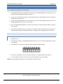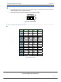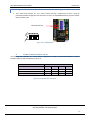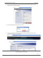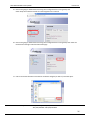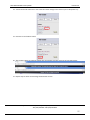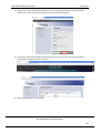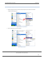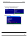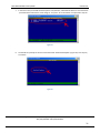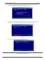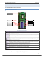
1
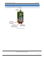
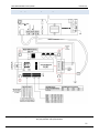
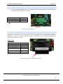
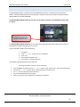
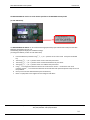
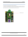
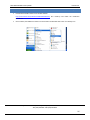
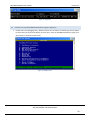
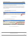
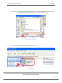
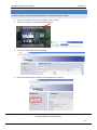
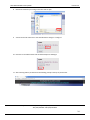
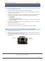
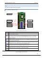
MCS-BMS-GATEWAY STARTUP GUIDE For Interfacing MCS-MAGNUM To Building Automation Systems Protocols BACnet MS/TP, Metasys N2 Open, LonWorks MCS‐BMS‐GATEWAY Startup Guide Revision 4.0 THIS PAGE INTENTIONALLY LEFT BLANK Micro Control Systems 5580 Enterprise Pkwy, Fort Myers, FL 33905 USA Web: www.mcscontrols.com Tel: (239) 694 0089 Fax: (239) 694 0031 2 MCS‐BMS‐GATEWAY Startup Guide Revision 4.0 TABLE OF CONTENTS 1 Introduction ............................................................................................................................................... 5 1.1 BTL Mark – BACnet Testing Laboratory ......................................................................................................... 5 1.2 LonMark Certification .................................................................................................................................... 5 2 Bacnet/LONWorks Setup through Protocessor MCS‐BMS‐GATEWAY ........................................................... 7 2.1 Installation steps for the customer................................................................................................................ 7 2.2 Configure the DIP Switches ........................................................................................................................... 7 2.2.1 Setting the Node/ID Device Instance (DIP Switch A0 – A7) for BACnet MS/TP, & Metasys N2 ............... 7 2.2.2 Setting the Serial Baud Rate (DIP Switch B0 – B3) for BACnet MS/TP & Metasys N2 .............................. 8 2.2.2.1 Baud Rate DIP Switch Selection ...................................................................................................... 8 2.2.3 Using S0 – S3 bank of DIP Switches to select and load Configuration Files ............................................. 9 A. LonWorks, BACnet MS/TP and N2 ................................................................................................ 9 3 Interfacing the MCS‐BMS‐GATEWAY .......................................................................................................... 10 3.1 MCS‐BMS‐GATEWAY showing connection ports ......................................................................................... 10 3.2 Wiring the MCS‐BMS‐GATEWAY to RS‐485 Field Protocol ............................. Error! Bookmark not defined. 3.2.1 Wiring diagram for connecting the MCS‐Magnum ................................................................................ 11 3.3 Wiring the MCS‐BMS‐GATEWAY Field Port to a LonWorks network ........................................................... 12 3.4 Power‐Up the MCS‐BMS‐GATEWAY ............................................................................................................ 12 3.5 MCS‐MAGNUM Address Settings ................................................................................................................ 13 3.6 Commissioning the MCS‐BMS‐GATEWAY on a LonWorks network ............................................................ 15 4 CREATING CSV FILES USING MCS‐CONFIG ................................................................................................... 20 5 Install and Run the Utility Software to Setup ip Address for BACnet/IP....................................................... 16 5.1 Connect the PC to the MCS‐BMS‐GATEWAY via the Ethernet port ............................................................ 17 5.2 Connect to the MCS‐BMS‐GATEWAY using RUI (RUInet) ........................................................................... 18 5.3 Set IP Address for BACnet/IP ....................................................................................................................... 19 Appendix A. Troubleshooting Tips ..................................................................................................................... 37 Appendix A.1. Connecting A PC to the MCS‐BMS‐GATEWAY .................................................................................. 37 Appendix A.2. No communication between the MCS‐Magnum and the MCS‐BMS‐GATEWAY .............................. 37 Appendix A.3. LED Diagnostics for Lonworks Communications between the MCS‐BMS‐GATEWAY and device . 38 A.2.1 LonWorks ProtoCessor LED’s ..................................................................................................................... 38 Appendix A.4. LED Diagnostics for Bacnet Communications between the MCS‐BMS‐GATEWAY and device ..... 40 A.3.1 Bacnet ProtoCessor LED’s .......................................................................................................................... 40 A.2.3 Main Board LEDs ....................................................................................................................................... 41 Appendix B. Reference ...................................................................................................................................... 42 Appendix B.1. Specifications .................................................................................................................................... 42 Appendix B.1.1. Compliance with UL Regulations ............................................................................................ 42 Appendix B.2. Address DIP Switch Settings ............................................................................................................. 43 Micro Control Systems 5580 Enterprise Pkwy, Fort Myers, FL 33905 USA Web: www.mcscontrols.com Tel: (239) 694 0089 Fax: (239) 694 0031 3 MCS‐BMS‐GATEWAY Startup Guide Revision 4.0 LIST OF FIGURES Figure 1: A0 – A7 DIP Switches ...................................................................................................................................... 7 Figure 2: B0 – B3 DIP Switches ...................................................................................................................................... 8 Figure 3 Baud Rate Table ............................................................................................................................................... 8 Figure 4: S0 – S3 DIP Switches ....................................................................................................................................... 9 Figure 5 Protocol Selection Switch Tables ..................................................................................................................... 9 Figure 6: MCS‐BMS‐GATEWAY .................................................................................................................................... 10 Figure 7 Gateway to RS‐485 wiring................................................................................. Error! Bookmark not defined. Figure 8 Lonworks network wiring .............................................................................................................................. 12 Figure 9 Wiring the power to the MCS‐BMS‐GATEWAY .............................................................................................. 12 Figure 10 Service Pin .................................................................................................................................................... 15 Figure 11 BMS points button ....................................................................................................................................... 20 Figure 12 The "CREATE MCS‐BMS‐GATEWAY" button ................................................................................................ 20 Figure 13 Save As prompt box ..................................................................................................................................... 21 Figure 14 CSV Files ....................................................................................................................................................... 21 Figure 15: Ethernet port location of MCS‐BMS‐GATEWAY .......................................................................................... 17 Figure 16: Ping Utility .................................................................................................................................................. 18 Figure 17: RUINET screen ............................................................................................................................................ 18 Figure 18 LonWorks ProtoCessor LED’s ....................................................................................................................... 38 Figure 19 Main Board LED's ......................................................................................................................................... 41 Micro Control Systems 5580 Enterprise Pkwy, Fort Myers, FL 33905 USA Web: www.mcscontrols.com Tel: (239) 694 0089 Fax: (239) 694 0031 4 MCS‐BMS‐GATEWAY Startup Guide 1 Revision 4.0 INTRODUCTION MCS‐BMS‐GATEWAY is an external, high performance Building Automation multi‐protocol gateway that has been preprogrammed to support BACnet®1MS/TP, Metasys®2 N2 by JCI, and LonWorks®3. Configurations for the various protocols are stored within the MCS‐BMS‐GATEWAY and are selectable via DIP switches for fast and easy installation. It is not necessary to download any configuration files to support the required applications. This document provides the necessary information to facilitate installation of the MCS‐BMS‐GATEWAY. 1.1 BTL Mark – BACnet Testing Laboratory The BTL Mark on the MCS‐BMS‐GATEWAY is a symbol that indicates to a consumer that a product has passed a series of rigorous tests conducted by an independent laboratory which verifies that the product correctly implements the BACnet features claimed in the listing. The mark is a symbol of a high‐quality BACnet product. Go to http://www.bacnetinternational.net/btl/ for more information about the BACnet Testing Laboratory. 1.2 LonMark Certification LonMark International is the recognized authority for certification, education, and promotion of interoperability standards for the benefit of manufacturers, integrators and end users. LonMark International has developed extensive product certification standards and tests to provide the integrator and user with confidence that products from multiple manufacturers utilizing LonMark devices work together. Micro Control Systems has more LonMark Certified gateways than any other gateway manufacturer, including the ProtoCessor, MCS‐BMS‐GATEWAY sand MCS‐BMS‐ GATEWAY for OEM applications and the full featured, configurable gateways. 1 BACnet is a registered trademark of ASHRAE Metasys is a registered trademark of Johnson Controls Inc. 3 LonMark is a registered trademark of LonMark International 4 LonWorks is a registered trademark of Echelon Corporation 2 Micro Control Systems 5580 Enterprise Pkwy, Fort Myers, FL 33905 USA Web: www.mcscontrols.com Tel: (239) 694 0089 Fax: (239) 694 0031 5 MCS‐BMS‐GATEWAY Startup Guide Revision 4.0 Micro Control Systems 5580 Enterprise Pkwy, Fort Myers, FL 33905 USA Web: www.mcscontrols.com Tel: (239) 694 0089 Fax: (239) 694 0031 6 MCS‐BMS‐GATEWAY Startup Guide 2 Revision 4.0 BACNET/LONWORKS SETUP THROUGH PROTOCESSOR MCS‐BMS‐GATEWAY 2.1 Installation steps for the customer 1. The MCS‐BMS‐GATEWAY is preprogrammed from factory for the MCS‐MAGNUM it will connect to. If you need to create the configuration please see section 4. 2. Set the A, B, and S DIP Switch banks for field protocol baud rate, Node‐ID/Device Instance, and proper configuration. (See section 2.2) 3. Connect the MCS‐BMS‐GATEWAY to the Field protocol port and the MCS‐Magnum Ethernet port to the MCS‐BMS‐GATEWAY Ethernet port. (See Section 0) 4. Power up the MCS‐BMS‐GATEWAY. After power up, the device is installed on BACnet MS/TP, or Metasys N2 or Lonworks 5. The IP address should already be set , however if an IP address change is required refer to Section 4 to run the RUInet utility program to change the IP address. No changes to the configuration file are necessary. 2.2 Configure the DIP Switches 2.2.1 Setting the Node Address /Device Instance (DIP Switch A0 – A7) for BACnet MS/TP, & Metasys N2 The A Bank DIP switches on the MCS‐BMS‐GATEWAY allow users to set the Node address/Device Instance on the RS‐485. DIP switches A0 – A7 can also be used to set the MAC Address for BACnet MS/TP. Figure 1: A0 – A7 DIP Switches Please refer to Appendix B.2 for the full range of addresses to set Node address/Device Instance. For Bacnet MS/TP the device instance is equal to the Node Address (0‐127) plus 18100 NOTE: When setting DIP Switches, please ensure that power to the board is OFF. Micro Control Systems 5580 Enterprise Pkwy, Fort Myers, FL 33905 USA Web: www.mcscontrols.com Tel: (239) 694 0089 Fax: (239) 694 0031 7 MCS‐BMS‐GATEWAY Startup Guide Revision 4.0 2.2.2 Setting the Serial Baud Rate (DIP Switch B0 – B3) for BACnet MS/TP & Metasys N2 DIP Switches B0 – B3 can be used to set the serial baud rate to match the baud rate provided by the Building Management System for BACnet MS/TP. Metasys N2 is always defaulted to 9600 baud and the B bank is disabled. Figure 2: B0 – B3 DIP Switches 2.2.2.1 Baud Rate DIP Switch Selection Baud Auto 110 300 600 1200 2400 4800 9600 19200 20833 28800 38400 57600 76800 115200 B0 B1 B2 B3 Off Off Off Off On Off Off Off Off On Off Off On On Off Off Off Off On Off On Off On Off Off On On Off On On On Off Off Off Off On On Off Off On Off On Off On On On Off On Off Off On On On Off On On Off On On On Figure 3 Baud Rate Table Micro Control Systems 5580 Enterprise Pkwy, Fort Myers, FL 33905 USA Web: www.mcscontrols.com Tel: (239) 694 0089 Fax: (239) 694 0031 8 MCS‐BMS‐GATEWAY Startup Guide Revision 4.0 2.2.3 Using S0 – S3 bank of DIP Switches to select and load Configuration Files The S bank of DIP switches, S0 ‐ S3 is used to select and load a configuration file from a group of pretested/preloaded configuration files which are stored in the MCS‐BMS‐GATEWAY (Lonworks, BACnet MS/TP or Metasys N2. S Bank DIP Switches Figure 4: S0 – S3 DIP Switches A. LonWorks, BACnet MS/TP and N2 The following chart describes S0 ‐ S3 DIP Switch configuration settings for MCS‐BMS‐GATEWAY to support LonWorks, BACnet® MS/TP and Metasys® N2 by JCI MCS‐BMS‐GATEWAY Profile – MCS‐BMS‐GATEWAY RER Lonworks Bacnet MS/TP N2 MCS‐BMS‐GATEWAY Bank DIP Switches S0 S1 S2 S3 Off Off Off Off On Off Off Off Off On Off Off Figure 5 Protocol Selection Switch Tables Micro Control Systems 5580 Enterprise Pkwy, Fort Myers, FL 33905 USA Web: www.mcscontrols.com Tel: (239) 694 0089 Fax: (239) 694 0031 9 MCS‐BMS‐GATEWAY Startup Guide 3 3.1 Revision 4.0 INTERFACING THE MCS‐BMS‐GATEWAY MCS‐BMS‐GATEWAY connection ports LonWorks Port LonWorks Service Pin 10/00 Ethernet Port. Connect to MCS‐MAGNUM RS‐485 Port for Connection to Bacnet MSTP or Metasys® N2 Power +/‐ and FRAME GND (FG) 9‐30 VDC 12‐24 VAC Figure 6: MCS‐BMS‐GATEWAY Micro Control Systems 5580 Enterprise Pkwy, Fort Myers, FL 33905 USA Web: www.mcscontrols.com Tel: (239) 694 0089 Fax: (239) 694 0031 10 MCS‐BMS‐GATEWAY Startup Guide 3.2 Revision 4.0 Wiring diagram for connecting the MCS‐Magnum Micro Control Systems 5580 Enterprise Pkwy, Fort Myers, FL 33905 USA Web: www.mcscontrols.com Tel: (239) 694 0089 Fax: (239) 694 0031 11 MCS‐BMS‐GATEWAY Startup Guide 3.3 Revision 4.0 Wiring the MCS‐BMS‐GATEWAY Field Port to a LonWorks network Connect the MCS‐BMS‐GATEWAY to the field network with the LonWorks terminal using a twisted pair non‐shielded cable. LonWorks has no polarity. MCS‐BMS‐GATEWAY Pin # Pin 1 Pin 2 Pin assignment Lon + Lon ‐ . Pin 1 Figure 7 Lonworks network wiring 3.4 Power‐Up the MCS‐BMS‐GATEWAY Apply power to the device. Ensure that the power supply used complies with the specifications provided in Appendix B.1. Ensure that the cable is grounded using the “Frame‐GND” terminal. The MCS‐BMS‐GATEWAY is factory set for 9‐30VDC or 12‐24 VAC. Voltage Pinouts MCS‐BMS‐GATEWAY Pin # Pin 1 Pin 2 Pin 3 Pin 4 Pin 5 Pin 6 Pin assignment RS‐485 + RS‐485 ‐ RS‐485 GND V + V ‐ FRAME GND (FG) Pin 1 Figure 8 Wiring the power to the MCS‐BMS‐GATEWAY Micro Control Systems 5580 Enterprise Pkwy, Fort Myers, FL 33905 USA Web: www.mcscontrols.com Tel: (239) 694 0089 Fax: (239) 694 0031 12 MCS‐BMS‐GATEWAY Startup Guide 3.5 Revision 4.0 MCS‐MAGNUM Address Settings The MCS‐BMS‐GATEWAY is connected to the MCS‐MAGNUM via Ethernet . The Bacnet Device ID and the IP address of the MCS‐MAGNUM must be setup properly to enable successful communications between the MCS‐ BMS‐GATEWAY and the MCS‐MAGNUM. The MCS‐MAGNUM BACNET DEVICE ID must be set to the address specified on the MCS‐BMS‐Gateways label (ex. 18111). The MCS‐MAGNUM BACNET DEVICE ID can be verified and changed (with the proper authorization code) from MCS‐Magnum’s keypad the keypad/LCD of a live unit. To get authorized on Magnum do the following: 1. 2. 3. 4. 5. Press ‘Menu’ Using , , , or position curser to ‘Passwords’ Press key. Enter 4 digit password & press . Press ‘Menu’ to make next selection. The following steps will display the Bacnet Device ID: (to change the address you first must be authorized) 1. 2. 3. 4. 5. Press the MENU key and then Using , , , or position curser to Serv Tools then press the ENTER key. then Using , , , or position curser to Bacnet Device ID then press Enter. Use , , curser to change the Bacnet Device ID. Set your desired address then press Enter. Reset or cycle power to the magnum for the change to take effect. Micro Control Systems 5580 Enterprise Pkwy, Fort Myers, FL 33905 USA Web: www.mcscontrols.com Tel: (239) 694 0089 Fax: (239) 694 0031 13 MCS‐BMS‐GATEWAY Startup Guide Revision 4.0 The MCS‐MAGNUM IP must be set to the address specified on the MCS‐BMS‐Gateways label (ex. 192.168.10.252). The MCS‐MAGNUM IP address can be verified and changed (with the proper authorization code) from the MCS‐ Magnum’s keypad/LCD of a live unit. The following steps will display the IP Address settings: (to change the address you first must be authorized) 1. Press the MENU key and then Using , , , or position curser to Serv Tools then press the ENTER key. 2. Then Using , , , or position curser to Serv Tools then press Enter. 3. Then Using , , , or position curser to Ethernet Network then press Enter. 4. Then Using , , , or position curser to IP address then press Enter. 5. Using , to increase and decrease the first set of values then use the to select the next set of numbers and use , to increase and decrease the second value and repeat the previous steps for rest of the ip address. 6. Once you have set the desired address press the Enter key. 7. Reset or cycle power to the magnum for the change to take effect. Micro Control Systems 5580 Enterprise Pkwy, Fort Myers, FL 33905 USA Web: www.mcscontrols.com Tel: (239) 694 0089 Fax: (239) 694 0031 14 MCS‐BMS‐GATEWAY Startup Guide Revision 4.0 3.6 Commissioning the MCS‐BMS‐GATEWAY on a LonWorks network Commissioning may only be performed by the LonWorks administrator. To commission the MCS‐BMS‐GATEWAY LonWorks port, press blue Service Pin to commission the device on a LonWorks network. This pin is located on the small LonWorks MCS‐BMS‐GATEWAY which sites on top of the base board. See the illustration on the MCS‐BMS‐GATEWAY where the button is located. LonWorks Service Pin Figure 9 Service Pin Micro Control Systems 5580 Enterprise Pkwy, Fort Myers, FL 33905 USA Web: www.mcscontrols.com Tel: (239) 694 0089 Fax: (239) 694 0031 15 MCS‐BMS‐GATEWAY Startup Guide 4 Revision 4.0 INSTALL AND RUN THE UTILITY SOFTWARE TO SETUP IP ADDRESS FOR BACNET/IP Download the RUINET Utilities from the MCS website http://mcscontrols.com/software.html#mcsBmsGateway Run Install.zip and follow the installation instructions Once installed, the FieldServer Utilities can be located in the Windows Start menu as a desktop icon Micro Control Systems 5580 Enterprise Pkwy, Fort Myers, FL 33905 USA Web: www.mcscontrols.com Tel: (239) 694 0089 Fax: (239) 694 0031 16 MCS‐BMS‐GATEWAY Startup Guide 4.1 Revision 4.0 Connect the PC to the MCS‐BMS‐GATEWAY via the Ethernet port Ethernet Port Figure 10: Ethernet port location of MCS‐BMS‐GATEWAY Disable any wireless Ethernet adapters on the PC/Laptop Disable firewall and virus protection software Connect a crossover cat5 Ethernet cable between the PC and MCS‐BMS‐GATEWAY The MCS Default IP Address of the MCS‐BMS‐GATEWAY is 192.168.10.85, Subnet Mask is 255.255.255.0 and the default gateway 192.168.10.1. If the PC and the MCS‐BMS‐GATEWAY are on different IP Networks, assign a static IP Address to the PC on the 192.168.10.xxx network. Go to Right‐click on Local Area Connection > Properties Highlight Select: Use the following IP address and enter an IP address, Subnet mask and default gateway on the same network (ex. See figure below) > > > Click Go to Start > Programs > Field Server Utilities > Ping Utility If the IP Address of the MCS‐BMS‐GATEWAY module appears on the screen, the MCS‐BMS‐GATEWAY is running (See Figure 16: Ping utility). If the module does not appear on the Ping Utility we may have an issue with the IP address. If this is the case try the following settings on your PC’s local area connection. IP Address 192.168.1.xxx(any available address other then 192.168.1.24), Subnet Mask is 255.255.255.0 and the default gateway 192.168.1.1. twice Micro Control Systems 5580 Enterprise Pkwy, Fort Myers, FL 33905 USA Web: www.mcscontrols.com Tel: (239) 694 0089 Fax: (239) 694 0031 17 MCS‐BMS‐GATEWAY Startup Guide Revision 4.0 Figure 11: Ping Utility 4.2 Connect to the MCS‐BMS‐GATEWAY using RUI (RUInet) Double click on the debugging utility, “RUINET” (Remote User Interface). The following screen will appear: (if RUInet does not automatically display the main menu, select the MCS‐BMS‐GATEWAY by typing the 2‐ digit number to the left of the title name). Figure 12: RUINET screen Micro Control Systems 5580 Enterprise Pkwy, Fort Myers, FL 33905 USA Web: www.mcscontrols.com Tel: (239) 694 0089 Fax: (239) 694 0031 18 MCS‐BMS‐GATEWAY Startup Guide 4.3 Revision 4.0 Set IP Address for BACnet/IP From the main menu, press “I” to enter the Edit IP Address Settings menu Press “1” to modify the IP address of the Ethernet adapter Type in a new IP address in the format 192.168.10.X and press <Enter> If necessary, press “2” to and change the netmask Type in a new Subnet Mask and press <Enter> If necessary, press “3” to and change the IP Gateway Type in a new IP Gateway and press <Enter> Note: If the MCS‐BMS‐GATEWAY is connected to a router, the IP Gateway of the MCS‐BMS‐GATEWAY should be set to the IP address of the router that it is connected to Unplug Ethernet cable from PC and connect the MCS‐BMS‐GATEWAY’s ethernet cable to the network switch or router Micro Control Systems 5580 Enterprise Pkwy, Fort Myers, FL 33905 USA Web: www.mcscontrols.com Tel: (239) 694 0089 Fax: (239) 694 0031 19 MCS‐BMS‐GATEWAY Startup Guide 5 Revision 4.0 CREATING CSV FILES USING MCS‐CONFIG The driver configuration file (CONFIG.CSV) for any driver combination ordered is loaded into the MCS‐BMS‐ GATEWAY and can be retrieved using the Remote User Interface Utility. The configuration file is in comma‐delimited format where entries within a line are separated by commas and the end of a line is indicated by an entry without a comma. This file can be edited using spreadsheet programs or any text editor. The following example will walk you through creating csv files for Bacnet MSTP, Lon, and Metasys N2 using the MCS‐Config software. Open your config file using the latest version of MCS‐Config. Select the BMS Points button. Figure 13 BMS points button Click on the CREATE MCS‐BMS‐GATEWAY CSV FILES Figure 14 The "CREATE MCS‐BMS‐GATEWAY" button Micro Control Systems 5580 Enterprise Pkwy, Fort Myers, FL 33905 USA Web: www.mcscontrols.com Tel: (239) 694 0089 Fax: (239) 694 0031 20 MCS‐BMS‐GATEWAY Startup Guide Revision 4.0 When you click the CREATE MCS‐BMS‐GATEWAY CSV FILES you will be prompted with a Save As prompt box. The file will be named automatically. Save it to your desired location. Figure 15 Save As prompt box MCS‐Config will create three csv files Bacnet, Lontalk, and N2. Figure 16 CSV Files Micro Control Systems 5580 Enterprise Pkwy, Fort Myers, FL 33905 USA Web: www.mcscontrols.com Tel: (239) 694 0089 Fax: (239) 694 0031 21 MCS‐BMS‐GATEWAY Startup Guide 6 Revision 4.0 PROGRAMMING THE MCS‐BMS‐GATEWAY WITH THE CSV FILES Method 1 (Programming the MCS‐BMS‐GATEWAY Via Compatible Web browser) 1. 2. Open your web browser. (IE9 or later, Google chrome, or Firefox) Type in the IP address of your MCS‐BMS‐GATEWAY card 3. You will be prompted with the following page 4. Select Setup then select file transfer from the navigation tree on the left Micro Control Systems 5580 Enterprise Pkwy, Fort Myers, FL 33905 USA Web: www.mcscontrols.com Tel: (239) 694 0089 Fax: (239) 694 0031 22 MCS‐BMS‐GATEWAY Startup Guide Revision 4.0 5. The configuration tab should be automatically selected. 6. Click on the choose file button to browse for the config.csv file. 7. You will be prompted with a dialog box to browse for your file. Micro Control Systems 5580 Enterprise Pkwy, Fort Myers, FL 33905 USA Web: www.mcscontrols.com Tel: (239) 694 0089 Fax: (239) 694 0031 23 MCS‐BMS‐GATEWAY Startup Guide Revision 4.0 8. Browse for and Select your config.csv file then click on open. 9. You will see the file name next to the chose file button change to “config.csv” 10. Now click on the submit button and the download process will begin. 11. After selecting submit you should see the following prompt at the top of your browser Micro Control Systems 5580 Enterprise Pkwy, Fort Myers, FL 33905 USA Web: www.mcscontrols.com Tel: (239) 694 0089 Fax: (239) 694 0031 24 MCS‐BMS‐GATEWAY Startup Guide Revision 4.0 12. Now we must restart the gateway in order for the file download to be complete. Select the “System Restart” button at the bottom of the page. 13. You will be prompted with the following box. Select “Ok”. 14. You will be prompted with the following message at the top of your browser, wait for the browser to automatically navigate back to the main menu. Micro Control Systems 5580 Enterprise Pkwy, Fort Myers, FL 33905 USA Web: www.mcscontrols.com Tel: (239) 694 0089 Fax: (239) 694 0031 25 MCS‐BMS‐GATEWAY Startup Guide Revision 4.0 15. Now we are going to download the remaining three configuration files to the gateway card. Select Setup then select file transfer from the navigation tree on the left 16. Now we are going to download the remaining three configuration files to the gateway card. Select the General tab on the right side of the file transfer page. 17. Click on the choose file button to browse for the bacnet config file (ex. Bac.csv) and select Open. Micro Control Systems 5580 Enterprise Pkwy, Fort Myers, FL 33905 USA Web: www.mcscontrols.com Tel: (239) 694 0089 Fax: (239) 694 0031 26 MCS‐BMS‐GATEWAY Startup Guide Revision 4.0 18. You will see the file name next to the “chose file” button change to the name of your csv file (ex.bac.csv) 19. Now click on the “Submit” button. 20. After clicking submit you will be prompted with the following messages at the top of your web browser. 21. Repeat steps 17‐20 for the remaining Lontalk and N2 csv files. Micro Control Systems 5580 Enterprise Pkwy, Fort Myers, FL 33905 USA Web: www.mcscontrols.com Tel: (239) 694 0089 Fax: (239) 694 0031 27 MCS‐BMS‐GATEWAY Startup Guide Revision 4.0 22. Once you have completed the download process for the remaining csv files you have to do one more system restart. Select the “System Restart” button at the bottom of the page. 23. You will be prompted with the following message at the top of your browser, wait for the browser to automatically navigate back to the main menu. 24. The download process in now complete. Micro Control Systems 5580 Enterprise Pkwy, Fort Myers, FL 33905 USA Web: www.mcscontrols.com Tel: (239) 694 0089 Fax: (239) 694 0031 28 MCS‐BMS‐GATEWAY Startup Guide Revision 4.0 Method 2 (Programming the MCS‐BMS‐GATEWAY Via Ruinet Remote User Interface Software) 1. Begin by copying the previously created csv files (See Figure 14) to the Remote User interface configuration folder (Figure 15). Figure 15 Location to copy CSV Files to 2. Now run the Remote User Interface software Figure 16 RUINET Software Micro Control Systems 5580 Enterprise Pkwy, Fort Myers, FL 33905 USA Web: www.mcscontrols.com Tel: (239) 694 0089 Fax: (239) 694 0031 29 MCS‐BMS‐GATEWAY Startup Guide Revision 4.0 3. 4. 5. You will then be prompted with one of the following screens (Figure 17) If you are prompted with the screen on the left press “Y’ for yes then press any key to continue to the following screen which should look like the right side of (Figure 17). IF you see the image on the right (Figure 17) continue to the next step. Figure 17 6. Now press “D” for Download Figure 18 Micro Control Systems 5580 Enterprise Pkwy, Fort Myers, FL 33905 USA Web: www.mcscontrols.com Tel: (239) 694 0089 Fax: (239) 694 0031 30 MCS‐BMS‐GATEWAY Startup Guide 7. Revision 4.0 In the next screen you should see three options. Local, Remote, and Download. Next to Local and remote you should have a file with the name config.csv. If so press “D” for download. If not proceed to step 10. Figure 19 8. You should see a prompt on the next screen that reads “Download Complete” (Figure 20). Press any key to continue. Figure 20 Micro Control Systems 5580 Enterprise Pkwy, Fort Myers, FL 33905 USA Web: www.mcscontrols.com Tel: (239) 694 0089 Fax: (239) 694 0031 31 MCS‐BMS‐GATEWAY Startup Guide 9. Revision 4.0 You should now be taken back to the “Download Configuration File” screen. Now press “O” and you should see the following prompt (Figure 21). Press any key to continue. Figure 21 10. Now press “L” and you should be prompted with the type Entry at the bottom of the page. Type in the name of the file you are trying to download (ex. Config.csv from step 7) then hit enter. Figure 22 11. The file name next to local should have changed to the new entry. Micro Control Systems 5580 Enterprise Pkwy, Fort Myers, FL 33905 USA Web: www.mcscontrols.com Tel: (239) 694 0089 Fax: (239) 694 0031 32 MCS‐BMS‐GATEWAY Startup Guide Revision 4.0 Figure 23 12. Now press “R” and you should be prompted with the type Entry at the bottom of the page. Retype the name of the file you are trying to download then hit enter. Figure 24 13. The filenames next to “Local” and “Remote” should be identical. Press “D” for download. Figure 25 Micro Control Systems 5580 Enterprise Pkwy, Fort Myers, FL 33905 USA Web: www.mcscontrols.com Tel: (239) 694 0089 Fax: (239) 694 0031 33 MCS‐BMS‐GATEWAY Startup Guide Revision 4.0 14. You should see a prompt on the next screen that reads “Download Complete” (Figure 26). Press any key to continue. Repeat this step for all four of your CSV files. Figure 26 15. Once you have downloaded all your files press escape to be taken back to the main menu. While in the main menu press and hold the SHIFT key. While Holding the SHIFT key press the number 1. Figure 27 Micro Control Systems 5580 Enterprise Pkwy, Fort Myers, FL 33905 USA Web: www.mcscontrols.com Tel: (239) 694 0089 Fax: (239) 694 0031 34 MCS‐BMS‐GATEWAY Startup Guide Revision 4.0 16. You should now see a prompt that says “Field Server Bust Restarting . . . .” Figure 28 17. You will prompted with the following screen (Figure 30) press “Y’ for yes then press any key to continue . You will be taken back to the Main menu. The download process is now complete. Figure 29 Micro Control Systems 5580 Enterprise Pkwy, Fort Myers, FL 33905 USA Web: www.mcscontrols.com Tel: (239) 694 0089 Fax: (239) 694 0031 35 MCS‐BMS‐GATEWAY Startup Guide Revision 4.0 18. The final step is to verify you have no errors. Once your back to the Main menu press “E” for errors. Figure 30 19. You should have a “No errors” prompt (See Figure 31). The download process is now complete. Figure 31 Micro Control Systems 5580 Enterprise Pkwy, Fort Myers, FL 33905 USA Web: www.mcscontrols.com Tel: (239) 694 0089 Fax: (239) 694 0031 36 MCS‐BMS‐GATEWAY Startup Guide Revision 4.0 Appendix A. Troubleshooting Tips Appendix A.1. Connecting A PC to the MCS‐BMS‐GATEWAY Confirm that the network cabling is correct Confirm that the computer network card is operational and correctly configured Confirm that there is an Ethernet adapter installed in the PC’s Device Manager List, and that it is configured to run the TCP/IP protocol Check that the IP netmask of the PC matches the MCS‐BMS‐GATEWAY. The Default IP Address of the MCS‐ BMS‐GATEWAY is 192.168.10.85, Subnet Mask is 255.255.255.0, Default Gateway is 192.168.10.1. Go to Start > Run Type in “ipconfig” The account settings should be displayed Ensure that the IP address is 192.168.10.xxx, the Subnet mask is 255.255.255.0 and the Default Gateway is 192.168.10.1 Ensure that the PC and MCS‐BMS‐GATEWAY are on the same IP Network, or assign a Static IP Address to the PC on the 192.168.10. network If Using Windows XP, ensure that the firewall is disabled Ensure that all other Ethernet cards active on the PC, especially wireless adapters are disabled Appendix A.2. No communication between the MCS‐Magnum and the MCS‐BMS‐GATEWAY Confirm that the network cabling is correct Check that the IP address, subnetmask, and the default gateway of the MCS‐Magnum match what the label on the MCS‐BMS‐GATEWAY says it should be set to. Check the LED’s on the Ethernet port. The yellow LED should be solid yellow the green LED should continuously flash. Green LED Ethernet Port Yellow LED Micro Control Systems 5580 Enterprise Pkwy, Fort Myers, FL 33905 USA Web: www.mcscontrols.com Tel: (239) 694 0089 Fax: (239) 694 0031 37 MCS‐BMS‐GATEWAY Startup Guide Revision 4.0 Appendix A.3. LED Diagnostics for Lonworks Communications between the MCS‐BMS‐GATEWAY and device Note: Please see the diagram below for LED Locations A.2.1 LonWorks ProtoCessor LED’s LON LED LON TX RUN SYS ERR COM ERR Config ERR Node offline – –– LON RX PWR PIC RUN PIC ERR UNUSED UNUSED Figure 17 LonWorks ProtoCessor LED’s Light PWR SYS ERR (LED1) COMM ERR (LED2) Config ERR (LED3) Node Offline (LED4) RUN (PIO) PIC RUN (LED5) Description This is the power light and should show steady green at all times when the MCS‐BMS‐GATEWAY MCS‐BMS‐GATEWAY is powered. The SYS ERR LED will flash once on power up and flash once 15 seconds after power up. A steady red light will indicate there is a system error on the MCS‐BMS‐GATEWAY. If this occurs, immediately report the related “system error” shown in the error screen of the RUI interface to Micro Control Systems for evaluation. The COMM ERR LED will flash once on power up and flash once 15 seconds after power up. A steady red light will indicate a communication error has occurred. To establish the cause of the error, go to the error screen of the RUI interface. The Config ERR LED will flash once on power up and flash once 15 seconds after power up. A steady amber light will indicate a configuration error exists in the active configuration. See the Error Screen in the Remote User Interface for a description of the configuration error. The Node Offline LED will flash once on power up and flash once 15 seconds after power up. If the Node Offline LED stays on solid, a Node Offline condition has occurred. The RUN LED will start flashing 20 seconds after power indicating normal operation. The MCS‐BMS‐ GATEWAY will be able to access RUINET once this LED starts flashing. The PIC RUN LED will flash indicating normal operation. Micro Control Systems 5580 Enterprise Pkwy, Fort Myers, FL 33905 USA Web: www.mcscontrols.com Tel: (239) 694 0089 Fax: (239) 694 0031 38 MCS‐BMS‐GATEWAY Startup Guide Light PIC ERR (LED6) LON‐TX LED LON‐RX LED LON‐SRV LED (next to Lon port) LED 7 LED 8 Revision 4.0 Description The PIC ERR LED will go on solid indicating there is a PIC error. On normal operation of MCS‐BMS‐GATEWAY, the TX LED will flash when a message is sent on the Lon port of the MCS‐BMS‐GATEWAY. On normal operation of MCS‐BMS‐GATEWAY, the RX LED will flash when a message is received on the Lon port of the MCS‐BMS‐GATEWAY. The LON‐SRV LED will flash if the MCS‐BMS‐GATEWAY is configured for implicit addressing and not commissioned. LED will be off if the MCS‐BMS‐GATEWAY is configured for implicit addressing and commissioned or if it is configured for explicit addressing. Not used Not used Micro Control Systems 5580 Enterprise Pkwy, Fort Myers, FL 33905 USA Web: www.mcscontrols.com Tel: (239) 694 0089 Fax: (239) 694 0031 39 MCS‐BMS‐GATEWAY Startup Guide Revision 4.0 Appendix A.4. LED Diagnostics for Bacnet Communications between the MCS‐BMS‐GATEWAY and device Note: Please see the diagram below for LED Locations A.3.1 Bacnet ProtoCessor LED’s LON LED RUN SYS ERR COM ERR Config ERR Node offline – –– PWR PIC RUN PIC ERR UNUSED UNUSED Figure 20 Bacnet ProtoCessor LED’s Light PWR SYS ERR (LED1) COMM ERR (LED2) Config ERR (LED3) Node Offline (LED4) RUN (PIO) PIC RUN (LED5) Description This is the power light and should show steady green at all times when the MCS‐BMS‐GATEWAY MCS‐BMS‐GATEWAY is powered. The SYS ERR LED will flash once on power up and flash once 15 seconds after power up. A steady red light will indicate there is a system error on the MCS‐BMS‐GATEWAY. If this occurs, immediately report the related “system error” shown in the error screen of the RUI interface to Micro Control Systems for evaluation. The COMM ERR LED will flash once on power up and flash once 15 seconds after power up. A steady red light will indicate a communication error has occurred. To establish the cause of the error, go to the error screen of the RUI interface. The Config ERR LED will flash once on power up and flash once 15 seconds after power up. A steady amber light will indicate a configuration error exists in the active configuration. See the Error Screen in the Remote User Interface for a description of the configuration error. The Node Offline LED will flash once on power up and flash once 15 seconds after power up. If the Node Offline LED stays on solid, a Node Offline condition has occurred. The RUN LED will start flashing 20 seconds after power indicating normal operation. The MCS‐BMS‐ GATEWAY will be able to access RUINET once this LED starts flashing. The PIC RUN LED will flash indicating normal operation. Micro Control Systems 5580 Enterprise Pkwy, Fort Myers, FL 33905 USA Web: www.mcscontrols.com Tel: (239) 694 0089 Fax: (239) 694 0031 40 MCS‐BMS‐GATEWAY Startup Guide Light PIC ERR (LED6) LON‐LED (next to Lon port) Revision 4.0 Description The PIC ERR LED will go on solid indicating there is a PIC error. The LON‐LED will flash every second. This LED is N/A when using bacnet protocol. A.2.3 Main Board LEDs RTC N/A ERR RX TX PWR Figure 18 Main Board LED's Light Description The SYS ERR LED will go on solid 15 seconds after power up. It will turn off after 5 seconds. A steady red light will indicate there is a system error on the MCS‐BMS‐GATEWAY. If this occurs, immediately report ERR the related “system error” shown in the error screen of the RUI interface to Micro Control Systems for evaluation. RX The RX LED will flash when a message is received on the socket port. TX The TX LED will flash when a message is sent on the socket port. This is the power light and should show steady green at all times when the MCS‐BMS‐GATEWAY is PWR powered. RTC Unused Micro Control Systems 5580 Enterprise Pkwy, Fort Myers, FL 33905 USA Web: www.mcscontrols.com Tel: (239) 694 0089 Fax: (239) 694 0031 41 MCS‐BMS‐GATEWAY Startup Guide Revision 4.0 Appendix B. Reference Appendix B.1. Specifications Electrical Connections Approvals MCS‐BMS‐GATEWAY One 6‐pin Phoenix connector, one RS‐485 One 6‐pin Phoenix connector, one RS‐485 +/‐ ground port, power +/‐ frame ground +/‐ ground port, power +/‐ frame ground port port One 3‐pin RS‐485 Phoenix connector, one One Ethernet 10/100 BaseT port RS‐485 +/‐ ground port One FTT‐10 LonWorks port One Ethernet‐10/100 Ethernet port CE (EN55022;EN55024; EN60950), UL916, FCC Class A Part 15, DNP3 Conformance Tested, OPC Self‐tested for Compliance, RoHS Compliant, CSA 205 Approved BTL Marked LonMark Certified Power Multi‐mode power adapter: 9 ‐ 30VDC or 12 ‐ 24VAC Requirements Physical 11.5 cm L x 8.2 cm W x 4.0 cm H (4.5 x 3.2 x 1.6 in.) Dimensions 0.2 kg (0.4 lbs) Weight Operating ‐40°C to 75°C (‐40°F to167°F) Temperature Surge EN61000‐4‐2 ESD EN61000‐4‐3 EMC EN61000‐4‐4 EFT Suppression 5 ‐ 90% RH (non‐condensing) Humidity (Specifications subject to change without notice) Appendix B.1.1. Compliance with UL Regulations For UL compliance, the following instructions must be met when operating the MCS‐BMS‐GATEWAY. The units shall be powered by listed LPS or Class 2 power supply suited to the expected operating temperature range. The interconnecting power connector and power cable shall: Comply with local electrical code Be suited to the expected operating temperature range Meet the current and voltage rating for the MCS‐BMS‐GATEWAY /Net Furthermore, the interconnecting power cable shall: Be of length not exceeding 3.05m (118.3”) Be constructed of materials rated VW‐1 or FT‐1 or better Micro Control Systems 5580 Enterprise Pkwy, Fort Myers, FL 33905 USA Web: www.mcscontrols.com Tel: (239) 694 0089 Fax: (239) 694 0031 42 MCS‐BMS‐GATEWAY Startup Guide Revision 4.0 If the unit is to be installed in an operating environment with a temperature above 65 °C, it should be installed in a Restricted Access Area requiring a key or a special tool to gain access. This device must not be connected to a LAN segment with outdoor wiring. Appendix B.2. Address DIP Switch Settings A7 A6 A5 A4 A3 A2 A1 A0 Address Off Off Off Off Off Off Off Off Off Off Off Off Off Off Off Off Off Off Off Off Off Off Off Off Off Off Off Off Off Off Off Off Off Off Off Off Off Off Off Off Off Off Off Off Off Off Off Off Off Off Off Off Off Off Off Off Off Off Off Off Off Off Off Off Off Off Off Off Off Off Off Off Off Off Off Off Off Off Off Off Off Off Off Off Off Off Off Off Off Off Off Off Off Off Off Off Off Off Off Off Off Off Off Off On On On On Off Off Off Off Off Off Off Off Off Off Off Off Off Off Off Off On On On On On On On On On On On On On On On On Off Off Off Off Off Off Off Off Off Off Off Off On On On On On On On On Off Off Off Off Off Off Off Off On On On On On On On On Off Off Off Off Off Off Off Off On On On On Off Off Off Off On On On On Off Off Off Off On On On On Off Off Off Off On On On On Off Off Off Off Off Off On On Off Off On On Off Off On On Off Off On On Off Off On On Off Off On On Off Off On On Off Off On On Off Off On On Off On Off On Off On Off On Off On Off On Off On Off On Off On Off On Off On Off On Off On Off On Off On Off On Off On Off On 0 1 2 3 4 5 6 7 8 9 10 11 12 13 14 15 16 17 18 19 20 21 22 23 24 25 26 27 28 29 30 31 32 33 34 35 Micro Control Systems 5580 Enterprise Pkwy, Fort Myers, FL 33905 USA Web: www.mcscontrols.com Tel: (239) 694 0089 Fax: (239) 694 0031 43 MCS‐BMS‐GATEWAY Startup Guide Revision 4.0 A7 A6 A5 A4 A3 A2 A1 A0 Address Off Off Off Off Off Off Off Off Off Off Off Off Off Off Off Off Off Off Off Off Off Off Off Off Off Off Off Off Off Off Off Off Off Off Off Off Off Off Off Off Off Off Off Off Off Off Off Off Off Off Off Off Off Off Off Off Off Off Off Off Off Off Off Off Off Off Off Off Off Off On On On On On On On On On On On On On On On On On On On On On On On On On On On On On On On On On On On On On On On On On On Off Off Off Off Off Off Off Off Off Off Off Off Off Off Off Off Off Off Off Off Off Off Off Off Off Off On On On On On On On On On On On On On On On On Off Off Off Off Off Off Off Off Off Off Off Off Off Off Off Off Off Off On On On On On On On On Off Off Off Off Off Off Off Off On On On On On On On On Off Off Off Off Off Off Off Off On On On On On On On On On On Off Off Off Off On On On On Off Off Off Off On On On On Off Off Off Off On On On On Off Off Off Off On On On On Off Off Off Off On On Off Off On On Off Off On On Off Off On On Off Off On On Off Off On On Off Off On On Off Off On On Off Off On On Off Off On On Off Off On On Off Off Off On Off On Off On Off On Off On Off On Off On Off On Off On Off On Off On Off On Off On Off On Off On Off On Off On Off On Off On Off On Off On 36 37 38 39 40 41 42 43 44 45 46 47 48 49 50 51 52 53 54 55 56 57 58 59 60 61 62 63 64 65 66 67 68 69 70 71 72 73 74 75 76 77 Micro Control Systems 5580 Enterprise Pkwy, Fort Myers, FL 33905 USA Web: www.mcscontrols.com Tel: (239) 694 0089 Fax: (239) 694 0031 44 MCS‐BMS‐GATEWAY Startup Guide Revision 4.0 A7 A6 A5 A4 A3 A2 A1 A0 Address Off Off Off Off Off Off Off Off Off Off Off Off Off Off Off Off Off Off Off Off Off Off Off Off Off Off Off Off Off Off Off Off Off Off Off Off Off Off Off Off Off Off On On On On On On On On On On On On On On On On On On On On On On On On On On On On On On On On On On On On On On On On On On Off Off Off Off Off Off Off Off Off Off Off Off Off Off Off Off Off Off On On On On On On On On On On On On On On On On On On On On On On On On Off Off On On On On On On On On On On On On On On On On Off Off Off Off Off Off Off Off Off Off Off Off Off Off Off Off On On On On On On On On On On Off Off Off Off Off Off Off Off On On On On On On On On Off Off Off Off Off Off Off Off On On On On On On On On Off Off Off Off Off Off Off Off On On Off Off Off Off On On On On Off Off Off Off On On On On Off Off Off Off On On On On Off Off Off Off On On On On Off Off Off Off On On On On On On Off Off On On Off Off On On Off Off On On Off Off On On Off Off On On Off Off On On Off Off On On Off Off On On Off Off On On Off Off On On Off On Off On Off On Off On Off On Off On Off On Off On Off On Off On Off On Off On Off On Off On Off On Off On Off On Off On Off On Off On Off On 78 79 80 81 82 83 84 85 86 87 88 89 90 91 92 93 94 95 96 97 98 99 100 101 102 103 104 105 106 107 108 109 110 111 112 113 114 115 116 117 118 119 Micro Control Systems 5580 Enterprise Pkwy, Fort Myers, FL 33905 USA Web: www.mcscontrols.com Tel: (239) 694 0089 Fax: (239) 694 0031 45 MCS‐BMS‐GATEWAY Startup Guide Revision 4.0 A7 A6 A5 A4 A3 A2 A1 A0 Address Off Off Off Off Off Off Off Off On On On On On On On On On On On On On On On On On On On On On On On On On On On On On On On On On On On On On On On On On On Off Off Off Off Off Off Off Off Off Off Off Off Off Off Off Off Off Off Off Off Off Off Off Off Off Off Off Off Off Off Off Off Off Off On On On On On On On On Off Off Off Off Off Off Off Off Off Off Off Off Off Off Off Off Off Off Off Off Off Off Off Off Off Off Off Off Off Off Off Off On On On On On On On On On On Off Off Off Off Off Off Off Off Off Off Off Off Off Off Off Off On On On On On On On On On On On On On On On On Off Off On On On On On On On On Off Off Off Off Off Off Off Off On On On On On On On On Off Off Off Off Off Off Off Off On On On On On On On On Off Off Off Off Off Off On On On On Off Off Off Off On On On On Off Off Off Off On On On On Off Off Off Off On On On On Off Off Off Off On On On On Off Off Off Off On On Off Off On On Off Off On On Off Off On On Off Off On On Off Off On On Off Off On On Off Off On On Off Off On On Off Off On On Off Off Off On Off On Off On Off On Off On Off On Off On Off On Off On Off On Off On Off On Off On Off On Off On Off On Off On Off On Off On Off On Off On 120 121 122 123 124 125 126 127 128 129 130 131 132 133 134 135 136 137 138 139 140 141 142 143 144 145 146 147 148 149 150 151 152 153 154 155 156 157 158 159 160 161 Micro Control Systems 5580 Enterprise Pkwy, Fort Myers, FL 33905 USA Web: www.mcscontrols.com Tel: (239) 694 0089 Fax: (239) 694 0031 46 MCS‐BMS‐GATEWAY Startup Guide Revision 4.0 A7 A6 A5 A4 A3 A2 A1 A0 Address On On On On On On On On On On On On On On On On On On On On On On On On On On On On On On On On On On On On On On On On On On Off Off Off Off Off Off Off Off Off Off Off Off Off Off Off Off Off Off Off Off Off Off Off Off Off Off Off Off Off Off On On On On On On On On On On On On On On On On On On On On On On On On On On On On On On On On On On On On On On On On On On Off Off Off Off Off Off Off Off Off Off Off Off Off Off Off Off Off Off Off Off Off Off Off Off Off Off On On On On On On On On On On On On On On On On Off Off Off Off Off Off Off Off Off Off Off Off Off Off Off Off Off Off On On On On On On On On Off Off Off Off Off Off Off Off On On On On On On On On Off Off Off Off Off Off Off Off On On On On Off Off On On On On Off Off Off Off On On On On Off Off Off Off On On On On Off Off Off Off On On On On Off Off Off Off On On On On Off Off Off Off On On Off Off On On Off Off On On Off Off On On Off Off On On Off Off On On Off Off On On Off Off On On Off Off On On Off Off On On Off Off On On Off On Off On Off On Off On Off On Off On Off On Off On Off On Off On Off On Off On Off On Off On Off On Off On Off On Off On Off On Off On Off On 162 163 164 165 166 167 168 169 170 171 172 173 174 175 176 177 178 179 180 181 182 183 184 185 186 187 188 189 190 191 192 193 194 195 196 197 198 199 200 201 202 203 Micro Control Systems 5580 Enterprise Pkwy, Fort Myers, FL 33905 USA Web: www.mcscontrols.com Tel: (239) 694 0089 Fax: (239) 694 0031 47 MCS‐BMS‐GATEWAY Startup Guide Revision 4.0 A7 A6 A5 A4 A3 A2 A1 A0 Address On On On On On On On On On On On On On On On On On On On On On On On On On On On On On On On On On On On On On On On On On On On On On On On On On On On On On On On On On On On On On On On On On On On On On On On On On On On On On On On On On On On On Off Off Off Off Off Off Off Off Off Off Off Off Off Off Off Off Off Off Off Off On On On On On On On On On On On On On On On On On On On On On On Off Off Off Off On On On On On On On On On On On On On On On On Off Off Off Off Off Off Off Off Off Off Off Off Off Off Off Off On On On On On On On On On On Off Off Off Off Off Off Off Off On On On On On On On On Off Off Off Off Off Off Off Off On On On On On On On On Off Off Off Off Off Off On On On On Off Off Off Off On On On On Off Off Off Off On On On On Off Off Off Off On On On On Off Off Off Off On On On On Off Off Off Off On On Off Off On On Off Off On On Off Off On On Off Off On On Off Off On On Off Off On On Off Off On On Off Off On On Off Off On On Off Off On On Off Off Off On Off On Off On Off On Off On Off On Off On Off On Off On Off On Off On Off On Off On Off On Off On Off On Off On Off On Off On Off On Off On 204 205 206 207 208 209 210 211 212 213 214 215 216 217 218 219 220 221 222 223 224 225 226 227 228 229 230 231 232 233 234 235 236 237 238 239 240 241 242 243 244 245 Micro Control Systems 5580 Enterprise Pkwy, Fort Myers, FL 33905 USA Web: www.mcscontrols.com Tel: (239) 694 0089 Fax: (239) 694 0031 48 MCS‐BMS‐GATEWAY Startup Guide Revision 4.0 A7 A6 A5 A4 A3 A2 A1 A0 Address On On On On On On On On On On On On On On On On On On On On On On On On On On On On On On On On On On On On On On On On Off Off On On On On On On On On On On Off Off Off Off On On On On On On Off Off On On Off Off On On Off On Off On Off On Off On Off On 246 247 248 249 250 251 252 253 254 255 Micro Control Systems 5580 Enterprise Pkwy, Fort Myers, FL 33905 USA Web: www.mcscontrols.com Tel: (239) 694 0089 Fax: (239) 694 0031 49